
Finite element modelling versus classic beam theory: morphologically
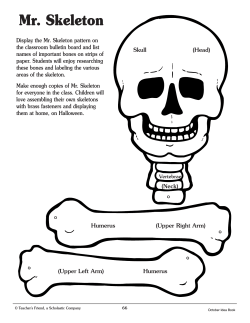
Downloaded from on October 6, 2014
Finite element modelling versus classic beam theory:
comparing methods for stress estimation in a morphologically
diverse sample of vertebrate long bones
Charlotte A. Brassey, Lee Margetts, Andrew C. Kitchener, Philip J. Withers, Phillip L. Manning and
William I. Sellers
J. R. Soc. Interface 2013 10, 20120823, published 21 November 2012
Supplementary data
"Data Supplement"
/content/suppl/2012/11/20/rsif.2012.0823.DC1.html
References
This article cites 39 articles, 8 of which can be accessed free
Subject collections
Articles on similar topics can be found in the following collections
/content/10/79/20120823.full.html#ref-list-1
computational biology (319 articles)
Email alerting service
Receive free email alerts when new articles cite this article - sign up in the box at the top
right-hand corner of the article or click here
To subscribe to J. R. Soc. Interface go to: /subscriptions
Downloaded from on October 6, 2014
rsif.royalsocietypublishing.org
Finite element modelling versus classic
beam theory: comparing methods for
stress estimation in a morphologically
diverse sample of vertebrate long bones
Charlotte A. Brassey1, Lee Margetts2,3, Andrew C. Kitchener5,6,
Philip J. Withers4, Phillip L. Manning2 and William I. Sellers1
Research
1
Faculty of Life Sciences, 2School of Earth, Atmospheric and Environmental Sciences, 3Research Computing, and
School of Materials, University of Manchester, Manchester M13 9PL, UK
5
Department of Natural Sciences, National Museums Scotland, Edinburgh EH1 1JF, UK
6
Institute of Geography, School of Geosciences, University of Edinburgh, Drummond Street, Edinburgh EH8 9XP, UK
4
Cite this article: Brassey CA, Margetts L,
Kitchener AC, Withers PJ, Manning PL, Sellers
WI. 2013 Finite element modelling versus
classic beam theory: comparing methods for
stress estimation in a morphologically diverse
sample of vertebrate long bones. J R Soc
Interface 10: 20120823.
http://dx.doi.org/10.1098/rsif.2012.0823
Received: 8 October 2012
Accepted: 31 October 2012
Subject Areas:
biomechanics, computational biology
Keywords:
finite element analysis, beam theory,
biomechanics, curvature, cross-sectional
asymmetry
Author for correspondence:
Charlotte A. Brassey
e-mail: [email protected]
ster.ac.uk
Classic beam theory is frequently used in biomechanics to model the stress
behaviour of vertebrate long bones, particularly when creating intraspecific
scaling models. Although methodologically straightforward, classic beam
theory requires complex irregular bones to be approximated as slender
beams, and the errors associated with simplifying complex organic structures to such an extent are unknown. Alternative approaches, such as
finite element analysis (FEA), while much more time-consuming to perform,
require no such assumptions. This study compares the results obtained
using classic beam theory with those from FEA to quantify the beam
theory errors and to provide recommendations about when a full FEA is
essential for reasonable biomechanical predictions. High-resolution computed tomographic scans of eight vertebrate long bones were used to
calculate diaphyseal stress owing to various loading regimes. Under compression, FEA values of minimum principal stress (smin) were on average
142 per cent (+28% s.e.) larger than those predicted by beam theory, with
deviation between the two models correlated to shaft curvature (twotailed p ¼ 0.03, r 2 ¼ 0.56). Under bending, FEA values of maximum principal stress (smax) and beam theory values differed on average by 12 per
cent (+4% s.e.), with deviation between the models significantly correlated
to cross-sectional asymmetry at midshaft (two-tailed p ¼ 0.02, r 2 ¼ 0.62). In
torsion, assuming maximum stress values occurred at the location of minimum cortical thickness brought beam theory and FEA values closest in
line, and in this case FEA values of ttorsion were on average 14 per cent
(+5% s.e.) higher than beam theory. Therefore, FEA is the preferred modelling solution when estimates of absolute diaphyseal stress are required,
although values calculated by beam theory for bending may be acceptable
in some situations.
1. Introduction
Electronic supplementary material is available
at http://dx.doi.org/10.1098/rsif.2012.0823 or
via http://rsif.royalsocietypublishing.org.
In comparative biology and palaeontology, the relationship between diaphyseal
cross-sectional properties of long bones and body mass (Mb) is frequently used
as an indicator of skeletal strength and rigidity. In many instances, relative
values of such properties as cortical cross-sectional area (Acort), second
moment of area (I ) and polar moment of area (J ) are used in comparative
studies, from which skeletal posture and in vivo function may be inferred
[1– 4]. However, in other instances, diaphyseal cross-sectional properties are
incorporated into equations to predict actual skeletal stress. Reliable estimates
of diaphyseal stress are essential in determining maximum upper limits to terrestrial vertebrate body mass [5], estimating safety factors (the ratio of yield
& 2012 The Author(s) Published by the Royal Society. All rights reserved.
Downloaded from on October 6, 2014
2
rsif.royalsocietypublishing.org
10 mm
Figure 1. Three-dimensional volumetric models of vertebrate long bones considered in this study. Far left, Giraffa camelopardalis tibia. Scale bar: 50 mm. All other
models are to same scale (scale bar: 10 mm). From left, Haliaeetus albicilla femur, Uria aalge tibia, Phoenicopterus ruber femur, Procavia capensis femur, Galago
senegalensis femur, Mustela putorius tibia and Erinaceus europaeus femur.
stress to maximum functional stress), and in reconstructing
gaits via locomotion modelling [6]. While the preferred
method for obtaining absolute values of stress must always
be the in vivo application of strain gauges, this is often
impractical, owing to ethical constraints associated with the
study species, the sample size required or the fossilized
nature of the sample.
When a particular biomechanical model is used to estimate
stress in a range of specimens, we assume that the mechanical
consequences of differing skeletal morphology will be illuminated [7]. Yet, the error magnitude involved in the calculation
of stress and strain is also a function of the underlying geometry of the skeletal element (both external morphology and
internal architecture). A model’s suitability for estimating
stress is dependent upon the extent to which each biological
specimen in turn meets the conditions of the model. In a
sample containing high morphological variability, application
of classic beam theory to estimate stress may result in inconsistency in both the direction and the magnitude of errors, and
may mask the functional morphological signal of interest.
Euler –Bernoulli beam theory [8] (hereafter referred to as
‘classic beam theory’) provides a means of calculating deflection of a beam and has been extensively applied to the
estimation of stresses in vertebrate long bones, owing in
large part to its simplicity [9–12]. Compressive loads acting
through the centroid of the cross section generate normal
stresses defined as
scomp ¼
F
;
Acort
ð1:1Þ
where scomp is compressive stress, F is the applied force and
Acort the cross-sectional cortical area [13]. However, in
instances when the beam possesses a degree of curvature,
axial components of the applied force act longitudinally
around the curvature and induce bending moments. In the
case of long bones, the extent of induced bending is a function of the radius of curvature of the element, and resultant
bending stresses may come to dwarf those of axial compression during dynamic loading [14]. Previous authors
have sought to explain the scaling behaviour of long bone
dimensions in terms of maintaining resistance to Euler buckling (failure of a thin-walled straight column under axial
compression owing to elastic instability) [15,16], despite concern elsewhere that elastic deformation is unlikely to be an
important factor in failure of mammal bones [17]. In addition,
such scaling models have so far ignored the potential role of
curvature in their calculations. Figure 1 illustrates the varying
morphology characteristic of vertebrate hindlimbs included
in this study, and highlights the divergence of long bones
from the idealized straight beams considered in engineering.
A limited number of biomechanical studies have incorporated curvature into estimates of bending stress [18 –20]
or have investigated scaling of curvature to body mass
[18,21,22]. This is particularly the case in the modelling of
stress in primate mandibular symphyses [23,24], as they exhibit a particularly high degree of curvature relative to other
skeletal elements. However, there has been no systematic
application of curvature-corrected equations to long bones
across the comparative anatomy and palaeontological literature, and the effect of ignoring this geometry on beam
theory estimates has not been adequately explored.
The bending stress (sbending(y)) varies with position
across a symmetric beam and is estimated as
sbending ðyÞ ¼
Mx y
;
Ix
ð1:2Þ
where Mx is the bending moment about the x-axis, y is the
perpendicular distance to the neutral section and Ix is the
second moment of area about the x-axis [13]. Application of
this equation assumes that the cross section is symmetrical
about the axis on which loading is occurring, that crosssectional shape is maintained downshaft, and that plane
sections remain undistorted and normal to the long axis following loading, i.e. ignoring shear deformation [13]. In
beams possessing a low aspect ratio (length/diameter;
l/d), warping owing to transverse shear contributes to the
total stress experienced in a cross section. Standard engineering practice suggests that beam theory equations are
reasonably accurate for objects only with an l/d ratio of 16
or greater [25], and many vertebrate long bones fall below
J R Soc Interface 10: 20120823
50 mm
0.35
2.08
7.13
116.9
1192 [28]
tibia
giraffe
Giraffa camelopardalis
NMS.Z.2001.148.3
1.63
0.70
1.56
1.17
12.6
11.9
0.109
0.308
1.11 [27]
3.14 [27]
tibia
femur
NMS.Z.2000.307.40
NMS.Z.2009.76
0.52
1.28
8.22
0.254
2.60*
femur
NMS.Z.2000.193.1
0.98
1.44
2.75
1.13
9.85
8.10
0.067
0.470
0.68 [27]
4.79 [26]
femur
femur
WML 1988.226
NMS.Z.2000.23
0.32
0.41
1.24
1.23
24.7
16.1
0.097
0.022
0.99 [26]
0.22*
tibia
femur
Imax/Imin
l/d
F (N)
European polecat
rock hyrax
where A is the area enclosed by the median boundary (figure 3).
This ‘minimum wall thickness’ model has been shown to be
more suitable in estimating torsional stresses in asymmetric
human tibial bones than the hollow ellipse model of equation
(1.4) [32].
It is clear that all the beam formulae above are idealized
approximations to the loading conditions actually experienced
by long bones during dynamic loading, but the degree of error
that they introduce is unclear. Classic beam theory remains
the most practical and highly favoured modelling solution for
very large comparative datasets, and for instances in which information regarding myology and material properties is lacking.
However, finite element analysis (FEA) is increasingly becoming
the preferred solution for estimating mechanical behaviour
when a sample has an irregular and highly variable geometry
[32]. Until recently, it was difficult to obtain an accurate model
geometry for FEA of complex morphologies, hampering its
Mustela putorius
Procavia capensis
ð1:6Þ
rosy flamingo
T
;
2tmin A
Phoenicopterus ruber
ttorsion ¼
European hedgehog
white-tailed eagle
where t is the thickness of the cortical wall (assuming a uniform thickness across the section) [30]. If the highest
torsional stresses are considered to occur where the wall
thickness is at a minimum (tmin), a modified Bredt’s formula
may also be used to approximate storsion in sections of
varying cortical thickness [31]
Erinaceus europaeus
Haliaeetus albicilla
ð1:5Þ
MM BB.9009.5.1
NMS.Z.2002.94.2
T
;
2ptðrap 0:5tÞðrml 0:5tÞ
common guillemot
Senegal bushbaby
ttorsion ¼
Uria aalge
Galago senegalensis
where T is the applied torque, rap and rml are the radii in
the anteroposterior and mediolateral directions, respectively,
and q is the ratio of inner radius to outer radius [30].
Equation (1.4) makes the assumption that the endosteal
and periosteal contours are similar concentric ellipses. Alternatively, when the cross section is characterized by
possessing thin walls, the average ttorsion in a hollow elliptical section can be approximated using an alternative
‘thin-walled ellipse’ model
Mb (kg)
ð1:4Þ
element
2T
;
prap r2ml ð1 q4 Þ
accession no.
ttorsion ¼
J R Soc Interface 10: 20120823
where scombined( y) is the sum of compressive and bending
stresses, and u is the angle between the loading direction
and the longest principal axis [29]. Therefore, when u ¼ 08,
scombined is equal to scomp, while when u ¼ 908, scombined is
equal to sbending (figure 2). By combining equations (1.1)
and (1.2), total stress can be calculated for long bones
loaded neither in pure compression nor pure bending, but
at some intermediate angle. However, this equation potentially suffers from the compounded problems of equations
(1.1) and (1.2) when applied to irregular geometries.
The maximum shear stress owing to torsion (ttorsion) in a
hollow elliptical beam is calculated as
common name
ð1:3Þ
species
Mx y sin u F cos u
þ
;
Ix
Acort
Table 1. List of specimens modelled using finite element analysis. Known body masses (Mb) denoted by asterisks. Other body masses sourced from literature. NMS, National Museum of Scotland, Edinburgh; WML, World Museum,
Liverpool; MM, Manchester Museum. F, force; l/d, aspect ratio; Imax/Imin, cross-sectional asymmetry; z, normalized curvature lever arm.
scombined ðyÞ ¼
3
rsif.royalsocietypublishing.org
this aspect ratio at which shear deformation could justifiably
be ignored (table 1). Therefore, values of bending stress calculated using Euler –Bernoulli theory are likely to be
underestimates in stout, long bones.
In the biological literature, the relationship between axial
compression, bending and load vector has been described by
combining equations (1.1) and (1.2)
z
Downloaded from on October 6, 2014
Downloaded from on October 6, 2014
(a)
4
(b)
tmin
compression
scombined
0
20
40
60
A
80
q (°)
Figure 2. The relationship between loading regimes and load vector (u).
Combined stress is plotted against the angle between the load direction and
the longest principal axis of the bone. Stress is at its maximum when the
bone is loaded perpendicular to its long axis (i.e. under bending) and
decreases as the load vector is brought increasingly in line with the long axis
(i.e. under compression).
widespread application to large biological datasets. However,
access to computed tomography (CT) facilities capable of providing detailed and structurally faithful three-dimensional models
is becoming cheaper and easier. As a result, the scope is broadening for generating a sample size, previously achievable only
via simpler modelling techniques. Given the additional complexity of such an approach, it is reasonable to ask whether stress
values predicted by CT-based FEA differ significantly from
those of classic beam theory when applied to vertebrate long
bones. Here, we set out to answer this question by comparing
stress predictions of theoretical simple beam equations against
those of FEA in a diverse sample of long bones.
We seek to test (i) geometrical effects of diaphyseal crosssectional shape failing to meet the assumptions of beam
theory formulae; (ii) loading effects of shaft curvature preventing
solely compressional and torsional loading; and (iii) shear stress
effects of incorporating shear stress components into stress estimates. While the incorporation of heterogeneous material
properties into FEA is commendable and results in closer agreement between FEA models and ex vivo results [33], here we have
sought solely to explore the consequences of incorporating the
inherent complexity of long bone geometry into such models
for the purpose of comparative anatomical studies.
In reality, a synergistic combination of FEA modelling
and ex vivo experimental validation may provide the best
means of reliably testing the mechanics of vertebrate long
bones [34]. However, in this study, we provide recommendations for the application of FEA and improvements to
existing beam theory equations for the majority of instances
when destructive mechanical testing is not feasible.
2. Material and methods
2.1. Specimen identification
Specimens were taken from a pre-existing large dataset of CT
scans and were selected in order to avoid any bias towards a
Figure 3. Calculating shaft curvature and diaphyseal cross-sectional
properties. (a) Normalized curvature lever arm is calculated as the
perpendicular distance from the proximal – distal chord to the centroid at
midshaft (x), divided by the radius. The angle of curvature (q) is the angle
between the proximal – distal chord, and the chord joining the proximal-most
point with the centroid. (b) tmin is the minimum cortical wall thickness at
midshaft, and A is the shaded area enclosed by the median boundary running
halfway between the periosteal and endosteal contours.
particular group, skeletal element or body size, making the
results of general application. Hindlimb bones from eight species
of bird and mammal were acquired from various museum collections (National Museums Scotland, Edinburgh; Manchester
Museum; and the World Museum, Liverpool). All specimens
were skeletally mature (as determined by fusion of the epiphyses) and free of pathologies. When individual samples did
not possess an associated Mb, typical values were assigned
from the literature (table 1). External length measurements
were taken using digital callipers (accurate to 0.1 mm), with
the exception of the giraffe (Giraffa camelopardalis), which was
measured with an anthropometer (accurate to 1 mm).
2.2. Finite element analysis
All but the largest specimen (Giraffa) were scanned in the Henry
Moseley X-ray Imaging Facility, University of Manchester (X-Tek
HMX 225 Custom Bay, Nikon Metrology Ltd, Tring, UK). Voxel
size ranged between 64 and 119 mm, depending upon maximum
bone length. Data were exported in unsigned 16-bit DICOM
format (VG STUDIO MAX v. 2.0, Volume Graphics, Heidelberg,
Germany). Giraffa was scanned in a helical CT scanner at the
University of Liverpool Small Animal Teaching Hospital
(Siemens SOMATOM Volume, Erlangen, Germany) at a resolution of 391 mm and slice thickness of 3 mm, and reconstructed
with Syngo (Siemens).
DICOM files were imported into OSIRIX v. 3.8 [35], individually thresholded according to their greyscale values to accurately
define the periosteal and endosteal surfaces, and surfaces
exported as OBJ files, using the three-dimensional surface rendering function. Files were then imported into Geomagic
STUDIO v. 12 (Geomagic, USA), the periosteal and endosteal contours isolated from one another, and exported as closed manifold
OBJ files (available for download from the Dryad data repository: doi:10.5061/dryad.9ct2f ). OBJ files were converted into
SAT files, using FORM.Z v. 6.1 (AutoDesSys, USA), and imported
J R Soc Interface 10: 20120823
x
rsif.royalsocietypublishing.org
bending
Downloaded from on October 6, 2014
(a)
5
rsif.royalsocietypublishing.org
(b)
(c)
as solid parts into ABAQUS v. 6.10 (Simula, USA). In order to
create a hollow bone part, the endosteal part was subtracted
from the periosteal part, using a Boolean operation within
ABAQUS. A homologous value for Young’s modulus (stress/
elastic strain) of 19 GPa and Poisson’s ratio of 0.3 were assigned
to all finite element models [36].
Hollow bone parts were meshed using a built-in Delaunay
meshing algorithm, and for each bone, a one-way sensitivity analysis
on the effect of changing element size was conducted. Total element
number was progressively increased from approximately 200 000
elements to greater than 1 million elements and stress values were
recorded at three locations at midshaft under a simple compressive
loading regime. An optimal mesh size was considered to have
been reached once stress values converged (i.e. formed a straight
line on a plot of stress versus total element number) at all three
locations. This occurred when element number exceeded roughly
800 000. However, convergence was reached at different mesh densities for each specimen, and the mesh sizes used for further
analyses are detailed in the electronic supplementary material, S2.
A validation analysis carried out by Panagiotopoulou et al. [33]
previously found four-node and eight-node tetrahedral, and mixed
four-node tetrahedral and eight-node hexahedral FEA meshes to
perform well, compared with ex vivo experimental data. By contrast, eight-node and 20-node hexahedral interpolations deviated
significantly from recorded strain magnitudes. We, therefore,
chose to carry out a comparison of C3D4 four-node linear tetrahedral and C3D10 10-node quadratic tetrahedral meshes. In mesh
sizes beyond 200 000 elements, the difference in stress magnitudes
between finite element models with 4- and 10-node tetrahedra
was minimal (less than 5%; electronic supplementary material;
figure S2). Meshes consisting of 10-node tetrahedra are computationally more expensive than those of 4-node tetrahedra, and
C3D4 tetrahedra were, therefore, used throughout.
Each hollow bone model was loaded under combined compression and bending (0–908), and axial torsion. For each
loading regime, total applied load was calculated as 1 per cent of
body mass (Mb; kg) multiplied by gravitational acceleration (G;
9.81 m s22; table 1). A force equivalent to 1 per cent of Mb was
chosen in order to ensure that absolute strain magnitudes were
small and deformation remained within the linear elastic region.
The actual magnitude of the force is, therefore, largely unimportant
in this study because there is a direct linear relationship between
force and strain (stress).
For the combined compression–bending models, the condyles
of the distal epiphyses were constrained in all three directions at 20
nodes on the distal surface using the ABAQUS ‘encastre’ boundary
condition (figure 4). The applied force was spread across 10 adjacent
nodes on the upper surface of the proximal epiphyses (figure 4). In
order to minimize the extent of induced bending associated with
off-axis application of compressive force, the orientation of the
bones’ principal axes was calculated using the ‘moments of inertia’
function of the BONEJ [37] plugin for IMAGEJ (US National Institutes
for Health, MD, USA). To simulate compressive loading, the force
was applied parallel to the longest principal axis, at nodes corresponding to the location at which the axis emerged onto the
proximal epiphyseal surface. To simulate combined compressive
and bending loading [29], FEA models for compressive loading
were rerun while incrementally modifying the load vector from
108 to 908 from the principal axis.
To load the hollow bones under torsion, the condyles of the distal
epiphyses were constrained in all three directions. A constraint
control point (CP) was created on the proximal epiphyses, corresponding to the location at which the principal axis emerged onto
the surface. The CP was constrained in all three directions, and a kinematic couple created between the load surface (defined as 10 nodes
surrounding the CP) and the CP itself (figure 4). A torsional moment
about the long axis was applied to the CP and transmitted to the load
surfaces via the kinematic coupling. A linear elastic analysis was conducted on all models, and equations were solved using Gaussian
elimination. Stress values used in this study were taken at a considerable distance from the constrained nodes. Stresses near constraints
are known to be inaccurate in finite element modelling.
For bending and torsional loading regimes, the greatest value of
principal stress (i.e. maximum principal stress, smax) was extracted
from midshaft and used for comparison with beam theory. For
models under compression, the most negative value of principal
stress (minimum principal stress, smin) was recorded. For all loading
conditions, the distribution of Von Mises stress (svm) at midshaft
was also noted. Von Mises stress combines the three principal stresses into one equivalent stress. svm is signless and visually intuitive,
and is, therefore, used in this study for illustrative purposes.
2.3. Simple beam theory
Basic morphometric properties were collected from the models to
use in classic beam analysis. Cross-sectional geometrical properties of the hollow bone models were calculated at midshaft, using
BONEJ. The coordinate system of both ABAQUS and IMAGEJ was
in agreement, ensuring calculated values of radii and second
moments of area corresponded to the load axis of the finite
J R Soc Interface 10: 20120823
Figure 4. Load parameters and boundary conditions for FEA of the Senegal bushbaby (Galago senegalensis) femur. (a) Femur in lateral view. Yellow arrows indicate
changing load vector incrementally from parallel to the bone’s longest principal axis (compressive loading regime) to perpendicular (bending loading regime),
according to the combined compressive– bending model. (b) Markers indicate encastre boundary conditions constraining distal condyles in three directions.
(c) Kinematic coupling constraint between a central reference point and 10 nodes forming the load surface, to which a torsional moment is applied.
Downloaded from on October 6, 2014
(b)
6
1.0
0.7
0.8
0.6
0.6
0.5
0.4
0.4
0.2
0.3
1.2
1.0
1.1
0.8
1.0
0.6
0.9
0.4
0.8
0.2
0.7
0
(e)
1.2
1.0
asymmetry
1.5
0.5
1.0
asymmetry
1.5
(f)
0.7
0.8
0.6
0.4
0.5
0.2
0
0.4
in
Er
G
al
ag
o
a
H ce
u
a
Ph lia s
oe ee
ni tus
co
pt
er
M us
us
t
Pr ela
oc
av
G ia
ira
ffa
0.6
U
0.5
0.8
1.0
ria
ratio beam/FEA values
0.6 0.8 1.0 1.2 1.4 1.6
curvature lever arm
(d )
U
r
G ia
a
Er lag
in o
H ac
Ph ali eus
oe ae
ni etu
co s
pt
e
M rus
us
Pr tela
oc
av
G ia
ira
ffa
ratio beam/FEA values
(c) 1.2
0.4
J R Soc Interface 10: 20120823
U
r
G ia
a
Er lag
in o
H ac
Ph ali eus
oe ae
ni etu
co s
pt
e
M rus
us
Pr tela
oc
av
G ia
ira
ffa
0
Figure 5. Comparison of FEA and beam theory values under various loading regimes, and correlations with bone geometry. (a) Plot of compressive stress as a ratio of
beam theory values/FEA values (smin) for each individual. (b) Ordinary least-squares regression of compressive stress ratio against normalized curvature lever arm
(slope ¼ 20.28, intercept ¼ 0.70, r 2 ¼ 0.56). (c) Plot of bending stress as a ratio of beam theory values/FEA values (smax) for each individual. (d) Ordinary leastsquares regression of bending stress ratio against cross-sectional asymmetry (slope ¼ 20.26, intercept ¼ 1.37, r 2 ¼ 0.62). (e) Plot of torsional stress as a ratio of
beam theory values/FEA values (smax) for each individual; triangles, hollow ellipse model; circles, thin-walled ellipse model; squares, minimum wall thickness model.
( f ) Ordinary least-squares regression of torsional stress ratio against cross-sectional asymmetry. Symbols as in (e). Dashed line fitted to hollow ellipse model (slope ¼
20.27, intercept ¼ 1.16, r 2 ¼ 0.65); solid line fitted to thin-walled ellipse model (slope ¼ 20.36, intercept ¼ 1.47, r 2 ¼ 0.77).
element models. Cross-sectional properties were entered into
equation (1.3) to estimate maximum compressive and bending
stresses at midshaft, under the same applied load as FEA
models. Values of t (taken as mean cortical thickness), tmin and
A required for equations (1.5) and (1.6) were calculated using a
custom-written script in MATLAB v. 7.10 (The MathWorks Inc.,
Natick, MA, USA; see the electronic supplementary material,
S1) before torsional stresses were estimated in the same manner.
Cross-sectional asymmetry was estimated as the ratio of two
orthogonal measures of second moment of area (Imax/Imin).
Normalized curvature lever arm (z) was calculated as the distance between the chord drawn between the proximal- and
distal-most points of the epiphyses, and the location of the centroid at midshaft, divided by the radius (figure 3). Curvature
was calculated in order to investigate the effect of irregular morphology on deviation between stress values predicted by FEA
and beam theory. At this point, no attempt was made to correct
rsif.royalsocietypublishing.org
ratio beam/FEA values
(a) 1.2
the simple beam equations for curvature (but see §4 for further
details). To test for relationships between bone morphology
and deviation of FEA values from beam theory, type I ordinary
least-squares regressions were carried out using the SMATR
package [38] of statistical software R (www.cran.r-project.org).
3. Results
3.1. Compression
When loaded in axial compression, all FEA models experienced significant levels of induced bending at midshaft. In
figure 5a, a beam theory/FEA ratio of 1 suggests complete
agreement between the models, whereas values greater
than 1 indicate beam theory predictions fall consistently
below those of FEA. At mid-cortex, beam theory and FEA
Downloaded from on October 6, 2014
(a)
(b)
7
+2.1 × 10²
+1.8 × 10²
+1.5 × 10²
+1.2 × 10²
+8.3 × 10
+5.2 × 10
+2.0 × 10
rsif.royalsocietypublishing.org
+2 × 10
+1 × 10
+1 × 10
+8
+6
+3
+4 × 10⁻¹
(c)
+6.8 × 10²
+1.2 × 10²
+2.6 × 10²
+1.3 × 10²
0
0
0
0
Uria
Galago
Erinaceus
A
Haliaeetus
+1.4 × 10²
+3.9 × 10²
+4.5 × 10²
+1.6 × 10³
0
0
0
0
Phoenicopterus
Mustela
Procavia
P
Giraffa
Figure 7. Distribution of Von Mises stress at midshaft of diaphyses under bending. Values in legend reported in kilopascals (kPa). Star indicates location of
maximum value of svm. Lowest values of svm (blue) indicate approximate position of neutral axis of bending. Loads applied are species-specific and correspond to
1% of body mass (table 1).
are in agreement (figure 6a), whereas minimum principal
stresses (smin) furthest from the neutral axis are on average
142 per cent (+28% s.e.) above predicted beam values. The
model with the greatest normalized curvature lever arm
(Mustela putorius, z ¼ 1.63) also displays the greatest
deviation of smin from predicted values (280%). Similarly,
the model with the smallest degree of curvature (Uria aalge,
z ¼ 0.32) experienced the least deviation from predicted
values (30%). There is a significant relationship between
shaft curvature and variation between beam theory and
FEA values (two-tailed p ¼ 0.03, r 2 ¼ 0.56; figure 5b).
3.2. Bending
The location of maximum svm (signless) varies between
models, alternating between regions of the periosteal surface
under maximum tension or compression (figure 7). Values of
smax predicted by equation (1.3) are on average 12 per cent
(+4% s.e.) different from those calculated in finite element
models (figure 5c). For half the species modelled here,
equation (1.3) underestimates smax compared with FEA
models, whereas smax is overestimated in the remaining
four species (figure 5c). No significant relationship is found
between aspect ratio of the bone and deviation of FEA
values from those predicted by beam theory. However, a
significant relationship does exist between the asymmetry
of the cross section and the ratio of FEA to beam theory
values (two-tailed p ¼ 0.02, r 2 ¼ 0.62; figure 5d).
Under Alexander’s [29] model of combined compressive
and bending loading, stress increases rapidly as the load
vector shifts from parallel to perpendicular to the shaft long
axis (figure 8). With the exception of Giraffa, the maximum
J R Soc Interface 10: 20120823
Figure 6. (a) Distribution of Von Mises stress at midshaft of a flamingo (Phoenicopterus) femur under compressional loading. Induced bending is indicated by one
cortex being placed in compression (low values of svm), while the opposite cortex is in tension (high values of svm). Value predicted by classic beam theory
(approx. 7 kPa) lies between these cortices. Values in legend reported in kilopascals. (b) Distribution of svm at midshaft of giraffe (Giraffa) tibia under torsion. Note
the highest stress values occur where cortical wall thickness is at a minimum. (c) For comparative purposes, the distribution of svm in a simple elliptical toroid under
torsion. Loads applied in (a) and (b) are species-specific and correspond to 1% of body mass (table 1).
Downloaded from on October 6, 2014
Galago
Uria
stress (kPa)
120
240
120
300
60
120
60
0
0
0
0
Phoenicopterus
Mustela
Procavia
8
Giraffa
400
1500
200
750
400
60
200
0
0
0
20 40 60
q (°)
80
0
0
0
20 40 60
q (°)
0
80
20 40 60
q (°)
0
80
20 40 60
q (°)
80
Figure 8. Individual species plots of stress (kPa) against load vector (u). Solid black circles represent maximum values of smax extracted from midshaft of FEA
models. Open circles represent values predicted by beam theory, calculated according to equation (1.3). Loads applied are species-specific and correspond to 1% of
body mass (table 1).
(a)
(b)
stress (kPa)
1500
1000
500
0
0
20
40
q (°)
60
80
0
20
40
q (°)
60
80
Figure 9. Species curves of scombined against bone orientation. (a) Stress values calculated according to classic beam theory. (b) Stress values extracted from
midshaft of finite element models. Blue solid line, Giraffa; blue dashed line, Uria; purple solid line, Mustela; purple dashed line, Procavia; gold solid line, Erinaceus;
gold dashed line, Phoenicopterus; green solid line, Galago; green dashed line, Haliaeetus. Horizontal red dashed line represents arbitrary value of 1000 kPa discussed
in text. Vertical line represents intercept of horizontal line with stress curve of Giraffa, indicating maximum angle from vertical at which tibia may be held whilst not
exceeding stress value of 1000 kPa. Loads applied are species-specific and correspond to 1% of body mass (table 1).
deviation between FEA values and simple beam predictions
occurs at u ¼ 908, i.e. under compression (figure 8). As load
vectors shift perpendicular to the bone long axis and bending
dominates the loading regime, percentage deviation between
FEA and beam theory is at minimum between 508 and 808,
and increases again towards 08 from vertical. A plot of
scombined against bone orientation for FEA and simple beam
models for all species is provided in figure 9.
3.3. Torsion
Comparing the values of ttorsion predicted by equations (1.4)–
(1.6) with those calculated using FEA, the hollow ellipse model
(equation (1.4)) underestimates ttorsion most (FEA values on
average are 48% (+18% s.e.) above those of classic beam
theory; figure 5e). The thin-walled ellipse model (equation
(1.5)) and minimum wall thickness model (equation (1.6))
both provide reasonable estimates of ttorsion (FEA values on
average 21% (+16% s.e.) and 14% (+5% s.e.) above beam
theory, respectively). It must be emphasized that the thinwalled ellipse model provides an estimate of average ttorsion in
a cross section (using mean t in equation (1.5)), while we are
comparing these values with maximum stress values extracted
from FEA models. Applying either the hollow ellipse model
or the thin-walled ellipse model, there is a significant relationship between cross-sectional asymmetry and variation between
beam theory and FEA values (hollow ellipse model, two-tailed
p ¼ 0.016, r 2 ¼ 0.65; thin-walled ellipse model, two-tailed p ¼
0.004, r 2 ¼ 0.77; figure 5f ). However, when applying the
minimum wall thickness model, no such relationship exists.
4. Discussion
When finite element models were loaded under axial compression, a significant bending stress resulted with values of
J R Soc Interface 10: 20120823
120
stress (kPa)
Haliaeetus
rsif.royalsocietypublishing.org
600
Erinaceus
Downloaded from on October 6, 2014
Fcosq Mx y sin q
þ
;
Acort
Ix
ð4:1Þ
where q is the angle between the chord drawn between the
proximal- and distal-most points of the epiphyses, and the
chord joining the proximal-most point with the centroid at
midshaft (figure 3). Having subsequently corrected for curvature in our sample by applying equation (4.1), beam theory
results overestimate scomp relative to FEA values in all but
one instance, compared with the consistent underestimation
of scomp when applying equation (1.1). In terms of percentage
deviation between models, application of equation (4.1)
brought the majority of beam theory predictions closer inline with FEA results than when applying equation (1.1).
As such, equation (4.1) provides a worst-case scenario estimate of scomp that is of particular interest when calculating
safety factors of curved bones under compression.
The Euler–Bernoulli beam equation for estimating bending
stress in cylinders (equations (1.2) and (1.3)) ignores potential
transverse shear stresses, which may lead to an underestimation of the maximum stress in uniform circular cross sections
of up to 12 per cent [41]. Indeed, the bending stress may
even exceed normal stresses in some locations within long
bones [42]. Here, we also find that FEA values and simple
beam values differ on average by 12 per cent, with a maximum
deviation of up to 35 per cent (Giraffa). Yet in half the models,
beam formulae overestimated sbending relative to FEA values.
Interestingly, no relationship is found between aspect
ratio of the bone and percentage deviation between the two
estimates of sbending. Instead, this deviation appears to
relate to the cross-sectional shape and the change in shape
down-shaft. Those species with the greatest cross-sectional
asymmetry (Giraffa, Mustela, Erinaceus europaeus) are found
+2.6×10²
(b)
9
+6.7×10²
0
0
J R Soc Interface 10: 20120823
scomp ¼
(a)
rsif.royalsocietypublishing.org
smin averaging over twice as high as those predicted by beam
theory. Previous in vivo studies have found that sbending contributes to total stress to a much greater degree than scomp
during locomotion [39], in part owing to eccentric (off-axis)
dynamic loading. The earlier-mentioned results highlight the
additional importance of bending moments induced by onaxis forces acting about the longitudinal curvature of a static
bone. Hence, pure compression as calculated by equation
(1.1) is clearly an unrealistic loading modality for any long
bone owing to shaft curvature. Here we show that a long
bone, subjected to compressive axial loads, will probably
fail, owing to the curvature-induced bending stress long
before Euler buckling could be of concern. Therefore, it has
been shown again here that in scaling studies there is
no basis for the simplification of complex curved geometries
down to idealized straight columns necessary to infer buckling
as a viable failure mode. The extent to which finite element
models deviate from simple beam predictions of compression
is not constant, but is instead correlated with normalized curvature lever arm (z). This precludes the application of a single
correction factor to account for shaft curvature and implies a
measure of curvature must be incorporated into simple beam
equations and calculations of ‘relative strength’ values,
where previous studies have not done so [1,5,16,40].
This may be achieved simply by reusing equation (1.3)
and assuming that a bone loaded in compression with a
shaft curvature of 58 is equivalent to loading a straight
bone at an angle of 58 from its longest principal axis (u). Compressive loads are split into axial and transverse components
as in equation (1.3)
Figure 10. Whole-bone distribution of Von Mises stress under bending loading
regime. (a) Erinaceus femur. (b) Uria tibia. Values in legend reported in
kilopascals (kPa). Note the regular increase in svm towards the fixed end in the
beam-like tibia of the guillemot. In contrast, note the uneven distribution of
stresses in the hedgehog femur, probably owing to irregular geometry downshaft and the occurrence of degree of torsion under bending. Loads applied are
species-specific and correspond to 1% of body mass (table 1).
to have the greatest deviation between the two stress estimates (figure 5c and table 1). Therefore, in interspecific
samples characterized by high morphological diversity, a
measure of asymmetry should be incorporated into estimates
of sbending. In engineering, it is standard practice to account
for a lack of mirror symmetry by including an additional
measure of product moments of area (Ixy)
sbending
!
My Ix þ Mx Ixy
¼
xþ
2
Ix Iy Ixy
!
Mx Iy þ My Ixy
y;
2
Ix Iy Ixy
ð4:2Þ
where My is the bending moment about the y-axis, x is the
perpendicular distance to the centroidal y-axis and Iy is
the second moment of area about the y-axis [43]. Inspecting
the distribution of sbending values at midshaft across models
(figure 7), it is clear that some bones experience a degree of
twisting when loaded under bending. In Erinaceus and
Phoenicopterus ruber, it is particularly noticeable that the
neutral section ( plane of zero stress where the bone is neither
in tension nor in compression) has rotated away from the
mediolateral axis. Such torquing of the bone under bending
is not accounted for in equations (1.2), (1.3) or (4.2), and
most likely results from irregularities in cross-sectional geometry away from the midshaft (i.e. trochanters, flanges,
crests; figure 10). Unfortunately, there is no simple way of
quantifying or accounting for down-shaft variation in geometry in classic beam theory, and FEA remains the preferred
solution for bones of a complex shape.
Downloaded from on October 6, 2014
derived values of stress under average and extreme locomotor activity. Such a study would be advantageous in
incorporating realistic muscle forces, and could illuminate
the relative importance of compression, bending and torsion
across taxa and locomotor type.
5. Conclusions
The authors are grateful to the staff of the Henry Moseley X-ray Imaging Facility (supported by EPSRC under nos. EP/F007906 and EP/
I02249X), University of Manchester; Prof. Paul Mummery, Dr Tristan
Lowe; the staff in Research Computing Services, University of Manchester; the University of Liverpool Small Animal Hospital: Martin
Baker; Manchester Museum: Henry McGhie, Judith White; Liverpool
World Museum: Tony Parker. The comments of four anonymous
reviewers were extremely useful in refining the manuscript. This
research was supported by the UK Natural Environment Research
Council Doctoral Training Grant no. NE/1528134/1.
J R Soc Interface 10: 20120823
For interspecific samples of diverse morphology, reliance upon
Euler–Bernoulli classic beam theory to address questions of
comparative functional morphology in vertebrate bones will
result in estimation errors of varying magnitude and direction.
The utility of commonly used beam formulae is a function of
the extent to which skeletal elements conform to the assumptions of classic beam theory. While beam-theory-derived
values still probably correlate with actual stress values, care
must be taken when interpreting mechanical function based
on these values. In the small sample of vertebrate bones considered here, application of FEA leads to a change in the
rank order of absolute stress values across species compared
with beam theory predictions, most noticeably so in the case
of compression. It is therefore of concern that real biomechanical signals within the sample may be lost, owing to the use of
inappropriate beam formulae. Suggestions are made for
alternative methods by which beam theory may be more
reliably applied, such as the incorporation of curvature in estimates of scomp, including product moments of area into
estimates of sbending and calculating ttorsion at the location of
minimum cortical wall thickness.
In spite of these extensions of beam theory, when absolute
values of diaphyseal stress are required for biomechanical
analyses, FEA remains the preferred solution. With improvements in computational power, user accessibility and the
availability of CT facilities, it is now feasible to generate
large datasets of finite element models for the purpose of
comparative functional morphology. FEA benefits from the
incorporation of whole-bone geometry into models and overcomes problems associated with curvature, asymmetry and
shear deformations. With interest in longitudinal variations
in bone strength indices increasing [47,48], FEA represents a
technique by which muscle attachment sites and trochanters
may be studied, when their irregular geometry might otherwise preclude the application of classic beam theory.
Future studies applying FEA to long bone stress estimation
should proceed with caution, however, particularly when variables such as applied forces and material properties remain
uncertain. This is necessarily the case in palaeontological
studies, and, therefore, sensitivity analyses should be carried
out in order to quantify the effect of the error introduced by
these unknowns. It must be emphasized that applying an
overly simplified FEA model to a complex biomechanical problem may result in incorporating just as many assumptions
into the analysis as the application of classic beam theory.
10
rsif.royalsocietypublishing.org
The combined compression–bending model of equation
(1.3) [29] is broadly supported by the results of our FEA
models. The predicted increase in total stress as a result of
shifting load vectors is present (figure 8). However, the combined model suffers from the compounded problems
associated with equations (1.1) and (1.2). The decrease in effective stress as bones are orientated parallel to their load axes has
been incorporated into the ‘effective mechanical advantage’
theory, by which safety factors in large mammals are maintained via adoption of increasingly erect postures during the
stance phase [44]. The above results highlight the importance
of incorporating curvature into such models in the future. As
an example, assuming that an arbitrary value of 1000 kPa
must be maintained in order to achieve a given safety factor
in the tibia of Giraffa, equation (1.3) would predict the bone
may be held at a maximum of 538 from vertical (figure 9a).
By contrast, the stress curve produced under FEA predicts
the tibia must not exceed 368 from vertical in order to maintain
the same safety factor (figure 9b).
In agreement with results found elsewhere [32], the minimum wall thickness model is found to be most suitable in
estimating ttorsion. Equation (1.6) recognizes that minimum
torsional strength occurs in regions where cortical thickness
is least [30] and is supported by the distribution of cortical
stresses noted in finite element models (figure 6b,c). While
estimates of ttorsion based on the hollow ellipse or thinwalled ellipse are still affected by the degree of asymmetry
present in the cross section, no such relationship exists
when applying the minimum wall thickness model, and
equation (1.6) provides a reasonable estimate of ttorsion as
calculated by FEA models.
Figure 6b,c clearly illustrates the divergence of complex bone
cross sections from the idealized toroidal cross sections familiar
to engineers. Classic beam theory is a technique that rests upon
certain geometrical assumptions that are clearly invalidated in
the case of irregular long bone morphology, and the consequences are evident in the discrepancy between FEA and
beam theory presented here. Both classic beam theory and
FEA allow the biomechanical behaviour of long bones to be
modelled. As such, the results outlined earlier afford a methodological comparison of two models of reality; however,
they are unlikely to reflect in vivo loaded behaviour, particularly
as both FEA and simple beam models assume uniform elasticity and material density. The results of a previous study, in
which an FEA model of an elephant femur was validated by
means of laser speckle interferometry [33], found strain magnitudes predicted by FEA models consisting of homogeneous
isotropic material properties to differ 60 per cent from ex vivo
experimental values. By contrast, FEA models incorporating
heterogeneous material properties deviated only 5 per cent
from experimental values. Incorporating the anisotropic behaviour of bone into FEA models has also been found to improve
their accuracy in predicting regions of fracture [45], although
further work is needed to clarify the errors associated with
assumptions of bone isotropy [46].
Furthermore, the loading conditions considered in the
present study are highly idealized, in that forces are applied
only at articular surfaces. In reality, peak locomotory forces
are generated by contraction of muscles attached at various
locations along the length of the shaft, and may be a considerable distance from the centre of joint rotation. Although
beyond the scope of this study, future work may focus
upon comparing numerical models to in vivo strain gauge
Downloaded from on October 6, 2014
11
1.
2.
4.
5.
6.
7.
8.
9.
10.
11.
12.
13.
14.
15.
16. Garcia G, da Silva J. 2004 On the scaling of
mammalian long bones. J. Exp. Biol. 207, 1577–
1584. (doi:10.1242/jeb.00890)
17. Alexander R. 2003 Principles of animal locomotion.
Princeton, NJ: Princeton University Press.
18. Biewener A. 1983 Allometry of quadrupedal
locomotion: the scaling of duty factor, bone
curvature and limb orientation to body size. J. Exp.
Biol. 105, 147 –171.
19. Butcher M, Blob R. 2008 Mechanics of limb bone
loading during terrestrial locomotion in river cooter
turtles (Pseudemys concinna). J. Exp. Biol. 211,
1187 –1202. (doi:10.1242/jeb.012989)
20. Kokshenev V. 2007 New insights into long-bone
biomechanics: are limb safety factors invariable
across mammalian species? J. Biomech. 40, 2911–
2918. (doi:10.1016/j.jbiomech.2007.03.007)
21. Bertram J, Biewener A. 1992 Allometry and
curvature in the long bones of quadrupedal
mammals. J. Zool. 226, 455 –467. (doi:10.1111/j.
1469-7998.1992.tb07492.x)
22. Cubo J, Menten L, Casinos A. 1999 Sagittal long
bone curvature in birds. Ann. Sci. Nat. Zool. 20,
153 –159. (doi:10.1016/S0003-4339(00)88883-8)
23. Hylander W. 1985 Mandibular function and
biomechanical stress and scaling. Am. Zool. 25,
315 –330.
24. Vinyard C, Ravosa M. 1999 Ontogeny, function, and
scaling of the mandibular symphysis in papionin
primates. J. Morphol. 235, 157– 175. (doi:10.1002/
(SICI)1097-4687(199802)235:2,157::AIDJMOR5.3.0.CO;2-6)
25. Turner C, Burr D. 1993 Basic biomechanical
measurements of bone: a tutorial. Bone 14, 595–
608. (doi:10.1016/8756-3282(93)90081-K)
26. Dunning J. 1993 CRC handbook of avian body mass.
Boca Raton, FL: CRC Press.
27. Silva M, Downing J. 1995 CRC handbook of mammalian
body masses. Boca Raton, FL: CRC Press.
28. Smithers R. 1983 The mammals of the Southern
African subregion. Pretoria, South Africa: University
of Pretoria.
29. Alexander R. 1974 The mechanics of jumping by a
dog (Canis familiaris). J. Zool. 173, 549–573.
(doi:10.1111/j.1469-7998.1974.tb04134.x)
30. Roark R. 1965 Formulas for stress and strain, 4th
edn. London, UK: McGraw-Hill.
31. Lovejoy C, Burstein A, Heiple K. 1976 The
biomechanical analysis of bone strength: a method
and its application to platycnemia. Am. J. Phys.
Anthropol. 44, 489–505. (doi:10.1002/ajpa.
1330440312)
32. Daegling D. 2002 Estimation of torsional rigidity in
primate long bones. J. Hum. Evol. 43, 229–239.
(doi:10.1006/jhev.2002.0574)
33. Panagiotopoulou O, Wilshin S, Rayfield E, Shefelbine
S, Hutchinson J. 2011 What makes an accurate and
reliable subject-specific finite element model? A
34.
35.
36.
37.
38.
39.
40.
41.
42.
43.
44.
45.
46.
47.
48.
case study of an elephant femur. J. R. Soc. Interface
9, 351 –361. (doi:10.1098/rsif.2011.0323)
Cristofolini L, Schileo E, Juszczyk M, Taddei F, Martelli
S, Viceconti M. 2010 Mechanical testing of bones:
the positive synergy of finite-element models and
in vitro experiments. Phil. Trans. R. Soc. A 368,
2725–2763. (doi:10.1098/rsta.2010.0046)
Rosset A, Spadola L, Ratib O. 2004 OSIRIX: an opensource software for navigating in multidimensional
DICOM images. J. Digit. Imaging 17, 205 –216.
(doi:10.1007/s10278-004-1014-6)
Rubin C, Lanyon L. 1984 Dynamic strain similarity in
vertebrates; an alternative to allometric limb bone
scaling. J. Theor. Biol. 107, 321– 327. (doi:10.1016/
S0022-5193(84)80031-4)
Doube M, Klosowski M, Arganda-Carreras I. 2010
BONEJ: free and extensible bone image analysis in
IMAGEJ. Bone 47, 1076–1079. (doi:10.1016/j.bone.
2010.08.023)
Warton D, Duursma R, Falster D, Taskinen S. 2011
SMATR 3: an R package for estimation and inference
about allometric lines. Methods Ecol. Evol. 3, 257–
259. (doi:10.1111/j.2041-210X.2011.00153.x)
Biewener A. 1991 Musculoskeletal design in relation
to body size. J. Biomech. 24, 19– 29. (doi:10.1016/
0021-9290(91)90374-V)
Demes B. 2007 In vivo bone strain and bone
functional adaptation. Am. J. Phys. Anthropol. 133,
717–722. (doi:10.1002/ajpa.20584)
Barber J. 2002 Elasticity. Dordrecht, The
Netherlands: Springer.
Kourtis L, Carter D, Kesari H, Beaupre G. 2008 A
new software tool (VA-BATTS) to calculate bending,
axial, torsional and transverse shear stresses within
bone cross sections having inhomogeneous material
properties. Comput. Methods Biomech. Biomed. Eng.
11, 463 –476. (doi:10.1080/10255840801930728)
Pilkey W. 2002 Analysis and design of elastic beams.
New York, NY: John Wiley & Sons.
Biewener A. 1989 Scaling body support in
mammals: limb posture and muscle mechanics.
Science 245, 45 –48. (doi:10.1126/science.2740914)
Go´mez-Benito M, Garcı´a-Aznar J, Doblare´ M. 2005
Finite element prediction of proximal femoral
fracture patterns under different loads. J. Biomech.
Eng. 127, 9 –14. (doi:10.1115/1.1835347)
Schileo E, Taddei F, Malandrino A, Cristofolini L,
Viceconti M. 2007 Subject-specific finite element
models can accurately predict strain levels in long
bones. J. Biomech. 40, 2982– 2989. (doi:10.1016/j.
jbiomech.2007.02.010)
Doube M. 2009 Three-dimensional geometric
analysis of felid limb bone allometry. PLoS ONE 4,
e4742. (doi:10.1371/journal.pone.0004742)
Doube M, Yen S, Kłosowski M, Farke A, Hutchinson
J, Shefelbine S. 2012 Whole-bone scaling of the
avian pelvic limb. J. Anat. 221, 21 – 29. (doi:10.
1111/j.1469-7580.2012.01514.x)
J R Soc Interface 10: 20120823
3.
Habib M, Ruff C. 2008 The effects of locomotion on
the structural characteristics of avian limb bones.
Biol. J. Linn. Soc. 153, 601–624. (doi:10.1111/j.
1096-3642.2008.00402.x)
Witton M, Habib M. 2010 On the size and flight
diversity of giant pterosaurs, the use of birds as
pterosaur analogues and comments on pterosaur
flightlessness. PLoS ONE 5, e13982. (doi:10.1371/
journal.pone.0013982)
Farke A, Alicea J. 2009 Femoral strength and
posture in terrestrial birds and non-avian theropods.
Anat. Rec. 292, 1406 –1411. (doi:10.1002/ar.20963)
Christiansen P. 1998 Strength indicator values of
theropod long bones, with comments on limb
proportions and cursorial potential. Gaia 15, 241–255.
Hokkanen J. 1986 The size of the largest land
animal. J. Theor. Biol. 118, 491 –499. (doi:10.1016/
S0022-5193(86)80167-9)
Sellers W, Manning P, Lyson T, Stevens K, Margetts
L. 2009 Virtual palaeontology: gait reconstruction of
extinct vertebrates using high performance
computing. Palaeontol. Electron. 12, 11A.
Daegling D, Hylander W. 1998 Biomechanics of
torsion in the human mandible. Am. J. Phys.
Anthropol. 105, 73 – 87. (doi:10.1002/(SICI)10968644(199801)105:1,73::AID-AJPA7.3.0.CO;2-E)
Euler L. 1744 De curvis elasticis. Geneva,
Switzerland: Bousquet.
Young J, Ferna´ndez D. 2010 Ontogeny of long bone
geometry in capuchin monkeys (Cebus albifrons and
Cebus apella): implications for locomotor
development and life history. Biol. Lett. 6, 197–
200. (doi:10.1098/rsbl.2009.0773)
Wilson M, Espinoza N, Shah S, Blob R. 2009
Mechanical properties of the hindlimb bones of
bullfrogs and cane toads in bending and torsion.
Anat. Rec. 292, 935–944. (doi:10.1002/ar.20929)
Sparacello V, Pearson O. 2010 The importance of
accounting for the area of the medullary cavity in
cross-sectional geometry: a test based on the
femoral midshaft. Am. J. Phys. Anthropol. 143,
612–624. (doi:10.1002/ajpa.21361)
Stock J, Shaw C. 2007 Which measures of diaphyseal
robusticity are robust? A comparison of external methods
of quantifying the strength of long bone diaphyses to
cross-sectional geometric properties. Am. J. Phys.
Anthropol. 134, 412–423. (doi:10.1002/ajpa.20686)
Gere J, Goodno B. 2012 Mechanics of materials.
Stamford, CT: Cengage Learning.
Main R, Lynch M. 2010 In vivo tibial stiffness is
maintained by whole bone morphology and crosssectional geometry in growing female mice.
J. Biomech. 43, 2689–2694. (doi:10.1016/j.
jbiomech.2010.06.019)
McMahon T. 1973 Size and shape in biology: elastic
criteria impose limits on biological proportions, and
consequently on metabolic rates. Science 179,
1201–1204. (doi:10.1126/science.179.4079.1201)
rsif.royalsocietypublishing.org
References


© Copyright 2026