
ARM Cortex -A53 MPCore Processor Technical Reference Manual
ARM Cortex -A53 MPCore Processor
®
®
Revision: r0p2
Technical Reference Manual
Copyright © 2013-2014 ARM. All rights reserved.
ARM DDI 0500D (ID021414)
ARM Cortex-A53 MPCore Processor
Technical Reference Manual
Copyright © 2013-2014 ARM. All rights reserved.
Release Information
The following changes have been made to this book.
Change history
Date
Issue
Confidentiality
Change
09 August 2013
A
Confidential
Release for r0p0
05 November 2013
B
Confidential
Release for r0p1
10 January 2014
C
Confidential
Release for r0p2
14 February 2014
D
Non-Confidential
Second release for r0p2
Proprietary Notice
Words and logos marked with ® or ™ are registered trademarks or trademarks of ARM® in the EU and other countries,
except as otherwise stated below in this proprietary notice. Other brands and names mentioned herein may be the
trademarks of their respective owners.
Neither the whole nor any part of the information contained in, or the product described in, this document may be
adapted or reproduced in any material form except with the prior written permission of the copyright holder.
The product described in this document is subject to continuous developments and improvements. All particulars of the
product and its use contained in this document are given by ARM in good faith. However, all warranties implied or
expressed, including but not limited to implied warranties of merchantability, or fitness for purpose, are excluded.
This document is intended only to assist the reader in the use of the product. ARM shall not be liable for any loss or
damage arising from the use of any information in this document, or any error or omission in such information, or any
incorrect use of the product.
Where the term ARM is used it means “ARM or any of its subsidiaries as appropriate”.
Confidentiality Status
This document is Non-Confidential. The right to use, copy and disclose this document may be subject to license
restrictions in accordance with the terms of the agreement entered into by ARM and the party that ARM delivered this
document to.
Product Status
The information in this document is final, that is for a developed product.
Web Address
http://www.arm.com
ARM DDI 0500D
ID021414
Copyright © 2013-2014 ARM. All rights reserved.
Non-Confidential
ii
Contents
ARM Cortex-A53 MPCore Processor Technical
Reference Manual
Preface
About this book .......................................................................................................... vii
Feedback .................................................................................................................... xi
Chapter 1
Introduction
1.1
1.2
1.3
1.4
1.5
1.6
1.7
1.8
Chapter 2
Functional Description
2.1
2.2
2.3
2.4
Chapter 3
About the programmers model ................................................................................ 3-2
ARMv8-A architecture concepts .............................................................................. 3-4
System Control
4.1
ARM DDI 0500D
ID021414
About the Cortex-A53 processor functions .............................................................. 2-2
Interfaces ................................................................................................................. 2-7
Clocking and resets ................................................................................................. 2-9
Power management ............................................................................................... 2-16
Programmers Model
3.1
3.2
Chapter 4
About the Cortex-A53 processor ............................................................................. 1-2
Compliance .............................................................................................................. 1-3
Features ................................................................................................................... 1-5
Interfaces ................................................................................................................. 1-6
Implementation options ............................................................................................ 1-7
Test features ............................................................................................................ 1-9
Product documentation and design flow ................................................................ 1-10
Product revisions ................................................................................................... 1-12
About system control ............................................................................................... 4-2
Copyright © 2013-2014 ARM. All rights reserved.
Non-Confidential
iii
Contents
4.2
4.3
4.4
4.5
Chapter 5
Memory Management Unit
5.1
5.2
5.3
5.4
Chapter 6
About the Generic Timer ........................................................................................ 10-2
Generic Timer functional description ..................................................................... 10-3
Generic Timer register summary ........................................................................... 10-4
About debug .......................................................................................................... 11-2
Debug register interfaces ....................................................................................... 11-4
AArch64 debug register summary ......................................................................... 11-6
AArch64 debug register descriptions ..................................................................... 11-8
AArch32 debug register summary ....................................................................... 11-15
AArch32 debug register descriptions ................................................................... 11-17
Memory-mapped register summary ..................................................................... 11-21
Memory-mapped register descriptions ................................................................ 11-25
Debug events ....................................................................................................... 11-36
External debug interface ...................................................................................... 11-37
ROM table ............................................................................................................ 11-41
Performance Monitor Unit
12.1
12.2
ARM DDI 0500D
ID021414
About the GIC CPU Interface .................................................................................. 9-2
GIC programmers model ......................................................................................... 9-3
Debug
11.1
11.2
11.3
11.4
11.5
11.6
11.7
11.8
11.9
11.10
11.11
Chapter 12
Cache protection behavior ....................................................................................... 8-2
Error reporting .......................................................................................................... 8-4
Generic Timer
10.1
10.2
10.3
Chapter 11
About the L2 memory system .................................................................................. 7-2
Snoop Control Unit .................................................................................................. 7-3
ACE master interface ............................................................................................... 7-6
CHI master interface .............................................................................................. 7-13
Additional memory attributes ................................................................................. 7-17
Optional integrated L2 cache ................................................................................. 7-18
ACP ....................................................................................................................... 7-19
Generic Interrupt Controller CPU Interface
9.1
9.2
Chapter 10
About the L1 memory system .................................................................................. 6-2
Cache behavior ........................................................................................................ 6-3
Support for v8 memory types ................................................................................... 6-6
L1 Instruction memory system ................................................................................. 6-7
L1 Data memory system .......................................................................................... 6-9
Data prefetching .................................................................................................... 6-12
Direct access to internal memory .......................................................................... 6-13
Cache Protection
8.1
8.2
Chapter 9
5-2
5-3
5-4
5-5
Level 2 Memory System
7.1
7.2
7.3
7.4
7.5
7.6
7.7
Chapter 8
About the MMU ........................................................................................................
TLB organization ......................................................................................................
TLB match process ..................................................................................................
External aborts .........................................................................................................
Level 1 Memory System
6.1
6.2
6.3
6.4
6.5
6.6
6.7
Chapter 7
AArch64 register summary ...................................................................................... 4-3
AArch64 register descriptions ................................................................................ 4-14
AArch32 register summary .................................................................................. 4-135
AArch32 register descriptions .............................................................................. 4-157
About the PMU ...................................................................................................... 12-2
PMU functional description .................................................................................... 12-3
Copyright © 2013-2014 ARM. All rights reserved.
Non-Confidential
iv
Contents
12.3
12.4
12.5
12.6
12.7
12.8
12.9
12.10
12.11
Chapter 13
Embedded Trace Macrocell
13.1
13.2
13.3
13.4
13.5
13.6
13.7
13.8
13.9
Chapter 14
ARM DDI 0500D
ID021414
14-2
14-3
14-4
14-5
14-8
About the signal descriptions ................................................................................... A-2
Clock signals ............................................................................................................ A-3
Reset signals ........................................................................................................... A-4
Configuration signals ............................................................................................... A-5
Generic Interrupt Controller signals ......................................................................... A-6
Generic Timer signals .............................................................................................. A-8
Power management signals .................................................................................... A-9
L2 error signals ...................................................................................................... A-11
ACE and CHI interface signals .............................................................................. A-12
CHI interface signals .............................................................................................. A-13
ACE interface signals ............................................................................................ A-17
ACP interface signals ............................................................................................ A-22
External debug interface ........................................................................................ A-25
ATB interface signals ............................................................................................. A-28
Miscellaneous ETM trace unit signals ................................................................... A-29
CTI interface signals .............................................................................................. A-30
PMU interface signals ............................................................................................ A-31
DFT and MBIST interface signals .......................................................................... A-32
Cortex-A53 Processor AArch32 unpredictable Behaviors
B.1
B.2
B.3
B.4
B.5
Appendix C
About the cross trigger ...........................................................................................
Trigger inputs and outputs .....................................................................................
Cortex-A53 CTM ....................................................................................................
Cross trigger register summary .............................................................................
Cross trigger register descriptions .........................................................................
Signal Descriptions
A.1
A.2
A.3
A.4
A.5
A.6
A.7
A.8
A.9
A.10
A.11
A.12
A.13
A.14
A.15
A.16
A.17
A.18
Appendix B
About the ETM ....................................................................................................... 13-2
ETM trace unit generation options and resources ................................................. 13-3
ETM trace unit functional description ..................................................................... 13-5
Reset ..................................................................................................................... 13-7
Modes of operation and execution ......................................................................... 13-8
ETM trace unit register interfaces .......................................................................... 13-9
ETM register summary ........................................................................................ 13-10
ETM register descriptions .................................................................................... 13-13
Interaction with debug and performance monitoring unit ..................................... 13-76
Cross Trigger
14.1
14.2
14.3
14.4
14.5
Appendix A
AArch64 PMU register summary ........................................................................... 12-5
AArch64 PMU register descriptions ....................................................................... 12-7
AArch32 PMU register summary ......................................................................... 12-14
AArch32 PMU register descriptions ..................................................................... 12-16
Memory-mapped register summary ..................................................................... 12-23
Memory-mapped register descriptions ................................................................ 12-26
Events .................................................................................................................. 12-36
Interrupts .............................................................................................................. 12-40
Exporting PMU events ......................................................................................... 12-41
Use of R15 by Instruction ........................................................................................ B-3
unpredictable instructions within an IT Block ........................................................... B-4
Load/Store accesses crossing page boundaries ..................................................... B-5
ARMv8 Debug unpredictable behaviors .................................................................. B-6
Other unpredictable behaviors ............................................................................... B-11
Revisions
Copyright © 2013-2014 ARM. All rights reserved.
Non-Confidential
v
Preface
This preface introduces the ARM® Cortex®-A53 MPCore Processor Technical Reference
Manual. It contains the following sections:
•
About this book on page vii.
•
Feedback on page xi.
ARM DDI 0500D
ID021414
Copyright © 2013-2014 ARM. All rights reserved.
Non-Confidential
vi
Preface
About this book
This book is for the Cortex-A53 MPCore processor. This is a cluster device that has between
one and four cores.
Product revision status
The rmpn identifier indicates the revision status of the product described in this book, for
example, r1p2, where:
rm
Identifies the major revision of the product, for example, r1.
pn
Identifies the minor revision or modification status of the product, for example,
p2.
Intended audience
This book is written for system designers, system integrators, and programmers who are
designing or programming a System-on-Chip (SoC) that uses the Cortex-A53 processor.
Using this book
This book is organized into the following chapters:
Chapter 1 Introduction
Read this for an introduction to the Cortex-A53 processor and descriptions of the
major features.
Chapter 2 Functional Description
Read this for a description of the functionality of the Cortex-A53 processor.
Chapter 3 Programmers Model
Read this for a description of the programmers model.
Chapter 4 System Control
Read this for a description of the system registers and programming information.
Chapter 5 Memory Management Unit
Read this for a description of the Memory Management Unit (MMU).
Chapter 6 Level 1 Memory System
Read this for a description of the Level 1 (L1) memory system.
Chapter 7 Level 2 Memory System
Read this for a description of the Level 2 (L2) memory system.
Chapter 8 Cache Protection
Read this for a description of the cache protection.
Chapter 9 Generic Interrupt Controller CPU Interface
Read this for a description of the Generic Interrupt Controller (GIC) CPU
Interface.
Chapter 10 Generic Timer
Read this for a description of the Generic Timer.
ARM DDI 0500D
ID021414
Copyright © 2013-2014 ARM. All rights reserved.
Non-Confidential
vii
Preface
Chapter 11 Debug
Read this for a description of the debug registers and shows examples of how to
use them.
Chapter 12 Performance Monitor Unit
Read this for a description of the Performance Monitor Unit (PMU).
Chapter 13 Embedded Trace Macrocell
Read this for a description of the Embedded Trace Macrocell (ETM) for the
Cortex-A53 processor.
Chapter 14 Cross Trigger
Read this for a description of the cross trigger interfaces.
Appendix A Signal Descriptions
Read this for a description of the signals in the Cortex-A53 processor.
Appendix B Cortex-A53 Processor AArch32 unpredictable Behaviors
Read this for a description of specific Cortex-A53 processor UNPREDICTABLE
behaviors.
Appendix C Revisions
Read this for a description of the technical changes between released issues of this
book.
Glossary
The ARM® Glossary is a list of terms used in ARM documentation, together with definitions for
those terms. The ARM® Glossary does not contain terms that are industry standard unless the
ARM meaning differs from the generally accepted meaning.
See ARM® Glossary, http://infocenter.arm.com/help/topic/com.arm.doc.aeg0014-/index.html.
Conventions
This book uses the conventions that are described in:
•
Typographical conventions.
•
Timing diagrams on page ix.
•
Signals on page ix.
Typographical conventions
The following table describes the typographical conventions:
Typographical conventions
Style
Purpose
italic
Introduces special terminology, denotes cross-references, and citations.
bold
Highlights interface elements, such as menu names. Denotes signal names. Also used for terms in descriptive
lists, where appropriate.
monospace
Denotes text that you can enter at the keyboard, such as commands, file and program names, and source code.
ARM DDI 0500D
ID021414
Copyright © 2013-2014 ARM. All rights reserved.
Non-Confidential
viii
Preface
Typographical conventions (continued)
Style
Purpose
monospace
Denotes a permitted abbreviation for a command or option. You can enter the underlined text instead of the full
command or option name.
monospace italic
Denotes arguments to monospace text where the argument is to be replaced by a specific value.
monospace bold
Denotes language keywords when used outside example code.
<and>
Encloses replaceable terms for assembler syntax where they appear in code or code fragments. For example:
MRC p15, 0 <Rd>, <CRn>, <CRm>, <Opcode_2>
SMALL CAPITALS
Used in body text for a few terms that have specific technical meanings, that are defined in the ARM® Glossary.
For example, IMPLEMENTATION DEFINED, IMPLEMENTATION SPECIFIC, UNKNOWN, and UNPREDICTABLE.
Timing diagrams
The figure Key to timing diagram conventions explains the components used in timing
diagrams. Variations, when they occur, have clear labels. You must not assume any timing
information that is not explicit in the diagrams.
Shaded bus and signal areas are UNDEFINED, so the bus or signal can assume any value within
the shaded area at that time. The actual level is unimportant and does not affect normal
operation.
Clock
HIGH to LOW
Transient
HIGH/LOW to HIGH
Bus stable
Bus to high impedance
Bus change
High impedance to stable bus
Key to timing diagram conventions
Signals
The signal conventions are:
Signal level
The level of an asserted signal depends on whether the signal is
active-HIGH or active-LOW. Asserted means:
•
HIGH for active-HIGH signals.
•
LOW for active-LOW signals.
Lowercase n
At the start or end of a signal name denotes an active-LOW signal.
Additional reading
This section lists publications by ARM and by third parties.
See Infocenter, http://infocenter.arm.com, for access to ARM documentation.
ARM DDI 0500D
ID021414
Copyright © 2013-2014 ARM. All rights reserved.
Non-Confidential
ix
Preface
ARM publications
This book contains information that is specific to this product. See the following documents for
other relevant information:
•
ARM® Architecture Reference Manual ARMv7-A and ARMv7-R edition
(ARM DDI 0406).
•
ARM® Architecture Reference Manual ARMv8, for ARMv8-A architecture profile
(ARM DDI 0487).
•
ARM® Cortex®-A53 MPCore Processor Advanced SIMD and Floating-point Extension
Technical Reference Manual (ARM DDI 0502).
•
ARM® Cortex®-A Series Programmer’s Guide (ARM DEN 0013).
•
ARM® AMBA® AXI and ACE Protocol Specification AXI3, AXI4, and AXI4-Lite, ACE and
ACE-Lite (ARM IHI 0022).
•
ARM® AMBA® APB Protocol Specification (ARM IHI 0024).
•
ARM® CoreSight™ Architecture Specification (ARM IHI 0029).
•
ARM® Debug Interface Architecture Specification, ADIv5.0 to ADIv5.2 (ARM IHI 0031).
•
ARM® AMBA® 4 ATB Protocol Specification (ARM IHI 0032).
•
ARM® Generic Interrupt Controller Architecture Specification (ARM IHI 0048).
•
ARM® ETM™ Architecture Specification, ETMv4 (ARM IHI 0064).
The following confidential books are only available to licensees:
•
ARM® Cortex™-A53 MPCore Processor Cryptography Extension Technical Reference
Manual (ARM DDI 0501).
•
ARM® Cortex®-A53 MPCore Processor Configuration and Sign-off Guide
(ARM DII 0281).
•
ARM® Cortex®-A53 MPCore Processor Integration Manual (ARM DIT 0036).
•
ARM® AMBA® 5 CHI Protocol Specification (ARM IHI 0050).
•
ARMv8 Debug Implementation Envelope
•
ARMv8 AArch32 UNPREDICTABLE behaviors
Other publications
This section lists relevant documents published by third parties:
•
ANSI/IEEE Std 754-2008, IEEE Standard for Binary Floating-Point Arithmetic.
Note
ARM floating-point terminology is largely based on the earlier ANSI/IEEE Std 754-1985
issue of the standard. See the ARM® Architecture Reference Manual ARMv8, for ARMv8-A
architecture profile for more information.
ARM DDI 0500D
ID021414
Copyright © 2013-2014 ARM. All rights reserved.
Non-Confidential
x
Preface
Feedback
ARM welcomes feedback on this product and its documentation.
Feedback on this product
If you have any comments or suggestions about this product, contact your supplier and give:
•
The product name.
•
The product revision or version.
•
An explanation with as much information as you can provide. Include symptoms and
diagnostic procedures if appropriate.
Feedback on content
If you have comments on content then send an e-mail to [email protected]. Give:
•
The title.
•
The number, ARM DDI 0500D.
•
The page numbers to which your comments apply.
•
A concise explanation of your comments.
ARM also welcomes general suggestions for additions and improvements.
Note
ARM tests the PDF only in Adobe Acrobat and Acrobat Reader, and cannot guarantee the
quality of the represented document when used with any other PDF reader.
ARM DDI 0500D
ID021414
Copyright © 2013-2014 ARM. All rights reserved.
Non-Confidential
xi
Chapter 1
Introduction
This chapter introduces the Cortex-A53 processor and its features. It contains the following
sections:
•
About the Cortex-A53 processor on page 1-2.
•
Compliance on page 1-3.
•
Features on page 1-5.
•
Interfaces on page 1-6.
•
Implementation options on page 1-7.
•
Test features on page 1-9.
•
Product documentation and design flow on page 1-10.
•
Product revisions on page 1-12.
ARM DDI 0500D
ID021414
Copyright © 2013-2014 ARM. All rights reserved.
Non-Confidential
1-1
Introduction
1.1
About the Cortex-A53 processor
The Cortex-A53 processor is a mid-range, low-power processor that implements the ARMv8-A
architecture. The Cortex-A53 processor has one to four cores, each with an L1 memory system
and a single shared L2 cache.
Figure 1-1 shows an example of a Cortex-A53 MPCore configuration with four cores and either
an ACE or a CHI interface.
Cortex-A53 processor
Timer events
Counter
ICDT*, nIRQ, nFIQ
ICCT*, nVCPUMNTIRQ
Timer
AXI slave interface
Master
interface
ACE or CHI
master interface
Power
management
Power control
Interrupt
PMU
Core
ATB
Trace
Debug
Debug
APB debug
Clocks
Resets
Configuration
ACP*
Core 0
Core 1*
Core 2*
Core 3*
DFT
Test
MBIST
* Optional
Figure 1-1 Example Cortex-A53 processor configuration
See About the Cortex-A53 processor functions on page 2-2 for more information about the
functional components.
ARM DDI 0500D
ID021414
Copyright © 2013-2014 ARM. All rights reserved.
Non-Confidential
1-2
Introduction
1.2
Compliance
The Cortex-A53 processor complies with, or implements, the specifications described in:
•
ARM architecture.
•
Interconnect architecture.
•
Generic Interrupt Controller architecture on page 1-4.
•
Generic Timer architecture on page 1-4.
•
Debug architecture on page 1-4.
•
Embedded Trace Macrocell architecture on page 1-4.
This TRM complements architecture reference manuals, architecture specifications, protocol
specifications, and relevant external standards. It does not duplicate information from these
sources.
1.2.1
ARM architecture
The Cortex-A53 processor implements the ARMv8-A architecture. This includes:
•
Support for both AArch32 and AArch64 Execution states.
•
Support for all exception levels, EL0, EL1, EL2, and EL3, in each execution state.
•
The A32 instruction set, previously called the ARM instruction set.
•
The T32 instruction set, previously called the Thumb instruction set.
•
The A64 instruction set.
The Cortex-A53 processor supports the following architecture extensions:
•
Optional Advanced SIMD and Floating-point Extension for integer and floating-point
vector operations.
Note
The Advanced SIMD architecture, its associated implementations, and supporting
software, are commonly referred to as NEON technology.
To perform floating-point operations, you must implement the Advanced SIMD and
Floating-point Extension. There is no software API library for floating-point in the
ARMv8-A architecture.
You cannot implement floating-point without Advanced SIMD.
—
—
—
•
Optional ARMv8 Cryptography Extensions.
Note
You cannot implement the Cryptography Extensions without Advanced SIMD and
Floating-point.
See the ARM® Architecture Reference Manual ARMv8, for ARMv8-A architecture profile for
more information.
1.2.2
Interconnect architecture
The Cortex-A53 bus interface natively supports one of:
•
AMBA 4 ACE bus architecture. See the ARM® AMBA® AXI and ACE Protocol
Specification AXI3, AXI4, and AXI4-Lite, ACE and ACE-Lite.
•
AMBA 5 CHI bus architecture. See the ARM® AMBA® 5 CHI Protocol Specification.
ARM DDI 0500D
ID021414
Copyright © 2013-2014 ARM. All rights reserved.
Non-Confidential
1-3
Introduction
1.2.3
Generic Interrupt Controller architecture
The Cortex-A53 processor implements the Generic Interrupt Controller (GIC) v4 architecture.
The Cortex-A53 processor includes only the GIC CPU Interface. See the ARM® Generic
Interrupt Controller Architecture Specification.
1.2.4
Generic Timer architecture
The Cortex-A53 processor implements the ARM Generic Timer architecture. See the ARM®
Architecture Reference Manual ARMv8, for ARMv8-A architecture profile.
1.2.5
Debug architecture
The Cortex-A53 processor implements the ARMv8 Debug architecture. The CoreSight Cross
Trigger Interface (CTI) enables the debug logic, the Embedded Trace Macrocell (ETM), and the
Performance Monitor Unit (PMU), to interact with each other and with other CoreSight
components. For more information, see the:
•
ARM® CoreSight™ Architecture Specification.
•
ARM® Architecture Reference Manual ARMv8, for ARMv8-A architecture profile.
1.2.6
Embedded Trace Macrocell architecture
The Cortex-A53 processor implements the ETMv4 architecture. See the ARM® ETM™
Architecture Specification, ETMv4.
ARM DDI 0500D
ID021414
Copyright © 2013-2014 ARM. All rights reserved.
Non-Confidential
1-4
Introduction
1.3
Features
The Cortex-A53 processor includes the following features:
ARM DDI 0500D
ID021414
•
Full implementation of the ARMv8-A architecture instruction set with the architecture
options listed in ARM architecture on page 1-3.
•
In-order pipeline with symmetric dual-issue of most instructions.
•
Harvard Level 1 (L1) memory system with a Memory Management Unit (MMU).
•
Level 2 (L2) memory system providing cluster memory coherency, optionally including
an L2 cache.
Copyright © 2013-2014 ARM. All rights reserved.
Non-Confidential
1-5
Introduction
1.4
Interfaces
The Cortex-A53 processor has the following external interfaces:
•
Memory interface that implements either an ACE or CHI interface.
•
Optional Accelerator Coherency Port (ACP) that implements an AXI slave interface.
•
Debug interface that implements an APB slave interface.
•
Trace interface that implements an ATB interface.
•
CTI.
•
Design for Test (DFT).
•
Memory Built-In Self Test (MBIST).
•
Q-channel, for power management.
See Interfaces on page 2-7 for more information on each of these interfaces.
ARM DDI 0500D
ID021414
Copyright © 2013-2014 ARM. All rights reserved.
Non-Confidential
1-6
Introduction
1.5
Implementation options
Table 1-1 lists the implementation options at build time for the Cortex-A53 processor.
Table 1-1 Cortex-A53 processor implementation options
Feature
Range of options
Number of cores
Up to four cores.
L1 Instruction cache size
•
•
•
•
8K.
16K.
32K.
64K.
L1 Data cache size
•
•
•
•
8K.
16K.
32K.
64K.
L2 cache
Included or not.
L2 cache size
•
•
•
•
•
128K.
256K.
512K.
1024K.
2048K.
L2 data RAM input latency
•
•
1 cycle.
2 cycles.
L2 data RAM output latency
•
•
2 cycles.
3 cycles.
SCU-L2 cache protection
Included or not.
Advanced SIMD and Floating-point Extension
Included or not.
Cryptography Extension
Included or not.
CPU cache protectiona
Included or not.
AMBA 5 CHI or AMBA 4 ACE interface
•
•
Accelerator Coherency Port (ACP)b
Included or not.
v7 or v8 Debug memory map
•
•
AMBA 5 CHI.
AMBA 4 ACE.
v8 Debug memory map.
v7 Debug memory map.
a. Not implemented if the L2 cache is implemented and SCU-L2 cache protection
is not implemented.
b. Not implemented if the Cortex-A53 processor does not include an L2 cache.
ARM DDI 0500D
ID021414
•
Note
The L1 duplicate tags in the SCU are protected by the CPU cache protection.
•
There is no option to implement floating-point without Advanced SIMD.
•
There is no option to implement the Cryptography Extension without the Advanced
SIMD and Floating-point Extension.
Copyright © 2013-2014 ARM. All rights reserved.
Non-Confidential
1-7
Introduction
•
1.5.1
All cores share a common L2 cache.
Processor configuration
All cores in a cluster have identical configurations, that were determined during the build
configuration. These configurations cannot be changed by software:
•
Either all of the cores have L1 cache protection, or none have.
•
Either all of the cores have Advanced SIMD and Floating-point Extensions, or none have.
•
Either all of the cores have Cryptography Extensions, or none have.
•
All cores must have the same size L1 caches as each other.
ARM DDI 0500D
ID021414
Copyright © 2013-2014 ARM. All rights reserved.
Non-Confidential
1-8
Introduction
1.6
Test features
The Cortex-A53 processor provides test signals that enable the use of both ATPG and MBIST
to test the processor and its memory arrays. See Appendix A Signal Descriptions for more
information.
ARM DDI 0500D
ID021414
Copyright © 2013-2014 ARM. All rights reserved.
Non-Confidential
1-9
Introduction
1.7
Product documentation and design flow
This section describes the Cortex-A53 processor books and how they relate to the design flow
in:
•
Documentation.
•
Design flow on page 1-11.
See Additional reading on page ix for more information about the books described in this
section. For information on the relevant architectural standards and protocols, see Compliance
on page 1-3.
1.7.1
Documentation
The Cortex-A53 processor documentation is as follows:
Technical Reference Manual
The Technical Reference Manual (TRM) describes the functionality and the
effects of functional options on the behavior of the Cortex-A53 processor. It is
required at all stages of the design flow. The choices made in the design flow can
mean that some behavior described in the TRM is not relevant. If you are
programming the Cortex-A53 processor then contact:
•
•
The implementer to determine:
—
The build configuration of the implementation.
—
What integration, if any, was performed before implementing the
Cortex-A53 processor.
The integrator to determine the pin configuration of the device that you are
using.
There are separate TRMs for:
•
The optional Advanced SIMD and Floating-point Extension.
•
The optional Cryptography Extension.
Configuration and Sign-off Guide
The Configuration and Sign-off Guide (CSG) describes:
•
The available build configuration options and related issues in selecting
them.
•
How to configure the Register Transfer Level (RTL) source files with the
build configuration options.
•
How to integrate RAM arrays.
•
How to run test vectors.
•
The processes to sign off the configured design.
The ARM product deliverables include reference scripts and information about
using them to implement your design. Reference methodology flows supplied by
ARM are example reference implementations. Contact your EDA vendor for
EDA tool support.
The CSG is a confidential book that is only available to licensees.
Integration Manual
The Integration Manual (IM) describes how to integrate the Cortex-A53
processor into a SoC. It includes a description of the pins that the integrator must
tie off to configure the processor. Some of the integration is affected by the
configuration options used when implementing the Cortex-A53 processor.
ARM DDI 0500D
ID021414
Copyright © 2013-2014 ARM. All rights reserved.
Non-Confidential
1-10
Introduction
The IM is a confidential book that is only available to licensees.
1.7.2
Design flow
The Cortex-A53 processor is delivered as synthesizable RTL. Before it can be used in a product,
it must go through the following process:
Implementation
The implementer configures and synthesizes the RTL to produce a hard
macrocell. This includes integrating RAMs into the design.
Integration
The integrator connects the macrocell into a SoC. This includes
connecting it to a memory system and peripherals.
Programming
This is the last process. The system programmer develops the software
required to configure and initialize the Cortex-A53 processor, and tests the
required application software.
Each process:
•
Can be performed by a different party.
•
Can include implementation and integration choices that affect the behavior and features
of the Cortex-A53 processor.
The operation of the final device depends on:
Build configuration
The implementer chooses the options that affect how the RTL source files are
pre-processed. These options usually include or exclude logic that affects one or
more of the area, maximum frequency, and features of the resulting macrocell.
Configuration inputs
The integrator configures some features of the Cortex-A53 processor by tying
inputs to specific values. These configurations affect the start-up behavior before
any software configuration is made. They can also limit the options available to
the software.
Software configuration
The programmer configures the Cortex-A53 processor by programming
particular values into registers. This affects the behavior of the processor.
Note
This manual refers to implementation-defined features that apply to build configuration options.
Reference to a feature that is included means that the appropriate build and pin configuration
options have been selected. Reference to an enabled feature means that the feature has also been
configured by software.
ARM DDI 0500D
ID021414
Copyright © 2013-2014 ARM. All rights reserved.
Non-Confidential
1-11
Introduction
1.8
Product revisions
This section describes the differences in functionality between product revisions.
r0p0
First release.
r0p1
There are no functional changes in this release.
r0p2
There are no functional changes in this release.
ARM DDI 0500D
ID021414
Copyright © 2013-2014 ARM. All rights reserved.
Non-Confidential
1-12
Chapter 2
Functional Description
This chapter describes the functionality of the Cortex-A53 processor. It contains the following
sections:
•
About the Cortex-A53 processor functions on page 2-2.
•
Interfaces on page 2-7.
•
Clocking and resets on page 2-9.
•
Power management on page 2-16.
ARM DDI 0500D
ID021414
Copyright © 2013-2014 ARM. All rights reserved.
Non-Confidential
2-1
Functional Description
2.1
About the Cortex-A53 processor functions
Figure 2-1 shows a top-level functional diagram of the Cortex-A53 processor.
Cortex-A53 processor
APB decoder
APB ROM
APB multiplexer
CTM
Governor
Core 0 governor
Core 1 governor
Core 2 governor
Core 3 governor
Retention Debug over
CTI
control power down
Retention Debug over
CTI
control power down
Retention Debug over
CTI
control power down
Retention Debug over
CTI
control power down
Clock and Arch GIC CPU
reset
timer interface
Clock and Arch GIC CPU
reset
timer interface
Clock and Arch GIC CPU
reset
timer interface
Clock and Arch GIC CPU
reset
timer interface
Core 1
Core 2
Core 0
FPU and NEON
extension
Crypto
extension
L1
L1
Debug
ICache DCache and trace
FPU and NEON
extension
Crypto
extension
L1
L1
Debug
ICache DCache and trace
FPU and NEON
extension
Core 3
Crypto
extension
L1
L1
Debug
ICache DCache and trace
FPU and NEON
extension
Crypto
extension
L1
L1
Debug
ICache DCache and trace
Level 2 memory system
L2 cache
SCU
ACE/AMBA 5 CHI
master bus interface
ACP slave
Figure 2-1 Cortex-A53 processor block diagram
The following sections describe the main Cortex-A53 processor components and their
functions:
•
Instruction Fetch Unit.
•
Data Processing Unit on page 2-3.
•
Advanced SIMD and Floating-point Extension on page 2-3.
•
Cryptography Extension on page 2-4.
•
Translation Lookaside Buffer on page 2-4.
•
Data side memory system on page 2-4.
•
L2 memory system on page 2-5.
•
Cache protection on page 2-6.
•
Debug and trace on page 2-6.
2.1.1
Instruction Fetch Unit
The Instruction Fetch Unit (IFU) contains the instruction cache controller and its associated
linefill buffer. The Cortex-A53 MPCore instruction cache is 2-way set associative and uses
Virtually Indexed Physically Tagged (VIPT) cache lines holding up to 16 A32 instructions, 16
32-bit T32 instructions, 16 A64 instructions, or up to 32 16-bit T32 instructions.
The IFU cannot hold A64, A32, and T32 instructions in the same cache line. For example, if the
IFU fetches both A32 and T32 instructions from the same 64 byte region of memory, that region
occupies two cache lines, one for the A32 instructions and one for the T32 instructions.
The instruction cache has the following features:
•
Pseudo-random cache replacement policy.
ARM DDI 0500D
ID021414
Copyright © 2013-2014 ARM. All rights reserved.
Non-Confidential
2-2
Functional Description
•
•
•
Sequential instruction fetches.
Instruction prefetches.
Critical word first linefill on a cache miss.
The IFU obtains instructions from the instruction cache or from external memory and predicts
the outcome of branches in the instruction stream, then passes the instructions to the Data
Processing Unit (DPU) for processing.
If the cache protection configuration is chosen, the L1 Instruction cache data and tag RAMs are
protected by parity bits. The parity bits enable any single-bit error to be detected. If an error is
detected, the line is invalidated and fetched again.
Branch Target Instruction Cache
The IFU contains a single entry Branch Target Instruction Cache (BTIC). This
stores up to two instruction cache fetches and enables the branch shadow of
predicted taken branch instructions to be eliminated. The BTIC implementation
is architecturally transparent, so it does not have to be flushed on a context switch.
Branch Target Address Cache
The IFU contains a 256-entry Branch Target Address Cache (BTAC) to predict
the target address of indirect branches. The BTAC implementation is
architecturally transparent, so it does not have to be flushed on a context switch.
Branch predictor
The branch predictor is a global type that uses branch history registers and a
3072-entry pattern history prediction table.
Return stack
The IFU includes an 8-entry return stack to accelerate returns from procedure
calls. For each procedure call, the return address is pushed onto a hardware stack.
When a procedure return is recognized, the address held in the return stack is
popped, and the IFU uses it as the predicted return address. The return stack is
architecturally transparent, so it does not have to be flushed on a context switch.
See Chapter 6 Level 1 Memory System for more information.
2.1.2
Data Processing Unit
The Data Processing Unit (DPU) holds most of the program-visible state of the processor, such
as general-purpose registers and system registers. It provides configuration and control of the
memory system and its associated functionality. It decodes and executes instructions, operating
on data held in the registers in accordance with the ARMv8-A architecture. Instructions are fed
to the DPU from the IFU. The DPU executes instructions that require data to be transferred to
or from the memory system by interfacing to the Data Cache Unit (DCU), that manages all load
and store operations.
See Chapter 3 Programmers Model and Chapter 4 System Control for more information.
2.1.3
Advanced SIMD and Floating-point Extension
The optional Advanced SIMD and Floating-point Extension implements:
•
ARM DDI 0500D
ID021414
ARM NEON technology, a media and signal processing architecture that adds
instructions targeted at audio, video, 3-D graphics, image, and speech processing.
Advanced SIMD instructions are available in AArch64 and AArch32 states.
Copyright © 2013-2014 ARM. All rights reserved.
Non-Confidential
2-3
Functional Description
•
The floating-point architecture includes the floating-point register file and status registers.
It performs floating-point operations on the data held in the floating-point register file.
See the ARM® Cortex®-A53 MPCore Advanced SIMD and Floating-point Extension Technical
Reference Manual for more information.
2.1.4
Cryptography Extension
The optional Cortex-A53 MPCore Cryptography Extension supports the ARMv8 Cryptography
Extensions. The Cryptography Extension adds new A64, A32, and T32 instructions to
Advanced SIMD that accelerate:
•
Advanced Encryption Standard (AES) encryption and decryption.
•
The Secure Hash Algorithm (SHA) functions SHA-1, SHA-224, and SHA-256.
•
Finite field arithmetic used in algorithms such as Galois/Counter Mode and Elliptic Curve
Cryptography.
See the ARM® Cortex™-A53 MPCore Processor Cryptography Extension Technical Reference
Manual for more information.
2.1.5
Translation Lookaside Buffer
The Translation Lookaside Buffer (TLB) contains the main TLB and handles all translation
table walk operations for the processor. TLB entries are stored inside a 512-entry, 4-way
set-associative RAM.
If the cache protection configuration is implemented, the TLB RAMs are protected by parity
bits. The parity bits enable any single-bit error to be detected. If an error is detected, the entry
is flushed and fetched again.
See Chapter 6 Level 1 Memory System for more information.
2.1.6
Data side memory system
This section describes the following:
•
Data Cache Unit.
•
Store Buffer on page 2-5.
•
Bus Interface Unit and SCU interface on page 2-5.
Data Cache Unit
The Data Cache Unit (DCU) consists of the following sub-blocks:
ARM DDI 0500D
ID021414
•
The Level 1 (L1) data cache controller, that generates the control signals for the associated
embedded tag, data, and dirty RAMs, and arbitrates between the different sources
requesting access to the memory resources. The data cache is 4-way set associative and
uses a Physically Indexed Physically Tagged (PIPT) scheme for lookup that enables
unambiguous address management in the system.
•
The load/store pipeline that interfaces with the DPU and main TLB.
•
The system controller that performs cache and TLB maintenance operations directly on
the data cache and on the instruction cache through an interface with the IFU.
•
An interface to receive coherency requests from the Snoop Control Unit (SCU).
Copyright © 2013-2014 ARM. All rights reserved.
Non-Confidential
2-4
Functional Description
The data cache has the following features:
•
Pseudo-random cache replacement policy.
•
Streaming of sequential data because of multiple word load instructions, for example LDM,
LDRD, LDP and VLDM.
•
Critical word first linefill on a cache miss.
See Chapter 6 Level 1 Memory System for more information.
If the CPU cache protection configuration is implemented, the L1 Data cache tag RAMs and
dirty RAMs are protected by parity bits. The L1 Data cache data RAMs are protected using
Error Correction Codes (ECC). The ECC scheme is Single Error Correct Double Error Detect
(SECDED).
The DCU includes a combined local and global exclusive monitor, used by the Load-Exclusive/
Store-Exclusive instructions. See the ARM® Architecture Reference Manual ARMv8, for
ARMv8-A architecture profile for information about these instructions.
Store Buffer
The Store Buffer (STB) holds store operations when they have left the load/store pipeline and
have been committed by the DPU. The STB can request access to the cache RAMs in the DCU,
request the BIU to initiate linefills, or request the BIU to write the data out on the external write
channel. External data writes are through the SCU.
The STB can merge:
•
Several store transactions into a single transaction if they are to the same 128-bit aligned
address.
•
Multiple writes into an AXI or CHI write burst.
The STB is also used to queue maintenance operations before they are broadcast to other cores
in the cluster.
See Chapter 6 Level 1 Memory System for more information.
Bus Interface Unit and SCU interface
The Bus Interface Unit (BIU) contains the SCU interface and buffers to decouple the interface
from the cache and STB. The BIU interface and the SCU always operate at the processor
frequency.
See Chapter 6 Level 1 Memory System for more information.
2.1.7
L2 memory system
The Cortex-A53 L2 memory system contains the L2 cache pipeline and all logic required to
maintain memory coherence between the cores of the cluster. It has the following features:
•
An SCU that connects the cores to the external memory system through the master
memory interface. The SCU maintains data cache coherency between the cores and
arbitrates L2 requests from the cores.
When the Cortex-A53 processor is implemented with a single core, it still includes the
Snoop Control Unit (SCU). See Implementation options on page 1-7 for more
information.
ARM DDI 0500D
ID021414
Copyright © 2013-2014 ARM. All rights reserved.
Non-Confidential
2-5
Functional Description
Note
The SCU does not support hardware management of coherency of the instruction caches.
Instruction cache linefills perform coherent reads, however, there is no coherency
management of data held in the instruction cache.
•
An optional L2 cache that:
— Has a cache RAM size of 128KB, 256KB, 512KB, 1MB, or 2MB.
— Is 16-way set associative.
— Supports 64 byte cache lines.
•
A 512-bit wide fetch path from the L2 cache.
•
A single 128-bit wide master interface to external memory that:
— Can be implemented using the AMBA 4 ACE or AMBA 5 CHI architectures.
— Supports integer ratios of the processor clock period up to and including 1:1.
— Supports a 40-bit physical address range.
•
An optional 128-bit wide I/O coherent ACP interface that can allocate to the L2 cache.
See Chapter 7 Level 2 Memory System for more information.
2.1.8
Cache protection
The Cortex-A53 processor supports cache protection in the form of ECC or parity on all RAM
instances in the processor using two separate implementation options:
•
SCU-L2 cache protection.
•
CPU cache protection.
These options enable the Cortex-A53 processor to detect and correct a one-bit error in any RAM
and detect two-bit errors in some RAMs.
2.1.9
Debug and trace
The Cortex-A53 processor supports a range of debug and trace features including:
•
ARM v8 debug features in each core.
•
ETMv4 instruction trace unit for each core.
•
CoreSight Cross Trigger Interface (CTI).
•
CoreSight Cross Trigger Matrix (CTM).
•
Debug ROM.
The Cortex-A53 processor has an Advanced Peripheral Bus version 3 (APBv3) debug interface
that is CoreSight compliant. This permits system access to debug resources, for example, the
setting of watchpoints and breakpoints.
The Cortex-A53 processor provides performance monitors that can be configured to gather
statistics on the operation of each core and the memory system. The performance monitors
implement the ARM PMUv3 architecture.
See Chapter 11 Debug, Chapter 12 Performance Monitor Unit, and Chapter 13 Embedded
Trace Macrocell for more information.
ARM DDI 0500D
ID021414
Copyright © 2013-2014 ARM. All rights reserved.
Non-Confidential
2-6
Functional Description
2.2
Interfaces
The Cortex-A53 processor has the following external interfaces:
•
Master memory interface.
•
Accelerator Coherency Port.
•
External debug interface.
•
Trace interface.
•
CTI on page 2-8.
•
DFT on page 2-8.
•
MBIST on page 2-8.
•
Q-channel on page 2-8.
2.2.1
Master memory interface
The processor implements the AMBA 4 ACE or AMBA 5 CHI interface:
•
ACE is an extension to the AXI protocol and provides the following enhancements:
— Support for hardware cache coherency.
— Barrier transactions that guarantee transaction ordering.
— Distributed virtual memory messaging, enabling management of a virtual memory
system across multiple MPCore clusters.
See the ARM® AMBA® AXI and ACE Protocol Specification AXI3, AXI4, and AXI4-Lite,
ACE and ACE-Lite for more information.
•
CHI is a protocol that provides an architecture for connecting multiple nodes using a
scalable interconnect. The nodes on the interconnect might be cores, clusters, I/O bridges,
memory controllers, or graphics processors.
See the ARM® AMBA® 5 CHI Protocol Specification.
2.2.2
Accelerator Coherency Port
The processor supports an Accelerator Coherency Port (ACP). This is an AMBA 4 AXI slave
interface. The ACP is provided to reduce software cache maintenance operations when sharing
memory regions with other masters, and to allow other masters to allocate data into the L2
cache.
The ACP slave interface can receive coherent requests from an external master, but it cannot
propagate coherent requests from the Cortex-A53 processor.
See ACP on page 7-19 and the ARM® AMBA® AXI and ACE Protocol Specification AXI3, AXI4,
and AXI4-Lite, ACE and ACE-Lite for more information.
2.2.3
External debug interface
The processor supports an AMBA 3 APB slave interface that enables access to the debug
registers. See the ARM® CoreSight™ Architecture Specification for more information.
2.2.4
Trace interface
The processor supports dedicated AMBA 4 ATB interfaces for each core that outputs trace
information for debugging. The ATB interface is compatible with the CoreSight architecture.
See the ARM® AMBA® 4 ATB Protocol Specification for more information.
ARM DDI 0500D
ID021414
Copyright © 2013-2014 ARM. All rights reserved.
Non-Confidential
2-7
Functional Description
2.2.5
CTI
The Cortex-A53 processor implements a single cross trigger channel interface. This external
interface is connected to the CoreSight Cross Trigger Interface (CTI) corresponding to each
core through a simplified Cross Trigger Matrix (CTM). See Chapter 14 Cross Trigger for more
information.
2.2.6
DFT
The processor implements a Design For Test (DFT) interface that enables an industry standard
Automatic Test Pattern Generation (ATPG) tool to test logic outside of the embedded memories.
See DFT interface on page A-32 for information on these test signals.
2.2.7
MBIST
The Memory Built In Self Test (MBIST) controller interface provides support for manufacturing
test of the memories embedded in the Cortex-A53 processor. See MBIST interface on page A-32
for information on this interface.
2.2.8
Q-channel
The Q-channel interfaces enable communication to an external power controller. See
Communication to the Power Management Controller on page 2-26.
ARM DDI 0500D
ID021414
Copyright © 2013-2014 ARM. All rights reserved.
Non-Confidential
2-8
Functional Description
2.3
Clocking and resets
The following sections describe clocking and resets:
•
Clocks.
•
Input synchronization on page 2-13.
•
Resets on page 2-14.
2.3.1
Clocks
The Cortex-A53 processor has a single clock input, CLKIN. All cores in the Cortex-A53
processor and the SCU are clocked with a distributed version of CLKIN.
The Cortex-A53 processor has the following clock enable signals:
•
PCLKENDBG.
•
ACLKENM on page 2-10.
•
ACLKENS on page 2-10.
•
SCLKEN on page 2-11.
•
ATCLKEN on page 2-12.
•
CNTCLKEN on page 2-12.
PCLKENDBG
The processor includes an APB interface to access the debug and performance monitoring
registers. Internally this interface is driven from CLKIN. A separate enable signal,
PCLKENDBG, is provided to enable the external APB bus to be driven at a lower frequency,
that must be an integer ratio of CLKIN. If the debug infrastructure in the system is required to
be fully asynchronous to the processor clock, you can use a synchronizing component to
connect the external AMBA APB to the processor.
Figure 2-2 shows a timing example of PCLKENDBG that changes the CLKIN to PCLK
frequency ratio from 3:1 to 1:1.
1 CLKIN
cycle
1 CLKIN
cycle
CLKIN
PCLKENDBG
PCLKENDBG asserts one CLKIN
cycle before the rising edge of
PCLK
PCLK
CLKIN:PCLK = 3:1
CLKIN:PCLK = 1:1
Figure 2-2 PCLKENDBG with CLKIN:PCLK ratio changing from 3:1 to 1:1
Note
Figure 2-2 shows the timing relationship between the debug APB clock, PCLK and
PCLKENDBG, where PCLKENDBG asserts one clock cycle before the rising edge of PCLK.
It is important that the relationship between PCLK and PCLKENDBG is maintained.
ARM DDI 0500D
ID021414
Copyright © 2013-2014 ARM. All rights reserved.
Non-Confidential
2-9
Functional Description
ACLKENM
This signal is present only if the master interface is configured to use the ACE protocol. The
master interface supports integer ratios of the CLKIN frequency, for example 1:1, 2:1, 3:1.
These ratios are configured through external clock enable signals. In all cases AXI transfers
remain synchronous. The ACE master interface includes the ACLKENM clock enable signal.
ACLKENM asserts one CLKIN cycle before the rising edge of the external ACE clock signal,
ACLKM. If you change the CLKIN to ACLKM frequency ratio, you must change
ACLKENM correspondingly.
Figure 2-3 shows a timing example of ACLKENM that changes the CLKIN to ACLKM
frequency ratio from 3:1 to 1:1.
1 CLKIN
cycle
1 CLKIN
cycle
CLKIN
ACLKENM
ACLKENM asserts one CLKIN
cycle before the rising edge of
ACLKM
ACLKM
CLKIN:ACLKM = 3:1
CLKIN:ACLKM = 1:1
Figure 2-3 ACLKENM with CLKIN:ACLKM ratio changing from 3:1 to 1:1
•
Note
Figure 2-3 shows the timing relationship between the AXI master clock, ACLKM and
ACLKENM, where ACLKENM asserts one clock cycle before the rising edge of
ACLKM. It is important that the relationship between ACLKM and ACLKENM is
maintained.
•
If there are any physical effects that could occur while changing the clock frequency,
ARM recommends that the clock ratio is changed only while the STANDBYWFIL2
output of the processor is asserted.
•
The input signal ACLKENM exists in the Cortex-A53 processor if it is configured to
include the ACE interface.
ACLKENS
This signal is present only if the processor is configured with the ACP slave interface. The slave
interface supports integer ratios of the CLKIN frequency, for example 1:1, 2:1, 3:1. These
ratios are configured through external clock enable signals. In all cases AXI transfers remain
synchronous. The ACP slave interface includes the ACLKENS clock enable signal.
ACLKENS asserts one CLKIN cycle before the rising edge of the external ACP clock signal,
ACLKS. If you change the CLKIN to ACLKS frequency ratio, you must change ACLKENS
correspondingly.
Figure 2-4 on page 2-11 shows a timing example of ACLKENS that changes the CLKIN to
ACLKS frequency ratio from 3:1 to 1:1.
ARM DDI 0500D
ID021414
Copyright © 2013-2014 ARM. All rights reserved.
Non-Confidential
2-10
Functional Description
1 CLKIN
cycle
1 CLKIN
cycle
CLKIN
ACLKENS
ACLKENS asserts one CLKIN
cycle before the rising edge of
ACLKS
ACLKS
CLKIN:ACLKS = 3:1
CLKIN:ACLKS = 1:1
Figure 2-4 ACLKENS with CLKIN:ACLKS ratio changing from 3:1 to 1:1
•
Note
Figure 2-4 shows the timing relationship between the AXI slave clock, ACLKS and
ACLKENS, where ACLKENS asserts one clock cycle before the rising edge of
ACLKS. It is important that the relationship between ACLKS and ACLKENS is
maintained.
•
If there are any physical effects that could occur while changing the clock frequency,
ARM recommends that the clock ratio is changed only while the STANDBYWFIL2
output of the processor is asserted.
•
The input signal ACLKENS exists in the Cortex-A53 processor if it is configured to
include the ACP interface.
SCLKEN
This signal is present only if the master interface is configured to use the CHI protocol. The SCU
interface supports integer ratios of the CLKIN frequency, for example 1:1, 2:1, 3:1. These
ratios are configured through external clock enable signals. In all cases CHI transfers remain
synchronous. The CHI master interface includes the SCLKEN clock enable signal.
Figure 2-5 shows a timing example of SCLKEN that changes the CLKIN to SCLK frequency
ratio from 3:1 to 1:1.
1 CLKIN
cycle
1 CLKIN
cycle
CLKIN
SCLKEN
SCLKEN asserts one CLKIN cycle
before the rising edge of SCLK
SCLK
CLKIN:SCLK = 3:1
CLKIN:SCLK = 1:1
Figure 2-5 SCLKEN with CLKIN:SCLK ratio changing from 3:1 to 1:1
•
ARM DDI 0500D
ID021414
Note
Figure 2-5 shows the timing relationship between the CHI clock, SCLK and SCLKEN,
where SCLKEN asserts one CLKIN cycle before the rising edge of SCLK. It is
important that the relationship between SCLK and SCLKEN is maintained.
Copyright © 2013-2014 ARM. All rights reserved.
Non-Confidential
2-11
Functional Description
•
If there are any physical effects that could occur while changing the clock frequency,
ARM recommends that the clock ratio is changed only while the STANDBYWFIL2
output of the processor is asserted.
•
The input signal SCLKEN exists in the Cortex-A53 processor if it is configured to
include the CHI interface.
ATCLKEN
The ATB interface is a synchronous interface that can operate at any integer multiple that is
equal to or slower than the main processor clock, CLKIN, using the ATCLKEN signal. For
example, the CLKIN to ATCLK frequency ratio can be 1:1, 2:1, or 3:1, where ATCLK is the
ATB bus clock. ATCLKEN asserts one CLKIN cycle before the rising edge of ATCLK. If you
change the CLKIN to ATCLK frequency ratio, you must change ATCLKEN correspondingly.
Figure 2-6 shows a timing example of ATCLKEN that changes the CLKIN to ATCLK
frequency ratio from 3:1 to 1:1.
1 CLKIN
cycle
1 CLKIN
cycle
CLKIN
ATCLKEN
ATCLKEN asserts one CLKIN
cycle before the rising edge of
ATCLK
ATCLK
CLKIN:ATCLK = 3:1
CLKIN:ATCLK = 1:1
Figure 2-6 ATCLKEN with CLKIN:ATCLK ratio changing from 3:1 to 1:1
Note
Figure 2-6 shows the timing relationship between the ATB clock, ATCLK and
ATCLKENDBG, where ATCLKENDBG asserts one clock cycle before the rising edge of
ATCLK. It is important that the relationship between ATCLK and ATCLKENDBG is
maintained.
CNTCLKEN
The CNTVALUEB is a synchronous 64-bit binary encoded counter value that can operate at
any integer multiple that is equal to or slower than the main processor clock, CLKIN, using the
CNTCLKEN signal. For example, you can set the CLKIN to CNTCLK frequency ratio to 1:1,
2:1, or 3:1, where CNTCLK is the system counter clock. CNTCLKEN asserts one CLKIN
cycle prior to the rising edge of CNTCLK.
Figure 2-7 on page 2-13 shows a timing example of CNTCLKEN that changes the CLKIN to
CNTCLK frequency ratio from 3:1 to 1:1.
ARM DDI 0500D
ID021414
Copyright © 2013-2014 ARM. All rights reserved.
Non-Confidential
2-12
Functional Description
1 CLKIN
cycle
1 CLKIN
cycle
CLKIN
CNTCLKEN
CNTCLKEN asserts one CLKIN
cycle before the rising edge of
CNTCLK
CNTCLK
CLKIN:CNTCLK = 3:1
CLKIN:CNTCLK = 1:1
Figure 2-7 CNTCLKEN with CLKIN:CNTCLK ratio changing from 3:1 to 1:1
Note
Figure 2-7 shows the timing relationship between the system counter clock, CLKIN and
CNTCLKEN, where CNTCLKEN asserts one clock cycle before the rising edge of CLKIN.
It is important that the relationship between CLKIN and CNTCLKEN is maintained.
2.3.2
Input synchronization
The Cortex-A53 processor synchronizes the input signals:
•
nCORERESET.
•
nCPUPORESET.
•
nFIQ.
•
nIRQ.
•
nL2RESET.
•
nMBISTRESET.
•
nPRESETDBG.
•
nREI.
•
nSEI.
•
nVFIQ.
•
nVIRQ.
•
nVSEI.
•
CLREXMONREQ.
•
CPUQREQn.
•
CTICHIN.
•
CTICHOUTACK.
•
CTIIRQACK.
•
DBGEN.
•
EDBGRQ.
•
EVENTI.
•
L2FLUSHREQ.
•
L2QREQn.
•
NEONQREQn.
•
NIDEN.
•
SPIDEN.
•
SPNIDEN.
ARM DDI 0500D
ID021414
Copyright © 2013-2014 ARM. All rights reserved.
Non-Confidential
2-13
Functional Description
The SoC can present these inputs asynchronously. All other external signals must be
synchronous with reference to CLKIN.
Note
The synchronised CTICHIN input signals are used only if the CISBYPASS input signal is
deasserted LOW. If the CISBYPASS signal is asserted HIGH the CTICHIN synchronizers are
not used, and the SoC must present the CTICHIN synchronously to CLKIN.
2.3.3
Resets
The Cortex-A53 processor has the following active-LOW reset input signals:
nCPUPORESET[CN:0]
Where CN is the number of cores minus one.
These primary, cold reset signals initialize all resettable registers in the
corresponding core, including debug registers and ETM registers.
nCORERESET[CN:0]
These primary reset signals initialize all resettable registers in the
corresponding core, not including debug registers and ETM registers.
nPRESETDBG
This single, cluster-wide signal resets the integrated CoreSight
components that connect to the external PCLK domain, such as debug
logic.
nL2RESET
This single, cluster-wide signal resets all resettable registers in the L2
memory system and the logic in the SCU.
nMBISTRESET
An external MBIST controller can use this signal to reset the entire SoC.
The nMBISTRESET signal resets all resettable registers in the cluster,
for entry into, and exit from, MBIST mode.
All of these resets can be asynchronously:
•
Asserted, HIGH to LOW.
•
Deasserted, LOW to HIGH.
Reset synchronisation logic inside the Cortex-A53 processor ensures that reset deassertion is
synchronous for all resettable registers. The processor clock is not required for reset assertion,
but the processor clock must be present for reset deassertion to ensure reset synchronisation.
In general, you only have to hold reset signals active for three processor clock cycles for the
reset to take effect. However, you must hold the reset signal LOW until the power returns and
the unit or processor is ready for the reset to take effect if:
•
The Advanced SIMD and Floating-point unit of a core undergoing a reset is in retention
state.
•
A core that is being reset is in retention state.
This is the responsibility of the system implementer, because the time taken for retention exit
and the behavior of the power controller varies by partner and by implementation.
Table 2-1 on page 2-15 describes the valid reset signal combinations. All other combinations of
reset signals are illegal. In the table, n designates the core that is reset.
ARM DDI 0500D
ID021414
Copyright © 2013-2014 ARM. All rights reserved.
Non-Confidential
2-14
Functional Description
Table 2-1 Valid reset combinations
Reset combination
Signals
Value
Description
Cluster cold reset
nCPUPORESET[CN:0]
nCORERESET[CN:0]
nPRESETDBG
nL2RESET
nMBISTRESET
all = 0a
All logic is held in reset.
nCPUPORESET[CN:0]
nCORERESET[CN:0]
nPRESETDBG
nL2RESET
nMBISTRESET
all = 0a
Individual core cold reset with
debug active
nCPUPORESET[CN:0]
nCORERESET[CN:0]
nPRESETDBG
nL2RESET
nMBISTRESET
[n] = 0a
Individual core warm reset with
trace and debug active
nCPUPORESET[CN:0]
nCORERESET[CN:0]
nPRESETDBG
nL2RESET
nMBISTRESET
[n] = 1
[n] = 0
1
1
1
Individual core is held in reset.
Debug logic reset
nCPUPORESET[CN:0]
nCORERESET[CN:0]
nPRESETDBG
nL2RESET
nMBISTRESET
all = 1
all = 1
0
1
1
Cluster debug logic is held in reset.
MBIST reset
nCPUPORESET[CN:0]
nCORERESET[CN:0]
nPRESETDBG
nL2RESET
nMBISTRESET
all = 1
all = 1
1
1
0
All logic is held in reset.
Normal state
nCPUPORESET[CN:0]
nCORERESET[CN:0]
nPRESETDBG
nL2RESET
nMBISTRESET
all = 1
all = 1
1
1
1
No logic is held in reset.
Cluster cold reset with debug active
all = Xa
0
0
1
all =
1
0
1
[n] =
1
1
1
Xa
Xa
All cores are held in reset so they can be powered up.
The L2 is held in reset, but must remain powered up.
This enables external debug over power down for the
cluster.
Individual core is held in reset, so that the core can be
powered up. This enables external debug over power
down for the core that is held in reset.
a. For cold reset, nCPUPORESET must be asserted. nCORERESET can be asserted, but is not required.
ARM DDI 0500D
ID021414
Copyright © 2013-2014 ARM. All rights reserved.
Non-Confidential
2-15
Functional Description
2.4
Power management
The Cortex-A53 processor provides mechanisms and support to control both dynamic and static
power dissipation. The individual cores in the Cortex-A53 processor support four main levels
of power management. This section describes:
•
Power domains.
•
Power modes on page 2-17.
•
Event communication using WFE or SEV on page 2-25.
•
Communication to the Power Management Controller on page 2-26.
2.4.1
Power domains
Table 2-2 shows the power domains that the Cortex-A53 processor supports:
Table 2-2 Power domain description
Power domain
Description
PDCORTEXA53
This includes the SCU, the optional L2 cache controller, and debug registers described as being in the
debug domain.
PDL2
This includes the L2 data RAM, L2 tag RAM, L2 victim RAM, and the SCU duplicate tag RAM.
PDCPU<na>
This includes the optional Advanced SIMD and Floating-point Extension, the L1 TLB, L1 processor
RAMs, and debug registers described as being in the processor domain.
PDCPUADVSIMD<na>
This represents the Advanced SIMD and Floating-point block of core n.
a. <n> where n is 0, 1, 2, or 3. This represents core 0, core 1, core 2, or core 3. If a core is not present, the corresponding Power Domain is not
present.
The separate PDCORTEXA53 and PDL2 power domains can remain active even when all the
cores are powered down. This means the Cortex-A53 processor can continue to accept snoops
from external devices to access the L2 cache.
Figure 2-8 on page 2-17 shows an example of the domains embedded in a System-on-Chip
(SoC) power domain.
ARM DDI 0500D
ID021414
Copyright © 2013-2014 ARM. All rights reserved.
Non-Confidential
2-16
Functional Description
System
PDSOC
Cortex-A53 processor
PDCORTEXA53
Core <n>
PDCPU<n>
Instruction
cache
RAM
Data
cache
RAM
L2
PDL2*
TLB RAM
L1
L1
L1
L1
Duplicate Duplicate Duplicate Duplicate
tag RAM tag RAM tag RAM tag RAM
0
1
2
3
L2 cache
RAM
Core <n>
excluding RAM
Master
Interface
Advanced SIMD
and Floating-point
ATB
L2 excluding RAM
PDADVSIMD<n>
Debug
domain
registers
APB
*If implementation includes Dormant mode support
Figure 2-8 Power domains
2.4.2
Power modes
The power domains can be controlled independently to give different combinations of
powered-up and powered-down domains. However, only some powered-up and powered-down
domain combinations are valid and supported.
Table 2-4 on page 2-18 and Table 2-5 on page 2-18 show the supported power domain states for
the Cortex-A53 processor. The terms used are defined in Table 2-3.
Table 2-3 Power state description
Power state
Description
Off
Block is power gated
Ret
Logic or RAM retention power only
On
Block is active
Caution
States not shown in Table 2-4 on page 2-18 and Table 2-5 on page 2-18 are unsupported and
must not occur.
ARM DDI 0500D
ID021414
Copyright © 2013-2014 ARM. All rights reserved.
Non-Confidential
2-17
Functional Description
Table 2-4 Supported processor power states
Power domains
Description
PDCORTEXA53
PDL2
PDCPU<n>
Off
Off
Off
Cluster off - L2 RAMs and all cores are off.
Off
On/Ret
Off
L2 Dormant mode - L2 RAMs retained and all cores are off.
On
Ret
Off/Reta
L2 Retention - L2 RAMs retained and all cores either retained or turned off.
On
On
See Table 2-5
Cluster L2 RAM active - L2 RAM active and all cores are in either on, off or
retention state.
a. All cores in the cluster to be in WFE, WFI, retention or powered off.
Table 2-5 describes the supported power domain states for individual cores. The power domain
state in each core is independent of all other cores.
Table 2-5 Supported core power states
Power domains
Description
PDCPU
PDADVSIMD
Off
Off
Core off.
On
On
Core on - Advanced SIMD and Floating-point on.
On
Ret
AdvSIMD retention - Advanced SIMD and Floating-point in retention.
Ret
Ret
Core retention - core logic and Advanced SIMD and Floating-point in retention.
You must follow the dynamic power management and powerup and powerdown sequences
described in the following sections. Any deviation from these sequences can lead to
UNPREDICTABLE results.
The supported power modes are:
•
Normal state.
•
Standby state on page 2-19.
•
Individual core shutdown mode on page 2-21.
•
Cluster shutdown mode without system driven L2 flush on page 2-22.
•
Cluster shutdown mode with system driven L2 flush on page 2-23.
•
Dormant mode on page 2-24.
•
Retention state on page 2-25.
Normal state
This is the normal mode of operation where all of the processor functionality is available. The
Cortex-A53 processor uses gated clocks and gates to disable inputs to unused functional blocks.
Only the logic in use to perform an operation consumes any dynamic power.
ARM DDI 0500D
ID021414
Copyright © 2013-2014 ARM. All rights reserved.
Non-Confidential
2-18
Functional Description
Standby state
The following sections describe the methods of entering standby state:
•
Core Wait for Interrupt.
•
Core Wait for Event on page 2-20.
•
L2 Wait for Interrupt on page 2-20.
Core Wait for Interrupt
Wait for Interrupt is a feature of the ARMv8-A architecture that puts the core in a low-power
state by disabling most of the clocks in the core while keeping the core powered up. Apart from
a small dynamic power overhead on the logic to enable the core to wake up from WFI
low-power state, this reduces the power drawn to static leakage current only.
Software indicates that the core can enter the WFI low-power state by executing the WFI
instruction.
When the core is executing the WFI instruction, the core waits for all instructions in the core to
retire before entering the idle or low power state. The WFI instruction ensures that all explicit
memory accesses, that occurred before the WFI instruction in program order, have retired. For
example, the WFI instruction ensures that the following instructions received the required data or
responses from the L2 memory system:
•
Load instructions.
•
Cache and TLB maintenance operations.
•
Store exclusive instructions.
In addition, the WFI instruction ensures that store instructions have updated the cache or have
been issued to the SCU.
While the core is in WFI low-power state, the clocks in the core are temporarily enabled without
causing the core to exit WFI low-power state, when any of the following events are detected:
•
A snoop request that must be serviced by the core L1 Data cache.
•
A cache or TLB maintenance operation that must be serviced by the core L1 Instruction
cache, data cache, or TLB.
•
An APB access to the debug or trace registers residing in the core power domain.
Exit from WFI low-power state occurs when the core detects a reset or one of the WFI wake up
events as described in the ARM® Architecture Reference Manual ARMv8, for ARMv8-A
architecture profile.
On entry into WFI low-power state, STANDBYWFI for that core is asserted. Assertion of
STANDBYWFI guarantees that the core is in idle and low power state. STANDBYWFI
continues to assert even if the clocks in the core are temporarily enabled because of an L2 snoop
request, cache, or TLB maintenance operation or an APB access.
Note
STANDBYWFI does not indicate completion of L2 memory system transactions initiated by
the processor. All Cortex-A53 processor implementations contain an L2 memory system. This
includes implementations without an L2 cache.
ARM DDI 0500D
ID021414
Copyright © 2013-2014 ARM. All rights reserved.
Non-Confidential
2-19
Functional Description
Core Wait for Event
Wait for Event (WFE) is a feature of the ARMv8-A architecture that can be used by a locking
mechanism based on events to put the core in a low power state by disabling most of the clocks
in the core while keeping the core powered up. Apart from a small dynamic power overhead on
the logic to enable the core to wake up from WFE low-power state, this reduces the power drawn
to static leakage current only.
A core enters into WFE low-power state by executing the WFE instruction. When executing the
WFE instruction, the core waits for all instructions in the core to complete before entering the idle
or low power state.
If the event register is set, execution of WFE does not cause entry into standby state, but clears
the event register.
While the core is in WFE low-power state, the clocks in the core are temporarily enabled
without causing the core to exit WFE low-power state, when any of the following events are
detected:
•
An L2 snoop request that must be serviced by the core L1 Data cache.
•
A cache or TLB maintenance operation that must be serviced by the core L1 Instruction
cache, data cache, or TLB.
•
An APB access to the debug or trace registers residing in the core power domain.
Exit from WFE low-power state occurs when the core detects a reset, the assertion of the
EVENTI input signal, or one of the WFE wake up events as described in the ARM® Architecture
Reference Manual ARMv8, for ARMv8-A architecture profile.
On entry into WFE low-power state, STANDBYWFE for that core is asserted. Assertion of
STANDBYWFE guarantees that the core is in idle and low power state. STANDBYWFE
continues to assert even if the clocks in the core are temporarily enabled because of an L2 snoop
request, cache, and TLB maintenance operation or an APB access.
CLREXMON request and acknowledge signaling
When the CLREXMONREQ input is asserted, it signals the clearing of an external global
exclusive monitor and acts as WFE wake-up event to all the cores in the cluster.
The CLREXMONREQ signal has a corresponding CLREXMONACK response signal. This
forms a standard 2-wire, 4-phase handshake that can be used to signal across the voltage and
frequency boundary between the core and system.
Figure 2-9 shows the CLREXMON request and acknowledge handshake. When the request
signal is asserted, it continues to assert until an acknowledge is received. When the request is
deasserted, the acknowledge can then deassert.
CLREXMONREQ
CLREXMONACK
Figure 2-9 CLREXMON request and acknowledge handshake
L2 Wait for Interrupt
When all the cores are in WFI low-power state, the shared L2 memory system logic that is
common to all the cores can also enter a WFI low-power state.
ARM DDI 0500D
ID021414
Copyright © 2013-2014 ARM. All rights reserved.
Non-Confidential
2-20
Functional Description
Entry into L2 WFI low-power state can occur only if specific requirements are met and the
following sequence applied:
•
All cores are in WFI low-power state and therefore, the STANDBYWFI output for each
core is asserted. Assertion of all the cores STANDBYWFI outputs guarantee that all the
cores are in idle and low power state. All clocks in the cores, with the exception of a small
amount of clock wake up logic, are disabled.
•
If configured with ACE, the SoC asserts the input pin ACINACTM to idle the AXI
master interface. This indicates that no snoop requests will be made from the external
memory system.
•
If configured with a CHI interface, the SoC asserts the input pin SINACT to idle the CHI
master interface. This indicates that no snoop requests will be made from the external
memory system.
•
If configured with an ACP interface, the SoC asserts the AINACTS input pin to idle the
ACP interface. This indicates that the SoC sends no more transaction on the ACP
interface.
When the L2 memory system completes the outstanding transactions for AXI or CHI interfaces,
it can then enter the low power state, L2 WFI low-power state. On entry into L2 WFI low-power
state, STANDBYWFIL2 is asserted. Assertion of STANDBYWFIL2 guarantees that the L2
memory system is idle and does not accept new transactions.
Exit from L2 WFI low-power state occurs on one of the following events:
•
A physical IRQ or FIQ interrupt.
•
A debug event.
•
Powerup or warm reset.
When a core exits from WFI low-power state, STANDBYWFI for that core is deasserted. When
the L2 memory system logic exits from WFI low-power state, STANDBYWFIL2 is deasserted.
The SoC must continue to assert ACINACTM or SINACT until STANDBYWFIL2 has
deasserted.
Figure 2-10 shows the L2 WFI timing for a 4-core configuration.
CLKIN
STANDBYWFI[3:0]
ACINACTM
AINACTS
STANDBYWFIL2
nIRQ
Figure 2-10 L2 Wait For Interrupt timing
Individual core shutdown mode
In this mode, the PDCPU power domain for an individual core is shut down and all state is lost.
For full shutdown of the Cortex-A53 processor, including implementations with a single core,
see Cluster shutdown mode without system driven L2 flush on page 2-22 and Cluster shutdown
mode with system driven L2 flush on page 2-23.
ARM DDI 0500D
ID021414
Copyright © 2013-2014 ARM. All rights reserved.
Non-Confidential
2-21
Functional Description
To enable a core to be powered down, the implementation must place the core on a separately
controlled power supply. In addition, you must clamp the outputs of the core to benign values
while the entire cluster is powered down, to indicate that the core is idle.
To power down the core, apply the following sequence:
1.
Disable the data cache, by clearing the SCTLR.C bit, or the HSCTLR.C bit if in Hyp
mode. This prevents more data cache allocations and causes cacheable memory attributes
to change to Normal Non-cacheable. Subsequent loads and stores do not access the L1 or
L2 caches.
2.
Clean and invalidate all data from the L1 Data cache. The L2 duplicate snoop tag RAM
for this core is now empty. This prevents any new data cache snoops or data cache
maintenance operations from other cores in the cluster being issued to this core.
3.
Disable data coherency with other cores in the cluster, by clearing the
CPUECTLR.SMPEN bit. Clearing the SMPEN bit enables the core to be taken out of
coherency by preventing the core from receiving cache or TLB maintenance operations
broadcast by other cores in the cluster.
4.
Execute an ISB instruction to ensure that all of the register changes from the previous steps
have been committed.
5.
Execute a DSB SY instruction to ensure that all cache, TLB and branch predictor
maintenance operations issued by any core in the cluster device before the SMPEN bit
was cleared have completed.
6.
Execute a WFI instruction and wait until the STANDBYWFI output is asserted to indicate
that the core is in idle and low power state.
7.
Deassert DBGPWRDUP LOW. This prevents any external debug access to the core.
8.
Activate the core output clamps.
9.
Remove power from the PDCPU power domain.
To power up the core, apply the following sequence:
1.
Assert nCPUPORESET LOW. Ensure DBGPWRDUP is held LOW to prevent any
external debug access to the core.
2.
Apply power to the PDCPU power domain. Keep the state of the signals
nCPUPORESET and DBGPWRDUP LOW.
3.
Release the core output clamps.
4.
Deassert resets.
5.
Set the SMPEN bit to 1 to enable snooping into the core.
6.
Assert DBGPWRDUP HIGH to allow external debug access to the core.
7.
If required use software to restore the state of the core as it was prior to powerdown.
Cluster shutdown mode without system driven L2 flush
This is the mode where the PDCORTEXA53, PDL2, and PDCPU power domains are shut down
and all state is lost. In this section, a lead core is defined as the last core to switch off, or the first
core to switch on. To power down the cluster, apply the following sequence:
1.
ARM DDI 0500D
ID021414
Ensure all non-lead cores are in shutdown mode, see Individual core shutdown mode on
page 2-21.
Copyright © 2013-2014 ARM. All rights reserved.
Non-Confidential
2-22
Functional Description
2.
Follow steps 1 to 2 in Individual core shutdown mode on page 2-21.
3.
If the ACP interface is configured, ensure that any master connected to the interface does
not send new transactions, then assert AINACTS.
4.
Clean and invalidate all data from the L2 Data cache.
5.
Follow steps 3 to 9 in Individual core shutdown mode on page 2-21.
6.
In an ACE configuration, assert ACINACTM or, in a CHI configuration, assert
SINACT. Then wait until the STANDBYWFIL2 output is asserted to indicate that the
L2 memory system is idle. All Cortex-A53 processor implementations contain an L2
memory system, including implementations without an L2 cache.
7.
Activate the cluster output clamps.
8.
Remove power from the PDCORTEXA53 and PDL2 power domains.
Note
For device powerdown, all operations on the lead core must occur after the equivalent step on
all non-lead cores.
To power up the cluster, apply the following sequence:
1.
For each core in the cluster, assert nCPUPORESET LOW.
2.
Assert nL2RESET LOW and hold L2RSTDISABLE LOW.
3.
Apply power to the PDCORTEXA53 and PDL2 domains while keeping the signals
described in steps 1. and 2. LOW.
4.
Release the cluster output clamps.
5.
Continue a normal cold reset sequence.
Cluster shutdown mode with system driven L2 flush
This is the mode where the PDCORTEXA53, PDL2, and PDCPU power domains are shut down
and all state is lost. To power down the cluster, apply the following sequence:
ARM DDI 0500D
ID021414
1.
Ensure all cores are in shutdown mode, see Individual core shutdown mode on page 2-21.
2.
The SoC asserts the AINACTS signal to idle the ACP. This is necessary to prevent ACP
transactions from allocating new entries in the L2 cache while the hardware cache flush
is occurring.
3.
Assert L2FLUSHREQ HIGH.
4.
Hold L2FLUSHREQ HIGH until L2FLUSHDONE is asserted.
5.
Deassert L2FLUSHREQ.
6.
In an ACE configuration, assert ACINACTM or, in a CHI configuration, assert
SINACT. Then wait until the STANDBYWFIL2 output is asserted to indicate that the
L2 memory system is idle. All Cortex-A53 processor implementations contain an L2
memory system, including implementations without an L2 cache.
7.
Activate the cluster output clamps.
8.
Remove power from the PDCORTEXA53 and PDL2 power domains.
Copyright © 2013-2014 ARM. All rights reserved.
Non-Confidential
2-23
Functional Description
Note
For device powerdown, all operations on a lead core must occur after the equivalent step on all
non-lead cores.
To power up the cluster, apply the following sequence:
1.
For each core in the cluster, assert nCPUPORESET LOW.
2.
Assert nL2RESET LOW and hold L2RSTDISABLE LOW.
3.
Apply power to the PDCORTEXA53 and PDL2 domains while keeping the signals
described in steps 1 and 2 LOW.
4.
Release the cluster output clamps.
5.
Continue a normal cold reset sequence.
Dormant mode
Optionally, the Dormant mode is supported in the cluster. In this mode all the cores and L2
control logic are powered down while the L2 cache RAMs are powered up and retain state. The
RAM blocks that remain powered up during Dormant mode are:
•
L2 tag RAMs.
•
L2 data RAMs.
•
L2 victim RAM.
To support Dormant mode, you must ensure:
•
That the L2 cache RAMs are in a separate power domain.
•
To clamp all inputs to the L2 cache RAMs to benign values. This avoids corrupting data
when the cores and L2 control power domains enter and exit power down state.
Before entering Dormant mode the architectural state of the cluster, excluding the contents of
the L2 cache RAMs that remain powered up, must be saved to external memory.
To exit from Dormant mode to Normal state, the SoC must perform a cold reset sequence. The
SoC must assert the reset signals until power is restored. After power is restored, the cluster exits
the cold reset sequence, and the architectural state must be restored.
To enter Dormant mode, apply the following sequence:
ARM DDI 0500D
ID021414
1.
Disable the data cache, by clearing the SCTLR.C bit, or the HSCTLR.C bit if in Hyp
mode. This prevents more data cache allocations and causes cacheable memory attributes
to change to Normal Non-cacheable. Subsequent loads and stores do not access the L1 or
L2 caches.
2.
Clean and invalidate all data from the L1 Data cache. The L2 duplicate snoop tag RAM
for this core is now empty. This prevents any new data cache snoops or data cache
maintenance operations from other cores in the cluster being issued to this core.
3.
Disable data coherency with other cores in the cluster, by clearing the
CPUECTLR.SMPEN bit. Clearing the SMPEN bit enables the core to be taken out of
coherency by preventing the core from receiving cache or TLB maintenance operations
broadcast by other cores in the cluster.
4.
Save architectural state, if required. These state saving operations must ensure that the
following occur:
•
All ARM registers, including the CPSR and SPSR, are saved.
Copyright © 2013-2014 ARM. All rights reserved.
Non-Confidential
2-24
Functional Description
•
•
All system registers are saved.
All debug related state is saved.
5.
Execute an ISB instruction to ensure that all of the register changes from the previous steps
have been committed.
6.
Execute a DSB instruction to ensure that all cache, TLB and branch predictor maintenance
operations issued by any core in the cluster before the SMPEN bit was cleared have
completed. In addition, this ensures that all state saving has completed.
7.
Execute a WFI instruction and wait until the STANDBYWFI output is asserted, to indicate
that the core is in idle and low power state.
8.
Repeat the previous steps for all cores, and wait for all STANDBYWFI outputs to be
asserted.
9.
If the ACP interface is configured, ensure that any master connected to the interface does
not send new transactions, then assert AINACTS.
10.
If ACE is implemented, the SoC asserts the input pin ACINACTM to idle the AXI master
interface after all snoop transactions have been sent on the interface. If CHI is
implemented, the SoC asserts the input pin SINACT.
When the L2 has completed the outstanding transactions for the AXI master and slave
interfaces, STANDBYWFIL2 is asserted to indicate that L2 memory system is idle. All
Cortex-A53 processor implementations contain an L2 memory system, including
implementations without an L2 cache.
11.
When all cores STANDBYWFI and STANDBYWFIL2 are asserted, the cluster is ready
to enter Dormant mode.
12.
Activate the L2 cache RAM input clamps.
13.
Remove power from the PDCPU and PDCORTEXA53 power domains.
To exit Dormant mode, apply the following sequence:
1.
Apply a normal cold reset sequence. You must apply resets to the cores and the L2
memory system logic until power is restored. During this reset sequence,
L2RSTDISABLE must be held HIGH to disable the L2 cache hardware reset
mechanism.
2.
When power has been restored, release the L2 cache RAM input clamps.
3.
Continue a normal cold reset sequence with L2RSTDISABLE held HIGH.
4.
The architectural state must be restored, if required.
Retention state
Contact ARM for information about retention state.
2.4.3
Event communication using WFE or SEV
An external agent can use the EVENTI pin to participate in a WFE or SEV event
communication with the Cortex-A53 processor. When this pin is asserted, it sends an event
message to all the cores in the device. This is similar to executing a SEV instruction on one core
in the cluster. This enables the external agent to signal to the cores that it has released a
semaphore and that the cores can leave the WFE low-power state. The EVENTI input pin must
remain HIGH for at least one CLKIN clock cycle to be visible by the cores.
ARM DDI 0500D
ID021414
Copyright © 2013-2014 ARM. All rights reserved.
Non-Confidential
2-25
Functional Description
The external agent can determine that at least one of the cores in the cluster has executed an SEV
instruction by checking the EVENTO pin. When SEV is executed by any of the cores in the
cluster, an event is signaled to all the cores in the device, and the EVENTO pin is asserted. This
pin is asserted HIGH for three CLKIN clock cycles when any core in the cluster executes an
SEV instruction.
2.4.4
Communication to the Power Management Controller
Communication between the Cortex-A53 processor and the system power management
controller can be performed using one or both of the:
•
STANDBYWFI[3:0] and STANDBYWFIL2 signals.
•
Q-channel on page 2-27.
STANDBYWFI[3:0] and STANDBYWFIL2 signals
The STANDBYWFI[n] signal indicates when an individual core is in idle and low power state.
The power management controller can remove power from an individual core when
STANDBYWFI[n] is asserted. See Individual core shutdown mode on page 2-21 for more
information.
The STANDBYWFIL2 signal indicates when all individual cores and the L2 memory system
are in idle and low power state. A power management controller can remove power from the
Cortex-A53 processor when STANDBYWFIL2 is asserted. See Cluster shutdown mode
without system driven L2 flush on page 2-22 and Cluster shutdown mode with system driven L2
flush on page 2-23 for more information.
Note
The Cortex-A53 processor includes a minimal L2 memory system in configurations without an
L2 cache. Therefore, the power management controller must always wait for assertion of
STANDBYWFIL2 before removing power from the Cortex-A53 processor.
Figure 2-11 on page 2-27 shows how STANDBYWFI[3:0] and STANDBYWFIL2 correspond
to individual cores and the Cortex-A53 processor.
ARM DDI 0500D
ID021414
Copyright © 2013-2014 ARM. All rights reserved.
Non-Confidential
2-26
Functional Description
Cortex-A53 processor
Data Processing Unit (DPU)
Level 1 memory system
Core 0
Core 1
Core 2
Core 3
Snoop Control Unit (SCU)
Level 2 memory system
STANDBYWFI[3:0]
STANDBYWFIL2
Figure 2-11 STANDBYWFI[3:0] and STANDBYWFIL2 signals
Q-channel
Q-channel is a clock and power controller to device interface, to manage device quiescence. The
interface enables:
ARM DDI 0500D
ID021414
•
The controller to manage entry to, and exit from, a device quiescent state. Quiescence
management is typically of, but not restricted to, clock gated, and power gated retention
states, of the device or device partitions.
•
The capability to indicate a requirement for exit from the quiescent state. The associated
signalling can contain contributions from other devices dependent on the interfaced
device’s operations.
•
Optional device capability to deny a quiescence request.
•
Safe asynchronous interfacing across clock domains.
Copyright © 2013-2014 ARM. All rights reserved.
Non-Confidential
2-27
Chapter 3
Programmers Model
This chapter describes the processor registers and provides information for programming the
Cortex-A53 processor. It contains the following sections:
•
About the programmers model on page 3-2.
•
ARMv8-A architecture concepts on page 3-4.
ARM DDI 0500D
ID021414
Copyright © 2013-2014 ARM. All rights reserved.
Non-Confidential
3-1
Programmers Model
3.1
About the programmers model
The Cortex-A53 processor implements the ARMv8-A architecture. This includes:
•
Support for all the Exception levels, EL3-EL0.
•
Support for both Execution states, AArch64 and AArch32, at each Exception level.
•
The following instruction sets:
AArch64 Execution state
The A64 instruction set.
AArch32 Execution state
The T32 and A32 instruction sets.
•
Optionally, an implementation can include one or more of:
—
The Advanced SIMD and Floating-point instructions, in all instruction sets.
—
The Cryptography Extension, that provides additional instructions in all instruction
sets.
See the ARM® Architecture Reference Manual ARMv8, for ARMv8-A architecture profile for
more information.
This section describes:
•
Advanced SIMD and Floating-point support.
•
Memory model on page 3-3.
•
Jazelle implementation on page 3-3.
•
Modes of operation on page 3-3.
3.1.1
Advanced SIMD and Floating-point support
Advanced SIMD is a media and signal processing architecture that adds instructions targeted
primarily at audio, video, 3-D graphics, image, and speech processing.
Floating-point performs single-precision and double-precision floating-point operations.
Note
Advanced SIMD, its associated implementations, and supporting software, are commonly
referred to as NEON.
All scalar floating-point instructions are available in the A64 instruction set. All VFP
instructions are available in the A32 and T32 instruction sets.
The same Advanced SIMD instructions are available in both the A32 and T32 instruction sets.
The A64 instruction set offers additional Advanced SIMD instructions, including
double-precision floating-point vector operations.
See the ARM® Architecture Reference Manual ARMv8, for ARMv8-A architecture profile for
more information.
See the ARM® Cortex®-A53 MPCore Processor Advanced SIMD and Floating-point Extension
Technical Reference Manual for implementation-specific information.
ARM DDI 0500D
ID021414
Copyright © 2013-2014 ARM. All rights reserved.
Non-Confidential
3-2
Programmers Model
3.1.2
Memory model
The Cortex-A53 processor views memory as a linear collection of bytes numbered in ascending
order from zero. For example, bytes 0-3 hold the first stored word, and bytes 4-7 hold the second
stored word.
The processor can store words in memory as either:
•
Big-endian format.
•
Little-endian format.
See the ARM® Architecture Reference Manual ARMv8, for ARMv8-A architecture profile for
more information about big-endian and little-endian memory systems.
Note
Instructions are always little-endian.
3.1.3
Jazelle implementation
The Cortex-A53 processor supports a trivial Jazelle implementation. This means:
•
Jazelle state is not supported.
•
The BXJ instruction behaves as a BX instruction.
In the trivial Jazelle implementation, the processor does not accelerate the execution of any
bytecodes, and the JVM uses software routines to execute all bytecodes. See the ARM®
Architecture Reference Manual ARMv8, for ARMv8-A architecture profile for information.
3.1.4
Modes of operation
In AArch32, the processor has the following instruction set operating states controlled by the T
bit and J bit in the CPSR.
A32
The processor executes 32-bit, word-aligned A32 instructions.
T32
The processor executes 16-bit and 32-bit, halfword-aligned T32
instructions.
The J bit and the T bit determine the instruction set used by the processor. Table 3-1 shows the
encoding of these bits.
Table 3-1 CPSR J and T bit encoding
•
ARM DDI 0500D
ID021414
J
T
Instruction set state
0
0
A32
0
1
T32
Note
The processor does not support Jazelle state. This means there is no processor state where
the J bit is 1 and T bit is 0.
•
The processor does not support T32EE state. This means there is no processor state where
the J bit is 1 and T bit is 1.
•
Transition between A32 and T32 instruction set states does not affect the processor mode
or the register contents.
Copyright © 2013-2014 ARM. All rights reserved.
Non-Confidential
3-3
Programmers Model
3.2
ARMv8-A architecture concepts
This section introduces both the ARMv8 architectural concepts and the associated terminology.
The following sections describe the ARMv8 architectural concepts. Each section introduces the
corresponding terms that are used to describe the architecture:
•
Execution state.
•
Exception levels on page 3-5.
•
Security state on page 3-6.
•
Rules for changing execution state on page 3-7.
•
Stack pointer selection on page 3-7.
•
ARMv8 security model on page 3-8.
•
Instruction set state on page 3-10.
•
AArch32 execution modes on page 3-10.
Note
A thorough understanding of the terminology defined in this section is a prerequisite for reading
the remainder of this manual.
3.2.1
Execution state
The execution state defines the processor execution environment, including:
•
Supported register widths.
•
Supported instruction sets.
•
Significant aspects of:
— The execution model.
— The Virtual Memory System Architecture (VMSA).
— The programmers model.
The execution states are:
AArch64
AArch32
The 64-bit execution state. This execution state:
•
Features 31 64-bit general purpose registers, with a 64-bit Program
Counter (PC), Stack Pointer (SP), and Exception Link Registers (ELRs).
•
Provides a single instruction set, A64. For more information, see
Instruction set state on page 3-10.
•
Defines the ARMv8 exception model, with four exception levels,
EL0-EL3, that provide an execution privilege hierarchy.
•
Features Virtual Addresses (VAs) held in 64-bit registers. The Cortex-A53
VMSA implementation maps these to 40-bit Physical Address (PA) maps.
•
Defines a number of PSTATE elements that hold processor state. The A64
instruction set includes instructions that operate directly on various
PSTATE elements.
•
Names each system register using a suffix that indicates the lowest
exception level at which the register can be accessed.
The 32-bit execution state. This execution state is backwards-compatible with
implementations of the ARMv7-A architecture profile that include the Security
Extensions and the Virtualization Extensions:
•
ARM DDI 0500D
ID021414
Features 13 32-bit general purpose registers, and a 32-bit PC, SP, and link
register (LR). Some of these registers have multiple banked instances for
use in different processor modes.
Copyright © 2013-2014 ARM. All rights reserved.
Non-Confidential
3-4
Programmers Model
•
Provides two instruction sets, A32 and T32. For more information, see
Instruction set state on page 3-10.
•
Provides an exception model that maps the ARMv7 exception model onto
the ARMv8 exception model and Exception levels. For exceptions taken to
an Exception level that is using AArch32, this supports the ARMv7
exception model use of processor modes.
•
Features 32-bit VAs. The VMSA maps these to PA maps that can support
PAs of up to 40 bits.
•
Collects processor state into the Current Program State Register (CPSR).
The processor can move between Execution states only on a change of Exception level, and
subject to the rules given in Rules for changing execution state on page 3-7. This means
different software layers, such as an application, an operating system kernel, and a hypervisor,
executing at different Exception levels, can execute in different Execution states.
3.2.2
Exception levels
The ARMv8 exception model defines exception levels EL0-EL3, where:
•
EL0 has the lowest software execution privilege, and execution at EL0 is called
unprivileged execution.
•
Increased exception levels, from 1 to 3, indicate increased software execution privilege.
•
EL2 provides support for processor virtualization.
•
EL3 provides support for a secure state, see Security state on page 3-6.
The Cortex-A53 processor implements all the Exception levels, EL0-EL3, and supports both
Execution states, AArch64 and AArch32, at each Exception level.
Execution can move between Exception levels only on taking an exception, or on returning from
an exception:
•
On taking an exception, the Exception level either increases or remains the same. The
Exception level cannot decrease on taking an exception.
•
On returning from an exception, the Exception level either decreases or remains the same.
The Exception level cannot increase on returning from an exception.
The Exception level that execution changes to, or remains in, on taking an exception, is called
the target Exception level of the exception, and:
•
Every exception type has a target Exception level that is either:
— Implicit in the nature of the exception.
— Defined by configuration bits in the system registers.
•
An exception cannot target the EL0 Exception level.
Exception levels, and privilege levels, are defined within a particular Security state, and ARMv8
security model on page 3-8 describes the permitted combinations of Security state and
Exception level.
Exception terminology
This section defines terms used to describe the navigation between exception levels.
ARM DDI 0500D
ID021414
Copyright © 2013-2014 ARM. All rights reserved.
Non-Confidential
3-5
Programmers Model
Terminology for taking an exception
An exception is generated when the processor first responds to an exceptional condition. The
processor state at this time is the state the exception is taken from. The processor state
immediately after taking the exception is the state the exception is taken to.
Terminology for returning from an exception
To return from an exception, the processor must execute an exception return instruction. The
processor state when an exception return instruction is committed for execution is the state the
exception returns from. The processor state immediately after the execution of that instruction
is the state the exception returns to.
Exception level terminology
An Exception level, ELn, with a larger value of n than another Exception level, is described as
being a higher Exception level than the other Exception level. For example, EL3 is a higher
Exception level than EL1.
An Exception level with a smaller value of n than another Exception level is described as being
a lower Exception level than the other Exception level. For example, EL0 is a lower Exception
level than EL1.
An Exception level is described as:
•
Using AArch64 when execution in that Exception level is in the AArch64 Execution state.
•
Using AArch32 when execution in that Exception level is in the AArch32 Execution state.
Typical exception level usage model
The architecture does not specify what software uses the different Exception levels, and such
choices are outside the scope of the architecture. However, the following is a common usage
model for the Exception levels:
EL0
Applications.
EL1
OS kernel and associated functions that are typically described as privileged.
EL2
Hypervisor.
EL3
Secure monitor.
3.2.3
Security state
An ARMv8 implementation that includes the EL3 Exception level provides the following
Security states, each with an associated memory address space:
Secure state
In Secure state, the processor:
•
Can access both the Secure memory address space and the Nonsecure
memory address space.
•
When executing at EL3, can access all the system control resources.
Non-secure state
In Non-secure state, the processor:
•
Can access only the Non-secure memory address space.
•
Cannot access the Secure system control resources.
ARM DDI 0500D
ID021414
Copyright © 2013-2014 ARM. All rights reserved.
Non-Confidential
3-6
Programmers Model
The AArch32 Security state model is unchanged from the model for an ARMv7 implementation
that includes the Security Extensions and the Virtualization Extensions. When the
implementation uses the AArch32 Execution state for all Exception levels, many system
registers are banked to provide Secure and Non-secure instances, and:
•
The Secure instance is accessible only at EL3.
•
The Non-secure instance is accessible at EL1 or higher.
•
The two instances of a banked register have the same name.
The ARMv8 security model on page 3-8 describes how the Security state interacts with other
aspects of the ARMv8 architectural state.
3.2.4
Rules for changing execution state
This introduction to moving between execution states does not consider exceptions caused by
debug events.
The execution state, AArch64 or AArch32, can change only on a change of exception level,
meaning it can change only on either:
•
Taking an exception to a higher exception level.
•
Returning from an exception to a lower exception level.
Note
The execution state cannot change if, on taking an exception or on returning from an exception,
the exception level remains the same.
On taking an exception to a higher exception level, the execution state:
•
Can either:
— Remain the same.
— Increase from AArch32 state to AArch64 state.
•
Cannot decrease from AArch64 state to AArch32 state.
On returning from an exception to a lower exception level, the execution state:
•
Can either:
— Remain the same.
— Decrease from AArch64 state to AArch32 state.
•
Cannot increase from AArch32 state to AArch64 state.
On powerup and on reset, the processor enters EL3, the highest exception level. The execution
state for this exception level is a property of the implementation, and is determined by a
configuration input signal. For the other exception levels the execution state is determined as
follows:
3.2.5
•
For an exception return to EL0, the EL0 execution state is specified as part of the
exception return, subject to the rules given in this section.
•
Otherwise, the execution state is determined by one or more system register configuration
bits, that can be set only in a higher exception level.
Stack pointer selection
Stack pointer behavior depends on the execution state, as follows:
AArch64
ARM DDI 0500D
ID021414
In EL0, the stack pointer, SP, maps to the SP_EL0 stack pointer register.
Copyright © 2013-2014 ARM. All rights reserved.
Non-Confidential
3-7
Programmers Model
Taking an exception selects the default stack pointer for the target exception level,
meaning SP maps to the SP_ELx stack pointer register, where x is the exception
level.
Software executing in the target exception level can execute an MSR SPSel, #Imm1
instruction to select whether to use the default SP_ELx stack pointer, or the
SP_EL0 stack pointer.
The selected stack pointer can be indicated by a suffix to the exception level:
t
Indicates use of the SP_EL0 stack pointer.
h
Indicates use of the SP_ELx stack pointer.
Table 3-2 shows the set of AArch64 stack pointer options.
Table 3-2 AArch64 stack pointer options
AArch32
Exception level
AArch64 stack pointer options
EL0
EL0t
EL1
EL1t, EL1h
EL2
EL2t, EL2h
EL3
EL3t, EL3h
In AArch32 state, each mode that can be the target of an exception has its own
banked copy of the stack pointer. For example, the banked stack pointer for Hyp
mode is called SP_hyp. Software executing in one of these modes uses the banked
stack pointer for that mode.
The modes that have banked copies of the stack pointer are FIQ mode, IRQ mode,
Supervisor mode, Abort mode, Undefined mode, Hyp mode, and Monitor mode.
Software executing in User mode or System mode uses the User mode stack
pointer, SP_usr.
For more information, see AArch32 execution modes on page 3-10.
3.2.6
ARMv8 security model
The Cortex-A53 processor implements all of the exception levels. This means:
•
EL3 exists only in Secure state and a change from Secure state to Non-secure state is made
only by an exception return from EL3.
•
EL2 exists only in Non-secure state.
To provide compatibility with ARMv7, the exception levels available in Secure state are
modified when EL3 is using AArch32. The following sections describe the security model:
•
Security model when EL3 is using AArch64.
•
Security model when EL3 is using AArch32 on page 3-9.
Security model when EL3 is using AArch64
When EL3 is using AArch64, Figure 3-1 on page 3-9 shows the security model, and the
expected use of the different exception levels. This figure shows how instances of EL0 and EL1
are present in both security states.
ARM DDI 0500D
ID021414
Copyright © 2013-2014 ARM. All rights reserved.
Non-Confidential
3-8
Programmers Model
Non-secure state
Secure state
AArch32 or
AArch64†
AArch32 or
AArch64†
AArch32 or
AArch64†
AArch32 or
AArch64†
App1
App2
App1
App2
EL0
AArch32 or AArch64‡
AArch32 or
AArch64†
Secure App1
AArch32 or AArch64‡
Guest OS1
EL1
AArch32 or
AArch64†
Secure App2
AArch32 or AArch64
Guest OS2
Secure OS
AArch32 or AArch64
Hypervisor
EL2
AArch64
Secure monitor
EL3
† AArch64 permitted only if EL1 is using AArch64
‡ AArch64 permitted only if EL2 is using AArch64
Figure 3-1 ARMv8 security model when EL3 is using AArch64
Security model when EL3 is using AArch32
To provide software compatibility with VMSAv7 implementations that include the security
extensions, in Secure AArch32 state, all modes other than User mode have the same execution
privilege. This means that, in an implementation where EL3 is using AArch32, the security
model is as shown in Figure 3-2 on page 3-10. This figure also shows the expected use of the
different exception levels and processor modes.
ARM DDI 0500D
ID021414
Copyright © 2013-2014 ARM. All rights reserved.
Non-Confidential
3-9
Programmers Model
Non-secure state
AArch32
AArch32
Secure state
AArch32
AArch32
App1
App2
App1
App2
Modes:
User
Modes:
User
Modes:
User
Modes:
User
AArch32
AArch32
Secure App1
Secure App2
EL0
AArch32
Modes:
User
Modes:
User
AArch32
Guest OS1
Guest OS2
EL1
Modes:
Modes:
System, FIQ, IRQ,
Supervisor, Abort, Undefined
System, FIQ, IRQ,
Supervisor, Abort, Undefined
AArch32
Hypervisor
EL2
Modes:
Hyp
AArch32
Secure monitor
Secure OS
EL3
Modes:
Modes:
Monitor
System, FIQ, IRQ,
Supervisor, Abort, Undefined
Figure 3-2 ARMv8 security model when EL3 is using AArch32
For more information about the AArch32 processor modes see AArch32 execution modes.
3.2.7
Instruction set state
The processor instruction set state determines the instruction set that the processor executes. The
instruction sets depend on the execution state:
3.2.8
AArch64
AArch64 state supports only a single instruction set, called A64. This is a
fixed-width instruction set that uses 32-bit instruction encodings.
AArch32
AArch32 state supports the following instruction sets:
A32
This is a fixed-length instruction set that uses 32-bit instruction
encodings. Before the introduction of ARMv8, it was called the ARM
instruction set.
T32
This is a variable-length instruction set that uses both 16-bit and 32-bit
instruction encodings. Before the introduction of ARMv8, it was
called the Thumb instruction set state.
AArch32 execution modes
ARMv7 and earlier versions of the ARM architecture define a set of named processor modes,
including modes that correspond to different exception types. For compatibility, AArch32 state
retains these processor modes.
ARM DDI 0500D
ID021414
Copyright © 2013-2014 ARM. All rights reserved.
Non-Confidential
3-10
Programmers Model
Table 3-3 shows the AArch32 processor modes, and the exception level of each mode.
Table 3-3 AArch32 processor modes and associated exception levels
AArch32 processor mode
EL3 using
Security state
Exception level
User
AArch32 or AArch64
Non-secure or Secure
EL0
System, FIQ, IRQ, Supervisor,
AArch64
Non-secure or Secure
EL1
Abort, Undefined
AArch32
Non-secure
EL1
Secure
EL3
Hyp
AArch32 or AArch64
Non-secure only
EL2
Monitor
AArch32
Secure only
EL3
When the EL3 using column of Table 3-3 shows:
AArch64
The row refers to information shown in Figure 3-1 on page 3-9.
AArch32
The row refers to information shown in Figure 3-2 on page 3-10.
A processor mode name does not indicate the current security state. To distinguish between a
mode in Secure state and the equivalent mode in Non-secure state, the mode name is qualified
as Secure or Non-secure. For example, a description of AArch32 operation in EL1 might
reference the Secure FIQ mode, or to the Non-secure FIQ mode.
ARM DDI 0500D
ID021414
Copyright © 2013-2014 ARM. All rights reserved.
Non-Confidential
3-11
Chapter 4
System Control
This chapter describes the system registers, their structure, operation, and how to use them. It
contains the following sections:
•
About system control on page 4-2
•
AArch64 register summary on page 4-3.
•
AArch64 register descriptions on page 4-14.
•
AArch32 register summary on page 4-135.
•
AArch32 register descriptions on page 4-157.
ARM DDI 0500D
ID021414
Copyright © 2013-2014 ARM. All rights reserved.
Non-Confidential
4-1
System Control
4.1
About system control
The system registers control and provides status information for the functions implemented in
the processor. The main functions of the system registers are:
•
Overall system control and configuration.
•
Memory Management Unit (MMU) configuration and management.
•
Cache configuration and management.
•
System performance monitoring.
•
GIC configuration and management.
The system registers are accessible in the AArch64 and AArch32 Execution states. The
execution states are described in the ARMv8-A architecture concepts on page 3-4.
The system registers accessed in the AArch64 Execution state are described in the AArch64
register descriptions on page 4-14.
The system registers accessed in the AArch32 Execution state are described in the AArch32
register descriptions on page 4-157.
Some of the system registers can be accessed through the memory-mapped or external debug
interfaces.
Bits in the system registers that are described in the ARMv7 architecture are redefined in the
ARMv8-A architecture:
•
UNK/SBZP, RAZ/SBZP, and RAZ/WI are redefined as RES0.
•
UNK/SBOP and RAO/SBOP are redefined as RES1.
RES0 and RES1 are described in the ARM® Architecture Reference Manual ARMv8, for ARMv8-A
architecture profile.
For more information on the execution states, see the ARM® Architecture Reference Manual
ARMv8, for ARMv8-A architecture profile.
4.1.1
AArch32 registers affected by CP15SDISABLE
In AArch32 state, the CP15SDISABLE input disables write access to certain system registers.
The Cortex-A53 processor does not have any IMPLEMENTATION DEFINED registers that are
affected by CP15SDISABLE.
For a list of registers affected by CP15SDISABLE, see the ARM® Architecture Reference
Manual ARMv8, for ARMv8-A architecture profile.
ARM DDI 0500D
ID021414
Copyright © 2013-2014 ARM. All rights reserved.
Non-Confidential
4-2
System Control
4.2
AArch64 register summary
This section gives a summary of the system registers in the AArch64 Execution state. For more
information on using the system registers, see the ARM® Architecture Reference Manual
ARMv8, for ARMv8-A architecture profile.
The following subsections describe the system registers by functional group:
•
AArch64 identification registers.
•
AArch64 exception handling registers on page 4-5.
•
AArch64 virtual memory control registers on page 4-6.
•
AArch64 other system control registers on page 4-7.
•
AArch64 performance monitor registers on page 4-7.
•
AArch64 reset registers on page 4-8.
•
AArch64 secure registers on page 4-9.
•
AArch64 virtualization registers on page 4-9.
•
AArch64 GIC system registers on page 4-10.
•
AArch64 Generic Timer registers on page 4-11.
•
AArch64 thread registers on page 4-11.
•
AArch64 implementation defined registers on page 4-12.
•
AArch64 address registers on page 4-13.
4.2.1
AArch64 identification registers
Table 4-1 shows the identification registers in AArch64 state. Bits[63:32] are reset to 0x00000000
for all 64-bit registers in Table 4-1.
Table 4-1 AArch64 identification registers
Name
Type
Reset
Width
Description
MIDR_EL1
RO
0x410FD032
32
Main ID Register, EL1 on page 4-14
MPIDR_EL1
RO
-a
64
Multiprocessor Affinity Register on page 4-15
REVIDR_EL1
RO
0x00000000
32
Revision ID Register on page 4-16
ID_PFR0_EL1
RO
0x00000131
32
AArch32 Processor Feature Register 0 on page 4-17
ID_PFR1_EL1
RO
0x10011011b
32
AArch32 Processor Feature Register 1 on page 4-18
ID_DFR0_EL1
RO
0x03010066
32
AArch32 Debug Feature Register 0 on page 4-19
ID_AFR0_EL1
RO
0x00000000
32
AArch32 Auxiliary Feature Register 0 on page 4-21
ID_MMFR0_EL1
RO
0x10101105
32
AArch32 Memory Model Feature Register 0 on page 4-21
ID_MMFR1_EL1
RO
0x40000000
32
AArch32 Memory Model Feature Register 1 on page 4-22
ID_MMFR2_EL1
RO
0x01260000
32
AArch32 Memory Model Feature Register 2 on page 4-24
ID_MMFR3_EL1
RO
0x02102211
32
AArch32 Memory Model Feature Register 3 on page 4-26
ID_ISAR0_EL1
RO
0x02101110
32
AArch32 Instruction Set Attribute Register 0 on page 4-28
ID_ISAR1_EL1
RO
0x13112111
32
AArch32 Instruction Set Attribute Register 1 on page 4-29
ID_ISAR2_EL1
RO
0x21232042
32
AArch32 Instruction Set Attribute Register 2 on page 4-30
ID_ISAR3_EL1
RO
0x01112131
32
AArch32 Instruction Set Attribute Register 3 on page 4-33
ARM DDI 0500D
ID021414
Copyright © 2013-2014 ARM. All rights reserved.
Non-Confidential
4-3
System Control
Table 4-1 AArch64 identification registers (continued)
Name
Type
Reset
Width
Description
ID_ISAR4_EL1
RO
0x00011142
32
AArch32 Instruction Set Attribute Register 4 on page 4-34
ID_ISAR5_EL1
RO
0x00011121c
32
AArch32 Instruction Set Attribute Register 5 on page 4-36
ID_AA64PFR0_EL1
RO
0x01002222de
64
AArch64 Processor Feature Register 0 on page 4-37
ID_AA64PFR1_EL1
RO
0x00000000
64
AArch64 Processor Feature Register 1
ID_AA64DFR0_EL1
RO
0x10305106
64
AArch64 Debug Feature Register 0, EL1 on page 4-39
ID_AA64DFR1_EL1
RO
0x00000000
64
AArch64 Debug Feature Register 1
ID_AA64AFR0_EL1
RO
0x00000000
64
AArch64 Auxiliary Feature Register 0
ID_AA64AFR1_EL1
RO
0x00000000
64
AArch64 Auxiliary Feature Register 1
ID_AA64ISAR0_EL1
RO
0x00011120f
64
AArch64 Instruction Set Attribute Register 0, EL1 on page 4-40
ID_AA64ISAR1_EL1
RO
0x00000000
64
AArch64 Instruction Set Attribute Register 1
ID_AA64MMFR0_EL1
RO
0x00001122
64
AArch64 Memory Model Feature Register 0, EL1 on page 4-41
ID_AA64MMFR1_EL1
RO
0x00000000
64
AArch64 Memory Model Feature Register 1
CCSIDR_EL1
RO
-g
32
Cache Size ID Register on page 4-43
CLIDR_EL1
RO
0x0A200023h
32
Cache Level ID Register on page 4-44
AIDR_EL1
RO
0x00000000
32
Auxiliary ID Register on page 4-45
CSSELR_EL1
RW
0x00000000
32
Cache Size Selection Register on page 4-45
CTR_EL0
RO
0x84448004
32
Cache Type Register on page 4-47
DCZID_EL0
RO
0x00000004
32
Data Cache Zero ID Register on page 4-48
VPIDR_EL2
RW
0x410FD032
32
Virtualization Processor ID Register on page 4-49
VMPIDR_EL2
RO
-i
64
Virtualization Multiprocessor ID Register on page 4-50
a. The reset value depends on the primary inputs, CLUSTERIDAFF1 and CLUSTERIDAFF2, and the number of cores that the device
implements.
b. Bits [31:28] are 0x1 if the GIC CPU interface is enabled, and 0x0 otherwise.
c. ID_ISAR5_EL1 has the value 0x00010001 if the Cryptography Extension is not implemented and enabled.
d. Bits [27:24] are 0x1 if the GIC CPU interface is enabled, and 0x0 otherwise.
e. Bits [23:16] are 0x00 if the Advanced SIMD and Floating-point Extension is implemented, and 0xFF otherwise.
f. ID_AA64ISAR0_EL1 has the value 0x00010000 if the Cryptography Extension is not implemented and enabled.
g. The reset value depends on the implementation. See the register description for details.
h. The value is 0x09200003 if the L2 cache is not implemented.
i. The reset value is the value of the Multiprocessor Affinity Register.
ARM DDI 0500D
ID021414
Copyright © 2013-2014 ARM. All rights reserved.
Non-Confidential
4-4
System Control
4.2.2
AArch64 exception handling registers
Table 4-2 shows the fault handling registers in AArch64 state. Bits[63:32] are reset to
0x00000000 for all 64-bit registers in Table 4-2.
Table 4-2 AArch64 exception handling registers
ARM DDI 0500D
ID021414
Name
Type
Reset
Width
Description
AFSR0_EL1
RW
0x00000000
32
Auxiliary Fault Status Register 0, EL1, EL2 and EL3 on page 4-97
AFSR1_EL1
RW
0x00000000
32
Auxiliary Fault Status Register 1, EL1, EL2 and EL3 on page 4-97
ESR_EL1
RW
UNK
32
Exception Syndrome Register, EL1 on page 4-97
IFSR32_EL2
RW
UNK
32
Instruction Fault Status Register, EL2 on page 4-98
AFSR0_EL2
RW
0x00000000
32
Auxiliary Fault Status Register 0, EL1, EL2 and EL3 on page 4-97
AFSR1_EL2
RW
0x00000000
32
Auxiliary Fault Status Register 1, EL1, EL2 and EL3 on page 4-97
ESR_EL2
RW
UNK
32
Exception Syndrome Register, EL2 on page 4-101
AFSR0_EL3
RW
0x00000000
32
Auxiliary Fault Status Register 0, EL1, EL2 and EL3 on page 4-97
AFSR1_EL3
RW
0x00000000
32
Auxiliary Fault Status Register 1, EL1, EL2 and EL3 on page 4-97
ESR_EL3
RW
UNK
32
Exception Syndrome Register, EL3 on page 4-102
FAR_EL1
RW
UNK
64
Fault Address Register, EL1 on page 4-103
FAR_EL2
RW
UNK
64
Fault Address Register, EL2 on page 4-104
HPFAR_EL2
RW
0x00000000
64
Hypervisor IPA Fault Address Register, EL2 on page 4-105
FAR_EL3
RW
UNK
64
Fault Address Register, EL3 on page 4-111
VBAR_EL1
RW
UNK
64
Vector Base Address Register, EL1 on page 4-119
ISR_EL1
RO
UNK
32
Interrupt Status Register on page 4-123
VBAR_EL2
RW
UNK
64
Vector Base Address Register, EL2 on page 4-120
VBAR_EL3
RW
UNK
64
Vector Base Address Register, EL3 on page 4-121
Copyright © 2013-2014 ARM. All rights reserved.
Non-Confidential
4-5
System Control
4.2.3
AArch64 virtual memory control registers
Table 4-3 shows the virtual memory control registers in AArch64 state. Bits[63:32] are reset to
0x00000000 for all 64-bit registers in Table 4-3.
Table 4-3 AArch64 virtual memory control registers
Name
Type
Reset
Width
Description
SCTLR_EL1
RW
0x00C50838a
32
System Control Register, EL1 on page 4-50
SCTLR_EL2
RW
0x30C50838b
32
System Control Register, EL2 on page 4-58
SCTLR_EL3
RW
0x00C50838 a
32
System Control Register, EL3 on page 4-74
TTBR0_EL1
RW
UNK
64
Translation Table Base Register 0, EL1 on page 4-79
TTBR1_EL1
RW
UNK
64
Translation Table Base Register 1 on page 4-80
TCR_EL1
RW
UNK
64
Translation Control Register, EL1 on page 4-86
TTBR0_EL2
RW
UNK
64
Translation Table Base Address Register 0, EL2c
TCR_EL2
RW
UNK
32
Translation Control Register, EL2 on page 4-89
VTTBR_EL2
RW
UNK
64
Virtualization Translation Table Base Address Register, EL2c
VTCR_EL2
RW
UNK
32
Virtualization Translation Control Register, EL2 on page 4-91
TTBR0_EL3
RW
UNK
64
Translation Table Base Register 0, EL3 on page 4-93
TCR_EL3
RW
UNK
32
Translation Control Register, EL3 on page 4-94
MAIR_EL1
RW
UNK
64
Memory Attribute Indirection Register, EL1 on page 4-116
AMAIR_EL1
RW
0x00000000
64
Auxiliary Memory Attribute Indirection Register, EL1, EL2 and EL3 on
page 4-97
MAIR_EL2
RW
UNK
64
Memory Attribute Indirection Register, EL2 on page 4-118
AMAIR_EL2
RW
0x00000000
64
Auxiliary Memory Attribute Indirection Register, EL1, EL2 and EL3 on
page 4-97
MAIR_EL3
RW
UNK
64
Memory Attribute Indirection Register, EL3 on page 4-118
AMAIR_EL3
RW
0x00000000
64
Auxiliary Memory Attribute Indirection Register, EL1, EL2 and EL3 on
page 4-97
CONTEXTIDR_EL1
RW
UNK
32
Context ID Register, EL1c
a. The reset value depends on primary inputs CFGTE and CFGEND. Table 4-3 assumes these signals are LOW.
b. The reset value depends on primary inputs CFGTE, CFGEND and VINITHI. Table 4-3 assumes these signals are LOW.
c. See the ARM® Architecture Reference Manual ARMv8, for ARMv8-A architecture profile.
ARM DDI 0500D
ID021414
Copyright © 2013-2014 ARM. All rights reserved.
Non-Confidential
4-6
System Control
4.2.4
AArch64 other system control registers
Table 4-4 shows the other system control registers in AArch64 state.
Table 4-4 AArch64 other system control registers
4.2.5
Name
Type
Reset
Width
Description
ACTLR_EL1
RW
0x00000000
32
Auxiliary Control Register, EL1 on page 4-55
CPACR_EL1
RW
0x00000000
32
Architectural Feature Access Control Register on page 4-57
ACTLR_EL2
RW
0x00000000
32
Auxiliary Control Register, EL2 on page 4-55
ACTLR_EL3
RW
0x00000000
32
Auxiliary Control Register, EL3 on page 4-56
AArch64 performance monitor registers
Table 4-5 shows the performance monitor registers in AArch64 state. Bits[63:32] are reset to
0x00000000 for all 64-bit registers in Table 4-5.
Table 4-5 AArch64 performance monitor registers
Name
Type
Reset
Width
Description
PMCR_EL0
RW
0x41033000
32
Performance Monitors Control Register on page 12-7
PMCNTENSET_EL0
RW
UNK
32
Performance Monitors Count Enable Set Register a
PMCNTENCLR_EL0
RW
UNK
32
Performance Monitors Count Enable Clear Register a
PMOVSCLR_EL0
RW
UNK
32
Performance Monitors Overflow Flag Status Clear Register a
PMSWINC_EL0
WO
-
32
Performance Monitors Software Increment Register a
PMSELR_EL0
RW
UNK
32
Performance Monitors Event Counter Selection Register a
PMCEID0_EL0
RO
0x67FFBFFFb
32
Performance Monitors Common Event Identification Register 0 on
page 12-9
PMCEID1_EL0
RO
0x00000000
32
Performance Monitors Common Event Identification Register 1 on
page 12-12a
PMCCNTR_EL0
RW
UNK
64
Performance Monitors Cycle Countera
PMXEVTYPER_EL0
RW
UNK
32
Performance Monitors Selected Event Type and Filter Register a
PMXEVCNTR_EL0
RW
UNK
32
Performance Monitors Selected Event Counter Register a
PMUSERENR_EL0
RW
0x00000000
32
Performance Monitors User Enable Register a
PMINTENSET_EL1
RW
UNK
32
Performance Monitors Interrupt Enable Set Register a
PMINTENCLR_EL1
RW
UNK
32
Performance Monitors Interrupt Enable Clear Register a
PMOVSSET_EL0
RW
UNK
32
Performance Monitors Overflow Flag Status Set Register a
ARM DDI 0500D
ID021414
Copyright © 2013-2014 ARM. All rights reserved.
Non-Confidential
4-7
System Control
Table 4-5 AArch64 performance monitor registers (continued)
Name
Type
Reset
Width
Description
PMEVCNTR0_EL0
RW
UNK
32
Performance Monitor Event Count Registers
PMEVCNTR1_EL0
RW
UNK
32
PMEVCNTR2_EL0
RW
UNK
32
PMEVCNTR3_EL0
RW
UNK
32
PMEVCNTR4_EL0
RW
UNK
32
PMEVCNTR5_EL0
RW
UNK
32
PMEVTYPER0_EL0
RW
UNK
32
PMEVTYPER1_EL0
RW
UNK
32
PMEVTYPER2_EL0
RW
UNK
32
PMEVTYPER3_EL0
RW
UNK
32
PMEVTYPER4_EL0
RW
UNK
32
PMEVTYPER5_EL0
RW
UNK
32
PMCCFILTR_EL0
RW
0x00000000
32
Performance Monitor Event Type Registers
Performance Monitors Cycle Count Filter Register a
a. See the ARM® Architecture Reference Manual ARMv8, for ARMv8-A architecture profile for more information.
b. The reset value is 0x663FBFFF if the Cortex-A53 processor has not been configured with an L2 cache.
4.2.6
AArch64 reset registers
Table 4-6 shows the reset registers in AArch64 state.
Table 4-6 AArch64 reset management registers
Name
Type
Reset
Width
Description
RVBAR_EL3
RO
-a
64
Reset Vector Base Address Register, EL3 on page 4-121
RMR_EL3
RW
0x00000001
32
Reset Management Register on page 4-122
a. The reset value depends on the RVBARADDR signal.
ARM DDI 0500D
ID021414
Copyright © 2013-2014 ARM. All rights reserved.
Non-Confidential
4-8
System Control
4.2.7
AArch64 secure registers
Table 4-7 shows the secure registers in AArch64 state.
Table 4-7 AArch64 security registers
Name
Type
Reset
Width
Description
SCR_EL3
RW
0x00000000
32
Secure Configuration Register on page 4-76
SDER32_EL3
RW
0x00000000
32
Secure Debug Enable Register on page 4-78
CPTR_EL3
RW
0x00000000a
32
Architectural Feature Trap Register, EL3 on page 4-81
MDCR_EL3
RW
0x00000000
32
Monitor Debug Configuration Register, EL3 on page 4-82
AFSR0_EL3
RW
0x00000000
32
Auxiliary Fault Status Register 0, EL1, EL2 and EL3 on page 4-97
AFSR1_EL3
RW
0x00000000
32
Auxiliary Fault Status Register 1, EL1, EL2 and EL3 on page 4-97
VBAR_EL3
RW
0x0000000000000000
64
Vector Base Address Register, EL3 on page 4-121
a. Reset value is 0x00000000 if Advanced SIMD and Floating point are implemented, 0x00000400 otherwise.
4.2.8
AArch64 virtualization registers
Table 4-8 shows the virtualization registers in AArch64 state. Bits[63:32] are reset to 0x00000000
for all 64-bit registers in Table 4-8.
Table 4-8 AArch64 virtualization registers
Name
Type
Reset
Width
Description
VPIDR_EL2
RW
0x410FD031
32
Virtualization Processor ID Register on page 4-49
VMPIDR_EL2
RW
-a
64
Virtualization Multiprocessor ID Register on page 4-50
SCTLR_EL2
RW
0x30C50838b
32
System Control Register, EL2 on page 4-58
ACTLR_EL2
RW
0x00000000
32
Auxiliary Control Register, EL2 on page 4-55
HCR_EL2
RW
0x00000000
64
Hypervisor Configuration Register on page 4-60
MDCR_EL2
RW
0x00000006
32
Hyp Debug Control Register on page 4-66
CPTR_EL2
RW
0x000033FFc
32
Architectural Feature Trap Register, EL2 on page 4-69
HSTR_EL2
RW
0x00000000
32
Hyp System Trap Register on page 4-70
HACR_EL2
RW
0x00000000
32
Hyp Auxiliary Configuration Register on page 4-74
TTBR0_EL2
RW
UNK
64
Translation Table Base Address Register 0, EL3 d
TCR_EL2
RW
UNK
32
Translation Control Register, EL2 on page 4-89
VTTBR_EL2
RW
UNK
64
Virtualization Translation Table Base Address Register, EL2 d
ARM DDI 0500D
ID021414
Copyright © 2013-2014 ARM. All rights reserved.
Non-Confidential
4-9
System Control
Table 4-8 AArch64 virtualization registers (continued)
Name
Type
Reset
Width
Description
VTCR_EL2
RW
UNK
32
Virtualization Translation Control Register, EL2 on page 4-91
DACR32_EL2
RW
UNK
32
Domain Access Control Register on page 4-92
AFSR0_EL2
RW
0x00000000
32
Auxiliary Fault Status Register 0, EL1, EL2 and EL3 on page 4-97
AFSR1_EL2
RW
0x00000000
32
Auxiliary Fault Status Register 1, EL1, EL2 and EL3 on page 4-97
ESR_EL2
RW
UNK
32
Exception Syndrome Register, EL2 on page 4-101
FAR_EL2
RW
UNK
64
Fault Address Register, EL2 on page 4-104
HPFAR_EL2
RW
UNK
64
Hypervisor IPA Fault Address Register, EL2 on page 4-105
MAIR_EL2
RW
UNK
64
Memory Attribute Indirection Register, EL2 on page 4-118
AMAIR_EL2
RW
0x00000000
64
Auxiliary Memory Attribute Indirection Register, EL1, EL2 and EL3 on page 4-97
VBAR_EL2
RW
UNK
64
Vector Base Address Register, EL2 on page 4-120
a. The reset value is the value of the Multiprocessor Affinity Register.
b. The reset value depends on inputs, CFGTE and CFGEND. The value shown assumes these signals are set to LOW.
c. Reset value is 0x0000BFFF if Advanced SIMD and Floating-point are not implemented.
d. See the ARM® Architecture Reference Manual ARMv8, for ARMv8-A architecture profile for more information.
4.2.9
AArch64 GIC system registers
Table 4-9 shows the GIC system registers in AArch64 state. See the ARM® Architecture
Reference Manual ARMv8, for ARMv8-A architecture profile for more information.
Table 4-9 GIC system registers
ARM DDI 0500D
ID021414
Name
Type
Reset
Width
Description
ICC_AP0R0_EL1
RW
0x00000000
32
Active Priorities 0 Register 0
ICC_AP1R0_EL1
RW
0x00000000
32
Active Priorities 1 Register 0
ICC_ASGI1R_EL1
WO
-
64
Alternate SGI Generation Register 1
ICC_BPR0_EL1
RW
0x00000002
32
Binary Point Register 0
ICC_BPR1_EL1
RW
0x00000003a
32
Binary Point Register 1
ICC_CTLR_EL1
RW
0x00000400
32
Interrupt Control Register for EL1
ICC_CTLR_EL3
RW
0x00000400
32
Interrupt Control Register for EL3
ICC_DIR_EL1
WO
-
32
Deactivate Interrupt Register
ICC_EOIR0_EL1
WO
-
32
End Of Interrupt Register 0
ICC_EOIR1_EL1
WO
-
32
End Of Interrupt Register 1
ICC_HPPIR0_EL1
RO
-
32
Highest Priority Pending Interrupt Register 0
ICC_HPPIR1_EL1
RO
-
32
Highest Priority Pending Interrupt Register 1
ICC_IAR0_EL1
RO
-
32
Interrupt Acknowledge Register 0
ICC_IAR1_EL1
RO
-
32
Interrupt Acknowledge Register 1
Copyright © 2013-2014 ARM. All rights reserved.
Non-Confidential
4-10
System Control
Table 4-9 GIC system registers (continued)
Name
Type
Reset
Width
Description
ICC_IGRPEN0_EL1
RW
0x00000000
32
Interrupt Group Enable Register 0
ICC_IGRPEN1_EL1
RW
0x00000000
32
Interrupt Group Enable Register 1
ICC_IGRPEN1_EL3
RW
0x00000000
32
Interrupt Group Enable Register 1 for EL3
ICC_PMR_EL1
RW
0x00000000
32
Priority Mask Register
ICC_RPR_EL1
RO
-
32
Running Priority Register
ICC_SEIEN_EL1
RW
0x00000000
32
System Error Interrupt Enable Register
ICC_SGI0R_EL1
WO
-
64
SGI Generation Register 0
ICC_SGI1R_EL1
WO
-
64
SGI Generation Register 1
ICC_SRE_EL1
RW
0x00000000
32
System Register Enable Register for EL1
ICC_SRE_EL2
RW
0x00000000
32
System Register Enable Register for EL2
ICC_SRE_EL3
RW
0x00000000
32
System Register Enable Register for EL3
a. This is the reset value in non-secure states. In secure states, the reset value is 0x00000002.
4.2.10
AArch64 Generic Timer registers
See Chapter 10 Generic Timer for information on the Generic Timer registers.
4.2.11
AArch64 thread registers
Table 4-10 shows the thread registers in AArch64 state. See the ARM® Architecture Reference
Manual ARMv8, for ARMv8-A architecture profile for more information about these operations.
Table 4-10 AArch64 miscellaneous system control operations
ARM DDI 0500D
ID021414
Name
Type
Reset
Width
Description
TPIDR_EL0
RW
UNK
64
Thread Pointer/ID Register, EL0
TPIDR_EL1
RW
UNK
64
Thread Pointer/ID Register, EL1
TPIDRRO_EL0
RW
UNK
64
Thread Pointer/ID Register, Read-Only, EL0
TPIDR_EL2
RW
UNK
64
Thread Pointer/ID Register, EL2
TPIDR_EL3
RW
UNK
64
Thread Pointer/ID Register, EL3
Copyright © 2013-2014 ARM. All rights reserved.
Non-Confidential
4-11
System Control
4.2.12
AArch64 implementation defined registers
Table 4-11 shows the IMPLEMENTATION DEFINED registers in AArch64 state. These registers
provide test features and any required configuration options specific to the Cortex-A53
processor. If a register is not indicated as mapped to an AArch32 64-bit register, bits[63:32] are
0x00000000.
Table 4-11 AArch64 implementation defined registers
Name
Type
Reset
Width
Description
ACTLR_EL1
RW
0x00000000
32
Auxiliary Control Register, EL1 on page 4-55
ACTLR_EL2
RW
0x00000000
32
Auxiliary Control Register, EL2 on page 4-55
ACTLR_EL3
RW
0x00000000
32
Auxiliary Control Register, EL3 on page 4-56
AFSR0_EL1
RW
0x00000000
32
Auxiliary Fault Status Register 0, EL1, EL2 and EL3 on page 4-97
AFSR1_EL1
RW
0x00000000
32
Auxiliary Fault Status Register 1, EL1, EL2 and EL3 on page 4-97
AFSR0_EL2
RW
0x00000000
32
Auxiliary Fault Status Register 0, EL1, EL2 and EL3 on page 4-97
AFSR1_EL2
RW
0x00000000
32
Auxiliary Fault Status Register 1, EL1, EL2 and EL3 on page 4-97
AFSR0_EL3
RW
0x00000000
32
Auxiliary Fault Status Register 0, EL1, EL2 and EL3 on page 4-97
AFSR1_EL3
RW
0x00000000
32
Auxiliary Fault Status Register 1, EL1, EL2 and EL3 on page 4-97
AMAIR_EL1
RW
0x00000000
64
Auxiliary Memory Attribute Indirection Register, EL1, EL2 and
EL3 on page 4-97
AMAIR_EL2
RW
0x00000000
64
Auxiliary Memory Attribute Indirection Register, EL1, EL2 and
EL3 on page 4-97
AMAIR_EL3
RW
0x00000000
64
Auxiliary Memory Attribute Indirection Register, EL1, EL2 and
EL3 on page 4-97
L2CTLR_EL1
RW
-a
32
L2 Control Register on page 4-106
L2ECTLR_EL1
RW
0x00000000
32
L2 Extended Control Register on page 4-107
L2ACTLR_EL1
RW
0x80000000b
32
L2 Auxiliary Control Register on page 4-109
CPUACTLR_EL1c
RW
0x00000000004C8000
64
CPU Auxiliary Control Register, EL1 on page 4-124
CPUECTLR_EL1c
RW
0x0000000000000000
64
CPU Extended Control Register, EL1 on page 4-128
CPUMERRSR_EL1c
RW
-
64
CPU Memory Error Syndrome Register on page 4-129
L2MERRSR_EL1c
RW
-
64
L2 Memory Error Syndrome Register on page 4-132
CBAR_EL1
RO
-d
64
Configuration Base Address Register, EL1 on page 4-134
a. The reset value depends on the processor implementation and the state of the L2RSTDISABLE signal.
b. This is the reset value for an ACE interface. For a CHI interface the reset value is 0x80004008.
c. Mapped to a 64-bit AArch32 register.
d. The reset value depends on the PERIPHBASE signal.
ARM DDI 0500D
ID021414
Copyright © 2013-2014 ARM. All rights reserved.
Non-Confidential
4-12
System Control
4.2.13
AArch64 address registers
Table 4-12 shows the address translation register in AArch64 state.
Table 4-12 AArch64 address translation register
ARM DDI 0500D
ID021414
Name
Type
Reset
Width
Description
PAR_EL1
RW
UNK
64
Physical Address Register, EL1 on page 4-112
Copyright © 2013-2014 ARM. All rights reserved.
Non-Confidential
4-13
System Control
4.3
AArch64 register descriptions
This section describes all the system registers, in register number order, when the system is in
the AArch64 Execution state. Table 4-1 on page 4-3 to Table 4-11 on page 4-12 provide
cross-references to individual registers.
4.3.1
Main ID Register, EL1
The MIDR_EL1 characteristics are:
Purpose
Provides identification information for the processor, including an
implementer code for the device and a device ID number.
Usage constraints This register is accessible as follows:
EL0
EL1
(NS)
EL1
(S)
EL2
EL3
(SCR.NS = 1)
EL3
(SCR.NS = 0)
-
RO
RO
RO
RO
RO
Configurations
The MIDR_EL1 is:
•
Architecturally mapped to the AArch32 MIDR register. See Main
ID Register on page 4-157.
•
Architecturally mapped to external MIDR_EL1 register.
Attributes
MIDR_EL1 is a 32-bit register.
Figure 4-1 shows the MIDR_EL1 bit assignments.
31
24 23
Implementer
Variant
20 19
16 15
4 3
Architecture
PartNum
0
Revision
Figure 4-1 MIDR_EL1 bit assignments
Table 4-13 shows the MIDR_EL1 bit assignments.
Table 4-13 MIDR_EL1 bit assignments
Bits
Name
Function
[31:24]
Implementer
Indicates the implementer code. This value is:
0x41
ASCII character 'A' - implementer is ARM.
[23:20]
Variant
Indicates the variant number of the processor. This is the major revision number x in the rx part of the rxpy
description of the product revision status. This value is:
0x0
r0p2.
[19:16]
Architecture
Indicates the architecture code. This value is:
0xF
Defined by CPUID scheme.
[15:4]
PartNum
Indicates the primary part number. This value is:
0xD03
Cortex-A53 processor.
[3:0]
Revision
Indicates the minor revision number of the processor. This is the minor revision number y in the py part of
the rxpy description of the product revision status. This value is:
0x2
r0p2.
ARM DDI 0500D
ID021414
Copyright © 2013-2014 ARM. All rights reserved.
Non-Confidential
4-14
System Control
To access the MIDR_EL1:
MRS <Xt>, MIDR_EL1 ; Read MIDR_EL1 into Xt
Table 4-14 shows the register access encoding:
Table 4-14 MIDR_EL1 access encoding
op0
op1
CRn
CRm
op2
11
000
0000
0000
000
The MIDR_EL1 can be accessed through the memory-mapped interface and the external debug
interface, offset 0xD00.
4.3.2
Multiprocessor Affinity Register
The MPIDR_EL1 characteristics are:
Purpose
Provides an additional core identification mechanism for scheduling
purposes in a cluster system.
Usage constraints This register is accessible as follows:
Configurations
EL0
EL1
(NS)
EL1
(S)
EL2
EL3
(SCR.NS = 1)
EL3
(SCR.NS = 0)
-
RO
RO
RO
RO
RO
The MPIDR_EL1[31:0] is:
•
Architecturally mapped to the AArch32 MPIDR register. See
Multiprocessor Affinity Register on page 4-158.
•
Mapped to external EDDEVAFF0 register.
MPIDR_EL1[63:32] is mapped to external EDDEVAFF1 register.
Attributes
MPIDR_EL1 is a 64-bit register.
Figure 4-2 shows the MPIDR_EL1 bit assignments.
40 39
63
RES0
32 31 30 29
Aff3
U
RES1
24 23
RES0
16 15
Aff2
8 7
Aff1
0
Aff0
MT
Figure 4-2 MPIDR_EL1 bit assignments
ARM DDI 0500D
ID021414
Copyright © 2013-2014 ARM. All rights reserved.
Non-Confidential
4-15
System Control
Table 4-15 shows the MPIDR_EL1 bit assignments.
Table 4-15 MPIDR_EL1 bit assignments
Bits
Name
Function
[63:40]
-
Reserved, RES0.
[39:32]
Aff3
Affinity level 3. Highest level affinity field.
Reserved, RES0.
[31]
-
Reserved, RES1.
[30]
U
Indicates a single core system, as distinct from core 0 in a cluster. This value is:
0
Core is part of a cluster.
[29:25]
-
Reserved, RES0.
[24]
MT
Indicates whether the lowest level of affinity consists of logical cores that are implemented using a
multi-threading type approach. This value is:
0
Performance of cores at the lowest affinity level is largely independent.
[23:16]
Aff2
Affinity level 2. Second highest level affinity field.
Indicates the value read in the CLUSTERIDAFF2 configuration signal.
[15:8]
Aff1
Affinity level 1. Third highest level affinity field.
Indicates the value read in the CLUSTERIDAFF1 configuration signal.
[7:0]
Aff0
Affinity level 0. Lowest level affinity field.
Indicates the core number in the Cortex-A53 processor. The possible values are:
0x0
A cluster with one core only.
0x0, 0x1
A cluster with two cores.
0x0, 0x1, 0x2
A cluster with three cores.
0x0, 0x1, 0x2, 0x3
A cluster with four cores.
To access the MPIDR_EL1:
MRS <Xt>, MPIDR_EL1 ; Read MPIDR_EL1 into Xt
Register access is encoded as follows:
Table 4-16 MPIDR access encoding
op0
op1
CRn
CRm
op2
11
000
0000
0000
101
The EDDEVAFF0 and EDDEVAFF1 can be accessed through the internal memory-mapped
interface and the external debug interface, offsets 0xFA8 and 0xFAC respectively.
4.3.3
Revision ID Register
The REVIDR_EL1 characteristics are:
Purpose
ARM DDI 0500D
ID021414
Provides implementation-specific minor revision information that can be
interpreted only in conjunction with the Main ID Register.
Copyright © 2013-2014 ARM. All rights reserved.
Non-Confidential
4-16
System Control
Usage constraints This register is accessible as follows:
EL0
EL1
(NS)
EL1
(S)
EL2
EL3
(SCR.NS = 1)
EL3
(SCR.NS = 0)
-
RO
RO
RO
RO
RO
Configurations
REVIDR_EL1 is architecturally mapped to AArch32 register REVIDR.
See Revision ID Register on page 4-159.
Attributes
REVIDR_EL1 is a 32-bit register.
Figure 4-3 shows the REVIDR_EL1 bit assignments.
31
0
ID number
Figure 4-3 REVIDR_EL1 bit assignments
Table 4-17 shows the REVIDR_EL1 bit assignments.
Table 4-17 REVIDR_EL1 bit assignments
Bits
Name
Function
[31:0]
ID number
Implementation-specific revision information. The reset value is determined by the specific Cortex-A53
MPCore implementation.
0x00000000
Revision code is zero.
To access the REVIDR_EL1:
MRS <Xt>, REVIDR_EL1 ; Read REVIDR_EL1 into Xt
Register access is encoded as follows:
Table 4-18 REVIDR_EL1 access encoding
4.3.4
op0
op1
CRn
CRm
op2
11
000
0000
0000
110
AArch32 Processor Feature Register 0
The ID_PFR0_EL1 characteristics are:
Purpose
Gives top-level information about the instruction sets supported by the
processor in AArch32.
Usage constraints This register is accessible as follows:
ARM DDI 0500D
ID021414
EL0
EL1
(NS)
EL1
(S)
EL2
EL3
(SCR.NS = 1)
EL3
(SCR.NS = 0)
-
RO
RO
RO
RO
RO
Copyright © 2013-2014 ARM. All rights reserved.
Non-Confidential
4-17
System Control
Configurations
ID_PFR0_EL1 is architecturally mapped to AArch32 register ID_PFR0.
See Processor Feature Register 0 on page 4-160.
Attributes
ID_PFR0_EL1 is a 32-bit register.
Figure 4-4 shows the ID_PFR0_EL1 bit assignments.
31
16 15
RES0
12 11
State3
8 7
State2
4 3
State1
0
State0
Figure 4-4 ID_PFR0_EL1 bit assignments
Table 4-19 shows the ID_PFR0_EL1 bit assignments.
Table 4-19 ID_PFR0_EL1 bit assignments
Bits
Name
Function
[31:16]
-
Reserved, RES0.
[15:12]
State3
Indicates support for Thumb Execution Environment (T32EE) instruction set. This value is:
Processor does not support the T32EE instruction set.
0x0
[11:8]
State2
Indicates support for Jazelle. This value is:
Processor supports trivial implementation of Jazelle.
0x1
[7:4]
State1
[3:0]
State0
Indicates support for T32 instruction set. This value is:
0x3
Processor supports T32 encoding after the introduction of Thumb-2 technology, and for all 16-bit
and 32-bit T32 basic instructions.
Indicates support for A32 instruction set. This value is:
A32 instruction set implemented.
0x1
To access the ID_PFR0_EL1:
MRS <Xt>, ID_PFR0_EL1 ; Read ID_PFR0_EL1 into Xt
Register access is encoded as follows:
Table 4-20 REVIDR access encoding
4.3.5
op0
op1
CRn
CRm
op2
1111
000
0000
0001
000
AArch32 Processor Feature Register 1
The ID_PFR1_EL1 characteristics are:
Purpose
Provides information about the programmers model and architecture
extensions supported by the processor.
Usage constraints This register is accessible as follows:
ARM DDI 0500D
ID021414
EL0
EL1
(NS)
EL1
(S)
EL2
EL3
(SCR.NS = 1)
EL3
(SCR.NS = 0)
-
RO
RO
RO
RO
RO
Copyright © 2013-2014 ARM. All rights reserved.
Non-Confidential
4-18
System Control
Configurations
ID_PFR1_EL1 is architecturally mapped to AArch32 register ID_PFR1.
See Processor Feature Register 1 on page 4-162.
Attributes
ID_PFR1_EL1 is a 32-bit register.
Figure 4-5 shows the ID_PFR1_EL1 bit assignments.
31
28 27
GIC CPU
24 23
20 19
Reserved
16 15
GenTimer
12 11
8 7
MProgMod
4 3
Security
0
ProgMod
Virtualization
Figure 4-5 ID_PFR1_EL1 bit assignments
Table 4-21 shows the ID_PFR1_EL1 bit assignments.
Table 4-21 ID_PFR1_EL1 bit assignments
Bits
Name
Function
[31:28]
GIC CPU
GIC CPU support:
0x0
GIC CPU interface is disabled, GICCDISABLE is HIGH.
0x1
GIC CPU interface is enabled.
[27:20]
-
Reserved, RES0.
[19:16]
GenTimer
Generic Timer support:
0x1
Generic Timer supported.
[15:12]
Virtualization
Virtualization support:
0x1
Virtualization implemented.
[11:8]
MProgMod
M profile programmers' model support:
0x0
Not supported.
[7:4]
Security
Security support:
0x1
Security implemented. This includes support for Monitor mode and the SMC instruction.
[3:0]
ProgMod
Indicates support for the standard programmers model for ARMv4 and later.
Model must support User, FIQ, IRQ, Supervisor, Abort, Undefined, and System modes:
0x1
Supported.
To access the ID_PFR1_EL1:
MRS <Xt>, ID_PFR1_EL1 ; Read ID_PFR1_EL1 into Xt
Register access is encoded as follows:
Table 4-22 REVIDR access encoding
4.3.6
op0
op1
CRn
CRm
op2
1111
000
0000
0001
001
AArch32 Debug Feature Register 0
The ID_DFR0_EL1 characteristics are:
Purpose
ARM DDI 0500D
ID021414
Provides top level information about the debug system in AArch32.
Copyright © 2013-2014 ARM. All rights reserved.
Non-Confidential
4-19
System Control
Usage constraints This register is accessible as follows:
EL0
EL1
(NS)
EL1
(S)
EL2
EL3
(SCR.NS = 1)
EL3
(SCR.NS = 0)
-
RO
RO
RO
RO
RO
Configurations
ID_DFR0_EL1 is architecturally mapped to AArch32 register ID_DFR0.
See Debug Feature Register 0 on page 4-163.
Attributes
ID_DFR0_EL1 is a 32-bit register.
Figure 4-6 shows the ID_DFR0_EL1 bit assignments.
31
28 27
RES0
24 23
PerfMon
20 19
MProfDbg
16 15
MMapTrc
12 11
CopTrc
8 7
Reserved
4 3
CopSDbg
0
CopDbg
Figure 4-6 ID_DFR0_EL1 bit assignments
Table 4-23 shows the ID_DFR0_EL1 bit assignments.
Table 4-23 ID_DFR0_EL1 bit assignments
Bits
Name
Function
[31:28]
-
Reserved, RES0.
[27:24]
PerfMon
Indicates support for performance monitor model:
Support for Performance Monitor Unit version 3 (PMUv3) system registers.
0x3
[23:20]
MProfDbg
[19:16]
MMapTrc
Indicates support for memory-mapped debug model for M profile processors:
0x0
Processor does not support M profile Debug architecture.
Indicates support for memory-mapped trace model:
Support for ARM trace architecture, with memory-mapped access.
In the Trace registers, the ETMIDR gives more information about the implementation.
0x1
[15:12]
CopTrc
Indicates support for coprocessor-based trace model:
Processor does not support ARM trace architecture with CP14 access.
0x0
[11:8]
-
Reserved, RES0.
[7:4]
CopSDbg
Indicates support for coprocessor-based Secure debug model:
Processor supports v8 Debug architecture, with CP14 access.
0x6
[3:0]
CopDbg
Indicates support for coprocessor-based debug model:
Processor supports v8 Debug architecture, with CP14 access.
0x6
To access the ID_DFR0_EL1:
MRS <Xt>, ID_DFR0_EL1 ; Read ID_DFR0_EL1 into Xt
ARM DDI 0500D
ID021414
Copyright © 2013-2014 ARM. All rights reserved.
Non-Confidential
4-20
System Control
Register access is encoded as follows:
Table 4-24 REVIDR access encoding
4.3.7
op0
op1
CRn
CRm
op2
1111
000
0000
0001
010
AArch32 Auxiliary Feature Register 0
This register is always RES0.
4.3.8
AArch32 Memory Model Feature Register 0
The ID_MMFR0_EL1 characteristics are:
Purpose
Provides information about the memory model and memory management
support in AArch32.
Usage constraints This register is accessible as follows:
EL0
EL1
(NS)
EL1
(S)
EL2
EL3
(SCR.NS = 1)
EL3
(SCR.NS = 0)
-
RO
RO
RO
RO
RO
Configurations
ID_MMFR0_EL1 is architecturally mapped to AArch32 register
ID_MMFR0. See Memory Model Feature Register 0 on page 4-165.
Attributes
ID_MMFR0_EL1 is a 32-bit register.
Figure 4-7 shows the ID_MMFR0_EL1 bit assignments.
31
28 27
InnerShr
24 23
FCSE
20 19
AuxReg
16 15
TCM
12 11
ShareLvl
8 7
OuterShr
4 3
PMSA
0
VMSA
Figure 4-7 ID_MMFR0_EL1 bit assignments
ARM DDI 0500D
ID021414
Copyright © 2013-2014 ARM. All rights reserved.
Non-Confidential
4-21
System Control
Table 4-25 shows the ID_MMFR0_EL1 bit assignments.
Table 4-25 ID_MMFR0_EL1 bit assignments
Bits
Name
Function
[31:28]
InnerShr
Indicates the innermost shareability domain implemented:
0x1
Implemented with hardware coherency support.
[27:24]
FCSE
Indicates support for Fast Context Switch Extension (FCSE):
0x0
Not supported.
[23:20]
AuxReg
Indicates support for Auxiliary registers:
0x1
Support for Auxiliary Control Register only.
[19:16]
TCM
Indicates support for TCMs and associated DMAs:
0x0
Not supported.
[15:12]
ShareLvl
Indicates the number of shareability levels implemented:
0x1
Two levels of shareability implemented.
[11:8]
OuterShr
Indicates the outermost shareability domain implemented:
0x1
Implemented with hardware coherency support.
[7:4]
PMSA
Indicates support for a Protected Memory System Architecture (PMSA):
0x0
Not supported.
[3:0]
VMSA
Indicates support for a Virtual Memory System Architecture (VMSA).
0x5
Support for:
•
VMSAv7, with support for remapping and the Access flag.
•
The PXN bit in the Short-descriptor translation table format descriptors.
•
The Long-descriptor translation table format.
To access the ID_MMFR0_EL1:
MRS <Xt>, ID_MMFR0_EL1 ; Read ID_MMFR0_EL1 into Xt
Register access is encoded as follows:
Table 4-26 ID_MMFR0_EL1 access encoding
4.3.9
op0
op1
CRn
CRm
op2
11
000
0000
0001
100
AArch32 Memory Model Feature Register 1
The ID_MMFR1_EL1 characteristics are:
Purpose
Provides information about the memory model and memory management
support in AArch32.
Usage constraints This register is accessible as follows:
ARM DDI 0500D
ID021414
EL0
EL1
(NS)
EL1
(S)
EL2
EL3
(SCR.NS = 1)
EL3
(SCR.NS = 0)
-
RO
RO
RO
RO
RO
Copyright © 2013-2014 ARM. All rights reserved.
Non-Confidential
4-22
System Control
Configurations
ID_MMFR1_EL1 is architecturally mapped to AArch32 register
ID_MMFR1. See Memory Model Feature Register 1 on page 4-166.
Attributes
ID_MMFR1_EL1 is a 32-bit register.
Figure 4-8 shows the ID_MMFR1_EL1 bit assignments.
31
28 27
BPred
24 23
L1TstCln
20 19
L1Uni
16 15
L1Hvd
12 11
L1UniSW
8 7
L1HvdSW
4 3
L1UniVA
0
L1HvdVA
Figure 4-8 ID_MMFR1_EL1 bit assignments
Table 4-27 shows the ID_MMFR1_EL1 bit assignments.
Table 4-27 ID_MMFR1_EL1 bit assignments
Bits
Name
[31:28]
BPred
Function
Indicates branch predictor management requirements:
For execution correctness, branch predictor requires no flushing at any time.
0x4
[27:24]
L1TstCln
Indicates the supported L1 Data cache test and clean operations, for Harvard or unified cache implementation:
None supported.
0x0
[23:20]
L1Uni
Indicates the supported entire L1 cache maintenance operations, for a unified cache implementation:
None supported.
0x0
[19:16]
L1Hvd
Indicates the supported entire L1 cache maintenance operations, for a Harvard cache implementation:
None supported.
0x0
[15:12]
L1UniSW
Indicates the supported L1 cache line maintenance operations by set/way, for a unified cache implementation:
None supported.
0x0
[11:8]
L1HvdSW
Indicates the supported L1 cache line maintenance operations by set/way, for a Harvard cache
implementation:
0x0
None supported.
[7:4]
L1UniVA
Indicates the supported L1 cache line maintenance operations by MVA, for a unified cache implementation:
0x0
None supported.
[3:0]
L1HvdVA
Indicates the supported L1 cache line maintenance operations by MVA, for a Harvard cache implementation:
None supported.
0x0
To access the ID_MMFR1_EL1:
MRS <Xt>, ID_MMFR1_EL1 ; Read ID_MMFR1_EL1 into Xt
Register access is encoded as follows:
Table 4-28 ID_MMFR1_EL1 access encoding
ARM DDI 0500D
ID021414
Copyright © 2013-2014 ARM. All rights reserved.
Non-Confidential
op0
op1
CRn
CRm
op2
11
000
0000
0001
101
4-23
System Control
4.3.10
AArch32 Memory Model Feature Register 2
The ID_MMFR2_EL1 characteristics are:
Purpose
Provides information about the implemented memory model and memory
management support in AArch32.
Usage constraints This register is accessible as follows:
EL0
EL1
(NS)
EL1
(S)
EL2
EL3
(SCR.NS = 1)
EL3
(SCR.NS = 0)
-
RO
RO
RO
RO
RO
Configurations
ID_MMFR2_EL1 is architecturally mapped to AArch32 register
ID_MMFR2. See Memory Model Feature Register 2 on page 4-168.
Attributes
ID_MMFR2_EL1 is a 32-bit register.
Figure 4-9 shows the ID_MMFR2_EL1 bit assignments.
31
28 27
HWAccFlg
24 23
WFIStall
20 19
MemBarr
16 15
UniTLB
12 11
HvdTLB
8 7
4 3
LL1HvdRng L1HvdBG
0
L1HvdFG
Figure 4-9 ID_MMFR2_EL1 bit assignments
ARM DDI 0500D
ID021414
Copyright © 2013-2014 ARM. All rights reserved.
Non-Confidential
4-24
System Control
Table 4-29 shows the ID_MMFR2_EL1 bit assignments.
Table 4-29 ID_MMFR2_EL1 bit assignments
Bits
Name
Function
[31:28]
HWAccFlg
Hardware access flag. Indicates support for a hardware access flag, as part of the VMSAv7 implementation:
0x0
Not supported.
[27:24]
WFIStall
Wait For Interrupt Stall. Indicates the support for Wait For Interrupt (WFI) stalling:
0x1
Support for WFI stalling.
[23:20]
MemBarr
Memory Barrier. Indicates the supported CP15 memory barrier operations.
0x2
Supported CP15 memory barrier operations are:
•
Data Synchronization Barrier (DSB).
•
Instruction Synchronization Barrier (ISB).
•
Data Memory Barrier (DMB).
[19:16]
UniTLB
Unified TLB. Indicates the supported TLB maintenance operations, for a unified TLB implementation.
Supported unified TLB maintenance operations are:
•
Invalidate all entries in the TLB.
•
Invalidate TLB entry by MVA.
•
Invalidate TLB entries by ASID match.
•
Invalidate instruction TLB and data TLB entries by MVA All ASID. This is a shared
unified TLB operation.
•
Invalidate Hyp mode unified TLB entry by MVA.
•
Invalidate entire Non-secure EL1 and EL0 unified TLB.
•
Invalidate entire Hyp mode unified TLB.
TLBIMVALIS, TLBIMVAALIS, TLBIMVALHIS, TLBIMVAL, TLBIMVAAL, and TLBIMVALH.
•
TLBIIPAS2IS, TLBIIPAS2LIS, TLBIIPAS2, and TLBIIPAS2L.
•
0x6
[15:12]
HvdTLB
Harvard TLB. Indicates the supported TLB maintenance operations, for a Harvard TLB implementation:
0x0
Not supported.
[11:8]
LL1HvdRng
L1 Harvard cache Range. Indicates the supported L1 cache maintenance range operations, for a Harvard
cache implementation:
0x0
Not supported.
[7:4]
L1HvdBG
L1 Harvard cache Background fetch. Indicates the supported L1 cache background prefetch operations, for
a Harvard cache implementation:
0x0
Not supported.
[3:0]
L1HvdFG
L1 Harvard cache Foreground fetch. Indicates the supported L1 cache foreground prefetch operations, for
a Harvard cache implementation:
0x0
Not supported.
To access the ID_MMFR2_EL1:
MRS <Xt>, ID_MMFR2_EL1 ; Read ID_MMFR2_EL1 into Xt
Register access is encoded as follows:
Table 4-30 ID_MMFR2_EL1 access encoding
ARM DDI 0500D
ID021414
Copyright © 2013-2014 ARM. All rights reserved.
Non-Confidential
op0
op1
CRn
CRm
op2
11
000
0000
0001
110
4-25
System Control
4.3.11
AArch32 Memory Model Feature Register 3
The ID_MMFR3_EL1 characteristics are:
Purpose
Provides information about the memory model and memory management
support in AArch32.
Usage constraints This register is accessible as follows:
EL0
EL1
(NS)
EL1
(S)
EL2
EL3
(SCR.NS = 1)
EL3
(SCR.NS = 0)
-
RO
RO
RO
RO
RO
Configurations
ID_MMFR3_EL1 is architecturally mapped to AArch32 register
ID_MMFR3. See Memory Model Feature Register 3 on page 4-170.
Attributes
ID_MMFR3_EL1 is a 32-bit register.
Figure 4-10 shows the ID_MMFR3_EL1 bit assignments.
31
28 27
Supersec
24 23
CMemSz
20 19
CohWalk
16 15
Reserved
12 11
MaintBcst
8 7
BPMaint
4 3
CMaintSW
0
CMaintVA
Figure 4-10 ID_MMFR3_EL1 bit assignments
ARM DDI 0500D
ID021414
Copyright © 2013-2014 ARM. All rights reserved.
Non-Confidential
4-26
System Control
Table 4-31 shows the ID_MMFR3_EL1 bit assignments.
Table 4-31 ID_MMFR3_EL1 bit assignments
Bits
Name
Function
[31:28]
Supersec
Supersections. Indicates support for supersections:
0x0
Supersections supported.
[27:24]
CMemSz
Cached memory size. Indicates the size of physical memory supported by the processor caches:
0x2
1TByte, corresponding to a 40-bit physical address range.
[23:20]
CohWalk
Coherent walk. Indicates whether translation table updates require a clean to the point of unification:
0x1
Updates to the translation tables do not require a clean to the point of unification to ensure
visibility by subsequent translation table walks.
[19:16]
-
Reserved, RES0.
[15:12]
MaintBcst
Maintenance broadcast. Indicates whether cache, TLB and branch predictor operations are broadcast:
0x2
Cache, TLB and branch predictor operations affect structures according to shareability and
defined behavior of instructions.
[11:8]
BPMaint
Branch predictor maintenance. Indicates the supported branch predictor maintenance operations.
Supported branch predictor maintenance operations are:
•
Invalidate all branch predictors.
•
Invalidate branch predictors by MVA.
0x2
[7:4]
CMaintSW
Cache maintenance by set/way. Indicates the supported cache maintenance operations by set/way.
Supported hierarchical cache maintenance operations by set/way are:
•
Invalidate data cache by set/way.
•
Clean data cache by set/way.
•
Clean and invalidate data cache by set/way.
0x1
[3:0]
CMaintVA
Cache maintenance by MVA. Indicates the supported cache maintenance operations by MVA.
Supported hierarchical cache maintenance operations by MVA are:
0x1
•
•
•
•
•
Invalidate data cache by MVAa.
Clean data cache by MVA.
Clean and invalidate data cache by MVA.
Invalidate instruction cache by MVA.
Invalidate all instruction cache entries.
a. Invalidate data cache by MVA operations are treated as clean and invalidate data cache by MVA operations on the executing core. If the
operation is broadcast to another core then it is broadcast as an invalidate data cache by MVA operation.
To access the ID_MMFR3_EL1:
MRS <Xt>, ID_MMFR3_EL1 ; Read ID_MMFR3_EL1 into Xt
Register access is encoded as follows:
Table 4-32 ID_MMFR3_EL1 access encoding
ARM DDI 0500D
ID021414
Copyright © 2013-2014 ARM. All rights reserved.
Non-Confidential
op0
op1
CRn
CRm
op2
11
000
0000
0001
111
4-27
System Control
4.3.12
AArch32 Instruction Set Attribute Register 0
The ID_ISAR0_EL1 characteristics are:
Purpose
Provides information about the instruction sets implemented by the
processor in AArch32.
Usage constraints This register is accessible as follows:
EL0
EL1
(NS)
EL1
(S)
EL2
EL3
(SCR.NS = 1)
EL3
(SCR.NS = 0)
-
RO
RO
RO
RO
RO
Configurations
ID_ISAR0_EL1 is architecturally mapped to AArch32 register
ID_ISAR0. See Instruction Set Attribute Register 0 on page 4-172.
Attributes
ID_ISAR0_EL1 is a 32-bit register.
Figure 4-11 shows the ID_ISAR0_EL1 bit assignments.
31
28 27
RES0
24 23
Divide
20 19
Debug
16 15
Coproc
12 11
CmpBranch
8 7
Bitfield
4 3
BitCount
0
Swap
Figure 4-11 ID_ISAR0_EL1 bit assignments
Table 4-33 shows the ID_ISAR0_EL1 bit assignments.
Table 4-33 ID_ISAR0_EL1 bit assignments
Bits
Name
Function
[31:28]
-
Reserved, RES0.
[27:24]
Divide
Indicates the implemented Divide instructions:
0x2
•
SDIV and UDIV in the T32 instruction set.
•
SDIV and UDIV in the A32 instruction set.
[23:20]
Debug
Indicates the implemented Debug instructions:
0x1
BKPT.
[19:16]
Coproc
Indicates the implemented Coprocessor instructions:
0x0
None implemented, except for separately attributed by the architecture including CP15,
CP14, Advanced SIMD and Floating-point.
[15:12]
CmpBranch
Indicates the implemented combined Compare and Branch instructions in the T32 instruction set:
0x1
CBNZ and CBZ.
[11:8]
Bitfield
Indicates the implemented bit field instructions:
BFC, BFI, SBFX, and UBFX.
0x1
[7:4]
BitCount
Indicates the implemented Bit Counting instructions:
CLZ.
0x1
[3:0]
Swap
Indicates the implemented Swap instructions in the A32 instruction set:
0x0
None implemented.
To access the ID_ISAR0_EL1:
ARM DDI 0500D
ID021414
Copyright © 2013-2014 ARM. All rights reserved.
Non-Confidential
4-28
System Control
MRS <Xt>, ID_ISAR0_EL1 ; Read ID_ISAR0_EL1 into Xt
Register access is encoded as follows:
Table 4-34 ID_ISAR0_EL1 access encoding
4.3.13
op0
op1
CRn
CRm
op2
11
000
0000
0010
000
AArch32 Instruction Set Attribute Register 1
The ID_ISAR1_EL1 characteristics are:
Purpose
Provides information about the instruction sets implemented by the
processor in AArch32.
Usage constraints This register is accessible as follows:
EL0
EL1
(NS)
EL1
(S)
EL2
EL3
(SCR.NS = 1)
EL3
(SCR.NS = 0)
-
RO
RO
RO
RO
RO
Configurations
ID_ISAR1_EL1 is architecturally mapped to AArch32 register
ID_ISAR1. See Instruction Set Attribute Register 1 on page 4-173.
Attributes
ID_ISAR1_EL1 is a 32-bit register.
Figure 4-12 shows the ID_ISAR1_EL1 bit assignments.
31
28 27
Jazelle
24 23
Interwork
20 19
Immediate
16 15
IfThen
12 11
Extend
8 7
Except_AR
4 3
Except
0
Endian
Figure 4-12 ID_ISAR1_EL1 bit assignments
ARM DDI 0500D
ID021414
Copyright © 2013-2014 ARM. All rights reserved.
Non-Confidential
4-29
System Control
Table 4-35 shows the ID_ISAR1_EL1 bit assignments.
Table 4-35 ID_ISAR1_EL1 bit assignments
Bits
Name
Function
[31:28]
Jazelle
Indicates the implemented Jazelle state instructions:
0x1
Adds the BXJ instruction, and the J bit in the PSR. This setting might indicate a trivial
implementation of the Jazelle extension.
[27:24]
Interwork
Indicates the implemented Interworking instructions:
0x3
•
The BX instruction, and the T bit in the PSR.
•
The BLX instruction. The PC loads have BX-like behavior.
•
Data-processing instructions in the A32 instruction set with the PC as the destination
and the S bit clear, have BX-like behavior.
[23:20]
Immediate
Indicates the implemented data-processing instructions with long immediates:
0x1
•
The MOVT instruction.
•
The MOV instruction encodings with zero-extended 16-bit immediates.
•
The T32 ADD and SUB instruction encodings with zero-extended 12-bit immediates, and
other ADD, ADR, and SUB encodings cross-referenced by the pseudocode for those
encodings.
[19:16]
IfThen
Indicates the implemented If-Then instructions in the T32 instruction set:
0x1
The IT instructions, and the IT bits in the PSRs.
[15:12]
Extend
Indicates the implemented Extend instructions:
0x2
•
The SXTB, SXTH, UXTB, and UXTH instructions.
•
The SXTB16, SXTAB, SXTAB16, SXTAH, UXTB16, UXTAB, UXTAB16, and UXTAH instructions.
[11:8]
Except_AR
Indicates the implemented A profile exception-handling instructions:
The SRS and RFE instructions, and the A profile forms of the CPS instruction.
0x1
[7:4]
Except
Indicates the implemented exception-handling instructions in the A32 instruction set:
The LDM (exception return), LDM (user registers), and STM (user registers) instruction versions.
0x1
[3:0]
Endian
Indicates the implemented Endian instructions:
0x1
The SETEND instruction, and the E bit in the PSRs.
To access the ID_ISAR1_EL1:
MRS <Xt>, ID_ISAR1_EL1 ; Read ID_ISAR1_EL1 into Xt
Register access is encoded as follows:
Table 4-36 ID_ISAR1_EL1 access encoding
4.3.14
op0
op1
CRn
CRm
op2
11
000
0000
0010
001
AArch32 Instruction Set Attribute Register 2
The ID_ISAR2_EL1 characteristics are:
Purpose
ARM DDI 0500D
ID021414
Provides information about the instruction sets implemented by the
processor in AArch32.
Copyright © 2013-2014 ARM. All rights reserved.
Non-Confidential
4-30
System Control
Usage constraints This register is accessible as follows:
EL0
EL1
(NS)
EL1
(S)
EL2
EL3
(SCR.NS = 1)
EL3
(SCR.NS = 0)
-
RO
RO
RO
RO
RO
Configurations
ID_ISAR2_EL1 is architecturally mapped to AArch32 register
ID_ISAR2. See Instruction Set Attribute Register 2 on page 4-175.
Attributes
ID_ISAR2_EL1 is a 32-bit register.
Figure 4-13 shows the ID_ISAR2_EL1 bit assignments.
31
28 27
Reversal
24 23
PSR_AR
20 19
MultU
16 15
MultS
12 11
Mult
8 7
4 3
MemHint
0
LoadStore
MultiAccessInt
Figure 4-13 ID_ISAR2_EL1 bit assignments
ARM DDI 0500D
ID021414
Copyright © 2013-2014 ARM. All rights reserved.
Non-Confidential
4-31
System Control
Table 4-37 shows the ID_ISAR2_EL1 bit assignments.
Table 4-37 ID_ISAR2_EL1 bit assignments
Bits
Name
Function
[31:28]
Reversal
Indicates the implemented Reversal instructions:
0x2
The REV, REV16, REVSH, and RBIT instructions.
[27:24]
PSR_AR
Indicates the implemented A and R profile instructions to manipulate the PSR:
0x1
The MRS and MSR instructions, and the exception return forms of data-processing
instructions.
Note
The exception return forms of the data-processing instructions are:
•
In the A32 instruction set, data-processing instructions with the PC as the destination and the S bit
set.
•
In the T32 instruction set, the SUBS PC, LR, #N instruction.
[23:20]
MultU
Indicates the implemented advanced unsigned Multiply instructions:
0x2
The UMULL, UMLAL and UMAAL instructions.
[19:16]
MultS
Indicates the implemented advanced signed Multiply instructions.
0x3
•
The SMULL and SMLAL instructions.
•
The SMLABB, SMLABT, SMLALBB, SMLALBT, SMLALTB, SMLALTT, SMLATB, SMLATT, SMLAWB,
SMLAWT, SMULBB, SMULBT, SMULTB, SMULTT, SMULWB, SMULWT instructions, and the Q bit in
the PSRs.
•
The SMLAD, SMLADX, SMLALD, SMLALDX, SMLSD, SMLSDX, SMLSLD, SMLSLDX, SMMLA, SMMLAR,
SMMLS, SMMLSR, SMMUL, SMMULR, SMUAD, SMUADX, SMUSD, and SMUSDX instructions.
[15:12]
Mult
Indicates the implemented additional Multiply instructions:
0x2
The MUL, MLA and MLS instructions.
[11:8]
MultiAccessInt
Indicates the support for interruptible multi-access instructions:
0x0
No support. This means the LDM and STM instructions are not interruptible.
[7:4]
MemHint
Indicates the implemented memory hint instructions:
0x4
The PLD instruction.
The PLI instruction.
The PLDW instruction.
[3:0]
LoadStore
Indicates the implemented additional load/store instructions:
The LDRD and STRD instructions.
The Load Acquire (LDAB, LDAH, LDA, LDAEXB, LDAEXH, LDAEX, and LDAEXD) and Store Release
(STLB, STLH, STL, STLEXB, STLEXH, STLEX, and STLEXD) instructions.
0x2
To access the ID_ISAR2_EL1:
MRS <Xt>, ID_ISAR2_EL1 ; Read ID_ISAR2_EL1 into Xt
Register access is encoded as follows:
Table 4-38 ID_ISAR2_EL1 access encoding
ARM DDI 0500D
ID021414
Copyright © 2013-2014 ARM. All rights reserved.
Non-Confidential
op0
op1
CRn
CRm
op2
11
000
0000
0010
010
4-32
System Control
4.3.15
AArch32 Instruction Set Attribute Register 3
The ID_ISAR3_EL1 characteristics are:
Purpose
Provides information about the instruction sets implemented by the
processor in AArch32.
Usage constraints This register is accessible as follows:
EL0
EL1
(NS)
EL1
(S)
EL2
EL3
(SCR.NS = 1)
EL3
(SCR.NS = 0)
-
RO
RO
RO
RO
RO
Configurations
ID_ISAR3_EL1 is architecturally mapped to AArch32 register
ID_ISAR3. See Instruction Set Attribute Register 3 on page 4-178.
Attributes
ID_ISAR3_EL1 is a 32-bit register.
Figure 4-14 shows the ID_ISAR3_EL1 bit assignments.
31
28 27
ThumbEE
24 23
20 19
16 15
12 11
TrueNOP ThumbCopy TabBranch SynchPrim
8 7
SVC
4 3
SIMD
0
Saturate
Figure 4-14 ID_ISAR3_EL1 bit assignments
ARM DDI 0500D
ID021414
Copyright © 2013-2014 ARM. All rights reserved.
Non-Confidential
4-33
System Control
Table 4-39 shows the ID_ISAR3_EL1 bit assignments.
Table 4-39 ID_ISAR3_EL1 bit assignments
Bits
Name
Function
[31:28]
ThumbEE
Indicates the implemented Thumb Execution Environment (T32EE) instructions:
0x0
None implemented.
[27:24]
TrueNOP
Indicates support for True NOP instructions:
0x1
True NOP instructions in both the A32 and T32 instruction sets, and additional
NOP-compatible hints.
[23:20]
ThumbCopy
Indicates the support for T32 non flag-setting MOV instructions:
Support for T32 instruction set encoding T1 of the MOV (register) instruction, copying from
a low register to a low register.
0x1
[19:16]
TabBranch
Indicates the implemented Table Branch instructions in the T32 instruction set.
The TBB and TBH instructions.
0x1
[15:12]
SynchPrim
Indicates the implemented Synchronization Primitive instructions:
0x2
•
The LDREX and STREX instructions.
•
The CLREX, LDREXB, STREXB, and STREXH instructions.
•
The LDREXD and STREXD instructions.
[11:8]
SVC
Indicates the implemented SVC instructions:
0x1
The SVC instruction.
[7:4]
SIMD
Indicates the implemented Single Instruction Multiple Data (SIMD) instructions.
0x3
•
The SSAT and USAT instructions, and the Q bit in the PSRs.
•
The PKHBT, PKHTB, QADD16, QADD8, QASX, QSUB16, QSUB8, QSAX, SADD16, SADD8, SASX, SEL,
SHADD16, SHADD8, SHASX, SHSUB16, SHSUB8, SHSAX, SSAT16, SSUB16, SSUB8, SSAX, SXTAB16,
SXTB16, UADD16, UADD8, UASX, UHADD16, UHADD8, UHASX, UHSUB16, UHSUB8, UHSAX, UQADD16,
UQADD8, UQASX, UQSUB16, UQSUB8, UQSAX, USAD8, USADA8, USAT16, USUB16, USUB8, USAX,
UXTAB16, UXTB16 instructions, and the GE[3:0] bits in the PSRs.
[3:0]
Saturate
Indicates the implemented Saturate instructions:
The QADD, QDADD, QDSUB, QSUB and the Q bit in the PSRs.
0x1
To access the ID_ISAR3_EL1:
MRS <Xt>, ID_ISAR3_EL1 ; Read ID_ISAR3_EL1 into Xt
Register access is encoded as follows:
Table 4-40 ID_ISAR3_EL1 access encoding
4.3.16
op0
op1
CRn
CRm
op2
11
000
0000
0010
011
AArch32 Instruction Set Attribute Register 4
The ID_ISAR4_EL1 characteristics are:
Purpose
ARM DDI 0500D
ID021414
Provides information about the instruction sets implemented by the
processor in AArch32.
Copyright © 2013-2014 ARM. All rights reserved.
Non-Confidential
4-34
System Control
Usage constraints This register is accessible as follows:
EL0
EL1
(NS)
EL1
(S)
EL2
EL3
(SCR.NS = 1)
EL3
(SCR.NS = 0)
-
RO
RO
RO
RO
RO
Configurations
ID_ISAR4_EL1 is architecturally mapped to AArch32 register
ID_ISAR4. See Instruction Set Attribute Register 4 on page 4-179.
Attributes
ID_ISAR4_EL1 is a 32-bit register.
Figure 4-15 shows the ID_ISAR4_EL1 bit assignments.
31
28 27
SWP_frac
24 23
20 19
PSR_M
16 15
Barrier
12 11
SMC
8 7
Writeback
4 3
WithShifts
0
Unpriv
SynchPrim_frac
Figure 4-15 ID_ISAR4_EL1 bit assignments
Table 4-41 shows the ID_ISAR4_EL1 bit assignments.
Table 4-41 ID_ISAR4_EL1 bit assignments
Bits
Name
[31:28]
SWP_frac
Function
Indicates support for the memory system locking the bus for SWP or SWPB instructions:
SWP and SWPB instructions not implemented.
0x0
[27:24]
PSR_M
Indicates the implemented M profile instructions to modify the PSRs:
0x0
None implemented.
[23:20]
SynchPrim_frac
This field is used with the ID_ISAR3.SynchPrim field to indicate the implemented Synchronization
Primitive instructions:
0x0
•
The LDREX and STREX instructions.
•
The CLREX, LDREXB, LDREXH, STREXB, and STREXH instructions.
•
The LDREXD and STREXD instructions.
[19:16]
Barrier
Indicates the supported Barrier instructions in the A32 and T32 instruction sets:
0x1
The DMB, DSB, and ISB barrier instructions.
[15:12]
SMC
Indicates the implemented SMC instructions:
0x1
The SMC instruction.
[11:8]
WriteBack
Indicates the support for Write-Back addressing modes:
0x1
Processor supports all of the Write-Back addressing modes defined in ARMv8.
[7:4]
WithShifts
Indicates the support for instructions with shifts.
0x4
•
Support for shifts of loads and stores over the range LSL 0-3.
•
Support for other constant shift options, both on load/store and other instructions.
•
Support for register-controlled shift options.
[3:0]
Unpriv
Indicates the implemented unprivileged instructions.
0x2
•
The LDRBT, LDRT, STRBT, and STRT instructions.
•
The LDRHT, LDRSBT, LDRSHT, and STRHT instructions.
To access the ID_ISAR4_EL1:
ARM DDI 0500D
ID021414
Copyright © 2013-2014 ARM. All rights reserved.
Non-Confidential
4-35
System Control
MRS <Xt>, ID_ISAR4_EL1 ; Read ID_ISAR4_EL1 into Xt
Register access is encoded as follows:
Table 4-42 ID_ISAR4_EL1 access encoding
4.3.17
op0
op1
CRn
CRm
op2
11
000
0000
0010
100
AArch32 Instruction Set Attribute Register 5
The ID_ISAR5_EL1 characteristics are:
Purpose
Provides information about the instruction sets that the processor
implements.
Note
The optional Advanced SIMD and Floating-point extension is not
included in the base product of the processor. ARM requires licensees to
have contractual rights to obtain the Advanced SIMD and Floating-point
extension.
Usage constraints This register is accessible as follows:
EL0
EL1
(NS)
EL1
(S)
EL2
EL3
(SCR.NS = 1)
EL3
(SCR.NS = 0)
-
RO
RO
RO
RO
RO
Configurations
ID_ISAR5_EL1 is architecturally mapped to AArch32 register
ID_ISAR5. See Instruction Set Attribute Register 5 on page 4-181.
Attributes
ID_ISAR5_EL1 is a 32-bit register.
Figure 4-16 shows the ID_ISAR5_EL1 bit assignments.
31
20 19
RES0
12 11
16 15
CRC32
SHA2
8 7
SHA1
0
4 3
AES
SEVL
Figure 4-16 ID_ISAR5_EL1 bit assignments
ARM DDI 0500D
ID021414
Copyright © 2013-2014 ARM. All rights reserved.
Non-Confidential
4-36
System Control
Table 4-43 shows the ID_ISAR5_EL1 bit assignments.
Table 4-43 ID_ISAR5_EL1 bit assignments
Bits
Name
Function
[31:20]
-
Reserved, RES0.
[19:16]
CRC32
Indicates whether CRC32 instructions are implemented in AArch32 state:
0x1
CRC32 instructions are implemented.
[15:12]
SHA2
Indicates whether SHA2 instructions are implemented in AArch32 state:
0x0
Cryptography Extensions are not implemented or are disabled.
0x1
SHA256H, SHA256H2, SHA256SU0, and SHA256SU1 instructions are implemented.
[11:8]
SHA1
Indicates whether SHA1 instructions are implemented in AArch32 state:
0x0
Cryptography Extensions are not implemented or are disabled.
0x1
SHA1C, SHA1P, SHA1M, SHA1H, SHA1SU0, and SHA1SU1 instructions are implemented.
[7:4]
AES
Indicates whether AES instructions are implemented in AArch32 state:
Cryptography Extensions are not implemented or are disabled.
0x2
AESE, AESD, AESMC and AESIMC, plus PMULL and PMULL2 instructions operating on 64-bit
data.
0x0
[3:0]
SEVL
Indicates whether the SEVL instruction is implemented:
SEVL implemented to send event local.
0x1
To access the ID_ISAR5_EL1:
MRS <Xt>, ID_ISAR5_EL1 ; Read ID_ISAR5_EL1 into Xt
Register access is encoded as follows:
Table 4-44 ID_ISAR5_EL1 access encoding
4.3.18
op0
op1
CRn
CRm
op2
11
000
0000
0010
101
AArch64 Processor Feature Register 0
The ID_AA64PFR0_EL1 characteristics are:
Purpose
Provides additional information about implemented processor features in
AArch64.
Note
The optional Advanced SIMD and Floating-point extension is not
included in the base product of the processor. ARM requires licensees to
have contractual rights to obtain the Advanced SIMD and Floating-point
extension.
Usage constraints This register is accessible as follows:
ARM DDI 0500D
ID021414
EL0
EL1
(NS)
EL1
(S)
EL2
EL3
(SCR.NS = 1)
EL3
(SCR.NS = 0)
-
RO
RO
RO
RO
RO
Copyright © 2013-2014 ARM. All rights reserved.
Non-Confidential
4-37
System Control
Configurations
ID_AA64PFR0_EL1 is architecturally mapped to external register
ID_AA64PFR0_EL1.
Attributes
ID_AA64PFR0_EL1 is a 64-bit register.
Figure 4-17 shows the ID_AA64PFR0_EL1 bit assignments.
63
28 27
24 23
GIC
RES0
20 19
FP
16 15
AdvSIMD
12 11
EL3
handling
8 7
EL2
handling
4 3
EL1
handling
0
EL0
handling
Figure 4-17 ID_AA64PFR0_EL1 bit assignments
Table 4-45 shows the ID_AA64PFR0_EL1 bit assignments.
Table 4-45 ID_AA64PFR0_EL1 bit assignments
Bits
Name
Function
[63:28]
-
Reserved, RES0.
[27:24]
GIC
GIC CPU interface:
0x0
GIC CPU interface is disabled.
0x1
GIC CPU interface is implemented.
[23:20]
FPa
Floating-point. The possible values are:
0x0
Floating-point is implemented.
0xF
Floating-point is not implemented.
[19:16]
AdvSIMDa
Advanced SIMD. The possible values are:
0x0
Advanced SIMD is implemented.
0xF
Advanced SIMD is not implemented.
[15:12]
EL3 handling
EL3 exception handling:
Instructions can be executed at EL3 in AArch64 or AArch32 state.
0x2
[11:8]
EL2 handling
EL2 exception handling:
Instructions can be executed at EL2 in AArch64 or AArch32 state.
0x2
[7:4]
EL1 handling
EL1 exception handling. The possible values are:
Instructions can be executed at EL1 in AArch64 or AArch32 state.
0x2
[3:0]
EL0 handling
EL0 exception handling. The possible values are:
Instructions can be executed at EL0 in AArch64 or AArch32 state.
0x2
a. The FP and AdvSIMD both take the same value, as both must be implemented, or neither.
To access the ID_AA64PFR0_EL1:
MRS <Xt>, ID_AA64PFR0_EL1 ; Read ID_AA64PFR0_EL1 into Xt
Register access is encoded as follows:
Table 4-46 ID_AA64PFR0_EL1 access encoding
ARM DDI 0500D
ID021414
Copyright © 2013-2014 ARM. All rights reserved.
Non-Confidential
op0
op1
CRn
CRm
op2
11
000
0000
0100
000
4-38
System Control
4.3.19
AArch64 Debug Feature Register 0, EL1
The ID_AA64DFR0_EL1 characteristics are:
Purpose
Provides top level information of the debug system in the AArch64
Execution state.
Usage constraints This register is accessible as follows:
EL0
EL1
(NS)
EL1
(S)
EL2
EL3
(SCR.NS = 1)
EL3
(SCR.NS = 0)
-
RO
RO
RO
RO
RO
Configurations
ID_AA64DFR0_EL1 is architecturally mapped to external register
ID_AA64DFR0.
Attributes
ID_AA64DFR0_EL1 is a 64-bit register.
Figure 4-18 shows the ID_AA64DFR0_EL1 bit assignments.
63
32 31
RES0
28 27
CTX_CMPs
24 23
RES0
20 19
WRPs
16 15
RES0
12 11
BRPs
PMUver
8 7
4 3
Tracever
0
Debugger
Figure 4-18 ID_AA64DFR0_EL1 bit assignments
Table 4-47 shows the ID_AA64DFR0_EL1 bit assignments.
Table 4-47 ID_AA64DFR0_EL1 bit assignments
Bits
Name
Function
[63:32]
-
Reserved, RES0.
[31:28]
CTX_CMPs
Number of breakpoints that are context-aware, minus 1. These are the highest numbered
breakpoints:
0b0001
Two breakpoints are context-aware.
[27:24]
-
Reserved, RES0.
[23:20]
WRPs
The number of watchpoints minus 1:
0b0003
Four watchpoints.
[19:16]
-
Reserved, RES0.
[15:12]
BRPs
The number of breakpoints minus 1:
0b0005
Six breakpoints.
[11:8]
PMUver
Performance Monitors extension version.
0b0001
Performance monitor system registers implemented, PMUv3.
[7:4]
Tracever
Trace extension:
0b0000
Trace system registers not implemented.
[3:0]
Debugger
Debug architecture version:
0b0110
ARMv8-A debug architecture implemented.
To access the ID_AA64DFR0_EL1:
ARM DDI 0500D
ID021414
Copyright © 2013-2014 ARM. All rights reserved.
Non-Confidential
4-39
System Control
MRS <Xt>, ID_AA64DFR0_EL1 ; Read ID_AA64DFR0_EL1 into Xt
Register access is encoded as follows:
Table 4-48 ID_AA64DFR0_EL1 access encoding
4.3.20
op0
op1
CRn
CRm
op2
11
000
0000
0101
000
AArch64 Instruction Set Attribute Register 0, EL1
The ID_AA64ISAR0_EL1 characteristics are:
Purpose
Provides information about the optional cryptography instructions that the
processor can support.
Note
The optional Cryptography engine is not included in the base product of
the processor. ARM requires licensees to have contractual rights to obtain
the Cortex-A53 Cryptography engine.
Usage constraints This register is accessible as follows:
EL0
EL1
(NS)
EL1
(S)
EL2
EL3
(SCR.NS = 1)
EL3
(SCR.NS = 0)
-
RO
RO
RO
RO
RO
Configurations
ID_AA64ISAR0_EL1 is architecturally mapped to external register
ID_AA64ISAR0_EL1.
Attributes
ID_AA64ISAR0_EL1 is a 64-bit register.
Figure 4-19 shows the ID_AA64ISAR0_EL1 bit assignments.
63
20 19
RES0
16 15
CRC32
12 11
SHA2
8 7
SHA1
0
4 3
AES
RES0
Figure 4-19 ID_AA64ISAR0_EL1 bit assignments
ARM DDI 0500D
ID021414
Copyright © 2013-2014 ARM. All rights reserved.
Non-Confidential
4-40
System Control
Table 4-49 shows the ID_AA64ISAR0_EL1 bit assignments.
Table 4-49 ID_AA64ISAR0_EL1 bit assignments
Bits
Name
Function
[63:20]
-
Reserved, RES0.
[19:16]
CRC32
0x1
[15:12]
SHA2
CRC32 instructions are implemented.
Indicates whether SHA2 instructions are implemented. The possible values are:
No SHA2 instructions implemented. This is the value if the implementation does not include the
Cryptography Extension, or if it is disabled.
0b0001
SHA256H, SHA256H2, SHA256U0, and SHA256U1 implemented. This is the value if the implementation
includes the Cryptography Extension.
All other values reserved.
0b0000
[11:8]
SHA1
Indicates whether SHA1 instructions are implemented. The possible values are:
No SHA1 instructions implemented. This is the value if the implementation does not include the
Cryptography Extension.
0b0001
SHA1C, SHA1P, SHA1M, SHA1SU0, and SHA1SU1 implemented. This is the value if the implementation
includes the Cryptography Extension.
All other values reserved.
0b0000
[7:4]
AES
Indicates whether AES instructions are implemented. The possible values are:
No AES instructions implemented. This is the value if the implementation does not include the
Cryptography Extension.
0b0010
AESE, AESD, AESMC, and AESIMC implemented, plus PMULL and PMULL2 instructions operating on 64-bit
data. This is the value if the implementation includes the Cryptography Extension.
All other values reserved.
0b0000
[3:0]
-
Reserved, RES0.
To access the ID_AA64ISAR0_EL1:
MRS <Xt>, ID_AA64ISAR0_EL1 ; Read ID_AA64ISAR0_EL1 into Xt
Register access is encoded as follows:
Table 4-50 ID_AA64ISAR0_EL1 access encoding
4.3.21
op0
op1
CRn
CRm
op2
11
000
0000
0110
000
AArch64 Memory Model Feature Register 0, EL1
The ID_AA64MMFR0_EL1 characteristics are:
Purpose
Provides information about the implemented memory model and memory
management support in the AArch64 Execution state.
Usage constraints This register is accessible as follows:
ARM DDI 0500D
ID021414
EL0
EL1
(NS)
EL1
(S)
EL2
EL3
(SCR.NS = 1)
EL3
(SCR.NS = 0)
-
RO
RO
RO
RO
RO
Copyright © 2013-2014 ARM. All rights reserved.
Non-Confidential
4-41
System Control
Configurations
ID_AA64MMFR0_EL1 is architecturally mapped to external register
ID_AA64MMFR0_EL1.
Attributes
ID_AA64MMFR0_EL1 is a 64-bit register.
Figure 4-20 shows the ID_AA64MMFR0_EL1 bit assignments.
63
32 31
RES0
28 27
TGran4
24 23
TGran64
20 19
TGran16
16 15
BigEndEL0
12 11
8 7
BigEnd
SNSMem
4 3
ASIDBits
0
PARange
Figure 4-20 ID_AA64MMFR0_EL1 bit assignments
Table 4-51 shows the ID_AA64MMFR0_EL1 bit assignments.
Table 4-51 ID_AA64MMFR0_EL1 bit assignments
Bits
Name
Function
[63:32]
-
Reserved, RES0.
[31:28]
TGran4
Support for 4 KB memory translation granule size:
0x0
Indicates that the 4KB granule is supported.
[27:24]
TGran64
Support for 64 KB memory translation granule size:
0x0
Indicates that the 64KB granule is supported.
[23:20]
TGran16
Support for 16 KB memory translation granule size:
0x0
Indicates that the 16KB granule is not supported.
[19:16]
BigEndEL0
Mixed-endian support only at EL0.
RES0
[15:12]
SNSMem
Secure versus Non-secure Memory distinction:
0b0001
Supports a distinction between Secure and Non-secure Memory.
[11:8]
BigEnd
Mixed-endian configuration support:
0b0001
Mixed-endian support. The SCTLR_ELx.EE and SCTLR_EL1.E0E bits are RW.
[7:4]
ASIDBits
Number of ASID bits:
0b0010
16 bits.
[3:0]
PARange
Physical address range supported:
0b0010
40 bits, 1 TB.
To access the ID_AA64MMFR0_EL1:
MRS <Xt>, ID_AA64MMFR0_EL1 ; Read ID_AA64MMFR0_EL1 into Xt
Register access is encoded as follows:
Table 4-52 ID_AA64MMFR0_EL1 access encoding
ARM DDI 0500D
ID021414
Copyright © 2013-2014 ARM. All rights reserved.
Non-Confidential
op0
op1
CRn
CRm
op2
11
000
0000
0111
000
4-42
System Control
4.3.22
Cache Size ID Register
The CCSIDR_EL1 characteristics are:
Purpose
Provides information about the architecture of the caches.
Usage constraints This register is accessible as follows:
EL0
EL1
(NS)
EL1
(S)
EL2
EL3
(SCR.NS = 1)
EL3
(SCR.NS = 0)
-
RO
RO
RO
RO
RO
Configurations
CCSIDR_EL1 is architecturally mapped to AArch32 register CCSIDR.
See Cache Size ID Register on page 4-183.
Attributes
CCSIDR_EL1 is a 32-bit register.
Figure 4-21 shows the CCSIDR_EL1 bit assignments.
31 30 29 28 27
13 12
NumSets
WT
WB
3 2
0
Associativity
LineSize
WA
RA
Figure 4-21 CCSIDR_EL1 bit assignments
Table 4-53 shows the CCSIDR_EL1 bit assignments.
Table 4-53 CCSIDR_EL1 bit assignments
Bits
Name
Function
[31]
WT
Indicates support for write-through:
0
Cache level does not support write-through.
[30]
WB
Indicates support for write-back:
0
Cache level does not support write-back.
1
Cache level supports write-back.
[29]
RA
Indicates support for Read-Allocation:
0
Cache level does not support Read-Allocation.
1
Cache level supports Read-Allocation.
[28]
WA
Indicates support for Write-Allocation:
0
Cache level does not support Write-Allocation.
1
Cache level supports Write-Allocation.
[27:13]
NumSetsa
Indicates the number of sets in cache - 1. Therefore, a value of 0 indicates 1 set in the cache. The number
of sets does not have to be a power of 2.
[12:3]
Associativitya
Indicates the associativity of cache - 1. Therefore, a value of 0 indicates an associativity of 1. The
associativity does not have to be a power of 2.
[2:0]
LineSizea
Indicates the (log2 (number of words in cache line)) - 2:
0b010
16 words per line.
a. For more information about encoding, see Table 4-181 on page 4-185.
ARM DDI 0500D
ID021414
Copyright © 2013-2014 ARM. All rights reserved.
Non-Confidential
4-43
System Control
Table 4-181 on page 4-185 shows the individual bit field and complete register encodings for
the CCSIDR_EL1. The CSSELR determines which CCSIDR_EL1 to select.
To access the CCSIDR_EL1:
MRS <Xt>, CCSIDR_EL1 ; Read CCSIDR_EL1 into Xt
Register access is encoded as follows:
Table 4-54 CCSIDR_EL1 access encoding
4.3.23
op0
op1
CRn
CRm
op2
11
001
0000
0000
000
Cache Level ID Register
The CLIDR_EL1 characteristics are:
Purpose
Identifies:
•
The type of cache, or caches, implemented at each level.
•
The Level of Coherency and Level of Unification for the cache
hierarchy.
Usage constraints This register is accessible as follows:
EL0
EL1
(NS)
EL1
(S)
EL2
EL3
(SCR.NS = 1)
EL3
(SCR.NS = 0)
-
RO
RO
RO
RO
RO
Configurations
CLIDR_EL1 is architecturally mapped to AArch32 register CLIDR. See
Cache Level ID Register on page 4-185.
Attributes
CLIDR_EL1 is a 32-bit register.
Figure 4-22 shows the CLIDR_EL1 bit assignments.
31 30 29
RES0
27 26
LoUU
24 23
LoC
21 20
LoUIS
9 8
RES0
6 5
Ctype3
3 2
Ctype2
0
Ctype1
Figure 4-22 CLIDR_EL1 bit assignments
ARM DDI 0500D
ID021414
Copyright © 2013-2014 ARM. All rights reserved.
Non-Confidential
4-44
System Control
Table 4-55 shows the CLIDR_EL1 bit assignments.
Table 4-55 CLIDR_EL1 bit assignments
Bits
Name
Function
[31:30]
-
Reserved, RES0.
[29:27]
LoUU
Indicates the Level of Unification Uniprocessor for the cache hierarchy:
0b001
L1 cache is the last level of cache that must be cleaned or invalidated when cleaning or
invalidating to the point of unification for the processor.
[26:24]
LoC
Indicates the Level of Coherency for the cache hierarchy:
0b001
L2 cache not implemented. A clean to the point of coherency operation requires the L1 cache to
be cleaned.
0b010
L2 cache implemented. A clean to the point of coherency operation requires the L1 and L2
caches to be cleaned.
[23:21]
LoUIS
Indicates the Level of Unification Inner Shareable for the cache hierarchy:
0b001
L2 cache.
L2 cache is the last level of cache that must be cleaned or invalidated when cleaning or
invalidating to the point of unification for the Inner Shareable shareability domain.
[20:9]
-
Reserved, RES0.
[8:6]
Ctype3a
Indicates the type of cache if the processor implements L3 cache:
0b000
L3 cache not implemented.
[5:3]
Ctype2
Indicates the type of cache if the processor implements L2 cache:
0b000
L2 cache not implemented.
0b100
Unified instruction and data caches at L2.
[2:0]
Ctype1
Indicates the type of cache implemented at L1:
0b011
Separate instruction and data caches at L1.
a. If software reads the Cache Type fields from Ctype1 upwards, after it has seen a value of 0b000, no caches exist at further-out levels of the
hierarchy. So, for example, if Ctype2 is the first Cache Type field with a value of 0b000, the value of Ctype3 must be ignored.
To access the CLIDR_EL1:
MRS <Xt>, CLIDR_EL1 ; Read CLIDR_EL1 into Xt
Register access is encoded as follows:
Table 4-56 CLIDR_EL1 access encoding
4.3.24
op0
op1
CRn
CRm
op2
11
001
0000
0000
001
Auxiliary ID Register
The processor does not implement AIDR_EL1, so this register is always RES0.
4.3.25
Cache Size Selection Register
The CSSELR_EL1 characteristics are:
Purpose
ARM DDI 0500D
ID021414
Selects the current Cache Size ID Register on page 4-183, by specifying:
•
The required cache level.
Copyright © 2013-2014 ARM. All rights reserved.
Non-Confidential
4-45
System Control
•
The cache type, either instruction or data cache.
Usage constraints This register is accessible as follows:
EL0
EL1
(NS)
EL1
(S)
EL2
EL3
(SCR.NS = 1)
EL3
(SCR.NS = 0)
-
RW
RW
RW
RW
RW
Configurations
CSSELR_EL1 is architecturally mapped to AArch32 register
CSSELR(NS). See Cache Size Selection Register on page 4-187.
Attributes
CSSELR_EL1 is a 32-bit register.
Figure 4-23 shows the CSSELR_EL1 bit assignments.
31
4 3
UNK/SBZP
1 0
Level
InD
Figure 4-23 CSSELR_EL1 bit assignments
Table 4-57 shows the CSSELR_EL1 bit assignments.
Table 4-57 CSSELR_EL1 bit assignments
Bits
Name
Function
[31:4]
-
Reserved, RES0
[3:1]
Levela
Cache level of required cache:
0b000
L1.
0b001
L2.
0b010-0b111
Reserved.
[0]
InDa
Instruction not Data bit:
0
Data or unified cache.
1
Instruction cache.
a. The combination of Level=0b001 and InD=1 is
reserved.
To access the CSSELR_EL1:
MRS <Xt>, CSSELR_EL1 ; Read CSSELR_EL1 into Xt
MSR CSSELR_EL1, <Xt> ; Write Xt to CSSELR_EL1
Register access is encoded as follows:
Table 4-58 CSSELR_EL1 access encoding
ARM DDI 0500D
ID021414
Copyright © 2013-2014 ARM. All rights reserved.
Non-Confidential
op0
op1
CRn
CRm
op2
11
010
0000
0001
000
4-46
System Control
4.3.26
Cache Type Register
The CTR_EL0 characteristics are:
Purpose
Provides information about the architecture of the caches.
Usage constraints This register is accessible as follows:
EL0
EL1
(NS)
EL1
(S)
EL2
EL3
(SCR.NS = 1)
EL3
(SCR.NS = 0)
Config
RO
RO
RO
RO
RO
This register is accessible at EL0 when SCTLR_EL1.UCT is set to 1.
Configurations
CTR_EL0 is architecturally mapped to AArch32 register CTR. See Cache
Type Register on page 4-188.
Attributes
CTR_EL0 is a 32-bit register.
Figure 4-24 shows the CTR_EL0 bit assignments.
31 30
28 27
RES0
24 23
CWG
20 19
ERG
16 15 14 13
DminLine
L1Ip
4 3
RES0
0
IminLine
RES1
Figure 4-24 CTR_EL0 bit assignments
Table 4-59 shows the CTR_EL0 bit assignments.
Table 4-59 CTR_EL0 bit assignments
Bits
Name
Function
[31]
-
Reserved, RES1.
[30:28]
-
Reserved, RES0.
[27:24]
CWG
Cache Write-Back granule. Log2 of the number of words of the maximum size of memory that can be
overwritten as a result of the eviction of a cache entry that has had a memory location in it modified:
0x4
Cache Write-Back granule size is 16 words.
[23:20]
ERG
Exclusives Reservation Granule. Log2 of the number of words of the maximum size of the reservation granule
that has been implemented for the Load-Exclusive and Store-Exclusive instructions:
0x4
Exclusive reservation granule size is 16 words.
[19:16]
DminLine
Log2 of the number of words in the smallest cache line of all the data and unified caches that the processor
controls:
0x4
Smallest data cache line size is 16 words.
[15:14]
L1lp
L1 Instruction cache policy. Indicates the indexing and tagging policy for the L1 Instruction cache:
0b10
Virtually Indexed Physically Tagged (VIPT).
[13:4]
-
Reserved, RES0.
[3:0]
IminLine
Log2 of the number of words in the smallest cache line of all the instruction caches that the processor controls.
0x4
Smallest instruction cache line size is 16 words.
To access the CTR_EL0:
ARM DDI 0500D
ID021414
Copyright © 2013-2014 ARM. All rights reserved.
Non-Confidential
4-47
System Control
MRS <Xt>, CTR_EL0 ; Read CTR_EL0 into Xt
Register access is encoded as follows:
Table 4-60 CTR_EL0 access encoding
4.3.27
op0
op1
CRn
CRm
op2
11
011
0000
0000
001
Data Cache Zero ID Register
The DCZID_EL0 characteristics are:
Purpose
Indicates the block size written with byte values of zero by the DC ZVA
(Cache Zero by Address), system instruction.
Usage constraints This register is accessible as follows:
EL0
EL1
(NS)
EL1
(S)
EL2
EL3
(SCR.NS = 1)
EL3
(SCR.NS = 0)
RO
RO
RO
RO
RO
RO
Configurations
There are no configuration notes.
Attributes
DCZID_EL0 is a 32-bit register.
Figure 4-25 shows the DCZID_EL0 bit assignments.
63
5 4 3
RES0
0
BlockSize
DZP
Figure 4-25 DCZID_EL0 bit assignments
Table 4-61 shows the DCZID_EL0 bit assignments.
Table 4-61 DCZID_EL0 bit assignments
Bits
Name
Function
[63:5]
-
Reserved, RES0.
[4]
DZP
Prohibit the DC ZVA instruction:
DC ZVA instruction permitted.
1
DC ZVA instruction is prohibited.
0
[3:0]
BlockSize
Log2 of the block size in words:
The block size is 16 words.
0b0100
To access the DCZID_EL0:
MRS <Xt>, DCZID_EL0 ; Read DCZID_EL0 into Xt
ARM DDI 0500D
ID021414
Copyright © 2013-2014 ARM. All rights reserved.
Non-Confidential
4-48
System Control
Register access is encoded as follows:
Table 4-62 DCZID_EL0 access encoding
4.3.28
op0
op1
CRn
CRm
op2
11
011
0000
0000
111
Virtualization Processor ID Register
The VPIDR_EL2 characteristics are:
Purpose
Holds the value of the Virtualization Processor ID. This is the value
returned by Non-secure EL1 reads of MIDR. See MIDR_EL1 bit
assignments on page 4-14.
Usage constraints This register is accessible as follows:
EL0
EL1
(NS)
EL1
(S)
EL2
EL3
(SCR.NS = 1)
EL3
(SCR.NS = 0)
-
-
-
RW
RW
-
Configurations
VPIDR_EL2 is architecturally mapped to AArch32 register VPIDR. See
Virtualization Processor ID Register on page 4-189.
Attributes
VPIDR_EL2 is a 32-bit register.
VPIDR_EL2 resets to the value of MIDR_EL1.
Figure 4-26 shows the VPIDR_EL2 bit assignments.
0
31
VPIDR
Figure 4-26 VPIDR_EL2 bit assignments
Table 4-63 shows the VPIDR_EL2 bit assignments.
Table 4-63 VPIDR_EL2 bit assignments
Bits
Name
Function
[31:0]
VPIDR
MIDR value returned by Non-secure PL1 reads of the MIDR. The MIDR description defines the subdivision of
this value. See MIDR_EL1 bit assignments on page 4-14.
To access the VPIDR_EL2:
MRS <Xt>, VPIDR_EL2 ; Read VPIDR_EL2 into Xt
MSR VPIDR_EL2, <Xt> ; Write Xt to VPIDR_EL2
Register access is encoded as follows:
Table 4-64 VPIDR_EL2 access encoding
ARM DDI 0500D
ID021414
Copyright © 2013-2014 ARM. All rights reserved.
Non-Confidential
op0
op1
CRn
CRm
op2
11
100
0000
0000
000
4-49
System Control
4.3.29
Virtualization Multiprocessor ID Register
The VMPIDR_EL2 characteristics are:
Purpose
Provides the value of the Virtualization Multiprocessor ID. This is the
value returned by Non-secure EL1 reads of MPIDR.
Usage constraints This register is accessible as follows:
EL0
EL1
(NS)
EL1
(S)
EL2
EL3
(SCR.NS = 1)
EL3
(SCR.NS = 0)
-
-
-
RW
RW
-
Configurations
VMPIDR_EL2[31:0] is architecturally mapped to AArch32 register
VMPIDR. See Virtualization Multiprocessor ID Register on page 4-190.
Attributes
VMPIDR_EL2 is a 64-bit register.
VMPIDR_EL2 resets to the value of MPIDR_EL2.
Figure 4-27 shows the VMPIDR_EL2 bit assignments.
0
63
VMPIDR
Figure 4-27 VMPIDR_EL2 bit assignments
Table 4-65 shows the VMPIDR_EL2 bit assignments.
Table 4-65 VMPIDR_EL2 bit assignments
Bits
Name
Function
[63:0]
VMPIDR
MPIDR value returned by Non-secure EL1 reads of the MPIDR_EL1. The MPIDR description defines the
subdivision of this value. See MPIDR_EL1 bit assignments on page 4-16.
To access the VMPIDR_EL2:
MRS <Xt>, VMPIDR_EL2 ; Read VMPIDR_EL2 into Xt
MSR VMPIDR_EL2, <Xt> ; Write Xt to VMPIDR_EL2
Register access is encoded as follows:
Table 4-66 VMPIDR_EL2 access encoding
4.3.30
op0
op1
CRn
CRm
op2
11
100
0000
0000
101
System Control Register, EL1
The SCTLR_EL1 characteristics are:
Purpose
Provides top level control of the system, including its memory system at
EL1.
SCTLR_EL1 is part of the Virtual memory control registers functional
group.
ARM DDI 0500D
ID021414
Copyright © 2013-2014 ARM. All rights reserved.
Non-Confidential
4-50
System Control
Usage constraints This register is accessible as follows:
EL0
EL1
(NS)
EL1
(S)
EL2
EL3
(SCR.NS = 1)
EL3
(SCR.NS = 0)
-
RW
RW
RW
RW
RW
Configurations
SCTLR_EL1 is architecturally mapped to AArch32 register SCTLR(NS)
See System Control Register on page 4-191.
Attributes
SCTLR_EL1 is a 32-bit register.
Figure 4-28 shows the SCTLR_EL1 bit assignments.
31 30 29 28 27 26 25 24 23 22 21 20 19 18 17 16 15 14 13 12 11 10 9 8 7 6 5 4 3 2 1 0
RES0 RES1
RES1
RES0
RES0
UCI
EE
E0E
RES1
I
C A M
SA
SA0
CP15BEN
THEE
WXN
nTWE
RES0
nTWI
UCT
DZE
ITD
SED
UMA
RES0
RES1
RES0
Figure 4-28 SCTLR_EL1 bit assignments
ARM DDI 0500D
ID021414
Copyright © 2013-2014 ARM. All rights reserved.
Non-Confidential
4-51
System Control
Table 4-67 shows the SCTLR_EL1 bit assignments.
Table 4-67 SCTLR_EL1 bit assignments
Bits
Name
Function
[31:30]
-
Reserved, RES0.
[29:28]
-
Reserved, RES1.
[27]
-
Reserved, RES0.
[26]
UCI
Enables EL0 access to the DC CVAU, DC CIVAC, DC CVAC and IC IVAU instructions in the AArch64
Execution state. The possible values are:
0
EL0 access disabled. This is the reset value.
1
EL0 access enabled.
[25]
EE
Exception endianness. The value of this bit controls the endianness for explicit data accesses at EL1. This
value also indicates the endianness of the translation table data for translation table lookups. The possible
values of this bit are:
0
Little-endian.
1
Big-endian.
The reset value of this bit is determined by the CFGEND configuration pin.
[24]
E0E
Endianness of explicit data access at EL0. The possible values are:
Explicit data accesses at EL0 are little-endian. This is reset value.
1
Explicit data accesses at EL0 are big-endian.
0
[23:22]
-
Reserved, RES1.
[21]
-
Reserved, RES0.
[20]
-
Reserved, RES1.
[19]
WXN
Write permission implies Execute Never (XN). This bit can be used to require all memory regions with write
permissions to be treated as XN. The possible values are:
0
Regions with write permission are not forced XN. This is the reset value.
1
Regions with write permissions are forced XN.
[18]
nTWE
WFE non-trapping. The possible values are:
0
1
A WFE instruction executed at EL0, that, if this bit was set to 1, would permit entry to a
low-power state, is trapped to EL1.
WFE instructions executed as normal. This is the reset value.
[17]
-
Reserved, RES0.
[16]
nTWI
WFI non-trapping. The possible values are:
0
1
[15]
UCT
A WFI instruction executed at EL0, that, if this bit was set to 1, would permit entry to a
low-power state, is trapped to EL1.
WFI instructions executed as normal. This is the reset value.
Enables EL0 access to the CTR_EL0 register in AArch64 Execution state. The possible values are:
Disables EL0 access to the CTR_EL0 register. This is the reset value.
1
Enables EL0 access to the CTR_EL0 register.
0
[14]
DZE
Enables access to the DC ZVA instruction at EL0. The possible values are:
Disables execution access to the DC ZVA instruction at EL0. The instruction is trapped to
EL1. This is the reset value.
1
Enables execution access to the DC ZVA instruction at EL0.
0
[13]
-
ARM DDI 0500D
ID021414
Reserved, RES0.
Copyright © 2013-2014 ARM. All rights reserved.
Non-Confidential
4-52
System Control
Table 4-67 SCTLR_EL1 bit assignments (continued)
Bits
Name
Function
[12]
I
Instruction cache enable. The possible values are:
0
Instruction caches disabled. This is the reset value.
1
Instruction caches enabled.
[11]
-
Reserved, RES1.
[10]
-
Reserved, RES0.
ARM DDI 0500D
ID021414
Copyright © 2013-2014 ARM. All rights reserved.
Non-Confidential
4-53
System Control
Table 4-67 SCTLR_EL1 bit assignments (continued)
Bits
Name
Function
[9]
UMA
User Mask Access. Controls access to interrupt masks from EL0, when EL0 is using AArch64. The possible
values of this bit are:
0
Disable access to the interrupt masks from EL0.
1
Enable access to the interrupt masks from EL0.
[8]
SED
SETEND instruction disable. The possible values are:
The SETEND instruction is enabled. This is the reset value.
1
The SETEND instruction is UNDEFINED.
0
[7]
ITD
IT instruction disable. The possible values are:
0
The IT instruction functionality is enabled. This is the reset value.
1
All encodings of the IT instruction with hw1[3:0]!=1000 are UNDEFINED and treated as
unallocated.All encodings of the subsequent instruction with the following values for hw1 are
UNDEFINED (and treated as unallocated):
11xxxxxxxxxxxxxx
All 32-bit instructions, B(2), B(1), Undefined, SVC, Load/Store multiple
1x11xxxxxxxxxxxx
Miscellaneous 16-bit instructions
1x100xxxxxxxxxxx
ADD Rd, PC, #imm
01001xxxxxxxxxxx
LDR Rd, [PC, #imm]
0100x1xxx1111xxx
ADD(4),CMP(3), MOV, BX pc, BLX pc
010001xx1xxxx111
ADD(4),CMP(3), MOV
Contrary to the standard treatment of conditional UNDEFINED instructions in the ARM
architecture, in this case these instructions are always treated as UNDEFINED, regardless of
whether the instruction would pass or fail its condition codes as a result of being in an IT block.
[6]
THEE
RES0
[5]
CP15BEN
CP15 barrier enable. The possible values are:
0
CP15 barrier operations disabled. Their encodings are UNDEFINED.
1
CP15 barrier operations enabled. This is the reset value.
[4]
SA0
T32EE is not implemented.
Enable EL0 stack alignment check. The possible values are:
Disable EL0 stack alignment check.
1
Enable EL0 stack alignment check. This is the reset value.
0
[3]
SA
Enable SP alignment check. The possible values are:
Disable SP alignment check.
1
Enable SP alignment check. This is the reset value.
0
[2]
C
Cache enable. The possible values are:
Data and unified caches disabled. This is the reset value.
1
Data and unified caches enabled.
0
[1]
A
ARM DDI 0500D
ID021414
Alignment check enable. The possible values are:
0
Alignment fault checking disabled. This is the reset value.
1
Alignment fault checking enabled.
Copyright © 2013-2014 ARM. All rights reserved.
Non-Confidential
4-54
System Control
Table 4-67 SCTLR_EL1 bit assignments (continued)
Bits
Name
Function
[0]
M
MMU enable. The possible values are:
0
EL1 and EL0 stage 1 MMU disabled. This is the reset value.
1
EL1 and EL0 stage 1 MMU enabled.
To access the SCTLR_EL1:
MRS <Xt>, SCTLR_EL1 ; Read SCTLR_EL1 into Xt
MSR SCTLR_EL1, <Xt> ; Write Xt to SCTLR_EL1
4.3.31
Auxiliary Control Register, EL1
The processor does not implement the ACTLR_EL1 register. This register is always RES0.
4.3.32
Auxiliary Control Register, EL2
The ACTLR_EL2 characteristics are:
Purpose
Controls write access to IMPLEMENTATION DEFINED registers in
Non-secure EL1 modes, such as CPUACTLR, CPUECTLR, L2CTLR,
L2ECTLR and L2ACTLR.
Usage constraints This register is accessible as follows:
EL0
EL1
(NS)
EL1
(S)
EL2
EL3
(SCR.NS = 1)
EL3
(SCR.NS = 0)
-
-
-
RW
RW
RW
Configurations
The ACTLR_EL2 is architecturally mapped to the AArch32 HACTLR
register. See Hyp Auxiliary Control Register on page 4-205.
Attributes
ACTLR_EL2 is a 32-bit register.
Figure 4-29 shows the ACTLR_EL2 bit assignments.
31
7 6 5 4 3 2 1 0
RES0
RES0
L2ACTLR_EL1 access control
L2ECTLR_EL1 access control
L2CTLR_EL1 access control
CPUECTLR_EL1 access control
CPUACTLR_EL1 access control
Figure 4-29 ACTLR_EL2 bit assignments
ARM DDI 0500D
ID021414
Copyright © 2013-2014 ARM. All rights reserved.
Non-Confidential
4-55
System Control
Table 4-68 shows the ACTLR_EL2 bit assignments.
Table 4-68 ACTLR_EL2 bit assignments
Bits
Name
Function
[31:7]
-
Reserved, RES0.
[6]
L2ACTLR access
control
L2ACTLR_EL1 write access control. The possible values are:
0
The register is not write accessible from Non-secure EL1.This is the reset value.
1
The register is write accessible from Non-secure EL1.
Write access from Non-secure EL1 also requires ACTLR_EL3[6] to be set.
[5]
L2ECTLR access
control
[4]
L2ECTLR_EL1 write access control. The possible values are:
The register is not write accessible from Non-secure EL1.This is the reset value.
1
The register is write accessible from Non-secure EL1.
Write access from Non-secure EL1 also requires ACTLR_EL3[5] to be set.
0
L2CTLR access control
L2CTLR_EL1 write access control. The possible values are:
The register is not write accessible from Non-secure EL1.This is the reset value.
1
The register is write accessible from Non-secure EL1.
Write access from Non-secure EL1 also requires ACTLR_EL3[4] to be set.
0
[3:2]
-
Reserved, RES0.
[1]
CPUECTLR access
control
CPUECTLR_EL1 write access control. The possible values are:
0
The register is not write accessible from Non-secure EL1.This is the reset value.
1
The register is write accessible from Non-secure EL1.
Write access from Non-secure EL1 also requires ACTLR_EL3[1] to be set.
[0]
CPUACTLR access
control
CPUACTLR_EL1 write access control. The possible values are:
The register is not write accessible from Non-secure EL1.This is the reset value.
1
The register is write accessible from Non-secure EL1.
Write access from Non-secure EL1 also requires ACTLR_EL3[0] to be set.
0
To access the ACTLR_EL2:
MRS <Xt>, ACTLR_EL2 ; Read ACTLR_EL2 into Xt
MSR ACTLR_EL2, <Xt> ; Write Xt to ACTLR_EL2
4.3.33
Auxiliary Control Register, EL3
The ACTLR_EL3 characteristics are:
Purpose
Controls write access to IMPLEMENTATION DEFINED registers in EL2, such
as CPUACTLR, CPUECTLR, L2CTLR, L2ECTLR and L2ACTLR.
Usage constraints This register is accessible as follows:
ARM DDI 0500D
ID021414
EL0
EL1
(NS)
EL1
(S)
EL2
EL3
(SCR.NS = 1)
EL3
(SCR.NS = 0)
-
-
-
-
RW
RW
Configurations
ACTLR_EL3 is mapped to AArch32 register ACTLR (S). See Auxiliary
Control Register on page 4-196.
Attributes
ACTLR_EL3 is a 32-bit register.
Copyright © 2013-2014 ARM. All rights reserved.
Non-Confidential
4-56
System Control
Figure 4-30 shows the ACTLR_EL3 bit assignments.
7 6 5 4 3 2 1 0
31
RES0
RES0
L2ACTLR_EL1 access control
L2ECTLR_EL1 access control
L2CTLR_EL1 access control
CPUECTLR_EL1 access control
CPUACTLR_EL1 access control
Figure 4-30 ACTLR_EL3 bit assignments
Table 4-69 shows the ACTLR_EL3 bit assignments.
Table 4-69 ACTLR_EL3 bit assignments
Bits
Name
Function
[31:7]
-
Reserved, RES0.
[6]
L2ACTLR access control
L2ACTLR_EL1 write access control. The possible values are:
0
The register is not write accessible from a lower exception level. This is
the reset value.
1
The register is write accessible from EL2.
[5]
L2ECTLR access control
L2ECTLR_EL1 write access control. The possible values are:
The register is not write accessible from a lower exception level. This is
the reset value.
1
The register is write accessible from EL2.
0
[4]
L2CTLR access control
L2CTLR_EL1 write access control. The possible values are:
The register is not write accessible from a lower exception level. This is
the reset value.
1
The register is write accessible from EL2.
0
[3:2]
-
Reserved, RES0.
[1]
CPUECTLR access control
CPUECTLR_EL1 write access control. The possible values are:
0
The register is not write accessible from a lower exception level. This is
the reset value.
1
The register is write accessible from EL2.
[0]
CPUACTLR access control
CPUACTLR_EL1 write access control. The possible values are:
0
The register is not write accessible from a lower exception level. This is
the reset value.
1
The register is write accessible from EL2.
To access the ACTLR_EL3:
MRS <Xt>, ACTLR_EL3 ; Read ACTLR_EL3 into Xt
MSR ACTLR_EL3, <Xt> ; Write Xt to ACTLR_EL3
4.3.34
Architectural Feature Access Control Register
The CPACR_EL1 characteristics are:
Purpose
ARM DDI 0500D
ID021414
Controls access to trace functionality and access to registers associated
with Advanced SIMD and Floating-point execution.
Copyright © 2013-2014 ARM. All rights reserved.
Non-Confidential
4-57
System Control
CPACR_EL1 is part of the Other system registers functional group.
Usage constraints This register is accessible as follows:
EL0
EL1
(NS)
EL1
(S)
EL2
EL3
(SCR.NS = 1)
EL3
(SCR.NS = 0)
-
RW
RW
RW
RW
RW
Configurations
CPACR_EL1 is architecturally mapped to AArch32 register CPACR. See
Architectural Feature Access Control Register on page 4-197.
Attributes
CPACR_EL1 is a 32-bit register.
Figure 4-31 shows the CPACR_EL1 bit assignments.
31
29 28 27
RES0
22 21 20 19
0
RES0
TTA
RES0
FPEN
Figure 4-31 CPACR_EL1 bit assignments
Table 4-70 shows the CPACR_EL1 bit assignments.
Table 4-70 CPACR_EL1 bit assignments
Bits
Name
Function
[31:29]
-
Reserved, RES0.
[28]
TTA
Causes access to the Trace functionality to trap to EL1 when executed from EL0 or EL1.
This bit is RES0.
[27:22]
-
Reserved, RES0.
[21:20]
FPEN
Traps instructions that access registers associated with Advanced SIMD and Floating-point execution to trap to
EL1 when executed from EL0 or EL1. The possible values are:
0bX0
Trap any instruction in EL0 or EL1 that uses registers associated with Advanced SIMD and
Floating-point execution. The reset value is 0b00.
0b01
Trap any instruction in EL0 that uses registers associated with Advanced SIMD and
Floating-point execution. Instructions in EL1 are not trapped.
0b11
No instructions are trapped.
This field is RES0 if Advanced SIMD and Floating-point are not implemented.
[19:0]
-
Reserved, RES0.
To access the CPACR_EL1:
MRS <Xt>, CPACR_EL1 ; Read CPACR_EL1 into Xt
MSR CPACR_EL1, <Xt> ; Write Xt to CPACR_EL1
4.3.35
System Control Register, EL2
The SCTLR_EL2 characteristics are:
Purpose
ARM DDI 0500D
ID021414
Provides top level control of the system, including its memory system at
EL2.
Copyright © 2013-2014 ARM. All rights reserved.
Non-Confidential
4-58
System Control
SCTLR_EL2 is part of:
•
The Virtual memory control registers functional group.
•
The Hypervisor and virtualization registers functional group.
Usage constraints This register is accessible as follows:
EL0
EL1
(NS)
EL1
(S)
EL2
EL3
(SCR.NS = 1)
EL3
(SCR.NS = 0)
-
-
-
RW
RW
RW
Configurations
SCTLR_EL2 is architecturally mapped to AArch32 register HSCTLR.
See Hyp System Control Register on page 4-207.
Attributes
SCTLR_EL2 is a 32-bit register.
Figure 4-32 shows the SCTLR_EL2 bit assignments.
31 30 29 28 27 26 25 24 23 22 21 20 19 18 17 16 15 14 13 12 11 10
RES0 RES1 RES0
EE
RES1 RES0
RES0
WXN
RES1
RES0
RES1
I
6 5 4 3 2 1 0
RES0
RES1
RES1
C A M
SA
RES0
Figure 4-32 SCTLR_EL2 bit assignments
Table 4-71 shows the SCTLR_EL2 bit assignments.
Table 4-71 SCTLR_EL2 bit assignments
ARM DDI 0500D
ID021414
Bits
Name
Function
[31:30]
-
Reserved, RES0.
[29:28]
-
Reserved, RES1.
[27:26]
-
Reserved, RES0.
[25]
EE
Exception endianness. The possible values are:
0
Little endian.
1
Big endian.
The reset value depends on the value of the CFGEND configuration input.
[24]
-
Reserved, RES0.
[23:22]
-
Reserved, RES1.
[21:20]
-
Reserved, RES0.
[19]
WXN
Force treatment of all memory regions with write permissions as XN. The possible values are:
0
Regions with write permissions are not forced XN. This is the reset value.
1
Regions with write permissions are forced XN.
[18]
-
Reserved, RES1.
[17]
-
Reserved, RES0.
Copyright © 2013-2014 ARM. All rights reserved.
Non-Confidential
4-59
System Control
Table 4-71 SCTLR_EL2 bit assignments (continued)
Bits
Name
Function
[16]
-
Reserved, RES1.
[15:13]
-
Reserved, RES0.
[12]
I
Instruction cache enable. The possible values are:
0
Instruction caches disabled. This is the reset value.
1
Instruction caches enabled.
[11]
-
Reserved, RES1.
[10:6]
-
Reserved, RES0.
[5:4]
-
Reserved, RES1.
[3]
SA
Enables stack alignment check. The possible values are:
0
Disables stack alignment check.
1
Enables stack alignment check. This is the reset value.
[2]
C
Global enable for data and unifies caches. The possible values are:
0
Disables data and unified caches. This is the reset value.
1
Enables data and unified caches.
[1]
A
Enable alignment fault check The possible values are:
0
Disables alignment fault checking. This is the reset value.
1
Enables alignment fault checking.
[0]
M
Global enable for the EL2 MMU. The possible values are:
0
Disables EL2 MMU. This is the reset value.
1
Enables EL2 MMU.
To access the SCTLR_EL2:
MRS <Xt>, SCTLR_EL2 ; Read SCTLR_EL2 into Xt
MSR SCTLR_EL2, <Xt> ; Write Xt to SCTLR_EL2
4.3.36
Hypervisor Configuration Register
The HCR_EL2 characteristics are:
Purpose
Provides configuration control for virtualization, including whether
various Non-secure operations are trapped to EL2.
HCR_EL2 is part of the Hypervisor and virtualization registers functional
group.
Usage constraints This register is accessible as follows:
Configurations
ARM DDI 0500D
ID021414
EL0
EL1
(NS)
EL1
(S)
EL2
EL3
(SCR.NS = 1)
EL3
(SCR.NS = 0)
-
-
-
RW
RW
RW
HCR_EL2[31:0] is architecturally mapped to AArch32 register HCR. See
Hyp Configuration Register on page 4-211.
Copyright © 2013-2014 ARM. All rights reserved.
Non-Confidential
4-60
System Control
HCR_EL2[63:32] is architecturally mapped to AArch32 register HCR2.
See Hyp Configuration Register 2 on page 4-216.
Attributes
HCR_EL2 is a 64-bit register.
Figure 4-33 shows the HCR_EL2 bit assignments.
34 33 32 31 30 29 28 27 26 25 24 23 22 21 20 19 18 17 16 15 14 13 12 11 10 9 8 7 6 5 4 3 2 1 0
63
RES0
ID
CD
RW
TRVM
HCD
TDZ
TGE
TVM
TTLB
VM
SWIO
PTW
FMO
IMO
AMO
VF
VI
VSE
FB
BSU
DC
TWI
TWE
TID0
TID1
TPU
TPC
TSW
TACR
TIDCP
TSC
TID3
TID2
Figure 4-33 HCR_EL2 bit assignments
ARM DDI 0500D
ID021414
Copyright © 2013-2014 ARM. All rights reserved.
Non-Confidential
4-61
System Control
Table 4-72 shows the HCR_EL2 bit assignments.
Table 4-72 HCR_EL2 bit assignments
Bits
Name
Function
[63:34]
-
Reserved, RES0.
[33]
ID
Disables stage 2 instruction cache. When HCR_EL2.VM is 1, this forces all stage 2 translations for instruction
accesses to Normal memory to be Non-cacheable for the EL1/EL0 translation regimes. The possible values are:
0
Has no effect on stage 2 EL1/EL0 translation regime for instruction accesses. This is the reset
value.
1
Forces all stage 2 translations for instruction accesses to Normal memory to be Non-cacheable
for the EL1/EL0 translation regime.
[32]
CD
Disables stage 2 data cache. When HCR_EL2.VM is 1, this forces all stage 2 translations for data accesses and
translation table walks to Normal memory to be Non-cacheable for the EL1/EL0 translation regimes. The
possible values are:
0
Has no effect on stage 2 EL1/EL0 translation regime for data access or translation table walks.
This is the reset value.
1
Forces all stage 2 translations for data accesses and translation table walks to Normal memory
to be Non-cacheable for the EL1/EL0 translation regime.
[31]
RW
Register width control for lower exception levels. The possible values are:
0
Lower levels are all AArch32. This is the reset value.
1
EL1 is AArch64. EL0 is determined by the register width described in the current processing
state when executing at EL0.
[30]
TRVM
Trap reads of Virtual Memory controls.a The possible values are:
0
Non-secure EL1 reads are not trapped. This is the reset value.
1
Non-secure EL1 reads are trapped to EL2.
[29]
HCD
Reserved, RES0.
[28]
TDZ
Traps DC ZVA instruction. The possible values are:
DC ZVA instruction is not trapped. This is the reset value.
1
DC ZVA instruction is trapped to EL2 when executed in Non-secure EL1 or EL0.
0
[27]
TGE
[26]
TVM
Traps general exceptions. If this bit is set, and SCR_EL3.NS is set, then:
•
All Non-secure EL1 exceptions are routed to EL2.
•
For Non-secure EL1, the SCTLR_EL1.M bit is treated as 0 regardless of its actual state other than the
purpose of reading the bit.
•
The HCR_EL2.FMO, HCR_EL2.IMO, and HCR_EL2.AMO bits are treated as 1 regardless of their
actual state other than for the purpose of reading the bits.
•
All virtual interrupts are disabled.
•
Any implementation defined mechanisms for signaling virtual interrupts are disabled.
•
An exception return to Non-secure EL1 is treated as an illegal exception return.
Trap virtual memory controls.a The possible values are:
Non-secure EL1 writes are not trapped. This is the reset value.
1
Non-secure EL1 writes are trapped to EL2.
0
[25]
TTLB
ARM DDI 0500D
ID021414
Traps TLB maintenance instructions.a The possible values are:
0
Non-secure EL1 TLB maintenance instructions are not trapped. This is the reset value.
1
TLB maintenance instructions executed from Non-secure EL1that are not UNDEFINED are
trapped to EL2.
Copyright © 2013-2014 ARM. All rights reserved.
Non-Confidential
4-62
System Control
Table 4-72 HCR_EL2 bit assignments (continued)
Bits
Name
Function
[24]
TPU
Traps cache maintenance instructions to Point of Unification (POU).a The possible values are:
0
Cache maintenance instructions are not trapped. This is the reset value.
1
Cache maintenance instructions to the POU executed from Non-secure EL1 or EL0 that are not
UNDEFINED are trapped to EL2.
[23]
TPC
Traps data or unified cache maintenance instructions to Point of Coherency (POC).a The possible values are:
Data or unified cache maintenance instructions are not trapped. This is the reset value.
1
Data or unified cache maintenance instructions by address to the POC executed from
Non-secure EL1 or EL0 that are not UNDEFINED are trapped to EL2.
0
[22]
TSW
Traps data or unified cache maintenance instructions by Set or Way.a The possible values are:
0
Data or unified cache maintenance instructions are not trapped. This is the reset value.
1
Data or unified cache maintenance instructions by Set or Way executed from Non-secure EL1
that are not UNDEFINED are trapped to EL2.are not trapped.
[21]
TACR
Traps Auxiliary Control registers. The possible values are:
0
Accesses to Auxiliary Control registers are not trapped. This is the reset value.
1
Accesses to ACTLR in AArch32 state or the ACTLR_EL1 in the AArch64 state from
Non-secure EL1 are trapped to EL2.
[20]
TIDCP
Trap Implementation Dependent functionality. When 1, this causes accesses to the following instruction set
space executed from Non-secure EL1 to be trapped to EL2:
AArch32
All CP15 MCR and MRC instructions as follows:
•
CRn is 9, Opcode1 is 0 to 7, CRm is c0, c1, c2, c5, c6, c7, or c8, and Opcode2 is 0 to 7.
•
CRn is 10, Opcode1 is 0 to 7, CRm is c0, c1, c4, or c8, and Opcode2 is 0 to 7.
•
CRn is 11, Opcode1 is 0 to 7, CRm is c0 to c8, or c15, and Opcode2 is 0 to 7.
AArch64
Reserved control space for IMPLEMENTATION DEFINED functionality.
Accesses from EL0 are UNDEFINED. The reset value is 0.
[19]
TSC
Traps SMC instruction. The possible values are:
0
SMC instruction in not trapped. This is the reset value.
1
SMC instruction executed in Non-secure EL1 is trapped to EL2 for AArch32 and AArch64
Execution states.
[18]
TID3
Traps ID group 3 registers.a The possible values are:
0
ID group 3 register accesses are not trapped. This is the reset value.
1
Reads to ID group 3 registers executed from Non-secure EL1 are trapped to EL2.
[17]
TID2
Traps ID group 2 registers.a The possible values are:
0
ID group 2 register accesses are not trapped. This is the reset value.
1
Reads to ID group 2 registers and writes to CSSELR and CSSELR_EL1executed from
Non-secure EL1 or EL0, if not UNDEFINED, are trapped to EL2.
[16]
TID1
Traps ID group 1 registers.a The possible values are:
0
ID group 1 register accesses are not trapped. This is the reset value.
1
Reads to ID group 1registers executed from Non-secure EL1 are trapped to EL2.
[15]
TID0
Traps ID group 0 registers.a The possible values are:
0
ID group 0 register accesses are not trapped. This is the reset value.
1
Reads to ID group 0 registers executed from Non-secure EL1 are trapped to EL2.
ARM DDI 0500D
ID021414
Copyright © 2013-2014 ARM. All rights reserved.
Non-Confidential
4-63
System Control
Table 4-72 HCR_EL2 bit assignments (continued)
Bits
Name
Function
[14]
TWE
Traps WFE instruction if it would cause suspension of execution. For example, if there is no pending WFE event.
The possible values are:
0
WFE instruction is not trapped. This is the reset value.
1
WFE instruction executed in Non-secure EL1 or EL0 is trapped to EL2 for AArch32 and AArch64
Execution states.
[13]
TWI
Traps WFI instruction if it causes suspension of execution. For example, if there is no pending WFI event. The
possible values are:
0
WFI instruction is not trapped. This is the reset value.
1
WFI instruction executed in Non-secure EL1 or EL0 is trapped to EL2 for AArch32 and AArch64
Execution states.
[12]
DC
Default cacheable. When this bit is set it causes:
•
SCTLR_EL1.M to behave as 0 for all purposes other than reading the bit.
•
HCR_EL2.VM to behave as 1 for all purposes other than reading the bit.
The memory type produced by the first stage of translation in Non-secure EL1 and EL0 is Non-Shareable, Inner
Write-Back Write-Allocate, Outer Write-Back Write-Allocate. The reset value is 0.
[11:10]
BSU
Barrier shareability upgrade. Determines the minimum shareability domain that is supplied to any barrier
executed from Non-secure EL1 or EL0. The possible values are:
0b00
No effect. This is the reset value.
0b01
Inner Shareable.
0b10
Outer Shareable.
0b11
Full system.
This value is combined with the specified level of the barrier held in its instruction, according to the algorithm
for combining shareability attributes.
ARM DDI 0500D
ID021414
Copyright © 2013-2014 ARM. All rights reserved.
Non-Confidential
4-64
System Control
Table 4-72 HCR_EL2 bit assignments (continued)
Bits
Name
Function
[9]
FB
Forces broadcast.b The possible values are:
0
Instructions are not broadcast. This is the reset value.
1
Forces instruction broadcast within Inner Shareable domain when executing from Non-secure
EL1.
[8]
VSE
Virtual System Error/Asynchronous Abort. The possible values are:
Virtual System Error/Asynchronous Abort is not pending by this mechanism. This is the reset
value.
1
Virtual System Error/Asynchronous Abort is pending by this mechanism.
The virtual System Error/Asynchronous Abort is enabled only when the HCR_EL2.AMO bit is set.
0
[7]
VI
Virtual IRQ interrupt. The possible values are:
0
Virtual IRQ is not pending by this mechanism. This is the reset value.
1
Virtual IRQ is pending by this mechanism.
The virtual IRQ is enabled only when the HCR_EL2.IMO bit is set.
[6]
VF
Virtual FIQ interrupt. The possible values are:
0
Virtual FIQ is not pending by this mechanism. This is the reset value.
1
Virtual FIQ is pending by this mechanism.
The virtual FIQ is enabled only when the HCR_EL2.FMO bit is set.
[5]
AMO
Asynchronous abort and error interrupt routing. The possible values are:
0
Asynchronous external Aborts and SError Interrupts while executing at exception levels lower
than EL2 are not taken at EL2. Virtual System Error/Asynchronous Abort is disabled. This is the
reset value.
1
Asynchronous external Aborts and SError Interrupts while executing at EL2 or lower are taken
in EL2 unless routed by SCTLR_EL3.EA bit to EL3. Virtual System Error/Asynchronous Abort
is enabled.
[4]
IMO
Physical IRQ routing. The possible values are:
Physical IRQ while executing at exception levels lower than EL2 are not taken at EL2. Virtual
IRQ interrupt is disabled. This is the reset value.
1
Physical IRQ while executing at EL2 or lower are taken in EL2 unless routed by
SCTLR_EL3.IRQ bit to EL3. Virtual IRQ interrupt is enabled.
0
[3]
FMO
Physical FIQ routing. The possible values are:
0
Physical FIQ while executing at exception levels lower than EL2 are not taken at EL2. Virtual
FIQ interrupt is disabled. This is the reset value.
1
Physical FIQ while executing at EL2 or lower are taken in EL2 unless routed by
SCTLR_EL3.FIQ bit to EL3. Virtual FIQ interrupt is enabled.
[2]
PTW
Protected Table Walk. When this bit is set, if the stage 2 translation of a translation table access, made as part
of a stage 1 translation table walk at EL0 or EL1, maps to Device memory, the access is faulted as a stage 2
Permission fault. The reset value is 0.
[1]
SWIO
Set/Way Invalidation Override. Non-secure EL1 execution of the data cache invalidate by set/way instruction is
treated as data cache clean and invalidate by set/way. When this bit is set:
•
DCISW is treated as DCCISW when in the AArch32 Execution state.
•
DC ISW is treated as DC CISW when in the AArch64 Execution state.
This bit is RES1.
[0]
VM
Enables second stage of translation. The possible values are:
0
Disables second stage translation. This is the reset value.
1
Enables second stage translation for execution in Non-secure EL1 and EL0.
ARM DDI 0500D
ID021414
Copyright © 2013-2014 ARM. All rights reserved.
Non-Confidential
4-65
System Control
a. See the ARM® Architecture Reference Manual ARMv8, for ARMv8-A architecture profile for the registers covered by this setting.
b. See the ARM® Architecture Reference Manual ARMv8, for ARMv8-A architecture profile for the instructions covered by this setting.
To access the HCR_EL2:
MRS <Xt>, HCR_EL2 ; Read HCR_EL2 into Xt
MSR HCR_EL2, <Xt> ; Write Xt to HCR_EL2
4.3.37
Hyp Debug Control Register
The MDCR_EL2 characteristics are:
Purpose
Controls the trapping to Hyp mode of Non-secure accesses, at EL1 or
lower, to functions provided by the debug and trace architectures and the
Performance Monitor.
Usage constraints This register is accessible as follows:
Configurations
Attributes
EL0
(S)
EL1
(NS)
EL1
(S)
EL2
EL3
(SCR.NS = 1)
EL3
(SCR.NS = 0)
-
-
-
RW
RW
RW
•
MDCR_EL2 is architecturally mapped to AArch32 register HDCR.
See Hyp Debug Control Register on page 4-217.
•
This register is accessible only at EL2 or EL3.
MDCR_EL2 is a 32-bit register.
Figure 4-34 shows the MDCR_EL2 bit assignments.
12 11 10 9 8 7 6 5 4
31
RES0
0
HPMN
TPMCR
TPM
HPME
TDE
TDA
TDOSA
TDRA
Figure 4-34 MDCR_EL2 bit assignments
ARM DDI 0500D
ID021414
Copyright © 2013-2014 ARM. All rights reserved.
Non-Confidential
4-66
System Control
Table 4-73 on page 4-68 shows the MDCR_EL2 bit assignments.
ARM DDI 0500D
ID021414
Copyright © 2013-2014 ARM. All rights reserved.
Non-Confidential
4-67
System Control
Table 4-73 MDCR_EL2 bit assignments
Bits
Name
Function
[31:12]
-
Reserved, RES0.
[11]
TDRA
Trap debug ROM address register access.
0
Has no effect on accesses to debug ROM address registers from EL1 and EL0.
1
Trap valid Non-secure EL1 and EL0 access to debug ROM address registers to Hyp mode.
When this bit is set to 1, any access to the following registers from EL1 or EL0 is trapped to EL2:
•
AArch32: DBGDRAR, DBGDSAR.
•
AArch64: MDRAR_EL1.
If HCR_EL2.TGE is 1 or MDCR_EL2.TDE is 1, then this bit is ignored and treated as though it is 1 other than
for the value read back from MDCR_EL2.
On Warm reset, the field resets to 0.
[10]
TDOSA
Trap Debug OS-related register access:
Has no effect on accesses to OS-related debug registers.
1
Trap valid Non-secure accesses to OS-related debug registers to EL2.
When this bit is set to 1, any access to the following registers from EL1 or EL0 is trapped to EL2:
•
AArch32: DBGOSLAR, DBGOSLSR, DBGOSDLR, DBGPRCR.
•
AArch64: OSLAR_EL1, OSLSR_EL1, OSDLR_EL1, DBGPRCR_EL1.
If HCR_EL2.TGE is 1 or MDCR_EL2.TDE is 1, then this bit is ignored and treated as though it is 1 other than
for the value read back from MDCR_EL2.
On Warm reset, the field resets to 0.
0
[9]
TDA
Trap Debug Access:
0
Has no effect on accesses to Debug registers.
1
Trap valid Non-secure accesses to Debug registers to EL2.
When this bit is set to 1, any valid Non-secure access to the debug registers from EL1 or EL0, other than the
registers trapped by the TDRA and TDOSA bits, is trapped to EL2.
If HCR_EL2.TGE is 1 or MDCR_EL2.TDE is1, then this bit is ignored and treated as though it is 1 other than
for the value read back from MDCR_EL2.
On Warm reset, the field resets to 0.
[8]
TDE
Trap software debug exceptions:
Has no effect on software debug exceptions.
1
Route Software debug exceptions from Non-secure EL1 and EL0 to EL2. Also enables traps on
all debug register accesses to EL2.
If HCR_EL2.TGE is 1, then this bit is ignored and treated as though it is 1 other than for the value read back
from MDCR_EL2.This bit resets to 0.
0
[7]
HPME
Hypervisor Performance Monitor Enable:
EL2 performance monitor counters disabled.
1
EL2 performance monitor counters enabled.
When this bit is set to 1, the Performance Monitors counters that are reserved for use from EL2 or Secure state
are enabled. For more information see the description of the HPMN field.
The reset value of this bit is UNKNOWN.
0
[6]
TPM
Trap Performance Monitor accesses:
Has no effect on performance monitor accesses.
1
Trap Non-secure EL0 and EL1 accesses to Performance Monitors registers that are not
UNALLOCATED to EL2.
This bit resets to 0.
0
ARM DDI 0500D
ID021414
Copyright © 2013-2014 ARM. All rights reserved.
Non-Confidential
4-68
System Control
Table 4-73 MDCR_EL2 bit assignments (continued)
Bits
Name
Function
[5]
TPMCR
Trap PMCR_EL0 accesses:
0
Has no effect on PMCR_EL0 accesses.
1
Trap Non-secure EL0 and EL1 accesses to PMCR_EL0 to EL2.
This bit resets to 0.
See the ARM® Architecture Reference Manual ARMv8, for ARMv8-A architecture profile for more information.
[4:0]
HPMN
Hyp Performance Monitor count. Defines the number of Performance Monitors counters that are accessible
from Non-secure EL1 and EL0 modes.
In Non-secure state, HPMN divides the Performance Monitors counters as follows. For counter n in Non-secure
state:
For example, If PMnEVCNTR is performance monitor counter n then, in Non-secure state:
•
If n is in the range 0 ≤ n < HPMN, the counter is accessible from EL1 and EL2, and from EL0 if permitted
by PMUSERENR_EL0. PMCR_EL0.E enables the operation of counters in this range.
If n is in the range HPMN ≤ n < 6a, the counter is accessible only from EL2. MDCR_EL2.HPME enables
the operation of counters in this range.
If the field is set to 0, then non-secure EL0 or EL1 has no access to any counters.
If the field is set to a value greater than six, the behavior is the same as if the value is six.
For reads of MDCR_EL2.HPMN by EL2 or higher, if this field is set to 0 or to a value larger than
PMCR_EL0.N, the processor returns the value that was written to MDCR_EL2.HPMN.
This field resets to 0x6.
•
a. There are six performance counters, specified by PMCR.N.
To access the MDCR_EL2:
MRS <Xt>, MDCR_EL2 ; Read MDCR_EL2 into Xt
MSR MDCR_EL2, <Xt> ; Write Xt to MDCR_EL2
4.3.38
Architectural Feature Trap Register, EL2
The CPTR_EL2 characteristics are:
Purpose
Controls trapping to EL2 for accesses to CPACR, Trace functionality and
registers associated with Advanced SIMD and Floating-point execution.
Controls EL2 access to this functionality.
Usage constraints This register is accessible as follows:
EL0
EL1
(NS)
EL1
(S)
EL2
EL3
(SCR.NS = 1)
EL3
(SCR.NS = 0)
-
-
-
RW
RW
RW
Configurations
CPTR_EL2 is architecturally mapped to AArch32 register HCPTR. See
Hyp Architectural Feature Trap Register on page 4-221.
Attributes
CPTR_EL2 is a 32-bit register.
Figure 4-35 on page 4-70 shows the CPTR_EL2 bit assignments.
ARM DDI 0500D
ID021414
Copyright © 2013-2014 ARM. All rights reserved.
Non-Confidential
4-69
System Control
31 30
21 20 19
RES0
14 13 12 11 10 9
RES0
TCPAC
RES1
TTA
0
RES1
RES0
TFP
Figure 4-35 CPTR_EL2 bit assignments
Table 4-74 shows the CPTR_EL2 bit assignments.
Table 4-74 CPTR_EL2 bit assignments
Bits
Name
Function
[31]
TCPAC
Traps direct access to CPACR from Non-secure EL1 to EL2. The possible values are:
0
Access to CPACR is not trapped. This is the reset value.
1
Access to CPACR is trapped.
[30:21]
-
Reserved, RES0.
[20]
TTA
Trap Trace Access.
Not implemented. RES0.
[19:14]
-
Reserved, RES0.
[13:12]
-
Reserved, RES1.
[11]
-
Reserved, RES0.
[10]
TFP
Traps instructions that access registers associated with Advanced SIMD and Floating-point execution from a
lower exception level to EL2, unless trapped to EL1. The possible values are:
0
Instructions are not trapped. This is the reset value if Advanced SIMD and Floating-point are
implemented.
1
Instructions are trapped. This is always the value if Advanced SIMD and Floating-point are not
implemented.
[9:0]
-
Reserved, RES1.
To access the CPTR_EL2:
MRS <Xt>, CPTR_EL2 ; Read CPTR_EL2 into Xt
MSR CPTR_EL2, <Xt> ; Write Xt to CPTR_EL2
4.3.39
Hyp System Trap Register
The HSTR_EL2 characteristics are:
Purpose
Controls access to ThumbEE and coprocessor registers at lower exception
levels in AArch32.
Usage constraints This register is accessible as follows:
Configurations
ARM DDI 0500D
ID021414
EL0
EL1
(NS)
EL1
(S)
EL2
EL3
(SCR.NS = 1)
EL3
(SCR.NS = 0)
-
-
-
RW
RW
RW
HSTR_EL2 is architecturally mapped to AArch32 register HSTR. See
Hyp System Trap Register on page 4-236.
Copyright © 2013-2014 ARM. All rights reserved.
Non-Confidential
4-70
System Control
Attributes
HSTR_EL2 is a 32-bit register.
Figure 4-36 shows the HSTR_EL2 bit assignments.
31
17 16 15 14 13 12 11 10 9 8 7 6 5 4 3 2 1 0
RES0
TTEE
T15
RES0
T13
T12
T11
T10
T9
T8
T0
T1
T2
T3
RES0
T5
T6
T7
Figure 4-36 HSTR_EL2 bit assignments
ARM DDI 0500D
ID021414
Copyright © 2013-2014 ARM. All rights reserved.
Non-Confidential
4-71
System Control
Table 4-75 shows the HSTR_EL2 bit assignments.
Table 4-75 HSTR_EL2 bit assignments
Bits
Name
Function
[31:17]
-
Reserved, RES0.
[16]
TTEE
Trap T32EE. This value is:
T32EE is not supported.
0
[15]
T15
Trap coprocessor primary register CRn = 15. The possible values are:
Has no effect on Non-secure accesses to CP15 registers.
1
Trap valid Non-secure accesses to coprocessor primary register CRn = 15 to Hyp mode.
The reset value is 0.
0
[14]
-
Reserved, RES0.
[13]
T13
Trap coprocessor primary register CRn = 13. The possible values are:
0
Has no effect on Non-secure accesses to CP15 registers.
1
Trap valid Non-secure accesses to coprocessor primary register CRn = 13 to Hyp mode.
The reset value is 0.
[12]
T12
Trap coprocessor primary register CRn = 12. The possible values are:
Has no effect on Non-secure accesses to CP15 registers.
1
Trap valid Non-secure accesses to coprocessor primary register CRn = 12 to Hyp mode.
The reset value is 0.
0
[11]
T11
[10]
T10
Trap coprocessor primary register CRn = 11. The possible values are:
0
Has no effect on Non-secure accesses to CP15 registers.
1
Trap valid Non-secure accesses to coprocessor primary register CRn = 11 to Hyp mode.
The reset value is 0.
Trap coprocessor primary register CRn = 10. The possible values are:
Has no effect on Non-secure accesses to CP15 registers.
1
Trap valid Non-secure accesses to coprocessor primary register CRn = 10 to Hyp mode.
The reset value is 0.
0
ARM DDI 0500D
ID021414
Copyright © 2013-2014 ARM. All rights reserved.
Non-Confidential
4-72
System Control
Table 4-75 HSTR_EL2 bit assignments (continued)
Bits
Name
Function
[9]
T9
Trap coprocessor primary register CRn = 9. The possible values are:
0
Has no effect on Non-secure accesses to CP15 registers.
1
Trap valid Non-secure accesses to coprocessor primary register CRn = 9 to Hyp mode.
The reset value is 0.
[8]
T8
Trap coprocessor primary register CRn = 8. The possible values are:
0
Has no effect on Non-secure accesses to CP15 registers.
1
Trap valid Non-secure accesses to coprocessor primary register CRn = 8 to Hyp mode.
The reset value is 0.
[7]
T7
Trap coprocessor primary register CRn = 7. The possible values are:
0
Has no effect on Non-secure accesses to CP15 registers.
1
Trap valid Non-secure accesses to coprocessor primary register CRn = 7 to Hyp mode.
The reset value is 0.
[6]
T6
Trap coprocessor primary register CRn = 6. The possible values are:
0
Has no effect on Non-secure accesses to CP15 registers.
1
Trap valid Non-secure accesses to coprocessor primary register CRn = 6 to Hyp mode.
The reset value is 0.
[5]
T5
Trap coprocessor primary register CRn = 5. The possible values are:
0
Has no effect on Non-secure accesses to CP15 registers.
1
Trap valid Non-secure accesses to coprocessor primary register CRn = 5 to Hyp mode.
The reset value is 0.
[4]
-
Reserved, RES0.
[3]
T3
Trap coprocessor primary register CRn = 3. The possible values are:
0
Has no effect on Non-secure accesses to CP15 registers.
1
Trap valid Non-secure accesses to coprocessor primary register CRn = 3 to Hyp mode.
The reset value is 0.
[2]
T2
Trap coprocessor primary register CRn = 2. The possible values are:
0
Has no effect on Non-secure accesses to CP15 registers.
1
Trap valid Non-secure accesses to coprocessor primary register CRn = 2 to Hyp mode.
The reset value is 0.
[1]
T1
Trap coprocessor primary register CRn = 1. The possible values are:
0
Has no effect on Non-secure accesses to CP15 registers.
1
Trap valid Non-secure accesses to coprocessor primary register CRn = 1 to Hyp mode.
The reset value is 0.
[0]
T0
Trap coprocessor primary register CRn = 0. The possible values are:
0
Has no effect on Non-secure accesses to CP15 registers.
1
Trap valid Non-secure accesses to coprocessor primary register CRn = 0 to Hyp mode.
The reset value is 0.
To access the HSTR_EL2:
MRS <Xt>, HSTR_EL2 ; Read HSTR_EL2 into Xt
MSR HSTR_EL2, <Xt> ; Write Xt to HSTR_EL2
ARM DDI 0500D
ID021414
Copyright © 2013-2014 ARM. All rights reserved.
Non-Confidential
4-73
System Control
4.3.40
Hyp Auxiliary Configuration Register
The processor does not implement HACR_EL2, so this register is always RES0.
4.3.41
System Control Register, EL3
The SCTLR_EL3 characteristics are:
Purpose
Provides top level control of the system, including its memory system at
EL3.
SCTLR_EL3 is part of the Virtual memory control registers functional
group.
Usage constraints This register is accessible as follows:
EL0
EL1
(NS)
EL1
(S)
EL2
EL3
(SCR.NS = 1)
EL3
(SCR.NS = 0)
-
-
-
-
RW
RW
Configurations
SCTLR_EL3 is mapped to AArch32 register SCTLR(S). See System
Control Register on page 4-191.
Attributes
SCTLR_EL3 is a 32-bit register.
Figure 4-37 shows the SCTLR_EL3 bit assignments.
31 30 29 28 27 26 25 24 23 22 21 20 19 18 17 16 15
RES0 RES1 RES0
EE
RES1 RES0
RES0
WXN
RES1
13 12 11 10 9 8 7 6 5 4 3 2 1 0
RES0
RES1
RES0
I
RES0
RES1
C A M
RES1
SA
Figure 4-37 SCTLR_EL3 bit assignments
ARM DDI 0500D
ID021414
Copyright © 2013-2014 ARM. All rights reserved.
Non-Confidential
4-74
System Control
Table 4-76 shows the SCTRLR_EL3 bit assignments.
Table 4-76 SCTLR_EL3 bit assignments
Bits
Name
Function
[31:30]
-
Reserved, RES0.
[29:28]
-
Reserved, RES1.
[27:26]
-
Reserved, RES0.
[25]
EE
Exception endianness. This bit controls the endianness for:
•
Explicit data accesses at EL3.
•
Stage 1 translation table walks at EL3.
The possible values are:
0
Little endian. This is the reset value.
1
Big endian.
[24]
-
Reserved, RES0.
[23:22]
-
Reserved, RES1.
[21:20]
-
Reserved, RES0.
[19]
WXN
Force treatment of all memory regions with write permissions as XN. The possible values are:
0
Regions with write permissions are not forced XN. This is the reset value.
1
Regions with write permissions are forced XN.
[18]
-
Reserved, RES1.
[17]
-
Reserved, RES0.
[16]
-
Reserved, RES1.
[15:13]
-
Reserved, RES0.
[12]
I
Global instruction cache enable. The possible values are:
0
Instruction caches disabled. This is the reset value.
1
Instruction caches enabled.
[11]
-
Reserved, RES1.
[10:6]
-
Reserved, RES0.
[5:4]
-
Reserved, RES1.
[3]
SA
Enables stack alignment check. The possible values are:
0
Disables stack alignment check.
1
Enables stack alignment check. This is the reset value.
[2]
C
Global enable for data and unifies caches. The possible values are:
0
Disables data and unified caches. This is the reset value.
1
Enables data and unified caches.
[1]
A
Enable alignment fault check The possible values are:
Disables alignment fault checking. This is the reset value.
1
Enables alignment fault checking.
0
[0]
ARM DDI 0500D
ID021414
M
Global enable for the EL3 MMU. The possible values are:
0
Disables EL3 MMU. This is the reset value.
1
Enables EL3 MMU.
Copyright © 2013-2014 ARM. All rights reserved.
Non-Confidential
4-75
System Control
To access the SCTLR_EL3:
MRS <Xt>, SCTLR_EL3 ; Read SCTLR_EL3 into Xt
MSR SCTLR_EL3, <Xt> ; Write Xt to SCTLR_EL3
4.3.42
Secure Configuration Register
The SCR_EL3 characteristics are:
Purpose
Defines the configuration of the security state. SCR_EL3 specifies:
•
Security state of EL0 and EL1, either Secure or Non-secure.
•
Register width at lower exception levels.
•
The exception level that the processor takes exceptions at, if an IRQ,
FIQ, or external abort occurs.
SCR_EL3 is part of the Security registers functional group.
Usage constraints This register is accessible as follows:
EL0
EL1
(NS)
EL1
(S)
EL2
EL3
(SCR.NS = 1)
EL3
(SCR.NS = 0)
-
-
-
-
RW
RW
Configurations
SCR_EL3 is mapped to AArch32 register SCR. See Secure Configuration
Register on page 4-199.
Attributes
SCR_EL3 is a 32-bit register.
Figure 4-38 shows the SCR_EL3 bit assignments.
31
14 13 12 11 10 9 8 7 6 5 4 3 2 1 0
RES0
RES1
TWE
TWI
ST
RW
SIF
HCE
SMD
RES0
EA
FIQ
IRQ
NS
Figure 4-38 SCR_EL3 bit assignments
ARM DDI 0500D
ID021414
Copyright © 2013-2014 ARM. All rights reserved.
Non-Confidential
4-76
System Control
Table 4-77 shows the SCR_EL3 bit assignments.
Table 4-77 SCR_EL3 bit assignments
Bits
Name
Function
[31:14]
-
Reserved, RES0.
[13]
TWE
Traps WFE instructions. The possible values are:
0
WFE instructions are not trapped. This is the reset value.
1
WFE instructions executed in AArch32 or AArch64 from EL2, EL1 or EL0 are trapped to EL3 if
the instruction would otherwise cause suspension of execution, that is if:
•
The event register is not set.
•
There is not a pending WFE wakeup event.
•
The instruction is not trapped at EL2 or EL1.
See the ARM® Architecture Reference Manual ARMv8, for ARMv8-A architecture profile for more information.
[12]
TWI
Traps WFI instructions. The possible values are:
0
WFI instructions are not trapped. This is the reset value.
1
WFI instructions executed in AArch32 or AArch64 from EL2, EL1 or EL0 are trapped to EL3 if
the instruction would otherwise cause suspension of execution, that is if there is not a pending
WFI wakeup event and the instruction is not trapped at EL2 or EL1.
See the ARM® Architecture Reference Manual ARMv8, for ARMv8-A architecture profile for more information.
[11]
ST
Enable Secure EL1 access to CNTPS_TVAL_EL1, CNTS_CTL_EL1, and CNTPS_CVAL_EL1 registers. The
possible values are:
0
Registers accessible only in EL3. This is the reset value.
1
Registers accessible in EL3 and EL1 when SCR_EL3.NS is 0.
ARM DDI 0500D
ID021414
Copyright © 2013-2014 ARM. All rights reserved.
Non-Confidential
4-77
System Control
Table 4-77 SCR_EL3 bit assignments (continued)
Bits
Name
Function
[10]
RW
Register width control for lower exception levels. The possible values are:
0
Lower levels are all AArch32. This is the reset value.
1
The next lower level is AArch64.
[9]
SIF
Secure Instruction Fetch. When the processor is in Secure state, this bit disables instruction fetches from
Non-secure memory. The possible values are:
0
Secure state instruction fetches from Non-secure memory are permitted. This is the reset value.
1
Secure state instruction fetches from Non-secure memory are not permitted.
[8]
HCE
Hyp Call enable. This bit enables the use of HVC instructions. The possible values are:
The HVC instruction is UNDEFINED at all exception levels. This is the reset value.
1
The HVC instruction is enabled at EL1, EL2 or EL3.
0
[7]
SMD
SMC instruction disable. The possible values are:
0
1
The SMC instruction is enabled at EL1, EL2, and EL3. This is the reset value.
The SMC instruction is UNDEFINED at all exception levels. At EL1, in the Non-secure state, the
HCR_EL2.TSC bit has priority over this control.
[6]
-
Reserved, RES0.
[5:4]
-
Reserved, RES1.
[3]
EA
External Abort and SError interrupt Routing. This bit controls which mode takes external aborts. The possible
values are:
0
External Aborts and SError Interrupts while executing at exception levels other than EL3 are not
taken in EL3. This is the reset value.
1
External Aborts and SError Interrupts while executing at all exception levels are taken in EL3.
[2]
FIQ
Physical FIQ Routing. The possible values ares:
0
Physical FIQ while executing at exception levels other than EL3 are not taken in EL3. This is the
reset value.
1
Physical FIQ while executing at all exception levels are taken in EL3.
[1]
IRQ
Physical IRQ Routing. The possible values are:
0
Physical IRQ while executing at exception levels other than EL3 are not taken in EL3.
1
Physical IRQ while executing at all exception levels are taken in EL3.
[0]
NS
Non-secure bit. The possible values are. The possible values are:
0
EL0 and EL1 are in Secure state, memory accesses from those exception levels can access Secure
memory. This is the reset value.
1
EL0 and EL1 are in Non-secure state, memory accesses from those exception levels cannot access
Secure memory.
To access the SCR_EL3:
MRS <Xt>, SCR_EL3 ; Read SCR_EL3 into Xt
MSR SCR_EL3, <Xt> ; Write Xt to SCR_EL3
4.3.43
Secure Debug Enable Register
The SDER32_EL3 characteristics are:
Purpose
ARM DDI 0500D
ID021414
Allows access to the AArch32 register SDER only from AArch64 state.
Its value has no effect on execution in AArch64 state.
Copyright © 2013-2014 ARM. All rights reserved.
Non-Confidential
4-78
System Control
Usage constraints This register is accessible as follows:
EL0
EL1
(NS)
EL1
(S)
EL2
EL3
(SCR.NS = 1)
EL3
(SCR.NS = 0)
-
-
-
-
RW
RW
Configurations
SDER32_EL3 is architecturally mapped to AArch32 register SDER. See
Secure Debug Enable Register on page 4-201.
Attributes
SDER32_EL3 is a 32-bit register.
Figure 4-39 shows the SDER32_EL3 bit assignments.
31
2 1 0
RES0
SUNIDEN
SUIDEN
Figure 4-39 SDER32_EL3 bit assignments
Table 4-78 shows the SDER32_EL3 bit assignments.
Table 4-78 SDER32_EL3 bit assignments
Bits
Name
Function
[31:2]
-
Reserved, RES0.
[1]
SUNIDEN
Secure User Non-invasive Debug Enable The possible values are:
0
Non-invasive debug not permitted in Secure EL0 mode. This is the Warm reset value.
1
Non-invasive debug permitted in Secure EL0 mode.
[0]
SUIDEN
Secure User Invasive Debug Enable. The possible values are:
0
Invasive debug not permitted in Secure EL0 mode. This is the Warm reset value.
1
Invasive debug permitted in Secure EL0 mode.
To access the SDER32_EL3:
MRS <Xt>, SDER32_EL3 ; Read SDER32_EL3 into Xt
MSR SDER32_EL3, <Xt> ; Write Xt to SDER32_EL3
4.3.44
Translation Table Base Register 0, EL1
The TTBR0_EL1 characteristics are:
Purpose
Holds the base address of translation table 0, and information about the
memory it occupies. This is one of the translation tables for the stage 1
translation of memory accesses from modes other than Hyp mode.
Usage constraints This register is accessible as follows:
ARM DDI 0500D
ID021414
EL0
EL1
(NS)
EL1
(S)
EL2
EL3
(SCR.NS = 1)
EL3
(SCR.NS = 0)
-
RW
RW
RW
RW
RW
Copyright © 2013-2014 ARM. All rights reserved.
Non-Confidential
4-79
System Control
Any of the fields in this register are permitted to be cached in a TLB.
Configurations
TTBR0_EL1 is architecturally mapped to AArch32 register TTBR0. See
Translation Table Base Register 0 on page 4-224
Attributes
TTBR0_EL1 is 64-bit register.
Figure 4-40 shows the TTBR0_EL1 bit assignments.
48 47
63
0
ASID
BADDR[47:x]
Figure 4-40 TTBR0_EL1 bit assignments
Table 4-79 shows the TTBR0_EL1 bit assignments.
Table 4-79 TTBR0_EL1 bit assignments
Bits
Name
Function
[63:48]
ASID
An ASID for the translation table base address. The TCR_EL1.A1 field selects either TTBR0_EL1.ASID
or TTBR1_EL1.ASID.
[47:0]
BADDR[47:x]
Translation table base address, bits[47:x]. Bits [x-1:0] are RES0.
x is based on the value of TCR_EL1.T0SZ, the stage of translation, and the memory translation granule
size.
For instructions on how to calculate it, see the ARM® Architecture Reference Manual ARMv8, for
ARMv8-A architecture profile
The value of x determines the required alignment of the translation table, that must be aligned to 2x bytes.
If bits [x-1:0] are not all zero, this is a misaligned Translation Table Base Address. Its effects are
CONSTRAINED UNPREDICTABLE, where bits [x-1:0] are treated as if all the bits are zero. The value read
back from those bits is the value written.
To access the TTBR0_EL1:
MRS <Xt>, TTBR0_EL1 ; Read TTBR0_EL1 into Xt
MSR TTBR0_EL1, <Xt> ; Write Xt to TTBR0_EL1
4.3.45
Translation Table Base Register 1
The TTBR1_EL1 characteristics are:
Purpose
Holds the base address of translation table 1, and information about the
memory it occupies. This is one of the translation tables for the stage 1
translation of memory accesses at EL0 and EL1.
Usage constraints This register is accessible as follows:
EL0
EL1
(NS)
EL1
(S)
EL2
EL3
(SCR.NS = 1)
EL3
(SCR.NS = 0)
-
RW
RW
RW
RW
RW
Any of the fields in this register are permitted to be cached in a TLB.
Configurations
ARM DDI 0500D
ID021414
TTBR1_EL1 is architecturally mapped to AArch32 register TTBR1 (NS).
See Translation Table Base Register 1 on page 4-226.
Copyright © 2013-2014 ARM. All rights reserved.
Non-Confidential
4-80
System Control
Attributes
TTBR1_EL1 is a 64-bit register.
Figure 4-41 shows the TTBR1_EL1 bit assignments.
48 47
63
0
ASID
BADDR[47:x]
Figure 4-41 TTBR1_EL1 bit assignments
Table 4-80 shows the TTBR1_EL1 bit assignments.
Table 4-80 TTBR1_EL1 bit assignments
Bits
Name
Function
[63:48]
ASID
An ASID for the translation table base address. The TCR_EL1.A1 field selects either TTBR0_EL1.ASID
or TTBR1_EL1.ASID.
[47:0]
BADDR[47:x]
Translation table base address, bits[47:x]. Bits [x-1:0] are RES0.
x is based on the value of TCR_EL1.T0SZ, the stage of translation, and the memory translation granule
size.
For instructions on how to calculate it, see the ARM® Architecture Reference Manual ARMv8, for
ARMv8-A architecture profile.
The value of x determines the required alignment of the translation table, that must be aligned to 2x bytes.
If bits [x-1:0] are not all zero, this is a misaligned Translation Table Base Address. Its effects are
CONSTRAINED UNPREDICTABLE, where bits [x-1:0] are treated as if all the bits are zero. The value read
back from those bits is the value written.
To access the TTBR1_EL1:
MRS <Xt>, TTBR1_EL1 ; Read TTBR1_EL1 into Xt
MSR TTBR1_EL1, <Xt> ; Write Xt to TTBR1_EL1
4.3.46
Architectural Feature Trap Register, EL3
The CPTR_EL3 characteristics are:
Purpose
Controls trapping to EL3 for accesses to CPACR, Trace functionality and
registers associated with Advanced SIMD and Floating-point execution.
Controls EL3 access to this functionality.
CPTR_EL3 is part of the Security registers functional group.
Usage constraints This register is accessible as follows:
EL0
EL1
(NS)
EL1
(S)
EL2
EL3
(SCR.NS = 1)
EL3
(SCR.NS = 0)
-
-
-
-
RW
RW
Configurations
There are no configuration notes.
Attributes
CPTR_EL3 is a 32-bit register.
Figure 4-42 on page 4-82 shows the CPTR_EL3 bit assignments.
ARM DDI 0500D
ID021414
Copyright © 2013-2014 ARM. All rights reserved.
Non-Confidential
4-81
System Control
21 20 19
31 30
RES0
14 13 12 11 10 9
RES0
TCPAC
TTA
RES1
0
RES1
RES0
TFP
Figure 4-42 CPTR_EL3 bit assignments
Table 4-81 shows the CPTR_EL3 bit assignments.
Table 4-81 CPTR_EL3 bit assignments
Bits
Name
Function
[31]
TCPAC
This causes a direct access to the CPACR_EL1 from EL1 or the CPTR_EL2 from EL2 to trap to EL3 unless it
is trapped at EL2. The possible values are:
0
Does not cause access to the CPACR_EL1 or CPTR_EL2 to be trapped.
1
Causes access to the CPACR_EL1 or CPTR_EL2 to be trapped.
[30:21]
-
Reserved, RES0.
[20]
TTA
Trap Trace Access.
Not implemented. RES0.
[19:14]
-
Reserved, RES0.
[13:12]
-
Reserved, RES1.
[11]
-
Reserved, RES0.
[10]
TFP
This causes instructions that access the registers associated with Advanced SIMD or floating-point execution to
trap to EL3 when executed from any exception level, unless trapped to EL1 or EL2. The possible values are:
0
Does not cause any instruction to be trapped.This is the reset value if the Advanced SIMD and
Floating-point Extension is not implemented.
1
Causes any instructions that use the registers associated with Advanced SIMD or floating-point
execution to be trapped. This is always the value if the Advanced SIMD and Floating-point
Extension is not implemented.
[9:0]
-
Reserved, RES1.
To access the CPTR_EL3:
MRS <Xt>, CPTR_EL3 ; Read CPTR_EL3 into Xt
MSR CPTR_EL3, <Xt> ; Write Xt to CPTR_EL3
4.3.47
Monitor Debug Configuration Register, EL3
The MDCR_EL3 characteristics are:
Purpose
Provides configuration options for Security to self-hosted debug.
Usage constraints This register is accessible as follows:
Configurations
ARM DDI 0500D
ID021414
EL0
EL1
(NS)
EL1
(S)
EL2
EL3
(SCR.NS = 1)
EL3
(SCR.NS = 0)
-
-
-
-
RW
RW
MDCR_EL3 is mapped to AArch32 register SDCR. See Secure Debug
Control Register on page 4-204.
Copyright © 2013-2014 ARM. All rights reserved.
Non-Confidential
4-82
System Control
Attributes
MDCR_EL3 is a 32-bit register.
Figure 4-43 shows the MDCR_EL3 bit assignments.
22 21 20 19 18 17 16 15 14 13
31
RES0
RES0
EPMAD
EDAD
11 10 9 8 7 6 5
RES0
SPD32
SDD
SPME
RES0
0
RES0
TDA
TPM
TDOSA
Figure 4-43 MDCR_EL3 bit assignments
ARM DDI 0500D
ID021414
Copyright © 2013-2014 ARM. All rights reserved.
Non-Confidential
4-83
System Control
Table 4-82 shows the MDCR_EL3 bit assignments.
Table 4-82 MDCR_EL3 bit assignments
Bits
Name
Function
[31:22]
-
Reserved, RES0.
[21]
EPMAD
External debugger access to Performance Monitors registers disabled This disables access to these registers
by an external debugger: The possible values are:
0
Access to Performance Monitors registers from external debugger is permitted.
1
Access to Performance Monitors registers from external debugger is disabled, unless
overridden by authentication interface.
[20]
EDAD
External debugger access to breakpoint and watchpoint registers disabled. This disables access to these
registers by an external debugger: The possible values are:
0
Access to breakpoint and watchpoint registers from external debugger is permitted.
1
Access to breakpoint and watchpoint registers from external debugger is disabled, unless
overridden by authentication interface.
ARM DDI 0500D
ID021414
Copyright © 2013-2014 ARM. All rights reserved.
Non-Confidential
4-84
System Control
Table 4-82 MDCR_EL3 bit assignments (continued)
Bits
Name
Function
[19:18]
-
Reserved, RES0.
[17]
SPME
Secure performance monitors enable. This enables event counting exceptions from Secure state. The possible
values are:
0
Event counting prohibited in Secure state. This is the reset value.
1
Event counting allowed in Secure state.
[16]
SDD
AArch64 secure debug disable. Disables Software debug exceptions from Secure state if Secure EL1 is using
AArch64, other than from Software breakpoint instructions. The possible values are:
0
Debug exceptions from Secure EL0 are enabled, and debug exceptions from Secure EL1 are
enabled if MDSCR_EL1.KDE is 1 and PSTATE.D is 0.
1
Debug exceptions from all exception levels in Secure state are disabled.
The reset value is UNKNOWN.
[15:14]
SPD32
AArch32 secure privileged debug. Enables or disables debug exceptions from Secure state if Secure EL1 is
using AArch32, other than Software breakpoint instructions. The possible values are:
0b00
Legacy mode. Debug exceptions from Secure EL1 are enabled only if
AArch32SelfHostedSecurePrivilegedInvasiveDebugEnabled().
0b01
Reserved.
0b10
Secure privileged debug disabled. Debug exceptions from Secure EL1 are disabled.
0b11
Secure privileged debug enabled. Debug exceptions from Secure EL1 are enabled.
The reset value is UNKNOWN.
[13:11]
-
Reserved, RES0.
[10]
TDOSA
Trap accesses to the OS debug system registers, OSLAR_EL1, OSLSR_EL1, OSDLR_EL1, and
DBGPRCR_EL1 OS.
0
Accesses are not trapped.
1
Accesses to the OS debug system registers are trapped to EL3.
The reset value is UNKNOWN.
[9]
TDA
Trap accesses to the remaining sets of debug registers to EL3.
0
Accesses are not trapped.
1
Accesses to the remaining debug system registers are trapped to EL3.
The reset value is UNKNOWN.
[8:7]
-
Reserved, RES0.
[6]
TPM
Trap Performance Monitors accesses. The possible values are:
0
Accesses are not trapped.
1
Accesses to the Performance Monitor registers are trapped to EL3.
The reset value is UNKNOWN.
[5:0]
-
Reserved, RES0.
To access the MDCR_EL3:
MRS <Xt>, MDCR_EL3 ; Read EL3 Monitor Debug Configuration Register
MSR MDCR_EL3, <Xt> ; Write EL3 Monitor Debug Configuration Register
ARM DDI 0500D
ID021414
Copyright © 2013-2014 ARM. All rights reserved.
Non-Confidential
4-85
System Control
4.3.48
Translation Control Register, EL1
The TCR_EL1 characteristics are:
Purpose
Determines which Translation Base Registers defines the base address
register for a translation table walk required for stage 1 translation of a
memory access from EL0 or EL1 and holds cacheability and shareability
information.
TCR_EL1 is part of the Virtual memory control registers functional group.
Usage constraints This register is accessible as follows:
EL0
EL1
(NS)
EL1
(S)
EL2
EL3
(SCR.NS = 1)
EL3
(SCR.NS = 0)
-
RW
RW
RW
RW
RW
Configurations
TCR_EL1 is architecturally mapped to AArch32 register TTBCR(NS).
See Hyp Translation Control Register on page 4-232.
Attributes
TCR_EL1 is a 64-bit register.
Figure 4-44 shows the TCR_EL1 bit assignments.
63
39 38 37 36 35 34
RES0
32 31 30 29 28 27 26 25 24 23 22 21
IPS
RES0
AS
TBI0
TBI1
TG1 SH1
16 15 14 13 12 11 10 9 8 7 6 5
T1SZ
ORGN1
IRGN1
EPD1
A1
TG0 SH0
0
T0SZ
Reserved
EPD0
IRGN0
ORGN0
Figure 4-44 TCR_EL1 bit assignments
ARM DDI 0500D
ID021414
Copyright © 2013-2014 ARM. All rights reserved.
Non-Confidential
4-86
System Control
Table 4-83 shows the TCR_EL1 bit assignments.
Table 4-83 TCR_EL1 bit assignments
Bits
Name
Function
[63:39]
-
Reserved, RES0.
[38]
TBI1
Top Byte Ignored. Indicates whether the top byte of the input address is used for address match for the
TTBR1_EL1 region. The possible values are:
0
Top byte used in the address calculation.
1
Top byte ignored in the address calculation.
[37]
TBI0
Top Byte Ignored. Indicates whether the top byte of the input address is used for address match for the
TTBR0_EL1 region. The possible values are:
0
Top byte used in the address calculation.
1
Top byte ignored in the address calculation.
[36]
AS
ASID size. The possible values are:
0
8-bit.
1
16-bit.
[35]
-
Reserved, RES0.
[34:32]
IPS
Intermediate Physical Address Size. The possible values are:
32 bits, 4 GB.
0b001
36 bits, 64 GB.
0b010
40 bits, 1 TB.
All other values are reserved.
0b000
[31:30]
TG1
TTBR1_EL1 granule size. The possible values are:
0b00
4 KB.
0b10
64 KB.
[29:28]
SH1
Shareability attribute for memory associated with translation table walks using TTBR1_EL1. The possible
values are:
0b00
Non-shareable.
0b01
Reserved.
0b10
Outer shareable.
0b11
Inner shareable.
[27:26]
ORGN1
Outer cacheability attribute for memory associated with translation table walks using TTBR1_EL1. The possible
values are:
0b00
Normal memory, Outer Non-cacheable.
0b01
Normal memory, Outer Write-Back Write-Allocate Cacheable.
0b10
Normal memory, Outer Write-Through Cacheable.
0b11
Normal memory, Outer Write-Back no Write-Allocate Cacheable.
ARM DDI 0500D
ID021414
Copyright © 2013-2014 ARM. All rights reserved.
Non-Confidential
4-87
System Control
Table 4-83 TCR_EL1 bit assignments (continued)
Bits
Name
Function
[25:24]
IRGN1
Inner cacheability attribute for memory associated with translation table walks using TTBR1_EL1. The possible
values are:
0b00
Normal memory, Inner Non-cacheable.
0b01
Normal memory, Inner Write-Back Write-Allocate Cacheable.
0b10
Normal memory, Inner Write-Through Cacheable.
0b11
Normal memory, Inner Write-Back no Write-Allocate Cacheable.
[23]
EPD1
Translation table walk disable for translations using TTBR1_EL1. Controls whether a translation table walk is
performed on a TLB miss for an address that is translated using TTBR1_EL1. The possible values are:
0
Perform translation table walk using TTBR1_EL1.
1
A TLB miss on an address translated from TTBR1_EL1 generates a Translation fault. No
translation table walk is performed.
[22]
A1
Selects whether TTBR0_EL1 or TTBR1_EL1 defines the ASID. The possible values are:
0
TTBR0_EL1.ASID defines the ASID.
1
TTBR1_EL1.ASID defines the ASID.
[21:16]
T1SZ
Size offset of the memory region addressed by TTBR1_EL1. The region size is 2(64-T1SZ) bytes.
[15:14]
TG0
TTBR0_EL1 granule size. The possible values are:
0b00
4 KB.
0b10
64 KB.
[13:12]
SH0
Shareability attribute for memory associated with translation table walks using TTBR0_EL1. The possible
values are:
0b00
Non-shareable.
0b01
Reserved.
0b10
Outer shareable.
0b11
Inner shareable.
[11:10]
ORGN0
Outer cacheability attribute for memory associated with translation table walks using TTBR0_EL1. The possible
values are:
0b00
Normal memory, Outer Non-cacheable.
0b01
Normal memory, Outer Write-Back Write-Allocate Cacheable.
0b10
Normal memory, Outer Write-Through Cacheable.
0b11
Normal memory, Outer Write-Back no Write-Allocate Cacheable.
[9:8]
IRGN0
Inner cacheability attribute for memory associated with translation table walks using TTBR0_EL1. The possible
values are:
0b00
Normal memory, Inner Non-cacheable.
0b01
Normal memory, Inner Write-Back Write-Allocate Cacheable.
0b10
Normal memory, Inner Write-Through Cacheable.
0b11
Normal memory, Inner Write-Back no Write-Allocate Cacheable.
[7:6]
-
Reserved, RES0.
[5:0]
T0SZ
Size offset of the memory region addressed by TTBR0_EL1. The region size is 2(64-T0SZ) bytes.
To access the TCR_EL1:
MRS <Xt>, TCR_EL1 ; Read TCR_EL1 into Xt
MSR TCR_EL1, <Xt> ; Write Xt to TCR_EL1
ARM DDI 0500D
ID021414
Copyright © 2013-2014 ARM. All rights reserved.
Non-Confidential
4-88
System Control
4.3.49
Translation Control Register, EL2
The TCR_EL2 characteristics are:
Purpose
Controls translation table walks required for stage 1 translation of a
memory access from EL2 and holds cacheability and shareability
information.
TCR_EL2 is part of:
•
The Virtual memory control registers functional group.
•
The Hypervisor and virtualization registers functional group.
Usage constraints This register is accessible as follows:
EL0
EL1
(NS)
EL1
(S)
EL2
EL3
(SCR.NS = 1)
EL3
(SCR.NS = 0)
-
-
-
RW
RW
RW
Configurations
TCR_EL2 is architecturally mapped to AArch32 register HCTR. See Hyp
Translation Control Register on page 4-232.
Attributes
TCR_EL2 is a 32-bit register.
Figure 4-45 shows the TCR_EL2 bit assignments.
32 31 30
63
24 23 22 21 20 19 18
RES0
RES0
RES1
RES1
0
16 15 14 13 12 11 10 9 8 7 6 5
PS
TG0 SH0
RES0
T0SZ
IRGN0
ORGN0
RES0
TBI
Figure 4-45 TCR_EL2 bit assignments
ARM DDI 0500D
ID021414
Copyright © 2013-2014 ARM. All rights reserved.
Non-Confidential
4-89
System Control
Table 4-84 shows the TCR_EL2 bit assignments.
Table 4-84 TCR_EL2 bit assignments
Bits
Name
Function
[63:32]
-
Reserved, RES0.
[31]
-
Reserved, RES1.
[30:24]
-
Reserved, RES0.
[23]
-
Reserved, RES1.
[22:21]
-
Reserved, RES0.
[20]
TBI
Top Byte Ignored. Indicates whether the top byte of the input address is used for address match.
The possible values are:
0
Top byte used in the address calculation.
1
Top byte ignored in the address calculation.
[19]
-
Reserved, RES0.
[18:16]
PS
Physical address size. The possible values are:
0b000
32 bits, 4 GB.
0b001
36 bits, 64 GB.
0b010
40 bits, 1 TB.
Other values are reserved.
[15:14]
TG0
TTBR0_EL2 granule size. The possible values are:
4 KB.
0b10
64 KB.
0b00
[13:12]
SH0
Shareability attribute for memory associated with translation table walks using TTBR0_EL2.
The possible values are:
0b00
Non-shareable.
0b01
Reserved.
0b10
Outer shareable.
0b11
Inner shareable.
[11:10]
ORGN0
Outer cacheability attribute for memory associated with translation table walks using
TTBR0_EL2. The possible values are:
0b00
Normal memory, Outer Non-cacheable.
0b01
Normal memory, Outer Write-Back Write-Allocate Cacheable.
0b10
Normal memory, Outer Write-Through Cacheable.
0b11
Normal memory, Outer Write-Back no Write-Allocate Cacheable.
[9:8]
IRGN0
Inner cacheability attribute for memory associated with translation table walks using
TTBR0_EL2. The possible values are:
0b00
Normal memory, Inner Non-cacheable.
0b01
Normal memory, Inner Write-Back Write-Allocate Cacheable.
0b10
Normal memory, Inner Write-Through Cacheable.
0b11
Normal memory, Inner Write-Back no Write-Allocate Cacheable.
[7:6]
-
Reserved, RES0.
[5:0]
T0SZ
Size offset of the memory region addressed by TTBR0_EL2. The region size is 2(64-T0SZ) bytes.
To access the TCR_EL2:
ARM DDI 0500D
ID021414
Copyright © 2013-2014 ARM. All rights reserved.
Non-Confidential
4-90
System Control
MRS <Xt>, TCR_EL2 ; Read EL2 Translation Control Register
MSR TCR_EL2, <Xt> ; Write EL2 Translation Control Register
4.3.50
Virtualization Translation Control Register, EL2
The VTCR_EL2 characteristics are:
Purpose
Controls the translation table walks required for the stage 2 translation of
memory accesses from Non-secure EL0 and EL1, and holds cacheability
and shareability information for the accesses.
Usage constraints This register is accessible as follows:
EL0
EL1
(NS)
EL1
(S)
EL2
EL3
(SCR.NS = 1)
EL3
(SCR.NS = 0)
-
-
-
RW
RW
RW
Any of the bits in VTCR_EL2 are permitted to be cached in a TLB.
Configurations
VTCR_EL2 is architecturally mapped to AArch32 register VTCR.See
Virtualization Translation Control Register on page 4-233.
Attributes
VTCR_EL2 is a 32-bit register.
Figure 4-46 shows the VTCR_EL2 bit assignments.
19 18 17 16 15 14 13 12 11 10 9 8 7 6 5
31 30
RES0
RES1
PS
TG0 SH0
SL0
0
T0SZ
ORGN0
IRGN0
Figure 4-46 VTCR_EL2 bit assignments
ARM DDI 0500D
ID021414
Copyright © 2013-2014 ARM. All rights reserved.
Non-Confidential
4-91
System Control
Table 4-85 shows the VTCR_EL2 bit assignments.
Table 4-85 VTCR_EL2 bit assignments
Bits
Name
Function
[31]
-
Reserved, RES1.
[30:19]
-
Reserved, RES0.
[18:16]
PS
Physical Address Size. The possible values are:
0b000
32 bits, 4 GB.
0b001
36 bits, 64 GB.
0b010
40 bits, 1 TB.
All other values are reserved.
[15:14]
TG0
Granule size for the corresponding VTTBR_EL2.
0b00
4 KB.
0b10
64 KB.
[13:12]
SH0
Shareability attribute for memory associated with translation table walks using VTTBR_EL2.
0b00
Non-shareable.
0b01
Reserved.
0b10
Outer Shareable.
0b11
Inner Shareable.
[11:10]
ORGN0
Outer cacheability attribute for memory associated with translation table walks using
VTTBR_EL2.
0b00
Normal memory, Outer Non-cacheable.
0b01
Normal memory, Outer Write-Back Write-Allocate Cacheable.
0b10
Normal memory, Outer Write-Through Cacheable.
0b11
Normal memory, Outer Write-Back no Write-Allocate Cacheable.
[9:8]
IRGN0
Inner cacheability attribute for memory associated with translation table walks using
VTTBR_EL2.
0b00
Normal memory, Inner Non-cacheable.
0b01
Normal memory, Inner Write-Back Write-Allocate Cacheable.
0b10
Normal memory, Inner Write-Through Cacheable.
0b11
Normal memory, Inner Write-Back no Write-Allocate Cacheable.
[7:6]
SL0
Starting level of the VTCR_EL2 addressed region.
[5:0]
T0SZ
The size offset of the memory region addressed by VTTBR_EL2. The region size is 2(64-T0SZ)
bytes.
To access the VTCR_EL2:
MRS <Xt>, VTCR_EL2 ; Read VTCR_EL2 into Xt
MSR VTCR_EL2, <Xt> ; Write Xt to VTCR_EL2
4.3.51
Domain Access Control Register
The DACR32_EL2 characteristics are:
Purpose
ARM DDI 0500D
ID021414
Allows access to the AArch32 DACR register from AArch64 state only.
Its value has no effect on execution in AArch64 state.
Copyright © 2013-2014 ARM. All rights reserved.
Non-Confidential
4-92
System Control
Usage constraints This register is accessible as follows:
EL0
EL1
(NS)
EL1
(S)
EL2
EL3
(SCR.NS = 1)
EL3
(SCR.NS = 0)
-
-
-
RW
RW
RW
Configurations
DACR32_EL2 is architecturally mapped to AArch32 register DACR
(NS). See Domain Access Control Register on page 4-235.
Attributes
DACR32_EL2 is a 32-bit register.
Figure 4-47 shows the DACR32_EL2 bit assignments.
31 30 29 28 27 26 25 24 23 22 21 20 19 18 17 16 15 14 13 12 11 10 9 8 7 6 5 4 3 2 1 0
D15
D14
D13
D12
D11
D10
D9
D8
D7
D6
D5
D4
D3
D2
D1
D0
Figure 4-47 DACR32_EL2 bit assignments
Table 4-86 shows the DACR32_EL2 bit assignments.
Table 4-86 DACR32_EL2 bit assignments
Bits
Name
Function
[31:0]
D<n>, bits
[2n+1:2n], for
n = 0 to 15
Domain n access permission, where n = 0 to 15. Permitted values are:
0b00
No access. Any access to the domain generates a Domain fault.
0b01
Client. Accesses are checked against the permission bits in the translation tables.
0b11
Manager. Accesses are not checked against the permission bits in the translation tables.
The value 0b10 is reserved.
To access the DACR32_EL2:
MRS <Xt>, DACR32_EL2 ; Read DACR32_EL2 into Xt
MSR DACR32_EL2, <Xt> ; Write Xt to DACR32_EL2
4.3.52
Translation Table Base Register 0, EL3
The TTBR0_EL3 characteristics are:
Purpose
Holds the base address of the translation table for the stage 1 translation of
memory accesses from EL3.
Usage constraints This register is accessible as follows:
EL0
EL1
(NS)
EL1
(S)
EL2
EL3
(SCR.NS = 1)
EL3
(SCR.NS = 0)
-
-
-
-
RW
RW
Configurations
TTBR0_EL3 is mapped to AArch32 register TTBR0 (S). See Translation
Table Base Register 0 on page 4-224.
Attributes
TTBR0_EL3 is a 64-bit register.
Figure 4-48 on page 4-94 shows the TTBR0_EL3 bit assignments.
ARM DDI 0500D
ID021414
Copyright © 2013-2014 ARM. All rights reserved.
Non-Confidential
4-93
System Control
63
0
48 47
RES0
BADDR[47:x]
Figure 4-48 TTBR0_EL3 bit assignments
Table 4-87 shows the TTBR0_EL3 bit assignments.
Table 4-87 TTBR0_EL3 bit assignments
Bits
Name
Function
[63:48]
-
Reserved, RES0.
[47:0]
BADDR[47:x]
Translation table base address, bits[47:x]. Bits [x-1:0] are RES0.
x is based on the value of TCR_EL1.T0SZ, the stage of translation, and the memory translation granule
size.
For instructions on how to calculate it, see the ARM® Architecture Reference Manual ARMv8, for
ARMv8-A architecture profile.
The value of x determines the required alignment of the translation table, that must be aligned to 2x bytes.
If bits [x-1:0] are not all zero, this is a misaligned Translation Table Base Address. Its effects are
CONSTRAINED UNPREDICTABLE, where bits [x-1:0] are treated as if all the bits are zero. The value read
back from those bits is the value written.
To access the TTBR0_EL3:
MRS <Xt>, TTBR0_EL3 ; Read TTBR0_EL3 into Xt
MSR TTBR0_EL3, <Xt> ; Write Xt to TTBR0_EL3
4.3.53
Translation Control Register, EL3
The TCR_EL3 characteristics are:
Purpose
Controls translation table walks required for stage 1 translation of memory
accesses from EL3 and holds cacheability and shareability information for
the accesses.
TCR_EL3 is part of the Virtual memory control registers functional group.
Usage constraints This register is accessible as follows:
EL0
EL1
(NS)
EL1
(S)
EL2
EL3
(SCR.NS = 1)
EL3
(SCR.NS = 0)
-
-
-
-
RW
RW
Configurations
TCR_EL3 is mapped to AArch32 register TTBR(S).
Attributes
TCR_EL3 is a 32-bit register.
Figure 4-49 on page 4-95 shows the TCR_EL3 bit assignments.
ARM DDI 0500D
ID021414
Copyright © 2013-2014 ARM. All rights reserved.
Non-Confidential
4-94
System Control
32 31 30
63
24 23 22 21 20 19 18
RES0
RES0
RES1
RES0
RES1
0
16 15 14 13 12 11 10 9 8 7 6 5
PS
TG0 SH0
RES0
T0SZ
IRGN0
ORGN0
RES0
TBI
Figure 4-49 TCR_EL3 bit assignments
Table 4-88 shows the TCR_EL3 bit assignments.
Table 4-88 TCR_EL3 bit assignments
Bits
Name
Function
[63:32]
-
Reserved, RES0.
[31]
-
Reserved, RES1.
[30:24]
-
Reserved, RES0.
[23]
-
Reserved, RES1.
ARM DDI 0500D
ID021414
Copyright © 2013-2014 ARM. All rights reserved.
Non-Confidential
4-95
System Control
Table 4-88 TCR_EL3 bit assignments (continued)
Bits
Name
Function
[22:21]
-
Reserved, RES0.
[20]
TBI
Top Byte Ignored. Indicates whether the top byte of the input address is used for address match.
The possible values are:
0
Top byte used in the address calculation.
1
Top byte ignored in the address calculation.
[19]
-
Reserved, RES0.
[18:16]
PS
Physical address size. The possible values are:
0b000
32 bits, 4 GB.
0b001
36 bits, 64 GB.
0b010
40 bits, 1 TB.
Other values are reserved.
[15:14]
TG0
TTBR0_EL3 granule size. The possible values are:
4 KB.
0b10
64 KB.
0b00
[13:12]
SH0
Shareability attribute for memory associated with translation table walks using TTBR0_EL3.
The possible values are:
0b00
Non-shareable.
0b01
Reserved.
0b10
Outer shareable.
0b11
Inner shareable.
[11:10]
ORGN0
Outer cacheability attribute for memory associated with translation table walks using
TTBR0_EL3.
The possible values are:
0b00
Normal memory, Outer Non-cacheable.
0b01
Normal memory, Outer Write-Back Write-Allocate Cacheable.
0b10
Normal memory, Outer Write-Through Cacheable.
0b11
Normal memory, Outer Write-Back no Write-Allocate Cacheable.
[9:8]
IRGN0
Inner cacheability attribute for memory associated with translation table walks using
TTBR0_EL3.
The possible values are:
0b00
Normal memory, Inner Non-cacheable.
0b01
Normal memory, Inner Write-Back Write-Allocate Cacheable.
0b10
Normal memory, Inner Write-Through Cacheable.
0b11
Normal memory, Inner Write-Back no Write-Allocate Cacheable.
[7:6]
-
Reserved, RES0.
[5:0]
T0SZ
Size offset of the memory region addressed by TTBR0_EL3. The region size is 2(64-T0SZ) bytes.
To access the TCR_EL3:
MRS <Xt>, TCR_EL3 ; Read EL3 Translation Control Register
MRS TCR_EL3, <Xt> ; Read EL3 Translation Control Register
ARM DDI 0500D
ID021414
Copyright © 2013-2014 ARM. All rights reserved.
Non-Confidential
4-96
System Control
4.3.54
Auxiliary Memory Attribute Indirection Register, EL1, EL2 and EL3
The processor does not implement AMAIR_EL1, AMAIR_EL2 and AMAIR_EL3, therefore
these registers are always RES0.
4.3.55
Auxiliary Fault Status Register 0, EL1, EL2 and EL3
The processor does not implement AFSR0_EL1, AFSR0_EL2 and AFSR0_EL3, therefore
these registers are always RES0.
4.3.56
Auxiliary Fault Status Register 1, EL1, EL2 and EL3
The processor does not implement AFSR1_EL1, AFSR1_EL2 and AFSR1_EL3, therefore
these registers are always RES0.
4.3.57
Exception Syndrome Register, EL1
The ESR_EL1 characteristics are:
Purpose
Holds syndrome information for an exception taken to EL1.
Usage constraints This register is accessible as follows:
EL0
EL1
(NS)
EL1
(S)
EL2
EL3
(SCR.NS = 1)
EL3
(SCR.NS = 0)
-
RW
RW
RW
RW
RW
Configurations
ESR_EL1 is architecturally mapped to AArch32 register DFSR (NS). See
Data Fault Status Register on page 4-239.
Attributes
ESR_EL1 is a 32-bit register.
Figure 4-50 shows the ESR_EL1 bit assignments.
26 25 24 23
31
0
ISS
EC
ISS Valid
IL
Figure 4-50 ESR_EL1 bit assignments
ARM DDI 0500D
ID021414
Copyright © 2013-2014 ARM. All rights reserved.
Non-Confidential
4-97
System Control
Table 4-89 shows the ESR_EL1 bit assignments.
Table 4-89 ESR_EL1 bit assignments
Bits
Name
Function
[31:26]
EC
Exception Class. Indicates the reason for the exception that this register holds information about.
[25]
IL
Instruction Length for synchronous exceptions. The possible values are:
16-bit.
1
32-bit.
This field is 1 for the SError interrupt, instruction aborts, misaligned PC, Stack pointer misalignment, data
aborts for which the ISV bit is 0, exceptions caused by an illegal instruction set state, and exceptions using the
0x00 Exception Class.
0
[24]
ISS Valid
Syndrome valid. The possible values are:
0
ISS not valid, ISS is RES0.
1
ISS valid.
[23:0]
ISS
Syndrome information.
To access the ESR_EL1:
MRS <Xt>, ESR_EL1 ; Read EL1 Exception Syndrome Register
MSR ESR_EL1, <Xt> ; Write EL1 Exception Syndrome Register
4.3.58
Instruction Fault Status Register, EL2
The IFSR32_EL2 characteristics are:
Purpose
Allows access to the AArch32 IFSR register from AArch64 state only. Its
value has no effect on execution in AArch64 state.
Usage constraints This register is accessible as follows:
EL0
EL1
(NS)
EL1
(S)
EL2
EL3
(SCR.NS = 1)
EL3
(SCR.NS = 0)
-
-
-
RW
RW
RW
Configurations
IFSR32_EL2 is architecturally mapped to AArch32 register IFSR(NS).
See Instruction Fault Status Register on page 4-243.
Attributes
IFSR32_EL2 is a 32-bit register.
There are two formats for this register. The current translation table format determines which
format of the register is used. This section describes:
•
IFSR when using the Short-descriptor translation table format on page 4-243.
•
IFSR when using the Long-descriptor translation table format on page 4-244.
IFSR32_EL2 when using the Short-descriptor translation table format
Figure 4-51 on page 4-99 shows the IFSR32_EL2 bit assignments when using the
Short-descriptor translation table format.
ARM DDI 0500D
ID021414
Copyright © 2013-2014 ARM. All rights reserved.
Non-Confidential
4-98
System Control
31
13 12 11 10 9 8
RES0
0
ExT
4 3
RES0
0
FS[3:0]
FS[4]
RES0
Figure 4-51 IFSR32_EL2 bit assignments for Short-descriptor translation table format
Table 4-90 shows the IFSR32_EL2 bit assignments when using the Short-descriptor translation
table format.
Table 4-90 IFSR32_EL2 bit assignments for Short-descriptor translation table format
Bits
Name
Function
[31:13]
-
Reserved, RES0.
[12]
ExT
External abort type. This field indicates whether an AXI Decode or Slave error caused an abort:
External abort marked as DECERR.
1
External abort marked as SLVERR.
For aborts other than external aborts this bit always returns 0.
0
[11]
-
Reserved, RES0.
[10]
FS[4]
Part of the Fault Status field. See bits [3:0] in this table.
[9]
-
RAZ.
[8:5]
-
Reserved, RES0.
[4:0]
FS[3:0]
Fault Status bits. This field indicates the type of exception generated. Any encoding not listed is reserved.
Debug event.
0b00011
Access flag fault, section.
0b00101
Translation fault, section.
0b00110
Access flag fault, page.
0b00111
Translation fault, page.
0b01000
Synchronous external abort, non-translation.
0b01001
Domain fault, section.
0b01011
Domain fault, page.
0b01100
Synchronous external abort on translation table walk, first level.
0b01101
Permission Fault, Section.
0b01110
Synchronous external abort on translation table walk, second Level.
0b01111
Permission fault, page.
0b10000
TLB conflict abort.
0b11001
Synchronous parity error on memory access.
0b11100
Synchronous parity error on translation table walk, first level.
0b11110
Synchronous parity error on translation table walk, second level.
0b00010
IFSR32_EL2 when using the Long-descriptor translation table format
Figure 4-52 on page 4-100 shows the IFSR32_EL2 bit assignments when using the
Long-descriptor translation table format.
ARM DDI 0500D
ID021414
Copyright © 2013-2014 ARM. All rights reserved.
Non-Confidential
4-99
System Control
31
13 12 11 10 9 8
RES0
RES0
1
6 5
RES0
0
Status
ExT
Figure 4-52 IFSR32_EL2 bit assignments for Long-descriptor translation table format
Table 4-91 shows the IFSR32_EL2 bit assignments when using the Long-descriptor translation
table format.
Table 4-91 IFSR32_EL2 bit assignments for Long-descriptor translation table format
Bits
Name
Function
[31:13]
-
Reserved, RES0.
[12]
ExT
External abort type. This field indicates whether an AXI Decode or Slave error caused an abort:
0
External abort marked as DECERR.
1
External abort marked as SLVERR.
For aborts other than external aborts this bit always returns 0.
[11:10]
-
Reserved, RES0.
[9]
-
RAO.
[8:6]
-
Reserved, RES0.
[5:0]
Status
Fault Status bits. This field indicates the type of exception generated. Any encoding not listed is reserved.
Address size fault in TTBR0 or TTBR1.
0b0001LL
Translation fault, LL bits indicate level.
0b0010LL
Access fault flag, LL bits indicate level.
0b0011LL
Permission fault, LL bits indicate level.
0b010000
Synchronous external abort.
0b0101LL
Synchronous external abort on translation table walk, LL bits indicate level.
0b011000
Synchronous parity error on memory access.
0b0111LL
Synchronous parity error on memory access on translation table walk, LL bits indicate level.
0b100001
Alignment fault.
0b100010
Debug event.
0b110000
TLB conflict abort.
0b000000
Table 4-92 shows how the LL bits in the Status field encode the lookup level associated with the
MMU fault.
Table 4-92 Encodings of LL bits associated with the MMU fault
ARM DDI 0500D
ID021414
Copyright © 2013-2014 ARM. All rights reserved.
Non-Confidential
Bits
Meaning
0b00
Reserved
0b01
Level 1
0b10
Level 2
0b11
Level 3
4-100
System Control
Note
If a Data Abort exception is generated by an instruction cache maintenance operation when the
Long-descriptor translation table format is selected, the fault is reported as a Cache Maintenance
fault in the DFSR or HSR with the appropriate Fault Status code. For such exceptions reported
in the DFSR, the corresponding IFSR32_EL2 is UNKNOWN.
To access the IFSR32_EL2:
MRS <Xt>, IFSR32_EL2 ; Read IFSR32_EL2 into Xt
MSR IFSR32_EL2, <Xt> ; Write Xt to IFSR32_EL2
Register access is encoded as follows:
Table 4-93 IFSR32_EL2 access encoding
4.3.59
op0
op1
CRn
CRm
op2
11
000
0101
0000
001
Exception Syndrome Register, EL2
The ESR_EL2 characteristics are:
Purpose
Holds syndrome information for an exception taken to EL2.
Usage constraints This register is accessible as follows:
EL0
EL1
(NS)
EL1
(S)
EL2
EL3
(SCR.NS = 1)
EL3
(SCR.NS = 0)
-
-
-
RW
RW
RW
Configurations
ESR_EL2 is architecturally mapped to AArch32 register HSR. See Hyp
Syndrome Register on page 4-246.
Attributes
ESR_EL2 is a 32-bit register.
Figure 4-53 shows the ESR_EL2 bit assignments.
31
26 25 24
0
EC
ISS
IL
Figure 4-53 ESR_EL2 bit assignments
ARM DDI 0500D
ID021414
Copyright © 2013-2014 ARM. All rights reserved.
Non-Confidential
4-101
System Control
Table 4-94 shows the ESR_EL2 bit assignments.
Table 4-94 ESR_EL2 bit assignments
Bits
Name
Function
[31:26]
EC
Exception Class. Indicates the reason for the exception that this register holds information about.
[25]
IL
Instruction Length for synchronous exceptions. The possible values are:
0
16-bit.
1
32-bit.
[24]
ISS Valid
Syndrome valid. The possible values are:
0
ISS not valid, ISS is RES0.
1
ISS valid.
[23:0]
ISS
Syndrome information.
To access the ESR_EL2:
MRS <Xt>, ESR_EL2 ; Read EL1 Exception Syndrome Register
MSR ESR_EL2, <Xt> ; Write EL1 Exception Syndrome Register
4.3.60
Exception Syndrome Register, EL3
The ESR_EL3 characteristics are:
Purpose
Holds syndrome information for an exception taken to EL3.
Usage constraints This register is accessible as follows:
EL0
EL1
(NS)
EL1
(S)
EL2
EL3
(SCR.NS = 1)
EL3
(SCR.NS = 0)
-
-
-
-
RW
RW
Configurations
ESR_EL3 is mapped to AArch32 register DFSR(S). See Data Fault Status
Register on page 4-239.
Attributes
ESR_EL3 is a 32-bit register.
Figure 4-54 shows the ESR_EL3 bit assignments.
26 25 24 23
31
0
EC
ISS
ISS Valid
IL
Figure 4-54 ESR_EL3 bit assignments
ARM DDI 0500D
ID021414
Copyright © 2013-2014 ARM. All rights reserved.
Non-Confidential
4-102
System Control
Table 4-95 shows the ESR_EL3 bit assignments.
Table 4-95 ESR_EL3 bit assignments
Bits
Name
Function
[31:26]
EC
Exception Class. Indicates the reason for the exception that this register holds information about.
[25]
IL
Instruction Length for synchronous exceptions. The possible values are:
0
16-bit.
1
32-bit.
This field is 1 for the SError interrupt, instruction aborts, misaligned PC, Stack pointer misalignment, data
aborts for which the ISV bit is 0, exceptions caused by an illegal instruction set state, and exceptions using the
0x0 Exception Class.
[24]
ISS Valid
Syndrome valid. The possible values are:
ISS not valid, ISS is RES0.
1
ISS valid.
0
[23:0]
ISS
Syndrome information.
To access the ESR_EL3:
MRS <Xt>, ESR_EL3 ; Read EL3 Exception Syndrome Register
MSR ESR_EL3, <Xt> ; Write EL3 Exception Syndrome Register
4.3.61
Fault Address Register, EL1
The FAR_EL1 characteristics are:
Purpose
Holds the faulting Virtual Address for all synchronous instruction or data
aborts, or exceptions from a misaligned PC or a Watchpoint debug event,
taken to EL1.
Usage constraints This register is accessible as follows:
Configurations
EL0
EL1
(NS)
EL1
(S)
EL2
EL3
(SCR.NS = 1)
EL3
(SCR.NS = 0)
-
RW
RW
RW
RW
RW
FAR_EL1[31:0] is architecturally mapped to AArch32 register DFAR
(NS). See Data Fault Address Register on page 4-247.
FAR_EL1[63:32] is architecturally mapped to AArch32 register IFAR
(NS). See Instruction Fault Address Register on page 4-248.
Attributes
FAR_EL1 is a 64-bit register.
Figure 4-55 shows the FAR_EL1 bit assignments.
63
0
VA
Figure 4-55 FAR_EL1 bit assignments
ARM DDI 0500D
ID021414
Copyright © 2013-2014 ARM. All rights reserved.
Non-Confidential
4-103
System Control
Table 4-96 shows the FAR_EL1 bit assignments.
Table 4-96 FAR_EL1 bit assignments
Bits
Name
Function
[63:0]
VA
The faulting Virtual Address for all synchronous instruction or data aborts, or an exception from a misaligned PC,
taken in EL1.
If a memory fault that sets the FAR is generated from one of the data cache instructions, this field holds the address
specified in the register argument of the instruction.
To access the FAR_EL1:
MRS <Xt>, FAR_EL1 ; Read EL1 Fault Address Register
MSR FAR_EL1, <Xt> ; Write EL1 Fault Address Register
4.3.62
Fault Address Register, EL2
The FAR_EL2 characteristics are:
Purpose
Holds the faulting Virtual Address for all synchronous instruction or data
aborts, or exceptions from a misaligned PC or a Watchpoint debug event,
taken to EL2.
Usage constraints This register is accessible as follows:
Configurations
EL0
EL1
(NS)
EL1
(S)
EL2
EL3
(SCR.NS = 1)
EL3
(SCR.NS = 0)
-
-
-
RW
RW
RW
FAR_EL2[31:0] is architecturally mapped to AArch32 registers:
•
HDFAR. See Hyp Data Fault Address Register on page 4-249.
•
DFAR (S). See Data Fault Address Register on page 4-247.
FAR_EL2[63:32] is architecturally mapped to AArch32 registers:
Attributes
•
HIFAR. See Hyp Instruction Fault Address Register on page 4-250.
•
IFAR (S). See Instruction Fault Address Register on page 4-248.
FAR_EL2 is a 64-bit register.
Figure 4-56 shows the FAR_EL2 bit assignments.
63
0
VA
Figure 4-56 FAR_EL2 bit assignments
ARM DDI 0500D
ID021414
Copyright © 2013-2014 ARM. All rights reserved.
Non-Confidential
4-104
System Control
Table 4-97 on page 4-104 shows the FAR_EL2 bit assignments.
Table 4-97 FAR_EL2 bit assignments
Bits
Name
Function
[63:0]
VA
The faulting Virtual Address for all synchronous instruction or data aborts, or an exception from a misaligned PC,
taken in EL2.
If a memory fault that sets the FAR is generated from one of the data cache instructions, this field holds the address
specified in the register argument of the instruction.
To access the FAR_EL2:
MRS <Xt>, FAR_EL2 ; Read EL2 Fault Address Register
MSR FAR_EL2, <Xt> ; Write EL2 Fault Address Register
4.3.63
Hypervisor IPA Fault Address Register, EL2
The HPFAR_EL2 characteristics are:
Purpose
Holds the faulting IPA for some aborts on a stage 2 translation taken to
EL2.
Usage constraints This register is accessible as follows:
EL0
EL1
(NS)
EL1
(S)
EL2
EL3
(SCR.NS = 1)
EL3
(SCR.NS = 0)
-
-
-
RW
RW
RW
Configurations
HPFAR_EL2[31:0] is mapped to AArch32 register HPFAR. See Hyp IPA
Fault Address Register on page 4-250.
Attributes
HPFAR_EL2 is a 64-bit register.
Figure 4-57 shows the HPFAR_EL2 bit assignments.
63
40 39
RES0
4 3
FIPA[47:12]
0
RES0
Figure 4-57 HPFAR_EL2 bit assignments
Table 4-98 on page 4-104shows the HPFAR_EL2 bit assignments.
Table 4-98 HPFAR_EL2 bit assignments
Bits
Name
Function
[63:40]
-
Reserved, RES0.
[39:4]
FIPA[47:12]
Bits [47:12] of the faulting intermediate physical address. The equivalent upper bits in this field are RES0.
[3:0]
-
Reserved, RES0.
To access the HPFAR_EL:
MRS <Xt>, HPFAR_EL2 ; Read EL2 Fault Address Register
MSR HPFAR_EL2, <Xt> ; Write EL2 Fault Address Register
ARM DDI 0500D
ID021414
Copyright © 2013-2014 ARM. All rights reserved.
Non-Confidential
4-105
System Control
4.3.64
L2 Control Register
The L2CTLR_EL1 characteristics are:
Purpose
Provides IMPLEMENTATION DEFINED control options for the L2 memory
system.
Usage constraints This register is accessible as follows:
EL0
EL1
(NS)
EL1
(S)
EL2
EL3
(SCR.NS = 1)
EL3
(SCR.NS = 0)
-
RW
RW
RW
RW
RW
Note
L2CTLR_EL1 is writeable. However, all writes to this register are
ignored.
Configurations
L2CTLR_EL1 is architecturally mapped to the AArch32 L2CTLR
register. See L2 Control Register on page 4-251.:
There is one L2CTLR_EL1 for the Cortex-A53 processor.
Attributes
L2CTLR_EL1 is a 32-bit register.
Figure 4-58 shows the L2CTLR_EL1 bit assignments.
26 25 24 23 22 21 20
31
6 5 4
RES0
Reserved
Number of cores
Reserved
CPU Cache Protection
L2 Data RAM input latency
SCU- L2 cache protection
Reserved
L2 Data RAM output latency
1 0
Figure 4-58 L2CTLR_EL1 bit assignments
ARM DDI 0500D
ID021414
Copyright © 2013-2014 ARM. All rights reserved.
Non-Confidential
4-106
System Control
Table 4-99 shows the L2CTLR_EL1 bit assignments.
Table 4-99 L2CTLR_EL1 bit assignments
Bits
Name
Function
[31:26]
-
Reserved, RES0.
[25:24]
Number of cores
Number of cores present:
0b00
One core, core 0.
0b01
Two cores, core 0 and core 1.
0b10
Three cores, cores 0 to 2.
0b11
Four cores, cores 0 to 3.
These bits are read-only and the value of this field is set to the number of cores present in the
configuration.
[23]
-
Reserved, RES0.
[22]
CPU Cache Protection
CPU Cache Protection. Core RAMs are implemented:
Without ECC.
1
With ECC.
0
[21]
SCU-L2 Cache
Protection
SCU-L2 Cache Protection. L2 cache is implemented:
0
Without ECC.
1
With ECC.
This field is RO.
[20:6]
-
Reserved, RES0.
[5]
L2 data RAM input
latency
L2 data RAM input latency:
0
1-cycle input delay from L2 data RAMs.
1
2-cycle input delay from L2 data RAMs.
This field is RO.
[4:1]
-
Reserved, RES0.
[0]
L2 data RAM output
latency
L2 data RAM output latency:
0
2-cycle output delay from L2 data RAMs.
1
3-cycle output delay from L2 data RAMs.
This field is RO.
To access the L2CTLR_EL1:
MRS <Xt>, S3_1_C11_C0_2 ; Read L2CTLR_EL1 into Xt
MSR S3_1_C11_C0_2, <Xt>; Write Xt to L2CTLR_EL1
4.3.65
L2 Extended Control Register
The L2ECTLR_EL1 characteristics are:
Purpose
ARM DDI 0500D
ID021414
Provides additional IMPLEMENTATION DEFINED control options for the L2
memory system. This register is used for dynamically changing, but
implementation specific, control bits.
Copyright © 2013-2014 ARM. All rights reserved.
Non-Confidential
4-107
System Control
Usage constraints This register is accessible as follows:
EL0
EL1
(NS)
EL1
(S)
EL2
EL3
(SCR.NS = 1)
EL3
(SCR.NS = 0)
-
RW
RW
RW
RW
RW
The L2ECTLR_EL1 can be written dynamically.
Configurations
L2ECTLR_EL1 is architecturally mapped to the AArch32 L2ECTLR
register. See L2 Extended Control Register on page 4-253
There is one copy of this register that is used in both Secure and
Non-secure states.
There is one L2ECTLR_EL1 for the Cortex-A53 processor.
Attributes
L2ECTLR_EL1 is a 32-bit register.
Figure 4-59 shows the L2ECTLR_EL1 bit assignments.
31 30 29 28
3 2 1 0
RES0
AXI or AMBA 5 CHI asynchronous error
L2 internal asynchronous error
RES0
L2 dynamic retention control
Figure 4-59 L2ECTLR_EL1 bit assignments
ARM DDI 0500D
ID021414
Copyright © 2013-2014 ARM. All rights reserved.
Non-Confidential
4-108
System Control
Table 4-100 shows the L2ECTLR_EL1 bit assignments.
Table 4-100 L2ECTLR_EL1 bit assignments
Bits
Name
Function
[31]
-
Reserved, RES0.
[30]
L2 internal asynchronous error
L2 internal asynchronous error caused by L2 RAM double-bit ECC error. The possible
values are:
0
No pending asynchronous error. This is the reset value.
1
An asynchronous error has occurred.
A write of 0 clears this bit and drives nINTERRIRQ HIGH. A write of 1 is ignored.
[29]
AXI or CHI asynchronous error
AXI or CHI asynchronous error indication. The possible values are:
0
No pending asynchronous error.
1
An asynchronous error has occurred.
A write of 0 clears this bit and drives nEXTERRIRQ HIGH. A write of 1 is ignored.
[28:3]
-
Reserved, RES0.
[2:0]
L2 dynamic retention control
L2 dynamic retention control. The possible values are:
0b000
L2 dynamic retention disabled. This is the reset value.
0b001
2 Generic Timer ticks required before retention entry.
0b010
8 Generic Timer ticks required before retention entry.
0b011
32 Generic Timer ticks required before retention entry.
0b100
64 Generic Timer ticks required before retention entry.
0b101
128 Generic Timer ticks required before retention entry.
0b110
256 Generic Timer ticks required before retention entry.
0b111
512 Generic Timer ticks required before retention entry.
To access the L2ECTLR_EL1:
MRS Rt, S3_1_C11_C0_3; Read L2ECTLR_EL1 into Rt
MSR S3_1_C11_C0_3, Rt; Write Rt to L2ECTLR_EL1
4.3.66
L2 Auxiliary Control Register
The L2ACTLR_EL1 characteristics are:
Purpose
Provides configuration and control options for the L2 memory system.
Usage constraints This register is accessible as follows:
EL0
EL1
(NS)
EL1
(S)
EL2
EL3
(SCR.NS = 1)
EL3
(SCR.NS = 0)
-
RW
RW
RW
RW
RW
The L2ACTLR_EL1:
•
ARM DDI 0500D
ID021414
This register can be written only when the L2 memory system is
idle. ARM recommends that you write to this register after a
powerup reset before the MMU is enabled and before any ACE, CHI
or ACP traffic has begun.
Copyright © 2013-2014 ARM. All rights reserved.
Non-Confidential
4-109
System Control
If the register must be modified after a powerup reset sequence, to
idle the L2 memory system, you must take the following steps:
1.
Disable the MMU from each core followed by an ISB to
ensure the MMU disable operation is complete, then followed
by a DSB to drain previous memory transactions.
2.
Ensure that the system has no outstanding AC channel
coherence requests to the Cortex-A53 processor.
3.
Ensure that the system has no outstanding ACP requests to the
Cortex-A53 processor.
When the L2 memory system is idle, the processor can update the
L2ACTLR_EL1 followed by an ISB. After the L2ACTLR_EL1 is
updated, the MMUs can be enabled and normal ACE and ACP traffic can
resume.
Configurations
There is one copy of this register that is used in both Secure and
Non-secure states.
L2ACTLR_EL1 is mapped to the AArch32 L2ACTLR register. See L2
Auxiliary Control Register on page 4-267.
Attributes
L2ACTLR_EL1 is a 32 bit register.
Figure 4-60 shows the L2ACTLR_EL1 bit assignments.
31 30 29
15 14 13
RES0
0
4 3 2
RES0
RES0
L2 Victim Control
Enable UniqueClean evictions with data
Disable clean/evict push to external
Figure 4-60 L2ACTLR_EL1 bit assignments
ARM DDI 0500D
ID021414
Copyright © 2013-2014 ARM. All rights reserved.
Non-Confidential
4-110
System Control
Table 4-101 shows the L2ACTLR_EL1 bit assignments.
Table 4-101 L2ACTLR_EL1 bit assignments
Bits
Name
Function
[31:30]
-
L2 victim Control.
0b10
This is the default value. Software must not change it.
[29:15]
-
Reserved, RES0.
[14]
Enable UniqueClean
evictions with data
Enables sending of WriteEvict transactions for UniqueClean evictions with data.
WriteEvict transactions update downstream caches that are outside the cluster. Enable WriteEvict
transactions only if there is an L3 or system cache implemented in the system.
The possible values are:
0
Disables UniqueClean evictions with data. This is the reset value for ACE.
1
Enables UniqueClean evictions with data. This is the reset value for CHI.
Note
Some ACE interconnects might not support the WriteEvict transaction. You must not enable this
bit if your interconnect does not support WriteEvict transactions.
[13:4]
-
Reserved, RES0.
[3]
Disable clean/evict
push to external
Disables sending of Evict transactions for clean cache lines that are evicted from the processor.
This is required only if the external interconnect contains a snoop filter that requires notification
when the processor evicts the cache line. The possible values are:
0
Enables clean/evict to be pushed out to external. This is the reset value for ACE.
1
Disables clean/evict from being pushed to external. This is the reset value for CHI.
[2:0]
-
Reserved, RES0.
To access the L2ACTLR_EL1:
MRS Rt, S3_1_C15_C0_0; Read L2ACTLR_EL1 into Rt
MSR S3_1_C15_C0_0, Rt; Write Rt to L2ACTLR_EL1
4.3.67
Fault Address Register, EL3
The FAR_EL3 characteristics are:
Purpose
Holds the faulting Virtual Address for all synchronous instruction or data
aborts, or exceptions from a misaligned PC, taken to EL3.
Usage constraints This register is accessible as follows:
EL0
EL1
(NS)
EL1
(S)
EL2
EL3
(SCR.NS = 1)
EL3
(SCR.NS = 0)
-
-
-
-
RW
RW
Configurations
There is no additional configuration data for FAR_EL3.
Attributes
FAR_EL3 is a 64-bit register.
Figure 4-61 on page 4-112 shows the FAR_EL3 bit assignments.
ARM DDI 0500D
ID021414
Copyright © 2013-2014 ARM. All rights reserved.
Non-Confidential
4-111
System Control
63
0
VA
Figure 4-61 FAR_EL3 bit assignments
Table 4-102 shows the FAR_EL3 bit assignments.
Table 4-102 FAR_EL3 bit assignments
Bits
Name
Function
[63:0]
VA
The faulting Virtual Address for all synchronous instruction or data aborts, or an exception from a misaligned PC,
taken in EL3.
If a memory fault that sets the FAR is generated from one of the data cache instructions, this field holds the address
specified in the register argument of the instruction.
To access the FAR_EL3:
MRS <Xt>, FAR_EL3 ; Read EL3 Fault Address Register
MSR FAR_EL3, <Xt> ; Write EL3 Fault Address Register
4.3.68
Physical Address Register, EL1
The PAR_EL1 characteristics are:
Purpose
The Physical Address returned from an address translation.
Usage constraints This register is accessible as follows:
EL0
EL1
(NS)
EL1
(S)
EL2
EL3
(SCR.NS = 1)
EL3
(SCR.NS = 0)
-
RW
RW
RW
RW
RW
Configurations
PAR_EL1 is architecturally mapped to AArch32 register PAR(NS). See
Physical Address Register on page 4-251.
Attributes
PAR_EL1 is a 64-bit register.
Figure 4-62 shows the PAR_EL1 bit assignments when the Virtual Address to Physical Address
conversion completes successfully.
63
60 59
AttrH
56 55
AttrL
48 47
RES0
12 11 10 9 8 7 6
SHA
PA
RES1
0
RES0
F
NS
RES0
Figure 4-62 PAR_EL1 pass bit assignments
ARM DDI 0500D
ID021414
Copyright © 2013-2014 ARM. All rights reserved.
Non-Confidential
4-112
System Control
Table 4-103 on page 4-114 shows the PAR_EL1 bit assignments when the Virtual Address to
Physical Address conversion completes successfully.
ARM DDI 0500D
ID021414
Copyright © 2013-2014 ARM. All rights reserved.
Non-Confidential
4-113
System Control
Table 4-103 PAR_EL1 pass bit assignments
Bits
Name
Function
[63:60]
AttrH
Defines Normal or Device memory and outer cacheability. Must be used in conjunction with AttrL. The
possible values are:
0b0000
Device memory, see Attr[3:0].
0b0100
Normal memory, Outer Non-cacheable.
0b1000
Normal memory, Outer Write-Through Cacheable.
0b1001
Normal memory, Outer Write-Through Cacheable, Outer Write-Allocate.
0b1010
Normal memory, Outer Write-Through Cacheable, Outer Read-Allocate.
0b1011
Normal memory, Outer Write-Through Cacheable, Outer WriteAllocate, Outer Read-Allocate.
0b1100
Normal memory, Outer Write-Back Cacheable.
0b1101
Normal memory, Outer Write-Back Cacheable, Outer Write-Allocate.
0b1110
Normal memory, Outer Write-Back Cacheable, Outer Read-Allocate.
0b1111
Normal memory, Outer Write-Back Cacheable, Outer Write-Allocate, Outer Read-Allocate.
All other values are reserved.
[59:56]
AttrL
Defines Device memory, and Inner cacheability. Must be interpreted in conjunction with AttrH. The possible
values are:
0b0000
Device (nGnRnE) memory if AttrH is 0b0000. Otherwise this value is reserved.
0b0100
Device (not nGnRnE) memory if AttrH is 0b0000. Otherwise, Normal memory, Inner
Non-cacheable.
0b1000
Reserved if AttrH is 0b0000. Otherwise, Normal memory, Inner Write-Through Cacheable.
0b1001
Reserved if AttrH is 0b0000. Otherwise, Normal memory, Inner Write-Through Cacheable,
Inner Write-Allocate.
0b1010
Reserved if AttrH is 0b0000. Otherwise, Normal memory, Inner Write-Through Cacheable,
Inner Read-Allocate.
0b1011
Reserved if AttrH is 0b0000. Otherwise, Normal memory, Inner Write-Through Cacheable,
Inner Write-Allocate, Inner Read-Allocate.
0b1100
Reserved if AttrH is 0b0000. Otherwise, Normal memory, Inner Write-Back Cacheable.
0b1101
Reserved if AttrH is 0b0000. Otherwise, Normal memory, Inner Write-Back Cacheable, Inner
Write-Allocate.
0b1110
Reserved if AttrH is 0b0000. Otherwise, Normal memory, Inner Write-Back Cacheable, Inner
Read-Allocate.
0b1111
Reserved if AttrH is 0b0000. Otherwise, Normal memory, Inner Write-Through Cacheable,
Inner Write-Allocate, Inner Read-Allocate.
All other values are reserved.
[55:48]
-
Reserved, RES0.
[47:12]
PA
Physical address. The Physical Address corresponding to the supplied Virtual Address. Returns address
bits[47:12].
[11]
-
Reserved, RES1.
[10]
-
Reserved, RES0.
[9]
NS
Non-secure. The NS attribute for a translation table entry read from Secure state.
This bit is UNKNOWN for a translation table entry from Non-secure state.
ARM DDI 0500D
ID021414
Copyright © 2013-2014 ARM. All rights reserved.
Non-Confidential
4-114
System Control
Table 4-103 PAR_EL1 pass bit assignments (continued)
Bits
Name
[8:7]
SHA
Function
Shareability attribute for the Physical Address returned from a translation table entry. The Possible values are:
Non-shareable.
0b01
Reserved.
0b10
Outer Shareable
0b11
Inner Shareable.
0b00
Note
Takes the value of 0b10 for:
•
Any type of device memory.
•
Normal memory with both Inner Non-cacheable and Outer-cacheable attributes.
[6:1]
-
Reserved, RES0.
[0]
F
Pass/Fail bit. Indicates whether the conversion completed successfully. This value is:
0
Virtual Address to Physical Address conversion completed successfully.
Figure 4-63 shows the PAR_EL1 bit assignments when the Virtual Address to Physical Address
conversion is aborted.
12 11 10 9 8 7 6
63
S
RES0
1 0
FST
RES1
RES0
RES0
PTW
F
Figure 4-63 PAR_El1 fail bit assignments
ARM DDI 0500D
ID021414
Copyright © 2013-2014 ARM. All rights reserved.
Non-Confidential
4-115
System Control
Table 4-104 shows the PAR_EL1 bit assignments when the Virtual Address to Physical Address
conversion is aborted.
Table 4-104 PAR_EL1 fail bit assignments
Bits
Name
Function
[63:12]
-
Reserved, RES0.
[11]
-
Reserved, RES1.
[10]
-
Reserved, RES0.
[9]
S
Stage of fault. Indicates the state where the translation aborted. The possible values are:
Translation aborted because of a fault in stage 1 translation.
1
Translation aborted because of a fault in stage 2 translation.
0
[8]
PTW
Indicates a stage 2 fault during a stage 1 table walk. The possible values are:
No stage 2 fault during a stage 1 table walk.
1
Translation aborted because of a stage 2 fault during a stage 1 table walk.
0
[7]
-
Reserved, RES0.
[6:1]
FST
Fault status code, as shown in the Data Abort ESR encoding. See the ARM® Architecture Reference Manual
ARMv8, for ARMv8-A architecture profile for more information.
[0]
F
Pass/Fail bit. Indicates whether the conversion completed successfully. This value is:
1
Virtual Address to Physical Address conversion aborted.
To access the PAR_EL1:
MRS <Xt>, PAR_EL1 ; Read EL1 Physical Address Register
MSR PAR_EL1, <Xt> ; Write EL1 Physical Address Register
4.3.69
Memory Attribute Indirection Register, EL1
The MAIR_EL1 characteristics are:
Purpose
Provides the memory attribute encodings corresponding to the possible
AttrIndx values in a Long-descriptor format translation table entry for
stage 1 translations at EL1.
Usage constraints This register is accessible as follows:
EL0
EL1
(NS)
EL1
(S)
EL2
EL3
(SCR.NS = 1)
EL3
(SCR.NS = 0)
-
RW
RW
RW
RW
RW
MAIR_EL1 is permitted to be cached in a TLB.
Configurations
ARM DDI 0500D
ID021414
MAIR_EL1[31:0] is architecturally mapped to AArch32 register:
•
PRRR (NS) when TTBCR.EAE is 0. See Primary Region Remap
Register on page 4-256.
•
MAIR0 (NS) when TTBCR.EAE is 1. See Memory Attribute
Indirection Registers 0 and 1 on page 4-259.
Copyright © 2013-2014 ARM. All rights reserved.
Non-Confidential
4-116
System Control
MAIR_EL1[63:32] is architecturally mapped to AArch32 register:
Attributes
•
NMRR (NS) when TTBCR.EAE is 0. See Normal Memory Remap
Register on page 4-262.
•
MAIR1(NS) when TTBCR.EAE is 1. See Memory Attribute
Indirection Registers 0 and 1 on page 4-259.
MAIR_EL1 is a 64-bit register.
Figure 4-64 shows the MAIR_EL1 bit assignments.
63
56 55
Attr7
48 47
Attr6
40 39
Attr5
32 31
Attr4
24 23
Attr3
16 15
Attr2
0
8 7
Attr1
Attr0
Figure 4-64 MAIR_EL1 bit assignments
Attr<n> is the memory attribute encoding for an AttrIndx[2:0] entry in a Long descriptor format
translation table entry, where AttrIndx[2:0] gives the value of <n> in Attr<n>.
Table 4-105 shows the encoding of bits [7:4] of the Attr<n> field.
Table 4-105 Attr<n>[7:4] bit assignments
Bits
Meaning
0b0000
Device memory. See Table 4-106 for the type of Device memory.
0b00RW, RW not 00
Normal Memory, Outer Write-through transient.a
0b0100
Normal Memory, Outer Non-Cacheable.
0b01RW, RW not 00
Normal Memory, Outer Write-back transient.a
0b10RW
Normal Memory, Outer Write-through non-transient.
0b11RW
Normal Memory, Outer Write-back non-transient.
a. The transient hint is ignored.
Table 4-106 shows the encoding of bits [0:3] of the Attr<n> field.
Table 4-106 Attr<n>[3:0] bit assignments
Bits
Meaning when Attr<n>[7:4] is 0000
Meaning when Attr<n>[7:4] is not 0000
0b0000
Device-nGnRnE memory
UNPREDICTABLE
0b00RW, RW not 00
UNPREDICTABLE
Normal Memory, Inner Write-through transient
0b0100
Device-nGnRE memory
Normal memory, Inner Non-Cacheable
0b01RW, RW not 00
UNPREDICTABLE
Normal Memory, Inner Write-back transient
0b1000
Device-nGRE memory
Normal Memory, Inner Write-through
non-transient (RW=00)
0b10RW, RW not 00
UNPREDICTABLE
Normal Memory, Inner Write-through non-transient
0b1100
Device-GRE memory
Normal Memory, Inner Write-back non-transient (RW=00)
0b11RW, RW not 00
UNPREDICTABLE
Normal Memory, Inner Write-back non-transient
ARM DDI 0500D
ID021414
Copyright © 2013-2014 ARM. All rights reserved.
Non-Confidential
4-117
System Control
Table 4-107 shows the encoding of the R and W bits that are used, in some Attr<n> encodings
in Table 4-105 on page 4-117 and Table 4-106 on page 4-117, to define the read-allocate and
write-allocate policies:
Table 4-107 Encoding of R and W bits in some Attrm fields
R or W
Meaning
0
Do not allocate
1
Allocate
To access the MAIR_EL1:
MRS <Xt>, MAIR_EL1 ; Read EL1 Memory Attribute Indirection Register
MSR MAIR_EL1, <Xt> ; Write EL1 Memory Attribute Indirection Register
4.3.70
Memory Attribute Indirection Register, EL2
The MAIR_EL2 characteristics are:
Purpose
Provides the memory attribute encodings corresponding to the possible
AttrIndx values in a Long-descriptor format translation table entry for
stage 1 translations at EL2.
Usage constraints This register is accessible as follows:
EL0
EL1
(NS)
EL1
(S)
EL2
EL3
(SCR.NS = 1)
EL3
(SCR.NS = 0)
-
-
-
RW
RW
RW
MAIR_EL2 is permitted to be cached in a TLB.
Configurations
MAIR_EL2[31:0] is architecturally mapped to AArch32 register
HMAIR0.
MAIR_EL2[63:32] is architecturally mapped to AArch32 register
HMAIR1.
Attributes
MAIR_EL2 is a 64-bit register.
The MAIR_EL2 bit assignments follow the same pattern as described in Figure 4-64 on
page 4-117.
The description of the MAIR_EL2 bit assignments are the same as described in Table 4-105 on
page 4-117 and Table 4-108 on page 4-120.
To access the MAIR_EL2:
MRS <Xt>, MAIR_EL2 ; Read EL2 Memory Attribute Indirection Register
MSR MAIR_EL2, <Xt> ; Write EL2 Memory Attribute Indirection Register
4.3.71
Memory Attribute Indirection Register, EL3
The MAIR_EL3 characteristics are:
Purpose
ARM DDI 0500D
ID021414
Provides the memory attribute encodings corresponding to the possible
AttrIndx values in a Long-descriptor format translation table entry for
stage 1 translations at EL3.
Copyright © 2013-2014 ARM. All rights reserved.
Non-Confidential
4-118
System Control
Usage constraints This register is accessible as follows:
EL0
EL1
(NS)
EL1
(S)
EL2
EL3
(SCR.NS = 1)
EL3
(SCR.NS = 0)
-
-
-
-
RW
RW
MAIR_EL2 is permitted to be cached in a TLB.
Configurations
MAIR_EL3[31:0] is mapped to AArch32 register PRRR (S) when
TTBCR.EAE is 0. See Primary Region Remap Register on page 4-256.
MAIR_EL3[63:32] is mapped to AArch32 register NMRR (S) when
TTBCR.EAE is 0. See Normal Memory Remap Register on page 4-262.
Attributes
MAIR_EL3 is a 64-bit register.
The MAIR_EL3 bit assignments follow the same pattern as described in Figure 4-64 on
page 4-117.
The description of the MAIR_EL3 bit assignments are the same as described in Table 4-105 on
page 4-117 and Table 4-108 on page 4-120.
To access the MAIR_EL3:
MRS <Xt>, MAIR_EL3 ; Read EL3 Memory Attribute Indirection Register
MSR MAIR_EL3, <Xt> ; Write EL3 Memory Attribute Indirection Register
4.3.72
Vector Base Address Register, EL1
The VBAR_EL1 characteristics are:
Purpose
Holds the exception base address for any exception that is taken to EL1.
Usage constraints This register is accessible as follows:
EL0
EL1
(NS)
EL1
(S)
EL2
EL3
(SCR.NS = 1)
EL3
(SCR.NS = 0)
-
RW
RW
RW
RW
RW
Configurations
The VBAR_EL1[31:0] is architecturally mapped to the Non-secure
AArch32 VBAR register. See Vector Base Address Register on
page 4-263.
Attributes
VBAR_EL1 is a 64-bit register.
Figure 4-65 shows the VBAR_EL1 bit assignments.
63
0
11 10
Vector base address
RES0
Figure 4-65 VBAR_EL1 bit assignments
ARM DDI 0500D
ID021414
Copyright © 2013-2014 ARM. All rights reserved.
Non-Confidential
4-119
System Control
Table 4-108 shows the VBAR_EL1 bit assignments.
Table 4-108 VBAR_EL1 bit assignments
Bits
Name
Function
[63:11]
Vector base address
Base address of the exception vectors for exceptions taken in this exception level.
[10:0]
-
Reserved, RES0.
To access the VBAR_EL1:
MRS <Xt>, VBAR_EL1 ; Read VBAR_EL1 into Xt
MSR VBAR_EL1, <Xt> ; Write Xt to VBAR_EL1
4.3.73
Vector Base Address Register, EL2
The VBAR_EL2 characteristics are:
Purpose
Holds the exception base address for any exception that is taken to EL2.
Usage constraints This register is accessible as follows:
EL0
EL1
(NS)
EL1
(S)
EL2
EL3
(SCR.NS = 1)
EL3
(SCR.NS = 0)
-
-
-
RW
RW
RW
Configurations
The VBAR_EL2[31:0] is architecturally mapped to the AArch32 HVBAR
register. See Hyp Vector Base Address Register on page 4-266.
Attributes
VBAR_EL2 is a 64-bit register.
Figure 4-66 shows the VBAR_EL2 bit assignments.
63
0
11 10
Vector base address
RES0
Figure 4-66 VBAR_EL2 bit assignments
Table 4-109 shows the VBAR_EL2 bit assignments.
Table 4-109 VBAR_EL2 bit assignments
Bits
Name
Function
[63:11]
Vector base address
Base address of the exception vectors for exceptions taken in this exception level.
[10:0]
-
Reserved, RES0.
To access the VBAR_EL2:
MRS <Xt>, VBAR_EL2 ; Read VBAR_EL2 into Xt
MSR VBAR_EL2, <Xt> ; Write Xt to VBAR_EL2
ARM DDI 0500D
ID021414
Copyright © 2013-2014 ARM. All rights reserved.
Non-Confidential
4-120
System Control
Register access is encoded as follows:
Table 4-110 VBAR_EL2 access encoding
4.3.74
op0
op1
CRn
CRm
op2
11
100
1100
0000
000
Vector Base Address Register, EL3
The VBAR_EL3 characteristics are:
Purpose
Holds the exception base address for any exception that is taken to EL3.
Usage constraints This register is accessible as follows:
EL0
EL1
(NS)
EL1
(S)
EL2
EL3
(SCR.NS = 1)
EL3
(SCR.NS = 0)
-
-
-
-
RW
RW
Configurations
The VBAR_EL3[31:0] is mapped to the Secure AArch32 VBAR register.
See Vector Base Address Register on page 4-263.
Attributes
VBAR_EL3 is a 64-bit register.
Figure 4-67 shows the VBAR_EL3 bit assignments.
63
0
11 10
Vector base address
RES0
Figure 4-67 VBAR_EL3 bit assignments
Table 4-111 shows the VBAR_EL3 bit assignments.
Table 4-111 VBAR_EL3 bit assignments
Bits
Name
Function
[63:11]
Vector base address
Base address of the exception vectors for exceptions taken in this exception level.
[10:0]
-
Reserved, RES0.
To access the VBAR_EL3:
MRS <Xt>, VBAR_EL3 ; Read EL3 Vector Base Address Register
MSR VBAR_EL3, <Xt> ; Write EL3 Vector Base Address Register
4.3.75
Reset Vector Base Address Register, EL3
The RVBAR_EL3 characteristics are:
Purpose
Contains the address that execution starts from after reset when executing
in the AArch64 state.
RVBAR_EL3 is part of the Reset management registers functional group.
ARM DDI 0500D
ID021414
Copyright © 2013-2014 ARM. All rights reserved.
Non-Confidential
4-121
System Control
Usage constraints This register is accessible as follows:
EL0
EL1
(NS)
EL1
(S)
EL2
EL3
(SCR.NS = 1)
EL3
(SCR.NS = 0)
-
-
-
-
RO
RO
Configurations
There is no configuration information.
Attributes
RVBAR_EL3 is a 64-bit register.
Figure 4-68 shows the RVBAR_EL3 bit assignments.
0
63
Reset Vector Base Address
Figure 4-68 RVBAR_EL3 bit assignments
Table 4-112 shows the RVBAR_EL3 bit assignments.
Table 4-112 RVBAR_EL3 bit assignments
Bits
Name
Function
[63:0]
RVBA
Reset Vector Base Address. The address that execution starts from after reset when executing in 64-bit state.
Bits[1:0] of this register are 0b00, as this address must be aligned, and bits [63:40] are 0x000000 because the address
must be within the physical address size supported by the processor.
To access the RVBAR_EL3:
MRS <Xt>, RVBAR_EL3 ; Read RVBAR_EL3 into Xt
4.3.76
Reset Management Register
The RMR_EL3 characteristics are:
Purpose
Controls the execution state that the processor boots into and allows
request of a warm reset.
Usage constraints This register is accessible as follows:
EL0
EL1
(NS)
EL1
(S)
EL2
EL3
(SCR.NS = 1)
EL3
(SCR.NS = 0)
-
-
-
-
RW
RW
Configurations
The RMR_EL3 is architecturally mapped to the AArch32 RMR register.
Attributes
RMR_EL3 is a 32-bit register.
Figure 4-69 on page 4-123 shows the RMR_EL3 bit assignments.
ARM DDI 0500D
ID021414
Copyright © 2013-2014 ARM. All rights reserved.
Non-Confidential
4-122
System Control
31
2 1 0
RES0
RR
AA64
Figure 4-69 RMR_EL3 bit assignments
Table 4-113 shows the RMR_EL3 bit assignments.
Table 4-113 RMR_EL3 bit assignments
Bits
Name
Function
[31:2]
-
Reserved, RES0.
[1]
RR
Reset Request. The possible values are:
This is the reset value.
1
Requests a warm reset. This bit is set to 0 by either a cold or warm reset.
The bit is strictly a request.
0
[0]
AA64a
Determines which execution state the processor boots into after a warm reset. The possible values are:
0
AArch32 Execution state.
1
AArch64 Execution state.
The reset vector address on reset takes a choice between two values, depending on the value in the AA64 bit. This
ensures that even with reprogramming of the AA64 bit, it is not possible to change the reset vector to go to a
different location.
a. The cold reset value depends on the AA64nAA32 signal.
To access the RMR_EL3:
MRS <Xt>, RMR_EL3 ; Read RMR_EL3 into Xt
MSR RMR_EL3, <Xt> ; Write Xt to RMR_EL3
4.3.77
Interrupt Status Register
The ISR_EL1 characteristics are:
Purpose
Shows whether an IRQ, FIQ, or external abort is pending. An indicated
pending abort might be a physical abort or a virtual abort.
Usage constraints This register is accessible as follows:
EL0
EL1
(NS)
EL1
(S)
EL2
EL3
(SCR.NS = 1)
EL3
(SCR.NS = 0)
-
RO
RO
RO
RO
RO
Configurations
ISR_EL1 is architecturally mapped to AArch32 register ISR. See
Interrupt Status Register on page 4-265.
Attributes
ISR_EL1 is a 32-bit register.
Figure 4-70 on page 4-124 shows the ISR_EL1 bit assignments.
ARM DDI 0500D
ID021414
Copyright © 2013-2014 ARM. All rights reserved.
Non-Confidential
4-123
System Control
31
9 8 7 6 5
A I F
Reserved
0
Reserved
Figure 4-70 ISR_EL1 bit assignments
Table 4-114 shows the ISR_EL1 bit assignments.
Table 4-114 ISR_EL1 bit assignments
Bits
Name
Function
[31:9]
-
Reserved, RES0.
[8]
A
External abort pending bit:
0
No pending external abort.
1
An external abort is pending.
[7]
I
IRQ pending bit. Indicates whether an IRQ interrupt is pending:
0
No pending IRQ.
1
An IRQ interrupt is pending.
[6]
F
FIQ pending bit. Indicates whether an FIQ interrupt is pending:
0
No pending FIQ.
1
An FIQ interrupt is pending.
[5:0]
-
Reserved, RES0.
To access the ISR_EL1:
MRS <Xt>, ISR_EL1 ; Read ISR_EL1 into Xt
Register access is encoded as follows:
Table 4-115 ISR_EL1 access encoding
4.3.78
op0
op1
CRn
CRm
op2
11
000
1100
0001
000
CPU Auxiliary Control Register, EL1
The CPUACTLR_EL1 characteristics are:
Purpose
Provides IMPLEMENTATION DEFINED configuration and control options for
the processor. There is one 64-bit CPU Auxiliary Control Register for each
core in the cluster.
Usage constraints This register is accessible as follows:
ARM DDI 0500D
ID021414
EL0
EL1
(NS)
EL1
(S)
EL2
EL3
(SCR.NS = 1)
EL3
(SCR.NS = 0)
-
RW
RW
RW
RW
RW
Copyright © 2013-2014 ARM. All rights reserved.
Non-Confidential
4-124
System Control
The CPU Auxiliary Control Register can be written only when the system
is idle. ARM recommends that you write to this register after a powerup
reset, before the MMU is enabled, and before any ACE or ACP traffic
begins.
Note
Setting many of these bits can cause significantly lower performance on
your code. Therefore, it is suggested that you do not modify this register
unless directed by ARM.
Configurations
CPUACTLR_EL1 is:
•
Common to the Secure and Non-secure states.
•
Mapped to the AArch32 CPUACTLR register. CPU Auxiliary
Control Register on page 4-269.
Attributes
CPUACTLR_EL1 is a 64-bit register.
Figure 4-71 shows the CPUACTLR_EL1 bit assignments.
31 30 29 28 27 26 25 24 23 22 21 20 19 18 17 16 15
63
13 12 11 10 9
L1PCTL
RES0
FPDIDIS
DIDIS
RADIS
L1RADIS
RES0
RES0
0
RES0
DODMBS
STRIDE
DSTDIS
NPFSTRM
DTAH
STBPFDIS
IFUTHDIS
STBPFRS
Figure 4-71 CPUACTLR_EL1 bit assignments
ARM DDI 0500D
ID021414
Copyright © 2013-2014 ARM. All rights reserved.
Non-Confidential
4-125
System Control
Table 4-116 shows the CPUACTLR_EL1 bit assignments.
Table 4-116 CPUACTLR_EL1 bit assignments
Bits
Name
Function
[63:31]
-
Reserved, RES0.
[30]
FPDIDIS
Disable floating-point dual issue. The possible values are:
0
Enable dual issue of floating-point, Advanced SIMD and Cryptography instructions. This is
the reset value.
1
Disable dual issue of floating-point, Advanced SIMD and Cryptography instructions.
[29]
DIDIS
Disable Dual Issue. The possible values are:
0
Enable Dual Issue of instructions. This is the reset value.
1
Disable Dual Issue of all instructions.
[28:27]
RADIS
Write streaming no-allocate threshold. The possible values are:
0b00
16th consecutive streaming cache line does not allocate in the L1 or L2 cache.
0b01
128th consecutive streaming cache line does not allocate in the L1 or L2 cache. This is the
reset value.
0b10
512th consecutive streaming cache line does not allocate in the L1 or L2 cache.
0b11
Disables streaming. All write-allocate lines allocate in the L1 or L2 cache.
[26:25]
L1RADIS
Write streaming no-L1-allocate threshold. The possible values are:
0b00
4th consecutive streaming cache line does not allocate in the L1 cache. This is the reset value.
0b01
64th consecutive streaming cache line does not allocate in the L1 cache.
0b10
128th consecutive streaming cache line does not allocate in the L1 cache.
0b11
Disables streaming. All write-allocate lines allocate in the L1 cache.
[24]
DTAH
Disable Transient allocation hint. The possible values are:
Normal operation. This is the reset value.
1
The Transient allocation hint in the MAIR is ignored and treated the same as non-transient
allocation types. The LDNP and STNP instructions in AArch64 behave the same as the equivalent
LDP and STP instructions.
0
[23]
STBPFRS
ARM DDI 0500D
ID021414
Disable ReadUnique request for prefetch streams initiated by STB accesses:
0
ReadUnique used for prefetch streams initiated from STB accesses. This is the reset value.
1
ReadShared used for prefetch streams initiated from STB accesses.
Copyright © 2013-2014 ARM. All rights reserved.
Non-Confidential
4-126
System Control
Table 4-116 CPUACTLR_EL1 bit assignments (continued)
Bits
Name
[22]
STBPFDIS
Function
Disable prefetch streams initiated from STB accesses:
Enable Prefetch streams initiated from STB accesses. This is the reset value.
1
Disable Prefetch streams initiated from STB accesses.
0
[21]
IFUTHDIS
IFU fetch throttle disabled. The possible values are:
Fetch throttle enabled. This is the reset value.
1
Fetch throttle disabled. This setting increases power consumption.
0
[20:19]
NPFSTRM
[18]
DSTDIS
Number of independent data prefetch streams. The possible values are:
0b00
1 stream.
0b01
2 streams. This is the reset value.
0b10
3 streams.
0b11
4 streams.
Enable device split throttle. The possible values are:
Device split throttle disabled.
1
Device split throttle enabled. This is the reset value.
0
[17]
STRIDE
Configure the sequence length that triggers data prefetch streams. The possible values are:
0
2 linefills to consecutive cache lines triggers prefetch. This is the reset value.
1
3 linefills to consecutive cache lines triggers prefetch.
In both configurations, Three linefills with a fixed stride pattern are required to trigger prefetch, if the stride
spans more than one cache line.
[16]
-
Reserved, RES0.
[15:13]
L1PCTL
L1 Data prefetch control. The value of the this field determines the maximum number of outstanding data
prefetches allowed in the L1 memory system, excluding those generated by software load or PLD
instructions. The possible values are:
0b000
Prefetch disabled.
0b001
1 outstanding prefetch allowed.
0b010
2 outstanding prefetches allowed.
0b011
3 outstanding prefetches allowed.
0b100
4 outstanding prefetches allowed.
0b101
5 outstanding prefetches allowed. This is the reset value.
0b110
6 outstanding prefetches allowed.
0b111
8 outstanding prefetches allowed.
[12:11]
-
Reserved, RES0.
[10]
DODMBS
Disable optimized Data Memory Barrier behavior. The possible values are:
0
Enable optimized Data Memory Barrier behavior. This is the reset value.
1
Disable optimized Data Memory Barrier behavior.
[9:0]
-
Reserved, RES0.
To access the CPUACTLR_EL1:
MRS <Xt>, S3_1_C15_C2_0 ; Read EL1 CPU Auxiliary Control Register
MSR S3_1_C15_C2_0, <Xt> ; Write EL1 CPU Auxiliary Control Register
ARM DDI 0500D
ID021414
Copyright © 2013-2014 ARM. All rights reserved.
Non-Confidential
4-127
System Control
4.3.79
CPU Extended Control Register, EL1
The CPUECTLR_EL1 characteristics are:
Purpose
Provides additional IMPLEMENTATION DEFINED configuration and control
options for the processor.
Usage constraints This register is accessible as follows:
EL0
EL1
(NS)
EL1
(S)
EL2
EL3
(SCR.NS = 1)
EL3
(SCR.NS = 0)
-
RW
RW
RW
RW
RW
The CPUECTLR_EL1 can be written dynamically.
The CPUECTLR_EL1 is write accessible in EL1 if
ACTLR_EL3.CPUECTLR is 1 and ACTLR_EL2.CPUECTLR is 1, or
ACTLR_EL3.CPUECTLR is 1 and SCR.NS is 0.
The CPUECTLR_EL1 is write accessible in EL2 if
ACTLR_EL3.CPUECTLR is 1.
Configurations
The CPUECTLR_EL1 is:
•
Architecturally mapped to the AArch32 CPUECTLR register. See
CPU Extended Control Register on page 4-271.
Attributes
CPUECTLR_EL1 is a 64-bit register.
Figure 4-72 shows the CPUECTLR_EL1 bit assignments.
63
7 6 5
3 2
0
RES0
SMPEN
Advanced-SIMD/FP retention control
CPU retention control
Figure 4-72 CPUECTLR_EL1 bit assignments
ARM DDI 0500D
ID021414
Copyright © 2013-2014 ARM. All rights reserved.
Non-Confidential
4-128
System Control
Table 4-117 shows the CPUECTLR_EL1 bit assignments.
Table 4-117 CPUECTLR_EL1 bit assignments
Bits
Name
Function
[63:7]
-
Reserved, RES0.
[6]
SMPEN
Enable hardware management of data coherency with other cores in the cluster. The possible values are:
Disables data coherency with other cores in the cluster. This is the reset value.
1
Enables data coherency with other cores in the cluster.
0
Note
Set the SMPEN bit before enabling the caches, even if there is only one core in the system.
[5:3]
-
Advanced SIMD and Floating-point retention control. The possible values are:
0b000
Disable the retention circuit. This is the reset value.
0b001
2 Architectural Timer ticks are required before retention entry.
0b010
8 Architectural Timer ticks are required before retention entry.
0b011
32 Architectural Timer ticks are required before retention entry.
0b100
64 Architectural Timer ticks are required before retention entry.
0b101
128 Architectural Timer ticks are required before retention entry.
0b110
256 Architectural Timer ticks are required before retention entry.
0b111
512 Architectural Timer ticks are required before retention entry.
Note
This field is present only if the Advanced SIMD and Floating-point Extension is implemented. Otherwise, it is
RES0.
[2:0]
-
CPU retention control. The possible values are:
0b000
Disable the retention circuit. This is the reset value.
0b001
2 Architectural Timer ticks are required before retention entry.
0b010
8 Architectural Timer ticks are required before retention entry.
0b011
32 Architectural Timer ticks are required before retention entry.
0b100
64 Architectural Timer ticks are required before retention entry.
0b101
128 Architectural Timer ticks are required before retention entry.
0b110
256 Architectural Timer ticks are required before retention entry.
0b111
512 Architectural Timer ticks are required before retention entry.
To access the CPUECTLR_EL1:
MRS <Xt>, S3_1_C15_C2_1; Read EL1 CPU Extended Control Register
MSR S3_1_C15_C2_1, <Xt>; Write EL1 CPU Extended Control Register
4.3.80
CPU Memory Error Syndrome Register
The CPUMERRSR_EL1 characteristics are:
Purpose
Holds ECC errors on the:
•
L1 data RAMs.
•
L1 tag RAMs.
•
L1 dirty RAMs.
•
TLB RAMs.
This register is used for recording ECC errors on all processor RAMs.
ARM DDI 0500D
ID021414
Copyright © 2013-2014 ARM. All rights reserved.
Non-Confidential
4-129
System Control
Usage constraints This register is accessible as follows:
EL0
EL1
(NS)
EL1
(S)
EL2
EL3
(SCR.NS = 1)
EL3
(SCR.NS = 0)
-
RW
RW
RW
RW
RW
Configurations
The CPUMERRSR_EL1 is:
•
Architecturally mapped to the AArch64 CPUMERRSR register. See
CPU Memory Error Syndrome Register on page 4-273.
•
There is one copy of this register that is used in both Secure and
Non-secure states.
•
A write of any value to the register updates the register to 0.
Attributes
CPUMERRSR_EL1 is a a 64-bit register.
Figure 4-143 on page 4-276 shows the CPUMERRSR_EL1 bit assignments.
63 62
48 47
RES0
Fatal
40 39
Other error
count
32 31 30
Repeat error
count
24 23 21 20 18 17
RAMID
RES0
Valid
12 11
RES0
0
RAM address
CPUID/Way
Figure 4-73 CPUMERRSR_EL1 bit assignments
ARM DDI 0500D
ID021414
Copyright © 2013-2014 ARM. All rights reserved.
Non-Confidential
4-130
System Control
Table 4-247 on page 4-277 shows the CPUMERRSR_EL1 bit assignments.
Table 4-118 CPUMERRSR_EL1 bit assignments
Bits
Name
Function
[63]
Fatal
Fatal bit. This bit is set to 1 on the first memory error that caused a data abort. It is a sticky bit so that after
it is set, it remains set until the register is written.
The reset value is 0.
[62:48]
-
Reserved, RES0.
[47:40]
Other error
count
This field is set to 0 on the first memory error and is incremented on any memory error that does not match
the RAMID and Bank/Way information in this register while the sticky Valid bit is set.
The reset value is 0.
[39:32]
Repeat error
count
This field is set to 0 on the first memory error and is incremented on any memory error that exactly
matches the RAMID and Bank/Way information in this register while the sticky Valid bit is set.
The reset value is 0.
[31]
Valid
Valid bit. This bit is set to 1 on the first memory error. It is a sticky bit so that after it is set, it remains set
until the register is written.
The reset value is 0.
[30:24]
RAMID
RAM Identifier. Indicates the RAM in which the first memory error. The possible values are:
L1 Instruction tag RAM.
0x01
L1 Instruction data RAM.
0x08
L1 Data tag RAM.
0x09
L1 Data data RAM.
0x0A
L1 Data dirty RAM.
0x18
TLB RAM.
0x00
[23:21]
-
Reserved, RES0.
[20:18]
CPUID/Way
Indicates the RAM where the first memory error occurred.
L1 I-tag RAM
0x0
Way 0
0x1
Way 1
0x2-0x7
Unused
L1 I-data RAM
0x0
Bank 0
0x1
Bank 1
0x2-0x7
Unused
TLB RAM
0x0
0x1
0x2
0x3
0x4-0x7
L1 D-dirty RAM
0x0
Dirty RAM
0x1-0x7
Unused
[17:12]
[11:0]
L1 D-tag RAM
0x0
Way 0
0x1
Way 1
0x2
Way 2
0x3
Way 3
0x4-0x7
Unused
Way 0
Way 1
Way 2
Way 3
Unused
L1 D-data RAM
Bank 0
0x1
Bank 1
0x2
Bank 2
0x3
Bank 3
...
0x7
Bank 7
0x0
Reserved, RES0.
RAM address
Indicates the index address of the first memory error.
•
ARM DDI 0500D
ID021414
Note
A fatal error results in the RAMID, Way, and RAM address recording the fatal error, even
if the sticky bit is set.
Copyright © 2013-2014 ARM. All rights reserved.
Non-Confidential
4-131
System Control
•
Only L1 Data data and L1 Data dirty RAMs can signal fatal errors, because all other RAM
instances are protected only by parity.
•
If two or more memory errors in the same RAM occur in the same cycle, only one error
is reported.
•
If two or more first memory error events from different RAMs occur in the same cycle,
one of the errors is selected arbitrarily.
•
If two or more memory error events from different RAMs, that do not match the RAMID,
Way, and index information in this register while the sticky Valid bit is set, occur in the
same cycle, then the Other error count field is incremented only by one.
To access the CPUMERRSR_EL1:
MRS <Xt>, S3_1_c15_c2_2 ; Read CPUMERRSR into Xt
MSR S3_1_c15_c2_2, <Xt> ; Write Xt to CPUMERRSR
4.3.81
L2 Memory Error Syndrome Register
The L2MERRSR_EL1 characteristics are:
Purpose
Holds information about ECC errors on the:
•
L2 data RAMs.
•
L2 tag RAMs.
•
SCU snoop filter RAMs.
Usage constraints This register is accessible as follows:
EL0
EL1
(NS)
EL1
(S)
EL2
EL3
(SCR.NS = 1)
EL3
(SCR.NS = 0)
-
RW
RW
RW
RW
RW
Configurations
The L2MERRSR_EL1 is:
•
Mapped to the AArch32 L2MERRSR register. See L2 Memory
Error Syndrome Register on page 4-276.
•
There is one copy of this register that is used in both Secure and
Non-secure states.
•
A write of any value to the register updates the register to
0x10000000.
Attributes
L2MERRSR_EL1 is a 64-bit register.
Figure 4-74 shows the L2MERRSR_EL1 bit assignments.
48 47
63 62
RES0
Fatal
40 39
Other error
count
32 31 30
Repeat error
count
Valid
24 23 22 21 18 17 16
RAMID
RES0
CPUID/Way
3 2
RAM address
0
RES0
RES0
Figure 4-74 L2MERRSR_EL1 bit assignments
ARM DDI 0500D
ID021414
Copyright © 2013-2014 ARM. All rights reserved.
Non-Confidential
4-132
System Control
Table 4-119 shows the L2MERRSR_EL1 bit assignments.
Table 4-119 L2MERRSR_EL1 bit assignments
Bits
Name
Function
[63]
Fatal
Fatal bit. This bit is set to 1 on the first memory error that caused a data abort. It is a sticky bit so that after
it is set, it remains set until the register is written.
The reset value is 0.
[62:48]
-
Reserved, RES0.
[47:40]
Other error
count
This field is set to 0 on the first memory error and is incremented on any memory error that does not match
the RAMID and Bank/Way information in this register while the sticky Valid bit is set.
The reset value is 0.
[39:32]
Repeat error
count
This field is set to 0 on the first memory error and is incremented on any memory error that exactly
matches the RAMID and Bank/Way information in this register while the sticky Valid bit is set.
The reset value is 0.
[31]
Valid
Valid bit. This bit is set to 1 on the first memory error. It is a sticky bit so that after it is set, it remains set
until the register is written.
The reset value is 0.
[30:24]
RAMID
RAM Identifier. Indicates the RAM in which the first memory error occurred. The possible values are:
L2 tag RAM.
0x11
L2 data RAM.
0x12
SCU snoop filter RAM.
0x10
[23:22]
-
Reserved, RES0.
[21:18]
CPUID/Way
Indicates the RAM where the first memory error occurred.
L2 tag RAM
0x0
Way 0
0x1
Way 1
...
0xE
Way 14
0xF
Way 15
L2 data RAM
Bank 0
0x1
Bank 1
...
0x7
Bank 7
0x8-0xF
Unused
0x0
SCU snoop filter RAM
0x0
CPU0:Way0
0x1
CPU0:Way1
...
0xE
CPU3:Way2
0xF
CPU3:Way3
[17]
-
Reserved, RES0.
[16:3]
Index
Indicates the index address of the first memory error.
[2:0]
-
Reserved, RES0.
•
ARM DDI 0500D
ID021414
Note
A fatal error results in the RAMID, CPU ID/Way and RAM address recording the fatal
error, even if the sticky bit was set.
•
If two or more memory errors in the same RAM occur in the same cycle, only one error
is reported.
•
If two or more first memory error events from different RAMs occur in the same cycle,
one of the errors is selected arbitrarily, while the Other error count field is incremented
only by one.
Copyright © 2013-2014 ARM. All rights reserved.
Non-Confidential
4-133
System Control
•
If two or more memory error events from different RAMs, that do not match the RAMID,
bank, way, or index information in this register while the sticky Valid bit is set, occur in
the same cycle, the Other error count field is incremented only by one.
To access the L2MERRSR_EL1:
MRS <Xt>, S3_1_C15_C2_3 ; Read L2MERRSR_EL1 into Xt
MSR S3_1_C15_C2_3, <Xt> ; Write Xt into L2MERRSR_EL1
4.3.82
Configuration Base Address Register, EL1
The CBAR_EL1 characteristics are:
Purpose
Holds the physical base address of the memory-mapped GIC CPU
interface registers.
Usage constraints This register is accessible as follows:
EL0
EL1
(NS)
EL1
(S)
EL2
EL3
(SCR.NS = 1)
EL3
(SCR.NS = 0)
-
RO
RO
RO
RO
RO
Configurations
There is one copy of this register that is used in both Secure and
Non-secure states.
Attributes
CBAR_EL1 is a 64-bit register.
Figure 4-75 shows the CBAR_EL1 bit assignments.
40 39
63
PERIPHBASE[39:18]
RES0
0
18 17
RES0
Figure 4-75 CBAR_EL1 bit assignments
Table 4-120 shows the CBAR_EL1 bit assignments.
Table 4-120 CBAR_EL1 bit assignments
Bits
Name
Function
[63:40]
-
Reserved, RES0.
[39:18]
PERIPHBASE[39:18]
The input PERIPHBASE[39:18] determines the reset value.
[17:0]
-
Reserved, RES0.
To access the CBAR_EL1:
MRS <Xt>, S3_1_C15_C3_0 ; Read CBAR_EL1 into Xt
ARM DDI 0500D
ID021414
Copyright © 2013-2014 ARM. All rights reserved.
Non-Confidential
4-134
System Control
4.4
AArch32 register summary
In AArch32 state you access the system registers through a conceptual coprocessor, identified
as CP15, the System Control Coprocessor. Within CP15, there is a top-level grouping of system
registers by a primary coprocessor register number, c0-c15. See the ARM® Architecture
Reference Manual ARMv8, for ARMv8-A architecture profile for more information about using
the conceptual System Control Coprocessor in a VMSA context.
The system register space includes System operations system registers and System operations.
The description of the system register space describes the permitted access, RO, WO, or RW, to
each register or operation.
The following sections describe the CP15 system control registers grouped by CRn order, and
are accessed by the MCR and MRC instructions.
•
c0 registers on page 4-137.
•
c1 registers on page 4-138.
•
c2 registers on page 4-139.
•
c3 registers on page 4-139.
•
c4 registers on page 4-139.
•
c5 registers on page 4-140.
•
c6 registers on page 4-140.
•
c7 registers on page 4-140.
•
c9 registers on page 4-141.
•
c10 registers on page 4-142.
•
c11 registers on page 4-142.
•
c12 registers on page 4-142.
•
c13 registers on page 4-144.
•
c14 registers on page 4-144.
•
c15 registers on page 4-146.
The following subsection describes the 64-bit registers and provides cross-references to
individual register descriptions:
•
64-bit registers on page 4-147.
In addition to listing the CP15 system registers by CRn ordering, the following subsections
describe the CP15 system registers by functional group:
•
AArch32 Identification registers on page 4-148.
•
AArch32 Virtual memory control registers on page 4-149.
•
AArch32 Fault handling registers on page 4-150.
•
AArch32 Other System control registers on page 4-150.
•
AArch32 Address registers on page 4-150.
•
AArch32 Thread registers on page 4-151.
•
AArch32 Performance monitor registers on page 4-151.
•
AArch32 Secure registers on page 4-152.
•
AArch32 Virtualization registers on page 4-153.
•
AArch32 GIC system registers on page 4-154.
•
AArch32 Generic Timer registers on page 4-155.
•
AArch32 Implementation defined registers on page 4-156.
ARM DDI 0500D
ID021414
Copyright © 2013-2014 ARM. All rights reserved.
Non-Confidential
4-135
System Control
Table 4-121 describes the column headings in the CP15 register summary tables use throughout
this section.
Table 4-121 System register field values
Heading
Description
CRn
System control primary register number.
Op1
Arguments to the register access instruction.
CRm
Op2
Name
The name of the register or operation. Some assemblers support aliases that you can use to access the registers and
operations by name.
Reset
Reset value of register.
Description
Cross-reference to the register description.
ARM DDI 0500D
ID021414
Copyright © 2013-2014 ARM. All rights reserved.
Non-Confidential
4-136
System Control
4.4.1
c0 registers
Table 4-122 shows the 32-bit wide system registers you can access when the processor is in
AArch32 state and the value of CRn is c0.
Table 4-122 c0 register summary
CRn
Op1
CRm
Op2
Name
Reset
Description
c0
0
c0
0
MIDR
0x410FD032
Main ID Register on page 4-157
1
CTR
0x84448004
Cache Type Register on page 4-188
2
TCMTR
0x00000000
TCM Type Register on page 4-160
3
TLBTR
0x00000000
TLB Type Register on page 4-160
4, 7
MIDR
0x410FD032
Aliases of Main ID Register, Main ID Register on page 4-157
5
MPIDR
-a
Multiprocessor Affinity Register on page 4-158
6
REVIDR
0x00000000
Revision ID Register on page 4-159
0
ID_PFR0
0x00000131
Processor Feature Register 0 on page 4-160
1
ID_PFR1
0x10011011b
Processor Feature Register 1 on page 4-162
2
ID_DFR0
0x03010066
Debug Feature Register 0 on page 4-163
3
ID_AFR0
0x00000000
Auxiliary Feature Register 0 on page 4-164
4
ID_MMFR0
0x10101105
Memory Model Feature Register 0 on page 4-165
5
ID_MMFR1
0x40000000
Memory Model Feature Register 1 on page 4-166
6
ID_MMFR2
0x01260000
Memory Model Feature Register 2 on page 4-168
7
ID_MMFR3
0x02102211
Memory Model Feature Register 3 on page 4-170
0
ID_ISAR0
0x02101110
Instruction Set Attribute Register 0 on page 4-172
1
ID_ISAR1
0x13112111
Instruction Set Attribute Register 1 on page 4-173
2
ID_ISAR2
0x21232042
Instruction Set Attribute Register 2 on page 4-175
3
ID_ISAR3
0x01112131
Instruction Set Attribute Register 3 on page 4-178
4
ID_ISAR4
0x00011142
Instruction Set Attribute Register 4 on page 4-179
5
ID_ISAR5
0x00011121c
Instruction Set Attribute Register 5 on page 4-181
0
CCSIDR
-
Cache Size ID Register on page 4-183
1
CLIDR
0x0A200023d
Cache Level ID Register on page 4-185
7
AIDR
0x00000000
Auxiliary ID Register on page 4-187
c1
c2
0
1
c2
c0
2
c0
0
CSSELR
0x00000000
Cache Size Selection Register on page 4-187
4
c0
0
VPIDR
0x410FD032
Virtualization Processor ID Register on page 4-189
5
VMPIDR
-e
Virtualization Multiprocessor ID Register on page 4-190
a. The reset value depends on the primary inputs, CLUSTERIDAFF1 and CLUSTERIDAFF2, and the number of cores that the device
implements.
b. Bits [31:28] are 0x1 if the GIC CPU interface is enabled, and 0x0 otherwise.
c. ID_ISAR5 has the value 0x00010001 if the Cryptography Extension is not implemented and enabled.
ARM DDI 0500D
ID021414
Copyright © 2013-2014 ARM. All rights reserved.
Non-Confidential
4-137
System Control
d. The value is 0x09200003 if the L2 cache is not implemented.
e. The reset value is the value of the Multiprocessor Affinity Register.
4.4.2
c1 registers
Table 4-123 shows the 32-bit wide system registers you can access when the processor is in
AArch32 state and the value of CRn is c1.
Table 4-123 c1 register summary
CRn
Op1
CRm
Op2
Name
Reset
Description
c1
0
c0
0
SCTLR
0x00C50838a
System Control Register on page 4-191
1
ACTLR
0x00000000
Auxiliary Control Register on page 4-196
2
CPACR
0x00000000
Architectural Feature Access Control Register on page 4-197
0
SCR
0x00000000
Secure Configuration Register on page 4-199
1
SDER
0x00000000
Secure Debug Enable Register on page 4-201
2
NSACR
0x00000000b
Non-Secure Access Control Register on page 4-202
c3
1
SDCR
0x00000000
Secure Debug Control Register on page 4-204
c0
0
HSCTLR
0x03C50838
Hyp System Control Register on page 4-207
1
HACTLR
0x00000000
Auxiliary Control Register, EL2 on page 4-55
0
HCR
0x00000000
Hyp Configuration Register on page 4-211
1
HDCR
0x00000006
Hyp Debug Control Register on page 4-217
2
HCPTR
0x000033FFc
Hyp Architectural Feature Trap Register on page 4-221
3
HSTR
0x00000000
Hyp System Trap Register on page 4-236
4
HCR2
0x00000000
Hyp Configuration Register 2 on page 4-216
7
HACR
0x00000000
Hyp Architectural Feature Trap Register on page 4-221
c1
4
c1
a. The reset value depends on inputs, CFGTE, CFGEND, and VINITHI. The value shown in Table 4-122 on page 4-137 assumes
these signals are set to LOW.
b. If EL3 is AArch64 then the NSACR reads as 0x00000C00.
c. The reset value depends on the FPU and NEON configuration. If Advanced SIMD and Floating-point are implemented, the reset
value is 0x000033FF. If Advanced SIMD and Floating-point are not implemented, the reset value is 0x0000BFFF.
ARM DDI 0500D
ID021414
Copyright © 2013-2014 ARM. All rights reserved.
Non-Confidential
4-138
System Control
4.4.3
c2 registers
Table 4-124 shows the 32-bit wide system registers you can access when the processor is in
AArch32 state and the value of CRn is c2.
Table 4-124 c2 register summary
CRn
Op1
CRm
Op2
Name
Reset
Description
c2
0
c0
0
TTBR0
UNK
Translation Table Base Register 0 on page 4-224
1
TTBR1
UNK
Translation Table Base Register 1 on page 4-226
2
TTBCR
0x00000000a
Hyp Translation Control Register on page 4-232
c0
2
HTCR
UNK
Hyp Translation Control Register on page 4-232
c1
2
VTCR
UNK
Virtualization Translation Control Register on page 4-233
4
a. The reset value is 0x00000000 for the Secure copy of the register. The reset value for the EAE bit of the Non-secure copy of
the register is 0x0. You must program the Non-secure copy of the register with the required initial value, as part of the
processor boot sequence.
4.4.4
c3 registers
Table 4-125 shows the 32-bit wide system registers you can access when the processor is in
AArch32 state and the value of CRn is c3.
Table 4-125 c3 register summary
4.4.5
CRn
Op1
CRm
Op2
Name
Reset
Description
c3
0
c0
0
DACR
UNK
Domain Access Control Register on page 4-235
c4 registers
Table 4-124 shows the 32-bit wide system registers you can access when the processor is in
AArch32 state and the value of CRn is c4.
Table 4-126 c3 register summary
ARM DDI 0500D
ID021414
CRn
Op1
CRm
Op2
Name
Reset
Description
c4
0
c6
0
ICC_PMR
0x00000000
Priority Mask Register
Copyright © 2013-2014 ARM. All rights reserved.
Non-Confidential
4-139
System Control
4.4.6
c5 registers
Table 4-127 shows the 32-bit wide system registers you can access when the processor is in
AArch32 state and the value of CRn is c5.
Table 4-127 c5 register summary
CRn
Op1
CRm
Op2
Name
Reset
Description
c5
0
c0
0
DFSR
UNK
Data Fault Status Register on page 4-239
1
IFSR
UNK
Instruction Fault Status Register on page 4-243
0
ADFSR
0x00000000
Auxiliary Data Fault Status Register on page 4-246
1
AIFSR
0x00000000
Auxiliary Instruction Fault Status Register on page 4-246
0
HADFSR
0x00000000
Hyp Auxiliary Data Fault Status Syndrome Register on page 4-246
1
HAIFSR
0x00000000
Hyp Auxiliary Instruction Fault Status Syndrome Register on page 4-246
0
HSR
UNK
Hyp Syndrome Register on page 4-246
c1
c5
4
c1
c2
4.4.7
c6 registers
Table 4-128 shows the 32-bit wide system registers you can access when the processor is in
AArch32 state and the value of CRn is c6.
Table 4-128 c6 register summary
CRn
Op1
CRm
Op2
Name
Reset
Description
c6
0
c0
0
DFAR
UNK
Data Fault Address Register on page 4-247
2
IFAR
UNK
Instruction Fault Address Register on page 4-248
0
HDFAR
UNK
Hyp Data Fault Address Register on page 4-249
2
HIFAR
UNK
Hyp Instruction Fault Address Register on page 4-250
4
HPFAR
UNK
Hyp IPA Fault Address Register on page 4-250
4
4.4.8
c0
c7 registers
Table 4-129 shows the 32-bit wide system registers you can access when the processor is in
AArch32 state and the value of CRn is c7. See the ARM® Architecture Reference Manual
ARMv8, for ARMv8-A architecture profile for more information.
Table 4-129 c7 register summary
ARM DDI 0500D
ID021414
CRn
Op1
CRm
Op2
Name
Reset
Description
c7
0
c4
0
PAR
UNK
Physical Address Register on page 4-251
Copyright © 2013-2014 ARM. All rights reserved.
Non-Confidential
4-140
System Control
4.4.9
c9 registers
Table 4-130 shows the 32-bit wide system registers you can access when the processor is in
AArch32 state and the value of CRn is c9. See the ARM® Architecture Reference Manual
ARMv8, for ARMv8-A architecture profile for more information.
Table 4-130 c9 register summary
CRn
Op1
CRm
Op2
Name
Reset
Description
c9
0
c12
0
PMCR
0x41033000
Performance Monitors Control Register on page 12-16
1
PMNCNTENSET
UNK
Performance Monitors Count Enable Set Register
2
PMNCNTENCLR
UNK
Performance Monitors Count Enable Clear Register
3
PMOVSR
UNK
Performance Monitor Overflow Flag Status Clear Register
4
PMSWINC
UNK
Performance Monitors Software Increment Register
5
PMSELR
UNK
Performance Monitors Event Counter Selection Register
6
PMCEID0
0x67FFBFFFa
Performance Monitors Common Event Identification Register
0 on page 12-18
7
PMCEID1
0x00000000
Performance Monitors Common Event Identification Register
1 on page 12-21
0
PMCCNTR
UNK
Performance Monitors Cycle Counter
1
PMXEVTYPER
UNK
Performance Monitors Selected Event Type and Filter
Register
2
PMXEVCNTR
UNK
Performance Monitors Selected Event Counter Register
0
PMUSERENR
0x00000000
Performance Monitors User Enable Register
1
PMINTENSET
UNK
Performance Monitors Interrupt Enable Set Register
2
PMINTENCLR
UNK
Performance Monitors Interrupt Enable Clear Register
3
PMOVSSET
UNK
Performance Monitor Overflow Flag Status Set Register
2
L2CTLR
-b
L2 Control Register on page 4-251
3
L2ECTLR
0x00000000
L2 Extended Control Register on page 4-253
c13
c14
1
c0
a. The reset value is 0x663FBFFF if L2 cache is not implemented.
b. The reset value depends on the processor configuration.
ARM DDI 0500D
ID021414
Copyright © 2013-2014 ARM. All rights reserved.
Non-Confidential
4-141
System Control
4.4.10
c10 registers
Table 4-131 shows the 32-bit wide system registers you can access when the processor is in
AArch32 state and the value of CRn is c10.
Table 4-131 c10 register summary
CRn
Op1
CRm
Op2
Name
Reset
Description
c10
0
c2
0
PRRR
UNK
Primary Region Remap Register on page 4-256
0
MAIR0
UNK
Memory Attribute Indirection Registers 0 and 1 on page 4-259
1
NMRR
UNK
Normal Memory Remap Register on page 4-262
1
MAIR1
UNK
Memory Attribute Indirection Registers 0 and 1 on page 4-259
0
AMAIR0
0x00000000
Auxiliary Memory Attribute Indirection Register 0 on page 4-263
1
AMAIR1
0x00000000
Auxiliary Memory Attribute Indirection Register 1 on page 4-263
0
HMAIR0
UNK
Hyp Memory Attribute Indirection Register 0a
1
HMAIR1
UNK
Hyp Memory Attribute Indirection Register 1a
0
HAMAIR0
0x00000000
Hyp Auxiliary Memory Attribute Indirection Register 0 on page 4-263
1
HAMAIR1
0x00000000
Hyp Auxiliary Memory Attribute Indirection Register 1 on page 4-263
c3
4
c2
c3
a. See the ARM® Architecture Reference Manual ARMv8, for ARMv8-A architecture profile for more information.
4.4.11
c11 registers
There are no system registers to access when the processor is in AArch32 state and the value of
CRn is c11.
4.4.12
c12 registers
Table 4-132 shows the 32-bit wide system registers you can access when the processor is in
AArch32 state and the value of CRn is c12.
Table 4-132 c12 register summary
CRn
Op1
CRm
Op2
Name
Reset
Description
c12
0
c0
0
VBAR
0x00000000
Vector Base Address Register on page 4-263.
1
MVBAR
UNK
Monitor Vector Base Address Register. See the ARM®
Architecture Reference Manual ARMv8, for ARMv8-A
architecture profile for more information.
2
RMR
0x00000000
Reset Management Register on page 4-264.
c1
0
ISR
UNK
Interrupt Status Register on page 4-265.
c8
0
ICC_IAR0
-
Interrupt Acknowledge Register 0
1
ICC_EOIR0
-
End Of Interrupt Register 0
2
ICC_HPPIR0
-
Highest Priority Pending Interrupt Register 0
3
ICC_BPR0
0x00000002
Binary Point Register 0
4
ICC_AP0R0
0x00000000
Active Priorities 0 Register 0
ARM DDI 0500D
ID021414
Copyright © 2013-2014 ARM. All rights reserved.
Non-Confidential
4-142
System Control
Table 4-132 c12 register summary (continued)
CRn
Op1
CRm
Op2
Name
Reset
Description
c12
0
c9
0
ICC_AP1R0
0x00000000
Active Priorities 1 Register 0
c11
1
ICC_DIR
-
Deactivate Interrupt Register
3
ICC_RPR
-
Running Priority Register
0
ICC_IAR1
-
Interrupt Acknowledge Register 1
1
ICC_EOIR1
-
End Of Interrupt Register 1
2
ICC_HPPIR1
-
Highest Priority Pending Interrupt Register 1
3
ICC_BPR1
0x00000003a
Binary Point Register 1
4
ICC_CTLR
0x00000400
Interrupt Control Register
5
ICC_SRE
0x00000000
System Register Enable Register
6
ICC_IGRPEN0
0x00000000
Interrupt Group Enable Register 0
7
ICC_IGRPEN1
0x00000000
Interrupt Group Enable Register 1
c0
0
HVBAR
UNK
Hyp Vector Base Address Register on page 4-266.
c8
0
ICH_AP0R0
0x00000000
Interrupt Controller Hyp Active Priorities Register (0,0)
c9
0
ICH_AP1R0
0x00000000
Interrupt Controller Hyp Active Priorities Register (1,0)
5
ICC_HSRE
0x00000000
System Register Enable Register for EL2
0
ICH_HCR
0x00000000
Interrupt Controller Hyp Control Register
1
ICH_VTR
0x90000003
Interrupt Controller VGIC Type Register
2
ICH_MISR
0x00000000
Interrupt Controller Maintenance Interrupt State Register
3
ICH_EISR
0x00000000
Interrupt Controller End of Interrupt Status Register
7
ICH_VMCR
0x004C0000
Interrupt Controller Virtual Machine Control Register
5
ICH_ELSR
0x0000000F
Interrupt Controller Empty List Register Status Register
0
ICH_LR0
0x00000000
Interrupt Controller List Register 0
1
ICH_LR1
0x00000000
Interrupt Controller List Register 1
2
ICH_LR1
0x00000000
Interrupt Controller List Register 2
3
ICH_LR1
0x00000000
Interrupt Controller List Register 3
0
ICH_LRC0
0x00000000
Interrupt Controller List Register 0
1
ICH_LRC1
0x00000000
Interrupt Controller List Register 1
2
ICH_LRC2
0x00000000
Interrupt Controller List Register 2
3
ICH_LRC3
0x00000000
Interrupt Controller List Register 3
4
ICC_MCTLR
0x00000400
Interrupt Control Register for EL3
5
ICC_MSRE
0x00000000
System Register Enable Register for EL3
7
ICC_MGRPEN1
0x00000000
Interrupt Controller Monitor Interrupt Group 1 Enable
register
c12
4
c11
c12
c14
6
ARM DDI 0500D
ID021414
c12
Copyright © 2013-2014 ARM. All rights reserved.
Non-Confidential
4-143
System Control
a. This is the reset value in non-secure state. In secure state, the reset value is 0x00000002.
4.4.13
c13 registers
Table 4-133 shows the 32-bit wide system registers you can access when the processor is in
AArch32 state and the value of CRn is c13.
Table 4-133 c13 register summary
CRn
Op1
CRm
Op2
Name
Reset
Description
c13
0
c0
0
FCSEIDR
0x00000000
FCSE Process ID Register on page 4-267
1
CONTEXTIDR
UNK
Context ID Registera
2
TPIDRURW
UNK
User Read/Write Thread ID Registera
3
TPIDRURO
UNK
User Read-Only Thread ID Registera
4
TPIDRPRW
UNK
EL1 only Thread ID Registera
2
HTPIDR
UNK
Hyp Software Thread ID Registera
4
c0
a. See the ARM® Architecture Reference Manual ARMv8, for ARMv8-A architecture profile.
4.4.14
c14 registers
Table 4-134 shows the CP15 system registers when the processor is in AArch32 state and the
value of CRn is c14. See the ARM® Architecture Reference Manual ARMv8, for ARMv8-A
architecture profile for more information.
Table 4-134 c14 register summary
Op1
CRm
Op2
Name
Reset
Description
0
c0
0
CNTFRQ
UNK
Timer Counter Frequency Register
c1
0
CNTKCTL
-a
Timer Control Register
c2
0
CNTP_TVAL
UNK
Physical Timer TimerValue Register
1
CNTP_CTL
-b
Physical Timer Control Register
0
CNTV_TVAL
UNK
Virtual Timer TimerValue Register
1
CNTV_CTL
-b
Counter-timer Virtual Timer Control Register
0
PMEVCNTR0
UNK
Performance Monitor Event Count Registers
1
PMEVCNTR1
UNK
2
PMEVCNTR2
UNK
3
PMEVCNTR3
UNK
4
PMEVCNTR4
UNK
5
PMEVCNTR5
UNK
c3
c8
ARM DDI 0500D
ID021414
Copyright © 2013-2014 ARM. All rights reserved.
Non-Confidential
4-144
System Control
Table 4-134 c14 register summary (continued)
Op1
4
CRm
Op2
Name
Reset
Description
c12
0
PMEVTYPER0
UNK
Performance Monitor Event Type Registers
1
PMEVTYPER1
UNK
2
PMEVTYPER2
UNK
3
PMEVTYPER3
UNK
4
PMEVTYPER4
UNK
5
PMEVTYPER5
UNK
c15
7
PMCCFILTR
0x00000000
Performance Monitor Cycle Count Filter Register.
c1
0
CNTHCTL
-c
Timer Control Register (EL2)
c2
0
CNTHP_TVAL
UNK
Physical Timer TimerValue (EL2)
1
CNTHP_CTL
-b
Physical Timer Control Register (EL2)
a. The reset value for bits[9:8, 2:0] is 0b00000.
b. The reset value for bit[0] is 0.
c. The reset value for bit[2] is 0 and for bits[1:0] is 0b11.
ARM DDI 0500D
ID021414
Copyright © 2013-2014 ARM. All rights reserved.
Non-Confidential
4-145
System Control
4.4.15
c15 registers
Table 4-135 shows the 32-bit wide system registers you can access when the processor is in
AArch32 state and the value of CRn is c15.
Table 4-135 c15 register summary
Op1
CRm
Op2
Name
Reset
Description
1
c0
0
L2ACTLR
0x80000000a
L2 Auxiliary Control Register on page 4-267
c3
0
CBAR
-b
Configuration Base Address Register on page 4-278
c0
0
CDBGDR0
UNK
Cache Debug Data Register 0, see Direct access to internal memory on
page 6-13
1
CDBGDR1
UNK
Cache Debug Data Register 1, see Direct access to internal memory on
page 6-13
2
CDBGDR2
UNK
Cache Debug Data Register 2, see Direct access to internal memory on
page 6-13
3
CDBGDR3
UNK
Cache Debug Data Register 3, see Direct access to internal memory on
page 6-13
0
CDBGDCT
UNK
Cache Debug Data Cache Tag Read Operation Register, see Direct access
to internal memory on page 6-13
1
CDBGICT
UNK
Cache Debug Instruction Cache Tag Read Operation Register, see Direct
access to internal memory on page 6-13
0
CDBGDCD
UNK
Cache Debug Cache Debug Data Cache Data Read Operation Register,
see Direct access to internal memory on page 6-13
1
CDBGICD
UNK
Cache Debug Instruction Cache Data Read Operation Register, see Direct
access to internal memory on page 6-13
2
CDBGTD
UNK
Cache Debug TLB Data Read Operation Register, see Direct access to
internal memory on page 6-13
3
c2
c4
a. This is the reset value for an ACE interface. For a CHI interface the reset value is 0x80004008.
b. The reset value depends on the processor configuration.
ARM DDI 0500D
ID021414
Copyright © 2013-2014 ARM. All rights reserved.
Non-Confidential
4-146
System Control
4.4.16
64-bit registers
Table 4-136 shows the 64-bit wide CP15 system registers, accessed by the MCRR and MRRC
instructions. See the ARM® Architecture Reference Manual ARMv8, for ARMv8-A architecture
profile for more information.
Table 4-136 64-bit register summary
ARM DDI 0500D
ID021414
Op1
CRm
Name
Reset
Description
0
c2
TTBR0
UNK
Translation Table Base Register 0
1
c2
TTBR1
UNK
Translation Table Base Register 1
4
c2
HTTBR
UNK
Hyp Translation Table Base Register
6
c2
VTTBR
UNK
Virtualization Translation Table Base Register
0
c7
PAR
UNK
Physical Address Register on page 4-251
0
c14
CNTPCT
UNK
Physical Timer Count Register
1
c14
CNTVCT
UNK
Virtual Timer Count Register
2
c14
CNTP_CVAL
UNK
Physical Timer CompareValue Register
3
c14
CNTV_CVAL
UNK
Virtual Timer CompareValue Register
4
c14
CNTVOFF
UNK
Virtual Timer Offset Register
6
c14
CNTHP_CVAL
UNK
Physical Timer CompareValue Register
0
c15
CPUACTLR
0x00000000004C8000
CPU Auxiliary Control Register on page 4-269
1
c15
CPUECTLR
0x0000000000000000
CPU Extended Control Register on page 4-271
2
c15
CPUMERRSR
-
CPU Memory Error Syndrome Register on page 4-273
3
c15
L2MERRSR
-
L2 Memory Error Syndrome Register on page 4-276
Copyright © 2013-2014 ARM. All rights reserved.
Non-Confidential
4-147
System Control
4.4.17
AArch32 Identification registers
Table 4-137 shows the identification registers.
Table 4-137 Identification registers
Name
CRn
Op1
CRm
Op2
Reset
Description
MIDR
c0
0
c0
0
0x410FD032
Main ID Register on page 4-157
CTR
1
0x84448004
Cache Type Register on page 4-188
TCMTR
2
0x00000000
TCM Type Register on page 4-160
TLBTR
3
0x00000000
TLB Type Register on page 4-160
MPIDR
5
-a
Multiprocessor Affinity Register on page 4-158
REVIDR
6
0x00000000
Revision ID Register on page 4-159
0
0x00000131
Processor Feature Register 0 on page 4-160
ID_PFR1
1
0x10011011b
Processor Feature Register 0 on page 4-160
ID_DFR0
2
0x03010066
Debug Feature Register 0 on page 4-163
ID_AFR0
3
0x00000000
Auxiliary Feature Register 0 on page 4-164
ID_MMFR0
4
0x10101105
Memory Model Feature Register 0 on page 4-165
ID_MMFR1
5
0x40000000
Memory Model Feature Register 1 on page 4-166
ID_MMFR2
6
0x01260000
Memory Model Feature Register 2 on page 4-168
ID_MMFR3
7
0x02102211
Memory Model Feature Register 3 on page 4-170
0
0x02101110
Instruction Set Attribute Register 0 on page 4-172
ID_ISAR1
1
0x13112111
Instruction Set Attribute Register 1 on page 4-173
ID_ISAR2
2
0x21232042
Instruction Set Attribute Register 2 on page 4-175
ID_ISAR3
3
0x01112131
Instruction Set Attribute Register 3 on page 4-178
ID_ISAR4
4
0x00011142
Instruction Set Attribute Register 4 on page 4-179
ID_PFR0
c1
ID_ISAR0
ID_ISAR5
c2
0
c2
5
0x00011121c
Instruction Set Attribute Register 5 on page 4-181
1
c0
0
-
Cache Size ID Register on page 4-183
CLIDR
1
0x0A200023d
Cache Level ID Register on page 4-185
AIDR
7
0x00000000
Auxiliary ID Register on page 4-187
0
0x00000000
Cache Size Selection Register on page 4-187
CCSIDR
CSSELR
c0
2
c0
a. The reset value depends on the primary inputs, CLUSTERIDAFF1 and CLUSTERIDAFF2, and the number of cores that
the device implements.
b. Bits [31:28] are 0x1 if the GIC CPU interface is enabled, and 0x0 otherwise.
c. ID_ISAR5 has the value 0x00010001 if the Cryptography Extension is not implemented and enabled.
d. The value is 0x09200003 if the L2 cache is not implemented.
ARM DDI 0500D
ID021414
Copyright © 2013-2014 ARM. All rights reserved.
Non-Confidential
4-148
System Control
4.4.18
AArch32 Virtual memory control registers
Table 4-138 shows the virtual memory control registers.
Table 4-138 Virtual memory control registers
Name
CRn
Op1
CRm
Op2
Reset
Width
Description
SCTLR
c1
0
c0
0
0x00C50838a
32 bit
System Control Register on page 4-191
TTBR0
c2
0
c0
0
UNK
32 bit
-
0
c2
-
Translation Table Base Register 0, see the ARM®
Architecture Reference Manual ARMv8, for ARMv8-A
architecture profile
0
c0
1
1
c2
-
0
c0
2
0x00000000b
32 bit
Translation Table Base Control Register, see the
ARM® Architecture Reference Manual ARMv8, for
ARMv8-A architecture profile
TTBR1
TTBCR
64 bit
UNK
32 bit
64 bit
Translation Table Base Register 1, see the ARM®
Architecture Reference Manual ARMv8, for ARMv8-A
architecture profile
DACR
c3
0
c0
0
UNK
32 bit
Domain Access Control Register on page 4-235
PRRR
c10
0
c2
0
UNK
32 bit
Primary Region Remap Register on page 4-256
MAIR0
0
UNK
32 bit
Memory Attribute Indirection Registers 0 and 1 on
page 4-259
NMRR
1
UNK
32 bit
Normal Memory Remap Register on page 4-262
MAIR1
1
UNK
32 bit
Memory Attribute Indirection Registers 0 and 1 on
page 4-259
0
0x00000000
32 bit
Auxiliary Memory Attribute Indirection Register 0 on
page 4-263
1
0x00000000
32 bit
Auxiliary Memory Attribute Indirection Register 1 on
page 4-263
1
UNK
32 bit
Process ID Register, see the ARM® Architecture
Reference Manual ARMv8, for ARMv8-A architecture
profile
AMAIR0
c3
AMAIR1
CONTEXTIDR
c13
0
c0
a. The reset value depends on inputs, CFGTE, CFGEND, and VINITHI. The value shown in Table 4-138 assumes these signals are set to
LOW.
b. The reset value is 0x00000000 for the Secure copy of the register. The reset value for the EAE bit of the Non-secure copy of the register is
0x0. You must program the Non-secure copy of the register with the required initial value, as part of the processor boot sequence.
ARM DDI 0500D
ID021414
Copyright © 2013-2014 ARM. All rights reserved.
Non-Confidential
4-149
System Control
4.4.19
AArch32 Fault handling registers
Table 4-139 shows the Fault handling registers in the AArch32 Execution state.
Table 4-139 Fault handling registers
Name
CRn
Op1
CRm
Op2
Reset
Description
DFSR
c5
0
c0
0
UNK
Data Fault Status Register on page 4-239
1
UNK
Instruction Fault Status Register on page 4-243
0
0x00000000
Auxiliary Data Fault Status Register on page 4-246
1
0x00000000
Auxiliary Instruction Fault Status Register on page 4-246
0
UNK
Data Fault Address Register, see the ARM® Architecture Reference
Manual ARMv8, for ARMv8-A architecture profile
2
UNK
Instruction Fault Address Register, see the ARM® Architecture Reference
Manual ARMv8, for ARMv8-A architecture profile
IFSR
ADFSR
c1
AIFSR
DFAR
c6
0
c0
IFAR
The Virtualization registers include additional fault handling registers. For more information see
AArch32 Virtualization registers on page 4-153.
4.4.20
AArch32 Other System control registers
Table 4-140 shows the other system registers.
Table 4-140 Other system registers
Name
CRn
Op1
CRm
Op2
Reset
Description
ACTLR
c1
0
c0
1
0x00000000
Auxiliary Control Register on page 4-196
2
0x00000000
Architectural Feature Access Control Register on page 4-197
0
0x00000000
FCSE Process ID Register on page 4-267
CPACR
FCSEIDR
4.4.21
c13
0
c0
AArch32 Address registers
Table 4-141 shows the address translation register and operations. See the ARM® Architecture
Reference Manual ARMv8, for ARMv8-A architecture profile for more information.
Table 4-141 Address translation operations
Name
CRn
Op1
CRm
Op2
Reset
Width
Description
PAR
c7
0
c4
0
UNK
32-bit
Physical Address Register on page 4-251
c7
-
-
ARM DDI 0500D
ID021414
64-bit
Copyright © 2013-2014 ARM. All rights reserved.
Non-Confidential
4-150
System Control
4.4.22
AArch32 Thread registers
Table 4-142 shows the miscellaneous operations. See the ARM® Architecture Reference Manual
ARMv8, for ARMv8-A architecture profile for more information.
Table 4-142 Miscellaneous System instructions
Name
CRn
Op1
CRm
Op2
Reset
Description
TPIDRURW
c13
0
c0
2
UNK
User Read/Write Thread ID Register
TPIDRURO
3
UNK
User Read-Only Thread ID Register
TPIDRPRW
4
UNK
EL1 only Thread ID Register
2
UNK
Hyp Software Thread ID Register
HTPIDR
4.4.23
4
c0
AArch32 Performance monitor registers
Table 4-143 shows the performance monitor registers. See the ARM® Architecture Reference
Manual ARMv8, for ARMv8-A architecture profile for more information.
Table 4-143 Performance monitor registers
Name
CRn
Op1
CRm
Op2
Reset
Description
PMCR
c9
0
c12
0
0x41033000
Performance Monitors Control Register on page 12-7
PMCNTENSET
1
UNK
Performance Monitors Count Enable Set Register
PMCNTENCLR
2
UNK
Performance Monitors Count Enable Clear Register
PMOVSR
3
UNK
Performance Monitors Overflow Flag Status Register
PMSWINC
4
UNK
Performance Monitors Software Increment Register
PMSELR
5
UNK
Performance Monitors Event Counter Selection Register
PMCEID0
6
0x63FFFFFFa
Performance Monitors Common Event Identification
Register 0 on page 12-9
PMCEID1
7
0x00000000
Performance Monitors Common Event Identification
Register 1 on page 12-12
0
UNK
Performance Monitors Cycle Count Register
PMXEVTYPER
1
UNK
Performance Monitors Selected Event Type Register
PMXEVCNTR
2
UNK
Performance Monitors Event Count Registers
0
0x00000000
Performance Monitors User Enable Register
PMINTENSET
1
UNK
Performance Monitors Interrupt Enable Set Register
PMINTENCLR
2
UNK
Performance Monitors Interrupt Enable Clear Register
PMOVSSET
3
UNK
Performance Monitor Overflow Flag Status Set Register
PMCCNTR
PMUSERENR
ARM DDI 0500D
ID021414
c13
c14
Copyright © 2013-2014 ARM. All rights reserved.
Non-Confidential
4-151
System Control
Table 4-143 Performance monitor registers (continued)
Name
CRn
Op1
CRm
Op2
Reset
Description
PMEVCNTR0
c14
0
c8
0
UNK
Performance Monitors Event Count Register 0
PMEVCNTR1
1
UNK
PMEVCNTR2
2
UNK
PMEVCNTR3
3
UNK
PMEVCNTR4
4
UNK
PMEVCNTR5
5
UNK
0
UNK
PMEVTYPER1
1
UNK
PMEVTYPER2
2
UNK
PMEVTYPER3
3
UNK
PMEVTYPER4
4
UNK
PMEVTYPER5
5
UNK
7
0x00000000
PMEVTYPER0
c12
PMCCFILTR
c15
Performance Monitors Selected Event Type Register 0
Performance Monitors Cycle Count Filter Register
a. The reset value is 0x623FFFFF if L2 cache is not implemented.
4.4.24
AArch32 Secure registers
Table 4-144 shows the Secure registers. See the ARM® Architecture Reference Manual ARMv8,
for ARMv8-A architecture profile for more information.
Table 4-144 Security registers
Name
CRn
Op1
CRm
Op2
Reset
Description
SCR
c1
0
c1
0
0x00000000
Secure Configuration Register on page 4-199
SDER
1
UNK
Secure Debug Enable Register
NSACR
2
0x00000000a
Non-Secure Access Control Register on page 4-202
0
0x00000000
Vector Base Address Register on page 4-263
1
UNK
Monitor Vector Base Address Register
0
UNK
Interrupt Status Register
VBAR
c12
0
c0
MVBAR
ISR
c1
a. If EL3 is AArch64 then the NSACR reads as 0x00000C00.
ARM DDI 0500D
ID021414
Copyright © 2013-2014 ARM. All rights reserved.
Non-Confidential
4-152
System Control
4.4.25
AArch32 Virtualization registers
Table 4-145 shows the Virtualization registers. See the ARM® Architecture Reference Manual
ARMv8, for ARMv8-A architecture profile for more information.
Table 4-145 Virtualization registers
Name
CRn
Op1
CRm
Op2
Reset
Width
Description
VPIDR
c0
4
c0
0
0x410FD032
32-bit
Virtualization Processor ID Register on page 4-189
5
-a
32-bit
Virtualization Multiprocessor ID Register on page 4-190
0
0x30C50838
32-bit
Hyp System Control Register on page 4-207
1
UNK
0
0x00000000
32-bit
Hyp Configuration Register
HDCR
1
0x00000006
32-bit
Hyp Debug Control Register on page 4-217
HCPTR
2
0x000033FFb
32-bit
Hyp Architectural Feature Trap Register on page 4-221
HSTR
3
0x00000000
32-bit
Hypervisor System Trap Register
c0
2
UNK
32-bit
Hyp Translation Control Register on page 4-232
c1
2
UNK
32-bit
Virtualization Translation Control Register
VMPIDR
HSCTLR
c1
4
c0
HACTLR
HCR
HTCR
c1
c2
4
VTCR
Hyp Auxiliary Control Register on page 4-205
HTTBR
-
4
c2
-
UNK
64-bit
Hyp Translation Table Base Register
VTTBR
-
6
c2
-
UNK
64-bit
Virtualization Translation Table Base Register
HADFSR
c5
4
c1
0
0x00000000
32-bit
Hyp Auxiliary Data Fault Status Syndrome Register on
page 4-246
1
0x00000000
32-bit
Hyp Auxiliary Instruction Fault Status Syndrome Register
on page 4-246
c2
0
UNK
32-bit
Hyp Syndrome Register on page 4-246
c0
0
UNK
32-bit
Hyp Data Fault Address Register
HIFAR
2
UNK
32-bit
Hyp Instruction Fault Address Register
HPFAR
4
UNK
32-bit
Hyp IPA Fault Address Register
0
UNK
32-bit
Hyp Memory Attribute Indirection Register 0
1
UNK
32-bit
Hyp Memory Attribute Indirection Register 1
0
0x00000000
32-bit
Hyp Auxiliary Memory Attribute Indirection Register 0 on
page 4-263
1
0x00000000
32-bit
Hyp Auxiliary Memory Attribute Indirection Register 1 on
page 4-263
0
UNK
32-bit
Hyp Vector Base Address Register
HAIFSR
HSR
HDFAR
HMAIR0
c6
c10
4
4
c2
HMAIR1
HAMAIR0
c3
HAMAIR1
HVBAR
c12
4
c0
a. The reset value is the value of the Multiprocessor Affinity Register.
b. The reset value depends on the FPU and NEON configuration. If Advanced SIMD and Floating-point are implemented, the reset value is
0x000033FF. If Advanced SIMD and Floating-point are not implemented, the reset value is 0x0000BFFF.
ARM DDI 0500D
ID021414
Copyright © 2013-2014 ARM. All rights reserved.
Non-Confidential
4-153
System Control
4.4.26
AArch32 GIC system registers
Table 4-146 shows the GIC system registers in AArch32 state.
Table 4-146 AArch32 GIC system registers
Name
CRn
Op1
CRm
Op2
Type
Reset
Width
Description
ICC_SGI1R
-
0
c12
-
WO
-
64-bit
SGI Generation Register 1
ICC_ASGI1R
1
c12
-
WO
-
64-bit
Alternate SGI Generation Register 1
ICC_SGI0R
2
c12
-
WO
-
64-bit
SGI Generation Register 0
ICC_PMR
c4
0
c6
0
RW
0x00000000
32-bit
Priority Mask Register
ICC_IAR0
c12
0
c8
0
RO
-
32-bit
Interrupt Acknowledge Register 0
ICC_EOIR0
1
WO
-
32-bit
End Of Interrupt Register 0
ICC_HPPIR0
2
RO
-
32-bit
Highest Priority Pending Interrupt
Register 0
ICC_BPR0
3
RW
0x00000002
32-bit
Binary Point Register 0
ICC_AP0R0
4
RW
0x00000000
32-bit
Active Priorities 0 Register 0
ICC_AP1R0
c9
0
RW
0x00000000
32-bit
Active Priorities 1 Register 0
ICC_DIR
c11
1
WO
-
32-bit
Deactivate Interrupt Register
3
RO
-
32-bit
Running Priority Register
0
RO
-
32-bit
Interrupt Acknowledge Register 1
ICC_EOIR1
1
WO
-
32-bit
End Of Interrupt Register 1
ICC_HPPIR1
2
RO
-
32-bit
Highest Priority Pending Interrupt
Register 1
ICC_BPR1
3
RW
0x00000003a
32-bit
Binary Point Register 1
ICC_CTLR
4
RW
0x00000400
32-bit
Interrupt Control Register
ICC_SRE
5
RW
0x00000000
32-bit
System Register Enable Register
ICC_IGRPEN0
6
RW
0x00000000
32-bit
Interrupt Group Enable Register 0
ICC_IGRPEN1
7
RW
0x00000000
32-bit
Interrupt Group Enable Register 1
c8
0
RW
0x00000000
32-bit
Interrupt Controller Hyp Active
Priorities Register (0,0)
c9
0
RW
0x00000000
32-bit
Interrupt Controller Hyp Active
Priorities Register (1,0)
5
RW
0x00000000
32-bit
System Register Enable Register for
EL2
0
RW
0x00000000
32-bit
Interrupt Controller Hyp Control
Register
ICH_VTR
1
RO
0x90000003
32-bit
Interrupt Controller VGIC Type
Register
ICH_MISR
2
RO
0x00000000
32-bit
Interrupt Controller Maintenance
Interrupt State Register
ICC_RPR
ICC_IAR1
ICH_AP0R0
ICH_AP1R0
c12
4
ICC_HSRE
ICH_HCR
ARM DDI 0500D
ID021414
c11
Copyright © 2013-2014 ARM. All rights reserved.
Non-Confidential
4-154
System Control
Table 4-146 AArch32 GIC system registers (continued)
Name
CRn
Op1
CRm
Op2
Type
Reset
Width
Description
ICH_EISR
c12
4
c8
3
RO
0x00000000
32-bit
Interrupt Controller End of Interrupt
Status Register
ICH_VMCR
7
RW
0x004C0000
32-bit
Interrupt Controller Virtual Machine
Control Register
ICH_ELSR
5
RO
0x0000000F
32-bit
Interrupt Controller Empty List
Register Status Register
0
RW
0x00000000
32-bit
Interrupt Controller List Register 0
ICH_LR1
1
RW
0x00000000
32-bit
Interrupt Controller List Register 1
ICH_LR1
2
RW
0x00000000
32-bit
Interrupt Controller List Register 2
ICH_LR1
3
RW
0x00000000
32-bit
Interrupt Controller List Register 3
0
RW
0x00000000
32-bit
Interrupt Controller List Register 0
ICH_LRC1
1
RW
0x00000000
32-bit
Interrupt Controller List Register 1
ICH_LRC2
2
RW
0x00000000
32-bit
Interrupt Controller List Register 2
ICH_LRC3
3
RW
0x00000000
32-bit
Interrupt Controller List Register 3
4
RW
0x00000400
32-bit
Interrupt Control Register for EL3
ICC_MSRE
5
RW
0x00000000
32-bit
System Register Enable Register for
EL3
ICC_MGRPEN1
7
RW
0x00000000
32-bit
Interrupt Controller Monitor Interrupt
Group 1 Enable register
ICH_LR0
c12
ICH_LRC0
ICC_MCTLR
c14
6
c12
a. This is the reset value in non-secure state. In secure state, the reset value is 0x00000002.
4.4.27
AArch32 Generic Timer registers
See Chapter 10 Generic Timer for information on the timer registers.
ARM DDI 0500D
ID021414
Copyright © 2013-2014 ARM. All rights reserved.
Non-Confidential
4-155
System Control
4.4.28
AArch32 Implementation defined registers
Table 4-147 shows the 32-bit wide implementation defined registers. These registers provide
test features and any required configuration options specific to the Cortex-A53 processor.
Table 4-147 Memory access registers
Name
CRn
Op1
CRm
Op2
Reset
Description
L2CTLR
c9
1
c0
2
-a
L2 Control Register on page 4-251
3
0x00000000
L2 Extended Control Register on page 4-253
c0
0
0x80000000b
L2 Auxiliary Control Register on page 4-267
c3
0
-a
Configuration Base Address Register on page 4-278
c0
0
UNK
Data Register 0, see Direct access to internal memory on
page 6-13
CDBGDR1
1
UNK
Data Register 1, see Direct access to internal memory on
page 6-13
CDBGDR2
2
UNK
Data Register 2, see Direct access to internal memory on
page 6-13
0
UNK
Data Cache Tag Read Operation Register, see Direct
access to internal memory on page 6-13
1
UNK
Instruction Cache Tag Read Operation Register, see
Direct access to internal memory on page 6-13
L2ECTLR
L2ACTLR
c15
1
CBAR
CDBGDR0
3c
CDBGDCT
c2
CDBGICT
CDBGDCD
c4
0
UNK
Data Cache Data Read Operation Register, see Direct
access to internal memory on page 6-13
CDBGICD
c4
1
UNK
Instruction Cache Data Read Operation Register, see
Direct access to internal memory on page 6-13
2
UNK
TLB Data Read Operation Register, see Direct access to
internal memory on page 6-13
CDBGTD
CPUACTLR
-
0
c15
-
0x00000000004C8000
CPU Auxiliary Control Register on page 4-269
CPUECTLR
-
1
c15
-
0x0000000000000000
CPU Extended Control Register on page 4-271
CPUMERRSR
-
2
c15
-
-
CPU Memory Error Syndrome Register on page 4-273
L2MERRSR
-
3
c15
-
-
L2 Memory Error Syndrome Register on page 4-276
a. The reset value depends on the processor configuration.
b. This is the reset value for an ACE interface. For a CHI interface the reset value is 0x80004008.
c. See Direct access to internal memory on page 6-13 for information on how these registers are used.
ARM DDI 0500D
ID021414
Copyright © 2013-2014 ARM. All rights reserved.
Non-Confidential
4-156
System Control
4.5
AArch32 register descriptions
This section describes all the CP15 system registers in register number order. Table 4-122 on
page 4-137 to Table 4-136 on page 4-147 provide cross-references to individual registers.
4.5.1
Main ID Register
The MIDR characteristics are:
Purpose
Provides identification information for the processor, including an
implementer code for the device and a device ID number.
Usage constraints This register is accessible as follows:
EL0
(NS)
EL0
(S)
EL1
(NS)
EL1
(S)
EL2
EL3
(SCR.NS = 1)
EL3
(SCR.NS = 0)
-
-
RO
RO
RO
RO
RO
Configurations
The MIDR is:
•
Architecturally mapped to the AArch64 MIDR_EL1 register. See
Multiprocessor Affinity Register on page 4-15.
•
Architecturally mapped to external MIDR_EL1 register.
Attributes
MIDR is a 32-bit register.
Figure 4-76 shows the MIDR bit assignments.
31
24 23
Implementer
Variant
20 19
16 15
Architecture
4 3
PartNum
0
Revision
Figure 4-76 MIDR bit assignments
Table 4-148 shows the MIDR bit assignments.
Table 4-148 MIDR bit assignments
Bits
Name
Function
[31:24]
Implementer
Indicates the implementer code. This value is:
0x41
ASCII character 'A' - implementer is ARM Limited.
[23:20]
Variant
Indicates the variant number of the processor. This is the major revision number n in the rn part of the rnpn
description of the product revision status. This value is:
0x0
r0p2.
[19:16]
Architecture
Indicates the architecture code. This value is:
0xF
Defined by CPUID scheme.
[15:4]
PartNum
Indicates the primary part number. This value is:
0xD03
Cortex-A53 processor.
[3:0]
Revision
Indicates the minor revision number of the processor. This is the minor revision number n in the pn part of
the rnpn description of the product revision status. This value is:
0x2
r0p2.
To access the MIDR:
ARM DDI 0500D
ID021414
Copyright © 2013-2014 ARM. All rights reserved.
Non-Confidential
4-157
System Control
MRC p15, 0, <Rt>, c0, c0, 0; Read MIDR into Rt
Register access is encoded as follows:
Table 4-149 MPIDR access encoding
coproc
opc1
CRn
CRm
opc2
1111
000
0000
0000
000
The MIDR can be accessed through the internal memory-mapped interface and the external
debug interface, offset 0xD00.
4.5.2
Multiprocessor Affinity Register
The MPIDR characteristics are:
Purpose
Provides an additional core identification mechanism for scheduling
purposes in a cluster.
EDDEVAFF0 is a read-only copy of MPIDR accessible from the external
debug interface.
Usage constraints This register is accessible as follows:
Configurations
EL0
(NS)
EL0
(S)
EL1
(NS)
EL1
(S)
EL2
EL3
(SCR.NS = 1)
EL3
(SCR.NS = 0)
-
-
RO
RO
RO
RO
RO
The MPIDR is:
•
Architecturally mapped to the AArch64 MPIDR_EL1[31:0]
register. See Multiprocessor Affinity Register on page 4-15.
•
Architecturally mapped to external EDDEVAFF0 register.
There is one copy of this register that is used in both Secure and
Non-secure states.
Attributes
MPIDR is a 32-bit register.
Figure 4-77 shows the MPIDR bit assignments.
31 30 29
M U
16 15
25 24 23
RES0
Aff2
8 7
Aff1
0
Aff0
MT
Figure 4-77 MPIDR bit assignments
ARM DDI 0500D
ID021414
Copyright © 2013-2014 ARM. All rights reserved.
Non-Confidential
4-158
System Control
Table 4-150 shows the MPIDR bit assignments.
Table 4-150 MPIDR bit assignments
Bits
Name
Function
[31]
M
RES1.
[30]
U
Indicates a single core system, as distinct from core 0 in a cluster. This value is:
0
Core is part of a cluster.
[29:25]
-
Reserved, RES0.
[24]
MT
Indicates whether the lowest level of affinity consists of logical cores that are implemented using a
multi-threading type approach. This value is:
0
Performance of cores at the lowest affinity level is largely independent.
[23:16]
Aff2
Affinity level 2. Second highest level affinity field.
Indicates the value read in the CLUSTERIDAFF2 configuration signal.
[15:8]
Aff1
Affinity level 1. Third highest level affinity field.
Indicates the value read in the CLUSTERIDAFF1 configuration signal.
[7:0]
Aff0
Affinity level 0. Lowest level affinity field.
Indicates the core number in the Cortex-A53 processor. The possible values are:
0x0
A processor with one core only.
0x0, 0x1
A cluster with two cores.
0x0, 0x1, 0x2
A cluster with three cores.
0x0, 0x1, 0x2, 0x3
A cluster with four cores.
To access the MPIDR:
MRC p15,0,<Rt>,c0,c0,5 ; Read MPIDR into Rt
Register access is encoded as follows:
Table 4-151 MPIDR access encoding
coproc
opc1
CRn
CRm
opc2
1111
000
0000
0000
101
The EDDEVAFF0 can be accessed through the internal memory-mapped interface and the
external debug interface, offset 0xFA8.
4.5.3
Revision ID Register
The REVIDR characteristics are:
Purpose
Provides implementation-specific minor revision information that can be
interpreted only in conjunction with the Main ID Register.
Usage constraints This register is accessible as follows:
ARM DDI 0500D
ID021414
EL0
(NS)
EL0
(S)
EL1
(NS)
EL1
(S)
EL2
EL3
(SCR.NS = 1)
EL3
(SCR.NS = 0)
-
-
RO
RO
RO
RO
RO
Copyright © 2013-2014 ARM. All rights reserved.
Non-Confidential
4-159
System Control
Configurations
REVIDR is architecturally mapped to AArch64 register REVIDR_EL1.
See Revision ID Register on page 4-16.
There is one copy of this register that is used in both Secure and
Non-secure states.
Attributes
REVIDR is a 32-bit register.
Figure 4-78 shows the REVIDR bit assignments.
31
0
ID number
Figure 4-78 REVIDR bit assignments
Table 4-152 shows the REVIDR bit assignments.
Table 4-152 REVIDR bit assignments
Bits
Name
Function
[31:0]
ID number
Implementation-specific revision information. The reset value is determined by the specific Cortex-A53
MPCore implementation.
0x00000000
Revision code is zero.
To access the REVIDR:
MRC p15, 0, <Rt>, c0, c0, 6; Read REVIDR into Rt
Register access is encoded as follows:
Table 4-153 REVIDR access encoding
4.5.4
coproc
opc1
CRn
CRm
opc2
1111
000
0000
0000
110
TCM Type Register
The processor does not implement the features described by the TCMTR, so this register is
always RAZ.
4.5.5
TLB Type Register
The processor does not implement the features described by the TLBTR, so this register is
always RAZ.
4.5.6
Processor Feature Register 0
The ID_PFR0 characteristics are:
Purpose
ARM DDI 0500D
ID021414
Gives top-level information about the instruction sets supported by the
processor in AArch32.
Copyright © 2013-2014 ARM. All rights reserved.
Non-Confidential
4-160
System Control
Usage constraints This register is accessible as follows:
EL0
(NS)
EL0
(S)
EL1
(NS)
EL1
(S)
EL2
EL3
(SCR.NS = 1)
EL3
(SCR.NS = 0)
-
-
RO
RO
RO
RO
RO
ID_PFR0 must be interpreted with ID_PFR1.
Configurations
ID_PFR0 is architecturally mapped to AArch64 register ID_PFR0_EL1.
See AArch32 Processor Feature Register 0 on page 4-17.
There is one copy of this register that is used in both Secure and
Non-secure states.
Attributes
ID_PFR0 is a 32-bit register.
Figure 4-79 shows the ID_PFR0 bit assignments.
31
16 15
RES0
12 11
State3
8 7
State2
4 3
State1
0
State0
Figure 4-79 ID_PFR0 bit assignments
Table 4-154 shows the ID_PFR0 bit assignments.
Table 4-154 ID_PFR0 bit assignments
Bits
Name
Function
[31:16]
-
Reserved, RES0.
[15:12]
State3
Indicates support for Thumb Execution Environment (T32EE) instruction set. This value is:
Processor does not support the T32EE instruction set.
0x0
[11:8]
State2
Indicates support for Jazelle. This value is:
0x1
Processor supports trivial implementation of Jazelle.
[7:4]
State1
Indicates support for T32 instruction set. This value is:
0x3
Processor supports T32 encoding after the introduction of Thumb-2 technology, and for all 16-bit
and 32-bit T32 basic instructions.
[3:0]
State0
Indicates support for A32 instruction set. This value is:
0x1
A32 instruction set implemented.
To access the ID_PFR0:
MRC p15,0,<Rt>,c0,c1,0 ; Read ID_PFR0 into Rt
Register access is encoded as follows:
Table 4-155 ID_PFR0 access encoding
ARM DDI 0500D
ID021414
coproc
opc1
CRn
CRm
opc2
1111
000
0000
0001
000
Copyright © 2013-2014 ARM. All rights reserved.
Non-Confidential
4-161
System Control
4.5.7
Processor Feature Register 1
The ID_PFR1 characteristics are:
Purpose
Provides information about the programmers model and architecture
extensions supported by the processor.
Usage constraints This register is accessible as follows:
EL0
(NS)
EL0
(S)
EL1
(NS)
EL1
(S)
EL2
EL3
(SCR.NS = 1)
EL3
(SCR.NS = 0)
-
-
RO
RO
RO
RO
RO
Must be interpreted with ID_PFR0.
Configurations
ID_PFR1 is architecturally mapped to AArch64 register ID_PFR1_EL1.
See AArch32 Processor Feature Register 1 on page 4-18.
There is one copy of this register that is used in both Secure and
Non-secure states.
Attributes
ID_PFR1 is a 32-bit register.
Figure 4-80 shows the ID_PFR1 bit assignments.
31
28 27
GIC CPU
24 23
Reserved
20 19
16 15
GenTimer
12 11
8 7
MProgMod
4 3
Security
0
ProgMod
Virtualization
Figure 4-80 ID_PFR1 bit assignments
ARM DDI 0500D
ID021414
Copyright © 2013-2014 ARM. All rights reserved.
Non-Confidential
4-162
System Control
Table 4-156 shows the ID_PFR1 bit assignments.
Table 4-156 ID_PFR1 bit assignments
Bits
Name
Function
[31:28]
GIC CPU
GIC CPU support:
0x0
GIC CPU interface is disabled, GICCDISABLE is HIGH.
0x1
GIC CPU interface is enabled, GICCDISABLE is LOW.
[27:20]
-
Reserved, RAZ.
[19:16]
GenTimer
Generic Timer support:
0x1
Generic Timer implemented.
[15:12]
Virtualization
Indicates support for Virtualization:
0x1
Virtualization implemented.
[11:8]
MProgMod
M profile programmers' model support:
0x0
Not supported.
[7:4]
Security
Security support:
0x1
Security implemented.This includes support for Monitor mode and the SMC instruction.
[3:0]
ProgMod,
Indicates support for the standard programmers model for ARMv4 and later.
Model must support User, FIQ, IRQ, Supervisor, Abort, Undefined and System modes:
0x1
Supported.
To access the ID_PFR1:
MRC p15,0,<Rt>,c0,c1,1 ; Read ID_PFR1 into Rt
Register access is encoded as follows:
Table 4-157 ID_PFR1 access encoding
4.5.8
coproc
opc1
CRn
CRm
opc2
1111
000
0000
0001
001
Debug Feature Register 0
The ID_DFR0 characteristics are:
Purpose
Provides top level information about the debug system in AArch32.
Usage constraints This register is accessible as follows:
EL0
(NS)
EL0
(S)
EL1
(NS)
EL1
(S)
EL2
EL3
(SCR.NS = 1)
EL3
(SCR.NS = 0)
-
-
RO
RO
RO
RO
RO
Must be interpreted with the Main ID Register, MIDR.
Configurations
ID_DFR0 is architecturally mapped to AArch64 register ID_DFR0_EL1.
See AArch32 Debug Feature Register 0 on page 4-19.
There is one copy of this register that is used in both Secure and
Non-secure states.
ARM DDI 0500D
ID021414
Copyright © 2013-2014 ARM. All rights reserved.
Non-Confidential
4-163
System Control
Attributes
ID_DFR0 is a 32-bit register.
Figure 4-81 shows the ID_DFR0 bit assignments.
31
28 27
RES0
24 23
PerfMon
20 19
MProfDbg
16 15
MMapTrc
12 11
CopTrc
8 7
Reserved
4 3
CopSDbg
0
CopDbg
Figure 4-81 ID_DFR0 bit assignments
Table 4-158 shows the ID_DFR0 bit assignments.
Table 4-158 ID_DFR0 bit assignments
Bits
Name
Function
[31:28]
-
Reserved, RES0.
[27:24]
PerfMon
Indicates support for performance monitor model:
Support for Performance Monitor Unit version 3 (PMUv3) system registers.
0x3
[23:20]
MProfDbg
[19:16]
MMapTrc
Indicates support for memory-mapped debug model for M profile processors:
0x0
Processor does not support M profile Debug architecture.
Indicates support for memory-mapped trace model:
Support for ARM trace architecture, with memory-mapped access.
In the Trace registers, the ETMIDR gives more information about the implementation.
0x1
[15:12]
CopTrc
Indicates support for coprocessor-based trace model:
Processor does not support ARM trace architecture, with CP14 access.
0x0
[11:8]
-
Reserved, RAZ.
[7:4]
CopSDbg
Indicates support for coprocessor-based Secure debug model:
Processor supports v8 Debug architecture, with CP14 access.
0x6
[3:0]
CopDbg
Indicates support for coprocessor-based debug model:
Processor supports v8 Debug architecture, with CP14 access.
0x6
To access the ID_DFR0:
MRC p15,0,<Rt>,c0,c1,2 ; Read ID_DFR0 into Rt
Register access is encoded as follows:
Table 4-159 ID_DFR0 access encoding
4.5.9
coproc
opc1
CRn
CRm
opc2
1111
000
0000
0001
010
Auxiliary Feature Register 0
This register is always RES0.
ARM DDI 0500D
ID021414
Copyright © 2013-2014 ARM. All rights reserved.
Non-Confidential
4-164
System Control
4.5.10
Memory Model Feature Register 0
The ID_MMFR0 characteristics are:
Purpose
Provides information about the memory model and memory management
support in AArch32.
Usage constraints This register is accessible as follows:
EL0
(NS)
EL0
(S)
EL1
(NS)
EL1
(S)
EL2
EL3
(SCR.NS = 1)
EL3
(SCR.NS = 0)
-
-
RO
RO
RO
RO
RO
Must be interpreted with ID_MMFR1, ID_MMFR2, and ID_MMFR3.
See:
•
Memory Model Feature Register 1 on page 4-166.
•
Memory Model Feature Register 2 on page 4-168.
•
Memory Model Feature Register 3 on page 4-170.
Configurations
ID_MMFR0 is architecturally mapped to AArch64 register
ID_MMFR0_EL1.
There is one copy of this register that is used in both Secure and
Non-secure states.
Attributes
ID_MMFR0 is a 32-bit register.
Figure 4-82 shows the ID_MMFR0 bit assignments.
31
28 27
InnerShr
24 23
FCSE
20 19
AuxReg
16 15
TCM
12 11
ShareLvl
8 7
OuterShr
4 3
PMSA
0
VMSA
Figure 4-82 ID_MMFR0 bit assignments
ARM DDI 0500D
ID021414
Copyright © 2013-2014 ARM. All rights reserved.
Non-Confidential
4-165
System Control
Table 4-160 shows the ID_MMFR0 bit assignments.
Table 4-160 ID_MMFR0 bit assignments
Bits
Name
Function
[31:28]
InnerShr
Indicates the innermost shareability domain implemented:
0x1
Implemented with hardware coherency support.
[27:24]
FCSE
Indicates support for Fast Context Switch Extension (FCSE):
0x0
Not supported.
[23:20]
AuxReg
Indicates support for Auxiliary registers:
0x1
Support for Auxiliary Control Register only.
[19:16]
TCM
Indicates support for TCMs and associated DMAs:
0x0
Not supported.
[15:12]
ShareLvl
Indicates the number of shareability levels implemented:
0x1
Two levels of shareability implemented.
[11:8]
OuterShr
Indicates the outermost shareability domain implemented:
0x1
Implemented with hardware coherency support.
[7:4]
PMSA
Indicates support for a Protected Memory System Architecture (PMSA):
0x0
Not supported.
[3:0]
VMSA
Indicates support for a Virtual Memory System Architecture (VMSA).
0x5
Support for:
•
VMSAv7, with support for remapping and the Access flag.
•
The PXN bit in the Short-descriptor translation table format descriptors.
•
The Long-descriptor translation table format.
To access the ID_MMFR0:
MRC p15,0,<Rt>,c0,c1,4 ; Read ID_MMFR0 into Rt
Register access is encoded as follows:
Table 4-161 ID_MMFR0 access encoding
4.5.11
coproc
opc1
CRn
CRm
opc2
1111
000
0000
0001
100
Memory Model Feature Register 1
The ID_MMFR1 characteristics are:
Purpose
Provides information about the memory model and memory management
support in AArch32.
Usage constraints This register is accessible as follows:
ARM DDI 0500D
ID021414
EL0
(NS)
EL0
(S)
EL1
(NS)
EL1
(S)
EL2
EL3
(SCR.NS = 1)
EL3
(SCR.NS = 0)
-
-
RO
RO
RO
RO
RO
Copyright © 2013-2014 ARM. All rights reserved.
Non-Confidential
4-166
System Control
Must be interpreted with ID_MMFR0, ID_MMFR2, and ID_MMFR3.
See:
•
Memory Model Feature Register 0 on page 4-165.
•
Memory Model Feature Register 2 on page 4-168.
•
Memory Model Feature Register 3 on page 4-170.
Configurations
ID_MMFR1 is architecturally mapped to AArch64 register
ID_MMFR1_EL1.
There is one copy of this register that is used in both Secure and
Non-secure states.
Attributes
ID_MMFR1 is a 32-bit register.
Figure 4-83 shows the ID_MMFR1 bit assignments.
31
28 27
BPred
2423
L1TstCln
20 19
L1Uni
16 15
L1Hvd
12 11
L1UniSW
8 7
L1HvdSW
L1UniVA
4 3
0
L1HvdVA
Figure 4-83 ID_MMFR1 bit assignments
Table 4-162 shows the ID_MMFR1 bit assignments.
Table 4-162 ID_MMFR1 bit assignments
Bits
Name
[31:28]
BPred
Function
Indicates branch predictor management requirements:
For execution correctness, branch predictor requires no flushing at any time.
0x4
[27:24]
L1TstCln
Indicates the supported L1 Data cache test and clean operations, for Harvard or unified cache implementation:
None supported.
0x0
[23:20]
L1Uni
Indicates the supported entire L1 cache maintenance operations, for a unified cache implementation:
None supported.
0x0
[19:16]
L1Hvd
Indicates the supported entire L1 cache maintenance operations, for a Harvard cache implementation:
None supported.
0x0
[15:12]
L1UniSW
Indicates the supported L1 cache line maintenance operations by set/way, for a unified cache implementation:
None supported.
0x0
[11:8]
L1HvdSW
Indicates the supported L1 cache line maintenance operations by set/way, for a Harvard cache
implementation:
0x0
None supported.
[7:4]
L1UniVA
Indicates the supported L1 cache line maintenance operations by MVA, for a unified cache implementation:
0x0
None supported.
[3:0]
L1HvdVA
Indicates the supported L1 cache line maintenance operations by MVA, for a Harvard cache implementation:
0x0
None supported.
To access the ID_MMFR1:
MRC p15, 0, <Rt>, c0, c1, 5; Read ID_MMFR1 into Rt
ARM DDI 0500D
ID021414
Copyright © 2013-2014 ARM. All rights reserved.
Non-Confidential
4-167
System Control
Register access is encoded as follows:
Table 4-163 ID_MMFR1 access encoding
4.5.12
coproc
opc1
CRn
CRm
opc2
1111
000
0000
0001
101
Memory Model Feature Register 2
The ID_MMFR2 characteristics are:
Purpose
Provides information about the implemented memory model and memory
management support in AArch32.
Usage constraints This register is accessible as follows:
EL0
(NS)
EL0
(S)
EL1
(NS)
EL1
(S)
EL2
EL3
(SCR.NS = 1)
EL3
(SCR.NS = 0)
-
-
RO
RO
RO
RO
RO
Must be interpreted with ID_MMFR0, ID_MMFR1, and ID_MMFR3.
See:
•
Memory Model Feature Register 0 on page 4-165.
•
Memory Model Feature Register 1 on page 4-166.
•
Memory Model Feature Register 3 on page 4-170
.
Configurations
ID_MMFR2 is architecturally mapped to AArch64 register
ID_MMFR2_EL1.
There is one copy of this register that is used in both Secure and
Non-secure states.
Attributes
ID_MMFR2 is a 32-bit register.
Figure 4-84 shows the ID_MMFR2 bit assignments.
31
28 27
HWAccFlg
24 23
WFIStall
20 19
MemBarr
16 15
UniTLB
12 11
HvdTLB
8 7
4 3
LL1HvdRng L1HvdBG
0
L1HvdFG
Figure 4-84 ID_MMFR2 bit assignments
ARM DDI 0500D
ID021414
Copyright © 2013-2014 ARM. All rights reserved.
Non-Confidential
4-168
System Control
Table 4-164 shows the ID_MMFR2 bit assignments.
Table 4-164 ID_MMFR2 bit assignments
Bits
Name
Function
[31:28]
HWAccFlg
Hardware Access Flag. Indicates support for a Hardware Access flag, as part of the VMSAv7
implementation:
0x0
Not supported.
[27:24]
WFIStall
Wait For Interrupt Stall. Indicates the support for Wait For Interrupt (WFI) stalling:
Support for WFI stalling.
0x1
[23:20]
MemBarr
Memory Barrier. Indicates the supported CP15 memory barrier operations.
Supported CP15 memory barrier operations are:
•
Data Synchronization Barrier (DSB).
•
Instruction Synchronization Barrier (ISB).
•
Data Memory Barrier (DMB).
0x2
[19:16]
UniTLB
Unified TLB. Indicates the supported TLB maintenance operations, for a unified TLB implementation.
Supported unified TLB maintenance operations are:
•
Invalidate all entries in the TLB.
•
Invalidate TLB entry by MVA.
•
Invalidate TLB entries by ASID match.
•
Invalidate instruction TLB and data TLB entries by MVA All ASID. This is a shared
unified TLB operation.
•
Invalidate Hyp mode unified TLB entry by MVA.
•
Invalidate entire Non-secure EL1 and EL0 unified TLB.
•
Invalidate entire Hyp mode unified TLB.
TLBIMVALIS, TLBIMVAALIS, TLBIMVALHIS, TLBIMVAL, TLBIMVAAL, and TLBIMVALH.
•
•
TLBIIPAS2IS, TLBIIPAS2LIS, TLBIIPAS2, and TLBIIPAS2L.
0x6
[15:12]
HvdTLB
Harvard TLB. Indicates the supported TLB maintenance operations, for a Harvard TLB implementation:
0x0
Not supported.
[11:8]
LL1HvdRng
L1 Harvard cache Range. Indicates the supported L1 cache maintenance range operations, for a Harvard
cache implementation:
0x0
Not supported.
[7:4]
L1HvdBG
L1 Harvard cache Background fetch. Indicates the supported L1 cache background prefetch operations, for
a Harvard cache implementation:
0x0
Not supported.
[3:0]
L1HvdFG
L1 Harvard cache Foreground fetch. Indicates the supported L1 cache foreground prefetch operations, for
a Harvard cache implementation:
0x0
Not supported.
To access the ID_MMFR2:
MRC p15,0,<Rt>,c0,c1,6 ; Read ID_MMFR2 into Rt
Register access is encoded as follows:
Table 4-165 ID_MMFR2 access encoding
ARM DDI 0500D
ID021414
coproc
opc1
CRn
CRm
opc2
1111
000
0000
0001
110
Copyright © 2013-2014 ARM. All rights reserved.
Non-Confidential
4-169
System Control
4.5.13
Memory Model Feature Register 3
The ID_MMFR3 characteristics are:
Purpose
Provides information about the memory model and memory management
support in AArch32.
Usage constraints This register is accessible as follows:
EL0
(NS)
EL0
(S)
EL1
(NS)
EL1
(S)
EL2
EL3
(SCR.NS = 1)
EL3
(SCR.NS = 0)
-
-
RO
RO
RO
RO
RO
Must be interpreted with ID_MMFR0, ID_MMFR1, and ID_MMFR2.
See:
•
Instruction Set Attribute Register 0 on page 4-172
•
Memory Model Feature Register 1 on page 4-166
•
Memory Model Feature Register 2 on page 4-168
Configurations
ID_MMFR3 is architecturally mapped to AArch64 register
ID_MMFR3_EL1. See AArch32 Memory Model Feature Register 3 on
page 4-26.
There is one copy of this register that is used in both Secure and
Non-secure states.
Attributes
ID_MMFR3 is a 32-bit register.
Figure 4-85 shows the ID_MMFR3 bit assignments.
31
28 27
Supersec
24 23
CMemSz
20 19
CohWalk
16 15
Reserved
12 11
MaintBcst
8 7
BPMaint
4 3
CMaintSW
0
CMaintVA
Figure 4-85 ID_MMFR3 bit assignments
ARM DDI 0500D
ID021414
Copyright © 2013-2014 ARM. All rights reserved.
Non-Confidential
4-170
System Control
Table 4-166 shows the ID_MMFR3 bit assignments.
Table 4-166 ID_MMFR3 bit assignments
Bits
Name
Function
[31:28]
Supersec
Supersections. Indicates support for supersections:
0x0
Supersections supported.
[27:24]
CMemSz
Cached Memory Size. Indicates the size of physical memory supported by the processor caches:
0x2
1TByte, corresponding to a 40-bit physical address range.
[23:20]
CohWalk
Coherent walk. Indicates whether translation table updates require a clean to the point of unification:
0x1
Updates to the translation tables do not require a clean to the point of unification to ensure
visibility by subsequent translation table walks.
[19:16]
-
Reserved, RES0.
[15:12]
MaintBcst
Maintenance broadcast. Indicates whether cache, TLB and branch predictor operations are broadcast:
0x2
Cache, TLB and branch predictor operations affect structures according to shareability and
defined behavior of instructions.
[11:8]
BPMaint
Branch predictor maintenance. Indicates the supported branch predictor maintenance operations.
Supported branch predictor maintenance operations are:
•
Invalidate all branch predictors.
•
Invalidate branch predictors by MVA.
0x2
[7:4]
CMaintSW
Cache maintenance by set/way. Indicates the supported cache maintenance operations by set/way.
Supported hierarchical cache maintenance operations by set/way are:
•
Invalidate data cache by set/way.
•
Clean data cache by set/way.
•
Clean and invalidate data cache by set/way.
0x1
[3:0]
CMaintVA
Cache maintenance by MVA. Indicates the supported cache maintenance operations by MVA.
Supported hierarchical cache maintenance operations by MVA are:
0x1
•
•
•
•
•
Invalidate data cache by MVA.a
Clean data cache by MVA.
Clean and invalidate data cache by MVA.
Invalidate instruction cache by MVA.
Invalidate all instruction cache entries.
a. Invalidate data cache by MVA operations are treated as clean and invalidate data cache by MVA operations on the executing core. If the
operation is broadcast to another core then it is broadcast as an invalidate data cache by MVA operation.
To access the ID_MMFR3:
MRC p15, 0, <Rt>, c0, c1, 7; Read ID_MMFR3 into Rt
Register access is encoded as follows:
Table 4-167 ID_MMFR3 access encoding
ARM DDI 0500D
ID021414
coproc
opc1
CRn
CRm
opc2
1111
000
0000
0001
111
Copyright © 2013-2014 ARM. All rights reserved.
Non-Confidential
4-171
System Control
4.5.14
Instruction Set Attribute Register 0
The ID_ISAR0 characteristics are:
Purpose
Provides information about the instruction sets implemented by the
processor in AArch32.
Usage constraints This register is accessible as follows:
EL0
(NS)
EL0
(S)
EL1
(NS)
EL1
(S)
EL2
EL3
(SCR.NS = 1)
EL3
(SCR.NS = 0)
-
-
RO
RO
RO
RO
RO
Must be interpreted with ID_ISAR1, ID_ISAR2, ID_ISAR3, ID_ISAR4,
and ID_ISAR5. See:
•
Instruction Set Attribute Register 1 on page 4-173.
•
Instruction Set Attribute Register 2 on page 4-175.
•
Instruction Set Attribute Register 3 on page 4-178.
•
Instruction Set Attribute Register 4 on page 4-179.
•
Instruction Set Attribute Register 5 on page 4-181.
Configurations
ID_ISAR0 is architecturally mapped to AArch64 register
ID_ISAR0_EL1. See AArch32 Instruction Set Attribute Register 0 on
page 4-28.
There is one copy of this register that is used in both Secure and
Non-secure states.
Attributes
ID_ISAR0 is a 32-bit register.
Figure 4-86 shows the ID_ISAR0 bit assignments.
31
28 27
RES0
24 23
Divide
20 19
Debug
16 15
Coproc
12 11
CmpBranch
8 7
Bitfield
4 3
BitCount
0
Swap
Figure 4-86 ID_ISAR0 bit assignments
ARM DDI 0500D
ID021414
Copyright © 2013-2014 ARM. All rights reserved.
Non-Confidential
4-172
System Control
Table 4-168 shows the ID_ISAR0 bit assignments.
Table 4-168 ID_ISAR0 bit assignments
Bits
Name
Function
[31:28]
-
Reserved, RES0.
[27:24]
Divide
Indicates the implemented Divide instructions:
0x2
•
SDIV and UDIV in the T32 instruction set.
SDIV and UDIV in the A32 instruction set.
•
[23:20]
Debug
Indicates the implemented Debug instructions:
0x1
BKPT.
[19:16]
Coproc
Indicates the implemented Coprocessor instructions:
0x0
None implemented, except for separately attributed by the architecture including CP15,
CP14, Advanced SIMD and Floating-point.
[15:12]
CmpBranch
Indicates the implemented combined Compare and Branch instructions in the T32 instruction set:
0x1
CBNZ and CBZ.
[11:8]
Bitfield
Indicates the implemented bit field instructions:
BFC, BFI, SBFX, and UBFX.
0x1
[7:4]
BitCount
Indicates the implemented Bit Counting instructions:
CLZ.
0x1
[3:0]
Swap
Indicates the implemented Swap instructions in the A32 instruction set:
0x0
None implemented.
To access the ID_ISAR0:
MRC p15, 0, <Rt>, c0, c2, 0 ; Read ID_ISAR0 into Rt
Register access is encoded as follows:
Table 4-169 ID_ISAR0 access encoding
4.5.15
coproc
opc1
CRn
CRm
opc2
1111
000
0000
0010
000
Instruction Set Attribute Register 1
The ID_ISAR1 characteristics are:
Purpose
Provides information about the instruction sets implemented by the
processor in AArch32.
Usage constraints This register is accessible as follows:
ARM DDI 0500D
ID021414
EL0
(NS)
EL0
(S)
EL1
(NS)
EL1
(S)
EL2
EL3
(SCR.NS = 1)
EL3
(SCR.NS = 0)
-
-
RO
RO
RO
RO
RO
Copyright © 2013-2014 ARM. All rights reserved.
Non-Confidential
4-173
System Control
Must be interpreted with ID_ISAR0, ID_ISAR2, ID_ISAR3, ID_ISAR4
and ID_ISAR5. See:
•
Instruction Set Attribute Register 0 on page 4-172.
•
Instruction Set Attribute Register 2 on page 4-175.
•
Instruction Set Attribute Register 3 on page 4-178.
•
Instruction Set Attribute Register 4 on page 4-179.
•
Instruction Set Attribute Register 5 on page 4-181.
Configurations
ID_ISAR1 is architecturally mapped to AArch64 register
ID_ISAR1_EL1. See AArch32 Instruction Set Attribute Register 1 on
page 4-29.
There is one copy of this register that is used in both Secure and
Non-secure states.
Attributes
ID_ISAR1 is a 32-bit register.
Figure 4-87 shows the ID_ISAR1 bit assignments.
31
28 27
Jazelle
24 23
Interwork
20 19
Immediate
16 15
IfThen
12 11
Extend
8 7
Except_AR
4 3
Except
0
Endian
Figure 4-87 ID_ISAR1 bit assignments
ARM DDI 0500D
ID021414
Copyright © 2013-2014 ARM. All rights reserved.
Non-Confidential
4-174
System Control
Table 4-170 shows the ID_ISAR1 bit assignments.
Table 4-170 ID_ISAR1 bit assignments
Bits
Name
Function
[31:28]
Jazelle
Indicates the implemented Jazelle state instructions:
0x1
The BXJ instruction, and the J bit in the PSR.
[27:24]
Interwork
Indicates the implemented Interworking instructions:
0x3
•
The BX instruction, and the T bit in the PSR.
•
The BLX instruction. The PC loads have BX-like behavior.
•
Data-processing instructions in the A32 instruction set with the PC as the destination
and the S bit clear, have BX-like behavior.
[23:20]
Immediate
Indicates the implemented data-processing instructions with long immediates:
0x1
•
The MOVT instruction.
•
The MOV instruction encodings with zero-extended 16-bit immediates.
•
The T32 ADD and SUB instruction encodings with zero-extended 12-bit immediates, and
other ADD, ADR, and SUB encodings cross-referenced by the pseudocode for those
encodings.
[19:16]
IfThen
Indicates the implemented If-Then instructions in the T32 instruction set:
0x1
The IT instructions, and the IT bits in the PSRs.
[15:12]
Extend
Indicates the implemented Extend instructions:
•
The SXTB, SXTH, UXTB, and UXTH instructions.
•
The SXTB16, SXTAB, SXTAB16, SXTAH, UXTB16, UXTAB, UXTAB16, and UXTAH instructions.
0x2
[11:8]
Except_AR
Indicates the implemented A profile exception-handling instructions:
The SRS and RFE instructions, and the A profile forms of the CPS instruction.
0x1
[7:4]
Except
Indicates the implemented exception-handling instructions in the A32 instruction set:
The LDM (exception return), LDM (user registers), and STM (user registers) instruction versions.
0x1
[3:0]
Endian
Indicates the implemented Endian instructions:
0x1
The SETEND instruction, and the E bit in the PSRs.
To access the ID_ISAR1:
MRC p15, 0, <Rt>, c0, c2, 1 ; Read ID_ISAR1 into Rt
Register access is encoded as follows:
Table 4-171 ID_ISAR1 access encoding
4.5.16
coproc
opc1
CRn
CRm
opc2
1111
000
0000
0010
001
Instruction Set Attribute Register 2
The ID_ISAR2 characteristics are:
Purpose
ARM DDI 0500D
ID021414
Provides information about the instruction sets implemented by the
processor in AArch32.
Copyright © 2013-2014 ARM. All rights reserved.
Non-Confidential
4-175
System Control
Usage constraints This register is accessible as follows:
EL0
(NS)
EL0
(S)
EL1
(NS)
EL1
(S)
EL2
EL3
(SCR.NS = 1)
EL3
(SCR.NS = 0)
-
-
RO
RO
RO
RO
RO
Must be interpreted with ID_ISAR0, ID_ISAR1, ID_ISAR3, ID_ISAR4
and ID_ISAR5. See.
•
Instruction Set Attribute Register 0 on page 4-172.
•
Instruction Set Attribute Register 1 on page 4-173.
•
Instruction Set Attribute Register 3 on page 4-178.
•
Instruction Set Attribute Register 4 on page 4-179.
•
Instruction Set Attribute Register 5 on page 4-181.
Configurations
ID_ISAR2 is architecturally mapped to AArch64 register
ID_ISAR2_EL1. See AArch32 Instruction Set Attribute Register 2 on
page 4-30.
There is one copy of this register that is used in both Secure and
Non-secure states.
Attributes
ID_ISAR2 is a 32-bit register.
Figure 4-88 shows the ID_ISAR2 bit assignments.
31
28 27
Reversal
24 23
PSR_AR
20 19
MultU
16 15
MultS
12 11
Mult
8 7
4 3
MemHint
0
LoadStore
MultiAccessInt
Figure 4-88 ID_ISAR2 bit assignments
ARM DDI 0500D
ID021414
Copyright © 2013-2014 ARM. All rights reserved.
Non-Confidential
4-176
System Control
Table 4-172 shows the ID_ISAR2 bit assignments.
Table 4-172 ID_ISAR2 bit assignments
Bits
Name
Function
[31:28]
Reversal
Indicates the implemented Reversal instructions:
0x2
The REV, REV16, and REVSH instructions.
The RBIT instruction.
[27:24]
PSR_AR
Indicates the implemented A and R profile instructions to manipulate the PSR:
The MRS and MSR instructions, and the exception return forms of data-processing
instructions.
0x1
Note
The exception return forms of the data-processing instructions are:
•
In the A32 instruction set, data-processing instructions with the PC as the destination and the S bit
set.
•
In the T32 instruction set, the SUBS PC, LR, #N instruction.
[23:20]
MultU
Indicates the implemented advanced unsigned Multiply instructions:
0x2
The UMULL and UMLAL instructions.
The UMAAL instruction.
[19:16]
MultS
Indicates the implemented advanced signed Multiply instructions.
0x3
•
The SMULL and SMLAL instructions.
•
The SMLABB, SMLABT, SMLALBB, SMLALBT, SMLALTB, SMLALTT, SMLATB, SMLATT, SMLAWB,
SMLAWT, SMULBB, SMULBT, SMULTB, SMULTT, SMULWB, SMULWT instructions, and the Q bit in
the PSRs.
•
The SMLAD, SMLADX, SMLALD, SMLALDX, SMLSD, SMLSDX, SMLSLD, SMLSLDX, SMMLA, SMMLAR,
SMMLS, SMMLSR, SMMUL, SMMULR, SMUAD, SMUADX, SMUSD, and SMUSDX instructions.
[15:12]
Mult
Indicates the implemented additional Multiply instructions:
The MUL instruction.
The MLA instruction.
The MLS instruction.
0x2
[11:8]
MultiAccessInt
Indicates the support for interruptible multi-access instructions:
0x0
No support. This means the LDM and STM instructions are not interruptible.
[7:4]
MemHint
Indicates the implemented memory hint instructions:
0x4
The PLD instruction.
The PLI instruction.
The PLDW instruction.
[3:0]
LoadStore
Indicates the implemented additional load/store instructions:
The LDRD and STRD instructions.
The Load Acquire (LDAB, LDAH, LDA, LDAEXB, LDAEXH, LDAEX, and LDAEXD) and Store Release
(STLB, STLH, STL, STLEXB, STLEXH, STLEX, and STLEXD) instructions.
0x2
To access the ID_ISAR2:
MRC p15, 0, <Rt>, c0, c2, 2 ; Read ID_ISAR2 into Rt
ARM DDI 0500D
ID021414
Copyright © 2013-2014 ARM. All rights reserved.
Non-Confidential
4-177
System Control
Register access is encoded as follows:
Table 4-173 ID_ISAR2 access encoding
4.5.17
coproc
opc1
CRn
CRm
opc2
1111
000
0000
0010
010
Instruction Set Attribute Register 3
The ID_ISAR3 characteristics are:
Purpose
Provides information about the instruction sets implemented by the
processor in AArch32.
Usage constraints This register is accessible as follows:
EL0
(NS)
EL0
(S)
EL1
(NS)
EL1
(S)
EL2
EL3
(SCR.NS = 1)
EL3
(SCR.NS = 0)
-
-
RO
RO
RO
RO
RO
Must be interpreted with ID_ISAR0, ID_ISAR1, ID_ISAR2, ID_ISAR4,
and ID_ISAR5. See:
•
Instruction Set Attribute Register 0 on page 4-172.
•
Instruction Set Attribute Register 1 on page 4-173.
•
Instruction Set Attribute Register 2 on page 4-175.
•
Instruction Set Attribute Register 4 on page 4-179.
•
Instruction Set Attribute Register 5 on page 4-181.
Configurations
ID_ISAR3 is architecturally mapped to AArch64 register
ID_ISAR3_EL1. See AArch32 Instruction Set Attribute Register 3 on
page 4-33.
There is one copy of this register that is used in both Secure and
Non-secure states.
Attributes
ID_ISAR3 is a 32-bit register.
Figure 4-89 shows the ID_ISAR3 bit assignments.
31
28 27
ThumbEE
24 23
20 19
16 15
12 11
TrueNOP ThumbCopy TabBranch SynchPrim
8 7
SVC
4 3
SIMD
0
Saturate
Figure 4-89 ID_ISAR3 bit assignments
ARM DDI 0500D
ID021414
Copyright © 2013-2014 ARM. All rights reserved.
Non-Confidential
4-178
System Control
Table 4-174 shows the ID_ISAR3 bit assignments.
Table 4-174 ID_ISAR3 bit assignments
Bits
Name
Function
[31:28]
ThumbEE
Indicates the implemented Thumb Execution Environment (T32EE) instructions:
0x0
None implemented.
[27:24]
TrueNOP
Indicates support for True NOP instructions:
0x1
True NOP instructions in both the A32 and T32 instruction sets, and additional
NOP-compatible hints.
[23:20]
ThumbCopy
Indicates the support for T32 non flag-setting MOV instructions:
Support for T32 instruction set encoding T1 of the MOV (register) instruction, copying from
a low register to a low register.
0x1
[19:16]
TabBranch
Indicates the implemented Table Branch instructions in the T32 instruction set.
The TBB and TBH instructions.
0x1
[15:12]
SynchPrim
Indicates the implemented Synchronization Primitive instructions.
0x2
•
The LDREX and STREX instructions.
•
The CLREX, LDREXB, STREXB, and STREXH instructions.
•
The LDREXD and STREXD instructions.
[11:8]
SVC
Indicates the implemented SVC instructions:
0x1
The SVC instruction.
[7:4]
SIMD
Indicates the implemented Single Instruction Multiple Data (SIMD) instructions.
0x3
•
The SSAT and USAT instructions, and the Q bit in the PSRs.
•
The PKHBT, PKHTB, QADD16, QADD8, QASX, QSUB16, QSUB8, QSAX, SADD16, SADD8, SASX, SEL,
SHADD16, SHADD8, SHASX, SHSUB16, SHSUB8, SHSAX, SSAT16, SSUB16, SSUB8, SSAX, SXTAB16,
SXTB16, UADD16, UADD8, UASX, UHADD16, UHADD8, UHASX, UHSUB16, UHSUB8, UHSAX, UQADD16,
UQADD8, UQASX, UQSUB16, UQSUB8, UQSAX, USAD8, USADA8, USAT16, USUB16, USUB8, USAX,
UXTAB16, UXTB16 instructions, and the GE[3:0] bits in the PSRs.
[3:0]
Saturate
Indicates the implemented Saturate instructions:
The QADD, QDADD, QDSUB, QSUB and the Q bit in the PSRs.
0x1
To access the ID_ISAR3:
MRC p15, 0, <Rt>, c0, c2, 3 ; Read ID_ISAR3 into Rt
Register access is encoded as follows:
Table 4-175 ID_ISAR3 access encoding
4.5.18
coproc
opc1
CRn
CRm
opc2
1111
000
0000
0010
011
Instruction Set Attribute Register 4
The ID_ISAR4 characteristics are:
Purpose
ARM DDI 0500D
ID021414
Provides information about the instruction sets implemented by the
processor in AArch32.
Copyright © 2013-2014 ARM. All rights reserved.
Non-Confidential
4-179
System Control
Usage constraints This register is accessible as follows:
EL0
(NS)
EL0
(S)
EL1
(NS)
EL1
(S)
EL2
EL3
(SCR.NS = 1)
EL3
(SCR.NS = 0)
-
-
RO
RO
RO
RO
RO
Must be interpreted with ID_ISAR0, ID_ISAR1, ID_ISAR2, ID_ISAR3,
and ID_ISAR5. See:
•
Instruction Set Attribute Register 0 on page 4-172.
•
Instruction Set Attribute Register 1 on page 4-173.
•
Instruction Set Attribute Register 2 on page 4-175.
•
Instruction Set Attribute Register 3 on page 4-178.
•
Instruction Set Attribute Register 5 on page 4-181.
Configurations
ID_ISAR4 is architecturally mapped to AArch64 register
ID_ISAR4_EL1. See AArch32 Instruction Set Attribute Register 4 on
page 4-34.
There is one copy of this register that is used in both Secure and
Non-secure states.
Attributes
ID_ISAR4 is a 32-bit register.
Figure 4-90 shows the ID_ISAR4 bit assignments.
31
28 27
SWP_frac
24 23
PSR_M
20 19
16 15
Barrier
12 11
SMC
8 7
Writeback
4 3
WithShifts
0
Unpriv
SynchPrim_frac
Figure 4-90 ID_ISAR4 bit assignments
ARM DDI 0500D
ID021414
Copyright © 2013-2014 ARM. All rights reserved.
Non-Confidential
4-180
System Control
Table 4-176 shows the ID_ISAR4 bit assignments.
Table 4-176 ID_ISAR4 bit assignments
Bits
Name
Function
[31:28]
SWP_frac
Indicates support for the memory system locking the bus for SWP or SWPB instructions:
0x0
SWP and SWPB instructions not implemented.
[27:24]
PSR_M
Indicates the implemented M profile instructions to modify the PSRs:
0x0
None implemented.
[23:20]
SynchPrim_frac
This field is used with the ID_ISAR3.SynchPrim field to indicate the implemented Synchronization
Primitive instructions:
0x0
•
The LDREX and STREX instructions.
•
The CLREX, LDREXB, LDREXH, STREXB, and STREXH instructions.
•
The LDREXD and STREXD instructions.
[19:16]
Barrier
Indicates the supported Barrier instructions in the A32 and T32 instruction sets:
The DMB, DSB, and ISB barrier instructions.
0x1
[15:12]
SMC
Indicates the implemented SMC instructions:
The SMC instruction.
0x1
[11:8]
Writeback
Indicates the support for writeback addressing modes:
Processor supports all of the writeback addressing modes defined in ARMv8.
0x1
[7:4]
WithShifts
Indicates the support for instructions with shifts:
0x4
•
Support for shifts of loads and stores over the range LSL 0-3.
•
Support for other constant shift options, both on load/store and other instructions.
•
Support for register-controlled shift options.
[3:0]
Unpriv
Indicates the implemented unprivileged instructions:
0x2
•
The LDRBT, LDRT, STRBT, and STRT instructions.
•
The LDRHT, LDRSBT, LDRSHT, and STRHT instructions.
To access the ID_ISAR4:
MRC p15, 0, <Rt>, c0, c2, 4 ; Read ID_ISAR4 into Rt
Register access is encoded as follows:
Table 4-177 ID_ISAR4 access encoding
4.5.19
coproc
opc1
CRn
CRm
opc2
1111
000
0000
0010
100
Instruction Set Attribute Register 5
The ID_ISAR5 characteristics are:
Purpose
ARM DDI 0500D
ID021414
Provides information about the instruction sets that the processor
implements.
Copyright © 2013-2014 ARM. All rights reserved.
Non-Confidential
4-181
System Control
Usage constraints This register is accessible as follows:
EL0
(NS)
EL0
(S)
EL1
(NS)
EL1
(S)
EL2
EL3
(SCR.NS = 1)
EL3
(SCR.NS = 0)
-
-
RO
RO
RO
RO
RO
ID_ISAR5 must be interpreted with ID_ISAR0, ID_ISAR1, ID_ISAR2,
ID_ISAR3, and ID_ISAR4. See:
•
Instruction Set Attribute Register 0 on page 4-172.
•
Instruction Set Attribute Register 1 on page 4-173.
•
Instruction Set Attribute Register 2 on page 4-175.
•
Instruction Set Attribute Register 3 on page 4-178.
•
Instruction Set Attribute Register 4 on page 4-179.
Configurations
ID_ISAR5 is architecturally mapped to AArch64 register
ID_ISAR5_EL1. See AArch32 Instruction Set Attribute Register 5 on
page 4-36.
There is one copy of this register that is used in both Secure and
Non-secure states.
Attributes
ID_ISAR5 is a 32-bit register.
Figure 4-91 shows the ID_ISAR5 bit assignments.
31
20 19
RES0
12 11
16 15
CRC32
SHA2
8 7
SHA1
0
4 3
AES
SEVL
Figure 4-91 ID_ISAR5 bit assignments
ARM DDI 0500D
ID021414
Copyright © 2013-2014 ARM. All rights reserved.
Non-Confidential
4-182
System Control
Table 4-178 shows the ID_ISAR5 bit assignments.
Table 4-178 ID_ISAR5 bit assignments
Bits
Name
Function
[31:20]
-
Reserved, RES0.
[19:16]
CRC32
Indicates whether CRC32 instructions are implemented in AArch32 state:
CRC32 instructions are implemented.
0x1
[15:12]
SHA2
Indicates whether SHA2 instructions are implemented in AArch32 state:
Cryptography Extensions are not implemented or are disabled.
0x1
SHA256H, SHA256H2, SHA256SU0, and SHA256SU1 instructions are implemented.
See the Cortex™-A53 MPCore Processor Cryptography Extension Technical Reference Manual for more
information.
0x0
[11:8]
SHA1
Indicates whether SHA1 instructions are implemented in AArch32 state:
0x0
Cryptography Extensions are not implemented or are disabled.
0x1
SHA1C, SHA1P, SHA1M, SHA1H, SHA1SU0, and SHA1SU1 instructions are implemented.
See the Cortex™-A53 MPCore Processor Cryptography Extension Technical Reference Manual for more
information.
[7:4]
AES
Indicates whether AES instructions are implemented in AArch32 state:
Cryptography Extensions are not implemented or are disabled.
0x2
AESE, AESD, AESMC and AESIMC, plus PMULL and PMULL2 instructions operating on 64-bit data.
™
See the Cortex -A53 MPCore Processor Cryptography Extension Technical Reference Manual for more
information.
0x0
[3:0]
SEVL
Indicates whether the SEVL instruction is implemented:
SEVL implemented to send event local.
0x1
To access the ID_ISAR5:
MRC p15,0,<Rt>,c0,c2,5 ; Read ID_ISAR5 into Rt
Register access is encoded as follows:
Table 4-179 ID_ISAR5 access encoding
4.5.20
coproc
opc1
CRn
CRm
opc2
1111
000
0000
0010
101
Cache Size ID Register
The CCSIDR characteristics are:
Purpose
Provides information about the architecture of the caches.
Usage constraints This register is accessible as follows:
ARM DDI 0500D
ID021414
EL0
(NS)
EL0
(S)
EL1
(NS)
EL1
(S)
EL2
EL3
(SCR.NS = 1)
EL3
(SCR.NS = 0)
-
-
RO
RO
RO
RO
RO
Copyright © 2013-2014 ARM. All rights reserved.
Non-Confidential
4-183
System Control
If CSSELR indicates a cache that is not implemented, then on a read of the
CCSIDR the behavior is CONSTRAINED UNPREDICTABLE, and can be one
of the following:
•
The CCSIDR read is treated as NOP.
•
The CCSIDR read is UNDEFINED.
•
The CCSIDR read returns an UNKNOWN value (preferred).
Configurations
CCSIDR is architecturally mapped to AArch64 register CCSIDR_EL1.
See Cache Size ID Register on page 4-43.
There is one copy of this register that is used in both Secure and
Non-secure states.
The implementation includes one CCSIDR for each cache that it can
access. CSSELR selects which Cache Size ID Register is accessible.
Attributes
CCSIDR is a 32-bit register.
Figure 4-92 shows the CCSIDR bit assignments.
31 30 29 28 27
13 12
NumSets
WT
WB
WA
3 2
0
Associativity
LineSize
RA
Figure 4-92 CCSIDR bit assignments
Table 4-180 shows the CCSIDR bit assignments.
Table 4-180 CCSIDR bit assignments
Bits
Name
[31]
WT
Function
Indicates support for Write-Through:
Cache level does not support Write-Through.
0
[30]
WB
Indicates support for Write-Back:
Cache level does not support Write-Back.
1
Cache level supports Write-Back.
0
[29]
RA
Indicates support for Read-Allocation:
0
Cache level does not support Read-Allocation.
1
Cache level supports Read-Allocation.
[28]
WA
Indicates support for Write-Allocation:
0
Cache level does not support Write-Allocation.
1
Cache level supports Write-Allocation.
[27:13]
NumSetsa
Indicates the number of sets in cache - 1. Therefore, a value of 0 indicates 1 set in the cache. The number
of sets does not have to be a power of 2.
[12:3]
Associativitya
Indicates the associativity of cache - 1. Therefore, a value of 0 indicates an associativity of 1. The
associativity does not have to be a power of 2.
[2:0]
LineSizea
Indicates the (log2 (number of words in cache line)) - 2:
0b010
16 words per line.
a. For more information about encoding, see Table 4-181 on page 4-185.
ARM DDI 0500D
ID021414
Copyright © 2013-2014 ARM. All rights reserved.
Non-Confidential
4-184
System Control
Table 4-181 shows the individual bit field and complete register encodings for the CCSIDR.
The CSSELR determines which CCSIDR to select.
Table 4-181 CCSIDR encodings
CSSELR
Cache
L1 Data cache
0x0
L1 Instruction
cache
0x1
L2 cache
0x2
0x3-0xF
Reserved
Complete
register
encoding
Register bit field encoding
WT
WB
RA
WA
NumSets
Associativity
LineSize
8KB
0x7003E01A
0
1
1
1
0x001F
0x003
0x2
16KB
0x7007E01A
0x003F
0x003
0x2
32KB
0x700FE01A
0x007F
0x003
0x2
64KB
0x701FE01A
0x00FF
0x003
0x2
8KB
0x2007E00A
0x003F
0x001
0x2
16KB
0x200FE00A
0x007F
0x001
0x2
32KB
0x201FE00A
0x00FF
0x001
0x2
64KB
0x203FE00A
0x001F
0x001
0x2
128KB
0x700FE07A
0x007F
0x00F
0x2
256KB
0x701FE07A
0x00FF
0x00F
0x2
512KB
0x703FE07A
0x01FF
0x00F
0x2
1024KB
0x707FE07A
0x03FF
0x00F
0x2
2048KB
0x70FFE07A
0x07FF
0x00F
0x2
-
-
-
-
-
Size
0
0
-
0
1
-
1
1
-
0
1
-
To access the CCSIDR:
MRC p15, 1, <Rt>, c0, c0, 0 ; Read CCSIDR into Rt
Register access is encoded as follows:
Table 4-182 CCSIDR access encoding
4.5.21
coproc
opc1
CRn
CRm
opc2
1111
001
0000
0000
000
Cache Level ID Register
The CLIDR characteristics are:
Purpose
ARM DDI 0500D
ID021414
Identifies:
•
The type of cache, or caches, implemented at each level.
•
The Level of Coherency and Level of Unification for the cache
hierarchy.
Copyright © 2013-2014 ARM. All rights reserved.
Non-Confidential
4-185
System Control
Usage constraints This register is accessible as follows:
Configurations
EL0
(NS)
EL0
(S)
EL1
(NS)
EL1
(S)
EL2
EL3
(SCR.NS = 1)
EL3
(SCR.NS = 0)
-
-
RO
RO
RO
RO
RO
CLIDR is architecturally mapped to AArch64 register CLIDR_EL1. See
Cache Level ID Register on page 4-44.
There is one copy of this register that is used in both Secure and
Non-secure states.
Attributes
CLIDR is a 32-bit register.
Figure 4-93 shows the CLIDR bit assignments.
31 30 29
RES0
27 26
LoUU
24 23
LoC
21 20
LoUIS
9 8
RES0
6 5
Ctype3
3 2
Ctype2
0
Ctype1
Figure 4-93 CLIDR bit assignments
Table 4-183 shows the CLIDR bit assignments.
Table 4-183 CLIDR bit assignments
Bits
Name
Function
[31:30]
-
Reserved, RES0.
[29:27]
LoUU
Indicates the Level of Unification Uniprocessor for the cache hierarchy:
L1 cache is the last level of cache that must be cleaned or invalidated when cleaning or
invalidating to the point of unification for the processor.
0b0001
[26:24]
LoC
[23:21]
LoUIS
Indicates the Level of Coherency for the cache hierarchy:
0b0001
L2 cache not implemented.
0b0010
A clean to the point of coherency operation requires the L1 and L2 caches to be cleaned.
Indicates the Level of Unification Inner Shareable for the cache hierarchy:
L2 cache.
L2 cache is the last level of cache that must be cleaned or invalidated when cleaning or
invalidating to the point of unification for the Inner Shareable shareability domain.
0b001
[20:6]
-
Reserved, RES0.
[8:6]
Ctype3
Indicates the type of cache if the processor implements L3 cache:
0b000
L3 cache not implemented.
a
[5:3]
Ctype2
Indicates the type of cache if the processor implements L2 cache:
0b000
L2 cache is not implemented.
0b100
L2 cache is implemented as a unified cache.
[2:0]
Ctype1
Indicates the type of cache implemented at L1:
0b011
Separate instruction and data caches at L1.
a. If software reads the Cache Type fields from Ctype1 upwards, after it has seen a value of 0b000, no caches exist at further-out levels of the
hierarchy. So, for example, if Ctype2 is the first Cache Type field with a value of 0b000, the value of Ctype3 must be ignored.
To access the CLIDR:
ARM DDI 0500D
ID021414
Copyright © 2013-2014 ARM. All rights reserved.
Non-Confidential
4-186
System Control
MRC p15,1,<Rt>,c0,c0,1 ; Read CLIDR into Rt
Register access is encoded as follows:
Table 4-184 CLIDR access encoding
4.5.22
coproc
opc1
CRn
CRm
opc2
1111
001
0000
0000
001
Auxiliary ID Register
The processor does not implement AIDR, so this register is always RES0.
4.5.23
Cache Size Selection Register
The CSSELR characteristics are:
Purpose
Selects the current CCSIDR, see Cache Size ID Register on page 4-183,
by specifying:
•
The required cache level.
•
The cache type, either instruction or data cache.
Usage constraints This register is accessible as follows:
EL0
(NS)
EL0
(S)
EL1
(NS)
EL1
(S)
EL2
EL3
(SCR.NS = 1)
EL3
(SCR.NS = 0)
-
-
RW
RW
RW
RW
RW
If the CSSELR level field is programmed to a cache level that is not
implemented, then a read of CSSELR returns an UNKNOWN value in
CSSELR.Level.
Configurations
CSSELR (NS) is architecturally mapped to AArch64 register
CSSELR_EL1. See Cache Size Selection Register on page 4-45.
There are separate Secure and Non-secure copies of this register.
Attributes
CSSELR is a 32-bit register.
Figure 4-94 shows the CSSELR bit assignments.
31
4 3
UNK/SBZP
1 0
Level
InD
Figure 4-94 CSSELR bit assignments
ARM DDI 0500D
ID021414
Copyright © 2013-2014 ARM. All rights reserved.
Non-Confidential
4-187
System Control
Table 4-185 shows the CSSELR bit assignments.
Table 4-185 CSSELR bit assignments
Bits
Name
Function
[31:4]
-
Reserved, RES0.
[3:1]
Levela
Cache level of required cache:
0b000
L1.
0b001
L2.
0b010-0b111
Reserved.
[0]
InDa
Instruction not Data bit:
0
Data or unified cache.
1
Instruction cache.
a. The combination of Level=0b001 and InD=1 is
reserved.
To access the CSSELR:
MRC p15, 2, <Rt>, c0, c0, 0; Read CSSELR into Rt
MCR p15, 2, <Rt>, c0, c0, 0; Write Rt to CSSELR
Register access is encoded as follows:
Table 4-186 CSSELR access encoding
4.5.24
coproc
opc1
CRn
CRm
opc2
1111
010
0000
0001
000
Cache Type Register
The CTR_EL0 characteristics are:
Purpose
Provides information about the architecture of the caches.
Usage constraints This register is accessible as follows:
Configurations
EL0
(NS)
EL0
(S)
EL1
(NS)
EL1
(S)
EL2
EL3
(SCR.NS = 1)
EL3
(SCR.NS = 0)
-
-
RO
RO
RO
RO
RO
CTR is architecturally mapped to AArch64 register CTR_EL0. See Cache
Type Register on page 4-47.
There is one copy of this register that is used in both Secure and
Non-secure states.
Attributes
CTR is a 32-bit register.
Figure 4-95 on page 4-189 shows the CTR bit assignments.
ARM DDI 0500D
ID021414
Copyright © 2013-2014 ARM. All rights reserved.
Non-Confidential
4-188
System Control
31 30
28 27
RES0
24 23
CWG
20 19
ERG
16 15 14 13
DminLine
4 3
L1Ip
RES0
0
IminLine
RES1
Figure 4-95 CTR bit assignments
Table 4-59 on page 4-47 shows the CTR bit assignments.
Table 4-187 CTR bit assignments
Bits
Name
Function
[31]
-
Reserved, RES1.
[30:28]
-
Reserved, RES0.
[27:24]
CWG
Cache Write-Back granule. Log2 of the number of words of the maximum size of memory that can be
overwritten as a result of the eviction of a cache entry that has had a memory location in it modified:
0x4
Cache Write-Back granule size is 16 words.
[23:20]
ERG
Exclusives Reservation Granule. Log2 of the number of words of the maximum size of the reservation granule
that has been implemented for the Load-Exclusive and Store-Exclusive instructions:
0x4
Exclusive reservation granule size is 16 words.
[19:16]
DminLine
Log2 of the number of words in the smallest cache line of all the data and unified caches that the processor
controls:
0x4
Smallest data cache line size is 16 words.
[15:14]
L1lp
L1 Instruction cache policy. Indicates the indexing and tagging policy for the L1 Instruction cache:
Virtually Indexed Physically Tagged (VIPT).
0b10
[13:4]
-
Reserved, RES0.
[3:0]
IminLine
Log2 of the number of words in the smallest cache line of all the instruction caches that the processor controls.
Smallest instruction cache line size is 16 words.
0x4
To access the CTR:
MRC p15,0,<Rt>,c0,c0,1 ; Read CTR into Rt
Register access is encoded as follows:
Table 4-188 CTR access encoding
4.5.25
coproc
opc1
CRn
CRm
opc2
1111
010
0000
0000
001
Virtualization Processor ID Register
The VPIDR characteristics are:
Purpose
ARM DDI 0500D
ID021414
Holds the value of the Virtualization Processor ID. This is the value
returned by Non-secure EL1 reads of MIDR.See MIDR bit assignments on
page 4-157.
Copyright © 2013-2014 ARM. All rights reserved.
Non-Confidential
4-189
System Control
Usage constraints This register is accessible as follows:
EL0
(NS)
EL0
(S)
EL1
(NS)
EL1
(S)
EL2
EL3
(SCR.NS = 1)
EL3
(SCR.NS = 0)
-
-
-
-
RW
RW
-
Configurations
VPIDR is architecturally mapped to AArch64 register VPIDR_EL2. See
Virtualization Processor ID Register on page 4-49.
Attributes
VPIDR is a 32-bit register.
VPIDR resets to the value of MIDR.
Figure 4-96 shows the VPIDR bit assignments.
0
31
VPIDR
Figure 4-96 VPIDR bit assignments
Table 4-189 shows the VPIDR bit assignments.
Table 4-189 VPIDR bit assignments
Bits
Name
Function
[31:0]
VPIDR
MIDR value returned by Non-secure PL1 reads of the MIDR. The MIDR description defines the subdivision of
this value. See MIDR bit assignments on page 4-157.
To access the VPIDR:
MRC p15,4,<Rt>,c0,c0,0 ; Read VPIDR into Rt
MCR p15,4,<Rt>,c0,c0,0 ; Write Rt to VPIDR
Register access is encoded as follows:
Table 4-190 VPIDR access encoding
4.5.26
coproc
opc1
CRn
CRm
opc2
1111
100
0000
0000
000
Virtualization Multiprocessor ID Register
The VMPIDR characteristics are:
Purpose
Provides the value of the Virtualization Multiprocessor ID. This is the
value returned by Non-secure EL1 reads of MPIDR.
Usage constraints This register is accessible as follows:
ARM DDI 0500D
ID021414
EL0
(NS)
EL0
(S)
EL1
(NS)
EL1
(S)
EL2
EL3
(SCR.NS = 1)
EL3
(SCR.NS = 0)
-
-
-
-
RW
RW
-
Copyright © 2013-2014 ARM. All rights reserved.
Non-Confidential
4-190
System Control
Configurations
VMPIDR is architecturally mapped to AArch64 register
VMPIDR_EL2[31:0]. See Virtualization Multiprocessor ID Register on
page 4-50.
This register is accessible only at EL2 or EL3.
Attributes
VMPIDR is a 32-bit register.
VMPIDR resets to the value of MPIDR.
Figure 4-97 shows the VMPIDR bit assignments.
31
0
VMPIDR
Figure 4-97 VMPIDR bit assignments
Table 4-191 shows the VMPIDR bit assignments.
Table 4-191 VMPIDR bit assignments
Bits
Name
Function
[31:0]
VMPIDR
MPIDR value returned by Non-secure EL1 reads of the MPIDR. The MPIDR description defines the subdivision
of this value. See MPIDR bit assignments on page 4-159.
To access the VMPIDR:
MRC p15,4,<Rt>,c0,c0,5 ; Read VMPIDR into Rt
MCR p15,4,<Rt>,c0,c0,5 ; Write Rt to VMPIDR
Register access is encoded as follows:
Table 4-192 VMPIDR access encoding
4.5.27
coproc
opc1
CRn
CRm
opc2
1111
100
0000
0000
101
System Control Register
The SCTLR characteristics are:
Purpose
Provides the top level control of the system, including its memory system.
Usage constraints The SCTLR is accessible as follows:
EL0
(NS)
EL0
(S)
EL1
(NS)
EL1
(S)
EL2
EL3
(SCR.NS = 1)
EL3
(SCR.NS = 0)
-
-
RW
RW
RW
RW
RW
Control bits in the SCTLR that are not applicable to a VMSA
implementation read as the value that most closely reflects that
implementation, and ignore writes.
Some bits in the register are read-only. These bits relate to
non-configurable features of an implementation, and are provided for
compatibility with previous versions of the architecture.
ARM DDI 0500D
ID021414
Copyright © 2013-2014 ARM. All rights reserved.
Non-Confidential
4-191
System Control
Configurations
SCTLR (NS) is architecturally mapped to AArch64 register SCTLR_EL1.
See System Control Register, EL1 on page 4-50.
There are separate Secure and Non-secure copies of this register.
SCTLR has write access to the Secure copy of the register disabled when
the CP15SDISABLE signal is asserted HIGH.
Attributes
SCTLR is a 32-bit register.
Figure 4-98 shows the SCTLR bit assignments.
31 30 29 28 27 26 25 24 23 22 21 20 19 18 17 16 15 14 13 12 11
RES0
RES1
RES0
TRE
AFE
TE
RES0
RES0
nTWE
EE
RES0
nTWE
WXN
UWXN
V I
9 8 7 6 5 4 3 2 1 0
C A M
RES0
RES1
RES1
CP15BEN
THEE
ITD
SED
Figure 4-98 SCTLR bit assignments
ARM DDI 0500D
ID021414
Copyright © 2013-2014 ARM. All rights reserved.
Non-Confidential
4-192
System Control
Table 4-193 shows the SCTLR bit assignments.
Table 4-193 SCTLR bit assignments
Bits
Name
Function
[31]
-
Reserved, RES0.
[30]
TE
T32 Exception enable. This bit controls whether exceptions are taken in A32 or T32 state:
0
Exceptions, including reset, taken in A32 state.
1
Exceptions, including reset, taken in T32 state.
The input CFGTE defines the reset value of the TE bit.
[29]
AFE
Access Flag Enable. This bit enables use of the AP[0] bit in the translation descriptors as the Access flag. It
also restricts access permissions in the translation descriptors to the simplified model:
0
In the translation table descriptors, AP[0] is an access permissions bit. The full range of access
permissions is supported. No Access flag is implemented. This is the reset value.
1
In the translation table descriptors, AP[0] is the Access flag. Only the simplified model for
access permissions is supported.
[28]
TRE
TEX remap enable. This bit enables remapping of the TEX[2:1] bits for use as two translation table bits that
can be managed by the operating system. Enabling this remapping also changes the scheme used to describe
the memory region attributes in the VMSA:
0
TEX remap disabled. TEX[2:0] are used, with the C and B bits, to describe the memory region
attributes. This is the reset value.
1
TEX remap enabled. TEX[2:1] are reassigned for use as bits managed by the operating system.
The TEX[0], C and B bits are used to describe the memory region attributes, with the MMU
remap registers.
[27:26]
-
Reserved, RES0.
[25]
EE
Exception Endianness bit. The value of this bit defines the value of the CPSR.E bit on entry to an exception
vector, including reset. This value also indicates the endianness of the translation table data for translation
table lookups:
0
Little endian.
1
Big endian.
The input CFGEND defines the reset value of the EE bit.
[24]
-
Reserved, RES0.
[23:22]
-
Reserved, RES1.
[21]
-
Reserved, RES0.
[20]
UWXN
Unprivileged write permission implies EL1 Execute Never (XN). This bit can be used to require all memory
regions with unprivileged write permissions to be treated as XN for accesses from software executing at EL1.
0
Regions with unprivileged write permission are not forced to be XN, this is the reset value.
1
Regions with unprivileged write permission are forced to be XN for accesses from software
executing at EL1.
[19]
WXN
Write permission implies Execute Never (XN). This bit can be used to require all memory regions with write
permissions to be treated as XN.
0
Regions with write permission are not forced to be XN, this is the reset value.
1
Regions with write permissions are forced to be XN.
[18]
nTWE
Not trap WFE.
0
1
ARM DDI 0500D
ID021414
If a WFE instruction executed at EL0 would cause execution to be suspended, such as if the
event register is not set and there is not a pending WFE wakeup event, it is taken as an
exception to EL1 using the 0x1 ESR code.
WFE instructions are executed as normal.
Copyright © 2013-2014 ARM. All rights reserved.
Non-Confidential
4-193
System Control
Table 4-193 SCTLR bit assignments (continued)
Bits
Name
Function
[17]
-
Reserved, RES0.
[16]
nTWI
Not trap WFI.
0
1
If a WFI instruction executed at EL0 would cause execution to be suspended, such as if there
is not a pending WFI wakeup event, it is taken as an exception to EL1 using the 0x1 ESR code.
WFI instructions are executed as normal.
[15:14]
-
Reserved, RES0.
[13]
V
Vectors bit. This bit selects the base address of the exception vectors:
0
Normal exception vectors, base address 0x00000000. Software can remap this base address
using the VBAR.
1
High exception vectors, base address 0xFFFF0000. This base address is never remapped.
The input VINITHI defines the reset value of the V bit.
[12]
I
Instruction cache enable bit. This is a global enable bit for instruction caches:
Instruction caches disabled. If SCTLR.M is set to 0, instruction accesses from stage 1 of the
EL0/EL1 translation regime are to Normal memory, Outer Shareable, Inner Non-cacheable,
Outer Non-cacheable.
1
Instruction caches enabled. If SCTLR.M is set to 0, instruction accesses from stage 1 of the
EL0/EL1 translation regime are to Normal memory, Outer Shareable, Inner Write-Through,
Outer Write-Through.
0
ARM DDI 0500D
ID021414
Copyright © 2013-2014 ARM. All rights reserved.
Non-Confidential
4-194
System Control
Table 4-193 SCTLR bit assignments (continued)
Bits
Name
Function
[11]
-
Reserved, RES1
[10:9]
-
Reserved, RES0
[8]
SED
SETEND Disable:
0
The SETEND instruction is available.
1
The SETEND instruction is UNALLOCATED.
[7]
ITD
IT Disable:
0
1
The IT instruction functionality is available.
All encodings of the IT instruction with hw1[3:0]!=1000 are UNDEFINED and treated as
unallocated. All encodings of the subsequent instruction with the following values for hw1 are
UNDEFINED (and treated as unallocated):
11xxxxxxxxxxxxxx
All 32-bit instructions, B(2), B(1), Undefined, SVC, Load/Store multiple
1x11xxxxxxxxxxxx
Miscellaneous 16-bit instructions
1x100xxxxxxxxxxx
ADD Rd, PC, #imm
01001xxxxxxxxxxx
LDR Rd, [PC, #imm]
0100x1xxx1111xxx
ADD(4),CMP(3), MOV, BX pc, BLX pc
010001xx1xxxx111
ADD(4),CMP(3), MOV
[6]
THEE
RES0
[5]
CP15BEN
CP15 barrier enable.
0
CP15 barrier operations disabled. Their encodings are UNDEFINED.
1
CP15 barrier operations enabled.
[4:3]
-
Reserved, RES1.
[2]
C
Cache enable. This is a global enable bit for data and unified caches:
Data and unified caches disabled, this is the reset value.
1
Data and unified caches enabled.
0
[1]
A
[0]
M
Alignment check enable. This is the enable bit for Alignment fault checking:
0
Alignment fault checking disabled, this is the reset value.
1
Alignment fault checking enabled.
MMU enable. This is a global enable bit for the MMU stage 1 address translation:
EL1 and EL0 stage 1 MMU disabled.
1
EL1 and EL0 stage 1 MMU enabled.
0
To access the SCTLR:
MRC p15, 0, <Rt>, c1, c0, 0 ; Read SCTLR into Rt
MCR p15, 0, <Rt>, c1, c0, 0 ; Write Rt to SCTLR
ARM DDI 0500D
ID021414
Copyright © 2013-2014 ARM. All rights reserved.
Non-Confidential
4-195
System Control
4.5.28
Auxiliary Control Register
The ACTLR characteristics are:
Purpose
Controls write access to iMPLEMENTATION DEFINED registers in EL2, such
as CPUACTLR, CPUECTLR, L2CTLR, L2ECTLR and L2ACTLR.
Usage constraints This register is accessible as follows:
Configurations
EL0
NS)
EL0
(S)
EL1
(NS)
EL1
(S)
EL2
EL3
(SCR.NS = 1)
EL3
(SCR.NS = 0)
-
-
RW
RW
RW
RW
RW
The processor does not implement the ACTLR (NS) register. This register
is always RES0. It is mapped to AArch64 register ACTLR_EL1. See
Auxiliary Control Register, EL1 on page 4-55.
ACTLR (S) is mapped to AArch64 register ACTLR_EL3. See Auxiliary
Control Register, EL3 on page 4-56.
Attributes
ACTLR is a 32-bit register.
Figure 4-99 shows the ACTLR bit assignments.
7 6 5 4 3 2 1 0
31
RES0
RES0
L2ACTLR access control
L2ECTLR access control
L2CTLR access control
CPUECTLR access control
CPUACTLR access control
Figure 4-99 ACTLR bit assignments
ARM DDI 0500D
ID021414
Copyright © 2013-2014 ARM. All rights reserved.
Non-Confidential
4-196
System Control
Table 4-194 shows the ACTLR bit assignments.
Table 4-194 ACTLR bit assignments
Bits
Name
Function
[31:7]
-
Reserved, RES0.
[6]
L2ACTLR access control
L2ACTLR write access control. The possible values are:
The register is not write accessible from a lower exception level. This
is the reset value.
1
The register is write accessible from EL2.
0
[5]
L2ECTLR access control
L2ECTLR write access control. The possible values are:
The register is not write accessible from a lower exception level. This
is the reset value.
1
The register is write accessible from EL2.
0
[4]
L2CTLR access control
L2CTLR write access control. The possible values are:
The register is not write accessible from a lower exception level. This
is the reset value.
1
The register is write accessible from EL2.
0
[3:2]
-
Reserved, RES0.
[1]
CPUECTLR access control
CPUECTLR write access control. The possible values are:
0
The register is not write accessible from a lower exception level. This
is the reset value.
1
The register is write accessible from EL2.
[0]
CPUACTLR access control
CPUACTLR write access control. The possible values are:
The register is not write accessible from a lower exception level. This
is the reset value.
1
The register is write accessible from EL2.
0
To access the ACTLR:
MRC p15, 0, <Rt>, c1, c0, 1 ; Read ACTLR into Rt
MCR p15, 0, <Rt>, c1, c0, 1 ; Write Rt to ACTLR
4.5.29
Architectural Feature Access Control Register
The CPACR characteristics are:
Purpose
Controls access to CP0 to CP13, and indicates which of CP0 to CP13 are
implemented.
Usage constraints This register is accessible as follows:
EL0
(NS)
EL0
(S)
EL1
(NS)
EL1
(S)
EL2
EL3
(SCR.NS = 1)
EL3
(SCR.NS = 0)
-
-
RW
RW
RW
RW
RW
The CPACR has no effect on instructions executed at EL2.
Configurations
ARM DDI 0500D
ID021414
CPACR is architecturally mapped to AArch64 register CPACR_EL1. See
Architectural Feature Access Control Register on page 4-57.
Copyright © 2013-2014 ARM. All rights reserved.
Non-Confidential
4-197
System Control
There is one copy of this register that is used in both Secure and
Non-secure states.
Bits in the NSACR control Non-secure access to the CPACR fields. See
the field descriptions cp10 and cp11.
Attributes
CPACR is a 32-bit register.
Figure 4-100 shows the CPACR bit assignments.
31 30
24 23 22 21 20 19
RES0
cp11 cp10
0
RES0
ASEDIS
Figure 4-100 CPACR bit assignments
Table 4-195 shows the CPACR bit assignments.
Table 4-195 CPACR bit assignments
Bits
Name
[31]
ASEDIS
Function
Disable Advanced SIMD Functionality:
Does not cause any instructions to be UNDEFINED. This is the reset value.
1
All instruction encodings that are part of Advanced SIMD, but that are not floating-point
instructions, are UNDEFINED.
If Advanced SIMD and Floating-point are not implemented, this bit is RES0.
0
[30:24]
-
Reserved, RES0.
[23:22]
cp11ab
Defines the access rights for CP11, that control the Advanced SIMD and Floating-point features. Possible values
of the fields are:
0b00
Access denied. Any attempt to access Advanced SIMD and Floating-point registers or
instructions generates an Undefined Instruction exception. This is the reset value.
0b01
Access at EL1 only. Any attempt to access Advanced SIMD and Floating-point registers or
instructions from software executing at EL0 generates an Undefined Instruction exception.
0b10
Reserved.
0b11
Full access.
If Advanced SIMD and Floating-point are not implemented, this field is RES0.
[21:20]
cp10a
Defines the access rights for CP10, that control the Advanced SIMD and Floating-point features. Possible values
of the fields are:
0b00
Access denied. Any attempt to access Advanced SIMD and Floating-point registers or
instructions generates an Undefined Instruction exception. This is the reset value.
0b01
Access at EL1 only. Any attempt to access Advanced SIMD and Floating-point registers or
instructions from software executing at EL0 generates an Undefined Instruction exception.
0b10
Reserved.
0b11
Full access.
If Advanced SIMD and Floating-point are not implemented, this bit is RES0.
[19:0]
-
Reserved, RES0.
a. The Floating-point and Advanced SIMD features controlled by these fields are:
Floating-point instructions.
Advanced SIMD instructions, both integer and floating-point.
Advanced SIMD and Floating-point registers D0-D31 and their views as S0-S31 and Q0-Q15.
FPSCR, FPSID, MVFR0, MVFR1, MVFR2, FPEXC system registers.
ARM DDI 0500D
ID021414
Copyright © 2013-2014 ARM. All rights reserved.
Non-Confidential
4-198
System Control
b. If the cp11 and cp10 fields are set to different values, the behavior is the same as if both fields were set to the value of cp10, in all respects
other than the value read back by explicitly reading cp11.
To access the CPACR:
MRC p15,0,<Rt>,c1,c0,2 ; Read CPACR into Rt
MCR p15,0,<Rt>,c1,c0,2 ; Write Rt to CPACR
4.5.30
Secure Configuration Register
The SCR characteristics are:
Purpose
Defines the configuration of the current security state. It specifies:
•
The security state of the processor, Secure or Non-secure.
•
What state the processor branches to, if an IRQ, FIQ or external
abort occurs.
•
Whether the CPSR.F and CPSR.A bits can be modified when
SCR.NS = 1.
Usage constraints This register is accessible as follows:
EL0
NS)
EL0
(S)
EL1
(NS)
EL1
(S)
EL2
EL3
(SCR.NS = 1)
EL3
(SCR.NS = 0)
-
-
-
RW
-
RW
RW
Any read or write to SCR in Secure EL1 state in AArch32 is trapped as an
exception to EL3.
Configurations
The SCR is a Restricted access register that exists only in the Secure state.
The SCR is mapped to the AArch64 SCR_EL3 register.
Attributes
SCR is a 32-bit register.
Figure 4-101 shows the SCR bit assignments.
14 13 12 11 10 9 8 7 6 5 4 3 2 1 0
31
RES0
RES0
TWE
TWI
SIF
HCE
SCD
nET
AW
FW
EA
FIQ
IRQ
NS
Figure 4-101 SCR bit assignments
ARM DDI 0500D
ID021414
Copyright © 2013-2014 ARM. All rights reserved.
Non-Confidential
4-199
System Control
Table 4-196 shows the SCR bit assignments.
Table 4-196 SCR bit assignments
Bits
Name
Function
[31:14]
-
Reserved, RES0.
[13]
TWE
Trap WFE instructions. The possible values are:
WFE instructions are not trapped. This is the reset value.
1
WFE instructions executed in any mode other than Monitor mode are trapped to Monitor mode as
UNDEFINED if the instruction would otherwise cause suspension of execution, that is if:
•
The event register is not set.
•
There is not a pending WFE wakeup event.
•
The instruction does not cause another exception.
0
[12]
TWI
Trap WFI instructions. The possible values are:
WFI instructions are not trapped. This is the reset value.
1
WFI instructions executed in any mode other than Monitor mode are trapped to Monitor mode as
UNDEFINED if the instruction would otherwise cause suspension of execution.
0
[11:10]
-
ARM DDI 0500D
ID021414
Reserved, RES0.
Copyright © 2013-2014 ARM. All rights reserved.
Non-Confidential
4-200
System Control
Table 4-196 SCR bit assignments (continued)
Bits
Name
Function
[9]
SIF
Secure Instruction Fetch. When the processor is in Secure state, this bit disables instruction fetches from
Non-secure memory. The possible values are:
0
Secure state instruction fetches from Non-secure memory permitted. This is the reset value.
1
Secure state instruction fetches from Non-secure memory not permitted.
[8]
HCE
Hyp Call enable. This bit enables use of the HVC instruction from Non-secure EL1 modes. The possible values
are:
0
The HVC instruction is UNDEFINED in any mode. This is the reset value.
1
The HVC instruction enabled in Non-secure EL1, and performs a Hyp Call.
[7]
SCD
Secure Monitor Call disable. Makes the SMC instruction UNDEFINED in Non-secure state. The possible values are:
0
SMC executes normally in Non-secure state, performing a Secure Monitor Call. This is the reset
value.
1
The SMC instruction is UNDEFINED in Non-secure state.
A trap of the SMC instruction to Hyp mode takes priority over the value of this bit.
[6]
nET
Not Early Termination. This bit disables early termination.
This bit is not implemented, RES0.
[5]
AW
A bit writable. This bit controls whether CPSR.A can be modified in Non-secure state.
•
CPSR.A can be modified only in Secure state. This is the reset value.
•
CPSR.A can be modified in any security state.
[4]
FW
F bit writable. This bit controls whether CPSR.F can be modified in Non-secure state:
•
CPSR.F can be modified only in Secure state. This is the reset value.
•
CPSR.F can be modified in any security state.
[3]
EA
External Abort handler. This bit controls which mode takes external aborts. The possible values are:
0
External aborts taken in abort mode. This is the reset value.
1
External aborts taken in Monitor mode.
[2]
FIQ
FIQ handler. This bit controls which mode takes FIQ exceptions. The possible values are:
0
FIQs taken in FIQ mode. This is the reset value.
1
FIQs taken in Monitor mode.
[1]
IRQ
IRQ handler. This bit controls which mode takes IRQ exceptions. The possible values are:
0
IRQs taken in IRQ mode. This is the reset value.
1
IRQs taken in Monitor mode.
[0]
NS
Non-secure bit. Except when the processor is in Monitor mode, this bit determines the security state of the
processor. The possible values are:
0
Processor is in secure state. This is the reset value.
1
Processor is in non-secure state.
To access the SCR:
MRC p15,0,<Rt>,c1,c1,0 ; Read SCR into Rt
MCR p15,0,<Rt>,c1,c1,0 ; Write Rt to SCR
4.5.31
Secure Debug Enable Register
The SDER characteristics are:
Purpose
ARM DDI 0500D
ID021414
Controls invasive and non-invasive debug in the Secure EL0 state.
Copyright © 2013-2014 ARM. All rights reserved.
Non-Confidential
4-201
System Control
Usage constraints This register is accessible as follows:
Configurations
EL0
(NS)
EL0
(S)
EL1
(NS)
EL1
(S)
EL2
EL3
(SCR.NS = 1)
EL3
(SCR.NS = 0)
-
-
-
RW
-
RW
RW
SDER is architecturally mapped to AArch64 register SDER32_EL3. See
Secure Debug Enable Register on page 4-78.
This register is accessible only in Secure state.
Attributes
SDER is a 32-bit register.
Figure 4-102 shows the SDER bit assignments.
2 1 0
31
RES0
SUNIDEN
SUIDEN
Figure 4-102 SDER bit assignments
Table 4-197 shows the SDER bit assignments.
Table 4-197 SDER bit assignments
Bits
Name
Function
[31:2]
-
Reserved, RES0.
[1]
SUNIDEN
Secure User Non-invasive Debug Enable. The possible values are:
0
Non-invasive debug not permitted in Secure EL0 state. This is the Warm reset value.
1
Non-invasive debug permitted in Secure EL0 state.
[0]
SUIDEN
Secure User Invasive Debug Enable. The possible values are:
0
Invasive debug not permitted in Secure EL0 state. This is the Warm reset value.
1
Invasive debug permitted in Secure EL0 state.
To access the SDER:
MRC p15,0,<Rt>,c1,c1,1 ; Read SDER into Rt
MCR p15,0,<Rt>,c1,c1,1 ; Write Rt to SDER
4.5.32
Non-Secure Access Control Register
The NSACR characteristics are:
Purpose
Defines the Non-secure access permission to CP0 to CP13.
Usage constraints This register is accessible as follows:
ARM DDI 0500D
ID021414
EL0
(NS)
EL0
(S)
EL1
(NS)
EL1
(S)
EL2
EL3
(SCR.NS = 1)
EL3
(SCR.NS = 0)
-
-
RO
RO
RO
RW
RW
Copyright © 2013-2014 ARM. All rights reserved.
Non-Confidential
4-202
System Control
Any read or write to NSACR in Secure EL1 state in AArch32 is trapped
as an exception to EL3.
Configurations
There is one copy of this register that is used in both Secure and
Non-secure states.
If EL3 is using AArch64, then any reads of the NSACR from Non-secure
EL2 or Non-secure EL1 using AArch32 return a fixed value of 0x00000C00.
In AArch64, the NSACR functionality is replaced by the behavior in
CPTR_EL3.
Attributes
NSACR is a 32-bit register.
Figure 4-103 shows the NSACR bit assignments.
31
16 15 14
RES0
12 11 10 9
RES0
NSASEDIS
Reserved
0
RES0
cp10
cp11
Figure 4-103 NSACR bit assignments
Table 4-198 shows the NSACR bit assignments.
Table 4-198 NSACR bit assignments
Bits
Name
Function
[31:16]
-
Reserved, RES0.
[15]
NSASEDIS
Disable Non-secure Advanced SIMD functionality:
This bit has no effect on the ability to write CPACR.ASEDIS, this is the reset value.
1
When executing in Non-secure state, the CPACR.ASEDIS bit has a fixed value of 1 and
writes to it are ignored.
If Advanced SIMD and Floating-point are not implemented, this bit is RES0.
0
[14:12]
-
Reserved, RES0.
[11]
cp11
Non-secure access to CP11 enable:
0
Secure access only. Any attempt to access CP11 in Non-secure state results in an Undefined
Instruction exception. If the processor is in Non-secure state, the corresponding bits in the
CPACR ignore writes and read as 0b00, access denied. This is the reset value.
1
Secure or Non-secure access.
If Advanced SIMD and Floating-point are not implemented, this bit is RES0.
[10]
cp10
Non-secure access to CP10 enable:
0
Secure access only. Any attempt to access CP10 in Non-secure state results in an Undefined
Instruction exception. If the processor is in Non-secure state, the corresponding bits in the
CPACR ignore writes and read as 0b00, access denied. This is the reset value.
1
Secure or Non-secure access.
If Advanced SIMD and Floating-point are not implemented, this bit is RES0.
[9:0]
-
Reserved, RES0.
Note
If the values of the cp11 and cp10 fields are not the same, the behavior is UNPREDICTABLE.
ARM DDI 0500D
ID021414
Copyright © 2013-2014 ARM. All rights reserved.
Non-Confidential
4-203
System Control
To access the NSACR:
MRC p15, 0, <Rt>, c1, c1, 2 ; Read NSACR into Rt
MCR p15, 0, <Rt>, c1, c1, 2 ; Write Rt to NSACR
4.5.33
Secure Debug Control Register
The SDCR characteristics are:
Purpose
Controls debug and performance monitors functionality in Secure state.
Usage constraints This register is accessible as follows:
EL0
(NS)
EL0
(S)
EL1
(NS)
EL1
(S)
EL2
EL3
(SCR.NS = 1)
EL3
(SCR.NS = 0)
-
-
-
RW
-
RW
RW
Configurations
SDCR is mapped to AArch64 register MDCR_EL3.
Attributes
SDCR is a 32-bit register.
Figure 4-104 shows the SDCR bit assignments.
31
22 21 20 19 18 17 16 15 14 13
RES0
RES0
EPMAD
EDAD
0
RES0
SPD
RES0
SPME
Figure 4-104 SDCR bit assignments
ARM DDI 0500D
ID021414
Copyright © 2013-2014 ARM. All rights reserved.
Non-Confidential
4-204
System Control
Table 4-199 shows the SDCR bit assignments
Table 4-199 SDCR bit assignments
Bits
Name
Function
[31:22]
-
Reserved, RES0.
[21]
EPMAD
External debugger access to Performance Monitors registers disabled. This disables access to these registers by
an external debugger:
0
Access to Performance Monitors registers from external debugger is permitted. This is the reset
value.
1
Access to Performance Monitors registers from external debugger is disabled, unless overridden
by authentication interface.
[20]
EDAD
External debugger access to breakpoint and watchpoint registers disabled. This disables access to these registers
by an external debugger:
0
Access to breakpoint and watchpoint registers from external debugger is permitted. This is the
reset value.
1
Access to breakpoint and watchpoint registers from external debugger is disabled, unless
overridden by authentication interface.
[19:18]
-
Reserved, RES0.
[17]
SPME
Secure performance monitors enable. This allows event counting in Secure state:
Event counting prohibited in Secure state, unless overridden by the authentication interface.
This is the reset value.
1
Event counting allowed in Secure state.
0
[16]
-
Reserved, RES0.
[15:14]
SPD
AArch32 secure privileged debug. Enables or disables debug exceptions in Secure state, other than Software
breakpoint instructions. The possible values are:
0b00
Legacy mode. Debug exceptions from Secure EL1 are enabled by the authentication interface.
0b10
Secure privileged debug disabled. Debug exceptions from Secure EL1 are disabled.
0b11
Secure privileged debug enabled. Debug exceptions from Secure EL1 are enabled.
The value 0b01 is reserved.
If debug exceptions from Secure EL1 are enabled, then debug exceptions from Secure EL0 are also enabled.
Otherwise, debug exceptions from Secure EL0 are enabled only if SDER32_EL3.SUIDEN is 1.
SPD is ignored in Non-secure state. Debug exceptions from Software breakpoint instruction debug events are
always enabled.
[13:0]
-
Reserved, RES0.
To access the SDCR:
MRC p15,0,<Rt>,c1,c3,1 ; Read SDCR into Rt
MCR p15,0,<Rt>,c1,c3,1 ; Write Rt to SDCR
4.5.34
Hyp Auxiliary Control Register
The HACTLR characteristics are:
Purpose
ARM DDI 0500D
ID021414
Controls write access to IMPLEMENTATION DEFINED registers in
Non-secure EL1 modes, such as CPUACTLR, CPUECTLR, L2CTLR,
L2ECTLR and L2ACTLR.
Copyright © 2013-2014 ARM. All rights reserved.
Non-Confidential
4-205
System Control
Usage constraints This register is accessible as follows:
EL0
(NS)
EL0
(S)
EL1
(NS)
EL1
(S)
EL2
EL3
(SCR.NS = 1)
EL3
(SCR.NS = 0)
-
-
-
-
RW
RW
-
Configurations
The HACTLR is architecturally mapped to the AArch4 ACTLR_EL2
register. See Auxiliary Control Register, EL2 on page 4-55.
Attributes
HACTLR is a 32-bit register.
Figure 4-105 shows the HACTLR bit assignments.
31
7 6 5 4 3 2 1 0
RES0
RES0
L2ACTLR access control
L2ECTLR access control
L2CTLR access control
CPUECTLR access control
CPUACTLR access control
Figure 4-105 HACTLR bit assignments
ARM DDI 0500D
ID021414
Copyright © 2013-2014 ARM. All rights reserved.
Non-Confidential
4-206
System Control
Table 4-200 shows the HACTLR bit assignments.
Table 4-200 HACTLR bit assignments
Bits
Name
Function
[31:7]
-
Reserved, RES0.
[6]
L2ACTLR access control
L2ACTLR write access control. The possible values are:
The register is not write accessible from Non-secure EL1.
This is the reset value.
1
The register is write accessible from Non-secure EL1.
Write access from Non-secure EL1 also requires ACTLR(S)[6] to be set.
0
[5]
L2ECTLR access control
L2ECTLR write access control. The possible values are:
The register is not write accessible from Non-secure EL1.
This is the reset value.
1
The register is write accessible from Non-secure EL1.
Write access from Non-secure EL1 also requires ACTLR(S)[5] to be set.
0
[4]
L2CTLR access control
L2CTLR write access control. The possible values are:
The register is not write accessible from Non-secure EL1.
This is the reset value.
1
The register is write accessible from Non-secure EL1.
Write access from Non-secure EL1 also requires ACTLR(S)[4] to be set.
0
[3:2]
-
Reserved, RES0.
[1]
CPUECTLR access control
CPUECTLR write access control. The possible values are:
0
The register is not write accessible from Non-secure EL1.
This is the reset value.
1
The register is write accessible from Non-secure EL1.
Write access from Non-secure EL1 also requires ACTLR(S)[1] to be set.
[0]
CPUACTLR access control
CPUACTLR write access control. The possible values are:
The register is not write accessible from Non-secure EL1.
This is the reset value.
1
The register is write accessible from Non-secure EL1.
Write access from Non-secure EL1 also requires ACTLR(S)[0] to be set.
0
To access the HACTLR:
MRC p15,4,<Rt>,c1,c0,1 ; Read HACTLR into Rt
MCR p15,4,<Rt>,c1,c0,1 ; Write Rt to HACTLR
4.5.35
Hyp System Control Register
The HSCTLR characteristics are:
Purpose
ARM DDI 0500D
ID021414
Provides top level control of the system operation in Hyp mode. This
register provides Hyp mode control of features controlled by the Banked
SCTLR bits, and shows the values of the non-Banked SCTLR bits.
Copyright © 2013-2014 ARM. All rights reserved.
Non-Confidential
4-207
System Control
Usage constraints This register is accessible as follows:
EL0
(NS)
EL0
(S)
EL1
(NS)
EL1
(S)
EL2
EL3
(SCR.NS = 1)
EL3
(SCR.NS = 0)
-
-
-
-
RW
RW
-
Configurations
HSCTLR is architecturally mapped to AArch64 register SCTLR_EL2.
See System Control Register, EL2 on page 4-58.
Attributes
HSCTLR is a 32-bit register.
Figure 4-106 shows the HSCTLR bit assignments.
31 30 29 28 27 26 25 24 23 22 21 20 19 18 17 16 15 14 13 12 11 10 9 8 7 6 5 4 3 2 1 0
TE
RES1 RES0
RES0
EE
RES0
RES1
FI
RES0
WXN
RES0
RES1
I
RES0
RES1
C A M
RES1
SED
ITD
RES0
CP15BEN
RES0
RES1
Figure 4-106 HSCTLR bit assignments
ARM DDI 0500D
ID021414
Copyright © 2013-2014 ARM. All rights reserved.
Non-Confidential
4-208
System Control
Table 4-201 shows the HSCTLR bit assignments.
Table 4-201 HSCTLR bit assignments
Bits
Name
Function
[31]
-
Reserved, RES0.
[30]
TE
Thumb Exception enable. This bit controls whether exceptions taken in Hyp mode are taken in A32 or T32
state:
0
Exceptions taken in A32 state.
1
Exceptions taken in T32 state.
[29:28]
-
Reserved, RES1.
[27:26]
-
Reserved, RES0.
[25]
EE
Exception Endianness. The value of this bit defines the value of the CPSR.E bit on entry to an exception
vector, including reset. This value also indicates the endianness of the translation table data for translation
table lookups:
0
Little endian.
1
Big endian.
[24]
-
Reserved, RES0.
[23:22]
-
Reserved, RES1.
[21]
FI
Fast Interrupts configuration enable bit. This bit can be used to reduce interrupt latency by disabling
implementation-defined performance features.
This bit is not implemented, RES0.
[20]
-
Reserved, RES0.
[19]
WXN
Write permission implies Execute Never (XN). This bit can be used to require all memory regions with write
permission to be treated as XN:
0
Regions with write permission are not forced to XN.
1
Regions with write permission are forced to XN.
The WXN bit is permitted to be cached in a TLB.
[18]
-
Reserved, RES1.
[17]
-
Reserved, RES0.
[16]
-
Reserved, RES1.
[15:13]
-
Reserved, RES0.
[12]
I
Instruction cache enable. This is an enable bit for instruction caches at EL2:
0
Instruction caches disabled at EL2. If HSCTLR.M is set to 0, instruction accesses from stage
1 of the EL2 translation regime are to Normal memory, Outer Shareable, Inner Non-cacheable,
Outer Non-cacheable.
1
Instruction caches enabled at EL2. If HSCTLR.M is set to 0, instruction accesses from stage
1 of the EL2 translation regime are to Normal memory, Outer Shareable, Inner Write-Through,
Outer Write-Through.
When this bit is 0, all EL2 Normal memory instruction accesses are Non-cacheable.
If this register is at the highest exception level implemented, field resets to 0. Otherwise, its reset value is
UNKNOWN.
ARM DDI 0500D
ID021414
Copyright © 2013-2014 ARM. All rights reserved.
Non-Confidential
4-209
System Control
Table 4-201 HSCTLR bit assignments (continued)
Bits
Name
Function
[11]
-
Reserved, RES1.
[10:9]
-
Reserved, RES0.
[8]
SED
SETEND Disable:
0
The SETEND instruction is available.
1
The SETEND instruction is UNALLOCATED.
[7]
ITD
IT Disable:
0
1
The IT instruction functionality is available.
All encodings of the IT instruction with hw1[3:0]!=1000 are UNDEFINED and treated as
unallocated. All encodings of the subsequent instruction with the following values for hw1 are
UNDEFINED (and treated as unallocated):
11xxxxxxxxxxxxxx
All 32-bit instructions, B(2), B(1), Undefined, SVC, Load/Store multiple
1x11xxxxxxxxxxxx
Miscellaneous 16-bit instructions
1x100xxxxxxxxxxx
ADD Rd, PC, #imm
01001xxxxxxxxxxx
LDR Rd, [PC, #imm]
0100x1xxx1111xxx
ADD(4),CMP(3), MOV, BX pc, BLX pc
010001xx1xxxx111
ADD(4),CMP(3), MOV
[6]
-
Reserved, RES0.
[5]
CP15BEN
CP15 barrier enable:
0
CP15 barrier operations disabled. Their encodings are UNDEFINED.
1
CP15 barrier operations enabled.
[4:3]
-
Reserved, RES1.
[2]
C
Cache enable. This is an enable bit for data and unified caches at EL2:
Data and unified caches disabled at EL2.
1
Data and unified caches enabled at EL2.
When this bit is 0, all EL2 Normal memory data accesses and all accesses to the EL2 translation tables are
Non-cacheable.
If this register is at the highest exception level implemented, field resets to 0. Otherwise, its reset value is
UNKNOWN.
0
[1]
A
ARM DDI 0500D
ID021414
Alignment check enable. This is the enable bit for Alignment fault checking:
0
Alignment fault checking disabled.
1
Alignment fault checking enabled.
When this bit is 1, all instructions that load or store one or more registers, other than load/store exclusive and
load-acquire/store-release, have an alignment check that the address being accessed is aligned to the size of
the data element(s) being accessed. If this check fails it causes an Alignment fault, that is taken as a Data Abort
exception.
Load/store exclusive and load-acquire/store-release instructions have this alignment check regardless of the
value of the A bit.
If this register is at the highest exception level implemented, field resets to 0. Otherwise, its reset value is
UNKNOWN.
Copyright © 2013-2014 ARM. All rights reserved.
Non-Confidential
4-210
System Control
Table 4-201 HSCTLR bit assignments (continued)
Bits
Name
[0]
M
Function
MMU enable. This is a global enable bit for the EL2 stage 1 MMU:
EL2 stage 1 MMU disabled.
1
EL2 stage 1 MMU enabled.
If this register is at the highest exception level implemented, field resets to 0. Otherwise, its reset value is
UNKNOWN.
0
To access the HSCTLR:
MRC p15,4,<Rt>,c1,c0,0 ; Read HSCTLR into Rt
MCR p15,4,<Rt>,c1,c0,0 ; Write Rt to HSCTLR
4.5.36
Hyp Configuration Register
The HCR characteristics are:
Purpose
Provides configuration controls for virtualization, including defining
whether various Non-secure operations are trapped to Hyp mode.
Usage constraints This register is accessible as follows:
EL0
(NS)
EL0
(S)
EL1
(NS)
EL1
(S)
EL2
EL3
(SCR.NS = 1)
EL3
(SCR.NS = 0)
-
-
-
RW
RW
-
Configurations
HCR is architecturally mapped to AArch64 register HCR_EL2[31:0]. See
Hypervisor Configuration Register on page 4-60.
Attributes
HCR is a 32-bit register.
Figure 4-107 shows the HCR bit assignments.
31 30 29 28 27 26 25 24 23 22 21 20 19 18 17 16 15 14 13 12 11 10 9 8 7 6 5 4 3 2 1 0
VM
SWIO
PTW
FMO
IMO
AMO
VF
VI
VA
FB
BSU
DC
TWI
TWE
TID0
RES0
TRVM
HCD
RES0
TGE
TVM
TTLB
TPU
TPC
TSW
TAC
TIDCP
TSC
TID3
TID2
TID1
Figure 4-107 HCR bit assignments
ARM DDI 0500D
ID021414
Copyright © 2013-2014 ARM. All rights reserved.
Non-Confidential
4-211
System Control
Table 4-202 on page 4-213 shows the HCR bit assignments.
ARM DDI 0500D
ID021414
Copyright © 2013-2014 ARM. All rights reserved.
Non-Confidential
4-212
System Control
Table 4-202 HCR bit assignments
Bits
Name
Function
[31]
-
Reserved, RES0.
[30]
TRVM
Trap Read of Virtual Memory controls.
When 1, this causes Reads to the EL1 virtual memory control registers from EL1 to be trapped to EL2. This covers
the following registers:
SCTLR, TTBR0, TTBR1, TTBCR, DACR, DFSR, IFSR, DFAR, IFAR, ADFSR, AIFSR, PRRR/MAIR0,
NMRR/MAIR1, AMAIR0, AMAIR1, and CONTEXTIDR.
The reset value is 0.
[29]
HCD
Hyp Call Disable. The HCD value is:
HVC is enabled at EL1 or EL2.
1
HVC is UNDEFINED at all exception levels.
0
[28]
-
Reserved, RES0.
[27]
TGE
Trap General Exceptions. If this bit is set, and SCR_EL3.NS is set, then:
All exceptions that would be routed to EL1 are routed to EL2.
•
The SCTLR.M bit is treated as 0 regardless of its actual state, other than for the purpose of reading the bit.
•
The HCR.FMO, IMO, and AMO bits are treated as 1 regardless of their actual state, other than for the
purpose of reading the bits.
•
All virtual interrupts are disabled.
•
Any implementation defined mechanisms for signalling virtual interrupts are disabled.
•
An exception return to EL1 is treated as an illegal exception return.
Additionally, if HCR.TGE is 1, the HDCR.{TDRA,TDOSA,TDA} bits are ignored and the processor behaves as
if they are set to 1, other than for the value read back from HDCR.
The reset value is 0.
[26]
TVM
Trap Virtual Memory controls. When 1, this causes Writes to the EL1 virtual memory control registers from EL1
to be trapped to EL2. This covers the following registers:
SCTLR, TTBR0, TTBR1, TTBCR, DACR, DFSR, IFSR, DFAR, IFAR, ADFSR, AIFSR, PRRR/MAIR0,
NMRR/MAIR1, AMAIR0, AMAIR1, and CONTEXTIDR.
The reset value is 0.
[25]
TTLB
Trap TLB maintenance instructions. When 1, this causes TLB maintenance instructions executed from EL1 that
are not UNDEFINED to be trapped to EL2. This covers the following instructions:
TLBIALLIS, TLBIMVAIS, TLBIASIDIS, TLBIMVAAIS, TLBIALL, TLBIMVA, TLBIASID, TLBIMVAA, TLBIMVALIS, TLBIMVAALIS,
TLBIMVAL, and TLBIMVAAL.
The reset value is 0.
[24]
TPU
Trap Cache maintenance instructions to Point of Unification. When 1, this causes Cache maintenance instructions
to the point of unification executed from EL1 or EL0 that are not UNDEFINED to be trapped to EL2. This covers
the following instructions:
ICIMVAU, ICIALLU, ICIALLUIS, and DCCMVAU.
The reset value is 0.
[23]
TPC
Trap Data/Unified Cache maintenance operations to Point of Coherency. When 1, this causes Data or Unified
Cache maintenance instructions by address to the point of coherency executed from EL1 or EL0 that are not
UNDEFINED to be trapped to EL2. This covers the following instructions:
DCIMVAC, DCCIMVAC, and DCCMVAC.
The reset value is 0.
ARM DDI 0500D
ID021414
Copyright © 2013-2014 ARM. All rights reserved.
Non-Confidential
4-213
System Control
Table 4-202 HCR bit assignments (continued)
Bits
Name
Function
[22]
TSW
Trap Data/Unified Cache maintenance operations by Set/Way. When 1, this causes Data or Unified Cache
maintenance instructions by set/way executed from EL1 that are not UNDEFINED to be trapped to EL2. This covers
the following instructions:
DCISW, DCCSW, and DCCISW.
The reset value is 0.
[21]
TAC
Trap ACTLR accesses. When this bit is set to 1, any valid Non-secure access to the ACTLR is trapped to Hyp
mode.
The reset value is 0.
[20]
TIDCP
Trap Implementation Dependent functionality. When 1, this causes accesses to all CP15 MCR and MRC
instructions executed from EL1, to be trapped to EL2 as follows:
•
CRn is 9, Opcode1 is 0 to 7, CRm is c0, c1, c2, c5, c6, c7, c8, opcode2 is 0 to 7.
•
CRn is 10, Opcode1 is 0 to 7, CRm is c0, c1, c4, c8}, opcode2 is 0 to 7.
•
CRn is 11, Opcode1 is 0 to 7, CRm is c0 to c8, or c15, opcode2 is 0 to 7.
Accesses from EL0 are UNDEFINED.
Resets to 0.
[19]
TSC
Trap SMC instruction. When this bit is set to 1, any attempt from a Non-secure EL1 state to execute an SMC
instruction, that passes its condition check if it is conditional, is trapped to Hyp mode.
The reset value is 0.
[18]
TID3
Trap ID Group 3. When 1, this causes reads to the following registers executed from EL1 to be trapped to EL2:
ID_PFR0, ID_PFR1, ID_DFR0, ID_AFR0, ID_MMFR0, ID_MMFR1, ID_MMFR2, ID_MMFR3, ID_ISAR0,
ID_ISAR1, ID_ISAR2, ID_ISAR3, ID_ISAR4, ID_ISAR5, MVFR0, MVFR1, and MVFR2. Also MRC
instructions to any of the following encodings:
•
CP15, OPC1 is 0, CRn is 0, CRm is c3, c4, c5, c6, or c7, and Opc2 is 0 or 1.
•
CP15, Opc1 is 0, CRn is 0, CRm is c3, and Opc2 is 2.
•
CP15, Opc1 is 0, CRn is 0, CRm is 5, and Opc2 is 4 or 5.
The reset value is 0.
[17]
TID2
Trap ID Group 2. When 1, this causes reads (or writes to CSSELR) to the following registers executed from EL1
or EL0 if not UNDEFINED to be trapped to EL2:
CTR, CCSIDR, CLIDR, and CSSELR.
The reset value is 0.
[16]
TID1
Trap ID Group 1. When 1, this causes reads to the following registers executed from EL1 to be trapped to EL2:
TCMTR, TLBTR, AIDR, and REVIDR.
The reset value is 0.
[15]
TID0
Trap ID Group 0. When 1, this causes reads to the following registers executed from EL1 or EL0 if not
UNDEFINED to be trapped to EL2:
FPSID and JIDR.
The reset value is 0.
[14]
TWE
Trap WFE. When 1, this causes the WFE instruction executed from EL1 or EL0 to be trapped to EL2 if the
instruction would otherwise cause suspension of execution. For example, if the event register is not set:
The reset value is 0.
[13]
TWI
Trap WFI. When 1, this causes the WFI instruction executed from EL1 or EL0 to be trapped to EL2 if the
instruction would otherwise cause suspension of execution. For example, if there is not a pending WFI wake-up
event:
The reset value is 0.
ARM DDI 0500D
ID021414
Copyright © 2013-2014 ARM. All rights reserved.
Non-Confidential
4-214
System Control
Table 4-202 HCR bit assignments (continued)
Bits
Name
Function
[12]
DC
Default cacheable. When this bit is set to 1, and the Non-secure EL1 and EL0 stage 1 MMU is disabled, the
memory type and attributes determined by the stage 1 translation is Normal, Non-shareable, Inner Write-Back
Write-Allocate, Outer Write-Back Write-Allocate.
The reset value is 0.
[11:10]
BSU
Barrier Shareability upgrade. The value in this field determines the minimum shareability domain that is applied
to any barrier executed from EL1 or EL0. The possible values are:
0b00
No effect.
0b01
Inner Shareable.
0b10
Outer Shareable.
0b11
Full System.
The reset value is 0.
ARM DDI 0500D
ID021414
Copyright © 2013-2014 ARM. All rights reserved.
Non-Confidential
4-215
System Control
Table 4-202 HCR bit assignments (continued)
Bits
Name
Function
[9]
FB
Force broadcast. When 1, this causes the following instructions to be broadcast within the Inner Shareable domain
when executed from Non-secure EL1:
TLBIALL, TLBIMVA, TLBIASID, TLBIMVAA, BPIALL, and ICIALLU.
The reset value is 0.
[8]
VA
Virtual Asynchronous Abort exception. When the AMO bit is set to 1, setting this bit signals a virtual
Asynchronous Abort exception to the Guest OS, when the processor is executing in Non-secure state at EL0 or
EL1.
The Guest OS cannot distinguish the virtual exception from the corresponding physical exception.
The reset value is 0.
[7]
VI
Virtual IRQ exception. When the IMO bit is set to 1, setting this bit signals a virtual IRQ exception to the Guest
OS, when the processor is executing in Non-secure state at EL0 or EL1.
The Guest OS cannot distinguish the virtual exception from the corresponding physical exception.
The reset value is 0.
[6]
VF
Virtual FIQ exception. When the FMO bit is set to 1, setting this bit signals a virtual FIQ exception to the Guest
OS, when the processor is executing in Non-secure state at EL0 or EL1.
The Guest OS cannot distinguish the virtual exception from the corresponding physical exception.
The reset value is 0.
[5]
AMO
Asynchronous Abort Mask Override. When this is set to 1, it overrides the effect of CPSR.A, and enables virtual
exception signalling by the VA bit.
The reset value is 0.
[4]
IMO
IRQ Mask Override. When this is set to 1, it overrides the effect of CPSR.I, and enables virtual exception
signalling by the VI bit.
The reset value is 0.
[3]
FMO
FIQ Mask Override. When this is set to 1, it overrides the effect of CPSR.F, and enables virtual exception
signalling by the VF bit.
The reset value is 0.
[2]
PTW
Protected Table Walk. When 1, if the stage 2 translation of a translation table access made as part of a stage 1
translation table walk at EL0 or EL1 maps that translation table access to Device memory, the access is faulted
as a stage 2 Permission fault.
The reset value is 0.
[1]
SWIO
Set/Way Invalidation Override. When 1, this causes EL1 execution of the data cache invalidate by set/way
instruction to be treated as data cache clean and invalidate by set/way. DCISW is executed as DCCISW.
This bit is RES1.
[0]
VM
Second stage of Translation enable. When 1, this enables the second stage of translation for execution in EL1 and
EL0.
The reset value is 0.
To access the HCR:
MRC p15, 4, <Rt>, c1, c1, 0; Read Hyp Configuration Register
MCR p15, 4, <Rt>, c1, c1, 0; Write Hyp Configuration Register
4.5.37
Hyp Configuration Register 2
The HCR2 characteristics are:
Purpose
ARM DDI 0500D
ID021414
Provides additional configuration controls for virtualization.
Copyright © 2013-2014 ARM. All rights reserved.
Non-Confidential
4-216
System Control
Usage constraints This register is accessible as follows:
Configurations
EL0
(NS)
EL0
(S)
EL1
(NS)
EL1
(S)
EL2
EL3
(SCR.NS = 1)
EL3
(SCR.NS = 0)
-
-
-
-
RW
RW
-
HCR2 is architecturally mapped to AArch64 register HCR_EL2[63:32].
This register is accessible only at EL2 or EL3.
Attributes
HCR2 is a 32-bit register.
Figure 4-108 shows the HCR2 bit assignments.
31
2 1 0
RES0
CD
ID
Figure 4-108 HCR2 bit assignments
Table 4-203 shows the HCR2 bit assignments.
Table 4-203 HCR2 bit assignments
Bits
Name
Function
[31:2]
-
Reserved, RES0.
[1]
ID
Stage 2 Instruction cache disable. When HCR.VM is 1, this forces all stage 2 translations for instruction accesses
to Normal memory to be Non-cacheable for the EL1/EL0 translation regime. The possible values are:
0
No effect on the stage 2 of the EL1/EL0 translation regime for instruction accesses.
1
Forces all stage 2 translations for instruction accesses to Normal memory to be Non-cacheable
for the EL0/EL1 translation regime.
[0]
CD
Stage 2 Data cache disable. When HCR.VM is 1, this forces all stage 2 translations for data accesses and
translation table walks to Normal memory to be Non-cacheable for the EL1/EL0 translation regime. The
possible values are:
0
No effect on the stage 2 of the EL1/EL0 translation regime for data accesses and translation table
walks.
1
Forces all stage 2 translations for data accesses and translation table walks to Normal memory
to be Non-cacheable for the EL0/EL1 translation regime.
To access the HCR2:
MRC p15,4,<Rt>,c1,c1,4 ; Read HCR2 into Rt
MCR p15,4,<Rt>,c1,c1,4 ; Write Rt to HCR2
4.5.38
Hyp Debug Control Register
The HDCR characteristics are:
Purpose
ARM DDI 0500D
ID021414
Controls the trapping to Hyp mode of Non-secure accesses, at EL1 or
lower, to functions provided by the debug and trace architectures and the
Performance Monitor.
Copyright © 2013-2014 ARM. All rights reserved.
Non-Confidential
4-217
System Control
Usage constraints This register is accessible as follows:
Configurations
Attributes
EL0
(NS)
EL0
(S)
EL1
(NS)
EL1
(S)
EL2
EL3
(SCR.NS = 1)
EL3
(SCR.NS = 0)
-
-
-
-
RW
RW
-
•
HDCR is architecturally mapped to AArch64 register MDCR_EL2.
See Hyp Debug Control Register on page 4-66.
•
This register is accessible only at EL2 or EL3.
HDCR is a 32-bit register.
Figure 4-109 shows the HDCR bit assignments.
31
12 11 10 9 8 7 6 5 4
RES0
0
HPMN
TPMCR
TPM
HPME
TDE
TDA
TDOSA
TDRA
Figure 4-109 HDCR bit assignments
ARM DDI 0500D
ID021414
Copyright © 2013-2014 ARM. All rights reserved.
Non-Confidential
4-218
System Control
Table 4-204 on page 4-220 shows the HDCR bit assignments.
ARM DDI 0500D
ID021414
Copyright © 2013-2014 ARM. All rights reserved.
Non-Confidential
4-219
System Control
Table 4-204 HDCR bit assignments
Bits
Name
Function
[31:12]
-
Reserved, RES0.
[11]
TDRA
Trap debug ROM address register access.
0
Has no effect on accesses to debug ROM address registers from EL1 and EL0.
1
Trap valid Non-secure EL1 and EL0 access to debug ROM address registers to Hyp mode.
When this bit is set to 1, any valid Non-secure access to the following registers is trapped to Hyp mode:
•
DBGDRAR.
•
DBGDSAR.
If HCR.TGE is 1 or HDCR.TDE is 1, then this bit is ignored and treated as though it is 1 other than for the value
read back from HDCR.
On Warm reset, the field resets to 0.
[10]
TDOSA
Trap Debug OS-related register access:
Has no effect on accesses to CP14 Debug registers.
1
Trap valid Non-secure accesses to CP14 OS-related Debug registers to Hyp mode.
When this bit is set to 1, any valid Non-secure CP14 access to the following OS-related Debug registers is
trapped to Hyp mode:
•
DBGOSLSR.
•
DBGOSLAR.
•
DBGOSDLR.
•
DBGPRCR.
If HCR.TGE is 1 or HDCR.TDE is 1, then this bit is ignored and treated as though it is 1 other than for the value
read back from HDCR.
On Warm reset, the field resets to 0.
0
[9]
TDA
Trap Debug Access:
0
Has no effect on accesses to CP14 Debug registers.
1
Trap valid Non-secure accesses to CP14 Debug registers to Hyp mode.
When this bit is set to 1, any valid access to the CP14 Debug registers, other than the registers trapped by the
TDRA and TDOSA bits, is trapped to Hyp mode.
If HCR.TGE is 1 or HDCR.TDE is1, then this bit is ignored and treated as though it is 1 other than for the value
read back from HDCR.
On Warm reset, the field resets to 0.
[8]
TDE
Trap Debug Exceptions:
Has no effect on Debug exceptions.
1
Route Non-secure Debug exceptions to Hyp mode.
When this bit is set to 1, any Debug exception taken in Non-secure state is trapped to Hyp mode.
If HCR.TGE is 1, then this bit is ignored and treated as though it is 1 other than for the value read back from
HDCR.This bit resets to 0.
0
[7]
HPME
ARM DDI 0500D
ID021414
Hypervisor Performance Monitor Enable:
0
Hyp mode performance monitor counters disabled.
1
Hyp mode performance monitor counters enabled.
When this bit is set to 1, access to the performance monitors that are reserved for use from Hyp mode is enabled.
For more information, see the description of the HPMN field.
The reset value of this bit is UNKNOWN.
Copyright © 2013-2014 ARM. All rights reserved.
Non-Confidential
4-220
System Control
Table 4-204 HDCR bit assignments (continued)
Bits
Name
Function
[6]
TPM
Trap Performance Monitor accesses:
Has no effect on performance monitor accesses.
1
Trap valid Non-secure performance monitor accesses to Hyp mode.
When this bit is set to 1, any valid Non-secure access to the Performance Monitor registers is trapped to Hyp
mode. This bit resets to 0. See the ARM® Architecture Reference Manual ARMv8, for ARMv8-A architecture
profile for more information.
0
[5]
TPMCR
Trap Performance Monitor Control Register accesses:
Has no effect on PMCR accesses.
1
Trap valid Non-secure PMCR accesses to Hyp mode.
When this bit is set to 1, any valid Non-secure access to the PMCR is trapped to Hyp mode. This bit resets to 0.
See the ARM® Architecture Reference Manual ARMv8, for ARMv8-A architecture profile for more information.
0
[4:0]
HPMN
Hyp Performance Monitor count. Defines the number of Performance Monitors counters that are accessible
from Non-secure EL1 and EL0 modes if unprivileged access is enabled.
In Non-secure state, HPMN divides the Performance Monitors counters as follows. If software is accessing
Performance Monitors counter n then, in Non-secure state:
For example, If PMnEVCNTR is performance monitor counter n then, in Non-secure state:
•
If n is in the range 0 ≤ n < HPMN, the counter is accessible from EL1 and EL2, and from EL0 if
unprivileged access to the counters is enabled.
•
If n is in the range HPMN ≤ n <PMCR.N, the counter is accessible only from EL2. The HPME bit enables
access to the counters in this range.
If this field is set to 0, or to a value larger than PMCR.N, then the behavior in Non-secure EL0 and EL1 is
CONSTRAINED UNPREDICTABLE, and one of the following must happen:
•
The number of counters accessible is an UNKNOWN non-zero value less than PMCR.N.
•
There is no access to any counters.
For reads of HDCR.HPMN by EL2 or higher, if this field is set to 0 or to a value larger than PMCR.N, the
processor must return a CONSTRAINED UNPREDICTABLE value being one of:
•
PMCR.N.
•
The value that was written to HDCR.HPMN.
•
(The value that was written to HDCR.HPMN) modulo 2h, where h is the smallest number of bits required
for a value in the range 0 to PMCR.N.
This field resets to 0x6.
To access the HDCR:
MRC p15,4,<Rt>,c1,c1,1 ; Read HDCR into Rt
MCR p15,4,<Rt>,c1,c1,1 ; Write Rt to HDCR
4.5.39
Hyp Architectural Feature Trap Register
The HCPTR characteristics are:
Purpose
ARM DDI 0500D
ID021414
Controls trapping to Hyp mode of Non-secure access, at EL1 or lower, to
coprocessors other than CP14 and CP15 and to floating-point and
Advanced SIMD functionality. Also controls access from Hyp mode to
this functionality.
Copyright © 2013-2014 ARM. All rights reserved.
Non-Confidential
4-221
System Control
Usage constraints This register is accessible as follows:
EL0
(NS)
EL0
(S)
EL1
(NS)
EL1
(S)
EL2
EL3
(SCR.NS = 1)
EL3
(SCR.NS = 0)
-
-
-
-
RW
RW
-
If a bit in the NSACR prohibits a Non-secure access, then the
corresponding bit in the HCPTR behaves as RAO/WI for Non-secure
accesses. See the bit description for TASE.
Configurations
HCPTR is architecturally mapped to AArch64 register CPTR_EL2.
Attributes
HCPTR is a 32-bit register.
Figure 4-110 shows the HCPTR bit assignments.
31 30
16 15 14 13 12 11 10 9 8 7 6 5 4 3 2 1 0
21 20 19
RES0
TCPAC
RES0
TTA
RES0
TASE
RES0
TCP10
TCP11
Figure 4-110 HCPTR bit assignments
ARM DDI 0500D
ID021414
Copyright © 2013-2014 ARM. All rights reserved.
Non-Confidential
4-222
System Control
Table 4-205 shows the HCPTR bit assignments.
Table 4-205 HCPTR bit assignments
Bits
Name
Function
[31]
TCPAC
Trap CPACR accesses. The possible values of this bit are:
0
Has no effect on CPACR accesses.
1
Trap valid Non-secure EL1 CPACR accesses to Hyp mode.
When this bit is set to 1, any valid Non-secure EL1 access to the CPACR is trapped to Hyp mode.
Resets to 0.
[30:21]
-
Reserved, RES0.
[20]
TTA
Trap Trace Access.
Not implemented. RES0.
[19:16]
[15]
Reserved, RES0.
TASE
Trap Advanced SIMD use:
If the NSACR settings permit Non-secure use of the Advanced SIMD functionality then Hyp
mode can access that functionality, regardless of any settings in the CPACR. This bit value has
no effect on possible use of the Advanced SIMD functionality from Non-secure EL1 and EL0
modes.
1
Trap valid Non-secure accesses to Advanced SIMD functionality to Hyp mode.
If Advanced SIMD and Floating-point are not implemented, this bit is RAO/WI.
If NSACR.NSASEDIS is set to 1, then on Non-secure accesses to the HCPTR, the TASE bit behaves as
RAO/WI.
0
[14:12]
-
Reserved, RES0.
[11]
TCP11a
Trap CP11. The possible values of each of this bit is:
0
If NSACR.cp11 is set to 1, then Hyp mode can access CP11, regardless of the value of
CPACR.cp11. This bit value has no effect on possible use of CP11 from Non-secure EL1 and
EL0 modes.
1
Trap valid Non-secure accesses to CP11 to Hyp mode.
Any otherwise-valid access to CP11 from:
•
A Non-secure EL1 or EL0 state is trapped to Hyp mode.
•
Hyp mode generates an Undefined Instruction exception, taken in Hyp mode.
Resets to 0.
[10]
TCP10a
Trap CP10. The possible values of each of this bit is:
0
If NSACR.cp10 is set to 1, then Hyp mode can access CP10, regardless of the value of
CPACR.cp10. This bit value has no effect on possible use of CP10 from Non-secure EL1 and
EL0 modes.
1
Trap valid Non-secure accesses to CP10 to Hyp mode.
Any otherwise-valid access to CP10 from:
•
A Non-secure EL1 or EL0 state is trapped to Hyp mode.
•
Hyp mode generates an Undefined Instruction exception, taken in Hyp mode.
Resets to 0.
[10:0]
-
Reserved, RES0.
a. If the TCP11 and TCP10 fields are set to different values, the behavior is the same as if both fields were set to the value of TCP10, in all
respects other than the value read back by explicitly reading TCP11.
To access the HCPTR:
ARM DDI 0500D
ID021414
Copyright © 2013-2014 ARM. All rights reserved.
Non-Confidential
4-223
System Control
MRC p15,4,<Rt>,c1,c1,2 ; Read HCPTR into Rt
MCR p15,4,<Rt>,c1,c1,2 ; Write Rt to HCPTR
4.5.40
Translation Table Base Register 0
The TTBR0 characteristics are:
Purpose
Holds the base address of translation table 0, and information about the
memory it occupies. This is one of the translation tables for the stage 1
translation of memory accesses from modes other than Hyp mode.
Usage constraints This register is accessible as follows:
EL0
(NS)
EL0
(S)
EL1
(NS)
EL1
(S)
EL2
EL3
(SCR.NS = 1)
EL3
(SCR.NS = 0)
-
-
RW
RW
RW
RW
RW
Used in conjunction with the TTBCR. When the 64-bit TTBR0 format is
used, cacheability and shareability information is held in the TTBCR and
not in TTBR0.
Configurations
TTBR0 (NS) is architecturally mapped to AArch64 register TTBR0_EL1.
See Translation Table Base Register 0, EL1 on page 4-79.
TTBR0 (S) is mapped to AArch64 register TTBR0_EL3. See Translation
Table Base Register 0, EL3 on page 4-93.
There are separate Secure and Non-secure copies of this register.
TTBR0 has write access to the Secure copy of the register disabled when
the CP15SDISABLE signal is asserted HIGH.
Attributes
TTBR0 is:
•
A 32-bit register when TTBCR.EAE is 0.
•
A 64-bit register when TTBCR.EAE is 1.
There are different formats for this register. TTBCR.EAE determines which format of the
register is used. This section describes:
•
TTBR0 format when using the Short-descriptor translation table format.
•
TTBR0 format when using the Long-descriptor translation table format on page 4-225.
TTBR0 format when using the Short-descriptor translation table format
Figure 4-111 shows the TTBR0 bit assignments when TTBCR.EAE is 0.
31
7 6 5 4 3 2 1 0
TTB0
RGN
IRGN[0]
NOS
RES0
S
IRGN[1]
Figure 4-111 TTBR0 bit assignments, TTBCR.EAE is 0
ARM DDI 0500D
ID021414
Copyright © 2013-2014 ARM. All rights reserved.
Non-Confidential
4-224
System Control
Table 4-206 shows the TTBR0 bit assignments when TTBCR.EAE is 0.
Table 4-206 TTBR0 bit assignments, TTBCR.EAE is 0
Bits
Name
Function
[31:7]
TTB0
Translation table base 0 address, bits[31:x], where x is 14-(TTBCR.N). Bits [x-1:7] are RES0.
The value of x determines the required alignment of the translation table, that must be aligned to 2x bytes.
If bits [x-1:7] are not all zero, this is a misaligned Translation Table Base Address. Its effects are CONSTRAINED
UNPREDICTABLE, where bits [x-1:7] are treated as if all the bits are zero. The value read back from those bits is
the value written.
[6]
IRGN[1]
See bit[0] for description of the IRGN field.
[5]
NOS
Not Outer Shareable bit. Indicates the Outer Shareable attribute for the memory associated with a translation
table walk that has the Shareable attribute, indicated by TTBR0.S is 1. The possible values are:
0
Outer Shareable.
1
Inner Shareable.
This bit is ignored when TTBR0.S is 0.
[4:3]
RGN
Region bits. Indicates the Outer cacheability attributes for the memory associated with the translation table
walks. The possible values are:
0b00
Normal memory, Outer Non-cacheable.
0b01
Normal memory, Outer Write-Back Write-Allocate Cacheable.
0b10
Normal memory, Outer Write-Through Cacheable.
0b11
Normal memory, Outer Write-Back no Write-Allocate Cacheable.
[2]
-
Reserved, RES0.
[1]
S
Shareable bit. Indicates the Shareable attribute for the memory associated with the translation table walks. The
possible values are:
0
Non-shareable.
1
Shareable.
[0]
IRGN[0]
Inner region bits. Indicates the Inner Cacheability attributes for the memory associated with the translation table
walks. The possible values of IRGN[1:0] are:
0b00
Normal memory, Inner Non-cacheable.
0b01
Normal memory, Inner Write-Back Write-Allocate Cacheable.
0b10
Normal memory, Inner Write-Through Cacheable.
0b11
Normal memory, Inner Write-Back no Write-Allocate Cacheable.
To access the TTBR0 when TTBCR.EAE is 0:
MRC p15,0,<Rt>,c2,c0,0 ; Read TTBR0 into Rt
MCR p15,0,<Rt>,c2,c0,0 ; Write Rt to TTBR0
TTBR0 format when using the Long-descriptor translation table format
Figure 4-112 shows the TTBR0 bit assignments when TTBCR.EAE is 1.
63
56 55
RES0
48 47
ASID
0
BADDR[47:x]
Figure 4-112 TTBR0 bit assignments, TTBRC.EAE is 1
ARM DDI 0500D
ID021414
Copyright © 2013-2014 ARM. All rights reserved.
Non-Confidential
4-225
System Control
Table 4-207 shows the TTBR0 bit assignments when TTBCR.EAE is 1.
Table 4-207 TTBR0 bit assignments, TTBRC.EAE is 1
Bits
Name
Function
[63:56]
-
Reserved, RES0.
[55:48]
ASID
An ASID for the translation table base address. The TTBCR.A1 field selects either TTBR0.ASID or
TTBR1.ASID.
[47:0]
BADDR[47:x]
Translation table base address, bits[47:x]. Bits [x-1:0] are RES0.
x is based on the value of TTBCR.T0SZ, and is calculated as follows:
•
If TTBCR.T0SZ is 0 or 1, x = 5 - TTBCR.T0SZ.
•
If TTBCR.T0SZ is greater than 1, x = 14 - TTBCR.T0SZ.
The value of x determines the required alignment of the translation table, that must be aligned to 2x bytes.
If bits [x-1:3] are not all zero, this is a misaligned Translation Table Base Address. Its effects are
CONSTRAINED UNPREDICTABLE, where bits [x-1:0] are treated as if all the bits are zero. The value read
back from those bits is the value written.
To access the TTBR0 when TTBCR.EAE==1:
MRRC p15,0,<Rt>,<Rt2>,c2 ; Read 64-bit TTBR0 into Rt (low word) and Rt2 (high word)
MCRR p15,0,<Rt>,<Rt2>,c2 ; Write Rt (low word) and Rt2 (high word) to 64-bit TTBR0
4.5.41
Translation Table Base Register 1
The TTBR1 characteristics are:
Purpose
Holds the base address of translation table 1, and information about the
memory it occupies. This is one of the translation tables for the stage 1
translation of memory accesses from modes other than Hyp mode.
Usage constraints This register is accessible as follows:
EL0
(NS)
EL0
(S)
EL1
(NS)
EL1
(S)
EL2
EL3
(SCR.NS = 1)
EL3
(SCR.NS = 0)
-
-
RW
RW
RW
RW
RW
Used in conjunction with the TTBCR. When the 64-bit TTBR1 format is
used, cacheability and shareability information is held in the TTBCR and
not in TTBR1. See Translation Table Base Control Register on
page 4-228.
Configurations
TTBR1 (NS) is architecturally mapped to AArch64 register TTBR0_EL1.
See Translation Table Base Register 1 on page 4-80.
There are separate Secure and Non-secure copies of this register.
Attributes
TTBR1 is:
•
A 32-bit register when TTBCR.EAE is 0.
•
A 64-bit register when TTBCR.EAE is 1.
There are two formats for this register. TTBCR.EAE determines which format of the register is
used. This section describes:
•
TTBR1 format when using the Short-descriptor translation table format on page 4-227.
•
TTBR1 format when using the Long-descriptor translation table format on page 4-227.
ARM DDI 0500D
ID021414
Copyright © 2013-2014 ARM. All rights reserved.
Non-Confidential
4-226
System Control
TTBR1 format when using the Short-descriptor translation table format
Figure 4-113 shows the TTBR0 bit assignments when TTBCR.EAE is 0.
31
7 6 5 4 3 2 1 0
TTB0
RGN
IRGN[0]
NOS
RES0
S
IRGN[1]
Figure 4-113 TTBR1 bit assignments, TTBCR.EAE is 0
Table 4-208 shows the TTBR1 bit assignments when TTBCR.EAE is 0.
Table 4-208 TTBR1 bit assignments, TTBCR.EAE is 0
Bits
Name
Function
[31:7]
TTB1
Translation table base 1 address, bits[31:x], where x is 14-(TTBCR.N). Bits [x-1:7] are RES0.
The translation table must be aligned on a 16KByte boundary.
If bits [x-1:7] are not all zero, this is a misaligned Translation Table Base Address. Its effects are CONSTRAINED
UNPREDICTABLE, where bits [x-1:7] are treated as if all the bits are zero. The value read back from those bits is
the value written.
[6]
-
Reserved, RES0.
[5]
NOS
Not Outer Shareable bit. Indicates the Outer Shareable attribute for the memory associated with a translation
table walk that has the Shareable attribute, indicated by TTBR0.S is 1. The possible values are:
0
Outer Shareable.
1
Inner Shareable.
This bit is ignored when TTBR0.S is 0.
[4:3]
RGN
Region bits. Indicates the Outer cacheability attributes for the memory associated with the translation table
walks. The possible values are:
0b00
Normal memory, Outer Non-cacheable.
0b01
Normal memory, Outer Write-Back Write-Allocate Cacheable.
0b10
Normal memory, Outer Write-Through Cacheable.
0b11
Normal memory, Outer Write-Back no Write-Allocate Cacheable.
[2]
IMP
Reserved, RES0.
[1]
S
Shareable bit. Indicates the Shareable attribute for the memory associated with the translation table walks. The
possible values are:
0
Non-shareable.
1
Shareable.
[0]
C
Cacheable bit. Indicates whether the translation table walk is to Inner Cacheable memory.
0
Inner Non-cacheable
1
Inner Cacheable.
To access the TTBR1 when TTBCR.EAE is 0:
MRC p15, 0, <Rt>, c2, c0, 1 ; Read TTBR1 into Rt
MCR p15, 0, <Rt>, c2, c0, 1 ; Write Rt to TTBR1
TTBR1 format when using the Long-descriptor translation table format
Figure 4-114 on page 4-228 shows the TTBR1 bit assignments when TTBCR.EAE is 1.
ARM DDI 0500D
ID021414
Copyright © 2013-2014 ARM. All rights reserved.
Non-Confidential
4-227
System Control
63
56 55
RES0
48 47
0
ASID
BADDR[47:x]
Figure 4-114 TTBR1 bit assignments, TTBCR.EAE is 1
Table 4-209 shows the TTBR1 bit assignments when TTBCR.EAE is 1.
Table 4-209 TTBR1 bit assignments, TTBCR.EAE is 1
Bits
Name
Function
[63:56]
-
Reserved, RES0.
[55:48]
ASID
An ASID for the translation table base address. The TTBCR.A1 field selects either TTBR0.ASID or
TTBR1.ASID.
[47:0]
BADDR[47:x]
Translation table base address, bits[47:x]. Bits [x-1:0] are RES0.
x is based on the value of TTBCR.T0SZ, and is calculated as follows:
•
If TTBCR.T0SZ is 0 or 1, x = 5 - TTBCR.T0SZ.
•
If TTBCR.T0SZ is greater than 1, x = 14 - TTBCR.T0SZ.
The value of x determines the required alignment of the translation table, that must be aligned to 2x bytes.
If bits [x-1:3] are not all zero, this is a misaligned Translation Table Base Address. Its effects are
CONSTRAINED UNPREDICTABLE, where bits [x-1:0] are treated as if all the bits are zero. The value read
back from those bits is the value written.
To access the 64-bit TTBR1 when TTBCR.EAE = 1:
MRRC p15, 1, <Rt>, <Rt2>, c2 ; Read 64-bit TTBR1 into Rt (low word) and Rt2 (high word)
MCRR p15, 1, <Rt>, <Rt2>, c2 ; Write Rt (low word) and Rt2 (high word) to 64-bit TTBR1
4.5.42
Translation Table Base Control Register
The TTBCR characteristics are:
Purpose
Determines which of the Translation Table Base Registers defined the
base address for a translation table walk required for the stage 1 translation
of a memory access from any mode other than Hyp mode. Also controls
the translation table format and, when using the Long-descriptor
translation table format, holds cacheability and shareability information.
Usage constraints This register is accessible as follows:
EL0
(NS)
EL0
(S)
EL1
(NS)
EL1
(S)
EL2
EL3
(SCR.NS = 1)
EL3
(SCR.NS = 0)
-
-
RW
RW
RW
RW
RW
The processor does not use the implementation-defined bit, TTBCR[30],
when using the Long-descriptor translation table format, so this bit is
RES0.
Configurations
TTBCR (NS) is architecturally mapped to AArch64 register TCR_EL1.
See Translation Control Register, EL1 on page 4-86.
There are separate Secure and Non-secure copies of this register.
ARM DDI 0500D
ID021414
Copyright © 2013-2014 ARM. All rights reserved.
Non-Confidential
4-228
System Control
Write access to the Secure copy of TTBCR is disabled if the
CP15SDISABLE signal is asserted HIGH.
Attributes
TTBCR is a 32-bit register.
There are two formats for this register. TTBCR.EAE determines which format of the register is
used. This section describes:
•
TTBCR format when using the Short-descriptor translation table format.
•
TTBCR format when using the Long-descriptor translation table format.
TTBCR format when using the Short-descriptor translation table format
Figure 4-115 shows the TTBCR bit assignments when TTBCR.EAE is 0.
31 30
0
6 5 4 3 2
N
RES0
EAE
PD1
PD0
RES0
Figure 4-115 TTBCR bit assignments, TTBCR.EAE is 0
Table 4-210 shows the TTBCR bit assignments when TTBCR.EAE is 0.
Table 4-210 TTBCR bit assignments, TTBCR.EAE is 0
Bits
Name
Function
[31]
EAE
Extended Address Enable.
0
Use the 32-bit translation system, with the Short-descriptor translation table format.
[30:6]
-
Reserved,RES0.
[5]
PD1
Translation table walk disable for translations using TTBR1. This bit controls whether a translation table walk is
performed on a TLB miss, for an address that is translated using TTBR1. The possible values are:
0
Perform translation table walks using TTBR1.
1
A TLB miss on an address that is translated using TTBR1 generates a Translation fault. No
translation table walk is performed.
[4]
PD0
Translation table walk disable for translations using TTBR0. This bit controls whether a translation table walk is
performed on a TLB miss for an address that is translated using TTBR0. The possible values are:
0
Perform translation table walks using TTBR0.
1
A TLB miss on an address that is translated using TTBR0 generates a Translation fault. No
translation table walk is performed.
[3]
-
Reserved,RES0.
[2:0]
N
Indicate the width of the base address held in TTBR0. In TTBR0, the base address field is bits[31:14-N]. The value
of N also determines:
•
Whether TTBR0 or TTBR1 is used as the base address for translation table walks.
•
The size of the translation table pointed to by TTBR0.
N can take any value from 0 to 7, that is, from 0b000 to 0b111.
When N has its reset value of 0, the translation table base is compatible with ARMv5 and ARMv6.
Resets to 0.
TTBCR format when using the Long-descriptor translation table format
Figure 4-116 on page 4-230 shows the TTBCR bit assignments when TTBCR.EAE is 1.
ARM DDI 0500D
ID021414
Copyright © 2013-2014 ARM. All rights reserved.
Non-Confidential
4-229
System Control
31 30 29 28 27 26 25 24 23 22 21
SH1
RES0
EAE
A1
19 18
RES0
16 15 14 13 12 11 10 9 8 7 6
T1SZ
RES0
SH0
EPD1
IRGN1
ORGN1
3 2
RES0
0
TDSZ
EPD0
IRGN0
ORGN0
Figure 4-116 TTBCR bit assignments, TTBCR.EAE is 1
Table 4-211 shows the TTBCR bit assignments when TTBCR.EAE is 1.
Table 4-211 TTBCR bit assignments, TTBCR.EAE is 1
Bits
Name
[31]
EAE
Function
Extended Address Enable:
Use the 40-bit translation system, with the Long-descriptor translation table format.
1
[30]
-
Reserved,RES0.
[29:28]
SH1
Shareability attribute for memory associated with translation table walks using TTBR1:
Non-shareable.
0b10
Outer Shareable.
0b11
Inner Shareable.
Other values are reserved.
Resets to 0.
0b00
[27:26]
ORGN1
Outer cacheability attribute for memory associated with translation table walks using TTBR1:
Normal memory, Outer Non-cacheable.
0b01
Normal memory, Outer Write-Back Write-Allocate Cacheable.
0b10
Normal memory, Outer Write-Through Cacheable.
0b11
Normal memory, Outer Write-Back no Write-Allocate Cacheable.
Resets to 0.
0b00
[25:24]
IRGN1
Inner cacheability attribute for memory associated with translation table walks using TTBR1:
0b00
Normal memory, Inner Non-cacheable.
0b01
Normal memory, Inner Write-Back Write-Allocate Cacheable.
0b10
Normal memory, Inner Write-Through Cacheable.
0b11
Normal memory, Inner Write-Back no Write-Allocate Cacheable.
Resets to 0.
[23]
EPD1
Translation table walk disable for translations using TTBR1. This bit controls whether a translation table walk
is performed on a TLB miss, for an address that is translated using TTBR1:
0
Perform translation table walks using TTBR1.
1
A TLB miss on an address that is translated using TTBR1 generates a Translation fault. No
translation table walk is performed.
ARM DDI 0500D
ID021414
Copyright © 2013-2014 ARM. All rights reserved.
Non-Confidential
4-230
System Control
Table 4-211 TTBCR bit assignments, TTBCR.EAE is 1 (continued)
Bits
Name
Function
[22]
A1
Selects whether TTBR0 or TTBR1 defines the ASID:
0
TTBR0.ASID defines the ASID.
1
TTBR1.ASID defines the ASID.
[21:19]
-
Reserved,RES0.
[18:16]
T1SZ
The size offset of the memory region addressed by TTBR1. The region size is 232-T1SZ bytes.
Resets to 0.
[15:14]
-
Reserved,RES0.
[13:12]
SH0
Shareability attribute for memory associated with translation table walks using TTBR0:
Non-shareable.
0b10
Outer Shareable.
0b11
Inner Shareable.
Other values are reserved.
Resets to 0.
0b00
[11:10]
ORGN0
Outer cacheability attribute for memory associated with translation table walks using TTBR0:
Normal memory, Outer Non-cacheable.
0b01
Normal memory, Outer Write-Back Write-Allocate Cacheable.
0b10
Normal memory, Outer Write-Through Cacheable.
0b11
Normal memory, Outer Write-Back no Write-Allocate Cacheable.
Resets to 0.
0b00
[9:8]
IRGN0
Inner cacheability attribute for memory associated with translation table walks using TTBR0:
0b00
Normal memory, Inner Non-cacheable.
0b01
Normal memory, Inner Write-Back Write-Allocate Cacheable.
0b10
Normal memory, Inner Write-Through Cacheable.
0b11
Normal memory, Inner Write-Back no Write-Allocate Cacheable.
Resets to 0.
[7]
EPD0
Translation table walk disable for translations using TTBR0. This bit controls whether a translation table walk
is performed on a TLB miss, for an address that is translated using TTBR0:
0
Perform translation table walks using TTBR0.
1
A TLB miss on an address that is translated using TTBR0 generates a Translation fault. No
translation table walk is performed.
[6:3]
-
Reserved,RES0.
[2:0]
T0SZ
The size offset of the memory region addressed by TTBR0. The region size is 232-T0SZ bytes.
Resets to 0.
To access the TTBCR:
MRC p15,0,<Rt>,c2,c0,0 ; Read TTBR0 into Rt
MCR p15,0,<Rt>,c2,c0,0 ; Write Rt to TTBR0
ARM DDI 0500D
ID021414
Copyright © 2013-2014 ARM. All rights reserved.
Non-Confidential
4-231
System Control
4.5.43
Hyp Translation Control Register
The HTCR characteristics are:
Purpose
Controls translation table walks required for the stage 1 translation of
memory accesses from Hyp mode, and holds cacheability and shareability
information for the accesses.
Usage constraints This register is accessible as follows:
EL0
(NS)
EL0
(S)
EL1
(NS)
EL1
(S)
EL2
EL3
(SCR.NS = 1)
EL3
(SCR.NS = 0)
-
-
-
-
RW
RW
-
Configurations
HTCR is architecturally mapped to AArch64 register TCR_EL2. See
Translation Control Register, EL2 on page 4-89.
Attributes
HTCR is a 32-bit register.
Figure 4-117 shows the HTCR bit assignments.
31 30
24 23 22
RES0
RES1
RES0
RES1
3 2
14 13 12 11 10 9 8 7
SH0
ORGN0
RES0
0
T0SZ
IRGN0
Figure 4-117 HTCR bit assignments
ARM DDI 0500D
ID021414
Copyright © 2013-2014 ARM. All rights reserved.
Non-Confidential
4-232
System Control
Table 4-212 shows the HTCR bit assignments.
Table 4-212 HTCR bit assignments
Bits
Name
Function
[31]
-
Reserved, RES1.
[30:24]
-
Reserved, RES0.
[23]
-
Reserved, RES1.
[22:14]
-
Reserved, RES0.
[13:12]
SH0
Shareability attribute for memory associated with translation table walks using TTBR0. The possible values are:
0b00
Non-shareable.
0b01
Reserved.
0b10
Outer shareable.
0b11
Inner shareable.
[11:10]
ORGN0
Outer cacheability attribute for memory associated with translation table walks using TTBR0. The possible
values are:
0b00
Normal memory, Outer Non-cacheable.
0b01
Normal memory, Outer Write-Back Write-Allocate Cacheable.
0b10
Normal memory, Outer Write-Through Cacheable.
0b11
Normal memory, Outer Write-Back no Write-Allocate Cacheable.
[9:8]
IRGN0
Inner cacheability attribute for memory associated with translation table walks using TTBR0. The possible
values are:
0b00
Normal memory, Inner Non-cacheable.
0b01
Normal memory, Inner Write-Back Write-Allocate Cacheable.
0b10
Normal memory, Inner Write-Through Cacheable.
0b11
Normal memory, Inner Write-Back no Write-Allocate Cacheable.
[7:3]
-
Reserved, RES0.
[2:0]
T0SZ
Size offset of the memory region addressed by TTBR0. The region size is 2(32-TSIZE) bytes.
The processor does not use the implementation-defined bit, HTCR[30], so this bit is RES0.
To access the HTCR:
MRC p15, 4, <Rt>, c2, c0, 2; Read HTCR into Rt
MCR p15, 4, <Rt>, c2, c0, 2; Write Rt to HTCR
4.5.44
Virtualization Translation Control Register
The VTCR characteristics are:
Purpose
Controls the translation table walks required for the stage 2 translation of
memory accesses from Non-secure modes other than Hyp mode, and holds
cacheability and shareability information for the accesses.
Usage constraints This register is accessible as follows:
ARM DDI 0500D
ID021414
EL0
(NS)
EL0
(S)
EL1
(NS)
EL1
(S)
EL2
EL3
(SCR.NS = 1)
EL3
(SCR.NS = 0)
-
-
-
-
RW
RW
-
Copyright © 2013-2014 ARM. All rights reserved.
Non-Confidential
4-233
System Control
Used in conjunction with VTTBR, that defines the translation table base
address for the translations.
Configurations
VTCR is architecturally mapped to AArch64 register VTCR_EL2. See
Virtualization Translation Control Register, EL2 on page 4-91.
This register is accessible only at EL2 or EL3.
Attributes
VTCR is a 32-bit register.
Figure 4-118 shows the VTCR bit assignments.
31 30
14 13 12 11 10 9 8 7 6 5 4 3
RES0
RES1
SH0
SL0
ORGN0
IRGN0
S
0
T0SZ
RES0
Figure 4-118 VTCR bit assignments
Table 4-213 shows the VTCR bit assignments.
Table 4-213 VTCR bit assignments
Bits
Name
Function
[31]
-
Reserved, RES1.
[30:14]
-
Reserved, RES0.
[13:12]
SH0
Shareability attribute for memory associated with translation table walks using TTBR0.
Non-shareable.
0b01
Reserved.
0b10
Outer Shareable.
0b11
Inner Shareable.
0b00
[11:10]
ORGN0
Outer cacheability attribute for memory associated with translation table walks using TTBR0.
Normal memory, Outer Non-cacheable.
0b01
Normal memory, Outer Write-Back Write-Allocate Cacheable.
0b10
Normal memory, Outer Write-Through Cacheable.
0b11
Normal memory, Outer Write-Back no Write-Allocate Cacheable.
0b00
[9:8]
IRGN0
Inner cacheability attribute for memory associated with translation table walks using TTBR0.
0b00
Normal memory, Inner Non-cacheable.
0b01
Normal memory, Inner Write-Back Write-Allocate Cacheable.
0b10
Normal memory, Inner Write-Through Cacheable.
0b11
Normal memory, Inner Write-Back no Write-Allocate Cacheable.
[7:6]
SL0
Starting level for translation table walks using VTTBR:
0b00
Start at second level.
0b01
Start at first level.
[5]
-
Reserved, RES0.
[4]
S
Sign extension bit. This bit must be programmed to the value of T0SZ[3]. If it is not, then the stage 2 T0SZ value
is treated as an UNKNOWN value within the legal range that can be programmed.
[3:0]
T0SZ
The size offset of the memory region addressed by TTBR0. The region size is 232-T0SZ bytes.
To access the VTCR:
ARM DDI 0500D
ID021414
Copyright © 2013-2014 ARM. All rights reserved.
Non-Confidential
4-234
System Control
MRC p15, 4, <Rt>, c2, c1, 2; Read VTCR into Rt
MCR p15, 4, <Rt>, c2, c1, 2; Write Rt to VTCR
4.5.45
Domain Access Control Register
The DACR characteristics are:
Purpose
Defines the access permission for each of the sixteen memory domains.
Usage constraints This register is accessible as follows:
Configurations
EL0
(NS)
EL0
(S)
EL1
(NS)
EL1
(S)
EL2
EL3
(SCR.NS = 1)
EL3
(SCR.NS = 0)
-
-
RW
RW
RW
RW
RW
DACR (NS) is architecturally mapped to AArch64 register
DACR32_EL2. See Domain Access Control Register on page 4-92.
There are separate Secure and Non-secure copies of this register.
DACR has write access to the Secure copy of the register disabled when
the CP15SDISABLE signal is asserted HIGH.
DACR has no function when TTBCR.EAE is set to 1, to select the
Long-descriptor translation table format.
Attributes
DACR is a 32-bit register.
Figure 4-119 shows the DACR bit assignments.
31 30 29 28 27 26 25 24 23 22 21 20 19 18 17 16 15 14 13 12 11 10 9 8 7 6 5 4 3 2 1 0
D15
D14
D13
D12
D11
D10
D9
D8
D7
D6
D5
D4
D3
D2
D1
D0
Figure 4-119 DACR bit assignments
Table 4-214 shows the DACR bit assignments.
Table 4-214 DACR bit assignments
Bits
Name
Function
[31:0]
D<n>, bits
[2n+1:2n], for
n = 0 to 15
Domain n access permission, where n = 0 to 15. Permitted values are:
0b00
No access. Any access to the domain generates a Domain fault.
0b01
Client. Accesses are checked against the permission bits in the translation tables.
0b11
Manager. Accesses are not checked against the permission bits in the translation tables.
The value 0b10 is reserved.
To access the DACR:
MRC p15, 0, <Rt>, c3, c0, 0 ; Read DACR into Rt
MCR p15, 0, <Rt>, c3, c0, 0 ; Write Rt to DACR
ARM DDI 0500D
ID021414
Copyright © 2013-2014 ARM. All rights reserved.
Non-Confidential
4-235
System Control
4.5.46
Hyp System Trap Register
The HSTR characteristics are:
Purpose
Controls trapping to Hyp mode of Non-secure accesses, at EL1 or lower,
of use of T32EE, or the CP15 primary registers, {c0-c3,c5-c13,c15}.
Usage constraints This register is accessible as follows:
Configurations
EL0
(NS)
EL0
(S)
EL1
(NS)
EL1
(S)
EL2
EL3
(SCR.NS = 1)
EL3
(SCR.NS = 0)
-
-
-
-
RW
RW
-
HSTR is architecturally mapped to AArch64 register HSTR_EL2.
This register is accessible only at EL2 or EL3.
Attributes
HSTR is a 32-bit register.
Figure 4-120 shows the HSTR bit assignments.
31
17 16 15 14 13 12 11 10 9 8 7 6 5 4 3 2 1 0
RES0
TTEE
T15
RES0
T13
T12
T11
T10
T9
T8
T0
T1
T2
T3
RES0
T5
T6
T7
Figure 4-120 HSTR bit assignments
ARM DDI 0500D
ID021414
Copyright © 2013-2014 ARM. All rights reserved.
Non-Confidential
4-236
System Control
Table 4-215 shows the HSTR bit assignments.
Table 4-215 HSTR bit assignments
Bits
Name
Function
[31:17]
-
Reserved, RES0.
[16]
TTEE
Trap T32EE. This value is:
0
T32EE is not supported.
[15]
T15
Trap coprocessor primary register CRn = 15. The possible values are:
Has no effect on Non-secure accesses to CP15 registers.
1
Trap valid Non-secure accesses to coprocessor primary register CRn = 15 to Hyp mode.
The reset value is 0.
0
[14]
-
Reserved, RES0.
[13]
T13
Trap coprocessor primary register CRn = 13. The possible values are:
0
Has no effect on Non-secure accesses to CP15 registers.
1
Trap valid Non-secure accesses to coprocessor primary register CRn = 13 to Hyp mode.
The reset value is 0.
[12]
T12
Trap coprocessor primary register CRn = 12. The possible values are:
Has no effect on Non-secure accesses to CP15 registers.
1
Trap valid Non-secure accesses to coprocessor primary register CRn = 12 to Hyp mode.
The reset value is 0.
0
[11]
T11
[10]
T10
Trap coprocessor primary register CRn = 11. The possible values are:
0
Has no effect on Non-secure accesses to CP15 registers.
1
Trap valid Non-secure accesses to coprocessor primary register CRn = 11 to Hyp mode.
The reset value is 0.
Trap coprocessor primary register CRn = 10. The possible values are:
Has no effect on Non-secure accesses to CP15 registers.
1
Trap valid Non-secure accesses to coprocessor primary register CRn = 10 to Hyp mode.
The reset value is 0.
0
ARM DDI 0500D
ID021414
Copyright © 2013-2014 ARM. All rights reserved.
Non-Confidential
4-237
System Control
Table 4-215 HSTR bit assignments (continued)
Bits
Name
[9]
T9
Function
Trap coprocessor primary register CRn = 9. The possible values are:
Has no effect on Non-secure accesses to CP15 registers.
1
Trap valid Non-secure accesses to coprocessor primary register CRn = 9 to Hyp mode.
The reset value is 0.
0
[8]
T8
[7]
T7
Trap coprocessor primary register CRn = 8. The possible values are:
0
Has no effect on Non-secure accesses to CP15 registers.
1
Trap valid Non-secure accesses to coprocessor primary register CRn = 8 to Hyp mode.
The reset value is 0.
Trap coprocessor primary register CRn = 7. The possible values are:
Has no effect on Non-secure accesses to CP15 registers.
1
Trap valid Non-secure accesses to coprocessor primary register CRn = 7to Hyp mode.
The reset value is 0.
0
[6]
T6
[5]
T5
Trap coprocessor primary register CRn = 6. The possible values are:
0
Has no effect on Non-secure accesses to CP15 registers.
1
Trap valid Non-secure accesses to coprocessor primary register CRn = 6 to Hyp mode.
The reset value is 0.
Trap coprocessor primary register CRn = 5. The possible values are:
Has no effect on Non-secure accesses to CP15 registers.
1
Trap valid Non-secure accesses to coprocessor primary register CRn = 5 to Hyp mode.
The reset value is 0.
0
[4]
-
[3]
T3
Reserved, RES0.
Trap coprocessor primary register CRn = 3. The possible values are:
Has no effect on Non-secure accesses to CP15 registers.
1
Trap valid Non-secure accesses to coprocessor primary register CRn = 3 to Hyp mode.
The reset value is 0.
0
[2]
T2
Trap coprocessor primary register CRn = 2. The possible values are:
Has no effect on Non-secure accesses to CP15 registers.
1
Trap valid Non-secure accesses to coprocessor primary register CRn = 2 to Hyp mode.
The reset value is 0.
0
[1]
T1
Trap coprocessor primary register CRn = 1. The possible values are:
Has no effect on Non-secure accesses to CP15 registers.
1
Trap valid Non-secure accesses to coprocessor primary register CRn = 1 to Hyp mode.
The reset value is 0.
0
[0]
T0
Trap coprocessor primary register CRn = 0. The possible values are:
Has no effect on Non-secure accesses to CP15 registers.
1
Trap valid Non-secure accesses to coprocessor primary register CRn = 0 to Hyp mode.
The reset value is 0.
0
To access the HSTR:
MRC p15, 4, <Rt>, c1, c1, 3 ; Read HSTR into Rt
MCR p15, 4, <Rt>, c1, c1, 3 ; Write Rt to HSTR
ARM DDI 0500D
ID021414
Copyright © 2013-2014 ARM. All rights reserved.
Non-Confidential
4-238
System Control
4.5.47
Hyp Auxiliary Configuration Register
The processor does not implement HACR, so this register is always RES0.
4.5.48
Data Fault Status Register
The DFSR characteristics are:
Purpose
Holds status information about the last data fault.
Usage constraints This register is accessible as follows:
Configurations
EL0
(NS)
EL0
(S)
EL1
(NS)
EL1
(S)
EL2
EL3
(SCR.NS = 1)
EL3
(SCR.NS = 0)
-
-
RW
RW
RW
RW
RW
DFSR (NS) is architecturally mapped to AArch64 register ESR_EL1.
There are separate Secure and Non-secure copies of this register.
There are two formats for this register. The current translation table format
determines which format of the register is used.
Attributes
DFSR is a 32-bit register.
This section describes:
•
DFSR when using the Short-descriptor translation table format.
•
DFSR when using the Long-descriptor translation table format on page 4-241.
DFSR when using the Short-descriptor translation table format
Figure 4-121 shows the DFSR bit assignments when using the Short-descriptor translation table
format.
31
14 13 12 11 10 9 8 7
RES0
0
4 3
Domain
0
FS[3:0]
RES0
FS[4]
WnR
ExT
CM
Figure 4-121 DFSR bit assignments for Short-descriptor translation table format
ARM DDI 0500D
ID021414
Copyright © 2013-2014 ARM. All rights reserved.
Non-Confidential
4-239
System Control
Table 4-216 shows the DFSR bit assignments when using the Short-descriptor translation table
format.
Table 4-216 DFSR bit assignments for Short-descriptor translation table format
Bits
Name
Function
[31:14]
-
Reserved, RES0.
[13]
CM
Cache maintenance fault. For synchronous faults, this bit indicates whether a cache maintenance operation
generated the fault:
0
Abort not caused by a cache maintenance operation.
1
Abort caused by a cache maintenance operation.
[12]
ExT
External abort type. This field indicates whether an AXI Decode or Slave error caused an abort:
External abort marked as DECERR.
1
External abort marked as SLVERR.
For aborts other than external aborts this bit always returns 0.
0
[11]
WnR
Write not Read bit. This field indicates whether the abort was caused by a write or a read access:
Abort caused by a read access.
1
Abort caused by a write access.
For faults on CP15 cache maintenance operations, including the VA to PA translation operations, this bit always
returns a value of 1.
0
[10]
FS[4]
Part of the Fault Status field. See bits [3:0] in this table.
[9]
-
RAZ.
[8]
-
Reserved, RES0.
[7:4]
Domain
Specifies which of the 16 domains, D15-D0, was being accessed when a data fault occurred.
For permission faults that generate Data Abort exception, this field is UNKNOWN. ARMv8 deprecates any use of
the domain field in the DFSR.
[3:0]
FS[3:0]
Fault Status bits. This field indicates the type of exception generated. Any encoding not listed is reserved:
0b00001
Alignment fault.
0b00010
Debug event.
0b00011
Access flag fault, section.
0b00100
Instruction cache maintenance fault.
0b00101
Translation fault, section.
0b00110
Access flag fault, page.
0b00111
Translation fault, page.
0b01000
Synchronous external abort, non-translation.
0b01001
Domain fault, section.
0b01011
Domain fault, page.
0b01100
Synchronous external abort on translation table walk, first level.
0b01101
Permission fault, section.
0b01110
Synchronous external abort on translation table walk, second level.
0b01111
Permission fault, second level.
0b10000
TLB conflict abort.
0b10101
LDREX or STREX abort.
0b10110
Asynchronous external abort.
0b11000
Asynchronous parity error on memory access.
0b11001
Synchronous parity error on memory access.
0b11100
Synchronous parity error on translation table walk, first level.
0b11110
Synchronous parity error on translation table walk, second level.
ARM DDI 0500D
ID021414
Copyright © 2013-2014 ARM. All rights reserved.
Non-Confidential
4-240
System Control
DFSR when using the Long-descriptor translation table format
Figure 4-122 shows the DFSR bit assignments when using the Long-descriptor translation table
format.
31
14 13 12 11 10 9 8
RES0
1
6 5
RES0
0
Status
RES0
WnR
ExT
CM
Figure 4-122 DFSR bit assignments for Long-descriptor translation table format
ARM DDI 0500D
ID021414
Copyright © 2013-2014 ARM. All rights reserved.
Non-Confidential
4-241
System Control
Table 4-217 shows the DFSR bit assignments when using the Long-descriptor translation table
format.
Table 4-217 DFSR bit assignments for Long-descriptor translation table format
Bits
Name
Function
[31:14]
-
Reserved, RES0.
[13]
CM
Cache maintenance fault. For synchronous faults, this bit indicates whether a cache maintenance operation
generated the fault:
0
Abort not caused by a cache maintenance operation.
1
Abort caused by a cache maintenance operation.
[12]
ExT
External abort type. This field indicates whether an AXI Decode or Slave error caused an abort:
External abort marked as DECERR.
1
External abort marked as SLVERR.
For aborts other than external aborts this bit always returns 0.
0
[11]
WnR
Write not Read bit. This field indicates whether the abort was caused by a write or a read access:
Abort caused by a read access.
1
Abort caused by a write access.
For faults on CP15 cache maintenance operations, including the VA to PA translation operations, this bit always
returns a value of 1.
0
[10]
-
Reserved, RES0.
[9]
-
RAO.
[8:6]
-
Reserved, RES0.
[5:0]
Status
Fault Status bits. This field indicates the type of exception generated. Any encoding not listed is reserved.
Address size fault in TTBR0 or TTBR1.
0b0001LL
Translation fault, LL bits indicate level.
0b0010LL
Access fault flag, LL bits indicate level.
0b0011LL
Permission fault, LL bits indicate level.
0b010000
Synchronous external abort.
0b010001
Asynchronous external abort.
0b0101LL
Synchronous external abort on translation table walk, LL bits indicate level.
0b011000
Synchronous parity error on memory access.
0b011001
Asynchronous parity error on memory access (DFSR only).
0b0111LL
Synchronous parity error on memory access on translation table walk, first level, LL bits indicate
level.
0b100001
Alignment fault.
0b100010
Debug event.
0b110000
TLB conflict abort.
0b110101
LDREX or STREX abort.
0b000000
ARM DDI 0500D
ID021414
Copyright © 2013-2014 ARM. All rights reserved.
Non-Confidential
4-242
System Control
Table 4-218 shows how the LL bits in the Status field encode the lookup level associated with
the MMU fault.
Table 4-218 Encodings of LL bits associated with the MMU fault
Bits
Meaning
0b00
Reserved
0b01
Level 1
0b10
Level 2
0b11
Level 3
To access the DFSR:
MRC p15, 0, <Rt>, c5, c0, 0; Read DFSR into Rt
MCR p15, 0, <Rt>, c5, c0, 0; Write Rt to DFSR
4.5.49
Instruction Fault Status Register
The IFSR characteristics are:
Purpose
Holds status information about the last instruction fault.
Usage constraints This register is accessible as follows:
Configurations
EL0
(NS)
EL0
(S)
EL1
(NS)
EL1
(S)
EL2
EL3
(SCR.NS = 1)
EL3
(SCR.NS = 0)
-
-
RW
RW
RW
RW
RW
IFSR (NS) is architecturally mapped to AArch64 register IFSR32_EL2.
See Instruction Fault Status Register, EL2 on page 4-98.
There are separate Secure and Non-secure copies of this register.
Attributes
IFSR is a 32-bit register.
There are two formats for this register. The current translation table format determines which
format of the register is used. This section describes:
•
IFSR when using the Short-descriptor translation table format.
•
IFSR when using the Long-descriptor translation table format on page 4-244.
IFSR when using the Short-descriptor translation table format
Figure 4-123 shows the IFSR bit assignments when using the Short-descriptor translation table
format.
31
13 12 11 10 9 8
RES0
0
ExT
4 3
RES0
0
FS[3:0]
FS[4]
RES0
Figure 4-123 IFSR bit assignments for Short-descriptor translation table format
ARM DDI 0500D
ID021414
Copyright © 2013-2014 ARM. All rights reserved.
Non-Confidential
4-243
System Control
Table 4-219 shows the IFSR bit assignments when using the Short-descriptor translation table
format.
Table 4-219 IFSR bit assignments for Short-descriptor translation table format
Bits
Name
Function
[31:13]
-
Reserved, RES0.
[12]
ExT
External abort type. This field indicates whether an AXI Decode or Slave error caused an abort:
External abort marked as DECERR.
1
External abort marked as SLVERR.
For aborts other than external aborts this bit always returns 0.
0
[11]
-
Reserved, RES0.
[10]
FS[4]
Part of the Fault Status field. See bits [3:0] in this table.
[9]
-
RAZ.
[8:5]
-
Reserved, RES0.
[4:0]
FS[3:0]
Fault Status bits. This field indicates the type of exception generated. Any encoding not listed is reserved.
0b00010
Debug event.
0b00011
Access flag fault, section.
0b00101
Translation fault, section.
0b00110
Access flag fault, page.
0b00111
Translation fault, page.
0b01000
Synchronous external abort, non-translation.
0b01001
Domain fault, section.
0b01011
Domain fault, page.
0b01100
Synchronous external abort on translation table walk, first level.
0b01101
Permission Fault, Section.
0b01110
Synchronous external abort on translation table walk, second Level.
0b01111
Permission fault, page.
0b10000
TLB conflict abort.
0b11001
Synchronous parity error on memory access.
0b11100
Synchronous parity error on translation table walk, first level.
0b11110
Synchronous parity error on translation table walk, second level.
IFSR when using the Long-descriptor translation table format
Figure 4-124 shows the IFSR bit assignments when using the Long-descriptor translation table
format.
31
13 12 11 10 9 8
RES0
RES0
1
6 5
RES0
0
Status
ExT
Figure 4-124 IFSR bit assignments for Long-descriptor translation table format
ARM DDI 0500D
ID021414
Copyright © 2013-2014 ARM. All rights reserved.
Non-Confidential
4-244
System Control
Table 4-220 shows the IFSR bit assignments when using the Long-descriptor translation table
format.
Table 4-220 IFSR bit assignments for Long-descriptor translation table format
Bits
Name
Function
[31:13]
-
Reserved, RES0.
[12]
ExT
External abort type. This field indicates whether an AXI Decode or Slave error caused an abort:
External abort marked as DECERR.
1
External abort marked as SLVERR.
For aborts other than external aborts this bit always returns 0.
0
[11:10]
-
Reserved, RES0.
[9]
-
RAO.
[8:6]
-
Reserved, RES0.
[5:0]
Status
Fault Status bits. This field indicates the type of exception generated. Any encoding not listed is reserved.
Address size fault in TTBR0 or TTBR1.
0b0001LL
Translation fault, LL bits indicate level.
0b0010LL
Access fault flag, LL bits indicate level.
0b0011LL
Permission fault, LL bits indicate level.
0b010000
Synchronous external abort.
0b0101LL
Synchronous external abort on translation table walk, LL bits indicate level.
0b011000
Synchronous parity error on memory access.
0b0111LL
Synchronous parity error on memory access on translation table walk, LL bits indicate level.
0b100001
Alignment fault.
0b100010
Debug event.
0b110000
TLB conflict abort.
0b000000
Table 4-221 shows how the LL bits in the Status field encode the lookup level associated with
the MMU fault.
Table 4-221 Encodings of LL bits associated with the MMU fault
Bits
Meaning
0b00
Reserved
0b01
Level 1
0b10
Level 2
0b11
Level 3
Note
If a Data Abort exception is generated by an instruction cache maintenance operation when the
Long-descriptor translation table format is selected, the fault is reported as a Cache Maintenance
fault in the DFSR or HSR with the appropriate Fault Status code. For such exceptions reported
in the DFSR, the corresponding IFSR is UNKNOWN.
To access the IFSR:
MRC p15, 0, <Rt>, c5, c0, 1; Read IFSR into Rt
MCR p15, 0, <Rt>, c5, c0, 1; Write Rt to IFSR
ARM DDI 0500D
ID021414
Copyright © 2013-2014 ARM. All rights reserved.
Non-Confidential
4-245
System Control
Register access is encoded as follows:
Table 4-222 IFSR access encoding
4.5.50
coproc
opc1
CRn
CRm
opc2
1111
000
0101
0000
001
Auxiliary Data Fault Status Register
The processor does not implement ADFSR, so this register is always RES0.
4.5.51
Auxiliary Instruction Fault Status Register
The processor does not implement AIFSR, so this register is always RES0.
4.5.52
Hyp Auxiliary Data Fault Status Syndrome Register
The processor does not implement HADFSR, so this register is always RES0.
4.5.53
Hyp Auxiliary Instruction Fault Status Syndrome Register
The processor does not implement HAIFSR, so this register is always RES0.
4.5.54
Hyp Syndrome Register
The HSR characteristics are:
Purpose
Holds syndrome information for an exception taken to Hyp mode.
Usage constraints This register is accessible as follows:
Configurations
EL0
(NS)
EL0
(S)
EL1
(NS)
EL1
(S)
EL2
EL3
(SCR.NS = 1)
EL3
(SCR.NS = 0)
-
-
-
-
RW
RW
-
HSR is architecturally mapped to AArch64 register ESR_EL2. See
Exception Syndrome Register, EL2 on page 4-101.
This register is accessible only at EL2 or EL3.
Attributes
HSR is a 32-bit register.
Figure 4-125 shows the HSR bit assignments.
31
26 25 24
EC
0
ISS
IL
Figure 4-125 HSR bit assignments
ARM DDI 0500D
ID021414
Copyright © 2013-2014 ARM. All rights reserved.
Non-Confidential
4-246
System Control
Table 4-223 shows the HSR bit assignments.
Table 4-223 HSR bit assignments
Bits
Name
Function
[31:26]
EC
Exception class. The exception class for the exception that is taken in Hyp mode. See the ARM® Architecture
Reference Manual ARMv8, for ARMv8-A architecture profile for more information.
[25]
IL
Instruction length. See the ARM® Architecture Reference Manual ARMv8, for ARMv8-A architecture profile for
more information.
[24:0]
ISS
Instruction specific syndrome. See the ARM® Architecture Reference Manual ARMv8, for ARMv8-A architecture
profile for more information. The interpretation of this field depends on the value of the EC field. See Encoding
of ISS[24:20] when HSR[31:30] is 0b00.
Encoding of ISS[24:20] when HSR[31:30] is 0b00
For EC values that are nonzero and have the two most-significant bits 0b00, ISS[24:20]
provides the condition field for the trapped instruction, together with a valid flag for this field.
The encoding of this part of the ISS field is:
CV, ISS[24] Condition valid. Possible values of this bit are:
0
The COND field is not valid.
1
The COND field is valid.
When an instruction is trapped, CV is set to 1.
COND, ISS[23:20]
The Condition field for the trapped instruction. This field is valid only when CV
is set to 1.
If CV is set to 0, this field is RES0.
When an instruction is trapped, the COND field is set to the condition the instruction was
executed with.
4.5.55
Data Fault Address Register
The DFAR characteristics are:
Purpose
Holds the virtual address of the faulting address that caused a synchronous
Data Abort exception.
Usage constraints This register is accessible as follows:
EL0
(NS)
EL0
(S)
EL1
(NS)
EL1
(S)
EL2
EL3
(SCR.NS = 1)
EL3
(SCR.NS = 0)
DFAR(S)
-
-
-
RW
-
-
RW
DFAR(NS)
-
-
RW
-
RW
RW
-
Configurations
DFAR (NS) is architecturally mapped to AArch64 register
FAR_EL1[31:0]. See Fault Address Register, EL1 on page 4-103.
DFAR (S) is architecturally mapped to AArch32 register HDFAR. See
Hyp Data Fault Address Register on page 4-249.
ARM DDI 0500D
ID021414
Copyright © 2013-2014 ARM. All rights reserved.
Non-Confidential
4-247
System Control
DFAR (S) is architecturally mapped to AArch64 register FAR_EL2[31:0].
See Fault Address Register, EL2 on page 4-104.
Attributes
DFAR is a 32-bit register.
Figure 4-126 shows the DFAR bit assignments.
0
31
VA of faulting address of synchronous Data Abort exception
Figure 4-126 DFAR bit assignments
on page 4-104Table 4-224 shows the DFAR bit assignments.
Table 4-224 DFAR bit assignments
Bits
Name
Function
[31:0]
VA
The Virtual Address of faulting address of synchronous Data Abort exception
To access the DFAR:
MRC p15, 0, <Rt>, c6, c0, 0 ; Read DFAR into Rt
MCR p15, 0, <Rt>, c6, c0, 0 ; Write Rt to DFAR
4.5.56
Instruction Fault Address Register
The IFAR characteristics are:
Purpose
Holds the virtual address of the faulting address that caused a synchronous
Prefetch Abort exception.
Usage constraints This register is accessible as follows:
EL0
(NS)
EL0
(S)
EL1
(NS)
EL1
(S)
EL2
EL3
(SCR.NS = 1)
EL3
(SCR.NS = 0)
IFAR(S)
-
-
-
RW
-
-
RW
IFAR(NS)
-
-
RW
-
RW
RW
-
Configurations
IFAR (NS) is architecturally mapped to AArch64 register
FAR_EL1[63:32]. See Fault Address Register, EL1 on page 4-103.
IFAR (S) is architecturally mapped to AArch32 register HIFAR.
IFAR (S) is architecturally mapped to AArch64 register FAR_EL2[63:32].
See Fault Address Register, EL2 on page 4-104.
Attributes
IFAR is a 32-bit register.
Figure 4-127 shows the IFAR bit assignments.
0
31
VA of faulting address of synchronous Prefetch Abort exception
Figure 4-127 IFAR bit assignments
ARM DDI 0500D
ID021414
Copyright © 2013-2014 ARM. All rights reserved.
Non-Confidential
4-248
System Control
on page 4-104Table 4-225 shows the IFAR bit assignments.
Table 4-225 IFAR bit assignments
Bits
Name
Function
[31:0]
VA
The Virtual Address of faulting address of synchronous Prefetch Abort exception
To access the IFAR:
MRC p15, 0, <Rt>, c6, c0, 2; Read IFAR into Rt
MCR p15, 0, <Rt>, c6, c0, 2; Write Rt to IFAR
4.5.57
Hyp Data Fault Address Register
The HDFAR characteristics are:
Purpose
Holds the virtual address of the faulting address that caused a synchronous
Data Abort exception that is taken to Hyp mode.
Usage constraints This register is accessible as follows:
EL0
(NS)
EL0
(S)
EL1
(NS)
EL1
(S)
EL2
EL3
(SCR.NS = 1)
-
-
-
RW
RW
-
An execution in a Non-secure EL1 state, or in Secure state, makes the
HDFAR UNKNOWN.
Configurations
HDFAR is architecturally mapped to AArch64 register FAR_EL2[31:0]
when EL3 is AArch64. See Fault Address Register, EL2 on page 4-104.
HDFAR (S) is architecturally mapped to AArch32 register DFAR (S). See
Data Fault Address Register on page 4-247.
Attributes
HDFAR is a 32-bit register.
Figure 4-128 shows the HDFAR bit assignments.
0
31
VA of faulting address of synchronous Data Abort exception
Figure 4-128 HDFAR bit assignments
on page 4-104Table 4-226 shows the HDFAR bit assignments.
Table 4-226 HDFAR bit assignments
Bits
Name
Function
[31:0]
VA
The Virtual Address of faulting address of synchronous Data Abort exception
To access the HDFAR:
MRC p15, 4, <Rt>, c6, c0, 0 ; Read HDFAR into Rt
MCR p15, 4, <Rt>, c6, c0, 0 ; Write Rt to HDFAR
ARM DDI 0500D
ID021414
Copyright © 2013-2014 ARM. All rights reserved.
Non-Confidential
4-249
System Control
4.5.58
Hyp Instruction Fault Address Register
The HIFAR characteristics are:
Purpose
Holds the virtual address of the faulting address that caused a synchronous
Prefetch Abort exception that is taken to Hyp mode.
Usage constraints This register is accessible as follows:
EL0
(NS)
EL0
(S)
EL1
(NS)
EL1
(S)
EL2
EL3
(SCR.NS = 1)
EL3
(SCR.NS = 0)
-
-
-
-
RW
RW
-
Execution in any Non-secure mode other than Hyp mode makes HPFAR
UNKNOWN.
Configurations
HIFAR is architecturally mapped to AArch64 register FAR_EL2[63:32].
See Fault Address Register, EL2 on page 4-104.
HIFAR is architecturally mapped to AArch32 register IFAR (S). See
Instruction Fault Address Register on page 4-248.
Attributes
HIFAR is a 32-bit register.
Figure 4-129 shows the HIFAR bit assignments.
0
31
VA of faulting address of synchronous Prefetch Abort exception
Figure 4-129 HIFAR bit assignments
Table 4-227 shows the HIFAR bit assignments.
Table 4-227 HIFAR bit assignments
Bits
Name
Function
[31:0]
VA
The Virtual Address of faulting address of synchronous Prefetch Abort exception
To access the HIFAR:
MRC p15, 4, <Rt>, c6, c0, 2 ; Read HIFAR into Rt
MCR p15, 4, <Rt>, c6, c0, 2 ; Write Rt to HIFAR
4.5.59
Hyp IPA Fault Address Register
The HPFAR characteristics are:
Purpose
ARM DDI 0500D
ID021414
Holds the faulting IPA for some aborts on a stage 2 translation taken to
Hyp mode.
Copyright © 2013-2014 ARM. All rights reserved.
Non-Confidential
4-250
System Control
Usage constraints This register is accessible as follows:
EL0
(NS)
EL0
(S)
EL1
(NS)
EL1
(S)
EL2
EL3
(SCR.NS = 1)
EL3
(SCR.NS = 0)
-
-
-
-
RW
RW
-
Execution in any Non-secure mode other than Hyp mode makes HPFAR
UNKNOWN.
Configurations
HPFAR is architecturally mapped to AArch64 register
HPFAR_EL2[31:0]. See Hypervisor IPA Fault Address Register, EL2 on
page 4-105.
Attributes
HPFAR is a 32-bit register.
Figure 4-129 on page 4-250 shows the HPFAR bit assignments.
0
4 3
31
FIPA[39:12]
RES0
Figure 4-130 HPFAR bit assignments
on page 4-104Table 4-227 on page 4-250 shows the HPFAR bit assignments.
Table 4-228 HPFAR bit assignments
Bits
Name
Function
[31:4]
FIPA[39:12]
Bits [39:12] of the faulting intermediate physical address
[3:0]
-
Reserved, RES0
To access the HPFAR:
MRC p15, 4, <Rt>, c6, c0, 4 ; Read HPFAR into Rt
MCR p15, 4, <Rt>, c6, c0, 4 ; Write Rt to HPFAR
4.5.60
Physical Address Register
The processor does not use any implementation-defined bits in the 32-bit format or 64-bit
format PAR. Bit[8] is RES0. See the ARM® Architecture Reference Manual ARMv8, for
ARMv8-A architecture profile for more information.
4.5.61
L2 Control Register
The L2CTLR characteristics are:
Purpose
ARM DDI 0500D
ID021414
Provides IMPLEMENTATION DEFINED control options for the L2 memory
system.
Copyright © 2013-2014 ARM. All rights reserved.
Non-Confidential
4-251
System Control
Usage constraints This register is accessible as follows:
EL0
(NS)
EL0
(S)
EL1
(NS)
EL1
(S)
EL2
EL3
(SCR.NS = 1)
EL3
(SCR.NS = 0)
-
-
RW
RW
RW
RW
RW
Note
L2CTLR is writeable. However, all writes to this register are ignored.
Configurations
L2CTLR is architecturally mapped to the AArch64 L2CTLR_EL1
register. See L2 Control Register on page 4-106.
There is one L2CTLR for the Cortex-A53 processor.
There is one copy of this register that is used in both Secure and
Non-secure states.
Attributes
L2CTLR is a 32-bit register.
Figure 4-131 shows the L2CTLR bit assignments.
26 25 24 23 22 21 20
31
6 5 4
RES0
Reserved
Number of cores
Reserved
CPU Cache Protection
L2 Data RAM input latency
SCU- L2 cache protection
Reserved
L2 Data RAM output latency
1 0
Figure 4-131 L2CTLR bit assignments
ARM DDI 0500D
ID021414
Copyright © 2013-2014 ARM. All rights reserved.
Non-Confidential
4-252
System Control
Table 4-229 shows the L2CTLR bit assignments.
Table 4-229 L2CTLR bit assignments
Bits
Name
Function
[31:26]
-
Reserved, RES0.
[25:24]
Number of cores
Number of cores present:
0b00
One core, core 0.
0b01
Two cores, core 0 and core 1.
0b10
Three cores, cores 0 to 2.
0b11
Four cores, cores 0 to 3.
These bits are read-only and the value of this field is set to the number of cores present in the
configuration.
[23]
-
Reserved, RAZ
[22]
CPU Cache Protection
CPU Cache Protection. Core RAMs are implemented:
without ECC.
1
with ECC.
0
[21]
SCU-L2 Cache
Protection
SCU-L2 Cache Protection. L2 cache is implemented:
0
without ECC.
1
with ECC.
This field is RO.
[20:6]
-
Reserved, RAZ.
[5]
Data RAM input
latency
L2 data RAM input latency
0
1-cycle input delay from L2 data RAMs.
1
2-cycle input delay from L2 data RAMs.
This field is RO.
[4:1]
-
Reserved, RAZ.
[0]
Data RAM output
latency
L2 data RAM output latency:
0
2-cycle output delay from L2 data RAMs.
1
3-cycle output delay from L2 data RAMs.
This field is RO.
To access the L2CTLR:
MRC p15, 1, <Rt>, c9, c0, 2; Read L2CTLR into Rt
4.5.62
L2 Extended Control Register
The L2ECTLR characteristics are:
Purpose
ARM DDI 0500D
ID021414
Provides additional IMPLEMENTATION DEFINED control options for the L2
memory system. This register is used for dynamically changing, but
implementation specific, control bits.
Copyright © 2013-2014 ARM. All rights reserved.
Non-Confidential
4-253
System Control
Usage constraints This register is accessible as follows:
EL0
(NS)
EL0
(S)
EL1
(NS)
EL1
(S)
EL2
EL3
(SCR.NS = 1)
EL3
(SCR.NS = 0)
-
-
RW
RW
RW
RW
RW
The L2ECTLR can be written dynamically.
Configurations
L2ECTLR is architecturally mapped o the AArch64 L2ECTLR_EL1
register. See L2 Extended Control Register on page 4-107.
There is one copy of this register that is used in both Secure and
Non-secure states.
There is one L2ECTLR for the Cortex-A53 processor.
Attributes
L2ECTLR is a 32-bit register.
Figure 4-132 shows the L2ECTLR bit assignments.
31 30 29 28
3 2 1 0
RES0
AXI or AMBA 5 CHI asynchronous error
L2 internal asynchronous error
RES0
L2 dynamic retention control
Figure 4-132 L2ECTLR bit assignments
ARM DDI 0500D
ID021414
Copyright © 2013-2014 ARM. All rights reserved.
Non-Confidential
4-254
System Control
Table 4-230 shows the L2ECTLR bit assignments.
Table 4-230 L2ECTLR bit assignments
Bits
Name
Function
[31]
-
Reserved, RES0.
[30]
L2 internal asynchronous error
L2 internal asynchronous error caused by L2 RAM double-bit ECC error. The possible
values are:
0
No pending asynchronous error. This is the reset value.
1
An asynchronous error has occurred.
A write of 0 clears this bit. A write of 1 is ignored.
[29]
AXI or CHI asynchronous error
AXI or CHI asynchronous error indication. The possible values are:
0
No pending asynchronous error.
1
An asynchronous error has occurred.
A write of 0 clears this bit. A write of 1 is ignored.
[28:3]
-
Reserved, RES0.
[2:0]
L2 dynamic retention control
L2 dynamic retention control. The possible values are:
L2 dynamic retention disabled. This is the reset value.
0b001
2 Generic Timer ticks required before retention entry.
0b010
8 Generic Timer ticks required before retention entry.
0b011
32 Generic Timer ticks required before retention entry.
0b100
64 Generic Timer ticks required before retention entry.
0b101
128 Generic Timer ticks required before retention entry.
0b110
256 Generic Timer ticks required before retention entry.
0b111
512 Generic Timer ticks required before retention entry.
0b000
To access the L2ECTLR:
MRC p15, 1, <Rt>, c9, c0, 3; Read L2ECTLR into Rt
MCR p15, 1, <Rt>, c9, c0, 3; Write Rt to L2ECTLR
ARM DDI 0500D
ID021414
Copyright © 2013-2014 ARM. All rights reserved.
Non-Confidential
4-255
System Control
4.5.63
Primary Region Remap Register
The PRRR characteristics are:
Purpose
Controls the top level mapping of the TEX[0], C, and B memory region
attributes.
Usage constraints This register is accessible as follows:
EL0
(NS)
EL0
(S)
EL1
(NS)
EL1
(S)
EL2
EL3
(SCR.NS = 1)
EL3
(SCR.NS = 0)
-
-
RW
RW
RW
RW
RW
PRRR is not accessible when the Long-descriptor translation table format
is in use. See, instead, Memory Attribute Indirection Registers 0 and 1 on
page 4-259.
Configurations
PRRR (NS) is architecturally mapped to AArch64 register
MAIR_EL1[31:0] when TTBCR.EAE is 0.
PRRR (S) is mapped to AArch64 register MAIR_EL3[31:0] when
TTBCR.EAE is 0.
There are separate Secure and Non-secure copies of this register.
PRRR has write access to the Secure copy of the register disabled when
the CP15SDISABLE signal is asserted HIGH.
Attributes
PRRR is a 32-bit register when TTBCR.EAE==0.
Figure 4-133 shows the PRRR bit assignments.
31 30 29 28 27 26 25 24 23
20 19 18 17 16 15 14 13 12 11 10 9 8 7 6 5 4 3 2 1 0
RES0
NOS7
NOS6
NOS5
NOS4
NOS0 NS1
NOS1 NS0
NOS2
NOS3
TR7 TR6 TR5 TR4 TR3 TR2 TR1 TR0
DS0
DS1
Figure 4-133 PRRR bit assignments
ARM DDI 0500D
ID021414
Copyright © 2013-2014 ARM. All rights reserved.
Non-Confidential
4-256
System Control
Table 4-231 shows the PRRR bit assignments.
Table 4-231 PRRR bit assignments
Bits
Name
Function
[24+n]a
NOSn
Outer Shareable property mapping for memory attributes n, if the region is mapped as Normal Shareable. n
is the value of the TEX[0], C and B bits concatenated. The possible values of each NOSn bit are:
0
Memory region is Outer Shareable.
1
Memory region is Inner Shareable.
The value of this bit is ignored if the region is Normal or Device memory that is not Shareable.
[23:20]
-
Reserved, RES0.
[19]
NS1
Mapping of S = 1 attribute for Normal memory. This bit gives the mapped Shareable attribute for a region of
memory that:
•
Is mapped as Normal memory.
•
Has the S bit set to 1.
The possible values of the bit are:
0
Region is not Shareable.
1
Region is Shareable.
[18]
NS0
Mapping of S = 0 attribute for Normal memory. This bit gives the mapped Shareable attribute for a region of
memory that:
•
Is mapped as Normal memory.
•
Has the S bit set to 0.
The possible values of the bit are the same as those given for the NS1 bit, bit[19].
[17]
DS1
Mapping of S = 1 attribute for Device memory. This bit gives the mapped Shareable attribute for a region of
memory that:
•
Is mapped as Device memory.
•
Has the S bit set to 1.
Note
This field has no significance in the processor.
[16]
DS0
Mapping of S = 0 attribute for Device memory. This bit gives the mapped Shareable attribute for a region of
memory that:
•
Is mapped as Device memory.
•
Has the S bit set to 0.
Note
This field has no significance in the processor.
[2n+1:2n]a
TRn
Primary TEX mapping for memory attributes n. n is the value of the TEX[0], C and B bits, see Table 4-232
on page 4-258. This field defines the mapped memory type for a region with attributes n. The possible values
of the field are:
0b00
Device (nGnRnE).
0b01
Device (not nGnRnE).
0b10
Normal Memory.
0b11
Reserved, effect is UNPREDICTABLE.
a. Where n is 0-7.
ARM DDI 0500D
ID021414
Copyright © 2013-2014 ARM. All rights reserved.
Non-Confidential
4-257
System Control
Table 4-232 shows the mapping between the memory region attributes and the n value used in
the PRRR.nOSn and PRRR.TRn field descriptions.
Table 4-232 Memory attributes and the n value for the PRRR field descriptions
Attributes
n value
TEX[0]
C
B
0
0
0
0
0
0
1
1
0
1
0
2
0
1
1
3
1
0
0
4
1
0
1
5
1
1
0
6
1
1
1
7
Large physical address translations use Long-descriptor translation table formats and MAIR0
replaces the PRRR, and MAIR1 replaces the NMRR. For more information see Memory
Attribute Indirection Registers 0 and 1 on page 4-259.
To access the PRRR:
MRC p15, 0, <Rt>, c10, c2, 0
MCR p15, 0, <Rt>, c10, c2, 0
ARM DDI 0500D
ID021414
; Read PRRR into Rt
; Write Rt to PRRR
Copyright © 2013-2014 ARM. All rights reserved.
Non-Confidential
4-258
System Control
4.5.64
Memory Attribute Indirection Registers 0 and 1
The MAIR0 and MAIR1 characteristics are:
Purpose
To provide the memory attribute encodings corresponding to the possible
AttrIndx values in a Long-descriptor format translation table entry for
stage 1 translations.
Usage constraints These registers are accessible as follows:
EL0
(NS)
EL0
(S)
EL1
(NS)
EL1
(S)
EL2
EL3
(SCR.NS = 1)
EL3
(SCR.NS = 0)
-
-
RW
RW
RW
RW
RW
Accessible only when using the Long-descriptor translation table format.
When using the Short-descriptor format see, instead, Primary Region
Remap Register on page 4-256 and Normal Memory Remap Register on
page 4-262.
AttrIndx[2], from the translation table descriptor, selects the appropriate
MAIR: setting AttrIndx[2] to 0 selects MAIR0.
The Secure copy of the register gives the value for memory accesses from
Secure state.
The Non-secure copy of the register gives the value for memory accesses
from Non-secure states other than Hyp mode.
Configurations
MAIR0 (NS) is architecturally mapped to AArch64 register
MAIR_EL1[31:0] when TTBCR.EAE==1. See Memory Attribute
Indirection Register, EL1 on page 4-116.
MAIR0 (S) is mapped to AArch64 register MAIR_EL3[31:0] when
TTBCR.EAE==1. See Memory Attribute Indirection Register, EL3 on
page 4-118.
There are separate Secure and Non-secure copies of this register.
MAIR0 has write access to the Secure copy of the register disabled when
the CP15SDISABLE signal is asserted HIGH.
Attributes
MAIR0 is a 32-bit register when TTBCR.EAE==1.
Figure 4-134 shows the MAIR0 and MAIR1 bit assignments.
31
24 23
16 15
8 7
0
MAIR0
Attr3
Attr2
Attr1
Attr0
MAIR1
Attr7
Attr6
Attr5
Attr4
Figure 4-134 MAIR0 and MAIR1 bit assignments
ARM DDI 0500D
ID021414
Copyright © 2013-2014 ARM. All rights reserved.
Non-Confidential
4-259
System Control
Table 4-233 shows the MAIR0 and MAIR1 bit assignments.
Table 4-233 MAIR0 and MAIR1 bit assignments
Bits
Name
Description
[7:0]
Attrma
The memory attribute encoding for an AttrIndx[2:0] entry in a Long descriptor format translation table entry, where:
•
AttrIndx[2] selects the appropriate MAIR:
—
setting AttrIndx[2] to 0 selects MAIR0.
—
setting AttrIndx[2] to 1 selects MAIR1.
•
AttrIndx[2:0] gives the value of <n> in Attr<n>.
a. Where m is 0-7.
Table 4-234 shows the Attr<n>[7:4] bit assignments.
Table 4-234 Attr<n>[7:4] bit assignments
Bits
Meaning
0b0000
Device memory. See Table 4-235 for the type of Device memory.
0b00RW, RW not 00
Normal Memory, Outer Write-through transient.a
0b0100
Normal Memory, Outer Non-Cacheable.
0b01RW, RW not 00
Normal Memory, Outer Write-back transient.a
0b10RW
Normal Memory, Outer Write-through non-transient.
0b11RW
Normal Memory, Outer Write-back non-transient.
a. The transient hint is ignored.
Table 4-235 shows the Attr<n>[3:0] bit assignments. The encoding of Attr<n>[3:0] depends on
the value of Attr<n>[7:4], as Table 4-235 shows.
Table 4-235 Attr<n>[3:0] bit assignments
Bits
Meaning when Attr<n>[7:4] is 0000
Meaning when Attr<n>[7:4] is not 0000
0b0000
Device-nGnRnE memory
UNPREDICTABLE
0b00RW, RW not 00
UNPREDICTABLE
Normal Memory, Inner Write-through transient
0b0100
Device-nGnRE memory
Normal memory, Inner Non-Cacheable
0b01RW, RW not 00
UNPREDICTABLE
Normal Memory, Inner Write-back transient
0b1000
Device-nGRE memory
Normal Memory, Inner Write-through
non-transient (RW=00)
0b10RW, RW not 00
UNPREDICTABLE
Normal Memory, Inner Write-through non-transient
0b1100
Device-GRE memory
Normal Memory, Inner Write-back non-transient (RW=00)
0b11RW, RW not 00
UNPREDICTABLE
Normal Memory, Inner Write-back non-transient
ARM DDI 0500D
ID021414
Copyright © 2013-2014 ARM. All rights reserved.
Non-Confidential
4-260
System Control
Table 4-236 shows the encoding of the R and W bits that are used, in some Attr<n> encodings
in Table 4-234 on page 4-260and Table 4-235 on page 4-260, to define the read-allocate and
write-allocate policies:
Table 4-236 Encoding of R and W bits in some Attrm fields
R or W
Meaning
0
Do not allocate
1
Allocate
To access the MAIR0:
MRC p15, 0, <Rt>, c10, c2, 0
MCR p15, 0, <Rt>, c10, c2, 0
; Read MAIR0 into Rt
; Write Rt to MAIR0
To access the MAIR1:
MRC p15, 0, <Rt>, c10, c2, 1
MCR p15, 0, <Rt>, c10, c2, 1
ARM DDI 0500D
ID021414
; Read MAIR1 into Rt
; Write Rt to MAIR1
Copyright © 2013-2014 ARM. All rights reserved.
Non-Confidential
4-261
System Control
4.5.65
Normal Memory Remap Register
The NMRR characteristics are:
Purpose
Provides additional mapping controls for memory regions that are mapped
as Normal memory by their entry in the PRRR.
Usage constraints This register is accessible as follows:
EL0
(NS)
EL0
(S)
EL1
(NS)
EL1
(S)
EL2
EL3
(SCR.NS = 1)
EL3
(SCR.NS = 0)
-
-
RW
RW
RW
RW
RW
The register is:
Configurations
•
Used in conjunction with the PRRR.
•
Not accessible when using the Long-descriptor translation table
format.
There are separate Secure and Non-secure copies of this register.
The Non-secure NMRR is architecturally mapped to the AArch64
MAIR_EL1[63:32] register when TTBCR.EAE==0.
The Secure NMRR is mapped to the AArch64 MAIR_EL3[63:32] register
when TTBCR.EAE==0.
NMRR has write access to the Secure copy of the register disabled when
the CP15SDISABLE signal is asserted HIGH.
NMRR has write access to the Secure copy of the register disabled when
the CP15SDISABLE signal is asserted HIGH.
Attributes
NMRR is a 32-bit register when TTBCR.EAE is 0.
Figure 4-135 shows the NMRR bit assignments.
31 30 29 28 27 26 25 24 23 22 21 20 19 18 17 16 15 14 13 12 11 10 9 8 7 6 5 4 3 2 1 0
OR7 OR6 OR5 OR4 OR3 OR2 OR1 OR0
IR7
IR6
IR5
IR4
IR3
IR2
IR1
IR0
Figure 4-135 NMRR bit assignments
ARM DDI 0500D
ID021414
Copyright © 2013-2014 ARM. All rights reserved.
Non-Confidential
4-262
System Control
Table 4-237 shows the NMRR bit assignments.
Table 4-237 NMRR bit assignments
Bits
Name
Description
[2n+17:2n+16]a
ORn
Outer Cacheable property mapping for memory attributes n, if the region is mapped as Normal memory
by the PRRR.TRn entry. n is the value of the TEX[0], C and B bits, see Table 4-232 on page 4-258. The
possible values of this field are:
0b00
Region is Non-cacheable.
0b01
Region is Write-Back, Write-Allocate.
0b10
Region is Write-Through, no Write-Allocate.
0b11
Region is Write-Back, no Write-Allocate.
[2n+1:2n]a
IRn
Inner Cacheable property mapping for memory attributes n, if the region is mapped as Normal Memory
by the PRRR.TRn entry. n is the value of the TEX[0], C and B bits, see Table 4-232 on page 4-258. The
possible values of this field are the same as those given for the ORn field.
a. Where n is 0-7.
To access the NMRR:
MRC p15, 0, <Rt>, c10, c2, 1
MCR p15, 0, <Rt>, c10, c2, 1
4.5.66
; Read NMRR into Rt
; Write Rt to NMRR
Auxiliary Memory Attribute Indirection Register 0
The processor does not implement AMAIR0, so this register is always RES0.
4.5.67
Auxiliary Memory Attribute Indirection Register 1
The processor does not implement AMAIR1, so this register is always RES0.
4.5.68
Hyp Auxiliary Memory Attribute Indirection Register 0
The processor does not implement HAMAIR0, so this register is always RES0.
4.5.69
Hyp Auxiliary Memory Attribute Indirection Register 1
The processor does not implement HAMAIR1, so this register is always RES0.
4.5.70
Vector Base Address Register
The VBAR characteristics are:
Purpose
Holds the exception base address for exceptions that are not taken to
Monitor mode or to Hyp mode when high exception vectors are not
selected.
Usage constraints This register is accessible as follows:
ARM DDI 0500D
ID021414
EL0
(NS)
EL0
(S)
EL1
(NS)
EL1
(S)
EL2
EL3
(SCR.NS = 1)
EL3
(SCR.NS = 0)
-
-
RW
RW
RW
RW
RW
Copyright © 2013-2014 ARM. All rights reserved.
Non-Confidential
4-263
System Control
Software must program the Non-secure copy of the register with the
required initial value as part of the processor boot sequence.
Configurations
There are separate Secure and Non-secure copies of this register.
The Non-secure VBAR is architecturally mapped to the AArch64
VBAR_EL1 register. See Vector Base Address Register, EL2 on
page 4-120.
The Secure VBAR is mapped to AArch64 register VBAR_EL3[31:0]. See
Vector Base Address Register, EL3 on page 4-121.
VBAR has write access to the Secure copy of the register disabled when
the CP15SDISABLE signal is asserted HIGH.
Attributes
VBAR is a 32-bit register.
See the ARM® Architecture Reference Manual ARMv8, for ARMv8-A architecture profile for
more information.
To access the VBAR:
MRC p15, 0, <Rt>, c12, c0, 0 ; Read VBAR into Rt
MCR p15, 0, <Rt>, c12, c0, 0 ; Write Rt to VBAR
4.5.71
Reset Management Register
The RMR characteristics are:
Purpose
Controls the execution state that the processor boots into and allows
request of a warm reset.
Usage constraints This register is accessible as follows:
EL0
(NS)
EL0
(S)
EL1
(NS)
EL1
(S)
EL2
EL3
(SCR.NS = 1)
EL3
(SCR.NS = 0)
-
-
-
-
-
RW
RW
This register is subject to CP15SDISABLE, that prevents writing to this
register when the CP15SDISABLE signal is asserted.
Configurations
The RMR is architecturally mapped to the AArch64 RMR_EL3 register.
There is one copy of this register that is used in both Secure and
Non-secure states.
Attributes
RMR is a 32-bit register.
Figure 4-136 shows the RMR bit assignments.
31
2 1 0
RES0
RR
AA64
Figure 4-136 RMR bit assignments
ARM DDI 0500D
ID021414
Copyright © 2013-2014 ARM. All rights reserved.
Non-Confidential
4-264
System Control
Table 4-238 shows the RMR bit assignments.
Table 4-238 RMR bit assignments
Bits
Name
Function
[31:2]
-
Reserved, RES0.
[1]
RR
Reset Request. The possible values are:
This is the reset value.
1
Requests a warm reset. This bit is set to 0 by either a cold or warm reset.
The bit is strictly a request.
The RR bit drives the WARMRSTREQ output signal.
0
[0]
AA64a
Determines which execution state the processor boots into after a warm reset. The possible values are:
0
AArch32 Execution state.
1
AArch64 Execution state.
The reset vector address on reset takes a choice between two values, depending on the value in the AA64 bit. This
ensures that even with reprogramming of the AA64 bit, it is not possible to change the reset vector to go to a
different location.
a. The cold reset value depends on the AA64nAA32 signal.
To access the RMR:
MRC p15,0,<Rt>,c12,c0,2 ; Read RMR into Rt
MCR p15,0,<Rt>,c12,c0,2 ; Write Rt to RMR
Register access is encoded as follows:
Table 4-239 ISR access encoding
4.5.72
coproc
opc1
CRn
CRm
opc2
1111
000
1100
0000
010
Interrupt Status Register
The ISR characteristics are:
Purpose
Shows whether an IRQ, FIQ, or external abort is pending. An indicated
pending abort might be a physical abort or a virtual abort.
Usage constraints This register is accessible as follows:
Configurations
EL0
(NS)
EL0
(S)
EL1
(NS)
EL1
(S)
EL2
EL3
(SCR.NS = 1)
EL3
(SCR.NS = 0)
-
-
RO
RO
RO
RO
RO
ISR is architecturally mapped to AArch64 register ISR_EL1. See
Interrupt Status Register on page 4-123.
There is one copy of this register that is used in both Secure and
Non-secure states.
Attributes
ISR is a 32-bit register.
Figure 4-137 on page 4-266 shows the ISR bit assignments.
ARM DDI 0500D
ID021414
Copyright © 2013-2014 ARM. All rights reserved.
Non-Confidential
4-265
System Control
31
9 8 7 6 5
0
A I F
RES0
RES0
Figure 4-137 ISR bit assignments
Table 4-240 shows the ISR bit assignments.
Table 4-240 ISR bit assignments
Bits
Name
Function
[31:9]
-
Reserved, RES0.
[8]
A
External abort pending bit:
0
No pending external abort.
1
An external abort is pending.
[7]
I
IRQ pending bit. Indicates whether an IRQ interrupt is pending:
0
No pending IRQ.
1
An IRQ interrupt is pending.
[6]
F
FIQ pending bit. Indicates whether an FIQ interrupt is pending:
0
No pending FIQ.
1
An FIQ interrupt is pending.
5:0]
-
Reserved, RES0.
To access the ISR:
MRC p15, 0, <Rt>, c12, c1, 1; Read ISR into Rt
Register access is encoded as follows:
Table 4-241 ISR access encoding
4.5.73
coproc
opc1
CRn
CRm
opc2
1111
000
1100
0001
000
Hyp Vector Base Address Register
The HVBAR characteristics are:
Purpose
Holds the exception base address for any exception that is taken to Hyp
mode.
Usage constraints This register is accessible as follows:
Configurations
EL0
(S)
EL1
(NS)
EL1
(S)
EL2
EL3
(SCR.NS = 1)
EL3
(SCR.NS = 0)
-
-
-
-
RW
RW
-
The HVBAR is:
•
ARM DDI 0500D
ID021414
EL0
(NS)
Architecturally mapped to the AArch64 VBAR_EL2[31:0]. See
Vector Base Address Register, EL2 on page 4-120.
Copyright © 2013-2014 ARM. All rights reserved.
Non-Confidential
4-266
System Control
Attributes
HVBAR is a 32-bit register.
Figure 4-138 shows the HVBAR bit assignments.
31
0
5 4
Vector Base Address
RES0
Figure 4-138 HVBAR bit assignments
Table 4-242 shows the HVBAR bit assignments.
Table 4-242 HVBAR bit assignments
Bits
Name
Function
[31:5]
Vector Base Address
Bits[31:5] of the base address of the exception vectors, for exceptions taken in this exception level.
Bits[4:0] of an exception vector are the exception offset.
[4:0]
-
Reserved, RES0.
To access the HVBAR:
MRC p15, 4, <Rt>, c12, c0, 0 ; Read HVBAR into Rt
MCR p15, 4, <Rt>, c12, c0, 0 ; Write Rt to HVBAR
4.5.74
FCSE Process ID Register
The processor does not implement Fast Context Switch Extension (FCSE), so this register is
always RES0.
4.5.75
L2 Auxiliary Control Register
The L2ACTLR characteristics are:
Purpose
Provides configuration and control options for the L2 memory system.
Usage constraints This register is accessible as follows:
EL0
(NS)
EL0
(S)
EL1
(NS)
EL1
(S)
EL2
EL3
(SCR.NS = 1)
EL3
(SCR.NS = 0)
-
-
RW
RW
RW
RW
RW
You can write to this register only when the L2 memory system is idle.
ARM recommends that you write to this register after a powerup reset
before the MMU is enabled and before any ACE, CHI or ACP traffic has
begun.
If the register must be modified after a powerup reset sequence, to idle the
L2 memory system, you must take the following steps:
ARM DDI 0500D
ID021414
1.
Disable the MMU from each core followed by an ISB to ensure the
MMU disable operation is complete, then followed by a DSB to
drain previous memory transactions.
2.
Ensure that the system has no outstanding AC channel coherence
requests to the Cortex-A53 processor.
Copyright © 2013-2014 ARM. All rights reserved.
Non-Confidential
4-267
System Control
3.
Ensure that the system has no outstanding ACP requests to the
Cortex-A53 processor.
When the L2 is idle, the processor can update the L2ACTLR followed by
an ISB. After the L2ACTLR is updated, the MMUs can be enabled and
normal ACE and ACP traffic can resume.
Configurations
There is one copy of this register that is used in both Secure and
Non-secure states.
L2ACTLR is mapped to the AArch64 L2ACTLR_EL1 register. See L2
Auxiliary Control Register on page 4-109.
Attributes
L2ACTLR is a 32 bit register.
Figure 4-139 shows the L2ACTLR bit assignments.
31 30 29
15 14 13
RES0
0
4 3 2
RES0
RES0
L2 Victim Control
Enable UniqueClean evictions with data
Disable clean/evict push to external
Figure 4-139 L2ACTLR bit assignments
Table 4-243 shows the L2ACTLR bit assignments.
Table 4-243 L2ACTLR bit assignments
Bits
Name
[31:30]
-
Function
L2 victim Control.
This is the default value. Software must not change it.
0b10
[29:15]
-
Reserved, RES0.
[14]
Enable UniqueClean evictions with data
Enables UniqueClean evictions with data. The possible values are:
Disables UniqueClean evictions with data. This is the
reset value for ACE.
1
Enables UniqueClean evictions with data. This is the
reset value for CHI.
0
[13:4]
-
Reserved, RES0.
[3]
Disable clean/evict push to external
Disables clean/evict push to external. The possible values are:
0
Enables clean/evict to be pushed out to external. This is
the reset value for ACE.
1
Disables clean/evict from being pushed to external. This
is the reset value for CHI.
[2:0]
-
Reserved, RES0.
To access the L2ACTLR:
MRC p15, 1, <Rt>, c15, c0, 0; Read L2ACTLR into Rt
MCR p15, 1, <Rt>, c15, c0, 0; Write Rt to L2ACTLR
ARM DDI 0500D
ID021414
Copyright © 2013-2014 ARM. All rights reserved.
Non-Confidential
4-268
System Control
4.5.76
CPU Auxiliary Control Register
The CPUACTLR characteristics are:
Purpose
Provides IMPLEMENTATION DEFINED configuration and control options for
the processor. There is one 64-bit CPU Auxiliary Control Register for each
core in the cluster.
Usage constraints This register is accessible as follows:
EL0
(NS)
EL0
(S)
EL1
(NS)
EL1
(S)
EL2
EL3
(SCR.NS = 1)
EL3
(SCR.NS = 0)
-
-
RW
RW
RW
RW
RW
The CPU Auxiliary Control Register can be written only when the system
is idle. ARM recommends that you write to this register after a powerup
reset, before the MMU is enabled, and before any ACE or ACP traffic
begins.
Note
Setting many of these bits can cause significantly lower performance on
your code. Therefore, it is suggested that you do not modify this register
unless directed by ARM.
Configurations
CPUACTLR is:
•
Common to the Secure and Non-secure states.
•
Mapped to the AArch64 CPUACTLR_EL1 register. See CPU
Auxiliary Control Register, EL1 on page 4-124.
Attributes
CPUACTLR is a 64-bit register.
Figure 4-140 shows the CPUACTLR bit assignments.
31 30 29 28 27 26 25 24 23 22 21 20 19 18 17 16 15
63
13 12 11 10 9
L1PCTL
RES0
FPDIDIS
DIDIS
RADIS
L1RADIS
RES0
RES0
0
RES0
DODMBS
STRIDE
DSTDIS
NPFSTRM
DTAH
STBPFDIS
IFUTHDIS
STBPFRS
Figure 4-140 CPUACTLR bit assignments
ARM DDI 0500D
ID021414
Copyright © 2013-2014 ARM. All rights reserved.
Non-Confidential
4-269
System Control
Table 4-244 shows the CPUACTLR bit assignments.
Table 4-244 CPUACTLR bit assignments
Bits
Name
Function
[63:31]
-
Reserved, RES0.
[30]
FPDIDIS
Disable floating-point dual issue. The possible values are:
0
Enable dual issue of floating-point, Advanced SIMD and Cryptography instructions. This is
the reset value.
1
Disable dual issue of floating-point, Advanced SIMD and Cryptography instructions.
[29]
DIDIS
Disable Dual Issue. The possible values are:
0
Enable Dual Issue of instructions. This is the reset value.
1
Disable Dual Issue of all instructions.
[28:27]
RADIS
Write streaming no-allocate threshold. The possible values are:
0b00
16th consecutive streaming cache line does not allocate in the L1 or L2 cache.
0b01
128th consecutive streaming cache line does not allocate in the L1 or L2 cache. This is the
reset value.
0b10
512th consecutive streaming cache line does not allocate in the L1 or L2 cache.
0b11
Disables streaming. All write-allocate lines allocate in the L1 or L2 cache.
[26:25]
L1RADIS
Write streaming no-L1-allocate threshold. The possible values are:
0b00
4th consecutive streaming cache line does not allocate in the L1 cache. This is the reset value.
0b01
64th consecutive streaming cache line does not allocate in the L1 cache.
0b10
128th consecutive streaming cache line does not allocate in the L1 cache.
0b11
Disables streaming. All write-allocate lines allocate in the L1 cache.
[24]
DTAH
Disable Transient allocation hint. The possible values are:
Normal operation. This is the reset value.
1
The Transient allocation hint in the MAIR is ignored and treated the same as non-transient
allocation types. The LDNP and STNP instructions in AArch64 behave the same as the equivalent
LDP and STP instructions.
0
[23]
STBPFRS
ARM DDI 0500D
ID021414
Disable ReadUnique request for prefetch streams initiated by STB accesses:
0
ReadUnique used for prefetch streams initiated from STB accesses. This is the reset value.
1
ReadShared used for prefetch streams initiated from STB accesses.
Copyright © 2013-2014 ARM. All rights reserved.
Non-Confidential
4-270
System Control
Table 4-244 CPUACTLR bit assignments (continued)
Bits
Name
[22]
STBPFDIS
Function
Disable prefetch streams initiated from STB accesses:
Enable Prefetch streams initiated from STB accesses. This is the reset value.
1
Disable Prefetch streams initiated from STB accesses.
0
[21]
IFUTHDIS
IFU fetch throttle disabled. The possible values are:
Fetch throttle enabled. This is the reset value.
1
Fetch throttle disabled. This setting increases power consumption.
0
[20:19]
NPFSTRM
[18]
DSTDIS
Number of independent data prefetch streams. The possible values are:
0b00
1 stream.
0b01
2 streams. This is the reset value.
0b10
3 streams.
0b11
4 streams.
Enable device split throttle. The possible values are:
Device split throttle disabled.
1
Device split throttle enabled. This is the reset value.
0
[17]
STRIDE
Enable stride detection. The possible values are:
0
2 consecutive strides to trigger prefetch. This is the reset value.
1
3 consecutive strides to trigger prefetch.
[16]
-
Reserved, RES0.
[15:13]
L1PCTL
L1 Data prefetch control. The value of the this field determines the maximum number of outstanding data
prefetches allowed in the L1 memory system, excluding those generated by software load or PLD
instructions. The possible values are:
0b000
Prefetch disabled.
0b001
1 outstanding prefetch allowed.
0b010
2 outstanding prefetches allowed.
0b011
3 outstanding prefetches allowed.
0b100
4 outstanding prefetches allowed.
0b101
5 outstanding prefetches allowed. This is the reset value.
0b110
6 outstanding prefetches allowed.
0b111
8 outstanding prefetches allowed.
[12:11]
-
Reserved, RES0.
[10]
DODMBS
Disable optimized Data Memory Barrier behavior. The possible values are:
0
Enable optimized Data Memory Barrier behavior. This is the reset value.
1
Disable optimized Data Memory Barrier behavior.
[9:0]
-
Reserved, RES0.
To access the CPUACTLR:
MRRC p15, 0, <Rt>, <Rt2>, c15; Read CPU Auxiliary Control Register
MCRR p15, 0, <Rt>, <Rt2>, c15; Write CPU Auxiliary Control Register
4.5.77
CPU Extended Control Register
The CPUECTLR characteristics are:
Purpose
ARM DDI 0500D
ID021414
Provides additional IMPLEMENTATION DEFINED configuration and control
options for the processor.
Copyright © 2013-2014 ARM. All rights reserved.
Non-Confidential
4-271
System Control
Usage constraints This register is accessible as follows:
EL0
(NS)
EL0
(S)
EL1
(NS)
EL1
(S)
EL2
EL3
(SCR.NS = 1)
EL3
(SCR.NS = 0)
-
-
RW
RW
RW
RW
RW
The CPUECTLR can be written dynamically.
Configurations
The CPUECTLR is:
•
Architecturally mapped to the AArch64 CPUECTLR_EL1 register.
See CPU Extended Control Register, EL1 on page 4-128.
Attributes
CPUECTLR is a 64-bit register.
Figure 4-141 shows the CPUECTLR bit assignments.
63
7 6 5
3 2
0
RES0
SMPEN
Advanced-SIMD/FP retention control
CPU retention control
Figure 4-141 CPUECTLR bit assignments
ARM DDI 0500D
ID021414
Copyright © 2013-2014 ARM. All rights reserved.
Non-Confidential
4-272
System Control
Table 4-245 shows the CPUECTLR bit assignments.
Table 4-245 CPUECTLR bit assignments
Bits
Name
Function
[63:7]
-
Reserved, RES0.
[6]
SMPEN
Enable hardware management of data coherency with other cores in the cluster. The possible values are:
Disables data coherency with other cores in the cluster. This is the reset value.
1
Enables data coherency with other cores in the cluster.
0
Note
Set the SMPEN bit before enabling the caches, even if there is only one core in the system.
[5:3]
FPRETCTL
Advanced SIMD and Floating-point retention control. The possible values are:
Disable the retention circuit. This is the reset value.
0b001
2 Architectural Timer ticks are required before retention entry.
0b010
8 Architectural Timer ticks are required before retention entry.
0b011
32 Architectural Timer ticks are required before retention entry.
0b100
64 Architectural Timer ticks are required before retention entry.
0b101
128 Architectural Timer ticks are required before retention entry.
0b110
256 Architectural Timer ticks are required before retention entry.
0b111
512 Architectural Timer ticks are required before retention entry.
0b000
Note
This field is present only if the Advanced SIMD and Floating-point Extension is implemented. Otherwise,
it is RES0.
[2:0]
CPURETCTL
CPU retention control. The possible values are:
0b000
Disable the retention circuit. This is the reset value.
0b001
2 Architectural Timer ticks are required before retention entry.
0b010
8 Architectural Timer ticks are required before retention entry.
0b011
32 Architectural Timer ticks are required before retention entry.
0b100
64 Architectural Timer ticks are required before retention entry.
0b101
128 Architectural Timer ticks are required before retention entry.
0b110
256 Architectural Timer ticks are required before retention entry.
0b111
512 Architectural Timer ticks are required before retention entry.
To access the CPUECTLR:
MRRC p15, 1, <Rt>, <Rt2>, c15; Read CPU Extended Control Register
MCRR p15, 1, <Rt>, <Rt2>, c15; Write CPU Extended Control Register
4.5.78
CPU Memory Error Syndrome Register
The CPUMERRSR characteristics are:
Purpose
Holds ECC errors on the:
•
L1 data RAMs.
•
L1 tag RAMs.
•
TLB RAMs.
This register is used for recording ECC errors on all processor RAMs.
ARM DDI 0500D
ID021414
Copyright © 2013-2014 ARM. All rights reserved.
Non-Confidential
4-273
System Control
Usage constraints This register is accessible as follows:
EL0
(NS)
EL0
(S)
EL1
(NS)
EL1
(S)
EL2
EL3
(SCR.NS = 1)
EL3
(SCR.NS = 0)
-
-
RW
RW
RW
RW
RW
Configurations
The CPUMERRSR is:
•
Architecturally mapped to the AArch64 CPUMERRSR_EL1
register. See CPU Memory Error Syndrome Register on page 4-129.
•
There is one copy of this register that is used in both Secure and
Non-secure states.
•
A write of any value to the register updates the register to 0.
Attributes
CPUMERRSR is a a 64-bit register.
Figure 4-143 on page 4-276 shows the CPUMERRSR bit assignments.
63 62
48 47
RES0
Fatal
40 39
Other error
count
32 31 30
Repeat error
count
24 23 21 20 18 17
RAMID
RES0
Valid
12 11
RES0
0
RAM address
CPUID/Way
Figure 4-142 CPUMERRSR bit assignments
ARM DDI 0500D
ID021414
Copyright © 2013-2014 ARM. All rights reserved.
Non-Confidential
4-274
System Control
Table 4-247 on page 4-277 shows the CPUMERRSR bit assignments.
Table 4-246 CPUMERRSR bit assignments
Bits
Name
Function
[63]
Fatal
Fatal bit. This bit is set to 1 on the first memory error that caused a data abort. It is a sticky bit so that after
it is set, it remains set until the register is written.
The reset value is 0.
[62:48]
-
Reserved, RES0.
[47:40]
Other error
count
This field is set to 0 on the first memory error and is incremented on any memory error that does not match
the RAMID and Bank/Way information in this register while the sticky Valid bit is set.
The reset value is 0.
[39:32]
Repeat error
count
This field is set to 0 on the first memory error and is incremented on any memory error that exactly
matches the RAMID and Bank/Way information in this register while the sticky Valid bit is set.
The reset value is 0.
[31]
Valid
Valid bit. This bit is set to 1 on the first memory error. It is a sticky bit so that after it is set, it remains set
until the register is written.
The reset value is 0.
[30:24]
RAMID
RAM Identifier. Indicates the RAM in which the first memory error. The possible values are:
L1 Instruction tag RAM.
0x01
L1 Instruction data RAM.
0x08
L1 Data tag RAM.
0x09
L1 Data data RAM.
0x0A
L1 Data dirty RAM.
0x18
TLB RAM.
0x00
[23:21]
-
Reserved, RES0.
[20:18]
CPUID/Way
Indicates the RAM where the first memory error occurred.
L1 I-tag RAM
0x0
Way 0
0x1
Way 1
0x2-0x7
Unused
L1 I-data RAM
0x0
Bank 0
0x1
Bank 1
0x2-0x7
Unused
TLB RAM
0x0
0x1
0x2
0x3
0x4-0x7
L1 D-dirty RAM
0x0
Dirty
RAM
0x1-0x7
Unused
[17:12]
[11:0]
L1 D-tag RAM
0x0
Way 0
0x1
Way 1
0x2
Way 2
0x3
Way 3
0x4-0x7
Unused
Way 0
Way 1
Way 2
Way 3
Unused
L1 D-data RAM
0x0
Way0-Bank0
0x1
Way0-Bank1
0x2
Way1-Bank0
0x3
Way1-Bank1
...
0x7
Way3-Bank1
Reserved, RES0.
RAM address
Indicates the index address of the first memory error.
•
ARM DDI 0500D
ID021414
Note
A fatal error results in the RAMID, Way, and RAM address recording the fatal error, even
if the sticky bit is set.
Copyright © 2013-2014 ARM. All rights reserved.
Non-Confidential
4-275
System Control
•
Only L1 Data data and L1 Data dirty RAMs can signal fatal errors, because all other RAM
instances are protected only by parity.
•
If two or more memory errors in the same RAM occur in the same cycle, only one error
is reported.
•
If two or more first memory error events from different RAMs occur in the same cycle,
one of the errors is selected arbitrarily.
•
If two or more memory error events from different RAMs, that do not match the RAMID,
Way, and index information in this register while the sticky Valid bit is set, occur in the
same cycle, then the Other error count field is incremented only by one.
To access the CPUMERRSR:
MRRC p15, 2, <Rt>, <Rt2>, c15;
MCRR p15, 2, <Rt>, <Rt2>, c15;
4.5.79
Read CPUMERRSR into Rt and Rt2
Write Rt and Rt2 to CPUMERRSR
L2 Memory Error Syndrome Register
The L2MERRSR characteristics are:
Purpose
Holds ECC errors on the:
•
L2 data RAMs.
•
L2 tag RAMs.
•
SCU snoop filter RAMs.
Usage constraints This register is accessible as follows:
EL0
(NS)
EL0
(S)
EL1
(NS)
EL1
(S)
EL2
EL3
(SCR.NS = 1)
EL3
(SCR.NS = 0)
-
-
RW
RW
RW
RW
RW
Configurations
The L2MERRSR is:
•
Architecturally mapped to the AArch64 L2MERRSR_EL1 register.
See L2 Memory Error Syndrome Register on page 4-132.
•
There is one copy of this register that is used in both Secure and
Non-secure states.
•
A write of any value to the register updates the register to
0x10000000.
Attributes
L2MERRSR is a a 64-bit register.
Figure 4-143 shows the L2MERRSR bit assignments.
48 47
63 62
RES0
Fatal
40 39
Other error
count
32 31 30
Repeat error
count
Valid
24 23 22 21 18 17 16
RAMID
RES0
CPUID/Way
3 2
RAM address
0
RES0
RES0
Figure 4-143 L2MERRSR bit assignments
ARM DDI 0500D
ID021414
Copyright © 2013-2014 ARM. All rights reserved.
Non-Confidential
4-276
System Control
Table 4-247 shows the L2MERRSR bit assignments.
Table 4-247 L2MERRSR bit assignments
Bits
Name
Function
[63]
Fatal
Fatal bit. This bit is set to 1 on the first memory error that caused a data abort. It is a sticky bit so that after
it is set, it remains set until the register is written.
The reset value is 0.
[62:48]
-
Reserved, RES0.
[47:40]
Other error
count
This field is set to 0 on the first memory error and is incremented on any memory error that does not match
the RAMID and Bank/Way information in this register while the sticky Valid bit is set.
The reset value is 0.
[39:32]
Repeat error
count
This field is set to 0 on the first memory error and is incremented on any memory error that exactly
matches the RAMID and Bank/Way information in this register while the sticky Valid bit is set.
The reset value is 0.
[31]
Valid
Valid bit. This bit is set to 1 on the first memory error. It is a sticky bit so that after it is set, it remains set
until the register is written.
The reset value is 0.
[30:24]
RAMID
RAM Identifier. Indicates the RAM in which the first memory error occurred. The possible values are:
L2 tag RAM.
0x11
L2 data RAM.
0x12
SCU snoop filter RAM.
0x10
[23:22]
-
Reserved, RES0.
[21:18]
CPUID/Way
Indicates the RAM where the first memory error occurred.
L2 tag RAM
0x0
Way 0
0x1
Way 1
...
0xE
Way 14
0xF
Way 15
L2 data RAM
Bank 0
0x1
Bank 1
...
0x7
Bank 7
0x8-0xF
Unused
0x0
SCU snoop filter RAM
0x0
CPU0:Way0
0x1
CPU0:Way1
...
0xE
CPU3:Way2
0xF
CPU3:Way3
[17]
-
Reserved, RES0.
[16:3]
Index
Indicates the index address of the first memory error.
[2:0]
-
Reserved, RES0.
•
ARM DDI 0500D
ID021414
Note
A fatal error results in the RAMID, CPU ID/Way and RAM address recording the fatal
error, even if the sticky bit was set.
•
If two or more memory errors in the same RAM occur in the same cycle, only one error
is reported.
•
If two or more first memory error events from different RAMs occur in the same cycle,
one of the errors is selected arbitrarily, while the Other error count field is incremented
only by one.
Copyright © 2013-2014 ARM. All rights reserved.
Non-Confidential
4-277
System Control
•
If two or more memory error events from different RAMs, that do not match the RAMID,
bank, way, or index information in this register while the sticky Valid bit is set, occur in
the same cycle, the Other error count field is incremented only by one.
To access the L2MERRSR:
MRRC p15, 3, <Rt>, <Rt2>, c15;
MCRR p15, 3, <Rt>, <Rt2>, c15;
4.5.80
Read L2MERRSR into Rt and Rt2
Write Rt and Rt2 to L2MERRSR
Configuration Base Address Register
The CBAR characteristics are:
Purpose
Holds the physical base address of the memory-mapped GIC CPU
interface registers.
Usage constraints This register is accessible as follows:
EL0
(NS)
EL0
(S)
EL1
(NS)
EL1
(S)
EL2
EL3
(SCR.NS = 1)
EL3
(SCR.NS = 0)
-
-
RO
RO
RO
RO
RO
Configurations
The CBAR is Common to the Secure and Non-secure states.
Attributes
CBAR is a 32-bit register.
Figure 4-144 shows the CBAR bit assignments.
18 17
31
PERIPHBASE[31:18]
8 7
RES0
0
PERIPHBASE[39:32]
Figure 4-144 CBAR bit assignments
Table 4-248 shows the CBAR bit assignments.
Table 4-248 CBAR bit assignments
Bits
Name
Function
[31:18]
PERIPHBASE[31:18]
The input PERIPHBASE[31:18] determines the reset value.
[17:8]
-
Reserved, RES0.
[7:0]
PERIPHBASE[39:32]
The input PERIPHBASE[39:32] determines the reset value.
To access the CBAR:
MRC p15, 1, <Rt>, c15, c3, 0; Read CBAR into Rt
ARM DDI 0500D
ID021414
Copyright © 2013-2014 ARM. All rights reserved.
Non-Confidential
4-278
Chapter 5
Memory Management Unit
This chapter describes the Memory Management Unit (MMU). It contains the following
sections:
•
About the MMU on page 5-2.
•
TLB organization on page 5-3.
•
TLB match process on page 5-4.
•
External aborts on page 5-5.
ARM DDI 0500D
ID021414
Copyright © 2013-2014 ARM. All rights reserved.
Non-Confidential
5-1
Memory Management Unit
5.1
About the MMU
The Cortex-A53 processor is an ARMv8 compliant processor that supports execution in both
the AArch64 and AArch32 states. In AArch32 state, the ARMv8 address translation system
resembles the ARMv7 address translation system with LPAE and Virtualization Extensions. In
AArch64 state, the ARMv8 address translation system resembles an extension to the Long
Descriptor Format address translation system to support the expanded virtual and physical
address spaces. For more information regarding the address translation formats, see the ARM®
Architecture Reference Manual ARMv8, for ARMv8-A architecture profile. Key differences
between the AArch64 and AArch32 address translation systems are that the AArch64 state
provides:
•
A translation granule of 4KB or 64KB. In AArch32, the translation granule is limited to
be 4KB.
•
A 16-bit ASID. In AArch32, the ASID is limited to an 8-bit value.
The maximum supported physical address size is 40 bits.
You can enable or disable each stage of the address translation, independently.
The MMU controls table walk hardware that accesses translation tables in main memory. The
MMU translates virtual addresses to physical addresses. The MMU provides fine-grained
memory system control through a set of virtual-to-physical address mappings and memory
attributes held in page tables. These are loaded into.the Translation Lookaside Buffer (TLB)
when a location is accessed.
The MMU in each core features the following:
ARM DDI 0500D
ID021414
•
10-entry fully-associative instruction micro TLB.
•
10-entry fully-associative data micro TLB.
•
4-way set-associative 512-entry unified main TLB.
•
4-way set-associative 64-entry walk cache.
•
4-way set-associative 64-entry IPA cache.
•
The TLB entries include global and application specific identifiers to prevent context
switch TLB flushes.
•
Virtual Machine Identifier (VMID) to prevent TLB flushes on virtual machine switches
by the hypervisor.
Copyright © 2013-2014 ARM. All rights reserved.
Non-Confidential
5-2
Memory Management Unit
5.2
TLB organization
This section describes the organization of the TLB.
5.2.1
Micro TLB
The first level of caching for the translation table information is a micro TLB of ten entries that
is implemented on each of the instruction and data sides.
All main TLB related maintenance operations affect both the instruction and data micro TLBs,
causing them to be flushed.
5.2.2
Main TLB
A unified main TLB handles misses from the micro TLBs. This is a 512-entry, 4-way,
set-associative structure. The main TLB supports all VMSAv8 block sizes, except 1GB. If a
1GB block is fetched, it is split into 512MB blocks and the appropriate block for the lookup
stored.
Accesses to the main TLB take a variable number of cycles, based on:
•
Competing requests from each of the micro TLBs.
•
The TLB maintenance operations in flight.
•
The different page size mappings in use.
5.2.3
IPA cache RAM
The Intermediate Physical Address (IPA) cache RAM holds mappings between intermediate
physical addresses and physical addresses. Only Non-secure EL1 and EL0 stage 2 translations
use this cache. When a stage 2 translation is completed it is updated, and checked whenever a
stage 2 translation is required.
Similarly to the main TLB, the IPA cache RAM can hold entries for different sizes.
5.2.4
Walk cache RAM
The walk cache RAM holds the result of a stage 1 translation up to but not including the last
level. If the stage 1 translation results in a section or larger mapping then nothing is placed in
the walk cache.
The walk cache holds entries fetched from Secure and Non-secure state.
ARM DDI 0500D
ID021414
Copyright © 2013-2014 ARM. All rights reserved.
Non-Confidential
5-3
Memory Management Unit
5.3
TLB match process
The ARMv8-A architecture provides for multiple maps from the VA space, that are translated
differently. The TLB entries store all the required context information to facilitate a match and
avoid the requirement for a TLB flush on a context or virtual machine switch. Each TLB entry
contains a VA, block size, PA, and a set of memory properties that include the memory type and
access permissions. Each entry is associated with a particular ASID, or is global for all
application spaces. The TLB entry also contains a field to store the VMID in the entry,
applicable to accesses made from the Non-secure EL0 and EL1 exception levels. There is also
a memory space identifier that records whether the request occurred at the:
•
EL3 exception level, if EL3 is AArch64.
•
Non-secure EL2 exception level.
•
Secure and Non-secure EL0 or EL1 exception levels and EL3 exception level when EL3
is AArch32.
A TLB entry match occurs when the following conditions are met:
•
Its VA, moderated by the page size such as the VA bits[47:N], where N is log2 of the block
size for that translation stored in the TLB entry, matches that of the requested address.
•
The memory space matches the memory space state of the requests. The memory space
can be one of four values:
— Secure EL3, when EL3 is AArch64.
— Non-secure EL2.
— Secure EL0 or EL1, and EL3 when EL3 is AArch32.
— Non-secure EL0 or EL1.
•
The ASID matches the current ASID held in the CONTEXTIDR, TTBR0, or TTBR1
register or the entry is marked global.
•
The VMID matches the current VMID held in the VTTBR register.
•
•
ARM DDI 0500D
ID021414
Note
For a request originating from EL2 or AArch64 EL3, the ASID and VMID match are
ignored.
For a request not originating from Non-secure EL0 or EL1, the VMID match is ignored.
Copyright © 2013-2014 ARM. All rights reserved.
Non-Confidential
5-4
Memory Management Unit
5.4
External aborts
External memory aborts are defined as those that occur in the memory system rather than those
that the MMU detects. External memory aborts are extremely rare. External aborts are caused
by errors flagged by the CHI or AXI interfaces or generated because of an uncorrected ECC
error in the L1 Data cache or L2 cache arrays.
See Secure Configuration Register on page 4-76, Secure Configuration Register on page 4-199,
or the ARM® Architecture Reference Manual ARMv8, for ARMv8-A architecture profile, for
more information.
5.4.1
External aborts on data read or write
Externally generated aborts during a data read or write can be asynchronous.
For a load multiple or store multiple operation, the address captured in the fault address register
is that of the address that generated the synchronous external abort.
ARM DDI 0500D
ID021414
Copyright © 2013-2014 ARM. All rights reserved.
Non-Confidential
5-5
Chapter 6
Level 1 Memory System
This chapter describes the L1 memory system. It contains the following sections:
•
About the L1 memory system on page 6-2.
•
Cache behavior on page 6-3.
•
Support for v8 memory types on page 6-6.
•
L1 Instruction memory system on page 6-7.
•
L1 Data memory system on page 6-9.
•
Data prefetching on page 6-12.
•
Direct access to internal memory on page 6-13.
ARM DDI 0500D
ID021414
Copyright © 2013-2014 ARM. All rights reserved.
Non-Confidential
6-1
Level 1 Memory System
6.1
About the L1 memory system
The L1 memory system consists of separate instruction and data caches. The implementer
configures the instruction and data caches independently during implementation, to sizes of
8KB, 16KB, 32KB, or 64KB.
The L1 Instruction memory system has the following key features:
•
Instruction side cache line length of 64 bytes.
•
2-way set associative L1 Instruction cache.
•
128-bit read interface to the L2 memory system.
The L1 Data memory system has the following features:
•
Data side cache line length of 64 bytes.
•
4-way set associative L1 Data cache.
•
256-bit write interface to the L2 memory system.
•
128-bit read interface to the L2 memory system.
•
Read buffer that services the Data Cache Unit (DCU), the Instruction Fetch Unit (IFU)
and the TLB.
•
64-bit read path from the data L1 memory system to the datapath.
•
128-bit write path from the datapath to the L1 memory system.
•
Support for three outstanding data cache misses.
•
Merging store buffer capability. This handles writes to:
— Device memory.
— Normal Cacheable memory.
— Normal Non-cacheable memory.
•
Data side prefetch engine.
ARM DDI 0500D
ID021414
Copyright © 2013-2014 ARM. All rights reserved.
Non-Confidential
6-2
Level 1 Memory System
6.2
Cache behavior
You cannot disable the L2 and L1 Data caches independently, because they are controlled by the
same enable. See System Control Register on page 4-191. On a cache miss, critical word-first
filling of the cache is performed.
If the cache reports a hit on a memory location that is marked as Non-Cacheable or Device, this
is called an unexpected cache hit. In this architecturally UNPREDICTABLE case, the cache might
return incorrect data. Because the caches are physically addressed, improper translation table
configuration can create this scenario. Disabling the cache can also create this situation.
Non-Cacheable or Device accesses do not lookup in the cache, and therefore ignore any
unexpected cache hit.
6.2.1
Instruction cache disabled behavior
If the instruction cache is disabled, fetches cannot access any of the instruction cache arrays. An
exception to this rule is the CP15 instruction cache operations. If the instruction cache is
disabled, the instruction cache maintenance operations can still execute normally.
If the instruction cache is disabled, all instruction fetches to cacheable memory are treated as if
they were non-cacheable. This means that instruction fetches might not be coherent with caches
in other cores, and software must take account of this.
6.2.2
Instruction cache speculative memory accesses
Because there can be several unresolved branches in the pipeline, instruction fetches are
speculative, meaning there is no guarantee that they are executed. A branch or exceptional
instruction in the code stream can cause a pipeline flush, discarding the currently fetched
instructions. Because of the aggressive prefetching behavior, you must not place read-sensitive
devices in the same page as code. Pages with Device memory type attributes are treated as
Non-Cacheable Normal Memory. You must mark pages that contain read-sensitive devices with
the translation table descriptor XN (Execute Never) attribute bit. To avoid speculative fetches
to read-sensitive devices when address translation is disabled, these devices and code that are
fetched must be separated in the physical memory map. See the ARM® Architecture Reference
Manual ARMv8, for ARMv8-A architecture profile for more information.
6.2.3
Data cache disabled behavior
If the data cache is disabled, loads and store instructions do not access any of the L2 or L1 Data
cache arrays. An exception to this rule is the CP15 data cache operations. If the data cache is
disabled, the data cache maintenance operations can still execute normally.
If the data cache is disabled, all loads and store instructions to cacheable memory are treated as
if they were non-cacheable. This means that they are not coherent with the caches in this core
or the caches in other cores, and software must take account of this.
6.2.4
Data cache maintenance considerations
DCIMVAC operations in AArch32 and DC IVAC instructions in AArch64 perform an
invalidate of the target address. If the data is dirty in the executing core then a clean is performed
before the invalidate.
DCISW operations in AArch32 and DC ISW instructions in AArch64 perform both a clean and
invalidate of the target set/way. The values of HCR.SWIO and HCR_EL2.SWIO have no effect.
ARM DDI 0500D
ID021414
Copyright © 2013-2014 ARM. All rights reserved.
Non-Confidential
6-3
Level 1 Memory System
6.2.5
Data cache coherency
The Cortex-A53 processor uses the MOESI protocol to maintain data coherency between
multiple cores.
MOESI describes the state that a shareable line in a L1 Data cache can be in:
M
Modified/UniqueDirty (UD). The line is in only this cache and is dirty.
O
Owned/SharedDirty (SD). The line is possibly in more than one cache and is
dirty.
E
Exclusive/UniqueClean (UC). The line is in only this cache and is clean.
S
Shared/SharedClean (SC). The line is possibly in more than one cache and is
clean.
I
Invalid/Invalid (I). The line is not in this cache.
The DCU stores the MOESI state of the cache line in the tag and dirty RAMs.
Note
Data coherency is enabled only when the CPUECTLR.SMPEN bit is set. You must set the
SMPEN bit before enabling the data cache. If you do not, then the cache is not coherent with
other cores and data corruption could occur.
Read allocate mode
The L1 Data cache supports only a Write-Back policy. It normally
allocates a cache line on either a read miss or a write miss, although you
can alter this by changing the inner cache allocation hints in the page
tables.
However, there are some situations where allocating on writes is not
wanted, such as executing the C standard library memset() function to clear
a large block of memory to a known value. Writing large blocks of data
like this can pollute the cache with unnecessary data. It can also waste
power and performance if a linefill must be performed only to discard the
linefill data because the entire line was subsequently written by the
memset().
To prevent this, the BIU includes logic to detect when a full cache line has
been written by the processor before the linefill has completed. If this
situation is detected on a threshold number of consecutive linefills, it
switches into read allocate mode.
When in read allocate mode, loads behave as normal and can still cause
linefills, and writes still lookup in the cache but, if they miss, they write
out to L2 rather than starting a linefill.
Note
More than the specified number of linefills might be observed on the ACE
or CHI master interface, before the BIU detects that three full cache lines
have been written and switches to read allocate mode.
The BIU continues in read allocate mode until it detects either a cacheable
write burst to L2 that is not a full cache line, or there is a load to the same
line as is currently being written to L2.
A secondary read allocate mode applies when the L2 cache is integrated.
After a threshold number of consecutive cache line sized writes to L2 are
detected, L2 read allocate mode is entered.
ARM DDI 0500D
ID021414
Copyright © 2013-2014 ARM. All rights reserved.
Non-Confidential
6-4
Level 1 Memory System
When in L2 read allocate mode, loads behave as normal and can still cause
linefills, and writes still lookup in the cache but, if they miss, they write
out to L3 rather than starting a linefill. L2 read allocate mode continues
until there is a cacheable write burst that is not a full cache line, or there is
a load to the same line as is currently being written to L3.
In AArch64, CPUACTLR_EL1.L1RADIS configures the L1 read allocate
mode threshold, and CPUACTLR_EL2.RADIS configures the L2 read
allocate mode threshold. See CPU Auxiliary Control Register, EL1 on
page 4-124.
In AArch32, CPUACTLR.L1RADIS configures the L1 read allocate
mode threshold, and CPUACTLR.RADIS configures the L2 read allocate
mode threshold. See CPU Auxiliary Control Register on page 4-269.
Data cache invalidate on reset
The ARMv8-A architecture does not support an operation to invalidate the
entire data cache. If this function is required in software, it must be
constructed by iterating over the cache geometry and executing a series of
individual invalidate by set/way instructions.
The Cortex-A53 processor automatically invalidates caches on reset
unless suppressed with the DBGL1RSTDISABLE or L2RSTDISABLE
pins. It is therefore not necessary for software to invalidate the caches on
startup.
ARM DDI 0500D
ID021414
Copyright © 2013-2014 ARM. All rights reserved.
Non-Confidential
6-5
Level 1 Memory System
6.3
Support for v8 memory types
The ARMv8-A architecture introduces several new memory types in place of the ARMv7
Device and Strongly-Ordered memory types. These relate to the following attributes:
G
Gathering. The capability to gather and merge requests together into a single
transaction.
R
Reordering. The capability to reorder transactions.
E
Early-acknowledge. The capability to accept early acknowledge of transactions
from the interconnect.
Table 6-1 describes the ARMv8 memory types.
Table 6-1 ARMv8 memory types
Memory type
Comment
GRE
Similar to Normal non-cacheable, but does not permit speculative accesses.
nGRE
Treated as nGnRE inside the Cortex-A53 processor, but can be reordered by the external interconnect.
nGnRE
Corresponds to Device in ARMv7.
nGnRnE
Corresponds to Strongly Ordered in ARMv7. Treated the same as nGnRE inside a Cortex-A53 processor, but
reported differently on AxCACHE.
As defined by the architecture, these bits apply only when the translation table is marked as
ARMv8 Device memory, they do not apply to Normal memory. If an ARMv7 architecture
operating system runs on a Cortex-A53 processor, the Device memory type matches the nGnRE
encoding and the Strongly-Ordered memory type matches the nGnRnE memory type.
ARM DDI 0500D
ID021414
Copyright © 2013-2014 ARM. All rights reserved.
Non-Confidential
6-6
Level 1 Memory System
6.4
L1 Instruction memory system
The L1 Instruction side memory system is responsible for providing an instruction stream to the
DPU. To increase overall performance and to reduce power consumption, it contains the
following functionality:
•
Dynamic branch prediction.
•
Instruction caching.
6.4.1
Enabling program flow prediction
Program flow prediction is always enabled when the MMU is enabled by enabling the
appropriate control bit in the relevant system control register.
6.4.2
Program flow prediction
The following sections describe program flow prediction:
•
Predicted and non-predicted instructions.
•
T32 state conditional branches.
•
Return stack predictions.
Predicted and non-predicted instructions
This section shows the instructions that the processor predicts. Unless otherwise specified, the
list applies to A64, A32 and T32 instructions. As a general rule, the flow prediction hardware
predicts all branch instructions regardless of the addressing mode, including:
•
Conditional branches.
•
Unconditional branches.
•
Indirect branches associated with procedure call and return instructions.
•
Branches that switch between A32 and T32 states.
However, some branch instructions are not predicted:
•
Data-processing instructions using the PC as a destination register.
•
The BXJ instruction.
•
Exception return instructions.
T32 state conditional branches
A T32 instruction set branch that is normally encoded as unconditional can be made conditional
by inclusion in an If-Then (IT) block. Then it is treated as a conditional branch.
Return stack predictions
The return stack stores the address and, in AArch32, the A32 or T32 instruction set of the
instruction after a procedure call type branch instruction. This address is equal to the link
register value stored in r14 in AArch32 state or X30 in AArch64 state. The following
instructions cause a return stack push if predicted:
•
BL.
•
BLX (immediate) in AArch32 state.
•
BLX (register) in AArch32 state.
•
BLR in AArch64 state.
In AArch32 state, the following instructions cause a return stack pop if predicted:
•
BX
ARM DDI 0500D
ID021414
Copyright © 2013-2014 ARM. All rights reserved.
Non-Confidential
6-7
Level 1 Memory System
•
•
•
LDR pc, [r13], #imm
LDM r13, {…pc}
LDM r13, {…pc}!
In AArch64 state, the RET instruction causes a return stack pop.
Because return-from-exception instructions can change processor privilege mode and security
state, they are not predicted. This includes:
•
LDM (exception return)
•
RFE
•
SUBS pc, lr
•
ERET
ARM DDI 0500D
ID021414
Copyright © 2013-2014 ARM. All rights reserved.
Non-Confidential
6-8
Level 1 Memory System
6.5
L1 Data memory system
The L1 Data cache is organized as a physically indexed and physically tagged cache. The micro
TLB produces the physical address from the virtual address before performing the cache access.
6.5.1
Internal exclusive monitor
The Cortex-A53 processor L1 memory system has an internal exclusive monitor. This is a
2-state, open and exclusive, state machine that manages Load-Exclusive or Store-Exclusive
accesses and Clear-Exclusive (CLREX) instructions. You can use these instructions to construct
semaphores, ensuring synchronization between different processes running on the core, and also
between different cores that are using the same coherent memory locations for the semaphore.
A Load-Exclusive instruction tags a small block of memory for exclusive access. The size of
the tagged block is defined by CTR.ERG as 16 words, one cache line.
Note
A load/store exclusive instruction is any one of the following:
•
In the A64 instruction set, any instruction that has a mnemonic starting with LDX, LDAX, STX,
or STLX.
•
In the A32 and T32 instruction sets, any instruction that has a mnemonic starting with
LDREX, STREX, LDAEX, or STLEX.
A Load-Exclusive instruction that causes a transaction with ARLOCKM for ACE, or Excl for
CHI, set to HIGH is expected to receive an EXOKAY response. An OKAY response to a
transaction with ARLOCKM for ACE, or Excl for CHI, set to HIGH indicates that exclusive
accesses are not supported at the address of the transaction and causes a Data Abort exception
to be taken with a Data Fault Status Code of:
•
0b110101, when using the long descriptor format.
•
0b10101, when using the short descriptor format.
A Load-Exclusive instruction causes ARLOCKM for ACE or Excl for CHI, to be set to HIGH
if the memory attributes are:
•
Device.
•
Inner Non-cacheable and Outer Non-cacheable.
•
Inner Write-Back, Outer Write-Back, Outer Shareable, and BROADCASTOUTER is set
to HIGH.
•
Inner Write-Back, Outer Write-Back, Inner Shareable, and BROADCASTINNER is set
to HIGH.
•
Inner is not Write-Back or Outer is not Write-Back, and Inner Shareable.
•
Inner is not Write-Back or Outer is not Write-Back, and Outer Shareable.
Treatment of intervening STR operations
In cases where there is an intervening store operation between an exclusive load and an
exclusive store from the same core, the intermediate store does not produce any direct effect on
the internal exclusive monitor. The local monitor is in the Exclusive Access state after the
exclusive load, remains in the Exclusive Access state after the store, and returns to the Open
Access state only after the exclusive store, a CLREX instruction, or an exception return.
However, if the address being accessed by the exclusive code sequence is in cacheable memory,
any eviction of the cache line containing that address clears the monitor. ARM therefore
recommends that no load or store instructions are placed between the exclusive load and the
exclusive store because these additional instructions can cause a cache eviction. Any data cache
maintenance instruction can also clear the exclusive monitor.
ARM DDI 0500D
ID021414
Copyright © 2013-2014 ARM. All rights reserved.
Non-Confidential
6-9
Level 1 Memory System
6.5.2
ACE transactions
Table 6-2 shows the ACE transactions that each type of memory access generates.
Table 6-2 ACE transactions
Attributes
ACE transaction
Load
exclusive
Store
exclusive
WriteNoSnoop
ReadNoSnoop
and
ARLOCKM
set to HIGH
WriteNoSnoop
and
AWLOCKM
set to HIGH
ReadNoSnoop
WriteNoSnoop
ReadNoSnoop
and
ARLOCKM
set to HIGH
WriteNoSnoop
and
AWLOCKM
set to HIGH
System
ReadNoSnoop
WriteNoSnoop
ReadNoSnoop
ReadNoSnoop
Inner-shared
System
ReadNoSnoop
WriteNoSnoop
Outer-shared
System
ReadNoSnoop
with
ARLOCKM
set to HIGH
WriteNoSnoop
with
ARLOCKM
set to HIGH
Non-shared
Non-shareable
ReadNoSnoop
WriteNoSnoop
ReadNoSnoop
WriteNoSnoop
Inner-shared
Inner Shareable
ReadShared
Outer-shared
Outer Shareable
ReadUnique or
CleanUnique if
required, then a
WriteBack
when the line is
evicted
ReadShared
with
ARLOCKM
set to HIGH
CleanUnique
with
ARLOCKM
set to HIGH if
required, then a
WriteBack
when the line is
evicted
Memory type
Shareability
Domain
Load
Store
Device
-
System
ReadNoSnoop
Normal, inner
Non-cacheable, outer
Non-cacheable
Non-shared
System
Non-shared
Inner-shared
Outer-shared
Normal, inner
Non-cacheable, outer
Write-Back or
Write-Through, or
Normal, inner
Write-Through, outer
Write-Back,
Write-Through or
Non-cacheable, or
Normal inner
Write-Back outer
Non-cacheable or
Write-Through
Normal, inner
Write-Back, outer
Write-Back
See the ARM® AMBA® AXI and ACE Protocol Specification AXI3, AXI4, and AXI4-Lite, ACE
and ACE-Lite for more information about ACE transactions.
ARM DDI 0500D
ID021414
Copyright © 2013-2014 ARM. All rights reserved.
Non-Confidential
6-10
Level 1 Memory System
6.5.3
CHI transactions
Table 6-3 shows the CHI transactions that each type of memory access generates.
Table 6-3 CHI transactions
Attributes
CHI transaction
Load
exclusive
Store
exclusive
WriteNoSnp
ReadNoSnp
and Excl set to
HIGH
WriteNoSnp
and Excl set to
HIGH
ReadNoSnp
WriteNoSnp
ReadNoSnp
and Excl set to
HIGH
WriteNoSnp
and Excl set to
HIGH
Memory type
Shareability
SnpAttr
Load
Store
Device
-
Non-snoopable
ReadNoSnp
Normal, inner
Non-cacheable, outer
Non-cacheable
Non-shared
Non-snoopable
Inner-shared
Outer-shared
Normal, inner
Non-cacheable, outer
Write-Back or
Write-Through, or
Normal, inner
Write-Through,
outer Write-Back,
Write-Through or
Non-cacheable, or
Normal inner
Write-Back outer
Non-cacheable or
Write-Through
Non-shared
Non-snoopable
ReadNoSnp
WriteNoSnp
ReadNoSnp
ReadNoSnp
Inner-shared
Non-snoopable
ReadNoSnp
WriteNoSnp
Outer-shared
Non-snoopable
ReadNoSnp
with Excl set to
HIGH
WriteNoSnp
with Excl set to
HIGH
Normal, inner
Write-Back, outer
Write-Back
Non-shared
Non-snoopable
ReadNoSnp
WriteNoSnp
ReadNoSnp
WriteNoSnp
Inner-shared
Inner snoopable
ReadShared
Outer-shared
Outer snoopable
ReadUnique,
CleanUnique, or
MakeUnique if
allocating into
the cache, then a
WriteBackFull
when the line is
evicted.
WriteUniqueFull
or
WriteUniquePtl
if not allocating
into the cache.
ReadShared
with Excl set to
HIGH
CleanUnique
with Excl set to
HIGH if
required, then a
WriteBackFull
when the line is
evicted
See the ARM® AMBA® 5 CHI Protocol Specification for more information about CHI
transactions.
ARM DDI 0500D
ID021414
Copyright © 2013-2014 ARM. All rights reserved.
Non-Confidential
6-11
Level 1 Memory System
6.6
Data prefetching
This section describes:
•
Preload instructions.
•
Data prefetching and monitoring.
•
Non-temporal loads.
•
Data Cache Zero.
6.6.1
Preload instructions
The Cortex-A53 processor supports the PLD and PRFM prefetch hint instructions. PLD and PRFM
instructions lookup in the cache, and start a linefill if they miss and are to a cacheable address.
However, the PLD or PRFM instruction retires as soon as its linefill is started rather than waiting
for data to be returned. This enables other instructions to execute while the linefill continues in
the background. If the memory type is Shareable, then any linefill started by a PLDW instruction
also causes the data to be invalidated in other cores, so that the line is ready for writing.
PST, or PLDW in AArch32, is similar to a PLD, except that if it misses, it requests an exclusive
linefill instead of a shared one. The PRFMs also enable targeting of a prefetch to the L2 cache.
When this is the case, a request is sent to L2 to start a linefill, and then the instruction can retire,
without any data being returned to L1. PLI is implemented as a NOP.
6.6.2
Data prefetching and monitoring
The data cache implements an automatic prefetcher that monitors cache misses in the core.
When a pattern is detected, the automatic prefetcher starts linefills in the background. The
prefetcher recognizes a sequence of data cache misses at a fixed stride pattern that lies in four
cache lines, plus or minus. Any intervening stores or loads that hit in the data cache do not
interfere with the recognition of the cache miss pattern.
The CPUACTLR, see the CPU Auxiliary Control Register, EL1 on page 4-124, enables you to:
•
Deactivate the prefetcher.
•
Alter the sequence length required to trigger the prefetcher.
•
Alter the number of outstanding requests that the prefetcher can make.
Use the PLD or PRFM instruction for data prefetching where short sequences or irregular pattern
fetches are required.
6.6.3
Non-temporal loads
Cache requests made by a non-temporal load instruction (LDNP) are allocated to the L2 cache
only. The allocation policy makes it likely that the line is replaced sooner than other lines.
6.6.4
Data Cache Zero
The ARMv8-A architecture introduces a Data Cache Zero by Virtual Address (DC ZVA)
instruction. This enables a block of 64 bytes in memory, aligned to 64 bytes in size, to be set to
zero. If the DC ZVA instruction misses in the cache, it clears main memory, without causing an L1
or L2 cache allocation.
ARM DDI 0500D
ID021414
Copyright © 2013-2014 ARM. All rights reserved.
Non-Confidential
6-12
Level 1 Memory System
6.7
Direct access to internal memory
The Cortex-A53 processor provides a mechanism to read the internal memory used by the
Cache and TLB structures through IMPLEMENTATION-DEFINED system registers. This
functionality can be useful when investigating issues where the coherency between the data in
the cache and data in system memory is broken.
When the processor is using AArch64, the appropriate memory block and location are selected
using a number of write-only registers and the data is read from read-only registers as shown in
Table 6-5. These operations are available only in EL3. In all other modes, executing these
instruction results in an Undefined Instruction exception.
Table 6-4 AArch64 registers used to access internal memory
Function
Access
Operation
Rd Data
Data Register 0
Read-only
MRS <Xd>, S3_3_c15_c0_0
Data
Data Register 1
Read-only
MRS <Xd>, S3_3_c15_c0_1
Data
Data Register 2
Read-only
MRS <Xd>, S3_3_c15_c0_2
Data
Data Register 3
Read-only
MRS <Xd>, S3_3_c15_c0_3
Data
Data Cache Tag Read Operation Register
Write-only
MSR S3_3_c15_c2_0, <Xd>
Set/Way
Instruction Cache Tag Read Operation Register
Write-only
MSR S3_3_c15_c2_1, <Xd>
Set/Way
Data Cache Data Read Operation Register
Write-only
MSR S3_3_c15_c4_0, <Xd>
Set/Way/Offset
Instruction Cache Data Read Operation Register
Write-only
MSR S3_3_c15_c4_1, <Xd>
Set/Way/Offset
TLB Data Read Operation Register
Write-only
MSR S3_3_c15_c4_2, <Xd>
Index/Way
When the processor is using AArch32, the appropriate memory block and location are selected
using a number of write-only CP15 registers and the data is read from read-only CP15 registers
as shown in Table 6-5. These operations are available only in EL3. In all other modes, executing
the CP15 instruction results in an Undefined Instruction exception.
Table 6-5 AArch32 CP15 registers used to access internal memory
ARM DDI 0500D
ID021414
Function
Access
CP15 operation
Rd Data
Data Register 0
Read-only
MRC p15, 3, <Rd>, c15, c0, 0
Data
Data Register 1
Read-only
MRC p15, 3, <Rd>, c15, c0, 1
Data
Data Register 2
Read-only
MRC p15, 3, <Rd>, c15, c0, 2
Data
Data Register 3
Read-only
MRC p15, 3, <Rd>, c15, c0, 3
Data
Data Cache Tag Read Operation Register
Write-only
MCR p15, 3, <Rd>, c15, c2, 0
Set/Way
Instruction Cache Tag Read Operation Register
Write-only
MCR p15, 3, <Rd>, c15, c2, 1
Set/Way
Data Cache Data Read Operation Register
Write-only
MCR p15, 3, <Rd>, c15, c4, 0
Set/Way/Offset
Instruction Cache Data Read Operation Register
Write-only
MCR p15, 3, <Rd>, c15, c4, 1
Set/Way/Offset
TLB Data Read Operation Register
Write-only
MCR p15, 3, <Rd>, c15, c4, 2
Index/Way
Copyright © 2013-2014 ARM. All rights reserved.
Non-Confidential
6-13
Level 1 Memory System
The following sections describe the encodings for the operations and the format for the data read
from the memory:
•
Data cache tag and data encoding.
•
Instruction cache tag and data encoding on page 6-15.
•
TLB RAM accesses on page 6-16.
6.7.1
Data cache tag and data encoding
The Cortex-A53 processor data cache consists of a 4-way set-associative structure. The number
of sets in each way depends on the configured size of the cache. The encoding, set in Rd in the
appropriate MCR instruction, used to locate the required cache data entry for tag and data memory
is shown in Table 6-6. It is very similar for both the tag and data RAM access. Data RAM access
includes an additional field to locate the appropriate doubleword in the cache line. The set-index
range parameter (S) is determined by:
S = log2(Data cache size / 4).
Table 6-6 Data cache tag and data location encoding
Bit-field of Rd
Description
[31:30]
Cache way
[29:S+5]
Unused
[S+4:6]
Set index
[5:3]
Cache doubleword data offset, Data Register only
[2:0]
Unused, RAZ
Data cache reads return 64 bits of data in Data Register 0 and Data Register 1. The tag
information, MOESI coherency state, outer attributes, and valid, for the selected cache line is
returned using Data Register 0 and Data Register 1 using the format shown in Table 6-7. The
Cortex-A53 processor encodes the 4-bit MOESI coherency state across two fields of Data
Register 0 and Data Register 1.
Table 6-7 Data cache tag data format
ARM DDI 0500D
ID021414
Register
Bit-field
Description
Data Register 1
[31]
Parity bit if ECC is implemented, otherwise RES0.
Data Register 1
[30:29]
Partial MOESI State, from tag RAM. See Table 6-8 on page 6-15.
Data Register 1
[28]
Non-secure state (NS).
Data Register 1
[27:0]
Tag Address [39:12].
Data Register 0
[31]
Tag Address [11].
Data Register 0
[30:6]
Reserved, RES0.
Data Register 0
[5]
Parity bit if ECC is implemented, otherwise RES0.
Data Register 0
[4]
Dirty copy bit if ECC is implemented, otherwise RES0.
Copyright © 2013-2014 ARM. All rights reserved.
Non-Confidential
6-14
Level 1 Memory System
Table 6-7 Data cache tag data format (continued)
Register
Bit-field
Description
Data Register 0
[3]
Outer Allocation Hint.
Data Register 0
[2]
Outer Shareability, from Dirty RAM.
Data Register 0
[1:0]
Partial MOESI state, from Dirty RAM. See Table 6-8.
The CP15 Data Cache Data Read Operation returns two entries from the cache in Data Register
0 and Data Register 1 corresponding to the 16-bit aligned offset in the cache line:
Data Register 0 Bits[31:0] data from cache offset+ 0b000.
Data Register 1 Bits[31:0] data from cache offset+ 0b100.
The 64 bits of cache data is returned in Data register 0 and Data register 1.
Table Table 6-8 describes the MOESI state.
Table 6-8 MOESI state
Tag RAM
partial MOESI bits
Dirty RAM
partial MOESI bits
MOESI state
00
xx
Invalid (I)
01
x0
SharedClean (S)
x1
SharedDirty (O)
x0
UniqueClean (E)
x1
UniqueDirty (M)
1x
6.7.2
Instruction cache tag and data encoding
The Cortex-A53 processor instruction cache is significantly different from the data cache and
this is shown in the encodings and data format used in the CP15 operations used to access the
tag and data memories. Table 6-9 shows the encoding required to select a given cache line. The
set-index range parameter (S) is determined by:
S = log2(Instruction cache size (Byte) / 2*32)) for the 2-way set-associative cache.
Table 6-9 Instruction cache tag and data location encoding
ARM DDI 0500D
ID021414
Copyright © 2013-2014 ARM. All rights reserved.
Non-Confidential
Bit-field of Rd
Description
[31]
Cache Way
[30:S+5]
Unused
[S+4:6]
Set index
[5:2]
Line offset
[1:0]
Unused
6-15
Level 1 Memory System
Table 6-10 shows the tag and valid bits format for the selected cache line using only Data
Register 0.
Table 6-10 Instruction cache tag data format
Bits
Description
[31]
Paritya.
[30:29]
Valid and set mode:
0b00
A32.
0b01
T32.
0b10
A64.
0b11
Invalid.
[28]
Non-secure state (NS).
[27:0]
Tag address.
a. Parity bit is not available for a CP15
Instruction cache Tag Read Operation.
In this case, this bit is 1'b0.
The CP15 Instruction Cache Data Read Operation returns two entries from the cache in Data
Register 0 and Data Register 1 corresponding to the 16-bit aligned offset in the cache line:
Data Register 0 Bits[19:0] data from cache offset+ 0b00.
Data Register 1 Bits[19:0] data from cache offset+ 0b10.
In A32 or A64 state these two fields combined always represent a single pre-decoded
instruction. In T32 state, they can represent any combination of 16-bit and partial or full 32-bit
instructions.
6.7.3
TLB RAM accesses
The Cortex-A53 processor unified TLB is built from a 4-way set-associative RAM based
structure. To read the individual entries into the data registers software must write to the TLB
Data Read Operation Register. Table 6-11 shows the write TLB Data Read Operation Register
location encoding of Rd.
Table 6-11 TLB Data Read Operation Register location encoding
ARM DDI 0500D
ID021414
Copyright © 2013-2014 ARM. All rights reserved.
Non-Confidential
Bits
Description
[31:30]
TLB way
[29:8]
Unused
[7:0]
TLB index
6-16
Level 1 Memory System
The TLB RAM contains the data for the main TLB, the walk cache, and the Intermediate
Physical Address (IPA) cache RAMs. Table 6-12 shows the TLB indexes that determines the
format of the TLB RAM accesses.
Table 6-12 TLB RAM format
TLB index[7:0]
Format
0-127
Main TLB RAM, see Main TLB RAM
128-143
Walk cache RAM, see Walk cache RAM on page 6-20
144-159
IPA cache RAM, see IPA cache RAM on page 6-21
160-255
Unused
Main TLB RAM
The main TLB RAM uses a 117-bit encoding:
Data Register 0[31:0] TLB Descriptor[31:0].
Data Register 1[31:0] TLB Descriptor[63:32].
Data Register 2[31:0] TLB Descriptor[95:64].
Data Register 3[20:0] TLB Descriptor[116:96].
Table 6-13 shows the data fields in the TLB descriptor.
Table 6-13 Main TLB descriptor data fields
Bits
Name
Description
[116:114]
Parity
ECC inclusion is processor configuration dependent. If ECC is not configured, these
bits are absent.
[113:112]
S2 Level
The stage 2 level that gave this translation:
0b00
No stage 2 translation performed.
0b01
Level 1.
0b10
Level 2.
0b11
Level 3.
[111:109]
S1 Size
The stage 1 size that gave this translation:
0b000
4KB.
0b001
64KB.
0b010
1MB.
0b011
2MB.
0b100
16MB.
0b101
512MB.
0b110
1GB.
[108:105]
Domain
Valid only if the entry was fetched in VMSAv7 format.
[104:97]
Memory Type and shareability
See Table 6-14 on page 6-18.
[96]
XS2
Stage2 executable permissions.
[95]
XS1Nonusr
Non user mode executable permissions.
[94]
XS1Usr
User mode executable permissions.
[93:66]
PA
Physical Address.
ARM DDI 0500D
ID021414
Copyright © 2013-2014 ARM. All rights reserved.
Non-Confidential
6-17
Level 1 Memory System
Table 6-13 Main TLB descriptor data fields (continued)
Bits
Name
Description
[65]
NS, descriptor
Security state allocated to memory region.
[64:63]
HAP
Hypervisor access permissions.
[62:60]
AP or HYP
Access permissions from stage-1 translation, or select EL2 or flag.
[59]
nG
Not global.
[58:56]
Size
This field shows the encoding for the page size:
VMSAv8-32 Short-descriptor translation table format:
0b000
4KB.
0b010
64KB.
0b100
1MB.
0b110
16MB.
VMSAv8-32 Long-descriptor translation table format or VMSAv8-64 translation table
format:
0b001
4KB.
0b011
64KB.
0b101
2MB.
0b111
512MB.
[55:40]
ASID
Address Space Identifier.
[39:32]
VMID
Virtual Machine Identifier.
[31]
NS (walk)
Security state that the entry was fetched in.
[30:2]
VA
Virtual Address.
[1]
Address Sign bit
VA[48] sign bit.
[0]
Valid
Valid bit:
0
1
Entry does not contain valid data.
Entry contains valid data.
Table 6-14 shows the main TLB memory types and shareability.
Table 6-14 Main TLB memory types and shareability
Bits
Memory type
Description
[7]
Device
0
Non-coherent, Outer WB
Non-coherent, Outer NC
Non-coherent, Outer WT
Coherent, Inner WB and Outer WB
ARM DDI 0500D
ID021414
1
Copyright © 2013-2014 ARM. All rights reserved.
Non-Confidential
6-18
Level 1 Memory System
Table 6-14 Main TLB memory types and shareability (continued)
Bits
Memory type
Description
[6]
Device
0
Non-coherent, Outer WB
Non-coherent, Outer NC
1
Non-coherent, Outer WT
Coherent, Inner WB and Outer WB
Transient:
0
1
[5:4]
Device
Non-transient
Transient.
Stage 1 (Non-device) overridden by stage 2 (Device)
Not overridden
01
Overridden.
00
Non-coherent, Outer WB
Inner type:
10
11
Non-coherent, Outer NC
11
Non-coherent, Outer WT
Inner type:
00
01
10
Coherent, Inner WB and Outer WB
NC.
WT.
NC.
WB.
WT.
Inner allocation hint:
NA.
01
WA.
10
RA.
11
WRA.
00
[3:2]
Device
Device type:
00
01
10
11
Non-coherent, Outer WB
Non-coherent, Outer WT
Coherent, Inner WB and Outer WB
Non-coherent, Outer NC
Outer allocation hint:
00
NA.
01
WA.
10
RA.
11
WRA.
Inner type:
00
01
10
11
ARM DDI 0500D
ID021414
nGnRnE.
nGnRE.
nGRE.
GRE.
Copyright © 2013-2014 ARM. All rights reserved.
Non-Confidential
NC.
WB.
WT.
Unused.
6-19
Level 1 Memory System
Table 6-14 Main TLB memory types and shareability (continued)
Bits
Memory type
[1:0]
Device
Description
Shareability
Non-coherent, Outer WB
Non-shareable.
Unused.
Outer shareable.
Inner shareable.
00
01
Non-coherent, Outer NC
10
Non-coherent, Outer WT
11
Coherent, Inner WB and Outer WB
Walk cache RAM
The walk cache RAM uses 117-bit encoding when parity is enabled and 114-bit encoding when
parity is disabled. Table 6-15 shows the data fields in the walk cache descriptor.
Table 6-15 Walk cache descriptor fields
Bits
Name
Description
[116:114]
ECC
ECC. If ECC is not configured, these bits are absent.
[113:84]
PA
Physical Address of second, last translation level.
[83:60]
VA
Virtual address.
[59:56]
-
Reserved, must be zero.
[55:40]
ASID
Address Space Identifier.
[39:22]
VMID
Virtual Machine Identifier.
[31]
NS, walk
Security state that the entry was fetched in.
[30:22]
-
Reserved, must be zero.
[21:18]
Domain
Valid only if the entry was fetched in VMSAv7 format.
[17:16]
Entry size
Memory size to which entry maps:
0b00
1MB.
0b01
2MB.
0b10
512MB.
0b11
Unused.
[15]
NSTable
Combined NSTable bits from first and second level stage 1 tables or NS descriptor (VMSA).
[14]
PXNTable
Combined PXNTable bits from stage1 descriptors up to last level.
[13]
XNTable
Combined XNTable bit from stage1 descriptors up to last level.
[12:11]
APTable
Combined APTable bits from stage1 descriptors up to last level.
[10]
EL3
Set if the entry was fetched in AArch64 EL3 mode.
[9]
EL2
Set if the entry was fetched in EL2 mode.
[8:1]
Attrs
Physical attributes of the final level stage 1 table.
[0]
Valid
Valid bit:
0
1
ARM DDI 0500D
ID021414
Entry does not contain valid data.
Entry contains valid data.
Copyright © 2013-2014 ARM. All rights reserved.
Non-Confidential
6-20
Level 1 Memory System
IPA cache RAM
The Intermediate Physical Address (IPA) cache RAM uses a 117-bit encoding when parity is
enabled and 114-bit encoding when parity is disabled. Table 6-16 shows the data fields in the
IPA cache descriptor.
Table 6-16 IPA cache descriptor fields
ARM DDI 0500D
ID021414
Bits
Name
Description
[116:114]
ECC
ECC. If ECC is not configured, these bits are absent.
[113:86]
PA
Physical address.
[85:62]
IPA
Unused lower bits, page size dependent, must be zero.
[61:59]
-
Reserved, must be zero.
[58:56]
Size
The size values are:
0b011
64KB.
0b101
2MB.
0b111
512MB.
[55:40]
-
Reserved, must be zero.
[39:32]
VMID
Virtual Machine Identifier.
[31:11]
-
Reserved, must be zero.
[10]
Contiguous
Set if the pagewalk had contiguous bit set.
[9:6]
Memattrs
Memory attributes.
[5]
XN
Execute Never.
[4:3]
HAP
Hypervisor access permissions.
[2:1]
SH
Shareability.
[0]
Valid
The entry contains valid data.
Copyright © 2013-2014 ARM. All rights reserved.
Non-Confidential
6-21
Chapter 7
Level 2 Memory System
This chapter describes the L2 memory system. It contains the following sections:
•
About the L2 memory system on page 7-2.
•
Snoop Control Unit on page 7-3.
•
ACE master interface on page 7-6.
•
CHI master interface on page 7-13.
•
Additional memory attributes on page 7-17.
•
Optional integrated L2 cache on page 7-18.
•
ACP on page 7-19.
ARM DDI 0500D
ID021414
Copyright © 2013-2014 ARM. All rights reserved.
Non-Confidential
7-1
Level 2 Memory System
7.1
About the L2 memory system
The L2 memory system consists of an:
•
Integrated Snoop Control Unit (SCU), connecting up to four cores within a cluster. The
SCU also has duplicate copies of the L1 Data cache tags for coherency support. The L2
memory system interfaces to the external memory system with either an AMBA 4 ACE
bus or an AMBA 5 CHI bus. All bus interfaces are 128-bits wide.
•
Optional tightly-coupled L2 cache that includes:
— Configurable L2 cache size of 128KB, 256KB, 512KB, 1MB and 2MB.
— Fixed line length of 64 bytes.
— Physically indexed and tagged cache.
— 16-way set-associative cache structure.
— Optional ACP interface if an L2 cache is configured.
— Optional ECC protection.
The L2 memory system has a synchronous abort mechanism and an asynchronous abort
mechanism, see External aborts handling on page 7-18.
ARM DDI 0500D
ID021414
Copyright © 2013-2014 ARM. All rights reserved.
Non-Confidential
7-2
Level 2 Memory System
7.2
Snoop Control Unit
The Cortex-A53 processor supports between one and four individual cores with L1 Data cache
coherency maintained by the SCU. The SCU is clocked synchronously and at the same
frequency as the cores.
The SCU maintains coherency between the individual data caches in the processor using ACE
modified equivalents of MOESI state, as described in Data Cache Unit on page 2-4.
The SCU contains buffers that can handle direct cache-to-cache transfers between cores without
having to read or write any data to the external memory system. Cache line migration enables
dirty cache lines to be moved between cores, and there is no requirement to write back
transferred cache line data to the external memory system.
Each core has tag and dirty RAMs that contain the state of the cache line. Rather than access
these for each snoop request the SCU contains a set of duplicate tags that permit each coherent
data request to be checked against the contents of the other caches in the cluster. The duplicate
tags filter coherent requests from the system so that the cores and system can function efficiently
even with a high volume of snoops from the system.
When an external snoop hits in the duplicate tags a request is made to the appropriate core.
7.2.1
Bus interface configuration signals
The Cortex-A53 processor implements the following bus interface configuration signals:
•
BROADCASTINNER.
•
BROADCASTOUTER.
•
BROADCASTCACHEMAINT.
•
SYSBARDISABLE (ACE only).
Table 7-1 shows the permitted combinations of these signals and the supported configurations
in the Cortex-A53 processor, with an ACE bus.
Table 7-1 Supported ACE configurations
Feature
Signal
AXI3 modea
ACE non-coherentb
ACE outer coherent
ACE inner coherent
No L3
cache
With L3
cache
No L3
cache
With L3
cache
No L3
cache
With L3
cache
BROADCASTCACHEMAINT
0
0
1
0
1
0
1
BROADCASTOUTER
0
0
0
1
1
1
1
BROADCASTINNER
0
0
0
0
0
1
1
a. SYSBARDISABLE must be set to HIGH in AXI3 mode.
b. ACE non-coherent is compatible with connecting to an ACE-Lite interconnect.
ARM DDI 0500D
ID021414
Copyright © 2013-2014 ARM. All rights reserved.
Non-Confidential
7-3
Level 2 Memory System
Table 7-2 shows the key features in each of the supported ACE configurations.
Table 7-2 Supported features in the ACE configurations
Configuration
Features
AXI3 mode
ACE
non-coherent,
no L3 cache
ACE
non-coherent,
with L3 cache
ACE outer
coherent
ACE inner
coherent
AXI3 compliance
Yes
No
No
No
No
ACE compliance
No
Yes
Yes
Yes
Yes
Barriers on AR and AW channels
No
Yesa
Yesa
Yesa
Yesa
Cache maintenance requests on AR channel
No
No
Yes
Yes
Yes
Snoops on AC channel
No
No
No
Yes
Yes
Coherent requests on AR or AW channel
No
No
No
Yes
Yes
DVM requests on AR channel
No
No
No
No
Yes
a. Only true if SYSBARDISABLE is LOW. If SYSBARDISABLE is HIGH then barriers are not broadcast.
Table 7-3 shows the permitted combinations of these signals and the supported configurations
in the Cortex-A53 processor, with a CHI bus.
Table 7-3 Supported CHI configurations
Feature
CHI non-coherent
CHI outer coherent
CHI inner coherent
No L3
cache
With L3
cache
No L3
cache
With L3
cache
No L3
cache
With L3
cache
BROADCASTCACHEMAINT
0
1
0
1
0
1
BROADCASTOUTER
0
0
1
1
1
1
BROADCASTINNER
0
0
0
0
1
1
Signal
Table 7-4 shows the key features in each of the supported CHI configurations.
Table 7-4 Supported features in the CHI configurations
Configuration
Features
CHI
non-coherent,
no L3 cache
CHI
non-coherent,
with L3 cache
CHI
outer coherent
CHI
inner coherent
Cache maintenance requests on TXREQ channel
No
Yes
Yes
Yes
Snoops on RXREQ channel
No
No
Yes
Yes
Coherent requests on TXREQ channel
No
No
Yes
Yes
DVM requests on TXREQ channel
No
No
No
Yes
ARM DDI 0500D
ID021414
Copyright © 2013-2014 ARM. All rights reserved.
Non-Confidential
7-4
Level 2 Memory System
7.2.2
Snoop and maintenance requests
The SCU controls snoop and maintenance requests to the system using the external
BROADCASTINNER, BROADCASTOUTER, and BROADCASTCACHEMAINT pins:
•
When you set the BROADCASTINNER pin to 1 the inner shareability domain extends
beyond the Cortex-A53 processor and Inner Shareable snoop and maintenance operations
are broadcast externally. When you set the BROADCASTINNER pin to 0 the inner
shareability domain does not extend beyond the Cortex-A53 processor.
•
When you set the BROADCASTOUTER pin to 1 the outer shareability domain extends
beyond the Cortex-A53 processor and outer shareable snoop and maintenance operations
are broadcast externally. When you set the BROADCASTOUTER pin to 0 the outer
shareability domain does not extend beyond the Cortex-A53 processor.
•
When you set the BROADCASTCACHEMAINT pin to 1 this indicates to the
Cortex-A53 processor that there are external downstream caches and maintenance
operations are broadcast externally. When you set the BROADCASTCACHEMAINT
pin to 0 there are no downstream caches external to the Cortex-A53 processor.
•
ARM DDI 0500D
ID021414
Note
If you set the BROADCASTINNER pin to 1 you must also set the
BROADCASTOUTER pin to 1.
•
In a system that contains Cortex-A53 processors and other processors in a big.LITTLE
configuration, you must ensure the BROADCASTINNER and BROADCASTOUTER
pins on both processors are set to HIGH so that both processors are in the same Inner
Shareable domain.
•
Cacheable loads and stores to a shareability domain, that does not extend beyond the
Cortex-A53 processor, can allocate data to the L1 and L2 caches. However they do not
make coherent requests on the master for these accesses. Instead, they use only
ReadNoSnoop or WriteNoSnoop transactions. This always includes non-shareable
memory, and might include inner shareable and outer shareable memory, depending on
the setting of the BROADCASTINNER and BROADCASTOUTER pins.
•
If the system sends a snoop to the Cortex-A53 processor for an address that is present in
the L1 or L2 cache, but the line in the cache is in a shareability domain that does not
extend beyond the cluster, then the snoop is treated as missing in the cluster.
Copyright © 2013-2014 ARM. All rights reserved.
Non-Confidential
7-5
Level 2 Memory System
7.3
ACE master interface
This section describes the properties of the ACE master interface. The ACE interface to the
system can be clocked at integer ratios of the CLKIN frequency.
7.3.1
Memory interface attributes
Table 7-5 shows the ACE master interface attributes for the Cortex-A53 processor. The table
lists the maximum possible values for the read and write issuing capabilities if the processor
includes four cores.
Table 7-5 ACE master interface attributes
Attribute
Valuea
Comments
Write issuing
capability
17 + n
The cluster can issue a maximum of 16 writes, excluding barriers:
•
Up to 16 writes to Normal memory that is both inner and outer write-back cacheable.
•
Up to 15 writes to all other memory types, including Device, Normal non-cacheable and
Write-through.
Any mix of memory types is possible, and each write can be a single write or a write burst.
Each core can also issue a barrier and the cluster can issue an additional barrier.
Read issuing
capability
8n + 4m + 1
8 for each core in the cluster including up to:
•
8 data linefills.
•
4 non-cacheable or Device data reads.
•
1 non-cacheable TLB page-walk read.
•
3 instruction linefills.
•
5 coherency operations.
•
1 barrier operation.
•
8 DVM messages.
Note
The 8 DVM messages per core can each be two part DVM messages, resulting in up to
16 DVM transactions per core.
If an ACP is configured, up to 4 ACP linefill requests can be generated. 1 barrier operation can
be generated from the cluster.
Exclusive thread
capability
n
Each core can have 1 exclusive access sequence in progress.
Write ID
capability
17 + n
The maximum number of outstanding write IDs is 21. This is the same as the maximum number
of outstanding writes.
Only Device memory types with nGnRnE or nGnRE can have more than one outstanding
transaction with the same AXI ID. All other memory types use a unique AXI ID for every
outstanding transaction.
ARM DDI 0500D
ID021414
Copyright © 2013-2014 ARM. All rights reserved.
Non-Confidential
7-6
Level 2 Memory System
Table 7-5 ACE master interface attributes (continued)
Attribute
Valuea
Comments
Write ID width
5
The ID encodes the source of the memory transaction. See Table 7-6.
Read ID
capability
8n + 4m + 1
8 for each core in the cluster in addition to:
•
4 for the ACP.
•
1 for barriers.
Only Device memory types with nGnRnE or nGnRE can have more than one outstanding
transaction with the same AXI ID. All other memory types use a unique AXI ID for every
outstanding transaction.
Two part DVMs use the same ID for both parts, and therefore can have two outstanding
transactions on the same ID.
Read ID width
6
The ID encodes the source of the memory transaction. See Table 7-7 on page 7-8.
a. n is the number of cores.
m is 1 if the processor is configured with an ACP interface, and 0 otherwise.
Table 7-6 shows the encodings for AWIDM[4:0]
Table 7-6 Encodings for AWIDM[4:0]
Attribute
Value
Issuing capability
per ID
Comments
Write ID
0b000nna
1
Core nn system domain store exclusive
0b001nna
1
Core nn barrier
0b01000
0
Unused
0b01001
1
SCU generated barrier
0b0101x
0
Unused
0b011nna
15
Core nn non-re-orderable device write
0b1xxxx
1
Write to normal memory, or re-orderable device memory
a. Where nn is the core number 0b00, 0b01, 0b10, or 0b11.
ARM DDI 0500D
ID021414
Copyright © 2013-2014 ARM. All rights reserved.
Non-Confidential
7-7
Level 2 Memory System
Table 7-7 shows the Encodings for ARIDM[5:0]
Table 7-7 Encodings for ARIDM[5:0]
Attribute
Value
Issuing capability
per ID
Comments
Read ID
0b0000nna
4
Core nn exclusive read or non-reorderable device read
0b0001nna
1
Core nn barrier
0b001000
0
Unused
0b001001
1
SCU generated barrier or DVM complete
0b00101x
0
Unused
0b0011xx
0
Unused
0b01xx00
1
ACP read
0b01xx01
0
Unused
0b01xx1x
0
Unused
0b1xxxnna
1
Core nn read
a. Where nn is the core number 0b00, 0b01, 0b10, or 0b11.
Note
These ID and transaction details are provided for information only. ARM strongly recommends
that all interconnects and peripherals are designed to support any type and number of
transactions on any ID, to ensure compatibility with future products.
See the ARM® AMBA® AXI and ACE Protocol Specification AXI3, AXI4, and AXI4-Lite, ACE
and ACE-Lite for more information about the ACE and AXI signals described in this manual.
7.3.2
ACE transfers
The Cortex-A53 processor does not generate any FIXED bursts and all WRAP bursts fetch a
complete cache line starting with the critical word first. A burst does not cross a cache line
boundary.
The cache linefill fetch length is always 64 bytes.
The Cortex-A53 processor generates only a subset of all possible AXI transactions on the master
interface.
For WriteBack transfers the supported transfers are:
•
WRAP 4 128-bit for read transfers (linefills).
•
INCR 4 128-bit for write transfers (evictions).
•
INCR N (N:1, 2, or 4) 128-bit write transfers (read allocate).
For Non-cacheable transactions:
•
INCR N (N:1, 2, or 4) 128-bit for write transfers.
•
INCR N (N:1, 2, or 4) 128-bit for read transfers.
•
INCR 1 8-bit, 16-bit, 32-bit, 64-bit, and 128-bit for read transfers.
•
INCR 1 8-bit, 16-bit, 32-bit, 64-bit, and 128-bit for write transfers.
•
INCR 1 8-bit, 16-bit, 32-bit, 64-bit, and 128-bit for exclusive write transfers.
ARM DDI 0500D
ID021414
Copyright © 2013-2014 ARM. All rights reserved.
Non-Confidential
7-8
Level 2 Memory System
•
INCR 1 8-bit, 16-bit, 32-bit, 64-bit, and 128-bit for exclusive read transfers.
For Device transactions:
•
INCR N (N:1, 2, or 4) 128-bit read transfers.
•
INCR N (N:1, 2, or 4) 128-bit write transfers.
•
INCR 1 8-bit, 16-bit, 32-bit, 64-bit, and 128-bit read transfers.
•
INCR 1 8-bit, 16-bit, 32-bit, 64-bit, and 128-bit write transfers.
•
INCR 1 8-bit, 16-bit, 32-bit, 64-bit, and 128-bit exclusive read transfers.
•
INCR 1 8-bit, 16-bit, 32-bit, 64-bit, and 128-bit exclusive write transfers.
For translation table walk transactions INCR 1 32-bit, and 64-bit read transfers.
The following points apply to AXI transactions:
•
WRAP bursts are only 128-bit.
•
INCR 1 can be any size for read or write.
•
INCR burst, more than one transfer, are only 128-bit.
•
No transaction is marked as FIXED.
•
Write transfers with none, some, or all byte strobes LOW can occur.
Table 7-8 shows the ACE transactions that can be generated, and some typical operations that
might cause the transactions to be generated. This is not an exhaustive list of ways to generate
each type of transaction, because there are many possibilities.
Table 7-8 ACE transactions
Transaction
Operation
ReadNoSnoop
Non-cacheable loads or instruction fetches. Linefills of non-shareable cache lines into L1 or L2.
ReadOnce
Cacheable loads that are not allocating into the cache, or cacheable instruction fetches when there is no L2
cache.
ReadClean
Not used.
ReadNotSharedDirty
Not used.
ReadShared
L1 Data linefills started by a load instruction, or L2 linefills started by an instruction fetch.
ReadUnique
L1 Data linefills started by a store instruction.
CleanUnique
Store instructions that hit in the cache but the line is not in a unique coherence state. Store instructions that
are not allocating into the L1 or L2 caches, for example when streaming writes.
MakeUnique
Store instructions of a full cache line of data, that miss in the caches, and are allocating into the L2 cache.
CleanShared
Cache maintenance instructions.
CleanInvalid
Cache maintenance instructions.
MakeInvalid
Cache maintenance instructions.
DVM
TLB and instruction cache maintenance instructions.
DVM complete
DVM sync snoops received from the interconnect.
Barriers
DMB and DSB instructions. DVM sync snoops received from the interconnect.
WriteNoSnoop
Non-cacheable store instructions. Evictions of non-shareable cache lines from L1 and L2.
WriteUnique
Not used.
WriteLineUnique
Not used.
ARM DDI 0500D
ID021414
Copyright © 2013-2014 ARM. All rights reserved.
Non-Confidential
7-9
Level 2 Memory System
Table 7-8 ACE transactions (continued)
Transaction
Operation
WriteBack
Evictions of dirty lines from the L1 or L2 cache, or streaming writes that are not allocating into the cache.
WriteClean
Evictions of dirty lines from the L2 cache, when the line is still present in an L1 cache. Some cache
maintenance instructions.
WriteEvict
Evictions of unique clean lines, when configured in the L2ACTLR.
Evict
Evictions of clean lines, when configured in the L2ACTLR.
7.3.3
Snoop channel properties
Table 7-9 shows the properties of the ACE channels.
Table 7-9 ACE channel properties
Property
Value
Comment
Snoop acceptance
capability
8
The SCU can accept and process a maximum of eight snoop requests from the system. It counts
requests from the request being accepted on the AC channel to the response being accepted on the
CR channel.
Snoop latency
Hit
When there is a hit in L2 cache, the best case for response and data is 13 processor cycles. When
there is a miss in L2 cache and a hit in L1 cache, the best case for response and data is 16 processor
cycles.
Note
Latencies can be higher if hazards occur or if there are not enough buffers to absorb requests.
Miss
Best case six processor cycles when the SCU duplicate tags and L2 tags indicate the miss.
DVM
The cluster takes a minimum of six cycles to provide a response to DVM packets.
Snoop filter
Supported
The cluster provides support for an external snoop filter in an interconnect. It indicates when clean
lines are evicted from the processor by sending Evict transactions on the write channel.
However there are some cases where incorrect software can prevent an Evict transaction from being
sent. Therefore you must ensure that you build any external snoop filter to handle a capacity
overflow that sends a back-invalidation to the processor if it runs out of storage.
Examples of cases where evicts are not produced include:
•
Linefills that take external aborts.
•
Store exclusives that fail.
•
Mis-matched aliases.
Supported
transactions
-
All transactions described by the ACE protocols:
•
Are accepted on the master interface from the system.
•
Can be produced on the ACE master interface except:
—
WriteUnique.
—
WriteLineUnique.
—
ReadNotSharedDirty.
—
ReadClean.
See the ARM® AMBA® AXI and ACE Protocol Specification AXI3, AXI4, and AXI4-Lite, ACE
and ACE-Lite for more information about the ACE channel.
ARM DDI 0500D
ID021414
Copyright © 2013-2014 ARM. All rights reserved.
Non-Confidential
7-10
Level 2 Memory System
7.3.4
Read response
The ACE master can delay accepting a read data channel transfer by holding RREADY LOW
for an indeterminate number of cycles. RREADY can be deasserted LOW between read data
channel transfers that form part of the same transaction.
The ACE master asserts the read acknowledge signal RACK HIGH in the ACLK cycle
following acceptance of the last read data channel transfer for a transaction. RACK is asserted
in AXI3 compatibility mode in addition to ACE configurations.
•
•
7.3.5
Note
For interoperability of system components, ARM recommends that components
interfacing with the ACE master are fully ACE compliant with no reliance on the subset
of permitted RACK behavior described for the Cortex-A53 processor.
If the interconnect does not perform hazarding between coherent and non-coherent
requests, then, after it has returned the first transfer of read data for a non-coherent read,
it must return all the remaining read transfers in the transaction, without requiring
progress of any snoops to the cluster that could be to the same address.
Write response
The ACE master requires that the slave does not return a write response until it has received the
write address.
The ACE master always accepts write responses without delay by holding BREADY HIGH.
The ACE master asserts the write acknowledge signal WACK HIGH in the ACLK cycle
following acceptance of a write response. WACK is asserted in AXI3 compatibility mode in
addition to ACE configurations.
Note
For interoperability of system components, ARM recommends that components interfacing
with the ACE master are fully ACE compliant with no reliance on the subset of permitted
BREADY and WACK behavior described for the Cortex-A53 processor.
7.3.6
Barriers
The Cortex-A53 processor supports sending barrier transactions to the interconnect, or
terminating barriers within the cluster.
•
To send barriers on the ACE interface, set SYSBARDISABLE to LOW.
•
To terminate barriers within the cluster, set SYSBARDISABLE to HIGH.
If you terminate barriers within the cluster, ensure that your interconnect and any peripherals
connected to it do not return a write response for a transaction until that transaction would be
considered complete by a later barrier. This means that the write must be observable to all other
masters in the system. ARM expects the majority of peripherals to meet this requirement.
For best performance, ARM recommends that barriers are terminated within the cluster.
7.3.7
AXI3 compatibility mode
The Cortex-A53 processor implements an AXI3 compatibility mode that enables you to use the
processor in a standalone environment where the AMBA 4 ACE interface is not required and
the processor does not propagate barriers outside of the cluster. To enable this mode you must
ARM DDI 0500D
ID021414
Copyright © 2013-2014 ARM. All rights reserved.
Non-Confidential
7-11
Level 2 Memory System
set the SYSBARDISABLE input pin to HIGH on the boundary of the processor. You must also
ensure that the BROADCASTINNER, BROADCASTOUTER, and
BROADCASTCACHEMAINT input pins are set to LOW.
7.3.8
AXI privilege information
AXI provides information about the privilege level of an access on the ARPROTM[0] and
AWPROTM[0] signals. However, when accesses might be cached or merged together, the
resulting transaction can have both privileged and unprivileged data combined. If this happens,
the Cortex-A53 processor marks the transaction as privileged, even it if was initiated by an
unprivileged process.
Table 7-10 shows Cortex-A53 processor exception levels and corresponding ARPROTM[0]
and AWPROTM[0] values.
Table 7-10 Cortex-A53 MPCore mode and ARPROT and AWPROT values
Processor exception level
Type of access
Value of ARPROT[0]
and AWPROT[0]
EL0, EL1, EL2, EL3
Cacheable read access
Privileged access
EL0
Device, or normal Non-cacheable read access
Unprivileged access
EL1, EL2, EL3
Privileged access
EL0, EL1, EL2, EL3
Cacheable write access
Privileged access
EL0
Device, nGnRnE, nGnRE, and nGRE write
Unprivileged access
EL1, EL2, EL3
EL0
Privileged access
Normal Non-cacheable or Device GRE write, except for STREX, STREXB,
STREXH, STREXD, STXR, STXRB, STXRH, STXP, STLXR, STLXRB, STLXRH and STLXP
Privileged access
to shareable memory
EL0
Normal Non-cacheable write for STREX, STREXB, STREXH, STREXD, STXR
STXRB, STXRH, STXP, STLXR, STLXRB, STLXRH and STLXP to shareable memory
Unprivileged access
EL1, EL2, EL3
Normal Non-cacheable write
Privileged access
EL0, EL1, EL2, EL3
TLB page walk
Privileged access
ARM DDI 0500D
ID021414
Copyright © 2013-2014 ARM. All rights reserved.
Non-Confidential
7-12
Level 2 Memory System
7.4
CHI master interface
This section describes the properties of the CHI master interface. The CHI interface to the
system can be clocked at integer ratios of the CLKIN frequency.
7.4.1
Memory interface attributes
Table 7-11 shows the CHI master interface attributes for the Cortex-A53 processor. The table
lists the maximum possible values for the read and write issuing capabilities if the processor
includes four cores.
Table 7-11 CHI master interface attributes
Attribute
Valuea
Comments
Write issuing
capability
Configuration
dependent
The maximum number of writes varies, depending on the configuration of the processor:
•
The number of cores.
•
The presence of the L2 cache.
If no L2 cache is configured:
One core
5 outstanding writes.
2-4 cores
8 outstanding writes.
If an L2 cache is configured:
One core
7 outstanding writes.
2-4 cores
10 outstanding write.
A Cortex-A53 processor configured with four cores, with L2 cache, can issue 10 outstanding
transactions. A Cortex-A53 processor configured with one core, without L2 cache, can issue
five outstanding transactions.
All outstanding transactions use a unique ID.
Read issuing
capability
8n + 4m + 1
8 for each core in the cluster including up to:
•
8 data linefills.
•
4 Non-cacheable or Device data reads.
•
1 Non-cacheable TLB page-walk read.
•
3 instruction linefills.
•
5 coherency operations.
•
1 barrier operation.
•
8 DVM messages.
If an ACP is configured, up to 4 ACP linefill requests can be generated. 1 barrier operation is
generated from the cluster.
Exclusive thread
capability
n
Each core can have 1 exclusive access sequence in progress.
Transaction ID
width
8
The ID encodes the source of the memory transaction. See Table 7-6 on page 7-7 and
Table 7-7 on page 7-8.
Transaction ID
capability
8n + 4m + w + 1
8 for each core in the cluster in addition to:
•
4 for the ACP interface.
•
1 for barriers.
•
6 to 11 writes, depending on the write issuing capability.
Unlike an AMBA 4 ACE configured Cortex-A53 processor, there is never any ID reuse,
regardless of the memory type.
a. n is the number of cores.
m is the ACP interface.
w is the write issuing capability plus one.
ARM DDI 0500D
ID021414
Copyright © 2013-2014 ARM. All rights reserved.
Non-Confidential
7-13
Level 2 Memory System
In a CHI configured Cortex-A53 processor, there is no fixed mapping between CHI transaction
IDs and cores. Some transaction IDs can be used for either reads or writes.
See the ARM® AMBA® 5 CHI Protocol Specification for more information about the CHI signals
described in this manual.
7.4.2
CHI transfers
Table 7-12 shows the CHI transactions that can be generated, and some typical operations that
might cause the transactions to be generated. This is not an exhaustive list of ways to generate
each type of transaction, because there are many possibilities.
Table 7-12 CHI transactions
Transaction
Operation
ReadNoSnp
Non-cacheable loads or instruction fetches. Linefills of non-shareable cache lines into L1 or L2.
ReadOnce
Cacheable loads that are not allocating into the cache, or cacheable instruction fetches when there is no L2
cache.
ReadClean
Not used.
ReadShared
L1 Data linefills started by a load instruction, or L2 linefills started by an instruction fetch.
ReadUnique
L1 Data linefills started by a store instruction.
CleanUnique
Store instructions that hit in the cache but the line is not in a unique coherence state.
MakeUnique
Store instructions of a full cache line of data, that miss in the caches, and are allocating into the L2 cache.
CleanShared
Cache maintenance instructions.
CleanInvalid
Cache maintenance instructions.
MakeInvalid
Cache maintenance instructions.
DVMOp
TLB and instruction cache maintenance instructions.
EOBarrier
DMB instructions.
ECBarrier
DSB instructions. DVM sync snoops received from the interconnect.
WriteNoSnpPtl
Non-cacheable store instructions.
WriteNoSnpFull
Non-cacheable store instructions, or evictions of non-shareable cache lines from the L1 and L2 cache.
WriteUniqueFull
Cacheable writes of a full cache line, that are not allocating into L1 or L2 caches, for example streaming writes.
WriteLineUniquePtl
Cacheable writes of less than a full cache line that are not allocating into L1 or L2.
WriteBackFull
Evictions of dirty lines from the L1 or L2 cache.
WriteBackPtl
Not used.
WriteCleanFull
Evictions of dirty lines from the L2 cache, when the line is still present in an L1 cache. Some cache
maintenance instructions.
WriteCleanPtl
Not used.
WriteEvictFull
Evictions of unique clean lines, when configured in the L2ACTLR.
Evict
Evictions of clean lines, when configured in the L2ACTLR.
ARM DDI 0500D
ID021414
Copyright © 2013-2014 ARM. All rights reserved.
Non-Confidential
7-14
Level 2 Memory System
7.4.3
CHI channel properties
Table 7-13 shows the properties of the CHI channels.
Table 7-13 CHI channel properties
Property
Value
Comment
Snoop acceptance
capability
10
The SCU can accept and process a maximum of 10 snoop requests from the system.
DVM acceptance
capability
4
The SCU can accept and process a maximum of four DVM transactions from the system. Each of
these four transactions can be a two part DVM message.
Note
The interconnect must be configured to never send more than four DVM messages to a Cortex-A53
processor, otherwise the system might deadlock.
Snoop latency
Hit
When there is a hit in L2 cache, the best case for response and data is 11 processor cycles. When
there is a miss in L2 cache and a hit in L1 cache, the best case for response and data is 14 processor
cycles.
Note
Latencies can be higher if hazards occur or if there are not enough buffers to absorb requests.
Miss
Best case six processor cycles when the SCU duplicate tags and L2 tags indicate the miss.
DVM
The cluster takes a minimum of six cycles to provide a response to DVM packets.
Snoop filter
Supported
The cluster provides support for an external snoop filter in an interconnect. It indicates when clean
lines are evicted from the processor by sending Evict transactions on the CHI write channel.
However there are some cases where incorrect software can prevent an Evict transaction from
being sent, therefore you must ensure that any external snoop filter is built to handle a capacity
overflow that sends a back-invalidation to the processor if it runs out of storage.
Supported
transactions
-
All transactions described by the CHI protocol:
•
Are accepted on the CHI master interface from the system.
•
Can be produced on the CHI master interface except:
—
ReadClean.
—
WriteBackPtl.
—
WriteCleanPtl.
See the ARM® AMBA® 5 CHI Protocol Specification for more information about the CHI
channel.
ARM DDI 0500D
ID021414
Copyright © 2013-2014 ARM. All rights reserved.
Non-Confidential
7-15
Level 2 Memory System
7.4.4
CHI transaction IDs
Table 7-14 shows the CHI transaction IDs used for each type of transaction.
Table 7-14 CHI transactions
7.4.5
Transaction ID
Description
000nnxxx
Transaction from core nn. Can be a:
•
Read transaction.
•
Write transaction.
•
Cache maintenance transaction.
•
DVM transaction.
•
Barrier transaction.
001001xx
Transaction from the ACP interface. Can be a read or write.
00101110
Barrier generated in response to a DVM sync snoop from the interconnect.
0100xxxx
Eviction from L1 or L2 cache. The number of IDs used depends on the configuration.
CHI nodes
CHI transactions are sent to a specific node in the interconnect based on the:
•
Type of access.
•
Address of the access.
•
Settings of the System Address Map.
Addresses that map to an HN-F node can be marked as cacheable memory in the page tables,
and can take part in the cache coherency protocol. Addresses that map to an HN-I or MN must
be marked as device or non-cacheable memory.
ARM DDI 0500D
ID021414
Copyright © 2013-2014 ARM. All rights reserved.
Non-Confidential
7-16
Level 2 Memory System
7.5
Additional memory attributes
The Cortex-A53 processor simplifies the coherency logic by downgrading some memory types:
•
Memory that is marked as both Inner Write-Back Cacheable and Outer Write-Back
Cacheable is cached in the L1 Data cache and the L2 cache.
•
Memory that is marked Inner Write-Through is downgraded to Non-cacheable.
•
Memory that is marked Outer Write-Through or Outer Non-cacheable is downgraded to
Non-cacheable, even if the inner attributes are Write-Back cacheable.
The attributes provided on ARCACHE or AWCACHE in ACE configurations or MemAttr and
SnpAttr in CHI configurations are these downgraded attributes, and indicate how the
interconnect must treat the transaction.
Some interconnects or bus protocols might require more information about the memory type
and, for these cases, the cluster exports the unaltered memory attribute information from the
translation tables stored in the TLB. These signals are for information only, and do not form part
of the ACE or CHI protocols.
In an ACE configuration there is a RDMEMATTR bus for the read channel and a
WRMEMATTR bus for the write channel.
In a CHI configuration there is single REQMEMATTR bus.
Table 7-15 describes the encodings on the memory attribute bus.
Table 7-15 Memory attribute bus encodings
Bits
Encoding
[7]
Outer shareable.
Always set for device memory or memory that is both inner and outer non-cacheable.
[6:3]
Outer memory type, or device type.
If bits[1:0] indicate Device, then:
0000
nGnRnE.
0100
nGnRE.
1000
nGRE.
1100
GRE.
If bits[1:0] indicate Normal, then:
0100
NC.
10RW
WT.
11RW
WB.
Where R is read allocate hint, W is write allocate hint.
[2]
Inner shareable.
Anything with bit[7] set must also have bit[2] set.
[1:0]
Inner memory type:
Device.
01
NC.
10
WT.
11
WB.
00
ARM DDI 0500D
ID021414
Copyright © 2013-2014 ARM. All rights reserved.
Non-Confidential
7-17
Level 2 Memory System
7.6
Optional integrated L2 cache
The optional integrated L2 configurable caches sizes are 128KB, 256KB, 512KB, 1MB, and
2MB.
Data is allocated to the L2 cache only when evicted from the L1 memory system, not when first
fetched from the system. The only exceptions to this rule are for memory marked with the inner
transient hint, or for non-temporal loads, see Non-temporal loads on page 6-12, that are only
ever allocated to the L2 cache. The L1 cache can prefetch data from the system, without data
being evicted from the L2 cache.
Instructions are allocated to the L2 cache when fetched from the system and can be invalidated
during maintenance operations.
The L2 cache is 16-way set associative. The L2 cache tags are looked up in parallel with the
SCU duplicate tags. If both the L2 tag and SCU duplicate tag hit, a read accesses the L2 cache
in preference to snooping one of the other cores.
L2 RAMs are invalidated automatically at reset unless the L2RSTDISABLE signal is set HIGH
when the nL2RESET signal is deasserted.
7.6.1
External aborts handling
The L2 memory system handles two types of external abort depending on the attributes of the
memory region of the access:
•
All load accesses use the synchronous abort mechanism.
•
All STREX, STREXB, STREXH, STREXD, STXR, STXRB, STXRH, STXP, STLXR, STLXRB, STLXRH and STLXP
instructions use the synchronous abort mechanism.
•
All store accesses to Device memory, or Normal memory that is Inner Non-cacheable,
Inner Write-Through, Outer Non-cacheable, or Outer Write-Through use the
asynchronous abort mechanism, except for STREX, STREXB, STREXH, STREXD, STXR, STXRB,
STXRH, STXP, STLXR, STLXRB, STLXRH, and STLXP.
•
All store accesses to Normal memory that is both Inner Cacheable and Outer Cacheable
and any evictions from L1 or L2 cache do not cause an abort in the processor, instead they
assert the nEXTERRIRQ pin. This is because the access that aborts might not relate
directly back to a specific core in the cluster.
•
L2 linefills triggered by an L1 Instruction fetch assert the nEXTERRIRQ pin if the data
is received from the interconnect in a dirty state. Instruction data can be marked as dirty
as a result of self-modifying code or a line containing a mixture of data and instructions.
If an error response is received on any part of the line, the dirty data might be lost.
•
DVM operations that receive an error response use the asynchronous abort mechanism.
Note
When nEXTERRIRQ is asserted it remains asserted until the error is cleared by a write of 0 to
the AXI or CHI asynchronous error bit of the L2ECTLR register.
ARM DDI 0500D
ID021414
Copyright © 2013-2014 ARM. All rights reserved.
Non-Confidential
7-18
Level 2 Memory System
7.7
ACP
The optional Accelerator Coherency Port (ACP) is implemented as an AXI4 slave interface
with the following restrictions:
•
128-bit read and write interfaces.
•
ARCACHE and AWCACHE are restricted to Normal, Write-Back,
Read-Write-Allocate, Read-Allocate, Write-Allocate, and No-Allocate memory.
ARCACHE and AWCACHE are limited to the values 0b0111, 0b1011, and 0b1111. Other
values cause a SLVERR response on RRESP or BRESP.
•
Exclusive accesses are not supported.
•
Barriers are not supported. The BRESP handshake for a write transaction indicates global
observability for that write.
•
ARSIZE and AWSIZE signals are not present and assume a value of 0b100, 16 bytes.
•
ARBURST and AWBURST signals are not present and assume a value of INCR.
•
ARLOCK and AWLOCK signals are not present.
•
ARQOS and AWQOS signals are not present.
•
ARLEN and AWLEN are limited to values 0 and 3.
This section describes ACP in:
•
Transfer size support.
•
ACP user signals on page 7-20.
•
ACP performance on page 7-20.
7.7.1
Transfer size support
ACP supports the following read-request transfer size and length combinations:
•
64 byte INCR request characterized by:
— ARLEN is 0x03, 4 beats.
— ARADDR aligned to 64 byte boundary, so ARADDR[5:0] is 0b000000.
— ARSIZE and ARBURST assume values of 0b100 and INCR respectively.
•
16 byte INCR request characterized by:
— ARLEN is 0x00, 1 beat.
— ARADDR aligned to 16 byte boundary, so ARADDR[3:0] is 0x0.
ACP supports the following write-request transfer size and length combinations:
ARM DDI 0500D
ID021414
•
64 byte INCR request characterized by:
— AWLEN is 0x03, 4 beats.
— AWADDR aligned to 64 byte boundary, so AWADDR[5:0] is 0b000000.
— AWSIZE and AWBURST assume values of 0b100 and INCR respectively.
— WSTRB for all beats must be the same and either all asserted or all deasserted.
•
16 byte INCR request characterized by:
— AWLEN is 0x00, 1 beat.
— AWADDR aligned to 16 byte boundary, so AWADDR[3:0] is 0x0.
— AWSIZE and AWBURST assume values of 0b100 and INCR respectively.
— WSTRB can take any value.
Copyright © 2013-2014 ARM. All rights reserved.
Non-Confidential
7-19
Level 2 Memory System
Requests not meeting these restrictions cause a SLVERR response on RRESP or BRESP.
7.7.2
ACP user signals
ACP transactions can cause coherent requests to the system. Therefore ACP requests must pass
Inner and Outer Shareable attributes to the L2. To pass the shareability attribute, use the
encodings described in Table 7-16. See ACP interface signals on page A-22 for more
information.
Table 7-16 Shareability attribute encoding
AxUSER[1:0]
Attribute
0b00
Non-shareable
0b01
Inner Shareable
0b10
Outer Shareable
Note
This is the same encoding as AxDOMAIN on ACE, except that a value of 0b11 is not supported.
7.7.3
ACP performance
The ACP interface can support up to four outstanding transactions. These can be any
combination of reads and writes.
The master must avoid sending more than one outstanding transaction on the same AXI ID, to
prevent the second transaction stalling the interface until the first has completed. If the master
requires explicit ordering between two transactions, ARM recommends that it waits for the
response to the first transaction before sending the second transaction.
Writes are generally higher performance when they contain a full cache line of data.
If SCU cache protection is configured, writes of less than 64 bits incur an additional overhead
of performing a read-modify-write sequence if they hit in the L2 cache.
Some L2 resources are shared between the ACP interface and the cores, therefore heavy traffic
on the ACP interface might, in some cases, reduce the performance of the cores.
You can use the ARCACHE and AWCACHE signals to control whether the ACP request
causes an allocation into the L2 cache if it misses. However if a CHI master interface is
configured then, to ensure correct ordering of data beats, ACP reads that miss always allocate
into the L2 cache.
ARM DDI 0500D
ID021414
Copyright © 2013-2014 ARM. All rights reserved.
Non-Confidential
7-20
Chapter 8
Cache Protection
This chapter describes the Cortex-A53 CPU cache protection. It contains the following sections:
•
Cache protection behavior on page 8-2.
•
Error reporting on page 8-4.
ARM DDI 0500D
ID021414
Copyright © 2013-2014 ARM. All rights reserved.
Non-Confidential
8-1
Cache Protection
8.1
Cache protection behavior
The Cortex-A53 processor protects against soft errors that result in a RAM bitcell temporarily
holding the incorrect value. The processor writes a new value to the RAM to correct the error.
If the error is a hard error, that is not corrected by writing to the RAM, for example a physical
defect in the RAM, then the processor might get into a livelock as it continually detects and then
tries to correct the error.
Some RAMs have Single Error Detect (SED) capability, while others have Single Error
Correct, Double Error Detect (SECDED) capability. The L1 data cache dirty RAM is Single
Error Detect, Single Error Correct (SEDSEC). The processor can make progress and remain
functionally correct when there is a single bit error in any RAM. If there are multiple single bit
errors in different RAMs, or within different protection granules within the same RAM, then the
processor also remains functionally correct. If there is a double bit error in a single RAM within
the same protection granule, then the behavior depends on the RAM:
•
For RAMs with SECDED capability listed in Table 8-1, the error is detected and reported
as described in Error reporting on page 8-4. If the error is in a cache line containing dirty
data, then that data might be lost, resulting in data corruption.
•
For RAMs with only SED, a double bit error is not detected and therefore might cause
data corruption.
If there are three or more bit errors, then depending on the RAM and the position of the errors
within the RAM, the errors might be detected or might not be detected.
The Cortex-A53 CPU cache protection support has a minimal performance impact when no
errors are present. When an error is detected, the access that caused the error is stalled while the
correction takes place. When the correction is complete, the access either continues with the
corrected data, or is retried. If the access is retried, it either hits in the cache again with the
corrected data, or misses in the cache and re-fetches the data from a lower level cache or from
main memory. The behavior for each RAM is shown in Table 8-1.
Table 8-1 Cache protection behavior
RAM
Protection
type
Configuration option
Protection
granule
L1 I-cache tag
Parity, SED
CPU_CACHE_PROTECTION
31 bits
Both lines in the cache set are invalidated, then
the line requested is refetched from L2 or
external memory.
L1 I-cache data
Parity, SED
CPU_CACHE_PROTECTION
20 bits
Both lines in the cache set are invalidated, then
the line requested is refetched from L2 or
external memory.
TLB
Parity, SED
CPU_CACHE_PROTECTION
31 bits or
52 bits
Entry invalidated, new pagewalk started to
refetch it.
L1 D-cache tag
Parity, SED
CPU_CACHE_PROTECTION
32 bits
Line cleaned and invalidated from L1. SCU
duplicate tags are used to get the correct
address. Line refetched from L2 or external
memory.
L1 D-cache data
ECC,
SECDED
CPU_CACHE_PROTECTION
32 bits
Line cleaned and invalidated from L1, with
single bit errors corrected as part of the
eviction. Line refetched from L2 or external
memory.
ARM DDI 0500D
ID021414
Correction behavior
Copyright © 2013-2014 ARM. All rights reserved.
Non-Confidential
8-2
Cache Protection
Table 8-1 Cache protection behavior (continued)
RAM
Protection
type
Configuration option
Protection
granule
L1 D-cache
dirty
Parity,
SEDSEC
CPU_CACHE_PROTECTION
1 bit
Line cleaned and invalidated from L1, with
single bit errors corrected as part of the
eviction. Only the dirty bit is protected. The
other bits are performance hints, therefore do
not cause a functional failure if they are
incorrect.
SCU L1
duplicate tag
ECC,
SECDED
CPU_CACHE_PROTECTION
33 bits
Tag rewritten with correct value, access retried.
If the error is uncorrectable then the tag is
invalidated.
L2 tag
ECC,
SECDED
SCU_CACHE_PROTECTION
33 bits
Tag rewritten with correct value, access retried.
If the error is uncorrectable then the tag is
invalidated.
L2 victim
None
-
-
The victim RAM is used only as a performance
hint. It does not result in a functional failure if
the contents are incorrect.
L2 data
ECC,
SECDED
SCU_CACHE_PROTECTION
64 bits
Data is corrected inline, access might stall for
an additional cycle or two while the correction
takes place. After correction, the line might be
evicted from the processor.
Branch
predictor
None
-
-
The branch predictor RAMs are used only as a
performance hint. They do not result in a
functional failure if the contents are incorrect.
Correction behavior
Note
If a correctable ECC error occurs after the first data cache access of a load instruction that takes
multiple cycles to complete, for example LDM, and one of the following conditions has taken
place:
•
A hardware breakpoint, watchpoint or vector catch has been set since the first execution
that is triggered on re-execution.
•
The page tables have been modified since the first execution, resulting in an instruction
or data abort trap being taken on re-execution.
The register file is updated with data that was successfully read, before the correctable ECC
error occurred.
ARM DDI 0500D
ID021414
Copyright © 2013-2014 ARM. All rights reserved.
Non-Confidential
8-3
Cache Protection
8.2
Error reporting
Any error that is detected is reported in the CPUMERRSR or L2MERRSR registers. See CPU
Memory Error Syndrome Register on page 4-129 or L2 Memory Error Syndrome Register on
page 4-132. Any error that is detected is also signalled on the PMUEVENT bus. See Events on
page 12-36. This includes errors that are successfully corrected, and those that cannot be
corrected. If multiple errors occur on the same clock cycle then only one of them is reported.
Errors that cannot be corrected, and therefore might result in data corruption, also cause an abort
or external pin to be asserted, so that software can be aware that there is an error and can either
attempt to recover or can restart the system:
•
Uncorrectable errors in the L2 data RAM when read by an instruction fetch, TLB
pagewalk, or load instruction, might result in a precise data abort or prefetch abort.
•
Uncorrectable errors in the L1 or L2 data RAMs when the line is being evicted from a
cache causes the nINTERRIRQ pin to be asserted. This might be because of a natural
eviction, a cache maintenance operation, or a snoop.
•
Uncorrectable errors in the L2 tag RAMs or SCU L1 duplicate tag RAMs causes the
nINTERRIRQ pin to be asserted.
•
•
Note
When nINTERRIRQ is asserted it remains asserted until the error is cleared by a write
of 0 to the L2 internal asynchronous error bit of the L2ECTLR register.
ARM recommends that the nINTERRIRQ pin is connected to the interrupt controller so
that an interrupt or system error is generated when the pin is asserted.
When a dirty cache line with an error on the data RAMs is evicted from the processor, the write
on the master interface still takes place, however if the error is uncorrectable then:
•
On ACE, the write strobes are not set, therefore the incorrect data is not written externally.
•
On CHI, the strobes are set, but the response field indicates that there is a data error.
When a snoop hits on a line with an uncorrectable data error the data is returned, if required by
the snoop, but the snoop response indicates that there is an error.
If a snoop hits on a tag that has an uncorrectable error, then it is treated as a snoop miss, because
the error means that it is unknown if the cache line is valid or not.
Note
In some cases it is possible for an error to be counted more than once. For example, multiple
accesses might read the location with the error before the line is evicted as part of the correction
process.
ARM DDI 0500D
ID021414
Copyright © 2013-2014 ARM. All rights reserved.
Non-Confidential
8-4
Chapter 9
Generic Interrupt Controller CPU Interface
This chapter describes the Cortex-A53 processor implementation of the ARM Generic Interrupt
Controller (GIC) CPU interface. It contains the following sections:
•
About the GIC CPU Interface on page 9-2.
•
GIC programmers model on page 9-3.
ARM DDI 0500D
ID021414
Copyright © 2013-2014 ARM. All rights reserved.
Non-Confidential
9-1
Generic Interrupt Controller CPU Interface
9.1
About the GIC CPU Interface
The GIC CPU Interface, when integrated with a external distributor component, is a resource
for supporting and managing interrupts in a cluster system. It provides:
•
Registers for managing:
— Interrupt sources.
— Interrupt behavior.
— Interrupt routing to one or more cores.
The Cortex-A53 processor implements the GIC CPU interface as described in the Generic
Interrupt Controller (GICv4) architecture. This interfaces with an external GICv3 or GICv4
interrupt distributor component within the system.
The GICv4 architecture supports:
•
Two security states.
•
Interrupt virtualization.
•
Software-generated Interrupts (SGIs).
•
Message Based Interrupts.
•
System register access.
•
Memory-mapped register access.
•
Interrupt masking and prioritization.
•
Cluster environments, including systems that contain more than eight cores.
•
Wake-up events in power management environments.
The GIC includes interrupt grouping functionality that supports:
•
Signaling interrupt groups to the target core using either the IRQ or the FIQ exception
request, based on software configuration.
•
A unified scheme for handling the priority of Group 0 and Group 1 interrupts.
This chapter describes only features that are specific to the Cortex-A53 processor
implementation.
9.1.1
Bypassing the CPU Interface
The GIC CPU Interface is always implemented within the Cortex-A53 processor. However, you
can disable it if you assert the GICCDISABLE signal HIGH at reset. If the GIC is enabled, the
input pins nVIRQ and nVFIQ must be tied off to HIGH. This is because the internal GIC CPU
interface generates the virtual interrupt signals to the cores. The nIRQ and nFIQ signals are
controlled by software, therefore there is no requirement to tie them HIGH. If you disable the
GIC CPU interface, the input pins nVIRQ and nVFIQ can be driven by an external GIC in the
SoC.
Disable the CPU Interface, when the Cortex-A53 processor is not being integrated with an
external GICv3 or GICv4 distributor component in the system, by asserting the
GICCDISABLE signal HIGH at reset.
Asserting the GICCDISABLE signal HIGH at reset removes access to the memory-mapped
and system GIC CPU Interface registers.
ARM DDI 0500D
ID021414
Copyright © 2013-2014 ARM. All rights reserved.
Non-Confidential
9-2
Generic Interrupt Controller CPU Interface
9.2
GIC programmers model
This section describes the programmers model for the GIC CPU interface in:
•
CPU interface register summary.
•
CPU interface register descriptions on page 9-4.
•
Virtual interface control register summary on page 9-5.
•
Virtual interface control register descriptions on page 9-6.
•
Virtual CPU interface register summary on page 9-7.
•
Virtual CPU interface register descriptions on page 9-8.
9.2.1
Memory map
The Cortex-A53 GIC CPU Interface implements a memory-mapped interface. The
memory-mapped interface is offset from PERIPHBASE. Table 9-1 lists the address ranges.
Table 9-1 Memory Map
Address range
Functional block
0x00000-0x01FFF
CPU Interface
0x02000-0x0FFFF
Reserved
0x10000-0x10FFF
Virtual Interface Control
0x11000-0x1FFFF
Reserved
0x20000-0x21FFF
Virtual CPU Interface
0x22000-0x2EFFF
Reserved
0x2F000-0x30FFF
Alias of Virtual CPU Interface
0x31FFF-0x3FFFF
Reserved
Note
These registers are not available if GICCDISABLE is asserted.
9.2.2
CPU interface register summary
Each CPU interface block provides the interface for a Cortex-A53 processor that interfaces with
a GIC distributor within the system. Each CPU interface provides a programming interface for:
•
Enabling the signaling of interrupt requests by the CPU interface.
•
Acknowledging an interrupt.
•
Indicating completion of the processing of an interrupt.
•
Setting an interrupt priority mask for the processor.
•
Defining the preemption policy for the processor.
•
Determining the highest priority pending interrupt for the processor.
•
Generating SGIs.
For more information on the CPU interface, see the ARM Generic Interrupt Controller
Architecture Specification.
Table 9-2 on page 9-4 lists the registers for the CPU interface.
ARM DDI 0500D
ID021414
Copyright © 2013-2014 ARM. All rights reserved.
Non-Confidential
9-3
Generic Interrupt Controller CPU Interface
All the registers in Table 9-2 are word-accessible. Registers not described in this table are RES0.
See the ARM® Generic Interrupt Controller Architecture Specification for more information.
Table 9-2 CPU interface register summary
Name
Type
Reset
Description
GICC_CTLR
RW
0x00000000
CPU Interface Control Register
GICC_PMR
RW
0x00000000
Interrupt Priority Mask Register
GICC_BPR
RW
0x00000002 (S)a
Binary Point Register
0x00000003 (NS)b
GICC_IAR
RO
-
Interrupt Acknowledge Register
GICC_EOIR
WO
-
End Of Interrupt Register
GICC_RPR
RO
0x000000FF
Running Priority Register
GICC_HPPIR
RO
0x000003FF
Highest Priority Pending Interrupt Register
GICC_ABPR
RW
0x00000003
Aliased Binary Point Register
GICC_AIAR
RO
-
Aliased Interrupt Acknowledge Register
GICC_AEOIR
WO
-
Aliased End of Interrupt Register
GICC_AHPPIR
RO
0x000003FF
Aliased Highest Priority Pending Interrupt Register
GICC_APR0
RW
0x00000000
Active Priority Register
GICC_NSAPR0
RW
0x00000000
Non-secure Active Priority Register
GICC_IIDR
RO
0x0034243B
CPU Interface Identification Register on page 9-5
GICC_DIR
WO
-
Deactivate Interrupt Register
a. S = Secure.
b. NS = Non-secure.
9.2.3
CPU interface register descriptions
This section describes only registers whose implementation is specific to the Cortex-A53
processor. All other registers are described in the ARM® Generic Interrupt Controller
Architecture Specification Table 9-2 provides cross-references to individual registers.
Active Priority Register
The GICC_APR0 characteristics are:
Purpose
Provides support for preserving and restoring state in power management
applications.
Usage constraints This register is banked to provide Secure and Non-secure copies. This
ensures that Non-secure accesses do not interfere with Secure operation.
Configurations
Available in all configurations.
Attributes
See the register summary in Table 9-2.
The Cortex-A53 processor implements the GICC_APR0 according to the recommendations
described in the ARM® Generic Interrupt Controller Architecture Specification.
ARM DDI 0500D
ID021414
Copyright © 2013-2014 ARM. All rights reserved.
Non-Confidential
9-4
Generic Interrupt Controller CPU Interface
Table 9-3 shows the Cortex-A53 MPCore GICC_APR0 implementation.
Table 9-3 Active Priority Register implementation
Number of
group
priority bits
Preemption
levels
Minimum legal
value of Secure
GICC_BPR
Minimum legal value
of Non-secure
GICC_BPR
Active Priority
Registers
implemented
View of Active Priority
Registers for
Non-secure accesses
5
32
2
3
GICC_APR0
[31:0]
GICC_NSAPR0 [31:16]
appears as GICC_APR0
[15:0]
CPU Interface Identification Register
The GICC_IIDR characteristics are:
Purpose
Provides information about the implementer and revision of the CPU
interface.
Usage constraints There are no usage constraints.
Configurations
Available in all configurations.
Attributes
See the register summary in Table 9-2 on page 9-4.
Figure 9-1 shows the GICC_IIDR bit assignments.
31
20 19
ProductID
16 15
Architecture
version
12 11
Revision
0
Implementer
Figure 9-1 GICC_IIDR bit assignments
Table 9-4 shows the GICC_IIDR bit assignments.
Table 9-4 GICC_IIDR bit assignments
Bit
Name
Function
[31:20]
ProductID
Identifies the product:
0x003
Cortex-A53 processor.
[19:16]
Architecture version
Identifies the architecture version of the GICCPU Interface:
0x4
GICv4.
[15:12]
Revision
Identifies the revision number for the CPU interface:
0x2
r0p2.
[11:0]
Implementer
Contains the JEP106 code of the company that implements the CPU interface. For an ARM
implementation, these values are:
The JEP106 continuation code of the implementer.
Bits[11:8] = 0x4
Bit[7]
Always 0.
The JEP106 identity code of the implementer.
Bits[6:0] = 0x3B
9.2.4
Virtual interface control register summary
The virtual interface control registers are management registers. Configuration software on the
Cortex-A53 processor must ensure they are accessible only by a hypervisor, or similar software.
ARM DDI 0500D
ID021414
Copyright © 2013-2014 ARM. All rights reserved.
Non-Confidential
9-5
Generic Interrupt Controller CPU Interface
Table 9-5 describes the registers for the virtual interface control registers.
All the registers in Table 9-5 are word-accessible. Registers not described in this table are RES0.
See the ARM® Generic Interrupt Controller Architecture Specification for more information.
Table 9-5 Virtual interface control register summary
9.2.5
Name
Type
Reset
Description
GICH_HCR
RW
0x00000000
Hypervisor Control Register
GICH_VTR
RO
0x90000003
VGIC Type Register
GICH_VMCR
RW
0x004C0000
Virtual Machine Control Register
GICH_MISR
RO
0x00000000
Maintenance Interrupt Status Register
GICH_EISR0
RO
0x00000000
End of Interrupt Status Registers
GICH_ELSR0
RO
0x0000000F
Empty List Register Status Registers
GICH_APR0
RW
0x00000000
Active Priorities Register
GICH_LR0
RW
0x00000000
List Register 0
GICH_LR1
RW
0x00000000
List Register 1
GICH_LR2
RW
0x00000000
List Register 2
GICH_LR3
RW
0x00000000
List Register 3
Virtual interface control register descriptions
This section describes only registers whose implementation is specific to the Cortex-A53
processor. All other registers are described in the ARM® Generic Interrupt Controller
Architecture Specification. Table 9-5 provides cross-references to individual registers.
VGIC Type Register
The GICH_VTR characteristics are:
Purpose
Holds information on number of priority bits, number of preemption bits,
and number of List Registers implemented.
Usage constraints There are no usage constraints.
Configurations
Available in all configurations.
Attributes
See the register summary in Table 9-5.
Figure 9-2 shows the GICH_VTR bit assignments.
31
29 28
26 25
PRIbits PREbits
6 5
RES0
0
ListRegs
Figure 9-2 GICH_VTR bit assignments
ARM DDI 0500D
ID021414
Copyright © 2013-2014 ARM. All rights reserved.
Non-Confidential
9-6
Generic Interrupt Controller CPU Interface
Table 9-6 shows the GICH_VTR bit assignments.
Table 9-6 GICH_VTR bit assignments
9.2.6
Bit
Name
Description
[31:29]
PRIbits
Indicates the number of priority bits implemented, minus one:
0x4
Five bits of priority and 32 priority levels.
[28:26]
PREbits
Indicates the number of preemption bits implemented, minus one:
0x4
Five bits of preemption and 32 preemption levels.
[25:6]
-
Reserved, RES0.
[5:0]
ListRegs
Indicates the number of implemented List Registers, minus one:
0x3
Four List Registers.
Virtual CPU interface register summary
The virtual CPU interface forwards virtual interrupts to a connected Cortex-A53 processor,
subject to the normal GIC handling and prioritization rules. The virtual interface control
registers control virtual CPU interface operation, and in particular, the virtual CPU interface
uses the contents of the List registers to determine when to signal virtual interrupts. When a core
accesses the virtual CPU interface, the List registers are updated. For more information on the
virtual CPU interface, see the ARM® Generic Interrupt Controller Architecture Specification.
Table 9-7 describes the registers for the virtual CPU interface.
All the registers in Table 9-7 are word-accessible. Registers not described in this table are RES0.
See the ARM® Generic Interrupt Controller Architecture Specification for more information.
Table 9-7 Virtual CPU interface register summary
ARM DDI 0500D
ID021414
Name
Type
Reset
Description
GICV_CTLR
RW
0x00000000
VM Control Register
GICV_PMR
RW
0x00000000
VM Priority Mask Register
GICV_BPR
RW
0x00000002
VM Binary Point Register
GICV_IAR
RO
-
VM Interrupt Acknowledge Register
GICV_EOIR
WO
-
VM End Of Interrupt Register
GICV_RPR
RO
0x000000FF
VM Running Priority Register
GICV_HPPIR
RO
0x000003FF
VM Highest Priority Pending Interrupt Register
GICV_ABPR
RW
0x00000003
VM Aliased Binary Point Register
GICV_AIAR
RO
-
VM Aliased Interrupt Acknowledge Register
GICV_AEOIR
WO
-
VM Aliased End of Interrupt Register
GICV_AHPPIR
RO
0x000003FF
VM Aliased Highest Priority Pending Interrupt Register
GICV_APR0
RW
0x00000000
VM Active Priority Register on page 9-8
GICV_IIDR
RO
0x0034143B
VM CPU Interface Identification Register on page 9-8
GICV_DIR
WO
-
VM Deactivate Interrupt Register
Copyright © 2013-2014 ARM. All rights reserved.
Non-Confidential
9-7
Generic Interrupt Controller CPU Interface
9.2.7
Virtual CPU interface register descriptions
This section describes only registers whose implementation is specific to the Cortex-A53
processor. All other registers are described in the ARM® Generic Interrupt Controller
Architecture Specification. Table 9-7 on page 9-7 provides cross-references to individual
registers.
VM Active Priority Register
The GICV_APR0 characteristics are:
Purpose
For software compatibility, this register is present in the virtual CPU
interface. However, in a virtualized system, it is not used when preserving
and restoring state.
Usage constraints Reading the content of this register and then writing the same values must
not change any state because there is no requirement to preserve and
restore state during a powerdown.
Configurations
Available in all configurations.
Attributes
See the register summary in Table 9-7 on page 9-7.
The Cortex-A53 processor implements the GICV_APR0 as an alias of GICH_APR0.
VM CPU Interface Identification Register
The GICV_IIDR characteristics are:
Purpose
Provides information about the implementer and revision of the virtual
CPU interface.
Usage constraints There are no usage constraints.
Configurations
Available in all configurations.
Attributes
See the register summary in Table 9-7 on page 9-7.
The bit assignments for the VM CPU Interface Identification Register are identical to the
corresponding register in the CPU interface, see CPU Interface Identification Register on
page 9-5.
ARM DDI 0500D
ID021414
Copyright © 2013-2014 ARM. All rights reserved.
Non-Confidential
9-8
Chapter 10
Generic Timer
This chapter describes the Cortex-A53 processor implementation of the ARM Generic Timer. It
contains the following sections:
•
About the Generic Timer on page 10-2.
•
Generic Timer functional description on page 10-3.
•
Generic Timer register summary on page 10-4.
ARM DDI 0500D
ID021414
Copyright © 2013-2014 ARM. All rights reserved.
Non-Confidential
10-1
Generic Timer
10.1
About the Generic Timer
The Generic Timer can schedule events and trigger interrupts based on an incrementing counter
value. It provides:
•
Generation of timer events as interrupt outputs.
•
Generation of event streams.
The Cortex-A53 MPCore Generic Timer is compliant with the ARM® Architecture Reference
Manual ARMv8, for ARMv8-A architecture profile.
This chapter describes only features that are specific to the Cortex-A53 MPCore
implementation.
ARM DDI 0500D
ID021414
Copyright © 2013-2014 ARM. All rights reserved.
Non-Confidential
10-2
Generic Timer
10.2
Generic Timer functional description
The Cortex-A53 processor provides a set of timer registers within each core of the cluster. The
timers are:
•
An EL1 Non-secure physical timer.
•
An EL1 Secure physical timer.
•
An EL2 physical timer.
•
A virtual timer.
The Cortex-A53 processor does not include the system counter. This resides in the SoC. The
system counter value is distributed to the Cortex-A53 processor with a synchronous binary
encoded 64-bit bus, CNTVALUEB[63:0].
Because CNTVALUEB is generated from a system counter that typically operates at a slower
frequency than the main processor CLKIN, the CNTCLKEN input is provided as a clock
enable for the CNTVALUEB bus. CNTCLKEN is registered inside the Cortex-A53 processor
before being used as a clock enable for the CNTVALUEB[63:0] registers. This allows a
multicycle path to be applied to the CNTVALUEB[63:0] bus. Figure 10-1 shows the interface.
Cortex-A53 processor
CNTCLKEN
CNTCLKEN
register
Clock gate
Architectural
counter
registers
CNTVALUEB[63:0]
Figure 10-1 Architectural counter interface
The value on the CNTVALUEB[63:0] bus is required to be stable whenever the internally
registered version of the CNTCLKEN clock enable is asserted. CNTCLKEN must be
synchronous and balanced with CLK and must toggle at integer ratios of the processor CLK.
See Clocks on page 2-9 for more information about CNTCLKEN.
Each timer provides an active-LOW interrupt output to the SoC.
Table 10-1 shows the signals that are the external interrupt output pins.
Table 10-1 Generic Timer signals
Signala
Description
nCNTPNSIRQ[n:0]
EL1 Non-secure physical timer event
nCNTPSIRQ[n:0]
EL1 Secure physical timer event
nCNTHPIRQ[n:0]
EL2 physical timer event
nCNTVIRQ[n:0]
Virtual timer event
a. n is the number of cores present in the cluster, minus one.
ARM DDI 0500D
ID021414
Copyright © 2013-2014 ARM. All rights reserved.
Non-Confidential
10-3
Generic Timer
10.3
Generic Timer register summary
A set of Generic Timer registers are allocated within each core. The Generic Timer registers are
either 32-bits wide or 64-bits wide and accessible in the AArch32 and AArch64 Execution
states.
10.3.1
AArch64 Generic Timer register summary
Table 10-2 shows the AArch64 Generic Timer registers. See the ARM® Architecture Reference
Manual ARMv8, for ARMv8-A architecture profile for information about these registers.
Table 10-2 AArch64 Generic Timer registers
Name
Op0
CRn
Op1
CRm
Op2
Reset
Width
Description
CNTKCTL_EL1
3
c14
0
c1
0
-a
32-bit
Counter-timer Kernel Control register
3
c0
0
UNK
32-bit
Counter-timer Frequency register
CNTPCT_EL0
1
UNK
64-bit
Counter-timer Physical Count register
CNTVCT_EL0
2
UNK
64-bit
Counter-timer Virtual Count register
0
UNK
32-bit
Counter-timer Physical Timer TimerValue
register
CNTP_CTL_EL0
1
-b
32-bit
Counter-timer Physical Timer Control
register
CNTP_CVAL_EL0
2
UNK
64-bit
Counter-timer Physical Timer
CompareValue register
0
UNK
32-bit
Counter-timer Virtual Timer TimerValue
register
CNTV_CTL_EL0
1
b
32-bit
Counter-timer Virtual Timer Control register
CNTV_CVAL_EL0
2
UNK
64-bit
Counter-timer Virtual Timer CompareValue
register
c0
3
UNK
64-bit
Counter-timer Virtual Offset register
CNTHCTL_EL2
c1
0
-c
32-bit
Counter-timer Hypervisor Control register
CNTHP_TVAL_EL2
c2
0
UNK
32-bit
Counter-timer Hypervisor Physical Timer
TimerValue register
CNTHP_CTL_EL2
1
b
32-bit
Counter-timer Hypervisor Physical Timer
Control register
CNTHP_CVAL_EL2
2
UNK
64-bit
Counter-timer Hypervisor Physical Timer
CompareValue register
0
UNK
32-bit
Counter-timer Physical Secure Timer
TimerValue register
CNTPS_CTL_EL1
1
-b
32-bit
Counter-timer Physical Secure Timer
Control register
CNTPS_CVAL_EL1
2
UNK
64-bit
Counter-timer Physical Secure Timer
CompareValue register
CNTFRQ_EL0
CNTP_TVAL_EL0
c2
CNTV_TVAL_EL0
CNTVOFF_EL2
CNTPS_TVAL_EL1
c3
4
7
c2
a. The reset value for bits[9:8, 2:0] is b00000.
b. The reset value for bit[0] is 0.
ARM DDI 0500D
ID021414
Copyright © 2013-2014 ARM. All rights reserved.
Non-Confidential
10-4
Generic Timer
c. The reset value for bit[2] is 0 and for bits[1:0] is b11.
10.3.2
AArch32 Generic Timer register summary
Table 10-3 shows the AArch32 Generic Timer registers. See the ARM® Architecture Reference
Manual ARMv8, for ARMv8-A architecture profile for information about these registers.
Table 10-3 AArch32 Generic Timer registers
Name
CRn
Op1
CRm
Op2
Reset
Width
Description
CNTFRQ
c14
0
c0
0
UNK
32-bit
Counter-timer Frequency register
CNTPCT
-
0
c14
-
UNK
64-bit
Counter-timer Physical Count register
CNTKCTL
c14
0
c1
0
-a
32-bit
Counter-timer Kernel Control register
c2
0
UNK
32-bit
Counter-timer Physical Timer TimerValue
register
1
-b
32-bit
Counter-timer Physical Timer Control
register
0
UNK
32-bit
Counter-timer Virtual Timer TimerValue
register
1
b
32-bit
Counter-timer Virtual Timer Control register
-
UNK
64-bit
Counter-timer Virtual Count register
CNTP_TVAL
CNTP_CTL
CNTV_TVAL
c3
CNTV_CTL
CNTVCT
-
1
c14
CNTP_CVAL
2
UNK
64-bit
Counter-timer Physical Timer CompareValue
register
CNTV_CVAL
3
UNK
64-bit
Counter-timer Virtual Timer CompareValue
register
CNTVOFF
4
UNK
64-bit
Counter-timer Virtual Offset register
CNTHCTL
c14
4
CNTHP_TVAL
c1
0
-c
32-bit
Counter-timer Hyp Control register
c2
0
UNK
32-bit
Counter-timer Hyp Physical Timer
TimerValue register
1
b
32-bit
Counter-timer Hyp Physical Timer Control
register
-
UNK
64-bit
Counter-timer Hyp Physical CompareValue
register
CNTHP_CTL
CNTHP_CVAL
-
6
c14
a. The reset value for bits[9:8, 2:0] is b00000.
b. The reset value for bit[0] is 0.
c. The reset value for bit[2] is 0 and for bits[1:0] is 0b11.
ARM DDI 0500D
ID021414
Copyright © 2013-2014 ARM. All rights reserved.
Non-Confidential
10-5
Chapter 11
Debug
This chapter describes the Cortex-A53 processor debug registers and shows examples of how
to use them. It contains the following sections:
•
About debug on page 11-2.
•
Debug register interfaces on page 11-4.
•
AArch64 debug register summary on page 11-6.
•
AArch64 debug register descriptions on page 11-8.
•
AArch32 debug register summary on page 11-15.
•
AArch32 debug register descriptions on page 11-17.
•
Memory-mapped register summary on page 11-21.
•
Memory-mapped register descriptions on page 11-25.
•
Debug events on page 11-36.
•
External debug interface on page 11-37.
•
ROM table on page 11-41.
ARM DDI 0500D
ID021414
Copyright © 2013-2014 ARM. All rights reserved.
Non-Confidential
11-1
Debug
11.1
About debug
This section gives an overview of debug and describes the debug components. The processor
forms one component of a debug system.
The following methods of debugging an ARM processor based SoC exist:
Conventional JTAG debug (‘external’ debug)
This is invasive debug with the core halted using:
•
Breakpoints and watchpoints to halt the core on specific activity.
•
A debug connection to examine and modify registers and memory, and
provide single-step execution.
Conventional monitor debug (‘self-hosted’ debug)
This is invasive debug with the core running using a debug monitor that resides
in memory.
Figure 11-1 shows a typical external debug system.
Debug
host
Debug host computer running suitable debugger tool
Protocol
converter
for example, DSTREAM or RealView ICE
Debug
target
Development system containing ARM processor
Figure 11-1 Typical debug system
This typical system has several parts:
•
Debug host.
•
Protocol converter on page 11-3.
•
Debug target on page 11-3.
•
The debug unit on page 11-3.
•
Self-hosted debug on page 11-3.
11.1.1
Debug host
The debug host is a computer, for example a personal computer, running a software debugger
such as the DS-5 Debugger. The debug host enables you to issue high-level commands such as
setting breakpoint at a certain location, or examining the contents of a memory address.
ARM DDI 0500D
ID021414
Copyright © 2013-2014 ARM. All rights reserved.
Non-Confidential
11-2
Debug
11.1.2
Protocol converter
The debug host sends messages to the debug target using an interface such as Ethernet.
However, the debug target typically implements a different interface protocol. A device such as
DSTREAM is required to convert between the two protocols.
11.1.3
Debug target
The debug target is the lowest level of the system. An example of a debug target is a
development system with a test chip or a silicon part with a processor.
The debug target implements system support for the protocol converter to access the debug unit
using the Advanced Peripheral Bus (APB) slave interface.
11.1.4
The debug unit
The processor debug unit assists in debugging software running on the processor. You can use
the processor debug unit, in combination with a software debugger program, to debug:
•
Application software.
•
Operating systems.
•
Hardware systems based on an ARM processor.
The debug unit enables you to:
•
Stop program execution.
•
Examine and alter process and coprocessor state.
•
Examine and alter memory and input/output peripheral state.
•
Restart the processor.
11.1.5
Self-hosted debug
For self-hosted debug, the debug target runs additional debug monitor software that runs on the
Cortex-A53 processor itself, rather than requiring expensive interface hardware to connect a
second host computer.
ARM DDI 0500D
ID021414
Copyright © 2013-2014 ARM. All rights reserved.
Non-Confidential
11-3
Debug
11.2
Debug register interfaces
The processor implements the ARMv8 Debug architecture and debug events as described in the
ARM® Architecture Reference Manual ARMv8, for ARMv8-A architecture profile.
The Debug architecture defines a set of debug registers. The debug register interfaces provide
access to these registers from:
•
Software running on the processor.
•
An external debugger.
This section describes:
•
Processor interfaces.
•
Effects of resets on debug registers.
•
External access permissions on page 11-5.
11.2.1
Processor interfaces
System register access allows the processor to directly access certain debug registers. The
external debug interface, see External debug interface on page 11-37, enables both external and
self-hosted debug agents to access debug registers. Access to the debug registers is partitioned
as follows:
Debug registers
This function is system register based and memory-mapped. You can access the
debug register map using the APB slave port. See External debug interface on
page 11-37.
Performance monitor
This function is system register based and memory-mapped. You can access the
performance monitor registers using the APB slave port. See External debug
interface on page 11-37.
Trace registers
This function is memory-mapped. See External debug interface on page 11-37.
Cross Trigger Interface registers
This function is debug register based and memory-mapped. See Chapter 14 Cross
Trigger.
11.2.2
Effects of resets on debug registers
The processor has the following reset signals that affect the debug registers:
nCPUPORESET
This signal initializes the processor logic, including the debug, Embedded Trace
Macrocell (ETM) trace unit, breakpoint, watchpoint logic, and performance
monitors logic. This maps to a cold reset that covers reset of the processor logic
and the integrated debug functionality.
nCORERESET
This signal resets some of the debug and performance monitor logic. This maps
to a warm reset that covers reset of the processor logic.
ARM DDI 0500D
ID021414
Copyright © 2013-2014 ARM. All rights reserved.
Non-Confidential
11-4
Debug
nPRESETDBG
This signal initializes the shared debug APB, Cross Trigger Interface (CTI), and
Cross Trigger Matrix (CTM) logic. This maps to an external debug reset that
covers the resetting of the external debug interface and has no impact on the
processor functionality.
11.2.3
External access permissions
External access permission to the debug registers is subject to the conditions at the time of the
access. Table 11-1 describe the processor response to accesses through the external debug
interface.
Table 11-1 External register conditions
Name
Condition
Description
Off
EDPRSR.PU is 0
Processor power domain is completely off, or in a low-power state where the
processor power domain registers cannot be accessed.
Note
If debug power is off then all external debug and memory-mapped register
accesses return an error.
DLK
EDPRSR.DLK is 1
OS Double Lock is locked.
OSLK
OSLSR_EL1.OSLK is 1
OS Lock is locked.
EDAD
AllowExternalDebugAccess() ==FALSE
External debug access is disabled. When an error is returned because of an
EDAD condition code, and this is the highest priority error condition,
EDPRSR.SDAD is set to 1. Otherwise SDAD is unchanged.
SLK
Memory-mapped interface only
Software lock is locked. For the external debug interface, ignore this column.
Default
-
None of the conditions apply, normal access.
Table 11-2 shows an example of external register condition codes for access to a performance
monitor register. To determine the access permission for the register, scan the columns from left
to right. Stop at the first column a condition is true, the entry gives the access permission of the
register and scanning stops.
Table 11-2 External register condition code example
ARM DDI 0500D
ID021414
Off
DLK
OSLK
EDAD
SLK
Default
-
-
-
-
RO/WI
RO
Copyright © 2013-2014 ARM. All rights reserved.
Non-Confidential
11-5
Debug
11.3
AArch64 debug register summary
Table 11-3 summarizes debug control registers that are accessible in the AArch64 Execution
state. These registers are accessed by the MRS and MSR instructions in the order of Op0, CRn, Op1,
CRm, Op2.
See the Memory-mapped register summary on page 11-21 for a complete list of registers
accessible from the internal memory-mapped or the external debug interface. The 64-bit
registers cover two addresses on the external memory interface. For those registers not
described in this chapter, see the ARM® Architecture Reference Manual ARMv8, for ARMv8-A
architecture profile.
Table 11-3 AArch64 debug register summary
Name
Type
Reset
Width
Description
OSDTRRX_EL1
RW
-
32
Debug Data Transfer Register, Receive, External View
DBGBVR0_EL1
RW
-
64
Debug Breakpoint Value Register 0
DBGBCR0_EL1
RW
-
32
Debug Breakpoint Control Registers, EL1 on page 11-8
DBGWVR0_EL1
RW
-
64
Debug Watchpoint Value Register 0
DBGWCR0_EL1
RW
-
32
Debug Watchpoint Control Registers, EL1 on page 11-11
DBGBVR1_EL1
RW
-
64
Debug Breakpoint Value Register 1
DBGBCR1_EL1
RW
-
32
Debug Breakpoint Control Registers, EL1 on page 11-8
DBGWVR1_EL1
RW
-
64
Debug Watchpoint Value Register 1
DBGWCR1_EL1
RW
-
32
Debug Watchpoint Control Registers, EL1 on page 11-11
MDCCINT_EL1
RW
0x00000000
32
Monitor Debug Comms Channel Interrupt Enable Register
MDSCR_EL1
RW
-
32
Monitor Debug System Register
DBGBVR2_EL1
RW
-
64
Debug Breakpoint Value Register 2
DBGBCR2_EL1
RW
-
32
Debug Breakpoint Control Registers, EL1 on page 11-8
DBGWVR2_EL1
RW
-
64
Debug Watchpoint Value Register 2
DBGWCR2_EL1
RW
-
32
Debug Watchpoint Control Registers, EL1 on page 11-11
OSDTRTX_EL1
RW
-
32
Debug Data Transfer Register, Transmit, External View
DBGBVR3_EL1
RW
-
64
Debug Breakpoint Value Register 3
DBGBCR3_EL1
RW
-
32
Debug Breakpoint Control Registers, EL1 on page 11-8
DBGWVR3_EL1
RW
-
64
Debug Watchpoint Value Register 3
DBGWCR3_EL1
RW
-
32
Debug Watchpoint Control Registers, EL1 on page 11-11
DBGBVR4_EL1
RW
-
64
Debug Breakpoint Value Register 4
DBGBCR4_EL1
RW
-
32
Debug Breakpoint Control Registers, EL1 on page 11-8
DBGBVR5_EL1
RW
-
64
Debug Breakpoint Value Register 5
DBGBCR5_EL1
RW
-
32
Debug Breakpoint Control Registers, EL1 on page 11-8
OSECCR_EL1
RW
-
32
Debug OS Lock Exception Catch Register
ARM DDI 0500D
ID021414
Copyright © 2013-2014 ARM. All rights reserved.
Non-Confidential
11-6
Debug
Table 11-3 AArch64 debug register summary (continued)
Name
Type
Reset
Width
Description
MDCCSR_EL0
RO
-
32
Monitor Debug Comms Channel Status Register
DBGDTR_EL0
RW
-
64
Debug Data Transfer Register, half-duplex
DBGDTRTX_EL0
WO
-
32
Debug Data Transfer Register, Transmit, Internal View
DBGDTRRX_EL0
RO
-
32
Debug Data Transfer Register, Receive, Internal View
DBGVCR32_EL2
RW
-
32
Debug Vector Catch Register
MDRAR_EL1
RO
a
64
Debug ROM Address Register
OSLAR_EL1
WO
-
32
Debug OS Lock Access Register
OSLSR_EL1
RO
0x0000000A
32
Debug OS Lock Status Register
OSDLR_EL1
RW
0x00000000
32
Debug OS Double Lock Register
DBGPRCR_EL1
RW
-
32
Debug Power/Reset Control Register
DBGCLAIMSET_EL1
RW
0x000000FF
32
Debug Claim Tag Set Register
DBGCLAIMCLR_EL1
RW
0x00000000
32
Debug Claim Tag Clear Register
DBGAUTHSTATUS_EL1
RO
-
32
Debug Authentication Status Register
a. Resets to the physical address of the ROM table +3.
ARM DDI 0500D
ID021414
Copyright © 2013-2014 ARM. All rights reserved.
Non-Confidential
11-7
Debug
11.4
AArch64 debug register descriptions
This section describes the debug registers in the AArch64 Execution state. The AArch64 debug
register summary on page 11-6 provides cross-references to the individual registers.
11.4.1
Debug Breakpoint Control Registers, EL1
The DBGBCRn_EL1characteristics are:
Purpose
Holds control information for a breakpoint. Each DBGBVR_EL1 is
associated with a DBGBCR_EL1 to form a Breakpoint Register Pair
(BRP). DBGBVRn_EL1 is associated with DBGBCRn_EL1 to form
BRPn.
Note
The range of n for DBGBCRn_EL1 is 0 to 5.
Usage constraints These registers are accessible as follows:
EL0
EL1
(NS)
EL1
(S)
EL2
EL3
(SCR.NS = 1)
EL3
(SCR.NS = 0)
-
RW
RW
RW
RW
RW
Configurations
DBGBCRn_EL1 are architecturally mapped to:
•
The AArch32 DBGBCRn registers.
•
The external DBGBCRn_EL1 registers.
Attributes
See the register summary in Table 11-3 on page 11-6.
The debug logic reset value of a DBGBCRn_EL1 is UNKNOWN.
Figure 11-2 shows the DBGBCRn_EL1 bit assignments.
31
24 23
RES0
16 15 14 13 12
20 19
BT
LBN
SSC
9 8
RES0
5 4 3 2 1 0
BAS
RES0
PMC E
HMC
Figure 11-2 DBGBCRn_EL1 bit assignments
ARM DDI 0500D
ID021414
Copyright © 2013-2014 ARM. All rights reserved.
Non-Confidential
11-8
Debug
Table 11-4 shows the DBGBCRn_EL1 bit assignments.
Table 11-4 DBGBCRn_EL1 bit assignments
Bits
Name
Function
[31:24]
-
Reserved, RES0.
[23:20]
BT
Breakpoint Type. This field controls the behavior of Breakpoint debug event generation. This includes the
meaning of the value held in the associated DBGBVR, indicating whether it is an instruction address match or
mismatch or a Context match. It also controls whether the breakpoint is linked to another breakpoint. The possible
values are:
0b0000
Unlinked instruction address match.
0b0001
Linked instruction address match.
0b0010
Unlinked ContextIDR match.
0b0011
Linked ContextIDR match.
0b0100
Unlinked instruction address mismatch.
0b0101
Linked instruction address mismatch.
0b1000
Unlinked VMID match.
0b1001
Linked VMID match.
0b1010
Unlinked VMID + CONTEXTIDR match.
0b1011
Linked VMID + CONTEXTIDR match.
All other values are reserved.
The field break down is:
•
BT[3:1]: Base type. If the breakpoint is not context-aware, these bits are RES0. Otherwise, the possible
values are:
0b000
Match address. DBGBVRn_EL1 is the address of an instruction.
0b001
Match context ID. DBGBVRn_EL1[31:0] is a context ID.
0b010
Address mismatch. Mismatch address. Behaves as type 0b000 if either:
•
In an AArch64 translation regime.
•
Halting debug-mode is enabled and halting is allowed.
Otherwise, DBGBVRn_EL1 is the address of an instruction to be stepped.
0b100
Match VMID. DBGBVRn_EL1[39:32] is a VMID.
0b101
Match VMID and context ID. DBGBVRn_EL1[31:0] is a context ID, and
DBGBVRn_EL1[39:32] is a VMID.
•
BT[0]: Enable linking.
[19:16]
LBN
Linked breakpoint number. For Linked address matching breakpoints, this specifies the index of the
Context-matching breakpoint linked to.
[15:14]
SSC
Security State Control. Determines the security states that a breakpoint debug event for breakpoint n is generated.
This field must be interpreted with the Higher Mode Control (HMC), and Privileged Mode Control (PMC), fields
to determine the mode and security states that can be tested.
See the ARM® Architecture Reference Manual ARMv8, for ARMv8-A architecture profile for possible values of
the fields.
[13]
HMC
Hyp Mode Control bit. Determines the debug perspective for deciding when a breakpoint debug event for
breakpoint n is generated.
This bit must be interpreted with the SSC and PMC fields to determine the mode and security states that can be
tested.
See the ARM® Architecture Reference Manual ARMv8, for ARMv8-A architecture profile for possible values of
the fields.
[12:9]
-
Reserved, RES0.
ARM DDI 0500D
ID021414
Copyright © 2013-2014 ARM. All rights reserved.
Non-Confidential
11-9
Debug
Table 11-4 DBGBCRn_EL1 bit assignments (continued)
Bits
Name
Function
[8:5]
BASa
Byte Address Select. Defines which half-words a regular breakpoint matches, regardless of the instruction set and
execution state. A debugger must program this field as follows:
0x3
Match the T32 instruction at DBGBVRn.
0xC
Match the T32 instruction at DBGBVRn+2.
0xF
Match the A64 or A32 instruction at DBGBVRn, or context match.
All other values are reserved.
Note
The ARMv8-A architecture does not support direct execution of Java bytecodes. BAS[3] and BAS[1] ignore
writes and on reads return the values of BAS[2] and BAS[0] respectively.
[4:3]
-
Reserved, RES0.
[2:1]
PMC
Privileged Mode Control. Determines the exception level or levels that a breakpoint debug event for breakpoint
n is generated.
This field must be interpreted with the SSC and HMC fields to determine the mode and security states that can be
tested.
See the ARM® Architecture Reference Manual ARMv8, for ARMv8-A architecture profile for possible values of
the fields.
Note
Bits[2:1] have no effect for accesses made in Hyp mode.
[0]
E
Enable breakpoint. This bit enables the BRP:
0
BRP disabled.
1
BRP enabled.
A BRP never generates a breakpoint debug event when it is disabled.
Note
The value of DBGBCR.E is UNKNOWN on reset. A debugger must ensure that DBGBCR.E has a defined value
before it programs DBGDSCR.MDBGen and DBGDSCR.HDBGen to enable debug.
a. See the ARM® Architecture Reference Manual ARMv8, for ARMv8-A architecture profile for more information on how the BAS field is
interpreted by hardware.
To access the DBGBCRn_EL1 in AArch64 Execution state, read or write the register with:
MRS <Xt>, DBGBCRn_EL1; Read Debug Breakpoint Control Register n
MSR DBGBCRn_EL1, <Xt>; Write Debug Breakpoint Control Register n
To access the DBGBCRn in AArch32 Execution state, read or write the CP14 register with:
MRC p14, 0, <Rt>, c0, cn, 4; Read Debug Breakpoint Control Register n
MCR p14, 0, <Rt>, c0, cn, 4; Write Debug Breakpoint Control Register n
The DBGBCRn_EL1 can be accessed through the internal memory-mapped interface and the
external debug interface, offset 0x4n8.
ARM DDI 0500D
ID021414
Copyright © 2013-2014 ARM. All rights reserved.
Non-Confidential
11-10
Debug
11.4.2
Debug Watchpoint Control Registers, EL1
The DBGWCRn_EL1characteristics are:
Purpose
Holds control information for a watchpoint. Each DBGWCR_EL1 is
associated with a DBGWVR_EL1 to form a Watchpoint Register Pair
(WRP). DBGWCRn_EL1 is associated with DBGWVRn_EL1 to form
WRPn.
Note
The range of n for DBGBCRn_EL1 is 0 to 3.
Usage constraints These registers are accessible as follows:
EL0
EL1
(NS)
EL1
(S)
EL2
EL3
(SCR.NS = 1)
EL3
(SCR.NS = 0)
-
RW
RW
RW
RW
RW
Configurations
The DBGWCRn_EL1 is architecturally mapped to:
•
The AArch32 DBGWCRn registers.
•
The external DBGWCRn_EL1 registers.
Attributes
See the register summary in Table 11-3 on page 11-6.
The debug logic reset value of a DBGWCR_EL1 is UNKNOWN.
Figure 11-3 shows the DBGWCRn_EL1 bit assignments.
31
29 28
RES0
24 23
MASK
21 20 19
RES0
16 15 14 13 12
LBN
BAS
SSC
WT
5 4 3 2 1 0
LSC PAC E
HMC
Figure 11-3 DBGWCRn_EL1 bit assignments
Table 11-5 shows the DBGWCRn_EL1 bit assignments.
Table 11-5 DBGWCRn_EL1 bit assignments
Bits
Name
Function
[31:29]
-
Reserved, RES0.
[28:24]
MASK
Address range mask. The processor supports watchpoint address range masking. This field can set a watchpoint
on a range of addresses by masking lower order address bits out of the watchpoint comparison. The value of this
field is the number of low order bits of the address that are masked off, except that values of 1 and 2 are reserved.
See the ARM® Architecture Reference Manual ARMv8, for ARMv8-A architecture profile for the meanings of
watchpoint address range mask values.
[23:21]
-
Reserved, RES0.
ARM DDI 0500D
ID021414
Copyright © 2013-2014 ARM. All rights reserved.
Non-Confidential
11-11
Debug
Table 11-5 DBGWCRn_EL1 bit assignments (continued)
Bits
Name
Function
[20]
WT
Watchpoint Type. This bit is set to 1 to link the watchpoint to a breakpoint to create a linked watchpoint that
requires both data address matching and Context matching:
0
Unlinked data address match.
1
Linked data address match.
When this bit is set to 1 the linked BRP number field indicates the BRP that this WRP is linked. See the ARM®
Architecture Reference Manual ARMv8, for ARMv8-A architecture profile for more information.
[19:16]
LBN
Linked Breakpoint Number. If this watchpoint is programmed with the watchpoint type set to linked, then this
field must be programmed with the number of the breakpoint that defines the Context match to be combined with
data address comparison. Otherwise, this field must be programmed to b0000.
Reading this register returns an UNKNOWN value for this field, and the generation of Watchpoint debug events is
UNPREDICTABLE, if either:
•
This watchpoint does not have linking enabled and this field is not programmed to 0x0.
•
This watchpoint has linking enabled and the breakpoint indicated by this field does not support Context
matching, is not programmed for Context matching, or does not exist.
See the ARM® Architecture Reference Manual ARMv8, for ARMv8-A architecture profile for more information.
[15:14]
SSC
Security State Control. This field enables the watchpoint to be conditional on the security state of the processor.
This field is used with the Hyp Mode Control (HMC) and Privileged Access Control (PAC) fields.
See the ARM® Architecture Reference Manual ARMv8, for ARMv8-A architecture profile for possible values of
the fields, and the access modes and security states that can be tested.
[13]
HMC
Hyp Mode Control. This field is used with the Security State Control (SSC) and PAC fields. The value of
DBGWCR.PAC has no effect for accesses made in Hyp mode.
See the ARM® Architecture Reference Manual ARMv8, for ARMv8-A architecture profile for possible values of
the fields, and the access modes and security states that can be tested.
[12:5]
BAS
Byte Address Select. The processor implements an 8-bit Byte address select field, DBGWCR[12:5].
A DBGWVR is programmed with a word-aligned address. This field enables the watchpoint to hit only if certain
bytes of the addressed word are accessed. The watchpoint hits if an access hits any byte being watched, even if:
•
The access size is larger than the size of the region being watched.
•
The access is unaligned, and the base address of the access is not in the same word of memory as the
address in the DBGWVR.
•
The access size is smaller than the size of region being watched.
See the ARM® Architecture Reference Manual ARMv8, for ARMv8-A architecture profile for more information.
ARM DDI 0500D
ID021414
Copyright © 2013-2014 ARM. All rights reserved.
Non-Confidential
11-12
Debug
Table 11-5 DBGWCRn_EL1 bit assignments (continued)
Bits
Name
Function
[4:3]
LSC
Load/store access control. This field enables watchpoint matching for the type of access. The possible values are:
0b00
Reserved.
0b01
Match on any load, Load-Exclusive, or swap.
0b10
Match on any store, Store-Exclusive or swap.
0b11
Match on all type of access.
[2:1]
PAC
Privileged Access Control. This field enables watchpoint matching conditional on the mode of the processor. This
field is used with the SSC and PAC fields.
See the ARM® Architecture Reference Manual ARMv8, for ARMv8-A architecture profile for possible values of
the fields, and the access modes and security states that can be tested.
Note
•
•
[0]
E
For all cases the match refers to the privilege level of the access, not the mode of the processor. For
example, if the watchpoint is configured to match only accesses at PL1 or higher, and the processor
executes an LDRT instruction in a PL1 mode, the watchpoint does not match.
Permitted values of this field are not identical to those for the DBGBCR. In the DBGBCR the value b00
permitted.
Watchpoint Enable. This bit enables the watchpoint:
0
Watchpoint disabled.
1
Watchpoint enabled.
A watchpoint never generates a Watchpoint debug event when it is disabled.
Note
The value of DBGWCR.E is UNKNOWN on reset. A debugger must ensure that DBGWCR.E has a defined value
before it programs DBGDSCR[15:14] to enable debug.
To access the DBGWCRn in AArch32 Execution state, read or write the CP14 register with:
MRC p14, 0, <Rt>, c0, cn, 7; Read Debug Watchpoint Control Register n
MCR p14, 0, <Rt>, c0, cn, 7; Write Debug Watchpoint Control Register n
To access the DBGWCRn_EL1 in AArch64 Execution state, read or write the register with:
MRS <Xt>, DBGWCRn_EL1; Read Debug Watchpoint Control Register n
MSR DBGWCRn_EL1, <Xt>; Write Debug Watchpoint Control Register n
The DBGWCRn_EL1 can be accessed through the internal memory-mapped interface and the
external debug interface, offset 0x8n8. The range of n for DBGWCRn_EL1 is 0 to 3.
11.4.3
Debug Claim Tag Set register
The DBGCLAIMSET_EL1characteristics are:
Purpose
Used by software to set CLAIM bits to 1.
Usage constraints This register is accessible as follows:
ARM DDI 0500D
ID021414
EL0
EL1
(NS)
EL1
(S)
EL2
EL3
(SCR.NS = 1)
EL3
(SCR.NS = 0)
-
RW
RW
RW
RW
RW
Copyright © 2013-2014 ARM. All rights reserved.
Non-Confidential
11-13
Debug
Configurations
DBGCLAIMSET_EL1 is architecturally mapped to:
•
The AArch32 register DBGCLAIMSET.
•
The external register DBGCLAIMSET_EL1.
Attributes
DBGCLAIMSET_EL1 is a 32-bit register.
Figure 11-2 on page 11-8 shows the DBGCLAIMSET_EL1 bit assignments.
31
0
8 7
RES0
CLAIM
Figure 11-4 DBGCLAIMSET_EL1 bit assignments
Table 11-4 on page 11-9 shows the DBGCLAIMSET_EL1 bit assignments.
Table 11-6 DBGCLAIMSET_EL1 bit assignments
Bits
Name
Function
[31:8]
-
Reserved, RES0.
[7:0]
CLAIM
Claim set bits.
Writing a 1 to one of these bits sets the corresponding CLAIM bit to 1. This is an indirect write to the CLAIM
bits.
A single write operation can set multiple bits to 1. Writing 0 to one of these bits has no effect.
To access the DBGCLAIMSET_EL1 in AArch64 Execution state, read or write the register
with:
MRS <Xt>, DBGCLAIMSET_EL1 ; Read DBGCLAIMSET_EL1 into Xt
MSR DBGCLAIMSET_EL1, <Xt> ; Write Xt to DBGCLAIMSET_EL1
The DBGCLAIMSET_EL1 can be accessed through the internal memory-mapped interface and
the external debug interface, offset 0xFA0.
ARM DDI 0500D
ID021414
Copyright © 2013-2014 ARM. All rights reserved.
Non-Confidential
11-14
Debug
11.5
AArch32 debug register summary
Table 11-7 summarizes the 32-bit and 64-bit debug control registers that are accessible in the
AArch32 Execution state from the internal CP14 interface. These registers are accessed by the
MCR and MRC instructions in the order of CRn, op2, CRm, Op1 or MCRR and MRRC instructions in the
order of CRm, Op1. For those registers not described in this chapter, see the ARM® Architecture
Reference Manual ARMv8, for ARMv8-A architecture profile.
See the Memory-mapped register summary on page 11-21 for a complete list of registers
accessible from the internal memory-mapped and the external debug interface.
Table 11-7 AArch32 debug register summary
Offset
CRn
Op2
CRm
Op1
Name
Type
Description
-
c0
0
c0
0
DBGDIDR
RO
Debug ID Register on page 11-17
-
c0
0
c1
0
DBGDSCRint
RO
Debug Status and Control Register, Internal View
-
c0
0
c2
0
DBGDCCINT
RW
Debug Comms Channel Interrupt Enable Register
0x08C
c0
0
c5
0
DBGDTRTXint
WO
Debug Data Transfer Register, Transmit, Internal View
DBGDTRRXint
RO
Debug Data Transfer Register, Receive, Internal View
-
c0
0
c6
0
DBGWFARa
RW
Watchpoint Fault Address Register, RES0
-
c0
0
c7
0
DBGVCR
RW
Debug Vector Catch Register
-
c0
2
c0
0
DBGDTRRXext
RW
Debug Data Transfer Register, Receive, External View
-
c0
2
c2
0
DBGDSCRext
RW
Debug Status and Control Register, External View
-
c0
2
c3
0
DBGDTRTXext
RW
Debug Data Transfer Register, Transmit, External
View
0x098
c0
2
c6
0
DBGOSECCR
RW
Debug OS Lock Exception Catch Control Register
0x400
c0
4
c0
0
DBGBVR0
RW
Debug Breakpoint Value Register 0
0x410
c0
4
c1
0
DBGBVR1
RW
Debug Breakpoint Value Register 1
0x420
c0
4
c2
0
DBGBVR2
RW
Debug Breakpoint Value Register 2
0x430
c0
4
c3
0
DBGBVR3
RW
Debug Breakpoint Value Register 3
0x440
c0
4
c4
0
DBGBVR4
RW
Debug Breakpoint Value Register 4
0x450
c0
4
c5
0
DBGBVR5
RW
Debug Breakpoint Value Register 5
0x408
c0
5
c0
0
DBGBCR0
RW
Debug Breakpoint Control Registers, EL1 on
page 11-8
0x418
c0
5
c1
0
DBGBCR1
RW
Debug Breakpoint Control Registers, EL1 on
page 11-8
0x428
c0
5
c2
0
DBGBCR2
RW
Debug Breakpoint Control Registers, EL1 on
page 11-8
0x438
c0
5
c3
0
DBGBCR3
RW
Debug Breakpoint Control Registers, EL1 on
page 11-8
0x448
c0
5
c4
0
DBGBCR4
RW
Debug Breakpoint Control Registers, EL1 on
page 11-8
ARM DDI 0500D
ID021414
Copyright © 2013-2014 ARM. All rights reserved.
Non-Confidential
11-15
Debug
Table 11-7 AArch32 debug register summary (continued)
Offset
CRn
Op2
CRm
Op1
Name
Type
Description
0x458
c0
5
c5
0
DBGBCR5
RW
Debug Breakpoint Control Registers, EL1 on
page 11-8
0x800
c0
6
c0
0
DBGWVR0
RW
Debug Watchpoint Value Register 0
0x810
c0
6
c1
0
DBGWVR1
RW
Debug Watchpoint Value Register 1
0x820
c0
6
c2
0
DBGWVR2
RW
Debug Watchpoint Value Register 2
0x830
c0
6
c3
0
DBGWVR3
RW
Debug Watchpoint Value Register 3
0x808
c0
7
c0
0
DBGWCR0
RW
Debug Watchpoint Control Registers, EL1 on
page 11-11
0x818
c0
7
c1
0
DBGWCR1
RW
Debug Watchpoint Control Registers, EL1 on
page 11-11
0x828
c0
7
c2
0
DBGWCR2
RW
Debug Watchpoint Control Registers, EL1 on
page 11-11
0x838
c0
7
c3
0
DBGWCR3
RW
Debug Watchpoint Control Registers, EL1 on
page 11-11
-
c1
0
c0
0
DBGDRAR[31:0]
RO
Debug ROM Address Register
-
-
-
c1
-
DBGDRAR[63:0]
RO
0x444
c1
1
c4
0
DBGBXVR4
RW
Debug Breakpoint Extended Value Register 4
0x454
c1
1
c5
0
DBGBXVR5
RW
Debug Breakpoint Extended Value Register 5
0x300
c1
4
c0
0
DBGOSLAR
WO
Debug OS Lock Access Register
-
c1
4
c1
0
DBGOSLSR
RO
Debug OS Lock Status Register
-
c1
4
c3
0
DBGOSDLR
RW
Debug OS Double Lock Register
0x310
c1
4
c4
0
DBGPRCR
RW
Debug Power/Reset Control Register
-
c2
2
c0
0
DBGDSAR[31:0]b
RO
Debug Self Address Register RES0
-
-
0
c2
-
DBGDSAR[63:0]b
RO
-
c7
7
c0
0
DBGDEVID2
RO
Debug Device ID Register 2, RES0
-
c7
7
c1
0
DBGDEVID1
RO
Debug Device ID Register 1 on page 11-19
-
c7
7
c2
0
DBGDEVID
RO
Debug Device ID Register on page 11-18
0xFA0
c7
6
c8
0
DBGCLAIMSET
RW
Debug Claim Tag Set Register
0xFA4
c7
6
c9
0
DBGCLAIMCLR
RW
Debug Claim Tag Clear Register
0xFB8
c7
6
c14
0
DBGAUTHSTATUS
RO
Debug Authentication Status Register
a. Previously returned information about the address of the instruction that accessed a watchpoint address. This register is now deprecated and
is RES0.
b. Previously defined the offset from the base address defined in DBGDRAR of the physical base address of the debug registers for the
processor. This register is now deprecated and RES0.
ARM DDI 0500D
ID021414
Copyright © 2013-2014 ARM. All rights reserved.
Non-Confidential
11-16
Debug
11.6
AArch32 debug register descriptions
This section describes the debug registers in the AArch32 Execution state. The AArch32 debug
register summary on page 11-15 provides cross-references to the individual registers.
11.6.1
Debug ID Register
The DBGDIDR characteristics are:
Purpose
Specifies:
•
The version of the Debug architecture that is implemented.
•
Some features of the debug implementation.
Usage constraints This register is accessible as follows:
EL0
(NS)
EL0
(S)
EL1
(NS)
EL1
(S)
EL2
EL3
(SCR.NS = 1)
EL3
(SCR.NS = 0)
RO
RO
RO
RO
RO
RO
RO
Configurations
There is one copy of this register that is used in both Secure and
Non-secure states.
Attributes
See the register summary in Table 11-7 on page 11-15.
Figure 11-5 shows the DBGDIDR bit assignments.
31
28 27
WRPs
24 23
BRPs
20 19
CTX_CMPs
16 15 14 13 12 11
0
Version
RES0
DEVID_imp
nSUHD_imp
SE
PCSR_imp
Figure 11-5 DBGDIDR bit assignments
Table 11-8 shows the DBGDIDR bit assignments.
Table 11-8 DBGDIDR bit assignments
Bits
Name
Function
[31:28]
WRPs
The number of Watchpoint Register Pairs (WRPs) implemented. The number of implemented WRPs is one
more than the value of this field. The value is:
0x3
The processor implements 4 WRPs.
This field has the same value as ID_AA64DFR0_EL1.WRPs.
[27:24]
BRPs
The number of Breakpoint Register Pairs (BRPs) implemented. The number of implemented BRPs is one
more than the value of this field. The value is:
0x5
The processor implements 6 BRPs.
This field has the same value as ID_AA64DFR0_EL1.BRPs.
[23:20]
CTX_CMPs
The number of BRPs that can be used for Context matching. This is one more than the value of this field.
The value is:
0x1
The processor implements two Context matching breakpoints, breakpoints 4 and 5.
This field has the same value as ID_AA64DFR0_EL1.CTX_CMPs.
ARM DDI 0500D
ID021414
Copyright © 2013-2014 ARM. All rights reserved.
Non-Confidential
11-17
Debug
Table 11-8 DBGDIDR bit assignments (continued)
Bits
Name
Function
[19:16]
Version
The Debug architecture version.
0x6
The processor implements ARMv8 Debug architecture.
[15]
DEVID_imp
Reserved, RAO.
[14]
nSUHD_imp
Secure User Halting Debug not implemented bit. The value is:
The processor does not implement Secure User Halting Debug.
1
[13]
PCSR_imp
Reserved, RAZ.
[12]
SE
EL3 implemented. The value is:
1
The processor implements EL3.
[11:0]
-
Reserved, RES0.
To access the DBGDIDR in AArch32 Execution state, read the CP14 register with:
MRC p14, 0, <Rt>, c0, c0, 0; Read Debug ID Register
11.6.2
Debug Device ID Register
The DBGDEVID characteristics are:
Purpose
Specifies the version of the Debug architecture is implemented, and some
features of the debug implementation.
Usage constraints This register is accessible as follows:
EL0
(NS)
EL0
(S)
EL1
(NS)
EL1
(S)
EL2
EL3
(SCR.NS = 1)
EL3
(SCR.NS = 0)
-
-
RO
RO
RO
RO
RO
Configurations
There is one copy of this register that is used in both Secure and
Non-secure states.
Attributes
See the register summary in Table 11-7 on page 11-15.
Figure 11-6 shows the DBGDEVID bit assignments.
31
28 27
CIDMask
24 23
20 19
AuxRegs DoubleLock
16 15
12 11
VirtExtns
8 7
4 3
0
PCsample
WPAddrMask
BPAddrMask
VectorCatch
Figure 11-6 DBGDEVID bit assignments
ARM DDI 0500D
ID021414
Copyright © 2013-2014 ARM. All rights reserved.
Non-Confidential
11-18
Debug
Table 11-9 shows the DBGDEVID bit assignments.
Table 11-9 DBGDEVID bit assignments
Bits
Name
Function
[31:28]
CIDMask
Specifies the level of support for the Context ID matching breakpoint masking capability. This value is:
0x0
Context ID masking is not implemented.
[27:24]
AuxRegs
Specifies support for the Debug External Auxiliary Control Register. This value is:
0x0
None supported.
[23:20]
DoubleLock
Specifies support for the Debug OS Double Lock Register. This value is:
0x1
The processor supports Debug OS Double Lock Register.
[19:16]
VirExtns
Specifies whether EL2 is implemented. This value is:
0x1
The processor implements EL2.
[15:12]
VectorCatch
Defines the form of the vector catch event implemented. This value is:
0x0
The processor implements address matching form of vector catch.
[11:8]
BPAddrMask
Indicates the level of support for the Immediate Virtual Address (IVA) matching breakpoint masking
capability. This value is:
0xF
Breakpoint address masking not implemented. DBGBCRn[28:24] are res0.
[7:4]
WPAddrMask
Indicates the level of support for the DVA matching watchpoint masking capability. This value is:
0x1
Watchpoint address mask implemented.
[3:0]
PCSample
Indicates the level of support for Program Counter sampling using debug registers 40 and 41. This value is:
EDPCSR, EDCIDSR and EDVIDSR are implemented as debug registers 40, 41, and 42.
0x3
To access the DBGDEVID in AArch32 Execution state, read the CP14 register with:
MRC p14, 0, <Rt>, c7, c2, 7; Read Debug Device ID Register 0
11.6.3
Debug Device ID Register 1
The DBGDEVID1 characteristics are:
Purpose
Adds to the information given by the DBGDIDR by describing other
features of the debug implementation.
Usage constraints This register is accessible as follows:
EL0
(NS)
EL0
(S)
EL1
(NS)
EL1
(S)
EL2
EL3
(SCR.NS = 1)
EL3
(SCR.NS = 0)
-
-
RO
RO
RO
RO
RO
Configurations
There is one copy of this register that is used in both Secure and
Non-secure states.
Attributes
See the register summary in Table 11-7 on page 11-15.
Figure 11-7 on page 11-20 shows the DBGDEVID1 bit assignments.
ARM DDI 0500D
ID021414
Copyright © 2013-2014 ARM. All rights reserved.
Non-Confidential
11-19
Debug
4 3
31
0
RES0
PCSROffset
Figure 11-7 DBGDEVID1 bit assignments
Table 11-10 shows the DBGDEVID1 bit assignments.
Table 11-10 DBGDEVID1 bit assignments
Bits
Name
Function
[31:4]
-
Reserved, RES0.
[3:0]
-
Indicates the offset applied to PC samples returned by reads of EDPCSR. The value is:
0x2
EDPCSR samples have no offset applied and do not sample the instruction set state in the AArch32
state.
To access the DBGDEVID1 in AArch32 Execution state, read the CP14 register with:
MRC p14, 0, <Rt>, c7, c1, 47 Read Debug Device ID Register 1
ARM DDI 0500D
ID021414
Copyright © 2013-2014 ARM. All rights reserved.
Non-Confidential
11-20
Debug
11.7
Memory-mapped register summary
Table 11-11 shows the offset address for the registers that are accessible from the internal
memory-mapped interface or the external debug interface. For those registers not described in
this chapter, see the ARM® Architecture Reference Manual ARMv8, for ARMv8-A architecture
profile.
Table 11-11 Memory-mapped debug register summary
Offset
Name
Type
0x000-0x01C
-
-
0x020
EDESR
RW
32
External Debug Event Status Register
0x024
EDECR
RW
32
External Debug Execution Control Register
0x028-0x02C
-
-
-
Reserved
0x030
EDWAR[31:0]
RO
64
External Debug Watchpoint Address Register
0x034
EDWAR[63:32]
0x038-0x07C
-
-
-
Reserved
0x080
DBGDTRRX_EL0
RW
32
Debug Data Transfer Register, Receive
0x084
EDITR
WO
32
External Debug Instruction Transfer Register
0x088
EDSCR
RW
32
External Debug Status and Control Register
0x08C
DBGDTRTX_EL0
RW
32
Debug Data Transfer Register, Transmit
0x090
EDRCR
WO
32
External Debug Reserve Control Register
0x094
EDACR
RW
32
External Debug Auxiliary Control Register
0x098
EDECCR
RW
32
External Debug Exception Catch Control Register
0x09C
-
-
32
Reserved
0x0A0
EDPCSRlo
RO
32
External Debug Program Counter Sample Register, low word
0x0A4
EDCIDSR
RO
32
External Debug Context ID Sample Register
0x0A8
EDVIDSR
RO
32
External Debug Virtual Context Sample Register
0x0AC
EDPCSRhi
RO
32
External Debug Program Counter Sample Register, high word
0x0B0-0x2FC
-
-
-
Reserved
0x300
OSLAR_EL1
WO
32
OS Lock Access Register
0x304-0x30C
-
-
-
Reserved
0x310
EDPRCR
RW
32
External Debug Power/Reset Control Register
0x314
EDPRSR
RO
32
External Debug Processor Status Register
0x318-0x3FC
-
-
--
Reserved
0x400
DBGBVR0_EL1[31:0]
RW
64
Debug Breakpoint Value Register 0
0x404
DBGBVR0_EL1[63:32]
0x408
DBGBCR0_EL1
RW
32
Debug Breakpoint Control Registers, EL1 on page 11-8
ARM DDI 0500D
ID021414
Width
Description
Reserved
Copyright © 2013-2014 ARM. All rights reserved.
Non-Confidential
11-21
Debug
Table 11-11 Memory-mapped debug register summary (continued)
Offset
Name
Type
Width
Description
0x40C
-
-
-
Reserved
0x410
DBGBVR1_EL1[31:0]
RW
64
Debug Breakpoint Value Register 1
0x414
DBGBVR1_EL1[63:32]
0x418
DBGBCR1_EL1
RW
32
Debug Breakpoint Control Registers, EL1 on page 11-8
0x41C
-
-
-
Reserved
0x420
DBGBVR2_EL1[31:0]
RW
64
Debug Breakpoint Value Register 2
0x424
DBGBVR2_EL1[63:32]
0x428
DBGBCR2_EL1
RW
32
Debug Breakpoint Control Registers, EL1 on page 11-8
0x42C
-
-
-
Reserved
0x430
DBGBVR3_EL1[31:0]
RW
64
Debug Breakpoint Value Register 3
0x434
DBGBVR3_EL1[63:32]
0x438
DBGBCR3_EL1
RW
32
Debug Breakpoint Control Registers, EL1 on page 11-8
0x43C
-
-
-
Reserved
0x440
DBGBVR4_EL1[31:0]
RW
64
Debug Breakpoint Value Register 4
0x444
DBGBVR4_EL1[63:32]
0x448
DBGBCR4_EL1
RW
32
Debug Breakpoint Control Registers, EL1 on page 11-8
0x44C
-
-
0x450
DBGBVR5_EL1[31:0]
RW
64
Debug Breakpoint Value Register 5
0x454
DBGBVR5_EL1[63:32]
0x458
DBGBCR5_EL1
RW
32
Debug Breakpoint Control Registers, EL1 on page 11-8
0x45C-0x7FC
-
-
-
Reserved
0x800
DBGWVR0_EL1[31:0]
RW
64
Debug Watchpoint Value Register 0
0x804
DBGWVR0_EL1[63:32]
0x808
DBGWCR0_EL1
RW
32
Debug Watchpoint Control Registers, EL1 on page 11-11
0x80C
-
-
-
Reserved
0x810
DBGWVR1_EL1[31:0]
RW
64
Debug Watchpoint Value Register 1
0x814
DBGWVR1_EL1[63:32]
0x818
DBGWCR1_EL1
RW
32
Debug Watchpoint Control Registers, EL1 on page 11-11
0x81C
-
-
-
Reserved
0x820
DBGWVR2_EL1[31:0]
RW
64
Debug Watchpoint Value Register 2
0x824
DBGWVR2_EL1[63:32]
0x828
DBGWCR2_EL1
RW
32
Debug Watchpoint Control Registers, EL1 on page 11-11
0x82C
-
-
-
Reserved
ARM DDI 0500D
ID021414
Reserved
Copyright © 2013-2014 ARM. All rights reserved.
Non-Confidential
11-22
Debug
Table 11-11 Memory-mapped debug register summary (continued)
Offset
Name
Type
Width
Description
0x830
DBGWVR3_EL1[31:0]
RW
64
Debug Watchpoint Value Register 0,
0x834
DBGWVR3_EL1[63:32]
0x838
DBGWCR3_EL1
RW
32
Debug Watchpoint Control Registers, EL1 on page 11-11
0x83C-0xCFC
-
-
-
Reserved
0xD00
MIDR
RO
32
Main ID Register, EL1 on page 4-14
0xD04-0xD1C
-
-
-
Reserved
0xD20
ID_AA64PFR0_EL1[31:0]
RO
64
AArch64 Processor Feature Register 0 on page 4-37
0xD24
ID_AA64PFR0_EL1[63:32]
0xD28
ID_AA64DFR0_EL1[31:0]
RO
64
AArch64 Debug Feature Register 0, EL1 on page 4-39
0xD2C
ID_AA64DFR0_EL1[63:32]
0xD30
ID_AA64ISAR0_EL1[31:0]
RO
64
AArch64 Instruction Set Attribute Register 0, EL1 on page 4-40
0xD34
ID_AA64ISAR0_EL1[63:32]
0xD38
ID_AA64MMFR0_EL1[31:0]
RO
64
AArch64 Memory Model Feature Register 0, EL1 on page 4-41
0xD3C
ID_AA64MMFR0_EL1[63:32]
0xD40
ID_AA64PFR1_EL1[31:0]
RO
64
Processor Feature Register 1, RES0
0xD44
ID_AA64PFR1_EL1[63:32]
0xD48
ID_AA64DFR1_EL1[31:0]
RO
64
Debug Feature Register 1, RES0
0xD4C
ID_AA64DFR1_EL1[63:32]
0xD50
ID_AA64ISAR1_EL1[31:0]
RO
64
Instruction Set Attribute Register 1 low word, RES0
0xD54
ID_AA64ISAR1_EL1[63:32]
0xD58
ID_AA64MMFR1_EL1[31:0]
RO
64
Memory Model Feature Register 1 low word, RES0
0xD5C
ID_AA64MMFR1_EL1[63:32]
0xD60-0xEFC
-
-
-
Reserved
0xF00
EDITCTRL
RW
32
External Debug Integration Mode Control Register on
page 11-25
0xF04-0xF9C
-
-
-
Reserved
0xFA0
DBGCLAIMSET_EL1
RW
32
Debug Claim Tag Set register on page 11-13
0xFA4
DBGCLAIMCLR_EL1
RW
32
Debug Claim Tag Clear Register
0xFA8
EDDEVAFF0
RO
32
Multiprocessor Affinity Register on page 4-15
0xFAC
EDDEVAFF1
RO
32
External Debug Device Affinity Register 1, RES0
0xFB0
EDLAR
WO
32
External Debug Lock Access Register
0xFB4
EDLSR
RO
32
External Debug Lock Status Register
0xFB8
DBGAUTHSTATUS_EL1
RO
32
Debug Authentication Status Register
ARM DDI 0500D
ID021414
Copyright © 2013-2014 ARM. All rights reserved.
Non-Confidential
11-23
Debug
Table 11-11 Memory-mapped debug register summary (continued)
Offset
Name
Type
Width
Description
0xFBC
EDDEVARCH
RO
32
External Debug Device Architecture Register
0xFC0
EDDEVID2
RO
32
External Debug Device ID Register 2, RES0
0xFC4
EDDEVID1
RO
32
External Debug Device ID Register 1 on page 11-26
0xFC8
EDDEVID
RO
32
External Debug Device ID Register 0 on page 11-25
0xFCC
EDDEVTYPE
RO
32
External Debug Device Type Register
0xFD0
EDPIDR4
RO
32
Peripheral Identification Register 0 on page 11-28
0xFD4-0xFDC
EDPIDR5-7
RO
32
Peripheral Identification Register 5-7 on page 11-31
0xFE0
EDPIDR0
RO
32
Peripheral Identification Register 0 on page 11-28
0xFE4
EDPIDR1
RO
32
Peripheral Identification Register 1 on page 11-28
0xFE8
EDPIDR2
RO
32
Peripheral Identification Register 2 on page 11-29
0xFEC
EDPIDR3
RO
32
Peripheral Identification Register 3 on page 11-30
0xFF0
EDCIDR0
RO
32
Component Identification Register 0 on page 11-32
0xFF4
EDCIDR1
RO
32
Component Identification Register 1 on page 11-33
0xFF8
EDCIDR2
RO
32
Component Identification Register 2 on page 11-33
0xFFC
EDCIDR3
RO
32
Component Identification Register 3 on page 11-34
ARM DDI 0500D
ID021414
Copyright © 2013-2014 ARM. All rights reserved.
Non-Confidential
11-24
Debug
11.8
Memory-mapped register descriptions
This section describes the Cortex-A53 processor debug registers. The Memory-mapped debug
register summary on page 11-21 provides cross-references to the individual registers.
11.8.1
External Debug Integration Mode Control Register
The EDITCTRL characteristics are:
Purpose
Enables the external debug to switch from its default mode into integration
mode, where test software can control directly the inputs and outputs of
the processor, for integration testing or topology detection.
Usage constraints This register is accessible as follows:
Off
DLK
OSLK
EDAD
SLK
Default
-
-
-
-
RO
RW
Table 11-1 on page 11-5 describes the condition codes.
Configurations
EDITCTRL is in the processor power domain.
Attributes
See the register summary in Table 11-11 on page 11-21.
Figure 11-8 shows the EDITCTRL bit assignments.
31
1 0
RES0
IME
Figure 11-8 EDITCTRL bit assignments
Table 11-12 shows the EDITCTRL bit assignments.
Table 11-12 EDITCTRL bit assignments
Bits
Name
Function
[31:1]
-
Reserved, RES0.
[0]
IME
Integration Mode Enable.
RES0.
The device does not revert to an integration mode to enable integration testing or topology
detection.
The EDITCTRL can be accessed through the internal memory-mapped interface and the
external debug interface, offset 0xF00.
11.8.2
External Debug Device ID Register 0
The EDDEVID characteristics are:
Purpose
ARM DDI 0500D
ID021414
Provides extra information for external debuggers about features of the
debug implementation.
Copyright © 2013-2014 ARM. All rights reserved.
Non-Confidential
11-25
Debug
Usage constraints This register is accessible as follows:
Off
DLK
OSLK
EDAD
SLK
Default
-
-
-
-
-
RO
Table 11-1 on page 11-5 describes the condition codes.
Configurations
The EDDEVID is in the Debug power domain.
Attributes
See the register summary in Table 11-11 on page 11-21.
Figure 11-9 shows the EDDEVID bit assignments.
28 27
31
RES0
24 23
4 3
AuxRegs
RES0
0
PC Sample
Figure 11-9 EDDEVID bit assignments
Table 11-13 shows the EDDEVID bit assignments.
Table 11-13 EDDEVID bit assignments
Bits
Name
Function
[31:28]
-
Reserved, RES0.
[27:24]
AuxRegs
Indicates support for Auxiliary registers:
0x0
None supported.
[23:4]
-
Reserved, RES0.
[3:0]
PC Sample
Indicates the level of sample-based profiling support using external debug registers 40 to 43:
0x3
EDPCSR, EDCIDSR and EDVIDSR are implemented.
The EDDEVID can be accessed through the internal memory-mapped interface and the external
debug interface, offset 0xFC8.
11.8.3
External Debug Device ID Register 1
The EDDEVID1 characteristics are:
Purpose
Provides extra information for external debuggers about features of the
debug implementation.
Usage constraints This register is accessible as follows:
Off
DLK
OSLK
EDAD
SLK
Default
-
-
-
-
-
RO
Table 11-1 on page 11-5 describes the condition codes.
Configurations
The EDDEVID1 is in the Debug power domain.
Attributes
See the register summary in Table 11-11 on page 11-21.
Figure 11-10 on page 11-27 shows the EDDEVID1 bit assignments.
ARM DDI 0500D
ID021414
Copyright © 2013-2014 ARM. All rights reserved.
Non-Confidential
11-26
Debug
31
4 3
RES0
0
PCSROffset
Figure 11-10 EDDEVID1 bit assignments
Table 11-14 shows the EDDEVID1 bit assignments.
Table 11-14 EDDEVID1 bit assignments
Bits
Name
Function
[31:4]
-
Reserved, RES0.
[3:0]
PCSROffset
Indicates the offset applied to PC samples returned by reads of EDPCSR:
0x2
EDPCSR samples have no offset applied and do not sample the instruction set state in
AArch32 state.
The EDDEVID1 can be accessed through the internal memory-mapped interface and the
external debug interface, offset 0xFC4.
11.8.4
Peripheral Identification Registers
The Peripheral Identification Registers provide standard information required for all
components that conform to the ARM Debug Interface v5 specification. They are a set of eight
registers, listed in register number order in Table 11-15.
Table 11-15 Summary of the Peripheral Identification Registers
Register
Value
Offset
Peripheral ID4
0x04
0xFD0
Peripheral ID5
0x00
0xFD4
Peripheral ID6
0x00
0xFD8
Peripheral ID7
0x00
0xFDC
Peripheral ID0
0x03
0xFE0
Peripheral ID1
0xBD
0xFE4
Peripheral ID2
0x2B
0xFE8
Peripheral ID3
0x00
0xFEC
Only bits[7:0] of each Peripheral ID Register are used, with bits[31:8] reserved. Together, the
eight Peripheral ID Registers define a single 64-bit Peripheral ID.
The Debug Peripheral ID registers are:
•
Peripheral Identification Register 0 on page 11-28.
•
Peripheral Identification Register 1 on page 11-28.
•
Peripheral Identification Register 2 on page 11-29.
•
Peripheral Identification Register 3 on page 11-30.
•
Peripheral Identification Register 4 on page 11-31.
•
Peripheral Identification Register 5-7 on page 11-31.
ARM DDI 0500D
ID021414
Copyright © 2013-2014 ARM. All rights reserved.
Non-Confidential
11-27
Debug
Peripheral Identification Register 0
The EDPIDR0 characteristics are:
Purpose
Provides information to identify an external debug component.
Usage constraints This register is accessible as follows:
Off
DLK
OSLK
EDAD
SLK
Default
-
-
-
-
-
RO
Table 11-1 on page 11-5 describes the condition codes.
Configurations
The EDPIDR0 is in the Debug power domain.
Attributes
See the register summary in Table 11-11 on page 11-21.
Figure 11-11 shows the EDPIDR0 bit assignments.
8 7
31
0
RES0
Part_0
Figure 11-11 EDPIDR0 bit assignments
Table 11-16 shows the EDPIDR0 bit assignments.
Table 11-16 EDPIDR0 bit assignments
Bits
Name
Function
[31:8]
-
Reserved, RES0.
[7:0]
Part_0
0x03
Least significant byte of the debug part number.
The EDPIDR0 can be accessed through the internal memory-mapped interface and the external
debug interface, offset 0xFE0.
Peripheral Identification Register 1
The EDPIDR1 characteristics are:
Purpose
Provides information to identify an external debug component.
Usage constraints This register is accessible as follows:
Off
DLK
OSLK
EDAD
SLK
Default
-
-
-
-
-
RO
Table 11-1 on page 11-5 describes the condition codes.
Configurations
The EDPIDR1 is in the Debug power domain.
Attributes
See the register summary in Table 11-11 on page 11-21.
Figure 11-12 on page 11-29 shows the EDPIDR1 bit assignments.
ARM DDI 0500D
ID021414
Copyright © 2013-2014 ARM. All rights reserved.
Non-Confidential
11-28
Debug
8 7
31
RES0
4 3
DES_0
0
Part_1
Figure 11-12 EDPIDR1 bit assignments
Table 11-17 shows the EDPIDR1 bit assignments.
Table 11-17 EDPIDR1 bit assignments
Bits
Name
Function
[31:8]
-
Reserved, RES0.
[7:4]
DES_0
0xB
ARM Limited. This is the least significant nibble of JEP106 ID code.
[3:0]
Part_1
0xD
Most significant nibble of the debug part number.
The EDPIDR1 can be accessed through the internal memory-mapped interface and the external
debug interface, offset 0xFE4.
Peripheral Identification Register 2
The EDPIDR2 characteristics are:
Purpose
Provides information to identify an external debug component.
Usage constraints This register is accessible as follows:
Off
DLK
OSLK
EDAD
SLK
Default
-
-
-
-
-
RO
Table 11-1 on page 11-5 describes the condition codes.
Configurations
The EDPIDR2 is in the Debug power domain.
Attributes
See the register summary in Table 11-11 on page 11-21.
Figure 11-13 shows the EDPIDR2 bit assignments.
8 7
31
RES0
4 3 2
Revision
0
DES_1
JEDEC
Figure 11-13 EDPIDR2 bit assignments
ARM DDI 0500D
ID021414
Copyright © 2013-2014 ARM. All rights reserved.
Non-Confidential
11-29
Debug
Table 11-18 shows the EDPIDR2 bit assignments.
Table 11-18 EDPIDR2 bit assignments
Bits
Name
Function
[31:8]
-
Reserved, RES0.
[7:4]
Revision
0x2
r0p2.
[3]
JEDEC
0b1
RAO. Indicates a JEP106 identity code is used.
[2:0]
DES_1
0b011
ARM Limited. This is the most significant nibble of JEP106 ID code.
The EDPIDR2 can be accessed through the internal memory-mapped interface and the external
debug interface, offset 0xFE8.
Peripheral Identification Register 3
The EDPIDR3 characteristics are:
Purpose
Provides information to identify an external debug component.
Usage constraints This register is accessible as follows:
Off
DLK
OSLK
EDAD
SLK
Default
-
-
-
-
-
RO
Table 11-1 on page 11-5 describes the condition codes.
Configurations
The EDPIDR3 is in the Debug power domain.
Attributes
See the register summary in Table 11-11 on page 11-21.
Figure 11-14 shows the EDPIDR3 bit assignments.
8 7
31
RES0
4 3
REVAND
0
CMOD
Figure 11-14 EDPIDR3 bit assignments
Table 11-19 shows the EDPIDR3 bit assignments.
Table 11-19 EDPIDR3 bit assignments
Bits
Name
Function
[31:8]
-
Reserved, RES0.
[7:4]
REVAND
0x0
Part minor revision.
[3:0]
CMOD
0x0
Customer modified.
The EDPIDR3 can be accessed through the internal memory-mapped interface and the external
debug interface, offset 0xFEC.
ARM DDI 0500D
ID021414
Copyright © 2013-2014 ARM. All rights reserved.
Non-Confidential
11-30
Debug
Peripheral Identification Register 4
The EDPIDR4 characteristics are:
Purpose
Provides information to identify an external debug component.
Usage constraints This register is accessible as follows:
Off
DLK
OSLK
EDAD
SLK
Default
-
-
-
-
-
RO
Table 11-1 on page 11-5 describes the condition codes.
Configurations
The EDPIDR4 is in the Debug power domain.
Attributes
See the register summary in Table 11-11 on page 11-21.
Figure 11-15 shows the EDPIDR4 bit assignments.
8 7
31
RES0
4 3
Size
0
DES_2
Figure 11-15 EDPIDR4 bit assignments
Table 11-20 shows the EDPIDR4 bit assignments.
Table 11-20 EDPIDR4 bit assignments
Bits
Name
Function
[31:8]
-
Reserved, RES0.
[7:4]
Size
0x0
Size of the component. Log2 the number of 4KB pages from the start of the component to the end
of the component ID registers.
[3:0]
DES_2
0x4
ARM Limited. This is the least significant nibble JEP106 continuation code.
The EDPIDR4 can be accessed through the internal memory-mapped interface and the external
debug interface, offset 0xFD0.
Peripheral Identification Register 5-7
No information is held in the Peripheral ID5, Peripheral ID6 and Peripheral ID7 Registers. They
are reserved for future use and are RES0.
ARM DDI 0500D
ID021414
Copyright © 2013-2014 ARM. All rights reserved.
Non-Confidential
11-31
Debug
11.8.5
Component Identification Registers
There are four read-only Component Identification Registers, Component ID0 through
Component ID3. Table 11-21 shows these registers.
Table 11-21 Summary of the Component Identification Registers
Register
Value
Offset
Component ID0
0x0D
0xFF0
Component ID1
0x90
0xFF4
Component ID2
0x05
0xFF8
Component ID3
0xB1
0xFFC
The Component Identification Registers identify Debug as an ARM Debug Interface v5
component. The Component ID registers are:
•
Component Identification Register 0.
•
Component Identification Register 1 on page 11-33.
•
Component Identification Register 2 on page 11-33.
•
Component Identification Register 3 on page 11-34.
Component Identification Register 0
The EDCIDR0 characteristics are:
Purpose
Provides information to identify an external debug component.
Usage constraints This register is accessible as follows:
Off
DLK
OSLK
EDAD
SLK
Default
-
-
-
-
-
RO
Table 11-1 on page 11-5 describes the condition codes.
Configurations
The EDCIDR0 is in the Debug power domain.
Attributes
See the register summary in Table 11-11 on page 11-21.
Figure 11-16 shows the EDCIDR0 bit assignments.
8 7
31
RES0
0
PRMBL_0
Figure 11-16 EDCIDR0 bit assignments
ARM DDI 0500D
ID021414
Copyright © 2013-2014 ARM. All rights reserved.
Non-Confidential
11-32
Debug
Table 11-22 shows the EDCIDR0 bit assignments.
Table 11-22 EDCIDR0 bit assignments
Bits
Name
Function
[31:8]
-
Reserved, RES0.
[7:0]
Size
0x0D
Preamble byte 0.
The EDCIDR0 can be accessed through the internal memory-mapped interface and the external
debug interface, offset 0xFF0.
Component Identification Register 1
The EDCIDR1 characteristics are:
Purpose
Provides information to identify an external debug component.
Usage constraints This register is accessible as follows:
Off
DLK
OSLK
EDAD
SLK
Default
-
-
-
-
-
RO
Table 11-1 on page 11-5 describes the condition codes.
Configurations
The EDCIDR1 is in the Debug power domain.
Attributes
See the register summary in Table 11-11 on page 11-21.
Figure 11-17 shows the EDCIDR1 bit assignments.
8 7
31
RES0
4 3
CLASS
0
PRMBL_1
Figure 11-17 EDCIDR1 bit assignments
Table 11-23 shows the EDCIDR1 bit assignments.
Table 11-23 EDCIDR1 bit assignments
Bits
Name
Function
[31:8]
-
Reserved, RES0.
[7:4]
CLASS
0x9
Debug component.
[3:0]
PRMBL_1
0x0
Preamble.
The EDCIDR1 can be accessed through the internal memory-mapped interface and the external
debug interface, offset 0xFF4.
Component Identification Register 2
The EDCIDR2 characteristics are:
Purpose
ARM DDI 0500D
ID021414
Provides information to identify an external debug component.
Copyright © 2013-2014 ARM. All rights reserved.
Non-Confidential
11-33
Debug
Usage constraints This register is accessible as follows:
Off
DLK
OSLK
EDAD
SLK
Default
-
-
-
-
-
RO
Table 11-1 on page 11-5 describes the condition codes.
Configurations
The EDCIDR2 is in the Debug power domain.
Attributes
See the register summary in Table 11-11 on page 11-21.
Figure 11-18 shows the EDCIDR2 bit assignments.
8 7
31
0
RES0
PRMBL_2
Figure 11-18 EDCIDR2 bit assignments
Table 11-24 shows the EDCIDR2 bit assignments.
Table 11-24 EDCIDR2 bit assignments
Bits
Name
Function
[31:8]
-
Reserved, RES0.
[7:0]
PRMBL_2
0x05
Preamble byte 2.
The EDCIDR2 can be accessed through the internal memory-mapped interface and the external
debug interface, offset 0xFF8.
Component Identification Register 3
The EDCIDR3 characteristics are:
Purpose
Provides information to identify an external debug component.
Usage constraints This register is accessible as follows:
Off
DLK
OSLK
EDAD
SLK
Default
-
-
-
-
-
RO
Table 11-1 on page 11-5 describes the condition codes.
Configurations
The EDCIDR3 is in the Debug power domain.
Attributes
See the register summary in Table 11-11 on page 11-21.
Figure 11-19 on page 11-35 shows the EDCIDR3 bit assignments.
ARM DDI 0500D
ID021414
Copyright © 2013-2014 ARM. All rights reserved.
Non-Confidential
11-34
Debug
8 7
31
0
RES0
PRMBL_3
Figure 11-19 EDCIDR3 bit assignments
Table 11-25 shows the EDCIDR3 bit assignments.
Table 11-25 EDCIDR3 bit assignments
Bits
Name
Function
[31:8]
-
Reserved, RES0.
[7:0]
PRMBL_3
0xB1
Preamble byte 3.
The EDCIDR3 can be accessed through the internal memory-mapped interface and the external
debug interface, offset 0xFFC.
ARM DDI 0500D
ID021414
Copyright © 2013-2014 ARM. All rights reserved.
Non-Confidential
11-35
Debug
11.9
Debug events
A debug event can be either:
•
A software debug event.
•
A halting debug event.
A core responds to a debug event in one of the following ways:
•
Ignores the debug event.
•
Takes a debug exception.
•
Enters debug state.
This section describes debug events in:
•
Watchpoint debug events.
•
Debug OS Lock.
See the ARM® Architecture Reference Manual ARMv8, for ARMv8-A architecture profile for
more information on debug events.
11.9.1
Watchpoint debug events
In the Cortex-A53 processor, watchpoint debug events are always synchronous. Memory hint
instructions and cache clean operations, except DC ZVA, DC IVAC, and DCIMVAC, do not
generate watchpoint debug events. Store exclusive instructions generate a watchpoint debug
event even when the check for the control of exclusive monitor fails.
For watchpoint debug events, except those resulting from cache maintenance operations, the
value reported in DFAR is guaranteed to be no lower than the address of the watchpointed
location rounded down to a multiple of 16 bytes.
11.9.2
Debug OS Lock
Debug OS Lock is set by the powerup reset, nCPUPORESET, see Resets on page 2-14. For
normal behavior of debug events and debug register accesses, Debug OS Lock must be cleared.
For more information, see the ARM® Architecture Reference Manual ARMv8, for ARMv8-A
architecture profile.
ARM DDI 0500D
ID021414
Copyright © 2013-2014 ARM. All rights reserved.
Non-Confidential
11-36
Debug
11.10 External debug interface
The system can access memory-mapped debug registers through the APB interface. The APB
interface is compliant with the AMBA 4 APB interface.
Figure 11-20 shows the debug interface implemented in the Cortex-A53 processor. For more
information on these signals, see the ARM® CoreSight™ Architecture Specification.
Processor
Authentication
interface
DBGEN
SPIDEN
NIDEN
SPNIDEN
DCC
handshake
COMMTX
COMMRX
nCOMMIRQ
Debug state
entry
DBGACK
EDBGRQ
DBGPWRDUP
DBGPWRUPREQ
Power
controller
interface
DBGNOPWRDWN
Reset
controller
interface
nPRESETDBG
DBGRSTREQ
PCLKENDBG
PSELDBG
PADDRDBG31
PADDRDBG
PRDATADBG
PWDATADBG
PENABLEDBG
PREADYDBG
PSLVERRDBG
PWRITEDBG
Debug slave
port, APBv3
DBGROMADDR
DBGROMADDRV
Configuration
Figure 11-20 External debug interface, including APBv3 slave port
This section describes external debug interface in:
•
Debug memory map.
•
DBGPWRDUP debug signal on page 11-39.
•
DBGL1RSTDISABLE debug signal on page 11-39.
•
Changing the authentication signals on page 11-40.
11.10.1 Debug memory map
The basic memory map supports up to four cores in the cluster. Table 11-26 shows the address
mapping for the Cortex-A53 processor debug APB components when configured for v8 Debug
memory map.
Each component in the table requires 4KB, and uses the bottom 4KB of each 64KB region. The
remaining 60KB of each region is reserved.
Table 11-26 Address mapping for APB components
ARM DDI 0500D
ID021414
Address offset [21:0]
Componenta
0x000000 - 0x000FFF
Cortex-A53 APB ROM table
0x010000 - 0x010FFF
CPU 0 Debug
0x020000 - 0x020FFF
CPU 0 CTI
Copyright © 2013-2014 ARM. All rights reserved.
Non-Confidential
11-37
Debug
Table 11-26 Address mapping for APB components (continued)
Address offset [21:0]
Componenta
0x030000 - 0x030FFF
CPU 0 PMU
0x040000 - 0x040FFF
CPU 0 Trace
0x041000 - 0x10FFFF
Reserved
0x110000 - 0x110FFF
CPU 1 Debug
0x120000 - 0x120FFF
CPU 1 CTI
0x130000 - 0x130FFF
CPU 1 PMU
0x140000 - 0x140FFF
CPU 1 Trace
0x141000 - 0x20FFFF
Reserved
0x210000 - 0x210FFF
CPU 2 Debug
0x220000 - 0x220FFF
CPU 2 CTI
0x230000 - 0x230FFF
CPU 2 PMU
0x240000 - 0x240FFF
CPU 2 Trace
0x241000 - 0x30FFFF
Reserved
0x310000 - 0x310FFF
CPU 3 Debug
0x320000 - 0x320FFF
CPU 3 CTI
0x330000 - 0x330FFF
CPU 3 PMU
0x340000 - 0x340FFF
CPU 3 Trace
0x341000 - 0x3FFFFF
Reserved
a. Indicates the mapped component if present, otherwise
reserved.
Table 11-27 shows the address mapping for the Cortex-A53 processor debug APB components
when configured for v7 Debug memory map.
Table 11-27 Address mapping for APB components
ARM DDI 0500D
ID021414
Address offset [21:0]
Componenta
0x00000 - 0x00FFF
Cortex-A53 APB ROM table
0x01000 - 0x07FFF
Reserved for other debug components
0x08000 - 0x0FFFF
Reserved for future expansion
0x01000 - 0x10FFF
CPU 0 Debug
0x11000 - 0x11FFF
CPU 0 PMU
0x12000 - 0x12FFF
CPU 1 Debug
0x13000 - 0x13FFF
CPU 1 PMU
0x14000 - 0x14FFF
CPU 2 Debug
0x15000 - 0x15FFF
CPU 2 PMU
Copyright © 2013-2014 ARM. All rights reserved.
Non-Confidential
11-38
Debug
Table 11-27 Address mapping for APB components (continued)
Address offset [21:0]
Componenta
0x16000 - 0x16FFF
CPU 3 Debug
0x17000 - 0x17FFF
CPU 3 PMU
0x18000 - 0x18FFF
CPU 0 CTI
0x19000 - 0x19FFF
CPU 1 CTI
0x1A000 - 0x1AFFF
CPU 2 CTI
0x1B000 - 0x1BFFF
CPU 3 CTI
0x1C000 - 0x1CFFF
CPU 0 Trace
0x1D000 - 0x1DFFF
CPU 1 Trace
0x1E000 - 0x1EFFF
CPU 2 Trace
0x1F000 - 0x1FFFF
CPU 3 Trace
a. Indicates the mapped component if present, otherwise reserved.
11.10.2 DBGPWRDUP debug signal
You must set the DBGPWRDUP signal LOW before removing power to the processor domain.
After power is restored to the processor domain, the DBGPWRDUP signal must be asserted
HIGH. The EDPRSR.PU bit reflects the value of this DBGPWRDUP signal.
Note
DBGPWRDUP must be tied HIGH if the particular implementation does not support separate
processor and SCU power domains.
11.10.3 DBGL1RSTDISABLE debug signal
When set HIGH, the DBGL1RSTDISABLE input signal disables the automatic hardware
controlled invalidation of the L1 data cache after the processor is reset, using nCORERESET
or nCPUPORESET.
The DBGL1RSTDISABLE must be used only to assist debug of an external watchdog
triggered reset by allowing the contents of the L1 data cache prior to the reset to be observable
after the reset. If reset is asserted, while an L1 data cache eviction or L1 data cache fetch is
performed, the accuracy of those cache entries is not guaranteed.
You must not use the DBGL1RSTDISABLE signal to disable automatic hardware controlled
invalidation of the L1 data cache in normal processor powerup sequences. This is because
synchronisation of the L1 data cache invalidation sequence with the duplicate L1 tags in the
SCU is not guaranteed.
The DBGL1RSTDISABLE signal applies to all cores in the cluster. Each core samples the
signal when nCORERESET or nCPUPORESET is asserted.
If the functionality offered by the DBGL1RSTDISABLE input signal is not required, the input
must be tied to LOW.
ARM DDI 0500D
ID021414
Copyright © 2013-2014 ARM. All rights reserved.
Non-Confidential
11-39
Debug
11.10.4 Changing the authentication signals
The NIDEN, DBGEN, SPIDEN, and SPNIDEN input signals are either tied off to some fixed
value or controlled by some external device.
If software running on the processor has control over an external device that drives the
authentication signals, it must make the change using a safe sequence:
1.
Execute an implementation-specific sequence of instructions to change the signal value.
For example, this might be a single STR instruction that writes certain value to a control
register in a system peripheral.
2.
If step 1 involves any memory operation, issue a DSB instruction.
3.
Issue an ISB instruction or exception entry or exception return.
4.
Poll the DBGAUTHSTATUS_EL1 to check whether the processor has already detected
the changed value of these signals. This is required because the system might not issue the
signal change to the processor until several cycles after the DSB instruction completes.
The software cannot perform debug or analysis operations that depend on the new value of the
authentication signals until this procedure is complete. The same rules apply when the debugger
has control of the processor through the Instruction Transfer Register, EDITR, while in debug
state. The relevant combinations of the DBGEN, NIDEN, SPIDEN, and SPNIDEN values can
be determined by polling DBGAUTHSTATUS_EL1.
ARM DDI 0500D
ID021414
Copyright © 2013-2014 ARM. All rights reserved.
Non-Confidential
11-40
Debug
11.11 ROM table
The Cortex-A53 processor includes a ROM table that complies with the ARM® CoreSight™
Architecture Specification. This table contains a list of components such as processor debug
units, processor Cross Trigger Interfaces (CTIs), processor Performance Monitoring Units
(PMUs) and processor Embedded Trace Macrocell (ETM) trace units. Debuggers can use the
ROM table to determine which components are implemented inside the Cortex-A53 processor.
If a component is not included in your configuration of the Cortex-A53 processor, the
corresponding debug APB ROM table entry is still present but the component is marked as not
present.
11.11.1 ROM table register interface
The interface to the ROM table entries is the APB slave port. See External debug interface on
page 11-37.
11.11.2
ROM table register summary
Table 11-28 shows the offsets from the physical base address of the ROM table.
Table 11-28 ROM table registers
ARM DDI 0500D
ID021414
Offset
Name
Type
Description
0x000
ROMENTRY0
RO
Core 0 Debug, see ROM entry registers on page 11-42
0x004
ROMENTRY1
RO
Core 0 CTI, see ROM entry registers on page 11-42
0x008
ROMENTRY2
RO
Core 0 PMU, see ROM entry registers on page 11-42
0x00C
ROMENTRY3
RO
Core 0 ETM, see ROM entry registers on page 11-42
0x010
ROMENTRY4
RO
Core 1 Debug, see ROM entry registers on page 11-42
0x014
ROMENTRY5
RO
Core 1 CTI, see ROM entry registers on page 11-42
0x018
ROMENTRY6
RO
Core 1 PMU, see ROM entry registers on page 11-42
0x01C
ROMENTRY7
RO
Core 1 ETM, see ROM entry registers on page 11-42
0x020
ROMENTRY8
RO
Core 2 Debug, see ROM entry registers on page 11-42
0x024
ROMENTRY9
RO
Core 2 CTI, see ROM entry registers on page 11-42
0x028
ROMENTRY10
RO
Core 2 PMU, see ROM entry registers on page 11-42
0x02C
ROMENTRY11
RO
Core 2 ETM, see ROM entry registers on page 11-42
0x030
ROMENTRY12
RO
Core 3 Debug, see ROM entry registers on page 11-42
0x034
ROMENTRY13
RO
Core 3 CTI, see ROM entry registers on page 11-42
0x038
ROMENTRY14
RO
Core 3 PMU, see ROM entry registers on page 11-42
0x03C
ROMENTRY15
RO
Core 3 ETM, see ROM entry registers on page 11-42
0x040-0xFCC
-
RO
Reserved, RES0
0xFD0
ROMPIDR4
RO
Peripheral Identification Register 4 on page 11-48
0xFD4
ROMPIDR5
RO
Peripheral Identification Register 5-7 on page 11-49
0xFD8
ROMPIDR6
RO
Peripheral Identification Register 5-7 on page 11-49
Copyright © 2013-2014 ARM. All rights reserved.
Non-Confidential
11-41
Debug
Table 11-28 ROM table registers (continued)
Offset
Name
Type
Description
0xFDC
ROMPIDR7
RO
Peripheral Identification Register 5-7 on page 11-49
0xFE0
ROMPIDR0
RO
Peripheral Identification Register 0 on page 11-45
0xFE4
ROMPIDR1
RO
Peripheral Identification Register 1 on page 11-46
0xFE8
ROMPIDR2
RO
Peripheral Identification Register 2 on page 11-47
0xFEC
ROMPIDR3
RO
Peripheral Identification Register 3 on page 11-47
0xFF0
ROMCIDR0
RO
Component Identification Register 0 on page 11-49
0xFF4
ROMCIDR1
RO
Component Identification Register 1 on page 11-50
0xFF8
ROMCIDR2
RO
Component Identification Register 2 on page 11-51
0xFFC
ROMCIDR3
RO
Component Identification Register 3 on page 11-51
11.11.3 ROM table register descriptions
This section describes the ROM table registers. Table 11-28 on page 11-41 provides
cross-references to individual registers.
ROM entry registers
The characteristics of the ROMENTRYn are:
Purpose
Indicates to a debugger whether the debug component is present in the
processor's debug logic. There are 16 ROMENTRY registers in the
Cortex-A53 processor.
Usage constraints These registers are accessible as follows:
Off
DLK
OSLK
EDAD
SLK
Default
-
-
-
-
-
RO
Table 11-1 on page 11-5 describes the condition codes.
Configurations
There is one copy of this register that is used in both Secure and
Non-secure states.
Attributes
See the register summary in Table 11-28 on page 11-41.
Figure 11-21 shows the bit assignments for a ROMENTRY register.
12 11
31
2 1 0
RES0
Address offset
Format
Component present
Figure 11-21 ROMENTRY bit assignments
ARM DDI 0500D
ID021414
Copyright © 2013-2014 ARM. All rights reserved.
Non-Confidential
11-42
Debug
Table 11-29 shows the bit assignments for a ROMENTRY register.
Table 11-29 ROMENTRY bit assignments
Bits
Name
Function
[31:12]
Address offset
Address offset for the debug component.
Note
Negative values of address offsets are permitted using the two’s complement of the offset.
[11:2]
-
[1]
Format
Reserved, RES0.
Format of the ROM table entry. The value for all ROMENTRY registers is:
End marker.
1
32-bit format.
0
[0]
Component presenta
Indicates whether the component is present:
0
Component is not present.
1
Component is present.
a. The components for core 0 are always present. The entries for core 1, 2, and 3 components depend on your configuration.
The Physical Address of a debug component is determined by shifting the address offset 12
places to the left and adding the result to the Physical Address of the Cortex-A53 processor
ROM Table.
Table 11-30 shows the offset values for all ROMENTRY values when a v8 memory map is
implemented. Table 11-31 on page 11-44 shows the offset values for all ROMENTRY values
when a legacy v7 memory map is implemented.
If a core is not implemented, the ROMENTRY registers for its debug, CTI, PMU and ETM trace
unit components are 0x00000000 when a v8 memory map is implemented and 0x00000002 when
a v7 memory map is implemented.
Table 11-30 v8 ROMENTRY values
ARM DDI 0500D
ID021414
Name
Debug component
Offset value
ROMENTRY value
ROMENTRY0
Core 0 Debug
0x00010
0x00010003
ROMENTRY1
Core 0 CTI
0x00020
0x00020003
ROMENTRY2
Core 0 PMU
0x00030
0x00030003
ROMENTRY3
Core 0 ETM trace unit
0x00040
0x00040003
ROMENTRY4
Core 1 Debug
0x00110
0x00110003a
ROMENTRY5
Core 1 CTI
0x00120
0x00120003a
ROMENTRY6
Core 1 PMU
0x00130
0x00130003a
ROMENTRY7
Core 1 ETM trace unit
0x00140
0x00140003a
ROMENTRY8
Core 2 Debug
0x00210
0x00210003a
ROMENTRY9
Core 2 CTI
0x00220
0x00220003a
ROMENTRY10
Core 2 PMU
0x00230
0x00230003a
ROMENTRY11
Core 2 ETM trace unit
0x00240
0x00240003a
Copyright © 2013-2014 ARM. All rights reserved.
Non-Confidential
11-43
Debug
Table 11-30 v8 ROMENTRY values (continued)
Name
Debug component
Offset value
ROMENTRY value
ROMENTRY12
Core 3 Debug
0x00310
0x00310003a
ROMENTRY13
Core 3 CTI
0x00320
0x00320003a
ROMENTRY14
Core 3 PMU
0x00330
0x00330003a
ROMENTRY15
Core 3 ETM trace unit
0x00340
0x00340003a
a. If the component is present.
Table 11-31 Legacy v7 ROMENTRY values
Name
Debug component
Offset value
ROMENTRY value
ROMENTRY0
Core 0 Debug
0x00010
0x00010003
ROMENTRY1
Core 0 CTI
0x00018
0x00018003
ROMENTRY2
Core 0 PMU
0x00011
0x00011003
ROMENTRY3
Core 0 ETM trace unit
0x0001C
0x0001C003
ROMENTRY4
Core 1 Debug
0x00012
0x00012003a
ROMENTRY5
Core 1 CTI
0x00019
0x00019003a
ROMENTRY6
Core 1 PMU
0x00013
0x00013003a
ROMENTRY7
Core 1 ETM trace unit
0x0001D
0x0001D003a
ROMENTRY8
Core 2 Debug
0x00014
0x00014003a
ROMENTRY9
Core 2 CTI
0x0001A
0x0001A003a
ROMENTRY10
Core 2 PMU
0x00015
0x00015003a
ROMENTRY11
Core 2 ETM trace unit
0x0001E
0x0001E003a
ROMENTRY12
Core 3 Debug
0x00016
0x00016003a
ROMENTRY13
Core 3 CTI
0x0001B
0x0001B003a
ROMENTRY14
Core 3 PMU
0x00017
0x00017003a
ROMENTRY15
Core 3 ETM trace unit
0x0001F
0x0001F003a
a. If the component is present.
ARM DDI 0500D
ID021414
Copyright © 2013-2014 ARM. All rights reserved.
Non-Confidential
11-44
Debug
11.11.4 Peripheral Identification Registers
The Peripheral Identification Registers provide standard information required for all
components that conform to the ARM Debug Interface v5 specification. There is a set of eight
registers, listed in register number order in Table 11-32.
Table 11-32 Summary of the ROM table Peripheral Identification Registers
Register
Value
Offset
ROMPIDR4
0x04
0xFD0
ROMPIDR5
0x00
0xFD4
ROMPIDR6
0x00
0xFD8
ROMPIDR7
0x00
0xFDC
ROMPIDR0
0xA1
0xFE0
ROMPIDR1
0xB4
0xFE4
ROMPIDR2
0x2B
0xFE8
ROMPIDR3
0x00
0xFEC
Only bits[7:0] of each Peripheral ID Register are used, with bits[31:8] reserved. Together, the
eight Peripheral ID Registers define a single 64-bit Peripheral ID.
The ROM table Peripheral ID registers are:
•
Peripheral Identification Register 0.
•
Peripheral Identification Register 1 on page 11-46.
•
Peripheral Identification Register 2 on page 11-47.
•
Peripheral Identification Register 3 on page 11-47.
•
Peripheral Identification Register 4 on page 11-48.
•
Peripheral Identification Register 5-7 on page 11-49.
Peripheral Identification Register 0
The ROMPIDR0 characteristics are:
Purpose
Provides information to identify an external debug component.
Usage constraints This register is accessible as follows:
Off
DLK
OSLK
EDAD
SLK
Default
-
-
-
-
-
RO
Table 11-1 on page 11-5 describes the condition codes.
Configurations
The ROMPIDR0 is in the Debug power domain.
Attributes
See the register summary in Table 11-28 on page 11-41.
Figure 11-22 on page 11-46 shows the ROMPIDR0 bit assignments.
ARM DDI 0500D
ID021414
Copyright © 2013-2014 ARM. All rights reserved.
Non-Confidential
11-45
Debug
8 7
31
0
RES0
Part_0
Figure 11-22 ROMPIDR0 bit assignments
Table 11-33 shows the ROMPIDR0 bit assignments.
Table 11-33 ROMPIDR0 bit assignments
Bits
Name
Function
[31:8]
-
Reserved, RES0.
[7:0]
Part_0
Least significant byte of the ROM table part number.
for v8 memory map.
0xA3
for v7 memory map.
0xA1
The ROMPIDR0 can be accessed through the internal memory-mapped interface and the
external debug interface, offset 0xFE0.
Peripheral Identification Register 1
The ROMPIDR1 characteristics are:
Purpose
Provides information to identify an external debug component.
Usage constraints This register is accessible as follows:
Off
DLK
OSLK
EDAD
SLK
Default
-
-
-
-
-
RO
Table 11-1 on page 11-5 describes the condition codes.
Configurations
The ROMPIDR1 is in the Debug power domain.
Attributes
See the register summary in Table 11-28 on page 11-41.
Figure 11-23 shows the ROMPIDR1 bit assignments.
8 7
31
RES0
4 3
DES_0
0
Part_1
Figure 11-23 ROMPIDR1 bit assignments
Table 11-34 shows the ROMPIDR1 bit assignments.
Table 11-34 ROMPIDR1 bit assignments
ARM DDI 0500D
ID021414
Bits
Name
Function
[31:8]
-
Reserved, RES0.
[7:4]
DES_0
0xB
Least significant nibble of JEP106 ID code. For ARM Limited.
[3:0]
Part_1
0x4
Most significant nibble of the ROM table part number.
Copyright © 2013-2014 ARM. All rights reserved.
Non-Confidential
11-46
Debug
The ROMPIDR1 can be accessed through the internal memory-mapped interface and the
external debug interface, offset 0xFE4.
Peripheral Identification Register 2
The ROMPIDR2 characteristics are:
Purpose
Provides information to identify an external debug component.
Usage constraints This register is accessible as follows:
Off
DLK
OSLK
EDAD
SLK
Default
-
-
-
-
-
RO
Table 11-1 on page 11-5 describes the condition codes.
Configurations
The ROMPIDR2 is in the Debug power domain.
Attributes
See the register summary in Table 11-28 on page 11-41.
Figure 11-24 shows the ROMPIDR2 bit assignments.
8 7
31
RES0
4 3 2
Revision
0
DES_1
JEDEC
Figure 11-24 ROMPIDR2 bit assignments
Table 11-35 shows the ROMPIDR2 bit assignments.
Table 11-35 ROMPIDR2 bit assignments
Bits
Name
Function
[31:8]
-
Reserved, RES0.
[7:4]
Revision
0x2
r0p2.
[3]
JEDEC
0b1
RAO. Indicates a JEP106 identity code is used.
[2:0]
DES_1
0b011
Designer, most significant bits of JEP106 ID code. For ARM Limited.
The ROMPIDR2 can be accessed through the internal memory-mapped interface and the
external debug interface, offset 0xFE8.
Peripheral Identification Register 3
The ROMPIDR3 characteristics are:
Purpose
Provides information to identify an external debug component.
Usage constraints This register is accessible as follows:
ARM DDI 0500D
ID021414
Off
DLK
OSLK
EDAD
SLK
Default
-
-
-
-
-
RO
Copyright © 2013-2014 ARM. All rights reserved.
Non-Confidential
11-47
Debug
Table 11-1 on page 11-5 describes the condition codes.
Configurations
The ROMPIDR3 is in the Debug power domain.
Attributes
See the register summary in Table 11-28 on page 11-41.
Figure 11-25 shows the ROMPIDR3 bit assignments.
8 7
31
RES0
4 3
REVAND
0
CMOD
Figure 11-25 ROMPIDR3 bit assignments
Table 11-36 shows the ROMPIDR3 bit assignments.
Table 11-36 ROMPIDR3 bit assignments
Bits
Name
Function
[31:8]
-
Reserved, RES0.
[7:4]
REVAND
0x0
Part minor revision.
[3:0]
CMOD
0x0
Customer modified.
The ROMPIDR3 can be accessed through the internal memory-mapped interface and the
external debug interface, offset 0xFEC.
Peripheral Identification Register 4
The ROMPIDR4 characteristics are:
Purpose
Provides information to identify an external debug component.
Usage constraints This register is accessible as follows:
Off
DLK
OSLK
EDAD
SLK
Default
-
-
-
-
-
RO
Table 11-1 on page 11-5 describes the condition codes.
Configurations
The ROMPIDR4 is in the Debug power domain.
Attributes
See the register summary in Table 11-28 on page 11-41.
Figure 11-26 shows the ROMPIDR4 bit assignments.
8 7
31
RES0
4 3
Size
0
DES_2
Figure 11-26 ROMPIDR4 bit assignments
ARM DDI 0500D
ID021414
Copyright © 2013-2014 ARM. All rights reserved.
Non-Confidential
11-48
Debug
Table 11-37 shows the ROMPIDR4 bit assignments.
Table 11-37 ROMPIDR4 bit assignments
Bits
Name
Function
[31:8]
-
Reserved, RES0.
[7:4]
Size
0x0
Size of the component. Log2 the number of 4KB pages from the start of the component to the end
of the component ID registers.
[3:0]
DES_2
0x4
Designer, JEP106 continuation code, least significant nibble. For ARM Limited.
The ROMPIDR4 can be accessed through the internal memory-mapped interface and the
external debug interface, offset 0xFD0.
Peripheral Identification Register 5-7
No information is held in the Peripheral ID5, Peripheral ID6 and Peripheral ID7 Registers. They
are reserved for future use and are RES0.
11.11.5 Component Identification Registers
There are four read-only Component Identification Registers, Component ID0 through
Component ID3. Table 11-38 shows these registers.
Table 11-38 Summary of the ROM table component Identification registers
Register
Value
Offset
ROMCIDR0
0x0D
0xFF0
ROMCIDR1
0x10
0xFF4
ROMCIDR2
0x05
0xFF8
ROMCIDR3
0xB1
0xFFC
The Component Identification Registers identify Debug as an ARM Debug Interface v5
component. The ROM table Component ID registers are:
•
Component Identification Register 0.
•
Component Identification Register 1 on page 11-50.
•
Component Identification Register 2 on page 11-51.
•
Component Identification Register 3 on page 11-51.
Component Identification Register 0
The ROMCIDR0 characteristics are:
Purpose
Provides information to identify an external debug component.
Usage constraints This register is accessible as follows:
Off
DLK
OSLK
EDAD
SLK
Default
-
-
-
-
-
RO
Table 11-1 on page 11-5 describes the condition codes.
ARM DDI 0500D
ID021414
Copyright © 2013-2014 ARM. All rights reserved.
Non-Confidential
11-49
Debug
Configurations
The ROMCIDR0 is in the Debug power domain.
Attributes
See the register summary in Table 11-28 on page 11-41.
Figure 11-27 shows the ROMCIDR0 bit assignments.
8 7
31
0
RES0
PRMBL_0
Figure 11-27 ROMCIDR0 bit assignments
Table 11-39 shows the ROMCIDR0 bit assignments.
Table 11-39 ROMCIDR0 bit assignments
Bits
Name
Function
[31:8]
-
Reserved, RES0.
[7:0]
Size
0x0D
Preamble byte 0.
The ROMCIDR0 can be accessed through the internal memory-mapped interface and the
external debug interface, offset 0xFF0.
Component Identification Register 1
The ROMCIDR1 characteristics are:
Purpose
Provides information to identify an external debug component.
Usage constraints This register is accessible as follows:
Off
DLK
OSLK
EDAD
SLK
Default
-
-
-
-
-
RO
Table 11-1 on page 11-5 describes the condition codes.
Configurations
The ROMCIDR1 is in the Debug power domain.
Attributes
See the register summary in Table 11-28 on page 11-41.
Figure 11-28 shows the ROMCIDR1 bit assignments.
8 7
31
RES0
4 3
CLASS
0
PRMBL_1
Figure 11-28 ROMCIDR1 bit assignments
ARM DDI 0500D
ID021414
Copyright © 2013-2014 ARM. All rights reserved.
Non-Confidential
11-50
Debug
Table 11-40 shows the ROMCIDR1 bit assignments.
Table 11-40 ROMCIDR1 bit assignments
Bits
Name
Function
[31:8]
-
Reserved, RES0.
[7:4]
CLASS
0x1
Component Class. For a ROM table.
[3:0]
PRMBL_1
0x0
Preamble.
The ROMCIDR1 can be accessed through the internal memory-mapped interface and the
external debug interface, offset 0xFF4.
Component Identification Register 2
The ROMCIDR2 characteristics are:
Purpose
Provides information to identify an external debug component.
Usage constraints This register is accessible as follows:
Off
DLK
OSLK
EDAD
SLK
Default
-
-
-
-
-
RO
Table 11-1 on page 11-5 describes the condition codes.
Configurations
The ROMCIDR2 is in the Debug power domain.
Attributes
See the register summary in Table 11-28 on page 11-41.
Figure 11-29 shows the ROMCIDR2 bit assignments.
8 7
31
0
RES0
PRMBL_2
Figure 11-29 ROMCIDR2 bit assignments
Table 11-41 shows the ROMCIDR2 bit assignments.
Table 11-41 ROMCIDR2 bit assignments
Bits
Name
Function
[31:8]
-
Reserved, RES0.
[7:0]
PRMBL_2
0x05
Preamble byte 2.
The ROMCIDR2 can be accessed through the internal memory-mapped interface and the
external debug interface, offset 0xFF8.
Component Identification Register 3
The ROMCIDR3 characteristics are:
Purpose
ARM DDI 0500D
ID021414
Provides information to identify an external debug component.
Copyright © 2013-2014 ARM. All rights reserved.
Non-Confidential
11-51
Debug
Usage constraints This register is accessible as follows:
Off
DLK
OSLK
EDAD
SLK
Default
-
-
-
-
-
RO
Table 11-1 on page 11-5 describes the condition codes.
Configurations
The ROMCIDR3 is in the Debug power domain.
Attributes
See the register summary in Table 11-28 on page 11-41.
Figure 11-30 shows the ROMCIDR3 bit assignments.
8 7
31
0
RES0
PRMBL_3
Figure 11-30 ROMCIDR3 bit assignments
Table 11-42 shows the ROMCIDR3 bit assignments.
Table 11-42 ROMCIDR3 bit assignments
Bits
Name
Function
[31:8]
-
Reserved, RES0.
[7:0]
PRMBL_3
0xB1
Preamble byte 3.
The ROMCIDR3 can be accessed through the internal memory-mapped interface and the
external debug interface, offset 0xFFC.
ARM DDI 0500D
ID021414
Copyright © 2013-2014 ARM. All rights reserved.
Non-Confidential
11-52
Chapter 12
Performance Monitor Unit
This chapter describes the Performance Monitor Unit (PMU) and the registers that it uses. It
contains the following sections:
•
About the PMU on page 12-2.
•
PMU functional description on page 12-3.
•
AArch64 PMU register summary on page 12-5.
•
AArch64 PMU register descriptions on page 12-7.
•
AArch32 PMU register summary on page 12-14.
•
AArch32 PMU register descriptions on page 12-16.
•
Memory-mapped register summary on page 12-23.
•
Memory-mapped register descriptions on page 12-26.
•
Events on page 12-36.
•
Interrupts on page 12-40.
•
Exporting PMU events on page 12-41.
ARM DDI 0500D
ID021414
Copyright © 2013-2014 ARM. All rights reserved.
Non-Confidential
12-1
Performance Monitor Unit
12.1
About the PMU
The Cortex-A53 processor includes performance monitors that implement the ARM PMUv3
architecture. These enable you to gather various statistics on the operation of the processor and
its memory system during runtime. These provide useful information about the behavior of the
processor that you can use when debugging or profiling code.
The PMU provides six counters. Each counter can count any of the events available in the
processor. The absolute counts recorded might vary because of pipeline effects. This has
negligible effect except in cases where the counters are enabled for a very short time.
ARM DDI 0500D
ID021414
Copyright © 2013-2014 ARM. All rights reserved.
Non-Confidential
12-2
Performance Monitor Unit
12.2
PMU functional description
This section describes the functionality of the PMU in:
•
Event interface.
•
System register and APB interface.
•
Counters.
•
PMU register interfaces.
•
External register access permissions on page 12-4.
Figure 12-1 shows the various major blocks inside the PMU.
CLKIN
System
Control
Processor/
APB interface
Count Enable
Set/Clear
Event
Selection
Registers
Cycle Counter
Performance
Counter
Performance
Counter
Events from
other units
Performance
Counter
Interrupt/
Overflow
registers
nPMUIRQ
Performance
Counter
Performance
Counter
Performance
Counter
Figure 12-1 PMU block diagram
12.2.1
Event interface
Events from all other units from across the design are provided to the PMU.
12.2.2
System register and APB interface
You can program the PMU registers using the system registers or external APB interface.
12.2.3
Counters
The PMU has 32-bit counters that increment when they are enabled based on events and a 64-bit
cycle counter.
12.2.4
PMU register interfaces
The Cortex-A53 processor supports access to the performance monitor registers from the
internal system register interface and a memory-mapped interface. External access to the
performance monitor registers is also provided with the APB slave port. See External debug
interface on page 11-37.
ARM DDI 0500D
ID021414
Copyright © 2013-2014 ARM. All rights reserved.
Non-Confidential
12-3
Performance Monitor Unit
12.2.5
External register access permissions
External access permission to the PMU registers is subject to the conditions at the time of the
access. Table 12-1 describes the processor response to accesses through the external debug and
memory-mapped interfaces.
Table 12-1 External register conditions
Name
Condition
Description
Off
EDPRSR.PU is 0
Processor power domain is completely off, or in a low-power state where the
processor power domain registers cannot be accessed.
DLK
EDPRSR.DLK is 1
OS Double Lock is locked.
OSLK
OSLSR_EL1.OSLK is 1
OS Lock is locked.
EPMAD
AllowExternalPMUAccess() == FALSE
External performance monitors access is disabled. When an error is returned
because of an EPMAD condition code, and this is the highest priority error
condition, EDPRSR.SPMAD is set to 1. Otherwise SPMAD is unchanged.
SLK
Memory-mapped interface only
Software lock is locked. For the external debug interface, ignore this column.
Default
-
None of the conditions apply, normal access.
Table 12-2 shows an example of external register condition codes for access to a performance
monitor register. To determine the access permission for the register, scan the columns from left
to right. Stop at the first column whose condition is true, the entry gives the register access
permission and scanning stops.
Table 12-2 External register condition code example
ARM DDI 0500D
ID021414
Off
DLK
OSLK
EPMAD
SLK
Default
-
-
-
-
RO/WI
RO
Copyright © 2013-2014 ARM. All rights reserved.
Non-Confidential
12-4
Performance Monitor Unit
12.3
AArch64 PMU register summary
The PMU counters and their associated control registers are accessible in the AArch64
Execution state with MRS and MSR instructions.
Table 12-3 gives a summary of the Cortex-A53 PMU registers in the AArch64 Execution state.
For those registers not described in this chapter, see the ARM® Architecture Reference Manual
ARMv8, for ARMv8-A architecture profile.
Table 12-3 PMU register summary in the AArch64 Execution state
Name
Type
Width
Description
PMCR_EL0
RW
32
Performance Monitors Control Register on page 12-7
PMCNTENSET_EL0
RW
32
Performance Monitors Count Enable Set Register
PMCNTENCLR_EL0
RW
32
Performance Monitors Count Enable Clear Register
PMOVSCLR_EL0
RW
32
Performance Monitors Overflow Flag Status Register
PMSWINC_EL0
WO
32
Performance Monitors Software Increment Register
PMSELR_EL0
RW
32
Performance Monitors Event Counter Selection Register
PMCEID0_EL0
RO
32
Performance Monitors Common Event Identification Register 0 on page 12-9
PMCEID1_EL0
RO
32
Performance Monitors Common Event Identification Register 1 on page 12-12
PMCCNTR_EL0
RW
64
Performance Monitors Cycle Count Register
PMXEVTYPER_EL0
RW
32
Performance Monitors Selected Event Type and Filter Register
PMCCFILTR_EL0
RW
32
Performance Monitors Cycle Count Filter Register
PMXEVCNTR0_EL0
RW
32
Performance Monitors Selected Event Count Register
PMUSERENR_EL0
RW
32
Performance Monitors User Enable Register
PMINTENSET_EL1
RW
32
Performance Monitors Interrupt Enable Set Register
PMINTENCLR_EL1
RW
32
Performance Monitors Interrupt Enable Clear Register
PMOVSSET_EL0
RW
32
Performance Monitors Overflow Flag Status Set Register
PMEVCNTR0_EL0
RW
32
Performance Monitors Event Count Registers
PMEVCNTR1_EL0
RW
32
PMEVCNTR2_EL0
RW
32
PMEVCNTR3_EL0
RW
32
PMEVCNTR4_EL0
RW
32
PMEVCNTR5_EL0
RW
32
ARM DDI 0500D
ID021414
Copyright © 2013-2014 ARM. All rights reserved.
Non-Confidential
12-5
Performance Monitor Unit
Table 12-3 PMU register summary in the AArch64 Execution state (continued)
Name
Type
Width
Description
PMEVTYPER0_EL0
RW
32
Performance Monitors Event Type Registers
PMEVTYPER1_EL0
RW
32
PMXVTYPER2_EL0
RW
32
PMEVTYPER3_EL0
RW
32
PMEVTYPER4_EL0
RW
32
PMEVTYPER5_EL0
RW
32
PMCCFILTR_EL0
RW
32
ARM DDI 0500D
ID021414
Performance Monitors Cycle Count Filter Register
Copyright © 2013-2014 ARM. All rights reserved.
Non-Confidential
12-6
Performance Monitor Unit
12.4
AArch64 PMU register descriptions
This section describes the Cortex-A53 processor PMU registers in the AArch64 Execution state.
Table 12-3 on page 12-5 provides cross-references to individual registers.
12.4.1
Performance Monitors Control Register
The PMCR_EL0 characteristics are:
Purpose
Provides details of the Performance Monitors implementation, including
the number of counters implemented, and configures and controls the
counters.
Usage constraints This register is accessible as follows:
EL0
EL1
(NS)
EL1
(S)
EL2
EL3
(SCR.NS = 1)
EL3
(SCR.NS = 0)
RW
RW
RW
RW
RW
RW
This register is accessible at EL0 when PMUSERENR_EL0.EN is set to 1.
Configurations
The PMCR_EL0 is architecturally mapped to the AArch32 PMCR
register. See Performance Monitors Control Register on page 12-16.
Attributes
PMCR_EL0 is a 32-bit register.
Figure 12-2 shows the PMCR_EL0 bit assignments.
31
24 23
IMP
16 15
11 10
IDCODE
N
7 6 5 4 3 2 1 0
RES0
LC DP X D C P E
Figure 12-2 PMCR_EL0 bit assignments
Table 12-4 shows the PMCR_EL0 bit assignments.
Table 12-4 PMCR_EL0 bit assignments
Bits
Name
Function
[31:24]
IMP
Implementer code:
0x41
ARM.
This is a read-only field.
[23:16]
IDCODE
Identification code:
0x03
Cortex-A53.
This is a read-only field.
[15:11]
N
Number of event counters.
0b00110
Six counters.
[10:7]
-
Reserved, RES0.
[6]
LC
Long cycle count enable. Determines which PMCCNTR_EL0 bit generates an overflow recorded in
PMOVSR[31]. The possible values are:
0
Overflow on increment that changes PMCCNTR_EL0[31] from 1 to 0.
1
Overflow on increment that changes PMCCNTR_EL0[63] from 1 to 0.
ARM DDI 0500D
ID021414
Copyright © 2013-2014 ARM. All rights reserved.
Non-Confidential
12-7
Performance Monitor Unit
Table 12-4 PMCR_EL0 bit assignments (continued)
Bits
Name
Function
[5]
DP
Disable cycle counter, PMCCNTR_EL0 when event counting is prohibited:
0
Cycle counter operates regardless of the non-invasive debug authentication settings. This is the
reset value.
1
Cycle counter is disabled if non-invasive debug is not permitted and enabled.
This bit is read/write.
[4]
X
Export enable. This bit permits events to be exported to another debug device, such as a trace macrocell, over
an event bus:
0
Export of events is disabled. This is the reset value.
1
Export of events is enabled.
This bit is read/write and does not affect the generation of Performance Monitors interrupts on the nPMUIRQ
pin.
[3]
D
Clock divider:
When enabled, PMCCNTR_EL0 counts every clock cycle. This is the reset value.
1
When enabled, PMCCNTR_EL0 counts every 64 clock cycles.
This bit is read/write.
0
[2]
C
Clock counter reset. This bit is WO. The effects of writing to this bit are:
0
No action. This is the reset value.
1
Reset PMCCNTR_EL0 to 0.
This bit is always RAZ.
Note
Resetting PMCCNTR does not clear the PMCCNTR_EL0 overflow bit to 0. See the ARM® Architecture
Reference Manual ARMv8, for ARMv8-A architecture profile. for more information.
[1]
P
Event counter reset. This bit is WO. The effects of writing to this bit are:
No action. This is the reset value.
1
Reset all event counters, not including PMCCNTR_EL0, to zero.
This bit is always RAZ.
In Non-secure EL0 and EL1, a write of 1 to this bit does not reset event counters that MDCR_EL2.HPMN
reserves for EL2 use.
In EL2 and EL3, a write of 1 to this bit resets all the event counters.
Resetting the event counters does not clear any overflow bits to 0.
0
[0]
E
Enable. The possible values of this bit are:
0
All counters, including PMCCNTR_EL0, are disabled. This is the reset value.
1
All counters are enabled.
This bit is RW.
In Non-secure EL0 and EL1, this bit does not affect the operation of event counters that MDCR_EL2.HPMN
reserves for EL2 use.
On Warm reset, the field resets to 0.
To access the PMCR_EL0:
MRS <Xt>, PMCR_EL0 ; Read PMCR_EL0 into Xt
MSR PMCR_EL0, <Xt> ; Write Xt to PMCR_EL0
To access the PMCR in AArch32 Execution state, read or write the CP15 registers with:
MRC p15, 0, <Rt>, c9, c12, 0; Read Performance Monitor Control Register
MCR p15, 0, <Rt>, c9, c12, 0; Write Performance Monitor Control Register
ARM DDI 0500D
ID021414
Copyright © 2013-2014 ARM. All rights reserved.
Non-Confidential
12-8
Performance Monitor Unit
The PMCR_EL0 can be accessed through the internal memory-mapped interface and the
external debug interface, offset 0xE04.
12.4.2
Performance Monitors Common Event Identification Register 0
The PMCEID0_EL0 characteristics are:
Purpose
Defines which common architectural and common microarchitectural
feature events are implemented.
Usage constraints This register is accessible as follows:
EL0
EL1
(NS)
EL1
(S)
EL2
EL3
(SCR.NS = 1)
EL3
(SCR.NS = 0)
Config
RO
RO
RO
RO
RO
This register is accessible at EL0 when PMUSERENR_EL0.EN is set to 1.
Configurations
The PMCEID0_EL0 is architecturally mapped to:
•
The AArch32 register PMCEID0. See Performance Monitors
Common Event Identification Register 0 on page 12-18.
•
The external register PMCEID0_EL0.
Attributes
PMCEID0_EL0 is a 32-bit register.
Figure 12-3 shows the PMCEID0_EL0 bit assignments.
31 30 29 28 27 26 25 24 23 22 21 20 19 18 17 16 15 14 13 12 11 10 9 8 7 6 5 4 3 2 1 0
CE
Figure 12-3 PMCEID0_EL0 bit assignments
Table 12-6 on page 12-10 shows the PMCEID0_EL0 bit assignments
Table 12-5 PMCEID0_EL0 bit assignments
Bits
Name
Function
[31:0]
CE[31:0]
Common architectural and microarchitectural feature events that can be counted by the PMU event counters.
For each bit described in Table 12-6 on page 12-10, the event is implemented if the bit is set to 1, or not
implemented if the bit is set to 0.
ARM DDI 0500D
ID021414
Copyright © 2013-2014 ARM. All rights reserved.
Non-Confidential
12-9
Performance Monitor Unit
Table 12-6 PMU common events
Bit
Event
number
Event mnemonic
[31]
0x1F
L1D_CACHE_ALLOCATE
Description
L1 Data cache allocate:
This event is not implemented.
0
[30]
0x1E
CHAIN
[29]
0x1D
BUS_CYCLES
Chain. For odd-numbered counters, counts once for each overflow of the
preceding even-numbered counter. For even-numbered counters, does not
count:
1
This event is implemented.
Bus cycle:
1
[28]
0x1C
TTBR_WRITE_RETIRED
[27]
0x1B
INST_SPEC
This event is implemented.
TTBR write, architecturally executed, condition check pass - write to
translation table base:
0
This event is not implemented.
Instruction speculatively executed:
This event is not implemented.
0
[26]
0x1A
MEMORY_ERROR
Local memory error:
This event is implemented.
1
[25]
0x19
BUS_ACCESS
Bus access:
1
[24]
0x18
L2D_CACHE_WB
This event is implemented.
L2 Data cache Write-Back:
This event is not implemented if the Cortex-A53 processor
has been configured without an L2 cache.
1
This event is implemented if the Cortex-A53 processor has
been configured with an L2 cache.
0
[23]
0x17
L2D_CACHE_REFILL
L2 Data cache refill:
This event is not implemented if the Cortex-A53 processor
has been configured without an L2 cache.
1
This event is implemented if the Cortex-A53 processor has
been configured with an L2 cache.
0
[22]
0x16
L2D_CACHE
[21]
0x15
L1D_CACHE_WB
L2 Data cache access:
0
This event is not implemented if the Cortex-A53 processor
has been configured without an L2 cache.
1
This event is implemented if the Cortex-A53 processor has
been configured with an L2 cache.
L1 Data cache Write-Back:
This event is implemented.
1
[20]
0x14
L1I_CACHE
L1 Instruction cache access:
This event is implemented.
1
[19]
0x13
MEM_ACCESS
[18]
0x12
BR_PRED
Data memory access:
1
This event is implemented.
Predictable branch speculatively executed:
This event is implemented.
1
[17]
0x11
CPU_CYCLES
Cycle:
1
ARM DDI 0500D
ID021414
This event is implemented.
Copyright © 2013-2014 ARM. All rights reserved.
Non-Confidential
12-10
Performance Monitor Unit
Table 12-6 PMU common events (continued)
Bit
Event
number
Event mnemonic
Description
[16]
0x10
BR_MIS_PRED
Mispredicted or not predicted branch speculatively executed:
1
This event is implemented.
[15]
0x0F
UNALIGNED_LDST_RETIRED
Instruction architecturally executed, condition check pass - unaligned load or
store:
1
This event is implemented.
[14]
0x0E
BR_RETURN_RETIRED
Instruction architecturally executed, condition check pass - procedure return:
0
This event is not implemented.
[13]
0x0D
BR_IMMED_RETIRED
Instruction architecturally executed - immediate branch:
1
This event is implemented.
[12]
0x0C
PC_WRITE_RETIRED
Instruction architecturally executed, condition check pass - software change
of the PC:
1
This event is implemented.
[11]
0x0B
CID_WRITE_RETIRED
Instruction architecturally executed, condition check pass - write to
CONTEXTIDR:
1
This event is implemented.
[10]
0x0A
EXC_RETURN
Instruction architecturally executed, condition check pass - exception return:
This event is implemented.
1
[9]
0x09
EXC_TAKEN
[8]
0x08
INST_RETIRED
Exception taken:
1
This event is implemented.
Instruction architecturally executed:
This event is implemented.
1
[7]
0x07
ST_RETIRED
Instruction architecturally executed, condition check pass - store:
This event is implemented.
1
[6]
0x06
LD_RETIRED
Instruction architecturally executed, condition check pass - load:
This event is implemented.
1
[5]
0x05
L1D_TLB_REFILL
L1 Data TLB refill:
This event is implemented.
1
[4]
0x04
L1D_CACHE
[3]
0x03
L1D_CACHE_REFILL
L1 Data cache access:
1
This event is implemented.
L1 Data cache refill:
This event is implemented.
1
[2]
0x02
L1I_TLB_REFILL
L1 Instruction TLB refill:
This event is implemented.
1
[1]
0x01
L1I_CACHE_REFILL
L1 Instruction cache refill:
This event is implemented.
1
[0]
0x00
SW_INCR
Instruction architecturally executed, condition check pass - software
increment:
1
This event is implemented.
To access the PMCEID0_EL0 in AArch64 Execution state, read or write the register with:
ARM DDI 0500D
ID021414
Copyright © 2013-2014 ARM. All rights reserved.
Non-Confidential
12-11
Performance Monitor Unit
MRS <Xt>, PMCEID0_EL0; Read Performance Monitor Common Event Identification Register 0
To access the PMCEID0 in AArch32 Execution state, read or write the CP15 register with:
MRC p15, 0, <Rt>, c9, c12, 6; Read Performance Monitor Common Event Identification
Register 0
The PMCEID0_EL0 can be accessed through the internal memory-mapped interface and the
external debug interface, offset 0xE20.
12.4.3
Performance Monitors Common Event Identification Register 1
The PMCEID1_EL0 characteristics are:
Purpose
Defines which common architectural and common microarchitectural
feature events are implemented.
Usage constraints This register is accessible as follows:
EL0
EL1
(NS)
EL1
(S)
EL2
EL3
(SCR.NS = 1)
EL3
(SCR.NS = 0)
Config
RO
RO
RO
RO
RO
This register is accessible at EL0 when PMUSERENR_EL0.EN is set to 1.
Configurations
The PMCEID1_EL0 is architecturally mapped to:
•
The AArch32 register PMCEID1. See Performance Monitors
Common Event Identification Register 1 on page 12-21.
•
The external register PMCEID1_EL0.
Attributes
PMCEID1_EL0 is a 32-bit register.
Figure 12-4 shows the PMCEID1_EL0 bit assignments.
1 0
31
RES0
CE[32]
Figure 12-4 PMCEID1 bit assignments
Table 12-7 shows the PMCEID1_EL0 bit assignments.
Table 12-7 PMCEID1 bit assignments
Bits
Name
[31:1]
-
[32]
CE[32]
ARM DDI 0500D
ID021414
Function
Common architectural and microarchitectural feature events that can be counted by the PMU event counters.
For each bit described in Table 12-8 on page 12-13, the event is implemented if the bit is set to 1, or not
implemented if the bit is set to 0.
Copyright © 2013-2014 ARM. All rights reserved.
Non-Confidential
12-12
Performance Monitor Unit
Table 12-8 PMU common events
Bit
Event number
Event mnemonic
Description
[0]
0x20
L2D_CACHE_ALLOCATE
0
This event is not implemented.
To access the PMCEID1_EL0:
MRS <Xt>, PMCEID1_EL0; Read Performance Monitor Common Event Identification Register 0
The PMCEID1_EL0 can be accessed through the internal memory-mapped interface and the
external debug interface, offset 0xE24.
ARM DDI 0500D
ID021414
Copyright © 2013-2014 ARM. All rights reserved.
Non-Confidential
12-13
Performance Monitor Unit
12.5
AArch32 PMU register summary
The PMU counters and their associated control registers are accessible in the AArch32
Execution state from the internal CP15 system register interface with MCR and MRC instructions
for 32-bit registers and MCRR and MRRC for 64-bit registers.
Table 12-9 gives a summary of the Cortex-A53 PMU registers in the AArch32 Execution state.
For those registers not described in this chapter, see the ARM® Architecture Reference Manual
ARMv8, for ARMv8-A architecture profile.
See the Memory-mapped register summary on page 12-23 for a complete list of registers that
are accessible from the internal memory-mapped interface or the external debug interface.
Table 12-9 PMU register summary in the AArch32 Execution state
CRn
Op1
CRm
Op2
Name
Type
Width
Description
c9
0
c12
0
PMCR
RW
32
Performance Monitors Control Register on page 12-16
c9
0
c12
1
PMCNTENSET
RW
32
Performance Monitors Count Enable Set Register
c9
0
c12
2
PMCNTENCLR
RW
32
Performance Monitors Count Enable Clear Register
c9
0
c12
3
PMOVSR
RW
32
Performance Monitors Overflow Flag Status Register
c9
0
c12
4
PMSWINC
WO
32
Performance Monitors Software Increment Register
c9
0
c12
5
PMSELR
RW
32
Performance Monitors Event Counter Selection Register
c9
0
c12
6
PMCEID0
RO
32
Performance Monitors Common Event Identification
Register 0 on page 12-18
c9
0
c12
7
PMCEID1
RO
32
Performance Monitors Common Event Identification
Register 1 on page 12-21
c9
0
c13
0
PMCCNTR[31:0]
RW
32
Performance Monitors Cycle Count Register
-
0
c9
-
PMCCNTR[63:0]
RW
64
c9
0
c13
1
PMXEVTYPER
RW
32
Performance Monitors Selected Event Type Register
PMCCFILTR
RW
32
Performance Monitors Cycle Count Filter Register
c9
0
c13
2
PMXEVCNTR
RW
32
Performance Monitors Selected Event Count Register
c9
0
c14
0
PMUSERENR
RW
32
Performance Monitors User Enable Register
c9
0
c14
1
PMINTENSET
RW
32
Performance Monitors Interrupt Enable Set Register
c9
0
c14
2
PMINTENCLR
RW
32
Performance Monitors Interrupt Enable Clear Register
c9
0
c14
3
PMOVSSET
RW
32
Performance Monitor Overflow Flag Status Set Register
c14
0
c8
0
PMEVCNTR0
RW
32
Performance Monitor Event Count Registers
c14
0
c8
1
PMEVCNTR1
RW
32
c14
0
c8
2
PMEVCNTR2
RW
32
c14
0
c8
3
PMEVCNTR3
RW
32
c14
0
c8
4
PMEVCNTR4
RW
32
c14
0
c8
5
PMEVCNTR5
RW
32
ARM DDI 0500D
ID021414
Copyright © 2013-2014 ARM. All rights reserved.
Non-Confidential
12-14
Performance Monitor Unit
Table 12-9 PMU register summary in the AArch32 Execution state (continued)
CRn
Op1
CRm
Op2
Name
Type
Width
Description
c14
0
c12
0
PMEVTYPER0
RW
32
Performance Monitors Event Type Registers
c14
0
c12
1
PMEVTYPER1
RW
32
c14
0
c12
2
PMEVTYPER2
RW
32
c14
0
c12
3
PMEVTYPER3
RW
32
c14
0
c12
4
PMEVTYPER4
RW
32
c14
0
c12
5
PMEVTYPER5
RW
32
c14
0
c15
7
PMCCFILTR
RW
32
ARM DDI 0500D
ID021414
Performance Monitors Cycle Count Filter Register
Copyright © 2013-2014 ARM. All rights reserved.
Non-Confidential
12-15
Performance Monitor Unit
12.6
AArch32 PMU register descriptions
This section describes the Cortex-A53 processor PMU registers in the AArch32 Execution state.
Table 12-9 on page 12-14 provides cross-references to individual registers.
12.6.1
Performance Monitors Control Register
The PMCR characteristics are:
Purpose
Provides details of the Performance Monitors implementation, including
the number of counters implemented, and configures and controls the
counters.
Usage constraints This register is accessible as follows:
EL0
(NS)
EL0
(S)
EL1
(NS)
EL1
(S)
EL2
EL3
(SCR.NS = 1)
EL3
(SCR.NS = 0)
Config
Config
RW
RW
RW
RW
RW
This register is accessible at EL0 when PMUSERENR_EL0.EN is set to 1.
Configurations
The PMCR is architecturally mapped to:
•
The AArch64 PMCR_EL0 register. See Performance Monitors
Control Register on page 12-7.
•
The external PMCR_EL0 register.
There is one copy of this register that is used in both Secure and
Non-secure states.
Attributes
PMCR is a 32-bit register.
Figure 12-5 shows the PMCR bit assignments.
31
24 23
IMP
16 15
IDCODE
11 10
N
7 6 5 4 3 2 1 0
RES0
LC DP X D C P E
Figure 12-5 PMCR bit assignments
Table 12-10 shows the PMCR bit assignments.
Table 12-10 PMCR bit assignments
Bits
Name
Function
[31:24]
IMP
Implementer code:
0x41
ARM.
This is a read-only field.
[23:16]
IDCODE
Identification code:
0x03
Cortex-A53.
This is a read-only field.
[15:11]
N
Number of event counters.
0b00110
Six counters.
[10:7]
-
Reserved, RES0.
ARM DDI 0500D
ID021414
Copyright © 2013-2014 ARM. All rights reserved.
Non-Confidential
12-16
Performance Monitor Unit
Table 12-10 PMCR bit assignments (continued)
Bits
Name
Function
[6]
LC
Long cycle count enable. Determines which PMCCNTR_EL0 bit generates an overflow recorded in
PMOVSR[31]. The possible values are:
0
Overflow on increment that changes PMCCNTR_EL0[31] from 1 to 0.
1
Overflow on increment that changes PMCCNTR_EL0[63] from 1 to 0.
[5]
DP
Disable cycle counter, PMCCNTR_EL0 when event counting is prohibited:
0
Cycle counter operates regardless of the non-invasive debug authentication settings. This is the
reset value.
1
Cycle counter is disabled if non-invasive debug is not permitted and enabled.
This bit is read/write.
[4]
X
Export enable. This bit permits events to be exported to another debug device, such as a trace macrocell, over
an event bus:
0
Export of events is disabled. This is the reset value.
1
Export of events is enabled.
This bit is read/write and does not affect the generation of Performance Monitors interrupts on the nPMUIRQ
pin.
[3]
D
Clock divider:
When enabled, PMCCNTR_EL0 counts every clock cycle. This is the reset value.
1
When enabled, PMCCNTR_EL0 counts every 64 clock cycles.
This bit is read/write.
0
[2]
C
Clock counter reset. This bit is WO. The effects of writing to this bit are:
0
No action. This is the reset value.
1
Reset PMCCNTR_EL0 to 0.
This bit is always RAZ.
Note
Resetting PMCCNTR does not clear the PMCCNTR_EL0 overflow bit to 0. See the ARM® Architecture
Reference Manual ARMv8, for ARMv8-A architecture profile for more information.
[1]
P
Event counter reset. This bit is WO. The effects of writing to this bit are:
No action. This is the reset value.
1
Reset all event counters, not including PMCCNTR_EL0, to zero.
This bit is always RAZ.
In Non-secure EL0 and EL1, a write of 1 to this bit does not reset event counters that MDCR_EL2.HPMN
reserves for EL2 use.
In EL2 and EL3, a write of 1 to this bit resets all the event counters.
Resetting the event counters does not clear any overflow bits to 0.
0
[0]
E
Enable. The possible values of this bit are:
0
All counters, including PMCCNTR_EL0, are disabled. This is the reset value.
1
All counters are enabled.
This bit is RW.
In Non-secure EL0 and EL1, this bit does not affect the operation of event counters that MDCR_EL2.HPMN
reserves for EL2 use.
On Warm reset, the field resets to 0.
To access the PMCR:
MRC p15, 4, <Rt>, c12, c0, 0 ; Read PMCR into Rt
MCR p15, 4, <Rt>, c12, c0, 0 ; Write Rt to PMCR
ARM DDI 0500D
ID021414
Copyright © 2013-2014 ARM. All rights reserved.
Non-Confidential
12-17
Performance Monitor Unit
The PMCR can be accessed through the internal memory-mapped interface and the external
debug interface, offset 0xE04.
12.6.2
Performance Monitors Common Event Identification Register 0
The PMCEID0 characteristics are:
Purpose
Defines which common architectural and common microarchitectural
feature events are implemented.
Usage constraints This register is accessible as follows:
EL0
(NS)
EL0
(S)
EL1
(NS)
EL1
(S)
EL2
EL3
(SCR.NS = 1)
EL3
(SCR.NS = 0)
Config
Config
RO
RO
RO
RO
RO
This register is accessible at EL0 when PMUSERENR_EL0.EN is set to 1.
Configurations
The PMCEID0 is architecturally mapped to:
•
The AArch64 register PMCEID0_EL0. See Performance Monitors
Common Event Identification Register 0 on page 12-9.
•
The external register PMCEID0_EL0.
There is one copy of this register that is used in both Secure and
Non-secure states.
Attributes
PMCEID0 is a 32-bit register.
Figure 12-6 shows the PMCEID0 bit assignments.
31 30 29 28 27 26 25 24 23 22 21 20 19 18 17 16 15 14 13 12 11 10 9 8 7 6 5 4 3 2 1 0
CE
Figure 12-6 PMCEID0 bit assignments
Table 12-11 shows the PMCEID0 bit assignments with event implemented or not implemented
when the associated bit is set to 1 or 0. See the ARM® Architecture Reference Manual ARMv8,
for ARMv8-A architecture profile for more information about these events.
Table 12-11 PMCEID0 bit assignments
Bits
Name
Function
[31:0]
CE[31:0]
Common architectural and microarchitectural feature events that can be counted by the PMU event counters.
For each bit described in Table 12-12 on page 12-19, the event is implemented if the bit is set to 1, or not
implemented if the bit is set to 0.
ARM DDI 0500D
ID021414
Copyright © 2013-2014 ARM. All rights reserved.
Non-Confidential
12-18
Performance Monitor Unit
Table 12-12 PMU events
Bit
Event
number
Event mnemonic
Description
[31]
0x1F
L1D_CACHE_ALLOCATE
L1 Data cache allocate:
0
This event is not implemented.
[30]
0x1E
CHAIN
Chain. For odd-numbered counters, counts once for each overflow of the
preceding even-numbered counter. For even-numbered counters, does not
count:
1
This event is implemented.
[29]
0x1D
BUS_CYCLES
Bus cycle:
1
[28]
0x1C
TTBR_WRITE_RETIRED
[27]
0x1B
INST_SPEC
This event is implemented.
TTBR write, architecturally executed, condition check pass - write to
translation table base:
0
This event is not implemented.
Instruction speculatively executed:
This event is not implemented.
0
[26]
0x1A
MEMORY_ERROR
Local memory error:
This event is implemented.
1
[25]
0x19
BUS_ACCESS
Bus access:
1
This event is implemented.
[24]
0x18
L2D_CACHE_WB
L2 Data cache Write-Back:
0
This event is not implemented if the Cortex-A53 processor
has been configured without an L2 cache.
1
This event is implemented if the Cortex-A53 processor has
been configured with an L2 cache.
[23]
0x17
L2D_CACHE_REFILL
L2 Data cache refill:
0
This event is not implemented if the Cortex-A53 processor
has been configured without an L2 cache.
1
This event is implemented if the Cortex-A53 processor has
been configured with an L2 cache.
[22]
0x16
L2D_CACHE
L2 Data cache access:
0
This event is not implemented if the Cortex-A53 processor
has been configured without an L2 cache.
1
This event is implemented if the Cortex-A53 processor has
been configured with an L2 cache.
[21]
0x15
L1D_CACHE_WB
L1 Data cache Write-Back:
1
This event is implemented.
[20]
0x14
L1I_CACHE
L1 Instruction cache access:
This event is implemented.
1
[19]
0x13
MEM_ACCESS
[18]
0x12
BR_PRED
Data memory access:
1
This event is implemented.
Predictable branch speculatively executed:
This event is implemented.
1
[17]
0x11
CPU_CYCLES
Cycle:
1
ARM DDI 0500D
ID021414
This event is implemented.
Copyright © 2013-2014 ARM. All rights reserved.
Non-Confidential
12-19
Performance Monitor Unit
Table 12-12 PMU events (continued)
Bit
Event
number
Event mnemonic
[16]
0x10
BR_MIS_PRED
Description
Mispredicted or not predicted branch speculatively executed:
This event is implemented.
1
[15]
0x0F
UNALIGNED_LDST_RETIRED
Instruction architecturally executed, condition check pass - unaligned load or
store:
1
This event is implemented.
[14]
0x0E
BR_RETURN_RETIRED
Instruction architecturally executed, condition check pass - procedure return:
0
This event is not implemented.
[13]
0x0D
BR_IMMED_RETIRED
Instruction architecturally executed - immediate branch:
1
This event is implemented.
[12]
0x0C
PC_WRITE_RETIRED
Instruction architecturally executed, condition check pass - software change
of the PC:
1
This event is implemented.
[11]
0x0B
CID_WRITE_RETIRED
Instruction architecturally executed, condition check pass - write to
CONTEXTIDR:
1
This event is implemented.
[10]
0x0A
EXC_RETURN
Instruction architecturally executed, condition check pass - exception return:
This event is implemented.
1
[9]
0x09
EXC_TAKEN
Exception taken:
This event is implemented.
1
[8]
0x08
INST_RETIRED
Instruction architecturally executed:
This event is implemented.
1
[7]
0x07
ST_RETIRED
Instruction architecturally executed, condition check pass - store:
This event is implemented.
1
[6]
0x06
LD_RETIRED
Instruction architecturally executed, condition check pass - load:
This event is implemented.
1
[5]
0x05
L1D_TLB_REFILL
[4]
0x04
L1D_CACHE
L1 Data TLB refill:
1
This event is implemented.
L1 Data cache access:
This event is implemented.
1
[3]
0x03
L1D_CACHE_REFILL
[2]
0x02
L1I_TLB_REFILL
L1 Data cache refill:
1
This event is implemented.
L1 Instruction TLB refill:
This event is implemented.
1
[1]
0x01
L1I_CACHE_REFILL
L1 Instruction cache refill:
This event is implemented.
1
[0]
0x00
SW_INCR
Instruction architecturally executed, condition check pass - software
increment:
1
This event is implemented.
To access the PMCEID0:
ARM DDI 0500D
ID021414
Copyright © 2013-2014 ARM. All rights reserved.
Non-Confidential
12-20
Performance Monitor Unit
MRC p15,0,<Rt>,c9,c12,6 ; Read PMCEID0 into Rt
The PMCEID0 can be accessed through the internal memory-mapped interface and the external
debug interface, offset 0xE20.
12.6.3
Performance Monitors Common Event Identification Register 1
The PMCEID1 characteristics are:
Purpose
Defines which common architectural and common microarchitectural
feature events are implemented.
Usage constraints This register is accessible as follows:
EL0
(NS)
EL0
(S)
EL1
(NS)
EL1
(S)
EL2
EL3
(SCR.NS = 1)
EL3
(SCR.NS = 0)
Config
Config
RO
RO
RO
RO
RO
This register is accessible at EL0 when PMUSERENR_EL0.EN is set to 1
Configurations
The PMCEID1 is architecturally mapped to:
•
The AArch32 register PMCEID1_EL0. See Performance Monitors
Common Event Identification Register 1 on page 12-12.
•
The external register PMCEID1_EL0.
There is one copy of this register that is used in both Secure and
Non-secure states.
Attributes
PMCEID1 is a 32-bit register.
Figure 12-7 shows the PMCEID1 bit assignments
1 0
31
RES0
CE[32]
Figure 12-7 PMCEID1 bit assignments
Table 12-13 shows the PMCEID1 bit assignments.
Table 12-13 PMCEID1 bit assignments
Bits
Name
[31:1]
-
[32]
CE[32]
Function
Common architectural and microarchitectural feature events that can be counted by the PMU event counters.
For each bit described in Table 12-14, the event is implemented if the bit is set to 1, or not implemented if the bit
is set to 0.
Table 12-14 PMU common events
ARM DDI 0500D
ID021414
Bit
Event number
Event mnemonic
Description
[0]
0x20
L2D_CACHE_ALLOCATE
0
Copyright © 2013-2014 ARM. All rights reserved.
Non-Confidential
This event is not implemented.
12-21
Performance Monitor Unit
To access the PMCEID1:
MRC p15,0,<Rt>,c9,c12,7 ; Read PMCEID1 into Rt
The PMCEID1 can be accessed through the internal memory-mapped interface and the external
debug interface, offset 0xE24.
ARM DDI 0500D
ID021414
Copyright © 2013-2014 ARM. All rights reserved.
Non-Confidential
12-22
Performance Monitor Unit
12.7
Memory-mapped register summary
Table 12-15 shows the PMU registers that are accessible through the internal memory-mapped
interface and the external debug interface. For those registers not described in this chapter, see
the ARM® Architecture Reference Manual ARMv8, for ARMv8-A architecture profile.
Table 12-15 Memory-mapped PMU register summary
Offset
Name
Type
Description
0x000
PMEVCNTR0_EL0
RW
Performance Monitor Event Count Register 0
0x004
-
-
Reserved
0x008
PMEVCNTR1_EL0
RW
Performance Monitor Event Count Register 1
0x00C
-
-
Reserved
0x010
PMEVCNTR2_EL0
RW
Performance Monitor Event Count Register 2
0x014
-
-
Reserved
0x018
PMEVCNTR3_EL0
RW
Performance Monitor Event Count Register 3
0x01C
-
-
Reserved
0x020
PMEVCNTR4_EL0
RW
Performance Monitor Event Count Register 4
0x024
-
-
Reserved
0x028
PMEVCNTR5_EL0
RW
Performance Monitor Event Count Register 5
0x02C-0xF4
-
-
Reserved
0x0F8
PMCCNTR_EL0[31:0]
RW
Performance Monitor Cycle Count Register
0x0FC
PMCCNTR_EL0[63:32]
RW
0x100-0x3FC
-
0x400
PMEVTYPER0_EL0
RW
0x404
PMEVTYPER1_EL0
RW
0x408
PMEVTYPER2_EL0
RW
0x40C
PMEVTYPER3_EL0
RW
0x410
PMEVTYPER4_EL0
RW
0x414
PMEVTYPER5_EL0
RW
0x418-0x478
-
-
Reserved
0x47C
PMCCFILTR_EL0
RW
Performance Monitor Cycle Count Filter Register
0x480-0xBFC
-
-
Reserved
0xC00
PMCNTENSET_EL0
RW
Performance Monitor Count Enable Set Register
0xC04-0xC1C
-
-
Reserved
0xC20
PMCNTENCLR_EL0
RW
Performance Monitor Count Enable Clear Register
0xC24-0xC3C
-
-
Reserved
0xC40
PMINTENSET_EL1
RW
Performance Monitor Interrupt Enable Set Register
ARM DDI 0500D
ID021414
Reserved
Performance Monitor Event Type Register
Copyright © 2013-2014 ARM. All rights reserved.
Non-Confidential
12-23
Performance Monitor Unit
Table 12-15 Memory-mapped PMU register summary (continued)
Offset
Name
Type
Description
0xC44-0xC5C
-
-
Reserved
0xC60
PMINTENCLR_EL1
RW
Performance Monitor Interrupt Enable Clear Register
0xC64-0xC7C
-
-
Reserved
0xC80
PMOVSCLR_EL0
RW
Performance Monitor Overflow Flag Status Register
0xC84-0xC9C
-
-
Reserved
0xCA0
PMSWINC_EL0
WO
Performance Monitor Software Increment Register
0xCA4-0xCBC
-
-
Reserved
0xCC0
PMOVSSET_EL0
RW
Performance Monitor Overflow Flag Status Set Register
0xCC4-0xDFC
-
-
Reserved
0xE00
PMCFGR
RO
Performance Monitor Configuration Register on page 12-26
0xE04
PMCR_EL0a
RW
Performance Monitors Control Register
0xE08-0xE1C
-
-
Reserved
0xE20
PMCEID0_EL0
RO
Performance Monitors Common Event Identification Register 0 on page 12-9
0xE24
PMCEID1_EL0
RO
Performance Monitor Common Event Identification Register 1
0xE28-0xFA4
-
-
Reserved
0xFA8
PMDEVAFF0
RO
Performance Monitors Device Affinity Register 0, see Multiprocessor Affinity
Register on page 4-15
0xFAC
PMDEVAFF1
RO
Performance Monitors Device Affinity Register 1, RES0
0xFB0
PMLAR
WO
Performance Monitor Lock Access Register
0xFB4
PMLSR
RO
Performance Monitor Lock Status Register
0xFB8
PMAUTHSTATUS
RO
Performance Monitor Authentication Status Register
0xFBC
PMDEVARCH
0xFC0-0xFC8
-
-
Reserved
0xFCC
PMDEVTYPE
RO
Performance Monitor Device Type Register
0xFD0
PMPIDR4
RO
Peripheral Identification Register 4 on page 12-30
0xFD4
PMPIDR5
RO
Peripheral Identification Register 5-7 on page 12-31
0xFD8
PMPIDR6
RO
0xFDC
PMPIDR7
RO
0xFE0
PMPIDR0
RO
Peripheral Identification Register 0 on page 12-27
0xFE4
PMPIDR1
RO
Peripheral Identification Register 1 on page 12-28
0xFE8
PMPIDR2
RO
Peripheral Identification Register 2 on page 12-29
0xFEC
PMPIDR3
RO
Peripheral Identification Register 3 on page 12-30
0xFF0
PMCIDR0
RO
Component Identification Register 0 on page 12-32
ARM DDI 0500D
ID021414
Performance Monitor Device Architecture Register
Copyright © 2013-2014 ARM. All rights reserved.
Non-Confidential
12-24
Performance Monitor Unit
Table 12-15 Memory-mapped PMU register summary (continued)
Offset
Name
Type
Description
0xFF4
PMCIDR1
RO
Component Identification Register 1 on page 12-32
0xFF8
PMCIDR2
RO
Component Identification Register 2 on page 12-33
0xFFC
PMCIDR3
RO
Component Identification Register 3 on page 12-34
a. This register is distinct from the PMCR_EL0 system register. It does not have the same value.
ARM DDI 0500D
ID021414
Copyright © 2013-2014 ARM. All rights reserved.
Non-Confidential
12-25
Performance Monitor Unit
12.8
Memory-mapped register descriptions
This section describes the Cortex-A53 processor PMU registers accessible through the
memory-mapped and debug interfaces. Table 12-15 on page 12-23 provides cross-references to
individual registers.
12.8.1
Performance Monitor Configuration Register
The PMCFGR characteristics are:
Purpose
Contains PMU specific configuration data.
Usage constraints The accessibility to the PMCFGR by condition code is:
Off
DLK
OSLK
EPMAD
SLK
Default
Error
Error
Error
Error
RO
RO
Table 12-1 on page 12-4 describes the condition codes.
Configurations
The PMCFGR is in the processor power domain.
Attributes
See the register summary in Table 12-15 on page 12-23.
Figure 12-8 shows the PMCFGR bit assignments.
31
17 16 15 14 13
RES0
8 7
Size
0
N
CC
CCD
EX
Figure 12-8 PMCFGR bit assignments
Table 12-16 shows the PMCFGR bit assignments.
Table 12-16 PMCFGR bit assignments
Bits
Name
Function
[31:17]
-
Reserved, RES0.
[16]
EX
Export supported. The value is:
1
Export is supported. PMCR_EL0.EX is read/write.
[15]
CCD
Cycle counter has pre-scale. The value is:
1
PMCR_EL0.D is read/write.
[14]
CC
Dedicated cycle counter supported. The value is:
Dedicated cycle counter is supported.
1
[13:8]
Size
Counter size. The value is:
64-bit counters.
0b111111
[7:0]
ARM DDI 0500D
ID021414
N
Number of event counters. The value is:
0x06
Six counters.
Copyright © 2013-2014 ARM. All rights reserved.
Non-Confidential
12-26
Performance Monitor Unit
The PMCFGR can be accessed through the internal memory-mapped interface and the external
debug interface, offset 0xE00.
12.8.2
Peripheral Identification Registers
The Peripheral Identification Registers provide standard information required for all
components that conform to the ARM PMUv3 architecture. There is a set of eight registers,
listed in register number order in Table 12-17.
Table 12-17 Summary of the Peripheral Identification Registers
Register
Value
Offset
Peripheral ID4
0x04
0xFD0
Peripheral ID5
0x00
0xFD4
Peripheral ID6
0x00
0xFD8
Peripheral ID7
0x00
0xFDC
Peripheral ID0
0xD3
0xFE0
Peripheral ID1
0xB9
0xFE4
Peripheral ID2
0x2B
0xFE8
Peripheral ID3
0x00
0xFEC
Only bits[7:0] of each Peripheral ID Register are used, with bits[31:8] reserved. Together, the
eight Peripheral ID Registers define a single 64-bit Peripheral ID.
The Peripheral ID registers are:
•
Peripheral Identification Register 0.
•
Peripheral Identification Register 1 on page 12-28.
•
Peripheral Identification Register 2 on page 12-29.
•
Peripheral Identification Register 3 on page 12-30.
•
Peripheral Identification Register 4 on page 12-30.
•
Peripheral Identification Register 5-7 on page 12-31.
Peripheral Identification Register 0
The PMPIDR0 characteristics are:
Purpose
Provides information to identify a Performance Monitor component.
Usage constraints The PMPIDR0 can be accessed through the internal memory-mapped
interface and the external debug interface.
The accessibility to the PMPIDR0 by condition code is:
Off
DLK
OSLK
EPMAD
SLK
Default
-
-
-
-
RO
RO
Table 12-1 on page 12-4 describes the condition codes.
Configurations
ARM DDI 0500D
ID021414
The PMPIDR0 is in the Debug power domain.
Copyright © 2013-2014 ARM. All rights reserved.
Non-Confidential
12-27
Performance Monitor Unit
Attributes
See the register summary in Table 12-15 on page 12-23.
Figure 12-9 shows the PMPIDR0 bit assignments.
8 7
31
0
RES0
Part_0
Figure 12-9 PMPIDR0 bit assignments
Table 12-18 shows the PMPIDR0 bit assignments.
Table 12-18 PMPIDR0 bit assignments
Bits
Name
Function
[31:8]
-
Reserved, RES0.
[7:0]
Part_0
0xD3
Least significant byte of the performance monitor part number.
The PMPIDR0 can be accessed through the internal memory-mapped interface and the external
debug interface, offset 0xFE0.
Peripheral Identification Register 1
The PMPIDR1 characteristics are:
Purpose
Provides information to identify a Performance Monitor component.
Usage constraints The PMPIDR1 can be accessed through the internal memory-mapped
interface and the external debug interface.
The accessibility to the PMPIDR1 by condition code is:
Off
DLK
OSLK
EPMAD
SLK
Default
-
-
-
-
RO
RO
Table 12-1 on page 12-4 describes the condition codes.
Configurations
The PMPIDR1 is in the Debug power domain.
Attributes
See the register summary in Table 12-15 on page 12-23.
Figure 12-10 shows the PMPIDR1 bit assignments.
8 7
31
RES0
4 3
DES_0
0
Part_1
Figure 12-10 PMPIDR1 bit assignments
ARM DDI 0500D
ID021414
Copyright © 2013-2014 ARM. All rights reserved.
Non-Confidential
12-28
Performance Monitor Unit
Table 12-19 shows the PMPIDR1 bit assignments.
Table 12-19 PMPIDR1 bit assignments
Bits
Name
Function
[31:8]
-
Reserved, RES0.
[7:4]
DES_0
0xB
ARM Limited. This is the least significant nibble of JEP106 ID code.
[3:0]
Part_1
0x9
Most significant nibble of the performance monitor part number.
The PMPIDR1 can be accessed through the internal memory-mapped interface and the external
debug interface, offset 0xFE4.
Peripheral Identification Register 2
The PMPIDR2 characteristics are:
Purpose
Provides information to identify a Performance Monitor component.
Usage constraints The accessibility to the PMPIDR2 by condition code is:
Off
DLK
OSLK
EPMAD
SLK
Default
-
-
-
-
RO
RO
Table 12-1 on page 12-4 describes the condition codes.
The PMPIDR2 can be accessed through the internal memory-mapped
interface and the external debug interface.
Configurations
The PMPIDR2 is in the Debug power domain.
Attributes
See the register summary in Table 12-15 on page 12-23.
Figure 12-11 shows the PMPIDR2 bit assignments.
8 7
31
RES0
4 3 2
Revision
0
DES_1
JEDEC
Figure 12-11 PMPIDR2 bit assignments
Table 12-20 shows the PMPIDR2 bit assignments.
Table 12-20 PMPIDR2 bit assignments
ARM DDI 0500D
ID021414
Bits
Name
Function
[31:8]
-
Reserved, RES0.
[7:4]
Revision
0x2
r0p2.
[3]
JEDEC
0b1
RAO. Indicates a JEP106 identity code is used.
[2:0]
DES_1
0b011
ARM Limited. This is the most significant nibble of JEP106 ID code.
Copyright © 2013-2014 ARM. All rights reserved.
Non-Confidential
12-29
Performance Monitor Unit
The PMPIDR2 can be accessed through the internal memory-mapped interface and the external
debug interface, offset 0xFE8.
Peripheral Identification Register 3
The PMPIDR3 characteristics are:
Purpose
Provides information to identify a Performance Monitor component.
Usage constraints The PMPIDR3 can be accessed through the internal memory-mapped
interface and the external debug interface.
The accessibility to the PMPIDR3 by condition code is:
Off
DLK
OSLK
EPMAD
SLK
Default
-
-
-
-
RO
RO
Table 12-1 on page 12-4 describes the condition codes.
Configurations
The PMPIDR3 is in the Debug power domain.
Attributes
See the register summary in Table 12-15 on page 12-23.
Figure 12-12 shows the PMPIDR3 bit assignments.
8 7
31
RES0
4 3
REVAND
0
CMOD
Figure 12-12 PMPIDR3 bit assignments
Table 12-21 shows the PMPIDR3 bit assignments.
Table 12-21 PMPIDR3 bit assignments
Bits
Name
Function
[31:8]
-
Reserved, RES0.
[7:4]
REVAND
0x0
Part minor revision.
[3:0]
CMOD
0x0
Customer modified.
The PMPIDR3 can be accessed through the internal memory-mapped interface and the external
debug interface, offset 0xFEC.
Peripheral Identification Register 4
The PMPIDR4 characteristics are:
Purpose
Provides information to identify a Performance Monitor component.
Usage constraints The PMPIDR4 can be accessed through the internal memory-mapped
interface and the external debug interface.
ARM DDI 0500D
ID021414
Copyright © 2013-2014 ARM. All rights reserved.
Non-Confidential
12-30
Performance Monitor Unit
The accessibility to the PMPIDR4 by condition code is:
Off
DLK
OSLK
EPMAD
SLK
Default
-
-
-
-
RO
RO
Table 12-1 on page 12-4 describes the condition codes.
Configurations
The PMPIDR4 is in the Debug power domain.
Attributes
See the register summary in Table 12-15 on page 12-23.
Figure 12-13 shows the PMPIDR4 bit assignments.
8 7
31
RES0
4 3
Size
0
DES_2
Figure 12-13 PMPIDR4 bit assignments
Table 12-22 shows the PMPIDR4 bit assignments.
Table 12-22 PMPIDR4 bit assignments
Bits
Name
Function
[31:8]
-
Reserved, RES0.
[7:4]
Size
0x0
Size of the component. Log2 the number of 4KB pages from the start of the component to the end
of the component ID registers.
[3:0]
DES_2
0x4
ARM Limited. This is the least significant nibble JEP106 continuation code.
The PMPIDR4 can be accessed through the internal memory-mapped interface and the external
debug interface, offset 0xFD0.
Peripheral Identification Register 5-7
No information is held in the Peripheral ID5, Peripheral ID6 and Peripheral ID7 Registers. They
are reserved for future use and are RES0.
12.8.3
Component Identification Registers
There are four read-only Component Identification Registers, Component ID0 through
Component ID3. Table 12-23 shows these registers.
Table 12-23 Summary of the Component Identification Registers
ARM DDI 0500D
ID021414
Copyright © 2013-2014 ARM. All rights reserved.
Non-Confidential
Register
Value
Offset
Component ID0
0x0D
0xFF0
Component ID1
0x90
0xFF4
Component ID2
0x05
0xFF8
Component ID3
0xB1
0xFFC
12-31
Performance Monitor Unit
The Component Identification Registers identify Performance Monitor as ARM PMUv3
architecture. The Component ID registers are:
•
Component Identification Register 0.
•
Component Identification Register 1.
•
Component Identification Register 2 on page 12-33.
•
Component Identification Register 3 on page 12-34.
Component Identification Register 0
The PMCIDR0 characteristics are:
Purpose
Provides information to identify a Performance Monitor component.
Usage constraints The PMCIDR0 can be accessed through the internal memory-mapped
interface and the external debug interface.
The accessibility to the PMCIDR0 by condition code is:
Off
DLK
OSLK
EPMAD
SLK
Default
-
-
-
-
RO
RO
Table 12-1 on page 12-4 describes the condition codes.
Configurations
The PMCIDR0 is in the Debug power domain.
Attributes
See the register summary in Table 12-15 on page 12-23.
Figure 12-14 shows the PMCIDR0 bit assignments.
8 7
31
0
RES0
PRMBL_0
Figure 12-14 PMCIDR0 bit assignments
Table 12-24 shows the PMCIDR0 bit assignments.
Table 12-24 PMCIDR0 bit assignments
Bits
Name
Function
[31:8]
-
Reserved, RES0.
[7:0]
Size
0x0D
Preamble byte 0.
The PMCIDR0 can be accessed through the internal memory-mapped interface and the external
debug interface, offset 0xFF0.
Component Identification Register 1
The PMCIDR1 characteristics are:
Purpose
Provides information to identify a Performance Monitor component.
Usage constraints The PMCIDR1 can be accessed through the internal memory-mapped
interface and the external debug interface.
ARM DDI 0500D
ID021414
Copyright © 2013-2014 ARM. All rights reserved.
Non-Confidential
12-32
Performance Monitor Unit
The accessibility to the PMCIDR1 by condition code is:
Off
DLK
OSLK
EPMAD
SLK
Default
-
-
-
-
RO
RO
Table 12-1 on page 12-4 describes the condition codes.
Configurations
The PMCIDR1 is in the Debug power domain.
Attributes
See the register summary in Table 12-15 on page 12-23.
Figure 12-15 shows the PMCIDR1 bit assignments.
8 7
31
RES0
4 3
CLASS
0
PRMBL_1
Figure 12-15 PMCIDR1 bit assignments
Table 12-25 shows the PMCIDR1 bit assignments.
Table 12-25 PMCIDR1 bit assignments
Bits
Name
Function
[31:8]
-
Reserved, RES0.
[7:4]
CLASS
0x9
Debug component.
[3:0]
PRMBL_1
0x0
Preamble byte 1.
The PMCIDR1 can be accessed through the internal memory-mapped interface and the external
debug interface, offset 0xFF4.
Component Identification Register 2
The PMCIDR2 characteristics are:
Purpose
Provides information to identify a Performance Monitor component.
Usage constraints The PMCIDR2 can be accessed through the internal memory-mapped
interface and the external debug interface.
The accessibility to the PMCIDR2 by condition code is:
Off
DLK
OSLK
EPMAD
SLK
Default
-
-
-
-
RO
RO
Table 12-1 on page 12-4 describes the condition codes.
Configurations
The PMCIDR2 is in the Debug power domain.
Attributes
See the register summary in Table 12-15 on page 12-23.
Figure 12-16 on page 12-34 shows the PMCIDR2 bit assignments.
ARM DDI 0500D
ID021414
Copyright © 2013-2014 ARM. All rights reserved.
Non-Confidential
12-33
Performance Monitor Unit
8 7
31
0
RES0
PRMBL_2
Figure 12-16 PMCIDR2 bit assignments
Table 12-26 shows the PMCIDR2 bit assignments.
Table 12-26 PMCIDR2 bit assignments
Bits
Name
Function
[31:8]
-
Reserved, RES0.
[7:0]
PRMBL_2
0x05
Preamble byte 2.
The PMCIDR2 can be accessed through the internal memory-mapped interface and the external
debug interface, offset 0xFF8.
Component Identification Register 3
The PMCIDR3 characteristics are:
Purpose
Provides information to identify a Performance Monitor component.
Usage constraints The PMCIDR3 can be accessed through the internal memory-mapped
interface and the external debug interface.
The accessibility to the PMCIDR3 by condition code is:
Off
DLK
OSLK
EPMAD
SLK
Default
-
-
-
-
RO
RO
Table 12-1 on page 12-4 describes the condition codes.
Configurations
The PMCIDR3 is in the Debug power domain.
Attributes
See the register summary in Table 12-15 on page 12-23.
Figure 12-17 shows the PMCIDR3 bit assignments.
8 7
31
0
RES0
PRMBL_3
Figure 12-17 PMCIDR3 bit assignments
Table 12-27 shows the PMCIDR3 bit assignments.
Table 12-27 PMCIDR3 bit assignments
ARM DDI 0500D
ID021414
Bits
Name
Function
[31:8]
-
Reserved, RES0.
[7:0]
PRMBL_3
0xB1
Copyright © 2013-2014 ARM. All rights reserved.
Non-Confidential
Preamble byte 3.
12-34
Performance Monitor Unit
The PMCIDR3 can be accessed through the internal memory-mapped interface and the external
debug interface, offset 0xFFC.
ARM DDI 0500D
ID021414
Copyright © 2013-2014 ARM. All rights reserved.
Non-Confidential
12-35
Performance Monitor Unit
12.9
Events
Table 12-28 shows the events that are generated and the numbers that the PMU uses to reference
the events. The table also shows the bit position of each event on the event bus. Event reference
numbers that are not listed are reserved.
Table 12-28 PMU events
Event
number
Event mnemonic
PMU event bus
(to external)
PMU event bus
(to trace)
0x00
SW_INCR
-
-
Software increment. The register is
incremented only on writes to the
Software Increment Register.
0x01
L1I_CACHE_REFILL
[0]
[0]
L1 Instruction cache refill.
0x02
L1I_TLB_REFILL
[1]
[1]
L1 Instruction TLB refill.
0x03
L1D_CACHE_REFILL
[2]
[2]
L1 Data cache refill.
0x04
L1D_CACHE
[3]
[3]
L1 Data cache access.
0x05
L1D_TLB_REFILL
[4]
[4]
L1 Data TLB refill.
0x06
LD_RETIRED
[5]
[5]
Instruction architecturally executed,
condition check pass - load.
0x07
ST_RETIRED
[6]
[6]
Instruction architecturally executed,
condition check pass - store.
0x08
INST_RETIRED
[7]
[7]
Instruction architecturally executed.
0x09
EXC_TAKEN
[9]
[9]
Exception taken.
0x0A
EXC_RETURN
[10]
[10]
Exception return.
0x0B
CID_WRITE_RETIRED
[11]
[11]
Change to Context ID retired.
0x0C
PC_WRITE_RETIRED
[12]
[12]
Instruction architecturally executed,
condition check pass - write to
CONTEXTIDR.
0x0D
BR_IMMED_RETIRED
[13]
[13]
Instruction architecturally executed,
condition check pass - software change
of the PC.
0x0F
UNALIGNED_LDST_RETIRED
[14]
[14]
Instruction architecturally executed,
condition check pass - procedure return.
0x10
BR_MIS_PRED
[15]
[15]
Mispredicted or not predicted branch
speculatively executed.
0x11
CPU_CYCLES
-
-
Cycle.
0x12
BR_PRED
[16]
[16]
Predictable branch speculatively
executed.
0x13
MEM_ACCESS
[17]
[17]
L1 Data cache access.
0x14
L1I_CACHE
[18]
[18]
L1 Instruction cache access.
0x15
L1D_CACHE_WB
[19]
[19]
L1 Data cache Write-Back.
0x16
L2D_CACHE
[20]
[20]
L2 Data cache access.
ARM DDI 0500D
ID021414
Copyright © 2013-2014 ARM. All rights reserved.
Non-Confidential
Event name
12-36
Performance Monitor Unit
Table 12-28 PMU events (continued)
Event
number
Event mnemonic
PMU event bus
(to external)
PMU event bus
(to trace)
Event name
0x17
L2D_CACHE_REFILL
[21]
[21]
L2 Data cache refill.
0x18
L2D_CACHE_WB
[22]
[22]
L2 Data cache Write-Back.
0x19
BUS_ACCESS
-
-
Bus access.
0x1A
MEMORY_ERROR
-
-
Local memory error.
0x1D
BUS_CYCLES
-
-
Bus cycle.
0x1E
CHAIN
-
-
Odd performance counter chain mode.
0x60
BUS_ACCESS_LD
-
-
Bus access - Read.
0x61
BUS_ACCESS_ST
-
-
Bus access - Write.
0x7A
BR_INDIRECT_SPEC
-
-
Branch speculatively executed - Indirect
branch.
0x86
EXC_IRQ
-
-
Exception taken, IRQ.
0x87
EXC_FIQ
-
-
Exception taken, FIQ.
0xC0
-
-
-
External memory request.
0xC1
-
-
-
Non-cacheable external memory
request.
0xC2
-
-
-
Linefill because of prefetch.
0xC3
-
-
-
Instruction Cache Throttle occurred.
0xC4
-
-
-
Entering read allocate mode.
0xC5
-
-
-
Read allocate mode.
0xC6
-
-
-
Pre-decode error.
0xC7
-
-
-
Data Write operation that stalls the
pipeline because the store buffer is full.
0xC8
-
-
-
SCU Snooped data from another CPU
for this CPU.
0xC9
-
-
-
Conditional branch executed.
0xCA
-
-
-
Indirect branch mispredicted.
0xCB
-
-
-
Indirect branch mispredicted because of
address miscompare.
0xCC
-
-
-
Conditional branch mispredicted.
0xD0
-
[23]
[23]
L1 Instruction Cache (data or tag)
memory error.
0xD1
-
[24]
[24]
L1 Data Cache (data, tag or dirty)
memory error, correctable or
non-correctable.
0xD2
-
[25]
[25]
TLB memory error.
ARM DDI 0500D
ID021414
Copyright © 2013-2014 ARM. All rights reserved.
Non-Confidential
12-37
Performance Monitor Unit
Table 12-28 PMU events (continued)
Event
number
Event mnemonic
PMU event bus
(to external)
PMU event bus
(to trace)
0xE0
-
-
-
Attributable Performance Impact Event.
Counts every cycle that the DPU IQ is
empty and that is not because of a recent
micro-TLB miss, instruction cache miss
or pre-decode error.
0xE1
-
-
-
Attributable Performance Impact Event.
Counts every cycle the DPU IQ is empty
and there is an instruction cache miss
being processed.
0xE2
-
-
-
Attributable Performance Impact Event.
Counts every cycle the DPU IQ is empty
and there is an instruction micro-TLB
miss being processed.
0xE3
-
-
-
Attributable Performance Impact Event.
Counts every cycle the DPU IQ is empty
and there is a pre-decode error being
processed.
0xE4
-
-
-
Attributable Performance Impact Event.
Counts every cycle there is an interlock
that is not because of an Advanced
SIMD or Floating-point instruction, and
not because of a load/store instruction
waiting for data to calculate the address
in the AGU.
Stall cycles because of a stall in Wr,
typically awaiting load data, are
excluded.
0xE5
-
-
-
Attributable Performance Impact Event.
Counts every cycle there is an interlock
that is because of a load/store instruction
waiting for data to calculate the address
in the AGU.
Stall cycles because of a stall in Wr,
typically awaiting load data, are
excluded.
0xE6
-
-
-
Attributable Performance Impact Event.
Counts every cycle there is an interlock
that is because of an Advanced SIMD or
Floating-point instruction.
Stall cycles because of a stall in the Wr
stage, typically awaiting load data, are
excluded.
0xE7
-
-
-
Attributable Performance Impact Event
Counts every cycle there is a stall in the
Wr stage because of a load miss.
ARM DDI 0500D
ID021414
Copyright © 2013-2014 ARM. All rights reserved.
Non-Confidential
Event name
12-38
Performance Monitor Unit
Table 12-28 PMU events (continued)
Event
number
Event mnemonic
PMU event bus
(to external)
PMU event bus
(to trace)
0xE8
-
-
-
Attributable Performance Impact Event.
Counts every cycle there is a stall in the
Wr stage because of a store.
-
-
[8]
[8]
Two instructions architecturally
executed.
Counts every cycle in which two
instructions are architecturally retired.
Event 0x08, INTR_RETIRED, always
counts when this event counts.
-
-
[26]
[26]
L2 (data or tag) memory error,
correctable or non-correctable.
-
-
[27]
[27]
SCU snoop filter memory error,
correctable or non-correctable.
-
-
[28]
-
Advanced SIMD and Floating-point
retention active.
-
-
[29]
-
CPU retention active.
ARM DDI 0500D
ID021414
Copyright © 2013-2014 ARM. All rights reserved.
Non-Confidential
Event name
12-39
Performance Monitor Unit
12.10 Interrupts
The Cortex-A53 processor asserts the nPMUIRQ signal when an interrupt is generated by the
PMU. You can route this signal to an external interrupt controller for prioritization and masking.
This is the only mechanism that signals this interrupt to the processor.
This interrupt is also driven as a trigger input to the CTI. See Chapter 14 Cross Trigger for more
information.
ARM DDI 0500D
ID021414
Copyright © 2013-2014 ARM. All rights reserved.
Non-Confidential
12-40
Performance Monitor Unit
12.11 Exporting PMU events
This section describes exporting of PMU events in:
•
External hardware.
•
Debug trace hardware.
12.11.1 External hardware
In addition to the counters in the processor, some of the events that Table 12-28 on page 12-36
describes are exported on the PMUEVENT bus and can be connected to external hardware.
12.11.2 Debug trace hardware
Some of the events that Table 12-28 on page 12-36 describes are exported to the ETM trace unit,
or to the Cross Trigger Interface (CTI), to enable the events to be monitored. See Chapter 13
Embedded Trace Macrocell and Chapter 14 Cross Trigger for more information.
ARM DDI 0500D
ID021414
Copyright © 2013-2014 ARM. All rights reserved.
Non-Confidential
12-41
Chapter 13
Embedded Trace Macrocell
This chapter describes the Embedded Trace Macrocell (ETM) for the Cortex-A53 processor. It
contains the following sections:
•
About the ETM on page 13-2.
•
ETM trace unit generation options and resources on page 13-3.
•
ETM trace unit functional description on page 13-5.
•
Reset on page 13-7.
•
Modes of operation and execution on page 13-8.
•
ETM trace unit register interfaces on page 13-9.
•
ETM register summary on page 13-10.
•
ETM register descriptions on page 13-13.
•
Interaction with debug and performance monitoring unit on page 13-76.
ARM DDI 0500D
ID021414
Copyright © 2013-2014 ARM. All rights reserved.
Non-Confidential
13-1
Embedded Trace Macrocell
13.1
About the ETM
The ETM trace unit is a module that performs real-time instruction flow tracing based on the
Embedded Trace Macrocell (ETM) architecture ETMv4. ETM is a CoreSight component, and
is an integral part of the ARM Real-time Debug solution, DS-5 Development Studio. See the
CoreSight documentation in Additional reading on page ix for more information.
ARM DDI 0500D
ID021414
Copyright © 2013-2014 ARM. All rights reserved.
Non-Confidential
13-2
Embedded Trace Macrocell
13.2
ETM trace unit generation options and resources
Table 13-1 shows the trace generation options implemented in the Cortex-A53 ETM trace unit.
Table 13-1 ETM trace unit generation options implemented
ARM DDI 0500D
ID021414
Description
Configuration
Instruction address size in bytes
8
Data address size in bytes
0
Data value size in bytes
0
Virtual Machine ID size in bytes
1
Context ID size in bytes
4
Support for conditional instruction tracing
Not implemented
Support for tracing of data
Not implemented
Support for tracing of load and store instructions as P0 elements
Not implemented
Support for cycle counting in the instruction trace
Implemented
Support for branch broadcast tracing
Implemented
Exception Levels implemented in Non-secure state
EL2, EL1, EL0
Exception Levels implemented in Secure state
EL3, EL1, EL0
Number of events supported in the trace
4
Return stack support
Implemented
Tracing of SError exception support
Implemented
Instruction trace cycle counting minimum threshold
1
Size of Trace ID
7 bits
Synchronization period support
Read-write
Global timestamp size
64 bits
Number of cores available for tracing
1
ATB trigger support
Implemented
Low power behavior override
Implemented
Stall control support
Implemented
Support for no overflows in the trace
Not implemented
Copyright © 2013-2014 ARM. All rights reserved.
Non-Confidential
13-3
Embedded Trace Macrocell
Table 13-2 shows the resources implemented in the Cortex-A53 ETM trace unit.
Table 13-2 ETM trace unit resources implemented
ARM DDI 0500D
ID021414
Description
Configuration
Number of resource selection pairs implemented
8
Number of external input selectors implemented
4
Number of external inputs implemented
30, 4 CTI + 26 PMU
Number of counters implemented
2
Reduced function counter implemented
Not implemented
Number of sequencer states implemented
4
Number of Virtual Machine ID comparators implemented
1
Number of Context ID comparators implemented
1
Number of address comparator pairs implemented
4
Number of single-shot comparator controls
1
Number of processor comparator inputs implemented
0
Data address comparisons implemented
Not implemented
Number of data value comparators implemented
0
Copyright © 2013-2014 ARM. All rights reserved.
Non-Confidential
13-4
Embedded Trace Macrocell
13.3
ETM trace unit functional description
This section describes the ETM trace unit. It contains the following sections:
•
Processor interface.
•
Trace generation.
•
Filtering and triggering resources.
•
FIFO.
•
Trace out on page 13-6.
•
Syncbridge on page 13-6.
Figure 13-1 shows the main functional blocks of the ETM trace unit.
ETM
CLKIN
ATCLKEN
Debug APB
Processor
interface
Filtering and triggering
resources
Processor
interface block
Trace out
SyncBridge
ATB
FIFO
Trace generation
Figure 13-1 ETM functional blocks
13.3.1
Processor interface
This block monitors the behavior of the processor and generates P0 elements that are essentially
executed instructions and exceptions traced in program order.
13.3.2
Trace generation
The trace generation block generates various trace packets based on P0 elements.
13.3.3
Filtering and triggering resources
You can limit the amount of trace data generated by the ETM, through the process of filtering.
For example, generating trace only in a certain address range. More complicated logic analyzer
style filtering options are also available.
The ETM trace unit can also generate a trigger that is a signal to the trace capture device to stop
capturing trace.
13.3.4
FIFO
The trace generated by the ETM trace unit is in a highly-compressed form. The FIFO enables
trace bursts to be flattened out. When the FIFO becomes full, the FIFO signals an overflow. The
trace generation logic does not generate any new trace until the FIFO is emptied. This causes a
gap in the trace when viewed in the debugger.
ARM DDI 0500D
ID021414
Copyright © 2013-2014 ARM. All rights reserved.
Non-Confidential
13-5
Embedded Trace Macrocell
13.3.5
Trace out
Trace from FIFO is output on the synchronous AMBA ATB interface.
13.3.6
Syncbridge
The ATB interface from the trace out block goes through an ATB synchronous bridge.
ARM DDI 0500D
ID021414
Copyright © 2013-2014 ARM. All rights reserved.
Non-Confidential
13-6
Embedded Trace Macrocell
13.4
Reset
The reset for ETM trace unit is the same as a cold reset for the processor. The ETM trace unit is
not reset when warm reset is applied to the processor so that tracing through warm processor
reset is possible.
If the ETM trace unit is reset, tracing stops until the ETM trace unit is reprogrammed and
re-enabled. However, if the processor is reset using warm reset, the last few instructions
provided by the processor before the reset might not be traced.
ARM DDI 0500D
ID021414
Copyright © 2013-2014 ARM. All rights reserved.
Non-Confidential
13-7
Embedded Trace Macrocell
13.5
Modes of operation and execution
The following sections describes how to control ETM trace unit programming.
13.5.1
Controlling ETM trace unit programming
When programming the ETM trace unit registers, you must enable all the changes at the same
time. For example, if the counter is reprogrammed, it might start to count based on incorrect
events, before the trigger condition has been correctly set up.
You must use the ETM trace unit main enable in the TRCPRGCTLR to disable all trace
operations during programming. See Programming Control Register on page 13-13.
Figure 13-2 shows the procedure to follow.
Start
Set main enable bit in
TRCPRGCTLR to 0b0
Read TRCSTATR
No
Is TRCSTATR Idle
0b1?
Yes
Program all trace
registers required
Set main enable bit in
TRCPRGCTLR to 0b1
Read TRCSTATR
No
Is TRCSTATR Idle
0b0?
Yes
End
Figure 13-2 Programming ETM trace unit registers
The Cortex-A53 processor does not have to be in the debug state while you program the ETM
trace unit registers.
13.5.2
Programming and reading ETM trace unit registers
You program and read the ETM trace unit registers using the Debug APB interface. This
provides a direct method of programming the ETM trace unit.
ARM DDI 0500D
ID021414
Copyright © 2013-2014 ARM. All rights reserved.
Non-Confidential
13-8
Embedded Trace Macrocell
13.6
ETM trace unit register interfaces
The Cortex-A53 processor supports only memory-mapped interface to trace registers. For more
information see External debug interface on page 11-37.
13.6.1
Access permissions
See the ARM® ETM™ Architecture Specification, ETMv4 for information on the behaviors on
register accesses for different trace unit states and the different access mechanisms.
ARM DDI 0500D
ID021414
Copyright © 2013-2014 ARM. All rights reserved.
Non-Confidential
13-9
Embedded Trace Macrocell
13.7
ETM register summary
This section summarizes the ETM trace unit registers. For full descriptions of the ETM trace
unit registers, see:
•
ETM register descriptions on page 13-13, for the IMPLEMENTATION DEFINED registers and
the ARM® ETM™ Architecture Specification, ETMv4, for the other registers.
Note
In Table 13-3, access type is described as follows:
RW
Read and write.
RO
Read only.
WO
Write only.
Table 13-3 lists all of the ETM trace unit registers.
All ETM trace unit registers are 32 bits wide. The description of each register includes its offset
from a base address. The base address is defined by the system integrator when placing the ETM
trace unit in the Debug-APB memory map.
Table 13-3 ETM trace unit register summary
ARM DDI 0500D
ID021414
Name
Type
Description
-
-
Reserved
TRCPRGCTLR
RW
Programming Control Register on page 13-13
TRCSTATR
RO
Status Register on page 13-13
TRCCONFIGR
RW
Trace Configuration Register on page 13-14
TRCAUXCTLR
RW
Auxiliary Control Register on page 13-16
TRCEVENTCTL0R
RW
Event Control 0 Register on page 13-18
TRCEVENTCTL1R
RW
Event Control 1 Register on page 13-19
TRCSTALLCTLR
RW
Stall Control Register on page 13-20
TRCTSCTLR
RW
Global Timestamp Control Register on page 13-21
TRCSYNCPR
RW
Synchronization Period Register on page 13-22
TRCCCCTLR
RW
Cycle Count Control Register on page 13-23
TRCBBCTLR
RW
Branch Broadcast Control Register on page 13-15
TRCTRACEIDR
RW
Trace ID Register on page 13-23
TRCVICTLR
RW
ViewInst Main Control Register on page 13-24
TRCVIIECTLR
RW
ViewInst Include-Exclude Control Register on page 13-26
TRCVISSCTLR
RW
ViewInst Start-Stop Control Register on page 13-27
TRCSEQEVR0
RW
Sequencer State Transition Control Registers 0-2 on page 13-27
TRCSEQEVR1
RW
Sequencer State Transition Control Registers 0-2 on page 13-27
TRCSEQEVR2
RW
Sequencer State Transition Control Registers 0-2 on page 13-27
TRCSEQRSTEVR
RW
Sequencer Reset Control Register on page 13-28
Copyright © 2013-2014 ARM. All rights reserved.
Non-Confidential
13-10
Embedded Trace Macrocell
Table 13-3 ETM trace unit register summary (continued)
ARM DDI 0500D
ID021414
Name
Type
Description
TRCSEQSTR
RW
Sequencer State Register on page 13-29
TRCEXTINSELR
RW
External Input Select Register on page 13-30
TRCCNTRLDVR0
RW
Counter Reload Value Registers 0-1 on page 13-31
TRCCNTRLDVR1
RW
Counter Reload Value Registers 0-1 on page 13-31
TRCCNTCTLR0
RW
Counter Control Register 0 on page 13-31
TRCCNTCTLR1
RW
Counter Control Register 1 on page 13-32
TRCCNTVR0
RW
Counter Value Registers 0-1 on page 13-33
TRCCNTVR1
RW
Counter Value Registers 0-1 on page 13-33
TRCIDR8
RO
ID Register 8 on page 13-34
TRCIDR9
RO
ID Register 9 on page 13-35
TRCIDR10
RO
ID Register 10 on page 13-35
TRCIDR11
RO
ID Register 11 on page 13-36
TRCIDR12
RO
ID Register 12 on page 13-36
TRCIDR13
RO
ID Register 13 on page 13-37
TCRIMSPEC0
RW
Implementation Specific Register 0 on page 13-38
TRCIDR0
RO
ID Register 0 on page 13-38
TRCIDR1
RO
ID Register 1 on page 13-40
TRCIDR2
RO
ID Register 2 on page 13-40
TRCIDR3
RO
ID Register 3 on page 13-41
TRCIDR4
RO
ID Register 4 on page 13-43
TRCIDR5
RO
ID Register 5 on page 13-44
TRCRSCTLRn
RW
Resource Selection Control Registers 2-16 on page 13-45, n is 2, 15
TRCSSCCR0
RW
Single-Shot Comparator Control Register 0 on page 13-46
TRCSSCSR0
RW, RO
Single-Shot Comparator Status Register 0 on page 13-47
TRCOSLAR
WO
OS Lock Access Register on page 13-48
TRCOSLSR
RO
OS Lock Status Register on page 13-48
TRCPDCR
RW
Power Down Control Register on page 13-49
TRCPDSR
RO
Power Down Status Register on page 13-50
TRCACVRn
RW
Address Comparator Value Registers 0-7 on page 13-51
TRCACATRn
RW
Address Comparator Access Type Registers 0-7 on page 13-52
TRCCIDCVR0
RW
Context ID Comparator Value Register 0 on page 13-54
TRCVMIDCVR0
RW
VMID Comparator Value Register 0 on page 13-54
TRCCIDCCTLR0
RW
Context ID Comparator Control Register 0 on page 13-55
Copyright © 2013-2014 ARM. All rights reserved.
Non-Confidential
13-11
Embedded Trace Macrocell
Table 13-3 ETM trace unit register summary (continued)
ARM DDI 0500D
ID021414
Name
Type
Description
TRCITATBIDR
RW
Integration ATB Identification Register on page 13-56
TRCITIDATAR
WO
Integration Instruction ATB Data Register on page 13-56
TRCITIATBINR
RO
Integration Instruction ATB In Register on page 13-58
TRCITIATBOUTR
WO
Integration Instruction ATB Out Register on page 13-59
TRCITCTRL
RW
Integration Mode Control Register on page 13-59
TRCCLAIMSET
RW
Claim Tag Set Register on page 13-60
TRCCLAIMCLR
RW
Claim Tag Clear Register on page 13-61
TRCDEVAFF0
RO
Device Affinity Register 0 on page 13-62
TRCDEVAFF1
RO
Device Affinity Register 1 on page 13-63
TRCLAR
WO
Software Lock Access Register on page 13-64
TRCLSR
RO
Software Lock Status Register on page 13-64
TRCAUTHSTATUS
RO
Authentication Status Register on page 13-65
TRCDEVARCH
RO
Device Architecture Register on page 13-66
TRCDEVID
RO
Device ID Register on page 13-67
TRCDEVTYPE
RO
Device Type Register on page 13-67
TRCPIDR4
RO
Peripheral Identification Register 4 on page 13-71
TRCPIDR5
RO
Peripheral Identification Register 5-7 on page 13-72
TRCPIDR6
RO
TRCPIDR7
RO
TRCPIDR0
RO
Peripheral Identification Register 0 on page 13-69
TRCPIDR1
RO
Peripheral Identification Register 1 on page 13-69
TRCPIDR2
RO
Peripheral Identification Register 2 on page 13-70
TRCPIDR3
RO
Peripheral Identification Register 3 on page 13-71
TRCCIDR0
RO
Component Identification Register 0 on page 13-72
TRCCIDR1
RO
Component Identification Register 1 on page 13-73
TRCCIDR2
RO
Component Identification Register 2 on page 13-74
TRCCIDR3
RO
Component Identification Register 3 on page 13-74
Copyright © 2013-2014 ARM. All rights reserved.
Non-Confidential
13-12
Embedded Trace Macrocell
13.8
ETM register descriptions
This section describes the implementation-specific ETM trace unit registers in the Cortex-A53
processor. Table 13-3 on page 13-10 provides cross-references to individual registers.
The ARM® ETM™ Architecture Specification, ETMv4 describes the other ETM trace unit
registers.
13.8.1
Programming Control Register
The TRCPRGCTLR characteristics are:
Purpose
Enables the ETM trace unit.
Usage constraints See Controlling ETM trace unit programming on page 13-8.
Configurations
Available in all configurations.
Attributes
See the register summary in Table 13-3 on page 13-10.
Figure 13-3 shows the TRCPRGCTLR bit assignments.
31
1 0
RES0
EN
Figure 13-3 TRCPRGCTLR bit assignments
Table 13-4 shows the TRCPRGCTLR bit assignments.
Table 13-4 TRCPRGCTLR bit assignments
Bits
Name
Function
[31:1]
-
Reserved, RES0.
[0]
EN
Trace program enable:
0
The ETM trace unit interface in the processor is disabled, and clocks are enabled only when
necessary to process APB accesses, or drain any already generated trace. This is the reset value.
1
The ETM trace unit interface in the processor is enabled, and clocks are enabled. Writes to most
trace registers are ignored
The TRCPRGCTLR can be accessed through the internal memory-mapped interface and the
external debug interface, offset 0x004.
13.8.2
Status Register
The TRCSTATR characteristics are:
Purpose
Indicates the ETM trace unit status.
Usage constraints There are no usage constraints.
Configurations
Available in all configurations.
Attributes
See the register summary in Table 13-3 on page 13-10.
Figure 13-4 on page 13-14 shows the TRCSTATR bit assignments.
ARM DDI 0500D
ID021414
Copyright © 2013-2014 ARM. All rights reserved.
Non-Confidential
13-13
Embedded Trace Macrocell
2 1 0
31
RES0
PMSTABLE
IDLE
Figure 13-4 TRCSTATR bit assignments
Table 13-5 shows the TRCSTATR bit assignments.
Table 13-5 TRCSTATR bit assignments
Bits
Name
Function
[31:2]
-
Reserved, RES0.
[1]
PMSTABLE
Indicates whether the ETM trace unit registers are stable and can be read:
0
The programmers model is not stable.
1
The programmers model is stable.
[0]
IDLE
Idle status:
The ETM trace unit is not idle.
The ETM trace unit is idle.
0
1
The TRCSTATR can be accessed through the internal memory-mapped interface and the
external debug interface, offset 0x00C.
13.8.3
Trace Configuration Register
The TRCCONFIGR characteristics are:
Purpose
Controls the tracing options.
Usage constraints •
•
This register must always be programmed as part of trace unit
initialization.
Only accepts writes when the trace unit is disabled.
Configurations
Available in all configurations.
Attributes
TRCCONFIGR is a 32-bit RW trace register.
See the register summary in Table 13-3 on page 13-10.
Figure 13-5 shows the TRCCONFIGR bit assignments.
13 12 11 10
31
RES0
8 7 6 5 4 3 2 1 0
RES0
RS
TS
VMID
CID
RES0
CCI
BB
RES0
RES1
Figure 13-5 TRCCONFIGR bit assignments
ARM DDI 0500D
ID021414
Copyright © 2013-2014 ARM. All rights reserved.
Non-Confidential
13-14
Embedded Trace Macrocell
Table 13-6 shows the TRCCONFIGR bit assignments.
Table 13-6 TRCCONFIGR bit assignments
Bits
Name
Function
[31:13]
-
Reserved, RES0.
[12]
RS
Enables the return stack. The possible values are:
0
Disables the return stack.
1
Enables the return stack.
[11]
TS
Enables global timestamp tracing. The possible values are:
0
Disables global timestamp tracing.
1
Enables global timestamp tracing.
[10:8]
-
Reserved, RES0.
[7]
VMID
Enables VMID tracing. The possible values are:
0
Disables VMID tracing.
1
Enables VMID tracing.
[6]
CID
Enables context ID tracing. The possible values are:
0
Disables context ID tracing.
1
Enables context ID tracing.
[5]
-
Reserved, RES0.
[4]
CCI
Enables cycle counting instruction trace. The possible values are:
0
Disables cycle counting instruction trace.
1
Enables cycle counting instruction trace.
[3]
BB
Enables branch broadcast mode. The possible values are:
0
Disables branch broadcast mode.
1
Enables branch broadcast mode.
[2:1]
-
Reserved, RES0.
[0]
-
Reserved, RES1.
The TRCCONFIGR can be accessed through the internal memory-mapped interface and the
external debug interface, offset 0x010.
13.8.4
Branch Broadcast Control Register
The TRCBBCTLR characteristics are:
Purpose
Controls how branch broadcasting behaves, and enables branch
broadcasting to be enabled for certain memory regions.
Usage constraints •
•
Only accepts writes when the trace unit is disabled.
Must be programmed if TRCCONFIGR.BB == 1.
Configurations
Available in all configurations.
Attributes
See the register summary in Table 13-3 on page 13-10.
Figure 13-6 on page 13-16 shows the TRCBBCTLR bit assignments.
ARM DDI 0500D
ID021414
Copyright © 2013-2014 ARM. All rights reserved.
Non-Confidential
13-15
Embedded Trace Macrocell
31
9 8 7
RES0
0
RANGE
MODE
Figure 13-6 TRCBBCTLR bit assignments
Table 13-7 shows the TRCBBCTLR bit assignments.
Table 13-7 TRCBBCTLR bit assignments
Bits
Name
Function
[31:9]
-
Reserved, RES0.
[8]
MODE
Mode bit:
0
1
[7:0]
RANGE
Exclude mode. Branch broadcasting is not enabled in the address range that RANGE defines.
If RANGE==0 then branch broadcasting is enabled for the entire memory map.
Include mode. Branch broadcasting is enabled in the address range that RANGE defines.
If RANGE==0 then the behavior of the trace unit is constrained UNPREDICTABLE. That is, the
trace unit might or might not consider any instructions to be in a branch broadcast region.
Address range field.
Selects which address range comparator pairs are in use with branch broadcasting. Each bit represents an
address range comparator pair, so bit[n] controls the selection of address range comparator pair n. If bit[n] is:
0
The address range that address range comparator pair n defines, is not selected.
1
The address range that address range comparator pair n defines, is selected.
The TRCBBCTLR can be accessed through the internal memory-mapped interface and the
external debug interface, offset 0x03C.
13.8.5
Auxiliary Control Register
The TRCAUXCTLR characteristics are:
Purpose
The function of this register is to provide IMPLEMENTATION DEFINED
configuration and control options.
Usage constraints There are no usage constraints.
Configurations
Available in all configurations.
Attributes
See the register summary in Table 13-3 on page 13-10.
Figure 13-7 on page 13-17 shows the TRCAUXCTLR bit assignments.
ARM DDI 0500D
ID021414
Copyright © 2013-2014 ARM. All rights reserved.
Non-Confidential
13-16
Embedded Trace Macrocell
8 7 6 5 4 3 2 1 0
31
RES0
COREIFEN
RES0
AUTHNOFLUSH
TSNODELAY
SYNCDELAY
OVFLW
IDLEACK
AFREADY
Figure 13-7 TRCAUXCTLR bit assignments
Table 13-8 shows the TRCAUXCTLR bit assignments.
Table 13-8 TRCAUXCTLR bit assignments
Bits
Name
Function
[31:8]
-
Reserved, RES0.
[7]
COREIFEN
Keep core interface enabled regardless of trace enable register state. The possible values are:
Core interface enabled is set by trace enable register state.
1
Enable core interface, regardless of trace enable register state.
0
[6]
-
[5]
AUTHNOFLUSH
Reserved, RES0.
Do not flush trace on de-assertion of authentication inputs. The possible values are:
ETM trace unit FIFO is flushed and ETM trace unit enters idle state when
DBGEN or NIDEN is LOW.
1
ETM trace unit FIFO is not flushed and ETM trace unit does not enter idle state
when DBGEN or NIDEN is LOW.
When this bit is set to 1, the trace unit behavior deviates from architecturally-specified behavior.
0
[4]
TSNODELAY
Do not delay timestamp insertion based on FIFO depth. The possible values are:
Timestamp packets are inserted into FIFO only when trace activity is LOW.
1
Timestamp packets are inserted into FIFO irrespective of trace activity.
0
[3]
SYNCDELAY
ARM DDI 0500D
ID021414
Delay periodic synchronization if FIFO is more than half-full. The possible values are:
0
SYNC packets are inserted into FIFO only when trace activity is low.
1
SYNC packets are inserted into FIFO irrespective of trace activity.
Copyright © 2013-2014 ARM. All rights reserved.
Non-Confidential
13-17
Embedded Trace Macrocell
Table 13-8 TRCAUXCTLR bit assignments (continued)
Bits
Name
Function
[2]
OVFLW
Force an overflow if synchronization is not completed when second synchronization becomes
due. The possible values are:
0
No FIFO overflow when SYNC packets are delayed.
1
Forces FIFO overflow when SYNC packets are delayed.
When this bit is set to 1, the trace unit behavior deviates from architecturally-specified behavior.
[1]
IDLEACK
Force idle-drain acknowledge high, CPU does not wait for trace to drain before entering WFX
state. The possible values are:
0
ETM trace unit idle acknowledge is asserted only when the ETM trace unit is
in idle state.
1
ETM trace unit idle acknowledge is asserted irrespective of the ETM trace unit
idle state.
When this bit is set to 1, trace unit behavior deviates from architecturally-specified behavior.
[0]
AFREADY
Always respond to AFREADY immediately. Does not have any interaction with FIFO draining,
even in WFI state. The possible values are:
0
ETM trace unit AFREADYM output is asserted only when the ETM trace unit
is in idle state or when all the trace bytes in FIFO before a flush request are
output.
1
ETM trace unit AFREADYM output is always asserted HIGH. When this bit
is set to 1, trace unit behavior deviates from architecturally-specified behavior.
The TRCAUXCTLR can be accessed through the internal memory-mapped interface and the
external debug interface, offset 0x018.
13.8.6
Event Control 0 Register
The TRCEVENTCTL0R characteristics are:
Purpose
Controls the tracing of events in the trace stream. The events also drive the
external outputs from the ETM trace unit. The events are selected from the
Resource Selectors.
Usage constraints •
•
You must always program this register as part of trace unit
initialization.
Accepts writes only when the trace unit is disabled.
Configurations
Available in all configurations.
Attributes
See the register summary in Table 13-3 on page 13-10.
Figure 13-8 shows the TRCEVENTCTL0R bit assignments.
31 30
28 27
24 23 22
RES0
SEL3
TYPE3
TYPE2
16 15 14
20 19
RES0
SEL2
12 11
RES0
TYPE1
8 7 6
SEL1
4 3
RES0
0
SEL0
TYPE0
Figure 13-8 TRCEVENTCL0R bit assignments
ARM DDI 0500D
ID021414
Copyright © 2013-2014 ARM. All rights reserved.
Non-Confidential
13-18
Embedded Trace Macrocell
Table 13-9 shows the TRCEVENTCTL0R bit assignments.
Table 13-9 TRCEVENTCTL0R bit assignments
Bits
Name
Function
[31]
TYPE3
Selects the resource type for trace event 3:
0
Single selected resource.
1
Boolean combined resource pair.
[30:28]
-
Reserved, RES0.
[27:24]
SEL3
Selects the resource number, based on the value of TYPE3:
When TYPE3 is 0, selects a single selected resource from 0-15 defined by bits[3:0].
When TYPE3 is 1, selects a Boolean combined resource pair from 0-7 defined by bits[2:0].
[23]
TYPE2
Selects the resource type for trace event 2:
Single selected resource.
1
Boolean combined resource pair.
0
[22:20]
-
Reserved, RES0.
[19:16]
SEL2
Selects the resource number, based on the value of TYPE2:
When TYPE2 is 0, selects a single selected resource from 0-15 defined by bits[3:0].
When TYPE2 is 1, selects a Boolean combined resource pair from 0-7 defined by bits[2:0].
[15]
TYPE1
Selects the resource type for trace event 1:
Single selected resource.
1
Boolean combined resource pair.
0
[14:12]
-
Reserved, RES0.
[11:8]
SEL1
Selects the resource number, based on the value of TYPE1:
When TYPE1 is 0, selects a single selected resource from 0-15 defined by bits[3:0].
When TYPE1 is 1, selects a Boolean combined resource pair from 0-7 defined by bits[2:0].
[7]
TYPE0
Selects the resource type for trace event 0:
Single selected resource.
1
Boolean combined resource pair.
0
[6:4]
-
Reserved, RES0.
[3:0]
SEL0
Selects the resource number, based on the value of TYPE0:
When TYPE0 is 0, selects a single selected resource from 0-15 defined by bits[3:0].
When TYPE0 is 1, selects a Boolean combined resource pair from 0-7 defined by bits[2:0].
The TRCEVENTCTL0R can be accessed through the internal memory-mapped interface and
the external debug interface, offset 0x020.
13.8.7
Event Control 1 Register
The TRCEVENTCTL1R characteristics are:
Purpose
Controls the behavior of the events that TRCEVENTCTL0R selects
Usage constraints •
•
Configurations
ARM DDI 0500D
ID021414
You must always program this register as part of trace unit
initialization.
Accepts writes only when the trace unit is disabled.
Available in all configurations.
Copyright © 2013-2014 ARM. All rights reserved.
Non-Confidential
13-19
Embedded Trace Macrocell
Attributes
TRCEVENTCTL1R is a 32-bit RW trace register.
See the register summary in Table 13-3 on page 13-10.
Figure 13-9 shows the TRCEVENTCTL1R bit assignments.
31
13 12 11 10
RES0
8 7
5 4 3
RES0
0
EN
ATB
LPOVERRIDE
Figure 13-9 TRCEVENTCL1R bit assignments
Table 13-10 shows the TRCEVENTCTL1R bit assignments.
Table 13-10 TRCEVENTCL1R bit assignments
Bits
Name
Function
[31:13]
-
Reserved, RES0.
[12]
LPOVERRIDE
Low power state behavior override:
0
Low power state behavior unaffected.
1
Low power state behavior overridden. The resources and Event trace generation are
unaffected by entry to a low power state.
[11]
ATB
ATB trigger enable:
0
ATB trigger disabled.
1
ATB trigger enabled.
[10:4]
-
Reserved, RES0.
[3:0]
EN
One bit per event, to enable generation of an event element in the instruction trace stream when the
selected event occurs:
0
Event does not cause an event element.
1
Event causes an event element.
The TRCEVENTCTL1R can be accessed through the internal memory-mapped interface and
the external debug interface, offset 0x024.
13.8.8
Stall Control Register
The TRCSTALLCTLR characteristics are:
Purpose
Enables the ETM trace unit to stall the Cortex-A53 processor if the ETM
trace unit FIFO overflows.
Usage constraints •
•
You must always program this register as part of trace unit
initialization.
Accepts writes only when the trace unit is disabled.
Configurations
Available in all configurations.
Attributes
See the register summary in Table 13-3 on page 13-10.
Figure 13-10 on page 13-21 shows the TRCSTALLCTLR bit assignments.
ARM DDI 0500D
ID021414
Copyright © 2013-2014 ARM. All rights reserved.
Non-Confidential
13-20
Embedded Trace Macrocell
31
9 8 7
RES0
0
4 3
RES0
LEVEL
ISTALL
Figure 13-10 TRCSTALLCTLR bit assignments
Table 13-11 shows the TRCSTALLCTLR bit assignments.
Table 13-11 TRCSTALLCTLR bit assignments
Bits
Name
Function
[31:9]
-
Reserved, RES0.
[8]
ISTALL
Instruction stall bit. Controls if the trace unit can stall the processor when the instruction trace buffer space is less
than LEVEL:
0
The trace unit does not stall the processor.
1
The trace unit can stall the processor.
[7:4]
-
Reserved, RES0.
[3:2]
LEVEL
Threshold level field. The field can support 4 monotonic levels from 0b00 to 0b11, where:
0b00
Zero invasion. This setting has a greater risk of an ETM trace unit FIFO overflow.
0b11
Maximum invasion occurs but there is less risk of a FIFO overflow.
[1:0]
-
Reserved, RES0.
The TRCSTALLCTLR can be accessed through the internal memory-mapped interface and the
external debug interface, offset 0x02c.
13.8.9
Global Timestamp Control Register
The TRCTSCTLR characteristics are:
Purpose
Controls the insertion of global timestamps in the trace streams. When the
selected event is triggered, the trace unit inserts a global timestamp into
the trace streams. The event is selected from one of the Resource
Selectors.
Usage constraints •
•
Accepts writes only when the trace unit is disabled.
Must be programmed if TRCCONFIGR.TS==1.
Configurations
Available in all configurations.
Attributes
TRCTSCTLR is a 32-bit RW trace register.
The register is set to an UNKNOWN value on a trace unit reset. See also
Table 13-3 on page 13-10.
Figure 13-11 shows the TRCTSCTLR bit assignments:
31
8 7 6
RES0
4 3
RES0
0
SEL
TYPE
Figure 13-11 TRCTSCTLR bit assignments
ARM DDI 0500D
ID021414
Copyright © 2013-2014 ARM. All rights reserved.
Non-Confidential
13-21
Embedded Trace Macrocell
Table 13-12 shows the TRCTSCTLR bit assignments:
Table 13-12 TRCTSCTLR bit assignments
Bits
Name
Function
[31:8]
-
Reserved, RES0
[7]
TYPE
Single or combined resource selector
[6:4]
-
Reserved
[3:1]
SEL
Identifies the resource selector to use
The TRCTSCTLR can be accessed through the internal memory-mapped interface and the
external debug interface, offset 0x030.
13.8.10 Synchronization Period Register
The TRCSYNCPR characteristics are:
Purpose
Controls how often periodic trace synchronization requests occur.
Usage constraints •
•
You must always program this register as part of trace unit
initialization.
Accepts writes only when the trace unit is disabled.
Configurations
Available in all configurations.
Attributes
See the register summary in Table 13-3 on page 13-10.
Figure 13-12 shows the TRCSYNCPR bit assignments.
31
5 4
RES0
0
Period
Figure 13-12 TRCSYNCPR bit assignments
Table 13-13 shows the TRCSYNCPR bit assignments.
Table 13-13 TRCSYNCPR bit assignments
Bits
Name
Function
[31:5]
-
Reserved, RES0.
[4:0]
PERIOD
Defines the number of bytes of trace between synchronization requests as a total of the number of bytes generated
by both the instruction and data streams. The number of bytes is 2N where N is the value of this field:
•
A value of zero disables these periodic synchronization requests, but does not disable other
synchronization requests.
•
The minimum value that can be programmed, other than zero, is 8, providing a minimum synchronization
period of 256 bytes.
•
The maximum value is 20, providing a maximum synchronization period of 220 bytes.
The TRCSYNCPR can be accessed through the internal memory-mapped interface and the
external debug interface, offset 0x034.
ARM DDI 0500D
ID021414
Copyright © 2013-2014 ARM. All rights reserved.
Non-Confidential
13-22
Embedded Trace Macrocell
13.8.11 Cycle Count Control Register
The TRCCCCTLR characteristics are:
Purpose
Sets the threshold value for cycle counting.
Usage constraints •
Accepts writes only when the trace unit is disabled.
•
Must be programmed if TRCCONFIGR.CCI==1.
•
Minimum value that can be programmed is defined in
TRCIDR3.CCITMIN.
Configurations
Available in all configurations.
Attributes
See the register summary in Table 13-3 on page 13-10.
Figure 13-13 shows the TRCCCCTLR bit assignments.
12 11
31
RES0
0
THRESHOLD
Figure 13-13 TRCCCCTLR bit assignments
Table 13-14 shows the TRCCCCTLR bit assignments.
Table 13-14 TRCCCCTLR bit assignments
Bits
Name
Function
[31:12]
-
Reserved, RES0.
[11:0]
THRESHOLD
Instruction trace cycle count threshold.
The TRCCCCTLR can be accessed through the internal memory-mapped interface and the
external debug interface, offset 0x038.
13.8.12 Trace ID Register
The TRCTRACEIDR characteristics are:
Purpose
Sets the trace ID for instruction trace.
Usage constraints •
•
You must always program this register as part of trace unit
initialization.
Accepts writes only when the trace unit is disabled.
Configurations
Available in all configurations.
Attributes
TRCTRACEIDR is a 32-bit RW trace register.
See the register summary in Table 13-3 on page 13-10.
Figure 13-14 shows the TRCTRACEIDR bit assignments.
7 6
31
RES0
0
TRACEID
Figure 13-14 TRCTRACEIDR bit Assignments
ARM DDI 0500D
ID021414
Copyright © 2013-2014 ARM. All rights reserved.
Non-Confidential
13-23
Embedded Trace Macrocell
Table 13-15 shows the TRCTRACEIDR bit assignments.
Table 13-15 TRCTRACEIDR bit assignments
Bits
Name
Function
[31:7]
-
Reserved, RES0.
[6:0]
TRACEID
Trace ID value.
When only instruction tracing is enabled, this provides the trace ID.
The TRCTRACEIDR can be accessed through the internal memory-mapped interface and the
external debug interface, offset 0x040.
13.8.13 ViewInst Main Control Register
The TRCVICTLR characteristics are:
Purpose
Controls instruction trace filtering.
Usage constraints •
Accepts writes only when the trace unit is disabled.
•
Returns stable data only when TRCSTATR.PMSTABLE==1.
•
Must be programmed, particularly to set the value of the SSSTATUS
bit, that sets the state of the start-stop logic.
Configurations
Available in all configurations.
Attributes
See the register summary in Table 13-3 on page 13-10.
Figure 13-15 shows the TRCVICTLR bit assignments.
31
24 23
RES0
20 19
16 15
12 11 10 9 8 7 6
RES0
EXLEVEL_S
EXLEVEL_NS
0
4 3
RES0
SEL
TYPE
RES0
SSSTATUS
TRCRESET
TRCERR
Figure 13-15 TRCVICTLR bit assignments
ARM DDI 0500D
ID021414
Copyright © 2013-2014 ARM. All rights reserved.
Non-Confidential
13-24
Embedded Trace Macrocell
Table 13-16 shows the TRCVICTLR bit assignments.
Table 13-16 TRCVICTLR bit assignments
Bits
Name
Function
[31:24]
-
Reserved, RES0.
[23:20]
EXLEVEL_NS
In Non-secure state, each bit controls whether instruction tracing is enabled for the corresponding
exception level:
0
Trace unit generates instruction trace, in Non-secure state, for exception level n.
1
Trace unit does not generate instruction trace, in Non-secure state, for exception level n.
Note
The exception levels are:
Bit[20]
Exception level 0.
Bit[21]
Exception level 1.
Bit[22]
Exception level 2.
Bit[23]
RAZ/WI. Instruction tracing is not implemented for exception level 3.
[19:16]
EXLEVEL_S
In Secure state, each bit controls whether instruction tracing is enabled for the corresponding exception
level:
0
Trace unit generates instruction trace, in Secure state, for exception level n.
1
Trace unit does not generate instruction trace, in Secure state, for exception level n.
Note
The exception levels are:
Bit[16]
Exception level 0.
Bit[17]
Exception level 1.
Bit[18]
RAZ/WI. Instruction tracing is not implemented for exception level 2.
Bit[19]
Exception level 3.
[15:12]
-
Reserved, RES0.
[11]
TRCERR
Selects whether a system error exception must always be traced:
0
System error exception is traced only if the instruction or exception immediately before
the system error exception is traced.
1
System error exception is always traced regardless of the value of ViewInst.
[10]
TRCRESET
Selects whether a reset exception must always be traced:
0
Reset exception is traced only if the instruction or exception immediately before the reset
exception is traced.
1
Reset exception is always traced regardless of the value of ViewInst.
[9]
SSSTATUS
Indicates the current status of the start/stop logic:
0
Start/stop logic is in the stopped state.
1
Start/stop logic is in the started state.
[8]
-
Reserved, RES0.
ARM DDI 0500D
ID021414
Copyright © 2013-2014 ARM. All rights reserved.
Non-Confidential
13-25
Embedded Trace Macrocell
Table 13-16 TRCVICTLR bit assignments (continued)
Bits
Name
[7]
TYPE
Function
Selects the resource type for the viewinst event:
Single selected resource.
1
Boolean combined resource pair.
0
[6:4]
-
Reserved, RES0.
[3:0]
SEL
Selects the resource number to use for the viewinst event, based on the value of TYPE:
When TYPE is 0, selects a single selected resource from 0-15 defined by bits[3:0].
When TYPE is 1, selects a Boolean combined resource pair from 0-7 defined by bits[2:0].
The TRCVICTLR can be accessed through the internal memory-mapped interface and the
external debug interface, offset 0x080.
13.8.14 ViewInst Include-Exclude Control Register
The TRCVIIECTLR characteristics are:
Purpose
Defines the address range comparators that control the ViewInst
Include/Exclude control.
Usage constraints •
•
You must always program this register as part of trace unit
initialization.
Accepts writes only when the trace unit is disabled.
Configurations
Available in all configurations.
Attributes
See the register summary in Table 13-3 on page 13-10.
Figure 13-16 shows the TRCVIIECTLR bit assignments.
20 19
31
RES0
16 15
EXCLUDE
4 3
RES0
0
INCLUDE
Figure 13-16 TRCVIIECTLR bit assignments
Table 13-17 shows the TRCVIIECTLR bit assignments.
Table 13-17 TRCVIIECTLR bit assignments
Bits
Name
Function
[31:20]
-
Reserved, RES0.
[19:16]
EXCLUDE
Defines the address range comparators for ViewInst exclude control. One bit is provided for each
implemented Address Range Comparator.
[15:4]
-
Reserved, RES0.
[3:0]
INCLUDE
Defines the address range comparators for ViewInst include control.
Selecting no include comparators indicates that all instructions must be included. The exclude control
indicates which ranges must be excluded.
One bit is provided for each implemented Address Range Comparator.
ARM DDI 0500D
ID021414
Copyright © 2013-2014 ARM. All rights reserved.
Non-Confidential
13-26
Embedded Trace Macrocell
The TRCVIIECTLR can be accessed through the internal memory-mapped interface and the
external debug interface, offset 0x084.
13.8.15 ViewInst Start-Stop Control Register
The TRCVISSCTLR characteristics are:
Purpose
Defines the single address comparators that control the ViewInst
Start/Stop logic.
Usage constraints •
You must always program this register as part of trace unit
initialization.
•
Accepts writes only when the trace unit is disabled.
Configurations
Available in all configurations.
Attributes
See the register summary in Table 13-3 on page 13-10.
Figure 13-17 shows the TRCVISSCTLR bit assignments.
31
24 23
RES0
16 15
STOP
8 7
RES0
0
START
Figure 13-17 TRCVISSCTLR bit assignments
Table 13-18 shows the TRCVISSCTLR bit assignments.
Table 13-18 TRCVISSCTLR bit assignments
Bits
Name
Function
[31:24]
-
Reserved, RES0.
[23:16]
STOP
Defines the single address comparators to stop trace with the ViewInst Start/Stop control.
One bit is provided for each implemented single address comparator.
[15:8]
-
Reserved, RES0.
[7:0]
START
Defines the single address comparators to start trace with the ViewInst Start/Stop control.
One bit is provided for each implemented single address comparator.
The TRCVISSCTLR can be accessed through the internal memory-mapped interface and the
external debug interface, offset 0x088.
13.8.16 Sequencer State Transition Control Registers 0-2
The TRCSEQEVRn characteristics are:
Purpose
Defines the sequencer transitions that progress to the next state or
backwards to the previous state. The ETM trace unit implements a
sequencer state machine with up to four states.
Usage constraints •
Configurations
ARM DDI 0500D
ID021414
Accepts writes only when the trace unit is disabled.
•
Returns stable data only when TRCSTATR.PMSTABLE==1.
•
Software must use this register to set the initial state of the sequencer
before the sequencer is used.
Available in all configurations.
Copyright © 2013-2014 ARM. All rights reserved.
Non-Confidential
13-27
Embedded Trace Macrocell
Attributes
See the register summary in Table 13-3 on page 13-10.
Figure 13-18 shows the TRCSEQEVRn bit assignments.
31
16 15 14
RES0
12 11
RES0
B TYPE
8 7 6
B SEL
4 3
RES0
0
F SEL
F TYPE
Figure 13-18 TRCSEQEVRn bit assignments
Table 13-19 shows the TRCSEQEVRn bit assignments.
Table 13-19 TRCSEQEVRn bit assignments
Bits
Name
Function
[31:16]
-
Reserved, RES0.
[15]
B TYPE
Selects the resource type to move backwards to this state from the next state:
0
Single selected resource.
1
Boolean combined resource pair.
[14:12]
-
Reserved, RES0
[11:8]
B SEL
Selects the resource number, based on the value of B TYPE:
When B TYPE is 0, selects a single selected resource from 0-15 defined by bits[3:0].
When B TYPE is 1, selects a Boolean combined resource pair from 0-7 defined by bits[2:0].
[7]
F TYPE
Selects the resource type to move forwards from this state to the next state:
Single selected resource.
1
Boolean combined resource pair.
0
[6:4]
-
Reserved, RES0.
[3:0]
F SEL
Selects the resource number, based on the value of F TYPE:
When F TYPE is 0, selects a single selected resource from 0-15 defined by bits[3:0].
When F TYPE is 1, selects a Boolean combined resource pair from 0-7 defined by bits[2:0].
The TRCSEQEVRn registers can be accessed through the internal memory-mapped interface
and the external debug interface, offsets:
TRCSEQEVR0 0x100.
TRCSEQEVR1 0x104.
TRCSEQEVR2 0x108.
13.8.17 Sequencer Reset Control Register
The TRCSEQRSTEVR characteristics are:
Purpose
Resets the sequencer to state 0.
Usage constraints •
•
ARM DDI 0500D
ID021414
Accepts writes only when the trace unit is disabled.
If the sequencer is used, you must program all sequencer state
transitions with a valid event.
Configurations
Available in all configurations.
Attributes
See the register summary in Table 13-3 on page 13-10.
Copyright © 2013-2014 ARM. All rights reserved.
Non-Confidential
13-28
Embedded Trace Macrocell
Figure 13-19 shows the TRCSEQRSTEVR bit assignments.
8 7 6
31
RES0
4 3
RES0
0
RESETSEL
RESETTYPE
Figure 13-19 TRCSEQRSTEVR bit assignments
Table 13-20 shows the TRCSEQRSTEVR bit assignments.
Table 13-20 TRCSEQRSTEVR bit assignments
Bits
Name
Function
[31:8]
-
Reserved, RES0.
[7]
RESETTYPE
Selects the resource type to move back to state 0:
0
Single selected resource.
1
Boolean combined resource pair.
[6:4]
-
Reserved, RES0.
[3:0]
RESETSEL
Selects the resource number, based on the value of RESETTYPE:
When RESETTYPE is 0, selects a single selected resource from 0-15 defined by bits[3:0].
When RESETTYPE is 1, selects a Boolean combined resource pair from 0-7 defined by bits[2:0].
The TRCSEQRSTEVR can be accessed through the internal memory-mapped interface and the
external debug interface, offset 0x118.
13.8.18 Sequencer State Register
The TRCSEQSTR characteristics are:
Purpose
Holds the value of the current state of the sequencer.
Usage constraints •
Accepts writes only when the trace unit is disabled.
•
Returns stable data only when TRCSTATR.PMSTABLE==1.
•
Software must use this register to set the initial state of the sequencer
before the sequencer is used.
Configurations
Available in all configurations.
Attributes
See the register summary in Table 13-3 on page 13-10.
Figure 13-20 shows the TRCSEQSTR bit assignments.
31
2 1 0
RES0
STATE
Figure 13-20 TRCSEQSTR bit assignments
ARM DDI 0500D
ID021414
Copyright © 2013-2014 ARM. All rights reserved.
Non-Confidential
13-29
Embedded Trace Macrocell
Table 13-21 shows the TRCSEQSTR bit assignments.
Table 13-21 TRCSEQSTR bit assignments
Bits
Name
Function
[31:2]
-
Reserved, RES0.
[1:0]
STATE
Current sequencer state:
b00
State 0.
b01
State 1.
b10
State 2.
b11
State 3.
The TRCSEQSTR can be accessed through the internal memory-mapped interface and the
external debug interface, offset 0x11c.
13.8.19 External Input Select Register
The TRCEXTINSELR characteristics are:
Purpose
Controls the selectors that choose an external input as a resource in the
ETM trace unit. You can use the Resource Selectors to access these
external input resources.
Usage constraints Accepts writes only when the trace unit is disabled.
Configurations
Available in all configurations.
Attributes
See the register summary in Table 13-3 on page 13-10.
Figure 13-21 shows the TRCEXTINSELR bit assignments.
31
29 28
RES0
24 23
SEL3
21 20
RES0
16 15
SEL2
13 12
RES0
8 7
SEL1
5 4
RES0
0
SEL0
Figure 13-21 TRCEXTINSELR bit assignments
Table 13-22 shows the TRCEXTINSELR bit assignments.
Table 13-22 TRCEXTINSELR bit assignments
ARM DDI 0500D
ID021414
Bits
Name
Function
[31:29]
-
Reserved, RES0.
[28:24]
SEL3
Selects an event from the external input bus for External Input Resource 3.
[23:21]
-
Reserved, RES0.
[20:16]
SEL2
Selects an event from the external input bus for External Input Resource 2.
[15:13]
-
Reserved, RES0.
[12:8]
SEL1
Selects an event from the external input bus for External Input Resource 1.
[7:5]
-
Reserved, RES0.
[4:0]
SEL0
Selects an event from the external input bus for External Input Resource 0.
Copyright © 2013-2014 ARM. All rights reserved.
Non-Confidential
13-30
Embedded Trace Macrocell
The TRCEXTINSELR can be accessed through the internal memory-mapped interface and the
external debug interface, offset 0x120.
13.8.20 Counter Reload Value Registers 0-1
The TRCCNTRLDVRn characteristics are:
Purpose
Defines the reload value for the counter.
Usage constraints Accepts writes only when the trace unit is disabled.
Configurations
Available in all configurations.
Attributes
See the register summary in Table 13-3 on page 13-10
Figure 13-22 shows the TRCCNTRLDVRn bit assignments.
31
16 15
0
RES0
VALUE
Figure 13-22 TRCCNTRLDVRn bit assignments
Table 13-23 shows the TRCCNTRLDVRn bit assignments.
Table 13-23 TRCCNTRLDVRn bit assignments
Bits
Value
Function
[31:16]
-
Reserved, RES0.
[15:0]
VALUE
Defines the reload value for the counter. This value is loaded into the counter each time the reload event occurs.
The TRCCNTRLDVRn registers can be accessed through the internal memory-mapped
interface and the external debug interface, offsets:
TRCCNTRLDVR0 0x140.
TRCCNTRLDVR1 0x144.
13.8.21 Counter Control Register 0
The TRCCNTCTLR0 characteristics are:
Purpose
Controls the counter.
Usage constraints Accepts writes only when the trace unit is disabled.
Configurations
Available in all configurations.
Attributes
See the register summary in Table 13-3 on page 13-10.
Figure 13-23 shows the TRCCNTCTLR0 bit assignments.
17 16 15 14
31
RES0
12 11
RES0
RLDSELF
RLDTYPE
8 7 6
RLDSEL
4 3
RES0
0
CNTSEL
CNTTYPE
Figure 13-23 TRCCNTCTLR0 bit assignments
ARM DDI 0500D
ID021414
Copyright © 2013-2014 ARM. All rights reserved.
Non-Confidential
13-31
Embedded Trace Macrocell
Table 13-24 shows the TRCCNTCTLR0 bit assignments.
Table 13-24 TRCCNTCTLR0 bit assignments
Bits
Name
Function
[31:17]
-
Reserved, RES0.
[16]
RLDSELF
Defines whether the counter reloads when it reaches zero:
0
The counter does not reload when it reaches zero. The counter only reloads based on
RLDTYPE and RLDSEL.
1
The counter reloads when it reaches zero and the resource selected by CNTTYPE and
CNTSEL is also active. The counter also reloads based on RLDTYPE and RLDSEL.
[15]
RLDTYPE
Selects the resource type for the reload:
Single selected resource.
1
Boolean combined resource pair.
0
[14:12]
-
Reserved, RES0.
[11:8]
RLDSEL
Selects the resource number, based on the value of RLDTYPE:
When RLDTYPE is 0, selects a single selected resource from 0-15 defined by bits[3:0].
When RLDTYPE is 1, selects a Boolean combined resource pair from 0-7 defined by bits[2:0].
[7]
CNTTYPE
Selects the resource type for the counter:
Single selected resource.
1
Boolean combined resource pair.
0
[6:4]
-
Reserved, RES0.
[3:0]
CNTSEL
Selects the resource number, based on the value of CNTTYPE:
When CNTTYPE is 0, selects a single selected resource from 0-15 defined by bits[3:0].
When CNTTYPE is 1, selects a Boolean combined resource pair from 0-7 defined by bits[2:0].
The TRCCNTCTLR0 can be accessed through the internal memory-mapped interface and the
external debug interface, offset 0x150.
13.8.22 Counter Control Register 1
The TRCCNTCTLR1 characteristics are:
Purpose
Controls the counter.
Usage constraints Accepts writes only when the trace unit is disabled.
Configurations
Available in all configurations.
Attributes
See the register summary in Table 13-3 on page 13-10.
Figure 13-24 shows the TRCCNTCTLR1 bit assignments.
18 17 16 15 14
31
RES0
12 11
RES0
CNTCHAIN
RLDSELF
RLDTYPE
8 7 6
RLDSEL
4 3
RES0
0
CNTSEL
CNTTYPE
Figure 13-24 TRCCNTCTLR1 bit assignments
ARM DDI 0500D
ID021414
Copyright © 2013-2014 ARM. All rights reserved.
Non-Confidential
13-32
Embedded Trace Macrocell
Table 13-25 shows the TRCCNTCTLR1 bit assignments.
Table 13-25 TRCCNTCTLR1 bit assignments
Bits
Name
Function
[31:18]
-
Reserved, RES0.
[17]
CNTCHAIN
Defines whether the counter decrements when the counter reloads. This enables two counters to be used in
combination to provide a larger counter:
0
The counter operates independently from the counter. The counter only decrements based
on CNTTYPE and CNTSEL.
1
The counter decrements when the counter reloads. The counter also decrements when the
resource selected by CNTTYPE and CNTSEL is active.
[16]
RLDSELF
Defines whether the counter reloads when it reaches zero:
The counter does not reload when it reaches zero. The counter only reloads based on
RLDTYPE and RLDSEL.
1
The counter reloads when it is zero and the resource selected by CNTTYPE and CNTSEL
is also active. The counter also reloads based on RLDTYPE and RLDSEL.
0
[15]
RLDTYPE
Selects the resource type for the reload:
0
Single selected resource.
1
Boolean combined resource pair.
[14:12]
-
Reserved, RES0.
[11:8]
RLDSEL
Selects the resource number, based on the value of RLDTYPE:
When RLDTYPE is 0, selects a single selected resource from 0-15 defined by bits[3:0].
When RLDTYPE is 1, selects a Boolean combined resource pair from 0-7 defined by bits[2:0].
[7]
CNTTYPE
Selects the resource type for the counter:
Single selected resource.
1
Boolean combined resource pair.
0
[6:4]
-
Reserved, RES0.
[3:0]
CNTSEL
Selects the resource number, based on the value of CNTTYPE:
When CNTTYPE is 0, selects a single selected resource from 0-15 defined by bits[3:0].
When CNTTYPE is 1, selects a Boolean combined resource pair from 0-7 defined by bits[2:0].
The TRCCNTCTLR1 can be accessed through the internal memory-mapped interface and the
external debug interface, offset 0x154.
13.8.23 Counter Value Registers 0-1
The TRCCNTVRn characteristics are:
Purpose
Contains the current counter value.
Usage constraints •
ARM DDI 0500D
ID021414
Can be written only when the ETM trace unit is disabled.
•
The count value is stable only when TRCSTATR.PMSTABLE==1.
•
If software uses counter <n>, then it must write to this register to set
the initial counter value.
Configurations
Available in all configurations.
Attributes
See the register summary in Table 13-3 on page 13-10.
Copyright © 2013-2014 ARM. All rights reserved.
Non-Confidential
13-33
Embedded Trace Macrocell
Figure 13-25 shows the TRCCNTVRn bit assignments.
31
16 15
0
RES0
VALUE
Figure 13-25 TRCCNTVRn bit assignments
Table 13-26 shows the TRCCNTVRn bit assignments.
Table 13-26 TRCCNTVRn bit assignments
Bits
Value
Function
[31:16]
-
Reserved, RES0.
[15:0]
VALUE
Contains the current counter value.
The TRCCNTVRn registers can be accessed through the internal memory-mapped interface and
the external debug interface, offsets:
TRCCNTVR0 0x160.
TRCCNTVR1 0x164.
13.8.24 ID Register 8
The TRCIDR8 characteristics are:
Purpose
Returns the maximum speculation depth of the instruction trace stream.
Usage constraints There are no usage constraints.
Configurations
Available in all configurations.
Attributes
See the register summary in Table 13-3 on page 13-10.
Figure 13-26 shows the TRCIDR8 bit assignments.
31
0
MAXSPEC
Figure 13-26 TRCIDR8 bit assignments
Table 13-27 shows the TRCIDR8 bit assignments.
Table 13-27 TRCIDR8 bit assignments
Bits
Name
Function
[31:0]
MAXSPEC
The maximum number of P0 elements in the trace stream that can be speculative at any time.
0
Maximum speculation depth of the instruction trace stream.
The TRCIDR8 can be accessed through the internal memory-mapped interface and the external
debug interface, offset 0x180.
ARM DDI 0500D
ID021414
Copyright © 2013-2014 ARM. All rights reserved.
Non-Confidential
13-34
Embedded Trace Macrocell
13.8.25 ID Register 9
The TRCIDR9 characteristics are:
Purpose
Returns the number of P0 right-hand keys that the trace unit can use.
Usage constraints There are no usage constraints.
Configurations
Available in all configurations.
Attributes
See the register summary in Table 13-3 on page 13-10.
Figure 13-27 shows the TRCIDR9 bit assignments.
31
0
NUMP0KEY
Figure 13-27 TRCID9 bit assignments
Table 13-28 shows the TRCIDR9 bit assignments.
Table 13-28 TRCID9 bit assignments
Bits
Name
[31:0]
NUMP0KEY
Function
The number of P0 right-hand keys that the trace unit can use.
Number of P0 right-hand keys.
0
The TRCIDR9 can be accessed through the internal memory-mapped interface and the external
debug interface, offset 0x184.
13.8.26 ID Register 10
The TRCIDR10 characteristics are:
Purpose
Returns the number of P1 right-hand keys that the trace unit can use.
Usage constraints There are no usage constraints.
Configurations
Available in all configurations.
Attributes
See the register summary in Table 13-3 on page 13-10.
Figure 13-28 shows the TRCIDR10 bit assignments.
31
0
NUMP1KEY
Figure 13-28 TRCIDR10 bit assignments
ARM DDI 0500D
ID021414
Copyright © 2013-2014 ARM. All rights reserved.
Non-Confidential
13-35
Embedded Trace Macrocell
Table 13-29 shows the TRCIDR10 bit assignments.
Table 13-29 TRCID10 bit assignments
Bits
Name
Function
[31:0]
NUMP1KEY
The number of P1 right-hand keys that the trace unit can use.
0
Number of P1 right-hand keys.
The TRCIDR10 can be accessed through the internal memory-mapped interface and the
external debug interface, offset 0x188.
13.8.27 ID Register 11
The TRCIDR11 characteristics are:
Purpose
Returns the number of special P1 right-hand keys that the trace unit can
use.
Usage constraints There are no usage constraints.
Configurations
Available in all configurations.
Attributes
See the register summary in Table 13-3 on page 13-10.
Figure 13-29 shows the TRCIDR11 bit assignments.
31
0
NUMP1SPC
Figure 13-29 TRCIDR11 bit assignments
Table 13-30 shows the TRCIDR11 bit assignments.
Table 13-30 TRCID11 bit assignments
Bits
Name
Function
[31:0]
NUMP1SPC
The number of special P1 right-hand keys that the trace unit can use.
0
Number of special P1 right-hand keys.
The TRCIDR11 can be accessed through the internal memory-mapped interface and the
external debug interface, offset 0x18C.
13.8.28 ID Register 12
The TRCIDR12 characteristics are:
Purpose
Returns the number of conditional instruction right-hand keys that the
trace unit can use.
Usage constraints There are no usage constraints.
Configurations
Available in all configurations.
Attributes
See the register summary in Table 13-3 on page 13-10.
Figure 13-30 on page 13-37 shows the TRCIDR12 bit assignments.
ARM DDI 0500D
ID021414
Copyright © 2013-2014 ARM. All rights reserved.
Non-Confidential
13-36
Embedded Trace Macrocell
31
0
NUMCONDKEY
Figure 13-30 TRCIDR12 bit assignments
Table 13-31 shows the TRCIDR12 bit assignments.
Table 13-31 TRCID12 bit assignments
Bits
Name
Function
[31:0]
NUMCONDKEY
The number of conditional instruction right-hand keys that the trace unit can use, including normal and
special keys.
0
Number of conditional instruction right-hand keys.
The TRCIDR12 can be accessed through the internal memory-mapped interface and the
external debug interface, offset 0x190.
13.8.29 ID Register 13
The TRCIDR13 characteristics are:
Purpose
Returns the number of special conditional instruction right-hand keys that
the trace unit can use.
Usage constraints There are no usage constraints.
Configurations
Available in all configurations.
Attributes
See the register summary in Table 13-3 on page 13-10.
Figure 13-31 shows the TRCIDR13 bit assignments.
31
0
NUMCONDSPC
Figure 13-31 TRCIDR13 bit assignments
Table 13-32 shows the TRCIDR13 bit assignments.
Table 13-32 TRCID13 bit assignments
Bits
Name
Function
[31:0]
NUMCONDSPC
The number of special conditional instruction right-hand keys that the trace unit can use, including
normal and special keys.
0
Number of special conditional instruction right-hand keys.
The TRCIDR13 can be accessed through the internal memory-mapped interface and the
external debug interface, offset 0x194.
ARM DDI 0500D
ID021414
Copyright © 2013-2014 ARM. All rights reserved.
Non-Confidential
13-37
Embedded Trace Macrocell
13.8.30 Implementation Specific Register 0
The TRCIMSPEC0 characteristics are:
Purpose
Shows the presence of any implementation specific features, and enables
any features that are provided.
Usage constraints There are no usage constraints.
Configurations
Available in all configurations.
Attributes
See the register summary in Table 13-3 on page 13-10.
Figure 13-32 shows the TRCIMSPEC0 bit assignments.
4 3
31
0
RES0
SUPPORT
Figure 13-32 TRCIMSPEC0 bit assignments
Table 13-33 shows the TRCIMSPEC0 bit assignments.
Table 13-33 TRCIMSPEC0 bit assignments
Bits
Name
Function
[31:4]
-
Reserved, RES0.
[3:0]
SUPPORT
0
No implementation specific extensions are supported.
The TRCIMSPEC0 can be accessed through the internal memory-mapped interface and the
external debug interface, offset 0x1C0.
13.8.31 ID Register 0
The TRCIDR0 characteristics are:
Purpose
Returns the tracing capabilities of the ETM trace unit.
Usage constraints There are no usage constraints.
Configurations
Available in all configurations.
Attributes
See the register summary in Table 13-3 on page 13-10.
Figure 13-33 on page 13-39 shows the TRCIDR0 bit assignments.
ARM DDI 0500D
ID021414
Copyright © 2013-2014 ARM. All rights reserved.
Non-Confidential
13-38
Embedded Trace Macrocell
31 30 29 28
24 23
TSSIZE
RES0
17 16 15 14 13 12 11 10 9 8 7
6 5 4 3 2 1 0
RES0
COMMOPT
RES1
QSUPP
QFILT
CONDTYPE
NUMEVENT
RETSTACK
RES0
INSTP0
TRCDATA
TRCBB
TRCCOND
TRCCCI
Figure 13-33 TRCIDR0 bit assignments
Table 13-34 shows the TRCIDR0 bit assignments.
Table 13-34 TRCIDR0 bit assignments
Bits
Name
Function
[31:30]
-
Reserved, RES0.
[29]
COMMOPT
Indicates the meaning of the commit field in some packets:
1
Commit mode 1.
[28:24]
TSSIZE
Global timestamp size field:
0b01000
Implementation supports a maximum global timestamp of 64 bits.
[23:17]
-
Reserved, RES0.
[16:15]
QSUPP
Indicates Q element support:
Q elements not supported.
b00
[14]
QFILT
Indicates Q element filtering support:
Q element filtering not supported.
b0
[13:12]
CONDTYPE
Indicates how conditional results are traced:
Conditional trace not supported.
b00
[11:10]
NUMEVENT
Number of events supported in the trace, minus 1:
Four events supported.
b11
[9]
RETSTACK
Return stack support:
1
Return stack implemented.
[8]
-
Reserved, RES0.
[7]
TRCCCI
Support for cycle counting in the instruction trace:
1
Cycle counting in the instruction trace is implemented.
[6]
TRCCOND
Support for conditional instruction tracing:
Conditional instruction tracing is not supported.
0
[5]
TRCBB
[4:3]
TRCDATA
Support for branch broadcast tracing:
1
Branch broadcast tracing is implemented.
Conditional tracing field:
Tracing of data addresses and data values is not implemented.
0b00
[2:1]
INSTP0
P0 tracing support field:
Tracing of load and store instructions as P0 elements is not supported.
0b00
[0]
ARM DDI 0500D
ID021414
-
Reserved, RES1.
Copyright © 2013-2014 ARM. All rights reserved.
Non-Confidential
13-39
Embedded Trace Macrocell
The TRCIDR0 can be accessed through the internal memory-mapped interface and the external
debug interface, offset 0x1E0.
13.8.32 ID Register 1
The TRCIDR1 characteristics are:
Purpose
Returns the base architecture of the trace unit.
Usage constraints There are no usage constraints.
Configurations
Available in all configurations.
Attributes
See the register summary in Table 13-3 on page 13-10.
Figure 13-34 shows the TRCIDR1 bit assignments.
31
24 23
16 15
DESIGNER
RES0
12 11
8 7
RES1
0
4 3
REVISION
TRCARCHMAJ
TRCARCHMIN
Figure 13-34 TRCIDR1 bit assignments
Table 13-35 shows the TRCIDR1 bit assignments.
Table 13-35 TRCIDR1 bit assignments
Bits
Name
Function
[31:24]
DESIGNER
Indicates which company designed the trace unit:
0x41
ARM.
[23:16]
-
Reserved, RES0.
[15:12]
-
Reserved, RES1.
[11:8]
TRCARCHMAJ
Major trace unit architecture version number:
0b0100
ETMv4.
[7:4]
TRCARCHMIN
Minor trace unit architecture version number:
Minor revision 0.
0b0000
[3:0]
REVISION
Implementation revision number:
r0p2.
0b0010
The TRCIDR1 can be accessed through the internal memory-mapped interface and the external
debug interface, offset 0x1E4.
13.8.33 ID Register 2
The TRCIDR2 characteristics are:
Purpose
ARM DDI 0500D
ID021414
Returns the maximum size of the following parameters in the trace unit:
•
Cycle counter.
•
Data value.
•
Data address.
•
VMID.
Copyright © 2013-2014 ARM. All rights reserved.
Non-Confidential
13-40
Embedded Trace Macrocell
•
•
Context ID.
Instruction address.
Usage constraints There are no usage constraints.
Configurations
Available in all configurations.
Attributes
See the register summary in Table 13-3 on page 13-10.
Figure 13-35 shows the TRCIDR2 bit assignments.
31
29 28
RES0
25 24
CCSIZE
20 19
DVSIZE
15 14
DASIZE
10 9
VMIDSIZE
5 4
CIDSIZE
0
IASIZE
Figure 13-35 TRCIDR2 bit assignments
Table 13-36 shows the TRCIDR2 bit assignments.
Table 13-36 TRCIDR2 bit assignments
Bits
Name
Function
[31:29]
-
Reserved, RES0.
[28:25]
CCSIZE
Size of the cycle counter in bits minus 12:
0x0
The cycle counter is 12 bits in length.
[24:20]
DVSIZE
Data value size in bytes:
0x00
Data value tracing is not implemented.
[19:15]
DASIZE
Data address size in bytes:
0x00
Data address tracing is not implemented.
[14:10]
VMIDSIZE
Virtual Machine ID size:
0x1
Virtual Machine ID is 8 bits.
[9:5]
CIDSIZE
Context ID size in bytes:
0x4
Maximum of 32-bit Context ID size.
[4:0]
IASIZE
Instruction address size in bytes:
0x8
Maximum of 64-bit address size.
The TRCIDR2 can be accessed through the internal memory-mapped interface and the external
debug interface, offset 0x1E8.
13.8.34 ID Register 3
The TRCIDR3 characteristics are:
Purpose
ARM DDI 0500D
ID021414
Indicates:
•
Whether TRCVICTLR is supported.
•
The number of cores available for tracing.
•
If an exception level supports instruction tracing.
•
The minimum threshold value for instruction trace cycle counting.
•
Whether the synchronization period is fixed.
Copyright © 2013-2014 ARM. All rights reserved.
Non-Confidential
13-41
Embedded Trace Macrocell
•
Whether TRCSTALLCTLR is supported and if so whether it
supports trace overflow prevention and supports stall control of the
processor.
Usage constraints There are no usage constraints.
Configurations
Available in all configurations.
Attributes
See the register summary in Table 13-3 on page 13-10.
Figure 13-36 shows the TRCIDR3 bit assignments.
31 30
28 27 26 25 24 23
20 19
16 15
12 11
RES0
5 4
0
CCITMIN
EXLEVEL_S
EXLEVEL_NS
TRCERR
SYNCPR
STALLCTL
SYSSTALL
NUMPROC
NOOVERFLOW
Figure 13-36 TRCIDR3 bit assignments
Table 13-37 shows the TRCIDR3 bit assignments.
Table 13-37 TRCIDR3 bit assignments
Bits
Name
[31]
NOOVERFLOW
Function
Indicates whether TRCSTALLCTLR.NOOVERFLOW is implemented:
TRCSTALLCTLR.NOOVERFLOW is not implemented.
0
[30:28]
NUMPROC
[27]
SYSSTALL
Indicates the number of cores available for tracing:
0b000
The trace unit can trace one processor, ETM trace unit sharing not supported.
Indicates whether stall control is implemented:
The system supports processor stall control.
1
[26]
STALLCTL
Indicates whether TRCSTALLCTLR is implemented:
TRCSTALLCTLR is implemented.
This field is used in conjunction with SYSSTALL.
1
[25]
SYNCPR
Indicates whether there is a fixed synchronization period:
TRCSYNCPR is read-write so software can change the synchronization period.
0
[24]
TRCERR
Indicates whether TRCVICTLR.TRCERR is implemented:
1
TRCVICTLR.TRCERR is implemented.
[23:20]
EXLEVEL_NS
Each bit controls whether instruction tracing in Non-secure state is implemented for the corresponding
exception level:
0b0111
Instruction tracing is implemented for Non-secure EL0, EL1 and EL2 exception levels.
ARM DDI 0500D
ID021414
Copyright © 2013-2014 ARM. All rights reserved.
Non-Confidential
13-42
Embedded Trace Macrocell
Table 13-37 TRCIDR3 bit assignments (continued)
Bits
Name
Function
[19:16]
EXLEVEL_S
Each bit controls whether instruction tracing in Secure state is implemented for the corresponding
exception level:
0b1011
Instruction tracing is implemented for Secure EL0, EL1 and EL3 exception levels.
[15:12]
-
Reserved, RES0.
[11:0]
CCITMIN
The minimum value that can be programmed in TRCCCCTLR.THRESHOLD:
0x004
Instruction trace cycle counting minimum threshold is 4.
The TRCIDR3 can be accessed through the internal memory-mapped interface and the external
debug interface, offset 0x1EC.
13.8.35 ID Register 4
The TRCIDR4 characteristics are:
Purpose
Indicates the resources available in the ETM trace unit.
Usage constraints There are no usage constraints.
Configurations
Available in all configurations.
Attributes
See the register summary in Table 13-3 on page 13-10.
Figure 13-37 shows the TRCIDR4 bit assignments.
31
28 27
24 23
20 19
16 15
NUMVMIDC NUMCIDC NUMSSCC
12 11
NUMPC
9 8 7
RES0
SUPPDAC
NUMRCPAIRS
4 3
0
NUMDVC
NUMACPAIRS
Figure 13-37 TRCIDR4 bit assignments
Table 13-38 shows the TRCIDR4 bit assignments.
Table 13-38 TRCIDR4 bit assignments
Bits
Name
[31:28]
NUMVMIDC
Function
Indicates the number of VMID comparators available for tracing:
One VMID comparator is available.
0x1
[27:24]
NUMCIDC
Indicates the number of CID comparators available for tracing:
One Context ID comparator is available.
0x1
[23:20]
NUMSSCC
Indicates the number of single-shot comparator controls available for tracing:
One single-shot comparator control is available.
0x1
[19:16]
NUMRSPAIR
[15:12]
NUMPC
Indicates the number of resource selection pairs available for tracing:
0x7
Eight resource selection pairs are available.
Indicates the number of processor comparator inputs available for tracing:
Processor comparator inputs are not implemented.
0x0
[11:9]
ARM DDI 0500D
ID021414
-
Reserved, RES0.
Copyright © 2013-2014 ARM. All rights reserved.
Non-Confidential
13-43
Embedded Trace Macrocell
Table 13-38 TRCIDR4 bit assignments (continued)
Bits
Name
Function
[8]
SUPPDAC
Indicates whether the implementation supports data address comparisons: This value is:
Data address comparisons are not implemented.
0
[7:4]
NUMDVC
Indicates the number of data value comparators available for tracing:
Data value comparators not implemented.
0x0
[3:0]
NUMACPPAIRS
Indicates the number of address comparator pairs available for tracing:
Four address comparator pairs are implemented.
0x4
The TRCIDR4 can be accessed through the internal memory-mapped interface and the external
debug interface, offset 0x1F0.
13.8.36 ID Register 5
The TRCIDR5 characteristics are:
Purpose
Returns how many resources the trace unit supports.
Usage constraints There are no usage constraints.
Configurations
Available in all configurations.
Attributes
See the register summary in Table 13-3 on page 13-10.
Figure 13-38 shows the TRCIDR5 bit assignments.
31 30
28 27
25 24 23 22 21
16 15
TRACEIDSIZE
12 11
9 8
NUMEXTIN
RES0
ATBTRIG
LPOVERRIDE
RES0
NUMSEQSTATE
NUMCNTR
REDFUNCNTR
0
NUMEXTINSEL
Figure 13-38 TRCIDR5 bit assignments
Table 13-39 shows the TRCIDR5 bit assignments.
Table 13-39 TRCIDR5 bit assignments
Bits
Name
[31]
REDFUNCNTR
Function
Reduced Function Counter implemented:
Reduced Function Counter not implemented.
0
[30:28]
NUMCCNTR
Number of counters implemented:
Two counters implemented.
b010
[27:25]
NUMSEQSTATE
Number of sequencer states implemented:
Four sequencer states implemented.
b100
[24]
ARM DDI 0500D
ID021414
-
Reserved, RES0.
Copyright © 2013-2014 ARM. All rights reserved.
Non-Confidential
13-44
Embedded Trace Macrocell
Table 13-39 TRCIDR5 bit assignments (continued)
Bits
Name
Function
[23]
LPOVERRIDE
Low power state override support:
1
Low power state override support implemented.
[22]
ATBTRIG
ATB trigger support:
1
ATB trigger support implemented.
[21:16]
TRACEIDSIZE
Number of bits of trace ID:
0x07
Seven-bit trace ID implemented.
[15:12]
-
Reserved, RES0.
[11:9]
NUMEXTINSEL
Number of external input selectors implemented:
Four external input selectors implemented.
b100
[8:0]
NUMEXTIN
Number of external inputs implemented:
30 external inputs implemented.
0x1E
The TRCIDR5 can be accessed through the internal memory-mapped interface and the external
debug interface, offset 0x1F4.
13.8.37 Resource Selection Control Registers 2-16
The TRCRSCTLRn characteristics are:
Purpose
Controls the trace resources.
There are eight resource pairs, the first pair is predefined as {0,1,pair=0}
and having reserved select registers. This leaves seven pairs to be
implemented as programmable selectors.
Usage constraints Accepts writes only when the trace unit is disabled.
Configurations
Available in all configurations.
Attributes
See the register summary in Table 13-3 on page 13-10.
Figure 13-39 shows the TRCRSCTLRn bit assignments.
31
22 21 20 19 18
Group
RES0
PAIRINV
8 7
16 15
RES0
0
Select
RES0
INV
Figure 13-39 TRCRSCTLRn bit assignments
ARM DDI 0500D
ID021414
Copyright © 2013-2014 ARM. All rights reserved.
Non-Confidential
13-45
Embedded Trace Macrocell
Table 13-40 shows the TRCRSCTLRn bit assignments.
Table 13-40 TRCSCTLRn bit assignments
Bits
Name
Function
[31:22]
-
Reserved, RES0.
[21]
PAIRINV
Inverts the result of a combined pair of resources.
This bit is implemented only on the lower register for a pair of resource selectors.
[20]
INV
Inverts the selected resources:
0
Resource is not inverted.
1
Resource is inverted.
[19]
-
Reserved, RES0.
[18:16]
GROUP
Selects a group of resources. See the ARM® ETM™ Architecture Specification, ETMv4 for more information.
[15:8]
-
Reserved, RES0.
[7:0]
SELECT
Selects one or more resources from the required group. One bit is provided for each resource from the group.
The TRCRSCTLRn can be accessed through the internal memory-mapped interface and the
external debug interface, offset 0x208-023C.
13.8.38 Single-Shot Comparator Control Register 0
The TRCSSCCR0 characteristics are:
Purpose
Controls the single-shot comparator.
Usage constraints Accepts writes only when the trace unit is disabled.
Configurations
Available in all configurations.
Attributes
See the register summary in Table 13-3 on page 13-10.
Figure 13-40 shows the TRCSSCCR0 bit assignments.
31
20 19
25 24 23
RES0
RES0
16 15
ARC
8 7
RES0
0
SAC
RST
Figure 13-40 TRCSSCCR0 bit assignments
Table 13-41 shows the TRCSSCCR0 bit assignments.
Table 13-41 TRCSSCCR0 bit assignments
Bits
Name
Function
[31:25]
-
Reserved, RES0.
[24]
RST
Enables the single-shot comparator resource to be reset when it occurs, to enable another comparator match to be
detected:
1
Reset enabled. Multiple matches can occur.
[23:20]
-
Reserved, RES0.
ARM DDI 0500D
ID021414
Copyright © 2013-2014 ARM. All rights reserved.
Non-Confidential
13-46
Embedded Trace Macrocell
Table 13-41 TRCSSCCR0 bit assignments (continued)
Bits
Name
Function
[19:16]
ARC
Selects one or more address range comparators for single-shot control.
One bit is provided for each implemented address range comparator.
[15:8]
-
Reserved, RES0.
[7:0]
SAC
Selects one or more single address comparators for single-shot control.
One bit is provided for each implemented single address comparator.
The TRCSSCCR0 can be accessed through the internal memory-mapped interface and the
external debug interface, offset 0x280.
13.8.39 Single-Shot Comparator Status Register 0
The TRCSSCSR0 characteristics are:
Purpose
Indicates the status of the single-shot comparator:
•
TRCSSCSR0 is sensitive to instruction addresses.
Usage constraints •
•
Accepts writes only when the trace unit is disabled.
The STATUS bit value is stable only when
TRCSTATR.PMSTABLE==1.
Configurations
Available in all configurations.
Attributes
See the register summary in Table 13-3 on page 13-10.
Figure 13-41 shows the TRCSSCSR0 bit assignments.
31 30
3 2 1 0
RES0
STATUS
DV
DA
INST
Figure 13-41 TRCSSCSR0 bit assignments
Table 13-42 shows the TRCSSCSR0 bit assignments.
Table 13-42 TRCSSCSR0 bit assignments
Bits
Name
Function
[31]
STATUS
Single-shot status. This indicates whether any of the selected comparators have matched:
0
Match has not occurred.
1
Match has occurred at least once.
When programming the ETM trace unit, if TRCSSCCRn.RST is b0, the STATUS bit must be explicitly written
to 0 to enable this single-shot comparator control.
[30:3]
-
Reserved, RES0.
ARM DDI 0500D
ID021414
Copyright © 2013-2014 ARM. All rights reserved.
Non-Confidential
13-47
Embedded Trace Macrocell
Table 13-42 TRCSSCSR0 bit assignments (continued)
Bits
Name
Function
[2]
DV
Data value comparator support:
0
Single-shot data value comparisons not supported.
[1]
DA
Data address comparator support:
0
Single-shot data address comparisons not supported.
[0]
INST
Instruction address comparator support:
1
Single-shot instruction address comparisons supported.
The TRCSSCSR0 can be accessed through the internal memory-mapped interface and the
external debug interface, offset 0x2A0.
13.8.40 OS Lock Access Register
The TRCOSLAR characteristics are:
Purpose
Sets and clears the OS Lock, to lock out external debugger accesses to the
ETM trace unit registers.
Usage constraints There are no usage constraints.
Configurations
Available in all configurations.
Attributes
See the register summary in Table 13-3 on page 13-10.
Figure 13-42 shows the TRCOSLAR bit assignments.
31
1 0
RES0
OSLK
Figure 13-42 TRCOSLAR bit assignments
Table 13-43 shows the TRCOSLAR bit assignments.
Table 13-43 TRCOSLAR bit assignments
Bits
Name
Function
[31:1]
-
TRCRSCTLRN
[0]
OSLK
OS Lock key value:
Unlock the OS Lock.
1
Lock the OS Lock.
0
The TRCOSLAR can be accessed through the internal memory-mapped interface and the
external debug interface, offset 0x300.
13.8.41 OS Lock Status Register
The TRCOSLSR characteristics are:
Purpose
ARM DDI 0500D
ID021414
Returns the status of the OS Lock.
Copyright © 2013-2014 ARM. All rights reserved.
Non-Confidential
13-48
Embedded Trace Macrocell
Usage constraints There are no usage constraints.
Configurations
Available in all configurations.
Attributes
See the register summary in Table 13-3 on page 13-10.
Figure 13-43 shows the TRCOSLSR bit assignments.
31
4 3 2 1 0
RES0
OSLM[1]
nTT
OSLK
OSLM[0]
Figure 13-43 TRCOSLSR bit assignments
Table 13-44 shows the TRCOSLSR bit assignments.
Table 13-44 TRCOSLSR bit assignments
Bits
Name
Function
[31:4]
-
TRCRSCTLRN
[3]
OSLM[1]
OS Lock model [1] bit. This bit is combined with OSLM[0] to form a two-bit field that indicates the OS Lock
model is implemented.
The value of this field is always 0b10, indicating that the OS Lock is implemented.
[2]
nTT
This bit is RAZ, that indicates that software must perform a 32-bit write to update the TRCOSLAR.
[1]
OSLK
OS Lock status bit:
0
OS Lock is unlocked.
1
OS Lock is locked.
[0]
OSLM[0]
OS Lock model [0] bit. This bit is combined with OSLM[1] to form a two-bit field that indicates the OS Lock
model is implemented.
The value of this field is always 0b10, indicating that the OS Lock is implemented.
The TRCOSLSR can be accessed through the internal memory-mapped interface and the
external debug interface, offset 0x304.
13.8.42 Power Down Control Register
The TRCPDCR characteristics are:
Purpose
Request to the system power controller to keep the ETM trace unit
powered up.
Usage constraints There are no usage constraints.
Configurations
Available in all configurations.
Attributes
See the register summary in Table 13-3 on page 13-10.
Figure 13-44 on page 13-50 shows the TRCPDCR bit assignments.
ARM DDI 0500D
ID021414
Copyright © 2013-2014 ARM. All rights reserved.
Non-Confidential
13-49
Embedded Trace Macrocell
31
4 3 2
RES0
0
RES0
PU
Figure 13-44 TRCPDCR bit assignments
Table 13-45 shows the TRCPDCR bit assignments.
Table 13-45 TRCPDCR bit assignments
Bits
Name
Function
[31:4]
-
Reserved, RES0.
[3]
PU
Powerup request, to request that power to the ETM trace unit and access to the trace registers is
maintained:
0
Power not requested.
1
Power requested.
This bit is reset to 0 on a trace unit reset.
[2:0]
-
Reserved, RES0.
The TRCPDCR can be accessed through the internal memory-mapped interface and the external
debug interface, offset 0x310.
13.8.43 Power Down Status Register
The TRCPDSR characteristics are:
Purpose
Indicates the power down status of the ETM trace unit.
Usage constraints There are no usage constraints.
Configurations
Available in all configurations.
Attributes
See the register summary in Table 13-3 on page 13-10.
Figure 13-45 shows the TRCPDSR bit assignments.
31
6 5 4
RES0
2 1 0
RES0
OSLK
STICKYPD
POWER
Figure 13-45 TRCPDSR bit assignments
ARM DDI 0500D
ID021414
Copyright © 2013-2014 ARM. All rights reserved.
Non-Confidential
13-50
Embedded Trace Macrocell
Table 13-46 shows the TRCPDSR bit assignments.
Table 13-46 TRCPDSR bit assignments
Bits
Name
Function
[31:6]
-
Reserved, RES0.
[5]
OSLK
OS lock status.
The OS Lock is unlocked.
The OS Lock is locked.
0
1
[4:2]
-
[1]
STICKYPD
Reserved, RES0.
Sticky power down state.
Trace register power has not been removed since the TRCPDSR was last read.
1
Trace register power has been removed since the TRCPDSR was last read.
This bit is set to 1 when power to the ETM trace unit registers is removed, to indicate that programming state
has been lost. It is cleared after a read of the TRCPDSR.
0
[0]
POWER
Indicates the ETM trace unit is powered:
0
ETM trace unit is not powered. The trace registers are not accessible and they all return an
error response.
1
ETM trace unit is powered. All registers are accessible.
If a system implementation allows the ETM trace unit to be powered off independently of the debug power
domain, the system must handle accesses to the ETM trace unit appropriately.
The TRCPDSR can be accessed through the internal memory-mapped interface and the external
debug interface, offset 0x314.
13.8.44 Address Comparator Value Registers 0-7
The TRCACVRn characteristics are:
Purpose
Indicates the address for the address comparators.
Usage constraints Accepts writes only when the trace unit is disabled.
Configurations
Available in all configurations.
Attributes
See the register summary in Table 13-3 on page 13-10.
Figure 13-46 shows the TRCACVRn bit assignments.
63
0
ADDRESS
Figure 13-46 TRCACVRn bit assignments
Table 13-47 shows the TRCACVRn bit assignments.
Table 13-47 TRCACVRn bit assignments
ARM DDI 0500D
ID021414
Bits
Name
Function
[63:0]
ADDRESS
The address value to compare against.
Copyright © 2013-2014 ARM. All rights reserved.
Non-Confidential
13-51
Embedded Trace Macrocell
The TRCACVRn can be accessed through the internal memory-mapped interface and the
external debug interface, offset 0x400-0x43C.
13.8.45 Address Comparator Access Type Registers 0-7
The TRCACATRn characteristics are:
Purpose
Controls the access for the corresponding address comparators.
Usage constraints •
•
Accepts writes only when the trace unit is disabled.
If software uses two single address comparators as an address range
comparator then it must program the corresponding TRCACATR
registers with identical values in the following fields:
— TYPE
— CONTEXTTYPE
— EXLEVEL_S
— EXLEVEL_NS
Configurations
Available in all configurations.
Attributes
See the register summary in Table 13-3 on page 13-10.
Figure 13-47 shows the TRCACATRn bit assignments.
63
16 15
RES0
12 11
8 7
3 2 1 0
RES0
EXLEVEL_NS
EXLEVEL_S
TYPE
CONTEXTTYPE
Figure 13-47 TRCACATRn bit assignments
ARM DDI 0500D
ID021414
Copyright © 2013-2014 ARM. All rights reserved.
Non-Confidential
13-52
Embedded Trace Macrocell
Table 13-48 shows the TRCACATRn bit assignments.
Table 13-48 TRCACATRn bit assignments
Bits
Name
Function
[63:16]
-
Reserved, RES0.
[15:12]
EXLEVEL_NS
Each bit controls whether a comparison can occur in Non-secure state for the corresponding exception
level. The possible values are:
0
The trace unit can perform a comparison, in Non-secure state, for exception level n.
1
The trace unit does not perform a comparison, in Non-secure state, for exception level n.
Note
The exception levels are:
Bit[12]
Exception level 0.
Bit[13]
Exception level 1.
Bit[14]
Exception level 2.
Bit[15]
Always RES0.
[11:8]
EXLEVEL_S
Each bit controls whether a comparison can occur in Secure state for the corresponding exception level.
The possible values are:
0
The trace unit can perform a comparison, in Secure state, for exception level n.
1
The trace unit does not perform a comparison, in Secure state, for exception level n.
Note
The exception levels are:
Bit[8]
Exception level 0.
Bit[9]
Exception level 1.
Bit[10]
Always RES0.
Bit[11]
Exception level 3.
[7:4]
-
Reserved, RES0.
[3:2]
Context type
Controls whether the trace unit performs a Context ID comparison, a VMID comparison, or both
comparisons:
0b00
The trace unit does not perform a Context ID comparison.
0b01
The trace unit performs a Context ID comparison using the Context ID comparator that
the CONTEXT field specifies, and signals a match if both the Context ID comparator
matches and the address comparator match.
0b10
The trace unit performs a VMID comparison using the VMID comparator that the
CONTEXT field specifies, and signals a match if both the VMID comparator and the
address comparator match.
0b11
The trace unit performs a Context ID comparison and a VMID comparison using the
comparators that the CONTEXT field specifies, and signals a match if the Context ID
comparator matches, the VMID comparator matches, and the address comparator
matches.
[1:0]
Type
The type of comparison:
b00
Instruction address, RES0.
The TRCACATRn can be accessed through the internal memory-mapped interface and the
external debug interface, offset 0x480-0x4B8.
ARM DDI 0500D
ID021414
Copyright © 2013-2014 ARM. All rights reserved.
Non-Confidential
13-53
Embedded Trace Macrocell
13.8.46 Context ID Comparator Value Register 0
The TRCCIDCVR0 characteristics are:
Purpose
Contains a Context ID value.
Usage constraints Accepts writes only when the trace unit is disabled.
Configurations
Available in all configurations.
Attributes
See the register summary in Table 13-3 on page 13-10.
Figure 13-48 shows the TRCCIDCVR0 bit assignments.
63
32 31
0
Context ID Value
RES0
Figure 13-48 TRCCIDCVR0 bit assignments
Table 13-49 shows the TRCCIDCVR0 bit assignments.
Table 13-49 TRCCIDCVR0 bit assignments
Bits
Name
Function
[63:32]
-
Reserved, RES0.
[31:0]
VALUE
The data value to compare against
The TRCCIDCVR0 can be accessed through the internal memory-mapped interface and the
external debug interface, offset 0x600.
13.8.47 VMID Comparator Value Register 0
The TRCVMIDCVR0 characteristics are:
Purpose
Contains a VMID value.
Usage constraints Accepts writes only when the trace unit is disabled.
Configurations
Available in all configurations.
Attributes
See the register summary in Table 13-3 on page 13-10.
Figure 13-49 shows the TRCVMIDCVR0 bit assignments.
63
8 7
0
VALUE
RES0
Figure 13-49 TRCVMIDCVR0 bit assignments
ARM DDI 0500D
ID021414
Copyright © 2013-2014 ARM. All rights reserved.
Non-Confidential
13-54
Embedded Trace Macrocell
Table 13-50 shows the TRCVMIDCVR0 bit assignments.
Table 13-50 TRCVMIDCVR0 bit assignments
Bits
Name
Function
[63:8]
-
Reserved, RES0
[7:0]
VALUE
The VMID value
The TRCVMIDCVR0 can be accessed through the internal memory-mapped interface and the
external debug interface, offset 0x640.
13.8.48 Context ID Comparator Control Register 0
The TRCCIDCCTLR0 characteristics are:
Purpose
Controls the mask value for the context ID comparators.
Usage constraints •
Accepts writes only when the trace unit is disabled.
•
If software uses the TRCCIDCVRn registers, where n=0 to 3, then
it must program this register.
•
If software sets a mask bit to 1 then it must program the relevant byte
in TRCCIDCVRn to 0x00.
Configurations
Available in all configurations.
Attributes
See the register summary in Table 13-3 on page 13-10.
Figure 13-50 shows the TRCCIDCCTLR0 bit assignments.
4 3
31
RES0
0
COMP0
Figure 13-50 TRCCIDCCTLR0 bit assignments
Table 13-51 shows the TRCCIDCCTLR0 bit assignments.
Table 13-51 TRCCIDCCTLR0 bit assignments
Bits
Name
Function
[31:4]
-
Reserved, RES0.
[3:0]
COMP0
Controls the mask value that the trace unit applies to TRCCIDCVR0. Each bit in this field corresponds to a byte
in TRCCIDCVR0. When a bit is:
0
The trace unit includes the relevant byte in TRCCIDCVR0 when it performs the Context ID
comparison.
1
The trace unit ignores the relevant byte in TRCCIDCVR0 when it performs the Context ID
comparison.
The TRCCIDCCTLR0 can be accessed through the internal memory-mapped interface and the
external debug interface, offset 0x680.
ARM DDI 0500D
ID021414
Copyright © 2013-2014 ARM. All rights reserved.
Non-Confidential
13-55
Embedded Trace Macrocell
13.8.49 Integration ATB Identification Register
The TRCITATBIDR characteristics are:
Purpose
Sets the state of output pins shown in Table 13-52.
Usage constraints •
•
Available when bit[0] of TRCITCTRL is set to 1.
The value of the register sets the signals on the output pins when the
register is written.
Configurations
Available in all configurations.
Attributes
See the register summary in Table 13-3 on page 13-10.
Figure 13-51 shows the TRCITATBIDR bit assignments.
31
0
7 6
Reserved
ID
Figure 13-51 TRCITATBIDR bit assignments
Table 13-52 shows the TRCITATBIDR bit assignments.
Table 13-52 TRCITATBIDR bit assignments
Bits
Name
Function
[31:7]
-
Reserved. Read undefined.
[6:0]
ID
Drives the ATIDMn[6:0] output pinsa.
a. When a bit is set to 0, the corresponding output pin is LOW.
When a bit is set to 1, the corresponding output pin is HIGH.
The TRCITATBIDR bit values correspond to the physical
state of the output pins.
The TRCITATBIDR can be accessed through the internal memory-mapped interface and the
external debug interface, offset 0xEE4.
13.8.50 Integration Instruction ATB Data Register
The TRCITIDATAR characteristics are:
Purpose
Sets the state of the ATDATAMn output pins shown in Table 13-53 on
page 13-57.
Usage constraints •
•
Available when bit[0] of TRCITCTRL is set to 1.
The value of the register sets the signals on the output pins when the
register is written.
Configurations
Available in all configurations.
Attributes
See the register summary in Table 13-3 on page 13-10.
Figure 13-52 on page 13-57 shows the TRCITIDATAR bit assignments.
ARM DDI 0500D
ID021414
Copyright © 2013-2014 ARM. All rights reserved.
Non-Confidential
13-56
Embedded Trace Macrocell
31
5 4 3 2 1 0
RES0
ATDATAM[31]
ATDATAM[23]
ATDATAM[15]
ATDATAM[7]
ATDATAM[0]
Figure 13-52 TRCITIDATAR bit assignments
Table 13-53 shows the TRCITIDATAR bit assignments.
Table 13-53 TRCITIDATAR bit assignments
Bits
Name
Function
[31:5]
-
Reserved, RES0
[4]
ATDATAM[31]
Drives the ATDATAM[31] outputa
[3]
ATDATAM[23]
Drives the ATDATAM[23] outputa
[2]
ATDATAM[15]
Drives the ATDATAM[15] outputa
[1]
ATDATAM[7]
Drives the ATDATAM[7] outputa
[0]
ATDATAM[0]
Drives the ATDATAM[0] outputa
a. When a bit is set to 0, the corresponding output pin is LOW.
When a bit is set to 1, the corresponding output pin is HIGH.
The TRCITDDATAR bit values correspond to the physical
state of the output pins.
The TRCITIDATAR can be accessed through the internal memory-mapped interface and the
external debug interface, offset 0xEEC.
ARM DDI 0500D
ID021414
Copyright © 2013-2014 ARM. All rights reserved.
Non-Confidential
13-57
Embedded Trace Macrocell
13.8.51 Integration Instruction ATB In Register
The TRCITIATBINR characteristics are:
Purpose
Reads the state of the input pins shown in Table 13-54.
Usage constraints •
Available when bit[0] of TRCITCTRL is set to 1.
•
The values of the register bits depend on the signals on the input pins
when the register is read.
Configurations
Available in all configurations.
Attributes
See the register summaries in Table 13-3 on page 13-10.
Figure 13-53 shows the TRCITIATBINR bit assignments.
31
2 1 0
Reserved
AFVALIDM
ATREADYM
Figure 13-53 TRCITIATBINR bit assignments
Table 13-54 shows the TRCITIATBINR bit assignments.
Table 13-54 TRCITIATBINR bit assignments
Bits
Name
Function
[31:2]
-
Reserved. Read undefined.
[1]
AFVALIDM
Returns the value of the AFVALIDMn input pina.
[0]
ATREADYM
Returns the value of the ATREADYMn input pina.
a. When an input pin is LOW, the corresponding register bit is 0.
When an input pin is HIGH, the corresponding register bit is 1.
The TRCITIATBINR bit values always correspond to the physical state of the
input pins.
The TRCITIATBINR can be accessed through the internal memory-mapped interface and the
external debug interface, offset 0xEF4.
ARM DDI 0500D
ID021414
Copyright © 2013-2014 ARM. All rights reserved.
Non-Confidential
13-58
Embedded Trace Macrocell
13.8.52 Integration Instruction ATB Out Register
The TRCITIATBOUTR characteristics are:
Purpose
Sets the state of the output pins shown in Table 13-55.
Usage constraints •
•
Available when bit[0] of TRCITCTRL is set to 1.
The value of the register sets the signals on the output pins when the
register is written.
Configurations
Available in all configurations.
Attributes
See the register summaries in Table 13-3 on page 13-10.
Figure 13-54 shows the TRCITIATBOUTR bit assignments.
31
10 9 8 7
Reserved
2 1 0
Reserved
BYTES
AFREADY
ATVALID
Figure 13-54 TRCITIATBOUTR bit assignments
Table 13-55 shows the TRCITIATBOUTR bit assignments.
Table 13-55 TRCITIATBOUTR bit assignments
Bits
Name
Function
[31:10]
-
Reserved. Read undefined.
[9:8]
BYTES
Drives the ATBYTESMn[1:0] output pinsa.
[7:2]
-
Reserved. Read undefined.
[1]
AFREADY
Drives the AFREADYMn output pina.
[0]
ATVALID
Drives the ATVALIDMn output pina.
a. When a bit is set to 0, the corresponding output pin is LOW.
When a bit is set to 1, the corresponding output pin is HIGH.
The TRCITIATBOUTR bit values always correspond to the physical
state of the output pins.
The TRCITIATBOUTR can be accessed through the internal memory-mapped interface and the
external debug interface, offset 0xEFC.
13.8.53 Integration Mode Control Register
The TRCITCTRL characteristics are:
Purpose
Enables topology detection or integration testing, by putting the ETM
trace unit into integration mode.
Usage constraints ARM recommends that you perform a debug reset after using integration
mode.
Configurations
ARM DDI 0500D
ID021414
Available in all configurations.
Copyright © 2013-2014 ARM. All rights reserved.
Non-Confidential
13-59
Embedded Trace Macrocell
Attributes
See the register summary in Table 13-3 on page 13-10.
Figure 13-55 shows the TRCITCTRL bit assignments.
1 0
31
RES0
IME
Figure 13-55 TRCITCTRL bit assignments
Table 13-56 shows the TRCITCTRL bit assignments.
Table 13-56 TRCITCTRL bit assignments
Bits
Name
Function
[31:1]
-
Reserved, RES0.
[0]
IME
Integration mode enable bit. The possible values are:
The trace unit is not in integration mode.
1
The trace unit is in integration mode. This mode enables:
•
A debug agent to perform topology detection.
•
SoC test software to perform integration testing.
0
The TRCITCTRL can be accessed through the internal memory-mapped interface and the
external debug interface, offset 0xF00.
13.8.54 Claim Tag Set Register
The TRCCLAIMSET characteristics are:
Purpose
Sets bits in the claim tag and determines the number of claim tag bits
implemented.
Usage constraints There are no usage constraints.
Configurations
Available in all configurations.
Attributes
See the register summary in Table 13-3 on page 13-10.
Figure 13-56 shows the TRCCLAIMSET bit assignments.
31
4 3
RES0
0
SET
Figure 13-56 TRCCLAIMSET bit assignments
ARM DDI 0500D
ID021414
Copyright © 2013-2014 ARM. All rights reserved.
Non-Confidential
13-60
Embedded Trace Macrocell
Table 13-57 shows the TRCCLAIMSET bit assignments.
Table 13-57 TRCCLAIMSET bit assignments
Bits
Name
Function
[31:4]
-
Reserved, RES0.
[3:0]
SET
On reads, for each bit:
0
Claim tag bit is not implemented.
1
Claim tag bit is implemented.
On writes, for each bit:
0
Has no effect.
1
Sets the relevant bit of the claim tag.
The TRCCLAIMSET can be accessed through the internal memory-mapped interface and the
external debug interface, offset 0xFA0.
13.8.55 Claim Tag Clear Register
The TRCCLAIMCLR characteristics are:
Purpose
Clears bits in the claim tag and determines the current value of the claim
tag.
Usage constraints There are no usage constraints.
Configurations
Available in all configurations.
Attributes
See the register summary in Table 13-3 on page 13-10.
Figure 13-57 shows the TRCCLAIMCLR bit assignments.
31
4 3
RES0
0
CLR
Figure 13-57 TRCCLAIMCLR bit assignments
Table 13-58 shows the TRCCLAIMCLR bit assignments.
Table 13-58 TRCCLAIMCLR bit assignments
Bits
Name
Function
[31:4]
-
Reserved, RES0.
[3:0]
CLR
On reads, for each bit:
Claim tag bit is not set.
1
Claim tag bit is set.
On writes, for each bit:
0
Has no effect.
1
Clears the relevant bit of the claim tag.
0
The TRCCLAIMCLR can be accessed through the internal memory-mapped interface and the
external debug interface, offset 0xFA4.
ARM DDI 0500D
ID021414
Copyright © 2013-2014 ARM. All rights reserved.
Non-Confidential
13-61
Embedded Trace Macrocell
13.8.56 Device Affinity Register 0
The TRCDEVAFF0 characteristics are:
Purpose
Provides an additional core identification mechanism for scheduling
purposes in a cluster.
TRCDEVAFF0 is a read-only copy of MPIDR accessible from the
external debug interface.
Usage constraints This register is accessible as follows:
Configurations
EL0
(NS)
EL0
(S)
EL1
(NS)
EL1
(S)
EL2
EL3
(SCR.NS = 1)
EL3
(SCR.NS = 0)
-
-
RO
RO
RO
RO
RO
The TRCDEVAFF0 is:
•
Architecturally mapped to the AArch64 MPIDR_EL1[31:0]
register. See Multiprocessor Affinity Register on page 4-15.
•
Architecturally mapped to external TRCDEVAFF0 register.
There is one copy of this register that is used in both Secure and
Non-secure states.
Attributes
TRCDEVAFF0 is a 32-bit register.
Figure 13-58 shows the TRCDEVAFF0 bit assignments.
31 30 29
M U
16 15
25 24 23
RES0
Aff2
8 7
Aff1
0
Aff0
MT
Figure 13-58 TRCDEVAFF0 bit assignments
ARM DDI 0500D
ID021414
Copyright © 2013-2014 ARM. All rights reserved.
Non-Confidential
13-62
Embedded Trace Macrocell
Table 13-59 shows the TRCDEVAFF0 bit assignments.
Table 13-59 TRCDEVAFF0 bit assignments
Bits
Name
Function
[31]
M
RES1.
[30]
U
Indicates a single core system, as distinct from core 0 in a cluster. This value is:
0
Core is part of a cluster.
[29:25]
-
Reserved, RES0.
[24]
MT
Indicates whether the lowest level of affinity consists of logical cores that are implemented using a
multi-threading type approach. This value is:
0
Performance of cores at the lowest affinity level is largely independent.
[23:16]
Aff2
Affinity level 2. Second highest level affinity field.
Indicates the value read in the CLUSTERIDAFF2 configuration signal.
[15:8]
Aff1
Affinity level 1. Third highest level affinity field.
Indicates the value read in the CLUSTERIDAFF1 configuration signal.
[7:0]
Aff0
Affinity level 0. Lowest level affinity field.
Indicates the core number in the Cortex-A53 processor. The possible values are:
0x0
A processor with one core only.
0x0, 0x1
A cluster with two cores.
0x0, 0x1, 0x2
A cluster with three cores.
0x0, 0x1, 0x2, 0x3
A cluster with four cores.
To access the TRCDEVAFF0:
MRC p15,0,<Rt>,c0,c0,5 ; Read TRCDEVAFF0 into Rt
Register access is encoded as follows:
Table 13-60 TRCDEVAFF0 access encoding
coproc
opc1
CRn
CRm
opc2
1111
000
0000
0000
101
The TRCDEVAFF0 can be accessed through the internal memory-mapped interface and the
external debug interface, offset 0xFA8.
13.8.57 Device Affinity Register 1
The TRCDEVAFF1 characteristics are:
Purpose
The value is a read-only copy of MPIDR_EL1[63:32] as seen from EL3,
unaffected by VMPIDR_EL2.
Usage constraints Accessible only from the memory-mapped interface or the external
debugger interface.
Configurations
Available in all configurations.
Attributes
TRCDEVAFF1 is a 32-bit RO management register.
For the Cortex-A53 processor, MPIDR_EL1[63:32] is RES0.
ARM DDI 0500D
ID021414
Copyright © 2013-2014 ARM. All rights reserved.
Non-Confidential
13-63
Embedded Trace Macrocell
See the register summary in Table 13-3 on page 13-10.
The TRCDEVAFF1 can be accessed through the internal memory-mapped interface and the
external debug interface, offset 0xFAC.
13.8.58 Software Lock Access Register
The TRCLAR characteristics are:
Purpose
Controls access to registers using the memory-mapped interface, when
PADDRDBG31 is LOW.
When the software lock is set, write accesses using the memory-mapped
interface to all ETM trace unit registers are ignored, except for write
accesses to the TRCLAR.
When the software lock is set, read accesses of TRCPDSR do not change
the TRCPDSR.STICKYPD bit. Read accesses of all other registers are not
affected.
Usage constraints Accessible only from the memory-mapped interface.
Configurations
Available in all configurations.
Attributes
See the register summary in Table 13-3 on page 13-10.
Figure 13-59 shows the TRCLAR bit assignments.
31
0
KEY
Figure 13-59 TRCLAR bit assignments
Table 13-61 shows the TRCLAR bit assignments.
Table 13-61 TRCLAR bit assignments
Bits
Name
Function
[31:0]
KEY
Software lock key value:
Clear the software lock.
All other write values set the software lock.
0xC5ACCE55
The TRCLAR can be accessed through the internal memory-mapped interface and the external
debug interface, offset 0xFB0.
13.8.59 Software Lock Status Register
The TRCLSR characteristics are:
Purpose
Determines whether the software lock is implemented, and indicates the
current status of the software lock.
Usage constraints Accessible only from the memory-mapped interface or the external
debugger interface.
ARM DDI 0500D
ID021414
Configurations
Available in all configurations.
Attributes
See the register summary in Table 13-3 on page 13-10.
Copyright © 2013-2014 ARM. All rights reserved.
Non-Confidential
13-64
Embedded Trace Macrocell
Figure 13-60 shows the TRCLSR bit assignments.
31
3 2 1 0
RES0
nTT
SLK
SLI
Figure 13-60 TRCLSR bit assignments
Table 13-62 shows the TRCLSR bit assignments.
Table 13-62 TRCLSR bit assignments
Bits
Name
Function
[31:3]
-
Reserved, RES0.
[2]
nTT
Indicates size of TRCLAR:
0
TRCLAR is always 32 bits.
[1]
SLK
Software lock status:
0
Software lock is clear.
1
Software lock is set.
[0]
SLI
Indicates whether the software lock is implemented on this interface.
1
Software lock is implemented on this interface.
The TRCLSR can be accessed through the internal memory-mapped interface and the external
debug interface, offset 0xFB4.
13.8.60 Authentication Status Register
The TRCAUTHSTATUS characteristics are:
Purpose
Indicates the current level of tracing permitted by the system.
Usage constraints There are no usage constraints.
Configurations
Available in all configurations.
Attributes
See the register summary in Table 13-3 on page 13-10
Figure 13-61 shows the TRCAUTHSTATUS bit assignments.
31
8 7 6 5 4 3 2 1 0
RES0
SNID
SID
NSNID
NSID
Figure 13-61 TRCAUTHSTATUS bit assignments
ARM DDI 0500D
ID021414
Copyright © 2013-2014 ARM. All rights reserved.
Non-Confidential
13-65
Embedded Trace Macrocell
Table 13-63 shows the TRCAUTHSTATUS bit assignments.
Table 13-63 TRCAUTHSTATUS bit assignments
Bits
Name
Function
[31:8]
-
Reserved, RES0.
[7:6]
SNID
Secure Non-invasive Debug:
b10
Secure Non-invasive Debug implemented but disabled.
b11
Secure Non-invasive Debug implemented and enabled.
[5:4]
SID
Secure Invasive Debug:
b00
Secure Invasive Debug is not implemented.
[3:2]
NSNID
Non-secure Non-invasive Debug:
b10
Non-secure Non-invasive Debug implemented but disabled, NIDEN=0.
b11
Non-secure Non-invasive Debug implemented and enabled, NIDEN=1.
[1:0]
NSID
Non-secure Invasive Debug:
b00
Non-secure Invasive Debug is not implemented.
The TRCAUTHSTATUS can be accessed through the internal memory-mapped interface and
the external debug interface, offset 0xFB8.
13.8.61 Device Architecture Register
The TRCDEVARCH characteristics are:
Purpose
Identifies the ETM trace unit as an ETMv4 component.
Usage constraints There are no usage constraints.
Configurations
Available in all configurations.
Attributes
See the register summary in Table 13-3 on page 13-10.
Figure 13-62 shows the TRCDEVARCH bit assignments.
31
21 20 19
ARCHITECT
16 15
REVISION
0
ARCHID
PRESENT
Figure 13-62 TRCDEVARCH bit assignments
ARM DDI 0500D
ID021414
Copyright © 2013-2014 ARM. All rights reserved.
Non-Confidential
13-66
Embedded Trace Macrocell
Table 13-64 shows the TRCDEVARCH bit assignments.
Table 13-64 TRCDEVARCH bit assignments
Bits
Name
Function
[31:21]
ARCHITECT
Defines the architect of the component:
0x4
ARM JEP continuation.
0x3B
ARM JEP 106 code.
[20]
PRESENT
Indicates the presence of this register:
Register is present.
b1
[19:16]
REVISION
Architecture revision:
Architecture revision 0.
b0000
[15:0]
ARCHID
Architecture ID:
0x4A13
ETMv4 component.
The TRCDEVARCH can be accessed through the internal memory-mapped interface and the
external debug interface, offset 0xFBC.
13.8.62 Device ID Register
The TRCDEVID characteristics are:
Purpose
Indicates the capabilities of the ETM trace unit.
Usage constraints There are no usage constraints.
Configurations
Available in all configurations.
Attributes
See the register summary in Table 13-3 on page 13-10.
Figure 13-63 shows the TRCDEVID bit assignments.
31
0
DEVID
Figure 13-63 TRCDEVID bit assignments
Table 13-65 shows the TRCDEVID bit assignments.
Table 13-65 TRCDEVID bit assignments
Bits
Name
Function
[31:0]
DEVID
RAZ. There are no component-defined capabilities.
The TRCDEVID can be accessed through the internal memory-mapped interface and the
external debug interface, offset 0xFC8.
13.8.63 Device Type Register
The TRCDEVTYPE characteristics are:
Purpose
ARM DDI 0500D
ID021414
Indicates the type of the component.
Copyright © 2013-2014 ARM. All rights reserved.
Non-Confidential
13-67
Embedded Trace Macrocell
Usage constraints Accessible only from the memory-mapped interface or the external
debugger interface.
Configurations
Available in all configurations.
Attributes
See the register summary in Table 13-3 on page 13-10.
Figure 13-64 shows the TRCDEVTYPE bit assignments.
31
8 7
RES0
0
4 3
SUB
MAJOR
Figure 13-64 TRCDEVTYPE bit assignments
Table 13-66 shows the TRCDEVTYPE bit assignments.
Table 13-66 TRCDEVTYPE bit assignments
Bits
Name
Function
[31:8]
-
Reserved, RES0.
[7:4]
SUB
The sub-type of the component:
b0001
Processor trace.
[3:0]
MAJOR
The main type of the component:
b0011
Trace source.
The TRCDEVTYPE can be accessed through the internal memory-mapped interface and the
external debug interface, offset 0xFCC.
13.8.64 Peripheral Identification Registers
The Peripheral Identification Registers provide standard information required for all CoreSight
components. They are a set of eight registers, listed in register number order in Table 13-67.
Table 13-67 Summary of the Peripheral ID Registers
Register
Value
Offset
Peripheral ID4
0x04
0xFD0
Peripheral ID5
0x00
0xFD4
Peripheral ID6
0x00
0xFD8
Peripheral ID7
0x00
0xFDC
Peripheral ID0
0x5D
0xFE0
Peripheral ID1
0xB9
0xFE4
Peripheral ID2
0x2B
0xFE8
Peripheral ID3
0x00
0xFEC
Only bits[7:0] of each Peripheral ID Register are used, with bits[31:8] reserved. Together, the
eight Peripheral ID Registers define a single 64-bit Peripheral ID.
ARM DDI 0500D
ID021414
Copyright © 2013-2014 ARM. All rights reserved.
Non-Confidential
13-68
Embedded Trace Macrocell
The Peripheral ID registers are:
•
Peripheral Identification Register 0.
•
Peripheral Identification Register 1.
•
Peripheral Identification Register 2 on page 13-70.
•
Peripheral Identification Register 3 on page 13-71.
•
Peripheral Identification Register 4 on page 13-71.
•
Peripheral Identification Register 5-7 on page 13-72.
Peripheral Identification Register 0
The TRCPIDR0 characteristics are:
Purpose
Provides information to identify a trace component.
Usage constraints •
•
Only bits[7:0] are valid.
Accessible only from the memory-mapped interface or the external
debugger interface, offset 0xFE0.
Configurations
Available in all implementations.
Attributes
TRCPIDR0 is a 32-bit RO management register.
See the register summary in Table 13-3 on page 13-10.
Figure 13-65 shows the TRCPIDR0 bit assignments.
8 7
31
RES0
0
Part_0
Figure 13-65 TRCPIDR0 bit assignments
Table 13-68 shows the TRCPIDR0 bit assignments.
Table 13-68 TRCPIDR0 bit assignments
Bits
Name
Function
[31:8]
-
Reserved, RES0.
[7:0]
Part_0
0x5D
Least significant byte of the ETM trace unit part number.
Peripheral Identification Register 1
The TRCPIDR1 characteristics are:
Purpose
Provides information to identify a trace component.
Usage constraints •
•
Only bits[7:0] are valid.
Accessible only from the memory-mapped interface or the external
debugger interface.
Configurations
Available in all implementations.
Attributes
TRCPIDR1 is a 32-bit RO management register.
See the register summary in Table 13-3 on page 13-10.
Figure 13-66 on page 13-70 shows the TRCPIDR1 bit assignments.
ARM DDI 0500D
ID021414
Copyright © 2013-2014 ARM. All rights reserved.
Non-Confidential
13-69
Embedded Trace Macrocell
8 7
31
RES0
4 3
DES_0
0
Part_1
Figure 13-66 TRCPIDR1 bit assignments
Table 13-69 shows the TRCPIDR1 bit assignments.
Table 13-69 TRCPIDR1 bit assignments
Bits
Name
Function
[31:8]
-
Reserved, RES0.
[7:4]
DES_0
0xB
ARM Limited. This is bits [3:0] of JEP106 ID code.
[3:0]
Part_1
0x9
Most significant four bits of the ETM trace unit part number.
The TRCPIDR1 can be accessed through the internal memory-mapped interface and the
external debug interface, offset 0xFE4.
Peripheral Identification Register 2
The TRCPIDR2 characteristics are:
Purpose
Provides information to identify a trace component.
Usage constraints •
•
Only bits[7:0] are valid.
Accessible only from the memory-mapped interface or the external
debugger interface.
Configurations
Available in all implementations.
Attributes
TRCPIDR2 is a 32-bit RO management register.
See the register summary in Table 13-3 on page 13-10.
Figure 13-67 shows the TRCPIDR2 bit assignments.
8 7
31
RES0
4 3 2
Revision
0
DES_1
JEDEC
Figure 13-67 TRCPIDR2 bit assignments
Table 13-70 shows the TRCPIDR2 bit assignments.
Table 13-70 TRCPIDR2 bit assignments
ARM DDI 0500D
ID021414
Bits
Name
Function
[31:8]
-
Reserved, RES0.
[7:4]
Revision
0x2
r0p2.
[3]
JEDEC
0b1
RES1.
[2:0]
DES_1
0b011
ARM Limited. This is bits [6:4] of JEP106 ID code.
Indicates a JEP106 identity code is used.
Copyright © 2013-2014 ARM. All rights reserved.
Non-Confidential
13-70
Embedded Trace Macrocell
The TRCPIDR2 can be accessed through the internal memory-mapped interface and the
external debug interface, offset 0xFE8.
Peripheral Identification Register 3
The TRCPIDR3 characteristics are:
Purpose
Provides information to identify a trace component.
Usage constraints •
•
Only bits[7:0] are valid.
Accessible only from the memory-mapped interface or the external
debugger interface.
Configurations
Available in all implementations.
Attributes
TRCPIDR3 is a 32-bit RO management register.
See the register summary in Table 13-3 on page 13-10.
Figure 13-68 shows the TRCPIDR3 bit assignments.
8 7
31
RES0
4 3
REVAND
0
CMOD
Figure 13-68 TRCPIDR3 bit assignments
Table 13-71 shows the TRCPIDR3 bit assignments.
Table 13-71 TRCPIDR3 bit assignments
Bits
Name
Function
[31:8]
-
Reserved, RES0.
[7:4]
REVAND
0x0
Part minor revision.
[3:0]
CMOD
0x0
Not customer modified.
The TRCPIDR3 can be accessed through the internal memory-mapped interface and the
external debug interface, offset 0xFEC.
Peripheral Identification Register 4
The TRCPIDR4 characteristics are:
Purpose
Provides information to identify a trace component.
Usage constraints •
•
Only bits[7:0] are valid.
Accessible only from the memory-mapped interface or the external
debugger interface.
Configurations
Available in all implementations.
Attributes
TRCPIDR4 is a 32-bit RO management register.
See the register summary in Table 13-3 on page 13-10.
Figure 13-69 on page 13-72 shows the TRCPIDR4 bit assignments.
ARM DDI 0500D
ID021414
Copyright © 2013-2014 ARM. All rights reserved.
Non-Confidential
13-71
Embedded Trace Macrocell
8 7
31
RES0
4 3
Size
0
DES_2
Figure 13-69 TRCPIDR4 bit assignments
Table 13-72 shows the TRCPIDR4 bit assignments.
Table 13-72 TRCPIDR4 bit assignments
Bits
Name
Function
[31:8]
-
Reserved, RES0.
[7:4]
Size
0x0
Size of the component. Log2 the number of 4KB pages from the start of the component to the end
of the component ID registers.
[3:0]
DES_2
0x4
ARM Limited. This is bits [3:0] of the JEP106 continuation code.
The TRCPIDR4 can be accessed through the internal memory-mapped interface and the
external debug interface, offset 0xFD0.
Peripheral Identification Register 5-7
No information is held in the Peripheral ID5, Peripheral ID6 and Peripheral ID7 Registers. They
are reserved for future use and are RES0.
13.8.65 Component Identification Registers
There are four read-only Component Identification Registers, Component ID0 to Component
ID3. Table 13-73 shows these registers.
Table 13-73 Summary of the Component Identification Registers
Register
Value
Offset
Component ID0
0x0D
0xFF0
Component ID1
0x90
0xFF4
Component ID2
0x05
0xFF8
Component ID3
0xB1
0xFFC
The Component Identification Registers identify ETM trace unit as a CoreSight component.
The Component ID registers are:
•
Component Identification Register 0.
•
Component Identification Register 1 on page 13-73.
•
Component Identification Register 2 on page 13-74.
•
Component Identification Register 3 on page 13-74.
Component Identification Register 0
The TRCCIDR0 characteristics are:
Purpose
ARM DDI 0500D
ID021414
Provides information to identify a trace component.
Copyright © 2013-2014 ARM. All rights reserved.
Non-Confidential
13-72
Embedded Trace Macrocell
Usage constraints •
•
Only bits[7:0] are valid.
Accessible only from the memory-mapped interface or the external
debugger interface.
Configurations
Available in all implementations.
Attributes
See the register summary in Table 13-3 on page 13-10.
Figure 13-70 shows the TRCCIDR0 bit assignments.
8 7
31
0
RES0
PRMBL_0
Figure 13-70 TRCCIDR0 bit assignments
Table 13-74 shows the TRCCIDR0 bit assignments.
Table 13-74 TRCCIDR0 bit assignments
Bits
Name
Function
[31:8]
-
Reserved, RES0.
[7:0]
PRMBL_0
0x0D
Preamble byte 0.
The TRCCIDR0 can be accessed through the internal memory-mapped interface and the
external debug interface, offset 0xFF0.
Component Identification Register 1
The TRCCIDR1 characteristics are:
Purpose
Provides information to identify a trace component.
Usage constraints •
•
Only bits[7:0] are valid.
Accessible only from the memory-mapped interface or the external
debugger interface.
Configurations
Available in all implementations.
Attributes
See the register summary in Table 13-3 on page 13-10.
Figure 13-71 shows the TRCCIDR1 bit assignments.
8 7
31
RES0
4 3
CLASS
0
PRMBL_1
Figure 13-71 TRCCIDR1 bit assignments
ARM DDI 0500D
ID021414
Copyright © 2013-2014 ARM. All rights reserved.
Non-Confidential
13-73
Embedded Trace Macrocell
Table 13-75 shows the TRCCIDR1 bit assignments.
Table 13-75 TRCCIDR1 bit assignments
Bits
Name
Function
[31:8]
-
Reserved, RES0
[7:4]
CLASS
0x9
Debug component
[3:0]
PRMBL_1
0x0
Preamble byte 1
The TRCCIDR1 can be accessed through the internal memory-mapped interface and the
external debug interface, offset 0xFF4.
Component Identification Register 2
The TRCCIDR2 characteristics are:
Purpose
Provides information to identify a CTI component.
Usage constraints •
•
Only bits[7:0] are valid.
Accessible only from the memory-mapped interface or the external
debugger interface.
Configurations
Available in all implementations.
Attributes
See the register summary in Table 13-3 on page 13-10.
Figure 13-72 shows the TRCCIDR2 bit assignments.
8 7
31
0
RES0
PRMBL_2
Figure 13-72 TRCCIDR2 bit assignments
Table 13-76 shows the TRCCIDR2 bit assignments.
Table 13-76 TRCCIDR2 bit assignments
Bits
Name
Function
[31:8]
-
Reserved, RES0.
[7:0]
PRMBL_2
0x05
Preamble byte 2.
The TRCCIDR2 can be accessed through the internal memory-mapped interface and the
external debug interface, offset 0xFF8.
Component Identification Register 3
The TRCCIDR3 characteristics are:
Purpose
Provides information to identify a trace component.
Usage constraints •
•
ARM DDI 0500D
ID021414
Only bits[7:0] are valid.
Accessible only from the memory-mapped interface or the external
debugger interface.
Copyright © 2013-2014 ARM. All rights reserved.
Non-Confidential
13-74
Embedded Trace Macrocell
Configurations
Available in all implementations.
Attributes
See the register summary in Table 13-3 on page 13-10.
Figure 13-73 shows the TRCCIDR3 bit assignments.
8 7
31
0
RES0
PRMBL_3
Figure 13-73 TRCCIDR3 bit assignments
Table 13-77 shows the TRCCIDR3 bit assignments.
Table 13-77 TRCCIDR3 bit assignments
Bits
Name
Function
[31:8]
-
Reserved, RES0.
[7:0]
PRMBL_3
0xB1
Preamble byte 3.
The TRCCIDR3 can be accessed through the internal memory-mapped interface and the
external debug interface, offset 0xFFC.
ARM DDI 0500D
ID021414
Copyright © 2013-2014 ARM. All rights reserved.
Non-Confidential
13-75
Embedded Trace Macrocell
13.9
Interaction with debug and performance monitoring unit
This section describes:
•
Interaction with the performance monitoring unit.
•
Effect of debug double lock on trace register access.
13.9.1
Interaction with the performance monitoring unit
The Cortex-A53 processor includes a Performance Monitoring Unit (PMU) that enables events,
such as cache misses and instructions executed, to be counted over a period of time. See
Chapter 12 Performance Monitor Unit for more information. This section describes how the
PMU and ETM trace unit function together.
Use of PMU events by the ETM trace unit
All PMU architectural events are available to the ETM trace unit through the extended input
facility. See the ARM® Architecture Reference Manual ARMv8, for ARMv8-A architecture
profile for more information on PMU events.
The ETM trace unit uses four extended external input selectors to access the PMU events. Each
selector can independently select one of the PMU events, that are then active for the cycles
where the relevant events occur. These selected events can then be accessed by any of the event
registers within the ETM trace unit. Table 12-28 on page 12-36 describes the PMU events.
13.9.2
Effect of debug double lock on trace register access
All trace register accesses through the memory-mapped and external debug interfaces behave
as if the processor power domain is powered down when debug double lock is set. For more
information on debug double lock, see the ARM® Architecture Reference Manual ARMv8, for
ARMv8-A architecture profile.
ARM DDI 0500D
ID021414
Copyright © 2013-2014 ARM. All rights reserved.
Non-Confidential
13-76
Chapter 14
Cross Trigger
This chapter describes the cross trigger interfaces for the Cortex-A53 processor. It contains the
following sections:
•
About the cross trigger on page 14-2.
•
Trigger inputs and outputs on page 14-3.
•
Cortex-A53 CTM on page 14-4.
•
Cross trigger register summary on page 14-5.
•
Cross trigger register descriptions on page 14-8.
ARM DDI 0500D
ID021414
Copyright © 2013-2014 ARM. All rights reserved.
Non-Confidential
14-1
Cross Trigger
14.1
About the cross trigger
The Cortex-A53 processor has a single external cross trigger channel interface. This external
interface is connected to the CoreSight Cross Trigger Interface (CTI) interface corresponding
to each core through a simplified Cross Trigger Matrix (CTM). A number of Embedded Cross
Trigger (ECT) trigger inputs and trigger outputs are connected between debug components in
the Cortex-A53 processor and CoreSight CTI blocks.
The CTI enables the debug logic, ETM trace unit, and PMU, to interact with each other and with
other CoreSight components. This is called cross triggering. For example, you configure the
CTI to generate an interrupt when the ETM trace unit trigger event occurs.
Figure 14-1 shows the debug system components and the available trigger inputs and trigger
outputs.
Cortex-A53 processor
Optional core 3
Optional core 2
Optional core 1
Core 0
Governor
PMU EVENTS
PMUEVENT
nPMUIRQ
Optional CSCTI 3
Optional CSCTI 2
Optional CSCTI 1
CSCTI 0
PMU
ETM
CTIIRQ
CTIIRQACK
EXTIN[3:0]
EXTOUT[3:0]
CTICHIN
CTICHOUT
Debug
Debug request
Debug trigger
Debug restart
nCOMMIRQ
COMMRX
COMMTX
CTM
CTICHOUT
CTICHOUTACK
CTICHIN
CTICHINACK
nCOMMIRQ
COMMRX
COMMTX
EDBGRQ
Figure 14-1 Debug system components
ARM DDI 0500D
ID021414
Copyright © 2013-2014 ARM. All rights reserved.
Non-Confidential
14-2
Cross Trigger
14.2
Trigger inputs and outputs
This section describes the trigger inputs and outputs that are available to the CTI.
Table 14-1 shows the CTI inputs.
Table 14-1 Trigger inputs
CTI input
Name
Description
0
DBGTRIGGER, pulsed
Pulsed on entry to debug state
1
PMUIRQa
PMU generated interrupt
2
-
-
3
-
-
4
EXTOUT[0]
ETM trace unit external output
5
EXTOUT[1]
ETM trace unit external output
6
EXTOUT[2]
ETM trace unit external output
7
EXTOUT[3]
ETM trace unit external output
a. This signal is the same as nPMUIRQ with inverted polarity.
Table 14-2 shows the CTI outputs.
Table 14-2 Trigger outputs
ARM DDI 0500D
ID021414
CTI output
Name
Description
0
EDBGRQ
Causes the processor to enter debug state
1
DBGRESTART
Causes the processor to exit debug state
2
CTIIRQ
CTI interrupt
3
-
-
4
EXTIN[0]
ETM trace unit external input
5
EXTIN[1]
ETM trace unit external input
6
EXTIN[2]
ETM trace unit external input
7
EXTIN[3]
ETM trace unit external input
Copyright © 2013-2014 ARM. All rights reserved.
Non-Confidential
14-3
Cross Trigger
14.3
Cortex-A53 CTM
The CoreSight CTI channel signals from all the cores are combined using a simplified Cross
Trigger Matrix (CTM) block so that a single cross trigger channel interface is presented in the
Cortex-A53 processor. This module can combine up to four internal channel interfaces
corresponding to each core along with one external channel interface.
In the simplified CTM, external channel output is driven by the OR output of all internal channel
outputs. Each internal channel input is driven by the OR output of internal channel outputs of
all other CTIs in addition to the external channel input.
ARM DDI 0500D
ID021414
Copyright © 2013-2014 ARM. All rights reserved.
Non-Confidential
14-4
Cross Trigger
14.4
Cross trigger register summary
This section describes the cross trigger registers in the Cortex-A53 processor. These registers
are accessed through the internal memory-mapped interface or the external debug interface.
Table 14-3 gives a summary of the Cortex-A53 cross trigger registers. For those registers not
described in this chapter, see the ARM® Architecture Reference Manual ARMv8, for ARMv8-A
architecture profile.
Table 14-3 Cross trigger register summary
Offset
Name
Type
Description
0x000
CTICONTROL
RW
CTI Control Register
0x000-0x00C
-
-
Reserved
0x010
CTIINTACK
WO
CTI Output Trigger Acknowledge Register
0x014
CTIAPPSET
RW
CTI Application Trigger Set Register
0x018
CTIAPPCLEAR
WO
CTI Application Trigger Clear Register
0x01C
CTIAPPPULSE
WO
CTI Application Pulse Register
0x020
CTIINEN0
RW
CTI Input Trigger to Output Channel Enable Registers
0x024
CTIINEN1
RW
0x028
CTIINEN2
RW
0x02C
CTIINEN3
RW
0x030
CTIINEN4
RW
0x034
CTIINEN5
RW
0x038
CTIINEN6
RW
0x03C
CTIINEN7
RW
0x040-0x09C
-
-
Reserved
0x0A0
CTIOUTEN0
RW
CTI Input Channel to Output Trigger Enable Registers
0x0A4
CTIOUTEN1
RW
0x0A8
CTIOUTEN2
RW
0x0AC
CTIOUTEN3
RW
0x0B0
CTIOUTEN4
RW
0x0B4
CTIOUTEN5
RW
0x0B8
CTIOUTEN6
RW
0x0BC
CTIOUTEN7
RW
0x0C0-0x12C
-
-
Reserved
0x130
CTITRIGINSTATUS
RO
CTI Trigger In Status Register
0x134
CTITRIGOUTSTATUS
RO
CTI Trigger Out Status Register
0x138
CTICHINSTATUS
RO
CTI Channel In Status Register
ARM DDI 0500D
ID021414
Copyright © 2013-2014 ARM. All rights reserved.
Non-Confidential
14-5
Cross Trigger
Table 14-3 Cross trigger register summary (continued)
Offset
Name
Type
Description
0x13C
CTICHOUTSTATUS
RO
CTI Channel Out Status Register
0x140
CTIGATE
RW
CTI Channel Gate Enable Register
0x144
ASICCTL
RW
CTI External Multiplexer Control Register
0x148-0xF7C
-
-
Reserved
0xF00
CTIITCTRL
RW
CTI Integration Mode Control Register on page 14-9
0xF04-0xFA4
-
-
Reserved
0xFA0
CTICLAIMSET
RW
CTI Claim Tag Set Register
0xFA4
CTICLAIMCLR
RW
CTI Claim Tag Clear Register
0xFA8
CTIDEVAFF0
RO
CTI Device Affinity Register 0
0xFAC
CTIDEVAFF1
RO
CTI Device Affinity Register 1
0xFB0
CTILAR
WO
CTI Lock Access Register
0xFB4
CTILSR
RO
CTI Lock Status Register
0xFB8
CTIAUTHSTATUS
RO
CTI Authentication Status Register
0xFBC
CTIDEVARCH
RO
CTI Device Architecture Register
0xFC0
CTIDEVID2
RO
CTI Device ID Register 2
0xFC4
CTIDEVID1
RO
CTI Device ID Register 1
0xFC8
CTIDEVID
RO
CTI Device Identification Register on page 14-8
0xFCC
CTIDEVTYPE
RO
CTI Device Type Register
0xFD0
CTIPIDR4
RO
Peripheral Identification Register 4 on page 14-13
0xFD4
CTIPIDR5
RO
Peripheral Identification Register 5-7 on page 14-14
0xFD8
CTIPIDR6
RO
0xFDC
CTIPIDR7
RO
0xFE0
CTIPIDR0
RO
Peripheral Identification Register 0 on page 14-10
0xFE4
CTIPIDR1
RO
Peripheral Identification Register 1 on page 14-11
0xFE8
CTIPIDR2
RO
Peripheral Identification Register 2 on page 14-12
0xFEC
CTIPIDR3
RO
Peripheral Identification Register 3 on page 14-12
0xFF0
CTICIDR0
RO
Component Identification Register 0 on page 14-14
0xFF4
CTICIDR1
RO
Component Identification Register 1 on page 14-15
0xFF8
CTICIDR2
RO
Component Identification Register 2 on page 14-16
0xFFC
CTICIDR3
RO
Component Identification Register 3 on page 14-17
ARM DDI 0500D
ID021414
Copyright © 2013-2014 ARM. All rights reserved.
Non-Confidential
14-6
Cross Trigger
14.4.1
External register access permissions
External access permission to the cross trigger registers is subject to the conditions at the time
of the access. Table 14-4 describes the processor response to accesses through the external
debug and memory-mapped interfaces.
Table 14-4 External register conditions
Name
Condition
Description
Off
EDPRSR.PU is 0
Processor power domain is completely off, or in a low-power state where the
processor power domain registers cannot be accessed.
DLK
EDPRSR.DLK is 1
OS Double Lock is locked.
OSLK
OSLSR_EL1.OSLK is 1
OS Lock is locked.
EDAD
AllowExternalDebugAccess() ==FALSE
External debug access is disabled. When an error is returned because of an EDAD
condition code, and this is the highest priority error condition, EDPRSR.SDAD is
set to 1. Otherwise EDPRSR.SDAD is unchanged.
SLK
Memory-mapped interface only
Software lock is locked. For the external debug interface, ignore this row.
Default
-
None of the conditions apply, normal access.
Table 14-5 shows an example of external register condition codes for access to a cross trigger
register. To determine the access permission for the register, scan the columns from left to right.
Stop at the first column a condition is true, the entry gives the access permission of the register
and scanning stops.
Table 14-5 External register condition code example
ARM DDI 0500D
ID021414
Off
DLK
OSLK
EDAD
SLK
Default
-
-
-
-
RO/WI
RO
Copyright © 2013-2014 ARM. All rights reserved.
Non-Confidential
14-7
Cross Trigger
14.5
Cross trigger register descriptions
This section describes the Cortex-A53 MPCore Cross Trigger registers. The Cross trigger
register summary on page 14-5 provides cross-references to the individual registers.
14.5.1
CTI Device Identification Register
The CTIDEVID characteristics are:
Purpose
Describes the CTI component to the debugger.
Usage constraints The accessibility of CTIDEVID by condition code is:
Off
DLK
OSLK
EDAD
SLK
Default
-
-
-
-
RO
RO
Table 14-4 on page 14-7 describes the condition codes.
Configurations
CTIDEVID is in the Debug power domain.
Attributes
See the register summary in Table 14-3 on page 14-5.
Figure 14-2 shows the CTIDEVID bit assignments.
16 15 14 13
26 25 24 23 22 21
31
RES0
RES0
NUMCHAN
RES0
8 7 6 5 4
NUMTRIG
RES0
0
EXTMAXNUM
INOUT
Figure 14-2 CTIDEVID bit assignments
Table 14-6 shows the CTIDEVID bit assignments.
Table 14-6 CTIDEVID bit assignments
Bits
Name
Function
[31:26]
-
Reserved, RES0.
[25:24]
INOUT
Input and output options. Indicates the presence of an input gate. The possible values are:
0b00
CTIGATE does not mask propagation of input events from external channels.
0b01
CTIGATE masks propagation of input events from external channels.
[23:22]
-
Reserved, RES0.
[21:16]
NUMCHAN
Number of channels implemented. This value is:
0b00100
Four channels implemented.
[15:14]
-
Reserved, RES0.
[13:8]
NUMTRIG
Number of triggers implemented. This value is:
Eight triggers implemented.
0b01000
[7:5]
-
[4:0]
EXTMAXNUM
Reserved, RES0.
Maximum number of external triggers implemented. This value is:
No external triggers implemented.
0b00000
ARM DDI 0500D
ID021414
Copyright © 2013-2014 ARM. All rights reserved.
Non-Confidential
14-8
Cross Trigger
CTIDEVID can be accessed through the internal memory-mapped interface and the external
debug interface, offset 0xFC8.
14.5.2
CTI Integration Mode Control Register
The CTIITCTRL characteristics are:
Purpose
The CTIITCTRL shows that the Cortex-A53 processor does not
implement an integration mode.
Usage constraints The accessibility of CTIITCTRL by condition code is:
Off
DLK
OSLK
EDAD
SLK
Default
-
-
-
-
RO/WI
RW
Table 14-4 on page 14-7 describes the condition codes.
Configurations
CTIITCTRL is in the Debug power domain.
Attributes
See the register summary in Table 14-3 on page 14-5.
Figure 14-3 shows the CTIITCTRL bit assignments.
1 0
31
RES0
IME
Figure 14-3 CTIITCTRL bit assignments
Table 14-7 shows the CTIITCTRL bit assignments.
Table 14-7 CTIITCTRL bit assignments
Bits
Name
Function
[31:1]
-
Reserved, RES0.
[0]
IME
Integration mode enable. The possible value is:
Normal operation.
0
CTIITCTRL can be accessed through the internal memory-mapped interface and the external
debug interface, offset 0xF00.
ARM DDI 0500D
ID021414
Copyright © 2013-2014 ARM. All rights reserved.
Non-Confidential
14-9
Cross Trigger
14.5.3
CTI Peripheral Identification Registers
The Peripheral Identification Registers provide standard information required for all
components that conform to the ARM CoreSight architecture. There is a set of eight registers,
listed in register number order in Table 14-8.
Table 14-8 Summary of the Peripheral Identification Registers
Register
Value
Offset
Peripheral ID4
0x04
0xFD0
Peripheral ID5
0x00
0xFD4
Peripheral ID6
0x00
0xFD8
Peripheral ID7
0x00
0xFDC
Peripheral ID0
0xA8
0xFE0
Peripheral ID1
0xB9
0xFE4
Peripheral ID2
0x2B
0xFE8
Peripheral ID3
0x00
0xFEC
Only bits[7:0] of each Peripheral ID Register are used, with bits[31:8] reserved. Together, the
eight Peripheral ID Registers define a single 64-bit Peripheral ID.
The Peripheral ID registers are:
•
Peripheral Identification Register 0.
•
Peripheral Identification Register 1 on page 14-11.
•
Peripheral Identification Register 2 on page 14-12.
•
Peripheral Identification Register 3 on page 14-12.
•
Peripheral Identification Register 4 on page 14-13.
•
Peripheral Identification Register 5-7 on page 14-14.
Peripheral Identification Register 0
The CTIPIDR0 characteristics are:
Purpose
Provides information to identify a CTI component.
Usage constraints The accessibility of CTIPIDR0 by condition code is:
Off
DLK
OSLK
EPMAD
SLK
Default
-
-
-
-
RO
RO
Table 14-4 on page 14-7 describes the condition codes.
Configurations
CTIPIDR0 is in the Debug power domain.
CTIPIDR0 is optional to implement in the external register interface.
Attributes
See the register summary in Table 14-3 on page 14-5.
Figure 14-4 on page 14-11 shows the CTIPIDR0 bit assignments.
ARM DDI 0500D
ID021414
Copyright © 2013-2014 ARM. All rights reserved.
Non-Confidential
14-10
Cross Trigger
8 7
31
0
RES0
Part_0
Figure 14-4 CTIPIDR0 bit assignments
Table 14-9 shows the CTIPIDR0 bit assignments.
Table 14-9 CTIPIDR0 bit assignments
Bits
Name
Function
[31:8]
-
Reserved, RES0.
[7:0]
Part_0
0xA8
Least significant byte of the cross trigger part number.
CTIPIDR0 can be accessed through the internal memory-mapped interface and the external
debug interface, offset 0xFE0.
Peripheral Identification Register 1
The CTIPIDR1 characteristics are:
Purpose
Provides information to identify a CTI component.
Usage constraints The accessibility of CTIPIDR1 by condition code is:
Off
DLK
OSLK
EPMAD
SLK
Default
-
-
-
-
RO
RO
Table 14-4 on page 14-7 describes the condition codes.
Configurations
CTIPIDR1 is in the Debug power domain.
CTIPIDR1 is optional to implement in the external register interface.
Attributes
See the register summary in Table 14-3 on page 14-5.
Figure 14-5 shows the CTIPIDR1 bit assignments.
8 7
31
RES0
4 3
DES_0
0
Part_1
Figure 14-5 CTIPIDR1 bit assignments
Table 14-10 shows the CTIPIDR1 bit assignments.
Table 14-10 CTIPIDR1 bit assignments
ARM DDI 0500D
ID021414
Bits
Name
Function
[31:8]
-
Reserved, RES0.
[7:4]
DES_0
0xB
ARM Limited. This is the least significant nibble of JEP106 ID code.
[3:0]
Part_1
0x9
Most significant nibble of the CTI part number.
Copyright © 2013-2014 ARM. All rights reserved.
Non-Confidential
14-11
Cross Trigger
CTIPIDR1 can be accessed through the internal memory-mapped interface and the external
debug interface, offset 0xFE4.
Peripheral Identification Register 2
The CTIPIDR2 characteristics are:
Purpose
Provides information to identify a CTI component.
Usage constraints The accessibility of CTIPIDR2 by condition code is:
Off
DLK
OSLK
EPMAD
SLK
Default
-
-
-
-
RO
RO
Table 14-4 on page 14-7 describes the condition codes.
Configurations
CTIPIDR2 is in the Debug power domain.
CTIPIDR2 is optional to implement in the external register interface.
Attributes
See the register summary in Table 14-3 on page 14-5.
Figure 14-6 shows the CTIPIDR2 bit assignments.
8 7
31
RES0
4 3 2
Revision
0
DES_1
JEDEC
Figure 14-6 CTIPIDR2 bit assignments
Table 14-11 shows the CTIPIDR2 bit assignments.
Table 14-11 CTI PIDR2 bit assignments
Bits
Name
Function
[31:8]
-
Reserved, RES0.
[7:4]
Revision
0x2
r0p2.
[3]
JEDEC
0b1
RES1.
[2:0]
DES_1
0b011
ARM Limited. This is the most significant nibble of JEP106 ID code.
Indicates a JEP106 identity code is used.
CTIPIDR2 can be accessed through the internal memory-mapped interface and the external
debug interface, offset 0xFE8.
Peripheral Identification Register 3
The CTIPIDR3 characteristics are:
Purpose
ARM DDI 0500D
ID021414
Provides information to identify a CTI component.
Copyright © 2013-2014 ARM. All rights reserved.
Non-Confidential
14-12
Cross Trigger
Usage constraints The accessibility of CTIPIDR3 by condition code is:
Off
DLK
OSLK
EPMAD
SLK
Default
-
-
-
-
RO
RO
Table 14-4 on page 14-7 describes the condition codes.
Configurations
CTIPIDR3 is in the Debug power domain.
CTIPIDR3 is optional to implement in the external register interface.
Attributes
See the register summary in Table 14-3 on page 14-5.
Figure 14-7 shows the CTIPIDR3 bit assignments.
8 7
31
RES0
4 3
REVAND
0
CMOD
Figure 14-7 CTIPIDR3 bit assignments
Table 14-12 shows the CTIPIDR3 bit assignments.
Table 14-12 CTIPIDR3 bit assignments
Bits
Name
Function
[31:8]
-
Reserved, RES0.
[7:4]
REVAND
0x0
Part minor revision.
[3:0]
CMOD
0x0
Customer modified.
CTIPIDR3 can be accessed through the internal memory-mapped interface and the external
debug interface, offset 0xFEC.
Peripheral Identification Register 4
The CTIPIDR4 characteristics are:
Purpose
Provides information to identify a CTI component.
Usage constraints The accessibility of CTIPIDR4 by condition code is:
Off
DLK
OSLK
EPMAD
SLK
Default
-
-
-
-
RO
RO
Table 14-4 on page 14-7 describes the condition codes.
Configurations
CTIPIDR4 is in the Debug power domain.
CTIPIDR4 is optional to implement in the external register interface.
Attributes
See the register summary in Table 14-3 on page 14-5.
Figure 14-8 on page 14-14 shows the CTIPIDR4 bit assignments.
ARM DDI 0500D
ID021414
Copyright © 2013-2014 ARM. All rights reserved.
Non-Confidential
14-13
Cross Trigger
8 7
31
RES0
4 3
Size
0
DES_2
Figure 14-8 CTIPIDR4 bit assignments
Table 14-13 shows the CTIPIDR4 bit assignments.
Table 14-13 CTIPIDR4 bit assignments
Bits
Name
Function
[31:8]
-
Reserved, RES0.
[7:4]
Size
0x0
Size of the component. Log2 the number of 4KB pages from the start of the component to the end
of the component ID registers.
[3:0]
DES_2
0x4
ARM Limited. This is the least significant nibble JEP106 continuation code.
CTIPIDR4 can be accessed through the internal memory-mapped interface and the external
debug interface, offset 0xFD0.
Peripheral Identification Register 5-7
No information is held in the Peripheral ID5, Peripheral ID6, and Peripheral ID7 Registers.
They are reserved for future use and are RES0.
14.5.4
Component Identification Registers
There are four read-only Component Identification Registers, Component ID0 through
Component ID3. Table 14-14 shows these registers.
Table 14-14 Summary of the Component Identification Registers
Register
Value
Offset
Component ID0
0x0D
0xFF0
Component ID1
0x90
0xFF4
Component ID2
0x05
0xFF8
Component ID3
0xB1
0xFFC
The Component ID registers are:
•
Component Identification Register 0.
•
Component Identification Register 1 on page 14-15.
•
Component Identification Register 2 on page 14-16.
•
Component Identification Register 3 on page 14-17.
Component Identification Register 0
The CTICIDR0 characteristics are:
Purpose
ARM DDI 0500D
ID021414
Provides information to identify a CTI component.
Copyright © 2013-2014 ARM. All rights reserved.
Non-Confidential
14-14
Cross Trigger
Usage constraints The accessibility of CTICIDR0 by condition code is:
Off
DLK
OSLK
EPMAD
SLK
Default
-
-
-
-
RO
RO
Table 14-4 on page 14-7 describes the condition codes.
Configurations
CTICIDR0 is in the Debug power domain.
CTICIDR0 is optional to implement in the external register interface.
Attributes
See the register summary in Table 14-3 on page 14-5.
Figure 14-9 shows the CTICIDR0 bit assignments.
8 7
31
0
RES0
PRMBL_0
Figure 14-9 CTICIDR0 bit assignments
Table 14-15 shows the CTICIDR0 bit assignments.
Table 14-15 CTICIDR0 bit assignments
Bits
Name
Function
[31:8]
-
Reserved, RES0.
[7:0]
PRMBL_0
0x0D
Preamble byte 0.
CTICIDR0 can be accessed through the internal memory-mapped interface and the external
debug interface, offset 0xFF0.
Component Identification Register 1
The CTICIDR1 characteristics are:
Purpose
Provides information to identify a CTI component.
Usage constraints The accessibility of CTICIDR1 by condition code is:
Off
DLK
OSLK
EPMAD
SLK
Default
-
-
-
-
RO
RO
Table 14-4 on page 14-7 describes the condition codes.
Configurations
CTICIDR1 is in the Debug power domain.
CTICIDR1 is optional to implement in the external register interface.
Attributes
See the register summary in Table 14-3 on page 14-5.
Figure 14-10 on page 14-16 shows the CTICIDR1 bit assignments.
ARM DDI 0500D
ID021414
Copyright © 2013-2014 ARM. All rights reserved.
Non-Confidential
14-15
Cross Trigger
8 7
31
RES0
4 3
CLASS
0
PRMBL_1
Figure 14-10 CTICIDR1 bit assignments
Table 14-16 shows the CTICIDR1 bit assignments.
Table 14-16 CTICIDR1 bit assignments
Bits
Name
Function
[31:8]
-
Reserved, RES0.
[7:4]
CLASS
0x9
Debug component.
[3:0]
PRMBL_1
0x0
Preamble byte 1.
CTICIDR1 can be accessed through the internal memory-mapped interface and the external
debug interface, offset 0xFF4.
Component Identification Register 2
The CTICIDR2 characteristics are:
Purpose
Provides information to identify a CTI component.
Usage constraints The accessibility of CTICIDR2 by condition code is:
Off
DLK
OSLK
EPMAD
SLK
Default
-
-
-
-
RO
RO
Table 14-4 on page 14-7 describes the condition codes.
Configurations
CTICIDR2 is in the Debug power domain.
CTICIDR2 is optional to implement in the external register interface.
Attributes
See the register summary in Table 14-3 on page 14-5.
Figure 14-11 shows the CTICIDR2 bit assignments.
8 7
31
0
RES0
PRMBL_2
Figure 14-11 CTICIDR2 bit assignments
Table 14-17 shows the CTICIDR2 bit assignments.
Table 14-17 CTICIDR2 bit assignments
ARM DDI 0500D
ID021414
Bits
Name
Function
[31:8]
-
Reserved, RES0.
[7:0]
PRMBL_2
0x05
Copyright © 2013-2014 ARM. All rights reserved.
Non-Confidential
Preamble byte 2.
14-16
Cross Trigger
CTICIDR2 can be accessed through the internal memory-mapped interface and the external
debug interface, offset 0xFF8.
Component Identification Register 3
The CTICIDR3 characteristics are:
Purpose
Provides information to identify a CTI component.
Usage constraints The accessibility of CTICIDR3 by condition code is:
Off
DLK
OSLK
EPMAD
SLK
Default
-
-
-
-
RO
RO
Table 14-4 on page 14-7 describes the condition codes.
Configurations
CTICIDR3 is in the Debug power domain.
CTICIDR3 is optional to implement in the external register interface.
Attributes
See the register summary in Table 14-3 on page 14-5.
Figure 14-12 shows the CTICIDR3 bit assignments.
8 7
31
0
RES0
PRMBL_3
Figure 14-12 CTICIDR3 bit assignments
Table 14-18 shows the CTICIDR3 bit assignments.
Table 14-18 CTICIDR3 bit assignments
Bits
Name
Function
[31:8]
-
Reserved, RES0.
[7:0]
PRMBL_3
0xB1
Preamble byte 3.
CTICIDR3 can be accessed through the internal memory-mapped interface and the external
debug interface, offset 0xFFC.
ARM DDI 0500D
ID021414
Copyright © 2013-2014 ARM. All rights reserved.
Non-Confidential
14-17
Appendix A
Signal Descriptions
This appendix describes the Cortex-A53 processor signals. It contains the following sections:
•
About the signal descriptions on page A-2.
•
Clock signals on page A-3.
•
Reset signals on page A-4.
•
Configuration signals on page A-5.
•
Generic Interrupt Controller signals on page A-6.
•
Generic Timer signals on page A-8.
•
Power management signals on page A-9.
•
L2 error signals on page A-11.
•
ACE and CHI interface signals on page A-12.
•
CHI interface signals on page A-13.
•
ACE interface signals on page A-17.
•
ACP interface signals on page A-22.
•
External debug interface on page A-25.
•
ATB interface signals on page A-28.
•
Miscellaneous ETM trace unit signals on page A-29.
•
CTI interface signals on page A-30.
•
PMU interface signals on page A-31.
•
DFT and MBIST interface signals on page A-32.
ARM DDI 0500D
ID021414
Copyright © 2013-2014 ARM. All rights reserved.
Non-Confidential
A-1
Signal Descriptions
A.1
About the signal descriptions
The tables in this appendix list the Cortex-A53 processor signals, along with their direction,
input or output, and a high-level description.
Some of the buses include a configurable width field, <Signal>[CN:0], where CN = 0, 1, 2, or
3, to encode up to four cores. For example:
•
nIRQ[0] represents a core 0 interrupt request.
•
nIRQ[2] represents a core 2 interrupt request.
Some signals are specified in the form <signal>x where x = 0, 1, 2 or 3 to reference core 0,
core 1, core 2, core 3. If a core is not present, the corresponding pin is removed. For example:
•
PMUEVENT0[29:0] represents the core 0 PMU event bus.
•
PMUEVENT3[29:0] represents the core 3 PMU event bus.
The number of signals changes depending on the configuration. For example, the AMBA 5 CHI
interface signals are not present when the processor is configured to have an AMBA 4 ACE
interface.
ARM DDI 0500D
ID021414
Copyright © 2013-2014 ARM. All rights reserved.
Non-Confidential
A-2
Signal Descriptions
A.2
Clock signals
Table A-1 shows the clock signal.
Table A-1 Clock signal
ARM DDI 0500D
ID021414
Copyright © 2013-2014 ARM. All rights reserved.
Non-Confidential
Signal
Direction
Description
CLKIN
Input
Global clock
A-3
Signal Descriptions
A.3
Reset signals
Table A-2 shows the reset and reset control signals.
Table A-2 Reset and reset control signals
Signal
Direction
Description
nCPUPORESET[CN:0]
Input
Processor powerup reset:
0
Apply reset to all processor logica.
1
Do not apply reset to all processor logica.
nCORERESET[CN:0]
Input
Individual core resets excluding Debug and ETM trace unit:
0
Apply reset to processor logicb.
1
Do not apply reset to processor logicb.
nL2RESET
Input
L2 memory system reset:
0
Apply reset to shared L2 memory system controller.
1
Do not apply reset to shared L2 memory system controller.
L2RSTDISABLE
Input
Disable automatic L2 cache invalidate at reset:
0
Hardware resets L2 cache.
1
Hardware does not reset L2 cache.
WARMRSTREQ[CN:0]
Output
Processor warm reset request
0
Apply warm reset.
1
Do not apply warm reset.
a. Processor logic includes Advanced SIMD and Floating-point, Debug, ETM trace unit, breakpoint and watchpoint logic.
b. Processor logic includes Advanced SIMD and Floating-point, but excludes Debug, ETM trace unit, breakpoint and
watchpoint logic.
•
•
ARM DDI 0500D
ID021414
Note
See nPRESETDBG in Table A-34 on page A-25.
See nMBISTRESET in Table A-41 on page A-32.
Copyright © 2013-2014 ARM. All rights reserved.
Non-Confidential
A-4
Signal Descriptions
A.4
Configuration signals
Table A-3 shows the configuration signals.
Table A-3 Configuration signals
Signal
Direction
Description
AA64nAA32[CN:0]
Input
Register width state:
0
AArch32.
1
AArch64.
This pin is sampled only during reset of the processor.
CFGEND[CN:0]
Input
Endianness configuration at reset. It sets the initial value of the EE bits in the CP15
SCTLR_EL3 and SCTR_S registers:
0
EE bit is LOW.
1
EE bit is HIGH.
This pin is sampled only during reset of the processor.
CFGTE[CN:0]
Input
Enable T32 exceptions. It sets the initial value of the TE bit in the CP15 SCTLR register:
0
TE bit is LOW.
1
TE bit is HIGH.
This pin is sampled only during reset of the processor.
CLUSTERIDAFF1[7:0]
Input
Value read in the Cluster ID Affinity Level 1 field, MPIDR bits [15:8], of the CP15
MPDIR register.
These pins are sampled only during reset of the processor.
CLUSTERIDAFF2[7:0]
Input
Value read in the Cluster ID Affinity Level 2 field, MPIDR bits [23:16], of the CP15
MPDIR register.
These pins are sampled only during reset of the processor.
CP15SDISABLE[CN:0]
Input
Disable write access to some secure CP15 registers.
CRYPTODISABLE[CN:0]
Input
Disables the Cryptography Extensions.
This pin is sampled only during reset of the processor.
RVBARADDRx[39:2]
Input
Reset Vector Base Address for executing in 64-bit state.
These pins are sampled only during reset of the processor.
VINITHI[CN:0]
Input
Location of the exception vectors at reset. It sets the initial value of the V bit in the CP15
SCTLR register:
0
Exception vectors start at address 0x00000000.
1
Exception vectors start at address 0xFFFF0000.
This pin is sampled only during reset of the processor.
ARM DDI 0500D
ID021414
Copyright © 2013-2014 ARM. All rights reserved.
Non-Confidential
A-5
Signal Descriptions
A.5
Generic Interrupt Controller signals
Table A-4 shows the Generic Interrupt Controller (GIC) signals.
Table A-4 GIC signals
Signal
Direction
Description
nFIQ[CN:0]
Input
FIQ request. Active-LOW, level sensitive, asynchronous FIQ interrupt request:
Activate FIQ interrupt.
1
Do not activate FIQ interrupt.
The processor treats the nFIQ input as level-sensitive. The nFIQ input must be asserted
until the processor acknowledges the interrupt.
0
nIRQ[CN:0]
Input
IRQ request input lines. Active-LOW, level sensitive, asynchronous interrupt request:
0
Activate interrupt.
1
Do not activate interrupt.
The processor treats the nIRQ input as level-sensitive. The nIRQ input must be asserted
until the processor acknowledges the interrupt.
nSEI[CN:0]
Input
System Error Interrupt request. Active-LOW, edge sensitive:
0
Activate SEI request.
1
Do not activate SEI request.
nVFIQ[CN:0]
Input
Virtual FIQ request. Active-LOW, level sensitive, asynchronous FIQ interrupt request:
0
Activate FIQ interrupt.
1
Do not activate FIQ interrupt.
The processor treats the nVFIQ input as level-sensitive. The nVFIQ input must be
asserted until the processor acknowledges the interrupt. If the GIC is enabled by tying the
GICCDISABLE input pin LOW, the nVFIQ input pin must be tied off to HIGH. If the
GIC is disabled by tying the GICCDISABLE input pin HIGH, the nVFIQ input pin can
be driven by an external GIC in the SoC.
nVIRQ[CN:0]
Input
Virtual IRQ request. Active-LOW, level sensitive, asynchronous interrupt request:
0
Activate interrupt.
1
Do not activate interrupt.
The processor treats the nVIRQ input as level-sensitive. The nVIRQ input must be
asserted until the processor acknowledges the interrupt. If the GIC is enabled by tying the
GICCDISABLE input pin LOW, the nVIRQ input pin must be tied off to HIGH. If the
GIC is disabled by tying the GICCDISABLE input pin HIGH, the nVIRQ input pin can
be driven by an external GIC in the SoC.
nVSEI[CN:0]
Input
Virtual System Error Interrupt request. Active-LOW, edge sensitive:
0
Activate virtual SEI request.
1
Do not activate virtual SEI request.
nREI[CN:0]
Input
RAM Error Interrupt request. Active-LOW, edge sensitive:
Activate REI request. Reports an asynchronous RAM error in the system.
1
Do not activate REI request.
0
nVCPUMNTIRQ[CN:0]
Output
Virtual CPU interface maintenance interrupt PPI output.
PERIPHBASE[39:18]
Input
Specifies the base address for the GIC registers. This value is sampled into the CP15
Configuration Base Address Register (CBAR) at reset.
ARM DDI 0500D
ID021414
Copyright © 2013-2014 ARM. All rights reserved.
Non-Confidential
A-6
Signal Descriptions
Table A-4 GIC signals (continued)
Signal
Direction
Description
GICCDISABLE
Input
Globally disables the CPU interface logic and routes the “External” signals directly to the
processor:
0
Enable the GIC CPU interface logic.
1
Disable the GIC CPU interface logic.
Required to enable use of non-ARM interrupt controllers.
ICDTVALID
Input
AXI4 Stream Protocol signal. Distributor to GIC CPU Interface messages. TVALID
indicates that the master is driving a valid transfer.
ICDTREADY
Output
AXI4 Stream Protocol signal. Distributor to GIC CPU Interface messages. TREADY
indicates that the slave can accept a transfer in the current cycle.
ICDTDATA[15:0]
Input
AXI4 Stream Protocol signal. Distributor to GIC CPU Interface messages. TDATA is the
primary payload that is used to provide the data that is passing across the interface.
ICDTLAST
Input
AXI4 Stream Protocol signal. Distributor to GIC CPU Interface messages. TLAST
indicates the boundary of a packet.
ICDTDEST[1:0]
Input
AXI4 Stream Protocol signal. Distributor to GIC CPU Interface messages. TDEST
provides routing information for the data stream.
ICCTVALID
Output
AXI4 Stream Protocol signal. GIC CPU Interface to Distributor messages. TVALID
indicates that the master is driving a valid transfer.
ICCTREADY
Input
AXI4 Stream Protocol signal. GIC CPU Interface to Distributor messages. TREADY
indicates that the slave can accept a transfer in the current cycle.
ICCTDATA[15:0]
Output
AXI4 Stream Protocol signal. GIC CPU Interface to Distributor messages. TDATA is the
primary payload that is used to provide the data that is passing across the interface
ICCTLAST
Output
AXI4 Stream Protocol signal. GIC CPU Interface to Distributor messages. TLAST
indicates the boundary of a packet.
ICCTID[1:0]
Output
AXI4 Stream Protocol signal. GIC CPU Interface to Distributor. TID is the data stream
identifier that indicates different streams of data.
ARM DDI 0500D
ID021414
Copyright © 2013-2014 ARM. All rights reserved.
Non-Confidential
A-7
Signal Descriptions
A.6
Generic Timer signals
Table A-5 shows the Generic Timer signals.
Table A-5 Generic Timer signals
ARM DDI 0500D
ID021414
Signal
Direction
Description
nCNTHPIRQ[CN:0]
Output
Hypervisor physical timer event.
nCNTPNSIRQ[CN:0]
Output
Non-secure physical timer event.
nCNTPSIRQ[CN:0]
Output
Secure physical timer event.
nCNTVIRQ[CN:0]
Output
Virtual physical timer event.
CNTCLKEN
Input
Counter clock enable.
This clock enable must be inserted one cycle before the CNTVALUEB bus.
CNTVALUEB[63:0]
Input
Global system counter value in binary format.
Copyright © 2013-2014 ARM. All rights reserved.
Non-Confidential
A-8
Signal Descriptions
A.7
Power management signals
Table A-6 shows the non-Retention power management signals.
Table A-6 Non-Retention power management signals
Signal
Direction
Description
CLREXMONREQ
Input
Clearing of the external global exclusive monitor request. When this signal is asserted,
it acts as a WFE wake-up event to all the cores in the MPCore device. See CLREXMON
request and acknowledge signaling on page 2-20 for more information.
CLREXMONACK
Output
Clearing of the external global exclusive monitor acknowledge. See CLREXMON
request and acknowledge signaling on page 2-20 for more information.
EVENTI
Input
Event input for processor wake-up from WFE state. See Event communication using
WFE or SEV on page 2-25 for more information.
EVENTO
Output
Event output. Active when a SEV instruction is executed. See Event communication using
WFE or SEV on page 2-25 for more information.
STANDBYWFI[CN:0]
Output
Indicates whether a core is in WFI low-power state:
Core not in WFI low-power state.
1
Core in WFI low-power state. This is the reset condition.
0
STANDBYWFE[CN:0]
Output
Indicates whether a core is in WFE low-power state:
Core not in WFE low-power state.
1
Core in WFE low-power state.
0
STANDBYWFIL2
Output
Indicates whether the L2 memory system is in WFI low-power state. This signal is active
when the following conditions are met:
•
All cores are in WFI low-power state, held in reset, or nL2RESET is asserted
LOW.
•
In an ACE configuration, ACINACTM is asserted HIGH.
•
In a CHI configuration, SINACT is asserted HIGH.
•
If ACP has been configured, AINACTS is asserted HIGH.
•
L2 memory system is idle.
L2FLUSHREQ
Input
L2 hardware flush request.
L2FLUSHDONE
Output
L2 hardware flush complete.
SMPEN[CN:0]
Output
Indicates whether a core is taking part in coherency.
DBGNOPWRDWN[CN:0]
Output
Processor no powerdown request
Do not request that the processor stays powered up.
1
Request that the processor stays powered up.
0
DBGPWRUPREQ[CN:0]
Output
Processor powerup request
Do not request processor to power up.
1
Request that the processor is not powered up.
0
DBGPWRDUP[CN:0]
Input
Processor powered up
0
Processor is powered down.
1
Processor is powered up.
Table A-7 on page A-10 shows the Retention power management signals.
ARM DDI 0500D
ID021414
Copyright © 2013-2014 ARM. All rights reserved.
Non-Confidential
A-9
Signal Descriptions
Table A-7 Retention power management signals
Signal
Direction
Description
CPUQACTIVE[CN:0]
Output
Indicates whether the referenced processor is active
CPUQREQn[CN:0]
Input
Indicates that the power controller is ready to enter or exit retention for the referenced
processor
CPUQDENY[CN:0]
Output
Indicates that the referenced processor denies the power controller retention request
CPUQACCEPTn[CN:0]
Output
Indicates that the referenced processor accepts the power controller retention request
NEONQACTIVE[CN:0]
Output
Indicates whether the referenced Advanced SIMD and Floating-point block is active
NEONQREQn[CN:0]
Input
Indicates that the power controller is ready to enter or exit retention for the referenced
Advanced SIMD and Floating-point block
NEONQDENY[CN:0]
Output
Indicates that the referenced Advanced SIMD and Floating-point block denies the power
controller retention request
NEONQACCEPTn[CN:0]
Output
Indicates that the referenced Advanced SIMD and Floating-point block accepts the
power controller retention request
L2QACTIVE
Output
Indicates whether the L2 data RAMs are active
L2QREQn
Input
Indicates that the power controller is ready to enter or exit retention for the L2 data
RAMs
L2QDENY
Output
Indicates that the L2 data RAMs deny the power controller retention request
L2QACCEPTn
Output
Indicates that the L2 data RAMs accept the power controller retention request
ARM DDI 0500D
ID021414
Copyright © 2013-2014 ARM. All rights reserved.
Non-Confidential
A-10
Signal Descriptions
A.8
L2 error signals
Table A-8 shows the L2 error signals.
Table A-8 L2 error signals
ARM DDI 0500D
ID021414
Signal
Direction
Description
nEXTERRIRQ
Output
Error indicator for AXI or CHI transactions with a write response error condition.
See External aborts handling on page 7-18 for more information.
nINTERRIRQ
Output
Error indicator for L2 RAM double-bit ECC error.
Copyright © 2013-2014 ARM. All rights reserved.
Non-Confidential
A-11
Signal Descriptions
A.9
ACE and CHI interface signals
Table A-9 shows the interface signals that both ACE and CHI use.
Table A-9 ACE and CHI interface signals
Signal
Direction
Description
BROADCASTCACHEMAINTa
Input
Enable broadcasting of cache maintenance operations to downstream caches:
0
Cache maintenance operations are not broadcast to downstream
caches.
1
Cache maintenance operations are broadcast to downstream
caches.
This pin is sampled only during reset of the Cortex-A53 processor.
BROADCASTINNERa
Input
Enable broadcasting of Inner Shareable transactions:
0
Inner Shareable transactions are not broadcast externally.
1
Inner Shareable transactions are broadcast externally.
If BROADCASTINNER is tied HIGH, you must also tie BROADCASTOUTER
HIGH.
This pin is sampled only during reset of the Cortex-A53 processor.
BROADCASTOUTERa
Input
Enable broadcasting of outer shareable transactions:
0
Outer Shareable transactions are not broadcast externally.
1
Outer Shareable transactions are broadcast externally.
This pin is sampled only during reset of the Cortex-A53 processor.
a. See Table 7-1 on page 7-3 for more information.
ARM DDI 0500D
ID021414
Copyright © 2013-2014 ARM. All rights reserved.
Non-Confidential
A-12
Signal Descriptions
A.10
CHI interface signals
This section describes the CHI interface signals:
•
Clock and configuration signals.
•
Transmit request virtual channel signals.
•
Transmit response virtual channel signals on page A-14.
•
Transmit data virtual channel signals on page A-14.
•
Receive snoop virtual channel signals on page A-14.
•
Receive response virtual channel signals on page A-14.
•
Receive data virtual channel signals on page A-15.
•
System address map signals on page A-15.
Note
This interface exists only if the Cortex-A53 processor is configured to have the CHI interface.
A.10.1
Clock and configuration signals
Table A-10 shows the clock and configuration signals.
Table A-10 Clock and configuration signals
A.10.2
Signal
Direction
Description
SCLKEN
Input
CHI interface bus clock enable
SINACT
Input
CHI snoop active
NODEID[6:0]
Input
Cortex-A53 CHI Node Identifier
RXSACTIVE
Input
Receive pending activity indicator
TXSACTIVE
Output
Transmit pending activity indicator
RXLINKACTIVEREQ
Input
Receive link active request
RXLINKACTIVEACK
Output
Receive link active acknowledge
TXLINKACTIVEREQ
Output
Transmit link active request
TXLINKACTIVEACK
Input
Transmit link active acknowledge
REQMEMATTR[7:0]
Output
Request memory attributes
Transmit request virtual channel signals
Table A-11 shows the transmit request virtual channel signals.
Table A-11 Transmit request virtual channel signals
ARM DDI 0500D
ID021414
Signal
Direction
Description
TXREQFLITPEND
Output
Transmit request flit pending
TXREQFLITV
Output
Transmit request flit valid
TXREQFLIT[99:0]
Output
Transmit request flit payload
TXREQLCRDV
Input
Transmit request link-layer credit valid
Copyright © 2013-2014 ARM. All rights reserved.
Non-Confidential
A-13
Signal Descriptions
A.10.3
Transmit response virtual channel signals
Table A-12 shows the transmit response virtual channel signals.
Table A-12 Transmit response virtual channel signals
A.10.4
Signal
Direction
Description
TXRSPFLITPEND
Output
Transmit response flit pending
TXRSPFLITV
Output
Transmit response flit valid
TXRSPFLIT[44:0]
Output
Transmit response flit
TXRSPLCRDV
Input
Transmit response link-layer credit valid
Transmit data virtual channel signals
Table A-13 shows the transmit data virtual channel signals.
Table A-13 Transmit data virtual channel signals
A.10.5
Signal
Direction
Description
TXDATFLITPEND
Output
Transmit data flit pending
TXDATFLITV
Output
Transmit data flit valid
TXDATFLIT[193:0]
Output
Transmit data flit
TXDATLCRDV
Input
Transmit data link-layer credit valid
Receive snoop virtual channel signals
Table A-14 shows the receive snoop virtual channel signals.
Table A-14 Receive snoop virtual channel signals
A.10.6
Signal
Direction
Description
RXSNPFLITPEND
Input
Receive snoop flit pending
RXSNPFLITV
Input
Receive snoop flit valid
RXSNPFLIT[64:0]
Input
Receive snoop flit
RXSNPLCRDV
Output
Receive snoop link-layer credit valid
Receive response virtual channel signals
Table A-15 shows the receive response virtual channel signals.
Table A-15 Receive response virtual channel signals
ARM DDI 0500D
ID021414
Signal
Direction
Description
RXRSPFLITPEND
Input
Receive response flit pending
Copyright © 2013-2014 ARM. All rights reserved.
Non-Confidential
A-14
Signal Descriptions
Table A-15 Receive response virtual channel signals (continued)
A.10.7
Signal
Direction
Description
RXRSPFLITV
Input
Receive response flit valid
RXRSPFLIT[44:0]
Input
Receive response flit
RXRSPLCRDV
Output
Receive response link-layer credit valid
Receive data virtual channel signals
Table A-16 shows the receive data virtual channel signals.
Table A-16 Receive Data virtual channel signals
A.10.8
Signal
Direction
Description
RXDATFLITPEND
Input
Receive data flit pending
RXDATFLITV
Input
Receive data flit valid
RXDATFLIT[193:0]
Input
Receive data flit
RXDATLCRDV
Output
Receive data link-layer credit valid
System address map signals
Table A-17 shows the system address map signals.
Table A-17 System address map signals
ARM DDI 0500D
ID021414
Signal
Direction
Description
SAMADDRMAP0[1:0]
Input
Region mapping, 0 – 512MB
SAMADDRMAP1[1:0]
Input
Region mapping, 512MB – 1GB
SAMADDRMAP2[1:0]
Input
Region mapping, 1GB – 1.5GB
SAMADDRMAP3[1:0]
Input
Region mapping, 1.5GB – 2GB
SAMADDRMAP4[1:0]
Input
Region mapping, 2GB – 2.5GB
SAMADDRMAP5[1:0]
Input
Region mapping, 2.5GB – 3GB
SAMADDRMAP6[1:0]
Input
Region mapping, 3GB – 3.5GB
SAMADDRMAP7[1:0]
Input
Region mapping, 3.5GB – 4GB
SAMADDRMAP8[1:0]
Input
Region mapping, 4GB – 8GB
SAMADDRMAP9[1:0]
Input
Region mapping, 8GB – 16GB
SAMADDRMAP10[1:0]
Input
Region mapping, 16GB – 32GB
SAMADDRMAP11[1:0]
Input
Region mapping, 32GB – 64GB
SAMADDRMAP12[1:0]
Input
Region mapping, 64GB – 128GB
SAMADDRMAP13[1:0]
Input
Region mapping, 128GB – 256GB
SAMADDRMAP14[1:0]
Input
Region mapping, 256GB – 512GB
Copyright © 2013-2014 ARM. All rights reserved.
Non-Confidential
A-15
Signal Descriptions
Table A-17 System address map signals (continued)
Signal
Direction
Description
SAMADDRMAP15[1:0]
Input
Region mapping, 512GB – 1TB
SAMMNBASE[39:24]
Input
MN base addressa
SAMMNNODEID[6:0]
Input
MN node ID
SAMHNI0NODEID[6:0]
Input
HN-I 0 node ID
SAMHNI1NODEID[6:0]
Input
HN-I 1 node ID
SAMHNF0NODEID[6:0]
Input
HN-F 0 node ID
SAMHNF1NODEID[6:0]
Input
HN-F 1 node ID
SAMHNF2NODEID[6:0]
Input
HN-F 2 node ID
SAMHNF3NODEID[6:0]
Input
HN-F 3 node ID
SAMHNF4NODEID[6:0]
Input
HN-F 4 node ID
SAMHNF5NODEID[6:0]
Input
HN-F 5 node ID
SAMHNF6NODEID[6:0]
Input
HN-F 6 node ID
SAMHNF7NODEID[6:0]
Input
HN-F 7 node ID
SAMHNFMODE[2:0]
Input
HN-F interleaving module
a. SAMMNBASE must reside in a SAMADDRMAPx[1:0] that corresponds to
the HN-I.
ARM DDI 0500D
ID021414
Copyright © 2013-2014 ARM. All rights reserved.
Non-Confidential
A-16
Signal Descriptions
A.11
ACE interface signals
This section describes the ACE master interface signals:
•
Clock and configuration signals.
•
Write address channel signals on page A-18.
•
Write data channel signals on page A-18.
•
Write data response channel signals on page A-19.
•
Read address channel signals on page A-19.
•
Read data channel signals on page A-20.
•
Coherency address channel signals on page A-20.
•
Coherency response channel signals on page A-20.
•
Coherency data channel handshake signals on page A-21.
•
Read and write acknowledge signals on page A-21.
For a complete description of the ACE interface signals, see the ARM® AMBA® AXI and ACE
Protocol Specification AXI3, AXI4, and AXI4-Lite, ACE and ACE-Lite.
•
•
A.11.1
Note
This interface exists only if the Cortex-A53 processor is configured to have the ACE
interface.
All ACE channels must be balanced with respect to CLKIN and timed relative to
ACLKENM.
Clock and configuration signals
Table A-18 shows the clock and configuration signals for the ACE interface.
Table A-18 Clock and configuration signals
Signal
Direction
Description
ACLKENM
Input
ACE Master bus clock enable. See Clocks on page 2-9 for more information.
ACINACTM
Input
Snoop interface is inactive and not participating in coherency:
0
Snoop interface is active.
1
Snoop interface is inactive.
SYSBARDISABLE
Input
Disable broadcasting of barriers onto the system bus:
0
Barriers are broadcast onto the system bus. This requires an AMBA4 ACE, or
AMBA5 CHI, interconnect.
1
Barriers are not broadcast onto the system bus. This is compatible with an
AXI3 interconnect and most AMBA4 interconnects.a
This pin is sampled only during reset of the Cortex-A53 processor.
RDMEMATTR[7:0]
Output
Read request memory attributes.
WRMEMATTR[7:0]
Output
Write request memory attributes.
a. See Barriers on page 7-11.
ARM DDI 0500D
ID021414
Copyright © 2013-2014 ARM. All rights reserved.
Non-Confidential
A-17
Signal Descriptions
A.11.2
Write address channel signals
Table A-19 shows the write address channel signals for the ACE interface.
Table A-19 Write address channel signals
A.11.3
Signal
Direction
Description
AWADDRM[43:0]
Output
Write address.
AWBARM[1:0]
Output
Write barrier type.
AWBURSTM[1:0]
Output
Write burst type.
AWCACHEM[3:0]
Output
Write cache type.
AWDOMAINM[1:0]
Output
Write shareability domain type.
AWIDM[4:0]
Output
Write address ID.
AWLENM[7:0]
Output
Write burst length.
AWLOCKM
Output
Write lock type.
AWPROTM[2:0]
Output
Write protection type.
AWREADYM
Input
Write address ready.
AWSIZEM[2:0]
Output
Write burst size.
AWSNOOPM[2:0]
Output
Write snoop request type.
AWUNIQUEM
Output
For WriteBack, WriteClean and WriteEvict transactions.
Indicates that the write is:
0
Shared.
1
Unique.
AWVALIDM
Output
Write address valid.
Write data channel signals
Table A-20 shows the write data channel signals for the ACE interface.
Table A-20 Write data channel signals
ARM DDI 0500D
ID021414
Signal
Direction
Description
WDATAM[127:0]
Output
Write data
WIDM[4:0]
Output
Write data ID
WLASTM
Output
Write data last transfer indication
WREADYM
Input
Write data ready
WSTRBM[15:0]
Output
Write byte-lane strobes
WVALIDM
Output
Write data valid
Copyright © 2013-2014 ARM. All rights reserved.
Non-Confidential
A-18
Signal Descriptions
A.11.4
Write data response channel signals
Table A-21 shows the write data response channel signals for the ACE master interface.
Table A-21 Write data response channel signals
A.11.5
Signal
Direction
Description
BIDM[4:0]
Input
Write response ID
BREADYM
Output
Write response ready
BRESPM[1:0]
Input
Write response
BVALIDM
Input
Write response valid
Read address channel signals
Table A-22 shows the read address channel signals for the ACE master interface.
Table A-22 Read address channel signals
ARM DDI 0500D
ID021414
Signal
Direction
Description
ARADDRM[43:0]
Output
Read address.
The top 4 bits communicate only the ACE virtual address for DVM messages.
The top 4 bits are Read-as-Zero if a DVM message is not being broadcast.
ARBARM[1:0]
Output
Read barrier type.
ARBURSTM[1:0]
Output
Read burst type.
ARCACHEM[3:0]
Output
Read cache type.
ARDOMAINM[1:0]
Output
Read shareability domain type.
ARIDM[5:0]
Output
Read address ID.
ARLENM[7:0]
Output
Read burst length.
ARLOCKM
Output
Read lock type.
ARPROTM[2:0]
Output
Read protection type.
ARREADYM
Input
Read address ready.
ARSIZEM[2:0]
Output
Read burst size.
ARSNOOPM[3:0]
Output
Read snoop request type.
ARVALIDM
Output
Read address valid.
Copyright © 2013-2014 ARM. All rights reserved.
Non-Confidential
A-19
Signal Descriptions
A.11.6
Read data channel signals
Table A-23 shows the read data channel signals for the ACE master interface.
Table A-23 Read data channel signals
A.11.7
Signal
Direction
Description
RDATAM[127:0]
Input
Read data
RIDM[5:0]
Input
Read data ID
RLASTM
Input
Read data last transfer indication
RREADYM
Output
Read data ready
RRESPM[3:0]
Input
Read data response
RVALIDM
Input
Read data valid
Coherency address channel signals
Table A-24 shows the coherency address channel signals for the ACE master interface.
Table A-24 Coherency address channel signals
A.11.8
Signal
Direction
Description
ACADDRM[43:0]
Input
Snoop address.
The top 4 bits communicate only the ACE virtual address for DVM messages.
ACPROTM[2:0]
Input
Snoop protection type.
ACREADYM
Output
Master ready to accept snoop address.
ACSNOOPM[3:0]
Input
Snoop request type.
ACVALIDM
Input
Snoop address valid.
Coherency response channel signals
Table A-25 shows the coherency response channel signals for the ACE master interface.
Table A-25 Coherency response channel signals
ARM DDI 0500D
ID021414
Signal
Direction
Description
CRREADYM
Input
Slave ready to accept snoop response
CRVALIDM
Output
Snoop response
CRRESPM[4:0]
Output
Snoop response valid
Copyright © 2013-2014 ARM. All rights reserved.
Non-Confidential
A-20
Signal Descriptions
A.11.9
Coherency data channel handshake signals
Table A-26 shows the coherency data channel handshake signals for the ACE master interface.
Table A-26 Coherency data channel handshake signals
Signal
Direction
Description
CDDATAM[127:0]
Output
Snoop data
CDLASTM
Output
Snoop data last transform
CDREADYM
Input
Slave ready to accept snoop data
CDVALIDM
Output
Snoop data valid
A.11.10 Read and write acknowledge signals
Table A-27 shows the read/write acknowledge signals for the ACE master interface.
Table A-27 Read and write acknowledge signals
ARM DDI 0500D
ID021414
Signal
Direction
Description
RACKM
Output
Read acknowledge
WACKM
Output
Write acknowledge
Copyright © 2013-2014 ARM. All rights reserved.
Non-Confidential
A-21
Signal Descriptions
A.12
ACP interface signals
This section describes the ACP interface signals:
•
Clock and configuration signals.
•
Write address channel signals.
•
Write data channel signals on page A-23.
•
Write response channel signals on page A-23.
•
Read address channel signals on page A-23.
•
Read data channel signals on page A-24.
•
•
A.12.1
Note
This interface exists only if the Cortex-A53 processor is configured to have the ACP
interface.
All ACP channels must be balanced with respect to CLKIN and timed relative to
ACLKENS.
Clock and configuration signals
Table A-28 shows the clock and configuration signals for the ACP interface.
Table A-28 Clock and Configuration signals
Signal
Direction
Description
ACLKENS
Input
AXI slave bus clock enable.
AINACTS
Input
ACP master is inactive and is not participating in coherency. There must be no outstanding transactions
when the master asserts this signal, and while it is asserted the master must not send any new transactions:
0
ACP Master is active.
1
ACP Master is inactive.
Note
This signal must be asserted before the processor enters the low power L2 WFI state.
A.12.2
Write address channel signals
Table A-29 shows the write address channel signals for the ACP interface.
Table A-29 Write address channel signals
ARM DDI 0500D
ID021414
Signal
Direction
Description
AWREADYS
Output
Write address ready
AWVALIDS
Input
Write address valid
AWIDS[4:0]
Input
Write address ID
AWADDRS[39:0]
Input
Write address
AWLENS[7:0]
Input
Write burst length
Copyright © 2013-2014 ARM. All rights reserved.
Non-Confidential
A-22
Signal Descriptions
Table A-29 Write address channel signals (continued)
A.12.3
Signal
Direction
Description
AWCACHES[3:0]
Input
Write cache type
AWUSERS[1:0]
Input
Write attributes:
[0]
Inner Shareable.
[1]
Outer Shareable.
AWPROTS[2:0]
Input
Write protection type
Write data channel signals
Table A-30 shows the write data channel signals for the ACP interface.
Table A-30 Write data channel signals
A.12.4
Signal
Direction
Description
WREADYS
Output
Write data ready
WVALIDS
Input
Write data valid
WDATAS[127:0]
Input
Write data
WSTRBS[15:0]
Input
Write byte-lane strobes
WLASTS
Input
Write data last transfer indication
Write response channel signals
Table A-31 shows the write response channel signals for the ACP interface.
Table A-31 Write response channel signals
A.12.5
Signal
Direction
Description
BREADYS
Input
Write response ready
BVALIDS
Output
Write response valid
BIDS[4:0]
Output
Write response ID
BRESPS[1:0]
Output
Write response
Read address channel signals
Table A-32 shows the read address channel signals for the ACP interface.
Table A-32 Read address channel signals
ARM DDI 0500D
ID021414
Signal
Direction
Description
ARREADYS
Output
Read address ready
ARVALIDS
Input
Read address valid
ARIDS[4:0]
Input
Read address ID
ARADDRS[39:0]
Input
Read address
Copyright © 2013-2014 ARM. All rights reserved.
Non-Confidential
A-23
Signal Descriptions
Table A-32 Read address channel signals (continued)
A.12.6
Signal
Direction
Description
ARLENS[7:0]
Input
Read burst length
ARCACHES[3:0]
Input
Read cache type
ARUSERS[1:0]
Input
Read attributes:
[0]
Inner Shareable.
[1]
Outer Shareable.
ARPROTS[2:0]
Input
Read protection type
Read data channel signals
Table A-33 shows the read data channel signals for the ACP interface.
Table A-33 Read data channel signals
ARM DDI 0500D
ID021414
Signal
Direction
Description
RREADYS
Input
Read data ready
RVALIDS
Output
Read data valid
RIDS[4:0]
Output
Read data ID
RDATAS[127:0]
Output
Read data
RRESPS[1:0]
Output
Read response
RLASTS
Output
Read data last transfer indication
Copyright © 2013-2014 ARM. All rights reserved.
Non-Confidential
A-24
Signal Descriptions
A.13
External debug interface
The following sections describe the external debug interface signals:
•
APB interface signals.
•
Miscellaneous debug signals.
A.13.1
APB interface signals
Table A-34 shows the APB interface signals.
Note
You must balance all APB interface signals with respect to CLKIN and time them relative to
PCLKENDBG.
Table A-34 APB interface signals
Signal
Direction
Description
nPRESETDBG
Input
APB reset, active-LOW:
0
Apply reset to APB interface.
1
Do not apply reset to APB interface.
PADDRDBG[21:2]
Input
APB address bus.
PADDRDBG31
Input
APB address bus bit[31]:
Not an external debugger access.
1
External debugger access.
0
PCLKENDBG
Input
APB clock enable.
PENABLEDBG
Input
Indicates the second and subsequent cycles of an APB transfer.
PRDATADBG[31:0]
Output
APB read data.
PREADYDBG
Output
APB slave ready.
An APB slave can deassert PREADYDBG to extend a transfer by inserting wait
states.
PSELDBG
Input
Debug bus access.
PSLVERRDBG
Output
APB slave transfer error:
No transfer error.
1
Transfer error.
0
PWDATADBG[31:0]
Input
PWRITEDBG
Input
APB write data.
APB read or write signal:
Reads from APB.
1
Writes to APB.
0
A.13.2
Miscellaneous debug signals
Table A-35 on page A-26 shows the miscellaneous Debug signals.
ARM DDI 0500D
ID021414
Copyright © 2013-2014 ARM. All rights reserved.
Non-Confidential
A-25
Signal Descriptions
Table A-35 Miscellaneous Debug signals
Signal
Direction
Description
DBGROMADDR[39:12]
Input
Debug ROM base address.
Specifies bits[39:12] of the ROM table physical address.
If the address cannot be determined, tie this signal LOW.
This pin is sampled only during reset of the processor.
DBGROMADDRV
Input
Debug ROM base address valid.
If the debug ROM address cannot be determined, tie this signal LOW.
This pin is sampled only during reset of the processor.
DBGACK[CN:0]
Output
Debug acknowledge:
External debug request not acknowledged.
1
External debug request acknowledged.
0
nCOMMIRQ[CN:0]
Output
Communications channel receive or transmit interrupt request
Request interrupt.
1
No interrupt request.
0
COMMRX[CN:0]
Output
Communications channel receive. Receive portion of Data Transfer Register full flag:
Empty.
1
Full.
0
COMMTX[CN:0]
Output
Communication transmit channel. Transmit portion of Data Transfer Register empty
flag:
0
Full.
1
Empty.
EDBGRQ[CN:0]
Input
External debug request:
0
No external debug request.
1
External debug request.
The processor treats the EDBGRQ input as level-sensitive. The EDBGRQ input must
be asserted until the processor asserts DBGACK.
DBGEN[CN:0]
Input
Invasive debug enable:
0
Not enabled.
1
Enabled.
NIDEN[CN:0]
Input
Non-invasive debug enable:
0
Not enabled.
1
Enabled.
SPIDEN[CN:0]
Input
Secure privileged invasive debug enable:
0
Not enabled.
1
Enabled.
SPNIDEN[CN:0]
Input
Secure privileged non-invasive debug enable:
0
Not enabled.
1
Enabled.
DBGRSTREQ[CN:0]
Output
Warm reset request.
DBGNOPWRDWN[CN:0]
Output
No powerdown request:
0
On a powerdown request, the SoC power controller powers down the
processor.
1
On a powerdown request, the SoC power controller does not power
down the processor.
ARM DDI 0500D
ID021414
Copyright © 2013-2014 ARM. All rights reserved.
Non-Confidential
A-26
Signal Descriptions
Table A-35 Miscellaneous Debug signals (continued)
Signal
Direction
Description
DBGPWRDUP[CN:0]
Input
Processor powered up.
DBGPWRUPREQ[CN:0]
Output
Power up request:
Power down debug request to the power controller.
1
Power up request to the power controller.
0
DBGL1RSTDISABLE
Input
Disable L1 data cache automatic invalidate on reset functionality:
Enable automatic invalidation of L1 data cache on reset.
1
Disable automatic invalidation of L1 data cache on reset.
This pin is sampled only during reset of the processor.
0
ARM DDI 0500D
ID021414
Copyright © 2013-2014 ARM. All rights reserved.
Non-Confidential
A-27
Signal Descriptions
A.14
ATB interface signals
Table A-36 shows the ATB interface signals.
•
Note
You must balance all ATB interface signals with respect to CLKIN and time them relative
to ATCLKEN.
Table A-36 ATB interface signals
ARM DDI 0500D
ID021414
Signal
Direction
Description
ATCLKEN
Input
ATB clock enable
ATREADYMx
Input
ATB device ready
AFVALIDMx
Input
FIFO flush request
ATDATAMx[31:0]
Output
Data
ATVALIDMx
Output
Data valid
ATBYTESMx[1:0]
Output
Data size
AFREADYMx
Output
FIFO flush
finished
ATIDMx[6:0]
Output
Trace source ID
Copyright © 2013-2014 ARM. All rights reserved.
Non-Confidential
A-28
Signal Descriptions
A.15
Miscellaneous ETM trace unit signals
Table A-37 shows the miscellaneous ETM trace unit signals.
Table A-37 Miscellaneous ETM trace unit signals
ARM DDI 0500D
ID021414
Signal
Direction
Description
SYNCREQMx
Input
Synchronization request from trace sink
TSVALUEB[63:0]
Input
Timestamp in binary encoding
Copyright © 2013-2014 ARM. All rights reserved.
Non-Confidential
A-29
Signal Descriptions
A.16
CTI interface signals
Table A-38 shows the CTI interface signals.
Table A-38 CTI interface signals
ARM DDI 0500D
ID021414
Signal
Direction
Description
CTICHIN[3:0]
Input
Channel In
CTICHOUTACK[3:0]
Input
Channel Out acknowledge
CTICHOUT[3:0]
Output
Channel Out
CTICHINACK[3:0]
Output
Channel In acknowledge
CISBYPASS
Input
Channel interface sync bypass
CIHSBYPASS[3:0]
Input
Channel interface H/S bypass
CTIIRQ[CN:0]
Output
CTI interrupt (active-HIGH)
CTIIRQACK[CN:0]
Input
CTI interrupt acknowledge
Copyright © 2013-2014 ARM. All rights reserved.
Non-Confidential
A-30
Signal Descriptions
A.17
PMU interface signals
Table A-39 shows the PMU interface signals.
Table A-39 PMU interface signals
ARM DDI 0500D
ID021414
Signal
Direction
Description
PMUEVENTx[29:0]
Output
PMU event bus
nPMUIRQ[CN:0]
Output
PMU interrupt request
Copyright © 2013-2014 ARM. All rights reserved.
Non-Confidential
A-31
Signal Descriptions
A.18
DFT and MBIST interface signals
This section describes:
•
DFT interface.
•
MBIST interface.
A.18.1
DFT interface
Table A-40 shows the DFT interface signals.
Table A-40 DFT interface signals
A.18.2
Signal
Direction
Description
DFTRAMHOLD
Input
Disable the RAM chip select during scan testing
DFTRSTDISABLE
Input
Disable internal synchronized reset during scan shift
DFTSE
Input
Scan shift enable, forces on the clock grids during scan shift
DFTMCPHOLD
Input
Disable Multicycle Paths on RAM interfaces
MBIST interface
Table A-41 shows the MBIST interface signals.
Note
A Cortex-A53 processor does not include an external MBIST address and data interface port.
The MBIST address and data interface ports are internally tied-off in the design, and you can
insert MBIST into the design before synthesis. The process of adding MBIST into the design
can be done automatically by an EDA MBIST tool.
Table A-41 MBIST interface signals
ARM DDI 0500D
ID021414
Signal
Direction
Description
MBISTREQ
Input
MBIST test request
nMBISTRESET
Input
MBIST reset
Copyright © 2013-2014 ARM. All rights reserved.
Non-Confidential
A-32
Appendix B
Cortex-A53 Processor AArch32 UNPREDICTABLE
Behaviors
This appendix describes specific Cortex-A53 processor UNPREDICTABLE behaviors of particular
interest.
For AArch32 execution, the ARMv8-A architecture specifies a much narrower range of legal
behaviors for the cases that in ARMv7 were described as UNPREDICTABLE. See ARM®
Architecture Reference Manual ARMv8, for ARMv8-A architecture profile. This gives
considerable background on this topic and documents these UNPREDICTABLE behaviors in these
sections:
•
A range of legal behaviors for each UNPREDICTABLE case.
•
A single preferred behavior for each UNPREDICTABLE case from that range of legal
behaviors.
Where possible and practical, all ARM implementations adhere to these single preferred
behaviors. In some limited instances an ARM implementation might not adhere to these single
preferred behaviors, and instead behaves as described by one of the alternate legal behaviors.
The purpose of this appendix is to document all such instances where the Cortex-A53 processor
implementation diverges from the preferred behavior described in ARMv8 AArch32
UNPREDICTABLE behaviors, and to describe exactly which of the remaining alternative behaviors
is implemented.
This appendix contains the following sections:
•
Use of R15 by Instruction on page B-3.
•
unpredictable instructions within an IT Block on page B-4.
ARM DDI 0500D
ID021414
Copyright © 2013-2014 ARM. All rights reserved.
Non-Confidential
B-1
Cortex-A53 Processor AArch32 unpredictable Behaviors
•
•
•
ARM DDI 0500D
ID021414
Load/Store accesses crossing page boundaries on page B-5.
ARMv8 Debug unpredictable behaviors on page B-6.
Other unpredictable behaviors on page B-11.
Copyright © 2013-2014 ARM. All rights reserved.
Non-Confidential
B-2
Cortex-A53 Processor AArch32 unpredictable Behaviors
B.1
Use of R15 by Instruction
Specification
All uses of R15 as a named register specifier for a source register that is described as
UNPREDICTABLE in the ARM® Architecture Reference Manual ARMv8, for ARMv8-A
architecture profile pseudo-code, or in other places in the ARM® Architecture Reference Manual
ARMv8, for ARMv8-A architecture profile, read 0 unless otherwise stated in section 4.28, or as
described in the following paragraph.
If the use of R15 as a base register for a load or store is UNPREDICTABLE, the value used by the
load or store using R15 as a base register is the Program Counter (PC) with its usual offset and,
in the case of T32 instructions, with the forced word alignment. In this case, if the instruction
specifies Writeback, then the load or store is performed without Writeback.
Implementation
The Cortex-A53 processor does not implement a Read 0 policy on UNPREDICTABLE use of R15
by instruction. Instead, the Cortex-A53 processor takes an UNDEFINED exception trap.
ARM DDI 0500D
ID021414
Copyright © 2013-2014 ARM. All rights reserved.
Non-Confidential
B-3
Cortex-A53 Processor AArch32 unpredictable Behaviors
B.2
UNPREDICTABLE
instructions within an IT Block
Specification
Conditional instructions within an IT Block, described as being UNPREDICTABLE in the ARM®
Architecture Reference Manual ARMv8, for ARMv8-A architecture profile pseudo-code, are
executed unconditionally.
Implementation
The Cortex-A53 processor does not implement an unconditional execution policy for the
following instructions. Instead all execute conditionally:
ARM DDI 0500D
ID021414
•
NEON instructions new to ARMv8.
•
All instructions in the ARMv8 Cryptographic Extensions.
•
CRC32.
Copyright © 2013-2014 ARM. All rights reserved.
Non-Confidential
B-4
Cortex-A53 Processor AArch32 unpredictable Behaviors
B.3
Load/Store accesses crossing page boundaries
This section describes load or store accesses that cross page boundaries. It contains the
following sections:
•
Crossing a page boundary with different memory types or shareability attributes.
•
Crossing a 4KB boundary with a Device (or Strongly-Ordered) accesses.
B.3.1
Crossing a page boundary with different memory types or shareability attributes
Specification
In section A3.5.7 of the ARM® Architecture Reference Manual ARMv8, for ARMv8-A
architecture profile, having memory accesses from one load or store instruction cross a page
boundary with different memory types or shareability, is UNPREDICTABLE. In this situation, the
implementation:
•
B.3.2
Uses the memory type and shareability attributes associated with its own address for each
memory access from this instruction.
Crossing a 4KB boundary with a Device (or Strongly-Ordered) accesses
Specification
In section A3.5.7 of the ARM® Architecture Reference Manual ARMv8, for ARMv8-A
architecture profile, having memory accesses from one load or store instruction to Device, or
Strongly-ordered, memory cross a 4 KB boundary, is UNPREDICTABLE. In this situation, the
implementation:
•
Performs all memory accesses from this instruction as if the presence of the boundary had
no effect on the memory accesses.
Implementation (for both page boundary specifications)
All ARMv8 memory types can be divided into Device memory or Normal memory. Device
memory contains four different supported memory types:
•
Device-nGnRnE
•
Device-nGnRE
•
Device-nGRE
•
Device-GRE.
These replace the ARMv7 Strongly-ordered and Device memory types.
Normal memory contains NC, WB, WT cacheability attributes. For a split line, an access that
crosses any page boundary, the following items enumerate all possible Cortex-A53 processor
behaviors:
•
Store crossing a page boundary:
—
•
ARM DDI 0500D
ID021414
No fault, always split into two stores that then behave according to the attributes of
the page that each store hits.
Load crossing a page boundary:
—
Device->Device and Normal->Normal. No fault, load is split into two accesses.
Each access behaves according to the attributes of the page that each load hits.
—
Device->Normal and Normal->Device. Results in an alignment fault.
Copyright © 2013-2014 ARM. All rights reserved.
Non-Confidential
B-5
Cortex-A53 Processor AArch32 unpredictable Behaviors
B.4
ARMv8 Debug UNPREDICTABLE behaviors
The ARMv8 Debug Implementation Envelope architectural reference document describes
UNPREDICTABLE behaviors associated with Debug. Some topics list behavior Options and many
include a Preference behavior. For any particular topics that have multiple options, the
information in this section describes which option the Cortex-A53 processor implements.
Additionally, for any particular topics for which the Cortex-A53 processor behavior diverges
from either or both of the Options and Preferences, an explanation of the actual behavior is
given. If there is only a single Option for a specific topic in ARMv8 Debug Implementation
Envelope, if the Cortex-A53 processor follows the recommended behavior, then there are no
more explanatory comments in this appendix for that topic or behavior.
B.4.1
A32 BKPT instruction with condition code not AL
The Cortex-A53 processor implements the preferred option:
•
Option 3: executed unconditionally.
B.4.2
Address match breakpoint match only on second halfword of an instruction
The Cortex-A53 processor generates a breakpoint on the instruction, unless it is a breakpoint on
the second half of the first 32-bit instruction. In this case the breakpoint is taken on the following
instruction.
B.4.3
Address matching breakpoint on A32 instruction with DBGBCRn.BAS=1100
The Cortex-A53 processor implements:
•
Option 1: Does match.
B.4.4
Address match breakpoint match on T32 instruction at DBGBCRn+2 with DBGBCRn.BAS=1111
The Cortex-A53 processor implements:
•
Option 1: Does match.
B.4.5
Address mismatch breakpoint match on T32 instruction at DBGBCRn +2 with
DBGBCRn.BAS=1111
The Cortex-A53 processor implements:
•
Option 1: Does match.
B.4.6
Other mismatch breakpoint matches any address in current mode and state
The Cortex-A53 processor implements:
•
Option 2: Immediate breakpoint debug event.
B.4.7
Mismatch breakpoint on branch to self
The Cortex-A53 processor implements:
•
Option 2: Instruction is stepped an UNKNOWN number of times, while it continues to
branch to itself.
ARM DDI 0500D
ID021414
Copyright © 2013-2014 ARM. All rights reserved.
Non-Confidential
B-6
Cortex-A53 Processor AArch32 unpredictable Behaviors
B.4.8
Link to nonexistent breakpoint or breakpoint that is not context-aware
The Cortex-A53 processor implements:
•
Option 1: No Breakpoint or Watchpoint debug event is generated, and the LBN field of
the linker reads UNKNOWN.
B.4.9
DBGWCRn_EL1.MASK!=00000 and DBGWCRn_EL1.BAS!=11111111
The Cortex-A53 processor behaves as indicated in the sole Preference:
•
DBGWCRn_EL1.BAS is ignored and treated as if 0b11111111
B.4.10
Address-matching Vector catch on 32-bit T32 instruction at (vector-2)
The Cortex-A53 processor implements:
•
Option 1: Does match.
B.4.11
Address-matching Vector catch on 32-bit T32 instruction at (vector+2)
The Cortex-A53 processor implements:
•
Option 1: Does match.
B.4.12
Address-matching Vector catch and Breakpoint on same instruction
The Cortex-A53 processor implements:
•
Option 2: Report Breakpoint.
B.4.13
Address match breakpoint with DBGBCRn_EL1.BAS=0000
The Cortex-A53 processor implements:
•
Option 1. As if disabled.
B.4.14
DBGWCRn_EL1.BAS specifies a non-contiguous set of bytes within a double-word
The Cortex-A53 processor implements:
•
B.4.15
A Watchpoint debug event is generated for each byte.
A32 HLT instruction with condition code not AL
The Cortex-A53 processor implements:
•
Option 3. Executed unconditionally.
B.4.16
Execute instruction at a given EL when the corresponding EDECCR bit is 1 and Halting is allowed
The Cortex-A53 processor behaves as follows:
•
ARM DDI 0500D
ID021414
Generates debug event and Halt no later than the instruction following the next Context
Synchronization operation (CSO) excluding ISB instruction.
Copyright © 2013-2014 ARM. All rights reserved.
Non-Confidential
B-7
Cortex-A53 Processor AArch32 unpredictable Behaviors
B.4.17
Unlinked Context matching and Address mismatch breakpoints taken to Abort mode
The Cortex-A53 processor implements:
•
Option 2: A Prefetch Abort debug exception is generated. Because the breakpoint is
configured to generate a breakpoint at PL1, the instruction at the Prefetch Abort vector
generates a Vector catch debug event.
Note
The debug event is subject to the same CONSTRAINED UNPREDICTABLE behavior, therefore the
Breakpoint debug event is repeatedly generated an UNKNOWN number of times.
B.4.18
Vector catch on Data or Prefetch abort, and taken to Abort mode
The Cortex-A53 processor implements:
•
Option 2: A Prefetch Abort debug exception is generated. If Vector catch is enabled on
the Prefetch Abort vector, this generates a Vector catch debug event.
Note
The debug event is subject to the same CONSTRAINED UNPREDICTABLE behavior, and so the
Vector catch debug event is repeatedly generated an UNKNOWN number of times.
B.4.19
H > N or H = 0 at Non-secure EL1 and EL0, including value read from PMCR_EL0.N
The Cortex-A53 processor implements:
•
B.4.20
A simple implementation where all of HPMN[4:0] are implemented, and In Non-secure
EL1 and EL0:
—
If H > N then M = N
—
If H = 0 then M = 0.
H > N or H = 0: value read back in MDCR_EL2.HPMN
The Cortex-A53 processor implements:
•
A simple implementation where all of HPMN[4:0] are implemented and:
—
B.4.21
For reads of MDCR_EL2.HPMN, to return H.
P ≥ M and P ≠ 31: reads and writes of PMXEVTYPER_EL0 and PMXEVCNTR_EL0
The Cortex-A53 processor implements:
•
B.4.22
A simple implementation where all of SEL[4:0] are implemented, and if P ≥ M and P ≠ 31
then the register is RES0.
P ≥ M and P ≠ 31: value read in PMSELR_EL0.SEL
The Cortex-A53 processor implements:
•
ARM DDI 0500D
ID021414
A simple implementation where all of SEL[4:0] are implemented, and if P ≥ M and P ≠ 31
then the register is RES0.
Copyright © 2013-2014 ARM. All rights reserved.
Non-Confidential
B-8
Cortex-A53 Processor AArch32 unpredictable Behaviors
B.4.23
P = 31: reads and writes of PMXEVCNTR_EL0
The Cortex-A53 processor implements:
•
B.4.24
RES0
n ≥ M: Direct access to PMEVCNTRn_EL0 and PMEVTYPERn_EL0
The Cortex-A53 processor implements:
•
If n ≥ N, then the instruction is UNALLOCATED.
•
Otherwise if n ≥ M, then the register is RES0.
B.4.25
Exiting Debug state while instruction issued through EDITR is in flight
The Cortex-A53 processor implements:
•
Option 1: The instruction completes in Debug state before executing the restart.
B.4.26
Using memory-access mode with a non-word-aligned address
The Cortex-A53 processor behaves as indicated in the sole Preference:
•
Does unaligned accesses, faulting if these are not permitted for the memory type.
B.4.27
Access to memory-mapped registers mapped to Normal memory
The Cortex-A53 processor behaves as indicated in the sole Preference:
•
B.4.28
The access is generated, and accesses might be repeated, gathered, split or resized, in
accordance with the rules for Normal memory, meaning the effect is UNPREDICTABLE.
Not word-sized accesses or (AArch64 only) doubleword-sized accesses
The Cortex-A53 processor behaves as indicated in the sole Preference:
•
Reads occur and return UNKNOWN data
•
Writes set the accessed register(s) to UNKNOWN.
B.4.29
External debug write to register that is being reset
The Cortex-A53 processor behaves as indicated in the sole Preference:
•
Takes reset value
B.4.30
Accessing reserved debug registers
The Cortex-A53 processor deviates from Preferred behavior because the hardware cost to
decode some of these addresses in debug power domain is significantly high:
Actual behavior:
1.
For reserved debug and Performance Monitors registers the response is CONSTRAINED
UNPREDICTABLE Error or RES0, when any of the following error instead of preferred RES0
for reserved debug registers 0x000-0xCFC and reserved PMU registers 0x000-0xF00:
Off
Core power domain is either completely off, or in a low-power state where the
Core power domain registers cannot be accessed.
DLK
DoubleLockStatus() is TRUE, OS double-lock is locked, that is,
EDPRSR.DLK is 1).
OSLK
ARM DDI 0500D
ID021414
OSLSR_EL1.OSLK is1, OS lock is locked.
Copyright © 2013-2014 ARM. All rights reserved.
Non-Confidential
B-9
Cortex-A53 Processor AArch32 unpredictable Behaviors
2.
In addition, for reserved debug registers in the address ranges 0x400 to 0x4FC and 0x800 to
0x8FC, the response is CONSTRAINED UNPREDICTABLE Error or RES0 when the conditions
in 1 do not apply and:
EDAD
3.
AllowExternalDebugAccess() is FALSE, external debug access is disabled.
For reserved Performance Monitor registers in the address ranges 0x000 to 0x0FC and 0x400
to 0x47C, the response is CONSTRAINED UNPREDICTABLE Error, or RES0 when the
conditions in 1 and 2 do not apply, and the following errors instead of preferred res0 for
the these registers:
EPMAD AllowExternalPMUAccess() is FALSE (external Performance Monitors access is
disabled).
B.4.31 Clearing the clear-after-read EDPRSR bits when Core power domain is on, and
DoubleLockStatus() is TRUE
The Cortex-A53 processor behaves as indicated in the sole Preference:
•
Bits are not cleared to zero.
ARM DDI 0500D
ID021414
Copyright © 2013-2014 ARM. All rights reserved.
Non-Confidential
B-10
Cortex-A53 Processor AArch32 unpredictable Behaviors
B.5
Other UNPREDICTABLE behaviors
This section describes other UNPREDICTABLE behaviors:
•
CSSELR indicates a cache that is not implemented
•
HDCR.HPMN is set to 0, or to a value larger than PMCR.N
B.5.1
CSSELR indicates a cache that is not implemented
If CSSELR indicates a cache that is not implemented, then on a read of the CCSIDR the
behavior is CONSTRAINED UNPREDICTABLE, and can be one of the following:
•
The CCSIDR read is treated as NOP.
•
The CCSIDR read is UNDEFINED.
•
The CCSIDR read returns an UNKNOWN value (preferred).
B.5.2
HDCR.HPMN is set to 0, or to a value larger than PMCR.N
If HDCR.HPMN is set to 0, or to a value larger than PMCR.N, then the behavior in Non-secure
EL0 and EL1 is CONSTRAINED UNPREDICTABLE, and one of the following must happen:
•
The number of counters accessible is an UNKNOWN non-zero value less than PMCR.N.
•
There is no access to any counters.
For reads of HDCR.HPMN by EL2 or higher, if this field is set to 0 or to a value larger than
PMCR.N, the processor must return a CONSTRAINED UNPREDICTABLE value that is one of:
ARM DDI 0500D
ID021414
•
PMCR.N.
•
The value that was written to HDCR.HPMN.
•
(The value that was written to HDCR.HPMN) modulo 2h, where h is the smallest number
of bits required for a value in the range 0 to PMCR.N.
Copyright © 2013-2014 ARM. All rights reserved.
Non-Confidential
B-11
Appendix C
Revisions
This appendix describes the technical changes between released issues of this book.
Table C-1 Issue A
Change
Location
Affects
First release
-
-
Table C-2 Differences between Issue A and Issue B
Change
Location
Affects
Cluster device shutdown sequence updated
Cluster shutdown mode without system driven L2 flush on
page 2-22
All revisions
Revision information updated.
Chapter 4 System Control
r0p1
GIC programmers model on page 9-3
ETM register descriptions on page 13-13
Peripheral Identification Register 2 on page 11-29
Peripheral Identification Register 2 on page 12-29
Peripheral Identification Register 2 on page 14-12
Peripheral Identification Register 2 on page 11-47
ID_AA64MMFR0_EL1 description updated
ARM DDI 0500D
ID021414
AArch64 Memory Model Feature Register 0, EL1 on page 4-41
Copyright © 2013-2014 ARM. All rights reserved.
Non-Confidential
All revisions
C-1
Revisions
Table C-2 Differences between Issue A and Issue B (continued)
Change
Location
Affects
ACTLR_EL3 description updated.
Auxiliary Control Register, EL3 on page 4-56
All revisions
CPUECTLR_EL1 description updated.
CPU Extended Control Register, EL1 on page 4-128
All revisions
ACTLR description updated.
Auxiliary Control Register on page 4-196
All revisions
Updated Encodings for ACE master interface
Table 7-6 on page 7-7
All revisions
Table 7-7 on page 7-8
List of ACE transactions updated.
ACE transfers on page 7-8
All revisions
Shareability description updated
ACP user signals on page 7-20
All revisions
Table A-29 on page A-22
Table A-32 on page A-23
GIC signal descriptions updated
Generic Interrupt Controller signals on page A-6
All revisions
CPUECTLR bit assignment table updated
Table 4-245 on page 4-273
All revisions
Table C-3 Differences between Issue B and Issue C
Change
Location
Affects
Change Multiprocessor, Processor to Cluster, Core naming
convention
Throughout document
All revisions
Removed reference to T32EE (ThumbEE)
ARM architecture on page 1-3
All revisions
Updated notes in descriptions of PCLKENDBG, ATCLKEN
and CNTCLKEN signals
Clocks on page 2-9
All revisions
Updated list of supported core power states
Supported core power states on page 2-18
All revisions
Revision information updated.
Chapter 4 System Control
r0p2
GIC programmers model on page 9-3
ETM register descriptions on page 13-13
Peripheral Identification Register 2 on page 11-29
Peripheral Identification Register 2 on page 12-29
Peripheral Identification Register 2 on page 14-12
Peripheral Identification Register 2 on page 11-47
Updated some register summary information
AArch64 register summary on page 4-3
AArch32 register summary on page 4-135
All revisions
Updated TTBR1 register description
Translation Table Base Register 1 on page 4-226
Translation Table Base Register 1 on page 4-226
All revisions
Updated CPUMERRSR_EL1 and CPUMERRSR
descriptions
Table 4-118 on page 4-131
Table 4-147 on page 4-156
Table 4-246 on page 4-275
All revisions
Removed DACR from list of c4 registers
c4 registers on page 4-139
All revisions
ARM DDI 0500D
ID021414
Copyright © 2013-2014 ARM. All rights reserved.
Non-Confidential
C-2
Revisions
Table C-3 Differences between Issue B and Issue C (continued)
Change
Location
Affects
Updated GIC system registers in AArch32 summary tables
AArch32 GIC system registers on page 4-154
c4 registers on page 4-139
c1


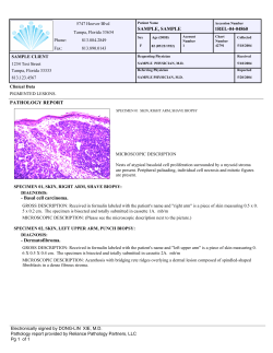


© Copyright 2026