
Installation Manual - Quick Reference Guide SMA FLEXIBLE STORAGE SYSTEM
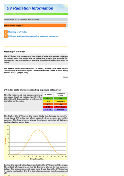
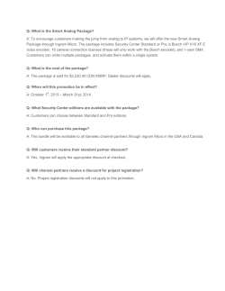
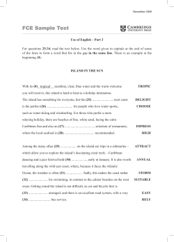
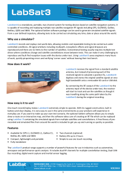
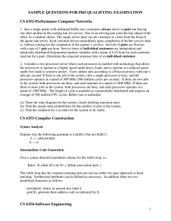
Installation Manual - Quick Reference Guide
SMA FLEXIBLE STORAGE SYSTEM
Increased Self-Consumption with SUNNY ISLAND and SUNNY HOME MANAGER
FSS-IAS-en-31 | Version 3.1
ENGLISH
Legal Provisions
SMA Solar Technology AG
Legal Provisions
The information contained in this document is the property of SMA Solar Technology AG. Publishing its content, either
partially or in full, requires the written permission of SMA Solar Technology AG. Any internal company copying of the
document for the purposes of evaluating the product or its correct implementation is allowed and does not require
permission.
SMA Warranty
You can download the current warranty conditions from the Internet at www.SMA-Solar.com.
Trademarks
All trademarks are recognized, even if not explicitly identified as such. A lack of identification does not mean that a
product or symbol is not trademarked.
The Bluetooth® word mark and logos are registered trademarks owned by Bluetooth SIG, Inc. and any use of these marks
by SMA Solar Technology AG is under license.
Modbus® is a registered trademark of Schneider Electric and is licensed by the Modbus Organization, Inc.
QR Code is a registered trademark of DENSO WAVE INCORPORATED.
Phillips® and Pozidriv® are registered trademarks of Phillips Screw Company.
Torx® is a registered trademark of Acument Global Technologies, Inc.
SMA Solar Technology AG
Sonnenallee 1
34266 Niestetal
Germany
Tel. +49 561 9522-0
Fax +49 561 9522-100
www.SMA.de
E-mail: [email protected]
© 2004 to 2014 SMA Solar Technology AG. All rights reserved
2
FSS-IAS-en-31
Installation Manual - Quick Reference Guide
SMA Solar Technology AG
Table of Contents
Table of Contents
1
Information on this Document. . . . . . . . . . . . . . . . . . . . . . . . . . . . . . . . . . . . . . . . . . . . . . . . . . . . . 4
2
Safety . . . . . . . . . . . . . . . . . . . . . . . . . . . . . . . . . . . . . . . . . . . . . . . . . . . . . . . . . . . . . . . . . . . . . . . . 6
2.1 Intended Use . . . . . . . . . . . . . . . . . . . . . . . . . . . . . . . . . . . . . . . . . . . . . . . . . . . . . . . . . . . . . . . . . . . . . . . . . 6
2.2 Skills of Qualified Persons . . . . . . . . . . . . . . . . . . . . . . . . . . . . . . . . . . . . . . . . . . . . . . . . . . . . . . . . . . . . . . . 6
2.3 Safety Precautions . . . . . . . . . . . . . . . . . . . . . . . . . . . . . . . . . . . . . . . . . . . . . . . . . . . . . . . . . . . . . . . . . . . . . 7
3
Information and System Description . . . . . . . . . . . . . . . . . . . . . . . . . . . . . . . . . . . . . . . . . . . . . . . 9
3.1 Requirement of the "Forum Network Technology / Network Operation in the VDE (FNN)" . . . . . . . . . . . . . 9
3.2 System Information . . . . . . . . . . . . . . . . . . . . . . . . . . . . . . . . . . . . . . . . . . . . . . . . . . . . . . . . . . . . . . . . . . . . 10
3.3 System Description . . . . . . . . . . . . . . . . . . . . . . . . . . . . . . . . . . . . . . . . . . . . . . . . . . . . . . . . . . . . . . . . . . . . 11
4
System with One Sunny Island . . . . . . . . . . . . . . . . . . . . . . . . . . . . . . . . . . . . . . . . . . . . . . . . . . . 13
4.1 Circuitry Overview . . . . . . . . . . . . . . . . . . . . . . . . . . . . . . . . . . . . . . . . . . . . . . . . . . . . . . . . . . . . . . . . . . . . 13
4.2 Sunny Island Connection . . . . . . . . . . . . . . . . . . . . . . . . . . . . . . . . . . . . . . . . . . . . . . . . . . . . . . . . . . . . . . . 14
5
System with Three Sunny Island Inverters . . . . . . . . . . . . . . . . . . . . . . . . . . . . . . . . . . . . . . . . . . 16
5.1 Circuitry Overview . . . . . . . . . . . . . . . . . . . . . . . . . . . . . . . . . . . . . . . . . . . . . . . . . . . . . . . . . . . . . . . . . . . . 16
5.2 Master Connection . . . . . . . . . . . . . . . . . . . . . . . . . . . . . . . . . . . . . . . . . . . . . . . . . . . . . . . . . . . . . . . . . . . . 17
5.3 Slave 1 and Slave 2 Connection . . . . . . . . . . . . . . . . . . . . . . . . . . . . . . . . . . . . . . . . . . . . . . . . . . . . . . . . . 18
6
Connection of the Sunny Home Manager . . . . . . . . . . . . . . . . . . . . . . . . . . . . . . . . . . . . . . . . . . 20
7
Performing Basic Configuration of the Sunny Island . . . . . . . . . . . . . . . . . . . . . . . . . . . . . . . . . 21
8
Preparing Bluetooth Communication . . . . . . . . . . . . . . . . . . . . . . . . . . . . . . . . . . . . . . . . . . . . . . 26
9
Commissioning the SMA Flexible Storage System . . . . . . . . . . . . . . . . . . . . . . . . . . . . . . . . . . . 27
10 Contact . . . . . . . . . . . . . . . . . . . . . . . . . . . . . . . . . . . . . . . . . . . . . . . . . . . . . . . . . . . . . . . . . . . . . . 29
Installation Manual - Quick Reference Guide
FSS-IAS-en-31
3
1 Information on this Document
SMA Solar Technology AG
1 Information on this Document
Validity
This document is valid for the SMA Flexible Storage System with the following SMA products:
• HM-BT-10.GR2 (Sunny Home Manager) from firmware version 1.04
• SI6.0H-11 / SI8.0H-11 (Sunny Island) from firmware version 3.1
Content and Structure of the Document
This document summarizes the specific information for the installation of an SMA Flexible Storage System. Circuitry
overviews provide the basic principle of how a 9/ SMA Flexible Storage System is connected. The structure of the
document specifies the chronological sequence for configuration and commissioning. This document does not replace the
documentation of the individual products. You will find details and help in the event of difficulties in the documentation of
the respective product.
Target Group
This document is intended for qualified persons. Only persons with the appropriate qualifications are allowed to perform
the tasks described in this document (see Section 2.2 "Skills of Qualified Persons", page 6).
Additional Information
Links to additional information can be found at www.SMA-Solar.com:
Document title
Document type
SMA Smart Home
Planning Guidelines
Sunny Explorer
User Manual
SMA Bluetooth® Wireless Technology
Technical Description
®
SMA Bluetooth Wireless Technology in Practice
Technical Information
Symbols
Symbol
Explanation
'$1*(5
Indicates a hazardous situation which, if not avoided, will result in death or serious injury
:$51,1*
Indicates a hazardous situation which, if not avoided, can result in death or serious injury
&$87,21
Indicates a hazardous situation which, if not avoided, can result in minor or moderate injury
/05*$&
Indicates a situation which, if not avoided, can result in property damage
Information that is important for a specific topic or goal, but is not safety-relevant
4
☐
Indicates a requirement for meeting a specific goal
☑
Desired result
✖
A problem that might occur
FSS-IAS-en-31
Installation Manual - Quick Reference Guide
SMA Solar Technology AG
1 Information on this Document
Typographies
Typography
Usage
bold
Example
• Display messages
• Parameters
• Connect the grounding conductor to
AC 2Gen/Grid.
• Select the parameter 235.01 GnAutoEna
and set to Off.
• Terminals
• Slots
• Elements to be selected
• Elements to be entered
>
• Several elements that are to be
selected
• Select 600# Direct Access > Select
Number.
Nomenclature
Complete designation
Designation in this document
SMA Bluetooth® Wireless Technology
Bluetooth
Sunny Boy, Sunny Mini Central, Sunny Tripower
®
PV inverter
SMA radio-controlled socket with Bluetooth Wireless
Technology
SMA radio-controlled socket
SMA Speedwire
Speedwire
SMA Speedwire data module Sunny Island
Speedwire data module Sunny Island
SMA Speedwire/Webconnect data module
Speedwire data module
Installation Manual - Quick Reference Guide
FSS-IAS-en-31
5
2 Safety
SMA Solar Technology AG
2 Safety
2.1 Intended Use
The SMA Flexible Storage System supports increased self-consumption through the following measures:
• Intermediate storage of excess PV energy with Sunny Island
• Load control and PV system monitoring with Sunny Home Manager
The SMA Flexible Storage System does not form a battery backup grid in the event of utility grid failure (for installation
of a battery backup grid, see the Quick Reference Guide "Battery Backup Systems").
The SMA Flexible Storage System must only be used in those countries for which it is licensed or in those countries for
which it is approved by SMA Solar Technology AG and the grid operator. The grid configuration must be a TN or TT
system.
The SMA Flexible Storage System captures the grid feed-in and purchased electricity with an SMA Energy Meter only.
An SMA Energy Meter does not replace the energy meter of the electric utility company. The grid feed-in and the
purchased electricity are transmitted to one Sunny Island via Speedwire. Therefore, the Sunny Island must be fitted with
the Speedwire data module Sunny Island.
The Sunny Home Manager must not be installed in PV systems in which a Sunny WebBox is installed.
In the SMA Flexible Storage System, the Sunny Island uses lead-acid batteries or lithium-ion batteries for energy storage.
A fuse switch-disconnector (e.g. BatFuse) must be installed between the battery and the Sunny Island. For systems with
lead-acid batteries, you must ensure that the battery room is sufficiently ventilated (see battery manufacturer
documentation). If lithium-ion batteries are connected, the battery management of the lithium-ion battery must be
compatible with the Sunny Island (see the Planning Guidelines "SMA Smart Home" at www.SMA-Solar.com).
Three Sunny Island inverters can be connected to a three-phase cluster. A cluster is connected in parallel on the DC side
and a shared battery is connected. Only Sunny Island inverters of the same device type must be installed in a cluster.
More than one cluster cannot be connected.
The SMA Flexible Storage System can be installed at altitudes of up to 2,000 m above Mean Sea Level.
The following products must not be connected in the SMA Flexible Storage System:
• Sunny Island Charger or other DC charge controllers
• DC loads
The system must be installed as intended. Any use other than that described in the Intended Use section does not qualify
as appropriate.
The documentation supplied with the products are an integral part of the respective products. The documentation must
be read, adhered to and kept in a convenient place at all times
2.2 Skills of Qualified Persons
The work described in this document must be performed by qualified persons only. Qualified persons must have the
following skills:
• Training in how to deal with the dangers and risks associated with installing and using electrical devices and batteries
• Training in the installation and commissioning of electrical devices
• Knowledge of and adherence to the technical connection conditions, standards and directives applicable at the
installation location
• In systems where lithium-ion batteries are used, knowledge of how to handle lithium-ion batteries and deal with any
hazards involved in their transport, storage and disposal.
• Knowledge of and compliance with this document and the documentation relating to the products including all safety
precautions
6
FSS-IAS-en-31
Installation Manual - Quick Reference Guide
SMA Solar Technology AG
2 Safety
2.3 Safety Precautions
This section contains safety precautions that must be observed at all times when working on or with the
SMA Flexible Storage System. To prevent personal injury and property damage and to ensure long-term operation of the
SMA Flexible Storage System, read this section carefully and comply with the safety precautions at all times.
:$51,1*
Danger to life from electric shock due to live voltage
High voltages are present in the SMA Flexible Storage System. When covers (e.g. an enclosure lid) are removed, touch
contact with live components is possible, and this can result in death or serious injury due to electric shock.
• When carrying out any work on the electrical installation, wear suitable personal protective equipment.
• Before removing a cover, disconnect the relevant component from voltage sources (see documentation of the
relevant component).
Danger to life from electric shock due to damaged devices
Operating a damaged device can lead to hazardous situations that can result in death or serious injuries due to electric
shock.
• In all cases, only use devices when they are technically faultless and in an operationally safe state.
• Regularly check all devices for visible damage.
• Ensure that all safety equipment is freely accessible at all times.
• Make sure that all safety equipment is in good working order.
Danger to life due to explosive gases
Explosive gases may escape from the battery and cause an explosion. This can result in death or serious injury.
• Protect the battery environment from open flames, embers or sparks.
• Install, operate and maintain the battery in accordance with the manufacturer's specifications.
• Do not burn or heat the battery above the temperature permitted.
• Ensure that the battery room is sufficiently ventilated.
Chemical burns and poisoning due to battery electrolyte
If handled inappropriately, electrolyte from the battery can burn the eyes, respiratory system and skin, and emit toxic
fumes. This may result in blindness and serious chemical burns.
• Protect the battery enclosure against damage.
• Do not open or deform the battery.
• Whenever working on the battery, wear suitable personal protective equipment such as rubber gloves, apron,
rubber boots and goggles.
• Rinse acid splashes thoroughly with clear water and consult a doctor.
• Install, operate, maintain and dispose of the battery in accordance with the manufacturer's specifications.
Risk of injury due to short-circuit currents
Short-circuit currents in the battery can cause heat build-up and electric arcs. Burns or eye injuries due to flashes may
result.
• Remove watches, rings and other metal objects.
• Use insulated tools.
• Do not place tools or metal parts on the battery.
Installation Manual - Quick Reference Guide
FSS-IAS-en-31
7
2 Safety
SMA Solar Technology AG
/05*$&
Damage to the battery due to incorrect settings
Incorrect settings can lead to the premature aging of the battery. Settings of the parameters in the menu 220# Battery
influence the charging behavior of the Sunny Island.
• Ensure that the values recommended by the battery manufacturer are set for the battery (refer to the technical data
of the battery in the manufacturer documentation).
Destruction of devices due to electrostatic discharge (ESD)
If enclosure parts are removed, the devices (e.g. Sunny Island or PV inverter) can be damaged or destroyed if electronic
components or terminals are touched.
• Do not touch any electronic parts in open devices.
• Ground yourself before touching any terminals.
8
FSS-IAS-en-31
Installation Manual - Quick Reference Guide
SMA Solar Technology AG
3 Information and System Description
3 Information and System Description
3.1 Requirement of the "Forum Network Technology / Network Operation in
the VDE (FNN)"
The information below applies exclusively to systems that comply with the following:
• No more than one Sunny Island is connected in the SMA Flexible Storage System
• The grid operator stipulates compliance with the Technical Information "Connecting and operating storage units in
low voltage networks" published by the FNN. At present, only grid operators in Germany require compliance with
the Technical Information (status as of: June 2014).
In such systems, the Sunny Island must be connected to a line conductor being supplied by a single-phase PV inverter. If
there are only three-phase PV inverters connected in the system, the Sunny Island can be connected to any line conductor.
The requirements of the FNN technical information "Connecting and operating storage units in low voltage networks"
affect the discharging behavior of the Sunny Island. In systems with one Sunny Island and single-phase PV inverters,
the SMA Flexible Storage System reduces the maximum discharge power of the Sunny Island as required.
Example 1:
All PV inverters are single-phase and are feeding in asymmetrically
(Sunny Boy). The PV inverters are connected to one line conductor.
The Sunny Island must be connected to the line conductor into which
the PV inverters are feeding.
Example 2:
All PV inverters are single-phase and are feeding in asymmetrically
(Sunny Boy). PV inverters are connected to two line conductors.
The Sunny Island must be connected to a line conductor into which
a single-phase PV inverter is feeding. TIP: Connect the Sunny Island
to the line conductor being supplied with the least PV energy.
This will increase the control range for increased self-consumption.
Example 3:
All PV inverters are single-phase and are feeding in asymmetrically
(Sunny Boy). One PV inverter is connected to each line conductor.
The Sunny Island can be connected to any line conductor.
TIP: Connect the Sunny Island to the line conductor being supplied
with the least PV energy. This will increase the control range for
increased self-consumption.
Installation Manual - Quick Reference Guide
FSS-IAS-en-31
9
3 Information and System Description
SMA Solar Technology AG
Example 4:
All PV inverters are three-phase and are feeding in symmetrically
(Sunny Tripower).
The Sunny Island can be connected to any line conductor.
Example 5:
The PV system consists of three-phase PV inverters (Sunny Tripower)
and single-phase PV inverters (Sunny Boy). The PV system is feeding
in asymmetrically.
The Sunny Island must be connected to a line conductor into which
a single-phase PV inverter is feeding.
The PV system is not ideal for the SMA Flexible Storage System.
The Sunny Island can only discharge the battery if less than 4.6 kVA
are being fed in on the line conductor of the Sunny Island at the
point of interconnection.
3.2 System Information
Battery capacity recommendations
SMA Solar Technology AG recommends the following minimum battery capacities. The battery capacities apply for
a ten-hour electric discharge (C10).
• System with one Sunny Island: 100 Ah
• System with three Sunny Island inverters: 300 Ah
Sunny Island terminals
At terminal AC2, there are two terminals N and NTT for the connection of the neutral conductor.
• Always connect the neutral conductor to the NTT terminal at the AC2 terminal in systems for increased
self-consumption.
This ensures that the Sunny Island disconnects at all poles.
Device types within a cluster
All Sunny Island inverters must be of the same device type.
Requirements of the router and the network switch
• All Speedwire devices must be connected to the same router or network switch.
• The router or network switch must support Multicast.
• The router must support "Internet Enabled Devices" with the interfaces SIP and STUN.
The most common routers and network switches support Multicast and "Internet Enabled Devices".
10
FSS-IAS-en-31
Installation Manual - Quick Reference Guide
SMA Solar Technology AG
3 Information and System Description
3.3 System Description
The SMA Flexible Storage System supports increased self-consumption through the following measures:
• Intermediate storage of excess PV energy with Sunny Island
• Load control and PV system monitoring with Sunny Home Manager
The Sunny Island uses the connected battery for the intermediate storage of excess PV energy. The
SMA Flexible Storage System captures the grid feed-in and the purchased electricity with the SMA Energy Meter.
The SMA Flexible Storage System uses this data to regulate the charging and discharging of the battery. The grid feed-in
and the purchased electricity are transmitted to the Sunny Island via Speedwire. Therefore, the Sunny Island must be fitted
with the Speedwire data module Sunny Island.
The Sunny Home Manager receives location-based weather forecasts via the Internet and uses these to create a yield
forecast for the PV system. In addition, the Sunny Home Manager determines how much energy is typically consumed in
a household at different times of the day and uses this to create a load profile of the household. The
Sunny Home Manager uses the yield forecast and the load profile to determine favorable times for increased
self-consumption and selectively switches, for example, the electrical loads connected to the SMA radio-controlled
sockets on and off. If required by the grid operator, the Sunny Home Manager also monitors the active power feed-in of
the PV system. If the set maximum value for active power feed-in is exceeded, the Sunny Home Manager sends power
reduction commands to the SMA PV inverters. The PV system can consist of PV inverters with Bluetooth communication
and PV inverters with Speedwire communication.
Prevention of Derating Losses
The SMA Flexible Storage System prevents derating losses which may arise due to the limitation of active power feed-in.
This is achieved by regulating the operation times of time-independent loads and the time and duration of battery
charging in accordance with the PV production forecast and the consumption forecast.
Example: The current daily forecast for the system predicts a limitation of active power feed-in around noon when the
energy requirement of the loads is very low and PV production is high. As a result, derating losses are to be expected.
According to this forecast, the system only begins to charge the battery in the late morning. The derating losses will be
reduced or avoided by charging the battery at this later time. The total excess PV energy generated in the morning will
be fed into the utility grid without derating losses (for details on power derating, see planning guidelines of
SMA Smart Home).
Required firmware of the Sunny Home Manager
As of firmware version 1.10, the Sunny Home Manager supports the prevention of derating losses by deferring the
charging of the battery to a later time. Firmware version 1.10 is scheduled to be available as of August 2014.
Installation Manual - Quick Reference Guide
FSS-IAS-en-31
11
3 Information and System Description
SMA Solar Technology AG
Optimized Discharging Behavior for Lead-Acid Batteries
The service life of a lead-acid battery is heavily dependent on the battery state of charge. The longer a lead-acid battery
remains charged, the longer the battery will last. The SMA Flexible Storage System prolongs the time in which the battery
remains charged. To do this, the Sunny Home Manager uses the calculated load profile and the PV production forecast
to control battery discharge. The battery is discharged when the following criteria are met:
• It is possible for the battery to be discharged to a point where sufficient storage capacity is free to absorb the forecast
amount of PV energy for the next battery charge.
• The discharged lead-acid battery can soon be charged with excess PV energy.
By utilizing these criteria, the SMA Flexible Storage System conserves the lead-acid battery while making optimum use
of the battery capacity. Therefore, the lead-acid battery is not always discharged directly in the evening, but only in the
morning hours.
Required firmware of the Sunny Home Manager
As of firmware version 1.10, the Sunny Home Manager supports the optimized discharging behavior of lead-acid
batteries in the SMA Flexible Storage System. Firmware version 1.10 is scheduled to be available from August
2014.
Deactivation of the Intermediate Storage of PV Energy during Certain Charging Procedures
To increase the service life of the battery, the SMA Flexible Storage System regularly carries out full and equalization
charges (see the Technical Information "Battery Management" at www.SMA-Solar.com). During this charging process,
the intermediate storage of PV energy is deactivated and electricity may have to be purchased to perform the full and
equalization charges.
12
FSS-IAS-en-31
Installation Manual - Quick Reference Guide
SMA Solar Technology AG
4 System with One Sunny Island
4 System with One Sunny Island
4.1 Circuitry Overview
Figure 1:
Circuitry of the SMA Flexible Storage System for TN and TT systems
Installation Manual - Quick Reference Guide
FSS-IAS-en-31
13
4 System with One Sunny Island
SMA Solar Technology AG
4.2 Sunny Island Connection
Figure 2:
Connection of the Sunny Island
Position
Designation
Description / information
A
AC power cable
Terminal AC2 Gen/Grid, terminals L, NTT und PE
Utility grid connection with a three-wire cable,
conductor cross-section: 6 mm² to 16 mm²
B
Grounding conductor
Terminal AC1 Loads/SunnyBoys, terminal PE
Additional grounding if the conductor cross-section of the AC power
cable is less than 10 mm².
The conductor cross-section must be at least that of the conductor
cross-section of the AC power cable.
C
DC+ cable
Battery connection
D
DC − cable
Conductor cross-section: 50 mm² to 95 mm²
E
Measuring cable of the battery
temperature sensor
Terminal BatTmp
Data cable to the
Sunny Remote Control
Terminal Display
F
14
FSS-IAS-en-31
You only have to connect a battery temperature sensor if lead-acid
batteries are used. The battery temperature sensor must be mounted in
the middle of the battery storage system, in the upper third of the
battery cell.
Installation Manual - Quick Reference Guide
SMA Solar Technology AG
4 System with One Sunny Island
Position
Designation
Description / information
G
Speedwire network cable
Terminal ComETH
In order to connect the router/network switch, the Speedwire data
module Sunny Island must be connected to the terminal ComETH in
the Sunny Island (see installation manual of the Speedwire data
module Sunny Island).
H
Data cable to the lithium-ion
battery
Installation Manual - Quick Reference Guide
Terminal ComSync In
Connection of the battery management of the lithium-ion battery
The communication bus must be connected to the lithium-ion battery
and the terminator must remain plugged into the terminal
ComSync Out.
FSS-IAS-en-31
15
5 System with Three Sunny Island Inverters
SMA Solar Technology AG
5 System with Three Sunny Island Inverters
5.1 Circuitry Overview
Figure 3:
16
SMA Flexible Storage System for TN and TT systems
FSS-IAS-en-31
Installation Manual - Quick Reference Guide
SMA Solar Technology AG
5 System with Three Sunny Island Inverters
5.2 Master Connection
Figure 4:
Connection of the master
Position
Designation
Description / information
A
AC power cable
Terminal AC2 Gen/Grid, terminals L, NTT und PE
Utility grid connection with a three-wire cable to the line conductor L1
Conductor cross-section: 6 mm² to 16 mm²
B
Grounding conductor
Terminal AC1 Loads/SunnyBoys, terminal PE
Additional grounding if the conductor cross-section of the AC power
cable is less than 10 mm².
The conductor cross-section must be at least that of the AC power
cable conductor cross-section.
C
DC+ cable
Battery connection
D
DC − cable
Conductor cross-section: 50 mm² to 95 mm²
E
Measuring cable of the battery
temperature sensor
Terminal BatTmp
Data cable to the
Sunny Remote Control
Terminal Display
F
Installation Manual - Quick Reference Guide
You only have to connect a battery temperature sensor if lead-acid
batteries are used. The battery temperature sensor must be mounted in
the middle of the battery storage system, in the upper third of the
battery cell.
FSS-IAS-en-31
17
5 System with Three Sunny Island Inverters
SMA Solar Technology AG
Position
Designation
Description / information
G
Speedwire network cable
Terminal ComETH
In order to connect the router/network switch, the Speedwire data
module Sunny Island must be connected to the terminal ComETH in
the Sunny Island (see installation manual of the Speedwire data
module Sunny Island).
H
Data cable to the lithium-ion
battery
Terminal ComSync In
Connection of the battery management of the lithium-ion battery
The communication bus must be connected to the lithium-ion battery.
If no lithium-ion batteries are used, plug the terminator into terminal
ComSync In.
I
Data cable for internal
communication in the cluster
Terminal ComSync Out
Connection of the internal communication bus of slave 1
5.3 Slave 1 and Slave 2 Connection
Figure 5:
Connection of the Sunny Island
Position
Designation
Description / information
A
AC power cable
Terminal AC2 Gen/Grid, terminals L, NTT und PE
Utility grid connection with a three-wire cable
Connect slave 1 to line conductor L2, connect slave 2 to line conductor
L3. Conductor cross-section: 6 mm² to 16 mm²
18
FSS-IAS-en-31
Installation Manual - Quick Reference Guide
SMA Solar Technology AG
5 System with Three Sunny Island Inverters
Position
Designation
Description / information
B
Grounding conductor
Terminal AC1 Loads/SunnyBoys, terminal PE
Additional grounding if the conductor cross-section of the AC power
cable is less than 10 mm². The conductor cross-section must be at least
that of the conductor cross-section of the AC power cable.
C
DC+ cable
Battery connection
D
DC − cable
Conductor cross-section: 50 mm² to 95 mm²
E
Data cable for internal
communication in the cluster
Terminal ComSync In
Data cable for internal
communication in the cluster
Terminal ComSync Out
F
Installation Manual - Quick Reference Guide
For slave 1, connection of the internal communication bus from the
master
For slave 2, connection of the internal communication bus from slave 1
For slave 1, connection of the internal communication bus to slave 2
For slave 2, leave the terminator plugged in. Slave 2 is only connected
to slave 1.
FSS-IAS-en-31
19
6 Connection of the Sunny Home Manager
SMA Solar Technology AG
6 Connection of the Sunny Home Manager
Figure 6:
Connection of the Sunny Home Manager
Requirements:
☐ All Speedwire devices must be connected to the same router or network switch.
☐ The router or network switch must support Multicast.
☐ The router must support "Internet Enabled Devices" with the interfaces SIP and STUN.
The most common routers and network switches support Multicast and "Internet Enabled Devices".
20
FSS-IAS-en-31
Installation Manual - Quick Reference Guide
SMA Solar Technology AG
7 Performing Basic Configuration of the Sunny Island
7 Performing Basic Configuration of the Sunny Island
:$51,1*
Danger to life due to fire or explosion
Danger of fire due to a lithium-ion battery that is incompatible with the Sunny Island. With incompatible lithium-ion
batteries, it is not ensured that the battery management will protect the battery.
• Ensure that the battery is from one of the following manufacturers and has been approved for Sunny Island by the
manufacturer:
– Akasol
– Dispatch Energy
– LG Chem
– Leclanché
– SAFT
– Samsung
– Sony
This list is updated regularly (see the Planning Guidelines "SMA Smart Home" at www.SMA-Solar.com).
/05*$&
Damage to the battery due to incorrect settings
The battery parameters influence the charging behavior of the Sunny Island. The battery will be damaged by incorrect
settings of the parameters for battery type, nominal voltage and battery capacity.
• Ensure that the values recommended by the battery manufacturer are set for the battery during basic configuration
(refer to the technical data of the battery in the manufacturer documentation).
• In the basic configuration, configure the battery capacity for a ten-hour electric discharge (C10). The battery
manufacturer specifies the battery capacity in relation to discharge time.
Requirements:
☐ The SMA Flexible Storage System must be installed in accordance with the circuitry (see Section 4 and Section 6).
☐ In a three-phase system, the Sunny Remote Control must be connected to the master. Thus, the master will be
determined during the basic configuration.
☐ The circuit breaker F1 in the distribution board must be open.
Procedure:
Check the wiring (see the Sunny Island installation manual).
Close all devices except the BatFuse.
This ensures that all voltage-carrying components are protected against contact.
Installation Manual - Quick Reference Guide
FSS-IAS-en-31
21
7 Performing Basic Configuration of the Sunny Island
SMA Solar Technology AG
Close the BatFuse and switch on all Sunny Island inverters:
in systems with one Sunny Island, press the "On" button.
For systems with three Sunny Island inverters,
press and hold the "On" button on the master until an acoustic signal sounds.
When the Sunny Remote Control shows <Init System>,
press and hold the button on the Sunny Remote Control.
☑ An acoustic signal sounds three times and the
Sunny Remote Control displays the
Quick Configuration Guide.
Turn the button on the Sunny Remote Control and select
New System.
Press the button. This sets the selection New System.
☑ An entry confirmation prompt appears.
Set Y and press the button.
22
FSS-IAS-en-31
Installation Manual - Quick Reference Guide
SMA Solar Technology AG
7 Performing Basic Configuration of the Sunny Island
Set the date.
Set the time.
Set OnGrid.
Set the battery type.
LiIon_Ext-BMS: lithium-ion battery
VRLA: lead-acid battery with electrolyte absorbed in glass
mat or immobilized in gel
FLA: lead-acid battery with liquid electrolyte
Set the battery capacity for ten-hour electric discharge
(for determining the battery capacity, see the Sunny Island
installation manual).
Set the battery nominal voltage.
Set the battery capacity for ten-hour electric discharge
(for determining the battery capacity, see the Sunny Island
installation manual).
Installation Manual - Quick Reference Guide
FSS-IAS-en-31
23
7 Performing Basic Configuration of the Sunny Island
SMA Solar Technology AG
In addition, set the country data set in the first ten operating
hours:
VDE-AR-4105: thresholds of the AC terminals correspond to the application directive VDE-AR-N 4105.
AS4777: thresholds correspond to the standard AS4777.
Ensure that the function SelfConsOnly is set.
Set the number of Sunny Island inverters in the system:
1Phase: System with 1 Sunny Island
3Phase: System with
3 Sunny Island
If the country data set of the Sunny Island is VDE-AR-4105, If the country data set of the
set the type of feed-in for the PV system
Sunny Island is AS4777,
(see Section 3.1, page 9).
confirm the basic
configuration with Y.
Confirm the basic
configuration with Y.
Asymmetric: The
Symmetric: The installation
installation site is located in site is either located outside
Germany and at least one PV
of Germany or all PV
inverter feeds in
inverters feed in
asymmetrically on a single symmetrically on three line
line conductor.
conductors.
Configure the line conductor
to which the Sunny Island is
connected:
Confirm the basic
configuration with Y.
Wait until the upper LED
(inverter LED) on slave 1 is
flashing and the
Sunny Remote Control shows
the message To identify
Slave1 press Tss on the
Slv.
L1: connection to line
conductor L1
L2: connection to line
conductor L2
L3: connection to line
conductor L3
24
FSS-IAS-en-31
Installation Manual - Quick Reference Guide
SMA Solar Technology AG
7 Performing Basic Configuration of the Sunny Island
Confirm the basic
configuration with Y.
Press the start-stop button on
slave 1.
Wait until the upper LED
(inverter LED) on slave 2 is
flashing and the Sunny
Remote Control shows the
message To identify
Slave2 press Tss on the
Slv.
Press the start-stop button on
slave 2.
☑ The basic configuration is complete.
If an SD memory card is inserted in the Sunny Remote Control,
the message Do not remove MMC/SD card ... appears.
Close the circuit breaker F1 and the residual-current device F2 in the distribution board
and leave the Sunny Island switched on, but do not start it.
Installation Manual - Quick Reference Guide
FSS-IAS-en-31
25
8 Preparing Bluetooth Communication
SMA Solar Technology AG
8 Preparing Bluetooth Communication
To enable communication between SMA Bluetooth devices in the SMA Flexible Storage System, all devices must be set
to the same NetID (identification number for SMA Bluetooth network). Systems with SMA Bluetooth operating in close
proximity to one another are distinguished by their individual NetID.
Procedure:
1. For PV inverters with integrated Bluetooth interface that communicate via Speedwire, set the NetID to 0
(see PV inverter installation manual). This deactivates communication via Bluetooth.
2. Determine the NetID of the Bluetooth PV system.
• Install Sunny Explorer on a computer. Either run the installation file on the CD provided or download free of
charge at www.SMA-Solar.com.
• Determine a free NetID for the Bluetooth PV system using Sunny Explorer (see Sunny Explorer user manual).
• Quit Sunny Explorer. This will ensure that the Bluetooth network is set up via the Sunny Home Manager.
3. Set the determined NetID on the Sunny Home Manager and on all
devices with active Bluetooth interface (see documentation of the
Bluetooth devices). Note that the NetID must not be set to 1 if the
Sunny Home Manager is intended to communicate with more than
one Bluetooth node.
26
FSS-IAS-en-31
Installation Manual - Quick Reference Guide
SMA Solar Technology AG
9 Commissioning the SMA Flexible Storage System
9 Commissioning the SMA Flexible Storage System
Data necessary for registration in Sunny Portal:
Device/customer data Necessary data and explanation
Sunny Home Manager
• Serial number (PIC) and registration ID (RID)
Register the new PV system in Sunny Portal using the PIC and RID.
SMA Energy Meter
• Only if two SMA Energy Meters are installed, note down the serial number and
purpose (e.g. PV production meter) in each case. This allows you to identify the energy
meters in Sunny Portal.
PV inverter
• PV system password
The PV system password is the same as the device password for the "Installer" user
group. All devices in a PV system must be set to the same password (for user groups
and security concept, see the Sunny Explorer user manual). The default password is
1111.
• Serial number of the PV inverters
You can uniquely identify the PV inverters in Sunny Portal via the serial number.
• PV array power in kWp
SMA radio-controlled
socket
• Serial number of each SMA radio-controlled socket and the loads connected
Customer data
• E-mail address
In Sunny Portal, configure the SMA radio-controlled socket in accordance with the
requirements of the connected load. You require the serial number of the
SMA radio-controlled socket.
• Password for Sunny Portal access
• Address of the PV system
• Electricity tariff data
– Electricity price for purchased electricity
– Tariff times, if applicable (e.g., for tariffs with peak and off-peak tariff)
– Feed-in tariff
– Self-consumption tariff, if applicable
Requirements:
☐ The SMA Flexible Storage System must be installed in accordance with the circuitry overviews.
☐ The Sunny Home Manager, the Sunny Island and all other Speedwire devices must be connected to the same router
or network switch.
☐ The basic configuration of the Sunny Island must have been performed (see Section 7).
☐ DHCP must be enabled on the router of the PV system.
☐ The router of the PV system must have an Internet connection.
Installation Manual - Quick Reference Guide
FSS-IAS-en-31
27
9 Commissioning the SMA Flexible Storage System
SMA Solar Technology AG
Procedure:
1. Switch on the circuit breaker F1 and the residual-current devices F2 in the distribution board.
2. Commission the PV system (see PV inverter documentation).
3. Press and hold the "On" button on the Sunny Island until an acoustic
signal sounds. This starts the system.
4. Only when two SMA Energy Meters are installed in the local network, assign the feed-in meter and purchased
electricity meter to the Sunny Island using Sunny Explorer. Enter the serial number of the feed-in meter and purchased
electricity meter (see Sunny Explorer user manual).
5. Open Sunny Portal via www.SunnyPortal.com/Register and run the PV System Setup Assistant. The required data
for registration in Sunny Portal must be at hand.
Representation of the Sunny Island inverters in Sunny Portal
The Sunny Island inverters will be displayed as one device in Sunny Portal, even if the system consists of three
Sunny Island inverters. The data is added together in systems with three Sunny Island inverters.
6. Activate the automatic update of the Sunny Home Manager and the PV system in Sunny Portal.
7. Only in systems with active power feed-in limitation, ensure that the limitation of the active power feed-in is configured
and functioning in Sunny Portal ("Configuring Active Power Feed-In Limitation" see the User Manual
"Sunny Home Manager in Sunny Portal" at www.SunnyPortal.com).
28
FSS-IAS-en-31
Installation Manual - Quick Reference Guide
SMA Solar Technology AG
10 Contact
10 Contact
If you have technical problems concerning our products, contact the SMA Service Line. We require the following
information in order to provide you with the necessary assistance:
• Displayed error message
• Type, serial number and firmware version of the Sunny Island inverters
• Type, rated capacity and nominal voltage of the connected battery
• Type, serial number, firmware version or software version of the communication products connected
• Type, serial number and firmware version of the PV inverters
Australia
SMA Australia Pty Ltd.
Toll free for Australia:
1800 SMA AUS
(1800 762 287)
International:
+61 2 9491 4200
Sydney
Belgien/
Belgique/
België
SMA Benelux BVBA/SPRL
Brasil
Vide España (Espanha)
Česko
SMA Central & Eastern Europe s.r.o.
+32 15 286 730
Mechelen
+420 235 010 417
Praha
Chile
Ver España
Danmark
Se Deutschland (Tyskland)
Deutschland
SMA Solar Technology AG
Medium Power Solutions
Niestetal
Wechselrichter:
+49 561 9522-1499
Kommunikation:
+49 561 9522-2499
SMA Online Service Center: www.SMA.de/Service
Hybrid Energy Solutions
Sunny Island:
+49 561 9522-399
PV-Diesel Hybridsysteme:
+49 561 9522-3199
Power Plant Solutions
Sunny Central:
España
France
+49 561 9522-299
SMA Ibérica Tecnología Solar, S.L.U.
Llamada gratuita en España: 900 14 22 22
Barcelona
Internacional:
SMA France S.A.S.
Medium Power Solutions
Lyon
Onduleurs :
Communication :
+34 902 14 24 24
+33 472 09 04 40
+33 472 09 04 41
Hybrid Energy Solutions
Sunny Island :
+33 472 09 04 42
Power Plant Solutions
Sunny Central :
India
SMA Solar India Pvt. Ltd.
+33 472 09 04 43
+91 22 61713888
Mumbai
Installation Manual - Quick Reference Guide
FSS-IAS-en-31
29
10 Contact
SMA Solar Technology AG
Italia
SMA Italia S.r.l.
+39 02 8934-7299
Milano
Κύπρος/
Kıbrıs
Βλέπε Ελλάδα/
Bkz. Ελλάδα (Yunanistan)
Luxemburg/
Luxembourg
Siehe Belgien/
Voir Belgien (Belgique)
Magyarország
lásd Česko (Csehország)
Nederland
zie Belgien (België)
Österreich
Siehe Deutschland
Perú
Ver España
Polska
Patrz Česko (Czechy)
Portugal
SMA Solar Technology Portugal,
Unipessoal Lda
Lisboa
Isento de taxas em Portugal: 800 20 89 87
Internacional:
+351 2 12 37 78 60
România
Vezi Česko (Cehia)
Schweiz
Siehe Deutschland
Slovensko
pozri Česko (Česká republika)
South Africa
SMA Solar Technology
South Africa Pty Ltd.
08600 SUNNY
(08600 78669)
Centurion (Pretoria)
International:
United Kingdom SMA Solar UK Ltd.
+27 (12) 643 1785
+44 1908 304899
Milton Keynes
Ελλάδα
България
SMA Hellas AE
801 222 9 222
Αθήνα
International:
+30 212 222 9 222
Вижте Ελλάδα (Гърция)
대한민국
SMA Solar (Thailand) Co., Ltd.
+66 2 670 6999
SMA Technology Korea Co., Ltd.
+82 2 508-8599
서울
中国
SMA Beijing Commercial Company
Ltd.
+86 10 5670 1350
北京
+971 2 234-6177
SMA Middle East LLC
Other countries
International SMA Service Line
Niestetal
30
FSS-IAS-en-31
!
Toll free worldwide: 00800 SMA SERVICE
(+800 762 7378423)
Installation Manual - Quick Reference Guide
SMA Solar Technology
www.SMA-Solar.com


© Copyright 2026