
HC900 Process & Safety Controller Safety Manual Doc. No.:
HC900 Process & Safety Controller Safety Manual Doc. No.: 51-52-25-153 Revision: 1.9 Date: January 2014 Notices and Trademarks Copyright 2014 by Honeywell Revision 1.9 January 2014 Warranty/Remedy Honeywell warrants goods of its manufacture as being free of defective materials and faulty workmanship. Contact your local sales office for warranty information. If warranted goods are returned to Honeywell during the period of coverage, Honeywell will repair or replace without charge those items it finds defective. The foregoing is Buyer's sole remedy and is in lieu of all other warranties, expressed or implied, including those of merchantability and fitness for a particular purpose. Specifications may change without notice. The information we supply is believed to be accurate and reliable as of this printing. However, we assume no responsibility for its use. While we provide application assistance personally, through our literature and the Honeywell web site, it is up to the customer to determine the suitability of the product in the application. Honeywell Process Solutions 512 Virginia Drive Fort Washington, PA 19034 Honeywell is a U.S. registered trademark of Honeywell Other brand or product names are trademarks of their respective owners. ii HC900 Process & Safety Controller Safety Manual Revision 1.9 01/14 About This Document Abstract The Safety Manual provides information about HC900 that is relevant for integration into a Safety Instrumented System (SIS). References The following list identifies all documents that may be sources of reference for material discussed in this publication. Document Title ID # HC900 Process & Safety Controller Installation and User guide 51-52-25-154 HC900 Process Controller Technical Overview Specification 51-52-03-31 HC900 Module Specification 51-52-03-41 Process Control Designer Specification 51-52-03-43 HC900 Process Control Designer User Guide 51-52-25-110 HC900 Process Control Utilities User Guide 51-52-25-126 HC900 Process Controller Function Block Reference Guide 51-52-25-109 HC900 Process Controller Communications User Guide 51-52-25-111 HC900 Controller Redundancy Overview & System Operation 51-52-25-133 900 Control Station For use with HC900 Process Controller 51-52-25-148 Station Designer Software manual 51-52-25-149 IEC 61508 (2010) - External document N/A IEC 61511 (2004) External document N/A Revision Information Document Name Revision Number Publication Date 51-52-25-153 HC900 Process & Safety Controller Safety Manual Revision 1.9 January 2014 Revision 1.9 01/14 HC900 Process & Safety Controller Safety Manual iii Support and Contact Information For Europe, Asia Pacific, North and South America contact details, refer to the back page of this manual or the appropriate Honeywell Solution Support web site: Honeywell Organization WWW Address (URL) Corporate http://www.honeywell.com Honeywell Process Solutions www.honeywellprocess.com HPS Technical tips https://www.honeywellprocess.com/enUS/explore/products/control-monitoring-and-safetysystems/scalable-control-solutions/hc900-controlsystem/Pages/hc900-controller.aspx Telephone and Email Contacts Area United States and Canada Organization Phone Number 1-800-343-0228 Customer Service 1-800-423-9883 Global Technical Support Honeywell Inc. Email: (Sales) Global Email Support Honeywell Process Solutions [email protected] or (TAC) [email protected] iv HC900 Process & Safety Controller Safety Manual Revision 1.9 01/14 Symbol Definitions The following table lists those symbols that may be used in this document and on the product to denote certain conditions. Symbol Definition This DANGER symbol indicates an imminently hazardous situation, which, if not avoided, will result in death or serious injury. This WARNING symbol indicates a potentially hazardous situation, which, if not avoided, could result in death or serious injury. This CAUTION symbol may be present on Control Product instrumentation and literature. If present on a product, the user must consult the appropriate part of the accompanying product literature for more information. This CAUTION symbol indicates a potentially hazardous situation, which, if not avoided, may result in property damage. WARNING PERSONAL INJURY: Risk of electrical shock. This symbol warns the user of a potential shock hazard where HAZARDOUS LIVE voltages greater than 30 Vrms, 42.4 Vpeak, or 60 Vdc may be accessible. Failure to comply with these instructions could result in death or serious injury. ATTENTION, Electrostatic Discharge (ESD) hazards. Observe precautions for handling electrostatic sensitive devices CAUTION, HOT SURFACE: This symbol warns the user of potential hot surfaces which should be handled with appropriate caution. Protective Earth (PE) terminal. Provided for connection of the protective earth (green or green/yellow) supply system conductor. Functional earth terminal. Used for non-safety purposes such as noise immunity improvement. NOTE: This connection shall be bonded to protective earth at the source of supply in accordance with national and local electrical code requirements. Earth Ground. Functional earth connection. NOTE: This connection shall be bonded to Protective earth at the source of supply in accordance with national and local electrical code requirements. Chassis Ground. Identifies a connection to the chassis or frame of the equipment shall be bonded to Protective Earth at the source of supply in accordance with national and local electrical code requirements. Revision 1.9 01/14 HC900 Process & Safety Controller Safety Manual v Terms and Abbreviations vi 1oo1 One out of one 2oo3 Two out of three Basic Safety The equipment must be designed and manufactured such that it protects against risk of damage to persons by electrical shock and other hazards and against resulting fire and explosion. The protection must be effective under all conditions of the nominal operation and under single fault condition DU Dangerous Undetected failures FMEDA Failure Modes, Effects and Diagnostic Analysis Functional Safety The ability of a system to carry out the actions necessary to achieve or to maintain a defined safe state for the equipment / machinery / plant / apparatus under control of the system GTS Global Technical Support Center HFT Hardware Fault Tolerance Low demand mode Mode, where the frequency of demands for operation made on a safety-related system is no greater than one per year and no greater than twice the proof test frequency. PFDAVG Average Probability of Failure on Demand Safety Freedom from unacceptable risk of harm Safety Assessment The investigation to arrive at a judgment - based on evidence - of the safety achieved by safety-related systems. Further definitions of terms used for safety techniques and measures and the description of safety related systems are given in IEC 61508-4. SFF Safe Failure Fraction, the fraction of the overall failure rate of a device that results in either a safe fault or a diagnosed unsafe fault. SIF Safety Instrumented Function, a set of equipment intended to reduce the risk due to a specific hazard (a safety loop). SIL Safety Integrity Level, discrete level (one out of a possible four) for specifying the safety integrity requirements of the safety functions to be allocated to the E/E/PE safety-related systems where Safety Integrity Level 4 has the highest level of safety integrity and Safety Integrity Level 1 has the lowest. SIS Safety Instrumented System – Implementation of one or more Safety Instrumented Functions. A SIS is composed of any combination of sensor(s), logic solver(s), and final element(s). HC900 Process & Safety Controller Safety Manual Revision 1.9 01/14 Contents The Safety Manual .......................................................................................................... 1 Scope ................................................................................................................................................. 1 Basic Skills and Knowledge ................................................................................................................ 1 Safety Standards for Process & Equipment Under Control (PUC, EUC) .............................................. 1 The IEC 61508 and IEC 61511 Standards .......................................................................................... 2 Introduction ..................................................................................................................... 5 System Overview................................................................................................................................ 5 HC900 Control System Architectures .............................................................................. 9 Introduction to the Hardware ............................................................................................................... 9 Non-Redundant Controller and Non-Redundant IO ........................................................................... 13 Redundant Controllers and Non-Redundant IO ................................................................................. 13 HC900 controller Features ................................................................................................................ 15 Scope of SIL Certification for HC900 Control System Architectures ................................................... 16 Design and Implementation of HC900 Control System ................................................. 17 Allowable Function Blocks for Process and Safety Functions ............................................................ 17 HC900 Control System Operational Modes ....................................................................................... 46 Hardware and wiring requirements for safety configuration................................................................ 46 HC900 Safety configurations............................................................................................................. 48 HC900 Control System Diagnostics .................................................................................................. 52 HC900 SIL Control System communications ..................................................................................... 53 HC900 system Start-up test .............................................................................................................. 54 HC900 PFD ................................................................................................................... 55 Probability of Failure on Demand (PFD) for Low Demand Mode ........................................................ 55 HC900 Control System Fault Detection and Response................................................. 57 Principle of Fault Detection and Response ........................................................................................ 57 Diagnostic Test Interval .................................................................................................................... 57 Fault Reaction and IO states............................................................................................................. 58 HC900 Controller Diagnostics ........................................................................................................... 59 HC900 SIL Compatibility ................................................................................................................... 59 Reliability data ............................................................................................................... 62 Revision 1.9 01/14 HC900 Process & Safety Controller Safety Manual vii Tables Table 1 – IEC 61508 versus IEC 61511 terminology ............................................................................................ 2 Table 2 – Descriptions of Major Components .................................................................................................... 10 Table 3 – Descriptions of Major Redundancy Components................................................................................. 12 Table 4 – Function Blocks ................................................................................................................................. 17 Table 5 – Status Indicators................................................................................................................................. 52 Table 6 – SIL Levels ......................................................................................................................................... 55 Table 7 – Diagnostic Test Intervals .................................................................................................................... 57 Figures Figure 1 – Small HC900 Controller Configuration ............................................................................................... 5 Figure 2 – Expanded HC900 Controller Configuration ......................................................................................... 6 Figure 3 – Single process with redundancies ........................................................................................................ 7 Figure 4 – Configuration with Multiple Controllers .............................................................................................. 9 Figure 5 – Redundant Configuration with multiple I/O racks .............................................................................. 11 Figure 6 – Two safety applications process with redundancies (C75 CPU only) .................................................. 14 Figure 7 – Analog Input Voting Block ............................................................................................................... 42 Figure 8 – Analog Output Validation Block ....................................................................................................... 43 Figure 9 – Digital Input Voting Block ................................................................................................................ 43 Figure 10 – Digital Output Validation Block ...................................................................................................... 43 Figure 11 – Fault Monitor Block ........................................................................................................................ 44 Figure 12 – IO-V function block connections .................................................................................................... 46 Figure 13 – Individual Series DO connections.................................................................................................... 47 Figure 14 – Common Series DO connections ..................................................................................................... 47 Figure 15 – Series Relay for Analog Outputs ..................................................................................................... 48 Figure 16 – Safety Dataflow .............................................................................................................................. 49 Figure 17 – Sample controlled start-up configuration ......................................................................................... 50 Figure 18 – Sample VFAIL qualification ........................................................................................................... 50 viii HC900 Process & Safety Controller Safety Manual Revision 1.9 01/14 The Safety Manual This manual is intended for users who have Honeywell HC900 product with SIL certification and intend to use it in SIF. Scope The Safety Manual provides information about HC900 that is relevant for integration into a Safety Instrumented System (SIS). This manual is aimed at technical personnel responsible for such integration. The Safety Manual is a reference guide providing detailed information regarding safety aspects in HC900. A reference guide is a HC900 related guide and does not describe tasks in terms of how to perform the task in terms of steps to follow. A reference guide can provide input to support decisions required to achieve a certain objective. Basic Skills and Knowledge Before you start work on the HC900 SIS it is assumed that you are certified to do work on safety related systems and devices, and that you have appropriate knowledge of: • The concepts and functioning of the HC900 • The applicable process and equipment under control within the SIS, • This Safety Manual, • Site procedures, • Applicable safety standards (e.g. IEC 61508 and IEC 61511) This guide assumes that you have a basic familiarity with the process(es) connected to the equipment under control and that you have a complete understanding of the hazard and risk analysis Safety Standards for Process & Equipment Under Control (PUC, EUC) Processes and Equipment Under Control (PUC/EUC) in the process industry require a high level of safety. Safety Instrumented Systems (SIS) are used to perform Safety Instrumented Functions (SIF). Instrumentation that is used for SIFs, must meet minimum standards and performance levels. Standards like IEC 61508 and IEC 61511 have been developed for this purpose. One of the performance criteria that these standards apply is the Safety Integrity Level (SIL). IEC 61508 details the design requirements for achieving the required SIL. The safety integrity requirements for each individual safety function may differ. The safety function and SIL requirements are derived from hazard analysis and risk assessments. The higher the level of adapted safety integrity, the lower the likelihood of dangerous failure of the SIS, These standards also address the safety-related sensors and final elements regardless of the technology used. The HC900 can be used in a specific SIF that demands SIL 1 or SIL 2. Only the HC900 portion of the EUC control system will be documented in this safety manual. HC900 can be used only in applications for Demand mode operation. Revision 1.9 01/14 HC900 Process & Safety Controller Safety Manual 1 The Safety Manual - The IEC 61508 and IEC 61511 Standards Safety Integrity Level (SIL) The IEC 61508 standard specifies 4 levels of safety performance for safety functions. These are called safety integrity levels. Safety integrity level 1 (SIL1) is the lowest level of safety integrity, and safety integrity level 4 (SIL4) the highest level. If the level is below SIL1, the IEC 61508 and IEC 61511 do not apply. HC900 can be used for processing multiple SIFs simultaneously demanding a SIL1 and SIL2. The IEC 61508 and IEC 61511 Standards SISs have been used for many years to perform safety instrumented functions e.g. in chemical, petrochemical and gas plants. In order for instrumentation to be effectively used for safety instrumented functions, it is essential that the instrumentation meets certain minimum standards and performance levels. To define the characteristics, main concepts and required performance levels, standards IEC 61508 and IEC 61511 have been developed. The introduction of Safety Integrity level (SIL) is one of the results of these standards. This brief provides a short explanation of each standard. Detailed information regarding IEC 61508 and 61511 can be found on the IEC web site, http://www.iec.org. What standard to use? • If you are in the process sector and you are an owner/user, it is strongly recommended that you pay attention to the IEC 61511 (ANSI/ISA 84.00.01). • If you are in the process sector and you are a manufacturer, it is strongly recommended that you pay attention to the IEC 61508. • If you are in another sector, it is strongly recommended that you look for, and use, your sector specific IEC standard for functional safety (if there is one). If none exists, you can use the IEC 61508 instead. IEC 61508 and IEC 61511 terminology This guide contains both IEC 61508 and IEC 61511 related terminology. As the IEC 61511 sits within the framework of IEC 61508 most of the terminology used may be interchanged. Table 1 below provides an overview of the most common interchangeable terminology. Table 1 – IEC 61508 versus IEC 61511 terminology IEC 61508 terminology IEC 61511 terminology safety function safety instrumented function electrical/electronic/programmable electronic (E/E/PE) safety-related system safety instrumented system (SIS) IEC 61508, the standard for all E/E/PE safety-related systems The IEC 61508 is called “Functional safety of electrical/electronic/programmable electronic safety-related systems” IEC 61508 covers all safety-related systems that are electrotechnical in nature (i.e. Electrical, Electronic and Programmable Electronic systems (E/E/PE) ). 2 HC900 Process & Safety Controller Safety Manual Revision 1.9 01/14 The Safety Manual - The IEC 61508 and IEC 61511 Standards Generic standard The standard is generic and is intended to provide guidance on how to develop E/E/PE safety related devices as used in Safety Instrumented Systems (SIS). The IEC 61508: • serves as a basis for the development of sector standards (e.g. for the machinery sector, the process sector, the nuclear sector, etc.) • can serve as stand-alone standard for those sectors where a sector specific standard does not exist. SIL IEC 61508 details the design requirements for achieving the required Safety Integrity Level (SIL). The safety integrity requirements for each individual safety function may differ. The safety function and SIL requirements are derived from the hazard analysis and the risk assessment. The higher the level of adapted safety integrity, the lower the likelihood of dangerous failure of the SIS. This standard also addresses the safety-related sensors and final elements regardless of the technology used. IEC 61511, the standard for the process industry The IEC 61511 is called “Functional safety - Safety instrumented systems for the process industry sector”. It is also referred to as the ANSI/ISA 84.00.01. This standard addresses the application of SISs for the process industries. It requires a process hazard and risk assessment to be carried out, to enable the specification for SISs to be derived. In this standard a SIS includes all components and subsystems necessary to carry out the safety instrumented function from sensor(s) to final element(s). The standard is intended to lead to a high level of consistency in underlying principles, terminology and information within the process industries. This should have both safety and economic benefits. The IEC 61511 sits within the framework of IEC 61508. For more information regarding, or help on, implementing or determining, the applied safety standards for your plant/process please contact your Honeywell affiliate. Our Safety Consultants can help you to: • perform a hazard risk analysis • determine the SIL requirements • design the Safety Instrumented System • validate and verify the design • train your local safety staff Revision 1.9 01/14 HC900 Process & Safety Controller Safety Manual 3 The Safety Manual - The IEC 61508 and IEC 61511 Standards This page is intentionally left blank. 4 HC900 Process & Safety Controller Safety Manual Revision 1.9 01/14 Introduction The Honeywell HC900 Process Controller is an integrated loop and logic controller that is designed specifically for small- and medium-scale unit operations. System Overview It comprises a set of hardware and software modules that can be assembled to satisfy any of a broad range of control applications. The HC900 Controller System can consist of a single rack, as indicated in Figure 1, or can be can be networked with other controllers via Ethernet links to expand the dimensions of process control over a wider range of unit processes, as indicated in Figure 2 . Figure 1 – Small HC900 Controller Configuration Revision 1.9 01/14 HC900 Process & Safety Controller Safety Manual 5 Introduction - System Overview Figure 2 – Expanded HC900 Controller Configuration The HC900 Controller design enables users and OEMs who are adept in system integration to assemble a system that fits a broad range of requirements. Any configuration can be readily modified or expanded as requirements dictate. In initial configuration and in subsequent modifications, the HC900 Controller affords an optimum balance of performance and economy. Configurations such as those shown in Figure 1 and in Figure 2, as well as many variations, can be assembled from modular components. Many of the components are available from Honeywell, and some are available from third-party suppliers. These modular components are available in any quantity and mix that make the most sense for a given application. As indicated in Figure 3, the HC900 Controller includes provisions for communication via Ethernet with host systems such as the Honeywell Experion HMI and other HMI software that supports Ethernet Modbus/TCP protocol. Also, the communication structure of the HC900 Controller enables remote placement of input/output components, allowing significant economies in cabling and wiring. 6 HC900 Process & Safety Controller Safety Manual Revision 1.9 01/14 Introduction - System Overview Figure 3 – Single process with redundancies Revision 1.9 01/14 HC900 Process & Safety Controller Safety Manual 7 Introduction - System Overview This page is intentionally left blank. 8 HC900 Process & Safety Controller Safety Manual Revision 1.9 01/14 HC900 Control System Architectures Refer to the following manuals for more details on the various HC900 control system architectures. Introduction to the Hardware The Honeywell HC900 Process Controller includes a set of hardware modules that can be combined and configured as required for a wide range of small to medium process control applications. Some of the modules are required in all configurations. Others are optional; they are selected as appropriate to provide optional functions and/or to "size" the system, either in initial planning, or in modifying and/or expanding the system to meet changing requirements. An HC900 Controller configuration with multiple controllers is illustrated in Figure 4. This illustration includes key-numbers that identify components that are described in Table 2. An HC900 Redundant Controller configuration with multiple I/O racks is illustrated in the below figure. Figure 5. This illustration includes key-numbers that identify components that are described in Table 3. Figure 4 – Configuration with Multiple Controllers Revision 1.9 01/14 HC900 Process & Safety Controller Safety Manual 9 HC900 Control System Architectures - Table 2 – Descriptions of Major Components Key No. Component Name Description 1 Controller (Local) Rack Includes: Rack, Power Supply, Controller Module, and I/O modules Honeywell 2 I/O Expansion Rack (C50S/C70S CPUs only) (Optional) Includes: Rack, Power Supply, Scanner Module, and I/O modules Honeywell 3 Operator Interface 900 Control Station operator interface communicates via Ethernet or RS-485 serial link Honeywell 4 PC Configuration Tool (Optional) PC (laptop or desktop) connects to RS-485 or Ethernet port(s) on any (one) Controller module. Includes Honeywell Designer Software (configuration software). PC & USB to RS485 convertors are from third-party suppliers. Configuration software is from Honeywell. 5 HMI (HumanMachine Interface) (Optional) PC link to Ethernet network, which may include other HMIs, other HC900 Controllers, and other networks (including Internet). PC is from third-party supplier. HMI software is available from Honeywell (PlantScape or SpecView32) or from third-party supplier. Typically includes HMI operating software. May also include Designer Software (configuration tool and utility software). 10 Source 6 Ethernet 100Base-T Switch Enables connection of the private Ethernet 100Base-T port on a (C50S/C70S CPU only) Controller Module to the (S50S) Scanner modules on 2, 3, or 4 I/O Expansion racks. (If a single I/O expansion rack is connected directly to a Controller Module, the Switch is not required.) Honeywell Qualified Switch from Honeywell or third- party suppliers 6a Ethernet 10/100Base-T Switch or Router Enables inter-connection of several 10/100Base-T Ethernet devices in an Ethernet network. Devices include other HC900 Controllers, HMIs, and can also include routers, brouters, servers, and other devices in wider networks. Third-party suppliers. 7 Shielded CAT5 Ethernet cable Connects I/O expansion racks (S50S only) to controllers (C50/C70 CPU only) and/or to 10/100baseT Ethernet switches. Honeywell or Thirdparty suppliers Fiber Optics Cable Controller to remote rack distance up to 750m (2460 ft.) with one fiber cable. Distances up to 1500m (4920 ft.) are possible with a fiber switch used as a repeater at the midpoint. 8 Shielded CAT5 Ethernet cable Connects devices in Ethernet Open Connectivity network to 900 Control Stations and PC SCADA applications. Honeywell or Thirdparty suppliers 10 RS-485 cable Shielded twisted pair cable connects Isolated Controller port to field devices or PC with RS-485 convertor Honeywell or Thirdparty suppliers HC900 Process & Safety Controller Safety Manual Revision 1.9 01/14 HC900 Control System Architectures - Redundancy Figure 5 – Redundant Configuration with multiple I/O racks Revision 1.9 01/14 HC900 Process & Safety Controller Safety Manual 11 HC900 Control System Architectures - Table 3 – Descriptions of Major Redundancy Components Key No. Component Name Description 1 Controller (Local) Rack Includes: Rack, 2 Power Supplies, 2 C75S Controllers, 1 Redundancy Switch Module (RSM) Honeywell 2 I/O Expansion Rack Includes: 1 S75S Scanner 2 module, 1 Power Supply, and up to 4, 8, or 12 I/O modules. Optional second Power Supply and Power Status Module (PSM) on 8- and 12-slot I/O racks. Honeywell 3 Operator Interface 900 Control Station operator interface communicates via Ethernet or RS-485 serial link Honeywell 4 PC Configuration Tool (Optional) PC (laptop or desktop) connects to RS-485 or Ethernet port(s) on any (one) LEAD Controller module. Includes Honeywell Designer Software (configuration software). PC & USB to RS485 convertors are from third-party suppliers. Configuration software is from Honeywell. 5 HMI (HumanMachine Interface) (Optional) PC link to Ethernet network, which may include other HMIs, other HC900 Controllers, and other networks (including Internet). PC is from third-party supplier. Typically includes HMI operating software. May also include Designer (configuration tool and utility software). HMI software is available from Honeywell (PlantScape or SpecView32) or from third-party supplier. 6 Ethernet 100Base-T Switch Required if using 2 or more I/O Expansion racks. Provides connection of the private I/O Ethernet 100Base-T port on a (C75S) Controller Module to the (S75S) Scanner modules. Switch not required for connection to a single I/O rack. Honeywell 6a Ethernet 10/100Base-T Switch or Router Enables inter-connection of several 10/100Base-T Ethernet devices in an Ethernet network. Devices include other HC900 Controllers, HMIs, and can also include routers, brouters, servers, and other devices in wider networks. Honeywell or thirdparty suppliers. 7 Shielded Ethernet CAT5 cable Connects I/O (S75S) expansion racks to (C75S) controllers and/or to 10/100baseT Ethernet switches. It also connects to 900 Control Stations and PC SCADA software applications. Honeywell or thirdparty suppliers. Fiber Optics Cable Controller to remote rack distance up to 750m (2460 ft.) with one fiber cable. Distances up to 1500m (4920 ft.) are possible with a fiber switch used as a repeater at the midpoint. RS-485 cable Shielded twisted pair cable connects Isolated Controller port to field devices or PC with RS-485 convertor 9 12 Source HC900 Process & Safety Controller Safety Manual Honeywell or Thirdparty suppliers Revision 1.9 01/14 HC900 Control System Architectures - Non-Redundant Controller and Non-Redundant IO Non-Redundant Controller and Non-Redundant IO The HC900 control system is an integrated loop and logic controller that is designed specifically for small- and medium-scale unit applications. It comprises a set of hardware and software modules that can be assembled to satisfy the requirement of any of a broad range of safety and process control applications. The HC900 control system can consist of a single rack, as indicated in Figure 1, it can be networked with other HC900 control systems via Ethernet links to expand the dimensions of control over a wider range of unit processes, as indicated in Figure 2, support a single process with redundancies, as indicated in Figure 3 or provide stand alone safety or mixed safety – process applications as shown in Figure 6. A feature summary list is provided after these topologies. The HC900 Controller design enables users and OEMs who are adept in safety system integration to assemble a safety system that fits a broad range of requirements. Any configuration can be readily modified or expanded as requirements dictate. In initial configuration and in subsequent modifications, the HC900 Controller affords an optimum balance of performance and economy. Configurations such as those shown in Figure 1 and Figure 2, as well as many variations, can be assembled from modular components. Many of the components are available from Honeywell, and some are available from thirdparty suppliers. These modular components are available in any quantity and mix that make the most sense for a given application. As indicated in Figure 3, the HC900 Controller includes provisions for communication via Ethernet with host systems such as the Honeywell Experion HMI and other HMI software that supports Ethernet Modbus/TCP protocol. Also, the communication structure of the HC900 Controller enables remote placement of input/output components, allowing significant economies in cabling and wiring. Redundant Controllers and Non-Redundant IO The following six components refer to: – Single process with redundancies (C75S CPU) only. • Redundant CPUs - Redundancy is provided by two C75S CPUs operating in a controller rack; this rack does not have I/O. A Redundancy switch module (RSM) sits between the CPUs. • Redundant CPU Power - Two power supplies, one for each C75S CPU. • Redundant CPU-I/O connection – Each CPU has its own 100 base-T Ethernet physical communication link with one or more racks of I/O. Multiple I/O racks require Ethernet switches. • I/O racks – 8-slot racks w/redundant power supplies are shown but four additional racks sizes /types are available, 4 – slot rack, 8- slot rack, 12-slot rack and 12-slot w/redundant power supplies. A Power Status Module (PSM) is required with the redundant power supplies rack. High and low capacity universal AC power supplies are available as well as a 24V DC Power Supply. • Redundant Networks for Host communications - Redundant Networks for Host communications are provided on the C75S CPU. Both network ports are continuously active on the Lead controller. The network ports on the Reserve CPU are not available for external communications. Experion HS and the 900 Control Station (15 inch model) support redundant Ethernet communications and automatically transfer communications during a network failure. • Scanner 2 (S75S) module – provides 2 ports, one for each CPU connection to I/O. • Process Applications can be run on the Safety system with separate process IO modules. Revision 1.9 01/14 HC900 Process & Safety Controller Safety Manual 13 HC900 Control System Architectures - Redundant Controllers and Non-Redundant IO Figure 6 – Two safety applications process with redundancies (C75 CPU only) 14 HC900 Process & Safety Controller Safety Manual Revision 1.9 01/14 HC900 Control System Architectures - HC900 controller Features HC900 controller Features Hardware • Modular rack structure; components are ordered individually as needed • CPU with Ethernet communications • Easy to assemble, modify, and expand • Local (C30S) and Remote input/output racks (C50S/C70S), private Ethernet-linked sub-network • Parallel processing - a microprocessor in each I/O module performs signal processing, to preserve update rates and proper failsafe action on loss of Controller updates. • Power supplies - provide power to CPU rack and Scanner I/O rack Redundancy (this will be available with the next release) • Redundant C75S CPU • Redundancy Switch Module (RSM) – required between redundant CPUs • Redundant Power Supply – provides redundant power to any CPU rack or Scanner2 I/O rack • Power Status Module (PSM) – required when using a second power supply in Scanner2 I/O rack Communications All CPUs (except where noted): • Two galvanic isolated RS-485 serial ports. • RS-485 port used for 2-wire link to HMI or field devices with port configuration as Modbus RTU master or slave. • Ethernet 10/100Base-T connection to: up to 5 PC hosts via Modbus/TCP protocol, Peer-to Peer communication with other HC900 Controllers for process applications, and the Internet. C70S has 2 Ethernet ports for connection to up to 10 PC hosts. It also supports Modbus/TCP Initiator function over both ports. • Private Ethernet 100Base-T connection to I/O expansion racks (except C30S CPU) Redundancy (this will be available with the next release) • Supervisory Network – Ethernet 10/100 baseT to PC Applications (Designer & HC Utilities), communicates to peer HC900 Controllers over Ethernet for process applications. C75S has two Ethernet ports. Lead C75S CPU supports up to 10 concurrent sockets. It also supports Modbus/TCP Initiator function over both ports. • I/O Network – Direct connection to each C75 CPU. • Device Network –Isolated RS-485 Serial Interface; Modbus RTU. Two serial ports available. Each port can be set as Modbus Master or Slave. Host Serial Interface for Honeywell or third party operator interface Revision 1.9 01/14 HC900 Process & Safety Controller Safety Manual 15 HC900 Control System Architectures - Scope of SIL Certification for HC900 Control System Architectures Scope of SIL Certification for HC900 Control System Architectures The HC900 control systems shown in all of the topologies above are included in this SIL certification with the exception of: 16 • 900 Control Station and other supervisory control systems – These systems are outside the scope of SIL certification for the HC900 Control System. However, the non-interference of these communication protocols is part of the scope to allow connection of these interfaces during safetyrelated operations. • Hubs switches and cabling – These are part of building the network and are part of the “black channel” and are not required for SIL certification. • The PFQ (Pulse Frequency Quadrature) I/O module is non-interfering in this SIL certification project. • RTPs (Remote Terminal Panels) and associated cables are not part of this SIL certification project. • Attention: An HC900 control system retains its SIL2 rating only if all of the components that comprise the HC900 control system are operating within their operating temperature range. HC900 Process & Safety Controller Safety Manual Revision 1.9 01/14 Design and Implementation of HC900 Control System Refer Installation guide section “Design and implementation” Allowable Function Blocks for Process and Safety Functions The following table lists the function blocks which are allowed in the safety portion and the function blocks which are allowed in the process control portion of an HC900 controller configuration. Table 4 – Function Blocks Category and Function block Name Description of Function Can FB be used in a safetyrelated function? I/O Blocks Can FB be used as a process control FB? X Analog Input Reads value of an Analog Input from a specified physical I/O address. Analog Input with Remote Cold Junction This block is used only for Thermocouples when the thermocouple Cold Junction is in a remote location, i.e, NOT connected at the AI module. Analog Input with Voting Reads values of up two to three Analog Inputs from specified real I/O addresses. Function block value reflects channels that are within tolerance (3%) of each other. X X Analog Output The output range high and range low values (0-20 max) set the milliamp output values that correspond to the 0 to 100% span limits of the inputs. X X Analog Output with Feedback The output range high and range low values (0-20 max) set the milliamp output values that correspond to the 0 to 100% span limits of the inputs. Feedback channel validates physical output is within tolerance (3%) X X Discrete Input Provides the digital status of a digital input point and provides interface to other algorithms and functions. X X Discrete Input with Voting Provides the digital status of a digital input point and provides interface to other algorithms and functions. Compares up to three inputs, function block output reflects the majority of valid input channels. Physical input channels must be the same model no. X X 8 Point Digital Input Provides read access for up to 8 physical digital inputs (all read at the same time). Revision 1.9 01/14 FB that can’t be used in safety configuration HC900 Process & Safety Controller Safety Manual X X X X X 17 Design and Implementation of HC900 Control System - Allowable Function Blocks for Process and Safety Functions Discrete Output Provides a digital status from the algorithms and functions to a physical logic output. Outputs 17 through 32 of the 32 Channel DO Module, may not be used for TPO (Time Proportioning Output), PPO (Position Proportioning Output) or TPSC (Three Position Step Output) output types. Discrete Output with Feedback Provides a digital status from the algorithms and functions to a physical logic output. Feedback channel validates physical output. 8 Point Digital Output X X X Provides write access for up to 8 physical digital outputs (all written at the same time). X Time Prop Out Proportions the amount of ON time and OFF time of a Digital Output over a user defined cycle time. Outputs 17 through 32 of the 32 Channel DO Module, may not be used for TPO (Time Proportioning Output), PPO (Position Proportioning Output) or TPSC (Three Position Step Output) output types. X Position Prop Output Allows the control of a valve or other actuator having an electric motor driven by two digital output channels; one to move the motor upscale, the other to move it downscale, with a feedback signal to indicate motor position. Supports motor speeds from 12 -300 seconds. Outputs 17 through 32 of the 32 Channel DO Module, may not be used for TPO (Time Proportioning Output), PPO (Position Proportioning Output) or TPSC (Three Position Step Output) output types. X Frequency Input The function is used for measuring speed and rate. It reads a single frequency channel from a Pulse/Frequency/Quadrature input module. The signal is scaled from the selected frequency span to the selected output range in engineering units, providing an output value in engineering units. The input signal is rejected if it is below a selected pulse width. The frequency of pulses above this width must be within the range specified by Pulse Width (Range); otherwise the output goes to failsafe and a failure-toconvert error occurs. X Pulse Input This function block reads pulses from a single input channel on a Pulse/Frequency/Quadrature input module. It measures quantity by scaling the number of pulses to engineering units (EU). It measures rate in engineering units by dividing number of pulses by time. The preset values, reset, preset action, and hold flags are sent to the module and the module responds with accumulated pulse counts, preset indicator (PREI) (when preset value is reached), counter overflow indicator (OVFL), and FAIL. The block converts the accumulated pulse count to EU. X 18 HC900 Process & Safety Controller Safety Manual Revision 1.9 01/14 Design and Implementation of HC900 Control System - Allowable Function Blocks for Process and Safety Functions Pulse Output Quadrature Input This function block generates a pulse train of a specified number of pulses following a start instruction. The pulse frequency is selectable. The output controls an output transistor on a Pulse/Frequency/Quadrature module. The number of pulses remaining following a start instruction is provided on the output pin. X This function block measures/controls movement of an actuated device. A digital encoder connected to the actuated device produces two channels (A and B) of square waves, offset 90 degrees. Quadrature refers to the 4 logic states between these two waves. The rising edge to rising edge (cycle) on channel A or B indicates that one set of bars on the encoder have passed by its optical sensor. By counting these passing rising edges the Quadrature block measures 1) distance (or whatever engineering units are being controlled by the device), 2) position (that is, distance from a marker designated as zero), 3) direction (indicated by the sequence between the two channels; A leads B or B leads A). More precise measurement/control is done by counting more logic states determined by the two waves. For example, the quadrature state of channels A and B create four unique logic states. When these four unique logic states are decoded, the resolution obtained is 4 times (4X) the resolution of the encoder. So with this in mind 250 cycles would yield 1000 quadrature states. X Loop Blocks PID Provides Proportional (P, Integral (I and Derivative (D, (3-mode) control action based on the deviation or error signal created by the difference between the setpoint (SP) and the Process Variable analog input value (PV). On Off Provide ON/OFF control. The output is either ON (100%) or OFF (0%). Carbon Potential A combined Carbon Potential and PID algorithm determines Carbon Potential of furnace atmospheres based on a Zirconium probe input. X Loop Switch Digital interface to control loops to initiate autotuning, change control action, force bumpless transfer, and select tuning set. It connects to a PID, TPSC, or CARB function block. X Mode Switch Digital interface to control loops to select automatic or manual modes and/or local or remote setpoint. Connects to PID, ON/OFF, CARB, or TPSC mode block input. X X Mode Flags Turns ON the output that corresponds to the current value of MODE. Turns OFF all other outputs. X X Revision 1.9 01/14 HC900 Process & Safety Controller Safety Manual X X X 19 Design and Implementation of HC900 Control System - Allowable Function Blocks for Process and Safety Functions 3 Position Step This block combines a PID controller with 3 Position Step Control output functions to provide motor position control without position sensing. Allows the control of a valve or other actuator having an electric motor driven by two digital output channels; one to move the motor upscale, the other to move it downscale, without a feedback slidewire linked to the motor shaft. Outputs 17 through 32 of the 32 Channel DO Module, may not be used for TPO (Time Proportioning Output), PPO (Position Proportioning Output) or TPSC (Three Position Step Output) output types. X Write Tune Const Writes the numerical value of Gain, Rate, and Reset to a Target PID, TPSC, or CARB block without any operator interaction. Invalid for block number whose type is other than PID, CARB, or TPSC. If the target block is in AUTO mode, tuning parameter change will cause a bump in the output. If any input value is "outof-range", no values will be written. Error checking must be added to the Designer configuration. X Auto Manual Bias On transfer from Manual to Auto; Bias is calculated to make PV + Bias = Output. X Programmer Runs a setpoint ramp/soak program that produces a setpoint output on a time-based profile that is loaded into the block. A single profile may be from 2 to 50 segments in length. Profiles are stored in the controller’s memory. Each segment of the profile may be a ramp or soak except the last segment must be a soak. In addition to the main ramp and soak output value, a second (AUX) analog value is available for each step of the program. This output is a fixed soak value that may be used to provide a setpoint value for a secondary control loop in the process. A Setpoint guarantee function is provided that holds the program if a process variable exceeds a predefined deviation from setpoint. Selections allow setpoint guarantee to be active for the entire program, for soak segments only, or for user specified segments, or for no segments. Up to 3 Process Variables may be configured as inputs to the block for setpoint guarantee. X Recipe Selection Block Loads numbered RECIPE (NUM) when digital signal (LD) is ON into the various blocks of the controller. If LD = ON, then: Recipe numbered (NUM) is loaded in place of the current set of variable values. X Setpoint Programmer Blocks 20 HC900 Process & Safety Controller Safety Manual Revision 1.9 01/14 Design and Implementation of HC900 Control System - Allowable Function Blocks for Process and Safety Functions Event Decoder Sets up to sixteen digital event outputs that may be ON or OFF on a per segment basis. If Program Number (PGM) = 0, Segment Number (SEG) = 0, or Program State (STA) is RESET; then: E1 to E16 = OFF. Otherwise, E1 to E16 = as specified in program (PGM), segment (SEG). X Synchronizer Synchronizes changes in setpoint Program State for multiple SPP function blocks when the state of any connected SPP is changed from the operator panel or communication request. X Setpoint Scheduler Synchronizes changes in setpoint Program State for multiple SPP function blocks when the state of any connected SPP is changed from the operator panel or communication request. X State Switch Connects to Master block (SPS) via dedicated connection and accepts digital inputs to cause scheduler mode changes. The State Switch block accepts state request digital inputs and produces an encoded output for input to the master (SPS) block. X State Flags Connects to Master block (SPS) via dedicated connection and provides logic 1(ON) state digital outputs for Scheduler modes. The State Flags block accepts the encoded master block state as input and produces digital outputs corresponding to the current value of STFL. X Setpoint Scheduler Auxiliary The eight setpoint outputs of the Auxiliary Setpoint block are set to the current step value. The current step is an input to the block and must be connected to the step output of a Master Scheduler block. At the end of a step, the outputs of the slave block go directly to the next step value. That is, Ramps are not supported. X Event Decoder Sets up to sixteen digital event outputs that may be ON or OFF on a per segment basis. If Program Number (PGM) = 0, Segment Number (SEG) = 0, or Program State (STA) is RESET; then: E1 to E16 = OFF. Otherwise, E1 to E16 = as specified in program (PGM), segment (SEG). X Setpoint Scheduler Blocks Logic Blocks 2 Input AND Turns digital output (OUT) ON when inputs X1 and X2 are ON. X X 4 Input AND Turns digital output (OUT) ON when inputs X1 through X4 are ON. X X 8 Input AND Turns digital output (OUT) ON when inputs X1 through X8 are ON. X X Revision 1.9 01/14 HC900 Process & Safety Controller Safety Manual 21 Design and Implementation of HC900 Control System - Allowable Function Blocks for Process and Safety Functions 2 Input OR Monitors two digital input signals (X, Y) to set state of digital output signal (OUT). If X = OFF and Y = OFF, then OUT = OFF. If X = ON and/or Y = ON, then: OUT = ON. X X 4 Input OR Turns digital output (OUT) OFF when inputs X1 through X4 are OFF. Thus, if input X1 or X2 or X3 or X4 are ON, then: OUT = ON. If all inputs are OFF, then: OUT = OFF. X X 8 Input OR Turns digital output (OUT) OFF when inputs X1 through X8 are off, thus: If input X1 or X2 or X3 or X4 or X5 or X6 or X7 or X8 are ON, then: OUT = ON. If all inputs are OFF, then: OUT = OFF. X X Exclusive OR Turns a digital output signal (OUT) ON only if one of two digital input signals (X, Y) is ON. Otherwise, the output is OFF. X X NOT Reverse state of a digital input (X). X X Digital Switch Sets the output of the block equal to either input A or Input B depending on the value of input SA. If input SA (Select A) is ON, then OUT = Input A, otherwise OUT = Input B. X X Trigger Turns a Logic output (OUT) ON for one logic scan cycle, when a logic input (^) goes from OFF to ON. If X = ON and previous value of X was OFF, then: OUT = ON (one scan). Otherwise, OUT = OFF. X X Selectable Trigger This block allows you to select one of the following input conditions for triggering the digital output. - The input state changes from OFF to ON. - The input state changes from ON to OFF. - Both of the above. When this block is "triggered" its output will be ON for one cycle. This block will also allow you to select one of the following "initial scan" behaviors: - No trigger action following a Cold Start or Warm Start - Trigger the output on the initial scan following a Cold Start; takes precedence over the input pin conditions. - Trigger the output on the initial scan following a Warm Start; takes precedence over the input pin conditions. - Trigger the output on the initial scan following a Cold Start or Warm Start; takes precedence over the input pin conditions. X X Latch Latches output (OUT) ON when latch input (L) turns ON and maintain latched output until unlatch input (U) turns ON. Note that latch input must be OFF for unlatch input to work. If U = ON, then: OUT = OFF. If L = ON, then: OUT = ON. Else, OUT = Previous State. X X 22 HC900 Process & Safety Controller Safety Manual Revision 1.9 01/14 Design and Implementation of HC900 Control System - Allowable Function Blocks for Process and Safety Functions Toggle Flip-Flop Provides an ON state output when a digital input goes from OFF to ON and the previous state of the output was OFF, and an OFF state output when the digital input goes from OFF to ON and the previous state of the output was ON. OUT = ON when X changes from OFF to ON and the previous state of OUT was OFF. OUT = OFF when X changes from OFF to ON and the previous state of OUT was ON. Reset sets output to OFF, regardless of current state. X X X X Reads digital inputs A through H and calculates the output based on specified Boolean logic function. Free Form Logic Pushbutton Revision 1.9 01/14 Offers the following Boolean logic functions: AND entered as *; OR entered as +; NOT entered as not; XOR entered as ^; ( - Left parenthesis; ) - Right parenthesis. This function block consumes significantly more execution time than gate logic. Extensive use of this block in the fast logic scan can add significantly more time to the overall system cycle time. Use only the following list of words and characters in an equation: AND - logical AND; OR - logical OR; NOT - unary NOT; XOR - exclusive OR, or "( )", "[ ]", And "{ }" parentheses - three types. Variables cannot have "No Type". A left parenthesis must have a matching right parenthesis. The matching parenthesis must be the same type, that is, "( )", "[ ]", or "{ }". Parentheses may be nested to any depth. Logical AND, OR, and XOR must have a left and right operand. Unary NOT must have one operand to the right, and the operand must be enclosed in parentheses; for example, NOT (g). Provides the interface from the operator panel to the logic functions of the controller. Provides a one-shot logic ON in response to pressing the corresponding function key on the operator interface. This selection lets you configure the Pushbutton function display, which will provide the interface to the four logic operator keypad keys (F1 through F4). You can do this for up to 8 Pushbutton blocks giving you 4 groups (total 32 pushbuttons) that can be set up for selection on your display buttons (1-8). When you select a pushbutton group on a display button (1-8), the operator interface will display the pushbutton function group screen and buttons F1-F4 on the operator interface will display the information that has been set up for that group. Note: This was an original standard display page in the 559/1042 Operator Interfaces. This function block can be retained when converting to the 900CS Control Station by adding independent Pushbuttons in the Station Designer software and include feedback for each. HC900 Process & Safety Controller Safety Manual X 23 Design and Implementation of HC900 Control System - Allowable Function Blocks for Process and Safety Functions Four Selector Switch Provides 16 digital outputs in groups of four. A dedicated display allows activating of only one output per group while other outputs in the associated group are turned off. Hand/Off/Auto Switch The Hand – Off – Auto (HOA) switch function block permits state change requests from a Local Operator Interface or a Remote source. The block states are: BYPASS (external manual operation of a device), Hand (manual operation from an operator interface), Auto (default – requests are operated automatically), or Off (relay to be switched to Bypass, Hand, or Auto). The HOA switch is also used with the Device Control (DC) function block to comprise a Pump Control algorithm which is used to manipulate the state of a controlled device (pump). Sequencer Each sequencer supports up to 16 digital outputs that may be either on or off in each of 50 states e.g. PURGE, FILL, HEAT, etc, per block The sequencer may have up to 64 sequential steps that activate within the states of the process. Steps of the sequencer may be configured to advance based on time, on digital event (2 per step), or a manual advance. A separate jog function is also provided. The function can also configure an analog output on a step basis. The operational sequence for the steps is retained in a separate sequence file in the memory of the controller that may be selected on-demand through a user interface or via a recipe. ATTENTION: If either or both NSEQ and NSTEP are connected directly to analog variables, when that analog variable changes (for example: via a recipe load), then the Sequencer block will immediately use the new value internally. If NSEQ or NSTEP is connected to any other function type then their values are loaded into the Sequencer only when ^SET goes through a positive transition. X X X X X Counters/Timers Blocks 24 HC900 Process & Safety Controller Safety Manual Revision 1.9 01/14 Design and Implementation of HC900 Control System - Allowable Function Blocks for Process and Safety Functions The Resettable Timer block has the following attributes: Provides increasing or decreasing timing base on an enable input. Increasing time from 0 or preload value. Decreasing time from preset or preload value. Increasing time provides digital output upon reaching preset. Decreasing time provides digital output upon reaching zero. Reset input sets increasing timer to zero. Reset input sets decreasing timer to preset value. Preset value may be internal, or remote via a dedicated input. Inc./Dec. selection is via digital input. Toggling the reset (RST) pin resets the current elapsed time and loads the new preset value; therefore, if changing the preset value (remote or local), the user must enter the new preset value, then reset the timer for the new preset to be used during the next time cycle. If the timer is reset prior to entering the new preset value, the timer will use its previous preset for its compare condition. X X X X Up/Down Counter The output counts the number of rising edge logic transactions on the input to the block up to a preset value (RPRE or LPRE). When the preset value is reached, a logic output (PREI) is enabled until a Reset input (RST) resets the block. A Reset input (RST) resets the block. Value may be set to increase to the preset value or decrease from the preset value. X X Off-Delay Timer Provides an OFF state logic output delayed by a user specified delay time after an ON to OFF transition of the RESET input. An OFF to ON transition of the RESET input before the delay time has elapsed causes the timer to reset. Transitions from OFF to ON of the input are not delayed. If RESET is ON, then OUT = ON. If previous RESET input is ON and RESET is OFF, then TIMER = DELAY. If RESET is OFF and TIMER is not 0, then time = TIMER 1. If RESET is OFF and TIMER is 0, then OUT = OFF (delay time is reset). X X Resettable Timer Function (1 or 2) – Periodic Timer 1. Time/Cycle: Generates a discrete output pulse at a specified start time based on the real-time clock and at specified time periods thereafter. Start Times = Month, Day, Hour, Minute, Second. Cycle Periods = Monthly, Weekly, Daily. Time Cycle Periods within a Day = Hours (0-23) Minutes (0-59) Seconds (0-59). Note: Once started, period repeats until reset. 2. Reset Cycle: Generates a digital output based on a digital input and at regular intervals thereafter. Time Start = ON to OFF transition of reset input. Cycle Time Period = Hours (0-23) Minutes (0-59) Seconds (0-59). Revision 1.9 01/14 HC900 Process & Safety Controller Safety Manual 25 Design and Implementation of HC900 Control System - Allowable Function Blocks for Process and Safety Functions On-Delay Timer Provides an ON state logic output delayed by a user specified delay time after an OFF to ON transition of the RUN input. An ON to OFF transition of the RUN input before the delay time has elapsed causes the timer to reset. Transitions from ON to OFF of the input are not delayed. If RUN is OFF, then OUT = OFF. If previous RUN input is OFF and RUN is ON, then TIMER = DELAY. If RUN is ON and TIMER is 0, then OUT = ON (delay time has timed out). If RUN is ON and TIMER is NOT 0, then Time = TIMER–1. X X On Delay / Off Delay Timer Block is configurable as On Delay or Off Delay. For On Delay, output turns ON when timer expires. For Off Delay, output turns OFF when timer expires. X X Calendar Event The Calendar Event Block compares user-entered time-and-date setpoints to the real-time clock to generate digital Event outputs. These Event outputs can be integrated into a control strategy to activate time-synchronized activities. For example, the Event outputs can be used turn-on or turn-off the lights in an office building. Each Calendar Event block supports up to eight Event outputs. In addition, the block allows you to configure up to five sets of time-and-date setpoints, called Setpoint Groups. These Setpoint Groups can be used to activate different sets of timeand-date setpoints to handle different conditions. Using the example of an office building, Setpoint Groups can be used to activate a different set of timeand-date setpoints for each season of the year (Spring, Summer, Fall, and Winter). Each Calendar Event block supports five Setpoint Groups. The block also allows you to configure up to 16 Special Days. On these Special Days the Calendar Event Block will override its normal Event processing for a 24-hour period. For example, you can configure selected Event outputs to remain off on designated holidays. X Real Time Clock The Real Time Clock block provides output pins that you can access in your configuration to make decisions based on the value of the controller’s Real Time Clock value. X Time and Date Controls change between Daylight Saving and Standard time. Indicates when controller time is in Daylight Saving. If the controller is using a network time server, indicates if the connection to server has failed. X Math Blocks Scale and Bias Multiplies an analog input value (X) by a scaling constant (K) and adds Bias to it. X X ADD Adds two inputs (X, Y) to get an output. X X SUB Subtracts one input (X) from another (Y) to obtain an output. X X MUL Multiplies one analog input value (X) by another (Y). X X 26 HC900 Process & Safety Controller Safety Manual Revision 1.9 01/14 Design and Implementation of HC900 Control System - Allowable Function Blocks for Process and Safety Functions DIV Divides one input (X) by another (Y). If Y = 0, then OUT = 0 and block status is set to error; otherwise, OUT = X ÷ Y. X X 4 Input ADD Adds four inputs (X, Y1, Y2, and Y3) to get an output. X X 4 Input SUB Subtracts three analog inputs (X1, X2, X3) from input Y to get an output. X X 4 Input MUL Multiplies four inputs to get an output. Note: All four inputs must be connected. Unconnected inputs default to zero. If only 3 inputs are needed, the 4th should be connected to a constant value of 1. X X Free Form Math Read inputs A through H and calculates the output based on specified general purpose calculation. X X Compare Compares value of X input to value of Y input and turns ON one of three outputs based on this comparison. X X Deviation Compare Compares up to 6 analog inputs to a + or - userentered deviation setpoint to a 7th input reference value and sets the output true if any input exceeds the deviation value from the reference value. Output is off if all inputs are less than the deviation. Plus Dev Compare Value = Reference input + User entered Plus Deviation value. Minus Dev Compare Value = Reference input - User entered Minus Deviation value (Minus Deviation value should be a positive number). If any IN (1-6) > the Plus Dev Compare value, Out = ON. If any IN (1-6) < the Minus Dev Compare value, Out = ON. Note: When the reference input is the average of the 6 inputs, the block performs deviation from average. Note: All inputs should be used or a single value should be connected to multiple inputs. Unused inputs will default to 0. X X Absolute Value Calculates the absolute value of a single analog variable input. Useful when you need to output a positive number. X X Square root Extracts the square root of the analog input (X) as long as the input is greater than the configured DROPOFF value. If X > DROPOFF, then: OUT = square root of X. Otherwise, OUT = 0. X X Mass Flow Calculates gas mass flow (OUT) from differential pressure input value (X) that represents a pressure drop across an orifice plate (for example). It accepts two other inputs to include pressure (Y) and/or temperature (Z) compensation in the calculation. The calculation includes square root extraction. X X Calculation Blocks Revision 1.9 01/14 HC900 Process & Safety Controller Safety Manual 27 Design and Implementation of HC900 Control System - Allowable Function Blocks for Process and Safety Functions Min-Max-AvgSum Accepts inputs from up to six analog input values (X1 - X6) and calculates these values for output: Minimum input value, Maximum input value, Average of input values, SUM of input values, Standard Deviation value, Alarm output for deviations. Turns ON ALM when any input is outside the configured number of standard deviations when the configuration parameter DEV > 0. X X Negate Convert a value to the opposite sign value. i.e., +5 in = - 5 out, -6 in=+6 out. X X Dewpoint Monitors Dewpoint or Carbon Potential, or uses a Zirconia Probe sensor input to supply a Dewpoint PV to a PID function block for Dewpoint control. Use in conjunction with other blocks including a PID to generate more elaborate control strategies than that provided by the Carbon potential (CARB) function block. Totalize Integrates an Analog variable using a specified rate. Rate may be in units per minute, hour, or day. A preset is provided to reset the value when a specific quantity has been accumulated and provides a digital status output. Separate digital enable and reset inputs are provided. Accumulated value may increment from 0 to preset for increasing totals or decrement from the preset to 0 for decreasing totals. X X Continuous Average Provides the average value of a single analog parameter for a user specified time period, plus the running (instantaneous) average within the time period. Running average value is updated at the end of each sample period. Time periods to 1440.0 minutes are supported. At the end of the time period, the running average value is transferred to I/O process output. Hold input allows excluding samples from the average when active. Cold Start – On the first cycle after a cold start, the instantaneous average output is initialized to current input value, the sample counter begins to increment, and the period timer begins to decrement (assuming that Reset is OFF). The previous average output is set to zero. Warm Start – On a warm start, the calculations continue where they left off. There is no attempt to compensate for the time the power was off or to resynchronize with the time of day. X X AGA8 Detail The Detail method (AGA8DL) uses the gas analysis of up to 21 components. From the gas analysis, the super-compressibility factor, gas density at flowing and standard conditions, and gas relative density at standard conditions are calculated for input into the AGA calculation for the meter type chosen. Used when accurate gas analysis is available either via an on-line gas analyzer or from laboratory measurements. The Detail method can handle up to 21 gas components typically found in natural gas. If this information is available, the Detail method is preferable, as accurate results are obtainable over a wider range of conditions than the Gross method. 28 HC900 Process & Safety Controller Safety Manual X X Revision 1.9 01/14 Design and Implementation of HC900 Control System - Allowable Function Blocks for Process and Safety Functions AGA8 Gross The Gross method is used to approximate natural gas by treating it as a mixture of three components, equivalent hydrocarbon component, Nitrogen and Carbon Dioxide. It is typically used for dry, sweet (no H2S) natural gas. There are two methods used. Gross Method 1 calculates the super-compressibility and gas density from knowledge of the relative density, heating value and carbon dioxide, hydrogen and carbon monoxide components. Gross Method 2 calculates the super-compressibility and gas density from knowledge of the relative density, Nitrogen, carbon dioxide, hydrogen and carbon monoxide components. The Gross Method only works over a limited range of conditions but requires less instrumentation to implement. AGA3 Orifice Meter Calculations for Orifice Metering AGA7 Turbine Meter Calculations for gas measurement by Turbine Meters AGA9 Ultrasonic Meter Calculations for gas flow measurements from multipath Ultrasonic Meters. X X X X Alarm/Monitor Blocks High Monitor Monitors two analog input values (X and Y) and turns ON a digital output if X exceeds Y. A hysteresis adjustment is provided to prevent output cycling. If X > Y, then OUT = ON. If X < or = (Y – Hysteresis), then OUT = OFF. If (Y – Hysteresis) < X < Y, then OUT = Previous State. X X Low Monitor Monitors two analog input values (X and Y), and turns ON a digital output if X is less than Y. A hysteresis adjustment is provided to prevent output cycling. If X < Y, then: OUT = ON. If X > or = (Y + Hysteresis), then: OUT = OFF. If (Y + Hysteresis) > X > Y, then: OUT = Previous State. X X X X System Monitor (FSYS) Revision 1.9 01/14 The Fast Logic Status Block (FSYS) is a function block and is part of the Fast Scan Alarm/Monitor Blocks category. It provides read access to controller status values including those related to the Fast Scan execution cycle. The output may be connected to function block inputs. The outputs may also be connected to signal tags for operator interface monitoring. HC900 Process & Safety Controller Safety Manual 29 Design and Implementation of HC900 Control System - Allowable Function Blocks for Process and Safety Functions System Monitor (ASYS) IO Rack Monitor Analog Alarm Alarm Group 30 The Analog System Status Block is a function block and is part of the Alarm/Monitor category. It provides read access to controller status values including those related to the Analog execution cycle. The output may be connected to function block inputs. The outputs may also be connected to signal tags for operator interface monitoring. When you click on the ASYS function block on a diagram, the "Controller System Parameters" dialog box opens. The 50 or 60 Hz selection is used to establish the integration times for analog to digital conversion. This is needed to prevent aliasing the line frequency when converting low level signals such as thermocouples. In the United States, the line frequency is 60Hz. The rack monitor block is a repository for controller/expansion rack I/O module information, including diagnostics. The Rack function block provides Read/Write access to I/O Rack values. This block is always stored in the reserved block area (96 thru 100), are always in the configuration whether visible in the FBD or not. The total number is dependent on the controller type. The analog alarm block accepts an analog signal as a process variable and compares it to a user-entered limit value (setpoint) to determine an alarm condition. The setpoint may be entered by the user or be another analog signal in the controller. Alarm actions may be high, low or high deviation, low deviation or band deviation. For deviation alarming, a second analog signal provides the reference and setpoints represent deviation from the reference. The alarm output may be inverted to create a normally active digital output. A user selection for latching until acknowledged or automatically reset is provided. A user-specified hysteresis value in the engineering units of the process variable is provided. An on-delay time value up to 240 seconds is available to prevent momentary alarm actions. A digital disable input is available to disable alarm actions. The Alarm Group Function Block allows you to tie alarm groups into the Control Strategy. It provides events for unacknowledged and active user conditions plus remote acknowledgement of all alarms in the group. This block is always stored in the reserved block area (40 thru 59), are always in the configuration whether visible in the FBD or not, and all outputs of the block are updated every alarm scan. HC900 Process & Safety Controller Safety Manual X X X X X X X X Revision 1.9 01/14 Design and Implementation of HC900 Control System - Allowable Function Blocks for Process and Safety Functions Force Present Redundancy Status Output indicates the presence of any forced blocks in the controller. Input can clear all forces and prevent new forces. Used with redundant CPUs only, such as C75S. The output pins indicate the lead/reserve status of CPU A and CPU B. The input can force a failover between CPUs. X X X Four Alarm with Hysteresis This block monitors four analog input values (SP1, SP2, SP3, SP4) and performs up to four alarm comparisons against the PV input. Configurable Alarm types are Disabled, Low, High. The associated output pins, AL1 through AL4, will turn ON if the configured HIGH or LOW alarm condition is present. The individual hysteresis settings for each alarm are used to prevent output cycling. X X Fault Monitor This block monitors a user selected fault condition of the Controller, Rack or Module allowing the user to configure their fault stategy. Multiple types of faults can be monitored with multiple fault monitor blocks. X X Selects higher of two analog input values (X & Y) for output. Indicates when Y is higher than X. If X > or = Y, then: OUT = X; YHI = OFF. If X < Y, then: OUT = Y; YHI = ON. X X Low Selector Selects lower of two analog input values (X & Y) for output. Indicates when Y is lower than X. If X < or = Y, then: OUT = X; YLO = OFF. If X > Y, then: OUT = Y; YLO = ON. X X Switch Selects input Y for output when digital input signal (SY) is ON. If SY = ON, then; OUT = Y. Otherwise, OUT = X. X X Rotary Switch The single output value is selected from up to 8 analog inputs by a number from 1 to 8. Note: Numbers less than one select input one as the output. Numbers greater than eight select Input 8 as the output. X X Bumpless Analog Xfer Switch Provide "bumpless" switching between two analog input values (X, Y) that is triggered by a digital input signal (*SY). When switched, the output ramps to the new value at a specified rate. YRATE and XRATE configuration values set the rate at which the output (OUT) changes to a switched value (Y or X), respectively. If SY is switched to ON, then: OUT changes to Y value at YRATE. If SY is switched to OFF, then: OUT changes to X value at XRATE. When OUT reaches the selected target input, OUT tracks the selected input (until SY changes). X X . Signal Selector Blocks High Selector Revision 1.9 01/14 HC900 Process & Safety Controller Safety Manual 31 Design and Implementation of HC900 Control System - Allowable Function Blocks for Process and Safety Functions Auxiliary Blocks Function Generator Generate output characteristic curve based on up to 11 configurable "Breakpoints" for both input (X) and Output (OUT) values. OUT = interpolation of OUT (Yb) values for segment in which X falls. If X <= X(1), then OUT = OUT(1). If X >= X(11), then OUT = OUT (11). ATTENTION: The X(n) value must be < X(n+1) value. Thus, if fewer than 11 breakpoints are needed, be sure to configure any unneeded breakpoints with the same X and OUT values used for the previous breakpoint. X X Lead Lag Modifies an analog input value (X) to include LEAD (T2) and LAG (Tl ) time constants of from 0 to 99 minutes, when a digital input (EN) is ON. X X High-Low Limiter Provide high-low limit for an analog (X) value. Turns ON HI or LO digital output if input exceeds or falls below set limits. If X < or = Low Limit value, then: OUT = LoLlM; L = ON; H = OFF. If X > or = High Limit value, then: OUT = HiLlM; L = OFF; H= ON. If X > Low Limit value and < high Limit value, then: OUT = X; L = OFF; H = OFF. X X Velocity Limiter Limits the rate at which an analog input value (X) can change, when a digital input signal (EN) is ON. Individual rate of change limits is configured for an increasing and a decreasing X, respectively. Separate digital status outputs indicate when High(H) or Low(L) rate limits are active. If EN = OFF or system state = NEWSTART, then: OUT = X, L = OFF, H = OFF. If EN = ON and OUT < X, then: OUT moves toward X at Increasing RATE limit, L = OFF, H = ON until OUT = X. If EN = ON and OUT > X, then: OUT moves toward X at Decreasing RATE, L = ON until OUT = X, H = OFF. X X Rate of Change Provides an analog output representing units per minute change of the analog input. Compare setpoints for high and low rate of change. Compare selections for increasing, decreasing or both directions of change. A logic 1(ON) output when input rate exceeds high rate setpoint. A logic 1(ON) output when input rate is less than the low rate setpoint. X X 32 HC900 Process & Safety Controller Safety Manual Revision 1.9 01/14 Design and Implementation of HC900 Control System - Allowable Function Blocks for Process and Safety Functions Read Constant Reads the numerical value of a selected configuration parameter in a given function block. Select the index number of the required parameter from the specific function block reference data, and enter it in the appropriate field in the "Read Constant Properties" dialog box. The main purpose of this control block is to make a block configuration parameter (constant) available for display. To do this, you must enter the corresponding parameter index number for the selected configuration parameter. Select the index number of the required parameter from the specific function block reference data and enter it in the appropriate field in the "Read Constant Properties" dialog box. When used in a safety worksheet the specific function block must also be on a safety worksheet. X X Write Constant Writes the numerical value of a selected configuration parameter to a given control block. Select the index number of the required parameter from the specific function block reference data and enter it in the appropriate field in the "Write Constant Properties" dialog box. If EN is ON, change the selected parameter to the value of X. ATTENTION: Not valid for all blocks. Write constants into a safety worksheet function block is only permitted when operating in the “RUN/PROGRAM” or “PROGRAM” modes X X Write Variable Writes a new value to a selected Variable number. Select the target variable number from the specific function block reference data and enter it in the appropriate field in the "Write Variable Number" dialog box. If EN is ON, then the Variable selected is set to the value of X. (For example: X = a constant value). Wrtie variablles into a safety worksheet function block is only permitted when operating in the “RUN/PROGRAM” or “PROGRAM” modes X X Track and Hold Provides an output that tracks the value of the input (X), when a digital input signal (TC) is On; or when TC is OFF, holds output at last value of X. If TC = ON, then: OUT = X (TRACK). If TC = OFF, then: OUT = Last value of X (HOLD). X X BCD Translator Accepts up to 8 digital inputs in sequence and interprets the ON/OFF status of the first 4 inputs as a BCD value between 0 and 9 and the second 4 digits as a value between 10 and 80. X X Digital Encoder This block’s main function is to totalize the number of ON states from up to 16 digital signals. The block digitally encodes up to 16 digital inputs to a single floating point output value. Sixteen digital inputs: Example: ON causes the input to be included in the total output. Unconnected pins default to OFF. Forcing of the output is not permitted. X X Revision 1.9 01/14 HC900 Process & Safety Controller Safety Manual 33 Design and Implementation of HC900 Control System - Allowable Function Blocks for Process and Safety Functions Digital Decoder The Digital Decoder function converts an analog value from the Value Input to the binary equivalent value on the 16 digital outputs 1 through 16. The Value Input accepts whole numbers between 0 and 65535. Fractional values are ignored. The output value OCNT (bottom of block) indicates the total number of digital outputs that are ON as an analog value. For example, a value of 285 would be represented by binary 0000000100011101, where OUT 1 is LSB and OUT 16 is MSB. OCNT = 5 (OUT 1, 3, 4, 5, 9 are ON). All 16 outputs and the OCNT signal pin are monitored. Forcing of the outputs is not permitted. X X Device Control The Device Control function block is normally used to control pumps. Based on certain events the device will be placed into one of six states: READY, PRESTART, STARTING, RUNNING, STOPPING, DISABLED, or FAILED. The READY (off state) is the initial state of the function block. Forcing of outputs is not permitted within this block. X X Alternator The Alternator function block is typically used to alternate the starting sequence of a group of pumps, valves, filters, etc. Each block accepts up to 16 inputs and controls up to 16 outputs. There are four unique alternation styles used to control the output starting sequence so that you can limit the amount of repeat or continuous usage of a single device (pumps, valves, etc.). If an output device fails, or has been disabled, then an alternate device will be used in order to meet the requested demand. You may specify the alternator's active outputs and the order in which the outputs are manipulated. 34 HC900 Process & Safety Controller Safety Manual X Revision 1.9 01/14 Design and Implementation of HC900 Control System - Allowable Function Blocks for Process and Safety Functions Stage The Stage function block provides differential On/Off control and is typically used to monitor pressure and flow for controlling pumps and operating valves. There are four individual stages grouped together in the function block. The block monitors from one to two analog inputs (PV1, PV2) which are common to all four stages, compares them for each stage by a configurable comparator, and provides On/Off control outputs for the four stages based on configurable setpoints for each stage. Each stage can be individually enabled and forced ON or OFF (OVON/OVOFF). Previous interlocking prevents a stage’s output from turning ON until the previous stage has turned ON. Next interlocking prevents a stage’s output from turning OFF until the output of the next stage in sequence has turned OFF. Interlocking is provided for stages where the output of the stage is dependent on the state of the previous and next stage. It also works across sequentially connected function blocks. In order for interlocking between function blocks to operate, the interlocking Input/Output pin of a STAGE function block must be directly connected (or with a signal tag) to another STAGE function block interlocking Input/Output pin. An improper connection, such as inserting another function block type between two successive Stage blocks, invalidates the interlock signal. The HC900 Controller can support up to 16 Stage algorithms. Each algorithm has a dedicated display for operation and monitoring on the Operator Interface. The operator Interface supports on-line changes of the setpoints, delay times and interlock selections. The general forcing of outputs is not permitted within this block. X Ramp The RAMP function block is typically used for variable speed, valve position, and chemical feed control applications to reduce the output value as more external devices are enabled. For example: If one pump is running at 100% and a second pump is enabled, the output value may be re-scaled to 50% by the pump 2 enable signal. The ramp block references an analog signal, and using four separate scales multiplexed together, provides a single analog output over a programmed range. A configurable signal lag [LAG TIME] is applied to the referenced analog input (PV). The highest enabled scale [EN1EN4] is applied to the lagged PV value. The output of the selected scale is then the output of the function block [OUT]. A bumpless analog transfer over time is applied when switching between the selected scales. If no scales are selected, then the default input value [DFLT] is written to the output. If the block is disabled, the user configured [Off Value] is written to the output. Turning ON an override input [OV1-OV4] sets its output (prior to multiplexing) high or low depending on the state of the override input high [OV HI – On or Off]. The general forcing of outputs is permitted within this block. Ramping and clamping will not apply to the output if it is forced. X Revision 1.9 01/14 HC900 Process & Safety Controller Safety Manual 35 Design and Implementation of HC900 Control System - Allowable Function Blocks for Process and Safety Functions Trend Rate Trend Point 36 The trend block is used to configure up to three storage rates for the HC900 trend backfill (historical data collection) feature. Only one trend block is allowed in a configuration. The trend point block is used to configure the data points to be stored by the HC900 trend backfill (historical data collection) feature. The data collection rate for the points configured in the block is determined by the output pin of the TRND block that it is connected to. There is a global parameter found under the Designer Edit menu to select whether trend points are to be configured by Modbus address or by Signal Tag. Depending on this choice double clicking the block will open one of two dialogs to configure the points to be trended by this block. In either case, points are added by selecting the line and clicking on "Add to list". Each trend point block can support up to 50 points. The trend function will support up to 250 points. HC900 Process & Safety Controller Safety Manual X X Revision 1.9 01/14 Design and Implementation of HC900 Control System - Allowable Function Blocks for Process and Safety Functions Communications Blocks Peer Comm A communications function block that allows interconnecting controllers with Ethernet media and networking devices to communicate with each other. It requires one block per controller; up to 32 controllers maximum. It supports up to 8 Read and 4 Write parameters. The block does not support forcing, but it will allow data writes to any of its inputs. Writes into function blocks on a safety worksheet are only permitted while operating in the “Run/Program” or “Program” modes. X Peer Read A Peer Data Exchange block that expands the Read capability of the Peer Comm function block to 16 additional points. Multiple Peer Read blocks may be connected to the same Peer Comm function block. Peer Reads inside a safety worksheet are only permitted while operating in the “RUN/Program” or “Program” modes. X Peer Write A Peer Data Exchange block that expands the Write capability of the Peer Comm function block to 8 additional points. Multiple Peer Write blocks may be connected to the same Peer Comm function block. X Modbus Slave A communication function block that allows the controller to act as a Master device and communicate with slave devices using the Modbus protocol. Requires one block per slave device, up to 32 devices maximum. Only one block may be assigned to each device. Supports 4 read and 4 write parameters plus provides digital indication of communication integrity. Integer values are converted to floating point values prior to output. If a Modbus slave device does not respond to a request, the last output value will be maintained. Modbus writes to a function block inside a safety worksheet are only permitted while operating in the “RUN/Program” or “Program” modes. X Modbus Read A communication function block that expands the read capability of the Modbus Slave function block to 32 additional data points. Multiple blocks may be connected to the same Modbus Slave block. The Modbus read block has no inputs and 32 outputs. Up to 32 registers can be configured as the source of data for the outputs. The configuration data for each point will consist of: the address of the source device on the Modbus link, the register address of the desired data, and the register type: Integer, Float, or Bit Packed. The sixteen outputs can be connected or tagged in the same manner as any other function block output. X Revision 1.9 01/14 HC900 Process & Safety Controller Safety Manual 37 Design and Implementation of HC900 Control System - Allowable Function Blocks for Process and Safety Functions Modbus Write A communication function block that expands the write capability of the Modbus Slave function block to 8 additional data points. Multiple blocks may be connected to the same Modbus Slave block. The Modbus write block has 8 inputs and no outputs. The Modbus destination for each of the eight inputs can be configured. An enable pin lets the data value be written once per scan. The configuration data for each point will consist of the address of the destination device on the Modbus link, the register address of the desired data, and the register type: Integer or Float. Modbus writes to a function block inside a safety worksheet are only permitted while operating in the “RUN/Program” or “Program” modes. X Modbus TCP Slave A communication function block that allows the controller to act as a master device and communicate with slave devices via the Ethernet port of the controller. Requires one block per slave device, up to 32 devices maximum. Only one block may be assigned to each slave device. It supports 4 read and 4 write parameters plus provides digital indication of communication integrity. This block does not support bit packing and single bit writing. If the register is an integer data type, the floating point input will be rounded up prior to writing to the address register. Integer values are converted to floating point values prior to output. If a Modbus slave device does not respond to a request, the last output value will be maintained. Modbus writes to a function block inside a safety worksheet are only permitted while operating in the “RUN/Program” or “Program” modes. X Modbus TCP Read A communication function block that expands the read capability of the Modbus/TCP Slave function block to 16 additional data points. Multiple blocks may be connected to the same Modbus/TCP Slave block. The Modbus/TCP read block has no inputs and 16 outputs. Up to 16 registers can be configured as the source of data for the outputs. The configuration data for each point will consist of: the address of the source device on the Modbus link, the register address of the desired data, and the register type: Integer, Float, or Bit Packed. The sixteen outputs can be connected or tagged in the same manner as any other function block output. X Modbus TCP Write A communication function block that expands the write capability of the Modbus/TCP Slave function block to 8 additional input data points. Multiple blocks may be connected to the same Modbus/TCP Slave block. The Modbus/TCP write block has 8 inputs and no outputs. Up to 8 registers can be configured as the data destination of the inputs. The configuration data for each point will consist of: the address of the source device on the Modbus link, the register address of the desired data, and the register type: Integer, Float. X 38 HC900 Process & Safety Controller Safety Manual Revision 1.9 01/14 Design and Implementation of HC900 Control System - Allowable Function Blocks for Process and Safety Functions XYR 5000 Base Station This block allows the HC900 controller to act as a Modbus master device and communicate with XYR5000 base radios via the serial port of the controller. Configuration of the HC900 master requires one block per base radio, up to 32 base radios or 1024 parameters maximum. Only one block may be assigned to each XYR5000 base radio slave device. The block supports 10 read parameters from the XYR5000 plus it provides digital indication of communication integrity. For attached transmitters there is a separate 5XYRT block which is connected to 5XYRB via the address (ADDR) output of the 5XYRB block. Since all the parameters of 5XYRB block have fixed Modbus register addresses, there is no configuration data associated with addressing of the parameters. All outputs can be tagged in the same manner to any other function block output. NOTE 1: To read proper values of all transmitter parameters when connecting an HC900 to the XYR5000 system, the XYR5000 base radio must be set to "Register Mapping Mode." If a XYR5000 base radio slave device does not respond to a request, the last output value will be maintained. NOTE 2: The output values of the 5XYRB block may be added to the Custom Modbus Map without the need to assign tags to the output pins. NOTE 3: In the serial port configuration, set the Baud rate to Match Base Radio, Parity to NONE or EVEN (default), and Stop Bit to 1. X XYR 5000 Transmitter This communication function block expands the read capability of the 5XYRB Slave function block to access parameters of XYR5000 Transmitters. 5XYRB block’s ADDR output is connected to the ADDR input of this block to access all the parameters. The 5XYRT block has 12 output parameters which are supplied by 5XYRB block. Since these parameters have fixed Modbus register addresses, there is no configuration data associated with this block. All outputs can be connected or tagged in the same manner as any other function block output. If communication between the HC900 and the XYR5000 base radio is lost, the last read values will be supplied on the 5XYRT outputs. X Revision 1.9 01/14 HC900 Process & Safety Controller Safety Manual 39 Design and Implementation of HC900 Control System - Allowable Function Blocks for Process and Safety Functions XYR 6000 Wireless Gateway This block allows the HC900 controller to act as a master device and communicate with an XYR6000 wireless gateway via the Ethernet port of the controller. Configuration in HC900 master requires one block per gateway, up to 32 gateways or 1024 parameters maximum. Only one block may be assigned to each XYR6000 gateway slave device. Even if it does not read or write parameters, it provides a means of connecting XYR6000 wireless transmitter blocks to it by way of ADDR output pin. The block outputs provide digital indication of communication integrity. For transmitter parameters that are readable, there is separate 6XYRT block which is connected to 6XYRWG via the ADDR output pin at the bottom of this block. If more parameters of any of the transmitters are to be read, then TCPR block can be used with 6XYRWG block similar to TCPS and TCPR combination. All outputs of the block can be connected or tagged in the same manner as any other function block output. If XYR6000 gateway slave device does not respond to a request, the last output value will be maintained. X XYR 6000 Transmitter Use this block to read the process variables and device status of any XYR6000 transmitter. To access XYR6000 parameters, connect this block’s ADDR input to the ADDR output of the XYR6000 Gateway (6XYRWG) block. Five parameters—PV1, PV2, PV3, PV4 and DEV_STAT—are read from the XYR6000 transmitter. DEV_STAT value contains several statuses of the transmitter, and each status from DEV_STAT is assigned its own output pin of this block. If a 6XYRWG gateway does not respond to a request from the HC900, the last read values will be maintained on the 6XYRT outputs. X HVAC Blocks Relative Humidity Calculates RH as a function of wet bulb temperature, dry bulb temperature and atmospheric pressure. 0 100% RH is output as a floating point number between 0 and 100. X X Humidity and Enthalpy This block calculates the Absolute Humidity and Enthalpy based on the input Air temperature (X1), Air relative Humidity (X2) and Barometric Pressure (P3). This block does not have any Configurable parameters. Output pin ERR turns ON when any of the inputs (X1, X2, P3) are out of range or if either of output values are out of range. In case of ERR ON, outputs Y1 and Y2 are set to 0.0. X X 40 HC900 Process & Safety Controller Safety Manual Revision 1.9 01/14 Design and Implementation of HC900 Control System - Allowable Function Blocks for Process and Safety Functions This block calculates the Humidity Ratio, Enthalpy, Dew point temperature, Wet bulb temperature and Absolute Moisture based on the input Dry bulb temperature (DRY), Relative Humidity (RH) and Atmospheric Pressure (ATMP). A single configurable parameter specifies if inputs and outputs use metric system units. Note: The wet bulb temperature output is updated only once for every three executions of the block. X X Analog Variable A named diagram item capable of holding a single Analog value. The value can be connected to function block inputs with a softwire and may be changed by operator interface displays or recipe load. X X Digital Variable A named diagram item capable of holding a single Digital value. The value can be connected to function block inputs with a softwire and may be changed by operator interface displays or recipe load. X X Numeric Constant Provides a numeric value as an input to a function block. May be changed through configuration only. For digital inputs, 0=OFF, 1=ON. X X Text String You have the option to enter descriptive text on the Function Block Diagram. Any entered data has no effect on the operation of the Controller. X X Soft Wire Connects control functions together simply by double clicking on an Input or Output pin of one function block and then double clicking on an Input or Output pin of another block. X X Wire Node A wire node lets you distribute an output signal to multiple input pins. The wire node has 4 pins; any one pin can be connected to an output signal (this action defines the pin as the input pin of the wire node and the pin is marked with an arrow head), the other three pins of the wire node are then automatically defined as output pins and can be connected to input pins of function blocks or other wire nodes. Note that multiple soft wires can be connected to each of the three output pins of the wire node, so you can distribute an output signal to more than three input pins on function blocks or other wire nodes using just one wire node. Also note that you can wire an input connector to the input pin of a wire node. This input connector can refer to either a signal tag or a page connector. This is useful if you want to distribute a signal on one page or worksheet to multiple places on another page or worksheet. X X Psychrometric Calculations Other Items Revision 1.9 01/14 HC900 Process & Safety Controller Safety Manual 41 Design and Implementation of HC900 Control System - Allowable Function Blocks for Process and Safety Functions Connector Combines with the signal tag or page connector to route a signal between points anywhere in the Function Block diagram without having to draw a softwire between them. Connectors may only be connected to function block inputs. Signal tags or page connectors supported may be analog or digital. X X Signal Tag Signal tags are user-assigned names that can be associated with the output of any item. They can be assigned to displays; used to connect discontinuous wires to other block inputs using connectors in the same or in another FBD Worksheet; assigned to Data Storage; used for Peer-to-Peer communication between multiple-networked controllers using Modbus communications. To identify important block output pins for monitoring. X X Page Connector A Page Connector lets you connect a signal from a worksheet page to another page and across worksheets. Page connectors are similar to signal tags except they do not appear in any signal tag lists. They are tags but they have no descriptors, decimal places, or alarm/event notification properties. You can rename them. Page connectors can be monitored. The Watch Summary window has a tab for page connectors. X X The following are the validation IO function blocks which are available for the process and safety configuration of HC900 controller configuration. • Analog Input Voting Function Block (AI-V) The common analog input voting function block is connected to any combination of three input channels. Up to three input channels may be connected to the source; the function block output pin reflects the first channel that agrees within 3% of the other valid enabled channel. Figure 7 – Analog Input Voting Block • Analog Output Validation Function Block (AO-V) The analog input selected is compared to the AO channel output value for verification of output. 42 HC900 Process & Safety Controller Safety Manual Revision 1.9 01/14 Design and Implementation of HC900 Control System - Allowable Function Blocks for Process and Safety Functions Figure 8 – Analog Output Validation Block • Digital Input Voting Function Block (DI-V) The common digital input function block is connected to any combination of three input channels. Up to three input channels may be connected to the digital source; the function block output pin reflects the majority of valid enabled input channels. Figure 9 – Digital Input Voting Block • Digital Output Validation Function Block (DO-V) The digital input selected is compared to the DO channel output state for verification of output. Note: The state used for DO-Vcomparison may require an inversion selection inside the function block checked. Digital inputs “ON” state correspond to the presence of a “HIGH” input voltage on its terminals whereas digital outputs “ON” either drive the output voltage “ON” for sourcing types and “OFF” for sinking types of outputs. Figure 10 – Digital Output Validation Block Revision 1.9 01/14 HC900 Process & Safety Controller Safety Manual 43 Design and Implementation of HC900 Control System - Allowable Function Blocks for Process and Safety Functions • Fault monitor function block Figure 11 – Fault Monitor Block In this function block, the type of diagnostic for monitoring is user configurable providing an output fault pin for logical action of the fault. The fault pin is set to indicate the selected fault type detected by controller. The CLRFLT input pin allows the user to clear out any faults. For more details on these function blocks, refer to sections for these respective blocks in the Function Blocks manual. 44 HC900 Process & Safety Controller Safety Manual Revision 1.9 01/14 Design and Implementation of HC900 Control System - HC900 Control System Operational Modes Revision 1.9 01/14 HC900 Process & Safety Controller Safety Manual 45 Design and Implementation of HC900 Control System - HC900 Control System Operational Modes HC900 Control System Operational Modes Refer installation guide information on operating modes. Hardware and wiring requirements for safety configuration The IO channels used in a safety configuration require approved listed IO modules and interconnected to ensure proper fault detection and action is achieved. The diagram below outlines this wiring concept. Rack ‘1’ AI Module Channel ‘z' Field Power Master Field power Digital N.O. Contact Rack ‘2’ AI Module Channel ‘z' xx yyy Rack ‘3’ AI Module Channel ‘z' Field Power Users Safety Worksheet configuration AI-V DI-V AO-V DO-V External Master Field Relay Master Field power Digital N.O. Contact External Master Field Relay Rack ‘1’ AI Module Channel ‘z' A * External diodes are required on contact inputs (900G01-xxxx) * Rack ‘1’ AO Module Channel ‘z' A Rack ‘1’ DI Module Channel ‘z' Rack ‘2’ DI Module * Channel ‘z' * DI Module Channel ‘z' Rack ‘3’ Rack ‘1’ B DI Module Channel ‘z' Rack ‘1’ DO Module Channel ‘z' B M Figure 12 – IO-V function block connections The external master field relay shown in Figure 12 is further demonstrated in Figure 13 through Figure 15. They demonstrate the connection of the series output relay’s NORMALLY OPEN contact to protect against outputs that are stuck “ON”. This relay may be added individually as shown in Figure 13 and Figure 15 or common for multiple channel outputs as shown in Figure 14 and Figure 15. The external master field relay must be configured to open when the DO-V or AO-V functions on the safety worksheet indicate a failure with the Fail or VFail pin “ON”. 46 HC900 Process & Safety Controller Safety Manual Revision 1.9 01/14 LOAD LOAD LOAD LOAD LOAD LOAD Design and Implementation of HC900 Control System - Hardware and wiring requirements for safety configuration Figure 13 – Individual Series DO connections Figure 14 – Common Series DO connections Revision 1.9 01/14 HC900 Process & Safety Controller Safety Manual 47 LOAD LOAD Design and Implementation of HC900 Control System - HC900 Safety configurations Figure 15 – Series Relay for Analog Outputs HC900 Safety configurations HC900 configurations provide critical system monitoring blocks which the user may optionally use for control and monitoring of the modular system in the configuration. Safety configurations should make use of these blocks such as the startup control function outline in Figure 17. These blocks do not count against the users function block count and are always operating in the background; however if the blocks are added to a commissioned system for additional reporting or control a COLD START will be required. The HC900 configuration is done in Designer using “Process” and “Safety” worksheets. The process configuration is used for non-safety process control configurations (i.e. PID loops) and is fully accessible in all modes of operation. The safety configuration is similar to the process configuration except it’s made with a restricted set of function blocks on a safety worksheet and restricts changes when operating in the RUN mode. Safety functions must be protected from outside influence to assure proper operation. The HC900 controller ONLY operates as a safety application when it is running in the RUN MODE (also known as RUN-LOCK MODE). Dataflow into the safety worksheet is only permitted from IO modules operating in the RUN (SAFETY) MODE. Normal process type operations including communications within the safety worksheet are only permitted during RUN/PROGRAM, PROGRAM or OFFLINE modes of operation. The following data flow diagram for safety worksheets including data to/from other devices is illustrated in the following diagram. 48 HC900 Process & Safety Controller Safety Manual Revision 1.9 01/14 Design and Implementation of HC900 Control System - HC900 Safety configurations Figure 16 – Safety Dataflow Guidelines for developing safety configuration • Remember that the safety configurations are for controller revisions 6.xx and above only. Earlier revisions don’t support safety configuration. • Safety worksheets appear only if the Safety Controller designated by an “S” following the model number is selected. i.e. C75S • The safety configuration must be entered and fully contained within the safety worksheets. Process configuration can be entered in process worksheet. They are independent of each other with safety data flow outbound only when operating in the SAFETY/“RUN” mode. • In a safety-enabled configuration, Process blocks can read outputs of both Process and Safety blocks, but Safety blocks can only read and process outputs from other Safety blocks when operating in the SAFETY/“RUN” mode). • Safety blocks can write to Process and Safety blocks but Process blocks can only write to other process blocks when operating in the SAFETY/“RUN” mode). Below is an example configuration for keeping a field device (safety device) in safe state till user acknowledges after controller is restarts from a fault (such as a processor/memory faults as listed in table about fault reaction). It is user responsibility to configure such safety start-up application as controller will continue/resume to run with fault. Revision 1.9 01/14 HC900 Process & Safety Controller Safety Manual 49 Design and Implementation of HC900 Control System - HC900 Safety configurations Figure 17 – Sample controlled start-up configuration Module Replacement DO-V and AO-V use an input module to verify the output’s value. Failure of the input module will cause the FBFAIL pin the “ON” state; however the output of the block unless configured otherwise with logic will maintain the output value without verification. Caution: configuration considerations must be taken by the user configuration to prevent a verify fail and resulting failsafe action when repairing the failed input module. Figure 18 – Sample VFAIL qualification Figure18 illustrates a means to prevent VFAIL from turning on immediately after the input module is replaced. FBFAIL driving high is latched by LTCH102 which when ANDed with an inverted input to AND103 prevents the qualified VFAIL signal, VFAIL_Q, from driving ON. This configuration enhancement allows the user to replace the failed input module without causing a VFAIL trip since the module will be restarted automatically prior to reconnecting the field connections. The user would subsequently re-enable VFAIL when it is LOW by toggling FB-RSTRT ON then OFF thus clearing the 50 HC900 Process & Safety Controller Safety Manual Revision 1.9 01/14 Design and Implementation of HC900 Control System - HC900 Safety configurations latched (LTCH102) output. The remaining function blocks OFDT106, NOT104, TGFF105 provides a diagnostic warning if FB-RSTRT is not toggled after the FBFAIL signal returns to the normal LOW state within the user configured timeout. The time out period is set in OFDT106. Digital Variable FB-RSTRT resets the FAIL logic for the next capture. The FB-RSTRT-ON additionally provides the operator with a flag to indicate an improper state of FB-RSTRT which if left ON would disable the VFAIL-Q signal. The timing of this flag is set using ONDT107. Note: execution order is critical for proper operation. Forcing • There can be forced blocks in the safety portion of the configuration and there can be forced blocks in the process portion of the configuration. • Forcing is not allowed on safety worksheet in RUN MODE, but allowed in RUN/PROGRAM mode. Mode changes in safety configuration • Changing operational mode from RUN/PROGRAM to RUN will be prevented if Forced OUPUTS exist in the safety worksheet. A diagnostic will be posted and the controller LED will blink the proper diagnostic code. • Changing operational mode from RUN/PROGRAM or RUN to PROGRAM Mode will result in ALL physical process and safety outputs to their cleared state. Variable writes • Writing configuration values via designer in monitor mode is allowed in the RUN/PROGRAM mode, but user cannot change configuration values in RUN mode. Prior to changing mode to RUN, user needs to verify that the configuration downloaded for the safety blocks is the same as what is running. Safety Configuration validation • For safety enabled configuration there is a validation check at controller level which will reject the configuration if validation fails. There is a validation check for the configuration mismatch also and it will alert the host of the error. • If user wants to change a configuration from a non-safety-configuration to a safety configuration, the configuration must not contain function blocks that are not supported on a safety worksheet (see table 4). Safety system startup Below are points to be noted for system startup. • HC900 defines the safety failsafe state of outputs to be LOW or OFF. Process blocks may be set per the users requirements. Any other value or state must be accomplished outside the HC900 safety control system. • Output blocks with validation have a restart input function pin. This pin provides the system operator the ability to control the startup of the failed block. When connected and the FAIL pin goes ON the output state of the block will remain in FAILSAFE as well as the Blocks FAIL PIN until the fault is cleared (repaired) and the pin transitions from a OFF ( Low) to ON ( High) state. • All the failsafe values are to be OFF in safety applications. When RIUP occurs, the validated safety block’s restart pin will remain OFF until user enabled, the outputs will remain OFF and the blocks fail status will remain ON until user intervenes. • When scanner RIUP occurs, it’s outputs remain in failsafe until the controller informs the scanner what to drive the outputs to. The I/O channel will not resume controlling the process value until the channel is Revision 1.9 01/14 HC900 Process & Safety Controller Safety Manual 51 Design and Implementation of HC900 Control System - HC900 Control System Diagnostics restarted when the RESTART pin is connected on the DO-V and AO-V function blocks. Non Redundant control system (C30S, C50S, C70S) • When the scanner loses communications for two or more normal cycles, outputs will go and remain in the failsafe state until the controller informs the scanner what to drive the outputs to. The restart pin is provided to control the outputs resumption of normal operation. • Redundant control system (C75S) When the scanner loses communications to the LEAD for two or more normal scan cycles, transfer of the LEAD occurs between the controllers if the RESERVE has the ability to communicate with more scanners over the redundant IO Link, a diagnostics will be posted and normal operation continues. However if the RESERVE controller does not have the ability to communicate with more scanners the outputs will go and remain in failsafe until the controller informs the scanner what to drive the outputs to. The restart pin is provided to control the outputs resumption of normal operation. • The user can control the operation when the scanner resumes controlling outputs with proper configuration and use of AO-V and DO-V’s RESTART pin. • The users of redundant controllers should ensure the desired C75S CPU is in Lead before removing power from the reserve/opposite CPU. HC900 Control System Diagnostics The CPU module performs diagnostic tests on all critical parts of the module like memory, processors, address lines etc. When a critical fault is detected, the CPU will raise an alarm and reboot. If a non critical fault is detected, the module will raise a warning and continue to function. The I/O function blocks in Monitor Mode are used to determine the ‘Channel/Sensor Status’, output value and state of the block ‘Fail’ Pins. In monitor mode, Designer provides overview information for the Controller and Racks to check the behavior of the system. Communications Link status can also be found in Designer monitor mode. To confirm normal operation of the system before provoking a diagnostic, the following status indicators should be in the status listed below: Table 5 – Status Indicators LED Indicators: Controller status LED is green and blinking with the scan. Scanner status LED is green and blinking with the scan. Module status LED is green and blinking with the scan Function Block Monitors: Analog System Monitor: HWOK is ‘ON’. Fast System Monitor: HWOK is ‘ON’. All Rack Monitors: Rack OK Pin are ‘ON’ for those present. All Rack Hi Temp and Module Fail Pins are ‘OFF’ All channels are operating normally. HCD Monitor: Controller Diagnostic Summary: = ‘GOOD’ All communication ports are GOOD, and operating without errors Rack 1 Status: ‘GOOD’. All Rack Modules physical type matches the configuration type and meets the 52 HC900 Process & Safety Controller Safety Manual Revision 1.9 01/14 Design and Implementation of HC900 Control System - HC900 SIL Control System communications applications requirement. All Rack Status are ‘GOOD’ for those present. All Rack Diagnostic Summaries are ‘GOOD’ for those present. HCD Redundant Controllers: Monitor: Redundancy System: = ‘GOOD’ Redundancy Link: = ‘GOOD’ Lead CPU: = ‘GOOD’ Reserve CPU: = ‘GOOD’ Scanner-2 Link: ‘GOOD’ The different diagnostics in the system gives different indications for failures. Below is detailed information on diagnostic failures and system indications for user actions needed to remove those failures. HC900 SIL Control System communications HC900 communicates to external hosts on TCP/IP and MODBUS serial protocols. Refer to the manual “900 control station for use with HC900 51-52-25-148”. There are some points which need to be kept in mind while using communications in safety configuration. They are as follows: • While operating in the SAFE/ RUN MODE communication data, MODBUS and PEER communication may only flow from the safety work sheet. Communication data may flow in either direction in other operating modes. • Safety related variable values cannot be changed in RUN mode. They may be changed in RUN/PROGRAM mode. • The safety-related MODBUS registers cannot be written in the RUN mode. • Download of a safety-enabled configuration is disallowed if there is a mismatch of I/O channel type. • Writing configuration values in monitor mode to safety blocks is disallowed when controller is in RUN mode. • Forcing of safety blocks is disallowed when controller is in RUN mode. • The Write Constant block in a Process worksheet is not allowed into a Safety worksheet. • The Read Constant block in a Safety worksheet is not allowed from a Process worksheet. • A confirmation is required from user if mode change is requested while forced safety blocks exist in configuration. Revision 1.9 01/14 HC900 Process & Safety Controller Safety Manual 53 Design and Implementation of HC900 Control System - HC900 system Start-up test HC900 system Start-up test System Checks 1) Verify IO channel isolation to other channels and ground. 2) Verify all Contact inputs contain blocking diodes as shown Figure 12. 3) Verify Watchdog function operates properly. To ensure that the watchdog test operates successfully, • Power cycle the controller without batteries. • If the watchdog test fails, the controller does not start and a yellow LED blinks. Refer to the POST (power on Self Test) in the HC900 User Manual for more information. • The controller will start and work fine in case the watchdog test passes. START-UP 1) Review and follow “HC900 Controller Installation and User Guide” 51-52-25-107 prior to applying power to the unit. 2) Verify controller mode switch is in the proper operating position (‘RUN’, ‘RUN/PROGRAM’, ‘PROGRAM’). 3) Ensure all INPUTS and OUTPUTS are in their proper start-up state per the application requirements. 4) Ensure all operator interfaces are properly connected and functional. 5) Ensure that all the requirements of this safety manual have been complied with. 6) Ensure all safety precautions and trained safety personnel are in place. 7) Obtain and follow all start-up procedures provided by the safety application engineers. 8) Apply power to the system per the start-up procedure. 9) Verify Controller start-up LED sequence if accessible completes the stat-up sequence 54 HC900 Process & Safety Controller Safety Manual Revision 1.9 01/14 HC900 PFD Safety-related systems can be classified as operating in either a low demand mode, or in a high demand/continuous mode. IEC 61508 quantifies this classification by stating that the frequency of demands for operation of the safety system is no greater than once per year in the low demand mode, or greater than once per year in high demand/continuous mode. Table 6 – SIL Levels Safety integrity level (SIL) Low demand mode of operation (the average probability of failure to perform its design function on demand) -5 -4 -3 -2 -2 -1 4 3 ≥10 to <10 -4 -3 ≥10 to <10 2 ≥10 to <10 1 High demand or continuous mode of operation (probability of dangerous failure per hour) ≥10 to <10 -9 -8 -7 -6 -6 -5 ≥10 to <10 -8 -7 ≥10 to <10 ≥10 to <10 ≥10 to <10 Probability of Failure on Demand (PFD) for Low Demand Mode Probability of failure on demand (PFD) is the SIL value for a low demand safety-related system as related directly to order-of-magnitude ranges of its average probability of failure to satisfactorily perform its safety function on demand. PFD calculations are commonly used for process safety applications and applications where ESDs are used. Besides parts 2 and 3 of the IEC/EN 61508 part 6 represents one of the central parts for the development of safety related systems. Detailed information is given for the quantitative calculations of safety related systems. IEC61508-6 provides detailed information how to calculate the PFD values for various system configurations as well as equations for generating the diagnostic coverage (DC) and safe failure fraction (SFF). PFDSYS = PFDS + PFDL + PFDFE is the average probability of failure on demand of a safety function for the E/E/PE safety-related PFDSYS system PFDS is the average probability of failure on demand for the sensor subsystem PFDL is the average probability of failure on demand for the logic subsystem PFDFE is the average probability of failure on demand for the final element subsystem Care must be taken to calculate the system elements properly to achieve the correct results Annex B of IEC61508-6 provides detailed information and techniques for determination of the system. The HC900 provides both analog and digital input voting blocks. They can be configured as 1oo1 – One out of one - Single channel (point of failure) 1oo2 – One out of two – One channel out of two 1oo2D – One out of two – One channel out of two diagnostic 1oo3 or 2oo3 voting groups. Other system architectures can be found in IEC 61508-6. Note: Users can obtain the PFD data for all modules from Honeywell. Revision 1.9 01/14 HC900 Process & Safety Controller Safety Manual 55 HC900 Control System Fault Detection and Response Principle of Fault Detection and Response The goal of fault detection and reaction is to detect and isolate faults that affect the safety of the process under control, within a time frame that is acceptable for the process Fault detection and reaction occurs at different levels. These levels are: • system level, • module level, • Channel level. System level Combinations of modules and IO faults are controlled at system level. Depending on the hardware and configuration of a system, the fault reaction to such combinations will be different. Module level Faults at module level are controlled at controller level. Depending on the hardware and configuration of a system, the fault reaction is determined by the Control Processor. Channel level Faults at channel level are controlled at controller level. Depending on the hardware and configuration of a system, the fault reaction is determined by the Control Processor and/or universal module(s). Diagnostic Test Interval The Diagnostic Test interval (DTI) is the time in which detection and isolation of faults takes place. The DTI of the HC900 is a diagnostic suite of test running in the background of the controller. The HC900 diagnostic tests are as follows: Table 7 – Diagnostic Test Intervals Sub system Diagnostic Test interval Micro processor diagnostics 1 Minute Memory diagnostics 24 hours Watchdog diagnostics Once on power cycle of controller (w/o batteries) on startup. No command required to be sent to do test. Controller does WD test on start whenever RAM continent is lost (power cycled w/o batteries). FPGA diagnostics 800 milliseconds Flash memory diagnostics Once every restart, new start of controller or scanner Note: Flash memory is not used during normal operations. Real Time Clock diagnostics Revision 1.9 01/14 Once every restart, new start of controller – Note Real Time Clock is not used during normal operation. HC900 Process & Safety Controller Safety Manual 57 HC900 Control System Fault Detection and Response - Fault Reaction and IO states Fault Reaction and IO states The Fault Reaction (FR) state of each IO point is the predetermined state or action the point assumes in case of faults. • ALL outputs have a defined fault reaction (failsafe) of OFF (de-energized) / LOW. • All Input blocks may be configured to either Low/OFF (de-energized), High, or Hold. • IO fault reaction is a maximum of four times the normal IO scan time for a single Rack and five times for multi-rack systems. • The time to detect a fault in HC900 with internal diagnostic and act on it is approximately one minute. This is the maximum time to bring the process to the safe state when there is any hidden internal fault that is not detected through other means. Fault reaction and IO states are explained below: Fault reaction The response to faults in the Controller, application and/or IO • The fault reaction towards Controller and/or application faults is fixed. • The fault reaction to Input faults can be configured on a point or module level; it should be customized to the application for which HC900 is used. • Loss of communications between Controller and remote racks • Non-redundant systems: The remote rack will drive its output module going to their failsafe state OFF/ de-energized for safety outputs and the user configurable value for process outputs. Failsafe action will be with four normal scan cycles for single rack systems, five for multi- rack systems.. Note: All other racks will continue to operate normally unless they are configured to do otherwise. Input modules associated with the Rack will go to their programmed failsafe values. • Redundant systems: Loss of two consecutive normal scan cycle communications will result in the transfer of Lead controller to the Reserve controller if the Reserve Controller has better communications. Loss of communications to both the Lead and Reserve controllers results in the rack going to its failsafe states similar to the Non- Redundant system above. Fault Detection This section describes the fault detection and reaction of the system. The system performs continuous diagnostics on all critical parts of the system. All SIF related diagnostics are executed with background execution task with a complete diagnostic execution within the defined Diagnostic Time Interval. When the system detects a fault, the diagnostic will be reported and the corresponding action is performed. Below the system responses of safety related modules are explained Processor module The processor module performs diagnostic tests on all critical parts of the module like memory, processors, address lines etc. When a fault is detected the CPU module will post the fault, reset itself and restart the application configuration if possible. 58 HC900 Process & Safety Controller Safety Manual Revision 1.9 01/14 HC900 Control System Fault Detection and Response - HC900 Controller Diagnostics Safety related modules Modules diagnostics are scanned every fast or normal scan interval depending on the application configuration. When a fault if detected a diagnostic is reported and the associated function blocks fault pin is asserted. Output modules are driven to their failsafe state either under controller direction or detection of a loss of communication to its controller or scanner. The failsafe time out of communication loss with an IO module is three scan cycles. Controller application will continue to execute based upon the applications configuration. HC900 Controller Diagnostics HC900 Controller diagnostics can be found in “HC900 Process Controller Installation and User Guide” 51-52-25107. HC900 SIL Compatibility Model Number Description Process/ Safety Applications 900R04-0200 4 Slot Rack Process & Safety 900R08-0200 8 Slot Rack Process & Safety 900R12-0200 12 Slot Rack Process & Safety 900R08R-0200 8 Slot Rack w/ redundant Power Process & Safety 900R12R-0200 12 Slot Rack w/ redundant Power Process & Safety 900RR0-0101 Redundant Controller Rack Process & Safety 900P01-0101 120/240 VAC. 60W Process 900P02-0101 120/240 VAC, 28 W Process 900P24-0101 24 VDC, 60 W Process 900P01-0201 120/240 VAC. 60W Process & Safety 900P02-0201 120/240 VAC, 28 W Process & Safety 900P24-0201 24 VDC, 60 W Process & Safety 900PSM-0101 Redundant Power status module Process & Safety 900RSM-0101 Redundant Switch module Process & Safety 900C30S-0360-00 C30 Controller Process & Safety Revision 1.9 01/14 HC900 Process & Safety Controller Safety Manual Notes No Scanner 59 HC900 Control System Fault Detection and Response - HC900 SIL Compatibility 900C50S-0360-00 C50 Controller Process & Safety Uses Scanner 1 900C70S-0360-00 C70 Controller Process & Safety Uses Scanner 1 900S50S-0360-00 IO Scanner 1 Process & Safety Used with C50S and C70S 900C75S-0360-00 C75 Redundant Controller Process & Safety Uses Scanner 2 900S75S-0360-00 IO Scanner 2 Process & Safety Used with C75S 900A01-0202 Analog Input (8 channel) Process & Safety 900A16-0101 Analog Input Hi level (16channel) Process & Safety 900B01-0301 Analog Output, 0 to 20mA, (4 channel) Process & Safety Uses A01 or A16 for AI-V and AO-V function blocks 900B08-0101 Analog Output, 0 to 20mA, (8 channel) Process & Safety Uses A01 or A16 for AI-V and AO-V function blocks 900B16-0101 Analog Output, 0 to 20mA, (16 channel) Process & Safety Uses A01 or A16 for AI-V and AO-V function blocks 900G01-0202 Digital Input, Contact type, (16 channel) Process & Safety Input channels must have an individual series blocking diode 900G02-0202 Digital Input, 24VDC (16 channel) Process & Safety 900G03-0202 Digital Input, 120/240 VAC, (16 channel) Process & Safety 900G04-0101 Digital In, 120/240 VAC, 125VDC (16 channel-Isolated) Process & Safety 900G32-0101 Digital Input, 24VDC (32 channel) Process & Safety 900H01-0202 Digital Output, Relays (8 channel) Process & Safety for DO-V USE G02 for 24 VDC G03 for 120/240 VAC G04 for 120/240VAC/125 VDC Function block input must be inverted if the N.C. contact is used. 900H02-0202 Digital Output, 24VDC (16 channel) Process & Safety for DO-V USE 900G02 or 900G32 60 HC900 Process & Safety Controller Safety Manual Revision 1.9 01/14 Reliability data - HC900 SIL Compatibility Function block input must be inverted. 900H03-0202 Digital Output, 120/240 VAC (8 channel) Process & Safety for DO-V USE 900G03 Function block input must be inverted. 900H32-0101 Digital Output, 24VDC (32 channel) Process & Safety Use 900G02 or 900G32 Function block input must be inverted. 900K01-0201 Pulse/Freq/Quad (4chan, 1Quad) Process Only 900TEK-0101 Low VoltageTerminal Block (Euro style) Process & Safety 900TBK-0101 Low VoltageTerminal Block (Barrier style) Process & Safety 900TER-0101 High VoltageTerminal Block (Euro style) Process & Safety 900TBR-0101 High VoltageTerminal Block (Barrier style) Process & Safety 900TCK-0101 High Density Terminal Block (Euro style) Process & Safety 900TNF-0101 Filler Block Terminal Cover Process & Safety 900RTA-L001 Analog Input Remote Terminal Panel (RTP) Process Only 900RTR-H001 Relay Output Remote Terminal Panel (RTP) Process Only 900RTS-0001 DI, DO, AO Remote Terminal Panel (RTP) Process Only Revision 1.9 01/14 HC900 Process & Safety Controller Safety Manual 61 Reliability data - HC900 SIL Compatibility Reliability data MTBF @ 60° C Category Years Hours Years 900C30S-0360-00 900C50S-0360-00 900C70S-0360-00 264,382 264,382 261,789 30.18 30.18 29.88 607,761 607,761 601,282 69.38 69.38 68.64 8 8 8 900C75S-0360-00 900S50S-0360-00 261,789 302,259 29.88 34.50 601,282 774,175 68.64 88.38 8 8 900S75S-0360-00 900G01-0202 900G02-0202 264,382 871,840 665,583 30.18 99.53 75.98 607,761 2,208,063 1,942,899 69.38 252.06 221.79 8 8 8 900G03-0202 900G04-0101 754,006 730,903 86.07 83.44 1,797,527 1,757,146 205.20 200.59 8 8 900G32-0101 750,927 85.72 1,844,739 210.59 8 Digital Output 900H01-0202 900H02-0202 900H03-0202 900H32-0101 1,493,242 793,768 1,363,185 694,591 170.46 90.61 155.61 79.29 2,984,444 1,832,495 3,104,510 1,712,941 340.69 209.19 354.40 195.54 8 8 8 8 Analog Input 900A01-0202 900A16-0101 859,200 656,721 98.08 74.97 2,758,445 1,742,121 314.89 198.87 8 8 900B01-0301 872,438 99.59 2,366,422 270.14 8 900B08-0101 900B16-0101 450,165 276,211 51.39 31.53 1,156,399 780,228 132.01 89.07 8 8 900R04-0200 900R08-0200 900R12-0200 2,627,846 1,879,435 1,306,852 299.98 214.55 149.18 4,798,281 3,497,620 2,442,543 547.75 399.27 278.83 8 8 8 900R08R-0200 900R12R-0200 1,111,424 882,714 126.87 100.77 2,226,417 1,746,259 254.16 199.34 8 8 900RR0-0100 900P01-0201 900P02-0201 3,430,064 1,474,906 1,444,993 391.56 168.37 164.95 5,988,958 3,759,103 3,835,627 683.63 429.12 437.86 8 8 8 900P24-0201 1,716,883 195.99 4,194,453 478.82 8 900PSM-0101 900RSM-0101 900K01-0201 12,063,128 12,063,128 1377.07 1377.07 21,506,643 21,506,643 2455.10 2455.10 8 8 8 Scanners Digital Input Analog Output Racks Power Supplies Support PFQ 62 MTTR Hours Controllers Model MTBF @ 25° C HC900 Process & Safety Controller Safety Manual Revision 1.9 01/14 Honeywell Experion HMI, 6 Honeywell HC900 Process Controller, 5 A Absolute Value, 27 AGA3 Orifice Meter, 29 AGA7 Turbine Meter, 29 AGA8 Detail, 28 Analog Input Voting Function Block (AI-V), 42 Analog Output Validation Function Block (AO-V), 42 Analog Variable, 41 I IEC web site, 2 M Modbus/TCP protocol, 6 C O Can FB be used in a safety-related function?, 17 Category and Function block Name, 17 Communications, 15 Controller (Local) Rack, 12 D Description of Function, 17 Descriptions of Major Components, 10 Dewpoint, 28 Diagnostic Test Interval, 57 Digital Output Validation Function Block (DO-V), 43 E E/E/PE safety related devices, 3 Ethernet 100Base-T Switch, 12 Ethernet links, 5 Event Decoder, 21 OEMs, 6 P Parallel processing, 15 PC Configuration Tool, 10 PFQ, 16 Principle of Fault Detection and Response, 57 R Redundant example of single process, 11 features, hardware, 15 References, iii Relative Humidity, 40 Reliability data, 62 RS-485 serial ports, 15 RUN LOCKED, 51 F S failures, 53 Fault monitor function block, 44 Fault Reaction (FR), 58 Forcing, 51 H hardware, 5 Hardware, 15 Hardware and wiring considerations for safety configuration, 46 hazard and risk analysis, 1 hazard risk analysis, 3 HC900 Control System Diagnostics, 52 HC900 Safety configurations, 48 HC900 system test, 54 HCD Monitor, 52 HMI (Human-Machine Interface), 12 HMI software, 6 Honeywell affiliate, 3 Revision 1.9 1/14 Safety Configuration validation, 51 safety function, 3 Safety Instrumented System (SIS)., 1 Safety system startup, 51 SIL 1 or SIL 2, 1 SIL certification, 1 SIL2, 16 Soft Wire, 41 T Text String, 41 Toggle Flip-Flop, 23 topologies, 16 Trigger, 22 U Ultrasonic Meters, 29 HC900 Process & Safety Controller Safety Manual 63 This page is intentionally left blank. 64 HC900 Process & Safety Controller Safety Manual Revision 1.9 1/14 This page is intentionally left blank. Revision 1.9 1/14 HC900 Process & Safety Controller Safety Manual 65 Sales and Service For application assistance, current specifications, pricing, or name of the nearest Authorized Distributor, contact one of the offices below. ASIA PACIFIC EMEA AMERICA’S Honeywell Process Solutions, Honeywell Process Solutions, Honeywell Process Solutions, (TAC) [email protected] Phone: + 80012026455 or +44 (0)1344 656000 Phone: (TAC) 1-800-423-9883 or 215/641-3610 Australia Honeywell Limited Phone: +(61) 7-3846 1255 FAX: +(61) 7-3840 6481 Toll Free 1300-36-39-36 Toll Free Fax: 1300-36-04-70 (Sales) 1-800-343-0228 Email: (Sales) [email protected] Email: (Sales) or [email protected] (TAC) or [email protected] China – PRC - Shanghai Honeywell China Inc. Phone: (86-21) 5257-4568 Fax: (86-21) 6237-2826 (TAC) [email protected] Singapore Honeywell Pte Ltd. Phone: +(65) 6580 3278 Fax: +(65) 6445-3033 South Korea Honeywell Korea Co Ltd Phone: +(822) 799 6114 Fax: +(822) 792 9015 For more information To learn more about HC 900 Process Controller, visit www.honeywellprocess.com Or contact your Honeywell Account Manager Process Solutions Honeywell 1250 W Sam Houston Pkwy S Houston, TX 77042 Honeywell Control Systems Ltd Honeywell House, Skimped Hill Lane Bracknell, England, RG12 1EB Shanghai City Centre, 100 Jungi Road Shanghai, China 20061 www.honeywellprocess.com 51-52-25-153, Rev.1.9 January 2014 2014 Honeywell International Inc.


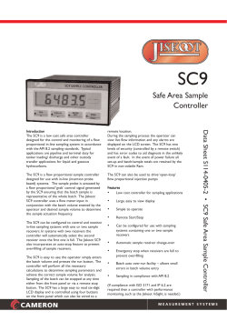


© Copyright 2026