
SF LaserGasTest USERS’s MANUAL 6
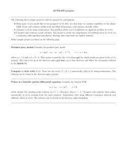
HLS Hypertech Laser Systems GmbH
SF6 LaserGasTest: System & Software User’s Manual
SF6 LaserGasTest
USERS’s
MANUAL
Revision A1.6.2
HLS Hypertech Laser Systems GmbH
Maria-Goeppert-Str. 1; D-23562 L¨
ubeck; Germany
Tel: +49(0)451 1213680 fax: +49(0)451 1213681
[email protected]
http://www.hypertech-lasers.de
HLS Hypertech Laser Systems GmbH
SF6 LaserGasTest: System & Software User’s Manual
ii of 46
LGTManual EN A1.6.2
Date: 06. May 2014,
Revision: A1.6.2
HLS Hypertech Laser Systems GmbH
SF6 LaserGasTest: System & Software User’s Manual
CONTENTS
Contents
Contents
iii
List of Figures
v
List of Tables
v
Revision history
vii
1 Device principles and description
1.1 Application of the device . . . . . . . . . . . .
1.2 Technical parameters . . . . . . . . . . . . . .
1.2.1 Main technical parameters of the LGT
1.2.2 Electrical supply parameters . . . . .
1.2.3 Weight and size parameters . . . . . .
1.3 Detector overview . . . . . . . . . . . . . . .
1.3.1 Inner view . . . . . . . . . . . . . . . .
1.3.2 Outer view . . . . . . . . . . . . . . .
1.3.3 Service items and accessories . . . . .
1.4 Structure and performance of the detector . .
1.4.1 Function principles . . . . . . . . . . .
1.4.2 Structure of detector . . . . . . . . . .
1.4.3 Hand-held unit (HHU) . . . . . . . . .
1.4.4 Detector functional modes . . . . . . .
. . . . .
. . . . .
detector
. . . . .
. . . . .
. . . . .
. . . . .
. . . . .
. . . . .
. . . . .
. . . . .
. . . . .
. . . . .
. . . . .
.
.
.
.
.
.
.
.
.
.
.
.
.
.
.
.
.
.
.
.
.
.
.
.
.
.
.
.
.
.
.
.
.
.
.
.
.
.
.
.
.
.
.
.
.
.
.
.
.
.
.
.
.
.
.
.
.
.
.
.
.
.
.
.
.
.
.
.
.
.
.
.
.
.
.
.
.
.
.
.
.
.
.
.
.
.
.
.
.
.
.
.
.
.
.
.
.
.
.
.
.
.
.
.
.
.
.
.
.
.
.
.
.
.
.
.
.
.
.
.
.
.
.
.
.
.
.
.
.
.
.
.
.
.
.
.
.
.
.
.
.
.
.
.
.
.
.
.
.
.
.
.
.
.
.
.
.
.
.
.
.
.
.
.
.
.
.
.
.
.
.
.
.
.
.
.
.
.
.
.
.
.
9
9
9
9
10
10
11
11
12
12
13
13
13
15
18
2 Detector operation
2.1 Applicational limitations . . . . . . . . . . . . . . . . .
2.2 Preparation of the operation . . . . . . . . . . . . . . .
2.2.1 Unpacking and outer inspection . . . . . . . . .
2.2.2 Charging of the battery . . . . . . . . . . . . .
2.2.3 Switching on the detector . . . . . . . . . . . .
2.2.4 First use . . . . . . . . . . . . . . . . . . . . . .
2.2.5 Switching off the detector . . . . . . . . . . . .
2.2.6 Checking the working condition of the detector
2.3 Use of the detector . . . . . . . . . . . . . . . . . . . .
2.3.1 General instructions . . . . . . . . . . . . . . .
2.3.2 Description of the measurement methods . . .
2.4 Detector connection to the computer . . . . . . . . . .
2.5 Calibration of the detector . . . . . . . . . . . . . . . .
2.6 Routine in fault conditions . . . . . . . . . . . . . . .
.
.
.
.
.
.
.
.
.
.
.
.
.
.
.
.
.
.
.
.
.
.
.
.
.
.
.
.
.
.
.
.
.
.
.
.
.
.
.
.
.
.
.
.
.
.
.
.
.
.
.
.
.
.
.
.
.
.
.
.
.
.
.
.
.
.
.
.
.
.
.
.
.
.
.
.
.
.
.
.
.
.
.
.
.
.
.
.
.
.
.
.
.
.
.
.
.
.
.
.
.
.
.
.
.
.
.
.
.
.
.
.
.
.
.
.
.
.
.
.
.
.
.
.
.
.
.
.
.
.
.
.
.
.
.
.
.
.
.
.
.
.
.
.
.
.
.
.
.
.
.
.
.
.
.
.
.
.
.
.
.
.
.
.
.
.
.
.
.
.
.
.
.
.
.
.
.
.
.
.
.
.
21
21
21
21
22
22
23
24
25
26
26
26
27
27
27
A Display symbols and device symbols
Date: 06. May 2014,
Revision: A1.6.2
LGTManual EN A1.6.2
29
iii of 46
B Menu structure
33
C Declaration of conformity
45
HLS Hypertech Laser Systems GmbH
SF6 LaserGasTest: System & Software User’s Manual
List of Figures
List of Figures
1.1
1.2
1.3
1.4
1.5
Overview of the detector . . . . . . . . . . . . . . .
The SF6 LaserGasTest detector in transport mode.
Compartment for accessories. . . . . . . . . . . . .
Schematic structure of the SF6 LaserGasTest. . . .
Outer view of the HHU unit of SF6 LaserGasTest.
2.1
HHU monitor during measurement in NORMAL mode. . . . . . . . . . . . . . . 23
B.1
B.2
B.3
B.4
B.5
B.6
B.7
B.8
B.9
B.10
Light and Sound menu of the device. . . . . .
Timer Menu of the device. . . . . . . . . . .
Mode and Service Menu of the device. . . . .
Record Menu of the device. . . . . . . . . . .
Format Menu of the device. . . . . . . . . . .
Units Menu of the device. . . . . . . . . . . .
Differential Mode of the device. . . . . . . . .
Monitor Mode of the device. . . . . . . . . .
Monitor Mode continued of the device. . . .
Alarm and Peak hold Function of the device.
.
.
.
.
.
.
.
.
.
.
.
.
.
.
.
.
.
.
.
.
.
.
.
.
.
.
.
.
.
.
.
.
.
.
.
.
.
.
.
.
.
.
.
.
.
.
.
.
.
.
.
.
.
.
.
.
.
.
.
.
.
.
.
.
.
.
.
.
.
.
.
.
.
.
.
.
.
.
.
.
.
.
.
.
.
.
.
.
.
.
.
.
.
.
.
.
.
.
.
.
.
.
.
.
.
.
.
.
.
.
.
.
.
.
.
.
.
.
.
.
.
.
.
.
.
.
.
.
.
.
.
.
.
.
.
.
.
.
.
.
.
.
.
.
.
11
12
13
14
16
.
.
.
.
.
.
.
.
.
.
.
.
.
.
.
.
.
.
.
.
.
.
.
.
.
.
.
.
.
.
.
.
.
.
.
.
.
.
.
.
.
.
.
.
.
.
.
.
.
.
.
.
.
.
.
.
.
.
.
.
.
.
.
.
.
.
.
.
.
.
.
.
.
.
.
.
.
.
.
.
.
.
.
.
.
.
.
.
.
.
.
.
.
.
.
.
.
.
.
.
.
.
.
.
.
.
.
.
.
.
.
.
.
.
.
.
.
.
.
.
.
.
.
.
.
.
.
.
.
.
.
.
.
.
.
.
.
.
.
.
34
35
36
37
38
39
40
41
42
43
Table of technical parameters of the SF6 LaserGasTest . .
List of electrical parameters . . . . . . . . . . . . . . . . .
List of size and weight parameters . . . . . . . . . . . . .
Packing list of SF6 LaserGasTest detector . . . . . . . . .
Port marking . . . . . . . . . . . . . . . . . . . . . . . . .
The assignment of indicators. . . . . . . . . . . . . . . . .
Assignment and functional purpose of the control buttons.
.
.
.
.
.
.
.
.
.
.
.
.
.
.
.
.
.
.
.
.
.
.
.
.
.
.
.
.
.
.
.
.
.
.
.
.
.
.
.
.
.
.
.
.
.
.
.
.
.
.
.
.
.
.
.
.
.
.
.
.
.
.
.
.
.
.
.
.
.
.
.
.
.
.
.
.
.
.
.
.
.
.
.
.
.
.
.
.
.
.
.
10
10
10
11
12
15
18
List of Tables
1.1
1.2
1.3
1.4
1.5
1.6
1.7
A.1 Symbols on LCD screen . . . . . . . . . . . . . . . . . . . . . . . . . . . . . . . . 31
Date: 06. May 2014,
Revision: A1.6.2
LGTManual EN A1.6.2
v of 46
List of Tables
vi of 46
HLS Hypertech Laser Systems GmbH
SF6 LaserGasTest: System & Software User’s Manual
LGTManual EN A1.6.2
Date: 06. May 2014,
Revision: A1.6.2
HLS Hypertech Laser Systems GmbH
SF6 LaserGasTest: System & Software User’s Manual
Revision history
Revision
Beta 0.1
A 1.0
A 1.1
A
A
A
A
A
A
A
1.2
1.3
1.4
1.5
1.6
1.6.1
1.6.2
Changes
initial version
first final version
removed ref. to radar, minor formatting, updated device symbols
updated declaration of conformity
updated menu and text
updated text
updated to FW version above v20140317
corrected layout
fix typos
update work cond. check
Date: 06. May 2014,
Revision: A1.6.2
LGTManual EN A1.6.2
Revision date
08. October 2012
12. October 2012
19. March 2013
26.
03.
13.
19.
26.
07.
05.
July 2013
February 2014
March 2014
March 2014
March 2014
April 2014
May 2014
vii of 46
HLS Hypertech Laser Systems GmbH
SF6 LaserGasTest: System & Software User’s Manual
viii of 46
LGTManual EN A1.6.2
Date: 06. May 2014,
Revision: A1.6.2
HLS Hypertech Laser Systems GmbH
SF6 LaserGasTest: System & Software User’s Manual
Chapter 1
Device principles and description
1.1
Application of the device
1. The device is intended for technological leak-tightness control of the equipment and
parts containing sulfur hexafluoride SF6 for precise leakage localization. This device
is intended for control of the equipment condition in different areas:
• on the power facilities (high-voltage gas-insulated measuring transformers of current and voltage, switchgears, high-voltage circuit breakers, SF6 isolated highvoltage cables)
• building industry (leakage testing of the SF6 -filled double-glazed windows)
• control of the fire extinguishing systems, where SF6 is used as an extinguishing
substance
2. SF6 LaserGasTest environmental conditions:
• Temperature +40 ◦C . . . =40 ◦C
• Relative humidity not more 98 % at the temperature 25 ◦C
• Air pressure 8.4 × 10⁴ Pa . . . 10.67 × 10⁴ Pa (630 mmHg . . . 800 mmHg)
3. On the dust and humidity protection, the detector in transport mode meets the requirement of IP 65 protection class. In the transport mode, the detector is dust
protected as well as protected against water ingress
1.2
1.2.1
Technical parameters
Main technical parameters of the SF6 LaserGasTest detector
The main technical parameters of the laser and sensor, as well as the units sensitivity are
given in Table 1.1.
Date: 06. May 2014,
Revision: A1.6.2
LGTManual EN A1.6.2
9 of 46
1.2. TECHNICAL PARAMETERS
HLS Hypertech Laser Systems GmbH
SF6 LaserGasTest: System & Software User’s Manual
Aim substance
Detector type
Radiation source
Laser wavelength
Average laser power not over
Cold start time not over
Response time not over
Probe air flow
SF6 Sensitivity limit not more
Maximum concentration of SF6
Measurement precision not below
SF6 gas
resonance opto-acoustic
CO2 laser
10.6 µm
0.5 W
2 min
2s
(0.55 ± 0.05) l/min
0.01 ppm
5000 ppm
10 % of measured value unit 1000 ppm
Table 1.1: Table of technical parameters of the SF6 LaserGasTest
1.2.2
Electrical supply parameters
The electrical supply is performed through the built-in rechargeable battery or 110 V/220 V/
50 Hz AC mains. Built-in rechargeable battery has a SMART BATTERY control and
diagnostics system. This supports the balance of the battery cells, compensates the changes
in the battery parameters and protected the cells on the current overload, overcharge and
deep discharge.
Built-in battery type
Battery cell connection
Nominal battery capacity
Nominal battery power
Continuous operation time not less than
Charging time no more than
Mains voltage
Mains frequency
Maximum consuming AC power no more
than
Li-Ion
4s1p
4.8 A h
72 W h
10 h
2.5 h
90 V . . . 132 V;187 V . . . 264 V
47 Hz . . . 63 Hz
90 W
Table 1.2: List of electrical parameters
1.2.3
Weight and size parameters
Detector in transport mode
Hand-held unit
Length of the flexible intake
Length of the telescopic intake
Hand-held unit connection cable length
Weight of the parts and complete detector:
Detector weight in transport mode not over
Hand-held tool weight not over
335 x 280 x 135 mm
203 x 56 x 63 mm
(200 ± 5) mm
220 mm . . . 980 mm
(1520 ± 50) mm
6.0 kg
0.22 kg
Table 1.3: List of size and weight parameters
10 of 46
LGTManual EN A1.6.2
Date: 06. May 2014,
Revision: A1.6.2
HLS Hypertech Laser Systems GmbH
SF6 LaserGasTest: System & Software User’s Manual
1.3
1.3.1
1.3. DETECTOR OVERVIEW
Detector overview
Inner view
The view of the detector with open cover of the main unit and described content is presented
in Figure 1.1
6
5
1.
2.
3.
4.
5.
6.
7
8
9
10
11
4
12
7.
13
3
14
15
2
8.
9.
1
10.
18 17 16
Figure 1.1: Overview of
Left port cap
Flexible tip
Power button
Telescopic tip
Locks
Compartment
for power cable
Compartment
for USB A-B cable
Upper cover
Labeling place
inside the detector
Compartment
for
technical
the detector
11.
12.
13.
14.
15.
16.
17.
18.
maintance accessories,
for
details see Figure 1.3
Display
Hand-held unit
labeling place
Hand-held unit
(HHU)
Connection cable
Detector case
Plug for connection cable
Headphones
jack
Outflow valve
The packing list of the SF6 LaserGasTest detector is given in Table 1.4.
The main unit of the detector is a tight shock-proof case which functions as a container
for the detector where the main parts are located, as well as a case for transportation. This
solution allows simple transportation to the work site by means of handle or with help of
shoulder belt.
There are plug ports located on the sides of the case (Table 1.5), which are inclosed
with rubber caps. This plugs are marked in respect to the port: hand-held unit (HHU),
headphones, power net cable, USB A-B cable, outflow valve.
Main unit
Hand-held tool
Flexible tip
Telescopic tip
Connection cable
Headphones
Net cable
USB A-B cable
Tweezers
Replacable filter
Shoulder belt for detector transportation
USB Stick with software
User Manual
1
1
1
1
1
1
1
1
1
4
1
1
1
pc.
pc.
pc.
pc.
pc.
pc.
pc.
pc.
pc.
pc.
pc.
pc.
pc.
Table 1.4: Packing list of SF6 LaserGasTest detector
Date: 06. May 2014,
Revision: A1.6.2
LGTManual EN A1.6.2
11 of 46
HLS Hypertech Laser Systems GmbH
SF6 LaserGasTest: System & Software User’s Manual
1.3. DETECTOR OVERVIEW
exhaust valve
AIR OUT
HEADPHONE CONNECTION
plug for HHU
HHU
220 V
headphone plug
USB CONNECTION
USB-B plug
POWER NET PLUG
plug for power connector
cord
Table 1.5: Port marking
In the transport mode the accessories, HHU, tip and connection cable are located in
respective compartments inside the case.
1.3.2
Outer view
The detector in transport mode is shown in Figure 1.2.
3
4
1. Detector case
2
2. Locks
3. Device handle
4. Shoulder belt
5. Labeling place of the main case
1
5
Figure 1.2: The SF6 LaserGasTest detector in transport mode.
1.3.3
Service items and accessories
The following items are included in the delivery with each detector:
• tweezers
• exchangable filters
12 of 46
LGTManual EN A1.6.2
Date: 06. May 2014,
Revision: A1.6.2
HLS Hypertech Laser Systems GmbH
SF6 LaserGasTest: System & Software User’s Manual
1.4. STRUCT. OF DETECTOR
Accessories for the service are located in special compartment of the main unit (Figure 1.1). The USB flash drive with software is also located there.
The view of the opened service and acessories compartment is presented in Figure 1.3.
ATTENTION!
Please do not unscrew service compartment. It is intended to provide service only by
the manufacturer.
1. Power button
2. Indicator
3. Service compartment cover
1
2
4. Cover for the input filter
3
4
5. Cover for replacement filter storage
5
6. tweezers
6
7
7. magnetic latch for accessories cover
Figure 1.3: Compartment for accessories.
1.4
1.4.1
Structure and performance of the detector
Function principles
To determine the air-tightness of the controlled object and to localize the leakages, the
following routine should be followed. The controlled object is filled with SF6 gas or gas
mixture doped with SF6 .
The pressure inside the controlled object should exceed the atmospheric pressure by
0.5 atm . . . 5 atm. In case of leakages, the air around the leakage localization will have
increased concentration of SF6 molecules.
After pulling the trigger on the HHU handle, the air pump starts working and the air
sample is pumped inside the detector through a hand-held tool tip (flexible or telescopic).
This air sample is pumped through the pneumatic path of the detector and analyzed. The
laser-acoustic spectroscopy method is used for the determination of the SF6 molecules concentration. The acoustic waves are emitted in the gas probe due to absorption of the laser
radiation by SF6 molecules.
1.4.2
Structure of detector
The general scheme of the detector is presented in Figure 1.4. The intake (1) is connected
via adapter (2.1). to the HHU (2). The HHU (2) is connected to the main block (8) via the
combined pneumo-electric cable (4). The air sample is pumped through the intake (1), HHU
(2) and a cable (4) into the main unit pneumatic path. Inside the main unit, the air passes
the entrance filter (8.3) and then is pumped to the optical-accoustic detector (OAD) (8.10).
After the OAD, the air probe continues to the acoustic muffler (8.9) which suppresses the
air flow pulses appearing due to the function of the air pump (8.2).
Date: 06. May 2014,
Revision: A1.6.2
LGTManual EN A1.6.2
13 of 46
HLS Hypertech Laser Systems GmbH
SF6 LaserGasTest: System & Software User’s Manual
1.4. STRUCT. OF DETECTOR
2
1
Probe
intake
8
Hand-Held Tool
Main Block
2.1
Dust filter
8.9
8.2
8.1
2.2
Silencer
Pump
8.3
Display
4
2.3
8.10
Dust filter
Opticacoustic
detector
8.4
PCB
LASER
2.5
2.4
LED headlight
8.5
8.11
LASER Power Source
Keys
8.6
Indication module
3
Headphones
Main Board
PC (USB)
5
8.7
Battery
8.8
~220 VAC
6
AC/DC Power source
Figure 1.4: Schematic structure of the SF6 LaserGasTest.
Entrance air filter (8.3) prevents solid and liquid aerosol particles on the optical elements
in the pneumatic path of the detector. The exit protection valve (8.1) is located at the end
of the pneumatic path.
The determination of the SF6 concentration in the air sample is performed in the OAD
(8.10). The laser radiation (8.4) excites an acoustic wave which is detected by OAD microphones (8.10). The electric signal from the microphones is transmitted for further processing
to the main board (8.11). The main board (8.11) processes the signal of the OAD microphones and controls the indicator panel (8.6) that indicates the main parameters and modes
of the device function. It also controls air pump (8.2) and performs the control signals of
the laser power supply (8.5).
The indicator assignment is presented in the Table 1.6.
The power supply system of the detector consists of rechargeable battery (8.7) and AC
power supply (8.8). Battery (8.7) supports the autonomous function of the detector. AC
power supply (8.8) supports the function from the mains and recharge of the battery (8.7).
To power the device from mains, an AC cable with plug (6) is supplied with detector.
The device can be controlled via HHU (2). The control buttons (2.5) are located on the
HHU. They are connected with the control board of the HHU (2.3). Indicator (2.2) displays
the measured values and working modes of the detector. LED illumination (2.4) is located
on the operating side of the HHU. It illuminates the HHU intake and improves the process
of the leakage localization in dark places. Two HHU exchangeable intakes (2.1) (flexible and
telescopic) are contained in the delivery to improve the gas sample collecting process.
The detector can be connected to the computer via USB cable (5). A full control of the
detector functions is possible by means of an external computer. Also the read-out of the
measured values is possible. If needed, headphones (3) can be connected to the detector in
loud environment.
14 of 46
LGTManual EN A1.6.2
Date: 06. May 2014,
Revision: A1.6.2
HLS Hypertech Laser Systems GmbH
SF6 LaserGasTest: System & Software User’s Manual
1.4. STRUCT. OF DETECTOR
POWER
This sign is GREEN when the system is ON
EXTERNAL
This sign is GREEN when the system is connected to the main
BATTERY
This sign is GREEN when the battery is
charged. This sign is RED when battery is
discharged.
CHARGE
This sign is ORANGE when battery is charging
REMOTE
This sign is GREEN when active connection
with external PC
RECORD
This sign is RED when recording data to the
internal memory
This sign is RED when:
• Lost contact with HHU
• Error of the internal charge control
ERROR
• Error of the internal memory
• Measuring system fault
STAND BY
Display in standby (energy saving mode, no
measurements are carried out)
Table 1.6: The assignment of indicators.
1.4.3
Hand-held unit (HHU)
HHU is designed for input and output of all detector functions. The Outer view is presented
in Figure 1.5.
The Hand-held unit consists of control keys (1,2,4,5) and an OLED screen (3) for HHU
monitor. The LED illumination (7) can be switched on according to the operator needs to
improve work efficiency in limited illumination conditions. On the input port (6) the flexible
or telescopic probe can be connected. Via the connector plug (9) and an electropneumatic
cable the connection to the main unit is established.
The control of the detector via HHU is performed by pressing control buttons UP,
DOWN, ENTER, ESCAPE and START.
Assignment and functional purpose of the control buttons is presented in Table 1.7.
Date: 06. May 2014,
Revision: A1.6.2
LGTManual EN A1.6.2
15 of 46
HLS Hypertech Laser Systems GmbH
SF6 LaserGasTest: System & Software User’s Manual
1.4. STRUCT. OF DETECTOR
3
2
1
4
6
7
5
8
9
1. DOWN control button
6. connector for tip
2. ESCAPE control button
7. LED illumination
3. OLED Display
8. START control button
4. ENTER control button
9. combined plug for connection cable to
5. UP control button
main unit
Figure 1.5: Outer view of the HHU unit of SF6 LaserGasTest.
Sign
Assignment Functional purpose
• Transition to the selected line submenu from one of the main graphic
screen menus
• setting the value for the selected
parameter in the line submenu
without selection of the additional
parameters
ENTER
16 of 46
Cursor view
• Rectangular frame
becomes rectangular
completely filled
• Filled rectangular
becomes rectangular
frame
• transition in one of main graphic
menus
• transition in the selection mode to
choose one of the text or digital values in the element of the line submenu
• Square
brackets
appear in the filled
rectangular
• exit from mode of the selection of
text or digital values in the line
submenu with saving the entered
parameters
• Square brackets disappear in the filled
rectangular
LGTManual EN A1.6.2
Date: 06. May 2014,
Revision: A1.6.2
HLS Hypertech Laser Systems GmbH
SF6 LaserGasTest: System & Software User’s Manual
Sign
1.4. STRUCT. OF DETECTOR
Assignment Functional purpose
• return from line submenu to one of
the main screen graphic menus
ESCAPE
UP
• exit from the selected value of the
line submenu and saving of the previously set value without changes
• The square brackets disappear in the
filled rectangular
• Rectangular frame
• cursor movement in the upper direction while being in a text submenu
• Filled rectangular
• selection of the digital or text parameters to set the values in the
line submenu
• Square brackets
• cursor movement one line down
while being in a text submenu
• selection of the digital or text parameters to set the values in the
line submenu
Date: 06. May 2014,
Revision: A1.6.2
• Filled rectangular
becomes rectangular
frame
• cursor movement on the previous
submenu icon while being in one of
the main graphic menus
• cursor movement on the following
submenu icon while being in one of
the main graphic menus
DOWN
Cursor view
LGTManual EN A1.6.2
• Rectangular frame
• Filled rectangular
• Square brackets
17 of 46
HLS Hypertech Laser Systems GmbH
SF6 LaserGasTest: System & Software User’s Manual
1.4. STRUCT. OF DETECTOR
Sign
Assignment Functional purpose
Cursor view
• in the main measurement mode;
start/stop of the measurement
• in the differential measurement
mode, if no basic value defined
start/stop of the basic line concentration measurement
START
• in differential measurement mode
if the basic line value is defined
start/stop of the measurement
• in the monitoring mode start of the
measurement, if the detector was in
stand by mode
• in the monitoring mode recalls the
window for the end of measurement
confirmation if the measurement is
running
NOTE: In the table the graphic pictogram of the main trigger is presented under
the START trigger HHU.
Table 1.7: Assignment and functional purpose of the control buttons.
1.4.4
Detector functional modes
• main measurement mode (Normal);
• differential measurement mode (Differential)
• monitoring mode (Monitor)
Normal mode is intended for the SF6 concentration measurement (ppm/ppb) and the
leakage intensity. During the concentration definition, a precision is not worse than 10 %
at air temperature (25 ± 2) ◦C. In Normal mode additional functions are available in the
submenu Function
• Peak hold saves and indicates the maximum value detected during current measurement;
• Alarm level The threshold level on the SF6 concentration can be set. If the threshold
had been exceeded, an alarm signal will be released. The acoustic alarm can be set in
the submenu EXTRA SETTINGS.
Differential mode is intended for measurement of the SF6 concentration with subtraction of the background concentration.
Monitor mode is designed for periodical measurements in defined times and saving of
the measurement results. The detector in this mode works without operator.
The measurement procedure can be provided with audible signal support with beeping
frequency proportional to the gas concentration. The sound signal can be provided trough
a built-in speaker or through headphones (for example in case of noisy environment).
18 of 46
LGTManual EN A1.6.2
Date: 06. May 2014,
Revision: A1.6.2
HLS Hypertech Laser Systems GmbH
SF6 LaserGasTest: System & Software User’s Manual
1.4. STRUCT. OF DETECTOR
During operation in areas with low levels of light, the HHU LED illumination can be
used to improve the screen visibility.
For the correct leak intensity measurement it is important to ensure that all leaking SF6
gas enters the HHU tip. In this case the precision of the measurement is not given.
The information regarding the measured SF6 concentration is indicated on the HHU
monitor in ppm (Mio-1 ) or ppb (0.001 Mio-1 ). During the leakage intensity measurement,
the resulting value can be indicated in grams per year (g/year), grams per month (g/month),
grams per week (g/week) or grams per day (g/day).
Date: 06. May 2014,
Revision: A1.6.2
LGTManual EN A1.6.2
19 of 46
1.4. STRUCT. OF DETECTOR
20 of 46
HLS Hypertech Laser Systems GmbH
SF6 LaserGasTest: System & Software User’s Manual
LGTManual EN A1.6.2
Date: 06. May 2014,
Revision: A1.6.2
HLS Hypertech Laser Systems GmbH
SF6 LaserGasTest: System & Software User’s Manual
Chapter 2
Detector operation
2.1
Applicational limitations
It is NOT ALLOWED to use the detector in rooms with following danger factors:
• vapours of chemicaly active VOC’s in concentrations over allowed limitations
• explosive atmospheres
ATTENTION!
During work in areas where the danger of high SF6 concentration is present one has
to take the important safety measures. If measuring the SF6 concentration in a room, the
measurement must be performed on the height not over 15 cm from the floor.
PLEASE DO NOT take measurements on devices which are under voltage using standard probe tips. The high voltage equipment must be switched off and grounded according
to the working routines and Standard Operating Procedures. The special dielectric probe
tip is required to take measurements of high voltage equipment during operation.
PLEASE DO NOT immerse the probe tip in liquids and to allow liquids to enter the
pneumatic path of the detector. In this case the detector will be damaged.
PLEASE DO NOT use the detector if it’s case, plugs, cables or HHU are damaged.
ATTENTION!
If working at the sites please do not with dust contaminants it is important to exchange
the air filter if it becomes contaminated, at least as often, as subscribed by present manual.
ATTENTION!
To ensure the long battery life it is important to charge it regularly. The battery charge
level is controlled by the BATTERY indicator. Battery failure is not covered by the
manufacturer warranty.
2.2
2.2.1
Preparation for operation
Unpacking and outer inspection
Pull out the detector case from the package carefully. Place it on a plain clean surface and
provide outer inspection. One has to check:
• delivery completeness
• absence of visible mechanical damage
• condition of plugs and cables
Date: 06. May 2014,
Revision: A1.6.2
LGTManual EN A1.6.2
21 of 46
2.2. PREP. OF OPERATION
HLS Hypertech Laser Systems GmbH
SF6 LaserGasTest: System & Software User’s Manual
• presence of sealing and marking
Before operation starts, the manual has to be read thoroughly and attentively. The operator has to familiarise himself with the position and designation
of the plugs and controls of the detector.
2.2.2
Charging of the battery
After outer inspection is complete, the battery must be charged completely before the detector is switched on.
For charging:
• switch the power net cable to the plug marked with 220 V sign
• plug the power net cable tip to the external power net socket. After that the indicators
POWER, EXTERNAL, BATTERY, CHARGE, ERROR will light on;
• when the charge level reaches the nominal value, CHARGE indicator will go off and
the BATTERY indicator will become green.
Charging time depends on the battery level, but is no longer than 2.5 hours.
2.2.3
Switching on the detector
General indications
Transport mode of the detector is presented in Figure 1.2.
The control of the detector operation is performed via the HHU. It is also possible to
connect the detector to a PC. There are two working modes possible in this case:
• PC provides the control of working modes and saving of the measurement results.
• PC works as an observer - detector works independently from the PC, and the measurement results are shown on the PC monitor
Turning the detector from transport mode to working mode:
• place the detector on plain clean surface
• open the locks 5 of the case 15 (according to Figure 1.1)
• open the cover 8 of the case and leave it opened
• remove the cap 1 of the main unit
• connect the tip 2 to the HHU 13
• connect the HHU 13 to the main plug 16 on the case with the connection cable 14,
take care to get the correct orientation of the cable, indicated by a red spot
• press the power button 3 of the detector; indicators POWER and BATTERY located
at the indicator board 11 will start lighting
• close the upper cover 8 of the detector
22 of 46
LGTManual EN A1.6.2
Date: 06. May 2014,
Revision: A1.6.2
HLS Hypertech Laser Systems GmbH
SF6 LaserGasTest: System & Software User’s Manual
2.2. PREP. OF OPERATION
Figure 2.1: HHU monitor during measurement in NORMAL mode.
After switching on the detector, the HHU monitor will show the logo of the HLS followed
by a self diagnostic routine.. After finishing this routine the detector goes in standby mode.
To start the measurements in NORMAL mode, the START trigger of the HHU must be
pressed. Second press of the START trigger will stop the measurement. The view of the
HHU monitor during the NORMAL measurement mode is presented in Figure 2.1.
If the battery has to be charged and/or the detector has to work from the AC power
supply 110 V/220 V, the detector must be connected to the ∼220 V mains supply.
The battery status can be checked inside the main unit when the cover is open, by
controlling the indicators on panel 10:
• in case if the detector is working from ∼220 V supply and the battery is fully charged,
the indicators POWER and EXTERNAL will be on and the indicator BATTERY will
light green
• if the detector is working from ∼220 V and the battery is charging, the indicators
POWER, EXTERNAL and CHARGE will light
• if the detector works from the battery, indicators POWER and BATTERY will light;
color of the BATTERY indicator depends on the charge of the battery: at a working
charge level green, at low charge level red.
ATTENTION!
To avoid damage of the LEMO plug contacts, one has to pay special attention during
the connection of the cable to the HHU and main device. Please follow the routine below:
• make sure that red marks on the cable plug and on the socket of the main device (or
cable plug and the HHU) are aligned
• holding on the corrugated part, connect the plug without applying extra force; keep
gently pressing until the plug lock clicks
2.2.4
First use
At first use follow the steps mentioned in 2.2.1 – 2.2.3 . After long periods of storage or
at first use, some chemicals may reside in the detector cell and influence the measurement
results. In this case please let the detector run in NORMAL mode until the values settle
(up to 30 minutes).
Date: 06. May 2014,
Revision: A1.6.2
LGTManual EN A1.6.2
23 of 46
2.2. PREP. OF OPERATION
HLS Hypertech Laser Systems GmbH
SF6 LaserGasTest: System & Software User’s Manual
IMPORTANT!
To improve the measurement precision in case of low SF6 concentrations (<100 ppm)
during the long-term measurements it is recommended to restart the detector by double
pressing the Start trigger.
ATTENTION!
In case of long-term measurements of high SF6 concentrations (>100 ppm), gas particles
can be absorbed by the pneumatic tract of the detector. It is recommended to place the
detector in the area with clean air and keep it running in the measurement mode witin a
time equal to the measurement time of the high SF6 concentrations. This procedure ensures
cleaning of the pneumatic tract from the gas rests.
2.2.5
Switching off the detector
General instructions
To ensure comfortable work with the detector, the following options of partial and full
switching off are implemented:
• waiting mode Stand By
• mode with the HHU display switched off: Display OFF
• complete turn off using the main switch
“Stand by” mode
Stand By mode is designed for quick switching of the working detector in a low energy
consumption mode. This mode is useful to provide series of measurements separated with
small periods of time instead of complete switching off and turning the detector in the
transport mode.
This mode can be chosen in EXTRA SETTINGS menu.
Leaving the Stand By mode is done by pressing ENTER button. Any other buttons and
combinations are blocked and do not lead to leaving of the Stand By mode. Choosing Stand
By mode is possible only if there is no measurement running. Indication of Stand By mode
is provided on the indicator panel of the main unit.
“Display OFF” mode with switched off HHU display
This mode is designed to switch HHU screen off rapidly. This mode is designed to be used
during the measurements (for example in monitoring mode). Use of Display OFF mode
extends the operation from the battery operation time.
Selection of this mode is through the menu of additional settings Extra Settings. Exit
from this mode is done by pressing any of the detector buttons except START button.
Switching off the detector in Stand by mode hot start
• Stop the measurement pressing the Start trigger.
• Put the detector case on a clean plain surface
• open the locks 5 of the detector case 15 (Figure 1.1)
• open the case cover 8 of the main detector block
• press the power button 3 in the off position
• close the upper cover 8 of the detector case
24 of 46
LGTManual EN A1.6.2
Date: 06. May 2014,
Revision: A1.6.2
HLS Hypertech Laser Systems GmbH
SF6 LaserGasTest: System & Software User’s Manual
2.2. PREP. OF OPERATION
Routine to turn the detector from the work position into the transport position
• Stop the measurement by pressing START trigger
• Place the detector on clean plain surface
• Open the locks 5 of the case 15 (Figure 1.1)
• Open the case cover 8 of the main detector block
• Press the power button 3 in the off position
• Unscrew the tip 2 from the HHU 13
• Unplug the connection cable 14 from the main unit
• Place the parts of the device in the respecive compartments of the case
• Close the plug 1
• Close the upper part 8 of the case 15.
ATTENTION!
To prevent the damage to the connection cable during the unplugging procedure, follow
the routine as described below:
• smoothly pull the cable LEMO plug out, holding it on the corrugated part of the plug;
do not rotate the plug;
• disconnect the plug without using extra force
PLEASE DO NOT disconnect the cable from the main unit or HHU with any other
methods.
2.2.6
Checking the working condition of the detector
The working condition of the detector can be checked by applying a gas mixture with known
SF6 concentration (check the mixture calibration certificate and mixture validity date!):
1. prepare or order test gas mixture with known volumetric content of SF6 (according to
EN 6144 or EN 6145)
2. plug the container with the gas mixture to the detector HHU tip
3. set the NORMAL measurement mode
4. start the concentration measurement by pressing the START trigger
5. after 5 s . . . 10 s read the measurement results
6. the measured concentration must fit the initial concentration within 10 %
Date: 06. May 2014,
Revision: A1.6.2
LGTManual EN A1.6.2
25 of 46
HLS Hypertech Laser Systems GmbH
SF6 LaserGasTest: System & Software User’s Manual
2.3. USE OF THE DETECTOR
2.3
Use of the detector
2.3.1
General instructions
To start work with the detector one has to follow the routine as described in chapter 2.2.3
above. Parameters and working modes can be set with the navigation buttons browsing the
respective menus if needed.
The graphic menu of the HHU is designed to set the parameters and working modes of
the detector. Optimal parameters and working modes depend on the measurement goals
and parameters of the tested objects. The map of the navigation menu is presented in
appendix B. Navigation through the menu is done by the navigation buttons according to
1.7.
It is possible to use the detector without the handpiece, but in this case, the control and
measurement results storage has to be provided through the PC.
2.3.2
Description of the measurement methods
The detector is used for the detection of the SF6 leakages from the gas filled
devices according to IEC 600682-17 providing measurements at the
atmospheric pressure.
• tester
• collection at the atmospheric pressure
During the leakage detection with the detector test object has to be filled with SF6
or the air-gas mixture with at least 1 % of SF6 at an excessive pressure of 1 atm . . . 6 atm
according to the limitations of the tested object. Leakage search is performed by moving
the HHU intake along the controlled areas of the tested object. Due to the low mobility
of SF6 molecules, the concentration increase is observed at the leakage location. When the
HHU tip approaches the leakage location, the air with SF6 molecules is pumped inside the
pneumatic path of the detector. Localization succeeds on the maximum concentration of
the SF6 as shown on the display or repeated by maximal frequency of the sound signals.
For the leakage detection by means of the sample collection at the atmospheric pressure
the controlled object is filled with the SF6 air-gas mixture with at least 1 % of SF6 . The
object is filled with 1 atm . . . 6 atm excessive pressure according to the technical parameters
of the object. The tested object is placed in a bag, or a chamber filled with air. An air fan
is placed inside the chamber to mix the air with SF6 gas, that comes out from the tested
object in case of leakage.
The HHU intake is inserted into the bag or chamber. The concentration of the SF6 gas
will increase proportionally to the time of the test object observation in the chamber.
The density of the SF6 gas is d=6.139 g/l at 20 ◦C. So the volume concentration of 1 ppm
is equal to concentration of 6.139 µg/l.
Integrated leakage of SF6 from the tested object is defined by the equation 2.1:
M = 0.0538 × ∆C × (VC − VO − Vf )/∆T
(2.1)
where M is an integrated leakage of the SF6 gas in gramms/year, ∆C SF6 concentration
increase in ppm, VC internal volume of the chamber in liters, VO outer volume of the tested
object in liters, Vf outer volume of the fan in liter, ∆T is the time between the measurements
in hours.
To transfer the volume concentration, measured by the detector, in ppm units (Mio-1 )
into the concentration, measured in g/l, the equation 2.2 is used:
∆C(g/l) = ∆C(ppm) × 6.139 × 10⁻⁶
26 of 46
LGTManual EN A1.6.2
(2.2)
Date: 06. May 2014,
Revision: A1.6.2
HLS Hypertech Laser Systems GmbH
2.4. CONN. TO THE COMPUTER
SF6 LaserGasTest: System & Software User’s Manual
If gas insulated transformers have to be checked with this approach, follow the routine,
as described in the standard.
2.4
Detector connection to the computer
The detector has a USB port and can be connected to PC with standard USB A-B cable
which is included in each delivery.
To operate the detector via PC the SF6 LaserGasTest software must be installed. This
software is delivered with each detector.
2.5
Calibration of the detector
The detector must be calibrated every 12 months according to the service manual. The
calibration must be provided by the manufacturer, or authorized dealers.
2.6
Routine in fault conditions
If any precursors of the dangerous situation occur during the detector usage, such as:
• smell of the smoke
• any evidence of burning or sparkling
the detector must be immediately switched off and disconnected from the power net.
The detector could be switched on again only after the source of the danger is located and
eliminated.
Date: 06. May 2014,
Revision: A1.6.2
LGTManual EN A1.6.2
27 of 46
2.6. ROUTINE IN FAULT COND.
28 of 46
HLS Hypertech Laser Systems GmbH
SF6 LaserGasTest: System & Software User’s Manual
LGTManual EN A1.6.2
Date: 06. May 2014,
Revision: A1.6.2
HLS Hypertech Laser Systems GmbH
SF6 LaserGasTest: System & Software User’s Manual
Appendix A
Display symbols and device symbols
Graphical indicator
Assignment
Explanation
fully charged battery
60 % charged battery
critical battery discharge
Protocol
connection
error
no battery installed
Charge indicator of built-in
battery
Stand by
Display OFF
Entering
the
menu of extra
settings / Display
current
values of the
extra
settings
menu
Date: 06. May 2014,
Revision: A1.6.2
LGTManual EN A1.6.2
blinking battery icon
- deferred battery
charge (possible reasons:
low battery
temperature, ending of
period of time charge)
transition to Stand by
switch off the HHU display
LED illumination off
LED illumination on
sound disabled
sound on the HHU
sound on the main
main unit (via attached headphones)
29 of 46
HLS Hypertech Laser Systems GmbH
SF6 LaserGasTest: System & Software User’s Manual
Graphical indicator
Assignment
Explanation
timer is not set
Enter the timer
menu / display
current values of
the timer menu
Enter the menu
measurement
mode / display
of the current
measurement
mode
current value of the
timer if the timer is activated
display HOLD mode
on the main menu
In this mode, HUU’s screen displays the
measured concentrations of SF6 at the time
of the timer 00:00 with measurements
continuing. Continue in NORMAL mode
by pressing the START trigger HHU
triangle shaped icon
indicates the currently
selected mode
enter NORMAL mode
enter
DIFFERENTIAL mode
enter
MONITOR
mode
enter service menu
Enter the menu
Record / display
current values
of the Record
menu
currently measured value or
additional messages
circle indicates recording in progress
measured numerical of the volume concentration of SF6
the measured value exceeds the Threshold
Limit Value (TLV) of 1000 ppm
automatic data format
Enter the menu
for display format of data / indication of the
current reporting format
30 of 46
LGTManual EN A1.6.2
data format without
decimal point
one digit after the decimal point
two digits after the
decimal point
three digits after the
decimal point
Date: 06. May 2014,
Revision: A1.6.2
HLS Hypertech Laser Systems GmbH
SF6 LaserGasTest: System & Software User’s Manual
Graphical indicator
Assignment
Explanation
Possible units for measuring the SF6 concentration:
ppb (10-9 )
ppm (10-6 )
menu for selection of measurement unit /
display current
measurement
unit
automatic switch between ppb and ppm.
When automatic selection is set, font will be
bold.
possible units for measuring the SF6 leakage
rate:
ml/year
ml/second
g/day
Background
concentration of
SF6 indication
and setting
Display
the
time intervals
the
Monitor
modes
g/year
Indication of the background concentration
of SF6 against which the measurements are
in the mode Differential, enter the menu to
determine background concentration
Specified time intervals:
purging
pneumatic
system
(preparing measurement)
data collecting
delay between
surements
mea-
Displays
the
Device audibly indicates exceeding alarm
selected Alarm
level if sound is switched on.
Level
Indication
of
The device is stored and displayed the maximaximum meamum measured concentrations of SF6 in the
sured values of
current series of measurements
the Peak Hold
Table A.1: Symbols on LCD screen
Date: 06. May 2014,
Revision: A1.6.2
LGTManual EN A1.6.2
31 of 46
HLS Hypertech Laser Systems GmbH
SF6 LaserGasTest: System & Software User’s Manual
32 of 46
LGTManual EN A1.6.2
Date: 06. May 2014,
Revision: A1.6.2
HLS Hypertech Laser Systems GmbH
SF6 LaserGasTest: System & Software User’s Manual
Appendix B
Menu structure
Date: 06. May 2014,
Revision: A1.6.2
LGTManual EN A1.6.2
33 of 46
HLS Hypertech Laser Systems GmbH
SF6 LaserGasTest: System & Software User’s Manual
:
REC: 1
:
:
NORMAL
REC: 1
Function
auto
NORMAL
auto
REC: 1
NORMAL
Function
:
NORMAL
REC: 1
594.2
Extra Settings
Sleep Mode
Display OFF
Light: OFF
Sound: OFF
Extra Settings
Sleep Mode
Display OFF
Light: OFF
Sound: OFF
:
NORMAL
REC: 1
auto
Function
:
NORMAL
REC: 1
:
594.2
Function
auto
594.2
Function
Extra Settings
Sleep Mode
Display OFF
Light: OFF
Sound: [OFF]
Sleep Mode
Display OFF
Light: OFF
Sound: [ON]
Extra Settings
Sleep Mode
Display OFF
Light: OFF
Sound: [HP]
Extra Settings
Function
auto
594.2
REC: 1
NORMAL
auto
Extra Settings
auto
Extra Settings
Sleep Mode
Display OFF
Light: [OFF]
Sound: OFF
Extra Settings
Sleep Mode
Display OFF
Light: OFF
Sound: OFF
Sleep Mode
Display OFF
Light: ON
Sound: OFF
Function
:
NORMAL
REC: 1
ppm
>1 TLV
auto
Function
:
NORMAL
REC: 1
ppm
>2 TLV
auto
Function
:
NORMAL
ppm
>2 TLV
REC: 1
auto
Function
Figure B.1: Light and Sound menu of the device.
:
NORMAL
594.2
REC: 1
Function
auto
:
NORMAL
594.2
REC: 1
Function
auto
Date: 06. May 2014,
Revision: A1.6.2
LGTManual EN A1.6.2
34 of 46
:
:
Function
Function
Date: 06. May 2014,
Revision: A1.6.2
Function
auto
594.2
REC: 1
NORMAL
12:21
Function
auto
594.2
REC: 1
NORMAL
19:24
auto
594.2
REC: 1
NORMAL
auto
594.2
REC: 1
NORMAL
LGTManual EN A1.6.2
:
25:00
:
00:00
Start/Pause
Reset
Stop
Set: [2]5:00
Timer
Function
auto
594.2
REC: 1
NORMAL
Function
:
594.2
auto
##.##
OVER RANGE
REC: 1
NORMAL
:
25:00
Start/Pause
Reset
Stop
Set: 25:00
Timer
Start/Pause
Reset
Stop
Set: 14:3[0]
Timer
Function
Function
590.2
OVER RANGE
REC: 1
NORMAL
auto
##.##
594.2
00:00
25:00
auto
##.##
OVER RANGE
REC: 1
NORMAL
Figure B.2: Timer Menu of the device.
Start/Pause
Reset
Stop
Set: 25:00
Timer
Start/Pause
Reload
Stop
Set: 25:00
Timer
auto
Start/Pause
Reload
####
###.#
Stop
Set:
##.##
25:00
Format
Timer
Start/Pause
auto
Reload
####
Stop
###.#
Set:
##.##
25:00
#.###
Format
Timer
H
:
Function
auto
594.2
REC: 1
NORMAL
14:30
Function
auto
592.8
REC: 1
NORMAL
HLS Hypertech Laser Systems GmbH
SF6 LaserGasTest: System & Software User’s Manual
35 of 46
HLS Hypertech Laser Systems GmbH
SF6 LaserGasTest: System & Software User’s Manual
:
NORMAL
REC: 1
:
NORMAL
REC: 1
Mode
Normal
Differential
Monitor
Service
:
REFERENCE SET
DIFFERENTIAL
REF:
auto
594.2
auto
594.2
Function
Pump: OFF
Laser: OFF
Self check
Info
Factory Reset
Service
Pump: OFF
Laser: OFF
Self check
Info
Factory Reset
Service
Pump: OFF
Laser: OFF
Self check
Info
Factory Reset
Service
00:15 00:30 00:30:00
auto
REC: 1
MONITOR
:
0.000
auto
No
Yes
FactoryReset
Connection: ok
Laser: ok
Power: ok
Calibration: ok
MB Flash: ok
HHT Flash: ok
Self Check
Normal
Differential
Monitor
Service
Mode
Normal
Differential
Monitor
Service
Mode
Function
:
NORMAL
REC: 1
auto
Function
:
NORMAL
REC: 1
auto
Function
DM
Service
SN: 0010313
ht: v130520
mb: v130514
crc32: 794A46FE
Laser Run Time [s]:
3410
Info
Pump: OFF
Laser: ON
Self check
Info
Factory Reset
Service
Pump: ON
Laser: OFF
Self check
MM
Figure B.3: Mode and Service Menu of the device.
:
NORMAL
REC: 1
auto
Function
:
NORMAL
REC: 1
auto
Function
:
NORMAL
REC: 1
auto
Function
Date: 06. May 2014,
Revision: A1.6.2
LGTManual EN A1.6.2
36 of 46
:
Function
auto
594.2
REC: 1
NORMAL
Single Shot
Start
Stop
Rec: 1 /empty
Erase All
Record
:
Date: 06. May 2014,
Revision: A1.6.2
LGTManual EN A1.6.2
:
:
Single Shot
Start
Stop
Rec: [2] /empty
Erase All
Record
Function
auto
594.2
REC: 3
NORMAL
Function
auto
594.2
REC: 2
NORMAL
Figure B.4: Record Menu of the device.
Single Shot
Start
Stop
Rec: 2 /empty
Erase All
Record
Single Shot
Start
Stop
Rec: 2 /empty
Erase All
Record
Single Shot
Start
Stop
Rec: 2 /empty
Erase All
Record
Function
auto
594.2
REC: 2
NORMAL
Record
Single Shot
Start
Stop
Rec: [1] /full
Erase All
Record
Function
auto
594.2
REC: 1
NORMAL
:
Single Shot
Start
Stop
Rec: 1 /full
Erase All
HLS Hypertech Laser Systems GmbH
SF6 LaserGasTest: System & Software User’s Manual
37 of 46
HLS Hypertech Laser Systems GmbH
SF6 LaserGasTest: System & Software User’s Manual
:
NORMAL
REC: 1
594.2
auto
Function
Format
auto
####
###.#
##.##
#.###
Format
auto
####
###.#
##.##
#.###
Format
auto
####
###.#
##.##
#.###
Format
auto
####
###.#
##.##
#.###
Format
auto
####
###.#
##.##
#.###
:
NORMAL
594.2
REC: 1
auto
Function
:
NORMAL
594
REC: 1
####
Function
:
NORMAL
594.2
REC: 1
###.#
Function
:
NORMAL
OVER RANGE
REC: 1
##.##
Function
:
NORMAL
OVER RANGE
REC: 1
#.###
Function
Figure B.5: Format Menu of the device.
Date: 06. May 2014,
Revision: A1.6.2
LGTManual EN A1.6.2
38 of 46
:
Function
auto
594.2
REC: 1
NORMAL
Units
Date: 06. May 2014,
Revision: A1.6.2
Avaliable
Ranges
Units: ppb
Range: auto
Units
Units: auto
Range: auto
Range
x1k (10 )
x1M (10 )
LGTManual EN A1.6.2
milliliters
per year
milliliters
per second
grams
per day
x1
x1m (10-3)
6
x1M (10 )
3
x1m (10- )
6
-6
x1u (10 )
g/d
Units
g/y
3
3
grams
per year
x1k (10 )
x1
x1m (10- )
Units: ppb
Range: x1k
x1u (10- )
3
-9
x1n (10 )
Units
ml/s
Range
auto
x1
x1k
x1M
Units
Units: ml/y
Range: auto
x1k (10 )
x1
ml/y
Units
auto
ppb
ppm
ml/y
ml/s
g/d
g/y
Figure B.6: Units Menu of the device.
parts per billion parts per million
(volumetric)
(volumetric)
6
x1
x1k (10 )
3
x1m (10 )
x1
-3
ppm(v)
auto
x1
x1k
x1M
ppb(v)
3
Units
auto
ppb
ppm
ml/y
ml/s
g/d
g/y
:
:
ml/y
Function
auto
x1k ppb
0.594
REC: 1
NORMAL
Function
auto
202.4
REC: 1
NORMAL
HLS Hypertech Laser Systems GmbH
SF6 LaserGasTest: System & Software User’s Manual
39 of 46
HLS Hypertech Laser Systems GmbH
SF6 LaserGasTest: System & Software User’s Manual
:
REFERENCE SET
DIFFERENTIAL
REF:
0.000
auto
:
DIFFERENTIAL
REC: 1
194.8
REF:
187.2 ppb
auto
:
DIFFERENTIAL
REC: 1
REF:
187.2 ppb
auto
:
ABS
DIFFERENTIAL
REC: 1
187.2 ppm
ppm
>1 TLV
REF:
auto
:
ABS
DIFFERENTIAL
REC: 1
187.2 ppm
ppm
>1 TLV
REF:
auto
:
DIFFERENTIAL
REC: 1
0.194
REF:
187.2 ppb
auto
Reference
New
Use current:
187.2 ppb
Reference
New
Use current:
187.2 ppb
:
DIFFERENTIAL
REC: 1
0.239
REF:
187.2 ppb
auto
Figure B.7: Differential Mode of the device.
:
DM
REFERENCE SET
DIFFERENTIAL
REF:
187.2 ppb
auto
:
DIFFERENTIAL
REC: 1
180.9
REF:
178.7 ppb
auto
:
DIFFERENTIAL
REC: 1
REF:
178.7 ppb
auto
:
DIFFERENTIAL
REC: 1
10.59
REF:
178.7 ppb
auto
Date: 06. May 2014,
Revision: A1.6.2
LGTManual EN A1.6.2
40 of 46
:
:
auto
00:15 00:30 00:30:00
auto
00:15 00:30 00:30:00
Date: 06. May 2014,
Revision: A1.6.2
LGTManual EN A1.6.2
00:15 00:30 00:30:00
auto
REC: 1
MONITOR
:
00:15 00:30 00:30:00
auto
REC: 1
MONITOR
:
00:15 00:30 00:30:00
auto
REC: 1
MONITOR
:
REC: 1
MONITOR
REC: 1
MONITOR
Set:
auto
[0]0:30:00
Pause
Set: [0]0:30
Sampling
Set:
[0]0:15
auto
Presampling
Format
Rec N: [2] of 16
Record
Figure B.8: Monitor Mode of the device.
Set:
00:30:00
auto
####
###.#
##.##
#.###
Pause
auto
Set:
00:30
####
###.#
##.##
#.###
Sampling
auto
Set:
00:15
####
###.#
##.##
#.###
Presampling
Rec N: 1 of 16
Record
:
Set:
auto
00:45:0[0]
Pause
Set: 01:0[0]
Sampling
Set:
00:3[0]
auto
Presampling
Format
00:15 00:30 00:30:00
auto
REC: 2
MONITOR
:
00:15 00:30 00:45:00
auto
REC: 1
MONITOR
:
00:15 01:00 00:30:00
auto
REC: 1
MONITOR
:
00:30 00:30 00:30:00
auto
REC: 1
MONITOR
MM
HLS Hypertech Laser Systems GmbH
SF6 LaserGasTest: System & Software User’s Manual
41 of 46
HLS Hypertech Laser Systems GmbH
SF6 LaserGasTest: System & Software User’s Manual
00:29
MONITOR
00:29
MONITOR
Presampling
REC: 1
00:30 00:30 00:30:00
auto
Presampling
REC: 1
00:30 00:30 00:30:00
00:29
MONITOR
REC: 1
594.2
00:30 00:30 00:30:00
auto
Pause
REC: 1
MONITOR
00:29:59
00:30 00:30 00:30:00
594.2
REC: 1
MONITOR
00:29
auto
Confirmation
auto
00:29:59
MONITOR
Stop Monitor?
No
Yes
00:30 00:30 00:30:00
auto
Pause
REC: 1
00:30 00:30 00:30:00
REC: 2
MONITOR
:
auto
Confirmation
Stop Monitor?
No
Yes
00:15 00:30 00:30:00
auto
Figure B.9: Monitor Mode continued of the device.
Date: 06. May 2014,
Revision: A1.6.2
LGTManual EN A1.6.2
42 of 46
:
Function
auto
594.2
REC: 1
NORMAL
Date: 06. May 2014,
Revision: A1.6.2
LGTManual EN A1.6.2
AL: 2210 ppb
auto
584.6
REC: 1
NORMAL
:
Fn: [Peak Hold]
Function
:
BEEP
auto
Pk: 603.4 ppb
598.3
REC: 1
NORMAL
Figure B.10: Alarm and Peak hold Function of the device.
Fn: Alarm Level
Units: ppm
Point: xxxx.
Level: 2210.
Range: x1m
Function
Fn: [Alarm Level]
Function
Fn: [None]
Function
HLS Hypertech Laser Systems GmbH
SF6 LaserGasTest: System & Software User’s Manual
43 of 46
HLS Hypertech Laser Systems GmbH
SF6 LaserGasTest: System & Software User’s Manual
44 of 46
LGTManual EN A1.6.2
Date: 06. May 2014,
Revision: A1.6.2
HLS Hypertech Laser Systems GmbH
SF6 LaserGasTest: System & Software User’s Manual
Appendix C
EU Declaration of conformity
according to 2004/108/EC (EMC),
2006/95/EC (LVD) and 2011/65/EU
(RoHS)
We, HLS Hypertech Laser Systems GmbH, Maria-Goeppert-Str. 1; D-23562 L¨
ubeck; Germany, phone +49(0)451 1213680, fax +49(0)451 1213681, declare under our sole responsibility that the product
SF6 LaserGasTest
is in conformity with the above cited directives of the European Parliament.
The object of the declaration described above is in conformity with Directive 2011/65/EU
of the European Parliament and of the Council of 8 June 2011 on the restriction of the use
of certain hazardous substances in electrical and electronic equipment.
Relevant hormonised standards used in relation to which conformity is declared:
IEC 1000-3-2/DIN EN 61000-3-2
IEC 61000-3-3/DIN EN 61000-3-3
IEC 61000-4-1/DIN EN 61000-4-1
IEC 61000-2-1
Date: 06. May 2014,
Revision: A1.6.2
Electromagnetic compatibility (EMC) Part
3-2: Limits - Limits for harmonic current
emissions (equipment input current 16 A per
phase)
Electromagnetic compatibility (EMC) - Part
3-3: Limits - Limitation of voltage changes,
voltage fluctuations and flicker in public lowvoltage supply systems, for equipment with
rated current 16 A per phase and not subject
to conditional connection
Electromagnetic compatibility (EMC) - Part
4-1: Testing and measurement techniques Overview of IEC 61000-4 series
Electromagnetic compatibility (EMC) - Part
2: Environment - Section 1: Description of the
environment - Electromagnetic environment
for low-frequency conducted disturbances and
signalling in public power supply systems
LGTManual EN A1.6.2
45 of 46
HLS Hypertech Laser Systems GmbH
SF6 LaserGasTest: System & Software User’s Manual
IEC 61000-2-2
IEC 529 / EN 60529
IEC 60721-2-1
IEC 60721-3-1 / DIN EN 60721-3-1
IEC 60721-3-7 / DIN EN 60721-3-7
IEC 68-1 / EN 60068-1
IEC 61010-1 / DIN EN 61010-1
Electromagnetic compatibility (EMC) - Part
2-2: Environment - Compatibility levels for
low-frequency conducted disturbances and
signalling in public low-voltage power supply
systems
Degrees of protection provided by enclosures
(IP Code)
Classification of environmental conditions Part 2: Environmental conditions appearing
in nature - Temperature and humidity
Classification of environmental conditions Part 3 Classification of groups of environmental parameters and their severities - Section 1:
Storage
Classification of environmental conditions Part 3-7: Classification of groups of environmental parameters and their severities Portable and non-stationary use
Environmental testing - Part 1: General and
guidance
Safety requirements for electrical equipment
for measurement, control, and laboratory use
- Part 1: General requirements
L¨
ubeck, 26.07.2013
Dr. Fedor Mayorov
Director
46 of 46
LGTManual EN A1.6.2
Date: 06. May 2014,
Revision: A1.6.2


© Copyright 2026