
CA Chorus™ Manual Configuration Guide Version 03.0.00, Fourth Edition
CA Chorus™
Manual Configuration Guide
Version 03.0.00, Fourth Edition
Thi s Documentation, which i ncludes embedded help systems a nd electronically distributed materials, (hereinafter referred to
a s the “Documentation”) is for your i nformational purposes only a nd i s subject to change or wi thdrawal by CA a t a ny ti me. This
Documentation is proprietary i nformation of CA a nd may not be copied, tra nsferred, reproduced, disclosed, modified or
duplicated, in whole or i n part, without the prior wri tten consent o f CA.
If you a re a licensed user of the software product(s) addressed in the Documentation, you may pri nt or otherwise make
a va ilable a reasonable number of copies of the Documentation for internal use by you a nd your employees i n connection with
tha t s oftware, provided that all CA copyri ght notices and legends a re affixed to each reproduced copy.
The ri ght to print or otherwise make a vailable copies of the Documentation is limited to the period during which the applicable
l i cense for s uch software remains i n full force a nd effect. Should the license terminate for a ny reason, i t is your responsibility to
certi fy i n writing to CA tha t all copies and partial copies of the Documentation have been returned to CA or destroyed.
TO THE EXTENT PERMITTED BY APPLI CABLE LAW, CA PROVIDES THIS DOCUMENTATION “AS IS” WITHOUT WARRANTY OF ANY
KIND, INCLUDING WITHOUT LIMITATION, ANY IMPLIED WARRANTIES OF MERCHANTABILITY, FITNESS FOR A PARTICULAR
PURPOSE, OR NONINFRINGEMENT. IN NO EVENT WILL CA BE LIABLE TO YOU OR ANY THIRD PARTY FOR ANY LOSS OR DAMAGE,
DIRECT OR INDIRECT, FROM THE USE OF THIS DOCUMENTATION, INCLUDING WITHOUT LIMITATION, LOST PROFITS, LOST
INVESTMENT, BUSINESS INTERRUPTION, GOODWILL, OR LOST DATA, EVEN IF CA IS EXPRESSLY ADVISED IN ADVANCE OF THE
POSSIBILITY OF SUCH LOSS OR DAMAGE.
The us e of any s oftware product referenced i n the Documentation is governed by the a pplicable license a greement a nd s uch
l i cense agreement is not modified in a ny wa y by the terms of this notice.
The ma nufacturer of this Documentation is CA.
Provi ded wi th “Restricted Rights.” Use, duplication or disclosure by the United States Government is subject to the restricti ons
s et forth in FAR Sections 12.212, 52.227-14, a nd 52.227-19(c)(1) - (2) a nd DFARS Section 252.227-7014(b)(3), as applicable, or
thei r s uccessors.
Copyri ght © 2014 CA. Al l ri ghts reserved. All tra demarks, tra de names, servi ce marks, a nd l ogos referenced herein belong to
thei r respective companies.
CA Product References
This document references the following CA Technologies products:
■
CA ACF2™ for z/OS (CA ACF2)
■
CA Chorus™
■
CA Chorus™ for DB2 Database Management
■
CA Chorus™ for Security and Compliance Management
■
CA Chorus™ for Storage Management
■
CA Chorus™ Infrastructure Management for Networks and Systems
■
CA Chorus™ Software Manager
■
CA Datacom®/AD (CA Datacom/AD)
■
CA Distributed Security Interface for z/OS (CA DSI Server)
■
CA Detector® for DB2 for z/OS (CA Detector)
■
CA Insight™ Database Performance Monitor for DB2 for z/OS (CA Insight)
■
CA NetMaster® Network Management for TCP/IP (CA NetMaster NM for TCP/IP)
■
CA OPS/MVS® Event Management and Automation (CA OPS/MVS)
■
CA RC/Migrator™ for DB2 for z/OS (CA RC/Migrator)
■
CA Subsystem Analyzer for DB2 for z/OS (CA Subs ystem Analyzer)
■
CA SYSVIEW® (CA SYSVIEW)
■
CA Top Secret® for z/OS (CA Top Secret)
■
CA Vantage™ Storage Resource Manager (CA Vantage SRM)
■
Storage Management interface
Contact CA Technologies
Contact CA Support
For your convenience, CA Technologies provides one site where you can access the
information that you need for your Home Office, Small Business, and Enterprise CA
Technologies products. At http://ca.com/support, you can access the following
resources:
■
Online and telephone contact information for technical assistance and customer
services
■
Information about user communities and forums
■
Product and documentation downloads
■
CA Support policies and guidelines
■
Other helpful resources appropriate for your product
Providing Feedback About Product Documentation
If you have comments or questions about CA Technologies product documentation, you
can send a message to [email protected].
To provide feedback about CA Technologies product documentation, complete our
short customer survey which is available on the CA Support website at
http://ca.com/docs.
Documentation Changes
The following documentation updates have been made since the third edition of this
documentation:
■
Enable TSF Processing for Remote Systems (see page 26)—Added an optional step
to set the TSF relay monitor port using the MONPORT parameter in in
CETJOPTN(TSFRPRMS). (PTFs RO71593 and RO71594 required.)
The following documentation updates have been made since the second edition of this
documentation:
■
Legal Notices (see page 2)—Updated to reflect public documentation legal
disclaimer.
■
Seeding Data to Multiple TSF Regions (see page 39)—Removed incorrect reference
to TSFSUFFIX default in step 2.
The following documentation updates have been made since the first edition of this
documentation:
■
Override the DB2 Execution Mode (see page 49)—Added this optional step to the
CA Chorus for DB2 Database Management configuration tasks. If you are running
any DB2 subsystems in Compatibility Mode (CM), review this topic.
■
Establish Database Connections (see page 59)—Updated this CA Chorus for Security
and Compliance Management topic to note a simplified method to find your
SYSTEMID.
The following list details changes from content that previously appeared in the
Installation Guide:
General—Created this guide to identify manual configuration tasks. However, we
recommend that you use CA CSM or the Automatic Configuration process as defined in
the Installation Guide.
CA Chorus Configuration
Address APF Authorization Requirements (see page 19):
■
Removed note about optional steplib recommendations.
■
Adjusted the final note to refer only to CCS r14.1 and added text about user access
requirements for your_chorus_hlq.CETJOPTV and your_chorus_hlq.CETJEZTR.
■
Noted CA Datacom/AD jobs that must be APF-authorized and clarified the HLQ for
both.
How to Configure the CA Chorus Database (see page 19)—Simplified the procedure
according to 3.0 requirements and clarified the final TSF notes.
How to Configure the Time Series Facility (see page 21)—Removed Metrics
Management examples, which now appear in the Administration Guide.
Control Stored Metric Data—Removed this topic, which now appears in the
Administration Guide under Manage Stored Metric Data.
How to Enable TSF Processing for Remote Systems (see page 26)—Changed TTSFIAPPDR
to TTSFHOST in step 1a.
(Optional) Enable HTTPS for User Access (see page 28)—Added this procedure.
(Optional) Configure CA DSI SSL (see page 28)—Removed the unpax step and updated
the export commands to match Version 3.0 settings.
Configure SMTP Mail Server (see page 29)—Added this procedure.
Configure the CA Chorus Software Manager Quick Link (see page 30)—Added this
procedure.
Configure the JDBC Driver for CA Datacom/AD (see page 30)—Added this procedure.
Configure CA Chorus to Use the SDK—Removed this topic. For details, see the Software
Development Kit User Guide.
How to Configure the JBoss Server (see page 83)
■
Moved this topic so you execute it after you configure the CA DSI Server and the
SDK.
■
Removed the requirement/note about scenario when dynamic ports are not
required.
■
Changed consecutive port requirement from 18 to 12.
■
Removed the note about assigning the CHORJBOS started task to the user ID from
step 3. This step is completed when you run the security job (ETJI095 x).
■
Removed the step to configure HTTPS support, which now appears in (Optional)
Enable HTTPS for User Access (see page 28).
Activate Your Configuration Changes (see page 83)—Added this procedure.
Added the manual configuration steps for each discipline. Previously, each reside in the
discipline Installation Guide, which does not exist in Version 3.0.
Define Data Sources (see page 49)—Added the steps to rerun E3KI0020.
Contents
Chapter 1: Overview
9
How the Installation Process Works ........................................................................................................................................... 9
How the Manual Configuration Process Works.............................................................................................................. 13
Auto Configuration and Manual Configuration ...................................................................................................................... 13
Chapter 2: Configuring CA Chorus
15
Define Site-Specific Installation Variables ............................................................................................................................... 15
Define Site-Specific JBoss Environment Variables.................................................................................................................. 16
Change zFS Ownership ................................................................................................................................................................ 16
Mount the CA Chorus User File Systems .................................................................................................................................. 16
(Optional) Configure the Knowledge Center zFS .................................................................................................................... 17
Configure CA Chorus Report Options ....................................................................................................................................... 18
Address APF Authorization Requirements .............................................................................................................................. 19
Configure the CA Chorus Database........................................................................................................................................... 19
Configure the Time Series Facility ............................................................................................................................................. 21
Enable TSF Processing for Remote Systems ............................................................................................................................ 26
(Optional) Enable HTTPS for User Access ................................................................................................................................ 28
(Optional) Configure CA DSI SSL ................................................................................................................................................ 28
(Optional) Configure SMTP Mail Server .................................................................................................................................. 29
(Optional) How to Configure the CA Chorus Software Manager Quick Link ..................................................................... 30
Configure the JDBC Driver for CA Datacom/AD ...................................................................................................................... 30
Configure CA DSI........................................................................................................................................................................... 30
Chapter 3: Configuring CA Chorus for DB2 Database Management
33
How to Configure CA Chorus for DB2 Database Management Manually .......................................................................... 33
CA Detector Statistics Gathering Overview ..................................................................................................................... 34
How to Enable DB2 Object Migration............................................................................................................................... 40
Define Site-Specific Installation Variables ....................................................................................................................... 43
Define DB2 Subsystem Connections ................................................................................................................................. 45
Define Data Sources............................................................................................................................................................. 49
Override the DB2 Ex ecution Mode ................................................................................................................................... 49
Chapter 4: Configuring CA Chorus Infrastructure Management for Networks
and Systems
51
Define Site-Specific Installation Variables ............................................................................................................................... 52
Contents 7
Edit the Configuration Settings to the Back-end Products ................................................................................................... 54
Chapter 5: Configuring CA Chorus for Security and Compliance
Management
57
How to Configure CA Chorus for Security and Compliance Management Manually....................................................... 57
Internet Configuration................................................................................................................................................................. 57
Configure Internet Explorer................................................................................................................................................ 57
Configure Mozilla Firefox.................................................................................................................................................... 58
Define Site-Specific Installation Variables ............................................................................................................................... 58
Establish Database Connections................................................................................................................................................ 59
Establish CA LDAP Server Connections..................................................................................................................................... 63
Define CIA and CA Compliance Manager Database Views ................................................................................................... 66
Define Security and Policy Administration Nodes .................................................................................................................. 66
Identify Systems for the Security Command Manager Module........................................................................................... 68
Chapter 6: Configuring CA Chorus for Storage Management
71
How to Configure CA Chorus for Storage Management ....................................................................................................... 71
Establish CA Chorus Connectivity to the Storage Engine ...................................................................................................... 71
Initialize and Configure the Storage Management Interface ............................................................................................... 74
Chapter 7: Activating Your Configuration
83
Activate Configuration Changes ................................................................................................................................................ 83
Configure the JBoss Server ......................................................................................................................................................... 83
Chapter 8: Verify the Installation and Configuration
84
Post-Installation Considerations................................................................................................................................................ 86
Appendix A: Troubleshooting
87
Cannot See How to Turn On Debug for CA Chorus for Security and Compliance Management ................................... 87
Manage Storage Resources Link does not Appear in the Quick Links Module ................................................................. 88
The Storage Investigator Tree is Blank ..................................................................................................................................... 88
JBoss Startup Error....................................................................................................................................................................... 89
CHORJBOS Message - VantageDb-AES Not Found ................................................................................................................. 89
Cannot see Some Objects, Columns, or Actions..................................................................................................................... 90
Cannot see More than 5,000 Rows in My Object Table Displays ........................................................................................ 91
No Data Found in Specific Volumes in the Data Set for System (ALL) Object ................................................................... 91
8 Manual Configuration Guide
Chapter 1: Overview
How the Installation Process Works
The following diagram provides a high-level overview of the CA Chorus and discipline
installation, deployment, and configuration process and the guides that you use.
Do not continue until you have completed all security and prerequisite work
as noted in the platform Site Preparation Guide and the applicable discipline Site
Preparation Guide.
Chapter 1: Overview 9
How the Installation Process Works
Note: The grayed out boxes indicate tasks that the system administrator and security
administrator must have completed before starting the actual installation.
To install, deploy, and configure your CA Chorus and its disciplines, complete the
following steps:
Important! Review the following points before you continue:
-- Install the Third-Party Pre-reqs and then the CA Chorus platform before you
install any disciplines.
-- You must use CA Chorus Software Manager to install CA Chorus and its
disciplines.
-- If you install a discipline, you must deploy and configure it.
1.
Meet the software, system, port, and other prerequisites as described in the CA
Chorus Site Preparation Guide.
2.
Meet security requirements as described in the CA Chorus Site Preparation Guide.
10 Manual Configuration Guide
How the Installation Process Works
3.
Use the Prerequisite Validator to confirm that you have set up your system
correctly as described in the CA Chorus Site Preparation Guide.
4.
Meet the software, system, port, and other prerequisites as described in the
applicable discipline Site Preparation Guide. Repeat this step for each discipline that
you are installing.
5.
Meet security requirements as described in the applicable discipline Site
Preparation Guide. Repeat this step for each discipline that you are installing.
6.
Install CA Chorus and the applicable disciplines using CA Chorus Software Manager
as described in the Installation Guide. This step involves acquiring the software
(transporting to your z/OS system) and installing using SMP/E. The installation
process creates a CSI environment and runs the RECEIVE, APPLY, and ACCEPT
SMP/E steps. The software is untailored.
7.
Deploy CA Chorus and the applicable disciplines using CA CSM or a manual process.
The CA Chorus Installation Guide details both methods.
This step copies the target libraries to another system or LPAR.
Important! For deployments from CA Chorus Software Manager (CA CSM), deploy
CA Chorus and your disciplines at the same time. For example, installing CA Chorus,
DBA, and Security, and then deploying only CA Chorus and DBA is not supported.
Important! To use the CA CSM Software Configuration Service, CA CSM deployment
is required.
Chapter 1: Overview 11
How the Installation Process Works
8.
Configure CA Chorus and the disciplines. This step creates customized load
modules, bringing the CA Chorus software to an executable state. You configure the
product using one of the following methods:
Note: We recommend one of the first two options as the most efficient method to
configure your products.
CA CSM
This method lets you use the wizard-based CA CSM tools to configure the
product. For this configuration method, a deployment using CA CSM is
required.
For this method, configure CA Chorus and its disciplines using the Installation
Guide.
Automated Configuration
This method lets you edit one batch job (ETJICUST) and one configuration file. A
Java program then propagates your changes to the applicable members. You
then manually submit each job. For this option, we recommend that you
configure the platform and disci plines at the same time.
For this method, configure CA Chorus and its disciplines using the Installation
Guide.
Manual
This method lets you manually edit and run each configuration job.
For this method, configure CA Chorus and its disciplines using the Manual
Configuration Guide.
Your CA Chorus system is installed, deployed, and configured.
12 Manual Configuration Guide
Auto Configuration and Manual Configuration
How the Manual Configuration Process Works
Configure your product by using the following topics in sequential order:
Important! We recommend that you configure your product with the CA Chorus
Software Manager Software Configuration Service or the Automated Configuration. For
both methods, see the Installation Guide.
1.
Configure CA Chorus (see page 15).
2.
Configure the CA Chorus disciplines. Skip the disciplines that do not apply. If you are
only using the Software Development Kit, go to step 3.
■
Configuring CA Chorus for DB2 Database Management (see page 33)
■
Configuring CA Chorus Infrastructure Management for Networks and Systems
(see page 51)
■
Configuring CA Chorus for Security and Compliance Management (see page 57)
■
Configuring <chorustor> (see page 71)
3.
Activate your configuration changes (see page 83). Do so only after configuring CA
Chorus and the disciplines.
4.
Verify the CA Chorus and discipline configurations.
Auto Configuration and Manual Configuration
Important! In your_chorus_hlq.CETJJCL and other data sets, you see seemingly duplicate
members. For example, CHORJBOS and $HORJBOS. The first member is for manual
configuration use. The second member is for automatic configuration use; however,
with this method, you do not manually update any members that lead with the $
symbol. The ETJICUST batch job updates these members for you.
Chapter 1: Overview 13
Chapter 2: Configuring CA Chorus
Important! We strongly recommend that you complete all configuration tasks on
deployed copies of the target data sets and UNIX System Services (USS) file systems.
Leave the SMP/E-installed copies of these files intact. Keep the deployed USS data sets
in R/W until you complete all CA Chorus configuration tasks.
Define Site-Specific Installation Variables
Before you configure the CA Chorus components, configure the product installation
variables to conform to installation standards at your site.
Important! Incorrectly setting these key variables can cause your installation jobs to fail
during the configuration.
Follow these steps:
1.
Edit the ETJVARS member in your_chorus_hlq.CETJJCL as described in the member,
and save your changes.
The ETJVARS member is customized. Member ETJVARS contains statements that set
symbolic variables that are used in the JCL members found in the
your_chorus_hlq.CETJJCL data set.
2.
Modify the JOBCARD member in your_chorus_hlq.CETJJCL, and save your changes:
■
Edit the JOB statement to conform to your installation standards.
Note: An INCLUDE statement in this member references the ETJVARS member
in your_chorus_hlq.CETJJCL.
■
Modify the SET CAI statement to point to the high-level qualifier of the CA
Chorus installation data sets. This value must match the one in the
your_chorus_hlq.ETJVARS member.
The JOBCARD member is customized for use by the jobs in the
your_chorus_hlq.CETJJCL data set.
Chapter 2: Configuring CA Chorus 15
Define Site-Specific JBoss Environment Variables
Define Site-Specific JBoss Environment Variables
The ENVETJ member in your_chorus_hlq.CETJOPTN contains the configuration
information for the JBoss server that must be edited to set site-specific environment
variables. The Java Virtual Machine (JVM) uses these values to start the JBoss server and
to identify discipline-specific behaviors and report options.
To define site-specific JBoss environment variables, edit the ENVETJ member in the
your_chorus_hlq.CETJOPTN library as described in the member.
Note: For more information, see JBoss Environment Variables (ENVETJ).
ENVETJ is customized and the JBoss environment variables are defined.
Change zFS Ownership
To change the owning ID and group of the zFS aggregates for CA Chorus, edit and submit
member ETJI0100 in your_chorus_hlq.CETJJCL. The owning ID and group that is specified
in this member must match the ID and group that is defined when you created the CA
Chorus user ID.
Note the following settings:
CHORUS_HOME
Installation home directory. Set to the same value as INSTALL_HOME in ENVETJ.
CHORUS_USER
Set to the same value specified for the started task user ID that is used to run CA
Chorus. The default is CHORADM.
CHORUS_GROUP
Set to the same value specified for the default group name. The default is
CHORGRP.
The expected return code is 0.
Important! The user ID used to run this job must have superuser (su) authority.
Mount the CA Chorus User File Systems
The ETJI0101 member in your_chorus_hlq.CETJJCL creates and mounts the user file
systems that hold all configuration, log, and user data that is needed in CA Chorus. To
customize the ETJI0101 member, see the job comments.
16 Manual Configuration Guide
(Optional) Configure the Knowledge Center zFS
Follow these steps:
1.
Edit the ETJI0101 member in your_chorus_hlq.CETJJCL as described in the member,
and save your changes.
The ETJI0101 member is customized.
2.
Submit the job.
The expected return code is zero.
(Optional) Configure the Knowledge Center zFS
Knowledge Center documentation is stored and indexed on the mainframe zFS. Before
you can upload and index your Knowledge Center documentation, create, format, and
mount a zFS using the ETJUDCDF and ETJUDCMT members in your_chorus_hlq.CETJJCL.
Note: If you do not plan to upload and index your own Knowledge Center
documentation, this step is optional.
Important! Do not allocate the Knowledge Center zFS on the same volumes as the CA
Chorus zFS file systems. If your documentation is larger than the space allocated for CA
Chorus, space issues can occur.
Follow these steps:
1.
Confirm that you have enough space allocated for the Knowledge Center files that
you plan to include. We recommend that you allocate 250 cylinders for every 200
MB of documentation on hard disk drive (HDD).
2.
Create a zFS using your_chorus_hlq.CETJJCL member ETJUDCDF.
3.
Mount the zFS to the desired mount point using your_chorus_hlq.CETJJCL member
ETJUDCMT.
The zFS is mounted at /cai/cetjr3m0/userdoc by default.
Chapter 2: Configuring CA Chorus 17
Configure CA Chorus Report Options
Configure CA Chorus Report Options
Use this procedure to create a default master JCL report template and define
site-specific Java Virtual Machine (JVM) environment variables. Doing so lets users
generate reports from CA Chorus. The template is used to create batch JCL that can be
submitted to generate reports from data in the CA Chorus interface. The batch JCL that
is submitted to z/OS to produce the reports uses the environment variables.
Note: Multiple report templates can be created as needed (for example, to support
multiple disciplines or to customize JOB statement information). After the templates are
defined, users can select the default or another template to generate reports.
Important! Any user that runs the JCL to generate reports must be given READ access to
your_chorus_hlq.CETJOPTV and the CA Chorus and CA Easytrieve Report Generator load
modules. Users also need READ access to your_chorus_hlq.CETJEZTR to generate the
JCL.
Follow these steps:
1.
Edit the EZTMPL01 member in your_chorus_hlq.CETJEZTR as described in the
member and save your changes. Do not submit.
Note: For EZTLIB, specify the name of the load library for the CA Easytrieve service
component of CA Common Services.
The default master JCL template is defined.
Note: To use a different template as the default, copy EZTMPL01 into a new PDS,
and edit it as needed. Keep the new default template member name as EZTMPL01.
Update the environment variables in the following steps to point to the new PDS as
is applicable. If needed, use EZTMPL01 as a template to create report templates in
the same PDS.
2.
Edit the ENVEZT member in your_chorus_hlq.CETJOPTV as described in the
member. Do not submit.
The configuration information for the JVM is defined.
3.
Edit the ENVETJ member in your_chorus_hlq.CETJOPTN to specify the data set name
where the report templates are stored and save your changes. This value must
match the name that is specified for EZT_MASTER_PDS in the ENVEZT member of
your_chorus_hlq.CETJOPTV (see Step 2).
Note: This step may have been done as part of configuring the JBoss environment
variables.
When JBoss is started, the default template and any additional templates that you
defined are available from the CA Chorus interface.
18 Manual Configuration Guide
Address APF Authorization Requirements
Address APF Authorization Requirements
The following data sets must be APF-authorized to ensure the proper execution of CA
Chorus:
Important! All data sets in STEPLIB must be APF-authorized.
your_chorus_hlq.CC2DLOAD
Includes the Time Series Facility (TSF) library.
your_chorus_hlq.CETJLOAD
Includes the CA Chorus library.
your_chorus_hlq.CETJPLD
Includes the CA Chorus library.
Note: As part of meeting the CA Datacom/AD prerequisite, the following libraries must
be APF-authorized: datacomad_adthlq.CAAXLOAD (CA Datacom/AD load library) and
datacomad_adchlq.CUSLIB (CA Datacom/AD customization library).
Configure the CA Chorus Database
CA Chorus uses a database that is installed into the CA Datacom/AD environment, which
you previously installed and configured as described in the Site Preparation Guide. Use
this procedure to define and initialize the CA Chorus tables and load the Time Ser ies
Facility (TSF) database files.
Follow these steps:
1.
Edit and submit the CPYAXDAT from your_chorus_hlq.CETJJCL. This job copies the
AXDATIN1 and AXDATIN2 settings from your_chorus_hlq.CETJOPTN to
datacomad_adchlq.CUSMAC.
2.
Start the CA Datacom/AD MUF. You established the name of this MUF during
prerequisite setup. Use that name in the following command.
/S your_muf_name
Message DB00212I appears on the z/OS console when the MUF is available. This
message identifies the release of CA Datacom/AD that you have installed.
Note: We recommend that all CA Chorus tasks run as a started task with
REGION=0M. If your site restricts the REGION=0M parameter, run with the
maximum region size permitted.
Chapter 2: Configuring CA Chorus 19
Configure the CA Chorus Database
3.
Initialize the tables and define the CA Chorus data sources by editing and
submitting CHDB004 in your_chorus_hlq.CETJJCL.
After successful execution, this job installs the data sources that are needed for CA
Chorus. The job includes one step for every data source. The expected completion
code is zero (0) for all steps. When CHDB004 is executed, the
INSTALL_HOME/config/SQL directory is updated to create the following SQL
files:_create_QWIKREF.sql and _destroy_QWIKREF.sql.
If a step fails, the remaining steps do not execute. To clean up and restart the
initialization, edit and execute the CHDB101 member in your_chorus_hlq.CETJJCL,
edit and execute the CHDB102 member in your_chorus_hlq.CETJJCL, and repeat
step 3.
4.
Allocate and define the TSF database to the CA Datacom/AD MUF by editing and
submitting TSDB002 in your_chorus_hlq.CETJJCL.
TSF stores data that is collected and provided to it by CA Chorus.
The CA Chorus TSF database data sets are defined.
If a step fails, the remaining steps do not execute. To clean up and restart the
initialization, edit and execute the TSDB102 member in your_chorus_hlq.CETJJCL,
edit and execute the CHTSDBDL member in your_chorus_hlq.CETJJCL, and repeat
step 4.
Note: For information about the TSF database, managing data, and adding space
after data collection has been started, see the Administration Guide.
20 Manual Configuration Guide
Configure the Time Series Facility
Configure the Time Series Facility
The Time Series Facility (TSF) stores data that is collected and provided to it by back-end
CA Technologies products, such as CA Detector for CA Chorus for DB2 Database
Management. TSF provides a single point for the collection, storage, management, and
organization of the product data.
The following diagram shows how data is collected and provided to TSF:
Chapter 2: Configuring CA Chorus 21
Configure the Time Series Facility
22 Manual Configuration Guide
Configure the Time Series Facility
TSF uses the following process to collect and store data:
The back-end CA Technologies products pass data to the Provide Data (PD) API
server. This data is stored in the TSF database. Data is passed to the PD API server
through the TCP/IP stack and port that is specified by the PDAPIPORT parameters in
the TSFPARMS member.
The back-end CA Technologies products pass data from a remote LPAR to the TSF
relay. Data is passed through the TCP/IP stack and port that is specified by the
PDAPIPORT parameters in the TSFRPRMS member.
The TSF relay passes the Time Series data to the relay server. The relay server
passes the data to the PD API server and it is stored in the TSF database. Data is
passed to the relay server through the TCP/IP stack and port that is specified by the
TTSFHOST and TTSFRELAYPORT parameters in the TSFRPRMS member. The port
parameter must match the PDRELAYPORT parameter that is specified in the
TSFPARMS member.
Follow these steps:
1.
Allocate the TSF VSAM data sets by editing member TSF#ALOC in
your_chorus_hlq.CETJJCL as described in the member, and submit. For background
details, see TSF Configuration.
2.
Populate the TSF VSAM data sets by editing member TSF#PPL8 in your_chorus_
hlq.CETJJCL as described in the member, and submit. For background details, see
TSF Configuration.
Chapter 2: Configuring CA Chorus 23
Configure the Time Series Facility
3.
Define the following TSF port for your site by editing member TSFPARMS in
your_chorus_hlq.CETJOPTN as described in the member. Do not submit this
member.
Important! TSF by default is defined to connect to all CINET TCP/IP stacks using
UNIX System Services (USS) and use dynamic ports. If your site requires that you
control or limit the TCP/IP stack in a multistack environment and/or requires static
ports, add the following parameters: STACKNAME=tcpip_stack_name and
STACKTYPE=IBM. Additionally, supply port values for the following defined ports.
PDRELAYPORT=[nnnnn|NONE]
Specifies the port that provides data from the remote LPAR to TSF.
Important! If you are not enabling TSF processing for remote systems, use the
default value for this parameter. If you are enabling TSF processing for remote
systems, this value must match the TTSFRELAYPORT parameter value in the
TSFRPRMS member of your_chorus_hlq.CETJOPTN.
Valid values: 1024 to 65535 and NONE
Default: NONE
QUERYPORT=[nnnnn]
Specifies the port to use for query requests from CA Chorus.
Range: 1024 to 65535
Default: Allocated dynamically if left blank or commented out.
Note: This port is dynamically allocated by default; however, you can configure
it for a specific port value.
24 Manual Configuration Guide
Configure the Time Series Facility
PDAPIPORT=[nnnnn]
Specifies the port to use for communications between data providers (like CA
Detector) and the data API in TSF.
Range: 1024 to 65535
Default: Allocated dynamically if left blank or commented out.
Note: This port is dynamically allocated by default; however, you can configure
it for a specific port value.
Example: Running TSF with dynamic ports and TSF Relay:
PDRELAYPORT=12345
* QUERYPORT=
* PDAPIPORT=
Example: Running TSF with static ports and TSF Relay:
PDRELAYPORT=12345
QUERYPORT=12346
PDAPIPORT=12347
Example: Running TSF with static ports, specifying a specific stack and TSF
Relay:
STACKNAME=TCPIP
STACKTYPE=IBM
PDRELAYPORT=12345
QUERYPORT=12346
PDAPIPORT=12347
Save your changes.
The TSF parameters are defined.
Note: If you are required to run concurrent Time Series regions, see Upgrading Your
Product.
Important! The TSF metric database uses large amounts of disk space. We strongly
recommend that you set up automation to reclaim free space and monitor your
database space usage. For more information about setting up this automation, see
the Administration Guide.
4.
Start the TSF started task:
a.
Edit the CHORTSF member in your_chorus_hlq.CETJJCL.
b.
Change the job name in the member to a value unique from the default JOB
statement.
Chapter 2: Configuring CA Chorus 25
Enable TSF Processing for Remote Systems
c.
Convert this JCL to a started task and copy to a PROCLIB.
d.
Start the CHORTSF started task (/S CHORTSF).
When TSF is available, the following message appears on the z/OS console:
N00503 *** TSF INITIALIZATION COMPLETE TSF ***
Note: We recommend that all CA Chorus tasks run as a started task with
REGION=0M. If your site restricts the REGION=0M parameter, run with the
maximum region size permitted.
5.
(Optional) Enable TSF processing for remote systems (see page 26).
Example: Set up the TSF Started Task without a Remote Relay
This example sets up the TSF started task without a remote relay and with dynamically
allocated ports:
PDRELAYPORT=NONE
* QUERYPORT=
* PDAPIPORT=
Example: Set up the TSF Started Task with a Remote Relay
This example sets up the TSF started task with a remote relay and the ports that are set
to 1234n:
PDRELAYPORT=12345
QUERYPORT=12346
PDAPIPORT=12347
Enable TSF Processing for Remote Systems
A Time Series Facility (TSF) data relay lets you send data that is collected on a remote
LPAR to TSF. TSF data relays are controlled with parameters in the TSFRPRMS member.
Set up a TSF data relay on each LPAR that sends data to TSF. Do not set up a TSF data
relay on the TSF LPAR.
Note: For more information about running multiple instances, see the Upgrade Guide.
26 Manual Configuration Guide
Enable TSF Processing for Remote Systems
Follow these steps:
1.
Complete the following steps in the CETJOPTN member TSFRPRMS:
a.
Enter the following parameters:
TTSFHOST=[nnn.nnn.nnn.nnn|nnnn:nnnn:nnnn:nnnn]
Specifies the TCP/IP Host Name or IP address for the system (LPAR) on
which the target TSF region resides.
Valid values: Must be an IPv4 or an IPv6 address.
TTSFRELAYPORT=nnnnn
Specifies the TCP port for the TSF relay. This value must be the same as the
PDRELAYPORT value specified in the target TSF system TSFPARMS startup
parameters.
Valid values: 1024 to 65535
PDAPIPORT=nnnnn
Specifies the TCP port for communications between data providers (like CA
Detector) and the TSF relay. If this value is not specified, it is allocated
dynamically.
Valid values: 1024 to 65535
b.
(Optional) Define the port to use for data provider communication and the
CHORTSFR started task in the PDAPIPORT parameter. If this parameter is set,
this value must be the same as the PDAPIPORT value specified in the target TSF
system TSFPARMS startup parameters.
Range: 1024 to 65535
Default: Allocated dynamically if left blank or commented out.
PDAPIPORT is customized.
c.
(Optional) Define the port to use for monitoring the connection from the TSF
relay to the TCP/IP stack in the MONPORT parameter.
Range: 1024 to 65535
Default: Allocated dynamically if left blank or commented out.
MONPORT is customized.
Save your changes.
TSFRPRMS is updated.
Note: Member TSFRPRMS parameter values can be overridden through the PARM
parameter on the CHORTSFR procedure EXEC statement. Variable data, such as
z/OS static system symbols, can also be passed through the PARM parameter.
Chapter 2: Configuring CA Chorus 27
(Optional) Enable HTTPS for User Access
2.
Edit the member CHORTSFR in your_chorus_hlq.CETJJCL as described in the
member.
The TSF data relay started task is ready to execute.
3.
Convert this JCL to a started task and copy to a PROCLIB.
4.
If remote DASD is not shared with the local LPAR, verify that copies of the following
data sets are available on the remote LPAR:
5.
■
CC2DLOAD
■
CETJOPTN
■
CETJJCL
Verify that CC2DLOAD is APF-authorized on the remote LPAR.
The TSF data relay is ready to send data to TSF.
6.
Start the CHORTSFR started task.
Note: For information about the return codes for this started task, see the
Troubleshooting Guide.
Note: We recommend that all CA Chorus tasks run as a started task with
REGION=0M. If your site restricts the REGION=0M parameter, run with the
maximum region size permitted.
(Optional) Enable HTTPS for User Access
You can configure JBoss to enable HTTPS for user access. This option provides more
security by encrypting the user name and password when it is sent to and from the web
browser.
Enable HTTPS by editing the ETJI0110 member in your_chorus_hlq.CETJJCL as described
in the member, and submit the job.
Note: To use this job to disable HTTPS, set SSL_ENABLE=no and resubmit the job.
(Optional) Configure CA DSI SSL
Secure Socket Layer (SSL) refers to the standard method of encryption and
authentication on the Internet. This added security protects you from having your
password stolen on an unsecure connection.
The CA Distributed Security Integration for z/OS (CA DSI Server) provides a remotely
callable interface. This interface uses TCP/IP to enable applications within the enterprise
to communicate with a mainframe external security manager (ESM). For example, CA
ACF2, CA Top Secret, or IBM RACF.
28 Manual Configuration Guide
(Optional) Configure SMTP Mail Server
To enable secure communications between CA DSI and the CA Chorus server, we
provide sample self-signed certificates as part of the product installation. Use the
following procedure to configure SSL for CA DSI and CA Chorus communications using
the sample certificates.
Follow these steps:
1.
Edit the following lines in the ENVETJ member in your_chorus_hlq.CETJOPTN.
Uncomment them starting with the second line:
# For DSI SSL
#IJO="$IJO -Dcom.ca.chorus.dsiSSLEnabled=true"
#export GSK_HOME=$INSTALL_HOME/samples/certificates
#export GSK_KEYRING_FILE=$GSK_HOME/CA_SelfSigned_Server.kdb
#export GSK_KEYRING_STASH=$GSK_HOME/CA_SelfSigned_Server.sth
#export GSK_KEY_LABEL="Cert for SelfSigned Server"
Note: If you do not use the sel f-signed certificates, modify the previously noted
variables. The variables must point to your certificates in the dsi.env file and in the
ENVETJ member for the JBoss server.
CA DSI and JBoss are enabled to use the self-signed certificate.
2.
CA Chorus for Security and Compliance Management Users Only: If you have CA
DSI Servers running systems that are configured for use with the Security Command
Manager module or the Security Simulation interface, add the following lines to the
dsi.env file for each of those servers:
GSK_KEYRING_FILE={Path to the KEYRING FILE}
GSK_KEYRING_STASH={Path to the KEYRING STASH file}
GSK_KEY_LABEL=Cert for SelfSigned Server
(Optional) Configure SMTP Mail Server
From the Investigator, you can specify an email action so that you are notified when a
performance policy is met. Use this procedure to configure CA Chorus to send these
email notifications.
To configure your SMTP mail server, customize and run ETJI0135 fr om
your_chorus_hlq.CETJJCL data set.
When you start the JBoss server as part of the CA Chorus configuration, these changes
take effect.
Chapter 2: Configuring CA Chorus 29
(Optional) How to Configure the CA Chorus Software Manager Quick Link
(Optional) How to Configure the CA Chorus Software Manager
Quick Link
Each quick link provides shortcut access to various interfaces. The Quick Links module
lets you quickly access your data and respond to requests or troubleshoot issues. Many
companies create their own tools to manage various tasks or house data. Adding a link
to these components in this module can help you efficiently manage tasks and your time
from CA Chorus.
By adding CA Chorus Software Manager as a quick link, you can manage product and
maintenance installations from the same location where you manage your data.
Important! If you are using an APPL name that differs from the default value for CA CSM
(CSMAPPLM), modify the APPL in ENVETJ of your_chorus_hlq.CETJOPTN.
To configure this quick link, customize and run ETJI0140 from your_chorus_hlq.CETJJCL
data set.
When you start the JBoss server as part of the CA Chorus configuration, these changes
take effect.
Configure the JDBC Driver for CA Datacom/AD
The JDBC driver is a software component that helps Java applications interact with the
CA Datacom/AD database.
To configure JDBC, customize and run ETJI0145 from your_chorus_hlq.CETJJCL data set.
When you start the JBoss server as part of the CA Chorus configuration, these changes
take effect.
Configure CA DSI
Use this procedure to configure CA DSI to work with the JBoss server.
Important! Be sure that you have specified the TEIID_PORT value and other required
values in the ENVETJ member in the CETJOPTN library before submitting ETJI0105. A
proper configuration helps ensure that JBoss starts properly.
30 Manual Configuration Guide
Configure CA DSI
Follow these steps:
1.
Edit the ETJI0105 member in your_chorus_hlq.CETJJCL as described in the member,
and submit.
The following files are updated:
■
/config/dsi.conf: This file is updated to change the port assignment for the DSI
server that performs the authentication and resource verification tasks for
JBoss.
■
/config/dsi.env: This file is updated to change the INSTALL_HOME value for the
DSI spawned from JBoss.
Note:Neither of these values is used in Compliance Information Analysis (CIA)
real-time configuration for CA Chorus for Security and Compliance
Management.
2.
Verify that all ports are available and enabled.
Important! Go to the next discipline configuration chapter or go to Activating Your
Configuration (see page 83).
Chapter 2: Configuring CA Chorus 31
Chapter 3: Configuring CA Chorus for DB2
Database Management
How to Configure CA Chorus for DB2 Database Management
Manually
Perform the following configuration tasks to configure CA Chorus manually (without CA
Chorus Software Manager):
Important! We strongly recommend that you complete all configuration tasks on
deployed copies of the target data sets and UNIX System Services (USS) file systems.
Leave the SMP/E-installed copies of these files intact. Keep the deployed USS data sets
in R/W until you complete all CA Chorus configuration tasks.
CA Chorus for DB2 Database Management Configuration Tasks Summary
■
Load CA Detector collection data automatically or manually for the Time Series
Facility (TSF) in CA Chorus.
Note: This configuration is not required for integration with CA Chorus
Infrastructure Management for Networks and Systems.
Important! This step must be performed manually outside of CA Chorus Software
Manager.
■
Enable DB2 object migration.
Note: This configuration is not required for integration with CA Chorus
Infrastructure Management for Networks and Systems.
Important! This step must be performed manually outside of CA Chorus Software
Manager.
■
Define site-specific installation variables (edit ETJVARS and CHORJBOS in
your_chorus_hlq.CETJJCL, edit E3KJBCRD in your_chorusdba_hlq.CE3KJCL).
■
Define DB2 subsystem connections (edit E3KCFG10 in
your_chorusdba_hlq.CE3KPARM, and edit and submit E3KI0010 in
your_chorusdba_hlq.CE3KJCL).
■
Define data sources (edit and submit E3KI0020 in your_chorusdba_hlq.CE3KJCL).
Chapter 3: Configuring CA Chorus for DB2 Database Management 33
How to Configure CA Chorus for DB2 Database Management Manually
■
(Optional) If you are running any DB2 subsystems in Compatibility Mode (CM),
override the DB2 execution mode (edit E3KMOD10 in
your_chorusdba_hlq.CE3KPARM, and edit and submit E3K3I0030 in
your_chorusdba_hlq.CE3KJCL).
Note: Detailed information about these tasks is provided in the following sections.
CA Detector Statistics Gathering Overview
The Time Series Facility (TSF) displays application performance data in CA Chorus.
Before you can view application performance data using TSF, start statistics gathering in
CA Detector. Statistics gathering is the process of collecting system statistics and
sending data to TSF for a specific time frame (collection interval).
Note: This configuration is not required for integration with CA Chorus Infrastructure
Management for Networks and Systems.
Important! This step must be performed manually outside of CA Chorus Software
Manager.
34 Manual Configuration Guide
How to Configure CA Chorus for DB2 Database Management Manually
The following diagram shows the statistics gathering configuration for a single
enterprise:
Chapter 3: Configuring CA Chorus for DB2 Database Management 35
How to Configure CA Chorus for DB2 Database Management Manually
In the previous diagram, CA Detector passes collection data automatically from each
DB2 subsystem being monitored (LPAR A, B, and C) to TSF when a collection interval
ends using the TPDTFEED started task. The TSF relay passes data to TSF from remote
LPAR A and C. TSF saves the data in the TSF repository.
■
■
To load CA Detector collection data to TSF automatically, complete the following
steps:
1.
Customize and submit the TPDTCOPY batch job in
your_db2tools_hlq.CDBASAMP.
2.
Customize the TPDTFEED started task in your_db2tools_hlq.CDBASAMP.
3.
Automate the started task using CA OPS/MVS or another message processing
and scheduling service. (REXX EXEC TPDT0170 is provided in in
your_db2tools_hlq.CDBASAMP.)
To load CA Detector coll ection data manually when an automation service like CA
OPS/MVS is not available, use the TPDTHIST batch job in
your_db2tools_hlq.CDBASAMP.
How to Load CA Detector Collection Data Automatically
Use the following process to provide CA Detector collection data automatically to the
Time Series Facility (TSF) in CA Chorus.
The TPDTFEED started task procedure runs the CA Detector UNLOAD utility for the most
recently completed CA Detector collection interval on a DB2 subsystem. This started
task also provides that data to the Time Series Facility (TSF) through a TCP/IP
connection. The task is executed for each CA Detector collection interval per DB2
subsystem.
When a collection interval ends, message PDT0170 is issued in the Xmanager JOBLOG
where the collection is running. Use this message to trigger the start of each TPDTFEED
started task.
Note: If CA OPS/MVS is not available, another message processing and scheduling
service can be used.
Follow these steps:
1.
Edit and submit the TPDTCOPY member in your_db2tools_hlq.CDBASAMP as
described in the member.
Note: Select a CA Detector TSF high-level qualifier (TPDTHLQ) that determines
where to create the CA Detector TSF parmlib and unload data sets. TPDTHLQ must
not exceed a length of 12 characters to avoid exceeding the 44 character DSN limit.
The CA Detector TSF parmlib library is created and the TPDTPARM member is
copied to the new library.
36 Manual Configuration Guide
How to Configure CA Chorus for DB2 Database Management Manually
Alternatively, use the following definitions to create the CA Detector TSF parmlib
data set manually, and then copy the member TPDTPARM from
your_db2tools_hlq.CDBASAMP to TPDTHLQ.PDTTSF.PARMLIB:
DISP=(NEW,CATLG,DELETE),DSNTYPE=LIBRARY,UNIT=SYSDA,
DCB=(RECFM=FB,LRECL=80,BLKSIZE=3120,DSORG=PO),
DSN=TPDTHLQ.PDTTSF.PARMLIB,SPACE=(TRK,(100,20))
2.
Verify that the following required permissions are provided for the z/OS ID used to
start the TPDTFEED started task:
■
OMVS segment for TCP/IP
■
READ access to the high-level qualifier of the CA Database Management
Solutions for DB2 for z/OS
■
UPDATE access to the chosen CA Detector TSF high-level qualifier (TPDTHLQ)
The TPDTFEED started task required permissions are defined.
3.
Customize the TPDTFEED started task:
a.
Copy the TPDTFEED member in your_db2tools_hlq.CDBASAMP to a PROCLIB.
b.
Edit the TPDTFEED member as described in the member. The PRDTSF step
transmit data to TSF.
c.
Ensure that the CA Detector collecti on interval is set to a valid TSF interval. The
TSF interval is restricted to 1, 5, 10, 15, 20, or 30 minutes or to 1, 2, 4, 6, 8, 12,
or 24 hours.
Note: For more information about specifying these collection intervals, see the
CA Detector User Guide.
Chapter 3: Configuring CA Chorus for DB2 Database Management 37
How to Configure CA Chorus for DB2 Database Management Manually
4.
Customize the REXX EXEC TPDT0170:
a.
Copy the TPDT0170 REXX EXEC located in your_db2tools_hlq.CDBASAMP into a
valid CA OPS/MVS production rule set. This EXEC processes data collector
messages from Xmanager and starts the TPDTFEED started task that provides
data to TSF. A sample message follows:
PDT0170 DETECTOR COLLECTION INTERVAL END TIME=08:00
INTERVAL=01:00 DB2=ssid VCAT=PDTDBA.Rnn
DATASTORE=datastore-name
Note: If CA OPS/MVS is not available, another message processing and
scheduling service can be used.
b.
Edit TPDT0170 as follows:
■
Modify the site-specific variables for active subsystems and Xmanager jobs.
■
Under tsf_jobname<1-3>, set the TPDTFEED STC names and the
corresponding release of the CA Database Management Solutions for DB2
for z/OS.
Note: If multiple releases send data to TSF concurrently, define a separate
TPDTFEED STC for each release.
5.
(Optional) See Seeding Data to Multiple TSF Regions to send data to TSF regions on
multiple CA Chorus installations.
How to Load CA Detector Collection Data Manually in Batch
CA Detector history data can be fed to the Time Series Facility (TSF) in batch using the
TPDTHIST job that is located in your_db2tools_hlq.CDBASAMP. Use the TPDTHIST batch
job in your_db2tools_hlq.CDBASAMP to load data into TSF manually.
Follow these steps:
1.
Create the history collection file using the CA Detector UNLOAD utility.
Note: For help using the CA Detector UNLOAD utility and the batch reporting
facility, see the CA Detector for DB2 for z/OS User Guide.
2.
Edit the member TPDTHIST in your_db2tools_hlq.CDBASAMP as described in the
member.
3.
Submit the member.
Member TPDTHIST is updated and executed.
38 Manual Configuration Guide
How to Configure CA Chorus for DB2 Database Management Manually
Sending Data to Multiple TSF Regions
If you have multiple installations of CA Chorus, complete the following steps to transmit
data to multiple Time Series Facility (TSF) regions:
Note: These steps are not needed unless you want to send data from a given DB2
subsystem to more than one CA Chorus installation. For information about concurrent
versions with TSF, see the Upgrade Guide. For information about remote TSF systems,
see the Manual Configuration Guide.
1.
Copy the TPDTFEED STEP PRDTSF in the TPDTFEED started task directl y underneath
the original PRDTSF step, and specify a new STEPNAME. For example:
//*----------------------------------------------------------//PRDTSF EXEC PGM=PDTTSF,REGION=0M,COND=(4,LE,UNLOAD),
// PARM='-I&ITIME &ETIME'
//STEPLIB DD DISP=SHR,DSN=&TGTPFX..CDBALOAD
//INFILE
DD DISP=SHR,
//
DSN=&TPDTHLQ..PDTTSF.DB2&SSID..D&VDATE..T&VTIME
//SYSOUT
DD SYSOUT=*
//SYSPRINT DD SYSOUT=*
//SYSERR
DD SYSOUT=*
//STDERR
DD SYSOUT=*
//CEEDUMP DD SYSOUT=*
//*----------------------------------------------------------//OTHERTSF EXEC PGM=PDTTSF,REGION=0M,COND=(4,LE,UNLOAD),
// PARM='-I&ITIME &ETIME'
//STEPLIB DD DISP=SHR,DSN=&TGTPFX..CDBALOAD
//INFILE
DD DISP=SHR,
//
DSN=&TPDTHLQ..PDTTSF.DB2&SSID..D&VDATE..T&VTIME
//SYSOUT
DD SYSOUT=*
//SYSPRINT DD SYSOUT=*
//SYSERR
DD SYSOUT=*
//STDERR
DD SYSOUT=*
//CEEDUMP DD SYSOUT=*
2.
Specify the additional TSF region using a unique value for the TSFSUFFIX parameter
(-T) in the PARM statement. This value must match TSFSUFFIX of the TSF region you
are connecting to. For example, to start a second TSF region with a TSFSUFFIX of O,
specify -TO as follows:
// PARM='-I&ITIME -TO &ETIME'
Note: By default, TSFSUFFIX (-T) is not required.
3.
Save your changes to the TPDTFEED started task.
In this example, the OTHERTSF step connects to the TSF region with a TSFSUFFIX of
O. This region runs on the same LPAR as the TPDTFEED started task executes.
Chapter 3: Configuring CA Chorus for DB2 Database Management 39
How to Configure CA Chorus for DB2 Database Management Manually
How to Enable DB2 Object Migration
Before you can use the Object Migrator function in CA Chorus for DB2 Database
Management to migrate DB2 objects, create CA RC/Migrator models and the Object
Migrator configuration PDS and members. In addition, update the OFAPROC started
task, and MJETJOM model JCL.
Note: This configuration is not required for integration with CA Chorus Infrastructure
Management for Networks and Systems.
Important! This step must be performed manually outside of CA Chorus Software
Manager.
The OFAPROC started task ID needs READ permission for BPX.SERVER.
Note: If the EZB.STACKACCESS resource is protected, the appropriate READ permissions
are needed for the user ID associated with the OFAPROC started task and the users
requesting access to the Object Migrator function. The OFAPROC started task was
created and customizing during the configuration of the Object Framework Services
agent (OFA) during the installation of the CA Database Management Solutions for DB2
for z/OS. For more information about configuring the OFA agent, see the CA Database
Management Solutions for DB2 for z/OS Installation Guide.
Note: To execute the [set the rbp variable for your book], you must be granted EXECUTE
authority on the Batch Processor plan. For more information about granting product
authorizations, see the CA Database Management Solutions for DB2 for z/OS General
Facilities Reference Guide.
Follow these steps:
1.
Create a default model for global configuration and optional user -specific models
for individual user configurations by completi ng the following steps using CA
RC/Migrator:
Note: Any @DEFAULT model can be used.
a.
Type PROF on the CA RC/Migrator Main Menu and press Enter.
The Expert Profile panel appears.
b.
Type 6 for Utility Model Services on the Option line and press Enter.
The General Model Services panel appears.
c.
Type T next to an existing model to create a template (copy).
The General Model Utilities panel appears.
d.
Specify a name for the model in the Model ID field and press PF3.
The model is created and saved with the name (model ID) and creator. These
models are used during the DB2 object migration when the migration is
submitted for analysis.
40 Manual Configuration Guide
How to Configure CA Chorus for DB2 Database Management Manually
2.
Create the Object Migrator configuration data set (config.om.pds) and members by
completing the following steps:
a.
Create the Object Migrator configuration PDS with the following attributes:
■
Tracks: 2
■
Record format: FB
■
Record length: 80
■
Block size: 27920
The configuration PDS is defined.
b.
Create an @DEFAULT member in the configuration PDS and optional members
for each Object Migrator user.
The members appear in the configuration data set members list. Object
Migrator user members override global settings that are defined in the
@DEFAULT member.
c.
Add the following JCL to the @DEFAULT member, replacing the italicized text
with site-specific values:
Note: The members must include the desired JOB statement for z/OS batch
jobs and the model name and creator.
<JOB CARD>
//jobcard JOB (ACCT INFO),'job title',CLASS=A,MSGCLASS=X,
//
MSGLEVEL=(1,1),REGION=0M,NOTIFY=userid
</JOB CARD>
<MODEL4>
MODEL4 model ID
</MODEL4>
<MODEL4C>
MODEL4C creator
</MODEL4C>
Note: Use the JOB statement, model name (ID), and creator values for
overriding global settings that are defined in the @DEFAULT member. For more
information about overriding high-level qualifiers for work data set allocations,
see the CA Chorus for DB2 Database Management User Guide.
Chapter 3: Configuring CA Chorus for DB2 Database Management 41
How to Configure CA Chorus for DB2 Database Management Manually
<JOB CARD> </JOB CARD>
Specifies the JOB statement details.
<MODEL4></MODEL4> and <MODEL4C>/</MODEL4C>
Specifies information that is required for the Object Migrator configuration
including the model ID and creator. The model ID specifies an existing CA
RC/Migrator model name. Specify @DEFAULT for the global configuration
member. If you created models, the model ID and creator must match the
models that you created. The creator specifies the model creator user ID.
Save your changes.
The @DEFAULT global configuration member is created.
d.
Repeat the previous step.
The JCL is added to the individual user members.
3.
Update the OFAPROC started task JCL:
a.
Add the CFGFILE and SYSTCPD DD statements.
//CFGFILE
//SYSTCPD
DD DISP=SHR,DSN=config.om.pds
DD DISP=SHR,DSN=&tcpdata
config.om.pds
Specifies the name of the PDS that was previously created for the Object
Migrator configuration.
&tcpdata
Specifies a TCPDATA data set from SYSTCPD of TCPIP PROC.
Default: TCPIP.TCPIP.DATA
b.
(Optional) If you want to direct output to a data set instead of SYSOUT (the
default):
■
Add the following DD statements for the sequential log data sets:
//LOGGER1 DD DISP=SHR,DSN=hlq.LOGGER1
//LOGGER2 DD DISP=SHR,DSN=hlq.LOGGER2
■
Allocate the sequential log data sets manually with the following
attributes:
Record format: VB
Record length: 1028
Block size: 6144
Cylinders: 20.
Note: To turn off the logging capability for OFAPROC, contact CA Support for
instructions.
42 Manual Configuration Guide
How to Configure CA Chorus for DB2 Database Management Manually
Save your changes.
The OFAPROC started task JCL is updated.
Note: Enable these changes by recycling the agent.
4.
Update the MJETJOM model JCL member in your_db2tools.hlq.CDBAMDL as
follows:
a.
(Optional) If you are using JES3, replace the /*JOBPARM S=%SYSTEM statement
with //*MAIN SYSTEM=%SYSTEM.
b.
Set %CHRPFX to the high-level qualifier prefix for the CA Chorus target library
data set name prefix (hlq.CETJPLD). This value must match the value that is
specified during the installation of CA Chorus.
c.
Add the following DD statement for the TCPDATA data set name to all steps
executing FLQMASTT:
//SYSTCPD
DD DISP=SHR,DSN=&tcpdata
&tcpdata
Specifies a data set from SYSTCPD of TCPIP PROC.
Default: TCPIP.TCPIP.DATA
Save your changes.
The MJETJOM model is updated and Object Migrator is configured for use in the CA
Chorus Investigator.
Define Site-Specific Installation Variables
Before you configure the CA Chorus for DB2 Database Management components,
update the JBoss and CA Chorus installation variables to enable CA Chorus for DB2
Database Management processing, and define the JOB statement for the CA Chorus for
DB2 Database Management jobs.
Follow these steps:
1.
Identify the target libraries prefix for the deployed CA Database Management
Solutions for DB2 for z/OS products by completing the following steps:
a.
Locate the following line in the ETJVARS member of CETJJCL in the CA Chorus
installation:
//*SET DB2TOOLS='CAI.DB2TOOLS.'
b.
Uncomment the line by removing the asterisk:
// SET DB2TOOLS='CAI.DB2TOOLS.'
Chapter 3: Configuring CA Chorus for DB2 Database Management 43
How to Configure CA Chorus for DB2 Database Management Manually
c.
Replace CAI.DB2TOOLS with the deployed CA Database Management Solutions
for DB2 for z/OS target libraries prefix. The trailing period is required.
We recommend that you point to the latest version of the CA Database
Management Solutions for DB2 for z/OS that are running in your environment.
Important! This value is the CSI for the CA Database Management Solutions for
DB2 for z/OS, not the CA Chorus for DB2 Database Management discipline.
d.
Save your changes.
ETJVARS is updated.
Note: Verify that the ETJI095x member in your_chorus_hlq.CETJJCL has also been
updated with the same information.
2.
Modify the JBoss started task parameters in the CHORJBOS member of CETJJCL as
follows:
a.
Uncomment the STEPLIB DD for the CA Database Management Solutions for
DB2 for z/OS load library (&DB2TOOLS.CDBALOAD).
b.
Replace &DB2TOOLS with the target library prefix for the deployed CA
Database Management Solutions for DB2 for z/OS.
c.
Save your changes.
CHORJBOS is updated.
3.
Modify the E3KJBCRD member in CE3KJCL as follows:
■
Edit the JOB statement as needed.
■
Modify the SET CAI statement to point to the high-level qualifier of the CA
Chorus installation data sets (like, CETJPROC and CETJJCL). This value must
match the value that is specified in Step 1a.
Save your changes.
E3KJBCRD is customized. Reuse this JOB statement as needed for CA Chorus for DB2
Database Management jobs in the CE3KJCL data set.
44 Manual Configuration Guide
How to Configure CA Chorus for DB2 Database Management Manually
Define DB2 Subsystem Connections
Each installation of the CA Database Management Solutions for DB2 for z/OS (requisite
products) is united in a functional group by Xmanager. Xmanager establishes and
controls an execution environment and executes as a started task in its own address
space. The Xmanager connection identifier (XMANID) establishes a connection between
the products and components (like Xnet) and Xmanager. The XMANID is used to service
requests on behalf of the products.
The Xnet communications server in each installation provides the network interface and
manages the requests and responses between CA Chorus for DB2 Database
Management and the requisite products. Xnet also provides CA Chorus for DB2
Database Management with real -time status and configuration information for the
products that are part of the Xnet functional group.
CA Chorus for DB2 Database Management uses a data source handler (DSH) component
to service requests that interact with a DB2 subsystem through the requisite products.
The DSH runs inside the CA Chorus JBoss server. Each CA Chorus for DB2 Database
Management request for a DB2 action specifies the z/OS system, DB2 subsystem ID, and
the requested function. The DSH routes the request to the requisite products (such as
CA Detector and CA Insight) for processing. The DSH then returns the response data
back to the CA Chorus for DB2 Database Management user. The DSH communicates
directly with the correct Xnet using TCP/IP. Xnet manages the request and respons e
activity for products in the installation group using a cross -memory API.
Update the sample DSH configuration file to define a connection from the DSH to your
CA Database Management Solutions for DB2 for z/OS Xnet server. The updated
configuration file is activated after you restart the CA Chorus JBoss server.
When all of your connections are defined and operational, from a single CA Chorus for
DB2 Database Management session a user has access to all of the DB2 subsystems,
regardless of their physical location within your network of systems. This setup differs
from the traditional TSO/ISPF interface that requires a logon to the system or sysplex
hosting the DB2 subsystems and the requisite products.
Each Xnet tracks active products in its functional group and the DB2 subsystems to
which they interface. The DSH collects this dynamic configuration information from each
Xnet to create a consolidated view of all DB2 subsystems that are accessible to CA
Chorus for DB2 Database Management users. This consol idated view of the DB2
subsystems is presented to each CA Chorus for DB2 Database Management user in the
Active Configuration folder of the Investigator.
Use the following procedure to enable communications in CA Chorus for DB2 Database
Management with the CA Database Management Solutions for DB2 for z/OS.
Update the sample DSH configuration file (db2tools.cfg) to define a connection from the
DSH to your CA Database Management Solutions for DB2 for z/OS Xnet server. The
updated configuration file is activated after you restart the CA Chorus JBoss server.
Chapter 3: Configuring CA Chorus for DB2 Database Management 45
How to Configure CA Chorus for DB2 Database Management Manually
The information in this configuration file tells the DSH how to establish TCP/IP
connections to CA Chorus for DB2 Database Management product installations and
which PassTicket session key to use for ea ch connection. Each connection is assigned to
a confederation. Each confederation has a unique name. Therefore, the simplest
configuration consists of one confederation that includes all of the CA Chorus -enabled
DB2 product installations. Confederations al so let you partition your view of DB2
subsystems into subsets, which can be useful in the following scenarios:
■
When the number of DB2 subsystems creates an excessively large working view
■
When you want to use subsets to align with organizational responsibilities
■
When you want to set up production and test environments
Important! All CA Chorus for DB2 Database Management users need READ access to the
db2tools.cfg configuration file in the <chorus-install-home>/config directory.
Follow these steps:
Note: This procedure assumes that the applicable CA Chorus servers are already
defined.
1.
Identify the Xnet servers in your CA Chorus configuration by editing member
E3KCFG10 in your_chorusdba_hlq.CE3KPARM:
a.
Specify the following global settings that apply to all confederations:
Trace=0
Refresh=60
GlobalApplid=DB2TOOLS
Note: If the default values are acceptable, no changes are required. DB2TOOLS
is the application ID associated with the PassTicket session keys that have been
defined for use with CA Chorus for DB2 Database Management. This value
applies to all members defined in the confederations unless overridden by the
Applid parameter on an individual member definition.
b.
Define the confederations in the CA Chorus for DB2 Database Management
configuration as follows:
Conf=DEFAULT Host=localhost Port=1027
Applid=global_applid_override_value
Each line identifies one Xnet server with the TCP/IP host address and port that
is required to connect to that Xnet from the CA Chorus server. Each Xnet server
provides the CA Chorus for DB2 Database Management communications
interface for all of the CA Database Management Solutions for DB2 for z/OS
Xnet installation.
Note: The Applid parameter is optional. Specify this parameter only if you want
to override the application ID PassTicket value that is specified for
GlobalApplid.
46 Manual Configuration Guide
How to Configure CA Chorus for DB2 Database Management Manually
c.
Save your changes.
The Xnet server connections and confederations in your environment are defined.
2.
Copy the E3KJBCRD member in your_chorusdba_hlq.CE3KJCL into the E3KI0010
member in your_chorusdba_hlq.CE3KJCL, save your changes, and submit.
The DB2 subsystem connections are defined. The db2tools.cfg file is updated. This
file is located in /cai/cetjr3m0/config by default.
Note: The ENVE3K member in your_chorus_hlq.CETJOPTN contains the
DSHCONFIG_PATH environment variable for CA Chorus for DB2 Database
Management. The Java Virtual Machine (JVM) uses this value to identify
discipline-specific behaviors. DSHCONFIG_PATH points to the path for the
db2tools.cfg file.
3.
(Optional) If you are modifying confederation data after CA Chorus for DB2
Database Management installation, use the Reconfigure option in the Investigator
to update your configuration.
The DSH begins using the updated file when the Data Source Handler Reconfigure
folder is accessed in the CA Chorus Investigator.
Sample Confederation Definitions
Sample confederation definitions are provided in the E3KCFG10 member.
#---------------------------------------------------------------------# DEFAULT Confederation member definitions
#---------------------------------------------------------------------#
Conf=DEFAULT=Host=localhost
Port=1027
#Conf=DEFAULT Host=system1.com Port=1027
#Conf=DEFAULT Host=system2.com Port=1027
#
#---------------------------------------------------------------------# TEST Confederation member definitions
#---------------------------------------------------------- -----------#
#Conf=Test
Host=system1.com Port=1229 Applid=CATICKET
#Conf=Test
Host=system3.com Port=6791 Applid=CATICKET
Chapter 3: Configuring CA Chorus for DB2 Database Management 47
How to Configure CA Chorus for DB2 Database Management Manually
Sample Configuration
The following diagram shows a CA Chorus configuration containing four complete
installations of CA Chorus for DB2 Database Management. The definitions demonstrate
the use of confederations to separate the four complete installations into a default
grouping of two installations and a test grouping of two installations.
48 Manual Configuration Guide
How to Configure CA Chorus for DB2 Database Management Manually
Define Data Sources
To initialize and define CA Chorus for DB2 Database Management data sources, edit the
E3KI0020 member in your_chorusdba_hlq.CE3KJCL as described in the member, and
submit the job.
Note: Verify that <install_home>/config is mounted to chorus_hlq.CETJCONF before
running this job.
After successful execution, this job installs the data sources (DB2TOOLS and DB2TSTAT)
that are needed for CA Chorus for DB2 Database Management. The job includes one
step for every data source. The expected completion code is zero (0) for all steps.
Note: To clean up and restart the initialization, submit the CHDB101 member in
your_chorus_hlq.CETJJCL, CHDB102 member in your_chorus_hlq.CETJJCL, CHDB004 from
your_chorus_hlq.CETJJCL, and resubmit E3KI0020.
Override the DB2 Execution Mode
To support a DB2 subsystem running in Compatibility Mode (CM or CM*), you update a
user configurable file to reflect the current executing mode of DB2. The configuration
file directs CA Chorus for DB2 Database Management to treat a DB2 subsystem running
in CM or CM* as a different version of DB2. This file is located in the following USS
directory and is created as part of deploying CA Chorus for DB2 Database Management:
/<chorus-install-home>/roles/dba/DBMzDB2-version-override.txt
Note: This procedure assumes that the applicable CA Chorus servers are already
defined.
Follow these steps:
1.
Add a DB2 subsystem override definition in comma -separated value (CSV) format
for each DB2 running in CM or CM* using the E3KMOD10 member in
your_chorusdba_hlq.CE3KPARM. The file is comma-separated value (CSV) format
and contains the following columns:
dsConf
Specifies the confederation that is used to access this DB2 subsystem. The
confederation names are defined in the db2tools.cfg configuration file that is
located in the /cai/cetjr3m0/CA_axis2c/config USS directory by default.
dsGroup
Specifies the DB2 data sharing group attach name. If the DB2 subsystem is not
a data sharing group member, leave this value blank.
dsSystem
Specifies the LPAR where the DB2 subsystem is running.
Chapter 3: Configuring CA Chorus for DB2 Database Management 49
How to Configure CA Chorus for DB2 Database Management Manually
dsSSID
Specifies the DB2 subsystem identifier.
VersionOverride
Specifies the DB2 override version. Use the following values in place of the
actual DB2 version.
2.
■
For DB2 V8, specify 081.
■
For DB2 9, specify 091.
■
For DB2 10, specify 101.
Copy the E3KJBCRD member in your_chorusdba_hlq.CE3KJCL into the EK3I0030
member in your_chorusdba_hlq.CE3KJCL, save your changes, and submit the job.
The CA Chorus for DB2 Database Management DB2 subsystem version override
definitions are created. The DBMzDB2-version-override.txt file in
<chorus-install-home>/roles/dba is updated.
3.
Activate your changes by restarting the CA Chorus JBoss STC.
Example:
In this example, note the following DB2 subsystem settings:
■
DA0G and D91A are part of the QA confederation as defined in the db2tools.cfg.
■
DA0G is a DB2 10 data sharing group member of data sharing group DA0G running
in CM9.
■
D91A is a DB2 10 subsystem running in CM8*. The DB2 subsystem is not a data
sharing group member.
To support this configuration:
1.
Update the E3KMOD10 member as follows:
dsConf,dsGroup,dsSystem,dsSSID,VersionOverride
QA
QA
2.
,DA0G
,
,CA31
,CA31
,DA1G
,D91A
,091
,081
Submit the E3KI0030 member in your_chorusdba_hlq.CE3KJCL.
Important! Go to the next discipline configuration chapter or go to Activating Your
Configuration (see page 83).
50 Manual Configuration Guide
Chapter 4: Configuring CA Chorus
Infrastructure Management for Networks
and Systems
Important! We strongly recommend that you complete all configuration tasks on
deployed copies of the target data sets and UNIX System Services (USS) file systems.
Leave the SMP/E-installed copies of these files intact.
Note: Use the CA Chorus Infrastructure Management for Networks and Systems
installation checklists and worksheets in the CA Chorus Installation Guide to help
confirm all of the required installation tasks are complete.
Chapter 4: Configuring CA Chorus Infrastructure Management for Networks and Systems 51
Define Site-Specific Installation Variables
Define Site-Specific Installation Variables
Before you configure the CA Chorus components:
■
Enable discipline processing by updating the JBoss and CA Chorus installation
variables.
■
Define the JOB statement for the CA Chorus jobs.
Note: These variables could have been updated during the CA Chorus installation and
configuration process.
Follow these steps:
1.
Identify the target libraries prefix for the deployed CA Chorus products by
completing the following steps:
a.
Locate the following line in the ETJVARS member of CETJJCL in the CA Chorus
installation:
//*SET SYSVIEW=CAI.SYSVIEW.
b.
Uncomment the line by removing the asterisk:
// SET SYSVIEW=CAI.SYSVIEW.
c.
Replace CAI.SYSVIEW. with the deployed CA SYSVIEW target libraries prefix.
The trailing period is required.
Important! This value is the CA SYSVIEW load library.
d.
Save your changes.
ETJVARS is updated.
Note: Verify that the ETJI095x member in your_chorus_hlq.CETJJCL has also been
updated with the same information. If necessary, run the command to add
permissions.
52 Manual Configuration Guide
Define Site-Specific Installation Variables
2.
Update the ENVFAW member in your_chorus_hlq.CETJOPTN.
This member contains all of the environment variables that the Infrastructure
Management for Networks and Systems discipline uses.
Note: Set CAPS OFF before modifying this member.
a.
Uncomment SYSVIEW_PATH so that it begins in column 1.
SYSVIEW_PATH=<sysview_directory_path>
b.
Edit <sysview_directory_path> so that it reflects the USS directory path where
the SysviewXapi.jar file resides.
The creation of this directory path occurred during the CA SYSVIEW
installation/configuration.
c.
Uncomment SYSVIEW_AMODE and all of the rows that follow.
#
#
#
#
#
#
#
#
#
#
#
#
#
#
SYSVIEW_AMODE=64
export SYSVIEW_PATH
export SYSVIEW_AMODE
LIBPATH="$LIBPATH":"$SYSVIEW_PATH"
export LIBPATH="$LIBPATH"
CLASSPATH="$CLASSPATH":"${SYSVIEW_PATH}/SysviewXapi.jar"
export CLASSPATH="$CLASSPATH"
JBMP="$JBMP:${INSTALL_HOME}/roles/performance/modules"
export JBMP
JMA="-mp $JBMP $END_JMA"
export JZOS_MAIN_ARGS="$JMA "
This data now begins in column 1.
SYSVIEW_AMODE=64
export SYSVIEW_PATH
export SYSVIEW_AMODE
LIBPATH="$LIBPATH":"$SYSVIEW_PATH"
export LIBPATH="$LIBPATH"
CLASSPATH="$CLASSPATH":"${SYSVIEW_PATH}/SysviewXapi.jar"
export CLASSPATH="$CLASSPATH"
JBMP="$JBMP:${INSTALL_HOME}/roles/performance/modules"
export JBMP
JMA="-mp $JBMP $END_JMA"
export JZOS_MAIN_ARGS="$JMA "
d.
Save your changes.
Member ENVFAW is updated.
Chapter 4: Configuring CA Chorus Infrastructure Management for Networks and Systems 53
Edit the Configuration Settings to the Back-end Products
3.
(Skip this step if the CA SYSVIEW load library is part of the LINKLIST concatenation.)
Modify the JBoss started task parameters in the CHORJBOS member of CETJJCL as
follows:
a.
Uncomment the STEPLIB DD for the CA SYSVIEW load library (&SYSVIEW.PDSE).
b.
Replace &SYSVIEW with the target library prefix for the deployed CA SYSVIEW.
c.
Save your changes.
CHORJBOS is updated.
4.
Modify the FAWJBCRD member in CFAWJCL as follows:
■
Edit the JOB statement to your installation standards.
■
Modify the SET CAI statement so that it points to the high-level qualifier of the
CA Chorus installation data sets (like, CETJPROC and CETJJCL). Set this value to
match the previously specified value in the ETJVARS member of CETJJCL.
Save your changes.
FAWJBCRD is customized. Reuse this JOB statement as needed for CA Chorus jobs in
the CFAWJCL data set.
Edit the Configuration Settings to the Back-end Products
Configure the settings for the CA Chorus back-end products CA NetMaster NM for
TCP/IP and CA SYSVIEW.
Follow these steps:
1.
Edit and submit FAWGSMP1 from your_chorusperf.hlq.CFAWJCL to set the
properties for CA NetMaster NM for TCP/IP in the
chorus-performance-netmaster-ds.xml file in the CA Chorus/config directory as
described in the member.
Running the FAWGSMP1 job creates the chorus -performance-netmaster-ds.xml file.
2.
Edit and submit FAWGSMP2 from your_chorusperf.hlq.CFAWJCL to set the
properties for CA SYSVIEW in the chorus -performance-sysview-ds.xml file in the CA
Chorus/config directory as described in the member.
Running the FAWGSMP2 job creates the chorus -performance-sysview-ds.xml file.
54 Manual Configuration Guide
Edit the Configuration Settings to the Back-end Products
3.
Define the class of the security product running on the CA Chorus Infrastructure
Management for Networks and Systems system. Use the class that is based on the
value that reflects your security product.
The CA Chorus address space user ID communicates with CA SYSVIEW through the
security entity (resource name).
Value
-------RACF
TOPS
ACF2
Class
-------FACILITY
CAGSVX
SYSVIEW
Entity (Resource Name)
------------------------------------SV.XAPI.ALTUSER.ccisyst.ssid.jobname
SV.XAPI.ALTUSER.ccisyst.ssid.jobname
SV.XAPI.ALTUSER.ccisyst.ssid.jobname
ccisyst
The CAICCI system name of the system where the CA SYSVIEW user address
spaces are running. Because CA Chorus Infrastructure Management for
Networks and Systems accesses multiple instances of CA SYSVIEW, use the
security appropriate masking for this node.
ssid
The subsystem name for CA SYSVIEW that you specified on the SYSVSSID=
parameter in the installation.
jobname
The job name of the CA SYSVIEW user address space. Because CA Chorus
Infrastructure Management for Networks and Systems accesses multiple
instances of CA SYSVIEW, use the security appropriate masking for this node.
4.
Edit and submit FAWGSMP3 from your_chorusperf.hlq.CFAWJCL to configure the
sysview-module.xml file in the CA Chorus/config directory as described in the
member.
The CA NetMaster NM for TCP/IP and CA SYSVIEW products are configured.
Important! Go to the next discipline configuration chapter or go to Activating Your
Configuration (see page 83).
Chapter 4: Configuring CA Chorus Infrastructure Management for Networks and Systems 55
Chapter 5: Configuring CA Chorus for
Security and Compliance Management
How to Configure CA Chorus for Security and Compliance
Management Manually
Perform the following configuration tasks to configure CA Chorus for Security and
Compliance Management manually (without CA Chorus Software Manager):
Important! We strongly recommend that you complete all configuration tasks on
deployed copies of the target data sets and UNIX System Services (USS) file systems.
Leave the SMP/E-installed copies of these files intact.
Internet Configuration
For the CA Compliance Manager interface to communicate correctly over the Internet,
configure several Java settings that are based on your internet access software (Internet
Explorer or Mozilla Firefox).
Configure Internet Explorer
Use this procedure to configure Internet Explorer to communicate correctly with the
interface.
Follow these steps:
1.
Select Tools, Internet Options from the Internet Explorer menu bar.
2.
Select the Security folder, and click Custom Level.
The Security Settings dialog appears.
3.
From the Scripting section, set the following values:
■
Active scripting to Enable
■
Scripting of Java applets to Enable
These values appear with checkmarks.
4.
Click OK twice.
The internet options are configured.
Chapter 5: Configuring CA Chorus for Security and Compliance Management 57
Define Site-Specific Installation Variables
Configure Mozilla Firefox
Use this procedure to configure Mozilla Firefox to communicate correctly with the
interface.
Follow these steps:
1.
Select Tools, Internet Options from the Mozilla Firefox menu bar.
2.
Select the Content folder.
The Content settings appear.
3.
Select Enable JavaScript and Enable Java.
These values appear with checkmarks.
4.
Click OK.
The internet options are configured.
Define Site-Specific Installation Variables
Before you configure the CA Chorus for Security and Compliance Management
components, configure the installation variables to conform to installation standards at
your site.
Follow these steps:
1.
Edit the E1MIVARS member in your_chorussec_hlq.CE1MJCL as described in the
member. This member sets site-specific key variables for the installation. These
variables include the following values:
■
Data set high-level qualifiers
■
DB2 and CA Datacom/AD installation data sets
■
Compliance Information Analysis (CIA) default storage group and database
■
CA Compliance Manager default storage group and database
Important! Set these key variables correctly to prevent your installation jobs from
failing during the configuration.
The E1MIVARS member is customized.
2.
Edit the UPDTVARS job within your_chorussec_hlq.CE1MJCL as described in the
member. Specify the fully qualified data set name of the CE1MJCL data set within
this REXX script.
The UPDTVARS member is customized.
3.
Execute the UPDTVARS REXX script as described in the comments.
This script opens and updates all members in your_chorussec_hlq.CE1MJCL using
the variable substitutions that are specified in E1MIVARS.
58 Manual Configuration Guide
Establish Database Connections
4.
Edit the E1MJBCRD member in your_chorussec_hlq.CE1MJCL to conform to your
installation standards.
The E1MJBCRD member is customized. The jobs in the
your_chorussec_hlq.CE1MJCL data set use this member.
Note: Member E1MI0015 uses the JOBCARD member in your_chorus_hlq.CETJJCL
instead.
5.
Copy E1MJBCRD into each job, save, and exit from each member. Do not submit
these members now.
The members are updated.
Establish Database Connections
CA Chorus for Security and Compliance Management gives you access to your
Compliance Information Analysis (CIA) and CA Compliance Manager databases for CA
Datacom/AD or DB2 from a single CA Chorus session. CA Chorus for Security and
Compliance Management connects to CA Datacom/AD and DB2 to perform the
following tasks:
■
Read information for the Compliance Information Analysis (CIA) and CA Compliance
Manager databases using PassTickets
■
Fetch data for CIA and CA Compliance Manager
To obtain DB2 and CA Datacom/AD connection definitions and other parameters, CA
Chorus for Security and Compliance Management reads the SECDBCFG member in
your_chorussec_hlq.CE1MOPTV. The SECDBCFG member defines database connections
from the CA Chorus server to the CIA and CA Compliance Manager servers.
Chapter 5: Configuring CA Chorus for S ecurity and Compliance Management 59
Establish Database Connections
Follow these steps:
1.
(Optional) Execute the DB2 command -DISPLAY DDF on the DB2 regions where the
CIA and CA Compliance Manager databases reside.
The command output provides information about the status and configuration of
DDF. Use this output to modify E1MI0010 in Step 2.
Important! DB2 DBADM authority is required for the installer on the CIA and CA
Compliance Manager databases.
2.
Modify the SECDBCFG member in your_chorussec_hlq.CE1MOPTV to define one
record for each CIA and CA Compliance Manager (data warehouse and data ma rt)
database to be connected to. Define the database definitions using
comma-separated value (CSV) formatting and the following parameters:
TYPE,DATAMART_NAME,DB_TYPE,DB_QUAL,DB_HOST,SYSTEMID,DB_PORT,DB_
LOC,CCIAPPL,APPLID
TYPE
Identifies the type of security database. The following values are valid:
■
CIA—CIA data warehouse database.
■
WH—CA Compliance Manager data warehouse database.
■
DM—CA Compliance Manager data mart database.
DATAMART_NAME
Identifies the CA Compliance Manager data mart name that is used for the tree
node name in the CA Chorus Investigator.
This value is valid for DM types only. NULL for other types.
DB_TYPE
Identifies the database type (DB2 or DATACOM).
DB_QUAL
Specifies the qualifier to use for the CA Datacom/AD or DB2 tables that make
up the CIA data warehouse database, CA Compliance Manager data mart
database, or CA Compliance Manager data warehouse database. For example,
specify CMGRD1 for a data mart databas e consisting of tables that are defined
as CMGRD1.tablename.
DB_HOST
Specifies the JDBC connection host name. For example, USILCA31.
SYSTEMID
Specifies the JDBC connection system ID. For example, SYSTEMID=XE59. This
value is valid for the DB_TYPE=DATACO M only.
For CA Datacom Server, this value is the named defined by the CAIENF protocol
(ENF command). To locate this value, see the CCI SYSID in your parmlib.
60 Manual Configuration Guide
Establish Database Connections
DB_PORT
Specifies the JDBC connection port number. This value is required for CA
Datacom/AD and DB2.
DB_LOC
Specifies the JDBC connection database location. For CA Datacom/AD, this
value is the CA Datacom Server SERVERNAME (like CIAx_SYSy). For DB2, this
value is the DB2 location name.
CCIAPPL
Specifies the CA Datacom Server CAICCI application name (APPLID). For
example, APPLID=CIAx_SYSy. This value is valid for the DB_TYPE=DATACOM
only.
Note: This value is defined to the CA Datacom Server configuration. For more
information about this value, see the CA Datacom Server User Guide.
APPLID
Specifies the database application ID that is used for PassTicket generation. For
CA Datacom/AD, this value is the MUF name. For DB2, this value is the
GENERICLU, LUNAME, or IPNAME. This value must match the values that are
specified during PassTicket configuration.
Save your changes.
The CIA and CA Compliance Manager databases are defined in SECDBCFG. Modify
SECDBCFG when security databases and data marts are created or deleted.
The configuration file is also input to the JBoss startup procedure and used with
velocity script to determi ne union requirements for security object views.
3.
Modify the ENVE1M member in your your_chorussec_hlq.CETJOPTN as described in
the member. If you are using CA Datacom/AD for your security database,
uncomment DBRSV_HOME=<Datacom-Server-Directory> and change
<Datacom-Server-Directory> to the USS home directory for the CA Datacom/AD
server files. The directory must be an absolute path name and not a symbolic link
name.
Chapter 5: Configuring CA Chorus for Security and Compliance Management 61
Establish Database Connections
4.
Modify the E1MI0010 member in your_chorussec_hlq.CE1MJCL as described in the
member and submit the job.
After successful execution (RC=0), the following files are created in
<chorus-install-home>:
■
/config/security-database.cfg—Populated with the security database
definitions.
■
/config/security-database-model.xml—Updated to read database data using
PassTickets by default.
■
/config/security-database-jdbc-ds.xml—Updated to identify the database
connections to CA Datacom/AD or DB2 for CIA and CA Compliance Manager
data.
Additionally, the following files are copied from
<chorus-install-home>/roles/security to <chorus-install-home>/config:
■
security-cia-objects-model.xml
■
security-dm-objects-model.xml
■
security-wh-objects-model.xml
■
security-model.xml
■
statg-model.xml
CA Chorus reads these configuration files and displays the respective nodes in the
CA Chorus Investigator. When DB2 or CA Datacom/AD data is accessed through the
Investigator, the CA Chorus user credentials are used to permit access to the DB2 or
CA Datacom/AD subsystem.
62 Manual Configuration Guide
Establish CA LDAP Server Connections
Establish CA LDAP Server Connections
CA Chorus for Security and Compliance Management lets you interact with data
reported through your CIA database. The CA Chorus for Security and Compliance
Management discipline connects to a CA LDAP Server to perform the following tasks:
■
Update user security fields
■
Delete users
To obtain CA LDAP Server connection details, CA Chorus for Security and Compliance
Management reads the LDAPCFG member in your_chorussec_hlq.CE1MOPTV.
Note: CA Chorus for Security and Compliance Management only directly connects to
one CA LDAP Server. CA LDAP Server for z/OS can route commands to CA DSI Server
installed on other systems. The first row after the header in LDAPCFG must be the CA
LDAP Server you to which you want to connect. All proceeding rows functionally use
LDAP_SECURITY_TYPE, LDAP_SYSID, and LDAP_SUFFIX to map CIA-derived SYSIDs to
their respective LDAP DNs. Doing so lets LDAP administer other remote or local security
systems as defined by its slapd.conf configuration file.
Follow these steps:
1.
Modify the LDAPCFG member in your_chorussec_hlq.CE1MOPTV to define one
record for each CIA SYSID which the LDAP server connects, keeping the existing
header line. Define the CA LDAP Server for z/OS connection settings using
comma-separated value (CSV) formatting and the following parameters:
LDAP_SECURITY_TYPE,LDAP_HOST_URL,L DAP_PORT,LDAP_ADMIN_USER_DN,LDA
P_ADMIN_USER_PW,LDAP_SYSID,LDAP_SUFFIX
LDAP_SECURITY_TYPE
Identifies the type of security software that is used on the system hosting the
CA LDAP Server or CA DSI Server this row defines. The following values are
valid:
■
ACF2
■
TSS
LDAP_HOST_URL
Specifies the URL of the system hosting the CA LDAP Server this row defines.
LDAP_PORT
Specifies the port the CA LDAP Server defined by this row is listening on.
Chapter 5: Configuring CA Chorus for Security and Compliance Management 63
Establish CA LDAP Server Connections
LDAP_ADMIN_USER_DN
Specifies the DN of a user with admin level privileges. The DN is CN= followed
by a user ID used to establish a connection to the CA LDAP Server for z/OS.
This field has two valid values:
■
A user defined on the LPAR on which CA LDAP Server is installed.
■
An ID defined by the authid global option. This option is defined in your CA
LDAP Server slapd.conf configuration file. The ID defined by the authid
global option must be uppercase.
Note: For more information on authid, consult the CA LDAP Server Product
Guide.
LDAP_ADMIN_USER_PW
Specifies the password for the LDAP_ADMIN_USER_DN.
This field has two valid values:
■
The password of the user specified by the LDAP_ADMIN_USER_DN field.
■
The password is contained in a password file defined by the authpw global
option. This option is defined in your CA LDAP Server slapd.conf
configuration file.
Note: For more information on authpw, and on the steps necessary to create
your password file, consult the CA LDAP Server Product Guide.
LDAP_SYSID
Specifies the SYSID of the CA LDAP Server or CA DSI Serverconnection. Matches
the SYSID value in CIA.
LDAP_SUFFIX
Specifies the suffix that is associated with LDAP_SYSID. Can be found in the
slapd.conf of the CA LDAP Server being connected.
64 Manual Configuration Guide
Establish CA LDAP Server Connections
LDAPCFG Example:
Given data in CIA for SYSID 'ABCD', (CA Top Secret system), as well as SYSID 'PROD'
(CA ACF2 system), configuration member LDAPCFGcan appear similar to the
following sample:
LDAP_SECURITY_TYPE,LDAP_HOST_URL,LDAP_PORT,LDAP_ADMIN_USER_DN,LDAP_ADMIN_USER
_PW,LDAP_SYSID,LDAP_SUFFIX
TSS,usi142me.ca.com,389,CN=(user1),secret,ABCD,tssadmingrp=acids,host=tssxe42
_cia,o=ca,c=us
ACF2,usi242me.ca.com,389,CN=(user1),secret,PROD,acf2admingrp=lids,host=acf2xe
42_cia,o=ca,c=us
Save your changes.
The CA LDAP Server required to perform the security administration are defined in
LDAPCFG. Modify LDAPCFG and rerun E1MI0020 whenever LDAP servers or
connections are created, deleted, or modified.
2.
Modify the E1MI0020 member in your.chorussec.hlq.CE1MJCL as described in the
member and submit the job.
After successful execution (RC=0), the following files are created in
<chorus-install-home>:
■
/config/ldap-configuration.cfg - Populated with the CA LDAP Server connection
details
■
/config/sysidHostMapping.properties - Populated with details necessary to
relate CA LDAP Server hosts to the proper LDAP SYSIDs
■
/roles/security/chorus-security-ldap-ds.xml - Created to identify the CA LDAP
Server connections for the JBoss server
Chapter 5: Configuring CA Chorus for Security and Compliance Management 65
Define CIA and CA Compliance Manager Database Views
Define CIA and CA Compliance Manager Database Views
The Compliance Information Analysis (CIA) and CA Compliance Manager (CM) databases
can exist on different DB2 or CA Datacom/AD subsystems. To enable this processing,
edit and run the following jobs to create the View DDL.
Follow these steps:
1.
Edit and submit the following jobs in your_chorussec_hlq.CE1MJCL to create views
of the CIA databases:
■
For DB2, use E1MI0011.
■
For CA Datacom/AD, use E1MI0016.
The required views for the CIA databases are created.
2.
Edit and submit the following jobs in your_chorussec_hlq.CE1MJCL to create views
of the CA Compliance Manager databases:
■
For DB2, use E1MI0012.
■
For CA Datacom/AD, use E1MI0017.
The required views for the CA Compliance Manager database are created.
Define Security and Policy Administration Nodes
To use the CA Chorus for Security and Compliance Management discipline in CA Chorus,
define the security and CA Compliance Manager nodes whose data you want to monitor
and manage. Use the E1MI0014 member in your_chorussec_hlq.CE1MJCL to define
nodes for CA Chorus for Security and Compliance Management. The E1MI0014 member
lets you define several LDAP nodes for security administration against CA ACF2 and CA
Top Secret databases, and policy administration against a policy database.
Follow these steps:
1.
Edit the E1MI0014 member in your_chorussec_hlq.CE1MJCL to specify the following
parameters and save your changes:
SWORKDIR
Specifies the CA Chorus installation home directory.
Default: /cai/cetjr3m0
INSTALL_HOME
Specifies the CA Chorus installation home directory.
Default: /cai/cetjr3m0
NODETYPE
Determines what type of node is being added. Specify ACF2, TSS, or CMGR.
66 Manual Configuration Guide
Define Security and Policy Administration Nodes
LDAP_NODE_DESCRIPTION
Specifies a description for the CA LDAP Server node that is displayed in the
Security Administration or Policy Administration UI.
LPAR_NODE_HOST
Specifies the host name that the CA LDAP Server instance is running on.
LDAP_NODE_PORT
Specifies the TCP/IP host port where the CA LDAP Server instance is listening.
Example: 389
LDAP_NODE_SUFFIX
Specifies a unique suffix for the CA LDAP Server that is used to determine which
defined CA LDAP Server database handles the request from CA Chorus for
Security and Compliance Management.
Example: o=ca,c=us
Note: You can obtain status and back-end values for CA LDAP Server using the
following z/OS modify commands: F LDAPRnn,STATUS and F
LDAPRnn,BACKEND, where.nn represents the CA LDAP Server release. For
example, LDAPRN15,STATUS and LDAPR15,BACKEND.
E1MI0014 is updated.
2.
Submit the E1MI0014 member in your_chorussec_hlq.CE1MJCL.
After successful execution (RC=0), the following files are created in
<chorus-install-home>/config:
acf2_config.xml
Defines CA ACF2 security administration nodes.
tss_config.xml
Defines CA Top Secret security administration nodes.
cmgr_config.xml
Defines CA Compliance Manager administration nodes.
The respective nodes appear in the CA Chorus Investigator.
Note: To correct the security or policy administration node data that is defined in
these files, use the E1MDELND member in your_chorussec_hlq.CE1MJCL.
E1MDELND lets you delete security or policy administration nodes. For example, if
the wrong port or suffix data was entered. For more information about configuring
these files, see the CA Chorus for Security and Compliance Management User Guide.
Chapter 5: Configuring CA Chorus for Security and Compliance Management 67
Identify Systems for the Security Command Manager Module
3.
(Optional) Update the xml files created in the previous step as follows to show only
product-specific information in the PolicyAdmin UI drop-down selections:
a.
Add the <showProduct> element to the <server_info> of the host node.
<showProduct>ACF2,TSS</showProduct>
Note: This entry shows all external security manager (ESM) types.
b.
Remove the security product or products you do not want to appear. For
example, specify the following text to show only CA ACF2 information:
<showProduct>ACF2</showProduct>
c.
Save your changes.
The ESM data that is specified appears in the PolicyAdmin UI. If you are running
multiple external security managers and you do not want to restrict the data that
appears, skip this step.
Identify Systems for the Security Command Manager Module
The Security Command Manager module processes all CA ACF2, CA Top Secret, and IBM
RACF commands. When a user executes commands, CA Chorus sends the commands to
DSI for execution. DSI returns the results. Before you can use this module, the following
items must be identified:
■
Security systems that you want to access
■
Host and port values where the DSI is installed and listening for requests
■
Authentication for the logged-in user must be defined using a PassTicket.
Edit the E1MI0015 member in CE1MJCL to identify security systems for use with the
Security Command Manager module.
Follow these steps:
1.
Replace the default values provided on the SYSUT1 DD to define the location of the
systems you are using:
host
Specifies a domain name or an IP address where the DSI is installed. If you
specify a domain name, the server converts it to an IP address.
Default: HOST1
port
Specifies the port where the standalone DSI is listening for requests. Use the
following command to find the port value:
F DSIRnn,STATUS
Default: PORT1
68 Manual Configuration Guide
Identify Systems for the Security Command Manager Module
alias
Specifies the user-defined name that appears in the System drop-down list of
the Security Command Manager module.
Default: ALIAS1
lpar
Specifies the logical name for the system that connects to the CA DSI Server.
Each LPAR is cross-referenced with the SYSID value specified in the CIA CMXREF
table. The SYSID is used to obtain the system information from the
SECURITY.SYSINFO table. The system information appears in the System
drop-down list in the Security Command Manager module.
If the value specified for LPAR is not defined in the CIA CMXREF table, the
System drop-down list contains the specified value. For example, if you specify
D10A for the lpar, D10A appears in the System drop-down list.
Default: LPAR1
applid
(Optional) Specifies the application ID used for the PassTicket generation for
the logged-in user. This value was specified during the PassTicket configuration
to connect to CA LDAP Server for the Quick Links module.
Leaving this value blank bypasses PassTicket processing and the logged in user
must supply a password for authentication.
Default: CALDAP
The security systems that can be used in the Security Command Manager module
are defined.
2.
Add the JOBCARD member from CETJJCL, and save your changes.
Member E1MI0015 is updated.
3.
Submit E1MI0015.
The expected return code is 0.
Important! Restart the CA Chorus JBoss server (CHORJBOS) after modifying
E1MI0015. The changes take effect only after restarting.
The next time that you open the Security Command Manager module, the System
drop-down list is updated with any changes.
Example: Identify Security Systems for the Security Command Manager Module
Sample text for the SYSUT1 DD follows:
HOST1,PORT1,ALIAS1,LPAR1,CALDAP
HOST2,PORT2,ALIAS2,LPAR2,
Chapter 5: Configuring CA Chorus for Security and Compliance Management 69
Identify Systems for the Security Command Manager Module
In this example, the following processing would occur in CA Chorus:
■
HOST1 appears on the Security Command Manager, and the password field is
hidden. The system generates a PassTicket to authenticate the user.
■
HOST2 appears on the Security Command Manager. The user must specify a
password to authenticate because a PassTicket cannot be generated without a
specified application ID (applid).
Important! Go to the next discipline configuration chapter or go to Activating Your
Configuration (see page 83).
70 Manual Configuration Guide
Chapter 6: Configuring CA Chorus for
Storage Management
How to Configure CA Chorus for Storage Management
The tasks that are described in this chapter must be performed to configure CA Chorus
for Storage Management manually.
Additional CA Chorus for Storage Management configuration tasks can be done after
initial installation and configuration. These tasks are described in the Administration
Guide. For example, how to change the Cost Analysis feature configuration is described
in the Administration Guide.
Important! We strongly recommend that you complete all configuration tasks on
deployed copies of the target data sets and UNIX System Services (USS) file systems.
Leave the SMP/E-installed copies of these files intact.
Establish CA Chorus Connectivity to the Storage Engine
CA Chorus connects to each storage engine subsystem through TCP/IP to display object
data in the interface.
Follow these steps:
1.
Edit the Job card statement member (E4HJBCRD) in your_chorusstor_hlq.CE4HJCL to
conform to your installation standards.
The Job card statement is customized. The jobs in the your_chorusstor_hlq.CE4HJCL
data set use this member.
2.
Edit and submit E4HI0006 and E4HI0007 members in CE4HJCL to create the Storage
Management interface database USS file system (CE4HVDB). This database contains
all user preferences, such as host connection and user-created object view
definitions.
Note: If you have an existing CA Chorus system and you want to use the database in
a newer CA Chorus version, the E4HDUPDT job is provided to upgrade the newer
system to use the older database.
Chapter 6: Configuring CA Chorus for Storage Management 71
Establish CA Chorus Connectivity to the Storage Engine
3.
(Optional) Edit and submit E4HI0008 and E4HI0009 members in CE4HJCL to create a
USS file system to output the Storage Management interface reports (CE4HRPT).
Reports that are created from the Storage Management interface can be placed in
any USS location. However, if you want a specific place for scheduled output, we
suggest that you create its own file system.
Note the following items before submitting the jobs:
–
If you are using a new system for reporting, run both jobs.
–
If you are using an existing reporting system, run only E4HI0009.
Note: The zFS data set created in steps 2 and 3 are added as a custom data set
during the deployment. We recommend that the zFS file systems be permanently
mounted by including them in the SYS1.PARMLIB(BPXPRMxx) member.
4.
Edit and submit the E4HI0010 member i n your_chorusstor_hlq.CE4HJCL as
described in the member to identify your storage engine subsystems configuration.
The E4HI0010 job sets the following variables:
Note: Record the job variable attributes exactly (with upper and lower case
characters). Save this information for future reference.
■
For each storage engine subsystem that you want to configure within the
Storage discipline, replicate the StorageDsName line in the E4HI0010 job.
In a multiple storage engine subsystem environment, one storage engine is
chosen as the Main (storage) Engine in the CA Chorus Investigator. The Main
Engine provides CA Chorus with storage object attributes, which include
storage object table header information, the available Administrative Actions
for the object, relationships to other objects, and so on.
CA Chorus determines the Main Engine during JBoss startup. This
determination depends on the order of the storage engines that are defined in
the E4HI0010 job and if CA Chorus can receive data from the storage engines.
That is, the first storage engine that is listed in the E4HI0010 job defaults as the
Main Engine during JBoss startup. If a connection to this storage engine is not
available during JBoss startup, CA Chorus sets the next storage engine that is
listed in the E4HI0010 job as the Main Engine and tries to connect to it. The
Main Engine repeats this process until it finds a storage engine to which it can
connect and receive data from.
To be able to take advantage of the latest storage engine features, the Main
Engine should have the latest CA Vantage SRM maintenance applied.
Verify the first storage engine that is listed in the E4HI0010 job contains all
user-created Summary Objects, Joined Objects, and so on, and that CA Chorus
can connect and receive data from the first storage engine that is listed in the
E4HI0010 job during JBoss startup.
Note: For more information about multiple storage engines, see the CA Chorus
for Storage Management User Guide.
72 Manual Configuration Guide
Establish CA Chorus Connectivity to the Storage Engine
Note: We recommended a maximum of eight storage engine subsystems. If
you configure more than eight, you receive a warning message when running
the E4HI0010 job. Despite this message, all of your servers will be configured as
requested.
Substitute the following variables in each replicated StorageDsName line as
follows:
StorageDsName
Specifies the storage engine subsystem name. The value of the
StorageDsName variable can be any descriptive name of your choice for
each storage engine subsystem (maximum 12 characters). Each storage
engine subsystem must be assigned a unique StorageDsName value. This
value is case-sensitive. That is, if you enter it in upper cas e then it must be
specified as uppercase in the Storage Management interface My Profile
Host definition. The value of the StorageDsName variable is displayed in
the HOST column of the Investigator in the object table when the object
table is populated with data from multiple hosts.
Note: Record the StorageDsName values, exactly as you enter them in this
job. You need them when creating public host connection definitions in the
Storage Management interface.
The Storage Management interface accessed from the Quick Links module
has only one authenticating host which is used as the single-sign on to the
Storage Management interface. The Storage Management interface
authenticating host name is specified in the
Dvantage.web.client.host.name found in the CETJOPTN (ENVE4H) member.
The value of the StorageDsName and Dvantage.web.client.host.name can
be the same but it is not required.
VantageIpAddr
Specifies the IP address where the back-end storage engine z/OS host runs.
VantageIpPort
Specifies the TCP/IP port number that the storage engine subsystem is
listening on for connection requests. This value is set in the parameter
TCPPORT found from within each VKGPARMS member of each storage
engine subsystem parameter library.
Note: For information about how to add a new or delete a storage engine
subsystem from the storage discipline in the future, see the Administration
Guide.
Chapter 6: Configuring CA Chorus for Storage Management 73
Initialize and Configure the Storage Management Interface
■
For the Storage Management interface, specify the Storage Management
interface passwords. For more information, see the instructions in the
E4HI0010 job.
–
WEBUI_BOOTPASSWORD=<bootpassword>
–
WEBUI_ADMINPASSWORD=<vantage@admin>
The expected return code is zero (0). The CA Chorus connectivity to the storage
engine subsystems is configured, and the Storage Management interface database
is defined.
5.
Edit and submit the E4HI0011 member in your_chorusstor_hlq.CE4HJCL as
described in the member to configure cost analysis. Run this job with the default
values and then rerun it after you use it for a while so it reflects your site costs.
6.
Verify that the Time Series Facility (TSF) configuration is set up. Each storage engine
subsystem must be able to connect to the TSF using the loopback address of
‘127.0.0.1’ for an IPV4 stack.
To determine if the stack is IPV4 enabled, enter the following command:
D TCPIP,stackname,NETSTAT,ROUTE,ADDRTYPE=IPV4
Note: For more information about configuring TSF, see the CA Chorus Installation
Guide and Administration Guide.
7.
Submit either $TJI0150 or ETJI0150 job in CETJJCL to update the data source XML
files with the storage engines.
You can now start the CA Chorus task (CHORJBOS) to verify that the storage engines
are connected, or continue to step 8.
8.
Continue to the section Initialize and Configure the Storage Management Interface
(see page 74) to enable the Storage Management interface from the Quick Links
module for end users.
Initialize and Configure the Storage Management Interface
CA Chorus for Storage Management customers must initialize and perform some
Storage Management interface configuration so users can use it. The following items
must be done:
■
A name for the single-signon authenticating host for the Storage Management
interface must be specified.
■
A display port must be specified so reports can be created from the Storage
Management interface.
■
The Storage Management interface database must be initialized.
■
At least one public host for the single-signon authenticating storage engine
subsystem for the Storage Management interface must be created.
74 Manual Configuration Guide
Initialize and Configure the Storage Management Interface
■
Email server settings must be specified.
■
The charting facility must be configured.
Note: Some Storage Management interface functions have limited use until the system
administrator performs more tasks. For more information about these tasks, see the
Administration Guide.
Follow these steps:
1.
Edit and submit the ENVE4H member in your_chorus_hlq.CETJOPTN as described in
the member. All of the Storage environment variables can run with the supplied
default values except the <vantage_public_host> variable in the following
statement:
#IJO="$IJO –Dvantage.web.client.host.name=<vantage_public_host>"
Note: If you have started the CA Chorus JBoss task, restart it to activate the
environment variable changes by issuing the following commands:
/P CHORJBOS, to stop it
/S CHORJBOS, to start it
2.
Log in to CA Chorus.
3.
Add the Quick Links module to your CA Chorus dashboard, and click Manage
Storage Resources.
The Storage Management interface log on window opens in a separate browser
window.
4.
Enter the system administrator user Name and Password.
The system administrator credentials are as follows:
5.
■
The default system administrator user Name: APP
■
Password: See the WEBUI_ADMINPASSWORD parameter that is specified in the
E4HI0010 job in your_chorusstor_hlq.CE4HJCL.
Select VantageDB in the Authenticating Host field, and click Login.
If you are logging in to the Storage Management interface as the system
administrator for the first time, the Storage Management interface database starts
to initialize.
6.
Click OK in the initialize confirmation dialogs that appear.
After the database initialization completes, the Storage Management interface
opens in your browser with the My Profile window open. If the My Profile window
does not open, click My Profile in the Storage Management interface Menu bar or
select My Profile from the Tools menu.
Note: The Storage Management interface online help details how to use the
different options in the My Profile window.
Chapter 6: Configuring CA Chorus for Storage Management 75
Initialize and Configure the Storage Management Interface
7.
Click Add Host Definition.
8.
Enter values and make selections in the New Host Definition dialog for the following
required fields:
Important! Create a single public host for users to authenticate for single-sign on
using the host that is specified in step 1.a. When a user is logged in to the Storage
Management interface, they can create their own private hosts.
Note: New Host Definition dialog field explanations are available in the Storage
Management interface online help system.
Host Name
Specifies a unique host name. This name appears in the Host Definition List and
Object Tree. Consider that you could eventually have multiple hosts. The host
names must be equivalent to the StorageDsName variables in the E4HI0010
job.
Important! Create a public host for the single-signon authenticating host that is
specified in step 1.a.
Note: The host name is case-sensitive. Enter the host names exactly as you
entered the values for the StorageDsName variables in the E4HI0010 job.
IP Address
Specifies the IP address where the storage engine z/OS host runs. This value is
the same as the value of the VantageIpAddr variable in the E4HI0010 job.
Port
Specifies the port number of the storage engine z/OS host. This value is the
same as the value of the VantageIpPort variable in the E4HI0010 job.
Include On Object Tree
Select this option so that the Storage Management interface displays the host
name in the Object Tree for all end users.
Use PassTicket
Select this option. When this option is selected, the following actions occur:
■
The PassTickets security feature is invoked.
■
Automatic log in to the Storage Management interface occurs when end
users select the Manage Storage Resources link in the Quick Links module.
PassTickets do not send the password over the network, instead the PassTicket
configuration on the host is used. PassTickets must be activated on each
storage engine host for this option to work.
Note: For more information about activating PassTickets on the storage engine
hosts, see the CA Chorus for Storage Management Site Preparation Guide.
76 Manual Configuration Guide
Initialize and Configure the Storage Management Interface
Public Host
Select this option. At least one public host is required for CA Chorus for Storage
Management. However, if you are using multiple storage engine subsystems
for your CA Chorus user-interface, create a public host for each subsystem.
Note: This option is only available if you are logged in as the system
administrator to the VantageDB database.
Note: Do not define private hosts when logged in as the system administrator to
VantageDB if you plan to activate PassThrough in the private host definition. Users
can activate PassThrough in their private host definitions. Use the Storage
Management interface online help to learn how to use the different My Profile
options to create their private hosts after they open the Storage Management
interface from the Quick Links module.
9.
Click OK.
The My Profile window opens with the public host definition in the Host Definition
List. The Scope column should read "PUBLIC".
A public host is created for the StorageDsName: ADDR(VantageIpAddr)
PORT(VantageIpPort) (first) line that you have in the E4HI0010 job. This single
public host is required for users to authenticate for single-sign on using the host
that is specified in step 1a.
10. (Optional) Create more public hosts for each additional storage engine subsystem
that is set up for your CA Chorus user-interface by repeating steps 7 through 9. This
step is for creating public host definitions for the remaining StorageDsName:
ADDR(VantageIpAddr) PORT(VantageIpPort) lines that you have in the E4HI0010
job.
Note: This step is marked optional because it is easier to perform it now while you
are logged on to the Storage Management interface as a system administrator. You
also have the additional hosts information from the E4HI0010 job. However, the
system administrator can add new and can manage existing public hosts any time.
For the instructions, see the Administration Guide.
11. Test that the public Host Definitions work for the Storage Management interface
from the My Profile dialog:
a.
Select the newly created public Host Definition in the Host Definition List.
b.
Click Actions, and then Connect.
The login dialog opens.
c.
Enter a valid User Name and Password for the public host. The User Name and
Password must have the access authority to the storage engine on the z/OS
host of the public host definition.
d.
Click Log In.
The public host is listed in the Object Tree pane with status connected. You
have created and tested the public host.
Chapter 6: Configuring CA Chorus for Storage Management 77
Initialize and Configure the Storage Management Interface
e.
Repeat steps a through d for each public host definition.
f.
Click Close to close the My Profile dialog.
12. Set the Storage Management interface email server settings of the email server the
Storage Management interface uses to send emails and set number of concurrent
reports. Follow these steps:
In this context, the email server is the email server the Storage Management
interface uses to send emails to the following items:
■
The output report recipients.
■
Email failure notices if the reports are not produced (for example, as
scheduled).
Note: Output report schedules and request for a failure notification are maintained
using the Customize Report Wizard by the end user.
a.
Click Tools in the Storage Management interface Menu bar and then
Application Configuration to open the Application Configuration dialog.
b.
Specify email server settings.
The email Server pane in the Application Configuration dialog has the following
options:
Email Server
(Required) The DNS name or IP address of your email server, which the
Storage Management interface uses to relay email messages. The Storage
Management interface sends email directly to the recipient email server
using the SMTP protocol.
Port
(Required) The port number of the email server that the Storage
Management interface uses to send emails.
The Storage Management interface sends emails for the following items:
- Report emails with output report attachments.
- Report generation failure messages.
The default value is 25. However, some sites use a different value, for
example, 587.
User Name
(Optional) Enter the user ID that has the authority to send email from the
designated email server. This field is for sites that have the security
requiring an authorized user ID and password to send email.
Note: Only enter a user ID if the mail server designated for relaying
Storage Management interface email only accepts authorized requests.
78 Manual Configuration Guide
Initialize and Configure the Storage Management Interface
Password
(Optional) Enter the password of the user ID that has the authority to send
email from the designated email server.
Note: Only enter a password if the mail server designated for relaying
Storage Management interface email only accepts authorized requests.
Note: If the Storage Management interface continues to have problems
sending email after adding the Email Server settings, you have probably
encountered a security problem. For example, some corporate firewalls disable
or could be configured to disable outgoing connections to port 25 (the SMTP
default port). Contact your Email Administrator, Network Administrator, and
Security Administrator to discuss the correct values for the Email Server Setting
fields. Storage Management interface emails are sent with the sender address
of [email protected].
13. Verify that the single-sign on authenticating public host connection and passticket
for the Storage Management interface works from the Quick Links module:
a.
Click Logout in the Storage Management interface toolbar and close the
Storage Management interface browser window.
b.
Click Manage Storage Resources in the Quick Links module from your CA
Chorus dashboard.
The Storage Management interface opens in a separate window and logs on
automatically.
Note: If automatic logon is unsuccessful, verify PassTickets are defined
properly. For more information, see the CA Chorus for Storage Management
Site Preparation Guide.
14. Close Storage Management interface and CA Chorus.
15. Configure the charting utility that is used in the Storage Management interface:
a.
Copy the member E4HWEBX from the CE4HJCL library to your proclib.
This member contains the charting utility started task that is used to create
charts in the Storage Management interface. Start the CHORWEBX procedure
before the CA Chorus JBOSS started task. Verify with your system administrator
that execution permissions are granted on the Xvfb X Server (application) and
the Xvfb startXvfb.sh script.
The JCL is copied and ready for modifications.
Chapter 6: Configuring CA Chorus for Storage Management 79
Initialize and Configure the Storage Management Interface
b.
Follow the instructions in the sample JCL.
Because this procedure runs as a started task, its JCL procedure must reside in
one of your system proclibs.
Note: The Xvfb application is part of the IBM Ported Tools for z/OS. IBM Ported
Tools for z/OS is a nonpriced program product that is designed to deliver tools
and applications for the z/OS environment. These applications have been
modified to operate within the z/OS environment. IBM Ported Tools for z/OS is
only available to customers with a license to z/OS; it is supported on z/OS 1.4
and above. Xvfb is an X server that can run on machines without display
hardware and physical input devices. Xvfb emulates a dumb framebuffer using
virtual memory. APAR OA10965 provides support for Xvfb. Consult with
administrators for the location of the installed application for Xvfb X-Server. For
example: /usr/lpp/tcpip/bin/X11/samples directory.
The STC is now ready for execution.
c.
Start the CHORWEBX PROCLIB member for the Xvfb X server.
The X server address space starts.
If the server starts successfully, the following messages appear in STDOUT:
Starting Xvfb using server/display: 11
Xvfb will be run in the background.
Run "ps -ef | grep Xvfb" to see process ID.
If the startup fails, the following message appears in STDOUT:
XVFB0178: Failed to establish all listening sockets
The Xvfb X server JOB is completed.
The CHORWEBX is started.
d.
Start CHORMUF, CHORTSF, and CHORJBOS in this order by issuing the following
commands:
/S CHORMUF
/S CHORTSF
/S CHORJBOS
You receive a confirmation message after entering each command.
Note: You must start CHORWEBX before starting the CHORJBOS task.
16. Verify that charting is enabled in the Storage Management interface by doing the
following steps:
a.
Log in to CA Chorus.
b.
Click Manage Storage Resources in the Quick Links module from your CA
Chorus dashboard.
The Storage Management interface opens in a separate window and logs on
automatically.
80 Manual Configuration Guide
Initialize and Configure the Storage Management Interface
c.
Open any object in the Storage Management interface. For example, the Space
and Other Attributes object in the Storage Groups folder of the Object Tree.
d.
Click Customize Settings to open the Customize View Wizard.
e.
Click Chart in the Navigation Tree of the Customize View Wizard.
f.
Click the check-box next to Show Chart, and click Finish.
A line chart with default settings is displayed in the Storage Management
interface. You have verified that charting is enabled in the Storage
Management interface.
g.
Click Log Out in the Storage Management interface Menu bar, close the
browser window, and log out of the CA Chorus user -interface.
The following Storage Management interface initialization and configuration items are
completed:
■
A name for the authenticating single-signon storage engine subsystem for the
Storage Management interface is specified.
■
The Storage Management interface database is initialized.
■
A display port is specified so that charts can be created from the Storage
Management interface.
■
At least one public host for the authenticating single-signon storage engine
subsystem is configured.
■
Email server settings are specified.
■
The charting facility is configured.
Note: The Storage Management interface system administrator can do the following
tasks any time:
■
Create new and manage existing Storage Management interface Public Hosts.
Note: Users can manage their Storage Management interface global options. For
more information, see the CA Chorus for Storage Management User Guide. Users
can also create their own Storage Management interface private host definitions
when they are logged on to the Storage Management interface.
■
Stop and Start the Storage Management interface Scheduler.
■
Manage Storage Management interface scheduled items.
■
Create new and manage existing Storage Management interface public logo images.
■
Create new and manage existing Storage Management interface public holiday
schedules.
Chapter 6: Configuring CA Chorus for Storage Management 81
Initialize and Configure the Storage Management Interface
■
Create new and manage existing Storage Management interface public user views
of source objects.
For more information about these tasks, see the Administration Guide.
82 Manual Configuration Guide
Chapter 7: Activating Your Configuration
Activate Configuration Changes
Important! Do not complete this step until you have configured your disciplines.
After you complete a CA Chorus installation and configuration (platform, discipline, or
both), run the following job to notify JBoss of the configuration changes.
Important! If you do not complete this step, CA Chorus does not start or it starts but
without your disciplines available.
To activate your changes, customize and run ETJI0150 from your_chorus_hlq.CETJJCL
data set.
When you start the JBoss server, your configuration changes are activated.
Configure the JBoss Server
JBoss is an open source Java-based application server that operates cross -platform.
JBoss is usable on any operating system that supports Java.
To configure the JBoss server, define the JBoss and Teiid ports, and start the JBoss
server. Twelve consecutive port numbers are required.
Important! Be sure that you have specified the TEIID_PORT value and other required
values in the ENVETJ member in the CETJOPTN library before submitting ETJI0105. A
proper configuration ensures that JBoss starts properly.
Note: For administrative JBoss tasks, see the Administration Guide.
Chapter 7: Activating Your Configuration 83
Configure the JBoss Server
Follow these steps:
1.
Edit the CHORJBOS member in your_chorus_hlq.CETJJCL as described in the
member.
2.
Copy the CHORJBOS member to a PROCLIB.
3.
Start the CHORJBOS started task.
The following message appears when JBoss startup is complete:
ETJTC001I CA Chorus Startup Complete
Note: We recommend that all CA Chorus tasks run as a started task with
REGION=0M. If your site restricts the REGION=0M parameter, run with the
maximum region size permitted.
Chapter 8: Verify the Installation and
Configuration
Use this procedure to confirm that you have successfully completed the CA Chorus
installation and configuration procedures. If at any point you do not see the expected
result, confirm that you have completed the configuration steps as documented. If you
cannot identify the issue, contact CA Support.
Note: In addition to this procedure, for CA Chorus for Security and Compliance
Management, you can run ETJIVP01 in chorussec_custom_hlq.CETJJCL to verify the
discipline installation.
Follow these steps:
1.
Confirm that the applicable back-end products are up and running.
2.
Open a supported browser.
84 Manual Configuration Guide
Configure the JBoss Server
3.
Enter the JBoss host name and port in the URL using one of the following formats:
http://jbosshostname:httpconnectorport/Chorus
https://jbosshostname:httpsconnectorport/Chorus
Note: If you ran ETJI0110 in chorus_runtime_hlq.CETJJCL to enable HTTPS, use the
previously shown HTTPS format to specify the host name and port.
jbosshostname
Host name of the system where JBoss is running. Use the value of the
TEIID_MACHINE environment variable in CETJOPTN(ENVETJ).
httpconnectorport
Port number that is used to access JBoss. Use the value of JBOSS_HTTP_PORT
in CETJOPTN(ENVETJ). By default, thi s value is the TEIID_PORT value +4 for
HTTP. For SSL, use the value of JBOSS_SSL_PORT in CETJOPTN(ENVETJ). By
default, the value is the TEIID_PORT value + 10.
Press Enter.
The CA Chorus login page opens.
Note: If HTTPS is enabled, follow the prompts to add the URL as a trusted site.
4.
Log in to the product.
The CA Chorus interface opens.
5.
Add the Investigator module to your dashboard from the Module Library, and click
Start New Investigation.
The Investigator opens.
6.
Select your discipline from the drop-down list in the upper left corner.
7.
Confirm that the table in the Investigator displays data.
You have confirmed that you can log in to CA Chorus and back-end data appears in
the user interface.
8.
(Optional) Open the Quick Links module, and select a link.
You have confirmed that the quick links configuration is accurate.
CA Chorus and the applicable disciplines are installed, deployed, and configured.
Chapter 8: Verify the Installation and Configuration 85
Post-Installation Considerations
Post-Installation Considerations
Before allowing users to access the product, consider the following points:
■
Confirm that your mount points and APF authorizations are in your PARMLIB.
■
Place your mount points in BPXPRMxx.
■
If you had to set the MAXFILEPROC, place it in BPXPRMxx.
■
If you used a customized ETJI095x job, copy it to chorus_runtime_hlq.CETJJCL.
■
If you installed CA Chorus solely to use the SDK, see the Software Development Kit
User Guide to configure your kit.
Important! For CA Chorus for Storage Management, completion of the Initialize and
Configure the Storage Management interface (see page 74) procedure is required to
finalize the configuration.
Important! For CA Chorus for Security and Compliance Management, completion of the
Configure the Global Configuration procedure is required to finalize the configuration.
Doing so lets the Policy Administration interface send alerts to the Alerts module.
86 Manual Configuration Guide
Appendix A: Troubleshooting
Cannot See How to Turn On Debug for CA Chorus for Security
and Compliance Management
Symptom:
I want to use the trace output to debug setup or configuration issues during the
installation.
Solution:
You control tracing levels for the Quick Links module in CA Chorus for Security and
Compliance Management by editing a log4j.properties file in the following locations:
INSTALL_HOME/jboss/standalone/deployments/SecAdmin.war/WEB-INF/classes
INSTALL_HOME/jboss/standalone/deployments/PolicyAdmin.war/WEB-INF/classes
By default, the debug level is set to debug using the following line:
log4j.logger.com.ca.vantage=debug, drfileapp, consapp
Follow these steps:
1.
Change the debug level to report errors only:
log4j.logger.com.ca.vantage=error, drfileapp, consapp
2.
Activate this change by restarting the JBoss server:
S CHORJBOS
A message indicating that startup is complete is logged.
Appendix A: Troubleshooting 87
Manage Storage Resources Link does not Appear in the Quick Links Module
Manage Storage Resources Link does not Appear in the Quick
Links Module
Symptom:
My Quick Links module does not display the Manage Storage Resources link to the
Storage Management interface. I have access to the CA Chorus for Storage
Management, CA Chorus for Security and Compliance Management, and CA Chorus
for DB2 Database Management disciplines. I can see all three discipline options in
the Alerts module and metrics, which also do the discipline access check.
Solution:
You do not have the resource CHORUS.ROLE.STORAGE added to your user ID
security profile. For the instructions, see the section Security Requirements. Contact
your security administrator.
The Storage Investigator Tree is Blank
Symptom:
No categories are displayed under the Storage tab in the Investigator. (The Storage
Investigator tree is blank.)
Solution:
The CA Chorus started task Us er ID must be granted SAF access to the Storage
backend. For the instructions, see the section Security Requirements in the CA
Chorus for Storage Management Site Preparation Guide. Contact your Security
Administrator.
For the sites using the IBM RACF security system, the CHORADM ID security profile
might be defined without a password. CA Chorus for Storage Management requires
the CHORADM ID to be defined with a password. The password is not used but
instead PassTickets create a password when connecting to the back-end storage
engine. Review the CA Chorus job CETJJCL(ETJI095R) to see if NOPASSWORD was
specified on the ADDSD statement. Change it to PASSWORD(anypassword), as
follows:
Change the following statement:
ADDUSER CHORADM DFLTGRP(CHORGRP) NAME('CHORUS STARTUP ID') OMVS(UID(uidnn) HOME(&XWORKDIR)) NOPASSWORD
To:
ADDUSER CHORADM DFLTGRP(CHORGRP) NAME('CHORUS STARTUP ID') OMVS(UID(uidnn) HOME(&XWORKDIR)) PASSWORD(anypassword)
Contact your security administrator to update the security rule.
88 Manual Configuration Guide
JBoss Startup Error
JBoss Startup Error
Symptom:
The following error is displayed during JBoss startup:
GMT WARN .PreloadMetadata. Unable to get metadata for object
chorus_tsf.TSF_Storage_POOLS java.lang.IllegalArgumentException: No enum const
class
com.ca.mfui.chorusR2.shared.metadata.ActionMetadata$ActionPropertyType .TSFPeri
odDefault
Solution:
The Time Series Facility (TSF) does not have the registration file that is configured
for the CA Chorus for Storage Management discipline. For the instructions, see the
section Security Requirements. Contact your security administrator.
CHORJBOS Message - VantageDb-AES Not Found
Symptom:
I see the following message at startup in the CHORJBOS started task log. I cannot
access the Storage Management interface (storage engine web client) from the
Quick Links module.
java.sql.SQLException: Database
'/u/users/chorqa/harm/Chorus/jboss-5.1.0.GA-teiid7.3/server/default/deploy/chorus/storage-data/we
bclient/VantageDb-AES' not found.
at org.apache.derby.impl.jdbc.SQLExceptionFactory.getSQLException(Unknown Source)
at org.apache.derby.impl.jdbc.SQLExceptionFactory40.wrapArgsForTransportAcrossDRDA(Unknown
Source)
Solution:
The Storage Management interface database zFS file system was not mounted
(<your file system>.CE4HVDB). For the instructions, see the section Establish CA
Chorus Connectivity to the Storage Engine (see page 71).
Appendix A: Troubleshooting 89
Cannot see Some Objects, Columns, or Actions
Cannot see Some Objects, Columns, or Actions
Symptom:
Some storage objects are not displayed in the storage object tree, some columns
are not displayed in storage objects, or some Administrative or Navigation actions
are not displayed in the Actions pane for storage objects.
Solution:
The storage objects that are displayed in the storage object tree and the columns
that are displayed in storage objects are defined during JBoss startup.
In a multiple storage engine environment, one storage engine is chosen as the Main
(storage) Engine in CA Chorus. The Main Engine is the storage engine that provides
CA Chorus with storage object attributes, which include storage object table header
information, the available Administrative Actions for the object, relationships to
other objects, and so on.
Note: To be able to take advantage of the latest storage engine features, the Main
Engine should always have the latest CA Vantage SRM maintenance applied.
Missing Objects or Object Columns
If maintenance is applied to a storage engine after JBoss startup and the
maintenance includes new storage objects or new columns (fields) to existing
storage objects they do not appear in the Investigator unless you restart the
JBoss STC after maintenance is applied.
Missing Administrative or Navigation Actions
If maintenance is applied to a storage engine after JBoss startup and the
maintenance includes new Administrative or Navigation actions, they do not
appear in the Investigator Actions pane unless you restart the JBoss STC after
maintenance is applied.
Missing User-defined Summary Objects or Joined Objects
If a user-defined Summary Object or user-defined Joined Object is created on a
storage engine after JBoss startup, it does not appear in the Investigator.
User-defined Summary Objects and user-defined Joined Objects must exist in
the Main Engine and the JBoss STC restarted after they are created in the Main
Engine.
In a multiple storage engine environment, if a user-defined Summary Object or
a user-defined Joined Object exists on a storage engine that is not the Main
Engine, you can:
■
90 Manual Configuration Guide
Use the Summary Objects Distribution Wizard in the storage engine
windows client to distribute user-defined Summary Objects to the Main
Engine (and all storage engines).
Cannot see More than 5,000 Rows in My Object Table Displays
■
Use the Joined Objects Distribution Wizard in the storage engine windows
client to distribute user-defined Joined Objects to the Main Engine (and all
storage engines).
Restart the JBoss STC after the user-defined Summary Object and user-defined
Joined Objects are distributed to the Main Engine.
Note: For more information about restarting JBoss, see the Administration Guide.
Cannot see More than 5,000 Rows in My Object Table Displays
Symptom:
Storage object tables in your multiple storage engine environment are showing a
maximum of 5,000 rows.
Solution:
The default value setting for the maximum number of rows displayed in storage
object tables in a multiple storage engine environment is 5,000 rows. To specify the
maximum number of rows, edit the Dchorus.storage.numberOfRowsLimit variable
in the ENVE4H member in your_chorus_hlq.CETJOPTN.
No Data Found in Specific Volumes in the Data Set for System
(ALL) Object
Symptom:
A query for a specific volume in the Data Set for System (ALL) object gives a return
of ‘No data Found’. However, the Volumes object shows that it exists and it has
data.
Solution:
The Data Set for System (ALL) object scans the Data Set Table of Contents (DTOC)
which contains information about all online volumes. However, the back-end
storage engine has a data set include-exclude table where sites can specify to
include or exclude certain data sets from the DTOC scan specifically. This exclusion
table can exclude volumes from the Data Sets online but still collect Volume
information for the Volumes object. The same behavior applies in the reverse.
Verify that the data set on the volume you are investigating has not been excluded.
Note: For more information about include-exclude volumes, see the section Exclude
Volumes (Optional) in the CA Vantage SRM Configuration Guide.
Appendix A: Troubleshooting 91
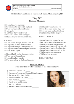


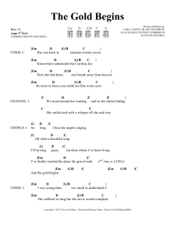


© Copyright 2026