
Modular I/O System ETHERNET TCP/IP 750-342, 750-842 Manual
Modular I/O System ETHERNET TCP/IP 750-342, 750-842 Manual Technical description, installation and configuration 750-129/000-002 Version 2.0.0 ii • General Copyright 2001 by WAGO Kontakttechnik GmbH All rights reserved. WAGO Kontakttechnik GmbH Hansastraße 27 D-32423 Minden Phone: +49 (0) 571/8 87 – 0 Fax: +49 (0) 571/8 87 – 1 69 E-Mail: [email protected] Web: http://www.wago.com Technical Support Phone: +49 (0) 571/8 87 – 5 55 Fax: +49 (0) 571/8 87 – 4 30 E-Mail: [email protected] Every conceivable measure has been taken to ensure the correctness and completeness of this documentation. However, as errors can never be fully excluded we would appreciate any information or ideas at any time. We wish to point out that the software and hardware terms as well as the trademarks of companies used and/or mentioned in the present manual are generally trademark or patent protected. This product includes software developed by the University of California, Berkley and ist contributors. Modular I/O System ETHERNET TCP/IP Table of Contents • iii TABLE OF CONTENTS 1 Important comments ................................................................................. 1 1.1 Legal principles...................................................................................... 1 1.2 Scope...................................................................................................... 2 1.3 Symbols ................................................................................................. 2 1.4 Font conventions.................................................................................... 3 1.5 Number notation .................................................................................... 3 1.6 Abbreviation .......................................................................................... 3 2 The WAGO-I/O-SYSTEM 750................................................................. 4 2.1 System Description ................................................................................ 4 2.2 Installation ............................................................................................. 6 2.3 Electrical Installation ............................................................................. 9 2.4 Power supply........................................................................................ 11 2.5 Manufacturing Number........................................................................ 14 2.6 Technical Data ..................................................................................... 15 3 Fieldbus coupler / controller................................................................... 17 1.1 Fieldbus coupler 750-342 .................................................................... 17 1.2 Fieldbus controller 750-842................................................................. 47 4 I/O modules .............................................................................................. 94 4.1 I/O modules-Review ............................................................................ 95 4.2 Digital Inputs ....................................................................................... 98 4.3 Digital Outputs................................................................................... 132 4.4 Analog Inputs..................................................................................... 164 1.5 Analog Outputs.................................................................................. 209 1.6 Supply and End modules ................................................................... 217 1.7 Terminal blocks for encoder and resolvers........................................ 229 1.8 Special terminal blocks...................................................................... 238 5 ETHERNET ........................................................................................... 261 5.1 Network architecture – Principles and Regulations........................... 262 5.2 Network communication ................................................................... 270 6 Common MODBUS functions .............................................................. 280 6.1 Use of the MODBUS functions ......................................................... 281 6.2 Description of the MODBUS functions ............................................ 282 7 Application examples............................................................................. 302 7.1 Test of MODBUS protocol and fieldbus nodes................................. 302 7.2 Visualization and control using SCADA software............................ 302 8 Application in Explosive Environments .............................................. 305 8.1 Foreword............................................................................................ 305 8.2 Protective measures ........................................................................... 305 8.3 Classification meeting CENELEC and IEC ...................................... 305 8.4 Classifications meeting the NEC 500 ................................................ 310 Modular I/O System ETHERNET TCP/IP iv • Table of Contents 8.5 8.6 9 Identification...................................................................................... 312 Installation regulations....................................................................... 314 Glossary .................................................................................................. 316 10 Literature list ......................................................................................... 327 11 Index........................................................................................................ 328 Modular I/O System ETHERNET TCP/IP Important comments • 1 Legal principles 1 Important comments To ensure fast installation and start-up of the units described in this manual, we strongly recommend that the following information and explanation is carefully read and adhered to. 1.1 Legal principles 1.1.1 Copyright This manual is copyrighted, together with all figures and illustrations contained therein. Any use of this manual which infringes the copyright provisions stipulated herein, is not permitted. Reproduction, translation and electronic and photo-technical archiving and amendments require the written consent of WAGO Kontakttechnik GmbH. Non-observance will entail the right of claims for damages. 1.1.2 Personnel qualification The use of the product detailed in this manual is exclusively geared to specialists having qualifications in PLC programming, electrical specialists or persons instructed by electrical specialists who are also familiar with the valid standards. WAGO Kontakttechnik GmbH declines all liability resulting from improper action and damage to WAGO products and third party products due to non-observance of the information contained in this manual. 1.1.3 Intended use For each individual application, the components supplied are to work with a dedicated hardware and software configuration. Modifications are only admitted within the framework of the possibilities documented in the manuals. All other changes to the hardware and/or software and the non-conforming use of the components entail the exclusion of liability on part of WAGO Kontakttechnik GmbH. Please direct any requirements pertaining to a modified and/or new hardware or software configuration directly to WAGO Kontakttechnik GmbH. Modular I/O System ETHERNET TCP/IP 2 • Important comments Scope 1.2 Scope This manual describes the field bus independent WAGO-I/O-SYSTEM 750 with the fieldbus coupler for ETHERNET TCP/IP along with the programmable fieldbus controller for ETHERNET TCP/IP. Item-No. Components 750-342 EtherNet TCP/IP 10 Mbit 750-842 Contr. EtherNet TCP/IP TCP 10 Mbit 750-4xx...6xx I/O Modules 1.3 Symbols Danger Always observe this information to protect persons from injury. Warning Always observe this information to prevent damage to the device. Attention Marginal conditions must always be observed to ensure smooth operation. ESD (Electrostatic Discharge) Warning of damage to the components by electrostatic discharge. Observe the precautionary measure for handling components at risk. Note Routines or advice for efficient use of the device and software optimization. i More information References to additional literature, manuals, data sheets and INTERNET pages. Modular I/O System ETHERNET TCP/IP Important comments • 3 Font conventions 1.4 Font conventions Italic Names of paths and files are marked in italic. i. e.: C:\programs\WAGO-I/O-CHECK Italic Menu items are marked in bold italic. i. e.: Save \ A backslash between two names markes a sequence of menu items. i. e.: File\New END Keys to press are marked in bold with small capitals. i. e.: ENTER <> Keys are marked bold within angle brackets. i. e.: <F5> Courier Program codes are printed with the font Courier. i. e.: END_VAR 1.5 Number notation Number code Example Code Decimal 100 normal notation Hexadecimal 0x64 C notation Binary ’100’ ’0110.0100’ Within ’, Nibble separated with dots 1.6 Abbreviation AI AO DI DO I/O ID PFC Modular I/O System ETHERNET TCP/IP Analog Input Analog Output Digital Input Digital Output Input/Output Identifier Programmable Fieldbus Controller 4 • The WAGO-I/O-SYSTEM 750 System Description 2 The WAGO-I/O-SYSTEM 750 2.1 System Description 2.1.1 General The WAGO-I/O-SYSTEMconsists of various components which are capable of providing modular and application specific fieldbus nodes for various fieldbusses. A fieldbus node (short: Node) consists in principle of a fieldbus coupler (short: Coupler) or a programmable fielbus controller (short: Controller) at the front end (1), a number of I/O modules (2) and an end module (3) which is placed at the other end. Fig. 2-1: Setting up a fieldbus node with the WAGO-I/O-SYSTEM 2.1.2 g012900x Coupler/Controller (1) The Coupler/Controller forms the link between the fieldbus and the field devices with their I/O functions. All control functions required for the faultless operation of the I/O functions are carried out by the Coupler/Controller. The connection to different fieldbus systems is established by each of the corresponding Coupler/Controller, e.g. for PROFIBUS, INTERBUS, CAN, MODBUS etc. In this way a change of the fieldbus system is possible. The programmable fieldbus controller 750-842 combines the ETHERNET TCP/IP functionality of the fieldbus coupler 750-342 with the functionality of a Programmable Logic Control (PLC). Programming of the application is done with WAGO-I/O-PRO in accordance with IEC 61131-3, covering all 5 programming languages. The programmer can access all fieldbus and I/O data. Modular I/O System ETHERNET TCP/IP The WAGO-I/O-SYSTEM 750 • 5 System Description Characteristics and use of the Controllers: • The use of decentralized control can better support a PLC or PC • Complex applications can be divided into multiple tasks • Programmable response in the event of a fieldbus failure • Signal pre-processing reduces fieldbus transmissions • Peripheral equipment can be controlled directly, resulting in faster system response times • Simple, self-sufficient control 2.1.3 I/O Modules (2) In the I/O modules, the incoming process data is converted. Corresponding to the different requirements, special I/O modules are available for a variety of functions. There are digital and analog inputs and outputs and modules for special functions (Counter modules, Terminal blocks for encoder and resolvers and communication modules). 2.1.4 End Module (3) An End Module is needed for faultless operation of the node. The termination module is always placed as the last module in order to obtain a termination of the fieldbus node. This module has no I/O function. Modular I/O System ETHERNET TCP/IP 6 • The WAGO-I/O-SYSTEM 750 Installation 2.2 Installation 2.2.1 Safty notes ESD (Electrostatic Discharge) The modules are equipped with electronic components which may be destroyed by electrostatic discharge.When handling the modules, ensure that the environment (persons, workplace and packing) is well grounded. Avoid touching conductive components, e.g. gold contacts. Attention Switch off the system prior to working on bus modules! 2.2.2 Mechanical Installation All system components can be snapped directly on a carrier rail in accordance with the European standard EN 50022 (DIN 35). Attention Ensure that the carrier rail is fastened with countersunk head screws or blind rivets as the snap-on foot of the I/O components extends onto the carrier rail. The installation is simple and space saving. All modules have the same shape to minimize the project commitment. The reliable positioning and connection of the coupler and the individual I/O modules is made using a tongue and groove system. Due to the automatic locking, the individual components are securely seated on the rail after installing. Modular I/O System ETHERNET TCP/IP The WAGO-I/O-SYSTEM 750 • 7 Installation To secure the coupler/controller against moving sideways, lock it with the orange colored locking disc on the carrier rail. To lock, insert a screwdriver into the top groove of the locking disc and press. To pull out the fieldbus coupler, release the locking disc by pressing on the bottom groove with a screwdriver and then pull the orange colored unlocking lug. Fig. 2-2: Coupler/Controller and unlocking lug G012912d It is also possible to release an individual I/O module from the unit by pulling the unlocking lug. Fig. 2-3: Releasing a I/O Module p0xxx01x Danger Ensure that an interruption of the ground will not result in a condition which could endanger a person or equipment! Modular I/O System ETHERNET TCP/IP 8 • The WAGO-I/O-SYSTEM 750 Installation Self-cleaning power jumper contacts conduct the supply voltage for the field side. They are located on either side of the modules. The female contacts on the right-hand side of the fieldbus coupler and the bus modules are designed as spring contacts to protect against accidental contact. Male contacts are located on the left-hand side of the bus modules. Pos. 1 Pos. 2 Fig. 2-4: Power Jumper Contacts g01xx00d Danger The power contacts have sharp-edges. Handle the module carefully to prevent injury. Attention Please take into consideration that some bus modules have no or only some power jumper contacts. The design of some modules does not physically allow for assembling them in rows as the grooves for the male contacts are closed at the top. The data contacts are designed as self-cleaning gold spring contacts which automatically produce a secure connection. Fig. 2-5: Data contacts p0xxx07x Warning Do not connect the I/O module to gold spring contacts in order to avoid tarnishing or scratching! Modular I/O System ETHERNET TCP/IP The WAGO-I/O-SYSTEM 750 • 9 Electrical Installation 2.3 Electrical Installation 2.3.1 Wire Connection Conductors with a cross section of 0.08 to 2.5 mm² (AWG 28-12) can be connected using a CAGE CLAMP connection to achieve a vibration resistant, fast and maintenance free connection. To actuate CAGE CLAMP enter an actuation tool in the opening above the connection. Following this, enter the conductor in the corresponding opening. The conductor is clamped securely with the removal of the actuation tool. Fig. 2-6: Inserting conductor end p0xxx06x The clamping force adjusts automatically to the cross section. The full surface of the CAGE CLAMP pressure is applied against the conductor without damaging it. Conductor deformation is compensated for and self-loosening is avoided. The transition point between the conductor and the CAGE CLAMP is protected against corrosive influences. The connection can be made quickly and is also maintenance free, saving the costs for a periodic checking of terminal connections. Two carrier rail contacts responsible for the electrical contact between the grounded carrier rail and the controller are fitted underneath the coupler/controller. Attention Ensure a perfect contact point between carrier rail contacts and carrier rail. The carrier rail must be grounded. Modular I/O System ETHERNET TCP/IP 10 • The WAGO-I/O-SYSTEM 750 Electrical Installation 2.3.2 Change fuse Some Power supply modules of the WAGO-I/O-SYSTEM 750 are equipped with a fuse holder. To isolate the modules to the right of the power supply, the fuse can be removed from the fuse holder. For this insert a screw driver into one of the slits available on each side and lift the holder. Fig. 2-7: Removing the fuse holder p0xxx05x The fuses can be removed from or inserted into the fuse holder cover. Then push the fuse holder back into the original position. Fig. 2-8: Opening the fuse holder p0xxx03x Fig. 2-9: Change fuse p0xxx04x Modular I/O System ETHERNET TCP/IP The WAGO-I/O-SYSTEM 750 • 11 Power supply 2.4 Power supply 1 2 750-400 750-410 750-403 750-612 750-512 750-512 750-513 750-616 750-454 750-467 750-461 750-550 750-610 750-552 750-630 750-650 750-600 ~ 24V 24V 230V Fig. 2-10: Power supply 24V g01xx02x 1 – Power supply System 2 – Power supply Field-side The power supply on the field side is electrically isolated from the system supply. In this manner sensors and actuators can be supplied and fused by a separate voltage source. If a non-regulated power supply is used for the coupler/controller electronics 24 V voltage supply, it must be filtered through a capacitor (200 µF per 1 A load current). A back-up capacitor module (Order-No. 288-824) was developed for the WAGO-I/O-SYSTEM. This module serves to regulate a noisy 24 V DC voltage supply and to keep the ripple voltage within specified limits. These fluctuations could be caused by a voltage interruption on the primary side, a secondary side overload or the switching of ”non quenched“ inductance or capacitance. Warning The supply module’s + and –, which are permanently integrated on the buscouplers, must be supplied with 24 V DC only. 120 V AC and 230 V AC can only be supplied via modules 750-609, 750-611 and 750-612! Warning The ground (earth) field side contact should be disconnected when testing the isolation. Otherwise the results could be wrong or the module could be destroyed. Modular I/O System ETHERNET TCP/IP 12 • The WAGO-I/O-SYSTEM 750 Power supply 2.4.1 System supply voltage The system supply voltage (24 V DC) is filtered with a voltage regulator before powering the coupler electronics as well as to the internal bus. Electrical isolation from the external fieldbus system depends on the type of Coupler/Controller. The internal bus includes the internal communication between the coupler/controller and the bus modules as well as the power supply for the bus modules. The power supply is limited to a maximum value. This value depends on the type of Coupler/Controller. If the sum of the internal power consumption of all bus modules exceeds this value, it is necessary to add additional internal system supply modules (Order-No. 750-613). The control electronics in the bus modules are powered by snap-fit mounting the bus modules using the internal bus contacts. A reliable contact is assured by the gold plated, self cleaning slide contacts. The removal of a bus module will cause an interruption in communication to the following bus modules. The coupler/controller identifies the interruption point and displays a corresponding fault message. Warning Removing or inserting the I/O modules with the voltage applied can lead to undefined conditions. For this reason only remove the I/O modules when isolated from the power supply! Modular I/O System ETHERNET TCP/IP The WAGO-I/O-SYSTEM 750 • 13 Power supply 2.4.2 Supply Voltage Field Side The voltage is automatically supplied when the I/O modules are snapped together. Self-cleaning power jumper contacts (P.J.C.s) ensure safe connections. The current capacity of the power contacts is 10 A max. The PE contact is a preceding ground (earth) contact corresponding to the standards which can be used as a protective earth. The contact has a leakage capacity of 125 A. Warning Produce a low impedance connection from the carrier rail to the PE contact point in the cabinet. Attention Depending on the I/O function, some modules do not have P.J.C.s. It is important to note this when assembling a node. Many modules require field side power, many do not. Please review the circuit diagrams of the individual modules. An additional power supply module may be necessary. Refer to the individual terminal/module data sheets! When adding a power supply module, the field supply is always interrupted at the power contacts. From this point a new power supply is made, which can also include a potential change. This feature guarantees a high degree of system flexibility. Modular I/O System ETHERNET TCP/IP 14 • The WAGO-I/O-SYSTEM 750 Manufacturing Number 2.5 Manufacturing Number The production number is part of the lateral marking on the component. The number contains the production date, the software version and the hardware of the component. 2DI 24V DC 3.0ms Hansastr. 27 D-32423 Minden 0.08-2.5mm 0V 24V 24246 0901--02----03 CL I DIV 2 24V DC Grp. A B C D AWG 28-14 op temp code T4A 55°C max ambient LISTED 22ZA AND 22XM ITEM-NO.:750-400 2 DI1 Di2 II 3 G KEMA 01ATEX1024 X EEx nA II T4 PATENTS PENDING Manufacturing Number 0 9 0 1 - - 0 2 Calendar week Year Software version Hardware version Fig. 2-11: Manufacturing Number g01xx09e The remaining digits and characters represent internal information for WAGO Kontakttechnik GmbH. As of calendar week 43/2000, the production number is also printed on the cover of the configuration and programming interface of the fieldbus coupler or controller. Modular I/O System ETHERNET TCP/IP The WAGO-I/O-SYSTEM 750 • 15 Technical Data 2.6 Technical Data Mechanic Material Polycarbonate, Polyamide 6.6 Installation on DIN 35 with interlock modular by double featherkey-dovetail Mounting position any position Length of entire node ≤ 831 mm Marking marking label type 247 and 248 paper marking label 8 x 47 mm Wire range Wire range CAGE CLAMP® Connection 0,08 mm² ... 2,5 mm² AWG 28-14 8 – 9 mm Stripped length Contacts Power jumpers contacts blade/spring contact self-cleaning Current via power contactsmax 10 A Voltage drop at Imax < 1 V/64 modules Data contacts slide contact, hard gold plated 1,5µ, self-cleaning Environmental conditions Operating temperature 0 °C ... 55 °C Storage temperature -20 °C ... +85 °C Relative humidity 95 % without condensation Resistance to harmful substances acc. to IEC 60068-2-42 and IEC 60068-2-43 Special conditions Ensure that additional measures for components are taken, which are used in an environment involving: – dust, caustic vapors or gases – ionizing radiation. Mechanical strenght Modular I/O System ETHERNET TCP/IP Vibration resistance acc. to IEC 60068-2-6 Shock resistance acc. to IEC 60068-2-27 Free fall acc. to IEC 60068-2-32 ≤ 1m (module in original packing) 16 • The WAGO-I/O-SYSTEM 750 Technical Data Safe electrical isolation Air and creepage distance acc. to IEC 60646-1 Degree of protection Degree of protection IP 20 Electromagnetic compatibility* Directive Test values Strength class Evaluation criteria Immunity to interference acc. to EN 50082-2 (95) EN 61000-4-2 4kV/8kV EN 61000-4-3 10V/m 80% AM EN 61000-4-4 2kV EN 61000-4-6 10V/m 80% AM Emmission to interference acc. to EN 50081-2 (94) B (3) A (3/4) B (3) A Measuring distance G% 9P EN 55011 (2/4) (30m) Class A G% 9P * Exception: 750-630, 750-631 Dimensions 01 02 A C B D A C B D A B C D A B A C B D C D 24V 0V + - - 100 + 65 51 Fig. 2-12: Dimensions 12 24 64 35 PE PE g01xx05d Modular I/O System ETHERNET TCP/IP Fieldbus coupler / controller • 17 Fieldbus coupler 750-342 3 Fieldbus coupler / controller 3.1 Fieldbus coupler 750-342 This chapter includes: 3.1.1 3.1.2 3.1.2.1 3.1.2.2 3.1.2.3 3.1.2.4 3.1.2.5 3.1.2.6 3.1.3 3.1.4 3.1.4.1 3.1.4.2 3.1.4.3 3.1.5 3.1.5.1 3.1.5.2 3.1.5.3 3.1.6 3.1.6.1 3.1.6.2 3.1.6.3 3.1.6.4 3.1.6.5 3.1.6.6 3.1.7 3.1.7.1 3.1.7.2 3.1.7.3 3.1.7.4 3.1.8 3.1.8.1 3.1.8.2 3.1.9 Modular I/O System ETHERNET TCP/IP Description ..................................................................................... 18 Hardware ........................................................................................ 19 View......................................................................................... 19 Device supply .......................................................................... 20 Fieldbus connection ................................................................. 20 Display elements...................................................................... 21 Configuration interface ............................................................ 21 Hardware address (MAC-ID) .................................................. 21 Operating system ............................................................................ 22 Process image ................................................................................. 23 Example of a process input image ........................................... 24 Example of a process output image ......................................... 25 Process data architecture for MODBUS/TCP ......................... 26 Data exchange................................................................................. 31 Memory areas .......................................................................... 32 Addressing ............................................................................... 32 Data exchange between MODBUS master and I/O modules .. 34 Starting up ETHERNET TCP/IP fieldbus nodes............................ 35 Note the MAC-ID and establish the fieldbus node.................. 35 Connecting PC and fieldbus node............................................ 35 Determining IP addresses ........................................................ 36 Allocating the IP address to the fieldbus node ........................ 36 Testing the function of the fieldbus node ................................ 39 Reading out the information as HTML pages.......................... 40 LED Display ................................................................................... 41 Blink code................................................................................ 41 Fieldbus status ......................................................................... 42 Node status............................................................................... 42 Fault message via blink code from the I/O-LED ..................... 43 Fault behavior................................................................................. 45 Fieldbus failure ........................................................................ 45 Internal bus fault ...................................................................... 45 Technical Data................................................................................ 46 18 • Fieldbus coupler 750-342 Description 3.1.1 Description The fieldbus coupler 750-342 displays the peripheral data of all I/O modules in the WAGO-I/O-SYSTEM 750 on ETHERNET. All sensor input signals are grouped in the coupler (slave) and transferred to the higher ranking controls (master) via the fieldbus. Process data linking is performed in the higher ranking controls. The controls put out the resulting data to the actuators via the bus and the node. To be able to transmit process data via ETHERNET, the coupler supports a series of network protocols. Process data are exchanged with the aid of the MODBUS/TCP protocol. Once the ETHERNET TCP/IP fieldbus coupler is connected, the coupler detects all I/O modules connected to the node and creates a local process image on this basis, which can be a mixed arrangement of analog (word-by-word data exchange) and digital (bit-by-bit data exchange) modules. The local process image is subdivided into an input and an output data area. The data of the analog modules are mapped into the process image in the order of their position downstream of the bus coupler. The bits of the digital modules are grouped into words and also mapped into the process image as soon as mapping of the analog modules is completed. When the number of digital I/O’s exceeds 16 bits, the coupler automatically starts the next word. Also note that all process images start at WORD 0. Information on configuration, status and the I/O data of the fieldbus node are stored in the fieldbus coupler as HTML pages. These pages can be seen via a standard WEB browser by typing the IP address, that you assigned the coupler, into the Address field of your web browser. Modular I/O System ETHERNET TCP/IP Fieldbus coupler 750-342 • 19 Hardware 3.1.2 Hardware 3.1.2.1 View 01 02 ETHERNET fieldbus connection RJ 45 ON A LINK B C D TxD/RxD 24V 0V ERROR + + - - supply via power jumper contacts 24V 750-342 I/O status voltage supply -power jumper contacts -system data contacts supply 24V 0V 0V flap open configuration interface power jumper contacts Fig. 3-1: Fieldbus coupler ETHERNET TCP/IP G034200e The fieldbus coupler is comprised of: • Supply module which includes the internal system supply as well as power jumper contacts for the field supply via I/O module assemblies. • Fieldbus interface with the bus connection RJ 45 • Display elements (LED’s) for status display of the operation, the bus communication, the operating voltages as well as for fault messages and diagnosis • Configuration Interface • Electronics for communication with the I/O modules (internal bus) and the fieldbus interface Modular I/O System ETHERNET TCP/IP 20 • Fieldbus coupler 750-342 Hardware 3.1.2.2 Device supply The supply is made via terminal bocks with CAGE CLAMP® connection. The device supply is intended both for the system and the field units. Fig. 3-2: Device supply G034201e The integrated internal system supply module generates the necessary voltage to supply the electronics and the connected I/O modules. The fieldbus interface is supplied with electrically isolated voltage from the internal system supply module. 3.1.2.3 Fieldbus connection Connection to the fieldbus is by an RJ45 connector. A category 5, shielded/unshielded twisted pair cable (S-UTP) with an impedance of 100 Ohm ±15% is mandatory as a connecting line for the 10BaseT Interface. The connection point is physically lowered for the coupler/controller to fit in an 80 mm high switch box once connected. The electrical isolation between the fieldbus system and the electronics is achieved by means of DC/DC converters and optocouplers in the fieldbus interface. Contact Signal 1 2 3 4 5 6 7 8 TD + TD RD + RD - Transmit + Transmit Receive + free free Receive free free Fig. 3-3: RJ45-connector and RJ45 connector configuration Modular I/O System ETHERNET TCP/IP Fieldbus coupler 750-342 • 21 Hardware 3.1.2.4 Display elements The operating condition of the fieldbus coupler or node is signaled via light diodes (LED). 01 ETHERNET ON A LINK B 02 C D status voltage supply -power jumper contacts -system TxD/RxD 24V 0V ERROR I/O Fig. 3-4: 3.1.2.5 + + Display elements 750-342 G012901e LED ON LINK TxD/RxD ERROR IO Color green green green red red /green / orange Meaning Fieldbus initialization is correct Link to a physical network exists Data exchange taking place Error on the fieldbus The ’I/O’-LED indicates the operation of the node and signals faults encountered A green Status of the operating voltage – system C green Status of the operating voltage – power jumper contacts Configuration interface The configuration interface used for the communication with WAGO-I/OCHECK or for firmware download is located behind the cover flap. open flap Configuration interface Fig. 3-5: Configuration interface g012945e The communication cable (750-920) is connected to the 4 pole header. 3.1.2.6 Hardware address (MAC-ID) Each WAGO ETHERNET fieldbus coupler is provided from the factory with a unique and internationally unambiguous physical ETHERNET address, also referred to as MAC-ID (Media Access Control Identity). This address is to be found on the rear of the coupler and on an adhesive tear-off label on the side of the coupler. The address has a fixed length of 6 Bytes (48 Bit) and contains the address type, the manufacturer’s ID, and the serial number. Modular I/O System ETHERNET TCP/IP 22 • Fieldbus coupler 750-342 Operating system 3.1.3 Operating system Following is the configuration of the master activation and the electrical installation of the fieldbus station to start up the system. After switching on the supply voltage, the coupler determines the I/O modules and the present configuration. In the event of a fault, the coupler changes to the "Stop" condition. The "I/O" LED flashes red. After a fault free start up, the coupler changes to the "Fieldbus start" status and the "I/O" LED lights up green. Switching on the supply voltage Initialization, Determination of the I/O modules and the configuration, “I/O” LED is blinking red Test o.k.? No Yes Fieldbus coupler is in operating mode “I/O” LED is shining green Fig. 3-6: Operating system 750-342 Stop red “I/O” LED indicates blink code g012920e Modular I/O System ETHERNET TCP/IP Fieldbus coupler 750-342 • 23 Process image 3.1.4 Process image After switching on, the coupler recognizes all I/O modules plugged into the node which supply or wait for data (data width/bit width > 0). Analog and digital I/O modules can be mixed on the same node. Note For the number of input and output bits or bytes of the individually activated I/O modules, please refer to the corresponding I/O module description. The coupler produces an internal process image from the data width and the type of I/O module as well as the position of the I/O modules in the node. It is divided into an input and an output data area. The data of the digital I/O modules is bit orientated, i.e. the data exchange is made bit for bit. The analog I/O modules are representative for all byte orientated I/O modules, i.e. those where the data exchange is made byte for byte. These I/O modules include for example the counter modules, I/O modules for angle and path measurement as well as the communication modules. The data of the I/O modules is separate from the local input and output process image in the sequence of their position after the coupler in the individual process image. First, all the byte oriented bus modules and then the bit oriented bus modules are stored in the process image. The bits of the digital modules are grouped to form bytes. As soon as the number of digital I/O’s exceeds 8 bits, the coupler automatically starts the next byte. Note A process image restructuring may result if a node is changed. In this case the process data addresses also change in comparison with earlier ones. In the event of adding modules, take the process data of all previous modules into account. The coupler provides a storage area of 256 words each (word 0 - 255) for the physical input and output data. Modular I/O System ETHERNET TCP/IP 24 • Fieldbus coupler 750-342 Data exchange Example of a process input image The following figure is an example of a process input image. The configuration comprises of 16 digital and 8 analog inputs. The process image thus has a data length of 8 words for the analog and 1 word for the digital inputs, i.e. 9 words in total. DI DI AI AI DI AI DI AI Ethernet ON LINK TxD/RxD ERROR 750-842 I/O W AGO ßI /O ßSY STE M 3.1.4.1 Input modules Process input image (Word) 750Bit 4 402 402 Bit 1 1 4 472 472 Word1 Word1 Word2 Word2 402 1 4 476 Word1 Word2 402 1 4 476 Word1 Word2 MODBUS addresses Word1 0x0000 Word2 0x0001 Word1 0x0002 Word2 0x0003 Word1 0x0004 Word2 0x0005 0x0006 Word1 0x0007 Word2 0x0008 Highbyte Lowbyte Process input image (Bit) MODBUS addresses 0x0000 0x0001 0x0002 0x0003 0x0004 0x0005 0x0006 0x0007 0x0008 0x0009 0x000A 0x000B DI: Digital Input AI:Analog Input 0x000C 0x000D 0x000E 0x000F Fig. 3-7: Example of a process input image G012914e Modular I/O System ETHERNET TCP/IP Fieldbus coupler 750-342 • 25 Data exchange 3.1.4.2 Example of a process output image The following example for the process output image comprises of 2 digital and 4 analog outputs. It comprises of 4 words for the analog and 1 word for the digital outputs, , i.e. 5 words in total. In addition, the output data can be read back by means of an offset of 200hex (0x0200) added to the MODBUS address. DO AO AO Ethernet ON LINK TxD/RxD ERROR 750-342 W AGO ßI /O ßSY STE M I/O Output modules Process output image (Word) 750 - 501 550 550 Bit 1 Word1 Word1 Bit 2 Word2 Word2 MODBUS addresses 0x0000 / 0x0200 0x0001 / 0x0201 0x0002 / 0x0202 0x0003 / 0x0203 0x0004 / 0x0204 Highbyte Word1 Word2 Word1 Word2 Lowbyte Process input image (Word) MODBUS addresses Word1 Word2 0x0200 0x0201 0x0202 0x0203 0x0204 Word1 Word2 Highbyte Lowbyte Process output image (Bit) MODBUS addresses 0x0000 / 0x0200 0x0001 / 0x0201 Process input image (Bit) MODBUS addresses 0x0200 0x0201 DO: Digital Output AO: Analog Output Fig. 3-8: Example of a process output image Modular I/O System ETHERNET TCP/IP G012915e 26 • Fieldbus coupler 750-342 Data exchange 3.1.4.3 Process data architecture for MODBUS/TCP For some bus modules or their variations the process data architecture is specific for the fieldbus coupler used. In the case of the ETHERNET coupler with MODBUS/TCP, the control/status byte is always masked in addition to the data bytes. This is required for the two-directional data exchange of the bus module with the higher-ranking control system. The control byte is transmitted from the control system to the module and the status byte from the module to the control system. This allows, for example, the display of overshooting or undershooting of the area. Attention Please refer to the respective bus module description in Chapter 4 "I/O modules" for the specific architecture of the control/status byte. The following shows the representation of some selected modules in the process image. In the examples, the order in which the modules are physically arranged in the node reflects the order in the image table starting with register address 0x0000. If the module is at any other position in the fieldbus node, the process data of all previous byte-wise oriented modules has to be taken into account, resulting in a basic register address for the module in the process image. The mentioned offset will be added to this basic address for addressing its process data words. If an analog input or output module is added, it takes up 2 x 16 Bit input of output data. Therefore the first available digital point would be at word 2 keeping in mind that all process image addressing starts at WORD 0. With the ETHERNET fieldbus coupler with MODBUS/TCP TCP, the process image is word aligned (word-alignment) and the control/status byte is always a low byte. Modular I/O System ETHERNET TCP/IP Fieldbus coupler 750-342 • 27 Data exchange 3.1.4.3.1 750-404, /000-00X Counter modules This process data architecture holds true for the counter modules 750-404, 750-404/000-001, 750-404/000-002 and 750–404/000-004. Item-No.: Description: 750-404 Up/Down Counter 750-404/000-001 2 Channel Up Counter with enable input 750-404/000-002 Peak Time Counter 750-404/000-004 Up/Down Counter (switching outputs) The data format of the counter modules five bytes is mapped out by the module as four data bytes and one additional control/status byte. The module supplies a 32 bit counter-output. Three words each in the process image are occupied with word-alignment. Address Bytes Offset High Comment Module Low 0 C/S Control-/ Status byte 1 D1 D0 2 D3 D2 Data bytes 3 User data User data Data bytes 4 User data User data Data bytes ... ... ... ... Module 1: 750-404, 750-404/000-001, 750-404/000-002, 750-404/000-004 Module 2: Analog module Channel 1 Module 2: Analog module Channel 2 ... The input bytes D0 to D3 form the 32 bit counter-output. In the output bytes D0 to D3, the initial value of the counter can be set. 3.1.4.3.2 750-404/000-005 2 Channel Up Counter 16 Bit The data format of the counter modules five bytes is mapped out by the module as four data bytes and one additional control/status byte. Three words each in the process image are occupied with word-alignment . Address Bytes Offset High Module Low 0 Modular I/O System ETHERNET TCP/IP Comment C/S Control/ Statusbyte Module 1: 750-404/000-005 1 D1 D0 Data bytes Counter 1 2 D3 D2 Data bytes Counter 2 3 User data User data Data bytes Module 2: Analog module Channel 1 4 User data User data Data bytes Module 2: Analog module Channel 2 ... ... ... ... ... 28 • Fieldbus coupler 750-342 Data exchange The input bytes D0 and D1 form the 16 bit reading of counter 1 and the input bytes D2 and D3 form the 16 bit reading of counter 2. When setting the counter, the load value of counter 1 is transferred in the output bytes D0 and D1. The load value of counter 2 is transferred respectively in the output bytes D2 and D3. 3.1.4.3.3 750-511, /000-002 2-Channel Digital Pulsewidth module This process data architecture holds true for the 2 Channel Pulsewidth modules 750-511 and 750–511/000-002. Item-No.: Description: 750-511 2DO 24V DC 0.1A Pulsewidth 750-511/000-002 2DO 24V DC 0.1A Pulsewidth 100Hz The process image of the 750-511 and 750-511/000-002 appears with 6 bytes of input and 6 bytes of output data. Four words in the process image are occupied with word-alignment . Address Bytes Offset High Module Low 0 1 Comment D1-0 2 C/S-0 Control / Status byte D0-0 Data bytes C/S-1 Control / Status byte Module 1 Channel 1: 750-511, 750-511/000-002 Module 1 Channel 2: 750-511, 750-511/000-002 3 D1-1 D0-1 Data bytes 4 User data User data Data bytes Module 2: Analog Module Channel 1 5 User data User data Data bytes Module 2: Analog Module Channel 2 ... ... ... ... ... 3.1.4.3.4 750-630, /000-00X SSI encoder interface 24 Bit This process data architecture holds true for the SSI encoder interface modules 750-630, 750-630/000-001 and 750–630/000-006. Item-No.: Description: 750-630 SSI encoder interface 24Bit, 125kHz Gray code, alternative Data format 750-630/000-001 SSI encoder interface 24Bit, 125kHz Binary code, alternative Data format 750-630/000-006 SSI encoder interface 24Bit, 250kHz Gray code, alternative Data format Modular I/O System ETHERNET TCP/IP Fieldbus coupler 750-342 • 29 Data exchange The module is seen like an analog input with 2 x 16 Bit input data, i.e. with a total of 4 bytes user data. With word-alignment 2 words are used in the input area of the local process image. Address Bytes Offset High Comment Module Low 0 D1 D0 1 D3 D2 Data bytes Module 1: 750-630, 750-630/000-001, 750-630/000-006 2 User data User data Data bytes Module 2: Analog module Channel 1 3 User data User data Data bytes Module 2: Analog module Channel 2 ... ... ... ... ... 3.1.4.3.5 750-631, /000-001 Incremental Encoder Interface This process data architecture holds true for the Incremental Encoder Interface modules 750-631 and 750–631/000-001. Item-No.: Description: 750-631 Incremental encoder interface, 4 times sampling 750-631/000-001 Incremental encoder interface, 1 times sampling The bus module 750-631 and 750-631/000-001 002 appears with 6 bytes of input and 6 bytes of output data and occupying 4 words each with word-alignment. Address Bytes Offset High Module Low 0 1 Comment C/S D1 3 D0 Control / Status byte ead/set counter word (D2)*) (period) Module 1: 750-631, 750-631/000-001 4 D4 D3 read latch word 5 User data User data Data bytes Module 2: Analog module Channel 1 6 User data User data Data bytes Module 2: Analog module Channel 2 ... ... ... ... ... In the low byte, the control/status byte is on offset 0. The data word D0/D1 contains the counter word (read/set), whereas the data word D3/D4 contains the latch word (read). *) In the operating mode of permanent period measurement, the period duration is in D2 together with D3/D4. Modular I/O System ETHERNET TCP/IP 30 • Fieldbus coupler 750-342 Data exchange 3.1.4.3.6 750-650 RS232 Interface module, 750-651 TTY-,20 mA Current Loop, 750-653 RS485 Interface module This process data architecture holds true for the modules 750-650, 750-651 and 750–653. Item-No.: Description: 750-650 RS 232 C Interface 9600,n,8,1 750-651 TTY Interface, 20 mA Current Loop 750-653 RS485 Interface The modules appear on the bus as a combined analog input and output module with 3 x 16-bit input and output data, i.e. with a total of 4 bytes user data, occupying 2 words each with word-alignment. Address Bytes Offset High Comment Module Low Data byte Control / Status byte Module 1: 750-650, 750-651, 750-653 0 D0 C/S 1 D2 D1 Data bytes 2 User data User data Data bytes Module 2: Analog module Channel 1 3 User data User data Data bytes Module 2: Analog module Channel 2 ... ... ... ... ... 3.1.4.3.7 750-650/000-001 RS232 Interface module 5 Byte The RS232 interface module 750-650 can also be operated with a data format of 5 bytes and one Control/Status byte, i.e. a total of 6 bytes user data. For this data format, order the variation with the part number 750-650/000-001, occupying 3 words each with word-alignment in the input and output area of the process image. Address Bytes Offset High Comment Module Low Data byte Control / Status byte 0 D0 C/S 1 D2 D1 2 D4 D3 3 User data User data Data bytes Module 2: Analog module Channel 1 4 User data User data Data bytes Module 2: Analog module Channel 2 ... ... ... ... ... Module 1: 750-650/000-001 Data bytes Modular I/O System ETHERNET TCP/IP Fieldbus coupler 750-342 • 31 Data exchange 3.1.5 Data exchange Process data exchange with the ETHERNET TCP/IP fieldbus coupler occurs via the MODBUS/TCP protocol. MODBUS/TCP works according to the master/slave principle. The master is a superimposed control unit, i.e. a PC or a PLC device. The ETHERNET TCP/IP couplers of the WAGO-I/O-SYSTEM are slave devices. The master makes a query for communication. Through adressing, this query can be sent to a specific node. The nodes receive the query and return a response to the master, depending on the kind of query. A coupler can communicate with a certain number of simultaneous connections (socket connections) to other network subscribers: • 1 connection for HTTP (reading HTML pages from coupler) and • 3 connections via MODBUS/TCP (reading or writing input and output data from coupler). The maximum number of simultaneous connections cannot be exceeded. If further connections are to be made, terminate existing connections beforehand. For a data exchange, the ETHERNET TCP/IP fieldbus coupler is equipped with two interfaces: • the interface to fieldbus (-master) and • the interface to the bus modules. Data exchange takes place between MODBUS master and the bus modules. The master accesses the bus module data via implemented MODBUS functions. Modular I/O System ETHERNET TCP/IP 32 • Fieldbus coupler 750-342 Data exchange 3.1.5.1 Memory areas fieldbus coupler memory area for input data word 0 I/O modules 1 input modules fieldbus master word 255 memory area for output data word 0 2 output modules I O word 255 Fig. 3-9: Memory areas and data exchange for a fieldbus coupler g012939e The coupler process image contains the physical data of the bus modules in a storage area for input data and in a storage area for output data (word 0 ... 255 each). (1) The input module data can be read from the fieldbus side. (2) In the same manner, writing on the output modules is possible from the fieldbus side. In addition, all output data of the ETHERNET TCP/IP coupler are mirror imaged on a storage area with the address offset 0x0200. This allows to read output values back by adding 0x0200 to the MODBUS address. 3.1.5.2 Addressing 3.1.5.2.1 Addressing the I/O modules The arrangement of the I/O modules in a node is optional. When addressing, first of all the more complex modules (modules occupying 1 or more bytes) are taken into account in accordance with their physical order behind the fieldbus coupler. As such, they occupy the addresses starting with word 0. Following this, the data of the other modules (modules occupying less than 1 byte) follow, grouped into bytes. In accordance with the physical byte-wise order this data is used to fill up the bytes. As soon as a full byte is occupied by the bit-oriented modules, the next byte is automatically started. Modular I/O System ETHERNET TCP/IP Fieldbus coupler 750-342 • 33 Data exchange Note For the number of input and output bits and/or bytes of the individual activated bus modules, please refer to the pertaining descriptions of the bus modules. Note Once a node is modified, a new architecture of the process image can result. As such, the address of the process data will alsochange. In the event of adding modules, the process data of all previous modules has to be taken into account. Data width :RUGFKDQQHO Data width = 1 Bit / channel Analog input modules Digital input modules Analog output modules Digital output modules Input modules for thermal elements Digital output modules with diagnosis (2 Bit / channel) Input modules for resistance sensors Power supply modules with fuse holder / diagnosis Pulse width output modules Solid State power relay Interface module Relay output modules Up/down counter I/O modules for angle and path measurement Table 3.1: I/O module data width 3.1.5.2.2 Address range Address range for I/O module data: Datawidth Address Bit Byte Word 0.0 ... 0 0 0.8... 0.15 1 1.0 ... 1.7 2 1 1.8... 1.15 3 ..... ..... 254.0 ... 254.8... 254.7 254.15 508 509 255.0 ... 255.7 510 ..... 254 255 255.8... 255.15 511 Table 3.2: Address range for the I/O module data The register functions are to be found as from 0x1000 and can be addressed along with the implemented MODBUS function codes (read/write). Modular I/O System ETHERNET TCP/IP 34 • Fieldbus coupler 750-342 Data exchange 3.1.5.3 Data exchange between MODBUS master and I/O modules The data exchange between the MODBUS master and the I/O modules is made by the implemented MODBUS functions in the coupler with reading and writing in bits or bytes. The controller handles four different types of process data: • • • • Input words Output words Input bits Output bits The word for word access to the digital input and output modules is made in accordance with the following table: Digital inputs/ outputs Process data word 16. 15. 14. 13. 12. 11. 10. 9. 8. 7. Bit 15 Bit 7 Bit Bit 6 5 Bit 14 Bit 13 Bit 12 Bit 11 Bit 10 Bit 9 Bit 8 6. 5. 4. 3. 2. 1. Bit 4 Bit 3 Bit 2 Bit 1 Bit 0 Table 3.3: Allocation of digital inputs/outputs to process data word acc. Intel format The outputs can be read back by adding 0x0200 to the MODBUS address. The register functions made available in the coupler, can be addressed by the MODBUS master along with the implemented MODBUS function codes (read/write). To this effect, the individual register address is entered in place of the address of a module channel. MODBUS master 0x000 PII 0x0FF 0x000 (0x200) PIO 0x0FF (0x2FF) Outputs Inputs I/O modules PII = Process Input Image PIO = Process Output Image Fieldbus Coupler Fig. 3-10: Data exchange between the MODBUS master and I/O modules g012927e Modular I/O System ETHERNET TCP/IP Fieldbus coupler 750-342 • 35 Starting up ETHERNET TCP/IP fieldbus nodes 3.1.6 Starting up ETHERNET TCP/IP fieldbus nodes This chapter shows the step-by-step procedure for starting up a WAGO ETHERNET TCP/IP fieldbus node. The following also contains a description of how to read out the coupler-internal HTML pages. Attention This description is given as an example and is limited to the execution of a local startup of an individual ETHERNET fieldbus node with a computer running under windows which is not connected to a network. Direct Internet connection should only be performed by an authorized network administrator and is, therefore, not described in this manual. The procedure contains the following steps: 1. 2. 3. 4. 5. 6. 3.1.6.1 Noting the MAC-ID and establishing the fieldbus node Connecting the PC and fieldbus node Determining the IP address Allocation of the IP address to the fieldbus node Function of the fieldbus tests Reading out information as HTML pages Note the MAC-ID and establish the fieldbus node Before establishing your fieldbus node, please note the hardware address (MAC-ID) of your ETHERNET fieldbus coupler. This is located on the rear of the fieldbus coupler and on the self-adhesive tearoff label on the side of the fieldbus coupler. MAC-ID of the fieldbus coupler will be in this format: ----- ----- ----- ----- ----- -----. 3.1.6.2 Connecting PC and fieldbus node Connect the assembled ETHERNET TCP/IP fieldbus node via a hub or directly to the PC using a 10Base-T cable. Attention For a direct connection, a crossover cable is required instead of a parallel cable. Now start the PC, functioning as master and BootP server, and switch on the voltage supply on the fieldbus coupler (DC 24 V power pack). Once the operating voltage has been switched on, the initialization starts. The fieldbus coupler determines the configuration of the bus modules and creates the process image. During the startup the ’I/O’ LED (Red) flashes at high frequency. When the ’I/O’ LED and the ’ON’ LED light up green, the fieldbus coupler is ready for operation. If an error has occurred during startup, it is indicated as an error code by the ’I/O’-LED flashing (red). Modular I/O System ETHERNET TCP/IP 36 • Fieldbus coupler 750-342 Starting up ETHERNET TCP/IP fieldbus nodes 3.1.6.3 Determining IP addresses If your PC is already connected to an ETHERNET network, it is very easy to determine the IP address of your PC. To do this, proceed as follows: 1. Go to the Start menu on your screen, menu item Settings and click on Control Panel. 2. Double click the icon Network. The network dialog window will open. 3. - Under Windows NT: Select the register: Protocols and mark the entry TCP/IP protocol. - Under Windows 9x: Select the register: Configuration and mark the entry TCP/IP network card. Attention If the entry is missing, please install the respective TCP/IP component and restart your PC. The Windows-NT installation CD, or the installations CD for Windows 9x is required for the installation. 4. Subsequently, click the button "Properties...". The IP address and the subnet mask are found in the ‘IP address’ tab.If applicable, the gateway address of your PC is found in the ‘Gateway’ tab. 5. Please write down the values: IP address PC: ----- . ----- . ----- . ----- Subnet mask: ----- . ----- . ----- . ----- Gateway: ----- . ----- . ----- . ----- 6. Now select a desired IP address for your fieldbus node. Attention When selecting your IP address, ensure that it is in the same local network in which your PC is located. 7. Please note the IP address you have chosen: IP address fieldbus node: ----- . ----- . ----- . ----- 3.1.6.4 Allocating the IP address to the fieldbus node The following describes how to allocate the IP address for the fieldbus node using the WAGO BootP server by way of an example. You can download a free copy from WAGO over the Internet under: http://www.wago.com/wagoweb/usa/eng/support/downloads/index.htm. Modular I/O System ETHERNET TCP/IP Fieldbus coupler 750-342 • 37 Starting up ETHERNET TCP/IP fieldbus nodes Note The IP address can be allocated under other operating systems (i.e. under Linux) as well as with any other BootP servers. Attention The IP address can be allocated in a direct connection via a crossover cable or via a parallel cable and a hub. An allocation over a switch is not possible. BootP table Note Prerequisite for the following steps is the correct installation of the WAGO BootP server. 1. Go to the Start menu, menu item Programs / WAGO Software / WAGO BootP Server and click on WAGO BootP Server configuration. An editable table will appear: "bootptab.txt". This table displays the data basis for the BootP server. Directly following the list of all notations used in the BootP table there are two examples for the allocation of an IP address. "Example of entry with no gateway" and "Example of entry with gateway". Fig. 3-11: BootP table p012908e The examples mentioned above contain the following information: Declaration node1, node2 ht=1 Meaning Any name can be given for the node here. Specify the hardware type of the network here. The hardware type for ETHERNET is 1. (The numbers are described in RFC1700) ha=0030DE000100 Specify the hardware address or the MAC-ID of the ETHERNET ha=0030DE000200 fieldbus coupler (hexadecimal). ip= 10.1.254.100 Enter the IP address of the ETHERNET fieldbus coupler (decimal) ip= 10.1.254.200 here. T3=0A.01.FE.01 Specify the gateway IP address here. Write the address in hexadecimal form. sm=255.255.0.0 In addition enter the Subnet-mask of the subnet (decimal), where the ETHERNET fieldbus coupler belongs to. Modular I/O System ETHERNET TCP/IP 38 • Fieldbus coupler 750-342 Starting up ETHERNET TCP/IP fieldbus nodes No gateway is required for the local network described in this example. Therefore, the first example: "Example of entry with no gateway" can be used. 2. Move the mouse pointer to the text line: "node1:ht=1:ha=0030DE000100:ip=10.1.254.100" and mark the 12 character hardware address which is entered after ha=... Enter the MAC-ID of your own network coupler. 3. If you want to give your fieldbus node a name, delete the name "node1" and enter any name in its place. 4. To assign the coupler a desired IP address, mark the IP address specified in the example which is entered after ip=... Replace it with the IP address you have selected. 5. Because the second example is not necessary at present, insert a “#” in front of the text line of the second example: "# node2:hat=1:ha=003 0DE 0002 00:ip=10.1.254.200:T3=0A.01.FE.01", so that this line will be ignored. Note To address more fieldbus nodes, enter a corresponding text line showing the corresponding entries for each node. 6. Save the altered settings in this text file "bootptab.txt". To do this go to the File menu, menu item Save, and close the editor. BootP Server 7. Now open the dialog window for the WAGO BootP server by going to the Start menu on your screen surface, menu item Program / WAGO Software / WAGO BootP Server and click on WAGO BootP Server. 8. Click on the "Start" button in the opened dialog window. This will activate the inquiry/response mechanism of the BootP protocol. A series of messages will be displayed in the BootP server. The error messages indicate that some services (i.e. port 67, port 68) in the operating system have not been defined. Modular I/O System ETHERNET TCP/IP Fieldbus coupler 750-342 • 39 Starting up ETHERNET TCP/IP fieldbus nodes Fig. 3-12: Dialog window of the WAGO BootP server with messages g012909d 9. Now it is important to restart the coupler by resetting the hardware . This ensures that the new IP address will be accepted by the coupler. To do this, cycle power to the fieldbus coupler for approx. 2 seconds. Following this, the IP address in the coupler is permanently stored and maintained even once the coupler is removed or following a longer voltage failure. 10. Subsequently, click on the "Stop" button and then on the "Exit" button, to close the BootP Server again. 3.1.6.5 Testing the function of the fieldbus node 1. To test the communication with the coupler and the correct assignment of the IP address call up the DOS prompt under Start menu / Program / MSDOS Prompt. 2. Enter the command: "ping" with the IP address you have assigned in the following form: ping [space] XXXX . XXXX . XXXX . XXXX (=IP address). Example: ping 10.1.254.202 Fig. 3-13: Example for the function test of a fieldbus node P012910e 3. When the Return key has been pressed, your PC will receive a response from the coupler, which will then be displayed in the DOS prompt. If the error message: "Timeout" appears instead, please compare your entries again to the allocated IP address. 4. When the test has been performed successfully, you can close the DOS prompt. The network node has now been prepared for communication. Modular I/O System ETHERNET TCP/IP 40 • Fieldbus coupler 750-342 Starting up ETHERNET TCP/IP fieldbus nodes 3.1.6.6 Reading out the information as HTML pages The information saved in the fieldbus coupler can be read as an HTML page using a web browser. • Information on the fieldbus node (Terminal Status): - Number of digital, analog or complex modules Representation of the process image • Information on the fieldbus coupler (Coupler and Network Details): - Order number Firmware version MAC-ID IP address Gateway address (if applicable) Subnet mask Number of transmitted and received packets • Diagnostic information on the fieldbus coupler (Coupler Status): - Error code Error argument Error description Fig. 3-14: Reading out the information via the HTTP protocol G012916d Please proceed as follows: 1. Open a web browser such as Microsoft Internet-Explorer, Netscape Navigator, ... 2. Simply enter the IP address of your fieldbus node in the address field of the browser and press the Return key. The first HTML page with the information on your fieldbus coupler will be displayed in the browser window. Use the hyperlinks to find out more information. Attention If the pages are not displayed after local access to the fieldbus node, then define in your web browser that, as an exception, no proxyserver is to be used for the IP address of the node. Modular I/O System ETHERNET TCP/IP Fieldbus coupler 750-342 • 41 LED Display 3.1.7 LED Display The coupler possesses several LED’s for displaying the coupler operating status and the complete node status. 01 ETHERNET ON A LINK B 02 C D status voltage supply -power jumper contacts -system TxD/RxD 24V 0V ERROR I/O + + Fig. 3-15: Display elements 750-342 G012901e A differentiation is made between the two groups of LEDs. The first group = fieldbus contains the solid color LEDs having the designation ON (green), LINK (green), TxD/RxD (green) and ERROR (red) indicating the operating status of the communication via ETHERNET. The second group = internal bus consists of the three-color I/O LED (red/green/orange). This LED is used to display the status of the internal bus and i. e. the status of the fieldbus node. LEDs located on the right-hand side in the coupler feed section, show the status of the supply voltage. 3.1.7.1 Blink code A blink code displays detailed fault messages. A fault is cyclically displayed using up to 3 different blink sequences. • The first blink sequence (approx. 10 Hz) indicates the fault display. • After a pause a second blink sequence appears (approx. 1 Hz). The number of blink impulses gives the fault code. • The third blink sequence (approx. 1 Hz) appears following a further pause. The number of blink pulses indicates the fault argument. Modular I/O System ETHERNET TCP/IP 42 • Fieldbus coupler 750-342 LED Display 3.1.7.2 Fieldbus status The operating status of the communication via ETHERNET is signalled by means of the top LED group (ON, LINK, TxD/RxD and ERROR). LED Meaning Trouble shooting Fieldbus initialization is correct Fieldbus initialization is not correct, no function or self-test Check the supply voltage (24V and 0V), check the IP configuration Link to a physical network exists No link to a physical network Check the fieldbus connection. ON green OFF LINK green OFF TxD/RxD green OFF Data exchange taking place No data exchange ERROR red OFF 3.1.7.3 Error on the fieldbus No error on the fieldbus, normal operation Node status The operating status of the communication via the internal bus is signalled via the bottom I/O LED. LED Meaning Trouble shooting I/O Green Red Red Fieldbus coupler operating perfectly a) During startup of fieldbus coupler: Internal bus being initialized, Startup displayed by LED flashing fast for approx. 1-2 seconds b) After startup of fieldbus coupler: Errors, which occur, are indicated by three consecutive flashing sequences. There is a short pause between each sequential flash. Evaluate the fault message (fault code and fault argument). The coupler starts up after switching on the supply voltage. The "I/O" LED blinks. The "I/O" LED has a steady light following a fault free run-up. In the case of a fault the "I/O" LED continues blinking. The fault is cyclically displayed by the blink code. Modular I/O System ETHERNET TCP/IP Fieldbus coupler 750-342 • 43 LED Display Switching on the power supply Coupler/Controller starts up “I/O”-LED is blinking No Test o.k.? Yes “I/O” LED 1st flash sequence (Introduction of the error indication) 1st break “I/O” LED 2nd flash sequence Error code (Number of flash cycles) 2nd break “I/O”-LED is shining “I/O” LED 3rd flash sequence Error argument (Number of flash cycles) ready for operation Fig. 3-16: Signalling of the LED for indication of the node status g012911e After clearing a fault, restart the coupler by cycling the power. 3.1.7.4 Fault message via blink code from the I/O-LED Fault argument Fault description Fault code 1: Hardware and Configuration fault 0 1 2 3 4 5 6 EEPROM check sum fault / check sum fault in the parameter area of the flash memory Overflow of the internal buffer memory for the inline code Unknown data type Module type of the flash program memory could not be determined / is incorrect Fault when writing in the FLASH memory Fault when deleting the FLASH memory Changed I/O module configuration determined after AUTORESET Fault code 2: Fault in programmed configuration 0 Incorrect table entry Fault code 3: Internal bus command fault 0 Modular I/O System ETHERNET TCP/IP No error argument is put out. 44 • Fieldbus coupler 750-342 LED Display Fault code 4: Internal bus data fault 0 n* (n>0) Data fault on internal bus or Internal bus interruption on coupler Internal bus interrupted after I/O module n Fault code 5: Fault during register communication n* Internal bus fault during register communication after I/O module n Fault code 6: Fieldbus specific error 1 2 3 4 No reply from the BootP server ETHERNET controller not recognized Invalid MACID TCP/IP initialization error Fault code 7: I/O module is not supported n* I/O module at position n is not supported Fault code 8: not used 0 Fault code 8 is not used. Fault code 9: CPU-TRAP error 1 2 3 4 Illegal Opcode Stack overflow Stack underflow NMI * The number of blink pulses (n) indicates the position of the I/O module. I/O modules without data are not counted (i.e. supply modules without diagnostics). Example for a fault message Fault: The 13th I/O module has been removed. 1. The "I/O" LED starts the fault display with the first blink sequence (approx. 10 Hz). 2. The second blink phase (approx. 1 Hz) follows the first pause. The "I/O" LED blinks four times and thus signals the fault code 4 (internal bus data fault). 3. The third blink sequence follows the second pause. The "I/O ERR" LED blinks twelve times. The fault argument 12 means that the internal bus is interrupted after the 12th I/O module. Supply voltage status There are two green LED’s in the coupler supply section to display the supply voltage. The left LED (A) indicates the 24 V supply for the coupler. The right hand LED (C) signals the supply to the field side, i.e. the power jumper contacts. LED Meaning Trouble shooting Operating voltage for the system exists. No operating voltage for the system. Check the supply voltage (24V and 0V). A green OFF C green OFF Operating voltage for the power jumper contacts exists. No operating voltage for the the power jumper contacts. Check the supply voltage (24V and 0V). Modular I/O System ETHERNET TCP/IP Fieldbus coupler 750-342 • 45 Fault behavior 3.1.8 Fault behavior 3.1.8.1 Fieldbus failure A field bus failure is given i. e. when the master cuts-out or the bus cable is interrupted. A fault in the master can also lead to a fieldbus failure. A field bus failure is indicated when the red "ERROR"-LED is illuminated. If the watchdog is activated, the fieldbus coupler firmware evaluates the watchdog-register in the case of fault free communication, and the coupler answers all following MODBUS TCP/IP requests with the exception code 0x0004 (Slave Device Failure). i 3.1.8.2 More information For detailed information on the Watchdog register see Chaper 6.2.12 "Watchdog (Fieldbus failure)". Internal bus fault An internal bus fault is created, for example, if an I/O module is removed. If this fault occurs during operation the output modules behave in the same manner as an I/O module stop. The "I/O" LED blinks red. The coupler generates a fault message (fault code and fault argument). After clearing the internal bus fault, restart the coupler by cycling the power. The coupler starts up. The transfer of the process data is then resumed and the node outputs are correspondingly set. Modular I/O System ETHERNET TCP/IP 46 • Fieldbus coupler 750-342 Technical Data 3.1.9 Technical Data System data Max. n. of nodes limited by ETHERNET specification Transmission medium Twisted Pair S-UTP 100 Ω cat. 5 Buscoupler connection RJ45 Max. length of fieldbus segment 100 m between hub station and 750-342; max. length of network limited by ETHERNET specification 10 Mbit/s Baud rate Protocols MODBUS/TCP, HTTP, BootP Approvals UL E175199, UL508 Conformity marking Œ Technical Data Max. n. of I/O modules 64 Input process image max. 512 Byte Output process image max. 512 Byte max. n. of socket connections 1 HTTP, 3 MODBUS/TCP Voltage supply DC 24 V (-15 % / + 20 %) Input currentmax 500 mA at 24 V Efficiency of the power supply 87 % Internal current consumption 200 mA at 5 V Total current for I/O modules 1800 mA at 5 V Isolation 500 V system/supply Voltage via power jumper contactsmax DC 24 V (-15 % / + 20 %) Current via power jumper contactsmax DC 10 A Dimensions (mm) B x H x T 51 x 65* x 100 (*from upper edge of DIN 35 rail) Weight approx. 195 g EMC Immunity to interference acc. to EN 50082-2 (95) EMC Emission of interference acc. to EN 50081-2 (94) Modular I/O System ETHERNET TCP/IP Fieldbus coupler /controller • 47 Fieldbus controller 750-842 3.2 Fieldbus controller 750-842 This chapter includes: 3.2.1 Description ..................................................................................... 48 3.2.2 Hardware ........................................................................................ 49 1.1.1.1 View......................................................................................... 49 1.1.1.2 Device supply .......................................................................... 50 1.1.1.3 Fieldbus connection ................................................................. 51 1.1.1.4 Display elements...................................................................... 51 1.1.1.5 Configuration and programming interface............................... 52 1.1.1.6 Operating mode switch ............................................................ 52 1.1.1.7 Hardware address (MAC-ID) .................................................. 53 3.2.3 Operating system ............................................................................ 54 1.1.1.8 Start-up .................................................................................... 54 1.1.1.9 PLC cycle................................................................................. 54 3.2.4 Process image ................................................................................. 56 1.1.1.10 Example of a process input image ........................................... 57 1.1.1.11 Example of a process output image ......................................... 58 1.1.1.12 Process data architecture for MODBUS/TCP ......................... 59 3.2.5 Data exchange................................................................................. 65 1.1.1.13 Memory areas .......................................................................... 66 1.1.1.14 Addressing ............................................................................... 67 1.1.1.15 Data exchange between master and I/O modules .................... 70 1.1.1.16 Data exchange between PLC functionality (CPU) and I/O modules.................................................................................... 71 1.1.1.1 Data exchange between master and PLC functionality (CPU) 72 1.1.1.17 Common access of MODBUS master and PLC functionality to outputs ..................................................................................... 73 3.2.6 Starting up ETHERNET TCP/IP fieldbus nodes............................ 75 1.1.1.18 Note the MAC-ID and establish the fieldbus node.................. 75 1.1.1.19 Connecting PC and fieldbus node............................................ 75 1.1.1.20 Determining IP addresses ........................................................ 76 1.1.1.21 Allocating the IP address to the fieldbus node ........................ 76 1.1.1.22 Testing the function of the fieldbus node ................................ 79 1.1.1.23 Viewing the HTML pages ....................................................... 80 3.2.7 Programming the PFC with WAGO-I/O-PRO 32 .......................... 82 1.1.1.24 WAGO-I/O-PRO 32 library elements for ETHERNET .......... 82 1.1.1.25 IEC 61131-3-Program transfer ................................................ 84 3.2.8 LED Display ................................................................................... 87 1.1.1.26 Blink code................................................................................ 87 1.1.1.27 Fieldbus status ......................................................................... 88 1.1.1.28 Node status............................................................................... 88 1.1.1.29 Fault message via blink code from the I/O-LED ..................... 90 1.1.1.30 Supply voltage status ............................................................... 91 3.2.9 Fault behavior................................................................................. 92 1.1.1.31 Fieldbus failure ........................................................................ 92 1.1.1.32 Internal bus fault ...................................................................... 92 3.2.10 Technical Data................................................................................ 93 Modular I/O System ETHERNET TCP/IP 48 • Fieldbus controller 750-842 Description 3.2.1 Description The programmable fieldbus controller 750-842 (short: PFC) combines the ETHERNET TCP/IP -functions of the fieldbus coupler 750-with that of a programmable logic control (PLC). The application program is created with WAGO-I/O-PRO 32 in accordance with IEC 61131-3. All input signals of the sensors are grouped in the controller. According to the IEC 61131-3 programming, process data treatment occurs locally in the PFC. The link results created in this manner can be put out directly to the actuators or transmitted to the higher ranking control system via the bus. To be able to transmit process data via ETHERNET, the controller supports a number of network protocols. The process data exchange is made with the aid of the MODBUS/TCP protocol. The programmer has the option to use function modules for programming clients and servers for all transport protocols (TCP, UDP, etc.) via a socket-API. He has access to all fieldbus and I/O data. Once the ETHERNET TCP/IP fieldbus controller is connected, it detects all I/O modules connected to the node and produces a local process image on the basis of the detected modules. This can be a mixed arrangement of analog (word-by-word data exchange) and digital (bit-by-bit data exchange) modules. The local process image is subdivided into an input and an output data area. The data of the analog modules is mapped into the process image in the order of their position after the bus coupler. The bits of the digital modules are grouped to form words and also mapped into the process image once mapping of the analog modules is completed. Once the number of digital I/O’s exceeds 16 bits, the coupler automatically starts another word. Information on configuration, status and the I/O data of the fieldbus node are stored in the fieldbus controller as HTML pages. These pages can be read via a conventional WEB browser. Modular I/O System ETHERNET TCP/IP Fieldbus controller 750-842 • 49 Hardware 3.2.2 Hardware 3.2.2.1 View 01 ETHERNET fieldbus connection RJ 45 ON A LINK B 02 C D TxD/RxD 24V 0V ERROR I/O + + - - 750-842 USR status voltage supply -power jumper contacts -system data contacts supply 24V 0V supply via power jumper contacts 24V 0V flap open configuration and programming interface Fig. 3-17: Fieldbus controller ETHERNET TCP/IP power jumper contacts mode switch g084200e The fieldbus controller comprises of: • Device supply with internal system supply module for the system supply as well as power jumper contacts for the field supply via assembled I/O modules • Fieldbus interface with the bus connection • Display elements (LED’s) for status display of the operation, the bus communication, the operating voltages as well as for fault messages and diagnosis • Configuration and programming interface • Operating mode switch • Electronics for communication with the I/O modules (internal bus) and the fieldbus interface Modular I/O System ETHERNET TCP/IP 50 • Fieldbus controller 750-842 Hardware 3.2.2.2 Device supply The supply is via fed in via terminal blocks with CAGE CLAMP® connection. Device supply is intended for system supply and field side supply. Fig. 3-18: Device supply G034201e The integrated internal system supply module generates the necessary voltage to supply the electronics and the connected I/O modules. The fieldbus interface is supplied with electrically isolated voltage from the internal system supply module. Modular I/O System ETHERNET TCP/IP Fieldbus controller 750-842 • 51 Hardware 3.2.2.3 Fieldbus connection Connection to the fieldbus is by a RJ45 connector. A category 5, shielded/unshielded twisted pair cable (S-UTP) with an impedance of 100 Ohm ±15% is mandatory as a connecting line for the 10BaseT Interface. The connection point is physically lowered for the coupler/controller to fit in an 80 mm high switch box once connected. The electrical isolation between the fieldbus system and the electronics is achieved by means of DC/DC converters and optocouplers in the fieldbus interface. Contact Signal 1 2 3 4 5 6 7 8 TD + TD RD + RD - Transmit + Transmit Receive + free free Receive free free Fig. 3-19: RJ45-connector and RJ45 connector configuration 3.2.2.4 Display elements The operating condition of the fieldbus controller or node is displayed via light diodes (LED). 01 ETHERNET ON A LINK B 02 C D status voltage supply -power jumper contacts -system TxD/RxD 24V 0V ERROR I/O USR + + Fig. 3-20: Display elements 750-842 LED ON LINK TxD/RxD ERROR IO Color green green green red red /green / orange red /green / orange Meaning Fieldbus initialization is correct Link to a physical network exists Data exchange taking place Error on the fieldbus The ’I/O’-LED indicates the operation of the node and signals faults encountered The ’USR’ LED can be selected by a user program in a programmable fieldbus controller A green Status of the operating voltage – system C green Status of the operating voltage – power jumper contacts USR Modular I/O System ETHERNET TCP/IP G012902e 52 • Fieldbus controller 750-842 Hardware 3.2.2.5 Configuration and programming interface The configuration and programming interface is located behind the cover flap. This is used to communicate with WAGO-I/O-CHECK and WAGO-I/O-PRO 32 as well as for firmware downloading. open flap Configuration and programming interface Fig. 3-21: Configuration interface g01xx06e The communication cable (750-920) is connected to the 4 pole male header. 3.2.2.6 Operating mode switch The operating mode switch is located behind the cover flap. open flap Run Stop Update firmware Reset (pushing down) mode switch Fig. 3-22: Operating mode switch g01xx10e The switch is a push/slide switch with 3 settings and a hold-to-run function. Operating mode switch Function From middle to top position Activate program processing (RUN) From top to middle position Stop program processing (STOP) Lower position, bootstrap For original loading of firmware, not necessary for user Push down (i.e. with a screwdriver) Hardware reset All outputs and flags are reset; variables are set to 0 or to FALSE or to an initial value. The hardware reset can be performed with STOP as well as RUN in any position of the operating mode switch! Modular I/O System ETHERNET TCP/IP Fieldbus controller 750-842 • 53 Hardware An operating mode is internally changed at the end of a PLC cycle. Attention If outputs are set when switching from RUN to STOP mode, they remain set! Switching off the outputs on the software side i.e. by the initiators are ineffective because the program is no longer processed. Note With "GET_STOP_VALUE" (library "System.lib") WAGO-I/O-PRO 32 provides a function which recognizes the last cycle prior to a program stop giving the user the possibility to program the behavior of the controller in case of a STOP. With the aid of this function the controller outputs can be switched to a safe condition. 3.2.2.7 Hardware address (MAC-ID) Each WAGO ETHERNET TCP/IP fieldbus controller is provided from the factory with a unique and internationally unambiguous physical ETHERNET address, also referred to as MAC-ID (Media Access Control Identity). This is located on the rear of the controller and on a self-adhesive tear-off label on the controller side. The address has a fixed length of 6 Bytes (48 Bit) and contains the address type, the manufacturer’s ID, and the serial number. Modular I/O System ETHERNET TCP/IP 54 • Fieldbus controller 750-842 Operating system 3.2.3 3.2.3.1 Operating system Start-up The controller starts-up after switching on the supply voltage or after a hardware reset. The PLC program in the flash memory is transferred to the RAM. This is followed by the initialization of the system. The controller determines the I/O modules and the present configuration. The variables are set to 0 or to FALSE or to an initial value given by the PLC program. The flags retain their status . The "I/O" LED blinks red during this phase. Following a fault free start-up the controller changes over to the "RUN" mode. The "I/O" LED lights up green. There is not a PLC program in the flash memory when delivered. The controller start-up as described, without initialiing the system. Then it behaves as a coupler 3.2.3.2 PLC cycle The PLC cycle starts following a fault free start-up when the operating mode switch is in the top position or by a start command from the WAGO-I/O-PRO 32. The input and output data of the fieldbus and the I/O modules as well as the times are read. Subsequently, the PLC program in the RAM is processed followed by the output data of the fieldbus and the I/O modules in the process image. Operating system functions, amongst others, for diagnostics and communications are performed and the times calculated at the end of the PLC cycle. The cycle starts again with the reading of the input and output data and the times. The change of the operating mode (STOP/RUN) is made at the end of a PLC cycle. The cycle time is the time from the start of the PLC program to the next start. If a loop is programmed within a PLC program, the PLC running time and thus the PLC cycle are extended correspondingly. The inputs, outputs and times are not updated during the processing of the PLC program. This calculation occurs in a defined manner only at the end of the PLC program. For this reason it is not possible to wait for an event from the process or the elapse of a time within a loop. Modular I/O System ETHERNET TCP/IP Fieldbus controller 750-842 • 55 Operating system Switching on the supply voltage “I/O” LED is blinking orange Is a PLC program in the Flash memory ? No Yes PLC program transfer from the flash memory to RAM Determination of the I/O modules and the configuration Variables are set to 0 or FALSE or to their initial value, flags remain in the same status. Initialization of the system “I/O” LED is blinking red Test o.k.? No Yes Operating mode Determination of the I/O modules and the configuration STOP Stop No Test o.k.? operating mode switch is in the top position or start command in WAGO-IO-PRO 32: Online/Start or Online/Stop Yes RUN PLC cycle Reading inputs, outputs and times Fieldbus data, data of I/O modules PLC program in the RAM is processed “I/O” LED is shining green Writing outputs Fieldbus start behaviour as a coupler Fieldbus data, data of I/O modules Operating system functions, updating times operating mode switch Operating mode RUN Fig. 3-23: Controller operating system Modular I/O System ETHERNET TCP/IP STOP is in the top position or start command in WAGO-IO-PRO 32: Online/Start or Online/Stop g012941e 56 • Fieldbus controller 750-842 Process image 3.2.4 Process image The powered up controller recognizes all I/O modules connected in the node, which are waiting for or transmitting data (data width/bit width > 0). In nodes analog and digital I/O modules can be intermixed. Note For the number of input and output bits or bytes of the individual switched on I/O modules please refer to the corresponding description of the I/O modules. The controller generates an internal local process image from the data width and the type of I/O module as well as the position of the I/O modules in the node. This is divided into an input and an output area. The data of the digital I/O modules are bit orientated, i.e. the data exchange is made bit by bit. The analog I/O modules are representative for all I/O modules which are byte orientated, in which the data exchange is also made byte by byte. These I/O modules also include, for example, counter modules, I/O modules for angle and path measurement as well as communication modules. The data of the I/O modules is separated for the local input and output process image in the sequence of their position after the controller in the individual process image. First, all the byte-oriented bus modules are filed in the process image, then the bit-oriented bus modules. The bits of the digital modules are grouped into bytes. Once the number of digital I/O’s exceeds 8 bit, the coupler automatically starts another byte. Note If a node is changed, this may result in a new process image structure. In this case the process data addresses also changes. In the event of adding modules, the process data of all previous modules has to be taken into account. The process image for the physical bus module data is identical with that of the WAGO ETHERNET TCP/IP fieldbus coupler. The controller uses a memory space of 256 words (word 0 ... 255) for the phyical input and output data. The controller is assigned an additional memory space for imaging the PFC variables defined according to IEC 61131-3. This extended memory space (word 256 ... 511 each) is used to map the PFC variables behind the physical process image. The division of the memory spaces and the access of the PLC functionality (CPU) to the process data is identical with all WAGO fieldbus controllers. Access is via an application related IEC 61131-3 program and independent on the fieldbus system. In contrast to the above, access from the fieldbus side is fieldbus specific. For the ETHERNET TCP/IP fieldbus controller, a MODBUS/TCP master can access the data via implemented MODBUS functions. Here, decimal and/or hexadecimal MODBUS addresses are used. Modular I/O System ETHERNET TCP/IP Fieldbus controller 750-842 • 57 Example of process input image 3.2.4.1 Example of a process input image The following figure is an example of a process input image. The configuration comprises of 16 digital and 8 analog inputs. The process image thus has a data length of 8 words for the analog and 1 word for the digital inputs, i.e. 9 words in total. DI DI AI AI 402 472 DI AI DI AI Ethernet ON LINK TxD/RxD ERROR 750-842 W AGO ßI /O ßSY STE M I/O Input modules Process input image (Word) addresses MODBUS PFC 0x0000 %IW0 0x0001 %IW1 0x0002 %IW2 0x0003 %IW3 0x0004 %IW4 0x0005 %IW5 0x0006 %IW6 0x0007 %IW7 750- 402 Bit 1 Bit 4 1 4 472 Word1 Word1 Word2 Word2 402 1 4 476 Word1 Word2 402 1 4 476 Word1 Word2 Word1 Word2 Word1 Word2 Word1 Word2 Word1 Word2 0x0008 %IW8 Highbyte Lowbyte Process input image (Bit) addresses MODBUS PFC 0x0000 %IX8.0 0x0001 %IX8.1 0x0002 %IX8.2 0x0003 %IX8.3 0x0004 0x0005 0x0006 0x0007 %IX8.4 %IX8.5 %IX8.6 %IX8.7 0x0008 0x0009 0x000A 0x000B %IX8.8 %IX8.9 %IX8.10 %IX8.11 0x000C 0x000D 0x000E 0x000F %IX8.12 %IX8.13 %IX8.14 %IX8.15 Fig. 3-24: Example of a process input image Modular I/O System ETHERNET TCP/IP DI: Digital Input AI:Analog Input G012924e 58 • Fieldbus controller 750-842 Example of process output image Example of a process output image The following example for the process output image comprises of 2 digital and 4 analog outputs. It comprises of 4 words for the analog and 1 word for the digital outputs, , i.e. 5 words in total. In addition, output data can be read back with an offset of 200hex (0x0200) added to the MODBUS address. DO AO AO Ethernet ON LINK TxD/RxD 750-842 ERROR W AGO ßI /O ßSY STE M 3.2.4.2 Output modules 750 - 501 550 550 Bit 1 Process output image (Word) Bit 2 Word1 Word2 Word1 Word2 MODBUS addresses 0x0000 / 0x0200 0x0001 / 0x0201 0x0002 / 0x0202 0x0003 / 0x0203 %QW0 %QW1 %QW2 %QW3 0x0004 / 0x0204 %QW4 Word1 Word2 Word1 Word2 Highbyte Lowbyte Process input image (Word) MODBUS addresses 0x0200 0x0201 0x0202 0x0203 Word1 Word2 %QW0 %QW1 %QW2 %QW3 0x0204 %QW4 Word1 Word2 Highbyte Lowbyte Process output image (Bit) MODBUS addresses 0x0000 / 0x0200 %QX4.0 0x0001 / 0x0201 %QX4.1 Process input image (Bit) MODBUS addresses 0x0200 %QX4.0 0x0201 %QX4.1 DO: Digital Output AO: Analog Output Fig. 3-25: Example of a process output image G012925e Modular I/O System ETHERNET TCP/IP Fieldbus controller 750-842 • 59 Process data architecture for MODBUS/TCP 3.2.4.3 Process data architecture for MODBUS/TCP For some bus modules or their variations, the process data architecture is specific for the fieldbus controller used. In the case of the ETHERNET controller with MODBUS/TCP the control/status byte is always masked in addition to the data bytes. This is required for the two-directional data exchange of the bus module with the higherranking control system. The control byte is transmitted from the control system to the module and the status byte from the module to the control system. This allows, for example, the display of overshooting or undershooting of the area. Attention Please refer to the respective bus module description in Chapter 4 "I/O modules" for the specific architecture of the respective control/status byte. The following shows the representation of some selected modules in the process image. In the examples, the order in which the modules are physically arranged in the node reflects the order in the image table starting with register address 0x0000. If the module is located at any other position in the fieldbus node, the process data of all previous byte-wise oriented modules have to be taken into account. In the process image, this results in a basic register address for the module. To address its process data words, the quoted offset is added to this basic address. If an analog input or output module is added, it takes up 2 x 16 Bit input or output data. With the ETHERNET fieldbus controller with MODBUS/TCP the process image is organized word-by-word (word-alignment) and the control/status byte is always a low byte. Modular I/O System ETHERNET TCP/IP 60 • Fieldbus controller 750-842 Process data architecture for MODBUS/TCP 3.2.4.3.1 750-404, /000-00X Counter modules This process data architecture holds true for the counter modules 750-404, 750-404/000-001, 750-404/000-002 and 750–404/000-004. Item number: Description: 750-404 Up/Down Counter 750-404/000-001 2 Channel Up Counter with enable input 750-404/000-002 Peak Time Counter 750-404/000-004 Up/Down Counter (switching outputs) The data format of the counter modules five bytes is mapped out by the module as four data bytes and one additional control/status byte. The module supplies a 32 bit counter-output, while occupying 3 words each in the process image with word-alignment. Address Bytes Offset High Comment Module Low 0 C/S Module 1: 750-404, 750-404/000-001, 750-404/000-002, 750-404/000-004 Control-/ Status byte 1 D1 D0 2 D3 D2 Data bytes 3 User data User data Data bytes 4 User data User data Data bytes ... ... ... ... Module 2: Analog module Channel 1 Module 2: Analog module Channel 2 ... The input bytes D0 to D3 form the 32 bit counter-output. In the output bytes D0 to D3 the initial value of the counter can be set. Modular I/O System ETHERNET TCP/IP Fieldbus controller 750-842 • 61 Process data architecture for MODBUS/TCP 3.2.4.3.2 750-404/000-005 2 Channel Up Counter 16 Bit The data format of the counter modules five bytes is mapped out by the module as four data bytes and one additional control/status byte, while occupying 3 words each with word-alignment. Address Bytes Offset High Comment Module Low 0 C/S Control/ Statusbyte Module 1: 750-404/000-005 1 D1 D0 Data bytes Counter 1 2 D3 D2 Data bytes Counter 2 3 User data User data Data bytes Module 2: Analog module Channel 1 4 User data User data Data bytes Module 2: Analog module Channel 2 ... ... ... ... ... The input bytes D0 and D1 form the 16 bit reading of counter 1 and the input bytes D2 and D3 form the 16 bit reading of counter 2. When setting the counter, the load value of counter 1 is transferred in the output bytes D0 and D1. The load value of counter 2 is transferred respectively in the output bytes D2 and D3. 3.2.4.3.3 750-511, /000-002 2-Channel Digital Pulsewidth module This process data architecture holds true for the 2 Channel Pulsewidth modules 750-511 and 750–511/000-002. Item-No.: Description: 750-511 2DO 24V DC 0.1A Pulsewidth 750-511/000-002 2DO 24V DC 0,1A Pulsewidth 100Hz The process image of the 750-511 and 750-511/000-002 appears with 6 bytes of input and 6 bytes of output data, while occupying 4 words each in the process image with word-alignment. Address Bytes Offset High D1-0 2 Modular I/O System ETHERNET TCP/IP Module Low 0 1 Comment C/S-0 Control / Status byte D0-0 Data bytes C/S-1 Control / Status byte Module 1 Channel 1: 750-511, 750-511/000-002 Module 1 Channel 2: 750-511, 750-511/000-002 3 D1-1 D0-1 Data bytes 4 User data User data Data bytes Module 2: Analog Module Channel 1 5 User data User data Data bytes Module 2: Analog Module Channel 2 ... ... ... ... ... 62 • Fieldbus controller 750-842 Process data architecture for MODBUS/TCP 3.2.4.3.4 750-630, /000-00X SSI encoder interface 24 Bit This process data architecture holds true for the SSI encoder interface modules 750-630, 750-630/000-001 and 750–630/000-006. Item-No.: Description: 750-630 SSI encoder interface 24Bit, 125kHz Gray code, alternative Data format 750-630/000-001 SSI encoder interface 24Bit, 125kHz Binary code, alternative Data format 750-630/000-006 SSI encoder interface 24Bit, 250kHz Gray code, alternative Data format The module is seen like an analog input with 2 x 16 Bit input data, i.e. with a total of 4 bytes user data. Here 2 words in the input area of the local process image are occupied with word-alignment. Address Bytes Offset High Comment Module Low 0 D1 D0 1 D3 D2 Data bytes Module 1: 750-630, 750-630/000-001, 750-630/000-006 2 User data User data Data bytes Module 2: Analog module Channel 1 3 User data User data Data bytes Module 2: Analog module Channel 2 ... ... ... ... ... 3.2.4.3.5 750-631, /000-001 Incremental Encoder Interface This process data architecture holds true for the Incremental Encoder Interface modules 750-631 and 750–631/000-001. Item-No.: Description: 750-631 Incremental encoder interface, 4 times sampling 750-631/000-001 Incremental encoder interface, 1 times sampling The bus module 750-631 and 750-631/000-001 002 appears with 6 bytes of input and 6 bytes of output data and occupies 4 words each with word-alignment. Modular I/O System ETHERNET TCP/IP Fieldbus controller 750-842 • 63 Process data architecture for MODBUS/TCP Address Bytes Offset High Comment 0 1 Module Low C/S D1 3 D0 Control / Status byte ead/set counter word (D2)*) (period) Module 1: 750-631, 750-631/000-001 4 D4 D3 read latch word 5 User data User data Data bytes Module 2: Analog module Channel 1 6 User data User data Data bytes Module 2: Analog module Channel 2 ... ... ... ... ... The control / status byte is in the low byte on offset 0. The data word D0/D1 contains the counter word (read/set), whereas the data word D3/D4 contains the latch word (read). *) In the operating mode of permanent period measurement, the period duration is in D2 together with D3/D4. 3.2.4.3.6 750-650 RS232 Interface module, 750-651 TTY-,20 mA Current Loop, 750-653 RS485 Interface module This process data architecture holds true for the modules 750-650, 750-651 and 750–653. Item-No.: Description: 750-650 RS 232 C Interface 9600,n,8,1 750-651 TTY Interface, 20 mA Current Loop 750-653 RS485 Interface The modules appear on the bus as a combined analog input and output module with 3 x 16-bit input and output data, i.e. with a total of 4 bytes user data. Here 2 words each are occupied with word-alignment. Address Bytes Offset High Modular I/O System ETHERNET TCP/IP Comment Module Low Data byte Control / Status byte Module 1: 750-650, 750-651, 750-653 0 D0 C/S 1 D2 D1 Data bytes 2 User data User data Data bytes Module 2: Analog module Channel 1 3 User data User data Data bytes Module 2: Analog module Channel 2 ... ... ... ... ... 64 • Fieldbus controller 750-842 Process data architecture for MODBUS/TCP 3.2.4.3.7 750-650/000-001 RS232 Interface module 5 Byte The RS232 interface module 750-650 can also be operated with a data format of 5 bytes and one Control/Status byte, i.e. a total of 6 bytes user data. For this data format, order the variation with the part number 750-650/000-001, occupying 3 words each in the input and output area of the process image with word-alignment. Address Bytes Offset High Comment Module Low Data byte Control / Status byte 0 D0 C/S 1 D2 D1 2 D4 D3 3 User data User data Data bytes Module 2: Analog module channel 1 4 User data User data Data bytes Module 2: Analog module channel 2 ... ... ... ... ... Module 1: 750-650/000-001 Data bytes Modular I/O System ETHERNET TCP/IP Fieldbus controller 750-842 • 65 Data exchange 3.2.5 Data exchange With the ETHERNET TCP/IP fieldbus controller data is exchanged via the MODBUS/TCP protocol. MODBUS/TCP works according to the master/slave principle. The master is a superimposed control unit, i.e. a PC or a PLC device. The ETHERNET TCP/IP controller of the WAGO-I/O-SYSTEM 750normally are slave devices. Due to the programming with IEC 61131-3, controllers can additionally assume the master function. The master makes a query for communication. By adressing this query can be sent to a specific node. The nodes receive the query and return a response to the master, depending on the kind of query. A coupler is able to produce a certain number of simultaneous connections (socket connections) to other network subscribers: • 1 connection for HTTP (read HTML pages from the controller), • 3 connections via MODBUS/TCP (read or write input and output data from the controller), • 2 connections via the PFC (available in the PLC functionality for IEC 61131-3 application programs) and • 2 connections for WAGO-I/O-PRO (these connections are reserved for debugging the application program via ETHERNET. For debugging, WAGO-I/O-PRO requires 2 connections at the same time. However, only one programming tool can have access to the controller. The maximum number of simultaneous connections may not be exceeded. If you wish to establish further connections, terminate existing connections first. For a data exchange, the ETHERNET TCP/IP fieldbus controller uses three main interfaces: • interface to the fieldbus (master), • the PLC functionality of the PFCs (CPU) and • the interface to the bus terminals. Data exchange takes place between the MODBUS master and the bus modules, between the PLC functionality of the PFCs (CPU) and the bus modules as well as between the MODBUS master and the PLC functionality of the PFCs (CPU). The master accesses the data via the MODBUS functions implemented in the controller. PFC access to data is then made by means of an IEC 61131-3 application program, whereby data addressing is different. Modular I/O System ETHERNET TCP/IP 66 • Fieldbus controller 750-842 Data exchange 3.2.5.1 Memory areas Programmable Fieldbus Controller memory area for input data word 0 1 I/O modules input modules word 255 word 256 fieldbus master 3 PFC input variables IEC 61131program CPU word 511 memory area for output data word 0 2 output modules 2 word 255 word 256 PFC 4output variables 4 I O word 511 Fig. 3-26: Memory areas and data exchange for a fieldbus controller g012938e In the memory space word 0 ... 255, the controller process image contains the physical data of the bus modules. (1) The data of the input modules can be read by the CPU and from the fieldbus side. (2) In the same manner, writing on the output modules is possible from the CPU and from the fieldbus side. The value of the master is put out on the output while writing on an output. The PFC variables are filed in the memory space Word 256 ... 511 of the process image. The PFC input variables are written in the input memory space from the fieldbus side and read by the CPU for further processing. The variables processed by the CPU via the IEC 61131-3 program are filed in the output memory space and can be read out by the master. In addition, with the ETHERNET TCP/IP controller all output data are mirror imaged on a memory space with the address offset 0x0200 which allows to read back output values by adding 0x0200 to the MODBUS address. Modular I/O System ETHERNET TCP/IP Fieldbus controller 750-842 • 67 Data exchange In addition, the controller offers further memory spaces which cannot be accessed from the fieldbus side: RAM The RAM memory is used to create variables not required for communication with the interfaces but for internal processing, such as for instance computation of results. Retentive memory The retentive memory is non volatile memory, i.e. all values are retained following a voltage failure. The memory management is automatic. In this memory area, flags for the IEC 61131-3 program are filed together with variables without memory space addressing or variables which are explicitly defined with "var retain". Note The automatic memory management can cause a data overlap. For this reason, we recommend not to use a mix of flags and retain variables. Code memory 3.2.5.2 The IEC 61131-3 program is filed in the code memory. The code memory is a flash ROM. Once the supply voltage is applied, the program is transmitted from the flash to the RAM memory. After a successful start-up, the PFC cycle starts when the operating mode switch is turned to its upper position or by a start command from WAGO-I/O-PRO 32. Addressing 3.2.5.2.1 Addressing the I/O modules The arrangement of the I/O modules in a node is optional. When addressing, first of all the complex modules (modules occupying 1 or more bytes) are taken into consideration in accordance with their physical order behind the fieldbus controller. As such, they occupy the addresses beginning with word 0. Following this, the data of the other modules follow - grouped into bytes (modules occupying less than 1 byte). These are filled byte-by-byte according to their physical order. As soon as a full byte is occupied by the bit oriented modules, the next byte starts automatically. Note For the number of input and output bits or bytes of the individually connected bus modules please refer to the corresponding descriptions of the bus modules. . Note Changing a node could result into a new structure of the process image. Also the addresses of the process data will change. When adding modules, the process data of all previous modules have to be taken into account. Modular I/O System ETHERNET TCP/IP 68 • Fieldbus controller 750-842 Data exchange Data width :RUGFKDQQHO Data width = 1 Bit / channel Analog input modules Digital input modules Analog output modules Digital output modules Input modules for thermal elements Digital output modules with diagnosis (2 Bit / channel) Input modules for resistance sensors Power supply modules with fuse holder / diagnosis Pulse width output modules Solid State power relay Interface module Relay output modules Up/down counter I/O modules for angle and path measurement Table 3.4: I/O module data width 3.2.5.2.2 Address range Address range for I/O module data: Data Address Bit Byte Word DWord 0.0 ... 0.7 0 0.8... 0.15 1 0 1.0 ... 1.7 2 1.8... 1.15 3 1 0 ..... ..... 254.0 ... 254.7 508 ..... 254 ..... 127 254.8...2 255.0 ... 54.15 255.7 509 510 255.8... 255.15 511 255 Table 3.5: Address range for the I/O module data Address range for fieldbus data: Data Address Bit Byte Word DWord 256.0 ... 256.7 512 256.8 ... 256.15 513 256 257.0 ... 257.7 514 257.8 ... 257.15 515 257 128 ..... ..... 510.0 ... 510.7 1020 ..... 510 ..... 255 510.8 ... 510.15 1021 511.0 ... 511.7 1022 511.8 ... 511.15 1023 511 Table 3.6: Address range for the fieldbus data Address range for flags: Address Data Bit Byte Word DWord 0.0 ... 0.7 0 0 0.8... 0.15 1 1.0... 1.7 2 1.8... 1.15 3 1 0 ..... ..... 4094.0.. 4094.7 8188 ..... 4094 ..... 2047 4094.8.. 4094.15 8189 4095.0 ... 4095.7 8190 4095.8... 4095.15 8191 4095 Table 3.7: Address range for the flags The register functions are located in address 0x1000 and can be addressed analog with the implemented MODBUS function codes (read/write). Modular I/O System ETHERNET TCP/IP Fieldbus controller 750-842 • 69 Data exchange 3.2.5.2.3 Absolute addresses The direct display of individual memory cells (absolute addresses) in accordance with IEC 61131-3 is made using special character strings in accordance with the following table: Position 1 2 3 Character % Designation Comments Starts absolute address I Input Q Output M Flag X* Single bit B Byte (8 Bits) W Word (16 Bits) D Double word (32 Bits) 4 Data width Address * The character ‘X’ for bits can be deleted Table 3.8: Absolute addresses Note Enter the absolute address character strings without blanks! Example: Absolute addresses for input: %IX14. .15 .14 .13 .12 .11 .10 .9 %IB29 %IW14 %IDW7 * The character ‘X’ for single bits can be deleted Table 3.9: Example for input absolute addresses .8 .7 .6 %IB28 .5 .4 .3 .2 Address calculation (depending upon the word address): Bit address: word address .0 to .15 Byte address: 1. Byte: 2 x word address 2. Byte: 2 x word address + 1 Dword address: word address (even numbers) / 2 or word address (uneven numbers) / 2, rounded off Modular I/O System ETHERNET TCP/IP .1 .0 70 • Fieldbus controller 750-842 Data exchange 3.2.5.3 Data exchange between master and I/O modules The data exchange between the MODBUS master and the I/O modules is made via the MODBUS functions implemented in the controller by reading and writing in bits or bytes. The controller handles four different types of process data: • Input words • Output words • Input bits • Output bits The word for word access to the digital input and output modules is made in accordance with the following table: Digital inputs/ outputs Prozess data word 16. 15. 14. 13. 12. 11. 10. 9. 8. 7. 6. 5. 4. 3. 2. 1. Bit 15 Bit 14 Bit 7 Bit 6 Bit 5 Bit 4 Bit 3 Bit 2 Bit 1 Bit 0 Bit 13 Bit 12 Bit 11 Bit 10 Bit 9 Bit 8 High-Byte D1 Byte Low-Byte D0 Table 3.10: Allocation of digital inputs/outputs to process data word acc. Intel format Adding 0x0200 to the MODBUS address permits to read back the outputs. The register functions addressing can be by the means of the implemented MODBUS function codes (read/write). The individual register address is referenced instead of the address of a module channel. MODBUS master 0x000 PII 0x0FF 0x000 (0x200) PIO 0x0FF (0x2FF) Outputs Inputs I/O modules PII = Process Input Image PIO = Process Output Image Programmable Fieldbus Controller Fig. 3-27: Data exchange between MODBUS master and I/O modules g012929e Modular I/O System ETHERNET TCP/IP Fieldbus controller 750-842 • 71 Data exchange 3.2.5.4 Data exchange between PLC functionality (CPU) and I/O modules Through absolute addresses, the PLC functionality (CPU) of the PFC can directly address the bus module data. The PFC addresses the input data with absolute addresses. The data can then be processed, internally in the controller, through the IEC 61131-3 program, whereby the flags are filed in a permanent memory area. Following this, the linking results can be directly written in the output data via absolute addressing. Inputs Outputs I/O modules %IW0 750-4xx....6xx %QW0 PIO PII %IW255 %QW255 Inputs Outputs PLC functionality (CPU) PII = Process Input Image PIO = Process Output Image Programmable Fieldbus Controller Fig. 3-28: Data exchange between PLC functionality (CPU) and I/O modules Modular I/O System ETHERNET TCP/IP g012943e 72 • Fieldbus controller 750-842 Data exchange 3.2.5.5 Data exchange between master and PLC functionality (CPU) The MODBUS master and the PLC functionality (CPU) of the PFC regard the data in a different manner. Variables data created by the master reach the PFC as input variables and are further treated there. Data created in the PFC is sent to the master through the fieldbus as output variables. In the PFC the system can access the variable’s data as from I/O word address 256 (double word address 128, byte address 512). MODBUS master PII Data from point of view of MODBUS master 0x000 0x100 (0x300) I/O modules 0x0FF variables 0x1FF (0x3FF) 0x000 (0x200) I/O modules 0x0FF (0x2FF) 0x100 variables 0x1FF %QW256 %IW256 %QW0 %IW0 Data from point of view of PLC functionality PII PIO I/O modules variables %IW255 I/O modules variables %IW511 %QW255 SPS-PII Inputs %QW511 SPS-PIO Outputs PLC functionality (CPU) PII = Process Input Image PIO = Process Output Image Programmable Fieldbus Controller Fig. 3-29: Data exchange between MODBUS master and PLC functionality g012944e Data access by the MODBUS master The data can only be accessed by the MODBUS master either word by word or bit by bit. Addressing the data from the bus modules starts with word 0 for a wordby-word access, and also with 0 in word 0 for bit 0 for a bit-by-bit access. Addressing the data from the variables starts with word 256 for a word-byword access, and then, with a bit-by-bit access, addressing starts from: 4096 for bit 0 in word 256 4097 for bit 1 in word 256 ... 8191 for bit 15 in word 511. Modular I/O System ETHERNET TCP/IP Fieldbus controller 750-842 • 73 Data exchange The bit number can be defined using the following formula: BitNo = (Word * 16) + Bitno_in_Word Data access by the PLC functionality When accessing the same data, the PLC functionality of the PFCs uses a different type of addressing. When declaring 16 bit variables, the PLC addressing is identical to the addressing of the MODBUS master made word-by-word. When declaring Boolean variables (1 bit) a notation different to that of the MODBUS is used. The bit address is composed of the elements word address and bit number in the word, separated by a dot. Example: Bit access MODBUS to bit number 4097 => bit addressing in the PLC <Wordno>.<Bitno> = 0.1 The PLC functionality of the PFC can also access the data byte-by-byte and double word-by-double word. With the bytewise access, the addresses are computed according to the following formula: High-Byte Address = Word address*2 Low-Byte Address = (Word address*2) + 1 With the access by a double word, the address is computed according to the following formula: Double word address = High word address/2 (rounded off) or = Low word address/2 3.2.5.6 Common access of MODBUS master and PLC functionality to outputs The process illustration of outputs is described both by the MODBUS master as well as by the PLC functionality, so that the I/O module outputs can be set or reset from both sides. Design the user programs of the MODBUS master and the PLC functionality such that conflicting instructions for simultaneous setting or resetting of outputs is excluded. Modular I/O System ETHERNET TCP/IP 74 • Fieldbus controller 750-842 Data exchange 3.2.5.7 Address review MODBUS I/O modules 750-4xx....6xx hex MODBUS addresses PLC addresses dec 0x000 0 %IB0, %IW0, %ID0, %IX0.0 0x0FF 0x000 ... 0x00F 0x0F0 ... 0X0FF 255 %IB511, %IW255, %ID127, %IX255.15 0 ... 15 %IB0+x, %IW0+x, %ID0+x, IX0+x.0 240 ... 255 %IB31+x, %IW15+x, %ID7+x, %IX15+x.15 AI DI AO DO DI AO DO PII Digital PII 0x000 %QB0, %QW0, %QD0, %QX0.0 0 PIO 0x0FF 0x200 255 %QB511, %QW255,%QD127,%QX255.15 512 %QB0, %QW0, %QD0, %QX0.0 0x2FF 767 %QB511,%QW255,%QD127, %QX255.15 0x000 ... 0x00F 0x0F0 ... 0X0FF 0 ... 15 %QB0+x, %QW0+x, %QD0+x, %QX0+x.0 %QB31+x,%QW15+x, %QD7+x, %QX15+x.15 0x200 ... 0x20F 0x2F0 ... 0X2FF 512 ... 527 %QB0+x, %QW0+x, %QD0+x, QX0+x.0 752 ... 767 %QB31+x,%QW15+x,%QD7+x,%QX15+x.15 PIO 240 ... 255 Digital PIO Digital PIO 0x100 256 %QB512,%QW256, %QD128, %QX256.0 0x1FF 511 %QB1023,%QW511,%QD255,%QX511.1 0x1000 ... 0x100F 4096 ... 4111 %QB512,%QW256, %QD128, %QX256.0 PLC PIO PLC PIO 0x1FF0 ... 0x1FFF 0x100 8176 ... 8191 %QB1023,%QW511,%QD255,%QX511.15 256 %IB512, %IW256, %ID128, %IX256.0 0x1FF 0x300 511 %IB1023, %IW511, %ID255, %IX511.15 768 %IB512, %IW256, %ID128, %IX256.0 0x3FF 0x1000 ... 0x100F 1023 %IB1023, %IW511, %ID255, %IX511.15 4096 ... 4111 %IB512, %IW256, %ID128, %IX256.0 PLC PII PLC PII PLC PII 0x1FF0 ... 0x1FFF 0x2000 ... 0x200F 8176 ... 8191 %IB1023, %IW511, %ID255, %IX511.15 8192 ... 8207 %IB512, %IW256, %ID128, %IX256.0 0x2FF0 ... 0x2FFF 12272 ... 12287 %IB1023, %IW511, %ID255, %IX511.15 PLC PII x: depending on the number of connected analog I/O modules Controller 750-842 PLC = Programmable Logic Controller PII = Process Input Image PIO = Process Output Image AI PLC functionality AI = Analog Inputs DI = Digital Inputs AO = Analog Outputs DO = Digital Outputs fieldbus node Fig. 3-30: Address review, controller g012932e Modular I/O System ETHERNET TCP/IP Fieldbus controller 750-842 • 75 Starting up ETHERNET TCP/IP fieldbus nodes 3.2.6 Starting up ETHERNET TCP/IP fieldbus nodes This chapter shows the step-by-step procedure for starting up a WAGO ETHERNET TCP/IP fieldbus node. The following also contains a description of how to view the controller-internal HTML pages. Following this, information regarding PFC programming with WAGO-I/O-PRO 32 are shown. Attention This description is given as an example and is limited to the execution of a local startup of an individual ETHERNET fieldbus node with a computer running under windows which is not connected to a network. Direct Internet connection should only be performed by an authorized network administrator and is, therefore, not described in this manual. The procedure contains the following steps: 1. 2. 3. 4. 5. 6. 3.2.6.1 Noting the MAC-ID and establishing the fieldbus node Connecting the PC and fieldbus node Determining the IP address Allocation of the IP address to the fieldbus node Function of the fieldbus tests Viewing the HTML pages Note the MAC-ID and establish the fieldbus node Before establishing your fieldbus node, please note the hardware address (MAC-ID) of your ETHERNET fieldbus controller. This is located on the rear of the fieldbus controller and on the self-adhesive tear-off label on the side of the fieldbus controller. MAC-ID of the fieldbus controller: 3.2.6.2 ----- ----- ----- ----- ----- -----. Connecting PC and fieldbus node Connect the assembled ETHERNET TCP/IP fieldbus node via a hub or directly to the PC using a 10Base-T cable. Attention For a direct connection, a “crossover” cable is required instead of a parallel cable. Now start the PC, functioning as master and BootP server, and apply power to the fieldbus coupler (DC 24 V power pack). Once the operating voltage has been switched on, the initialization starts. The fieldbus controller determines the configuration of the bus modules and creates the process image. During the startup the 'I/O' LED (Red) flashes at high frequency. When the 'I/O' LED and the 'ON' LED light up green, the fieldbus controller is ready for operation. If an error has occurred during startup, it is indicated as an error code by the 'I/O'-LED flashing (red). Modular I/O System ETHERNET TCP/IP 76 • Fieldbus controller 750-842 Starting up ETHERNET TCP/IP fieldbus nodes 3.2.6.3 Determining IP addresses If your PC is already connected to an ETHERNET network, it is very easy to determine the IP address of your PC. To do this, proceed as follows: 1. Go to the Start menu on your screen, menu item Settings and click on Control Panel. 2. Double click the icon Network. The network dialog window will open. 3. - Under Windows NT: Select the register: Protocols and mark the entry TCP/IP protocol. - Under Windows 9x: Select the register: Configuration and mark the entry TCP/IP network card. Attention If the entry is missing, please install the respective TCP/IP component and restart your PC. The Windows-NT installation CD, or the installations CD for Windows 9x is required for the installation. 4. Subsequently, click the button "Properties...". The IP address and the subnet mask are found in the ‘IP address’ tab.If applicable, the gateway address of your PC is found in the ‘Gateway’ tab. 5. Please write down the values: IP address PC: ----- . ----- . ----- . ----- Subnet mask: ----- . ----- . ----- . ----- Gateway: ----- . ----- . ----- . ----- 6. Now select a desired IP address for your fieldbus node. Attention When selecting your IP address, ensure that it is in the same local network in which your PC is located. 7. Please note the IP address you have chosen: IP address fieldbus node: ----- . ----- . ----- . ----3.2.6.4 Allocating the IP address to the fieldbus node A prerequisite for a communication with the controller is the assignment of an IP address. The address can be transferred through BootP or a PFC program. With the PFC program, this is possible in WAGO-I/O-PRO 32 using the library function "ETHERNET Set-Network-Config". Modular I/O System ETHERNET TCP/IP Fieldbus controller 750-842 • 77 Starting up ETHERNET TCP/IP fieldbus nodes The following describes how to allocate the IP address for the fieldbus node using the WAGO BootP server by way of an example. You can download a free copy from WAGO over the Internet under: http://www.wago.com/wagoweb/usa/eng/support/downloads/index.htm. Note The IP address can be allocated under other operating systems (i.e. under Linux) as well as with any other BootP servers. Attention The IP address can be allocated in a direct connection via a crossover cable or via a parallel cable and a hub. An allocation over a switch is not possible. BootP table Note Prerequisite for the following steps is the correct installation of the WAGO BootP server. 1. Go to the Start menu, menu item Programs / WAGO Software / WAGO BootP Server and click on WAGO BootP Server configuration. Or go to Start menu, menu item Programs/WAGO Software/WAGO BootP Server and click on WAGO BootP Server then click on the Edit Bootptab button located on the right hand side of the display. An editable table will appear: "bootptab.txt". This table displays the data base for the BootP server. Directly following the list of all notations used in the BootP table there are two examples for the allocation of an IP address. "Example of entry with no gateway" and "Example of entry with gateway". Fig. 3-31: BootP table Modular I/O System ETHERNET TCP/IP p012908e 78 • Fieldbus controller 750-842 Starting up ETHERNET TCP/IP fieldbus nodes The examples mentioned above contain the following information: Declaration Meaning node1, node2 Any name can be given for the node here. ht=1 Specify the hardware type of the network here. The hardware type for ETHERNET is 1. (The numbers are described in RFC1700) ha=0030DE000100 Specify the hardware address or the MAC-ID of the ETHERNET ha=0030DE000200 fieldbus controller (hexadecimal). ip= 10.1.254.100 ip= 10.1.254.200 Enter the IP address of the ETHERNET fieldbus controller (decimal) here. T3=0A.01.FE.01 Specify the gateway IP address here. Write the address in hexadecimal form. In addition enter the Subnet-mask of the subnet (decimal), where the ETHERNET fieldbus controller belongs to. sm=255.255.0.0 No gateway is required for the local network described in this example. Therefore, the first example: "Example of entry with no gateway" can be used. 2. Move the mouse pointer to the text line: "KeinProxy:ht=1:ha=0030DE000100:ip=10.1.254.100" and delete the 12 character hardware address which is entered after ha=... Enter the MAC-ID of your own network controller. 3. If you want to give your fieldbus node a name, delete the name "node1" and enter any name in its place. 4. To assign the controller a desired IP address, delete the IP address specified in the example which is entered after ip=... Replace it with the IP address you have selected, making sure you are separating the 3 digit numbers by a decimal. 5. Because the second example is not necessary at present, insert a “#” in front of the text line of the second example: "# hamburg:hat=1:ha=003 0DE 0002 00:ip=10.1.254.200:T3=0A.01.FE.01", so that this line will be ignored. Note To address more fieldbus nodes, enter a corresponding text line showing the corresponding entries for each node. Also note that the # symbol tells the BootP server to ignore any data after it, for that specific line. 6. Save the altered settings in this text file "bootptab.txt". To do this go to the File menu, menu item Save, and close the editor. Modular I/O System ETHERNET TCP/IP Fieldbus controller 750-842 • 79 Starting up ETHERNET TCP/IP fieldbus nodes BootP Server 7. Now open the dialog window for the WAGO BootP server by going to the Start menu on your screen surface, menu item Program / WAGO Software / WAGO BootP Server and click on WAGO BootP Server. 8. Click on the "Start" button in the opened dialog window. This will activate the inquiry/response mechanism of the BootP protocol. A series of messages will be displayed in the BootP server. The error messages indicate that some services (e.g. port 67, port 68) in the operating system have not been defined. DO NOT BE ALARMED THIS IS THE CORRECT OPERATION FOR THIS EXAMPLE. Fig. 3-32: Dialog window of the WAGO BootP server with messages P012909d 9. Now it is important to restart the controller by resetting the hardware . This ensures that the new IP address will be accepted by the controller. To do this, cycle power to the fieldbus controller for approximately 2 seconds or press the operating mode switch down which is located behind the configuration interface flap located on the front of the coupler. Following this, you should see a reply from the buscoupler stating that the IP address has been accepted (no errors). The IP address is now permanently stored in the coupler and will be retained even following the removal of the coupler or a longer voltage failure. The only way the IP address can be changed is by using the BootP software again. 10. Subsequently, click on the "Stop" button and then on the "Exit" button, to close the BootP Server . 3.2.6.5 Testing the function of the fieldbus node 1. To test the communication with the coupler and the correct assignment of the IP address call up the DOS prompt under Start menu / Program / MSDOS Prompt. 2. Enter the command: "ping" with the IP address you have assigned in the following form: ping [space] XXXX . XXXX . XXXX . XXXX (=IP address). Modular I/O System ETHERNET TCP/IP 80 • Fieldbus controller 750-842 Starting up ETHERNET TCP/IP fieldbus nodes Example: ping 10.1.254.202 Fig. 3-33: Example for the function test of a fieldbus node P012910e 3. When the Return key has been pressed, your PC will receive a response from the controller, which will then be displayed in the DOS prompt. If the error message: "Timeout" appears instead, please compare your entries again to the allocated IP address and check all conections. 4. Also note that the TXD/RXD light will flash verifying each response 5. When the test has been performed successfully, you can close the DOS prompt. The network node has now been prepared for communication. 3.2.6.6 Viewing the HTML pages The information saved in the fieldbus controller can be viewed as an HTML page using a web browser. • Information on the fieldbus node (Terminal Status): - Number of digital, analog or complex modules and their model numbers - Representation of the process image • Information on the fieldbus controller (Controller and Network Details): - Order number - Firmware version - MAC-ID - IP address - Gateway address (if applicable) - Subnet mask - Number of transmitted and received packets • Diagnostic information on the fieldbus controller (Controller Status): - Error code - Error argument - Error description Fig. 3-34: Viewing the information through the HTTP protocol G012916d Modular I/O System ETHERNET TCP/IP Fieldbus controller 750-842 • 81 Starting up ETHERNET TCP/IP fieldbus nodes Please proceed as follows: 1. Open a web browser such as Microsoft Internet-Explorer, Netscape Navigator, ... 2. Simply enter the IP address of your fieldbus node in the address field of the browser and press the Enter key. The first HTML page with the information on your fieldbus controller will be displayed in the browser window. Use the hyperlinks to find out more information. Attention If the pages are not displayed after local access to the fieldbus node, then define in your web browser that, as an exception, no proxyserver is to be used for the IP address of the node. Modular I/O System ETHERNET TCP/IP 82 • Fieldbus controller 750-842 Programming the PFC with WAGO-I/O-PRO 32 3.2.7 Programming the PFC with WAGO-I/O-PRO 32 Due to the IEC 61131 programming of the ETHERNET TCP/IP fieldbus controller 750-842 you have the option to use the functionality of a PLC beyond the functions of fieldbus coupler 750-342. An application program according to IEC 61131-3 is created using the programming tool WAGO-I/O-PRO 32. This manual, however, does not include a description of how to program with WAGO-I/O-PRO 32. In contrast, the following chapters are to describe the special modules for WAGO-I/O-PRO 32 for you to utilize explicitly for programming the ETHERNET TCP/IP fieldbus controller. The description also deals with the way of transmitting the IEC 61131-3 program into the controller and loading a suitable communication driver. i 3.2.7.1 More information For a detailed description of how to use the software, please refer to the WAGO-I/O-PRO 32 manual (order No.: 759-122 / 000-001). WAGO-I/O-PRO 32 library elements for ETHERNET You are offered various libraries for different IEC 61131-3 programming applications in WAGO-I/O-PRO 32. They contain modules of universal use and can, thereby, facilitate and speed up the creation of your program. As standard, the library ’standard.lib’ is available to you. The libraries described in the following are specifically intended for ETHERNET projects with WAGO-I/O-PRO 32: • "ETHERNET. lib" (contains elements for the ETHERNET fieldbus communication), • "EtherTCPmodbus.lib" (contains elements for the MODBUS TCP fieldbus communication) and • "Internal types for EtherTCPmodbus.lib" (contains elements for an easier access to the MODBUS/TCP requests und responses). These libraries are loaded on the WAGO-I/O-PRO CD. Having integrated these libraries, you have access to their POUs, data types and global variables which can be used in the same manner as those defined by yourself. i More information For a detailed description of the POUs and the software operation, please refer to the WAGO-I/O-PRO 32 manual (order No.: 759-122 / 000-001). Modular I/O System ETHERNET TCP/IP Fieldbus controller 750-842 • 83 Programming the PFC with WAGO-I/O-PRO 32 3.2.7.1.1 ETHERNET.lib Element Description ETHERNET_CLIENT_CLOSE ETHERNET_CLIENT_OPEN ETHERNET_GET_NETWORK_CONFIG Function block to close a client socket. Function block to create a client socket. *) Function block to get the node’s network configuration. ETHERNET_READ Function block to read date received from a remote system. ETHERNET_SERVER_CLOSE Function block to close a Server socket with all underlying connections (clients connected to the server). ETHERNET_SERVER_OPEN Function block to create a Server socket. It is a base for a communication to a remote system..*) ETHERNET_SET_NETWORK_CONFIG Function block to set the node’s network configuration. ETHERNET_VERSION Function to get the library’s current version. ETHERNET_WRITE Function block to write data to a remote system. ETH_ERROR (Data type) Data type defines the error codes returned by the ETHERNET function blocks. SEL_PROTOCOL (Data type) Data type defines the transport protocol to use. Is used by ETHERNET_CLIENT_OPEN and ETHERNET_SERVER_OPEN. SEL_TYPE (Data type) Data type defines the semantics of communication. Is used by ETHERNET_CLIENT_OPEN and ETHERNET_SERVER_OPEN). *) The maximum number of connections open at a time is 2. You might have to terminate existing connections to ETHERNET_CLIENT_CLOSE or ETHERNET_SERVER_CLOSE. 3.2.7.1.2 EtherTCPmodbus.lib Element HTONS Description Function converts the value ShortNumber from Intel format to Motorola format. RECV_MODBUS_MESSAGE Function to receive the answer to a MODBUS/TCP request over a TCP connection.*) SEND_MODBUS_MESSAGE Function to send a MODBUS/TCP message over a TCP connection.*) MODBUS_FC (Data type) Data type, defines the function code to use. (Is used by SEND_MODBUS_MESSAGE and RECV_MODBUS_MESSAGE) *) To prevent a complete filling of the buffer, the module SEND_MODBUS_MESSAGE should always preceed the RECV_MODBUS_MESSAGE. Modular I/O System ETHERNET TCP/IP 84 • Fieldbus controller 750-842 Programming the PFC with WAGO-I/O-PRO 32 3.2.7.1.3 Internal types for EtherTCPmodbus.lib Element Description MODBUS_HEADER This types are internally used by the functions SEND_MODBUS_MESSAGE and RECV_MODBUS_MESSAGE. They map the MODBUS/TCP requests and responses, so that an easier access to the message fields can be done. MODBUS_FMC_REQUEST MODBUS_FMC_RESPONSE MODBUS_RC_REQUEST MODBUS_RC_RESPONSE MODBUS_RID_REQUEST MODBUS_RID_RESPONSE MODBUS_RIR_REQUEST MODBUS_RIR_RESPONSE MODBUS_RMR_REQUEST MODBUS_RMR_RESPONSE MODBUS_WC_REQUEST MODBUS_WC_RESPONSE MODBUS_WMR_REQUEST MODBUS_WMR_RESPONSE MODBUS_WSR_REQUEST MODBUS_WSR_RESPONSE 3.2.7.2 IEC 61131-3-Program transfer Program transfer from the PC to the controller following programming of the desired IEC 61131 application can be made in two different ways: • via the serial interface or • via the fieldbus. One suitable communication driver each is required for both types. i More information For information on the installation of the communication drivers as well as details regarding the use of the software, please refer to the WAGO-I/O-PRO 32 manual (order No.: 759-122 / 000-001). Modular I/O System ETHERNET TCP/IP Fieldbus controller 750-842 • 85 Programming the PFC with WAGO-I/O-PRO 32 3.2.7.2.1 Transmission via the serial interface Use the WAGO communication cable to produce a physical connection to the serial interface. This is contained in the scope of delivery of the programming tool IEC 1131-3, order No.: 759-332/000-002, or can be purchased as an accessory under order No.: 750-920. Connect the COMX port of your PC with the communication interface of your controller using the WAGO communication cable. A communication driver is required for serial data transmission. In WAGO-I/O-PRO 32, this driver and its parameterization are entered in the "Communication parameters" dialog. 1. Start the WAGO-I/O-PRO 32 software by ’Start/Programs’ or by double clicking on the WAGO-I/O-PRO-32 symbol on your desk top. 2. In the "Online" menu click on the "Communication parameters" menu point. The dialog "Communication parameters" opens. The basic setting of this dialog does not have any entries. 3. In the selection window mark the desired driver on the right-hand dialog side (i.e. "Serial (RS232)", to configure the serial connection between PC and the controller). 4. In the center window of the dialog, the following entries have to appear: Parity: Even and -Stop bits: 1. If necessary, change the entries accordingly. You can now begin testing the controller. Note To be able to access the controller, ensure that the operating mode switch of the controller is set to the center or the top position. 5. Under "Online" click on the "Log-on" menu point to log into the controller. (The WAGO-I/O-PRO 32 server is active during online operation. The communication parameters cannot be polled.) 6. If no program is in the controller, now a window appears asking whether or not the program is to be loaded. Confirm with "Yes". Subsequently the current program will be loaded. 7. As soon as the program is loaded, you can start program with the "Online" menu, menu point "Start". At the right-hand end of the status bar, the system signals "ONLINE RUNNING". 8. To terminate the online operation, return to the "Online" menu and click on the "Log-off" menu point. Modular I/O System ETHERNET TCP/IP 86 • Fieldbus controller 750-842 Programming the PFC with WAGO-I/O-PRO 32 3.2.7.2.2 Transmission by the fieldbus The PC and the controller are physically connected via the Ethernet cable. For data transmission, a suitable communication driver is required. This driver is entered in the "Communication parameters" dialog in WAGO-I/O-PRO 32. 1. Start the WAGO-I/O-PRO 32 software by ’Start/Programs’ or by double clicking on the WAGO-I/O-PRO-32 symbol on your desk top. 2. In the "Online" menu click on the "Communication parameters" menu point. The "Communication parameters" dialog opens. The basic setting of this dialog has no entries. This is assuming that you have not used the software to configure any other couplers. 3. Select the New button on the right hand side of the Communications Parameters dialog box. Select the “Ethernet_TCP_IP” driver (it is the last entry). You can enter a name in the “Name” field located in the top-left of the dialog box. After all data has been entered click OK. 4. While the Ethernet driver is selected (click on the new driver you selected in the previous step). The following entries have to appear in the center window of the dialog: -Port No.: 2455 and –IP address: (the IP address of your controller assigned via BootP). If necessary, change the entry accordingly. You can now begin testing the controller. Note To be able to access the controller, the coupler has to have an IP address, and the operating mode switch of the controller must be in the centerre or top position. 5. Under "Online" click on the "Log-on" menu point to log into the controller. (During online operation, the WAGO-I/O-PRO 32 server is active. The communication parameters cannot be polled.) 6. If no program is contained in the controller, a window appears asking whether or not the program is to be loaded. Confirm with "Yes". Subsequently the current program is loaded. 7. As soon as the program is loaded, you can start it by selecting "Online" menu, then "Start". At the right-hand end of the status bar, the system displays "ONLINE RUNNING". 8. To terminate the online operation, return by the "Online" menu and click on the "Log-off" menu point. Modular I/O System ETHERNET TCP/IP Fieldbus controller 750-842 • 87 LED Display 3.2.8 LED Display The controller possesses several LED’s for on site display of the controller operating status or the complete node. 01 ETHERNET ON A LINK B 02 C D status voltage supply -power jumper contacts -system TxD/RxD 24V 0V ERROR I/O USR + + Fig. 3-35: Display elements 750-842 g012902e A differentiation between two LED groups is made. The first group = fieldbus contains the solid color LEDs having the designation ON (green), LINK (green), TxD/RxD (green) and ERROR (red) indicating the operating status of the communication via ETHERNET. The second group = internal bus consists of the three-color I/O LED (red/green/orange). This LED is used to display the status of the internal bus, i. e. the status of the fieldbus node. The three-color USR-LED can be accessed by a user program in the programmable fieldbus controller. LEDs located on the right-hand side in the coupler power supply section show the status of the supply voltage. 3.2.8.1 Blink code A blink code displays detailed fault messages. A fault is cyclically displayed using up to 3 different blink sequences. • The first blink sequence (approx. 10 Hz) indicates the fault display. • After a pause, a second blink sequence appears (approx. 1 Hz). The number of blink impulses gives the fault code. • The third blink sequence (approx. 1 Hz) appears following a further pause. The number of blink pulses indicates the fault argument (where the faulty module is physically located on the node). Modular I/O System ETHERNET TCP/IP 88 • Fieldbus controller 750-842 LED Display 3.2.8.2 Fieldbus status The operating status of the communication via ETHERNET is signalled via the top LED group (ON, LINK, TxD/RxD and ERROR). LED Meaning Trouble shooting Fieldbus initialization is correct Fieldbus initialization is not correct, no function or self test Check the supply voltage (24V and 0V), check the IP configuration Link to a physical network exists No link to a physical network Check the fieldbus connection. ON green OFF LINK green OFF TxD/RxD green OFF Data exchange taking place No data exchange ERROR red OFF 3.2.8.3 Error on the fieldbus No error on the fieldbus, normal operation Node status The operating status of the communication with the internal bus is signalled by the bottom I/O-LED. LED Meaning Trouble shooting I/O green red red Fieldbus controller operating perfectly a) During startup of fieldbus controller: Internal bus being initialized, Startup displayed by LED flashing fast for approx. 1-2 seconds b) After startup of fieldbus controller: Errors, which occur, are indicated by three consecutive flashing sequences. There is a short pause between each sequential. Evaluate the fault message (fault code and fault argument). The controller starts up after switching on the supply voltage. The "I/O" LED blinks. The "I/O" LED has a steady light following a fault free start-up. In the case of a fault the "I/O" LED continues blinking. The fault is cyclically displayed by the blink code. Modular I/O System ETHERNET TCP/IP Fieldbus controller 750-842 • 89 LED Display Switching on the power supply Coupler/Controller starts up “I/O”-LED is blinking Test o.k.? No Yes “I/O” LED 1st flash sequence (Introduction of the error indication) 1st break “I/O” LED 2nd flash sequence Error code (Number of flash cycles) 2nd break “I/O”-LED is shining “I/O” LED 3rd flash sequence Error argument (Number of flash cycles) ready for operation Fig. 3-36: Signalling of the LED for indication of the node status After overcoming a fault restart the controller by cycling the power. Modular I/O System ETHERNET TCP/IP g012911e 90 • Fieldbus controller 750-842 LED Display 3.2.8.4 Fault message via blink code from the I/O-LED Fault argument Fault description Fault code 1: Hardware and Configuration fault 0 1 2 3 4 5 6 EEPROM check sum fault / check sum fault in the parameter area of the flash memory Overflow of the internal buffer memory for the inline code Unknown data type Module type of the flash program memory could not be determined / is incorrect Fault when writing in the FLASH memory Fault when deleting the FLASH memory Changed I/O module configuration determined after AUTORESET Fault code 2: Fault in programmed configuration 0 Incorrect table entry Fault code 3: Internal bus command fault 0 No fault argument is put out. Fault code 4: Internal bus data fault 0 n* (n>0) Data fault on internal bus or Internal bus interruption on controller Internal bus interrupted after I/O module n Fault code 5: Fault during register communication n* Internal bus fault during register communication after I/O module n Fault code 6: Fieldbus specific errors 1 2 3 4 No answer from the BootP server ETHERNET controller not recognized Invalid MACID TCP/IP initialization error Fault code 7: I/O module is not supported n* I/O module at position n is not supported Fault code 8: not used 0 Fault code 8 is not used. Fault code 9: CPU-TRAP error 1 2 3 4 Illegal Opcode Stack overflow Stack underflow NMI * The number of blink pulses (n) indicates the position of the I/O module. I/O modules without data are not counted (i.e. supply modules without diagnostics). Example for a fault message Fault: The 13th I/O module has been removed. 4. The "I/O" LED starts the fault display with the first blink sequence (approx. 10 Hz). 5. The second blink phase (approx. 1 Hz) follows the first pause. The "I/O" LED blinks four times and thus signals the fault code 4 (internal bus data fault). 6. The third blink sequence follows the second pause. The "I/O ERR" LED blinks twelve times. The fault argument 12 means that the internal bus is interrupted after the 12th I/O module. Modular I/O System ETHERNET TCP/IP Fieldbus controller 750-842 • 91 LED Display 3.2.8.5 Supply voltage status There are two green LED’s in the controller supply section to display the supply voltage. The left LED (A) indicates the 24 V supply for the controller. The right hand LED (C) signals the supply to the field side, i.e. the power jumper contacts. LED Meaning Trouble shooting Operating voltage for the system exists. No operating voltage for the system. Check the supply voltage (24V and 0V). A green OFF C green OFF Modular I/O System ETHERNET TCP/IP Operating voltage for the power jumper contacts exists. No operating voltage for the the power jumper contacts. Check the supply voltage (24V and 0V). 92 • Fieldbus controller 750-842 Fault behavior 3.2.9 Fault behavior 3.2.9.1 Fieldbus failure A fieldbus failure is given i. e. when the master cuts-out or the bus cable is interrupted. A fault in the master can also lead to a fieldbus failure. A fieldbus failure is indicated by illuminating the red "ERROR"-LED. If the watchdog is activated, the watchdog-register is evaluated in the case of fault free communication. The evaluation of the watchdog register is made using the function block ’FBUS_ERROR_INFORMATION’ in the control program. The internal bus remains in function and the process illustrations are retained. The control program can be further processed independently. Fig. 3-37: Function block for determining a fieldbus failure g012926x ’FBUS_ERROR’ (BOOL) = FALSE = no fault = TRUE = fieldbus failure ’ERROR’ (WORD) =0 =1 = no fault = fieldbus failure The nodes can set to a safe status in the case of a fieldbus failure using these outputs and a corresponding control program. i 3.2.9.2 More information For detailed information to the Watchdog register see Chaper 6.2.12 "Watchdog (Fieldbus failure)". Internal bus fault An internal bus fault is created, for example, if an I/O module is removed. If this fault occurs during operation, the output modules behave in the same manner as an I/O module stop. The "I/O" LED blinks red. The controller generates a fault message (fault code and fault argument). Once the internal bus fault is fixed, the controller starts up following power being cycled as during a normal start-up. The transfer of the process data is then resumed and the node outputs are correspondingly set. Modular I/O System ETHERNET TCP/IP Fieldbus controller 750-842 • 93 Technical Data 3.2.10 Technical Data System data Max. n. of nodes limited by ETHERNET specification Transmission medium Twisted Pair S-UTP 100 Ω cat. 5 Buscoupler connection RJ45 Max. length of fieldbus segment 100 m between hub station and 750-342; max. length of network limited by ETHERNET specification Baud rate 10 Mbit/s Protocols MODBUS/TCP, HTTP, BootP Programming WAGO-I-PRO IEC 61131-3-3 IL, LD, FBD, ST, FC Approvals UL E175199, UL508 Conformity marking Œ Technical Data Modular I/O System ETHERNET TCP/IP Max. n. of I/O modules 64 Input process image max. 512 Byte Output process image max. 512 Byte Input variables max. 512 Byte Output variables max. 512 Byte Configuration via function blocks Program memory 128 Kbyte Data memory 64 Kbyte Non-valatile memory 8 KByte Cycle time < 3 ms for 1,000 statements/ 256 dig. I/O's Max. n. of socket connections 1 HTTP, 3 MODBUS/TCP, 2 PFC, 2 WAGO-I/O-PRO Voltage supply DC 24 V (-15 % / + 20 %) Input currentmax 500 mA at 24 V Efficiency of the power supply 87 % Internal current consumption 200 mA at 5 V Total current for I/O modules 1800 mA at 5 V Isolation 500 V system/supply Voltage via power jumper contactsmax DC 24 V (-15 % / + 20 %) Current via power jumper contactsmax DC 10 A Dimensions (mm) W x H x L 51 x 65* x 100 (*from upper edge of DIN 35 rail) Weight approx. 195 g EMC Immunity to interference acc. to EN 50082-2 (95) EMC Emission of interference acc. to EN 50081-2 (94) 94 • I/O modules 4 I/O modules All available bus modules in the WAGO-I/O-SYSTEM 750 are included in the following overview. The following chapters contain a detailed description of each individual bus module and its variation. Attention The process data configuration of some bus modules or their variations are specific to the bus coupler used. For more detailed information please refer to the chapters "Process data architecture for MODBUS/TCP" in the process image description of the corresponding coupler/controller. Modular I/O System ETHERNET TCP/IP I/O modules • 95 Review 4.1 I/O modules-Review Digital Inputs start on page 98 ItemNo: On page Name 750-400 2 Channel Digital Input (filter 3.0 ms, DC 24 V) 99 750-401 2 Channel Digital Input (filter 0.2 ms, DC 24 V) 99 750-402 4 Channel Digital Input (filter 3.0 ms, DC 24 V) 101 750-403 4 Channel Digital Input (filter 0.2 ms, DC 24 V) 101 750-404 U/D Counter 103 750-405 2 Channel Digital Input (AC 230 V) 118 750-406 2 Channel Digital Input (AC 120 V) 120 750-408 4 Channel Digital Input (filter 3.0 ms, DC 24 V) 122 750-409 4 Channel Digital Input (filter 0.2 ms, DC 24 V) 122 750-410 2 Channel Digital Input (filter 3.0 ms, DC 24 V) 124 750-411 2 Channel Digital Input (filter 0.2 ms, DC 24 V) 124 750-412 2 Channel Digital Input (filter 3.0 ms, DC 48 V) 126 750-414 4 Channel Digital Input (filter 0.2 ms, DC 5 V) 128 750-415 4 Channel Digital Input (filter 0.2 ms, AC/DC 24 V) 130 Digital Outputs start on page 132 ItemNo: On page Name 750-501 2 Channel Digital Output (0.5 A, DC 24 V) 133 750-502 2 Channel Digital Output (2A, DC 24 V) 133 750-504 4 Channel Digital Output (0.5 A, DC 24 V) 135 750-506 2 Channel Digital Output (0.5 A, DC 24 V) diag. 137 750-507 2 Channel Digital Output (2.0 A, DC 24 V) diag. 139 750-509 2 Channel Solid State Relay (2 Outputs 0,3 A, AC 230 V) 142 750-511 2 Channel Pulsewidth Output (0.1 A, DC 24 V) 142 750-512 Digital Output Relay (2 normally open contact, non-floating, AC 250 V) 144 750-513 Digital Output Relay (2 normally open contacts, isolated outputs, 2.0 A, 150 AC 250 V) 750-514 Digital Output Relay (2 changeover contacts, isolated outputs, 0.5 A, AC 125 V) 153 750-516 4 Channel Digital Output (0.5 A, DC 24 V) 156 750-517 Digital Output Relay (2 changeover contacts, isolated outputs, 1.0 A, AC 230 V) 158 750-519 4 Channel Digital Output (20 mA, DC 5 V) 160 Modular I/O System ETHERNET TCP/IP 96 • I/O modules Review Analog Inputs start on page 164 ItemNo: On page Name 750-452 2 Channel Analog Input (0-20mA, Diff.) 165 750-454 2 Channel Analog Input (4-20mA, Diff.) 165 750-456 2 Channel Analog Input (±10 V, Diff.) 169 750-461 2 Channel Input PT 100 (RTD) 172 750-462 2 Channel Analog Input Thermocouple 177 750-465 2 Channel Analog Input (0-20mA single-ended) 186 750-466 2 Channel Analog Input (4-20mA single-ended) 186 750-467 2 Channel Analog Input (0-10 V single-ended) 190 750-468 4 Channel Analog Input (0-10 V single-ended) 193 750-469 2 Channel Analog Input Thermocouple (detection of broken wire) 196 750-472 2 Channel Analog Input (0-20mA single-ended) 16Bit 203 750-474 2 Channel Analog Input (4-20mA single-ended) 16Bit 203 750-476 2 Channel Analog Input (DC ±10 Vsingle-ended) 206 750-478 2 Channel Analog Input (DC 0-10 V single-ended) 206 Analog Outputs ItemNo: Name start on page 209 On page 750-550 2 Channel Analog Output (DC 0-10 V) 210 750-552 2 Channel Analog Output (0-20mA) 214 750-554 2 Channel Analog Output (4-20mA) 214 750-556 2 Channel Analog Output (DC ±10 V) 214 Modular I/O System ETHERNET TCP/IP I/O modules • 97 Review Supply and End modules ItemNo: Name start on page 217 On page 750-600 End module 218 750-601 Supply modules with fuse holder (DC 24 V) 219 750-602 Supply modules, passive (DC 24 V) 220 750-609 Supply modules with fuse holder (AC 230 V) 219 750-610 Supply modules with fuse holder, with diagn. (DC 24 V) 221 750-611 Supply modules with fuse holder, with diagn. (AC 230 V) 221 750-612 Supply modules, passive (AC/DC 230 V) 223 750-613 Supply modules with DC-DC Converter (DC 24 V) 224 750-614 Potential multiplication modules (AC/DC 24 V-230 V) 225 750-615 Supply modules with fuse holder (AC 120 V) 219 750-616 Separation modules 226 750-622 Binary spacer modules 227 Terminal blocks for encoder and resolvers ItemNo: Name start on page 229 On page 750-630 SSI transmitter interface 24Bit 125 kHz 230 750-631 Incremental encoder interface 233 Special terminal blocks ItemNo: Name start on page 238 On page 750-650 RS232 (Full duplex) 239 750-651 TTY-, 20 mA Current Loop 245 750-653 RS485 Interface (Full duplex) 251 750-654 Data exchange module 257 Modular I/O System ETHERNET TCP/IP 98 • I/O modules Digital Inputs - Review 4.2 Digital Inputs 750-400 (2 Channel DI, DC 24 V, 3.0 ms) 750-401 (2 Channel DI, DC 24 V, 0.2 ms) page 99 750-402 (4 Channel DI, DC 24 V, 3.0 ms) 750-403 (4 Channel DI, DC 24 V, 0.2 ms) page 101 750-404 (U/D Counter) page 103 750-405 (2 Channel Digital Input, AC 230 V) page 118 750-406 (2 Channel Digital Input, AC 120 V) page 120 750-408 (4 Channel Digital Input, DC 24 V, 3.0 ms) 750-409 (4 Channel Digital Input, DC 24 V, 0.2 ms) page 122 750-410 (2 Channel Digital Input, DC 24 V, 3.0 ms) 750-411 (2 Channel Digital Input, DC 24 V, 0.2 ms) page 124 750-412 (2 Channel Digital Input, DC 48 V, 3.0 ms) page 126 750-414 (4 Channel Digital Input, DC 5 V, 0.2 ms) page 128 750-415 (4 Channel Digital Input, AC/DC 24 V, 20 ms) page 130 Modular I/O System ETHERNET TCP/IP I/O modules • 99 Digital Inputs 750-400, -401 4.2.1.1.1 2 Channel Digital Inputs (DC 24V, 3.0 ms / 0.2 ms) 750-400, -401 Status DI 1 13 14 A C B Status DI 2 D 13 14 Data contacts DI 2 DI 1 + + - - 24V 0V 750-400 Power jumper contacts Technical description The power supply is connected to the power jumper contacts on each I/O module for the respective operating voltage. Power connections are made automatically from module to module when snapped onto the DIN rail, with power supplied through a powerfeed module. All 2-channel digital inputs are 4-conductor devices allowing the direct connection of 4-conductor sensors with the terminations V+, 0V, ground and signal. The power distribution module 750-614 is available for the connection of more sensors to V+ and 0V, but does not continue the grounding contact. RC filters are series-connected for noise rejection and relay switch debouncing. They are available with time constants of 3.0 ms and 0.2 ms. The positions of the different I/O modules in the configured node/station are selectable by the user. A block type configuration is not necessary. These input modules can operate with all buscouplers of the WAGO-I/O-SYSTEM. Modular I/O System ETHERNET TCP/IP 100 • I/O modules Digital Inputs 750-400, -401 Technical Data: Item-No.: 750-400 Number of inputs Input filter Voltage via power jumper contacts 750-401 2 3 ms 0.2 ms DC 24V (-15% / +20%) Signal voltage (0) DC -3 V...+5 V (std. EN 61131 Type 1) Signal voltage (1) DC 15 V...30 V (std. EN 61131 Type 1) Input current (internal) 2.5 mA max. Input current (field side) Isolation 5 mA typ. 500 V System/power supply Internal bit width Configuration 2 no address or configuration adjustment Operating temperature Wire connection Dimensions (mm) WxHxL 0°C....+55°C CAGE CLAMP ; 0.08 mm2 - 2.5 mm2, AWG 28 – 14, 8 – 9 mm Stripped length 12 x 64* x 100 (*from upper edge of carrier rail) Modular I/O System ETHERNET TCP/IP I/O modules • 101 Digital Inputs 750-402, -403 4.2.1.1.2 4 Channel Digital Inputs (DC 24V, 3.0 ms / 0.2 ms) 750-402, -403 Status DI 1 DI 3 13 14 A C B D 13 14 Status DI 2 DI 4 Data contacts DI 2 DI 1 + + 24V - - 0V 15 16 DI 4 DI 3 750-402 Power jumper contacts Technical description The power supply is connected to the power jumper contacts on each I/O module for the respective operating voltage. Power connections are made automatically from module to module when snapped onto the DIN rail, with power supplied through a powerfeed module. The 4-channel digital inputs are suitable for the direct connection of two 3conductor sensors (V+, 0V, signal). The power distribution module 750-614 is available for the connection of more sensors to V+ and 0V. RC filters are series-connected for noise rejection and switch debouncing. They are available with time constants of 3.0 ms and 0.2 ms. The positions of the different I/O modules in the configured node/station are selectable by the user. A block type configuration is not necessary. These input modules can operate with all buscouplers of the WAGO-I/O-SYSTEM. Modular I/O System ETHERNET TCP/IP 102 • I/O modules Digital Inputs 750-402, -403 Technical Data: Item-No.: 750-402 Number of inputs Input filter Voltage via power jumper contacts 750-403 4 3 ms 0.2 ms DC 24V (-15% / +20%) Signal voltage (0) DC -3 V...+5 V (std. EN 61131 Type 1) Signal voltage (1) DC 15 V...30 V (std. EN 61131 Type 1) Input current (internal) 5 mA max. Input current (field side) 5 mA typ. Isolation 500 V System/power supply Internal bit width Configuration 4 no address or configuration adjustment Operating temperature Wire connection Dimensions (mm) WxHxL 0°C....+55°C CAGE CLAMP ; 0.08 mm2 - 2.5 mm2, AWG 28 – 14, 8 – 9 mm Stripped length 12 x 64* x 100 (*from upper edge of carrier rail) Modular I/O System ETHERNET TCP/IP I/O modules • 103 Counter modules 750-404, /000-XXX 4.2.1.1.3 Counter modules 750-404/000-XXX Up Down Counter100kHz 750-404 Status U/D DO 1 13 14 A C B D U/D CLK Status CLOCK DO 2 Data contacts CLOCK U/D + + 24V - - 0V A1 A2 DO 1 DO 2 750-404 Power jumper contacts I/O modules and variations Item-No.: Name: 750-404 Up/Down Counter 750-404/000-001 (s. page 107) Counter with enable input 750-404/000-002 (s. page 108) Peak Time Counter 750-404/000-003 (s. page 109) Frequency Counter Module (0.1-10 kHz) 750-404/000-004 (s. page 114) Up/Down Counter (switching outputs) 750-404/000-005 (s. page 116 ) 2 Channel Up Counter 16Bit Technical description Attention The description that is in the I/O ring binder data pages (888-530/013-600 dated 7/96) is not correct. The bottom contacts are additional outputs. The described configuration is counter with up/down input. The following description is preliminary and is applicable to the factory configuration. The counter module can operate with all WAGO-I/O-SYSTEM bus-couplers (except for the economy type). Modular I/O System ETHERNET TCP/IP 104 • I/O modules Counter modules 750-404, /000-XXX Technical Data: Item-No.: 750-404, 750-404/000-001, 750-404/000-004 750-404/000-002 Number of outputs 2 Number of counters 1 Output current 0.5 A Input current (internal) 70 mA Voltage via power jumper contacts DC 24 V (-15 % / + 20 %) Signal voltage (0) DC -3 V ... +5 V Signal voltage (1) DC + 15 V ... 30 V Switching rate 100 kHz max Input current (field side) 5 mA typ. Counter size Isolation Internal bit width Configuration 32 Bit Data 500V System/power supply 32 Bit Data, 8 Bit Control/Status none, or via software with the consent of WAGO Operating temperature Wire connection Dimensions (mm) WxHxL 10kHz max 0 °C ... + 55 °C CAGE CLAMP ; 0.08 mm2 - 2.5 mm2, AWG 28 – 14, 8 – 9 mm Stripped length 12 x 64* x 100, (*from upper edge of carrier rail) Modular I/O System ETHERNET TCP/IP I/O modules • 105 Counter modules 750-404, /000-XXX Organization of the input and output data: The counter begins processing with pulses at the CLOCK input. The changes from 0 V to 24 V are counted. (The leading edge of each pulse.) The counter counts up, if the input U/D is set at 24 V. With an open circuit input or 0 V the counter counts backwards (down). The two bottom contacts are 24V outputs. These outputs are activated through bits in the control byte. The high states of the input and output channels are each indicated by a LED. Attention For the process data configuration of these bus modules please refer to chapter "Process data architecture for MODBUS/TCP" in the process image description of the corresponding coupler/controller. The control byte has the following bits:: Bit 7 Bit 6 0 x Bit 5 Set Counter Bit 4 Block Counter Bit 3 Bit 2 Output Output value at value at output O2 output O1 Bit 1 Bit 0 x X Bit 1 Bit 0 The status byte has the following bits: Bit 7 Bit 6 x x Bit 5 Bit 4 Counter is Counter is set blocked Bit 3 Bit 2 State of State of 24 V signal at signal at signal at input U/D, output O1 output O1 counter counts up actual signal at input CLOCK With the control and status byte the following tasks are possible: Setting the counter: Set Bit 5 in the control byte to "1". The desired counter value with the 32 bit value is loaded into output bytes 0-3. As long as the bits are set, the counter can stop and information is stored. The ensuing data of the counter will be conveyed to the status byte. Blocking the counter: Bit 4 is set into the control byte, then the count process is suppressed. Bit 4 in the status byte communicates the suppression of the counter. Setting the outputs: Bits 2 and 3 set the additional two outputs of the counter module. The result of the counter is in binary. The following tasks can be handled with the control byte and the status byte: Modular I/O System ETHERNET TCP/IP 106 • I/O modules Counter modules 750-404, /000-XXX An example: Setting counter to a value of 100 and counting up First of all the counter reading is set to 100 by "Setting counter", i. e. to the hexadecimal value: 0x64. 1. Enter the counter reading in the output data. The data bytes D0 to D3 of the output data then read as follows: D3 0x00 D2 0x00 D1 0x00 D0 0x64 2. Validate the counter reading in the control byte with bit 5 (setting counter) to have it adopted as an output value. The control byte has the following bits: Bit 7 0 Bit 6 X Bit 5 1 Bit 4 X Bit 3 X Bit 2 X Bit 1 X Bit 0 X 3. Wait for the feedback from the counter module in the status byte, bit 5 (counter set). The status byte has the following bits: Bit 7 X Bit 6 X Bit 5 1 Bit 4 X Bit 3 X Bit 2 X Bit 1 X Bit 0 X 4. Set bit 5 (setting counter) in the control byte in order to finish the Handshake. The bits in the control byte read as follows: Bit 7 0 Bit 6 X Bit 5 0 Bit 4 X Bit 3 X Bit 2 X Bit 1 X Bit 0 X 5. The set counter reading then appears in the input data with the following data bytes D0 to D3: D3 0x00 D2 0x00 D1 0x00 D0 0x64 Counter counting up: Attention For counting up, 24 V must be applied to input U/D. 6. Wait for the first and further count pulses. During counting, the data bytes D0 to D3 of the input data appear as follows: D3 0x00 0x00 0x00 ........ 0xFF 0x00 0x00 ........ D2 0x00 0x00 0x00 ........ 0xFF 0x00 0x00 ........ D1 0x00 0x00 0x00 ........ 0xFF 0x00 0x00 ........ D0 0x64 0x65 0x66 ........ 0xFF 0x00 0x01 ........ Remark no count pulse received 1st count pulse received 2nd count pulse received Max. counter reading reached the next count pulse causes a number overflow One further count pulse received Attention "X" is used if the value at this position is without any significance. Modular I/O System ETHERNET TCP/IP I/O modules • 107 Counter modules 750-404/000-001 4.2.1.1.4 Variation Counter with enable input 750-404/000-001 Technical description The counter module also can be ordered as counter with enable input (750404/000- 001). The counter begins processing with pulses at the CLOCK input. The changes from 0 V to 24 V are counted. The counting is enabled if the GATE (U/D)terminal is an open circuit input or 0V. To disable processing, the GATE (U/D)input is to be set to 24 V DC. The data format of the module is 4 bytes data and a control/status byte. The module is a 32 Bit counter. The format of input and output data is the same as 750-404. The counter module can operate with all WAGO-I/O-SYSTEM bus-couplers (except for the economy type). Modular I/O System ETHERNET TCP/IP 108 • I/O modules Counter modules 750-404/000-002 4.2.1.1.5 Variation Peak Time Counter 750-404/000-002 Technical description The counter module also can be ordered as peak time counter with 750-404/000-002. This description is only intended for hardware version X X X X 0 0 0 1- - - -. The serial number can be found on the right side of the module. The counter begins processing with pulses at the CLOCK input. The changes from 0 V to 24 V are counted. The counter counts up if the input U/D is set at 24 V. With an open circuit input or 0 V the counter counts backwards. The two bottom contacts each include another output. These outputs are activated through bits in the control byte. The high states of the input and output channels are each indicated by a LED. The counter module can operate with all WAGO-I/O-SYSTEM bus-couplers (except for the economy type). Organization of the input and output data: The counter begins processing with pulses at the CLOCK input and counts the pulses in a special time span. The time span is given as 10 s. The state of the counter is stored in the process image until the next period. After the recording the counting starts again at 0. The activation of the counting and the synchronization with the SPS is made by a handshake in the control and status byte. The end of the counting period and thus the new process data is signaled by a toggle bit in the status byte. The control byte has the following bits: Bit 7 Bit 6 Bit 5 Bit 4 0 0 Start of the periodic counting 0 Bit 3 Bit 2 Output Output value at value at output O2 output O1 Bit 1 Bit 0 0 0 Bit 1 Bit 0 The status byte has the following bits: Bit 7 Bit 6 Bit 5 Bit 4 0 0 Couting started 0 Bit 3 Bit 2 actual Actual actual sisignal at signal at gnal at input output O2 output O1 V/R Togglebit for end of the record Modular I/O System ETHERNET TCP/IP I/O modules • 109 Counter modules 750-404/000-003 4.2.1.1.6 Variation Frequency Counter Module 750-404/000-003 Technical description The counter module also can be ordered as frequency counter module with 750-404/000-003. The counter module 750-404/000-003 measures the period of the 24 V DC input signal at the CLOCK terminal and converts it into a corresponding frequency value. The measurement is enabled if the GATE terminal is an open circuit input or 0V. To disable processing, the GATE input is to be set to 24 V DC. The terminals O1 and O2 work as binary outputs. Each output can be activated via specific bits in the CONTROL byte. The high states of the input and output channels are each indicated by a LED. To recognize low frequency or near zero frequency signals, the maximum time between two data updates is parameterizable. Modular I/O System ETHERNET TCP/IP 110 • I/O modules Counter modules 750-404/000-003 Technical Data: Item-No.: 750-404/000-003 Number of outputs 2 Number of counters 1 Output current 0.5A (short-circuit protected) Input current (internal) 80mA max. at DC 5V Voltage via power jumper contacts DC 24V (-15%/+20%) Signal voltage (0) DC -3V ... 5V Signal voltage (1) DC 15V ... 30V Min. Pulse width 10µs Input current 5mA typ. Voltage drop DC 0.6V max. at 0.5A Internal Bit width 32 Bit Data + 8 Bit control/status Operating temperature 0°C....+55°C CAGE CLAMP ; 0.08 mm2 - 2.5 mm2, AWG 28 – 14, 8 – 9 mm Stripped length Wire connection Dimensions (mm) WxHxL 12 x 64* x 100 (*from upper edge of carrier rail) Max. Frequency Range Integration time = 1 period 0.1 Hz - 8 kHz, Resolution 0.001Hz Integration time = 4 periods 0.25 Hz - 32 kHz, Resolution 0.01Hz Integration time = 16 periods 1 Hz - 100 kHz, Resolution 0.1Hz (1Hz) Measuring Error using the max. Frequency Range Range 0.1 Hz - 8 kHz < ± 1% Range 0.25 Hz - 32 kHz < ± 1.5 % - 100 kHz < ± 1.5 % Range 1 Hz Measurements in a Lower Frequency Range*) Integration time = 1 period Integration time = 4 periods Integration time = 16 periods 0.1 Hz - 100 Hz, Resolution 0.001Hz 1 Hz 10 Hz 1 kHz, Resolution 0.01Hz - 10 kHz, Resolution 0.1Hz (1Hz) Measuring Error using the lower Frequency Range*) Range 0.1 Hz - 100 Hz < ± 0.05% Range 1 Hz - 1 kHz < ± 0.05 % Range 10 Hz - 10 kHz < ± 0.2 % ) * For Measurements in a lower frequency range, the measuring error is lower than the measuring error using the maximum frequency range. Modular I/O System ETHERNET TCP/IP I/O modules • 111 Counter modules 750-404/000-003 Functional description The counter module acquires the time between one or more rising edges of the CLOCK input signal and calculates the frequency of the applied signal. The calculation and process image update are initiated every 1st , every 4th or every 16th rising edge depending on the integration time selected via the CONTROL byte. The first detection of a rising edge starts the cyclic period measurement and cannot provide a valid frequency value. In this case the module will send 0xFFFFFFFFH for input information. The same input value is returned when a static high or static low signal is applied to the CLOCK input. If there are no signal changes seen at the CLOCK input, the module can be forced to update the process image after defined parameterizable time spans. In this state the module will send the non valid value 0xFFFFFFFFH too. The following figures illustrate a process data cycle. TP T1 INPUT FREQ DATA VALID PROCESS DATA 0xFFFFFFFF D0..D3 D0..D3 0xFFFFFFFF D0..D3 D0..D3 D0..D3 Input Data TP= 1/f current period T1 Maximum data hold time (parameterizable) Timing diagram for process data update sequence (Integration time = 1 period) T1 4 TP INPUT FREQ DATA VALID PROCESS DATA 0xFFFFFFFF D0..D3 D0..D3 D0..D3 Input Data TP= 1/f current period T1 Maximum data hold time (parameterizable) Timing diagram for process data update sequence (integration time = 4 periods) Modular I/O System ETHERNET TCP/IP 0xFFFFFFFF D0..D3 112 • I/O modules Counter modules 750-404/000-003 Structure of CONTROL and STATUS byte The control byte has the following bits: Bit 7 Bit 6 Bit 5 0 0 0 Bit 4 TVD REQ Bit 3 Output value at output O2 Bit 2 Output value at output O1 Bit 1 RANGE_SEL REQ1 Bit 0 RANGE_SEL REQ0 Bit Description TVD REQ RANGE_SEL REQ1 RANGE_SEL REQ0 Request to change the maximum time without valid data. Selection of the Integration time and the representation of measured frequency value. Selection of the Integration time and the representation of measured frequency value. The status byte has the following bits: Bit 7 Bit 6 Bit 5 0 0 ST_ GATE Bit 4 TVD ACK Bit 3 State of the output O2 Bit 2 State of the output O1 Bit 1 RANGE_SEL ACK1 Bit 0 RANGE_SEL ACK0 Bit Description ST_GATE TVD ACK RANGE_SEL ACK1 RANGE_SEL ACK0 State of GATE input (0=enabled, 1=disabled) Acknowledgement TVD changed. Acknowledgement of Range Selection, Frequency values are valid. Acknowledgement of Range Selection, Frequency values are valid. Modular I/O System ETHERNET TCP/IP I/O modules • 113 Counter modules 750-404/000-003 Structure of the Input and Output data The input data represents the CLOCK frequency as a binary value. The representation depends on the RANGE_SEL bits in the CONTROL byte. Even the method of measuring is selected via these bits. The following table illustrates the different modes. RANGE_S EL1 RANGE_S EL0 0 0 1 1 0 1 0 1 Method of measurement Representation of measuring value Integration over 1 Period Integration over 4 Periods Integration over 16 Periods Integration over 16 Periods Frequency in 1/1000 Hz Frequency in 1/100 Hz Frequency in 1/10 Hz Frequency in Hz Attention When a new frequency range is requested, the application has to wait for valid data until the RANGE_SEL ACK bits contain the new frequency range. The maximum delay can be calculated using the following formula. TDmax= 2 • Number of periods to be integrated actual frequency If the gate is enabled the input data contains the last valid frequency value. In this state the application cannot request a new range. The valid frequency range stretches from 0.1 Hz (100D) up to 10 kHz (100000D). To recognize static CLOCK signals, a watchdog timer is implemented. The default value for the timer is 10s. The timer resets on every Power On. The application is able to change the watchdog time during operation by using the CONTROL byte. This can be initiated by writing the corresponding value into the output bytes OUTPUT_DATA 1 and OUTPUT_DATA 0 before setting the TVD REQ bit in the CONTROL byte. The success of the parameter transfer is acknowledged by the module via the TVD ACK bit in the STATUS information. Attention The range of the watchdog timer stretches from 0 to 16383ms (0x0000H to 0x3FFFH) in steps of 1ms per digit. Values which raise the permitted range of the watchdog timer are masked with 0x3FFF. If the maximum possible frequency of the different ranges is raised (see the table with maximum frequency ratings), the module will return the non valid data 0xFFFFFFFFH. Modular I/O System ETHERNET TCP/IP 114 • I/O modules Counter modules 750-404/000-004 4.2.1.1.7 Variation Up/Down Counter with switching outputs 750-404/000-004 Technical description The counter module also can be ordered as Counter with switching outputs with item number 750-404/000-004. The counter module 750-404/000-004 begins processing with pulses at the CLOCK input. The changes from 0 V to 24 V are counted. The counter counts up if the input U/D is set at 24 V. With an open circuit input or 0 V the counter counts backwards. The terminals O1 and O2 work as binary outputs. Each output can be activated via specific bits in the CONTROL byte. The high "on"states of the input and output channels are each indicated by a LED. The counter module can operate with all WAGO-I/O-SYSTEM bus-couplers (except for the economy type). Organization of the input and output data: The control byte has the following bits Bit 7 it 6 0 x Bit 5 Set counter Bit 4 Block counter Bit 3 Bit 2 Output Output value at value at output O2 output O1 Bit 1 Output O2 activated depending of the counter value Bit 0 Output O1 activated depending of the counter value Bit 3 Bit 2 Bit 1 Actual Actual Positive signal at signal at signal at input U/D, output O2 output O1 counter counting up Bit 0 Actual signal at input CLOCK The status byte has the following bits: Bit 7 Bit 6 Bit 5 x x Counter is set Bit 4 Counter is blokked Modular I/O System ETHERNET TCP/IP I/O modules • 115 Counter modules 750-404/000-004 With the control and status byte the following tasks are possible: Setting the counter: Put Bit 5 into the control byte. The counter with the 32 bit value is loaded into output bytes 0-3. As long as the bits are set, the counter can stop and information is stored. The ensuing data of the counter will be conveyed to bit 5 of status byte. Blocking the counter: Bit 4 is set into the control byte, then the count process is suppressed. Bit 4 in the status byte communicates the suppression of the counter. Setting the outputs: Bits 2 and 3 set the additional two outputs of the counter module. Switching the outputs dependent of the counter: The bits 0 and 1 activate the function: output dependent setting of binary outputs. If the counter reading 0x80000000 is exceeded, output A1 is activated. For the output A2 only the bottom 16 bits of the counter reading are taken into account which means that output A2 is activated as soon as the counter reading 0x8000 is exceeded. Having reached 0 again, the outputs are reset. If bits 2 or 3 are also set, they have priority, so that the corresponding output is set independent of the counter reading. The result of the counter is in binary. Example how to activate the digital outputs: Set the digital output after 4.000 pulses have been counted. There are several possibilities to set an output. If A1 is used as an automatic switching output and if the counter is to count up, set the counter to 0x80000000 - 4000 = 0x7FFFF060 and apply + 24V to the V/R input. Furthermore, activate bit 0 in the control byte. After 4000 pulses, the counter reading of 0x80000000 is reached and output A1 activated. If you wish the counter to count down, pre-set 0x80000000 + 4000 = 0x80000FA0 and apply 0V to V/R. After 4000 pulses the counter reading 0x80000000 is reached and output A1 deactivated. If A2 is to be used as a switching output, load the counter with 0x8000 - 4000 = 0x7060 or 0x8000 + 4000 = 0x8FA0 respectively, because only the bottom 16 bits of the counter are used for switching output A2. Instead of bit 0 now activate bit 1 in the control byte. The binary output not involved each time can be directly addressed by the controls via bit 2 and 3. Modular I/O System ETHERNET TCP/IP 116 • I/O modules Counter modules 750-404/000-005 4.2.1.1.8 Variation 2 Channel Up Counter 16 Bit 750-404/000-005 Technical description The mode described here is a 2 channel rising edge up counter 16 bit. In this mode, the U/D input of module 750-404 is used for the clock input of the second counter. The following description is preliminary and is applicable to the factory configuration. The counter module can operate with all WAGO-I/O-SYSTEM bus-couplers (except for the economy type). Technical Data: Item-No.: 750-404/000-005 Number of outputs 2 Output current 0.5 A Number of counters 2 Input current (internal) Voltage via power jumper contacts 70 mA DC 24 V (-15 % / + 20 %) Signal voltage (0) DC -3 V ... +5 V Signal voltage (1) DC + 15 V ... 30 V Switching rate 5 kHz max. (* 2 kHz when the U/D Input is dynamical switched) Input current 5 mA typ. Counter size 2x16 Bit Data Isolation Internal bit width Configuration 500V System/power supply 2x16 Bit Data; 8 Bit control/status none, or via software with the consent of WAGO Operating temperature Wire connection Dimensions (mm) WxHxL 0 °C ... + 55 °C CAGE CLAMP ; 0.08 mm2 - 2.5 mm2, AWG 28 – 14, 8 – 9 mm Stripped length 12 x 64* x 100, (*from upper edge of carrier rail) Modular I/O System ETHERNET TCP/IP I/O modules • 117 Counter modules 750-404/000-005 Organization of the input and output data: Attention For the process data configuration of these bus modules please refer to chapter "Process data architecture for MODBUS/TCP" in the process image description of the corresponding coupler/controller. The 2 channel rising edge up counter module 750-404/000-005 counts the pulses at Clock1 and Clock2 inputs. The changes from 0 V to 24 V are counted. The terminals O1 and O2 work as binary outputs. Each output can be activated via specific bits in the CONTROL byte. The high states of the input and output channels are each indicated by a LED. The control byte has the following bits: Bit 7 Bit 6 0 x Bit 5 Set counter 1 Bit 4 Set counter 2 Bit 3 Output value at output O2 Bit 2 Output value at output O1 Bit 1 x Bit 0 x The status byte has the following bits: Bit 7 Bit 6 x x Bit 5 Counter1 is set Bit 4 Counter2 is set Bit 3 Actual signal at output O2 Bit 2 Actual signal at output O1 Bit 1 Bit 0 Actual Actual signal at signal at input Clock input Clock 1 2 With the control and Status byte the following tasks are possible: Setting the counter: Put Bit 5/4 into the control byte. The counter1/2 with the 32 bit value is loaded into output bytes 0/1 respectively 2/3. As long as the bits are set, the counter can stop and information is stored. The ensuing data of the counter will be conveyed to bit 5/4 of status byte. Setting the outputs: Bits 2 and 3 set the additional two outputs of the counter module. The result of the counter is in binary. Modular I/O System ETHERNET TCP/IP 118 • I/O modules Digital Inputs 750-405 4.2.1.1.9 2 Channel Digital Inputs (AC 230V) 750-405 Status DI 1 13 14 A C B Status DI 2 D 13 14 DI 1 Data contacts DI 2 L L 230V N N N 750-405 Power jumper contacts Technical description The power supply is connected to the power jumper contacts on each I/O module for the respective operating voltage. Power connections are made automatically from module to module when snapped onto the DIN rail, with power supplied through a power feed module. All 2-channel digital inputs are 4-conductor devices allowing the direct connection of 4-conductor sensors with the terminations V+, 0V, ground and signal. The positions of the different I/O modules in the configured node/station are selectable by the user. A block type configuration is not necessary. These input modules can operate with all buscouplers of the WAGO-I/O-SYSTEM. Modular I/O System ETHERNET TCP/IP I/O modules • 119 Digital Inputs 750-405 Technical Data: Item-No.: 750-405 Number of inputs 2 Input filter Voltage via power jumper contacts 10 ms AC 230 V (-15%/+10%) Signal voltage (0) AC 0 V..40 V Signal voltage (1) AC 79 V... 253V Input current (internal) 2 mA Input current (field side) Isolation 6.5 mA typ. 4 kV System/power supply Internal bit width Configuration 2 no address or configuration adjustment Operating temperature Wire connection Dimensions (mm) WxHxL Modular I/O System ETHERNET TCP/IP 0°C....+55°C CAGE CLAMP ; 0.08 mm2 - 2.5 mm2, AWG 28 – 14, 8 – 9 mm Stripped length 12 x 64* x 100 (*from upper edge of carrier rail) 120 • I/O modules Digital Inputs 750-406 4.2.1.1.10 2 Channel Digital Inputs (AC 120V) 750-406 Status DI 1 13 14 A C B Status DI 2 D 13 14 DI 1 Data contacts DI 2 L L 120V N N N 750-406 Power jumper contacts Technical description The power supply is connected to the power jumper contacts on each I/O module for the respective operating voltage. Power connections are made automatically from module to module when snapped onto the DIN rail, with power supplied through a power feed module. All 2-channel digital inputs are 4-conductor devices allowing the direct connection of 4-conductor sensors with the terminations V+, 0V, ground and signal. The positions of the different I/O modules in the configured node/station are selectable by the user. A block type configuration is not necessary. These input modules can operate with all buscouplers of the WAGO-I/O-SYSTEM. Modular I/O System ETHERNET TCP/IP I/O modules • 121 Digital Inputs 750-406 Technical Data: Item-No.: 750-406 Number of inputs 2 Input filter Voltage via power jumper contacts 10 ms AC 120 V (-15%/+10%) Signal voltage (0) AC 0 V..20 V Signal voltage (1) AC 79 V...132V Input current (internal) 2 mA Input current (field side) Isolation 4.5 mA typ. 4 kV System/power supply Internal bit width Configuration 2 no address or configuration adjustment Operating temperature Wire connection Dimensions (mm) WxHxL Modular I/O System ETHERNET TCP/IP 0°C....+55°C CAGE CLAMP ; 0.08 mm2 - 2.5 mm2, AWG 28 – 14, 8 – 9 mm Stripped length 12 x 64* x 100 (*from upper edge of carrier rail) 122 • I/O modules Digital Inputs 750-408, -409 4.2.1.1.11 4 Channel Digital Inputs (DC 24V, 3.0 ms / 0.2 ms) 750-408, -409 Status DI 1 DI 3 13 14 A C B D 13 14 Status DI 2 DI 4 Data contacts DI 2 DI 1 + + 24V - - 0V 15 16 DI 4 DI 3 750-408 Power jumper contacts Technical description The power supply is connected to the power jumper contacts on each I/O module for the respective operating voltage. Power connections are made automatically from module to module when snapped onto the DIN rail, with power supplied through a power feed module. The 4-channel digital inputs are suitable for the direct connection of two 3conductor sensors (V+, 0V, signal). The power distribution module 750-614 is available for the connection of more sensors to V+ and 0V. The modules 750-408 and 750-409 are low-side switching (sinking, NPN). RC filters are series-connected for noise rejection and switch debouncing. They are available with time constants of 3.0 ms and 0.2 ms. The positions of the different I/O modules in the configured node/station are selectable by the user. A block type configuration is not necessary. These input modules can operate with all buscouplers of the WAGO-I/O-SYSTEM. Modular I/O System ETHERNET TCP/IP I/O modules • 123 Digital Inputs 750-408, -409 Technical Data: Item-No.: Number of inputs Input filter Voltage via power jumper contacts Signal voltage (0) Signal voltage (1) Input current (internal) Input current (field side) Isolation Internal bit width Configuration Operating temperature Wire connection Dimensions (mm) WxHxL Modular I/O System ETHERNET TCP/IP 750-408 750-409 4 3 ms 0.2 ms DC 24 V (-15% / +20%) DC 15 V...30 V DC -3 V...+5 V 10 mA 5 mA typ. 500 V System/power supply 4 no address or configuration adjustment 0°C....+55°C CAGE CLAMP; 0.08 mm2 - 2.5 mm2, AWG 28 – 14, 8 – 9 mm Stripped length 12 x 64* x 100 (*from upper edge of carrier rail) 124 • I/O modules Digital Inputs 750-410, -411 4.2.1.1.12 2 Channel Digital Inputs (DC 24V, 3.0 ms / 0.2 ms) 750-410, -411 Status DI 1 13 14 A C B Status DI 2 D 13 14 DI 1 Data contacts DI 2 + + + 24V - - 0V 750-410 Power jumper contacts Technical description The power supply is connected to the power jumper contacts on each I/O module for the respective operating voltage. Power connections are made automatically from module to module when snapped onto the DIN rail, with power supplied through a power feed module. All 2-channel digital inputs are 4-conductor devices allowing the direct connection of 4-conductor sensors with the terminations V+, 0V, ground and signal. The 750-410 and 750-411 are optimized for 2 wire proximity switches.RC filters are series-connected for noise rejection and switch debouncing. They are available with time constants of 3.0 ms and 0.2 ms. The positions of the different I/O modules in the configured node/station are selectable by the user. A block type configuration is not necessary. These input module can operate with all buscouplers of the WAGO-I/O-SYSTEM. Modular I/O System ETHERNET TCP/IP I/O modules • 125 Digital Inputs 750-410, -411 Technical Data: Item-No.: 750-410*) Number of inputs Input filter Voltage via power jumper contacts 750-411*) 2 3 ms 0.2 ms DC 24 V (-15% / +20%) Signal voltage (0) DC -3 V...+5 V (std. EN 61131 Type 2) Signal voltage (1) DC 11 V...30 V (std. EN 61131 Type 2) Input current (internal) 2.5 mA max. Input current (field side) Isolation 8 mA typ. 500 V System/power supply Internal bit width Configuration 2 no address or configuration adjustment Operating temperature Wire connection Dimensions (mm) WxHxL 0°C....+55°C CAGE CLAMP ; 0.08 mm2 - 2.5 mm2, AWG 28 – 14, 8 – 9 mm Stripped length 12 x 64* x 100 (*from upper edge of carrier rail) *) A 2-wire proximity switch can be connected, permissible closed-circuit current ≤ 2 mA Modular I/O System ETHERNET TCP/IP 126 • I/O modules Digital Inputs 750-412 4.2.1.1.13 2 Channel Digital Inputs (DC 48 V, 3.0 ms) 750-412 Status DI 1 13 14 A C B Status DI 2 D 13 14 Data contacts DI 2 DI 1 + + 48V - - 0V 750-412 Power jumper contacts I/O modules and variations Item-No.: Name: 750-412 750-412/000-001 2 DI 48V DC 3.0ms 2 DI 48V DC 3.0ms (without power jumper contacts) Technical description The power supply is connected to the power jumper contacts on each I/O module for the respective operating voltage. Power connections are made automatically from module to module when snapped onto the DIN rail, with power supplied through a power feed module. All 2-channel digital inputs are 4-conductor devices allowing the direct connection of 4-conductor sensors with the terminations V+, 0V, ground and signal. RC filters are series-connected for noise rejection and switch debouncing. They are available with time constants of 3.0 ms. The positions of the different I/O modules in the configured node/station are selectable by the user. A block type configuration is not necessary. These input module can operate with all buscouplers of the WAGO-I/O-SYSTEM. Modular I/O System ETHERNET TCP/IP I/O modules • 127 Digital Inputs 750-412 Technical Data: Item-No.: 750-412 750-412/000-001 Number of inputs 2 Input filter Voltage via power jumper contacts 3 ms DC 48 V (-15% / +20%) - Signal voltage (0) DC -6 V...+10 V Signal voltage (1) DC 34 V...60 V Input current (internal) 5 mA max. Input current (field side) 3.5 mA typ. Isolation 500 V System/power supply Internal bit width Configuration 2 no address or configuration adjustment Operating temperature Wire connection Dimensions (mm) WxHxL Modular I/O System ETHERNET TCP/IP 0°C....+55°C CAGE CLAMP ; 0.08 mm2 - 2.5 mm2, AWG 28 – 14, 8 – 9 mm Stripped length 12 x 64* x 100 (*from upper edge of carrier rail) 128 • I/O modules Digital Inputs 750-414 4.2.1.1.14 4 Channel Digital Inputs (DC 5 V, 0.2 ms) 750-414 Status DI 1 DI 3 13 14 A C B D 13 14 DI 1 Status DI 2 DI 4 Data contacts DI 2 + + 5V - - 0V 15 16 DI 3 DI 4 750-414 Power jumper contacts Technical description The power supply is connected to the power jumper contacts on each I/O module for the respective operating voltage. Power connections are made automatically from module to module when snapped onto the DIN rail, with power supplied through a kpower feed module. The 4-channel digital inputs are suitable for the direct connection of two 3conductor sensors (V+, 0V, signal). The power distribution module 750-614 is available for the connection of more sensors to V+ and 0V. RC filters are series-connected for noise rejection and switch debouncing. They are available with time constants of 0.2 ms. The positions of the different I/O modules in the configured node/station are selectable by the user. A block type configuration is not necessary. These input module can operate with all buscouplers of the WAGO-I/O-SYSTEM. Modular I/O System ETHERNET TCP/IP I/O modules • 129 Digital Inputs 750-414 Technical Data: Item-No.: 414 Number of inputs 4 Input filter/Conversion time 0.2 ms Voltage via power jumper contacts DC 5 V Signal voltage (0) DC 0 V...0.8 V Signal voltage (1) DC 2.4...5 V Input current (internal) 5 mA Input current (field side) Isolation 50 µA typ. 500 V System/power supply Internal bit width Configuration 4 no address or configuration adjustment Operating temperature Wire connection Dimensions (mm) WxHxL Modular I/O System ETHERNET TCP/IP 0°C....+55°C CAGE CLAMP ; 0.08 mm2 - 2.5 mm2, AWG 28 – 14, 8 – 9 mm Stripped length 12 x 64* x 100 (*from upper edge of carrier rail) 130 • I/O modules Digital Inputs 750-415 4.2.1.1.15 4 Channel Digital Inputs (AC/DC 24V, 20 ms) 750-415 Status DI 1 DI 3 13 14 A C B D E1 E2 Status DI 2 DI 4 Data contacts DI 2 DI 1 E1 E2 DI 1 DI 2 E3 E4 DI 3 DI 4 E3 E4 DI 3 DI 4 750-415 Technical description The digital input module reads 24V AC/DC values from the field using the differential inputs and transmits, depending on these values, binary control signals to the higher ranking controls via the fieldbus coupler.The 4 channel digital input module is designed for a 2 conductor connection. The input signals are processed via the signal input connections E1 and E1 or E2 and E2, E3 and E3 or E4 and E4. Warning The module has no power contacts. For field supply to downstream I/O modules, use a supply module. RC filters are series-connected for noise rejection and switch debouncing. They are available with time constants of 20 ms. The positions of the different I/O modules in the configured node/station are selectable by the user. A block type configuration is not necessary. These input module can operate with all buscouplers of the WAGO-I/O-SYSTEM. Modular I/O System ETHERNET TCP/IP I/O modules • 131 Digital Inputs 750-415 Technical Data: Item-No.: Number of inputs Input filter/Conversion time 750-415 4 20 ms Signal voltage (0) DC -3 V...+5 V AC 0 V ... +5 V Signal voltage (1) DC 11 V ... 30 V AC 10 V...27 V Input current (internal) Input current (field side) Isolation Internal bit width Configuration Operating temperature Wire connection Dimensions (mm) WxHxL Modular I/O System ETHERNET TCP/IP 10 mA DC 7.5 mA AC 9.5 mA 500 V System/power supply 50 V Channel / Channel 4 no address or configuration adjustment 0°C....+55°C CAGE CLAMP; 0.08 mm2 - 2.5 mm2, AWG 28 – 14, 8 – 9 mm Stripped length 12 x 64* x 100 (*from upper edge of carrier rail) 132 • I/O modules Digital Outputs - Review 4.3 Digital Outputs 750-501 (2 Channel Digital Output, DC 24 V, 0.5 A) 750-502 (2 Channel Digital Output, DC 24 V, 2.0 A) page 133 750-504 (4 Channel Digital Output, DC 24 V, 0.5 A) page 135 750-506 (2 Channel Digital Output, DC 24 V, 0.5 A) diagn. page 137 750-507 (2 Channel Digital Output, DC 24 V, 2.0 A) diagn. page 139 750-509 (2 Channel Solid State Relay, 2 Outputs, AC 230 V, 0.3 A) page 142 750-511 (2 Channel Digital Output, DC 24 V, 0.1 A) Pulse width page 144 750-512 (Digital Output Relay, 2 normally open contact non-floating, AC 250 V) page 150 750-513 (Digital Output Relay, 2 normally open contact isolated outputs, AC 250 V, 2.0 A) page 153 750-514 (Digital Output Relay, 2 changeover contact isolated outputs, AC 125 V, 0.5 A) page 156 750-516 (4 Channel Digital Output, DC 24 V, 0.5 A) page 158 750-517 (Digital Output Relay, 2 changeover contact isolated outputs, AC 230 V, 1.0 A) page 160 750-519 (4 Channel Digital Output, DC 5 V, 20 mA) page 162 Modular I/O System ETHERNET TCP/IP I/O modules • 133 Digital Outputs 750-501, -502 4.3.1.1.1 2 Channel Digital Outputs (Standard, DC 24 V, 0.5 A / 2 A) Status DO 1 13 14 A C B 750-501, -502 Status DO 2 D 13 14 DO 1 Data contacts DO 2 + + - - 24V 0V 750-501 Power jumper contacts Technical description The power supply is connected to the power jumper contacts on each I/O module for the respective operating voltage. Power connections are made automatically from module to module when snapped onto the DIN rail, with power supplied through a power feed module. For the digital outputs (without diagnostics) four-conductor devices (V+; 0 V; signal; ground) are standard. In a node using both two and four channel digital modules, a two channel module must be on the left of a four channel module. The four channel modules do not have a ground connection. All digital outputs are short-circuit protected. Attention In case of overloads a supply module with fuse (750-601) must be connected on the line side to protect the output modules. The indicated output values have been determined for 100% duty cycle. However, in case of the 2 A versions it is possible to operate single channels at higher load currents, however always verify that the total current does not exceed 4 A per module. Example: 2x2A (standard); 1x3.5A; 1x0.5A (total current: 4 A). The positions of the different I/O modules in the configured node/station are selectable by the user. A block type configuration is not necessary. The output module can operate with all buscouplers of the WAGO-I/O-SYSTEM. Modular I/O System ETHERNET TCP/IP 134 • I/O modules Digital Outputs 750-501, -502 Technical Data: Item-No.: 750-501 Number of outputs Kind of load 2 resistive, inductive, lamps Voltage via power jumper contacts Output current (DC)/per channel Input current (internal) Input current (field side) Isolation Internal bit width Configuration Operating temperature Wire connection Dimensions (mm) WxHxL 750-502 DC 24V (-15% / +20%) 0.5 A 2A 7 mA 15 mA typ. + load 500 V system / power supply 2 no address or configuration adjustment 0°C....+55°C CAGE CLAMP; 0.08 mm2 - 2.5 mm2, AWG 28 – 14, 8 – 9 mm Stripped length 12 x 64* x 100 (*from upper edge of carrier rail) Modular I/O System ETHERNET TCP/IP I/O modules • 135 Digital Outputs 750-504 4.3.1.1.2 4 Channel Digital Outputs (Standard, DC 24 V, 0.5 A) 750-504 Status DO 1 DO 3 13 14 A C B D 13 14 DO 1 Status DO 2 DO 4 Data contacts DO 2 + + 24V - - 0V 15 16 DO 3 DO 4 750-504 Power jumper contacts Technical description The power supply is connected to the power jumper contacts on each I/O module for the respective operating voltage. Power connections are made automatically from module to module when snapped onto the DIN rail, with power supplied through a power feed module. For the digital outputs (without diagnostics) four-conductor devices (V+; 0 V; signal; ground) are standard. In case of 12 mm wide 4-channel digital output modules it is not possible to use 4-conductor devices. 4 signal outputs, 2xV+ and 2x0V are provided. In a node using both two and four channel digital modules, a two channel module must be on the left of a four channel module. The four channel modules do not have a ground connection. All digital outputs are short-circuit protected. Attention In case of overloads a supply module with fuse (750-601) must be connected on the line side to protect the output modules. The indicated output values have been determined for 100% duty cycle. The positions of the different I/O modules in the configured node/station are selectable by the user. A block type configuration is not necessary. The output module can operate with all buscouplers of the WAGO-I/O-SYSTEM. Modular I/O System ETHERNET TCP/IP 136 • I/O modules Digital Outputs 750-504 Technical Data: Item-No.: Number of outputs Kind of load Voltage via power jumper contacts Output current (DC)/channel Input current (internal) Input current (field side) Isolation Internal bit width Configuration Operating temperature Wire connection Dimensions (mm) WxHxL 750-504 4 Resistive, inductive, lamps DC 24 V (-15% / +20%) 0.5 A short-circuit protected 15 mA 30 mA typ. + load 500 V system / power supply 4 no address or configuration adjustment 0°C....+55°C CAGE CLAMP; 0.08 mm2 - 2.5 mm2, AWG 28 – 14, 8 – 9 mm Stripped length 12 x 64* x 100 (*from upper edge of carrier rail) Modular I/O System ETHERNET TCP/IP I/O modules • 137 Digital Outputs 750-506 4.3.1.1.3 2 Channel Digital Outputs (Standard with diagnostics, DC 24 V, 0.5 A) 750-506 13 14 Status DO 1 Error DO 1 A C B D 13 14 Status DO 2 Error DO 2 Data contacts DO 2 DO 1 + + - - 24V 0V 750-506 Power jumper contacts Technical description The power supply is connected to the power jumper contacts on each I/O module for the respective operating voltage. Power connections are made automatically from module to when snapped onto the DIN rail, with power supplies through a power feed module. Using the digital outputs with diagnostic output bits (750-506) allows for verification of the I/O channel by the connected bus. Example: a short-circuit at the output or an open circuit will set the appropriate error bit true indicating I/O failure. In this configuration the I/O-module includes 2 digital outputs and 2 separate digital inputs. For the digital outputs with diagnostics four-conductor devices (V+; 0V; signal; ground) are standard. All digital outputs are short-circuit protected. Attention In case of overloads a supply module with fuse (750-601) must be connected on the line side to protect the output modules. The positions of the different I/O modules in the configured node/station are selectable by the user. A block type configuration is not necessary. When using I/O modules with diagnostics, the existing inputs must be considered accordingly in the configuration of the Node/station. The output module can operate with all buscouplers of the WAGO-I/O-SYSTEM. Modular I/O System ETHERNET TCP/IP 138 • I/O modules Digital Outputs 750-506 Technical Data: Item-No.: 750-506 Number of outputs 2 Input current (internal) 15 mA Voltage via power jumper contacts DC 24 V (- 15 % / + 20 %) Kind of load resistive, inductive, lamps Output current 0.5 A short-circuit protected Diagnostics open circuit, overload Isolation 500 V System/power supply Input current (field side) 15 mA typ. + load Internal bit width 4 in; 4 out Configuration without address or configuration adjustment Operating temperature 0 °C ... + 55 °C CAGE CLAMP ; 0.08 mm2 - 2.5 mm2, AWG 28 – 14, 8 – 9 mm Stripped length Wire connection Dimensions (mm) WxHxL 12 x 64* x 100 (*from upper edge of carrier rail) The output bits control the state of the outputs. Bit: Function: Bit 3 No function Bit 2 No function Bit 1 Controls O2 Bit 0 Controls O1 The input bits show the state of the output channels. Bit: Function: output follows output bit: no load is connected: short circuit: power supply too low*: Bit 3 Diagnostics O2 Bit 2 Diagnostics O2 Bit 1 Diagnostics O1 Bit 0 Diagnostics O1 0 0 1 1 0 1 0 1 0 0 1 1 0 1 0 1 *The diagnostic bits refer to a hysteresis: If the voltage of the field side is higher than 11V in the falling cycle, they are switched on. If the voltage is lower than 15.5 V in the growing cycle, they are switchedoff. Modular I/O System ETHERNET TCP/IP I/O modules • 139 Digital Outputs 750-507 4.3.1.1.4 2 Channel Digital Outputs (Standard with diagnostics, DC 24 V, 2.0 A) 750-507 13 14 Status DO 1 Error DO 1 A C B D 13 14 Status DO 2 Error DO 2 Data contacts DO 2 DO 1 + + - - 24V 0V 750-506 Power jumper contacts Technical description The power supply is connected to the power jumper contacts on each I/O module for the respective operating voltage. Power connections are made automatically from module to module when snapped onto the DIN rail, with power supplies through a power feed module. Using the digital outputs with diagnostic output bits (750-507) allows verification of the I/O channel by the connected bus. Example: a short-circuit at the output or an open circuit will set the appropriate error bit true indicating I/O failure. In this configuration the I/O-module includes 2 digital outputs and 2 separate digital inputs. For the digital outputs with diagnostics four-conductor devices (V+; 0V; signal; ground) are standard. All digital outputs are short-circuit protected Attention In case of overloads a supply module with fuse (750-601) must be connected on the line side to protect the output modules. The positions of the different I/O modules in the configured node/station are selectable by the user. A block type configuration is not necessary. When using I/O modules with diagnostics, the existing inputs must be considered accordingly in the configuration of the Node/station. The output module can operate with all buscouplers of the WAGO-I/O-SYSTEM. Modular I/O System ETHERNET TCP/IP 140 • I/O modules Digital Outputs 750-507 Technical Data: Item-No.: 507 Number of outputs 2 Input current (internal) 15 mA Voltage via power jumper contacts DC 24 V (- 15 % / + 20 %) Kind of load resistive, inductive, lamps Reverse voltage protection yes Output current 2.0 A short-circuit protected Short circuit limitation I(scp) 42 A typ. I(scr) 33 A typ. II(off) < 30 µA typ. Open circuit detection GrenzFrequency 2.5 kHz Diagnostics Open-circuit, Overload and short circuit Isolation 500 V System/power supply Input current (field side) 15 mA typ. + load Internal bit width 2 in; 2 out Configuration without address or configuration adjustment Operating temperature 0 °C ... + 55 °C CAGE CLAMP; 0.08 mm2 - 2.5 mm2, AWG 28 – 14, 8 – 9 mm Stripped length Wire connection Dimensions (mm) WxHxL 12 x 64* x 100 (*from upper edge of carrier rail) The possibility for diagnostics with 750-507 with each output channel: Status from PLC to LED green module (Output) LED red (diagnostic) H ON OFF L OFF OFF H ON OFF L OFF ON H OFF ON L OFF OFF H ON OFF L ON ON H OFF ON L OFF ON Description Output O.K. OPEN circuit*) Short circuit with GND*) Short circuit with +24 V. *) Overtemperature or Over- or Undervoltage *) ) * The full diagnostics is only possible with the status bit and the two LED’s on the module. Modular I/O System ETHERNET TCP/IP I/O modules • 141 Digital Outputs 750-507 The output bits control the state of the outputs. Bit: Function: Bit 1 controls O2 Bit 0 controls O1 The input bits show the state of the outputs. Bit: Function: output follows output bit: no load is connected: short circuit: power supply too low: Modular I/O System ETHERNET TCP/IP Bit 1 diagnostics O2 Bit 0 diagnostics O1 0 0 1 1 0 1 0 1 142 • I/O modules Digital Outputs 750-509 4.3.1.1.5 2 Channel Digital Outputs (Solid State Relay, AC 230 V, 0.3 A) Status DO 1 13 14 A C B 750-509 Status DO 2 D 13 14 Data contacts DO 2 DO 1 L L 230V N N N 750-509 Power jumper contacts Technical description The power supply for the solid state relay module is connected by a seriesconnected supply module for the respective operating voltage of 230 V. Power connections are made automatically from module to module via the internal P.J.C.s when snapped onto the DIN rail. The power supply of the control side is not made via the power jumper contacts but directly from the electronics. The respective output contacts of the switching element are therefore always positioned at the field side. One termination point of these contacts must be directly connected to the power supply through a power feed module. For the digital outputs four-conductor devices (V+; 0V; signal; ground) are standard. All digital outputs are short-circuit protected. Attention In case of overloads a supply module with fuse (750-609) must be connected on the line side to protect the output modules. The output module can operate with all buscouplers of the WAGO-I/O-SYSTEM. Modular I/O System ETHERNET TCP/IP I/O modules • 143 Digital Outputs 750-509 Technical Data: Item-No.: 750- 509 Number of outputs 2 Input current (internal) 10 mA Switching voltage AC/DC 0 V ... 230 V Switching current 300 mA Speed of operation 1.65 ms typ.; 5 ms max. Volume resistance 2.1 Ω typ.; 3.2 Ω max. Surge current Overvoltage protection Isolation 0.5 A (20 s); 1.5 A (0.1 s) > ± 380 V (Varistor) 1.5 kV System/power supply Internal bit width Configuration 2 without address or configuration adjustment Operating temperature Wire connection Dimensions (mm) WxHxL Modular I/O System ETHERNET TCP/IP 0 °C ... + 55 °C CAGE CLAMP ; 0.08 mm2 - 2.5 mm2, AWG 28 – 14, 8 – 9 mm Stripped length 12 x 64* x 100 (*from upper edge of carrier rail) 144 • I/O modules Digital Outputs 750-511 4.3.1.1.6 2 Channel Pulsewidth Module (DC 24 V, 0.1 A) 750-511 13 14 Function DO 1 A C B Function DO 2 D 13 14 DO 1 Data contacts DO 2 + + - - 24V 0V 750-511 Power jumper contacts I/O modules and variations Item-No.: 750-511 750-511/000-002 Name: 2DO 24V DC 0.1A Pulsewidth 2DO 24V DC 0.1A Pulsewidth 2Hz – 250 HZ Technical description This description is for hard and software version X X X X 2 B 0 2- - - - . The part number is displayed on the right side of the module. The initial pre-programmed base frequency is for 250 Hz. The resolution is 10 Bits and the pulsewidth is modulated. The following description is preliminary and is applicable to the factory configuration. The pulsewidth output module 750-511 produces a binary modulated signal of 24 V. The connection of the consuming device should be made between the output and 0 V (common) contacts of the module. The distribution of the 24 V DC is made via the power jumper contacts. If galvanic isolation is desired, a new power feed via a 750-602 is required. The PWM module can operate with all buscouplers of the WAGO-I/O-SYSTEM (except for the economy type). Modular I/O System ETHERNET TCP/IP I/O modules • 145 Digital Outputs 750-511 Technical Data: Item-No.: 750-511 750-511/000-002 Number of outputs 2 Input current (internal) Voltage via power jumper contacts 70 mA DC 24 V (- 15 % / + 20 %) Kind of load resistive, inductive Output current 0.1 A short-circuit protected Pulse frequency 250 Hz ... 20 kHz 2 Hz ... 250 Hz Duty cycle 0 % ... 100 % (Ton > 750 ns; Toff > 500 ns) Resolution 10 Bit Isolation 500 V System/power supply Input current (field side) Internal bit width 15 mA typ. 2 x 16 Bit Data, 2 x 8 Bit control/status Configuration none, or via software with the consent of WAGO Operating temperature 0 °C ... + 55 °C CAGE CLAMP; 0.08 mm2 - 2.5 mm2, AWG 28 – 14, 8 – 9 mm Stripped length Wire connection Dimensions (mm) WxHxL Preset Frequency: Switching Frequency 12 x 64* x 100 (*from upper edge of carrier rail) 250 Hz 100 Hz Formation of on/off times The programming of the on/off times occur with the resolution of 10 bits. The five LSB of the 16 bit value can be zeros or one. The MSB will hold the sign and is preset to the null state.. 750-511, /000-002 Duty cycle % 100 100 50 25 12.5 0.1955 0,0977 0 0 Increments 1023 1023 511 255 127 2 1 0 0 Table 4-1: Value Format Modular I/O System ETHERNET TCP/IP Value Binary 0111 1111 1111 1111 0111 1111 1111 0000 0011 1111 1111 1111 0001 1111 1111 1111 0000 0001 0000 0000 0000 0000 0100 0000 0000 0000 0010 0000 0000 0000 0001 1111 0000 0000 0000 0000 Hex. 7F FF 7F E0 3F FF 1F FF 01 00 00 40 00 20 00 1F 0 Dec. 32767 32752 16383 8191 256 64 32 31 0 146 • I/O modules Digital Outputs 750-511 24V 0% 24V 0V 24V 0V t 50% 24V 0V 25% t 100% 0V t t Fig.: 4-1 On/Off time relationships for Table 1. Parameterizing the period/basic frequency Either the period or the basic frequency can be predetermined any time by the PLC via 2 writeable registers, which are not protected against voltage loss. Register 2: Register 3: Period (16 bits) Basic frequency (16 bits) As soon as the basic frequency has been input, the period is calculated automatically and entered in register 2. The modification changes the frequency of both channels of the bus module. The pulse width bus module loads the default values in the registers after "power-on". The PLC must take this case into account if the required values differ from the default values. The correspondence between the digit value in the register and the period is different for each type of bus module: Item-No. Frequency range Period resolution Basic frequency resolution 750-511 750-511/000-002 250 Hz ... 20 kHz 2 Hz ... 250 Hz 1 µs / digit 8 µs / digit 1 Hz / digit 1 Hz / digit Item-No. Period Value register 2 Basic frequency 750-511 750-511/000-002 4000 µs 10000 µs 4000 [0x0FA0] 1250 [0x04E2] 250 Hz 100 Hz Default Values: Modular I/O System ETHERNET TCP/IP I/O modules • 147 Digital Outputs 750-511 Parameterizing the registers: The PLC can read and set the registers via the control and status byte and the output bytes in the process image. Control byte: Bit Meaning Status byte: Bit Meaning REG = 0 REG = 1 W/R = 0 W/R = 1 A1..A0 B7 B6 B5 B4 B3 B2 B1 B0 REG W/R 0 0 0 0 A1 A0 B7 B6 B5 B4 B3 B2 B1 B0 REG 0 0 0 0 0 A1 A0 Process data exchange Access to the registers Register read mode Register write mode Register address Register 2: B1=1, B0=0 Register 3: B1=1, B0=1 The output bytes of channel are used for the register values. Examples for the pulse width bus module 750-511 The following examples illustrate the register read and write modes. The values are binary. In order to make things easier, only the process data of channel 1 is mentioned. Register 2 read mode The module is in process date exchange: Control byte Output byte 1 Output byte 0 0xxx xxxx xxxx xxxx xxxx xxxx Status byte Input byte 1 Input byte 0 0xxx xxxx 0000 0000 0000 0000 Register read access is available when bit 7 is set and the register address is entered in the control byte. Modular I/O System ETHERNET TCP/IP Control byte Output byte 1 Output byte 0 1000 0010 Xxxx xxxx xxxx xxxxx 148 • I/O modules Digital Outputs 750-511 Status byte 0xxx xxxx Input byte 1 Xxxx xxxx Input byte 0 xxxx xxxx Comment Running processing 1000 0010 0000 1111 1010 0000 Value out of register 2: 4.000 µs (250 Hz) (0x0FA0) You can reactivate the process data exchange if you erase bit 7. Control byte 0xxx xxxx Output byte 1 Xxxx xxxx Output byte 0 xxxx xxxxx Status byte 1000 0010 Input byte 1 0000 1111 Input byte 0 1010 0000 Comment Value out of register 2 0xxx xxxx 0000 0000 0000 0000 Process data exchange Register 2 write mode The module is in process data exchange mode: Control byte 0xxx xxxx Output byte 1 xxxx xxxx Output byte 0 xxxx xxxx Status byte 0xxx xxxx Input byte 1 0000 0000 Input byte 0 0000 0000 Register write access is available by setting bit 7 and bit 6 and entering the register address in the control byte. Control byte 1100 0010 Output byte 1 0000 0100 Output byte 0 0001 1101 Comment Value in register 2: 1.053 µs (950 Hz) (0x041D) Status byte 0xxx xxxx Input byte 1 xxxx xxxx Input byte 0 xxxx xxxx Comment Running processing 1000 0010 0000 0000 0000 0000 Acknowledgement Modular I/O System ETHERNET TCP/IP I/O modules • 149 Digital Outputs 750-511 You can reactivate the process data exchange if you erase bit 7. Control byte 0xxx xxxx Output byte 1 xxxx xxxx Output byte 0 Xxxx xxxxx Status byte 1000 0010 Input byte 1 0000 0000 Input byte 0 0000 0000 Comment Value out of register 2 0xxx xxxx 0000 0000 0000 0000 Process data exchange Organization of the in- and output data: Attention For the process data configuration of these bus modules please refer to chapter "Process data architecture for MODBUS/TCP" in the process image description of the corresponding coupler/controller. Modular I/O System ETHERNET TCP/IP 150 • I/O modules Digital Outputs 750-512 4.3.1.1.7 Digital Output Relay (2 normally open contacts non-floating, AC 250 V) 750-512 Status Relay 1 13 14 A C B Status Relay 2 D 13 14 DO 1 Data contacts DO 2 L L AC 230 V DC 30 V 0V 0V N 0V 750-512 Power jumper contacts Technical description The power supply for the relay coils is not made through the power jumper contacts but directly from the electronics. The respective output contacts of the switching element are therefore always positioned at the field side. The power supply is made via a series-connected supply terminal block for the respective operating voltage. Power connections are made automatically from module to module when snapped onto the DIN rail. One termination point of these contacts must be directly connected to the power supply. The output module can operate with all buscouplers of the WAGO-I/O-SYSTEM. Modular I/O System ETHERNET TCP/IP I/O modules • 151 Digital Outputs 750-512 Technical Data: Item-No.: Number of outputs Input current (internal) Switching voltage Relay Switching power Relay Switching current Relay Isolation Internal bit width Configuration Operating temperature Wire connection Dimensions (mm) WxHxL Modular I/O System ETHERNET TCP/IP 750-512 2 normally open contacts 100 mA max. AC 250 V / DC 30 V 500 VA / 60 W, cos ρ max =0.4, L/Rmax=7 ms AC/DC 2 A 4 kV System/power supply 2 without address or configuration adjustment 0 °C ... + 55 °C CAGE CLAMP; 0.08 mm2 - 2.5 mm2, AWG 28 – 14, 8 – 9 mm Stripped length 12 x 64* x 100 (from upper edge of carrier rail) 152 • I/O modules Digital Outputs 750-512 Relays in the modules 750-512 6ZLWFKLQJFDSDFLW\ 10 AC ohmic @ $ > W Q H U U X F J Q L K F W L Z 6 DC ohmic AC inductive, cosϕ=0.4 1 DC inductive L/R=7ms 0,1 10 100 1000 6ZLWFKLQJYROWDJH>9@ 7\SLFDOHOHFWULFDORSHUDWLQJOLIH 1,E+06 V Q R L W F D J Q L K F W L 1,E+05 Z V I R U H E 30 V DC ohmic 120 V AC ohmic 250 V AC ohmsch 30 V DC inductive, L/R = 0.7ms 120 V AC inductive, cosϕ=0.4 P X 1 1,E+04 0,1 1 6ZLWFKLQJFXUUHQW>$@ 250 V AC inductive, 10 cosϕ=0.4 Modular I/O System ETHERNET TCP/IP I/O modules • 153 Digital Outputs 750-513 4.3.1.1.8 Digital Output Relay (2 normally open contacts isolated outputs, AC 250, 2.0 A) Status Relay 1 K1 K2 A C B 750-513 Status Relay 2 D 14 24 DO 1 Data contacts DO 2 13 23 L1 L2 750-513 N Power jumper contact Technical description The power supply for the relay coils is not made through the power jumper contacts but directly from the electronics. The respective output contacts of the switching element are therefore always positioned at the field side. These I/O modules are not provided with integrated power jumper contacts. Care should be taken to supply each isolated module with separate power supply connections. A connection to ground is made through the series power jumper contact to a power feed module. The positions of the different modulesin the configured station are the user’s choice. A block type configuration is not necessary. The output module can operate with all buscouplers of the WAGO-I/O-SYSTEM. Modular I/O System ETHERNET TCP/IP 154 • I/O modules Digital Outputs 750-513 Technical Data: Item-No.: Number of outputs Input current (internal) Switching voltage Relay Switching power Relay Switching current Relay Isolation Internal bit width Configuration Operating temperature Wire connection Dimensions (mm) WxHxL 750-513 2 normally open contacts 100 mA max. AC 250 V / DC 30 V 500 VA / 60 W, cos ρ max =0.4, L/Rmax=7 ms AC/DC 2 A 4 kV System/power supply 2 without address or configuration adjustment 0 °C ... + 55 °C CAGE CLAMP; 0.08 mm2 - 2.5 mm2, AWG 28 – 14, 8 – 9 mm Stripped length 12 x 64* x 100 (from upper edge of carrier rail) Modular I/O System ETHERNET TCP/IP I/O modules • 155 Digital Outputs 750-513 Relays in the modules 750-513 6ZLWFKLQJFDSDFLW\ 10 @ $ > W Q H U U X F AC ohmic DC ohmic AC inductive, cosϕ=0.4 1 J Q L K F W L Z 6 DC inductive L/R=7ms 0,1 10 100 1000 6ZLWFKLQJYROWDJH>9@ 7\SLFDOHOHFWULFDORSHUDWLQJOLIH V 1,E+06 Q R L W F D J Q L K F W L 1,E+05 Z V I R U H E 30 V DC ohmic 120 V AC ohmic 250 V AC ohmsch 30 V DC inductive, L/R = 0.7ms P X 11,E+04 0,1 1 6ZLWFKLQJFXUUHQW>$@ Modular I/O System ETHERNET TCP/IP 120 V AC inductive, cosϕ=0.4 10 250 V AC inductive, cosϕ=0.4 156 • I/O modules Digital Outputs 750-514 4.3.1.1.9 Digital Output Relay (2 changeover contacts isolated outputs, AC 125 V, 0.5 A) 750-514 Status Relay 1 K1 K2 A C B Status Relay 2 D 14 24 DO 1 Data contacts DO 2 N 11 21 L1 L2 12 22 DO 1 DO 2 750-514 N Power jumper contact Technical description The power supply for the relay coils is not made through the power jumper contacts but directly from the electronics. The respective output contacts of the switching element are therefore always positioned at the field side. These I/O modules are not provided with integrated power jumper contacts. Care should be taken to supply each isolated module with separate power supply connections. A connection to ground is made through the series power jumper contact to a power feed module. The positions of the different modules in the configured station are the user’s choice. A block type configuration is not necessary. The output module can operate with all buscouplers of the WAGO-I/O-SYSTEM. Modular I/O System ETHERNET TCP/IP I/O modules • 157 Digital Outputs 750-514 Technical Data: Item-No.: Number of outputs Input current (internal) 750-514 2 changeover contacts 70 mA max. Switching voltage Relay AC 125 V / DC 30 V Switching power Relay 62.5 VA/ 30 W Switching current Relay AC 0.5 A / DC 1 A Isolation Internal bit width Configuration Operating temperature Wire connection Dimensions (mm) WxHxL Modular I/O System ETHERNET TCP/IP 1.5 kV System/power supply 2 without address or configuration adjustment 0 °C ... + 55 °C CAGE CLAMP; 0.08 mm2 - 2.5 mm2, AWG 28 – 14, 8 – 9 mm Stripped length 12 x 64* x 100 (*from upper edge of carrier rail) 158 • I/O modules Digital Outputs 750-516 4.3.1.1.10 4 Channel Digital Outputs (Standard, DC 24 V, 0.5 A, sinking output) Status DO 1 DO 3 13 14 A C B D 13 14 DO 1 750-516 Status DO 2 DO 4 Data contacts DO 2 + + 24V - - 0V 15 16 DO 3 DO 4 750-516 Power jumper contacts Technical description The power supply is connected to the power jumper contacts on each I/O module for the respective operating voltage. Power connections are made automatically from module to module when snapped onto the DIN rail, with power supplied through a power feed module. For the digital outputs (without diagnostic) four-conductor devices (V+; 0 V; signal; ground) are standard. In case of 12 mm wide 4-channel digital output modules it is not possible to use 4-conductor devices. 4 signal outputs, 2xV+ and 2x0V are provided. All digital outputs are short-circuit protected. Attention In case of overloads a supply module with fuse (750-601) must be connected on the line side to protect the output modules. The module 750-516 is low-side switching (NPN). The indicated output values have been determined for 100% duty cycle. The positions of the different I/O modules in the configured node/station are selectable by the user. A block type configuration is not necessary. The output module can operate with all buscouplers of the WAGO-I/O-SYSTEM. Modular I/O System ETHERNET TCP/IP I/O modules • 159 Digital Outputs 750-516 Technical Data: Item-No.: Number of outputs 750-516*) 4 Kind of load resistive, inductive, lamps Voltage via power jumper contacts DC 24 V (-15% / +20%) Output current (DC) Input current (internal) Input current (field side) Isolation Internal bit width Configuration Operating temperature Wire connection Dimensions (mm) WxHxL *) low-side switching Modular I/O System ETHERNET TCP/IP 0.5 A short-circuit protected 15 mA 30 mA typ. + load 500 V system / power supply 4 no address or configuration adjustment 0°C....+55°C CAGE CLAMP; 0.08 mm2 - 2.5 mm2, AWG 28 – 14, 8 – 9 mm Stripped length 12 x 64* x 100 (*from upper edge of carrier rail) 160 • I/O modules Digital Outputs 750-517 4.3.1.1.11 Digital Output Relay (2 changeover contacts isolated outputs, AC 250 V, 1 A) 750-517 Status Relay 1 K1 K2 A C B Status Relay 2 D 14 24 DO 1 Data contacts DO 2 N 11 21 L1 L2 12 22 DO 1 DO 2 N 750-517 Technical description The power supply for the relay coils is not made via the power jumper contacts but directly from the electronics. The respective output contacts of the switching element are therefore always positioned at the field side. The power supply is made via a series-connected supply terminal block for the respective operating voltage. Power connections are made automatically from module to module when snapped onto the DIN rail. One termination point of these contacts must be directly connected to the power supply. These I/O modules are not provided with integrated power jumper contacts. Care should be taken to supply each isolated module with separate power supply connections. The output module can operate with all buscouplers of the WAGO-I/O-SYSTEM. Modular I/O System ETHERNET TCP/IP I/O modules • 161 Digital Outputs 750-517 Technical Data: Item-No.: Number of outputs 750-517 2 changeover contacts Input current (internal) 80 mA max. Switching voltage Relay AC 250 V Switching power Relay 250 VA Switching current Relay 1.0 A Isolation 4 kV System/power supply Internal bit width Configuration 2 without address or configuration adjustment Operating temperature Wire connection Dimensions (mm) WxHxL Modular I/O System ETHERNET TCP/IP 0 °C ... + 55 °C CAGE CLAMP ; 0.08 mm2 - 2.5 mm2, AWG 28 – 14, 8 – 9 mm Stripped length 12 x 64* x 100 (from upper edge of carrier rail) 162 • I/O modules Digital Outputs 750-519 4.3.1.1.12 4 Channel Digital Outputs (DC 5 V, 20 mA) 750-519 Status DO 1 DO 3 13 14 A C B D 13 14 DO 1 Status DO 2 DO 4 Data contacts DO 2 + + 5V - - 0V 15 16 DO 3 DO 4 750-519 Power jumper contacts Technical description The power supply is provided by a series-connected supply module for the respective operating voltage. Power connections are made automatically from module to module via the internal P.J.C.s when snapped onto the DIN rail. For the digital outputs (without diagnostics) four-conductor devices (V+; 0 V; signal; ground) are standard. In case of 12 mm wide 4-channel digital output modules it is not possible to use 4-conductor devices. 4 signal outputs, 2xV+ and 2x0V are provided. All digital outputs are short-circuit protected. Attention In case of overloads a supply module with fuse (750-601) must be connected on the line side to protect the output modules. The module 750-519 is high-side switching. The indicated output values have been determined for 100% duty cycle. The positions of the different I/O modules in the configured node/station are selectable by the user. A block type configuration is not necessary. The output module can operate with all buscouplers of the WAGO-I/O-SYSTEM. Modular I/O System ETHERNET TCP/IP I/O modules • 163 Digital Outputs 750-519 Technical Data: Item-No.: Number of outputs Kind of load Voltage via power jumper contacts Output current (DC) Input current (internal) Input current (field side) Isolation Internal bit width Configuration Operating temperature Wire connection Dimensions (mm) WxHxL Modular I/O System ETHERNET TCP/IP 750-519 4 Resistive, inductive, lamps DC 5 V 20 mA short-circuit protected 16 mA 14 mA typ. 500 V system / power supply 4 no address or configuration adjustment 0°C....+55°C CAGE CLAMP; 0.08 mm2 - 2.5 mm2, AWG 28 – 14, 8 – 9 mm Stripped length 12 x 64* x 100 (*from upper edge of carrier rail) 164 • I/O modules Analog Inputs - Review 4.4 Analog Inputs 750-452 (2 Channel Analog Input, 0-20mA, Diff.) 750-454 (2 Channel Analog Input, 4-20mA, Diff.) page 165 750-456 (2 Channel Analog Input, ±10V, Diff.) page 169 750-461 (2 Channel Input PT 100, RTD) page 172 750-462 (2 Channel Analog Input Thermocouple) page 177 750-465 (2 Channel Analog Input, 0.20mA single-ended) 750-466 (2 Channel Analog Input, 4-20mA single-ended)page 186 750-467 (2 Channel Analog Input, 0-10 V single-ended) page 190 750-468 (4 Channel Analog Input, 0-10 V single-ended) page 193 750-469 (2 Channel Analog Input Thermocouple, detection of broken wire) page 196 750-472 (2 Channel Analog Input, 0-20mA single-ended) 16Bit 750-474 (2 Channel Analog Input, 4-20mA single-ended) 16Bit page 203 750-476 (2 Channel Analog Input, DC ±10 V single-ended) 750-478 (2 Channel Analog Input, DC 0-10 V single-ended) page 206 Modular I/O System ETHERNET TCP/IP I/O modules • 165 Analog Inputs 750-452, -454, (-482), (-484) 4.4.1.1.1 2 Channel Analog Inputs (0-20mA / 4-20mA, Differential Inputs) 750-452, -454, (-482, -484) 13 14 Function AI 1 Error AI 1 A C B D +E1 +E2 Function AI 2 Error AI 2 Data contacts +AI 2 +AI 1 -E1 -E2 -AI 2 -AI 1 M M Common (ground) Common (ground) S S Shield (screen) Shield (screen) 750-452 I/O modules and variations Item-No.: Description Name: 750-452 2 AI 0-20mA Diff. 750-452/000-200 formerly 750-482 750-454 750-454/000-200 formerly 750-484 2 Channel Analog Input, 0-20 mA, Differential Input 2 Channel Analog Input, 0-20 mA, Differential Input (RC Low pass) with status information within the data word 2 Channel Analog Input, 4-20 mA, Differential Input 2 Channel Analog Input, 4-20 mA, Differential Input with status information within the data word 2 AI 0-20mA Diff. RC Low pass (Siemens) 2 AI 4-20mA Diff. 2 AI 4-20mA Diff. (Siemens) Technical description This description is only intended for hardware version X X X X 2 A 0 0 - - - -. The serial number can be found on the right side of the module. The input channels are differential inputs and they have a common ground potential. The inputs are connected to +I and -I. The shield is connected to "S". A capacitive connection is made automatically when snapped onto the DIN rail. These I/O modules are not provided with integrated power jumper contacts. The power supply is made by the data contacts with a DC-DC converter. The modules can work self-supporting. The input module can operate with all buscouplers of the WAGO-I/O-SYSTEM (except for the economy type). Modular I/O System ETHERNET TCP/IP 166 • I/O modules Analog Inputs 750-452, 454, (-482), (-484) Technical Data: Item-No.: 750-452, 750-452/000-200*) (formerly 750-482) 750-454, 750-454/000-200*) (formerly 750-484) Number of inputs 2 Nominal voltage via system voltage Input current (internal) 70 mA Voltage Signal current 35V max. 0-20mA 4-20mA Resistance 50 Ω typ. Resolution 12 Bit (*) 12 Bit + sign for the variations 750-452/000-200 and 750-454/000-200) Isolation 500V System/power supply Conversion time Bit width per channel Configuration 2 ms typ. 16Bit: Data; optional 8Bit: Control/Status none, or via software with the consent of WAGO Operating temperature Wire connection Dimensions (mm) WxHxL 0°C....+55°C CAGE CLAMP ; 0.08 mm2 - 2.5 mm2, AWG 28 – 14, 8 – 9 mm Stripped length 12 x 64* x 100 (*from upper edge of carrier rail) Numerical format The digitized measured value is stored in a data word (16 bit) as an input byte 0 (high) and as an input byte 1 (low). The value with a 12 bit resolution is illustrated on bit B3 ... B14. The three low value bits (B0 ... B2) are only used in the event of an error. Some fieldbus systems process status information to the input channel using a status byte Modular I/O System ETHERNET TCP/IP I/O modules • 167 Analog Inputs 750-452, -454, (-482), (-484) 750-452, 750-454 Input current 0-20mA 20 Input current 4-20mA 20 Value Binary 0111 1111 1111 1000 Hex. 7F F8 Dec. 32760 10 12 0100 0000 0000 0000 40 00 16384 5 8 0010 0000 0000 0000 20 00 8192 2.5 6 0001 0000 0000 0000 10 00 4096 0.156 4.125 0000 0001 0000 0000 01 00 256 0.01 4.0078 0000 0000 0001 0000 00 10 16 0.005 4.0039 0000 0000 0000 1000 00 08 8 0 4 0000 0000 0000 0111 00 07 7 0 4 0000 0000 0000 0000 0 0 Numerical format for Siemens function blocks For fieldbus masters with the ability to evaluate the status information within the data word, i.e. Siemens format. The status information is contained in Bit B0 .. B2. The digitized input is placed at the position Bit B3 .. B15. 750-452/000-200, (formerly 750-482) Input current 0-20mA >20 Value Binary 0100 0000 0000 0 X E O*) 001 Hex. 4001 Dec. 16385 20 0100 0000 0000 0 000 4000 16384 10 0010 0000 0000 0 000 2000 8192 5 0001 0000 0000 0 000 1000 4096 2.5 0000 1000 0000 0 000 0800 2048 1.25 0000 0100 0000 0 000 0400 1024 0.625 0000 0010 0000 0 000 0200 512 0.0976 0000 0000 0000 1 000 0008 8 0 0000 0000 0000 0 000 0000 0 *) X : without meaning, E : short circuit or open circuit, O : overflow Modular I/O System ETHERNET TCP/IP 168 • I/O modules Analog Inputs 750-452, 454, (-482), (-484) 750-454/000-200, (formerly 750-484) Input current 4-20mA >20 Value Binary 0101 0000 0000 0 X E O*) 001 Hex. 50 01 Dec. 20481 20 0101 0000 0000 0 000 50 00 20480 16 0100 0000 0000 0 000 40 00 16384 12 0011 0000 0000 0 000 30 00 12288 8 0010 0000 0000 0 000 20 00 8192 4.0078 0001 0000 0000 1 000 1008 4104 4 0001 0000 0000 0 000 1000 4096 4 0001 0000 0000 0 011 1003 4099 *) X : without meaning, E : short circuit or open circuit, O : overflow Modular I/O System ETHERNET TCP/IP I/O modules • 169 Analog Inputs 750-456 4.4.1.1.2 2 Channel Analog Inputs (±10V Differential Inputs) 750-456 13 14 Function AI 1 A C B Function AI 2 D +E1 +E2 Data contacts +AI 2 +AI 1 -E1 -E2 -AI 2 -AI 1 M M Common (ground) Common (ground) S S Shield (screen) Shield (screen) 750-456 I/O modules and variations Item-No.: Description: Name: 750-456 2 Channel Analog Input DC ±10V Differential Inputs 2 AI ±10V DC 750-456/000-001 shortly 750-456/000-200 2 Channel Analog Input DC ±10V Differential Inputs 2 AI ±10V DC (Siemens) Technical description This description is only intended for hardware version X X X X 2 A 0 0 - - - -. The serial number can be found on the right side of the module. The input channels are differential inputs and they have a common ground potential. The inputs are connected to +I and -I. The shield is connected to "S". A capacitive connection is made automatically when snapped onto the DIN rail. These I/O modules are not provided with integrated power jumper contacts. The power supply is made by the data contacts with a DC-DC converter. The modules can work self-supporting. The input module can operate with all buscouplers of the WAGO-I/O-SYSTEM (except for the economy type). Modular I/O System ETHERNET TCP/IP 170 • I/O modules Analog Inputs 750-456 Technical Data: Item-No.: 750-456, 750-456/000-001 Number of inputs 2 Nominal voltage via system voltage (DC DC converter) Input current (internal) 65 mA Overvoltage protection 35 V max. Signal voltage ±10 V Resistance 570 kΩ typ. Resolution 12 Bit Isolation Conversion time Bit width per channel Configuration Operating temperature Wire connection Dimensions (mm) WxHxL 500V System/power supply 2 ms typ. 16Bit: Data; optional 8Bit: Control/Status none, or via software with the consent of WAGO 0°C....+55°C CAGE CLAMP; 0.08 mm2 - 2.5 mm2, AWG 28 – 14, 8 – 9 mm Stripped length 12 x 64* x 100 (*from upper edge of carrier rail) Attention The value of the input signal should be in a range of 0V to 10V or no signal. Numerical format All analog values will be shown in a unit numerical format. The resolution is 12 Bits and the 3 LSBs are not significant. The following table will explain the numerical format. Modular I/O System ETHERNET TCP/IP I/O modules • 171 Analog Inputs 750-456 750-456 Signal voltage ±10V > 10 V 10 5 2.5 1.25 0.0781 0.0049 0 -2.5 -5 -7.5 -10 < -10 V Value Binary 0111 1111 1111 1111 0111 1111 1111 XXXX 0100 0000 0000 XXXX 0010 0000 0000 XXXX 0001 0000 0000 XXXX 0000 0001 0000 XXXX 0000 0000 0001 XXXX 0000 0000 0000 XXXX 1110 0000 0000 XXXX 1100 0000 0000 XXXX 1010 0000 0000 XXXX 1000 0000 0000 XXXX 1000 0000 0000 0000 Status Hex. 7F FF 7F FX 40 0X 20 0X 10 0X 01 0X 00 1X 00 0X E0 0X C0 0X A0 0X 80 0X 80 00 Dec. 32767 32760 16384 8192 4096 256 16 0 57344 49152 40960 32768 32768 42 0 0 0 0 0 0 0 0 0 0 0 41 Numerical format for Siemens function blocks For fieldbus masters with the ability to evaluate the status information within the data word, i.e. Siemens format. The status information is contained in Bit B0 .. B2. The digitized input is placed at the position Bit B3 .. B15. 750-456/ 000-001 (or /000-200) Signal voltage ±10V >10 10 5 2.5 1.25 0.0049 0 -2.5 -5 -7.5 -10 <-10 Value Binary 0111 1111 1111 1 0111 1111 1111 1 0110 0000 0000 0 0101 0000 0000 0 0100 1000 0000 0 0100 0000 0000 1 0100 0000 0000 0 0011 0000 0000 1 0010 0000 0000 0 0001 0000 0000 0 0000 0000 0000 1 0000 0000 0000 0 X E O*) 001 000 000 000 000 000 000 000 000 000 000 001 Hex. 7F F9 7F F8 60 00 50 00 48 00 40 08 40 00 30 08 20 00 10 00 00 00 00 01 *) X : without meaning, E : short circuit or open circuit, O : overflow Modular I/O System ETHERNET TCP/IP Dec. 32761 32760 24576 20480 18432 16392 16384 12296 8192 4096 8 1 172 • I/O modules Analog Inputs 750-461, (-481) 4.4.1.1.3 2 Channel Input Module for resistance sensors 750-461, (-481) 13 14 Function AI 1 Error AI 1 A C B D +R1 +R2 +R 1 Function AI 2 Error AI 2 Data contacts 2-conductor 3-conductor +R 2 RL1 RL2 RL 2 RL 1 -R1 -R2 -R 2 -R 1 S S Shield (screen) Shield (screen) 750-461 I/O modules and variations Item-No.: Description: 750-461 2 Channel Analog Input PT 100 (RTD) 750-461/000-002 2 Channel Analog Input Resistance test 10R-1K2 750-461/000-003 750-461/000-004 750-461/000-005 750-461/000-007 2 Channel Analog Input PT 1000 (RTD) 2 Channel Analog Input NI 100 (RTD) 2 Channel Analog Input NI 1000 (RTD) 2 Channel Analog Input Resistance test 10R-5K 750-461/000-200 2 Channel Analog Input PT 100 (RTD) formerly 750-481 with status information within the data word Name: 2AI PT100 (RTD) 2AI Resistance test 10R-1K2 2AI PT1000 (RTD) 2AI NI100 (RTD) 2AI NI1000 (RTD) 2AI Resistance test 10R-5K 2AI PT100 (RTD) (Siemens) Technical description This description is only intended for hardware version X X X X 3 A 0 2 - - - -. The serial number can be found on the right side of the module. The described configuration is PT 100. The following description is preliminary and is applicable only to the factory configuration. The inputs are connected to +I and -I. The shield is connected to "S". A capacitive connection is made automatically when snapped onto the DIN rail. These I/O modules are not provided with integrated power jumper contacts. The power supply is made by the data contacts with a DC-DC converter. The PT100 module can operate with all buscouplers of the WAGO-I/O-SYSTEM (except for the economy type). Modular I/O System ETHERNET TCP/IP I/O modules • 173 Analog Inputs 750-461, (-481) Technical Data: Item-No.: Number of inputs Input current (internal) Nominal voltage Sensor types Wire connection Temperature Range Resolution 750-461 2 65 mA max. via system voltage PT 100, PT 200, PT 500, PT 1000, NI 100, NI 120, NI 1000, Resistance test 2-conductor, 3-conductor (presetting) 200 °C ... + 850 °C (PT), - 60 °C ... + 250 °C (NI) 0.1 °C Isolation DC/DC 400 V System/power supply Measuring current 0.5 mA typ. Internal bit width 2 x 16 Bit Data, 2 x 8 Bit control/status Configuration Presetting Operating temperature Wire connection Dimensions (mm) WxHxL None, or via software with the consent of WAGO 3-conductor PT 100 0 °C ... + 55 °C CAGE CLAMP; 0.08 mm2 - 2.5 mm2, AWG 28 – 14, 8 – 9 mm Stripped length 12 x 64 x 100 (from upper edge of carrier rail) The function module 750-461 allows for the direct connection of PT- or NIresistance sensors. The module is suitable for 2- or 3-wire RTDs. Connection is made according to the above wiring diagram. Linearization is accomplished over the entire measurement range by a microprocessor. The temperature ranges of the above listed RTD types are available to the user. The temperature ranges of the sensors are represented with a resolution of 1 bit per 0.1° C in one word (16 bits). Resulting from this, 0°C corresponds to the hexadecimal value 0000 and 100°C is 03E8 (dec.1000). Temperatures below 0° are represented in two’s complement with a leading ‘1’. The function module works in the defined temperature range for the PT100 sensors of -200°C to +850°C. The voltage resolution is represented with 16 bits. An A/D converter and processor converts the voltage value to a numerical value proportional to the temperature of the selected resistance temperature sensor. A short circuit or an interruption of the RTD wire is transmitted to the bus module and indicated by the red error LED. The green LED identifies that the module is communicating properly with the connected Buscoupler. Modular I/O System ETHERNET TCP/IP 174 • I/O modules Analog Inputs 750-461, (-481) Operating mode: Operating mode: Item-No.: Evaluation of resistance sensor type PT 100 750-461 750-461/000-002 Resistance test: 10 Ω to 1.2 kΩ Evaluation of resistance sensor type PT 1000 Evaluation of resistance sensor type NI 100 Evaluation of resistance sensor type NI 1000 750-461/000-003 750-461/000-004 750-461/000-005 750-461/000-007 Resistance test: 10 Ω to 5 kΩ Evaluation of resistance sensor type PT 100 (Siemens) 750-461/000-200 Numerical format All temperature values will be shown in a unit numerical format. If the mode ‘DEFAULT’ is selected each bit corresponds to 0.1°C. The possible numerical range refers to the standardized temperature range of the used sensors. The following table will explain the numerical format on a preset PT100. In the third column the numerical format for PT1000 (750-461/000-003) is explained. 750-461, /000-003 Resistance (Ω) PT 1000 3904.81 Value Binary Hex. Dec.*) 850 Resistance (Ω) PT 100 390.481 0010 0001 0011 0100 2134 8500 100 138.506 1385.06 0000 0011 1110 1000 03E8 1000 25.5 109.929 1099.29 0000 0000 1111 1111 00FF 255 0.1 100.039 1000.39 0000 0000 0000 0001 0001 1 0 100 1000 0000 0000 0000 0000 0000 0 -0.1 99.970 999.70 1111 1111 1111 1111 FFFF -1 -25.5 90.389 903.89 1111 1111 0000 0001 FF01 -255 -200 18.192 181.92 1111 1000 0011 0000 F830 -2000 <18 <180 1000 0000 0000 0001 8001 -32767 Temp. °C *) Temperature values under 0°C are represented as binary value in the two's complement. Modular I/O System ETHERNET TCP/IP I/O modules • 175 Analog Inputs 750-461, (-481) 750-461/000-002 Resistance (Ω) Value Binary Hex. Dec. 10 0000 0000 0110 0100 00 64 100 100 0000 0011 1110 1000 03 E8 1000 200 0000 0111 1101 0000 07 D0 2000 300 0000 1011 1011 1000 0B B8 3000 400 0000 1111 1010 0000 0F A0 4000 500 0001 0011 1000 1000 13 88 5000 1000 0010 0111 0001 0000 27 10 10000 1200 0010 1110 1110 0000 2E E0 12000 750-461/000-007 Modular I/O System ETHERNET TCP/IP Resistance (Ω) Value Binary Hex. Dec. <10 0000 0000 0110 0100 EC 00 -5120 10 0000 0011 1110 1000 00 14 20 100 0000 0111 1101 0000 00 C8 200 200 0000 1011 1011 1000 01 90 400 300 0000 1111 1010 0000 02 58 600 1000 0001 0011 1000 1000 07 D0 2000 2000 0010 0111 0001 0000 0F A0 4000 3000 0001 0111 0111 0000 17 70 6000 4000 0001 1111 0100 0000 1F 40 8000 5000 0010 0111 0001 0000 27 10 10000 >5000 0010 0111 0001 0000 27 10 10000 176 • I/O modules Analog Inputs 750-461, (-481) Numerical format for Siemens function blocks 750-461/000-200 (formerly 750-481) Temp °C Resistance (Ω) > ca. 1200 Value Binary X E O*) Hex. Dec. 0001 0000 0001 0001 001 1011 4113 >800 not defined 800 1111 1111 1111 1111 000 FFFF 65535 850 390 0111 1100 1100 1101 000 7CCD 32949 560 300 0110 0000 0000 0000 000 6000 24576 266 200 0100 0000 0000 0000 000 4000 16384 0 100 0010 0000 0000 0000 000 2000 8192 -125 50 0001 0000 0000 0000 000 1000 4096 -185 25 0000 1000 0000 0000 000 0800 2048 -200 20 0000 0110 0110 0110 000 0666 1638 10 0000 0011 0011 0011 000 0333 819 < ca. 9 0001 0000 0001 0001 001 1011 4113 ) * X : without meaning, E : short circuit or open circuit, O : overflow Modular I/O System ETHERNET TCP/IP I/O modules • 177 Analog Inputs 750-462, /000-XXX 4.4.1.1.4 Input for Thermocouple Modules 750-462, /000-XXX 13 14 Function AI 1 Error AI 1 A Function AI 2 Error AI 2 C B D +TC +TC Data contacts +TC 2 +TC 1 -TC -TC -TC 2 -TC 1 M M Common (ground) Common (ground) S S Shield (screen) Shield (screen) 750-462 I/O modules and variations Item-No.: Name: 750-462 750-462/000-001 750-462/000-002 750-462/000-003 750-462/000-006 750-462/000-007 750-462/000-008 750-462/000-009 750-462/000-010 750-462/000-011 750-462/000-050 750-462/000-061 2AI Thermo 2AI Thermo /Type S 2AI Thermo /Type T 2AI +/- 120mV 2AI Thermo /Type J 2AI Thermo /Type B 2AI Thermo /Type E 2AI Thermo /Type N 2AI Thermo /Type R 2AI Thermo /Type U 2AI Thermo /Type K without Cold junction compensation 2AI Thermo /Type U without Cold junction compensation Technical description This description is only intended for hardware version X X X X 2 A 0 1 - - - -. The serial number can be found on the right side of the module. The following description is preliminary and is applicable only to the factory configuration. The shield is connected to "S". The connection is made automatically when snapped onto the DIN rail. These I/O modules are not provided with integrated power jumper contacts. The power supply is made by the data contacts with a DC-DC converter. The thermocouple module can operate with all buscouplers of the WAGO-I/O-SYSTEM (except for the economy type). Modular I/O System ETHERNET TCP/IP 178 • I/O modules Analog Inputs 750-462, /000-XXX Technical Data: Item-No.: 750-462 Number of inputs 2 (Differential Input, max ± 3.5 V) Nominal voltage via system voltage Sensor types Cold junction compensation Resolution Isolation DC/DC Input current (internal) K, S, T, mV-Meter, J, B, E, N, R, U on each module 0.1 °C 500 V System/power supply 65 mA max. Conversion time 640 ms Internal bit width 2 x 16 Bit Data, optional: 2 x 8 Bit control/status Configuration None, or via software with the consent of WAGO Operating temperature Wire connection Dimensions (mm) WxHxL Presetting 0 °C ... + 55 °C CAGE CLAMP; 0.08 mm2 - 2.5 mm2, AWG 28 – 14, 8 – 9 mm Stripped length 12 x 64* x 100 (*from upper edge of carrier rail) - 100 °C / + 1370 °C; Type K Attention The 462/000-XXX modules could be replaced by the 469/000-XXX modules! The 750-462 module permits the direct connection of thermocouple sensors. The module is suitable for 2 or 3-wire thermocouples. For the 2-wire connection, connect the thermocouple wires between TC- and TC+ . For the 3conductor connection, the shield is also connected. The operation of grounded sensors is provided by means of internal electrical isolation. Attention Both inputs are referenced to a common potential (not isolated)! The linearization is provided over the complete range by a microprocessor. The temperature ranges of the sensors are represented with a resolution of 1 bit per 0.1°C in one word (16 Bit). Thus, 0°C corresponds to the value 0000, and 25.5°C correspond to the value 0 x 00FF. Temperatures below 0°C are represented in two’s complement. Within the whole range of all thermocouples, the function module works like a ‘mV meter’. The voltage resolution is represented with 16 bits. A processor converts the voltage value into a numerical value proportional to the measured temperature of the selected type of thermocouple. Modular I/O System ETHERNET TCP/IP I/O modules • 179 Analog Inputs 750-462, /000-XXX In order to compensate the offset voltage at the clamping point, a cold junction thermocouple compensation calculation is carried out. The circuit contains a temperature measuring sensor at the ‘CAGE CLAMP’ connection and takes into account the temperature offset voltage when calculating the measured value. You can find the PNs for the different sensor types for 750-462 in the following table. Operating mode and Temperature range: Operating mode Temperature Range Item-No.: Type K -100°C...1370°C (Standard) 750-462 Type S 0°C...+1700°C 750-462/000-001 Type T -100°C...+400°C 750-462/000-002 mV-Meter -120 mV...+120 mV 750-462/000-003 Type J -100°C...+1200°C 750-462/000-006 Type B 600°C...+1800°C 750-462/000-007 Type E -100°C...+1000°C 750-462/000-008 Type N -100°C...+1300°C 750-462/000-009 Type R 0°C...+1700°C 750-462/000-010 Type U -25°C...+600°C 750-462/000-011 Tab 4-1:Operating mode, Temperature range and Item number of the variations Attention The operating mode as mV meter in the range of -120mV to +120mV is only available with hardware version X X X X 3 A 0 2- - - - and above. In older versions, the operating mode as mV meter is in the range of 0mV to 120mV! LED functions: Green LED: Function ON: Normal OFF: Watchdog-Timer Overflow If the PLC does not receive data for 100 ms the green LED turns off Red LED: Error ON: Over- or underrange OFF: voltage is in the measuring range Modular I/O System ETHERNET TCP/IP 180 • I/O modules Analog Inputs 750-462, /000-XXX Process values 750-462, Type K T[°C] <-100.1 Value [hex] <FC17 Value [dec] <-1001 Status byte [hex] 41 LED on -100.1 FC17 -1001 00 off -100.0 FC18 -1000 00 off 0.0 0000 0 00 off 200.0 07D0 2000 00 off 350.0 0DAC 3500 00 off 500.0 1388 5000 00 off 650.0 1964 6500 00 off 800.0 1F40 8000 00 off 950.0 251C 9500 00 off 1100.0 2AF8 11000 00 off 1250.0 30D4 12500 00 off 1370.0 3584 13700 00 off 1370.1 3585 13701 00 off >1370.1 >3585 >13701 42 on 0 off Open circuit Room temperature 750-462/000-001, Type S T[°C] Value [hex] Value [dec] LED <0 Status byte [hex] 41 <0 <0000 0.0 0000 0 00 off 100.0 03E8 1000 00 off 200.0 07D0 2000 00 off 300.0 0BB8 3000 00 off 400.0 0FA0 4000 00 off 500.0 1388 5000 00 off 1000.0 2710 10000 00 off 1500.0 3A98 15000 00 off 1700.0 4268 17000 00 off >1700 >4268 >17000 42 on 0 off Open circuit Room temperature on Modular I/O System ETHERNET TCP/IP I/O modules • 181 Analog Inputs 750-462, /000-XXX 750-462/000-002, Type T T[°C] <-100.1 Value [hex] <FC17 Value [dec] <-1001 Status byte [hex] 41 LED on -100.1 FC17 -1001 00 off -100.0 FC18 -1000 00 off -50.0 FE0C -500 000 off 0.0 0000 0 00 off 50.0 01F4 500 00 off 100.0 03E8 1000 00 off 150.0 05DC 1500 00 off 200.0 07D0 2000 00 off 250.0 09C4 2500 00 off 300.0 0BB8 3000 00 off 350.0 0DAC 3500 00 off 400.0 0FA0 4000 42 on >400 >0FA0 >4000 42 on 00 off Open circuit Room temperature 750-462/000-003, measure value ±120 mV U[mV] <-120 Value [hex] B000 Value [dec] -20480 Status byte [hex] 00 LED off -120.00 B6C2 -18750 00 off -90.00 C912 -14062 00 off -60.00 DB61 -9375 000 off -30.00 EDB1 -4687 00 off 0.00 0000 0 00 off 30.00 1250 4688 00 off 60.00 249F 9375 00 off 90.00 36EF 14063 00 off 120.00 493E 18750 00 off >120 7FFF 32767 00 off One Digit correspond to 6.4 µV. Modular I/O System ETHERNET TCP/IP 182 • I/O modules Analog Inputs 750-462, /000-XXX 750-462/000-006, Type J T[°C] Value [hex] Value [dec] LED <-1000 Status byte [hex] 41 <-100 <FC18 -100.0 FC18 -1000 00 off 0.0 0000 0 00 off 100.0 03E8 1000 00 off 200.0 07D0 2000 00 off 300.0 0BB8 3000 00 off 400.0 0FA0 4000 00 off 500.0 1388 5000 00 off 1000.0 2710 10000 00 off 1200.0 2EE0 12000 00 off >1200 >2EE0 >12000 42 on 00 off LED Open circuit Room temperature on 750-462/000-007, Type B T[°C] Value [hex] Value [dec] <-600 <1770 <6000 Status byte [hex] 41 600.0 1770 6000 00 off 700.0 1B58 7000 00 off 800.0 1F40 8000 00 off 900.0 2328 9000 00 off 1000.0 2710 10000 00 off 1500.0 3A98 15000 00 off 1600.0 3E80 16000 00 off 1700.0 4268 17000 00 off 1800.0 4650 18000 00 off >1800 >4650 >18000 42 on 00 off Open circuit Room temperature on Modular I/O System ETHERNET TCP/IP I/O modules • 183 Analog Inputs 750-462, /000-XXX 750-462/000-008, Type E T[°C] <-100 Value [hex] <FC18 Value [dec] <-1000 Status byte [hex] 41 LED on 0.0 0000 0 00 off 100.0 03E8 1000 00 off 200.0 07D0 2000 00 off 300.0 0BB8 3000 00 off 400.0 0FA0 4000 00 off 500.0 1388 5000 00 off 600.0 1770 6000 00 off 700.0 1B58 7000 00 off 800.0 1F40 8000 00 off 900.0 2328 9000 00 off 999.0 2706 9990 00 off >999 >2706 >9990 42 on 00 off Open circuit Room temperature 750-462/000-011, Type U T[°C] <-25 Value [hex] <FF06 Value [dec] <-250 Status byte [hex] 41 LED on -25.0 FF06 -250 00 off 0.0 0000 0 00 off 50.0 01F4 500 00 off 100.0 03E8 1000 00 off 200.0 07D0 2000 00 off 300.0 0BB8 3000 00 off 400.0 0FA0 4000 00 off 500.0 1388 5000 00 off 590.0 170C 5900 00 off >590 >170C >5900 42 on 00 off Open circuit Modular I/O System ETHERNET TCP/IP Room temperature 184 • I/O modules Analog Inputs 750-462, /000-XXX 750-462/000-011, Type U -25°C -600°C T[°C] Value [hex] Value [dec] LED <-250 Status byte [hex] 41 <-25 <FF06 -25.0 FF06 -250 00 off 37.5 0177 375 00 off 100.0 03E8 1000 00 off 162.5 0659 1625 00 off 225.0 08CA 2250 00 off 287.5 0B3B 2875 00 off 350.0 0DAC 3500 00 off 412.5 101D 4125 00 off 475.0 128E 4750 00 off 537.5 14FF 5375 00 off 600.0 1770 6000 00 off >600 1770 6000 42 on on No identification of open circuit, measuring value correspond to 0°C. 750-462/000-050, Type K without Cold junction compensation T[°C] Value [hex] Value [dec] LED <-1000 Status byte [hex] 41 <-100 <FC18 -100.0 FC18 -1000 00 off 0,0 0000 0 00 off 200.0 07D0 2000 00 off 350.0 0DAC 3500 00 off 500.0 1388 5000 00 off 650.0 1964 6500 00 off 800.0 1F40 8000 00 off 950.0 251C 9500 00 off 1100.0 2AF8 11000 00 off 1250.0 30D4 12500 00 off 1370.0 3584 13700 00 off >1370 >3584 >13700 42 on Open circuit 0000 0 0 off on Modular I/O System ETHERNET TCP/IP I/O modules • 185 Analog Inputs 750-462, /000-XXX 750-462/000-061, Type U without Cold junction compensation Modular I/O System ETHERNET TCP/IP T[°C] <-25 Value [hex] <FF06 Value [dec] <-250 Status byte [hex] 41 LED on -25.0 FF06 -250 00 off 0.0 0000 0 00 off 50.0 01F4 500 00 off 100.0 03E8 1000 00 off 150.0 05DC 1500 00 off 200.0 07D0 2000 00 off 250.0 09C4 2500 00 off 300.0 0BB8 3000 00 off 400.0 0FA0 4000 00 off 500.0 1388 5000 00 off 600.0 1770 6000 00 off >600 1770 6000 42 on Open circuit 0000 0 0 off 186 • I/O modules Analog Inputs 750-465, -466, (-486) 4.4.1.1.5 2 Channel Analog Inputs (0-20mA / 4-20mA single-ended) 750-465, -466, (-486) 13 14 Function AI 1 Error AI 1 A C B D E1 E2 Function AI 2 Error AI 2 Data contacts AI 2 AI 1 + + 24V 0V 0V 0V S S Shield (screen) Shield (screen) 750-465 Power jumper contacts I/O modules and variations Item-No.: Description 750-465 Name 2 Channel Analog Input 0-20 mA; single-ended 750-465/000-200 2 Channel Analog Input 0-20 mA; single-ended with status infomation within the data word 2 AI 0-20 mA s.e. 750-466 2 AI 4-20 mA s.e. 2 Channel Analog Input 4-20 mA; single-ended 750-466/000-200 2 Channel Analog Input 4-20 mA; single-ended (formerly 750with status infomation within the 486) data word 2 AI 0-20 mA s.e. S5-FB 2 AI 4-20 mA s.e. S5-FB Technical description This description is only intended for hardware version X X X X 2 A 0 1 - - - -. The serial number can be found on the right side of the module. The input channels are single ended and they have a common ground potential. The inputs are connected to +I. Via 24 V / 0 V terminals power can be provided directly to the sensor from the module. Power connections are made automatically from module to module when snapped onto the DIN rail. The shield is connected to "S". The connection is made automatically when snapped onto the DIN rail. Modular I/O System ETHERNET TCP/IP I/O modules • 187 Analog Inputs 750-465, -466, (-486) The status of the input channels are indicated by the LEDs: Function: Error: on off on off The channel function is error-free. The communication to the bus coupler is broken. The input signal is out of range < 3.5 mA or > 20.5 mA. The input signal is in range. The input module can operate with all buscouplers of the WAGO-I/O-SYSTEM (except for the economy type). Technical Data: Item-No.: 750-465, 750-465/000-200*) 750-466, 750-466/000-200*) (formerly 750-486) Number of inputs 2 Nominal voltage via system voltage (DC / DC) Input current (internal) Input signal 75 mA typ. 0-20 mA 4-20 mA Resistance <150 Ω at 20 mA Resolution 12 Bit (*) 12 Bit + sign for the variations 750-465/000-200 and 750-466/000-200) Signal voltage 29 V max. Current limiting < 40 mA typ. at 24 V for 1 min Measuring error < ± 0,3% (from upper limit of effective range) Isolation Conversion time Bit width per channel Configuration Operating temperature Wire connection Dimensions (mm) WxHxL Modular I/O System ETHERNET TCP/IP 500V System/power supply 2 ms typ. 16 Bit: Data 8 Bit: Control/Status, optional none, or via software with the consent of WAGO 0°C....+55°C CAGE CLAMP; 0.08 mm2 - 2.5 mm2, AWG 28 – 14, 8 – 9 mm Stripped length 12 x 64* x 100 (*from upper edge of carrier rail) 188 • I/O modules Analog Inputs 750-465, -466, (-486) Numerical format The digitized measured value is stored in a data word (16 bit) as an input byte 0 (high) and as an input byte 1 (low). The value with a 12 bit resolution is illustrated on bit B3 ... B14. The three low value bits (B0 ... B2) are only used in the event of an error. Some fieldbus systems process status information to the input channel using a status byte. 750-465, 750-466 Input current 0-20 4-20 mA mA >20.5 >20.5 20 20 10 12 5 8 2.5 6 0.156 4.125 0.01 4.0078 0.005 4.0039 0 4 3.5 - 4 0 - 3.5 Value Status Binary Hex. Dec. 0111 1111 1111 1111 0111 1111 1111 1XXX 0100 0000 0000 0XXX 0010 0000 0000 0XXX 0001 0000 0000 0XXX 0000 0001 0000 0XXX 0000 0000 0001 0XXX 0000 0000 0000 1XXX 0000 0000 0000 0XXX 0000 0000 0000 0000 0000 0000 0000 0000 0x7FFF 0x7FFF 0x4000 0x2000 0x1000 0x0100 0x0010 0x0008 0x0000 0x0000 0x0000 32767 32767 16384 8192 4096 256 16 8 0 0 0 0x42 0x00 0x00 0x00 0x00 0x00 0x00 0x00 0x00 0x00 0x41 LED Error E (1,2) on off off off off off off off off off on Numerical format for Siemens function blocks For fieldbus masters with the ability to evaluate the status information within the data word, i.e. Siemens format. The status information is contained in Bit B0 .. B2. The digitized input is placed at the position Bit B3 .. B15. Modular I/O System ETHERNET TCP/IP I/O modules • 189 Analog Inputs 750-465, -466, (-486) 750-465/000-200 (formerly 485) Input current 0-20 mA >20.5 0101 0000 0000 0 20 *) Value Binary Status LED Error E (1,2) Hex. Dec. 001 0x5001 20481 0x42 on 0101 0000 0000 0 000 0x5000 20480 0x00 off 10 0011 0000 0000 0 000 0x3000 12288 0x00 off 5 0010 0000 0000 0 000 0x2000 8192 0x00 off 2.5 0001 1000 0000 0 000 0x1800 6144 0x00 off 0.312 0001 0001 0000 0 000 0x1100 4608 0x00 off 0.019 0001 0000 0001 0 000 0x1010 4112 0x00 off 0.0097 0001 0000 0000 1 000 0x1008 4104 0x00 off 0 0001 0000 0000 0 000 0x1000 4096 0x00 off X E O *) X : without meaning, E : short circuit or open circuit, O : overflow 750-466/000-200 (formerly 750-486) Inputcurrent 0-20 mA >20.5 0101 0000 0000 0000 20 *) Value Binary Status LED Error E (1,2) Hex. Dec. 001 0x5001 20481 0x42 on 0101 0000 0000 0000 000 0x5000 20480 0x00 off 12 0011 0000 0000 0000 000 0x3000 12288 0x00 off 8 0010 0000 0000 0000 000 0x2000 8192 0x00 off 6 0001 1000 0000 0000 000 0x1800 6144 0x00 off 4.25 0001 0001 0000 0000 000 0x1100 4608 0x00 off 4.016 0001 0000 0001 0000 000 0x1010 4112 0x00 off 4 0001 0000 0000 0000 000 0x1000 4096 0x00 off <3.5 0001 0000 0000 0000 011 0x1003 4099 0x41 on X E O *) X : without meaning, E : short circuit or open circuit, O : overflow Status byte Bit Meaning ERROR Overrange Underrange Res. Modular I/O System ETHERNET TCP/IP 7 0 6 ERROR 5 res. 4 res. 3 res. 2 res. 1 Overrange 0 Underrange Error at the input channel. The input signal is over the admissible measuring range, if necessary it exists a short-circuit. The input signal is under the admissible measuring range, if necessary it exists an open circuit (only for module 750-466). Reserved, not currently used 190 • I/O modules Analog Inputs 750-467, (-487) 4.4.1.1.6 2 Channel Analog Inputs 0-10V (single-ended)750-467, (-487) 13 14 Function AI 1 A C B Function AI 2 D +E1 +E2 Data contacts AI 2 AI 1 M M Common (ground) Common (ground) S S Shield (screen) Shield (screen) 750-467 I/O modules and variations Item-No.: Description: Name 750-467 2 Channel Analog Input 0-10V single-ended 2AI 0-10V DC s.e. 750-467/000-200 2 Channel Analog Input 0-10V single-ended 2AI 0-10V DC s.e. S5 FB with Status information within the dataword (formerly 487) Technical description This description is only intended for hardware version X X X X 2 A 0 0 - - - -. The serial number can be found on the right side of the module. The input channels are single ended and they have a common ground potential. The inputs are connected to +I and ground. The shield is connected to "S". This connection in the module is made automatically when snapped onto the DIN rail. These I/O modules are not provided with integrated power jumper contacts. The power supply is made by the data contacts with a DC-DC converter. The input module can operate with all buscouplers of the WAGO-I/O-SYSTEM (except for the economy type). Modular I/O System ETHERNET TCP/IP I/O modules • 191 Analog Inputs 750-467, (-487) Technical Data: Item-No.: 750-467, 750-467/000-200*) Number of inputs 2 Nominal voltage via system voltage Input current (internal) 60 mA Overvoltage protection 35 V max. Input signal 0-10 V Resistance 133 kΩ typ. Resolution 12 Bit (*) 12 Bit + sign for the variations 750-467/000-200) Isolation Conversion time Bit width per channel Configuration Operating temperature Wire connection Dimensions (mm) WxHxL 500V System/power supply 2 ms typ. 16 Bit: Data; optional 8 Bit: Control/Status none, or via software with the consent of WAGO 0°C....+55°C CAGE CLAMP; 0.08 mm2 - 2.5 mm2, AWG 28 – 14, 8 – 9 mm Stripped length 12 x 64* x 100 (*from upper edge of carrier rail) Numerical format All analog values will be shown in a unit numerical format. The resolution is 12 Bits. The following table will explain the numerical format. The 3 LSBs are not significant. Modular I/O System ETHERNET TCP/IP 192 • I/O modules Analog Inputs 750-467, (-487) 750-467 Input voltage 0-10V > 10 10 5 2.5 1.25 0.0781 0.0049 0.0024 0 0 Value Binary 0111 1111 1111 1111 0111 1111 1111 1XXX 0100 0000 0000 0XXX 0010 0000 0000 0XXX 0001 0000 0000 0XXX 0000 0001 0000 0XXX 0000 0000 0001 0XXX 0000 0000 0000 1XXX 0000 0000 0000 0XXX 0000 0000 0000 0XXX Hex. 7F FF 7F F8 40 00 20 00 10 00 01 00 00 10 00 08 00 07 0 Dec. 32767 32760 16384 8192 4096 256 16 8 7 0 Status 42 0 0 0 0 0 0 0 0 0 Numerical format for Siemens function blocks For fieldbus masters with the ability to evaluate the status information within the data word, i.e. Siemens format The status information is contained in Bit B0 .. B2. The digitized input is placed at the position Bit B3 .. B15. 750-467/000-200 *) Input voltage 0-10V >10 Value Binary 0101 0000 0000 0 X E O*) 10 001 Hex. 50 01 Dec. 20481 Status 42 0101 0000 0000 0 000 50 00 20480 0 5 0011 0000 0000 0 000 30 00 12288 0 2.5 0010 0000 0000 0 000 20 00 8192 0 1.25 0001 1000 0000 0 000 18 00 6144 0 0.0049 0001 0000 0000 1 000 10 08 4104 0 0 0001 0000 0000 0 000 10 00 4096 0 X : without meaning, E : short circuit or open circuit, O : overflow Status byte Bit 7 0 Bit 6 Error Bit 5 x Bit 4 x Bit 3 x Bit 2 x Bit 1 Overrange Bit 0 x Modular I/O System ETHERNET TCP/IP I/O modules • 193 Analog Inputs 750-468, (-488) 4.4.1.1.7 4 Channel Analog Inputs 0-10V (single-ended)750-468, (-488) 13 14 Function AI 1 Function AI 3 A C B D E1 E2 Function AI 2 Function AI 4 Data contacts AI 2 AI 1 E3 E4 AI 4 AI 3 M M Common (ground) Common (ground) S S Shield (screen) Shield (screen) 750-468 I/O modules and variations Item-No.: Description: 750-468 4 Channel Analog Input 0-10V single-ended 750-468/000-200 4 Channel Analog Input 0-10V single-ended with status information within the data word (formerly 488) Name 4AI 0-10V DC s.e. 4AI 0-10V DC s.e. (Siemens) Technical description This description is only intended for hardware version X X X X 2 A 0 0 - - - -. The serial number can be found on the right side of the module. The input channels are single ended and they have a common ground potential. The inputs are connected to +I and ground. The shield is connected to "S". The connection is made automatically when snapped onto the DIN rail. These I/O modules are not provided with integrated power jumper contacts. The power supply is made by the data contacts with a DC-DC converter. The input module can operate with all buscouplers of the WAGO-I/O-SYSTEM (except for the economy type). Modular I/O System ETHERNET TCP/IP 194 • I/O modules Analog Inputs 750-468, (-488) Technical Data: Item-No.: 750-468 Number of inputs 4 Nominal voltage via system voltage (DC DC converter) Input current (internal) 60 mA Overvoltage protection 35 V max. Input signal 0-10 V Resistance 133 kΩ typ. Resolution 12 Bit Isolation 500V System/power supply Conversion time Bit width per channel Configuration 2 ms typ. 16 Bit: Data; optional 8 Bit: Control/Status None, or via software with the consent of WAGO Operating temperature Wire connection Dimensions (mm) WxHxL 0°C....+55°C CAGE CLAMP ; 0.08 mm2 - 2.5 mm2, AWG 28 – 14, 8 – 9 mm Stripped length 12 x 64* x 100 (*from upper edge of carrier rail) Numerical format All analog values will be shown in a unit numerical format. The resolution is 12 Bits. The following table will explain the numerical format. (750-467, 468). The 3 LSBs are not significant. 750-468 Input voltage 0-10V Value Binary Hex. Dec. Status > 10 0111 1111 1111 1111 7F FF 32767 42 10 0111 1111 1111 1XXX 7F F8 32760 0 5 0100 0000 0000 0XXX 40 00 16384 0 2.5 0010 0000 0000 0XXX 20 00 8192 0 1.25 0001 0000 0000 0XXX 10 00 4096 0 0.0781 0000 0001 0000 0XXX 01 00 256 0 0.0049 0000 0000 0001 0XXX 00 10 16 0 0.0024 0000 0000 0000 1XXX 00 08 8 0 0 0000 0000 0000 0XXX 00 07 7 0 0 0000 0000 0000 0XXX 0 0 0 Modular I/O System ETHERNET TCP/IP I/O modules • 195 Analog Inputs 750-468, (-488) Numerical format for Siemens function blocks For fieldbus masters with the ability to evaluate the status information within the data word, i.e. Siemens format. The status information is contained in Bit B0 .. B2. The digitized input is placed at the position Bit B3 .. B15. 750-468/000-200 (formerly 750-488) *) Modular I/O System ETHERNET TCP/IP Input voltage 0-10V >10 Value Binary X E O*) 0101 0000 0000 0000 10 Hex. Dec. Status 001 50 01 20481 42 0101 0000 0000 0000 000 50 00 20480 0 5 0011 0000 0000 0000 000 30 00 12288 0 2.5 0010 0000 0000 0000 000 20 00 8192 0 1.25 0001 1000 0000 0000 000 18 00 6144 0 0.0049 0001 0000 0000 1000 000 10 08 4104 0 0 0001 0000 0000 0000 000 10 00 4096 0 X : without meaning, E : short circuit or open circuit, O : overflow 196 • I/O modules Analog Inputs 750-469, /000-XXX 4.4.1.1.8 Input for Thermocouple Modules 750-469, /000-XXX 13 14 Function AI 1 Error AI 1 A C B D +TC +TC Function AI 2 Error AI 2 Data contacts +TC 2 +TC 1 -TC -TC -TC 2 -TC 1 M M Common (ground) Common (ground) S S Shield (screen) Shield (screen) 750-469 I/O modules and variations Item-No.: Name: 750-469 750-469/000-001 750-469/000-002 750-469/000-003 750-469/000-006 750-469/000-008 750-469/000-012 750-469/000-200 2AI Thermo.(detection of broken wire) /Type K 2AI Thermo.(detection of broken wire) /Type S 2AI Thermo.(detection of broken wire) /Type T 2AI +/- 120mV, (detection of broken wire) 2AI Thermo.(detection of broken wire) /Type J 2AI Thermo.(detection of broken wire) /Type E 2AI Thermo.(detection of broken wire) /Type L 2AI Thermo.(detection of broken wire), Siem. Form. Technical description This description is only intended for hardware version X X X X 2 A 0 1 - - - -. The serial number can be found on the right side of the module. The following description is preliminary and is applicable only to the factory configuration. The shield is connected to "S". The connection is made automatically when snapped onto the DIN rail. These I/O modules are not provided with integrated power jumper contacts. The power supply is made by the data contacts with a DC-DC converter. The thermocouple module can operate with all buscouplers of the WAGO-I/O-SYSTEM (except for the economy type). Modular I/O System ETHERNET TCP/IP I/O modules • 197 Analog Inputs 750-469, /000-XXX Technical Data: Item-No.: 750-469 Number of inputs 2 (Differential Input, max ± 3.5 V) Nominal voltage via system voltage Sensor types K, S, T, mV, J, E, L Cold junction compensation on each module Resolution Isolation DC/DC 0.1 °C 500 V System/power supply Input current (internal) 65 mA max. Conversion time 640 ms Internal bit width 2 x 16 Bit Data, optional: 2 x 8 Bit control/status* (*detection on broken wire) Configuration None, or via software with the consent of WAGO Operating temperature Wire connection Dimensions (mm) WxHxL Presetting 0 °C ... + 55 °C CAGE CLAMP ; 0.08 mm2 - 2.5 mm2, AWG 28 – 14, 8 – 9 mm Stripped length 12 x 64* x 100 (*from upper edge of carrier rail) - 100 °C / + 1370 °C; Type K The function module permits the direct connection of thermocouple sensors. The module is suitable for 2 or 3-wire thermocouples. For the 2-wire connection, connect the thermocouple wires between TC- and TC+ . For the 3conductor connection, the shield is also connected. The operation of grounded sensors is provided by means of internal electrical isolation. The module 750-469 detects a broken wire. You can find the PNs for the different sensor types for 750-469 in the following table. Attention Both inputs are referenced to a common potential (not isolated)! The linearization is provided over the complete range by a microprocessor. The temperature ranges of the sensors are represented with a resolution of 1 bit per 0.1°C in one word (16 Bit). Thus, 0°C corresponds to the value 0000, and 25.5°C correspond to the value 0 x 00FF. Temperatures below 0°C are represented in two’s complement. Within the whole range of all thermocouples, the function module works like a ‘µV meter’. The voltage resolution is represented with 16 bits. A processor converts the voltage value into a numerical value proportional to the measured temperature of the selected type of thermocouple. Modular I/O System ETHERNET TCP/IP 198 • I/O modules Analog Inputs 750-469, /000-XXX In order to compensate the offset voltage at the clamping point, a cold junction thermocouple compensation calculation is carried out. The circuit contains a temperature measuring sensor at the ‘CAGE CLAMP’ connection and considers the temperature offset voltage when calculating the measured value. Operating mode and Temperature range: Operating mode Temperature range Item-No.: Type K Type S Type T mV-meter Type J Type E Type L -100°C...1370°C (Standard) 0°C...+1700°C -100°C...+400°C -120 mV...+120 mV -100°C...+1200°C -100°C...+1000°C -25°C...+900°C 750-469 750-469/000-001 750-469/000-002 750-469/000-003 750-469/000-006 750-469/000-008 750-469/000-012 Tabel: Operating mode, Temperature range and Item number of the variations Attention The operating mode as mV meter in the range of -120mV to +120mV is only available for hardware version X X X X 3 A 0 2- - - - and above. In older versions, the operating mode as mV meter is in the range of 0mV to 120mV! LED functions: green LED: Function ON: Normal OFF: Watchdog-Timer Overflow If the PLC does not receive data for 100 ms the green LED turns off. Red LED: Error ON: Over- or underrange or broken wire OFF: voltage is in the measuring range Modular I/O System ETHERNET TCP/IP I/O modules • 199 Analog Inputs 750-469, /000-XXX Process values 750-469, Broken wire detection ,Type K T[°C] <-100.1 Value [hex] <FC17 Value [dec] <-1001 Status byte [hex] 41 LED on -100.1 FC17 -1001 00 off -100.0 FC18 -1000 00 off 47.0 01D6 470 00 off 194.0 0794 1940 00 off 341.0 0D52 3410 00 off 488.0 1310 4880 00 off 635.0 18CE 6350 00 off 782.0 1E8C 7820 00 off 929.0 144A 9290 00 off 1076.0 2A08 10760 00 off 1223.0 2FC6 12230 00 off 1370.0 3584 13700 00 off 1370.1 3585 13701 00 off >1370.1 >3585 >13701 42 on Open circuit 7FFF 32767 42 on 750-469/000-001, Broken wire detection ,Type S Modular I/O System ETHERNET TCP/IP T[°C] <0 Value [hex] <0000 Value [dec] <0 Status byte [hex] 41 LED on 0.0 0000 0 00 off 100.0 03E8 1000 00 off 200.0 07D0 2000 00 off 300.0 0BB8 3000 00 off 400.0 0FA0 4000 00 off 500.0 1388 5000 00 off 1000.0 2710 10000 00 off 1500.0 3A98 15000 00 off 1700.0 4268 17000 00 off >1700 >4268 >17000 42 on Open circuit 7FFF 32767 42 on 200 • I/O modules Analog Inputs 750-469, /000-XXX 750-469/000-002, Broken wire detection ,Type T T[°C] <-100.1 Value [hex] <FC17 Value [dec] <-1001 Status byte [hex] 41 LED on -100.1 FC17 -1001 00 off -100.0 FC18 -1000 00 off -50.0 FE0C -500 00 off 0.0 0000 0 00 off 50.0 01F4 500 00 off 100.0 03E8 1000 00 off 150.0 05DC 1500 00 off 200.0 07D0 2000 00 off 250.0 09C4 2500 00 off 300.0 0BB8 3000 00 off 350.0 0DAC 3500 00 off 400.0 0FA0 4000 42 on >400 >0FA0 >4000 42 on Open circuit 7FFF 32767 42 on 750-469/000-003, Measurement range ±120 mV U[mV] <-120 Value [hex] <B6C2 Value [dec] -18750 Status byte [hex] 00 LED off -120.00 B6C2 -18750 00 off -90.00 C912 -14062 00 off -60.00 DB61 -9375 000 off -30.00 EDB1 -4687 00 off 0.00 0000 0 00 off 30.00 1250 4688 00 off 60.00 249F 9375 00 off 90.00 36EF 14063 00 off 120.00 493E 18750 00 off >120 >493E >18750 00 off Open circuit 7FFF 32767 42 on One Digit correspond to 6.4 µV Modular I/O System ETHERNET TCP/IP I/O modules • 201 Analog Inputs 750-469, /000-XXX 750-469/000-006, Broken wire detection,Type J T[°C] <-100 Value [hex] <FC18 Value [dec] <-1000 Status byte [hex] 41 LED on -100.0 FC18 -1000 00 off 0.0 0000 0 00 off 100.0 03E8 1000 00 off 200.0 07D0 2000 00 off 300.0 0BB8 3000 00 off 400.0 0FA0 4000 00 off 500.0 1388 5000 00 off 1000.0 2710 10000 00 off 1200.0 2EE0 12000 00 off >1200.0 >2EE0 >12000 42 on Open circuit 7FFF 32767 42 on 750-469/000-008, Broken wire detection,Type E Modular I/O System ETHERNET TCP/IP T[°C] <-100.0 Value [hex] <FC18 Value [dec] <-1000 Status byte [hex] 41 LED on -100.0 FC18 -1000 00 off 0.0 0000 0 00 off 100.0 03E8 1000 00 off 200.0 07D0 2000 00 off 300.0 0BB8 3000 00 off 400.0 0FA0 4000 00 off 500.0 1388 5000 00 off 600.0 1770 6000 00 off 700.0 1B58 7000 00 off 900.0 2328 9000 00 off 999.0 2706 9990 00 off >999 >2706 >9990 42 on Open circuit 7FFF 32767 42 on 202 • I/O modules Analog Inputs 750-469, /000-XXX 750-469/000-012, Broken wire detection,Type L T[°C] <-25 Value [hex] <FF06 Value [dec] <-1000 Status byte [hex] 41 LED on -25.0 FF06 -1000 00 off 0.0 0000 0 00 off 100.0 03E8 1000 00 off 200.0 07D0 2000 00 off 300.0 0BB8 3000 00 off 400.0 0FA0 4000 00 off 500.0 1388 5000 00 off 600.0 1770 6000 00 off 700.0 1B58 7000 00 off 800.0 1F40 8000 00 off 900.0 2328 9000 00 off >900 >2328 >9000 42 on Open circuit 7FFF 32767 42 on Modular I/O System ETHERNET TCP/IP I/O modules • 203 Analog Inputs 750-472, -474 4.4.1.1.9 2 Channel Analog Inputs (0-20mA / 4-20mA single-ended) 750-472, -474 13 14 Function AI 1 Error AI 1 A C B D E1 E2 Function AI 2 Error AI 2 Data contacts AI 2 AI 1 + + 24V 0V 0V 0V S S Shield (screen) Shield (screen) 750-472 Power jumper contacts I/O modules and variations Item-No.: Name: 750-472 750-472/000-200 750-474 750-474/000-200 2AI 0-20mA 16 Bit s.e. 2AI 0-20mA 16 Bit s.e. S5-463 2AI 4-20mA 16 Bit s.e. 2AI 4-20mA 16 Bit s.e. S5-460 /465 Technical description This description is only intended for hardware and software version X X X X 0 2 0 2- - -- 0 5 0 3. The serial number can be found on the right side of the module. The input channels are single ended and they have a common ground potential. The inputs are connected to +I. Via 24 V / 0 V power can be provided directly to the sensor from the module. Power connections are made automatically from module to module through the PJC when snapped onto the DIN rail. The shield is connected to "S". The connection is made automatically when snapped onto the DIN rail. The input module can operate with all buscouplers of the WAGO-I/O-SYSTEM(except for the economy type). Modular I/O System ETHERNET TCP/IP 204 • I/O modules Analog Inputs 750-472, -474 Technical Data: Item-No.: 750-472, 750-472/000-200*) 750-474, 750-474/000-200*) Number of inputs 2 Nominal voltage DC 24 V (-15% / +20%) via power jumper contacts Overvoltage protection 24 V max. Input current (internal) 75 mA typ. Input signal 0-20mA 4-20mA Input current < 38 mA at 24 V 50 Ω Resistance Signal voltage non-linear/overload protection: U=DC 1.2 V +160Ω*Imess Resolution 16 Bit internal, 15 Bit via fieldbus (*) 12 Bit + sign for the variations 750-472/000-200 and 474/000-200) Input filter 50 Hz Noise rejection at sampling frequency < -100 dB Noise rejection below sampling frequency < -40 dB Transition requency Isolation 13 Hz 500 V System/power supply Conversion time Bit width per channel Configuration 80 ms typ. 16Bit: Data; optional 8Bit: Control/Status none, or via software with the consent of WAGO Operating temperature Wire connection Dimensions (mm) WxHxL 0°C....+55°C CAGE CLAMP ; 0.08 mm2 - 2.5 mm2, AWG 28 – 14, 8 – 9 mm Stripped length 12 x 64* x 100 (*from upper edge of carrier rail) Modular I/O System ETHERNET TCP/IP I/O modules • 205 Analog Inputs 750-472, -474 Numerical format The resolution of 750-472 and 750-474 are 15 Bit. 750-472, 750-474 Input current 0-20mA >20.5 20 10 5 2.5 0.156 0.01 0.005 0 0 0 Input current 4-20mA >20.5 20 12 8 6 4.125 4.0078 4.0039 4 3.5 - 4 0 - 3.5 Value Binary 0111 1111 0111 1111 0100 0000 0010 0000 0001 0000 0000 0001 0000 0000 0000 0000 0000 0000 0000 0000 0000 0000 1111 1111 1111 1111 0000 0000 0000 0000 0000 0000 0000 0000 0001 0000 0000 1000 0000 0000 0000 0000 0000 0000 Hex. Dec. Status LED 7F FF 7F FF 40 00 20 00 10 00 01 00 00 10 00 08 00 00 0 0 32767 32767 16384 8192 4096 256 16 8 0 0 0 42 0 0 0 0 0 0 0 0 0 41 (4-20mA) on off off off off off off off off off on (4-20 mA) Numerical format for Siemens function blocks For fieldbus masters with the ability to evaluate the status information within the data word, i.e. Siemens format. The status information is contained in Bit B0 .. B2. The digitized input is placed at the position Bit B3 .. B15. The numerical format for 750-472/000-200 is equivalent to S5 463 and for 750-474/000-200 to S5 460/465. 750-472/000-200, -474/000-200 Input current 4-20mA 32 31.99 20.5 20 16 12 8 4.0078 4 3.5 0 *) Modular I/O System ETHERNET TCP/IP Value Binary 0111 1111 1111 1 0111 1111 1111 0 0101 0010 0000 0 0101 0000 0000 0 0100 0000 0000 0 0011 0000 0000 0 0010 0000 0000 0 0001 0000 0000 1 0001 0000 0000 0 0000 1110 0000 0 0000 0000 0000 0 X E O*) 001 000 000 000 000 000 000 000 000 000 000 Hex. 7F F9 7F F0 52 00 50 00 40 00 30 00 20 00 10 08 10 00 0E 00 00 00 Dec. 32761 32752 20992 20480 16384 12288 8192 4104 4096 3584 0 Status 42 0 0 0 0 0 0 0 0 0 0 X : without meaning, E : short circuit or open circuit, O : overflow LED on on on off off off off off off on on 206 • I/O modules Analog Inputs 750-476, -478 4.4.1.1.10 2 Channel Analog Inputs (± 10 V / 0-10 V, 16 Bit, single-ended) 750-476, -478 13 14 Function AI 1 Error AI 1 A C B D E1 E2 Function AI 2 Error AI 2 Data contacts AI 2 AI 1 + + 24V 0V 0V 0V S S Shield (screen) Shield (screen) 750-476 Power jumper contacts I/O modules and variations Item-No.: Description Name 750-476 2 Channel Analog Input ± 10 V, single-ended 2 AI ± 10 V DC 16 Bit s.e. 750-478 2 Channel Analog Input 0-10 V, single-ended 2 AI 0-10 V DC 16 Bit s.e. Technical description This description is only intended for hardware and software version X X X X 0402----. The serial number can be found on the right side of the module. The input channels are single ended and they have a common ground potential. The inputs are connected to I and 0V. The shield is connected to "S". The connection is made automatically when snapped onto the DIN rail. The input module can operate with all buscouplers of the WAGO-I/O-SYSTEM (except for the economy type). Modular I/O System ETHERNET TCP/IP I/O modules • 207 Analog Inputs 750-476, -478 Technical Data: Item-No.: 750-476 750-478 Number of inputs 2 Nominal voltage via system voltage Overvoltage protection 24 V max. Input current (internal) 75 mA typ. Input signal +/- 10 V 0 - 10 V Resistance 130 kΩ typ. Resolution 15 Bit + Sign Isolation 500 V System/power supply Noise rejection at sampling frequency < -100 dB Noise rejection below sampling frequency < -40 dB Transition Frequency 13 Hz Input filter 50 Hz Conversion time 80 ms Bit width per channel Configuration Operating temperature Wire connection Dimensions (mm) WxHxL Modular I/O System ETHERNET TCP/IP 16Bit: Data; optional 8Bit: Control/Status none, or via software with the consent of WAGO 0°C....+55°C CAGE CLAMP; 0.08 mm2 - 2.5 mm2, AWG 28 – 14, 8 – 9 mm Stripped length 12 x 64* x 100 (*from upper edge of carrier rail) 208 • I/O modules Analog Inputs 750-476, -478 Numerical format All analog values will be shown in a unit numerical format. The resolution for 750-476 and 750-478 is 15 Bit plus sign. 750-476, 750-478 Input voltage 0-10V ±10V Value Binary Hex. Dec. Status (hex) >11 >11 0111 1111 1111 1111 0x7FFF 32767 0x42 LED Error E (1,2) on >10.5 >10.5 0111 1111 1111 1111 0x7FFF 32767 0x42 off 10 10 0111 1111 1111 1111 0x7FFF 32767 0x00 off 5 5 0100 0000 0000 0000 0x4000 16384 0x00 off 2.5 2.5 0010 0000 0000 0000 0x2000 8192 0x00 off 1.25 1.25 0001 0000 0000 0000 0x1000 4096 0x00 off 0.0781 0.0781 0000 0001 0000 0000 0x0100 256 0x00 off 0.049 0.049 0000 0000 0001 0000 0x0010 16 0x00 off 0.0003 0.0003 0000 0000 0000 0001 0x0001 1 0x00 off 0 0 0000 0000 0000 0000 0x0000 0 0x00 off <-0.5 0000 0000 0000 0000 0x0000 0 0x41 off <-1 0000 0000 0000 0000 0x0000 0 0x41 on -5 1100 0000 0000 0000 0xC000 49152 0x00 off -10 1000 0000 0000 0000 0x8000 32768 0x00 off <-10.5 1000 0000 0000 0000 0x8000 32768 0x41 off <-11 1000 0000 0000 0000 0x8000 32768 0x41 on Status byte Bit Meaning ERROR Overrange Underrange res. 7 0 6 ERROR 5 res. 4 res. 3 res. 2 res. 1 Overrange 0 Underrange Error on input channel. The input signal is over the admissible measuring range. The input signal is under the admissible measuring range. Reserved, not currently used Modular I/O System ETHERNET TCP/IP I/O modules Analog Outputs - Review • 209 4.5 Analog Outputs 750-550 (2 Channel Analog Output, DC 0-10 V) 750-556 (2 Channel Analog Output, DC ±10 V) page 210 750-552 (2 Channel Analog Output, 0-20mA) 750-554 (2 Channel Analog Output, 4-20mA) page 214 Modular I/O System ETHERNET TCP/IP 210 • I/O modules Analog Outputs 750-550, -556, (-580) 4.5.1.1.1 2 Channel Analog Outputs (DC 0-10V / ±10V) 750-550, -556, (-580) 13 14 Function AO 1 A C B Function AO 2 D A1 A2 Data contacts AO 2 AO 1 M M Common (ground) Common (ground) S S Shield (screen) Shield (screen) 750-550 I/O modules and variations Item-No.: Description 750-550 2 Channel Analog Output, 0-10V 750-550/000-200 2 Channel Analog Output, 0-10V formerly 750-580 with status infomation within the data word 750-556 2 Channel Analog Output, ±10V 750-556/000-200 2 Channel Analog Output, ±10V with status infomation within the data word Name 2AO 0-10V DC 2AO 0-10V DC Siemens Format 2AO ±10V DC 2AO ±10V DC Siemens Format Technical description This description is only intended for hardware version X X X X 2 A 0 1 - - - -. The serial number can be found on the right side of the module. The output signal of 750-550 is a 0-10 V signal, the output signal of 750-556 is a ±10 V signal. Sensors should be connected to "O" and to the common ground. The shield is connected to "S". The connection is made automatically when snapped onto the DIN rail. These I/O modules are not provided with integrated power jumper contacts. The power supply is made by the data contacts with a DC-DC converter. The output module can operate with all buscouplers of the WAGO-I/O-SYSTEM (except for the economy type). Modular I/O System ETHERNET TCP/IP I/O modules • 211 Analog Outputs 750-550, -556, (-580) Technical Data: Item-No.: 750-550, 750-550/000-200 (formerly 750-580) Number of outputs 750-556, 750-556/000-200 2 Input current (internal) 65 mA Nominal voltage via system voltage Signal voltage ±10 V 0 - 10 V Resistance > 5 kΩ Resolution 12 Bit Isolation 500 V System/power supply Internal bit width per Channel Configuration 1 x 16 Bit Data none, or via software with the consent of WAGO Operating temperature Wire connection Dimensions (mm) WxHxL 0 °C ... + 55 °C CAGE CLAMP ; 0.08 mm2 - 2.5 mm2, AWG 28 – 14, 8 – 9 mm Stripped length 12 x 64* x 100, (*from upper edge of carrier rail) Numerical format All analog values will be shown in a numerical format. The resolution is 12 Bits. The 3 LSBs are not significant. The following tables will explain the numerical format. The data format is signed 16 bit, although lowest 3 bits are ignored. 750-550 Modular I/O System ETHERNET TCP/IP Output voltage 0-10V 10 Value Binary 0111 1111 1111 1111 Hex. 7F FF Dec. 32767 5 0100 0000 0000 0000 40 00 16384 2.5 0010 0000 0000 0000 20 00 8192 1.25 0001 0000 0000 0000 10 00 4096 0.0781 0000 0001 0000 0000 01 00 256 0.0049 0000 0000 0001 0000 00 10 16 0.0024 0000 0000 0000 1000 00 08 8 0 0000 0000 0000 0111 00 07 7 0 0000 0000 0000 0000 00 00 0 212 • I/O modules Analog Outputs 750-550, -556, (-580) 750-556 Output voltage ±10V 10 Value Binary 0111 1111 1111 1111 Hex. 7F FF Dec. 32767 5 0100 0000 0000 0000 40 00 16384 2.5 0010 0000 0000 0000 20 00 8192 1.25 0001 0000 0000 0000 10 00 4096 0.0781 0000 0001 0000 0000 01 00 256 0.0049 0000 0000 0001 0000 00 10 16 0 0000 0000 0000 1111 00 0F 15 0 0000 0000 0000 0000 00 00 0 -2.5 1110 0000 0000 0000 E0 00 57344 -5 1100 0000 0000 0000 C0 00 49152 -7.5 1010 0000 0000 0000 A0 00 40960 -10 1000 0000 0000 0000 80 00 32768 Numerical format for Siemens function blocks For fieldbus masters with the ability to evaluate the status information within the data word, i.e. Siemens format. The status information is contained in Bit B2 .. B0. The digitized input is placed at the position Bit B3 .. B15. Modular I/O System ETHERNET TCP/IP I/O modules • 213 Analog Outputs 750-550, -556, (-580) 750-550/000-200 Output voltage 0-10V >10 Value Binary Hex. Dec. >0100 0000 0000 XXXX >40 00 >16384 10 0100 0000 0000 XXXX 40 00 16384 7.5 0011 0000 0000 XXXX 30 00 12288 5 0010 0000 0000 XXXX 20 00 8192 2.5 0001 0000 0000 XXXX 10 00 4096 1.25 0000 1000 0000 XXXX 08 00 2048 0 0000 0000 0000 XXXX 00 00 0 Output oltage ±10V Value Binary Hex. Dec. -10 <1100 0000 0000 XXXX <C0 00 <-16384 -10 1100 0000 0000 XXXX C0 00 -16384 -7.5 1101 0000 0000 XXXX D0 00 -12288 -5 1110 0000 0000 XXXX E0 00 -8192 -2.5 1111 0000 0000 XXXX F0 00 -4096 0 0000 0000 0000 XXXX 00 00 0 2.5 0001 0000 0000 XXXX 10 00 4096 5 0010 0000 0000 XXXX 20 00 8192 7.5 0011 0000 0000 XXXX 30 00 12288 10 0100 0000 0000 XXXX 40 00 16384 >10 >0100 0000 0000 XXXX >40 00 >16384 750-556/000-200 Modular I/O System ETHERNET TCP/IP 214 • I/O modules Analog Outputs 750-552, -554, (-584) 4.5.1.1.2 2 Channel Analog Outputs (0-20mA / 4-20mA) 750-552, -554, (-584) 13 14 Function AO 1 A C B Function AO 2 D A1 A2 Data contacts AO 2 AO 1 + + 24V 0V 0V 0V S S Shield (screen) Shield (screen) 750-552 Power jumper contacts I/O modules and variations Item-No.: Description Name 750-552 750-552/000-200 2 Channel Analog Output, 0-20 mA 2 Channel Analog Output, 0-20 mA with status infomation within the data word 2AO 0-20mA 2AO 0-20mA (Siemens Format) 750-554 750-554/000-200 formerly 750-584 2 Channel Analog Output, 4-20 mA 2 Channel Analog Output, 4-20 mA with status infomation within the data word 2AO 4-20mA 2AO 4-20mA (Siemens Format) Technical description This description is only intended for hardware version X X X X 2 A 0 1 - - - -. The serial number can be found on the right side of the module. The output signal of 750-552 and 750-554 is a 0-20 mA or 4-20 mA signal. Sensors may be connected to "O" and to the common ground (0V). The shield is connected to "S". The connection is made automatically when snapped onto the DIN rail. Power connections are made from module to module via power jumper contacts when snapped onto the DIN rail. For a self-supporting function, the power supply has to be connected by an input module (i.e. 750-602). The output module can operate with all buscouplers of the WAGO-I/O-SYSTEM (except for the economy type). Modular I/O System ETHERNET TCP/IP I/O modules • 215 Analog Outputs 750-552, -554, (-584) Technical Data: Item-No.: 750-552, 750-554, 750-552/000-200*) 750-554/000-200*) (formerly 750-584) Number of outputs 2 Input current (internal) 60 mA max. Nominal voltage DC 24 V (-15% / +20%) via power jumper contacts Signal current 0-20 mA 4-20 mA < 500 Ω Resistance ±2 LSB (last Significant Bit) Linearity Resolution 12 Bit (*) 12 Bit + sign for the variations 750-552/000-200 and 750-554/000-200) Isolation 500V System/power supply Bit width per channel 16Bit: Data Configuration none, or via software with the consent of WAGO Operating temperature 0°C....+55°C CAGE CLAMP; 0.08 mm2 - 2.5 mm2, AWG 28 – 14, 8 – 9 mm Stripped length Wire connection Dimensions (mm) WxHxL 12 x 64* x 100 (*from upper edge of carrier rail) Numerical format All analog values will be shown in a numerical format. The following table will explain the numerical format. (750-552/554). The 3 LSBs are not significant. 750-552, 750-554 Output current 0-20 mA Output current 4-20 mA Value Binary Hex. Dec. 20 20 0111 1111 1111 1111 7F FF 32767 10 12 0100 0000 0000 0000 40 00 16384 5 8 0010 0000 0000 0000 20 00 8192 2.5 6 0001 0000 0000 0000 10 00 4096 0.156 4.125 0000 0001 0000 0000 01 00 256 0.01 4.0078 0000 0000 0001 0000 00 10 16 0.005 4.0039 0000 0000 0000 1000 00 08 8 0 4 0000 0000 0000 0111 00 07 7 0 4 0000 0000 0000 0000 0 0 Numerical format for Siemens function blocks Modular I/O System ETHERNET TCP/IP 216 • I/O modules Analog Outputs 750-552, -554, (-584) For fieldbus masters with the ability to evaluate the status information within the data word, i.e. Siemens format. The status information is contained in Bit B2 .. B0. The digitized input is placed at the position Bit B3 .. B15. 750-552/000-200 Output current 0-20 mA 20 Value Binary 0100 0000 0000 0000 Hex. 40 00 Dec. 16384 17.5 0011 1000 0000 0000 38 00 14336 15 0011 0000 0000 0000 30 00 12288 12.5 0010 1000 0000 0000 28 00 10240 10 0010 0000 0000 0000 20 00 8192 7.5 0001 1000 0000 0000 18 00 6144 5 0001 0000 0000 0000 10 00 4096 2.5 0000 1000 0000 0000 08 00 2048 0 0000 0000 0000 0000 00 00 0 Output current 4-20 mA 20 Value Binary 0100 0000 0000 0000 Hex. 40 00 Dec. 16384 16 0011 0000 0000 0000 30 00 12288 12 0010 0000 0000 0000 20 00 8192 8 0001 0000 0000 0000 10 00 4096 4.015 0000 0000 0001 0000 0010 16 4 0000 0000 0000 0000 0000 0 750-554/000-200 Modular I/O System ETHERNET TCP/IP I/O modules Supply and End modules – Review • 217 4.6 Supply and End modules 750-600 (End module) page 218 750-601 (Supply modules with fuse holder, AC 24V) 750 -609 (Supply modules with fuse holder, AC 230V) 750-615 (Supply modules with fuse holder, AC 120V) page 219 750-602 (Supply modules, passive DC 24 V) page 220 750-610 (Supply modules with fuse holder,with diagn., DC 24 V) 750-611 (Supply modules with fuse holder,with diagn., AC 230 V) page 221 750-612 (Supply modules, passive, AC/DC 230 V) page 223 750-613 (Supply modules with DC-DC converter, DC 24 V) page 224 750-614 (Potential multiplication modules, AC/DC 24 V-230 V) page 225 750-616 (Separation modules) page 225 750-622 (Binary spacer modules) page 227 Modular I/O System ETHERNET TCP/IP 218 • I/O modules End module 750-600 4.6.1.1.1 End module 750-600 A B C D 750-600 Technical description After the fieldbus node is assembled with the correct buscoupler and selected I/O modules, the end module is snapped onto the assembly. It completes the internal data circuit and ensures correct data flow. This module is a necessary component to all WAGO fieldbus nodes. Technical Data: Item-No.: 750-600 Voltage - Current via contacts - Operating temperature Wire connection Dimensions (mm) WxHxL 0 °C ... + 55 °C CAGE CLAMP; 0.08 mm2 - 2.5 mm2, AWG 28 – 14, 8 – 9 mm Stripped length 12 x 64 x 100, (from upper edge of carrier rail) Modular I/O System ETHERNET TCP/IP I/O modules Supply modules 750-601, -609, -615 • 219 4.6.1.1.2 Supply modules (DC 24V / AC 230V / AC 120V) Error fuse blown 13 14 A B T 6,3 A 250 V + + - - 750-601, -609, -615 Status voltage supply Data contacts Supply via power jumper contacts 24V 0V 750-601 Power jumper contacts Technical description The supply module feeds field power through the power jumper contacts. Maximum current supply to the modules with fuse holder is 6.3 A. Should more current be needed, additional supply modules may be added in the assembly. The modules 750-601, 609 and 615 are additionally equipped with a fuse. Changing the fuse is accomplished by pulling out the fuse holder and removing the fuse. A blown fuse is indicated by a red LED. Make sure the proper voltage is applied to the supply module. Use caution when changing voltage potential within a node. All modules following the supply module will be powered at the new potential. The following table shows the voltage ratings for the supply modules. Technical Data: Item-No.: 750-601 750-609 750-615 Voltage DC 24 V AC 230 V AC 120 V Current via contacts Fuse Operating temperature Wire connection Dimensions (mm) WxHxL Modular I/O System ETHERNET TCP/IP max. 6.3 A 5 x 20, 6.3 A 0 °C ... + 55 °C CAGE CLAMP; 0.08 mm2 - 2.5 mm2, AWG 28 – 14, 8 – 9 mm Stripped length 12 x 64 x 100, (from upper edge of carrier rail) 220 • I/O modules Supply modules 750-602 4.6.1.1.3 Supply modules (DC 24V, passive) 750-602 13 14 A C B D + + - - Status voltage supply -Power jumper contacts 1) Data contacts Supply via power jumper contacts 24V 0V 750-602 Power jumper contacts 1) only for 750-602 Technical description The supply module feeds field power through the power jumper contacts. Maximum current supply to all connected modules is 10 A. Should more current be needed, additional supply modules may be added in the assembly. Make sure the proper voltage is applied to the supply module. Use caution when changing voltage potential within a node. All modules following will be powered at the new potential. Technical Data: Item-No.: 750-602 Voltage DC 24 V Current via contacts Max. DC 10 A Operating temperature 0 °C ... + 55 °C Wire connection Dimensions (mm) WxHxL CAGE CLAMP; 0.08 mm2 - 2.5 mm2, AWG 28 – 14, 8 – 9 mm Stripped length 12 x 64 x 100, (from upper edge of carrier rail) Modular I/O System ETHERNET TCP/IP I/O modules • 221 Supply modules 750-610, -611 4.6.1.1.4 Supply modules (DC 24V / AC 230V) 750-610, -611 13 14 Error fuse blown A Status voltage supply B Data contacts T 6,3 A 250 V + + - - Supply via power jumper contacts 24V 0V 750-610 Power jumper contacts Technical description The supply module feeds field power through the power jumper contacts. Maximum current supply to the modules with fuse holder is 6.3 A. Should more current be needed, additional supply modules may be added in the assembly. Changing the fuse is accomplished by pulling out the fuse holder and removing the fuse. A blown fuse is indicated by a LED. The 750-610 and 611 modules send information about the status of the supply module to the fieldbus coupler through two digital input bits. Bit 1 Bit 2 0 1 0 0 0 1 Description 750-610 750-611 Voltage under: Fuse blown Fuse o.k., Voltage over: DC 5 V AC 40 V DC 15 V AC 164 V Make sure the proper voltage is applied to the supply module. Use caution when changing potential within the node. All modules following the supply module will be powered at the new potential. The following table shows the voltage ratings for the supply modules. Modular I/O System ETHERNET TCP/IP 222 • I/O modules Supply modules 750-610, -611 Technical Data: Item-No.: 750-610 Number of inputs 2 Current consumption 5 mA Internal bit width Voltage Current via contacts Fuse Operating temperature Wire connection Dimensions (mm) WxHxL 750-611 2 DC 24 V AC 230 V max. 6.3 A 5 x 20, 6.3 A 0 °C ... + 55 °C CAGE CLAMP; 0.08 mm2 - 2.5 mm2, AWG 28 – 14, 8 – 9 mm Stripped length 12 x 64 x 100, (from upper edge of carrier rail) Modular I/O System ETHERNET TCP/IP I/O modules Supply modules 750-612 • 223 4.6.1.1.5 Supply modules (AC/DC 230V passive) 750-612 13 14 A C B D + + - - Data contacts Supply via power jumper contacts 0-230V 0V 750-612 Power jumper contacts Technical description The supply module feeds field power through the power jumper contacts. Maximum current supply to all connected modules is 10 A. Should more current be needed,additional supply modules may be added in the assembly. Make sure the proper voltage is applied to the supply module. Use caution when changing voltage potential within a node. All modules following the supply module will be powered at the new potential. The following table shows the voltage rating for the supply module. Technical Data: Item-No.: 750-612 Voltage AC/DC 0 - 230 V Current via contacts max. DC 10 A Operating temperature Wire connection Dimensions (mm) WxHxL Modular I/O System ETHERNET TCP/IP 0 °C ... + 55 °C CAGE CLAMP ; 0.08 mm2 - 2.5 mm2, AWG 28 – 14, 8 – 9 mm Stripped length 12 x 64 x 100, (from upper edge of carrier rail) 224 • I/O modules Supply modules 750-613 4.6.1.1.6 Supply modules (DC 24V with DC-DC converter) 750-613 13 14 A C B D 24V 0V + + - - Status voltage supply -Power jumper contacts -System Data contacts Supply 24V 0V Supply via power jumper contacts 24V 0V PE PE 750-613 Power jumper contacts Technical description The supply module feeds field power through the power jumper contacts. Maximum current supply to all connected modules is 10 A. Should more current be needed, additional supply modules may be added in the assembly. The 750-613 supplies voltage to the field side and the internal data bus. It can supply 2A max to the internal data bus. If the sum of the internal data bus current consumption exceeds 2 A, an additional supply module must be added. Make sure the proper voltage is applied to the supply module. The following table shows the voltage rating for the supply module. Technical Data: Item-No.: Voltage Current via contacts Current via internal data bus Operating temperature Wire connection Dimensions (mm) WxHxL 750-613 DC 24 V (-15%/+20%) max. DC 10 A max. 2 A 0 °C ... + 55 °C CAGE CLAMP; 0.08 mm2 - 2.5 mm2, AWG 28 – 14, 8 – 9 mm Stripped length 12 x 64* x 100, (*from upper edge of carrier rail) Modular I/O System ETHERNET TCP/IP I/O modules Potential multiplication modules 750-614 • 225 4.6.1.1.7 Potential multiplication modules 750-614 13 14 A C B D + + + + - - - - Data contacts 0-230V 0V 750-614 Power jumper contacts Technical description The potential multiplication module allows additional + and - voltage connection points (up to 4 additional). This eliminates the need for external terminal blocks. Technical Data: Item-No.: Voltage 750-614 AC/DC 24 V - 230 V Current via contacts max. 10 A Operating temperature Wire connection Dimensions (mm) WxHxL Modular I/O System ETHERNET TCP/IP 0 °C ... + 55 °C CAGE CLAMP ; 0.08 mm2 - 2.5 mm2, AWG 28 – 14, 8 – 9 mm Stripped length 12 x 64 x 100, (from upper edge of carrier rail) 226 • I/O modules Separation modules 750-616 230 V AC 4.6.1.1.8 Separation modules 750-616 Data contacts 24 V DC 750-616/ 030-000 I/O modules and variations Item-No.: Description Name 750-616 750-616/030-000 Separation modules Separation modules "24 V DC/230 V AC" Separation modules Separation modules "24 V DC /230 V AC" Technical description This module allows increased air- and creepage distances between different field voltages within a node. There are two different separation modules. The 750-616 module does not have printing. The 750-616/030-000 has "24 V DC /230 V AC" printed on the front. Technical Data: Item-No.: Dimensions (mm) WxHxL 750-616, 616/030-000 12 x 64* x 100 (*from upper edge of carrier rail) Modular I/O System ETHERNET TCP/IP I/O modules • 227 Binary spacer modules 750-622 4.6.1.1.9 Binary spacer modules 750-622 13 14 Operating mode Input/ output A C B D + + - - Data width Data contacts Supply via power jumper contacts 24V 0V 750-622 Power jumper contacts Technical description The binary spacer module reserves digital addresses in the WAGO buscoupler. The number of inputs or outputs can be selected by two DIP switches. 2, 4, 6 or 8 bits are possible (1, 2, 3 or 4-channel modules). A third DIP Switch selects inputs or outputs. The configuration is indicated by means of 3 LEDs, which are lit, even if there is no voltage applied. The binary spacer module also works as a 24 V supply module. Power must be connected to supply the modules following the binary spacer. Modular I/O System ETHERNET TCP/IP 228 • I/O modules Binary spacer modules 750-622 Technical Data: Item-No.: 750-622 Number of in- or outputs 2, 4, 6 or 8 Nominal voltage DC 5 V internal Input current (internal) 10 mA max. Voltage (field side) DC 24 V (-15%/+20%) Current via power jumper contacts 10 A max. Input current (field side) - Isolation 500 V System/power supply Internal Bit width 2, 4, 6 or 8 Configuration none, or via software with the consent of WAGO Operating temperature 0°C....+55°C CAGE CLAMP ; 0.08 mm2 - 2.5 mm2, AWG 28 – 14, 8 – 9 mm Stripped length Wire connection Dimensions (mm) WxHxL 12 x 64* x 100 (*from upper edge of carrier rail) The DIP switches and LEDs are used as follows. When the switch is OFF the LED is also OFF (dark LED symbol). When the switch is ON the LED lightens (light LED symbol). ON 12345 X X Don’t care OFF Inputs ON Outputs OFF OFF 2 Bit (1x 2 Bit) ON OFF 4 Bit (2x 2 Bit) OFF ON 6 Bit (3x 2 Bit) ON ON 8 Bit (4x 2 Bit) Examples: ON 12345 ON 6 Binary Outputs (3x 2 Channel output modules) 12345 4 Binary Inputs (2x 2 Channel input modules) Modular I/O System ETHERNET TCP/IP I/O modules Terminal blocks for encoder and resolvers – Review • 229 4.7 Terminal blocks for encoder and resolvers 750-630 (SSI transmitter interface 24Bit, 125kHz) page 230 750-631 (Incremental encoder interface) page 233 Modular I/O System ETHERNET TCP/IP 230 • I/O modules SSI transmitter interface 750-630 4.7.1.1.1 SSI transmitter interface 750-630 13 14 Status A C B D D+ D- Data contacts -D +D + + 24V - - 0V CL+ CL- -CL +CL 750-630 Power jumper contacts I/O modules and variations Item-No.: Description Name 750-630 SSI transmitter interface 24Bit, 125kHz Gray code, alternative data format SSI transmitter interface 24Bit, 125kHz Binary code, alternative data format SSI transmitter interface 24Bit, 250kHz Gray code, alternative data format SSI/ 24BIT/ 125KHZ/ GRAY CODE SSI/ 24BIT/ 125KHZ/ BIN 750-630/000-001 750-630/000-006 SSI/ 24BIT/ 250KHZ/ GRAY CODE Technical description This technical description is only valid for hardware and software versions X X X X 2 B 0 2----. The product series number is printed on the right side of the module. The operational mode of the module is factory preset to a 24 bit absolute encoder Gray code signal transmitted at 125kHz. The following description is preliminary and is applicable to the factory configuration. The SSI Interface can operate with all WAGO-I/O-SYSTEMbus-couplers (except for the economy type). Modular I/O System ETHERNET TCP/IP I/O modules • 231 SSI transmitter interface 750-630 Technical Data: Item-No.: 750-630 Encoder connections 750-630/000001 750-630/000006 Data Input: D+; D-; Clock output: CI+; CI- current consumption (internal) 85 mA typ. Power supply DC 24 V (-15%/+20%) Sensor power supply DC 24 V via power jumper contacts Baud rate max. 1 MHz Data field width 32 Bit Signal output (clock) Differential signal (RS 422) Signal input (positional) Differential signal (RS 422) Output data format Gray code / Dual code Internal bit width 1 x 32 Bit Data, 1 x 8 Bit control/status Configuration none, or via software with the consent of WAGO Isolation 500 V system / power supply Operating temperature 0°C....+55°C CAGE CLAMP ; 0.08 mm2 - 2.5 mm2, AWG 28 – 14, 8 – 9 mm Stripped length Wire connection Dimensions (mm) WxHxL Presetting 12 x 64* x 100 (*from upper edge of carrier rail) 125 kHz Gray code 24 Bit Data 125 kHz Binary 24 Bit Data 250 kHz Gray code 24 Bit Data Terminal Configuration: Input Type Function Signal D+ and Signal D- Input, RS422 Positional data from encoder, Gray code Signal Cl+ and Signal CL- Output, RS422 Clock signal output for communications interface +24V Input 24 V DC supply voltage to module, field connection. 0V Input 0 V DC supply voltage return to module, field connection. The use of this module in conjunction with a SSI encoder provides direct positional information rather than the type of data resulting from incremental type encoders. Absolute encoders are comprised of several data disks to generate a data word which is unique through out the 360 degrees of rotation. The data format is a modified binary pattern in either Gray code or Dualcode. Modular I/O System ETHERNET TCP/IP 232 • I/O modules SSI transmitter interface 750-630 The resolution of the sensor depends upon the configuration of the sensor and the physical number of revolutions in the motion profile. Since the basis of the encoder is to provide absolute positional information, which is based upon a mechanical configuration limited to one revolution or less, the maximum resolution of this module is 24 bit. The frequency of the data signal input to the SSI module is maintained at 125 kHz. Listed below are the recommended cable lengths for the various clock signal Baud rates Baud rate max. Cable length 100 kHz 125 kHz 200 kHz 300 kHz 400 kHz 400 m 300 m 200 m 100 m 50 m Attention For the process data configuration of these bus modules please refer to chapter "Process data architecture for MODBUS/TCP" in the process image description of the corresponding coupler/controller. Modular I/O System ETHERNET TCP/IP I/O modules • 233 Incremental-encoder-interface 750-631 4.7.1.1.2 Incremental encoder interface 750-631 13 14 A C B A C B D A A A A B B C C 15 16 A C B D Ue Uo B + + C C - - B Latch Gate 0V 5V 24V 0V L G S S Latch Gate 750-631 I/O modules and variations Item-No.: Description 750-631 Incremental encoder-interface 4 times sampling 750-631/000-001 Incremental encoder-interface 1 time sampling Name Increment. Enc. Increment. Enc./Single Interpret. Technical description Attention The description that is in the I/O ring binder data pages (888-543/020-101 dated 4/96) is not correct. This technical description is only valid for hardware and software versions X XXX2B 0 1----. The product series number is printed on the right side of the module. The described operational mode is 4 times or quadrature sampling. The following description is preliminary and is applicable to the factory configuration. The Quadrature Encoder Interface can operate with all WAGO-I/O-SYSTEM buscouplers (except for the economy type). Modular I/O System ETHERNET TCP/IP 234 • I/O modules Incremental-encoder interface 750-631 Technical Data: Item-No.: Encoder connections 750-631 750-631/000-001 A, A (inv), B, B (inv), C, C (inv) current consumption (internal) 25 mA Sensor supply Voltage DC 5 V Data word 16 Bit Binary Maximum Frequency 1 MHz Quadraturdecoder 1-2-4 times sampling Data Latch word 16 Bit Commands read, reset, start Supply Voltage DC 24 V (- 15 % / + 20 %) Input current (internal) 85 mA typ. without sensor Sensor output current 300 mA max. Internal bit width Configuration 1 x 32 Bit Data, 1 x 8 Bit control/status none, or via software with the consent of WAGO Operating temperature Wire connection Dimensions (mm) WxHxL Default configuration 0 °C ... + 55 °C CAGE CLAMP ; 0.08 mm2 - 2.5 mm2, AWG 28 – 14, 8 – 9 mm Stripped length 24 x 64* x 100 (*from upper edge of carrier rail) 4 times sampling 1 times sampling Operational Characteristics: The quadrature encoder interface accepts up to two input signals for the counting increment. The index pulse may also be considered should the control configuration require it. There is also a Latch and Gate input available on the module for added functionality. The quadrature encoder provides two signals that are shifted 90 degrees from each other, signals A and B. In order to achieve a better common mode noise rejection ratio, the output signals from the encoder are transmitted via a differential signal. Their complement signals, A(inv.) and B(inv.) are also transmitted. A directional determination may be made by which signal leads. If the A signal leads, the direction is considered to be forward. If the B signal leads, the direction is considered to be reverse. By exchanging the A and A(inv.) the phase relationship will be changed by 180 degrees, thus allowing the direction to be preset via the wiring configuration. Modular I/O System ETHERNET TCP/IP I/O modules • 235 Incremental-encoder-interface 750-631 Most quadrature encoders have an Index signal, or Z rev, as well as the incremental signal. This signal provides one pulse per revolution with a duration equal to an incremental pulse. The inputs to the quadrature encoder module must be supplied from an encoder with Line Driver Outputs for proper operation. The 5 Volt DC output may be used to power the encoder. The 24 Volt DC input supply must be provided from an external power supply. The Gate and Latch inputs are 24 Volt DC. Module Inputs and Outputs: Input Type Function Signal A and Signal -A Signal B and Signal -B Signal C and Signal -C Shield Sensor 0V Sensor +5V +24V 0V Gate Latch Input, TTL Incremental pulse signals for channel A Input, TTL Incremental pulse signals for channel B Input, TTL Index pulse signals Input Output Output Input Input Input, 24V Input, 24V Shield connection for encoder wiring Supply return for encoder supply 5 Volt DC supply for encoder 24 Volt DC supply, field connection Supply return, field connection 24 Volt DC input for gate signal 24 Volt DC input for Latch signal The Input Gate stops the counter. Only 0 V or an open connection will initialize the counter. 24 V stops the counting process. The input Latch controls the writing of the actual counter value into the Latch register. This input is activated by the control bit EN_LATEXT ("1"). EN_LACT has to be deactivated ("0"). The first change from 0 V to 24 V at the Latch input writes the actual counter value into the Latch register. The control byte has the following bits: Bit 7 Bit 6 Bit 5 0 x CFAST_M 0 x Operating mode Bit 4 x x Bit 3 x x Bit 2 CNT_SET Counter set Bit 1 EN_LATEXT Release Latch Bit 0 EN_LATC Release Index Pulse Please note Bit 7 is a reserved bit and must always be set to 0. It is responsible for register communication which is not described in this chapter. Modular I/O System ETHERNET TCP/IP 236 • I/O modules Incremental-encoder interface 750-631 Bit Function CFAST_M CNT_SET EN_LATEXT EN_LACT Fast mode operation. Only the counter module function will be operable. All other control bits will be ignored. The counter module will be preset to a count value with a rising edge. 0 =The external latch input is deactivated. 0 to 1=The module will latch in the counter data on the first rising edge. Other changes have no effect. 0 =Latching data with the Index pulse is deactivated. 0 to 1=The Index pulse will latch in the counter data on the first rising edge. Other changes have no effect. The status byte contains the information as listed below. Bit7 Bit6 Bit5 0 x x 0 x x Bit4 OVERFLOW Counter Overflow Bit3 Bit2 UNDER- CNTSET_ACC FLOW Counter Counter Set Underflow Acknowledge Bit OVERFLOW UNDERFLOW CNTSET_ACC LATEXT_VAL LACT_VAL Bit1 LATEXT_VAL Bit0 LATC_VAL External Latch Acknowledge Latch Data Set Function The Overflow bit will be set if the counter value rolls over from 65535 to 0. This bit will automatically be reset if the counter passes through more than one third of the count range, 21845 to 21846, or if an Underflow occurs. The Underflow bit will be set if the counter value rolls back from 65535 to 0. This bit will automatically be reset if the counter passes through more than two thirds of the count range, 43690 to 43689, or if an Overflow occurs. The Counter Set Acknowledge bit is set when a valid counter value is preset to the module. The Latch External Valid Acknowledge bit is set when a counter value is latched into the module via the Latch input. The Latch Index Pulse Valid Acknowledge bit is set when a counter value is latched into the module via the Index pulse. It is possible to process and/or check the actions listed below via the control and status bits Extending the 16 bit counting range: The internal counting range is 16 bits or a maximum value of 65535. Should the application require an extended count range the location-differenceintegration method may be employed. This method uses the control system to store the encoder module value. Any new encoder value will have the previously stored encoder value subtracted from it. This value will then be added to an accumulated register value. It is assumed that the encoder value difference of the two encoder values is smaller than 16 bits therefore overflows need not be considered. Another method calculates the extended encoder range via the underflow and overflow status bits. The encoder value is either added or subtracted to the acModular I/O System ETHERNET TCP/IP I/O modules • 237 Incremental-encoder-interface 750-631 cumulation register depending upon the status of the overflow or underflow bits. Setting Counter Position: The counter can be preset with the CNT_SET bit. The desired preset is loaded into the data register and the CNT_SET bit is set from 0 to 1. The CNTSET_ACC bit will be set to 1 when the preset value is loaded into the count register. Maintaining the Present Counter Position: The encoder present value may be maintained or latched via the external Latch input. First the external latch must be enabled via the EN_LATEXT bit. Once the input is enabled, the data will be latched into the counter module upon a 0 to 1 transition. Upon completion of the latch process the external latch valid bit LATEXT_VAL will be set to 1. Maintaining a Reference Point: The storage of a present counter value may also accomplished via the Index pulse from the encoder. First the index latch enable bit must be set, EN_LACT, to a value 1. The encoder present value will be latched upon the low to high transition of the Index input. Upon completion of the data latch process the Index Latch Valid bit, LACT_VAL will be set to 1. Attention For the process data configuration of these bus modules please refer to chapter "Process data architecture for MODBUS/TCP" in the process image description of the corresponding coupler/controller. Modular I/O System ETHERNET TCP/IP 238 • I/O modules Special terminal blocks - Review 4.8 Special terminal blocks 750-650 (RS232 C9600, n, 8, 1) page 239 750-651 (TTY-, 20 mA Current Loop) page 245 750-653 (RS485 Interface) page 251 750-654 (Data exchange module) page 257 Modular I/O System ETHERNET TCP/IP I/O modules • 239 RS232C interface 750-650 4.8.1.1.1 RS232C Interface 750-650 13 14 Function TxD A C B RxD D TxD RxD Data contacts TxD RxD RTS CTS CTS RTS M M Common (ground) Common (ground) S S Shield (screen) Shield (screen) 750-650 I/O modules and variations Item-No.: Description Name 750-650 750-650/000-001 RS 232 C Interface 9600,n,8,1 RS 232 C Interface 9600,n,8,1 5 Byte RS 232 C/ 9600/ N/ 8/ 1 RS 232 C/ 9600/ N/ 8/ 1/ 5BYTE Technical description This technical description is only valid for hardware and software versions X X X X 2 C 0 3----. The product series number is printed on the right side of the module. The following description is preliminary and is applicable to the factory preset configuration. Many other operational modes are possible (please contact WAGO for the corresponding settings). The interface module can operate with all WAGO-I/O-SYSTEM buscouplers (except for the economy type). Modular I/O System ETHERNET TCP/IP 240 • I/O modules RS232C interface 750-650 Technical Data: Item-No.: Transmission channel Transmission rate Bit skew 750-650, 750-650/000-001 2 (1/1), T x D and R x D, full duplex 1200 - 19200 Baud <3% Bit transmission - Resistance - Current consumption (internal) Transmission length 50 mA max. max. 15 m RS 232 cable Input buffer 128 Byte Output buffer 16 Byte Voltage supply Isolation Internal bit width Configuration Operating temperature Wire connection Dimensions (mm) WxHxL Presetting: Baud rate Internal bit width via internal system supply 500 V System/power supply 1 x 40 Bit, 1 x 8 Bit control/status none, or via software with the consent of WAGO 0 °C ... + 55 °C CAGE CLAMP; 0.08 mm2 - 2.5 mm2, AWG 28 – 14, 8 – 9 mm Stripped length 12 x 64* x 100 (*from upper edge of carrier rail) 9600 Baud 1 x 24 Bit in/out, 1 x 8 Bit Control/Status Description of RS 232: The interface module is designed to operate with all WAGO I/O fieldbus couplers. The serial interface module allows the connection of RS 232-Interface devices to the WAGO I/O SYSTEM. The RS 232 Interface module can provide gateways within the fieldbus protocol. This allows serial equipment such as printers, barcode readers, and links to local operator interfaces to communicate directly by the fieldbus protocol with the PLC or PC Master. This module does not support a higher level protocol. Communication is made completely transparent to the fieldbus allowing flexibility in further applications of the serial interface module. The communication protocols are configured at the Master PLC or PC. The 128 byte input buffer provides for high rates of data transmission. When using slower transmission speeds, you can collect the received data with lower priority without loosing data. The 16 byte output buffer provides for faster transmission of larger data strings. Modular I/O System ETHERNET TCP/IP I/O modules • 241 RS232C interface 750-650 Attention The data transmission takes place at 9,600 baud (default value). 1 start bit, 8 data bits and 1 stop bit will be transmitted. No parity is available. The user controls data via the RTS and CTS signals. These signals are generated in the module depending on the loading status of the buffers. These controls can be deactivated by means of an external jumper. RTS and CTS are to be connected. Attention For testing purposes the Windows terminal emulation can be used. A cable with a 9- pole sub-D socket is required. Pin 5 is connected to input "common". Pin 2 is connected to TxD and Pin 3 to RxD. RTS and CTS of the module are connected. A hardwarehandshake between the terminal emulation and the PLC is not possible. Organization of the in- and output data: The module is a combined analog input and output module with 2 x 16 bit input and output data. The transfer of the data to be transmitted and the received data is made via 3 output and 3 input bytes. One control byte and one status byte are used to control the floating data. Requests are indicated by a change of a bit. An assigned bit indicates execution by adopting the value of the request bit. Up to 3 characters which have been received via interface can be stored in the input bytes 0 to 2. The output bytes will contain the characters to be sent. The control byte consists of the following bits: Bit 7 Bit 6 Bit 5 Bit 4 Bit 3 Bit 2 0 OL 2 OL1 OL0 0 IR Constant Frames available in output area Constant Initialization request OL2 is always 0, value value should should i.e. OL2, OL1, OL0 = 0,1,1 always 3 characters should be sent and put always be 0. be 0. into the output. Bit 1 RA Receive acknowledge Bit 0 TR Transmit request The status byte has the following bits: Bit 7 0 Constant value should always be 0. Bit 6 Bit 5 Bit 4 IL2 IL1 Il0 Frames available in input area IL2 is always 0. i.e. IL2, IL1, IL0 = 0,1,0 2 characters were received and reside in input 0 and input 1. Bit 3 BUF_F Input buffer is full. Bit 2 IA Initialization acknowledge Bit 1 RR Receive request Bit 0 TA Transmit acknowledge The PLC/PC is able to control transmission and reception of data by means of the control byte and the status byte. Modular I/O System ETHERNET TCP/IP 242 • I/O modules RS232C interface 750-650 Initialization of the module: • • • • set IR bit in the control byte to "1" transmit/receive functions are blocked output/input buffers are erased serial interface module will load its configuration data Transmitting data: • • • • TR≠TA: put characters into output bytes 0 to 2 amount of characters is specified in OL0 to OL2 TR is inverted and read out characters are put into output buffer if TR=TA Receiving data: • • • • • RR≠RA: data in input bytes 0 to 2 characters are available amount of characters is specified in IL0 to IL2 characters in IL0 to IL2 are read out RA is inverted and read out all characters are read when RR=RA The transmitting and receiving of data can be done simultaneously. The initialization request has priority and will stop transmitting and receiving of data immediately. Attention Resetting the initialization bit can be performed with the following message. Message: input buffer full (Bit 3) Input buffer is full. Data which is being currently received is now lost. Modular I/O System ETHERNET TCP/IP I/O modules • 243 RS232C interface 750-650 An example: The module is initialized. - The initialization bit in the control byte is set. Output byte 0 Control byte Output byte 2 Output byte 1 0x00 0000.0100 0x00 0x00 - After the initialization has been executed, the status byte will give back 000.0100. Input Status byte byte 0 XX XX Input Input Byte 2 byte 1 XX XX XX XX 0XXX.X0XX 0XXX.X1XX Module is still being reset. Initialization completed. Sending of the data string "Hello” in ASCII code: -The first 3 characters and the buffer length of 3 are transmitted. Output byte 0 Control byte Output byte 2 Output byte 1 ‘H’ (0 x 48) 0011.0000 ‘l’ (0 x 6C) ‘e’ (0 x 60) Entering data to module -The transmission request bit (TR) is inverted. Output byte 0 Control byte Output byte 2 Output byte 1 ‘H’ 0011.0001 ‘l’ ‘e’ Send Data -As soon as TR=TA, the rest of the data can be sent. Input Status byte byte 0 Input Input Byte 2 byte 1 XX 0XXX.XXX0 XX XX XX 0XXX.XXX1 XX XX The data is still being transferred. Data transfer completed. -The last 2 characters and the buffer length of 2 are transmitted. Output byte 0 Control byte Output byte 2 Output byte 1 ‘l’ 0010.0001 XX ‘o’ (0 x 6F) -The transmission request bit (TR) is inverted. Output byte 0 Control byte Output byte 2 Output byte 1 ‘l’ 0010.0000 XX ‘o’ - As soon as TA = TR, the data has been transferred to the output buffer. Modular I/O System ETHERNET TCP/IP 244 • I/O modules RS232C interface 750-650 Input byte0 Status byte XX XX 0XXX.XXX1 0XXX.XXX0 Input Input byte2 byte1 XX XX XX XX The data is still being transferred. Data transfer completed. Receiving the character chain "WAGO” -As soon as RA≠RR, the input bytes contain data. Output byte 0 Control byte Output byte 2 Output byte 1 XX 0XXX.000X XX XX Input Status byte byte0 XX ‘W’ 0XXX.0X0X 0011.0X1X Input Input byte2 byte1 XX ‘G’ XX ‘A’ No received data available. The information is in the input bytes. -After the 3 characters have been processed, RA is inverted. Output byte 0 Control byte Output byte 2 Output byte 1 XX 0XXX.001X XX XX Command to read from input buffer -If RA≠RR, the receiving of additional characters will continue. Input byte 0 Status byte Input byte 2 Input byte 1 XX ‘O’ 0XXX.0X1X 0001.0X0X XX XX XX XX No received data available. The information is in the input bytes. -After the characters have been processed, RA is inverted. Output byte 0 Control byte Output byte2 Output byte1 XX 0XXX.000X XX XX Attention 0 x 23 is a hexadecimal value 0101.1001 is a binary value An X indicates that this particular value has no importance. XX indicates that the whole value has no importance. Attention For the process data configuration of these bus modules please refer to chapter "Process data architecture for MODBUS/TCP" in the process image description of the corresponding coupler/controller. Modular I/O System ETHERNET TCP/IP I/O modules • 245 TTY interface 750-651 4.8.1.1.2 TTY Interface - 20mA Current Loop 750-651 13 14 Function TxD A B C __D TxD TxD RxD Data contacts ___ Receiver TxD TxD __ RxD RxD Transmitter RxD ___ RxD 750-651 Technical description This technical description is only valid for hardware and software versions X X X X 2 C 0 3----. The product series number is printed on the right side of the module. The following description is preliminary and is applicable to the factory preset configuration. Many other operational modes are possible (please contact WAGO for the corresponding settings). The interface module can operate with all WAGO-I/O-SYSTEM buscouplers (except for the economy type). Modular I/O System ETHERNET TCP/IP 246 • I/O modules TTY interface 750-651 Technical Data: Item-No.: Transmission channel 750-651 2 (1/1), T x D and R x D, full duplex Transmission rate 1200 - 19200 Baud Bit skew - Bit transmission 2 x 20 mA passive < 500 Ω Resistance Current consumption (internal) Transmission length 50 mA max. max. 1000 m twisted pair Input buffer 128 Byte Output buffer 16 Byte Voltage supply Isolation Internal bit width Configuration via internal system supply 500 V System/power supply 1 x 40 Bit, 1 x 8 Bit control/status none, or via software with the consent of WAGO Operating temperature Wire connection Dimensions (mm) WxHxL Presetting: Baud rate Internal bit width 0 °C ... + 55 °C CAGE CLAMP ; 0.08 mm2 - 2.5 mm2, AWG 28 – 14, 8 – 9 mm Stripped length 12 x 64* x 100 (*from upper edge of carrier rail) 9600 Baud 1 x 24 Bit in/out, 1 x 8 Bit control/status Description TTY: The TTY interface module allows the connection of TTY-Interface devices to the WAGO I/O SYSTEM. The TTY Interface module can provide gateways within the fieldbus protocol. This allows serial equipment such as printers, barcode readers, and links to local operator interfaces to communicate directly by the fieldbus protocol with the PLC or PC Master. This module does not support a higher level protocol. Communication is made completely transparent to the fieldbus allowing flexibility in further applications of the serial interface module. The communication protocols are configured at the Master PLC or PC. The 128 byte input buffer provides for high rates of data transmission. When using slower transmission speeds, you can collect the received data with lower priority without loosing data. The 16 byte output buffer provides for faster transmission of larger data strings. Modular I/O System ETHERNET TCP/IP I/O modules • 247 TTY interface 750-651 Attention The data transmission takes place at 9600 baud (default value). 1 start bit, 8 data bits and 1 stop bit will be transmitted. No parity is available. The drivers are high impedence. The control of data is made by the user software. Attention The TTY Interface is passive in sending and receiving, thus having no current sources. For data conversion, an active partner is needed or an additional current source has to be connected. Current source Current source Receiver with current source 20 mA 20 mA 20 mA TxD TxD + - TxD TxD + - Receiver TxD TxD + - Receiver Transmitter RxD RxD + - Transmitter Current source Transmitter with current source 20 mA 20 mA RxD RxD + - RxD RxD + - :$*2 :$*2 Point to point connection with active subscribers :$*2 Point to point connection with passive subscriber and additional current sources Bus connection with a current source and a passive subscriber Organization of the input and output data: The module is a combination of an analog input and output module with 2 x 16 bit input and output data. The transfer of the data to be transmitted and the received data is made via 3 output and 3 input bytes. One control byte and one status byte are used to control the floating data. Requests are indicated by a bit change of state. An assigned bit indicates execution by adopting the value of the request bit. Up to 3 characters which have been received via interface can be stored in the input bytes 0 to 2. The output bytes will contain the characters to be sent. The control byte consists of the following bits: Bit 7 0 Constant value should always be 0. Modular I/O System ETHERNET TCP/IP Bit 6 Bit 5 Bit 4 OL 2 OL1 OL0 Frames available in output area OL2 is always 0, i.e. OL2, OL1, OL0 = 0,1,1 3 characters should be sent and put into the output. Bit 3 Bit 2 Bit 1 Bit 0 0 IR RA TR Constant Initialization Receive Transmit request acknow- request value ledge should always be 0. 248 • I/O modules TTY interface 750-651 The status byte consists of the following bits: Bit 7 Bit 6 Bit 5 Bit 4 Bit 3 Bit 2 0 IL2 IL1 Il0 BUF_F IA Constant rames available in input area IL2 is Input Initialization buffer is acknowvalue should always 0. full. ledge always be 0. i.e. IL2, IL1, IL0 = 0,1,0 2 characters were received and reside in input 0 and input 1. Bit 1 RR Receive request Bit 0 TA Transmit acknowledge The PLC is able to control transmission and reception of data by means of the control byte and the status byte. Initialization of the module: • • • • set IR bit in the control byte to "1" transmit/receive functions are blocked output/input buffers are erased serial interface module will load its configuration data Transmitting data: • • • • TR≠TA: put characters into output bytes 0 to 2 amount of characters is specified in OL0 to OL2 TR is inverted and read out characters are put into output buffer if TR=TA Receiving data: • • • • • RR≠RA: input bytes 0 to 2 characters are available amount of characters is specified in IL0 to IL2 characters in IL0 to IL2 are read out RA is inverted and read out all characters are read when RR=RA The transmitting and receiving of data can be done simultaneously. The initialization request has prioirity and will stop the transmitting and receiving of data immediately. Attention Resetting the initialization bit can be performed with the following message. Message: input buffer full (Bit 3) Input buffer is full. Data which is being currently received is now lost. Modular I/O System ETHERNET TCP/IP I/O modules • 249 TTY interface 750-651 An example: The module is initialized. - The initialization bit in the control byte is set. Output byte 0 Control byte Output byte 2 Output byte 1 0x00 0000.0100 0x00 0x00 - After the initialization has been executed, the status byte will give back 000.0100. Input Status byte byte 0 XX XX 0XXX.X0XX 0XXX.X1XX Input Input byte 2 byte 1 XX XX XX XX Module is still being reset. Initialization completed. Sending of the data string "Hello” in ASCII code: -The first 3 characters and the buffer length of 3 are transmitted. Output byte 0 Control byte Output byte 2 Output byte 1 ‘H’ (0 x 0011.0000 ‘l’ (0 x 6C) ‘e’ (0 x 60) Entering data to module -The transmission request bit (TR) is inverted. Output byte 0 Control byte Output byte 2 Output byte 1 ‘H’ 0011.0001 ‘l’ ‘e’ Send Data -As soon as TR=TA, the rest of the data can be sent Input Status byte byte 0 XX XX 0XXX.XXX0 0XXX.XXX1 Input Input byte 2 byte 1 XX XX XX XX The data is still being transferred. Data transfer completed. -The last 2 characters and the buffer length of 2 are transmitted. Output byte 0 Control byte Output byte 2 Output byte 1 ‘l’ 0010.0001 XX ‘o’ (0 x 6F) -The transmission request bit (TR) is inverted. Modular I/O System ETHERNET TCP/IP Output byte 0 Control byte Output byte 2 Output byte 1 ‘l’ 0010.0000 XX ‘o’ 250 • I/O modules TTY interface 750-651 - As soon as TA = TR, the data has been transferred to the output buffer. Input byte0 Status byte XX XX 0XXX.XXX1 0XXX.XXX0 Input Input byte2 byte1 XX XX XX XX The data is still being transferred. Data transfer completed. Receiving the character chain "WAGO” -As soon as RA≠RR, the input bytes contain data. Output byte 0 Control byte Output byte 2 Output byte 1 XX 0XXX.000X XX XX Input byte0 XX ‘W’ Status byte Input Input byte2 byte1 0XXX.0X0X 0011.0X1X XX ‘G’ XX ‘A’ No received data available. The information is in the input bytes. -After the 3 characters have been processed, RA is inverted. Output byte 0 Control byte Output byte 2 Output byte 1 XX 0XXX.001X XX XX Command to read from input buffer -If RA≠RR, the receiving of additional characters will continue. Input byte 0 Status byte Input byte 2 Input byte 1 XX ‘O’ 0XXX.0X1X 0001.0X0X XX XX XX XX No received data available. The information is in the input bytes. -After the characters have been processed, RA is inverted. Output byte 0 Control byte Output byte2 Output byte1 XX 0XXX.000X XX XX Attention 0 x 23 is a hexadecimal value 0101.1001 is a binary value An X indicates that this particular value has no importance. XX indicates that the whole value has no importance. Attention For the process data configuration of these bus modules please refer to chapter "Process data architecture for MODBUS/TCP" in the process image description of the corresponding coupler/controller. Modular I/O System ETHERNET TCP/IP I/O modules • 251 RS485C interface 750-653 4.8.1.1.3 RS485C Interface 750-653 13 14 Function TxD TxD A C B __D TxD TxD RxD Data contacts ___ __ RxD RxD TxD ___ RxD RxD M M Common (ground) Common (ground) S S Shield (screen) Shield (screen) 750-653 Technical description This technical description is only valid for hardware and software versions X X X X 2 C 0 3----. The product series number is printed on the right side of the module. The following description is preliminary and is applicable to the factory preset configuration. Many other operational modes are possible (please contact WAGO for the corresponding settings). The interface module can operate with all WAGO-I/O-SYSTEM buscouplers (except for the economy type). Modular I/O System ETHERNET TCP/IP 252 • I/O modules RS485C interface 750-653 Technical Data: Item-No.: Transmission channel 750-653 1 TxD / 1 RxD, full/ half duplex Transmission rate 1200 - 19200 Baud Bit skew Bit transmission Acc. to ISO 8482/ DIN 66259 T 4 Resistance - Input current (internal) Transmission length 50 mA max. max. 500 m twisted pair Input buffer 128 Byte Output buffer 16 Byte Voltage supply Isolation Internal bit width Configuration via internal system supply 500 V System/power supply 1 x 40 Bit, 1 x 8 Bit control/status none, or via software with the consent of WAGO Operating temperature Wire connection Dimensions (mm) WxHxL Presetting: Baud rate Internal bit width 0 °C ... + 55 °C CAGE CLAMP ; 0.08 mm2 - 2.5 mm2, AWG 28 – 14, 8 – 9 mm Stripped length 12 x 64* x 100 (*from upper edge of carrier rail) 9600 Baud 1 x 24 Bit in/out, 1 x 8 Bit control/status Description RS 485: The interface module is designed to operate with all WAGO I/O fieldbus couplers. The serial interface module allows the connection of RS485 or RS488Interface devices to the WAGO I/O SYSTEM. The RS485/RS488 Interface module can provide gateways within the fieldbus protocol. This allows serial equipment such as printers, barcode readers, and links to local operator interfaces to communicate directly by the fieldbus protocol with the PLC or PC Master. This module does not support a higher level protocol. Communication is made completely transparent to the fieldbus allowing flexibility in further applications of the serial interface module. The communication protocols are configured at the Master PLC or PC. The 128 byte input buffer provides for high rates of data transmission. When using slower transmission speeds, you can collect the received data with less priority without loosing data. Modular I/O System ETHERNET TCP/IP I/O modules • 253 RS485C interface 750-653 The 16 byte output buffer provides for faster transmission of larger data strings. Attention The data transmission takes place at 9,600 baud (default value). 1 start bit, 8 data bits and 1 stop bit will be transmitted. No parity is available. The drivers are high impedence. The control of data is made by the user software. Attention The interface module can be used for bus connections as well as for point to point connections. With bus connections, modules that are not connected to the power supply can also be wired. They do not disturb the bus connection. receiver termination TxD TxD + - RxDRxD + - transmitter termination TxD TxD + - RxD RxD + - transmitter and receiver M M M M S S S S transmitter nd receiver transmitter and receiver :$*2 :$*2 point to point connection bus connection Organization of the input and output data: The module is a combination of analog input and output module with 2 x 16 bit input and output data. The transfer of the data to be transmitted and the received data is made via 3 output and 3 input bytes. One control byte and one status byte are used to control the floating data. Requests are indicated by a bit change of state. An assigned bit indicates execution by adopting the value of the request bit. Up to 3 characters which have been received via interface can be stored in the input bytes 0 to 2. The output bytes will contain the characters to be sent. Modular I/O System ETHERNET TCP/IP 254 • I/O modules RS485C interface 750-653 The control byte consists of the following bits: Bit 7 Bit 6 Bit 5 Bit 4 Bit 3 Bit 2 0 OL 2 OL1 OL0 0 IR Frames available in output area Constant Initialization Constant request OL2 is always 0, value value should should i.e. OL2, OL1, OL0 = 0,1,1 lways be 0. 3 characters should be sent and put always be 0. into the output. Bit 1 RA Receive acknowledge Bit 0 TR Transmit request The status byte consists of the following bits: Bit 7 Bit 6 Bit 5 Bit 4 Bit 3 0 IL2 IL1 Il0 BUF_F Constant Frames available in input area IL2 is Inpput buffer is always 0. value full. should i.e. IL2, IL1, IL0 = 0,1,0 always be 2 characters were received and 0. reside in input 0 and input 1. Bit 2 Bit 1 Bit 0 IA RR TA Initialization Receive Transmit acknowrequest acknowledge ledge The PLC is able to control transmission and reception of data by means of the control byte and the status byte. Initialization of the module: • set IR bit in the control byte to "1" • transmit/receive functions are blocked • output/input buffers are erased • serial interface module will load its configuration data Transmitting data: • TR≠TA: put characters into output bytes 0 to 2 • amount of characters is specified in OL0 to OL2 • TR is inverted and read out • characters are put into output buffer if TR=TA Receiving data: • RR≠RA: input bytes 0 to 2 characters are available • amount of characters is specified in IL0 to IL2 • characters in IL0 to IL2 are read out • RA is inverted and read out • all characters are read when RR=RA The transmitting and receiving of data can be done simultaneously. The initialization request has prioirity and will stop transmitting and receiving of data immediately. Attention Resetting the initialization bit can be performed with the following message. Message: input buffer full (Bit 3) Input buffer is full. Data which is being currently received is now lost. Modular I/O System ETHERNET TCP/IP I/O modules • 255 RS485C interface 750-653 An example: The module is initialized. - The initialization bit in the control byte is set. Output byte 0 Control byte Output byte 2 Output byte 1 0x00 0000.0100 0x00 0x00 - After the initialization has been executed, the status byte will give back 000.0100. Input Status byte byte 0 XX XX 0XXX.X0XX 0XXX.X1XX Input Input byte 2 byte 1 XX XX XX XX Module is still being reset. Initialization completed. Sending of the data string "Hello” in ASCII code: -The first 3 characters and the buffer length of 3 are transmitted. Output byte 0 Control byte Output byte 2 Output byte 1 ‘H’ (0 x 0011.0000 ‘l’ (0 x 6C) ‘e’ (0 x Entering data to module -The transmission request bit (TR) is inverted. Output byte 0 Control byte Output byte 2 Output byte 1 ‘H’ 0011.0001 ‘l’ ‘e’ Send Data -As soon as TR=TA, the rest of the data can be sent. Input Status byte byte 0 XX XX 0XXX.XXX0 0XXX.XXX1 Input Input byte 2 byte 1 XX XX XX XX The data is still being transferred Data transfer completed. -The last 2 characters and the buffer length of 2 are transmitted. Output byte 0 Control byte Output byte 2 Output byte 1 ‘l’ 0010.0001 XX ‘o’ (0 x 6F) -The transmission request bit (TR) is inverted. Modular I/O System ETHERNET TCP/IP Output byte 0 Control byte Output byte 2 Output byte 1 ‘l’ 0010.0000 XX ‘o’ 256 • I/O modules RS485C interface 750-653 - As soon as TA = TR, the data has been transferred to the output buffer.. Input byte0 Status byte Input Input byte2 byte1 XX XX 0XXX.XXX1 0XXX.XXX0 XX XX XX XX The data is still being transferred. Data transfer completed. Receiving the character chain "WAGO” -As soon as RA≠RR, the input bytes contain data. Output byte 0 Control byte Output byte 2 Output byte 1 XX 0XXX.000X XX XX Input Status byte Input Input byte2 byte1 0XXX.0X0X 0011.0X1X XX ‘G’ XX ‘A’ byte0 XX ‘W’ No received data available. The information is in the input bytes. -After the 3 characters have been processed, RA is inverted. Output byte 0 Control byte Output byte 2 Output byte 1 XX 0XXX.001X XX XX Command to read from input buffer -If RA≠RR, the receiving of additional characters will continue. Input byte 0 Status byte Input byte 2 Input byte 1 XX ‘O’ 0XXX.0X1X 0001.0X0X XX XX XX XX No received data available. The information is in the input bytes. -After the characters have been processed, RA is inverted. Output byte 0 Control byte Output byte2 Output byte1 XX 0XXX.000X XX XX Attention 0 x 23 is a hexadecimal value 0101.1001 is a binary value An X indicates that this particular value has no importance. XX indicates that the whole value has no importance. Attention For the process data configuration of these bus modules please refer to chapter "Process data architecture for MODBUS/TCP" in the process image description of the corresponding coupler/controller. Modular I/O System ETHERNET TCP/IP I/O modules • 257 Data exchange modules 750-654 4.8.1.1.4 Data exchange module 750-654 13 14 Function TxD TxD A C B __D TxD TxD RxD Data contacts ___ __ RxD RxD TxD ___ RxD RxD M M Common (ground) Common (ground) S S Shield (screen) Shield (screen) 750-654 Technical description This technical description is only valid for hardware and software version X X X X 2 C 0 0 - - - -. The product series number is printed on the right side of the module. The data exchange module allows the exchange of data between different fieldbus systems. Two modules are a communication pair that is connected by means of two twisted wire pairs. Each module is part of a fieldbus node. The data exchange is done in full duplex operation, independent of the fieldbus system used. The data of the output process image of the fieldbus coupler is transmitted to the communication partner. This module then transmits the data to the input process image of its fieldbus coupler and vice versa. Factory preset transmission is 32 bits of input data and 32 bits of output data. Data transfer time for 32 bits of I/O is about 5 ms. The LED “Function“ indicates a data exchange with the buscoupler. The status of the data transmission is indicated by the TxD and RxD LEDs. The data exchange module can operate with all WAGO-I/O-SYSTEM buscouplers (except for the economy type). Modular I/O System ETHERNET TCP/IP 258 • I/O modules Data exchange modules 750-654 Technical Data: Item-No.: Transmission channel 750-654 TxD and RxD, full duplex, 2 channels Transmission rate Bit transmission 62500 Baud via 2 twisted pair with differential signals 120 Ω Resistance of cable Input current (internal) 65 mA max. Transmission length max. 100 m twisted pair Voltage supply via internal system Isolation 500 V System/power supply Internal bit width 1 x 40 Bit in-/output data, 1 x 8 Bit Control/Status Configuration none, or via software with the consent of WAGO Operating temperature Wire connection Dimensions (mm) WxHxL Presetting: Internal bit width 0 °C ... + 55 °C CAGE CLAMP; 0.08 mm2 - 2.5 mm2, AWG 28 – 14, 8 – 9 mm Stripped length 12 x 64* x 100 (*from upper edge of carrier rail) 1 x 32 Bit in/out, 1 x 8 Bit control/status Description of data exchange module: The data exchange module allows for the exchange of 4 (5) bytes between different fieldbus systems via multiplexing of a serial connection. The delay which is caused by the multiplexor is < 5ms. The integrated watchdog function switches all outputs to zero if there is no valid information for more than 200 ms via the multiplex connection. The 128 bytes input buffer provides for high rates of data transmission. When using slower speeds, you can collect the received data with lower priority without loosing data. The 16 byte output buffer provides for faster transmission of larger data strings. The data exchange module is connected peer-to-peer. For the wiring of the serial multiplex connection the RxD and TxD cables are crossed. The following illustrations show the peer-to-peer connection and the internal structure of the data exchange module. Modular I/O System ETHERNET TCP/IP I/O modules • 259 Data exchange modules 750-654 TxD TxD + - TxD TxD + - RxD RxD + - RxD RxD + - M M M M S S S S :$*2 :$*2 Point to point connection Input byte 0 7 6 5 4 3 2 1 0 +5V Internal control unit 10k RxD+ Input byte 1 RxD- 7 6 5 4 3 2 1 0 10k Input byte 2 TxD+ 7 6 5 4 3 2 1 0 Input byte 3 EN TxDM 7 6 5 4 3 2 1 0 S Input byte 4 7 6 5 4 3 2 1 0 Output byte 0 7 6 5 4 3 2 1 0 Output byte 1 7 6 5 4 3 2 1 0 Output byte 2 7 6 5 4 3 2 1 0 Output byte 3 7 6 5 4 3 2 1 0 Output byte 4 Control byte Status byte 7 6 5 4 3 2 1 0 7 6 5 4 3 2 1 0 7 6 5 4 3 2 1 0 Organization of the input and output data: The module is a combination of a special function input and output module with 1 x 32 (40) Bit input and output data. The transfer of the data to be transmitted and the received data is made via 5 input and 5 output Bytes. One control byte and one status byte are used to control the floating data. Modular I/O System ETHERNET TCP/IP 260 • I/O modules Data exchange modules 750-654 The control byte consists of the following bits: Bit 7 0 Constant value always should be 0. Bit 6 X Bit 5 X Bit 4 Bit 3 Bit 2 Bit 1 Bit 0 X X X X X Bit2 Bit1 Not used The status byte consists of the following bits: Bit7 0 Constant value always should be 0. Bit 6 X Bit 5 X Bit4 Bit3 RCVT1 Module is in timeout. All output bits are set to 0 (watchdog). RCVT2 The receiver is in timeout. CHK OVR Checksum Buffer error. overflow Bit0 PAR Parity error or wrong data in a frame. The PLC is able to control transmission and reception of data by means of the control byte and the status byte. Control of the multiplex connection: In the process image of the transmitting buscoupler, one Bit is set to "1" for the whole time. As long as this Bit is "1" in the receiving coupler, further input Bits can be evaluated. If the Bit is "0" the multiplex connection has been disrupted. The further Bits are also 0 because of the watchdog. Control of the multiplex connection with acknowledge: If the transmitting buscoupler gets an acknowledge from the receiving buscoupler, the received bit must be transfered as an output bit to the process image. The transmission is successful as long as the Bit is "1". Handshake: If a serial data exchange should be made with the data exchange module, the handshake can be made via "Toggle Bits". Therefore an input bit and an output bit are reserved. As soon as those bits are different from each other, a request from the opposite module is made. As soon as the request is executed the output bit is toggled Modular I/O System ETHERNET TCP/IP ETHERNET • 261 5 ETHERNET ETHERNET is a technology, which has been proven and established as an effective means of data transmission in the field of information technology and office communication. Within a short time ETHERNET has also made a successful breakthrough in the area of private PC networks throughout the world. This technology was developed in 1972 by Dr. Robert M. Metcalfe, David R. Boggs, Charles Thacker, Butler W. Lampson, and Xerox (Stanford, Ct.). Standardization (IEEE 802.3) took place in 1983. ETHERNET predominantly uses coaxial cables or twisted pair cables as a transmission medium. Connection to ethernet, often already existing in networks, (LAN, Internet) is easy and the data exchange at a transmission rate of 10 Mbit/s is very fast. ETHERNET has been equipped with higher level communication software in addition to standard IEEE 802.3, i.e. TCP/IP (Transmission Control Protocol / Internet Protocol) to allow communication between different systems. The TCP/IP protocol stack offers a high degree of reliability for the transmission of information. In the ETHERNET TCP/IP fieldbus coupler developed by WAGO, the following application protocols have been implemented on the basis of the TCP/IP stack: • a MODBUS/TCP server, • a BootP client and • an HTTP server. These protocols allow the user to create applications (master applications) with standardized interfaces and transmit process data via an ETHERNET interface. Information such as the fieldbus node architecture, network statistics and diagnostic information is stored in the fieldbus coupler and can be viewed as HTML pages via a web browser being served from the HTTP server in the buscoupler (Microsoft Internet-Explorer, Netscape Navigator,...). Through the WAGO IO Pro 32 software it is possible to create your own webpages and store them in the coupler for control of the PFC program (this is for the 750842 PFC only.) The WAGO ETHERNET TCP/IP fieldbus coupler does not require any additional master components other than a PC with a network card. The fieldbus coupler can be easily connected to local or global networks using the RJ45 connector. Other networking components such as hubs, switches or repeaters can also be used. However, to establish the greatest amount of “determinism” a switch is recommended. The use of ETHERNET as a fieldbus allows continuous data transmission between the plant floor and the office. Connection of the ETHERNET TCP/IP fieldbus coupler to the Internet even enables industrial processing data for all Modular I/O System ETHERNET TCP/IP 262 • ETHERNET Network architecture types of applications to be called up world-wide. This makes site independent monitoring, visualization, remote maintenance and control of processes possible.WAGO Kontakttechnik GmbH is a member of IAONA Europe, an organization with the purpose of establishing ETHERNET in automation technology. 5.1 Network architecture – Principles and Regulations A simple ETHERNET network is designed on the basis of one PC with a network card (NI), one connection cable, one ETHERNET fieldbus node and one 24 V DC power supply for the coupler voltage source. Each fieldbus node consists of an ETHERNET TCP/IP fieldbus coupler/controller, I/O modules and an end module. The individual bus modules are connected to the ETHERNET TCP/IP fieldbus coupler/controller via an internal bus when they are snapped onto the carrier rail. It is possible to connect 64 I/O modules to an ETHERNET TCP/IP fieldbus coupler/controller. Sensors and actuators are connected to the digital or analog I/O modules on the field side. These are used for process signal acquisition or signal output to the process, respectively. The fieldbus coupler/controller detects all connected I/O modules, creating a local process image of them. This can consist of a mixed arrangement of analog (data exchange of words) and digital (data exchange of bits) bus modules. Fig. 5-1. Connection principle of a fieldbus node for a network architecture Fieldbus communication between the master application and the fieldbus coupler/controller takes place via the MODBUS/TCP protocol over ethernet. MODBUS/TCP maps creates an image of the distributed MODBUS protocol on ETHERNET TCP/IP. The process data can be read and written via ETHERNET . There are numerous applications available which already use this, such as HMI, SCADA, PLC, Soft PLC. Modular I/O System ETHERNET TCP/IP ETHERNET • 263 Network architecture 5.1.1 Transmission media General ETHERNET transmission standards For transmitting data the ETHERNET standard supports numerous technologies with various parameters of which differ from each other such as i.e. transmission speed, medium, segment length and type of transmission. 10Base5 Uses a 10 mm 50 Ohm coaxial cable for a 10Mbps baseband signal for distances of up to 500 m in a physical bus topology (often referred to as Thick ETHERNET). 10Base2 Uses a 5 mm 50 Ohm coaxial cable for a 10Mbps baseband signal for distances of up to 185 m in a physical bus topology (often referred to as Thin ETHERNET or ThinNet). 10Base-T Uses a 24 AWG UTP or STP/UTP (twisted pair cable) for a 10Mbps baseband signal for distances up to 100 m in a physical star topology. 10Base-F Uses a fiber-optic cable for a 10Mbps baseband signal for distances of up to 4 km in a physical star topology. (There are three subspecifications: 10Base-FL for fiber-optic link, 10Base-FB for fiber-optic backbone and 10Base-FP for fiber-optic passive). Tab. 5-1: ETHERNET transmission standards The four media types are shown with their IEEE shorthand identifiers. The IEEE identifiers include three pieces of information. The first item, “10”, stands for the media. The third part of the identifier provides a rough indication of segment type or length. For thick coaxial cable, the “5” indicates a 500 meter maximum length allowed for individual thick coaxial segments. For thin coaxial cable, the “2” is rounded up from the 185 meter maximum length for individual thin coaxial segments. The “T” and “F” stand for ‘twisted pair’ and ‘fiber optic’, and simply indicate the cable type. 10Base-T 10Base-T Standard is used for the WAGO ETHERNET fieldbus coupler. This allows for simple and economical network architecture using STP/UTP cable as the transmission medium. STP is shielded twisted pair category 5 cables (CAT 5). UTP is twisted pair without shielding implemented. Parameter 10BaseT Medium Twisted-Pair Signaling technology Baseband Signaling code Manchester encoding Bit rate (Mbit / s) 10 Topology Star Max. segment length (m) 100 Max. packet size (Byte) 1512 Min. packet size (Byte) 64 Tab. 5-2: Important parameters of the 10Base-T ETHERNET standard Modular I/O System ETHERNET TCP/IP 264 • ETHERNET Network architecture Wiring of the fieldbus nodes with 10Base-T technology A crossover cable is required for direct connection of a fieldbus node to the network card of the PC. Fig. 5-2: Direct connection of a node with crossover cable g012906d If several fieldbus nodes are to be connected to a network card, the fieldbus nodes can be connected via an ETHERNET switch or hub with straight through/parallel cables. TD+ TD- TD+ TD- RD+ RD- RD+ RD- hub TD+ TD- TD+ TD- RD+ RD- RD+ RD- Fig. 5-3: Connection of a node by means of a hub with parallel cables g012908e A switch/hub is a device that allows all connected devices to transmit and receive data with each other. This can also be viewed as a “data traffic cop” where the hub “polices” the data coming in and going out so that it will be transmitted to the correct node. WAGO recommends using a switch rather then a hub, this will allow for a more deterministic architecture. Attention The cable length between the node and the hub can not be longer than 100 m (328 ft.) without adding signal conditioning systems (i.e. repeaters). Various possibilities are described in the ETHERNET standard for networks covering larger distances. Modular I/O System ETHERNET TCP/IP ETHERNET • 265 Network architecture 5.1.2 Network topologies In the case of 10Base-T several stations (nodes) are connected using a star topology according to the 10Base-T ETHERNET Standard. Therefore, this manual only deals with the star topology, and the tree topology for larger networks in more detail. Star topology A star topology consists of a network in which all nodes are connected to a central point via individual cables. Fig. 5-4: Star topology G012906e A star topology offers the advantage of allowing the extension of an existing network. Stations can be added or removed without network interruption. Moreover, in the event of a defective cable, only the network segment and the node connected to this segment is impaired. This considerably increases the fail-safe of the entire network. Tree topology The tree topology combines characteristics of linear bus and star topologies. It consists of groups of star-configured workstations connected to a linear bus backbone cable. Tree topologies allow for the expansion of an existing network, and enables schools, etc. to configure a network to meet their needs. Nodes Nodes Concentrator (Hub) Backbone Cable Fig. 5-5: Tree topology Modular I/O System ETHERNET TCP/IP G012904e 266 • ETHERNET Network architecture 5-4-3 Rule A consideration in setting up a tree topology using ETHERNET protocol is the 5-4-3 rule. One aspect of the ETHERNET protocol requires that a signal sent out on the network cable must reach every part of the network within a specified length of time. Each concentrator or repeater that a signal goes through adds a small amount of time. This leads to the rule that between any two nodes on the network there can only be a maximum of 5 segments connected through 4 repeators/concentrators. In addition, only 3 of the segments may be populated (trunk) segments if they are made of coaxial cable. A populated segment is one which has one or more nodes attached to it. In Figure 5-5, the 5-4-3 rule is adhered to. The furthest two nodes on the network have 4 segments and 3 repeators/concentrators between them. This rule does not apply to other network protocols or ETHERNET networks where all fiber optic cabling or a combination of a backbone with UTP cabling is used. If there is a combination of fiber optic backbone and UTP cabling, the rule is simply translated to 7-6-5 rule. Cabling guidelines "Structured Cabling" specifies general guidelines for network architecture of a LAN, establishing maximum cable lengths for the grounds area, building and floor cabling. Standardized in the standards EN 50173, ISO 11801 and TIA 568-A, "Structured Cabling" forms the basis for a future-orientated, application-independent and cost-effective network infrastructure. The cabling standards define a domain covering a geographical area of 3 km and for an office area of up to 1 million square meters with 50 to 50,000 terminals. In addition, they describe recommendations for setting up of a cabling system. Specifications may vary depending on the selected topology, the transmission media and coupler modules used in industrial environments, as well as the use of components from different manufacturers in a network. Therefore, the specifications given here are only intended as recommendations. Modular I/O System ETHERNET TCP/IP ETHERNET • 267 Network architecture 5.1.3 Coupler modules There are a number of coupler modules that allow for flexible arrangement for setting up an ETHERNET network. They also offer important functions, some of which are very similar. The following table defines and compares these modules and is intended to simplify the correct selection and appropriate application of them. Module Characteristics/application ISO/OSI layer Repeater Amplifier for signal regeneration, connection on a physical level. 1 Bridge Segmentation of networks to increase the length. 2 Switch Multiport bridge, i.e. each port has a separate bridge function. Logically separates network segments, thereby reducing network traffic. Consistent use makes ETHERNET collision-free. 2 (3) Hub Used to create star topologies, supports various transmission media, does not prevent any network collisions. 2 Router Links two or more data networks. Matches topology changes and incompatible packet sizes (i.e. industrial and office areas). 3 Gateway Links two manufacturer-specific networks which use different software and hardware (i.e. ETHERNET and Interbus-Loop). 4-7 Tab. 5-3: Comparison of coupler modules for networks Modular I/O System ETHERNET TCP/IP 268 • ETHERNET Important terms 5.1.4 Important terms Data security If an internal network (Intranet) is to be connected to the public network (i.e. Internet) then data security is an extremely important aspect. Undesired access can be prevented by a Firewall. Firewalls can be implemented in software or network components. They are interconnected in a similar way to routers as a switching element between Intranets and the public network. Firewalls are able to limit or completely block all access to the other networks, depending on the access direction, the service used and the authenticity of the network user. Real-time ability Transmission above the fieldbus system level generally involves relatively large data quantities. The permissible delay times may also be relatively long (0.1...10 seconds). However, real-time behavior within the fieldbus system level is required for ETHERNET in industry. In ETHERNET it is possible to meet the real-time requirements by, i.e. restricting the bus traffic (< 10 %), by using a master-slave principle, or also by implementing a switch instead of a hub. MODBUS/TCP is a master/slave protocol in which the slaves only respond to commands from the master. When only one master is used, data traffic over the network can be controlled and collisions avoided. TCP/IP TCP/IP was developed for standardized information exchange between any amount of different networks. TCP/IP is not dependent upon the hardware and software used. Although it is often used as one term, it consists of a suite of superimposed protocols: i.e. IP, TCP, UDP, ARP and ICMP. > IP: The Internet Protocol IP specifies the correct addressing and delivery of the data packets. > TCP The Transmission Control Protocol TCP superimposed on IP is a connection-orientated transport protocol. > UDP UDP is a connectionless transport protocol. > ICMP Internet Control Message Protocol > ARP Conversion of IP addresses into MAC addresses Modular I/O System ETHERNET TCP/IP ETHERNET • 269 Important terms Shared ETHERNET Several nodes linked via a hub share a common medium. When a message is sent from a station, it is broadcast throughout the entire network and is sent to each connected node. Only the node with the correct target address processes the message. Collisions may occur and messages have to be repeatedly transmitted as a result of the large amount of data traffic. The delay time in a Shared ETHERNET cannot be easily calculated or predicted. Fig. 5-6: Principle of Shared ETHERNET G012910e Deterministic ETHERNET The TCP/IP software or the user program in each subscriber can limit transmittable messages to make it possible to determine real-time requirements. At the same time the maximum medium message rate (datagram per second), the maximum medium duration of a message, and the minimum time interval between the messages (waiting time of the subscriber) is limited. Therefore, the delay time of a message is predictable. Switched ETHERNET In the case of Switched Ethernet, several fieldbus nodes are connected by a switch. When data from a network segment reaches the switch, it saves the data and checks for the segment and the node to which this data is to be sent. The message is then only sent to the node with the correct target address. This reduces the data traffic over the network, extends the bandwidth and prevents collisions. The runtimes can be defined and calculated, making the Switched Ethernet deterministic. Fig. 5-7: Principle of Switched ETHERNET Modular I/O System ETHERNET TCP/IP G012909e 270 • ETHERNET Network communication 5.2 Network communication 5.2.1 Channel access method In the ETHERNET Standard, the fieldbus node accesses the bus using CSMA/CD (Carrier Sense Multiple Access/ Collision Detection). • Carrier Sense: The transmitter senses the bus. • Multiple Access: Several transmitters can access the bus. • Collision Detection: A collision is detected. Each station can send a message once it has established that the transmission medium is free. If collisions of data packets occur due to several stations transmitting simultaneously, CSMA/CD ensures that these are detected and the data transmission is repeated. However, this does not make data transmission reliable enough for industrial requirements. To ensure that communication and data transmission via ETHERNET is reliable, various communication protocols are required. 5.2.2 Communication protocols In a WAGO ETHERNET fieldbus coupler, several important communication protocols are implemented in addition to the ETHERNET Standard: > IP, ICMP and ARP on the third ISO/OSI layer (network layer) > TCP and UDP on the fourth ISO/OSI layer (transport layer). Moreover, the fieldbus coupler contains several additional user protocols, which use these protocols for transmitting and receiving data. The following diagram is intended to explain how the protocols and their functions are layered and their data packets nested in each other for transmission. A detailed description of the tasks and addressing schemes of these protocols is contained in the following chapter. Fig. 5-8: Communication protocols G012907e Modular I/O System ETHERNET TCP/IP ETHERNET • 271 Network communication ETHERNET layers with TCP/IP compared to the ISO-OSI reference model The communication software TCP/IP is superior to ETHERNET. Together with ETHERNET, TCP/IP represents the typical layer structure. - ETHERNET = layer 1 to 4 - TCP/IP = layer 3 and 4 ISO-OSI-layer 7 Application Layer 6 Presentation Layer 5 Session Layer 4 Transport Layer 3 Network Layer 2 Data Link Layer 1 Physical Layer Modular I/O System ETHERNET TCP/IP in comparison with ETHERNET Application = Application software, protocols and services Transport = Transport Control Protocol TCP Internet = Internet Protocol IP Network-Interface = Packet-Driver Hardware = ETHERNET –Coupler - Tasks Ensures the compatibility between applications Data interpretation Opening and closing sessions Communication control Transmission control Addressing and routing Frame format Medium access control Coding and medium access Making electrical connection Laying down all physical and mechanical parameters 272 • ETHERNET Network communication 5.2.2.1 ETHERNET ETHERNET address (MAC-ID) Each WAGO ETHERNET fieldbus coupler is provided from the factory with a unique and internationally unambiguous physical ETHERNET address, also referred to as MAC-ID (Media Access Control Identity). This can be used by the network operating system for addressing on a hardware level. The address has a fixed length of 6 Bytes (48 Bit) and contains the address type, the manufacturer’s ID, and the serial number. Examples for the MAC-ID of a WAGO ETHERNET fieldbus coupler (hexadecimal): 00H-30H-DEH-00H-00H-01H. ETHERNET does not allow addressing of different networks. If an ETHERNET network is to be connected to other networks, higherranking protocols have to be used. Note If you wish to connect one or more data networks, routers have to be used. ETHERNET Packet The datagrams exchanged on the transmission medium are called “ETHERNET packets” or just “packets”. Transmission is connectionless; i.e. the sender does not receive any feedback from the receiver. The data used is packed in an address information frame. The following figure shows the structure of such a packet. Preamble ETHERNETHeader ETHERNET_Data Check sum 8 Byte 14 Byte 46-1500 Byte 4 Byte Fig. 5-9: ETHERNET-Packet The preamble serves as a synchronization between the transmitting station and the receiving station. The ETHERNET header contains the MAC addresses of the transmitter and the receiver, and a type field. The type field is used to identify the following protocol by way of unambiguous coding (i.e. 0800hex = Internet Protocol). 5.2.2.2 IP-Protocol The Internet protocol divides datagrams into segments and is responsible for their transmission from one network subscriber to another. The stations involved may be connected to the same network or to different physical networks which are linked together by routers. Routers are able to select various paths (network transmission paths) through connected networks, and bypass congestion and individual network failures. However, as individual paths may be selected which are shorter than other paths, datagrams may overtake each other, causing the sequence of the data packets to be incorrect. Therefore, it is necessary to use a higher-level protocol, for example, TCP to guarantee correct transmission. Modular I/O System ETHERNET TCP/IP ETHERNET • 273 Network communication IP addresses To allow communication over the network each fieldbus node requires a 32 bit Internet address (IP address). Attention Internet addresses have to be unique throughout the entire interconnected networks. As shown below there are various address classes with net identification (net ID) and subscriber identification (subscriber ID) of varying lengths. The net ID defines the network in which the subscriber is located. The subscriber ID identifies a particular subscriber within this network. Networks are divided into various network classes for addressing purposes: • Class A: (Net-ID: Byte1, Host-ID: Byte2 - Byte4) 16 . 232 z. B: 101 . 01100101 00010000 11101000 0 • 00010110 Net-ID Host-ID The highest bit in Class A networks is always 0. I.e. the highest byte can be in a range of 0 0000000 to 0 1111111. Therefore, the address range of a Class A network in the first byte is always between 0 and 127. Net-ID Host-ID The highest bits in Class B networks are always 10. I.e. the highest byte can be in a range of 10 000000 to 10 111111. Therefore, the address range of Class B networks in the first byte is always between 128 and 191. Class C: (Net-ID: Byte1 - Byte3, Host-ID: Byte4) 16 . 232 z. B: 201 . 11000101 00010000 11101000 110 i 22 Class B: (Net-ID: Byte1 - Byte2, Host-ID: Byte3 - Byte4) 16 . 232 . 22 z. B: 181 . 10110101 00010000 11101000 00010110 10 • . . 22 00010110 Net-ID Host-ID The highest bits in Class C networks are always 110. I.e. the highest byte can be in a range of 110 00000 to 110 11111. Therefore, the address range of Class C networks in the first byte is always between 192 and 223. Additional network classes (D, E) are only used for special tasks. More information A more detailed description of these principles is found on the Internet under http://www.WuT.de/us_printmed.html (W&T, Manual TCP/IP-ETHERNET for Beginners). Modular I/O System ETHERNET TCP/IP 274 • ETHERNET Network communication Key data Address range of the Possible number of subnetwork networks Subscribers per network Class A 1.XXX.XXX.XXX 126.XXX.XXX.XXX 127 (27) Ca. 16 Million (224) Class B 128.000.XXX.XXX 191.255.XXX.XXX Ca. 16 thousand (214) Ca 65 thousand (216) Class C 192.000.000.XXX 223.255.255.XXX Ca. 2 million (221) 254 (28) Each WAGO ETHERNET fieldbus coupler/controller can be easily assigned an IP address via the implemented BootP protocol. For small internal networks we recommend selecting a network address from Class C. Attention Never set all bits to equal 0 or 1 in one byte (byte = 0 or 255). These are reserved for special functions and may not be allocated. I.e. the address 10.0.10.10 may not be used due to the 0 in the second byte. If a network is to be directly connected to the Internet, only registered, internationally unique IP addresses allocated by a central registration service may be used. These are available i.e. from InterNIC (International Network Information Center). Attention Direct connection to the Internet should only be performed by an authorized network administrator and is therefore not described in this manual. Subnets To allow routing within large networks a convention was introduced in the specification RFC 950. Part of the Internet address, the subscriber ID is divided up again into a subnetwork number and the station number of the node. With the aid of the network number it is possible to branch into internal subnetworks within the partial network, but the entire network is physically connected together. The size and position of the subnetwork ID are not defined; however, the size is dependent upon the number of subnets to be addressed and the number of subscribers per subnet. 1 1 0 8 Net-ID 16 24 Subnet-ID Host-ID 32 Fig. 5-10: Class B address with field for subnetwork ID Modular I/O System ETHERNET TCP/IP ETHERNET • 275 Network communication Subnet mask A subnet mask was introduced to encode the subnets in the Internet. This involves a bit mask, which is used to mask out or select specific bits of the IP address. The mask defines the subscriber ID bits used for subnet coding, which denote the ID of the subscriber. The entire IP address range theoretically lies between 0.0.0.0 and 255.255.255.255. Each 0 and 255 from the IP address range are reserved for the subnet mask. The standard masks depending upon the respective network class are as follows: • Class A Subnet mask: 255 .0 .0 .0 • Class B Subnet mask: 255 .255 .0 .0 • Class C Subnet mask: 255 .255 .255 .0 Depending on the subnet division the subnet masks may, however, contain other values beyond 0 and 255, such as i.e. 255.255.255.128 or 255.255.255.248, etc. Your network administrator allocates the subnet mask number to you. Together with the IP address, this number determines which network your PC and your node belongs to. The recipient node, which is located on a subnet initially, calculates the correct network number from its own IP address and the subnet mask. Only then does it check the node number and delivers the entire packet frame, if it corresponds. Example of an IP address from a class B network: IP address 172.16.233.200 10101100 00010000 11101001 11001000 Subnet mask: 255.255.255.128 11111111 11111111 11111111 10000000 Net-ID: 172.16.00 10101100 00010000 00000000 00000000 Subnet-ID: 0.0.233.128 00000000 00000000 11101001 10000000 Host-ID: 72 00000000 00000000 00000000 01001000 Attention Specify the network mask defined by the administrator in the same way as the IP address when installing the network protocol. Modular I/O System ETHERNET TCP/IP 276 • ETHERNET Network communication Gateway The subnets of the Internet are normally connected via gateways. The function of these gateways is to forward packets to other networks or subnets. This means that in addition to the IP address and network mask for each network card it is necessary to specify the correct IP address of the standard gateway for a PC or fieldbus node connected to the Internet. You should also be able to obtain this IP address from your network administrator. The IP function is limited to the local subnet if this address is not specified. IP Packet In addition to the data units to be transported, the IP data packets contain a range of address information and additional information in the packet header. IP-Header IP-Data Fig. 5-11: IP packet The most important information in the IP header is the IP address of the transmitter and the receiver and the transport protocol used. 5.2.2.3 TCP protocol As the layer above the Internet protocol, TCP (Transmission Control Protocol), guarantees the secure transport of data through the network. TCP enables two subscribers to establish a connection for the duration of the data transmission. Communication takes place in full-duplex mode, i.e. transmission between two subscribers in both directions simultaneously. TCP provides the transmitted message with a 16-bit checksum and each data packet with a sequence number. The receiver checks that the packet has been correctly received on the basis of the checksum and then sets off the sequence number. The result is known as the acknowledgement number and is returned with the next self-sent packet as an acknowledgement. This ensures that the lost TCP packets are detected and resent, if necessary, in the correct sequence. TCP port numbers TCP can, in addition to the IP address (network and subscriber address), respond to a specific application (service) on the addressed subscriber. For this the applications located on a subscriber, such as i.e. web server, FTP server and others are addressed via different port numbers. Well-known applications are assigned fixed ports to which each application can refer when a connection is built up. Examples: Telnet Port number: 23 HTTP Port number: 80 A complete list of "standardized services" is contained in the RFC 1700 (1994) specifications. Modular I/O System ETHERNET TCP/IP ETHERNET • 277 Network communication TCP segment 5.2.2.4 The packet header of a TCP data packet is comprised of at least 20 bytes and contains, among others, the application port number of the transmitter and the receiver, the sequence number and the acknowledgement number. The resulting TCP packet is used in the data unit area of an IP packet to create a TCP/IP packet. UDP The UDP protocol, like the TCP protocol, is responsible for the transport of data. Unlike the TCP protocol, UDP is not connection-orientated; i.e. there are no control mechanisms for the data exchange between transmitter and receiver. The advantage of this protocol is the efficiency of the transmitted data and the resulting higher processing speed. 5.2.2.5 ICMP The Internet Control Message Protocol is used to report errors in the network of the station causing or affected by the error. The ICMPO protocol is described in the RFC 792 specification. Modular I/O System ETHERNET TCP/IP 278 • ETHERNET Network communication 5.2.3 Application protocols In addition to the communication protocols described above, various application protocols are implemented in the WAGO ETHERNET Coupler. These protocols allow the user easy access to the fieldbus nodes: > a MODBUS/TCP server, > a BootP client and > an HTTP server. 5.2.3.1 MODBUS/TCP MODBUS/TCP is a manufacturer-independent, open fieldbus standard for diverse applications in manufacturing and process automation. The MODBUS/TCP protocol is a variation of the MODBUS protocol, which was optimized for communication via TCP/IP connections. This protocol was designed for data exchange in the field level, i.e. for the exchange of I/O data in the process image. All data packets are sent via a TCP connection with the port number 502. The MODBUS/TCP in the WAGO ETHERNET fieldbus coupler/controller allows digital and analog output data to be directly read out at a fieldbus node and special functions to be executed by way of simple function codes from three stations simultaneously. i More information Please refer to Chapter 6 "Common MODBUS functions" for a detailed description of these functions and their application. MODBUS TCP segment The general MODBUS/TCP header is as follows: Byte: 0 1 Identifier (entered by receiver) 2 3 Protocolidentifier (is always 0) 4 5 6 7 Length field Unit MODB (High byte, Low identifier US byte) (Slave function address) code 8-n Data Fig. 5-12: MODBUS/TCP header i More information The structure of a datagram is specific for the individual functions and is, therefore, also explained in Chapter 6 "Common MODBUS functions". Modular I/O System ETHERNET TCP/IP ETHERNET • 279 Network communication 5.2.3.2 Bootstrap Protocol (BootP) The BootP protocol defines a request/response mechanism with which the MAC-ID of a fieldbus node can be assigned an IP address. For this a network node is enabled to send requests into the network and call up the required network information, such i.e. the IP address of a BootP server. The BootP server waits for BootP requests and generates the response from a configuration database. The dynamic configuration of the IP address via a BootP server offers the user a flexible and simple design of his network. The WAGO BootP server allows any IP address to be easily assigned for the WAGO fieldbus coupler/controller. This is available free from WAGO over the Internet at www.wago.com. i 5.2.3.3 More information The procedure for address allocation with the WAGO BootP Server is described in detail in the Chapters 3.1.6.4 and 3.2.6.4 "Allocating the IP address to the fieldbus node". HyperText Transfer Protocol (HTTP) HTTP is a protocol used by WWW (World Wide Web) servers for the forwarding of hypermedia, texts, images, audiodata etc. Today, HTTP forms the basis of the Internet and is also based on requests and responses in the same way as the BootP protocol. The HTTP server implemented in the ETHERNET fieldbus coupler is used for viewing the HTML pages saved in the fieldbus coupler. The HTML pages provide information about the fieldbus coupler (state, configuration), the network and the process image. The HTTP server uses port number 80. Modular I/O System ETHERNET TCP/IP 280 • Common MODBUS functions Network communication 6 Common MODBUS functions MODBUS functions from the OPEN MODBUS / TCP SPECIFICATION are found in the application layer of the WAGO ETHERNET fieldbus coupler/controller. i More information More information on the OPEN MODBUS / TCP SPECIFICATION you can find in the Internet: http://www.modicon.com/openmbus/standards/openmbus.htm These functions allow digital or analog input and output data to be set or directly read out of the fieldbus node. Function code Function Description hexadecimal FC1: 0x01 read coils Reading of several input bits FC2: 0x02 read input discretes Reading of several input bits FC3: 0x03 read multiple registers Reading of several input registers FC4: 0x04 read input registers Reading of several input registers FC5: 0x05 write coil Writing of an individual output bit FC6: 0x06 write single register Writing of an individual output register FC7: 0x07 read exception status Reading of the first 8 input bits FC11: 0x0B get comm event counters Communication event counter FC15: 0x0F force multiple coils Writing of several output bits FC16: 0x0010 write multiple registers Writing of several output registers FC23 0x0017 read/write multiple registers Reading and writing of several output registers Tab. 6-1: List of the MODBUS functions in the fieldbus coupler and controller To execute a desired function, specify the respective function code and the address of the selected input or output channel. Attention The examples listed use the hexadecimal system (i.e.: 0x000) as their numerical format. Addressing begins with 0. The format and beginning of the addressing may vary according to the software and the control system. All addresses then need to be converted accordingly. Modular I/O System ETHERNET TCP/IP Common MODBUS functions • 281 Use of the MODBUS functions 6.1 Use of the MODBUS functions The graphical overview uses a fieldbus node as an example to show which MODBUS functions can be used to access data of the process image. DO AO AO DI DI AI AI DI AI DI AI Ethernet ON LINK TxD/RxD ERROR 750-342 W AGO ßI /O ßSY STE M I/O Output modules 750- 501 550 550 Input modules 750- 402 402 472 472 402 476 402 476 FC 3 (Read Multiple Registers) FC 4 (Read Input Registers) FC 6 (Write Single Register) FC 16 (Write Multiple Registers) MODBUS addresses 1 Word2 Word1 Word2 Word1 Word2 Word2 0x0000 0x0001 0x0002 0x0003 0x0004 0x0005 0x0006 0x0007 Word2 Word1 Word2 Word2 Word1 Word2 MODBUS addresses 1 0x0000 / 0x0200 0x0001 / 0x0201 0x0002 / 0x0202 0x0003 / 0x0203 3 0x0004 / 0x0204 Highbyte Word2 Word1 Word2 Word2 Word1 Word2 Lowbyte FC 3 (Read Multiple Registers) FC 4 (Read Input Registers) 3 0x0008 MODBUS addresses Highbyte Lowbyte FC 1 (Read Coils) FC 2 (Read Input Discretes) 1 0x0200 0x0201 0x0202 0x0203 3 0x0204 Word2 Word1 Word2 Word2 Word1 Word2 Highbyte Lowbyte MODBUS addresses 0x0000 0x0001 0x0002 0x0003 2 FC 5 (Write Coil) FC 15 (Force Multiple Coils) MODBUS addresses 0x0004 0x0005 0x0006 0x0007 2 0x0008 0x0009 0x000A 0x000B FC 1 (Read Coils) FC 2 (Read Input Discretes) 0x000C 0x000D 0x000E 0x000F Fig. 6-1: Use of the MODBUS functions 0x0000 / 0x0200 0x0001 / 0x0201 MODBUS addresses 2 0x0200 0x0201 G012918e Attention It is recommended that analog data be accessed with register functions ➀ and digital data with coil functions ➁. Modular I/O System ETHERNET TCP/IP 282 • Common MODBUS functions Description of the MODBUS functions 6.2 Description of the MODBUS functions All MODBUS functions in the WAGO ETHERNET fieldbus coupler and controller are executed as follows: When a function code is entered, the MODBUS master (i.e. PC) makes a request to the coupler/controller of the fieldbus node. Subsequently, the coupler/controller sends a datagram to the master as a response. If the coupler receives an incorrect request, it sends an error datagram (Exception) to the master. The exception code contained in the exception has the following meaning: Exception Code Meaning 0x01 Illegal Function 0x02 Illegal Data Address 0x03 Illegal Data Value 0x04 Slave Device Failure The following chapters describe the datagram architecture of request, response and exception with examples for each function code. Note In the case of the read functions (FC1 – FC 4) the outputs can be additionally written and read back by adding an offset of 200hex (0x0200) to the MODBUS address. Modular I/O System ETHERNET TCP/IP Common MODBUS functions • 283 Function code FC1 (Read Coils) 6.2.1 Function code FC1 (Read Coils) The function reads the status of the input and output bits (coils) in slave. Request The request determines the starting address and the number of bits to be read. Example: An inquiry, with which the bits 0 to 7 are to be read. Byte Field name Example Byte 0, 1 Transaction identifier 0x0000 Byte 2, 3 protocol identifier 0x0000 Byte 4, 5 length field 0x0006 Byte 6 unit identifier 0x01 not used Byte 7 MODBUS function code 0x01 Byte 8, 9 reference number 0x0000 Byte 10, 11 Bit count 0x0008 Response The current values of the inquired bits are packed in the data field. A 1 corresponds to the ON status and a 0 to the OFF status. The lowest value bit of the first data byte contains the first bit of the inquiry. The others follow in ascending order. If the number of inputs is not a multiple of 8, the remaining bits of the last data byte are filled with zeroes (truncated). Byte Field name Example Byte 7 MODBUS function code 0x01 Byte 8 Byte count 0x01 Byte 9 Bit values 0x12 ..... The status of the inputs 7 to 0 is shown as byte value 0x12 or binary 0001 0010. Input 7 is the bit having the highest significance of this byte and input 0 the lowest value. The assignment is thus made from 7 to 0 with OFF-OFF-OFF-ON-OFF-OFFON-OFF. Bit: 0 0 0 1 0 0 1 0 Coil: 7 6 5 4 3 2 1 0 Exception Byte Field name Example Byte 7 MODBUS function code 0x81 Byte 8 Exception code 0x01 or 0x02 ..... Modular I/O System ETHERNET TCP/IP 284 • Common MODBUS functions Function code FC2 (Read Discrete Inputs) 6.2.2 Function code FC2 (Read Discrete Inputs) This function reads the input bits in the slave. Requests The request determines the starting address and the number of bits to be read. Example: An inquiry with which the bits 0 to 7 are to be read: Byte Field name Example Byte 0, 1 Transaction identifier 0x0000 Byte 2, 3 protocol identifier 0x0000 Byte 4, 5 Length field 0x0006 Byte 6 unit identifier 0x01 not used Byte 7 MODBUS function code 0x02 Byte 8, 9 reference number 0x0000 Byte 10, 11 Bit count 0x0008 Response The current value of the inquired bit is packed into the data field. A 1 corresponds to the ON status and a 0 the OFF status. The lowest value bit of the first data byte contains the first bit of the inquiry. The others follow in an ascending order. If the number of inputs is not a multiple of 8, the remaining bits of the last data byte are filled with zeroes (truncated). Byte Field name Example Byte 7 MODBUS function code 0x02 Byte 8 Byte count 0x01 Byte 9 Bit values 0x12 ..... The status of the inputs 7 to 0 is shown as a byte value 0x12 or binary 0001 0010. Input 7 is the bit having the highest significance of this byte and input 0 the lowest value. The assignment is thus made from 7 to 0 with OFF-OFF-OFF-ON-OFF-OFFON-OFF. Bit: 0 0 0 1 0 0 1 0 Coil: 7 6 5 4 3 2 1 0 Exception Byte Field name Example Byte 7 MODBUS function code 0x82 Byte 8 Exception code 0x01 or 0x02 ..... Modular I/O System ETHERNET TCP/IP Common MODBUS functions • 285 Function code FC3 (Read multiple registers) 6.2.3 Function code FC3 (Read multiple registers) The binary contents of holding registers are read from the slave using this function. Request The request determines the start word address (start register) and the number the register to be read. The addressing starts with 0. Example: An inquiry of the registers 0 and 1: Byte Field name Example Byte 0, 1 Transaction identifier 0x0000 Byte 2, 3 protocol identifier 0x0000 Byte 4, 5 length field 0x0006 Byte 6 unit identifier 0x01 not used Byte 7 MODBUS function code 0x03 Byte 8, 9 reference number 0x0000 Byte 10, 11 Word count 0x0002 Response The reply register data is packed as 2 bytes per register. The first byte contains the higher value bits, the second the lower values. Byte Field name Example Byte 7 MODBUS function code 0x03 Byte 8 Byte count 0x04 Byte 9, 10 Value Register 0 0x1234 Byte 11, 12 Value Register 1 0x2345 ..... The contents of register 0 are displayed by the value 0x1234 and the contents of register 1 is 0x2345. Exception Byte Field name Example Byte 7 MODBUS function code 0x83 Byte 8 Exception code 0x01 or 0x02 ..... Modular I/O System ETHERNET TCP/IP 286 • Common MODBUS functions Function code FC4 (Read input registers) 6.2.4 Function code FC4 (Read input registers) This function serves to read a number of input words (also ”input register”). Request The request determines the address of the start word (start register) and the quantity of the registers to be read. Addressing starts with 0. Example: An inquiry of the registers 0 and 1: Byte Field name Example Byte 0, 1 Transaction identifier 0x0000 Byte 2, 3 protocol identifier 0x0000 Byte 4, 5 length field 0x0006 Byte 6 unit identifier 0x01 not used Byte 7 MODBUS function code 0x04 Byte 8, 9 reference number 0x0000 Byte 10, 11 Word count 0x0002 Response The register data of the answer is packed as 2 bytes per register. The first byte has the higher value bits, the second the lower values. Byte Field name Example Byte 7 MODBUS function code 0x04 Byte 8 Byte count 0x04 Byte 9, 10 Value Register 0 0x1234 Byte 11, 12 Value Register 1 0x2345 ..... The contents of register 0 are shown by the value 0x1234 and the contents of register 1 is 0x2345. Exception Byte Field name Example Byte 7 MODBUS function code 0x84 Byte 8 Exception code 0x01 or 0x02 ..... Modular I/O System ETHERNET TCP/IP Common MODBUS functions • 287 Function code FC5 (Write Coil) 6.2.5 Function code FC5 (Write Coil) With the aid of this function a single output bit is written. Request The request determines the address of the output bit. Addressing starts with 0. Example: The second output bit is set (address 1): Byte Field name Example Byte 0, 1 Transaction identifier 0x0000 Byte 2, 3 protocol identifier 0x0000 Byte 4, 5 length field 0x0006 Byte 6 unit identifier 0x01 not used Byte 7 MODBUS function code 0x05 Byte 8, 9 reference number 0x0001 Byte 10 ON/OFF 0xFF Byte 11 0x00 Response Byte Field name Example Byte 7 MODBUS function code 0x05 Byte 8, 9 Reference number 0x0001 Byte 10 Value 0xFF ..... Byte 11 0x00 Exception Byte Field name Example Byte 7 MODBUS function code 0x85 Byte 8 Exception code 0x01, 0x02 or 0x03 ..... Modular I/O System ETHERNET TCP/IP 288 • Common MODBUS functions Function code FC6 (Write single register) 6.2.6 Function code FC6 (Write single register) This function writes a value in one single output word (also ”Output register”). Request Addressing starts with 0. The inquiry determines the address of the first output word to be set. The value to be set is determined in the inquiry data field. Example: The second output (address 0) is set to the value 0x1234. Byte Field name Example Byte 0, 1 Transaction identifier 0x0000 Byte 2, 3 protocol identifier 0x0000 Byte 4, 5 length field 0x0006 Byte 6 Unit identifier 0x01 not used Byte 7 MODBUS function code 0x06 Byte 8, 9 reference number 0x0001 Byte 10, 11 Register Value 0x1234 Response The reply is an echo of the inquiry. Byte Field name Example Byte 7 MODBUS function code 0x06 Byte 8, 9 Reference number 0x0001 Byte 10, 11 Register Value 0x1234 Feldname Example Byte 7 MODBUS function code 0x85 Byte 8 Exception code 0x01 or 0x02 ..... Exception Byte ..... Modular I/O System ETHERNET TCP/IP Common MODBUS functions • 289 Function code FC7 (Read Exception Status) 6.2.7 Function code FC7 (Read Exception Status) This function reads the first 8 bits of the process output image. Request Byte Field name Example Byte 0, 1 Transaction identifier 0x0000 Byte 2, 3 protocol identifier 0x0000 Byte 4, 5 length field 0x0002 Byte 6 unit identifier 0x01 not used Byte 7 MODBUS function code 0x07 Field name Example Byte 7 MODBUS function code 0x07 Byte 8 Reference number 0x00 Field name Example Byte 7 MODBUS function code 0x85 Byte 8 Exception code 0x01 or 0x02 Response Byte ... Exception Byte ... Modular I/O System ETHERNET TCP/IP 290 • Common MODBUS functions Function code FC15 (Force Multiple Coils) 6.2.8 Function code FC15 (Force Multiple Coils) Using this function a number of output bits are set to 1 or 0. The maximum number is 256 bits. Request The first point is addressed with 0. The inquiry message specifies the bits to be set. The requested 1 or 0 states are determined by the contents of the inquiry data field. In this example 16 bits are set, starting with the address 0. The inquiry contains 2 bytes with the value 0xA5F0 or 1010 0101 1111 0000 in binary format. The first byte transmits the 0xA5 to the addresses 7 to 0, whereby 0 is the lowest value bit. The next byte transmits 0xF0 to the addresses 15 to 8, whereby the lowest value bit is 8. Byte Field name Example Byte 0, 1 Transaction identifier 0x0000 Byte 2, 3 protocol identifier 0x0000 Byte 4, 5 Length field 0x0009 Byte 6 unit identifier 0x01 not used Byte 7 MODBUS function code 0x0F Byte 8, 9 reference number 0x0000 Byte 10, 11 Bit Count 0x0010 Byte 12 Byte Count 0x02 Byte 13 Data Byte1 0xA5 Byte 14 Data Byte2 0xF0 Field name Example Byte 7 MODBUS function code 0x0F Byte 8, 9 Reference number 0x0000 Byte 10, 11 Bit Count 0x0010 Field name Example Byte 7 MODBUS function code 0x8F Byte 8 Exception code 0x01 or 0x02 Response Byte ..... Exception Byte ..... Modular I/O System ETHERNET TCP/IP Common MODBUS functions • 291 Function code FC16 (Write multiple registers) 6.2.9 Function code FC16 (Write multiple registers) This function writes values in a number of output words (also ”Output register”). Request The first point is addressed with 0. The inquiry message determines the registers to be set. The data is sent as 2 bytes per register. The example shows how data is set in the two registers 0 and 1: Byte Field name Example Byte 0, 1 Transaction identifier 0x0000 Byte 2, 3 protocol identifier 0x0000 Byte 4, 5 length field 0x000B Byte 6 Unit identifier 0x01 not used Byte 7 MODBUS function code 0x10 Byte 8, 9 reference number 0x0000 Byte 10, 11 Word count 0x0002 Byte 12 Byte Count 0x04 Byte 13, 14 Register Value 1 0x1234 Byte 15, 16 Register Value 2 0x2345 Field name Example Byte 7 MODBUS function code 0x10 Byte 8, 9 Reference number 0x0000 Byte 10, 11 Register Value 0x0002 Field name Example Byte 7 MODBUS function code 0x85 Byte 8 Exception code 0x01 or 0x02 Response Byte ..... Exception Byte ..... Modular I/O System ETHERNET TCP/IP 292 • Common MODBUS functions Function code FC11 (Get comm event counter) 6.2.10 Function code FC11 (Get comm event counter) This function returns a status word and an event counter from the slave’s communication event counter. By reading the current count before and after a series of messages, a master can determine whether the messages were handled normally by the slave. Following each successful new processing, the counter counts up. This counting process is not performed in the case of exception replies, poll commands or counter inquiries. Request Byte Field name Example Byte 0, 1 Transaction identifier 0x0000 Byte 2, 3 protocol identifier 0x0000 Byte 4, 5 length field 0x0002 Byte 6 Unit identifier 0x01 not used Byte 7 MODBUS function code 0x0B Response The reply contains a 2-byte status word and a 2-byte event counter. The status word only contains zeroes. Byte Field name Example Byte 7 MODBUS function code 0x10 Byte 8, 9 Status 0x0000 Byte 10, 11 Event Count 0x0003 ..... The event counter shows that 3 (0x0003) events were counted. Exception Byte Field name Example Byte 7 MODBUS function code 0x85 Byte 8 Exception code 0x01 or 0x02 ..... Modular I/O System ETHERNET TCP/IP Common MODBUS functions • 293 Function code FC23 (Read/Write multiple registers) 6.2.11 Function code FC23 (Read/Write multiple registers) This function reads the register values and writes the values into a number of output words (also ”Output Register“). Request The first register is addressed with 0. The inquiry message determines the registers to be read and set. The data is sent as 2 bytes per register. Example: The data in register 3 is set to value 0x0123, and values 0x0004 and 0x5678 are read out of the two registers 0 and 1. Byte Field name Example Byte 0 MODBUS function code 0x17 Byte 1-2 reference number for read 0x0000 Byte 3-4 Word count for read (1-125) 0x0002 Byte 5-6 reference number for write 0x0003 Byte 7-8 Word count for read (1-100) 0x0001 Byte 9 Byte Count (B = 2 x word count for read) 0x02 Byte 10-(B+9) Register Values 0x0123 Byte Field name Example Byte 0 MODBUS function code 0x17 Byte 1 Byte Count (B = 2 x word count for read) 0x04 Byte 2-(B+1) Register Values 0x0004 0x5678 Byte Field name Example Byte 0 MODBUS function code 0x97 Byte 1 Exception code 0x01 or 0x02 Response Exception Note Should register areas for read and write overlap, the results are undefined. Modular I/O System ETHERNET TCP/IP 294 • Common MODBUS functions Watchdog (Fieldbus failure) 6.2.12 Watchdog (Fieldbus failure) The watchdog serves for monitoring the data transfer between the master controls and the coupler/controller. For this the master cyclically actuates a time function (Time-out) in the coupler/controller. In the case of fault free communication, the watchdog timer does not reach its end value. After each successful data transfer, the timer is reset. If this time has elapsed a fieldbus failure has occurred. In this case, the fieldbus coupler/controller answers all following MODBUS TCP/IP requests with the exception code 0x0004 (Slave Device Failure). In the coupler/controller special registers are present for the selection and status inquiry of the watchdog by the master (Register addresses 0x1000 to 0x1008). After switching on the supply voltage the watchdog is not yet activated. First step is to set the time-out value (Register 0x1000). The watchdog can be activated by writing a function code in the mask register (0x1001), which is unequal 0. A second activation possibility is to write a value in the toggle register (0x1003) deviating from 0. Reading the minimum trigger time (Register 0x1004) reveals whether the watchdog fault reaction was activated. If this time value is 0, a fieldbus failure is assumed. The watchdog can be restarted in accordance with the previously mentioned two possibilities or using the register 0x1007. If the watchdog is started it can only be stopped by the user for safety reasons via a certain path (register 0x1005 or 0x1008). Modular I/O System ETHERNET TCP/IP Common MODBUS functions • 295 Watchdog (Fieldbus failure) Watchdog Register: The watchdog registers can be addressed in the same way as the described in MODBUS function codes (read and write). Specify the respective register address in place of the address of a module channel. Register address 0x1000 Designation Watchdog time, WS_TIME Access read / write Default 0x0000 Description This register saves the value for time exceeded (Time-out). To be able to start, the watchdog default value must have a value which is not equal to zero. The time is set as a multiple of 100 ms, 0x0009 means a time out time of 0.9 s. This value cannot be changed when the watchdog is running. Register address 0x1001 Designation Watchdog function coding mask, function code 1...16, WDFCM_1_16 Access Read / write Default 0x0000 Description Using this mask the function codes can be set to trigger the watchdog function. The function code can be selected via a ‘1’ to ( = 2(Function code-1)+ ....) Bit 1001.0 corresponds to function code1, Bit 1001.1 corresponds to function code2... The watchdog function is started if a value is not equal to zero. If codes from non-supported functions are entered in the mask the watchdog will not start. An existing fault is reset and writing into the process illustration is possible. Also here changes cannot be made while the watchdog is running. Register address 0x1002 Designation Watchdog function coding mask, function code 17...32, WD_FCM_17_32 Access Read / write Default 0x0000 Description Same function as above, however, with the function codes 17 to 32. These codes are not supported, for this reason the default value of this register should not be changed. It is not possible to modify this value while the watchdog is running. Register address 0x1003 Designation Watchdog trigger, WD_TRIGGER Access Read / write Default 0x0000 Description This register is used for an alternative trigger method. The watchdog is triggered by writing different values in this register. Values following each other must differ in size. Writing of a value not equal to zero starts the watchdog. In case of a watchdog fault this register is reset to zero. Modular I/O System ETHERNET TCP/IP 296 • Common MODBUS functions Watchdog (Fieldbus failure) Register address 0x1004 Designation Minimum current trigger time, WD_AC_TRG_TIME Access read / write Default 0xFFFF Description Using this value the current watchdog status can be read. If the watchdog is triggered, the saved value is compared with the current value. If the current value is smaller than the saved value, this is replaced by the current value. The unit is 100 ms/digit. The saved value is changed by writing new values, which does not affect the watchdog. 0x000 is not permissible. Register address 0x1005 Designation Stop watchdog, WD_AC_STOP_MASK Access read / write Default 0x0000 Description The watchdog is stopped if here the value 0xAAAA is written first, followed by 0x5555. The watchdog fault reaction is blocked. A watchdog fault is reset and writing on the process data is possible again. Register address 0x1006 Designation While watchdog is running, WD_RUNNING Access Read Default 0x0000 Description Current watchdog status. at 0x0: Watchdog not active, at 0x1: Watchdog active. Register address 0x1007 Designation Restart watchdog, WD_RESTART Access read / write Default 0x0001 Description Writing 0x1 into the register starts the watchdog again. If the watchdog was stopped before the overrun, it is not restarted. Register address 0x1008 Designation Simply stop watchdog WD_AC_STOP_SIMPLE Access read / write Default 0x0000 Description The watchdog is stopped by writing the value 0x0AA55 or 0X55AA, if it was already active. The watchdog fault reaction is deactivated. An existing watchdog fault is reset and it is possible to write in the watchdog register again. In all registers the length is 1, i.e. with each access only one word can be written or read. Modular I/O System ETHERNET TCP/IP Common MODBUS functions • 297 Diagnostic function Example: • Setting the watchdog for a time overrun of more than 1 s 1. Write 0x000A (=1000 ms / 100 ms) in the register for time overrun (0x1000). 2. Write 0x0010 (=2(5-1)) in the coding mask (register 0x1001) to start the watchdog. 3. Use the function ‘Force Single Coil’ to trigger the watchdog. 4. Read the register of the minimum current trigger time and compare this with zero to check whether a time overrun has occurred. Repeat step 3 and 4. • Setting the watchdog for a time overrun of more than 10 min 1. Write 0x1770 (=10*60*1000 ms / 100 ms) in the register for time overrun (0x1000). 2. Write 0x0001 in the watchdog trigger register (0x1003) to start the watchdog. 3. Write 0x0001, 0x0000, 0x0001... or a counter value in the watchdog trigger register (0x1003) to trigger the watchdog. 4. Read the register of the minimum current trigger time and compare it with zero to check if a time overrun has occurred. Repeat step 3 and 4. 6.2.13 Diagnostic function The following registers can be read to determine errors in the network node: Register address 0x1020 Designation LedErrCode Access Read Description Declaration of the Error code Register address 0x1021 Designation LedErrArg Access Read Description Declaration of the Error argument Modular I/O System ETHERNET TCP/IP 298 • Common MODBUS functions Configuration function 6.2.14 Configuration function The following registers can be read, in order to determine the configuration of the connected modules: Register address 0x1022 Designation CnfLen.AnalogOut Access Read Description Number of I/O bits with the process data words of the outputs Register address 0x1023 Designation CnfLen.AnalogInp Access Read Description Number of I/O bits with the process data words of the inputs Register address 0x1024 Designation CnfLen.DigitalOut Access Read Description Number of I/O bits with the process data bits of the outputs Register address 0x1025 Designation CnfLen.DigitalInp Access Read Description Number of I/O bits with the process data bits of the inputs Register address 0x1027 Designation Perform an internal bus cycle Access Read Description Register address 0x1028 Designation Activate/deactivate configuration via BootP Access read / write Description 0: No BootP is used 1: BootP is active Register address 0x2030 Designation Description of the connected I/O modules Access Read Description Length 65 words Modular I/O System ETHERNET TCP/IP Common MODBUS functions • 299 Firmware information 6.2.15 Firmware information The following registers are used to read out information related to the coupler and/or controller firmware: Register address 0x2010 Designation Revision, INFO_REVISION Access Read Description Firmware index, z. B. 0005 for version 5 Register address 0x2011 Designation Series code, INFO_SERIES Access Read Description WAGO series number, i.e. 0750 for WAGO-I/O-SYSTEM 750 Register address 0x2012 Designation Item number, INFO_ITEM Access Read Description WAGO order number, i.e. 342 for coupler, 842 for controller Register address 0x2013 Designation Major sub item code, INFO_MAJOR Access Read Description Extended WAGO order number for special firmware versions or settings; 0xFFF for coupler/controller Register address 0x2014 Designation Minor sub item code, INFO_MINOR Access Read Description Extended WAGO order number for special firmware versions or settings; 0xFFF for coupler/controller Register address 0x2020 Designation Description, INFO_DESCRIPTION Access Read Description Information on coupler/controller, 128 words Register address 0x2021 Designation Description, INFO_DESCRIPTION Access Read Description Time of firmware version, 16 words Register address 0x2022 Designation Description, INFO_DATE Access Read Description Date of firmware version, 16 words Register address 0x2023 Designation Description, INFO_LOADER_INFO Access Read Description Information on firmware programming, 32 words Modular I/O System ETHERNET TCP/IP 300 • Common MODBUS functions General Registers 6.2.16 General Registers The following registers contain constants which can be used to test the communication with the master: Register address 0x2000 Designation Zero, GP_ZERO Access Read Description Constant with zero Register address 0x2001 Designation Ones, GP_ONES Access Read Description Constant with ones. Is –1 if this is declared as "signed int" or MAXVALUE with "unsigned int" Register address 0x2002 Designation 1,2,3,4, GP_1234 Access Read Description Constant value to test whether High and Low byte is changed over (Intel/Motorola format). Should appear in master as 0x1234. If 0x3412 appears, High and Low byte have to be changed over. Register address 0x2003 Designation mask 1, GP_AAAA Access Read Description Constant to check whether all bits are available. Used together with the 0x2004 register. Register address 0x2004 Designation mask 1, GP_5555 Access Read Description Constant to check whether all bits are available. Used together with the 0x2003. Register address 0x2005 Designation Highest positive number, GP_MAX_POS Access read Description Constant to check the arithmetic. Register address 0x2006 Designation Highest negative number, GP_MAX_NEG Access read Description Constant to check the arithmetic. Register address 0x2007 Designation Highest half positive number, GP_HALF_POS Access read Description Constant to check the arithmetic. Register address 0x2008 Designation Highest half negative number, GP_HALF_NEG Access read Description Constant to check the arithmatic. Modular I/O System ETHERNET TCP/IP Common MODBUS functions • 301 Special PFC Register (only for controller 750-842) 6.2.17 Special PFC Register (only for controller 750-842) The following register is only significant for the fieldbus controller. The PFC register is used as an interface for WAGO-I/O-PRO, i.e. for debugging purposes: Register address 0x1040 Designation Process data communication channel Access read / write Description Modular I/O System ETHERNET TCP/IP 302 • Application examples 7 Application examples 7.1 Test of MODBUS protocol and fieldbus nodes i You require a MODBUS master to test the function of your fieldbus node. For this purpose, various manufacturers offer a range of PC applications that you can, in part, download from the Internet as free of charge demo versions. One of the programs which is particularly suitable to test your ETHERNET TCP/IP fieldbus node, is for instance ModScan from Win-Tech. More information A free of charge demo version from ModScan32 and further utilities from Win-Tech can be found in the Internet under: http://www.win-tech.com/html/demos.htm. ModScan32 is a Windows application that works as a MODBUS master. This program allows you to access the data points of your connected ETHERNET TCP/IP fieldbus node and to proceed with the desired changes. i More information For a description example relating to the software operation, please refer to: http://www.win-tech.com/html/modscan32.htm 7.2 Visualization and control using SCADA software This chapter is intended to give insight into how the WAGO ETHERNET fieldbus coupler/controller can be used for process visualization and control using standard user software. i There is a wide range of process visualization programs, called SCADA Software, from various manufacturers. More information For a selection of SCADA products, look under i.e.: http://www.abpubs.demon.co.uk/scadasites.htm. SCADA is the abbreviation for Supervisory Control and Data Acquisition. It is a user-orientated tool used as a production information system in the areas of automation technology, process control and production monitoring. The use of SCADA systems includes the areas of visualization and monitoring, data access, trend recording, event and alarm processing, process analysis and targeted intervention in a process (control). The WAGO ETHERNET fieldbus node provides the required process input and output values. Modular I/O System ETHERNET TCP/IP Application examples • 303 Attention! When choosing suitable SCADA software, ensure that it provides a MODBUS device driver and supports the MODBUS/TCP functions in the coupler. Visualization programs with MODBUS device drivers are available from i.e. Wonderware, National Instruments, Think&Do or KEPware Inc., some of which are available on the Internet as demo versions. The operation of these programs is very specific. However, a few essential steps are described to illustrate the way an application can be developed using a WAGO ETHERNET fieldbus node and SCADA software in principle. • The initial prerequisite is that the MODBUS ETHERNET driver has been loaded and MODBUS ETHERNET has been selected. • Subsequently, the user is requested to enter the IP address for addressing the fieldbus node. At this point, some programs allow the user to give the node an alias name, i.e. to call the node "Measuring data". The node can then be addressed with this name. • Then, a graphic object can be created, such as a switch (digital) or a potentiometer (analog). This object is displayed on the work area and is linked to the desired data point on the node. • This link is created by entering the node address (IP address or alias name) of the desired MODBUS function codes (register/bit read/write) and the MODBUS address of the selected channel. Entry is, of course, program specific. Depending on the user software the MODBUS addressing of a bus module can be represented with 3 or, as in the following example, with 5 digits. Modular I/O System ETHERNET TCP/IP 304 • Application examples Example of the MODBUS function code In the case of SCADA Software Lookout from National Instruments the MODBUS function codes are used with a 6 bit coding, whereby the first bit represents the function code: Input code: MODBUS function code 0 FC1 Ø read coils Reading of several input bits 1 FC2 Ø read input discretes Reading of several input bits 3 FC3 Ø read multiple registers Reading of several input registers 4 FC4 Ø read input registers Reading of an individual input register The following five digits specify the channel number of the consecutively numbered digital or analog input and/or output channels. Examples: - Read the first digital input: - Read the second analog input: Application example: i.e. 0 0000 1 i.e. 3 0000 2 Thus, the digital input channel 2 of the above node "Measuring data" can be read out with the input: "Measuring data. 0 0000 2". Fig. 7-1: Example of user software i G012913e More information Please refer to the respective SCADA product manual for a detailed description of the particular software operation. Modular I/O System ETHERNET TCP/IP Application in Explosive Environments • 305 8 Application in Explosive Environments 8.1 Foreword Today’s development shows that many chemical and petrochemical companies have production plants, production, and process automation machines in operation which use gas-air, vapor-air and dust-air mixtures which can be explosive. For this reason, the electrical components used in such plants and systems must not pose a risk of explosion resulting in injury to persons or damage to property. This is backed by law, directives or regulations, on a national and international scale. WAGO-I/O-SYSTEM 750 (electrical components) is designed for use in zone 2 explosive environments. The following basic explosion protection related terms have been defined. 8.2 Protective measures Primarily, explosion protection describes how to prevent the formation of an explosive atmosphere. For instance by avoiding the use of combustible liquids, reducing the concentration levels, ventilation measures, to name but a few. But there are a large number of applications, which do not allow the implementation of primary protection measures. In such cases, the secondary explosion protection comes into play. Following is a detailed description of such secondary measures. 8.3 Classification meeting CENELEC and IEC The specifications outlined here are valid for use in Europe and are based on the following standards: EN50... of CENELEC (European Committee for Electrotechnical Standardisation). On an international scale, these are reflected by the IEC 60079-... standards of the IEC (International Electrotechnical Commission). 8.3.1 Divisions Explosive environments are areas in which the atmosphere can potentially become explosive. The term explosive means a special mixture of ignitable substances existing in the form of air-borne gases, fumes, mist or dust under atmospheric conditions which, when heated beyond a tolerable temperature or subjected to an electric arc or sparks, can produce explosions. Explosive zones have been created to describe the concentrations level of an explosive atmosphere. This division based on the probability of an explosion occurring is of great importance both for technical safety and feasibility reasons, knowing that the demands placed on electrical components permanently employed in an explosive environment have to be much more stringent than those placed on electrical components that are only rarely and, if at all, for short periods, subject to a dangerous explosive environment. Modular I/O System ETHERNET TCP/IP 306 • Application in Explosive Environments Explosive areas resulting from gases, fumes or mist: • Zone 0 areas are subject to an explosive atmosphere (> 1000 h /year) continuously or for extended periods. • Zone 1 areas can expect the occasional occurrence of an explosive atmosphere (> 10 h ≤ 1000 h /year). • Zone 2 areas can expect the rare or short-term occurrence of an explosive atmosphere (> 0 h ≤ 10 h /year). Explosive areas subject to air-borne dust: • Zone 20 areas are subject to an explosive atmosphere (> 1000 h /year) continuously or for extended periods. • Zone 21 areas can expect the occasional occurrence of an explosive atmosphere (> 10 h ≤ 1000 h /year). • Zone 22 areas can expect the rare or short-term occurrence of an explosive atmosphere (> 0 h ≤ 10 h /year). 8.3.2 Explosion protection group In addition, the electrical components for explosive areas are subdivided into two groups: Group I: Group I includes electrical components for use in fire-damp endangered mine structures. Group II: Group II includes electrical components for use in all other explosive environments. The group is further subdivided by pertinent combustible gases in the environment. Subdivision IIA, IIB and IIC takes into account that different materials/substances/gases have various ignition energy characteristic values. For this reason the three sub-groups are assigned representative types of gases: • • • IIA – Propane IIB – Ethylene IIC – Hydrogen Minimal ignition energy of representative types of gases Explosion group I IIA IIB IIC Gases Methane Propane Ethylene Hydrogen Ignition energy (µJ) 280 250 82 16 Hydrogen being commonly encountered in chemical plants, frequently the explosion group IIC is requested for maximum safety. Modular I/O System ETHERNET TCP/IP Application in Explosive Environments • 307 8.3.3 Unit categories Moreover, the areas of use (zones) and the conditions of use (explosion groups) are subdivided into categories for the electrical operating means: Modular I/O System ETHERNET TCP/IP Unit categories Explosion group Area of use M1 I Fire-damp protection M2 I Fire-damp protection 1G II Zone 0 Explosive environment by gas, fumes or mist 2G II Zone 1 Explosive environment by gas, fumes or mist 3G II Zone 2 Explosive environment by gas, fumes or mist 1D II Zone 20 Explosive environment by dust 2D II Zone 21 Explosive environment by dust 3D II Zone 22 Explosive environment by dust 308 • Application in Explosive Environments 8.3.4 Temperature classes The maximum surface temperature for electrical components of explosion protection group I is 150 °C (danger due to coal dust deposits) or 450 °C (if there is no danger of coal dust deposit). In line with the maximum surface temperature for all ignition protection types, the electrical components are subdivided into temperature classes, as far as electrical components of explosion protection group II are concerned. Here the temperatures refer to a surrounding temperature of 40 °C for operation and testing of the electrical components. The lowest ignition temperature of the existing explosive atmosphere must be higher than the maximum surface temperature. Temperature classes Maximum surface temperature Ignition temperature of the combustible materials T1 450 °C > 450 °C T2 300 °C > 300 °C - 450 °C T3 200 °C > 200 °C - 300 °C T4 135 °C > 135 °C - 200 °C T5 100 °C >100 °C -135 °C T6 85°C > 85 °C - 100 °C The following table represents the division and attribution of the materials to the temperature classes and material groups in percent: Temperature classes T1 T2 T3 26.6 % 42.8 % 25.5 % 94.9 % T4 T5 T6 Total* 4.9 % 0% 0.2 % 432 Explosion group IIA IIB IIC 80.2 % 18.1 % 0.7 % Total* 436 * Number of classified materials Modular I/O System ETHERNET TCP/IP Application in Explosive Environments • 309 8.3.5 Types of ignition protection Ignition protection defines the special measures to be taken for electrical components in order to prevent the ignition of surrounding explosive atmospheres. For this reason a differentiation is made between the following types of ignition protection: Identification CENELEC standard IEC standard Explanation Application EEx o EN 50 015 IEC 79-6 Oil encapsulation Zone 1 + 2 EEx p EN 50 016 IEC 79-2 Overpressure encapsulation Zone 1 + 2 EEx q EN 50 017 IEC 79-5 Sand encapsulation Zone 1 + 2 EEx d EN 50 018 IEC 79-1 Pressure resistant encapsulation Zone 1 + 2 EEx e EN 50 019 IEC 79-7 Increased safety Zone 1 + 2 EEx m EN 50 028 IEC 79-18 Cast encapsulation Zone 1 + 2 EEx i EN 50 020 (unit) EN 50 039 (system) IEC 79-11 Intrinsic safety Zone 0 + 1 + 2 EEx n EN 50 021 IEC 79-15 Electrical components for zone 2 (see below) Zone 2 Ignition protection “n“ describes exclusively the use of explosion protected electrical components in zone 2. This zone encompasses areas where explosive atmospheres can only be expected to occur rarely or short-term. It represents the transition between the area of zone 1, which requires an explosion protection and safe area in which for instance welding is allowed at any time. Regulations covering these electrical components are being prepared on a world-wide scale. The standard EN 50 021 allows electrical component manufacturers to obtain certificates from the corresponding authorities for instance KEMA in the Netherlands or the PTB in Germany, certifying that the tested components meet the above mentioned standards draft. Type “n” ignition protection additionally requires electrical components to be marked , with the following extended identification: • A – non spark generating (function modules without relay /without switches) • AC – spark generating, contacts protected by seals (function modules with relays / without switches) • L – limited energy (function modules with switch) i Further information For more detailed information please refer to the national and/or international standards, directives and regulations! Modular I/O System ETHERNET TCP/IP 310 • Application in Explosive Environments 8.4 Classifications meeting the NEC 500 The following classifications according to NEC 500 (National Electric Code) are valid for North America. 8.4.1 Divisions The "Divisions" describe the degree of probability of whatever type of dangerous situation occurring. Here the following assignments apply: Explosion endangered areas due to combustible gases, fumes, mist and dust: 8.4.2 Division 1 encompasses areas in which explosive atmospheres are to be expected occasionally (> 10 h ≤ 1000 h /year) as well as continuously and long-term (> 1000 h /year). Division 2 encompasses areas in which explosive atmospheres can be expected rarely and short-term (>0 h ≤ 10 h /year). Explosion protection groups Electrical components for explosion endangered areas are subdivided in three danger categories: Class I (gases and fumes): Group A (Acetylene) Group B (Hydrogen) Group C (Ethylene) Group D (Methane) Class II (dust): Group E (Metal dust) Group F (Coal dust) Group G (Flour, starch and cereal dust) Class III (fibers): No sub-groups Modular I/O System ETHERNET TCP/IP Application in Explosive Environments • 311 8.4.3 Temperature classes Electrical components for explosive areas are differentiated by temperature classes: Modular I/O System ETHERNET TCP/IP Temperature classes Maximum surface temperature Ignition temperature of the combustible materials T1 450 °C > 450 °C T2 300 °C > 300 °C - 450 °C T2A 280 °C > 280 °C - 300 °C T2B 260 °C > 260 °C - 280 °C T2C 230 °C >230 °C - 260 °C T2D 215 °C >215 °C - 230 °C T3 200 °C >200 °C - 215 °C T3A 180 °C >180 °C - 200 °C T3B 165 °C >165 °C - 180 °C T3C 160 °C >160 °C - 165 °C T4 135 °C >135 °C - 160 °C T4A 120 °C >120 °C - 135 °C T5 100 °C >100 °C - 120 °C T6 85 °C > 85 °C - 100 °C 312 • Application in Explosive Environments 8.5 Identification For Europe According to CENELEC and IEC Unit category Explosion protection group Community symbol for explosion protected electrical components II 3 G KEMA 01ATEX1024 X EEX nA II T4 Temperature class Approval body and/or number of the examination certificate Explosion protection group E = conforming with European standards Ex = explosion protected component Extended identification n = Type of ignition ITEM-NO.:750-400 2DI 24V DC 3.0ms Hansastr. 27 D-32423 Minden 0.08-2.5mm2 0V 24V 24246 0901--02----03 CL I DIV 2 24V DC Grp. A B C D AWG 28-14 op temp code T4A 55°C max ambient LISTED 22ZA AND 22XM 8.5.1 DI1 Di2 II 3 G KEMA 01ATEX1024 X EEx nA II T4 PATENTS PENDING Fig. 8-1: Example for lateral labeling of bus modules (750-400, 2 channel digital input module 24 V DC) g01xx03e Modular I/O System ETHERNET TCP/IP Application in Explosive Environments • 313 8.5.2 For America According to NEC 500 Area of application (zone) Explosion protection group (condition of use category) CL I DIV 2 Grp. ABCD optemp code T4A Explosion group (gas group) Temperature class 2DI 24V DC 3.0ms 2 0.08-2.5mm 0V 24V 24246 4100--02----03 CL I DIV 2 24V DC Grp. A B C D AWG 28-14 op temp code T4A 55°C max ambient LISTED 22ZA AND 22XM ITEM-NO.:750-400 Hansastr. 27 D-32423 Minden DI1 Di2 II 3 G KEMA 01ATEX1024 X EEx nA II T4 PATENTS PENDING Fig. 8-2: Example for lateral labeling of bus modules (750-400, 2 channel digital input module 24 V DC) Modular I/O System ETHERNET TCP/IP g01xx04e 314 • Application in Explosive Environments 8.6 Installation regulations In the Federal Republic of Germany, various national regulations for the installation in explosive areas must be taken into consideration. The basis being the ElexV complemented by the installation regulation DIN VDE 0165/2.91. The following are excerpts from additional VDE regulations: DIN VDE 0100 installation in power plants with rated voltages up to 1000 V DIN VDE 0101 installation in power plants with rated voltages above 1 kV DIN VDE 0800 installation and operation in tele-communication plants including information processing equipment DIN VDE 0185 lightning protection systems The USA and Canada have their own regulations. The following are excerpts from these regulations: NFPA 70 National Electrical Code Art. 500 Hazardous Locations ANSI/ISA-RP 12.6-1987 Recommended Practice C22.1 Canadian Electrical Code Modular I/O System ETHERNET TCP/IP Application in Explosive Environments • 315 Danger For the use of WAGO-I/O SYSTEM 750 (electrical operating means) with Ex approval the observance of the following points is mandatory: i • The electrical operating means are exclusively suitable for applications in explosion endangered areas (Europe Group II, Zone 2 or America: Class I, Division 2, Group A, B, C, D) or in non explosion endangered areas! • Ensure that only approved modules of the electrical operating means will be used. Replacement of components can jeopardize the suitability of the system in explosion endangered zones! • Only disconnect and/or connect electrical operating means when the voltage supply is isolated or when a non-explosive atmosphere has been ascertained! • Adhere to the specified data regarding voltage supply and fusing. (See data on the fuse holder)! Further Information Proof of certification is available on request. Also take note of the information given on the module technical information sheet. Modular I/O System ETHERNET TCP/IP 316 • Glossary 9 Glossary B Baseband Systems which operate without carrier frequencies, i.e. with unmodulated signals. Therefore, they only offer one channel which has to be logically tailored to the various requirements. Opposite: Wideband. Bit Smallest information unit. Its value can either be 1 or 0. Bit rate Number of bits transmitted within a time unit. BNC Bayonet Navy Connector. Socket for coaxial cable. BootP the bootstrap protocol is a protocol which specifies how system and network information is to be transmitted from a server to work stations. Bridge Connects two separate networks. Broadcast Message which is sent to all stations connected to the network. Bus A structure used to transmit data. There are two types, serial and parallel. A serial bus transmits data bit by bit, whereas a parallel bus transmits many bits at one time. Byte Binary Yoked Transfer Element. A byte generally contains 8 bits. Modular I/O System ETHERNET TCP/IP Glossary • 317 C Client A system that requests the services of another. With the aid of the service request, the client can access objects (data) on the server. The service is provided by the server. Coaxial cable This cable contains a single wire and a radial shield to transmit information. CSMA/CD Carrier Sense Multiple Access with Collision Detection. When a collision is detected, all subscribers back off. After waiting a random delay time, the subscribers attempt to re-transmit the data. D Data bus see Bus. Deterministic ETHERNET The ETHERNET data is transferred at a defined time constant. The ETHERNET network can be defined and calculated. A Switched ETHERNET architecture makes this possible. DHCP Dynamic Subscriber Configuration Protocol. This protocol allows the automatic network configuration of a computer. Driver Software code which communicates with a hardware device. This communication is normally performed by internal device registers. E ETHERNET Specifies a Local Area Network (LAN), which was developed by Xerox, Intel and DEC in the 70’s. The bus access process takes place according to the CSMA/CD method. Modular I/O System ETHERNET TCP/IP 318 • Glossary ETHERNET Standard In 1983 ETHERNET was standardized by IEEE 802.3 10Base-5. ISO took over the standardization in the ISO Standard 8802/3. The essential differences between ETHERNET and the IEEE standard are to be found in the frame architecture and treatment of pad characters. F Fieldbus System for serial information transmission between devices of automation technology in the process-related field area. Firewall Collective term for solutions which protect LANs connection to the Internet from unauthorized access. They are also able to control and regulate the traffic from the LAN into the Internet. The crucial part of firewalls are static routers which have an access control list used to decide which data packets can pass from which subscriber. Frame Unit of data transferred at the Data-Link layer. It contains the header and addressing information. FTP (File Transfer Protocol) A standard application for TCP/IP which allows users on one machine to transfer files to/from another. Function Module that always returns the same result (as a function value), prerequisite being identical input values; it has no local variables that store values beyond an invoke. Function block Module that delivers one or more values when being executed. They can be stored as local variables („Memory“). G Gateway Device for connecting two different networks. It converts the different protocols. Modular I/O System ETHERNET TCP/IP Glossary • 319 H Hardware Electronic, electrical and mechanic components of a module/subassembly. Header A portion of the data packet, containing, among others, the address information of the receiver. Host computer / Subscriber Originally used to describe a central mainframe computer accessed from other systems. The services provided by the subscriber can be called up by means of local and remote request. Today, this term is also used to refer to simple computers which provide particular central Services (i.e. UNIXSubscribers on the Internet). HTML Abbreviation of hypertext markup language HTML is the description language for documents on the World Wide Web. It contains language elements for the design of hypertext documents. HTTP (Hyper Text Transfer Protocol) client server TCP/IP protocol which is used on the Internet or Intranets for exchanging HTML documents. It normally uses port 80. Hub A device which allows communication between several network users via twisted pair cable. Similar to a repeater, but with many outputs, a hub is used to form a star topology. Hypertext Document format used by HTTP. Hypertext documents are text files which allow links to other text documents via particularly highlighted keywords. Modular I/O System ETHERNET TCP/IP 320 • Glossary I IAONA Europe IAONA Europe (Industrial Automation Open Networking Alliance) is an organization for industrial network technology with the objective to establish ETHERNET in automation technology. Further information on this subject is available on the Internet under: www.iaona-eu.com. ICMP protocol TA protocol for the transmission of status information and error messages of the IP, TCP and UDP protocols between IP network nodes. ICMP offers, among others, the possibility of an echo (ping) request to determine whether a destination is available and is responding. IEC 61131-3 International standard published in 1993 for modern systems with PLC functionality. Based on a structured software model, it defines a number of high performance programming languages that can be used for various automation tasks. IEEE Institute of Electrical and Electronic Engineers. IEEE 802.3 IEEE 802.3 is a IEEE standard. ETHERNET only supports the yellow cable as a medium. IEEE 802.3 also supports S-UTP and wideband coaxial cable. The segment lengths range from 500 m for yellow cable, 100 m for TP and 1800 m for wideband coaxial cable. A star or a bus topology is possible. ETHERNET (IEEE 802.3) uses CSMA/CD as a channel access method. Intel format Set configuration of the fieldbus coupler / controller to establish the process image. In the coupler/controller memory, the module data is aligned in different ways, depending on the set configuration (Intel/Motorola-Format, word-alignment,...). The format determines whether or not high and low bytes are changed over. They are not changed over with the Intel format. Internet A collection of networks interconnected to each other throughout the world. Its most well known area is the World Wide Web. Modular I/O System ETHERNET TCP/IP Glossary • 321 Intranet A network concept with private network connections over which data can be exchanged within a company. IP Internet Protocol. The connectionless network layer, which relies on upper protocols to provide reliability. ISA Industry Standard Architecture. Offers a standard interface for the data exchange between CPU and periphery. ISO/OSI reference model Reference model of the ISO/OSI for networks with the objective of creating open communication. It defines the interface standards of the respective software and hardware requirements between computer manufacturers. The model treats communication removed from specific implementations, using seven layers. L LAN Local Area Network. Library Compilation of modules available to the programmer in the programming tool WAGO-I/O-PRO 32 for the creation of a control program according to IEC 61131-3. M Manchester encoding In this encoding system, a 1 is encoded as a transition from low to high and a 0 as a transition from high to low. Modules Functions, function blocks and programs are modules. Each module has a declaration part and a body, the latter being written in one of the IEC programming languages IL (instruction list), ST (structured text), SFC (sequential flow), FBD (function block diagram) or LD (ladder diagram). Modular I/O System ETHERNET TCP/IP 322 • Glossary MS-DOS Operating system, which allows all applications direct access to the hardware. O Open MODBUS/TCP specification Specification which establishes the specific structure of a MODBUS/TCP data packet. This is dependent upon the selected function code or from the selected function (readin/readout bit or register). Operating system Software which links the application programs to the hardware. P Ping command When a ping command (ping <IP address>) is entered, the ping program ICMP generates echo request packets. It is used to test whether a node is available. Port number The port number, together with the IP address, forms an unambiguous connection point between two processes (applications). Predictable ETHERNET The delay time of a message on an ETHERNET network can be predicted. The measures which have been taken in predictable ETHERNET make it virtually possible to realize realtime requirements. Proxy gateway A proxy gateway (or proxy server, too) allows systems which do not have direct access to the Internet, indirect access to the network. These can be systems which are excluded from direct access by a firewall for security reasons. Modular I/O System ETHERNET TCP/IP Glossary • 323 A proxy can filter out individual data packets between the Internet and a local network to increase security. Proxies are also used to limit access to particular servers. In addition, proxy gateways can also have a cache function, in which case they check whether the respective URL address is already available locally and return it immediately, if necessary. This saves time and costs when there are multiple accesses. If the URL is not in the cache, the proxy forwards the request as normal. The user should not notice the proxy gateway apart from the single configuration in the web browser. Most web browsers can be configured so that they use different or no proxy gateways per access method (FTP, HTTP). R Repeater Repeaters are physical amplifiers without their own processing function. They refresh data without detecting damaged data and forward all signals. Repeaters are used for longer transmission distances or when the maximum number of nodes of 64 devices per twisted pair segment is exceeded. A request from a client to server is a provision to act on a serivce or funtion call. Request A service request from a client which requests the provision of a service from a server. Response The server’s reply to a client’s request. RFC specifications Specifications, suggestions, ideas and guidelines regarding the Internet are published in the form of RFCs (Request For Comments). RJ45 connector Also referred to as a Western connector. This connector allows the connection of two network controllers via twisted pair cables. Router Connects neighboring subnets, the router operating with addresses and protocols of the third ISO/OSI layer. As this layer is hardware independent, the routers allow transition to another transmission medium. To transmit a message the router evaluates the logical address (source and destination address) and finds the best path if there are several possibilities. Routers can be operated as repeaters or bridges. Modular I/O System ETHERNET TCP/IP 324 • Glossary Routing Method of selecting the best path over which to send data to a distant network. S SCADA Abbreviation for Supervisory Control and Data Acquisition. SCADA software is a program for the control and visualization of processes. Segment Typically, a network is divided up into different physical network segments by way of routers or repeaters. Server Device providing services within a client/server system. The service is requested by the Client. Service An operation targeted at an object (read, write). Socket Is a software interface introduced with BSD-UNIX for inter-process communication. Sockets are also possible in the network via TCP/IP. As from Windows 3.11, they are also available in Microsoft operating systems. Structured cabling This specifies the maximum permissible cable lengths (EIA/TIA 568, IS 11801) and gives recommendations for the different types topology for ground area, building and floor cabling. Subnet A portion of a network that shares the same network address as the other portions. These subnets are distinguished through the subnet mask. Subnet mask The subnet mask can be used to manipulate the address areas in the IP address room with reference to the number of subnets and subscribers. A standard subnet mask is, for example, 255.255.255.0. Modular I/O System ETHERNET TCP/IP Glossary • 325 S-UTP Screened unshielded twisted pair cable which only has one external shield. However, the twisted pair cables are not shielded from each other. Switch Switches are comparable to bridges, but with several outputs. Each output uses the full ETHERNET bandwidth. A switch switches a virtual connection between an input port and an output port for data transmission. Switches learn which nodes are connected and filter the information transmitted over the network accordingly. Switches are inteligent devices that learn the node connections and can transfer data at the switch and not have to send it back to the main server. Switched ETHERNET The segments of this type of ETHERNET are connected by switches. There are many applications for switching technologies. ETHERNET switching is becoming increasingly popular in local networks as it allows the realization of a deterministic ETHERNET. T TCP Transport Control Protocol. TCP/IP protocol stack Network protocols which allow communication between different networks and technologies. Telnet The Telnet protocol fulfils the function of a virtual terminal. It allows remote access from the user’s computer to other computer systems on the network. Twisted pair Twisted pair cables (abbreviated to TP). Modular I/O System ETHERNET TCP/IP 326 • Glossary U UDP protocol The user datagram protocol is a transport protocol (layer 4) of the ISO/OSIreference model which supports data exchange between computers without a connection. UDP runs directly on top of the underlying IP protocol. URL Abbreviation for uniform resource locator. Address form for Internet files which are mostly applied within the World Wide Web (WWW). The URL format makes the unambiguous designation of all documents on the Internet possible by describing the address of a document or object which can be read by a web browser. URL includes the transmission type (http, ftp, news etc.), the computer which contains the information and the path on the computer. URL has the following format: Document type//Computer name/List of contents/File name. W WAGO-I/O-PRO 32 Uniform programming environment, programming tool from WAGO Kontakttechnik GmbH for the creation of a control program according to IEC 61131-3 for all programmable fieldbus controllers. Allows testing, debugging and the start-up of a program. Web browser Program for reading hypertext. The browser allows the various documents to be viewed in hypertext and navigation between documents. Wide band Transmission technology which operates with a high bandwidth, thereby permitting high transmission rates. This allows several devices to transmit simultaneously. Opposite: Baseband. Word-alignment Set configuration of the fieldbus coupler/controller for the creation of a process image. Word-alignment is used to establish the process image word-byword (2 bytes). World Wide Web HTTP server on the Internet. Modular I/O System ETHERNET TCP/IP Literature list • 327 10 Literature list i Manual TCP/IP-ETHERNET for Beginners Wiesemann & Theis GmbH 1st edition, 11/1999 http://www.WuT.de/us_printmed.html Local Area Networks - An introduction to the technology John E. McNamara, Digital Press, 1985 ISBN 0-932376-79-7 Digital Press Teil Nummer EY-00051-DP Network Troubleshooting Guide von Digital Equipment Corporation, August 1990, Digital Press Teil Nummer EK-339AB-GD-002 Information on RFC: Request for Comments http://members.xoom.com/spielchen2k/archiv/public/exploits/rfcs/rfcs/ Modular I/O System ETHERNET TCP/IP 328 • Index 11 Index 1 E 10Base-T · 36, 79, 287, 288 Electrical isolation · 20, 51 end module · 5 Error -diagnosis · 40, 84 During run-up · 36, 79 Message · 40, 83 Errors in the network · 304 Ethernet · 284 Address · 298 Buscoupler · 27, 60, 296, 305, 306, 333 Buscoupler startup · 35, 79 Industry · 293 Network · 36, 80, 292 Network architecture · 285 Predictable · 294 Shared · 294 Standard · 287, 296 Switched · 294 Ethernet standard · 287, 288 Exception · 310, 311, 313, 315, 316, 317, 318, 319, 320, 322, 323, 324 7 750-842 Special PFC Register · 332 A Access Simultaneous · 305 Address Ethernet · 21, 53, 298 Hardware · 298 IP · 299 TCP- · 303 B Baseband · 287 BootP · 305, 306 Bridge · 292, 348, 358 Bus access procedure · 296 C Cable Category 5 · 287 Crossover · 288 Impedance · 287 length · 46 Parallel · 288 CAGE CLAMP® · 9 carrier rail · 6, 7 carrier rail Grounding · 9 Configuration · 37, 81 function · 329 contacts power · 13 Control/status byte · 31, 65 Coupler modules · 292 Crossover cable · 36, 79, 288 CSMA/CD · 296 Cycle time · 54 D Data contacts · 8 security · 293 Data packet · 293, 296 Ethernet · 298 IP · 303 Modbus · 305 TCP · 304 TCP/IP · 304 Delay time · 294 Diagnosis · 40 Diagnosis information · 284 Diagnostic -function · 328 F Fault on the fieldbus · 51 Fieldbus failure · 45, 97, 325 Fieldbus interface · 54 Fieldbus node Architecture · 285 Fieldbus start · 54 Firewall · 293 Firmware information · 330 Flag · 52, 54 Flash memory · 54 function code · 305, 310, 326, 334, 355 Application example · 335 FC1 · 311 FC11 · 323 FC15 · 320 FC16 · 322 FC2 · 313 FC23 · 324 FC3 · 315 FC4 · 316 FC5 · 317 FC6 · 318 FC7 · 319 fuse holder · 10 G Gateway · 37, 38, 40, 80, 81, 84, 292, 303, 351, 356 General registers · 331 H Hardware reset · 52 HTML pages · 35, 40, 79, 84, 306 HTTP · 306 hub · 46, 98, 284, 288, 292, 294, 352 I I/O module · 5 Intel format · 35, 74 Modular I/O System ETHERNET TCP/IP Index • 329 internal bus · 19, 49, 54, 285 Internal bus fault · 45, 97 Internet · 285, 293, 301, 306 Intranet · 293 IP address · 35, 37, 39, 40, 41, 79, 80, 83, 85, 293, 299, 301, 303, 306, 334 Key data · 301 R LED Flash code · 36, 79 Green · 36, 79 Red · 36, 79 Light diodes · 21, 51 Locking disc · 7 Loop · 54 RAM · 54 Realtime behaviour · 293 Realtime requirements · 294 Repeater · 284, 292, 356 Request · 310, 311, 313, 315, 316, 317, 318, 319, 320, 322, 323, 324, 356 Request error · 310 Reset Hardware · 39, 83 Response · 310, 311, 313, 315, 316, 317, 318, 319, 320, 322, 323, 324, 356 RJ45 · 284 Router · 292, 293, 298, 350, 357 RUN · 54 Run-up · 54 M S MAC-ID · 21, 53, 298 Manchester encoding · 287 Modbus/TCP · 305 function code · 305, 334 Specification · 355 SCADA · 286, 333, 335, 357 Segment length · 98, 287 Sequence number · 303 Shared Ethernet · 294 Socket · 48, 357 Socket connections max. number · 32, 68 Standard Cabling · 291 EN 50173, ISO 11801, TIA 568-A · 291 Standardization IEEE 802.3 · 284 STOP · 54 Structured cabling · 291, 357 Subnet · 303, 358 mask · 302, 358 Subscriber ID · 302 Switch · 284, 292, 358 Switched Ethernet · 294, 349, 358 L N Network card · 37, 80, 284, 288, 303 Network class · 299 Nodes Function tests of · 36, 79 max. number of · 301 O Offset address · 27, 60 Operating mode RUN · 52 STOP · 52 Operating mode switch · 49, 54, 70 P Packet size · 287 PFC cycle · 70 Ping command · 40, 83, 355 PLC cycle · 54 PLC program · 54 Port number · 303, 355 Port number 502 · 305 Port number 80 · 306 power jumper contact · 8 power jumper contact not installed · 13 power supply field side · 11 System · 11 Predictable Ethernet · 294 Process Visualisation · 285 Process data · 284 Process image · 54, 305 Size · 285 Protocols · 284 Application · 305 BootP · 301 Communication · 296 Nesting of · 296 Proxy · 41, 85, 356 Modular I/O System ETHERNET TCP/IP T TCP/IP · 284 Tear-off label · 21, 36, 53, 79 Times · 54 Topology · 287, 289, 291, 292, 352, 353, 357 Star · 289 Transmission media · 287 rate · 284 speed · 287 U unlocking lug · 7 V Variables · 52 W WAGO-I/O-PRO 32 · 53 Watchdog Register · 326 Web browser · 284 Western connector · 284 word-alignment · 27, 28, 29, 30, 31, 60, 61, 62, 63, 64, 65, 67 WWW · 306 330 • Notes Modular I/O System ETHERNET TCP/IP


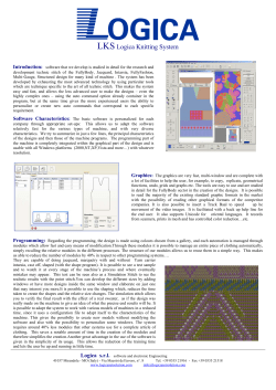


© Copyright 2026