
758-917 WAGO-I/O-SYSTEM 758 Manual WLAN ETHERNET Gateway 5 GHz
Manual WAGO-I/O-SYSTEM 758 WLAN ETHERNET Gateway 5 GHz 758-917 Version 1.0.1, applicable from HW/SW Version 01/01 2 WAGO-I/O-SYSTEM 758 758-917 WLAN ETHERNET Gateway 5 GHz © 2014 by WAGO Kontakttechnik GmbH & Co. KG All rights reserved. WAGO Kontakttechnik GmbH & Co. KG Hansastraße 27 D-32423 Minden Phone: Fax: +49 (0) 571/8 87 – 0 +49 (0) 571/8 87 – 1 69 E-Mail: [email protected] Web: http://www.wago.com Technical Support Phone: Fax: +49 (0) 571/8 87 – 5 55 +49 (0) 571/8 87 – 85 55 E-Mail: [email protected] Every conceivable measure has been taken to ensure the accuracy and completeness of this documentation. However, as errors can never be fully excluded, we always appreciate any information or suggestions for improving the documentation. E-Mail: [email protected] We wish to point out that the software and hardware terms as well as the trademarks of companies used and/or mentioned in the present manual are generally protected by trademark or patent. Manual Version 1.0.1, applicable from HW/SW Version 01/01 WAGO-I/O-SYSTEM 758 758-917 WLAN ETHERNET Gateway 5 GHz Table of Contents 3 Table of Contents 1 1.1 1.2 1.3 1.4 1.5 1.6 Notes about this Documentation ................................................................. 5 Validity of this Documentation ................................................................. 5 Revision History........................................................................................ 5 Copyright................................................................................................... 5 Symbols ..................................................................................................... 6 Number Notation ....................................................................................... 8 Font Conventions ...................................................................................... 8 2 Important Notes ........................................................................................... 9 2.1 Legal Bases ............................................................................................... 9 2.1.1 Subject to Changes ............................................................................... 9 2.1.2 Personnel Qualification ........................................................................ 9 2.1.3 Use in Compliance with Underlying Provisions .................................. 9 2.2 Special Use Conditions for ETHERNET Devices .................................. 10 2.3 Technical Condition of Specified Devices .............................................. 10 2.4 Storage, Assembly and Transport ........................................................... 10 2.5 Safety Advice (Precautions) .................................................................... 11 3 Device Description ..................................................................................... 13 3.1 General Description ................................................................................ 13 3.1.1 WLAN Operating Modes ................................................................... 13 3.1.2 LAN Connection Types ...................................................................... 15 3.1.2.1 Bridge Connection ......................................................................... 15 3.1.2.2 Direct Connection .......................................................................... 15 3.2 View ........................................................................................................ 16 3.3 Labeling................................................................................................... 17 3.4 Connectors............................................................................................... 18 3.4.1 Pin Assignment for Power Supply ..................................................... 18 3.4.2 Pin Assignment for System Connection ............................................. 18 3.4.3 Antenna............................................................................................... 19 3.5 Display Elements .................................................................................... 21 3.6 Operating Elements ................................................................................. 23 3.7 Technical Data ........................................................................................ 24 3.7.1 General Device Data........................................................................... 24 3.7.2 ETHERNET Interface ........................................................................ 25 3.7.3 Radio Interface ................................................................................... 25 3.7.4 Supply ................................................................................................. 25 3.8 Approvals ................................................................................................ 26 4 4.1 4.2 Mounting..................................................................................................... 27 Selecting the Installation Location .......................................................... 27 Fixing ...................................................................................................... 29 5 5.1 Connect Devices ......................................................................................... 30 Connection .............................................................................................. 30 6 Commissioning ........................................................................................... 31 7 7.1 Configuration ............................................................................................. 32 Default Settings ....................................................................................... 32 Manual Version 1.0.1, applicable from HW/SW Version 01/01 4 Table of Contents WAGO-I/O-SYSTEM 758 758-917 WLAN ETHERNET Gateway 5 GHz 7.2 Configuration Using the Mode Membrane Button ................................. 33 7.2.1 Selection and Activation of an Autoconfiguration Procedure ............ 33 7.2.2 Overview of Autoconfiguration Procedures ....................................... 36 7.3 Configuration Using the External Trigger Input ..................................... 38 7.4 Configuration using the Web-based Management System (WBM) ....... 39 7.4.1 Accessing the Web-based Management System ................................ 39 7.4.2 “Access Management” Section .......................................................... 42 7.4.3 “System Overview” Section ............................................................... 42 7.4.4 “Network Settings” Section................................................................ 43 7.4.5 “Wireless LAN Settings” Section ...................................................... 45 7.4.6 “Miscellaneous” Section .................................................................... 48 7.4.6.1 Execution of AT Commands ......................................................... 49 8 Appendix ..................................................................................................... 51 8.1 Sample Configurations ............................................................................ 51 8.1.1 Preparation .......................................................................................... 51 8.1.2 Bridge Connection, without Access Point .......................................... 51 8.1.2.1 Configuration of the 1st WEG Using the Mode Membrane Button52 8.1.2.2 Configuration of the 2nd WEG Using the Mode Membrane Button53 8.1.2.3 Configuration of the WEGs Using WBM ..................................... 53 8.1.3 Bridge Connection, with Access Point ............................................... 55 8.1.3.1 WEGs and Access Point wirelessly connected .............................. 55 8.1.3.2 Cable Connection between WEG and Access Point...................... 58 8.1.4 Direct Connection, without Access Point ........................................... 60 8.1.5 Direct Connection, with Access Point ................................................ 62 8.2 Time Response ........................................................................................ 64 8.3 Data Rate ................................................................................................. 66 8.4 Coexistence ............................................................................................. 67 8.4.1 Basics .................................................................................................. 67 8.4.2 Optimizing the Device Configuration ................................................ 68 8.5 Range in Open Field................................................................................ 69 8.6 Data Security for Radio Transmission .................................................... 71 List of Figures ...................................................................................................... 72 List of Tables ........................................................................................................ 73 Manual Version 1.0.1, applicable from HW/SW Version 01/01 WAGO-I/O-SYSTEM 758 758-917 WLAN ETHERNET Gateway 5 GHz 1 Notes about this Documentation Notes about this Documentation Keep this documentation! The operating instructions are part of the product and shall be kept for the entire lifetime of the product. They shall be transferred to each subsequent user of the product. Care must also be taken to ensure that any supplement to these instructions are included, if applicable. 1.1 Validity of this Documentation This documentation is only applicable to the WLAN ETHERNET Gateway 5 GHz 758-917. The device shall only be installed and operated according to the instructions in this manual. 1.2 Revision History Table 1: Revision History Document Device version Revision version Hardware Firmware 1.0.0 01 01 1.0.1 01 01 Editorial changes. 1.3 Copyright This Manual, including all figures and illustrations, is copyright-protected. Any further use of this Manual by third parties that violate pertinent copyright provisions is prohibited. Reproduction, translation, electronic and phototechnical filing/archiving (e.g., photocopying) as well as any amendments require the written consent of WAGO Kontakttechnik GmbH & Co. KG, Minden, Germany. Non-observance will involve the right to assert damage claims. Manual Version 1.0.1, applicable from HW/SW Version 01/01 5 6 1.4 Notes about this Documentation WAGO-I/O-SYSTEM 758 758-917 WLAN ETHERNET Gateway 5 GHz Symbols Personal Injury! Indicates a high-risk, imminently hazardous situation which, if not avoided, will result in death or serious injury. Personal Injury Caused by Electric Current! Indicates a high-risk, imminently hazardous situation which, if not avoided, will result in death or serious injury. Personal Injury! Indicates a moderate-risk, potentially hazardous situation which, if not avoided, could result in death or serious injury. Personal Injury! Indicates a low-risk, potentially hazardous situation which, if not avoided, may result in minor or moderate injury. Damage to Property! Indicates a potentially hazardous situation which, if not avoided, may result in damage to property. Damage to Property Caused by Electrostatic Discharge (ESD)! Indicates a potentially hazardous situation which, if not avoided, may result in damage to property. Important Note! Indicates a potential malfunction which, if not avoided, however, will not result in damage to property. Manual Version 1.0.1, applicable from HW/SW Version 01/01 WAGO-I/O-SYSTEM 758 758-917 WLAN ETHERNET Gateway 5 GHz Notes about this Documentation Additional Information: Refers to additional information which is not an integral part of this documentation (e.g., the Internet). Manual Version 1.0.1, applicable from HW/SW Version 01/01 7 8 1.5 Notes about this Documentation Number Notation Table 2: Number notation Number code Decimal Hexadecimal Binary 1.6 WAGO-I/O-SYSTEM 758 758-917 WLAN ETHERNET Gateway 5 GHz Example 100 0x64 '100' '0110.0100' Note Normal notation C notation In quotation marks, nibble separated with dots (.) Font Conventions Table 3: Font conventions Font type italic Menu > Input “Value” [Button] [Key] Indicates Names of paths and data files are marked in italic-type. e.g.: C:\Programme\WAGO-I/O-CHECK Menu items are marked in bold letters. e.g.: Save A greater-than sign between two names means the selection of a menu item from a menu. e.g.: File > New Designation of input or optional fields are marked in bold letters, e.g.: Start of measurement range Input or selective values are marked in inverted commas. e.g.: Enter the value “4 mA” under Start of measurement range. Pushbuttons in dialog boxes are marked with bold letters in square brackets. e.g.: [Input] Keys are marked with bold letters in square brackets. e.g.: [F5] Manual Version 1.0.1, applicable from HW/SW Version 01/01 WAGO-I/O-SYSTEM 758 758-917 WLAN ETHERNET Gateway 5 GHz 2 Important Notes 9 Important Notes This section includes an overall summary of the most important safety requirements and notes that are mentioned in each individual section. To protect your health and prevent damage to devices as well, it is imperative to read and carefully follow the safety guidelines. 2.1 Legal Bases 2.1.1 Subject to Changes WAGO Kontakttechnik GmbH & Co. KG reserves the right to provide for any alterations or modifications that serve to increase the efficiency of technical progress. WAGO Kontakttechnik GmbH & Co. KG owns all rights arising from the granting of patents or from the legal protection of utility patents. Third-party products are always mentioned without any reference to patent rights. Thus, the existence of such rights cannot be excluded. 2.1.2 Personnel Qualification All sequences implemented on the device may only be carried out by electrical specialists with sufficient knowledge in installation and handling of electrical equipment. The electrical specialists must also be familiar with the current standards and guidelines valid for the device. 2.1.3 Use in Compliance with Underlying Provisions The device is used for wireless transmission of ETHERNET data packets per IEEE 802.3. A radio link must be set up for this to another device, for example a second WLAN ETHERNET Gateway 5 GHz 758-917, that also supports the applicable radio protocol. The device has been developed for use in an environment that meets the IP65 protection class criteria. This specifies dust-tightness and protection against water jets (nozzle) from any angle. Operation in hazardous areas is prohibited. Manual Version 1.0.1, applicable from HW/SW Version 01/01 10 2.2 Important Notes WAGO-I/O-SYSTEM 758 758-917 WLAN ETHERNET Gateway 5 GHz Special Use Conditions for ETHERNET Devices If not otherwise specified, ETHERNET devices are intended for use on local networks. Please note the following when using ETHERNET devices in your system: 2.3 • Do not connect control components and control networks to an open network such as the Internet or an office network. WAGO recommends putting control components and control networks behind a firewall. • Limit physical and electronic access to all automation components to authorized personnel only. • Change the default passwords before first use! This will reduce the risk of unauthorized access to your system. • Regularly change the passwords used! This will reduce the risk of unauthorized access to your system. • If remote access to control components and control networks is required, use a Virtual Private Network (VPN). • Regularly perform threat analyses. You can check whether the measures taken meet your security requirements. • Use “defense-in-depth” mechanisms in your system's security configuration to restrict the access to and control of individual products and networks. Technical Condition of Specified Devices The components to be supplied Ex Works, are equipped with hardware and software configurations, which meet the individual application requirements. WAGO Kontakttechnik GmbH & Co. KG will be exempted from any liability in case of changes in hardware or software as well as to non-compliant usage of components. Please send your request for modified and new hardware or software configurations directly to WAGO Kontakttechnik GmbH & Co. KG. 2.4 Storage, Assembly and Transport Whenever possible, the components are to be stored in their original packaging. Likewise, the original packaging provides optimal protection during transport. When assembling or repacking the components, the contacts must not be soiled or damaged. The components must be stored and transported in appropriate containers/packaging. Thereby, the ESD information is to be regarded. Manual Version 1.0.1, applicable from HW/SW Version 01/01 WAGO-I/O-SYSTEM 758 758-917 WLAN ETHERNET Gateway 5 GHz 2.5 Important Notes 11 Safety Advice (Precautions) For installing and operating purposes of the relevant device to your system the following safety precautions shall be observed: Always use voltage sources with current limitation/safety extra-low voltage! Only use power supply sources based on IEC/EN60950 Section 2.5 “Power sources with limited output” with the device. The output of the external power supply must be short-circuit protected. The output voltage of the external power supply shall not exceed 30 VDC. Do not use device in hazardous environments! The device is not designed for use in hazardous areas. Maintenance/Repair only by authorized specialists! The device contains no parts that can be serviced by users. Always have all service, reconfiguration, maintenance or repair work performed by specialists authorized by WAGO. Do not work on components while energized! All power sources to the device shall be switched off prior to performing any installation, repair or maintenance work. Keep a distance of 20 cm to persons! Install the device such that it is located at least 20 cm away from all persons during operation. Replace defective or damaged devices! Replace defective or damaged device (e.g., in the event of deformed contacts), since the long-term functionality of fieldbus station involved can no longer be ensured. Manual Version 1.0.1, applicable from HW/SW Version 01/01 12 Important Notes WAGO-I/O-SYSTEM 758 758-917 WLAN ETHERNET Gateway 5 GHz Protect the components against materials having seeping and insulating properties! The components are not resistant to materials having seeping and insulating properties such as: aerosols, silicones and triglycerides (found in some hand creams). If you cannot exclude that such materials will appear in the component environment, then install the components in an enclosure being resistant to the above-mentioned materials. Clean tools and materials are imperative for handling devices/modules. Cleaning only with permitted materials! Clean soiled contacts using oil-free compressed air or with ethyl alcohol and leather cloths. Avoid electrostatic discharge! The devices are equipped with electronic components that you may destroy by electrostatic discharge when you touch. Pay attention while handling the devices to good grounding of the environment (persons, job and packing). Device uses radio waves! Never use the device in areas where operation of radio equipment is prohibited. Do not open the enclosure! Never open the enclosure. Opening of the enclosure will nullify the guarantee, legal warranty and authorization for use. Manual Version 1.0.1, applicable from HW/SW Version 01/01 WAGO-I/O-SYSTEM 758 758-917 WLAN ETHERNET Gateway 5 GHz 3 Device Description 3.1 General Description Device Description 13 As a wireless ETHERNET gateway (WEG), the 758-917 device makes it possible to integrate conventional ETHERNET devices in a wireless network. For this purpose, the device has a wired ETHERNET interface and another interface for radio communication. The device uses the integrated radio technology to transmit the data received on the ETHERNET interface. Conversely, the device uses the ETHERNET interface to send data received on the radio interface. As data transmission of ETHERNET packets occurs with a transparent protocol on Layer 2 of the OSI reference model, this provides for easy integration of all Ethernetbased fieldbuses, such as MODBUS/TCP, ETHERNET/IP, PROFINET or PROFISAFE. In combination with another function-related device, e.g., another WEG or Access Point (AP) of the same radio technology, the WEG can serve as a wireless replacement for ETHERNET cables. The WEG permits particularly robust, realtime radio connections over long distances. A suitable configuration can also prevent any degradation to other radio networks. Figure 1: Wireless transmission between two WEGs An innovative operator control concept enables easy initiation of automatic configuration processes using a Mode membrane key on the device. This can be used to configure a substitute cable link between two WEGs in only a few seconds, without using additional aids or hardware / software. In addition to operation using the Mode membrane key and the 7 LED status indicators, access to other status information and advanced device functions of the WEG is also possible via a Web-based Management System (WBM). Depending on the application, the unit can be operated in various modes. 3.1.1 WLAN Operating Modes WLAN distinguishes between two fundamentally different network operating modes: Infrastructure mode and ad-hoc mode. Manual Version 1.0.1, applicable from HW/SW Version 01/01 14 Device Description WAGO-I/O-SYSTEM 758 758-917 WLAN ETHERNET Gateway 5 GHz Figure 2: Infrastructure mode In infrastructure mode, a distinction is made between two roles for devices in the network. One of the WLAN devices must act as an access point and centrally manage the network while all other WLAN devices act as clients. Figure 3: Ad-hoc mode In ad-hoc mode, the attached WLAN devices manage the network peripherally. Due to the higher administrative effort, only lower data rates and limited security mechanisms are available in contrast to the infrastructure mode. The WEG can establish a connection with WLAN networks of both operating modes, but cannot function as an access point itself. If an access point is available Manual Version 1.0.1, applicable from HW/SW Version 01/01 WAGO-I/O-SYSTEM 758 758-917 WLAN ETHERNET Gateway 5 GHz Device Description 15 and the WEGs can be configured via Web-based Management, the preferred method of operation for the WLAN is in infrastructure mode. This permits higher data rates and the use of better security mechanisms. 3.1.2 LAN Connection Types Independent of the selected WLAN operating mode, the WEG can be configured for two different LAN connection types: Bridge connection and direct connection. 3.1.2.1 Bridge Connection Similar to using an ETHERNET switch, the bridge connection makes it possible to connect two ETHERNET segments. To this end, exactly two WEGs must be configured in the network, so that a connection transparent for LAN devices (a bridge) is created between them. In this way, connected WEGs are functionally comparable to two ports of an ETHERNET switch to which other ETHERNET hubs or switches can also be connected. Bridge connection between two ETHERNET segments only! A WEG can use a bridge connection to connect exactly one locally connected ETHERNET segment with exactly one ETHERNET segment connected to another WEG. It is not possible, for example, to connect three ETHERNET segments in this manner. DHCP is not supported with bridge connections! If a bridge connection is established, the IP addresses of the WEGs must be static. Automatic reference of IP addresses via DHCP is not supported for this connection type. 3.1.2.2 Direct Connection In a direct connection, a WEG can be used as a wireless adapter for exactly one wireless ETHERNET device. The WEG acts as a wireless extension of the wired network interface of this reference device by cloning its ETHERNET MAC address. Therefore, the reference device must be connected to the associated WEG directly. If an ETHERNET segment is connected to several instead of a single ETHERNET device, only the reference device can use the WEG as a wireless adapter without restriction. Manual Version 1.0.1, applicable from HW/SW Version 01/01 16 3.2 Device Description WAGO-I/O-SYSTEM 758 758-917 WLAN ETHERNET Gateway 5 GHz View Figure 4: View Table 4: Legend for the “View” figure No. 1 2 3 4 5 6 7 8 Description Status and diagnosis LEDs (front) Internal circular polarized directional antenna 5 dB Fixing hole 1 LEDs for link quality indication (bottom), configuration and status indication Mode membrane key for configuration Network connection, M12 socket on device Power supply, M12 connector on device Fixing hole 2 Details see Section: “Display Elements” “Connectors” “Mounting” “Display Elements” “Operating Elements” “Connectors” “Connectors” “Mounting” Manual Version 1.0.1, applicable from HW/SW Version 01/01 WAGO-I/O-SYSTEM 758 758-917 WLAN ETHERNET Gateway 5 GHz 3.3 Device Description 17 Labeling The status indicators for (POWER, (((.))), LAN) are marked on the front of the device. Figure 5: Marking on front of device The connections (Power, LAN), link quality and configuration button (Mode) are marked on the bottom of the device. Figure 6: Marking on bottom The device MAC address is included with other device data on the nameplate on the back or side of the device. Figure 7: Nameplate on back/side Manual Version 1.0.1, applicable from HW/SW Version 01/01 18 Device Description 3.4 WAGO-I/O-SYSTEM 758 758-917 WLAN ETHERNET Gateway 5 GHz Connectors The device is equipped with two connections at the bottom: Figure 8: Connections at bottom of device Table 5: Legend for the “Connections at bottom of device” figure No. Description 1 Power supply and trigger input (“Power”) 2 Network connection (“LAN”) 3.4.1 Pin Assignment for Power Supply Power is supplied to the device via a 5-pole, A-coded M12 connector. Table 6: Power supply, M12 Connector on Device Pin 1 2 3 4 5 3.4.2 Pin assignment Vin + (9 V … 30 VDC) Trigger input ground Vin Ground (0 V) Trigger-input + (9 V … 30 VDC) Not in use Pin Assignment for System Connection The device is connected to the ETHERNET network via a 4-pole, D-coded socket and supports autonegotiation for 10/100 Mbit and the duplex mode. Table 7: System connection, M12 Socket on Device Pin Pin assignment 1 Transmit + 2 Receive + 3 Transmit - 4 Receive - Manual Version 1.0.1, applicable from HW/SW Version 01/01 WAGO-I/O-SYSTEM 758 758-917 WLAN ETHERNET Gateway 5 GHz 3.4.3 Device Description 19 Antenna The device is equipped with an internal antenna. Good reception conditions exist when the front of the device is oriented centered to the remote device with which the radio link is to be established. Figure 9: Aligning the device The alignment characteristic for the internal antenna is primarily relevant for links in the open field and over long distances. When operating the device at short distances, inside buildings or without line-of-sight links structural conditions are the decisive factor for good reception. As the device comes equipped with a circular polarized antenna, rotation of the device around the link axis between the local and remote device does not have any adverse impact on link quality. The directional alignment (antenna) diagrams for the antenna are given in the following figures for a frequency of 5.25 GHz. Manual Version 1.0.1, applicable from HW/SW Version 01/01 20 Device Description WAGO-I/O-SYSTEM 758 758-917 WLAN ETHERNET Gateway 5 GHz Figure 10: Antenna diagram 5.25 GHz – longitudinal axis The diagram above illustrates the two-dimensional top view of the electromagnetic field of the antenna, with the antenna being the center point. At a beam angle of around 60° the antenna provides excellent reception levels; reception continues to be good up to an angle of 90°, whereas reception markedly deteriorates at beam angles of 110° and greater. Figure 11: Antenna diagram 5.25 GHz – transverse axis The diagram above shows the side view of the antenna's electromagnetic field. Manual Version 1.0.1, applicable from HW/SW Version 01/01 WAGO-I/O-SYSTEM 758 758-917 WLAN ETHERNET Gateway 5 GHz 3.5 Device Description 21 Display Elements The current device status is indicated by the three LEDs on the front of the WEG. Four other LEDs at the bottom of the device indicate the link quality, or the selected autoconfiguration procedure. Figure 12: Display elements Table 8: Legend for the “Display elements” figure Nr. Designation * Color 1 Power green 2 ((( . ))) blue purple red 3 LAN 4 Link Quality* Status On Off Blue Blue flashing Purple Red Off On yellow Blinking Off A on A+B on green A+B+C on A on A+B on Meaning Device ready for operation Device not ready for operation Wireless link active Data transmission Setting up link to other radio device Error No wireless link available ETHERNET link available ETHERNET communication active No ETHERNET link available Acceptable link quality Good link quality Optimal link quality Acceptable link quality Good link quality Status signals are also indicated via LEDs A to D during configuration. In this case, the indicators will differ from the status information given here, see Section “Configuration using the Mode membrane button”. Observe the operating mode! The indicators for wireless and ETHERNET link are only valid when the power LED signals “Device ready for operation”. In special modes, such as device initialization or firmware update, the LEDs mentioned previously may respond differently than described above. Manual Version 1.0.1, applicable from HW/SW Version 01/01 22 Device Description WAGO-I/O-SYSTEM 758 758-917 WLAN ETHERNET Gateway 5 GHz Display of the link quality in conjunction with access point only! LEDs A to D are only available for visualization of the link quality when the WEG is connected to an access point (infrastructure mode). In an ad-hoc network, this status indication is not available. Manual Version 1.0.1, applicable from HW/SW Version 01/01 WAGO-I/O-SYSTEM 758 758-917 WLAN ETHERNET Gateway 5 GHz 3.6 Device Description 23 Operating Elements The “Mode” membrane button is located at the bottom of the device. This button is used to initiate certain autoconfiguration procedures. LEDs A to D indicate which procedure is active. For more information about this refer to the Section “Configuration using the Mode membrane button”. Figure 13: Operating element Table 5: Legend for the “Operating element” figure No. 1 Description Mode membrane button Manual Version 1.0.1, applicable from HW/SW Version 01/01 24 Device Description 3.7 Technical Data 3.7.1 General Device Data WAGO-I/O-SYSTEM 758 758-917 WLAN ETHERNET Gateway 5 GHz Table 9: Technical Data – General Device Data Function Dimensions (mm) WxHxD Weight Ports Operating temperature Storage temperature Degree of protection Relative humidity (without condensation) Connection to PE Fitting position Free from silicone RoHS-compliant Configuration Immunity to interference Emission of interference Mechanical stability Wireless ETHERNET Gateway (WEG) 66 x 91 x 36 120 g Power connector: M12 plug, A-coded ETHERNET connector: M12 socket, D-coded -30 °C ... + 65 °C -40 °C ... + 85 °C IP65 95 % Not required On a level mounting surface Yes Yes Via Web-based Management System or using the Mode membrane button Static discharge based on EN 61000-4-2: Contact discharge ± 6 kV Air discharge ± 8 kV Electromagnetic fields based on IEC61000-4-3: 10 V/m, Criterion A Mains borne disturbance based on IEC 61000-4-6: 10 V RMS, Criterion A Rapid transients (burst) based on IEC 61000-4-4: Data interface: 1 kV Power supply: 2 kV Surge voltage based on IEC 61000-4-5: Data interface: ± 1 kV Power supply: ± 0.5 kV per EN 55022 Class B (residential areas) Shock test based on IEC 60068-2-27 Operation 25 g, duration 11 ms Storage/Transport 50 g, duration 11 ms Vibration test based on IEC 60068-2-6 Operation 5 g, 10-150 Hz, Criterion 3 Free fall based on IEC 60068-2-32 1m Manual Version 1.0.1, applicable from HW/SW Version 01/01 WAGO-I/O-SYSTEM 758 758-917 WLAN ETHERNET Gateway 5 GHz 3.7.2 Device Description 25 ETHERNET Interface Table 10: Technical Data – ETHERNET Interface Number of inputs Medium Transmission rate Default IP address Default subnet mask 3.7.3 1 Via M12, twisted pair wire, wire cross section 0.14 mm² … 0.22 mm² 10/100 MBit/s, Autonegotiation 192.168.1.99 255.255.255.0 Radio Interface Table 11: Technical Data – Radio Interface Protocol Antenna Transmission range Topology Connection type 3.7.4 IEEE 802.11 a/n, max. 58.5 MBit/s Internal directional antenna (non-exchangeable) Up to 400 m (open field) Infrastructure, Ad-hoc Client Supply Table 12: Technical Data – Power Supply Power supply connection Nominal Voltage Voltage range, permissible Current consumption, typical Current consumption, maximum Via M12, max. wire cross section 2.5 mm² 24 VDC (SELV) 9 V … 30 VDC 80 mA at 24 VDC 120 mA at 24 V Manual Version 1.0.1, applicable from HW/SW Version 01/01 26 3.8 Device Description WAGO-I/O-SYSTEM 758 758-917 WLAN ETHERNET Gateway 5 GHz Approvals Conformity Marking IC „Industry Canada“ IC: 5325A-0941 FCC “Federal Communications Commission” FCC ID: PVH0941 / CFR 47 Part 15, ETS 300328 This device complies with Part 15 of the FCC Rules. Operation is subject to the following two conditions: (1) this device may not cause harmful interference, and (2) this device must accept any interference received, including interference that may cause undesired operation. With the exception of Andorra, Bulgaria, France and Latvia, the device may be used without restrictions in all European countries and in Switzerland, the USA and Canada. The device may be used inside buildings in Bulgaria. In France, the transmitting power must be limited to 10 dBm when used outside of buildings. In Norway the device may not be used with a radius of 20 km of the town center of Ny-Âlesund (Spitzbergen). Manual Version 1.0.1, applicable from HW/SW Version 01/01 WAGO-I/O-SYSTEM 758 758-917 WLAN ETHERNET Gateway 5 GHz 4 Mounting 4.1 Selecting the Installation Location Mounting 27 In order to use all the functions of the WEG, a radio link must be established to a device having similar functions, for example a second WEG of the same type. If the two devices are relatively close to one another, that is, if the distance between them is considerably less than the potential range, the installation location and device alignment will have comparatively little impact on the radio link. If you wish to set up and maintain a radio link over the longest distance possible, however, certain requirements regarding the installation of the device and the ambient conditions must be fulfilled. The distance between devices may not be too great. The maximum range can only be effective under optimal conditions. A lack of line-of-sight link, or misalignment of the devices will result in reduced range. For a line-of-sight link, install the devices such that the antennas are aligned toward one another, i.e., the marked front side of the devices face one another (see also the figure and the antenna diagrams in the section “Connectors” > “Antenna”). If there is no line-of-sight link, but both devices have an unobstructed view of the same metallic or concrete surface (such as a building ceiling), a good radio link can be ensured through reflection. If there is neither a line-of-sight link, nor a surface to use for reflection, for example between devices in different rooms, align the devices as for a line-ofsight link. The magnitude of the reduction in range for the devices in this case depends on the amount of material, e.g., brick walls, that the radio waves must pass through. In some circumstances, it may not be possible for the radio waves to penetrate certain obstacles, such as fire protection walls, at all. Manual Version 1.0.1, applicable from HW/SW Version 01/01 28 Mounting WAGO-I/O-SYSTEM 758 758-917 WLAN ETHERNET Gateway 5 GHz Table 13: Selection of Installation Location Ambient Conditions, Installation Location Radio link possible? Distance between devices is more than 400 m. Line-of-sight link between devices that are about 200 m apart. Devices have been optimally installed and configured. Two plaster or brick walls are located between the devices; distance between devices is around 30 m. No Yes Yes. Links are also possible without line of sight, but the range is substantially reduced, depending on the obstacle (e.g., a wall). A fire protection wall or a steel-reinforced No. Reinforced concrete and concrete ceiling is located between the devices. other similar materials cannot be penetrated by radio waves when they are too thick. The devices are located less than 50 m apart in a Possible. Building ceilings or plant building, with the line of sight being other metallic or steelobstructed by numerous machines or vehicles. reinforced large objects may permit an indirect link by reflecting the radio waves. Manual Version 1.0.1, applicable from HW/SW Version 01/01 WAGO-I/O-SYSTEM 758 758-917 WLAN ETHERNET Gateway 5 GHz 4.2 Mounting 29 Fixing Always maintain a minimum distance of 50 cm between two WEGs! Always maintain a distance of at least 50 cm between WEGs when installing them. Radio link quality can be degraded on failure to maintain this distance. Do not install antenna directly in front of metallic surfaces! The front of the WEG, and hence the internal antenna, shall not be located directly in front of metallic surfaces, as this can permanently degrade the radio capabilities of the antenna. Use the drilled holes (see drawing below), for example, and the two M3 screws to attach the WEG to any flat, level surface. Figure 14: Drilled holes for attaching the WEG Manual Version 1.0.1, applicable from HW/SW Version 01/01 30 Connect Devices 5 Connect Devices 5.1 Connection WAGO-I/O-SYSTEM 758 758-917 WLAN ETHERNET Gateway 5 GHz Before the device can be used, all cable connections must be established. Ensure that wires are not live! Power supply: Do not switch on the power supply until the device has been properly connected. LAN: Improperly routed ETHERNET cables can carry dangerous overvoltage. Always ensure that these cables have been laid properly before connecting the device to the network. 1. Use a suitable cable, such as WAGO Item 756-1203/060-050, to connect the WEG to your network or ETHERNET terminal. 2. Use a suitable cable, such as WAGO Item 756-3101/040-020, to connect the WEG to the external power supply unit. Figure 15: Connecting the WEG Manual Version 1.0.1, applicable from HW/SW Version 01/01 WAGO-I/O-SYSTEM 758 758-917 WLAN ETHERNET Gateway 5 GHz 6 Commissioning Commissioning The device is not equipped with a power switch, meaning it is put into operation simply by applying power. Use the correct supply voltage! The output of the power supply unit must provide 24 VDC with a maximum current flow of 200 mA. Switch on the external power supply unit to put the device into operation. Manual Version 1.0.1, applicable from HW/SW Version 01/01 31 32 7 Configuration WAGO-I/O-SYSTEM 758 758-917 WLAN ETHERNET Gateway 5 GHz Configuration After you have connected the WEG you can configure it in one of two ways: • • using the Mode membrane button and by activating certain modes by making settings via the Web-based Management System (WBM) The various types of configuration are described in the following sections. If the device has already been configured and you are not familiar with the current configuration, we recommend resetting the device to its factory default settings before making any further configuration settings. This can be done using the Mode membrane button. 7.1 Default Settings The following settings are active on initial startup of the WEG: Tabelle 14: Default Settings Group Access Management Network Settings Network Settings Network Settings Network Settings Wireless LAN Settings Wireless LAN Settings Wireless LAN Settings Wireless LAN Settings Wireless LAN Settings Wireless LAN Settings Wireless LAN Settings Wireless LAN Settings Wireless LAN Settings Parameter Password IP Address Subnet Mask Default Gateway IP Assignment Network Name (SSID) Operating Mode Channel Channel List Data Rate Transmit Power Security Mode Mode WLAN MAC Address Miscellaneous S Register 1216 SMART Modes Action triggered by event TRIGGER_PUSH Action triggered by “0” event TRIGGER_HOLD S Register 1217 Default value “wago” “192.168.1.99” “255.255.255.0” “192.168.1.99” “Static” (empty) “Infrastructure” “0 (Auto)” “36-64, 100-140” “0 (Auto)” “+17 dBm” “None” “Multi-Client” (same as parameter ETHERNET MAC Address) “4” “0” You can always restore the factory default settings at any time using the Mode membrane button (see following section). This can be useful, for example, if you have forgotten the IP address or the device AT password. Manual Version 1.0.1, applicable from HW/SW Version 01/01 WAGO-I/O-SYSTEM 758 758-917 WLAN ETHERNET Gateway 5 GHz 7.2 Configuration 33 Configuration Using the Mode Membrane Button The quickest and easiest method for configuring the device is using the Mode membrane button located at the bottom of the device. LEDs A to D indicate the status during configuration, based on the active operating mode. By repeatedly pressing the Mode membrane button you can select and start an autoconfiguration procedure in the device that then automatically carries out the device configuration for the required scenario. Figure 16: Mode membrane button and status LEDs 7.2.1 Selection and Activation of an Autoconfiguration Procedure General procedure: 1. Switch off the power supply to the WEG and then re-activate power supply to the device. The Power LED lights up. 2. Within the first 5 seconds after applying power, press the Mode membrane button to switch to the operating mode “Configuration selection”. LED A lights up and the operating mode “Configuration selection” is active. If this is not the case, repeat steps 1 and 2. 3. Select the autoconfiguration procedure: Select the required autoconfiguration procedure by pressing the Mode membrane button until the appropriate combination of LEDs lights up (see previous section “Overview of Autoconfiguration Procedures”). If you have switched through all the operating modes in order, you can return to the first option in the order by pressing the button again. Manual Version 1.0.1, applicable from HW/SW Version 01/01 34 Configuration WAGO-I/O-SYSTEM 758 758-917 WLAN ETHERNET Gateway 5 GHz Configuration is halted if the Mode membrane button is not pressed for 20 s! The mode “Configuration selection” is de-activated automatically if you do not press the Mode membrane button for selecting the autoconfiguration procedure. The WEG will then start up using the previous settings. 4. Activate autoconfiguration procedure: To execute the selected autoconfiguration procedure press the Mode membrane button again and hold it in for at least 2 seconds until the LED indicators A-D or the Power LED change. The device performs a restart as soon as the procedure has been completed successfully or canceled. The behavior of the device up to this restart is based on the active autoconfiguration procedure: Procedures 2, 3: Other procedures: The device carries out the changes to the configuration and ends the procedure directly after this. This only takes a few seconds. The LEDs A-D corresponding to the procedure will flash until the procedure is concluded. All of these procedures can also be manually terminated prematurely by pressing the Mode membrane button again, or by briefly disconnecting the power supply from the device. These procedures end automatically on successful configuration of a link, or after a timeout of 5 minutes. The LEDs return to their normal status on conclusion of the autoconfiguration procedure. Manual Version 1.0.1, applicable from HW/SW Version 01/01 WAGO-I/O-SYSTEM 758 758-917 WLAN ETHERNET Gateway 5 GHz Configuration 35 Figure 17: Flow chart Enable de-activated WBM using the Mode membrane button! If autoconfiguration is conducted with PROFINET optimization, the device deactivates the Web-based Management System to provide short cycle times. Consequently, configuration can only be changed using the Mode membrane button. Reset the device to the factory default settings to enable access to the Webbased Management System again. Manual Version 1.0.1, applicable from HW/SW Version 01/01 36 Configuration 7.2.2 WAGO-I/O-SYSTEM 758 758-917 WLAN ETHERNET Gateway 5 GHz Overview of Autoconfiguration Procedures The following autoconfiguration procedures can be selected in the order given: Table 15: Autoconfiguration Procedures Press button Autoconfiguration Procedures 1 Automatically obtain temporary IP parameters The device attempts to obtain temporary IP parameters from a DHCP server. Parameters obtained in this manner are only valid until the next reboot. A 2 Reset device to factory default settings Restore all settings to the factory default settings. B 3 Reset IP parameters Restore the IP parameters to the factory default settings. All other settings are retained. 4 Wait for automatic configuration The device will wait for configuration by a different WEG that executes the Autoconfiguration procedure “Initiate automatic configuration”. Although the device is connectable, it will not initiate the setting up of a link. C Initiate automatic configuration The device automatically sets up a link to a different WEG that executes the Autoconfiguration procedure “Wait for automatic configuration”. When a connection has been established, both WEGs are automatically configured for a bridge connection. A+C Wait for automatic configuration, with PROFINET/PROFISAFE optimization The device will wait for configuration by a different WEG that executes the Autoconfiguration procedure “Initiate automatic configuration, with PROFINET-/PROFISAFE optimization”. Although the device is connectable, it will not initiate the setting up of a link. B+C 1x 2x 3x 4x 5 5x 6 6x 7 7x LED A B C D A+B Initiate automatic configuration, with PROFINET/PROFISAFE optimization The device automatically sets up a link to a different WEG that executes the Autoconfiguration procedure “Wait for A+B+C automatic configuration, with PROFINET-/PROFISAFE optimization”. When a connection has been established, both WEGs are automatically configured for a bridge connection and PROFINET/PROFISAFE optimization activated. On configuration using the Mode membrane button, only those parameters required for the particular autoconfiguration will be overwritten. You can use the Web-based Management to make changes to the settings not affected by the respective autoconfiguration. These changes also remain effective after a configuration using the Mode membrane button. Manual Version 1.0.1, applicable from HW/SW Version 01/01 WAGO-I/O-SYSTEM 758 758-917 WLAN ETHERNET Gateway 5 GHz Configuration 37 Autoconfiguration procedures 1 to 3 always become effective; procedures 2 and 3 change the device configuration immediately. Autoconfiguration procedures 4 to 7 only change the device configuration when a radio link has been successfully established. If the WEG loses power before the autoconfiguration has been completed, or if no other WEG can be contacted via the radio link within 5 minutes for automatic configuration, the device will retain its previous configuration settings when it is restarted. The following settings are overwritten in the course of the various autoconfiguration procedures: Table 16: Overwriting of Configuration Autoconfigurati Changes to Configuration on Successful Setup of Link on procedure The following settings are temporarily modified: 1 • Network Settings > IP-Address: “192.168.1.99” • Network Settings > Subnet Mask: “255.255.255.0” • Network Settings > Default Gateway: “192.168.1.99” • Network Settings > IP Assignment: “Static & DHCP Server” The saved configuration is restored after rebooting the device. All settings are changed. 2 • Network Settings > IP-Address: “192.168.1.99” 3 • Network Settings > Subnet Mask: “255.255.255.0” • Network Settings > Gateway: “192.168.1.99” • Network Settings > IP Assignment: “Static” • Network Settings > IP-Address: “192.168.1.99” 4 • Network Settings > Subnet Mask: “255.255.255.0” • Network Settings > Gateway: “192.168.1.99” • Network Settings > IP Assignment: “Static” • Wireless LAN Settings > Network Name (SSID): (as partnered device) • Wireless LAN Settings > Operating Mode: “Ad-Hoc” • Wireless LAN Settings > Security Mode: “WEP128” • Wireless LAN Settings > Passkey: (as partnered device) • Wireless LAN Settings > IP Address: “192.168.1.100” • Wireless LAN Settings > UDP Port: “7” • Network Settings > IP-Address: “192.168.1.100” 5 • Network Settings > Subnet Mask: “255.255.255.0” • Network Settings > Gateway: “192.168.1.99” • Network Settings > IP Assignment: “Static” • Wireless LAN Settings > Network Name (SSID): (as partnered device) • Wireless LAN Settings > Operating Mode: “Ad-Hoc” • Wireless LAN Settings > Security Mode: “WEP128” • Wireless LAN Settings > Passkey: (as partnered device) • Wireless LAN Settings > IP Address: “192.168.1.99” • Wireless LAN Settings > UDP Port: “7” As autoconfiguration procedure 4, but also: 6 • De-activate the Web-based Management System • Activate PROFINET optimization As autoconfiguration procedure 5, but also: 7 • De-activate the Web-based Management System • Activate PROFINET optimization Manual Version 1.0.1, applicable from HW/SW Version 01/01 38 7.3 Configuration WAGO-I/O-SYSTEM 758 758-917 WLAN ETHERNET Gateway 5 GHz Configuration Using the External Trigger Input The external trigger input can be used to signal the device of one of two events. Which process is triggered can be configured for each event (see Section “Configuration Using Web-based Management”). Before the trigger input can be used in this manner, the power supply to the trigger input must be switched off. • To signal the TRIGGER_PUSH event, apply a voltage to the trigger input for a period of less than 2 seconds. The signal is triggered when the power supply to the trigger input is switched off again. • To signal the TRIGGER_HOLD event, apply a voltage to the trigger input for a period of more than 2 seconds. The signal is triggered after approx. 2 seconds. Switch off the power supply to the trigger input again! The device ignores when the Mode Membrane button is pressed when the external trigger input has power. Therefore, always switch off the power supply to the trigger input after signaling TRIGGER_HOLD. Manual Version 1.0.1, applicable from HW/SW Version 01/01 WAGO-I/O-SYSTEM 758 758-917 WLAN ETHERNET Gateway 5 GHz 7.4 Configuration 39 Configuration using the Web-based Management System (WBM) A Web-based Management System (WBM) is available on an integrated Web server for configuring the WEG. You can go the WBM by entering the IP address of the device in the browser URL line. Device configuration is password protected. On initial commissioning, the device uses the static IP address and the default settings password (see section “Default Settings”). If you have forgotten the IP address or password you can reset the device to its factory default settings. The IP address of the PC used to access the WBM must be in the same subnet as the WEG. You may have to modify the IP configuration of the PC from which you are accessing the WBM before a link can be set up. If the PC is configured to get the IP address via DHCP automatically, you can connect the WEG and PC directly and temporarily activate the integrated DHCP server of the WEG via autoconfiguration procedure 1 (see section “Configuration Using the Mode Membrane Button”). 7.4.1 Accessing the Web-based Management System 1. To open the WBM, launch a Web browser (e.g., Microsoft Internet Explorer or Mozilla Firefox). 2. Enter the IP address of the WEG on the URL line and confirm by pressing [Enter]. For WBM access; check the IP/firewall settings and the connection! If you are not granted access to the WBM check the IP configuration for the PC from which you wish to access the WBM and the settings for the firewalls being used. Ensure that the WEG is properly connected and ready for operation and that the specified IP address is correct. Should you still not be able to set up a connection to the WBM after ruling out any error at the PC, or if you have forgotten the IP address of the WEG, reset the device to its factory default settings. When access has been made to the WBM the WEG will display an overview page showing status information and operating elements for changing the device configuration (see figure below). Manual Version 1.0.1, applicable from HW/SW Version 01/01 40 Configuration WAGO-I/O-SYSTEM 758 758-917 WLAN ETHERNET Gateway 5 GHz Figure 18: WBM main page before login Before taking any further steps you should log on to the system using a valid password: 3. Enter your password in the field System Overview > Password. 4. Send the password by clicking on [Login]. Manual Version 1.0.1, applicable from HW/SW Version 01/01 WAGO-I/O-SYSTEM 758 758-917 WLAN ETHERNET Gateway 5 GHz Figure 19: WBM main page after login Manual Version 1.0.1, applicable from HW/SW Version 01/01 Configuration 41 42 Configuration 7.4.2 WAGO-I/O-SYSTEM 758 758-917 WLAN ETHERNET Gateway 5 GHz “Access Management” Section You can enter or change the access password for protected device settings in this section. Figure 20: WBM section “Access Management” Change password 7.4.3 1. Enter the new password in the box New Password. 2. Enter the password again in the box Confirm Password. 3. Save the new password by clicking on [Change Password]. “System Overview” Section General information about the device and the device status is displayed in this section. Figure 21: WBM section “System Overview” Manual Version 1.0.1, applicable from HW/SW Version 01/01 WAGO-I/O-SYSTEM 758 758-917 WLAN ETHERNET Gateway 5 GHz Configuration 43 Table 17: WBM section “System Overview” Parameter General Firmware Wireless LAN Status Operating Mode MAC Address Status LAN Network IP Address Subnet Mask Default Gateway IP Assignment Ethernet MAC address LAN Status Value (example) Description (“2.3.5”) Display of the WEG firmware version (“Infrastructure”) Display of the network type (“00:12:F3:12:FE:76”) Display of the WLAN MAC address (“Not Connected”) Display of the WLAN link status (“192.168.1.99”) (“255.255.255.0”) (“192.168.1.99”) (“Static”) (“00:12:F3:0F:D6:1C”) (“Link up”) Display of the WEG IP address Display of the network mask Display of the gateway Display of the IP assignment method Display of the ETHERNET MAC address Display of the LAN link status Clicking the [Stop Automatic Update] or [Start Automatic Update] button respectively stops or starts automatic update of the information displayed. 7.4.4 “Network Settings” Section You can perform network configuration in this section. Figure 22: WBM section “Network Settings” Please note the interaction with other devices in the network! Changes to the network settings of a device can affect other devices in the same network. An improper configuration, e.g., duplicate assignment of the same IP address, can cause devices to not work as intended. Therefore, always make sure that the configuration is correct especially when devices are configured to function as DHCP servers. Manual Version 1.0.1, applicable from HW/SW Version 01/01 44 Configuration WAGO-I/O-SYSTEM 758 758-917 WLAN ETHERNET Gateway 5 GHz Table 18: WBM section “Network Settings > IP configuration” Parameter IP configuration IP address Subnet Mask Default gateway IP Assignment Value (example) Description (“192.168.1.99”) (“255.255.255.0”) (“192.168.1.99”) “Static” “DHCP Client” “Static & DHCP Server” “Static & DHCP Relay” “DHCP Client & DHCP Relay” Input IP address for WEG Input the network mask Input the standard gateway Deactivate DHCP, use static IP parameters Obtain IP parameters from DHCP server Use own static IP address and activate DHCP server Use own static IP address, forward DHCP queries to other devices Obtain IP parameters from DHCP server, forward DHCP queries to other devices Clicking the [Write Network Settings] button saves all settings of the Network Settings section. Use different IP addresses in network! To rule out any IP address conflicts, all devices must use different IP addresses. Reset IP parameters without changing settings! If you no longer know the IP address for your WEG you can reset the IP address for the WEG using the Mode membrane button without having to change other settings (see section “Configuration using the Mode Membrane Button” > “Overview of Autoconfiguration Procedures” > “3 – Resetting IP Parameters”). Manual Version 1.0.1, applicable from HW/SW Version 01/01 WAGO-I/O-SYSTEM 758 758-917 WLAN ETHERNET Gateway 5 GHz 7.4.5 Configuration 45 “Wireless LAN Settings” Section You can make changes in this section which affect the radio communications interface. Figure 23: WBM section “Wireless LAN Settings” Table 19: WBM section “Wireless LAN Settings > Network” Parameter Value Description (example) Wireless LAN Network Network Name (SSID) (“MySSID”) Input of the network SSID to which a connection is to be established. Clicking the [Scan for Networks] button scans for available WLAN networks. The SSIDs of any networks found appear in the dropdown menu above the button. Left-clicking on the SSID of any network found moves it from the list of the dropdown menu to the Network Name (SSID) field. Manual Version 1.0.1, applicable from HW/SW Version 01/01 46 Configuration WAGO-I/O-SYSTEM 758 758-917 WLAN ETHERNET Gateway 5 GHz Table 20: WBM section “Wireless LAN Settings > General” Parameter Value Description (example) General “Infrastructure” A link to an infrastructure network managed by an Operating Mode access point can be established. “Ad-Hoc” A link to an ad-hoc network can be established. “0 (Auto)” The radio channel is automatically selected. Channel 36 to 140 The radio channel set manually is used. Reserved for future use. Channel List Data Rate “0 (Auto)” 1 to 58,5 Mbit/s Transmit Power -17 to +17 dBm Data is transferred automatically at the highest possible data rate. The data transfer rate cannot exceed the value set manually. The transmit power cannot exceed the value set manually. Table 21: WBM section “Wireless LAN Settings > Security” Parameter Value Description (example) Security “WPA2-PSK Use WPA2-PSK (AES) security mode. The same Security Mode (AES)” passkey must be used for all devices in the radio network. “WPA-PSK Use WPA-PSK (TKIP) security mode. The same (TKIP)” passkey must be used for all devices in the radio network. “WPA2-PEAP” Use WPA2-PEAP security mode. Valid entries for User Name, Domain, Certificate Fingerprint and Password must be entered. “None” Use unsecured radio connection. “Other” Use user-defined security settings. Entering special characters using a leading "\". In individual cases, a passkey can also include special characters not available on the keyboard used. To enter such characters, use a backslash ("\") followed by the hexadecimal ASCII numerical code of the required character. Example: The character string "123" corresponds to the ASCII numerical code 0x31, 0x32, 0x33. "\31\32\33" could also be entered instead of "123". Manual Version 1.0.1, applicable from HW/SW Version 01/01 WAGO-I/O-SYSTEM 758 758-917 WLAN ETHERNET Gateway 5 GHz Configuration 47 Table 22: WBM section “Wireless LAN Settings > Client Mode” Parameter Value Description (example) Client Mode “Ethernet Bridge” The device is set up for a bridge connection. Multiple Mode subscribers of the connected LAN can use the radio link. “Multi-Client” The device is set up for a direct connection. Only one subscriber of the connected LAN can use the radio link for transmitting any ETHERNET telegrams. A limited number of other LAN subscribers can use the radio link to transmit IP telegrams. “Client” The device is set up for a direct connection. Only one subscriber of the connected LAN can use the radio link. (“00:24:73:9E:A3:C8”) (only when Mode setting equals “Multi-Client” or Found MAC “Client”) Addresses Dropdown menu that lists ETHERNET MAC addresses of subscribers recognized in the connected LAN. By left-clicking on a list entry, it is applied as the WLAN MAC Address setting. (“00:24:73:9E:A3:C8“) (only when Mode setting equals “Multi-Client” or WLAN MAC “Client”) Address ETHERNET MAC address of the subscriber of the connected LAN that can use the radio link without restriction. (“192.168.1.100“) (only when Mode setting equals “Ethernet Bridge”) IP Address IP address of the device that forms the other endpoint of the ETHERNET bridge. (“0“) (only when Mode setting equals “Ethernet Bridge”) UDP Port UDP port used to exchange administrative data with the device that forms the other endpoint of the ETHERNET bridge. This setting must be identical on both endpoints. The [Scan MAC Addresses] button only appears when the Mode setting equals “MultiClient” or “Client”. Click this button to scan for ETHERNET devices in the connected LAN. The MAC addresses of any ETHERNET devices found are listed in the Found MAC Addresses dropdown menu. Clicking the [Write Wireless LAN Settings] button saves all settings of the Wireless LAN Settings section. Manual Version 1.0.1, applicable from HW/SW Version 01/01 48 Configuration 7.4.6 WAGO-I/O-SYSTEM 758 758-917 WLAN ETHERNET Gateway 5 GHz “Miscellaneous” Section You can define special settings in this section. Figure 24: WBM section “Miscellaneous” By clicking the [Read all Settings] button, the WEG reads all parameters displayed on the WBM page again. Any changes made in the WBM that have not been saved are lost. By clicking the [Write all Settings] button, all parameters displayed on the WBM page are written to the WEG. Some changes to parameters only take effect after the WEG is rebooted. By clicking the [Execute] button, the autoconfiguration procedure selected in the dropdown menu under the SMART Modes section is started (see also section “Configuration Using the Mode Membrane Button”). The device is rebooted by clicking the [Reboot Device] button. Any settings not saved are lost. After completing the reboot, the password must be entered again before continuing with the configuration. The device is reset to factory settings by clicking the [Restore Device] button. Any settings not saved are lost. After completing the reboot, the password must be entered again before continuing with the configuration. The Configuration and Firmware Update sections are reserved for later use. The use of AT commands is described in the section “Execution of AT Commands” in detail. Manual Version 1.0.1, applicable from HW/SW Version 01/01 WAGO-I/O-SYSTEM 758 758-917 WLAN ETHERNET Gateway 5 GHz 7.4.6.1 Configuration 49 Execution of AT Commands Reading or writing of parameters for the WBM is mapped internally by execution of AT commands. These commands are automatically sent to the WEG by pressing buttons in the WBM. The command last sent via the WBM and the response from the device appear in the “AT Commands” text box on the left side. In addition, a longer history of any AT commands sent and responses received can also be displayed. Click [Show AT Commands] to display an “AT Commands:” text box on the right side or click [Hide AT Commands] to hide the text box. WBM control elements are available for configuring all common device settings. However, certain advanced settings can only be made by manually executing AT commands. Figure 25: Text area “AT Commands” To define an AT command, enter the AT command in the Send AT Command field. Writing commands are concluded with "=<v>", with "<v>" indicating the value to be written. Read commands end with "?". Manual Version 1.0.1, applicable from HW/SW Version 01/01 50 Configuration WAGO-I/O-SYSTEM 758 758-917 WLAN ETHERNET Gateway 5 GHz An example of write access could be “ATS1216=0”, an example of read access “ATS1217?”. When the command has been executed, the WEG replies with "OK", followed by data (for read-only access). If the command fails, "ERROR" is signaled. Table 23: AT Commands AT Command Description AT&F Reset the WEG to the factory default settings. There is no distinction drawn between read and write access for this command, nor does it possess any parameters. ATS<n>? Query or write the current value from the S register <n>. ATS<n>=<v> <n> = 1216: TRIGGER_PUSH procedure: Defines which procedure is triggered for the TRIGGER_PUSH event. Possible settings: 0: Shut down and reestablish radio link 1: Switch ON/OFF all LEDs 2: Reboot device <n> = 1217: TRIGGER_HOLD procedure: Defines which procedure is triggered for the TRIGGER_HOLD event. Possible settings: 0: Shut down and reestablish radio link 1: Switch ON/OFF all LEDs 2: Reboot device AT*AMGD? AT*AMGD=<data> Up to 31 bytes of any user-specific data <data> can be stored in the WEG. This data is permanently stored and is also available after a restart. Manual Version 1.0.1, applicable from HW/SW Version 01/01 WAGO-I/O-SYSTEM 758 758-917 WLAN ETHERNET Gateway 5 GHz 8 Appendix 8.1 Sample Configurations 8.1.1 Preparation Appendix 51 Reset the WEG prior to the sample configuration! Always perform the following steps for the sample configuration for all WEGs involved to reset the WEGs to the factory default settings. 1. Connect the WEG to the power supply. If power is already applied, disconnect it briefly and then re-activate power supply to the device. 2. Within 5 seconds after connecting power pressure Mode membrane button. The “A” LED lights up and the Configuration mode is active. 3. Press the Mode membrane button 1 x to select autoconfiguration procedure 2 (“Reset to Factory Default Settings”). LED “B” lights up. 4. Press and hold the Mode membrane button for at least 2 seconds until LED “B” goes out. The WEG has now been reset to the factory default settings. 8.1.2 Bridge Connection, without Access Point Two WEGs make it easy to link two LAN segments, which each contain one or more LAN devices. The WEGs must be configured, so that they form a bridge connection in the ad-hoc operating mode. Manual Version 1.0.1, applicable from HW/SW Version 01/01 52 Appendix WAGO-I/O-SYSTEM 758 758-917 WLAN ETHERNET Gateway 5 GHz Figure 26: Bridge Connection, without Access Point Every ETHERNET device of both LAN segments can communicate with every other ETHERNET device in this scenario. The easiest way to conduct this configuration is to activate the associated autoconfiguration procedure using the Mode membrane button. Configuration changes the IP settings! Please note that the configuration described below will also change the IP configuration of the devices (see Section “Configuration using the Mode Membrane Button”). Upon conclusion of the autoconfiguration, the Web-based Management System of each WEG can be accessed under the new IP configuration. 8.1.2.1 Configuration of the 1st WEG Using the Mode Membrane Button 1. Activate the Configuration mode by pressing the Mode membrane button 1 x within 5 s after restarting the device. (If an extended period of time has passed since the last restart, disconnect the power from the device, reconnect it and then press the Mode membrane button.) The “A” LED lights up and the Configuration mode is active. 2. Press the Mode membrane button 3 x. LED “C” lights up. Manual Version 1.0.1, applicable from HW/SW Version 01/01 WAGO-I/O-SYSTEM 758 758-917 WLAN ETHERNET Gateway 5 GHz 3. Appendix 53 Press and hold the Mode membrane button for at least 2 seconds until LED “C” begins flashing. This WEG is now in the operating mode “Wait for automatic configuration”, which remains active for about 5 minutes. 8.1.2.2 Configuration of the 2nd WEG Using the Mode Membrane Button 1. Activate the Configuration mode by pressing the Mode membrane button 1 x within 5 s after restarting the device. (If an extended period of time has passed since the last restart, disconnect the power from the device, reconnect it and then press the Mode membrane button.) The “A” LED lights up and the Configuration mode is active. 2. In the Configuration mode press the Mode membrane button 4 x. The “A” and “C” LEDs light up. 3. Press and hold the Mode membrane button for at least 2 seconds until LED “A” and “C” begin flashing. The WEG now attempts to set up a link to the 1st WEG. Once this link has been established successfully, the 2nd WEG will configure the 1st WEG. Both devices then carry out a restart and re-establish a wireless link automatically. Successful autoconfiguration and establishing of a wireless link is indicated by the permanently lit blue link LED “(((.)))” on the top of both devices. 8.1.2.3 Configuration of the WEGs Using WBM As an alternative to using the Mode membrane button, the WBM can also be used to configure a bridge connection without access point. However, it typically takes longer to adjust settings as required. For example, it may be necessary to select the IP addresses of the WEG manually to avoid IP address conflicts. Configure the 1st WEG by logging into the WBM and choosing your settings according to the table below. Table 24: Bridge connection, settings for 1st WEG Parameter Network Settings > IP Address Network Settings > Subnet Mask Network Settings > IP Assignment Wireless LAN Settings > Network Name (SSID) Value Any unique IP address in the planned network, e.g., “192.168.1.110” Any subnet mask, e.g., “255.255.255.0” “Static” Any SSID. This setting must be identical for both WEGs. Manual Version 1.0.1, applicable from HW/SW Version 01/01 54 Appendix WAGO-I/O-SYSTEM 758 758-917 WLAN ETHERNET Gateway 5 GHz Table 24: Bridge connection, settings for 1st WEG Parameter Wireless LAN Settings > Operating Mode Wireless LAN Settings > Channel Value “Ad-Hoc” Any channel. This setting must be identical for both WEGs. Any settings identical for both WEGs. Additional Wireless LAN Settings > parameter may need to be configured depending on the Security Mode settings. Security Mode Security “WEP128” and selection of a secure passkey is (multiple parameters) recommended. Wireless LAN Settings > “ETHERNET Bridge” Mode Wireless LAN Settings > IP address of the 2nd WEG IP Address Wireless LAN Settings > Any setting identical for both WEGs, e.g., “7” UDP Port Configure the 2nd WEG by logging into the WBM and choosing your settings according to the table below. Table 25: Bridge connection, settings for 2nd WEG Parameter Network Settings > IP Address Network Settings > Subnet Mask Network Settings > IP Assignment Wireless LAN Settings > Network Name (SSID) Wireless LAN Settings > Operating Mode Wireless LAN Settings > Channel Wireless LAN Settings > Security (multiple parameters) Wireless LAN Settings > Mode Wireless LAN Settings > IP Address Wireless LAN Settings > UDP Port Value Any unique IP address in the planned network, e.g., “192.168.1.111” Same as the setting for the 1st WEG Same as the setting for the 1st WEG Same as the setting for the 1st WEG Same as the setting for the 1st WEG Same as the setting for the 1st WEG Same as the setting for the 1st WEG Same as the setting for the 1st WEG IP address of the 1st WEG Same as the setting for the 1st WEG Manual Version 1.0.1, applicable from HW/SW Version 01/01 WAGO-I/O-SYSTEM 758 758-917 WLAN ETHERNET Gateway 5 GHz 8.1.3 Appendix 55 Bridge Connection, with Access Point An access point can also be used to establish a bridge connection between WEGs. A distinction should be made between two cases: 8.1.3.1 1. WEGs and access point are only connected to each other wirelessly. 2. There is a cable connection between a WEG and the access point. WEGs and Access Point wirelessly connected This scenario is similar to a bridge connection without access point. Both ETHERNET segments, in which the WEGs are located, are connected to each other by the bridge connection. If the access point is in a third ETHERNET segment, then this is not included here, i.e. ETHERNET devices connected to the access point by cable cannot communicate with devices of the two ETHERNET segments connected by the bridge connection. Figure 27: Bridge connection, connected wirelessly with access point Manual Version 1.0.1, applicable from HW/SW Version 01/01 56 Appendix WAGO-I/O-SYSTEM 758 758-917 WLAN ETHERNET Gateway 5 GHz Configure the 1st WEG by logging into the WBM and choosing your settings according to the table below. Table 26: Bridge connection via access point, settings for 1st WEG Parameter Network Settings > IP Address Network Settings > Subnet Mask Network Settings > IP Assignment Wireless LAN Settings > Network Name (SSID) Wireless LAN Settings > Operating Mode Wireless LAN Settings > Channel Wireless LAN Settings > Security (multiple parameters) Wireless LAN Settings > Mode Wireless LAN Settings > IP Address Wireless LAN Settings > UDP Port Value Any unique IP address in the planned network, e.g., “192.168.1.110” Any subnet mask, e.g., “255.255.255.0” “Static” SSID of the access point. “Infrastructure” “0 = Auto (Default)” Security settings of the access point “ETHERNET Bridge” IP address of the 2nd WEG Any setting identical for both WEGs, e.g., “7” Manual Version 1.0.1, applicable from HW/SW Version 01/01 WAGO-I/O-SYSTEM 758 758-917 WLAN ETHERNET Gateway 5 GHz Appendix 57 Configure the 2nd WEG by logging into the WBM and choosing your settings according to the table below. Table 27: Bridge connection via access point, settings for 2nd WEG Parameter Network Settings > IP Address Network Settings > Subnet Mask Network Settings > IP Assignment Wireless LAN Settings > Network Name (SSID) Wireless LAN Settings > Operating Mode Wireless LAN Settings > Channel Wireless LAN Settings > Security (multiple parameters) Wireless LAN Settings > Mode Wireless LAN Settings > IP Address Wireless LAN Settings > UDP Port Value Any unique IP address in the planned network, e.g., “192.168.1.111” Same as the setting for the 1st WEG Same as the setting for the 1st WEG Same as the setting for the 1st WEG Same as the setting for the 1st WEG Same as the setting for the 1st WEG Same as the setting for the 1st WEG Same as the setting for the 1st WEG IP address of the 1st WEG Same as the setting for the 1st WEG Manual Version 1.0.1, applicable from HW/SW Version 01/01 58 Appendix 8.1.3.2 WAGO-I/O-SYSTEM 758 758-917 WLAN ETHERNET Gateway 5 GHz Cable Connection between WEG and Access Point In this scenario, a WEG is in the same ETHERNET segment as the access point and can communicate with it via cable connection. Therefore, the other WEG only needs to be configured to establish a radio link. Figure 28: Bridge connection, cable connection with access point Configure the WEG in the ETHERNET segment of the access point by logging into the WBM and choosing your settings according to the table below. Table 28: Bridge connection, settings for wired WEG Parameter Network Settings > IP Address Network Settings > Subnet Mask Network Settings > IP Assignment Wireless LAN Settings > Network Name (SSID) Wireless LAN Settings > Operating Mode Wireless LAN Settings > Channel Wireless LAN Settings > Security (multiple parameters) Wireless LAN Settings > Mode Wireless LAN Settings > IP Address Wireless LAN Settings > UDP Port Value Any unique IP address in the planned network, e.g., “192.168.1.110” Any subnet mask, e.g., “255.255.255.0” “Static” (empty) (any) (any) (any) “ETHERNET Bridge” IP address of the 2nd WEG Any setting identical for both WEGs, e.g., “7” Manual Version 1.0.1, applicable from HW/SW Version 01/01 WAGO-I/O-SYSTEM 758 758-917 WLAN ETHERNET Gateway 5 GHz Appendix 59 Configure the other WEG by logging into the WBM and choosing your settings according to the table below. Table 29: Bridge connection, settings for the WEG without cable connection Parameter Network Settings > IP Address Network Settings > Subnet Mask Network Settings > IP Assignment Wireless LAN Settings > Network Name (SSID) Wireless LAN Settings > Operating Mode Wireless LAN Settings > Channel Wireless LAN Settings > Security (multiple parameters) Wireless LAN Settings > Mode Wireless LAN Settings > IP Address Wireless LAN Settings > UDP Port Value Any unique IP address in the planned network, e.g., “192.168.1.111” Same as the setting for the 1st WEG Same as the setting for the 1st WEG SSID of the access point. “Infrastructure” “0 = Auto (Default)” Security settings of the access point Same as the setting for the 1st WEG IP address of the 1st WEG Same as the setting for the 1st WEG Manual Version 1.0.1, applicable from HW/SW Version 01/01 60 Appendix 8.1.4 WAGO-I/O-SYSTEM 758 758-917 WLAN ETHERNET Gateway 5 GHz Direct Connection, without Access Point WEGs can be used to connect several LAN devices in an ad-hoc WLAN. If one WEG is connected per LAN device, the WEGs can be configured for direct connection. In this scenario, all LAN devices integrated in the WLAN via WEG can communicate with each other and with any other WLAN subscribers. Figure 29: Direct Connection, without Access Point Manual Version 1.0.1, applicable from HW/SW Version 01/01 WAGO-I/O-SYSTEM 758 758-917 WLAN ETHERNET Gateway 5 GHz Appendix 61 To implement this configuration, use the WBM to enter the settings described below for all WEGs. Table 30: Direct connection, without access point, configuration Parameter Network Settings > IP Address Network Settings > Subnet Mask Network Settings > IP Assignment Wireless LAN Settings > Network Name (SSID) Wireless LAN Settings > Operating Mode Wireless LAN Settings > Channel Value Any unique IP address in the planned network, e.g., “192.168.1.110”. This parameter is only required when IP Assignment is set to “Static”. Any subnet mask that covers the range of IP addresses of all devices in the planned network, e.g., “255.255.255.0” “Static” when the IP address is to be set manually. If a DHCP server is active in the network, “DHCP Client” or “DHCP Client & DHCP Relay” can be set instead. Any SSID identical for all WEGs “Ad-Hoc” Any channel. This setting must be identical for all WEGs. Any settings identical for all WEGs. Additional Wireless LAN Settings > parameters may need to be configured depending on the Security Mode settings. Security Mode Security “WEP128” and selection of a secure passkey is (multiple parameters) recommended. Wireless LAN Settings > “Client Mode” Mode Wireless LAN Settings > ETHERNET MAC address of the LAN device connected to the WEG directly WLAN MAC Address Additional devices can be easily added to the resulting WLAN. However, the more WLAN subscribers, the less bandwidth is available to each individual subscriber. This effect is less pronounced when the WLAN is managed by an access point. Manual Version 1.0.1, applicable from HW/SW Version 01/01 62 Appendix 8.1.5 WAGO-I/O-SYSTEM 758 758-917 WLAN ETHERNET Gateway 5 GHz Direct Connection, with Access Point WEGs can be used to integrate LAN devices in a WLAN managed by an access point. If one WEG is connected per LAN device, the WEGs can be configured for direct connection. In this case, the WEG acts as a wireless adapter. When there is a radio link, the respective LAN device can communicate with all other LAN or WLAN devices in the network of the access point. Figure 30: Direct Connection, with Access Point Manual Version 1.0.1, applicable from HW/SW Version 01/01 WAGO-I/O-SYSTEM 758 758-917 WLAN ETHERNET Gateway 5 GHz Appendix 63 To implement this configuration, use the WBM to enter the settings described below for each WEG used as a wireless adapter. Table 31: Direct connection, with access point, configuration Parameter Network Settings > IP Address Network Settings > Subnet Mask Network Settings > IP Assignment Wireless LAN Settings > Network Name (SSID) Wireless LAN Settings > Operating Mode Wireless LAN Settings > Channel Wireless LAN Settings > Security (multiple parameters) Wireless LAN Settings > Mode Wireless LAN Settings > WLAN MAC Address Value Any unique IP address in the planned network, e.g., “192.168.1.110”. This parameter is only required when IP Assignment is set to “Static”. Any subnet mask that covers the range of IP addresses of all devices in the planned network, e.g., “255.255.255.0”. “Static” when the IP address is to be set manually. If a DHCP server is active in the network, “DHCP Client” or “DHCP Client & DHCP Relay” can be set instead. SSID of the access point “Infrastructure” “0 = Auto (Default)” Security settings of the access point “Client Mode” ETHERNET MAC address of the LAN device connected to the WEG directly Manual Version 1.0.1, applicable from HW/SW Version 01/01 64 8.2 Appendix WAGO-I/O-SYSTEM 758 758-917 WLAN ETHERNET Gateway 5 GHz Time Response In automation applications, there may be data transmission time response requirements. If automation devices are not connected to each other directly by cable but indirectly via a communication system, it should first be checked if the transmission properties of the communication system are suitable for the application. The time response can be characterized with the following parameters: Table 32: Time Response Parameters Parameter Description Latency Property of the communication system: Time that the communication system needs to deliver a message from device A to device B. Response time Application requirement: Time it can take to transmit a message from A to B. Property of the communication system: Time that the communication system needs to deliver a message from device A to device B and to return a response message immediately generated by device B to device A. Application requirement: Time permitted between sending a message and receiving a response. Cycle time Property of the communication system: Time that the communication system needs after receiving a message from device A before it can accept another message for transmission. Application requirement: Time after sending a message at which the next message can be sent. The transmission of data by radio changes the time response to the effect that latency, response and cycle time are higher compared to a direct cable connection. A communication system is then suitable for an application without limitation when lower latency, response and cycle times than required by the application are guaranteed. A communication system is conditionally suitable for an application when lower latency, response and cycle times than required by the application are normally possible. The following table shows typical and maximum values for the time response that can be expected when using WEGs. Manual Version 1.0.1, applicable from HW/SW Version 01/01 WAGO-I/O-SYSTEM 758 758-917 WLAN ETHERNET Gateway 5 GHz Appendix Table 33: Time Responses of the WEG Parameter Latency, typical1) Response time, typical1) Cycle time, typical1) Latency, maximum2) Response time, maximum2) Cycle time, maximum2) 1) 2) Value 2 ms 3 ms 2 ms 20 ms 40 ms 20 ms Typical: The specified time values are not exceeded in 99% of all messages sent. Maximum: The specified time values are not exceeded in 99.9% of all messages sent. Interference from other radio systems can worsen time responses! Other radio systems that transmit data at the same time and frequency can significantly affect the time response. The time response described cannot be achieved when the frequency range used experiences interference over a longer period of time. Therefore, take suitable measures to optimize coexistence. Manual Version 1.0.1, applicable from HW/SW Version 01/01 65 66 8.3 Appendix WAGO-I/O-SYSTEM 758 758-917 WLAN ETHERNET Gateway 5 GHz Data Rate In general, communication systems can only communicate with limited bandwidth. Depending on the technology used, the configuration of the devices involved and external circumstances, the data rates for transmission are limited to specific values. When using wireless communication systems, the following factors contribute to reducing the achievable data rate: Table 34: Factors That Impact Data Rates Factor No. of subscribers Signal quality Protocol efficiency Description The more communicating devices, the lower the bandwidth available for the individual device. If the signal is week or poor, modulation methods must be used that permit slow data rates, but a more stable connection. Depending on the protocol, administrative data must be transmitted in addition to user data. The proportion of user data in regards to the total volume of data to be transmitted is a measure for protocol efficiency. The following table shows example values for the data rate to be expected when using WEGs in the configuration concerned. Table 35: Maximum data rate, example values Operating mode LAN Direct Connection Direct Connection Direct Connection Bridge Connection Direct Connection Direct Connection Bridge Connection WLAN Infrastructure Infrastructure Ad-hoc Ad-hoc Infrastructure Ad-hoc Ad-hoc Subscriber (Qty) 1 2 2 2 2 2 2 Signal quality Good Good Good Good Poor Poor Poor User data rate [Mbit/s] 20 10 5 3 1 1 0.5 Manual Version 1.0.1, applicable from HW/SW Version 01/01 WAGO-I/O-SYSTEM 758 758-917 WLAN ETHERNET Gateway 5 GHz 8.4 Appendix 67 Coexistence A basic understanding of the significant influencing factors is required to optimize coexistence between different wireless technologies and/or devices. A brief description of the essential basics is therefore given below. These are followed by specific instructions for appropriate configuration of the WEG to conduct optimization of coexistence tailored to your particular application. 8.4.1 Basics Interference occurs when signals of different transmitters collide in regards to frequency, location and time. This can cause one or all interfering radio transmissions to be interrupted. To minimize the risk of mutual interference, suitable coexistence measures must be taken. The following basic multiplex techniques are employed to ensure interference-free coexistence. 1. Time-Division Multiplex Different devices must transmit simultaneously in order for a disturbance of two or more transmission signals to occur. At low traffic volumes, considerably more devices located near one another can be operated before a disturbance occurs. 2. Code Multiplex Even if radio signals are transmitted at the same time at the same location and in the same frequency range, the signals can be differentiated and sorted out at the receiving device on the basis of the codes (or frequency splitting techniques) that are used. 3. Space-Division Multiplex As wireless technologies may only operated with limited transmitting power in the ISM band, the transmitted signals become so weak at a certain distance that they no longer interfere with other devices. 4. Frequency-Division Multiplex Radio signals that use clearly isolated frequencies do not interfere with one another. Availability of the multiplexing techniques presented here to the user does, however, vary to substantially different degrees. 1, for example, is essentially determined by the communicating applications. Although consideration can be given in the development of the application to ensuring that only important data is transmitted and that there is no steep increase in data traffic under critical conditions in particular, the stipulated process-based limits are nevertheless always tight. The method explained under 2 is employed automatically by the wireless technologies involved; options for adaptation by the user are not given and would not be practical in any event. The techniques described under 3 and 4 can, on the other hand, be easily integrated in a frequence utilization plan. Spatial distribution of devices taking part in wireless communication can easily be planned. Taking into consideration Manual Version 1.0.1, applicable from HW/SW Version 01/01 68 Appendix WAGO-I/O-SYSTEM 758 758-917 WLAN ETHERNET Gateway 5 GHz the structural conditions, in particular of fire protection walls or other “absorber” obstacles, mutual interference can be completely ruled out. Frequency-division multiplexing can be employed when clear, spatial separation is not possible. Some technologies even enable the user to specify set frequency ranges to allow them to be reserved exclusively for certain devices. Other technologies monitor the frequency band being used and automatically avoid ranges already experience intensive use. 8.4.2 Optimizing the Device Configuration To minimize the risk of mutual interference between radio systems, make the following adjustments to the device configuration: • If only a short distances has to be bridged within a radio system, limit the maximum transmit power. • There should be as many walls or ceilings between the subscribers of different radio systems as possible while subscribers of the same radio system should be separated by as few structures as possible. • Neighboring radio systems should use different frequency ranges when possible. Manual Version 1.0.1, applicable from HW/SW Version 01/01 WAGO-I/O-SYSTEM 758 758-917 WLAN ETHERNET Gateway 5 GHz 8.5 Appendix 69 Range in Open Field The maximum distance that can be overcome by a radio link is defined by the following factors: 1. Input Sensitivity This denotes the capability of the device hardware to detect the radio signal transmitted by the remote device. The greater the sensitivity, the more weaker signals that can be received. This is a permanent device property. 2. Transmitting Power This denotes the signal strength which the device hardware outputs/can output for transmitting. The maximum transmitting power for the WEG can be set as a parameter. Transmitting power should be set to the highest level for the maximum range. 3. Antenna Gain This factor denotes the focusing or bundling properties of the antenna. An antenna with high antenna gain exhibits a strong alignment characteristic, i.e., depending on the antenna alignment, only highly amplified or extremely attenuated signals can be received. The internal antenna of the WEG possesses an antenna gain of 5 dBi, meaning that the reception properties can be greatly influenced by correct alignment. Best results are achieved when the antenna (front side of device) is facing exactly in the direction from which the radio signals are being received. 4. Ambient Conditions This factor deals with the physical environment/area around the wireless system. To achieve the maximum range a line-of-sight link should exist between the devices and there should be no objects present along the direct line-of-sight link within a specified radius (the so-called 1st Fresnel zone see figure below). If this zone is even only partially blocked by any objects the achievable range can quickly be cut in half. Figure 31: Fresnel zone The shape of the 1st Fresnel zone is roughly an ellipse whose largest diameter (twice the radius of the 1st Fresnel zone) is at precisely half the distance. The table below lists the radii that are to be kept clear: Manual Version 1.0.1, applicable from HW/SW Version 01/01 70 Appendix WAGO-I/O-SYSTEM 758 758-917 WLAN ETHERNET Gateway 5 GHz Table 36: Radii to be kept clear Distance 100 m 200 m 300 m 400 m Radius for 1st Fresnel zone 1.7 m 2.5 m 3.0 m 3.5 m Range can be affected by other wireless systems! Other range-influencing factors that are difficult to detect and rule out exist in the spurious irradiation from other wireless systems and/or in a temporal change of the radio channel, for example when the subscriber moves (swaying of the mast in strong wind), or other changes in ambient conditions (vehicles, movement of stored goods, pedestrians). These factors can make a precise prediction of the maximum range extremely difficult. Effective path of radio waves is more significant than the actual distance! Overcoming of maximum distances for a line-of-sight link is a scenario completely different from use inside rooms or in the direct vicinity to competing wireless technologies. In these types of scenarios the decisive factor is frequently not the actual distance between the devices, but, rather, the effective path taken by the radio waves for multipath propagation, along with the actual interference present at the exact installation location. Under some circumstances, signal quality may even be enhanced by increasing the distance between the devices. Manual Version 1.0.1, applicable from HW/SW Version 01/01 WAGO-I/O-SYSTEM 758 758-917 WLAN ETHERNET Gateway 5 GHz 8.6 Appendix 71 Data Security for Radio Transmission It is often assumed that wireless communication systems are less secure than lineconnected systems. When used and operated correctly, wireless systems offer at least an equivalent level of security. The following conditions must apply before an unauthorized user can obtain access to data exchanged via wireless communication: 1. The attacker must be familiar with the communication system in use and be within the operating range of the system. 2. Radio transmission must take place without the use of any security mechanisms offered by this technology or the attacker must have adequate means to determine the security code. To minimize security risks, choose the best security mechanisms available in the respective configuration such as: • In an ad-hoc network, use “WEP128” encryption and choose the strongest passkey possible. • In an infrastructure network in which various WLAN devices are used, use the “WPA2-PSK (AES)” security setting and choose the strongest passkey possible. Manual Version 1.0.1, applicable from HW/SW Version 01/01 72 List of Figures WAGO-I/O-SYSTEM 758 758-917 WLAN ETHERNET Gateway 5 GHz List of Figures Figure 1: Wireless transmission between two WEGs ........................................... 13 Figure 2: Infrastructure mode ................................................................................ 14 Figure 3: Ad-hoc mode.......................................................................................... 14 Figure 4: View ....................................................................................................... 16 Figure 5: Marking on front of device .................................................................... 17 Figure 6: Marking on bottom ................................................................................ 17 Figure 7: Nameplate on back/side ......................................................................... 17 Figure 8: Connections at bottom of device ........................................................... 18 Figure 9: Aligning the device ................................................................................ 19 Figure 10: Antenna diagram 5.25 GHz – longitudinal axis .................................. 20 Figure 11: Antenna diagram 5.25 GHz – transverse axis...................................... 20 Figure 12: Display elements .................................................................................. 21 Figure 13: Operating element ................................................................................ 23 Figure 14: Drilled holes for attaching the WEG ................................................... 29 Figure 15: Connecting the WEG ........................................................................... 30 Figure 16: Mode membrane button and status LEDs ............................................ 33 Figure 17: Flow chart ............................................................................................ 35 Figure 18: WBM main page before login ............................................................. 40 Figure 19: WBM main page after login ................................................................ 41 Figure 20: WBM section “Access Management” ................................................. 42 Figure 21: WBM section “System Overview” ...................................................... 42 Figure 22: WBM section “Network Settings” ....................................................... 43 Figure 23: WBM section “Wireless LAN Settings” ............................................. 45 Figure 24: WBM section “Miscellaneous” ........................................................... 48 Figure 25: Text area “AT Commands” ................................................................. 49 Figure 26: Bridge Connection, without Access Point ........................................... 52 Figure 27: Bridge connection, connected wirelessly with access point ................ 55 Figure 28: Bridge connection, cable connection with access point ...................... 58 Figure 29: Direct Connection, without Access Point ............................................ 60 Figure 30: Direct Connection, with Access Point ................................................. 62 Figure 31: Fresnel zone ......................................................................................... 69 Manual Version 1.0.1, applicable from HW/SW Version 01/01 WAGO-I/O-SYSTEM 758 758-917 WLAN ETHERNET Gateway 5 GHz List of Tables 73 List of Tables Table 1: Revision History........................................................................................ 5 Table 2: Number notation........................................................................................ 8 Table 3: Font conventions ....................................................................................... 8 Table 4: Legend for the “View” figure ................................................................. 16 Table 5: Legend for the “Connections at bottom of device” figure ...................... 18 Table 6: Power supply, M12 Connector on Device .............................................. 18 Table 7: System connection, M12 Socket on Device ............................................ 18 Table 8: Legend for the “Display elements” figure .............................................. 21 Table 9: Technical Data – General Device Data ................................................... 24 Table 10: Technical Data – ETHERNET Interface............................................... 25 Table 11: Technical Data – Radio Interface .......................................................... 25 Table 12: Technical Data – Power Supply ............................................................ 25 Table 13: Selection of Installation Location ......................................................... 28 Tabelle 14: Default Settings .................................................................................. 32 Table 15: Autoconfiguration Procedures .............................................................. 36 Table 16: Overwriting of Configuration ............................................................... 37 Table 17: WBM section “System Overview” ....................................................... 43 Table 18: WBM section “Network Settings > IP configuration” .......................... 44 Table 19: WBM section “Wireless LAN Settings > Network”............................. 45 Table 20: WBM section “Wireless LAN Settings > General” .............................. 46 Table 21: WBM section “Wireless LAN Settings > Security” ............................. 46 Table 22: WBM section “Wireless LAN Settings > Client Mode” ...................... 47 Table 23: AT Commands ...................................................................................... 50 Table 24: Bridge connection, settings for 1st WEG .............................................. 53 Table 25: Bridge connection, settings for 2nd WEG ............................................ 54 Table 26: Bridge connection via access point, settings for 1st WEG ................... 56 Table 27: Bridge connection via access point, settings for 2nd WEG .................. 57 Table 28: Bridge connection, settings for wired WEG ......................................... 58 Table 29: Bridge connection, settings for the WEG without cable connection .... 59 Table 30: Direct connection, without access point, configuration ........................ 61 Table 31: Direct connection, with access point, configuration ............................. 63 Table 32: Time Response Parameters ................................................................... 64 Table 33: Time Responses of the WEG ................................................................ 65 Table 34: Factors That Impact Data Rates ............................................................ 66 Table 35: Maximum data rate, example values ..................................................... 66 Table 36: Radii to be kept clear............................................................................. 70 Manual Version 1.0.1, applicable from HW/SW Version 01/01 WAGO Kontakttechnik GmbH & Co. KG Postfach 2880 • D-32385 Minden Hansastraße 27 • D-32423 Minden Phone: +49/5 71/8 87 – 0 Fax: +49/5 71/8 87 – 1 69 E-Mail: [email protected] Internet: http://www.wago.com


![[WCR-300S] How to Change the Wireless Network Name(SSID)](http://cdn1.abcdocz.com/store/data/000232989_1-c13ffbaf9a88e423608ef46454e68925-250x500.png)
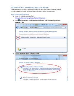


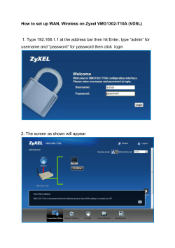

© Copyright 2026