
RFI Antenna Catalog - Wireless Communication Solutions
welcome to the revolution
RF Industries (RFI) is committed to the communications revolution. We have evolved
from the days of despatched two way radio to be a significant manufacturer of antenna
systems for the latest generation in wireless technologies. With continually expanding
export markets we have become a globally relevant manufacturer working with all levels
of the value chain across diverse markets including automotive, mobile telephony,
digital radio, wireless LAN, and industrial, scientific and medical (ISM) applications.
We strive to provide a service that is of world standard yet retains the agility of a small
player. Our motivated team of engineering and manufacturing professionals pride
themselves on their design philosophy of “bettering the best”. Our experience pays off
when new technologies require an antenna solution that matches the latest in
sophisticated design.
RFI utilises
· The latest in antenna design software
· Specialised test equipment
· An enormous depth of experience providing solutions to carriers,
manufacturers and end users
· A flexible manufacturing environment for base and mobile antennas
And we can supply everything else you need to complete your system. Antenna
combining equipment, coaxial cables, connectors, lightning protection, solar power, DC
power supplies, hand portable antennas, installation accessories…the lot!
This catalogue is intended as our definitive guide to RFI’s range of mobile and base
station antennas. We have included comprehensive accurate technical information on
each and every antenna offered for engineers, technicians and purchasing staff but we
cannot hope to cover every product in one catalogue.
Our most up to date information is always on our website and we encourage you to
utilise it when needed or alternatively contact one of our sales specialists for any further
information you may require.
Where is the next step for the wireless juggernaut….time will tell. What we do know is
that RFI will be there when it happens, providing solutions for the next revolution.
the RFI antenna catalogue
Trademarks
CELLFOAM® is a registered trademark of R F Industries Pty Ltd
CELLFOIL® is a registered trademark of R F Industries Pty Ltd
DUET™ is a trademark of R F Industries Pty Ltd
E-GLASS® is a registered trademark of R F Industries Pty Ltd
MOPOLE™ is a trademark of R F Industries Pty Ltd
PHASEMASTER™ is a trademark of R F Industries Pty Ltd
PHASEMASTER II™ is a trademark of R F Industries Pty Ltd
QUADRANT® is a registered trademark of R F Industries Pty Ltd
QUINTET™ is a trademark of R F Industries Pty Ltd
The Abstract Diamond Pattern device is a registered trademark of R F Industries Pty Ltd
RFI is R F Industries Pty Ltd
CINTA™ is a trademark of Andrew Corporation
CORAL™ is a trademark of Andrew Corporation
EASIAX® is a registered trademark of Andrew Corporation
GRIDPAK™ is a trademark of Andrew Corporation
HELIAX® is a registered trademark of Andrew Corporation
RADIAX® is a registered trademark of Andrew Corporation
SUREGROUND™ is a trademark of Andrew Corporation
Polyphaser® and LSX® are trade or service marks of Polyphaser Corporation
Corex® II is a registered trademark of Pressmaster AB
This catalogue is © 2005 R F Industries Pty Ltd
All rights remain with their respective owners.
Our policy and that of our partners is of continual improvement.
Product materials and specifications are subject to change without notice. © 2005 Australian and International Copyright
table of contents
base station antennas
Ground Plane Antennas
2
Coaxial Dipole Antennas
3–7
Side Mounted Dipole Antennas
8 – 14
Dipole Array Antennas
16 – 29
Collinear Antennas
30 – 48
Corner & Panel Reflector Antennas
49 – 51
Yagi Antennas
52 – 72
Gridpak Antennas
73
Phasing Harnesses
74 – 75
WLAN base station antennas
76 – 79
mobile antennas
VHF Unity Gain Roof Mount Antennas
83 – 94
UHF Roof Mount Antennas
95 – 103
VHF Low Profile Antennas
104 – 109
Trunking Glass Mount Antennas
110 – 113
Cellular Band Antennas
114 – 127
GPS antennas
128
WLAN antennas
129
UHFCBRS antennas
130 – 134
Marine antennas
135 – 138
hand portable antennas
140
accessories
Mopole Accessories
144
Mobile Antenna Accessories
145
Voltage Converters
146 – 148
Power Supplies
149
Coaxial Cables
151 – 154
Installation Cables
155
Coaxial Connectors
156 – 164
Coaxial Tools & Hardware
165 – 169
Mounting Hardware
170 – 175
Audio & Electrical Accessories
176 – 179
Panasonic Batteries
180
tech support
181 – 196
www.rfi.com.au
VHF Adjustable Ground Plane Antennas
70-175 MHz
The GP Series is a range of omnidirectional unity gain adjustable
ground plane antennas ideal for local area coverage when a high
gain antenna is not required or justified. The broad vertical
beamwidth offers excellent null fill for consistent signal coverage.
GP Series antennas are easily tuned in the field by adjusting the
position of the ground plane elements.
GP Series
Electrically, the GP Series antenna is a quarter wave radiating
element with the radials acting as a counterpoise. These radials
are of one-piece construction and utilise a unique single bolt
clamping design. The antennas are DC grounded for superior
lightning protection and the reduction of precipitation static noise.
• Easily field tuned by adjusting the position of the radials
• Lightweight and easy to mount
• Broad vertical beamwidth for excellent null fill
GP1
• Compact - Shipped disassembled for ease of handling
Typical VSWR response (GP1)
GP1 - E Plane
Electrical
Model Number
Nominal Gain dBi (dBd)
Frequency MHz
Tuned Bandwidth MHz
VSWR (Return Loss)
Nominal Impedance Ω
Vertical Beamwidth
Horizontal Beamwidth
Input Power W
GP1
GP3
GP4
GP2
137 - 151
10
148 - 175
15
2 (Unity)
70 - 85
5
118 - 136
10
<1.5 :1 (14dB)
50
110°
75°
Omni +/-0.5dB
200
Mechanical
Model Number
Construction
Length m
Weight kg
Termination
Mounting Area
Suggested Clamps
No ice
Projected
Area cm²
With ice
Wind Load (Thrust) @
160km/h N
Torque @160 km/h Nm
2
GP1
1.8
3.0
1752
3349
GP3
GP4
Heavy duty aluminium radiating element encased in a PVC radome
1.5
1.4
3.0
2.3
N female with 0.5m RG213 cable tail
500mm x 40mm diam. aluminium
2 x UB1 or 2 x UC1
1246
1121
2160
1959
GP2
1.3
2.0
988
1730
208
148
133
117
67
33
21
11
www.rfi.com.au
VHF Vertical Enclosed Dipole Antenna
30-50 MHz
COD30
The COD30 is a "cut to frequency" fibreglass enclosed vertical
dipole, ideal in single frequency or two antenna system
applications. The antenna provides low wind and tower loading.
The COD30 delivers unity gain omnidirectional coverage and
excellent null fill.
The COD30 is constructed with an alodined aluminium radiating
element enclosed within a fibreglass radome. The antenna is
end fed and terminated with a fixed N type female connector. A
DC short is incorporated for lightning protection and reduction of
precipitation static noise.
The antenna mounts via a 40mm diameter alodined aluminium
mount tube. The antenna is supplied pre-tuned to user specified
frequencies for immediate installation.
• Ideal in single frequency or two antenna system applications
• Unity gain, omnidirectional radiation pattern
Typical VSWR response (COD30)
-10
COD30 - E Plane
+10
COD30
Electrical
Model Number
Nominal Gain dBi (dBd)
Frequency MHz
Tuned Bandwidth
VSWR (Return Loss)
Nominal Impedance Ω
Vertical Beamwidth
Horizontal Beamwidth
Input Power W
COD30
2 (Unity)
30 - 50
1.0%
<1.5 :1 (14dB)
50
77°
Omni +/- 0.5dB
150
Mechanical
Model Number
Construction
Length m
Weight kg
Termination
Mounting Area
Suggested Clamps
No ice
Projected
Area cm²
With ice
Wind Load (Thrust) @
160km/h N
Torque @160 km/h Nm
www.rfi.com.au
COD30
Alodined aluminium elements with white fibreglass radome
5.5
4.0
N female bulkhead
500mm x 40mm diam. alodined aluminium
2 x UC1
1632
3291
193
447
3
VHF Vertical Enclosed Dipole Antennas
66-140 MHz
The COD1 series antennas are "cut to frequency" fibreglass
enclosed vertical dipoles, featuring extremely broad vertical
beamwidths and omnidirectional patterns for localised coverage.
COD1 Series
• Low wind and tower loading - ideal in conditions where high
winds are a factor.
• Ruggedised version (COD12) in an extra heavy duty black
fibreglass radome to maximise solar heat retention - aiding in
ice shedding
• Models available with 5% tuned bandwidth for duplex applications
• DC grounded for lightning protection and the reduction of
precipitation static noise
VSWR response (COD14) @140MHz
COD14 - E Plane
COD1
Electrical
Model Number
Nominal Gain dBi (dBd)
Frequency MHz
Tuned Bandwidth
VSWR (Return Loss)
Nominal Impedance Ω
Vertical Beamwidth
Horizontal Beamwidth
Input Power W
COD1
COD12
2 (Unity)
66 - 140
2.0%
COD14
5.0%
<1.5 :1 (14dB)
50
77°
76°
Omni +/- 0.5dB
150
200
Mechanical
Model Number
Construction
Length m
Weight kg
Termination
Suggested Clamps
No ice
With ice
Wind Load (Thrust) @
160km/h N
Wind Gust Rating km/h
Torque @160 km/h Nm
4
COD12
COD14
Alodined alum. elements with
white fibreglass radome
Alodined alum. elements
with ruggedised black
fibreglass radome
Alodined alum. elements with
white fibreglass radome
3.4
1.0
Mounting Area
Projected
Area cm²
COD1
280mm x 25mm diam.
alodined aluminium
2 x UB1
728
1706
3.0
3.2
N female bulkhead
500mm x 60mm diam.
alodined aluminium
2.7
2.5
600mm x 38mm diam.
stainless steel
2 x UC1
1568
2305
1297
2284
86
186
154
77
> 240
192
156
www.rfi.com.au
VHF Vertical Enclosed Dipole Antennas
140-205 MHz
The COD2 series antennas are "cut to frequency" fibreglass
enclosed vertical dipoles, featuring extremely broad vertical
beamwidths and omnidirectional patterns for localised coverage.
COD2 Series
• Low wind and tower loading
• Ruggedised version (COD22) in an extra heavy duty black
fibreglass radome to maximise solar heat retention - aiding in
ice shedding
• Stainless steel mounting version available (COD24) for
corrosive marine environments
• DC grounded for lightning protection and the reduction of
precipitation static noise
COD2 - E Plane
Typical VSWR response (COD2)
COD2
Electrical
Model Number
COD2
Nominal Gain dBi (dBd)
Frequency MHz
COD22
COD24
2 (Unity)
140 - 205
Tuned Bandwidth MHz
140 - 175
140 - 205
5
VSWR (Return Loss)
<1.5 :1 (14dB)
Nominal Impedance Ω
50
Vertical Beamwidth
78°
Horizontal Beamwidth
Omni +/- 0.5dB
Input Power W
100
Mechanical
Model Number
Construction
Length m
Weight kg
Termination
Mounting Area
Suggested Clamps
Projected
Area cm²
No ice
With ice
Wind Load (Thrust) @
160km/h N
Wind Gust Rating km/h
Torque @160 km/h Nm
www.rfi.com.au
COD2
COD22
COD24
Alodined aluminium elements
with white fibreglass radome
Alodined aluminium elements
with ruggedised black
fibreglass radome
Alodined aluminium elements
with white fibreglass radome
1.7
1.5
1.7
2.0
215mm x 25mm
diam. alodined aluminium
2 x UC1 or 2 x UB1
402
804
1.8
2.2
N female bulkhead
500mm x 60mm
diam. alodined aluminium
2 x UC1
873
1289
215mm x 25mm
diam. stainless steel
2 x UC1 or 2 x UB1
403
805
48
103
48
23
>240
45
24
5
UHF Vertical Enclosed Dipole Antennas
375-520 MHz
The COD4 series antennas are a range of fibreglass enclosed
vertical dipoles ideal in local coverage applications. COD4 series
antennas deliver extremely broad beamwidths which enhance
close-in coverage. They are supplied pre-tuned in set bands and
can be held as a stock antenna if required.
COD4
• Ideal for local area coverage
• Available spot tuned to user specified frequencies or in a
number of pre-determined band configurations
• Unity gain omnidirectional radiation pattern with excellent
null-fill characteristics
• Dual decoupling choke to ensure distortion-free pattern
Typical VSWR response (COD4)
COD4 - E Plane
COD4
Electrical
Model Number
Nominal Gain dBi (dBd)
Frequency MHz
Tuned Bandwidth
VSWR (Return Loss)
Nominal Impedance Ω
Vertical Beamwidth
Horizontal Beamwidth
Input Power W
Passive IM 3rd order dBc
COD4-65
COD4-70
400 - 420
450 - 470
COD4-65
COD4-71
COD4-63
2 (Unity)
470 - 490
480 - 500
Full
<1.5 :1 (14dB)
50
78°
Omni +/- 0.5dB
50
-125
COD4-72
COD4-99
500 - 520
375 - 520
4%
COD4-70
COD4-71
COD4-63
COD4-72
Alodined aluminium elements with white fibreglass radome
0.9
0.5
COD4-99
Mechanical
Model Number
Construction
Length m
Weight kg
1.0
Termination
Mounting Area
Suggested Clamps
No ice
Projected
Area cm²
With ice
Wind Load (Thrust) @
160km/h N
Wind Gust Rating km/h
Torque @160 km/h Nm
6
Variable
N female bulkhead
266
494
250
463
100mm x 25mm diam. alodined aluminium
2 x UC1 or 2 x UB1
250
250
463
463
250
463
270
497
32
30
32
10
>240
8
11
www.rfi.com.au
UHF Vertical Enclosed Dipole Antennas
600-960 MHz
The COD8 Series antennas are a range of fibreglass enclosed
vertical dipoles, ideal in point to multipoint, trunking, cellular and
local coverage area applications. The antenna has a relatively
broad bandwidth and easily accommodates both transmit and
receive portions of any of the common 800MHz operating bands.
COD8
• Available spot tuned to user specified frequencies or in a
number of pre-determined band configurations
• Excellent null fill coverage
• Omnidirectional unity gain performance
Typical VSWR response (COD8)
COD8 - E Plane
COD8
Electrical
Model Number
Nominal Gain dBi (dBd)
Frequency MHz
Tuned Bandwidth MHz
VSWR (Return Loss)
Nominal Impedance Ω
Vertical Beamwidth
Horizontal Beamwidth
Input Power W
Passive IM 3rd order dBc
COD8-81
COD8-82
2 (Unity)
850 - 930
820 - 880
Full
COD8-99
600 - 960
80
<1.5 :1 (14dB)
50
78°
Omni +/- 0.5dB
25
-120
Mechanical
Model Number
Construction
Length m
Weight kg
Termination
Mounting Area
Suggested Clamps
No ice
Projected
Area cm²
With ice
Wind Load (Thrust) @
160km/h N
Wind Gust Rating km/h
Torque @160 km/h Nm
www.rfi.com.au
COD8-81
COD8-82
COD8-99
Alodined aluminium elements with white fibreglass radome
0.8
Variable
0.5
N female bulkhead
315mm x 25mm diam.
325mm x 25mm diam.
230mm (minimum) x 25mm diam.
alodined aluminium
alodined aluminium
alodined aluminium
2 x UB1
267
266
285
488
484
525
32
32
34
5
>240
4
8
7
VHF Side Mounted Dipole Antennas
66-108 MHz
SMD1 Series
The SMD1 Series side mounted dipoles are broad band
antennas which, through different phasing and mounting
arrangements, can offer a variety of patterns (generally cardioid)
tailored to specific coverage requirements. These antennas can
be mounted in dual arrays for 3dB gain, or four-stack arrays for
6dB gain over a single dipole.
The SMD1 is constructed of heavy gauge corrosion resistant
anodised aluminium tubing with a high pressure cast aluminium
hub assembly and stainless steel fittings. This combination
provides an exceptionally strong antenna, suited for extreme
weather conditions.
SMD1
The SMD12, is a ruggedised antenna featuring extremely heavy
walled tubing, all welded alodined aluminium construction and a
black epoxy coating to aid in solar heat retention. The SMD14
is a stainless steel version and is ideal in corrosive marine
environments. All of the antennas are electrically identical.
SMD antenna construction allows for the entire antenna to rest
at ground potential making it highly recommended in lightning
prone applications.
• Can be phased to provide 3dBd or 6dBd gain in a variety of
patterns to suit specific requirements. See page 74 for our
full range of phasing harnesses.
• Full bandwidth coverage for both single antennas and
phased arrays - ideal in community sites
• Ruggedised and stainless steel versions available
• Normally available ex-stock for immediate delivery
SMD series antennas are supplied with a boom for ¼ wave antenna to mast
spacing. Booms for ½ wave spacing and full wave spacing are also available.
Application details on phasing and mounting of SMD antennas are included in
the technical notes at the back of this catalogue.
8
www.rfi.com.au
VHF Side Mounted Dipole Antennas
66-108 MHz
SMD1 Series
Typical VSWR response
(SMD1,12,14) at ¼ wave spacing
Typical VSWR response
(SMD1,12,14) at ½ wave spacing
H Plane at ¼ wave antenna
to mast spacing
H Plane at ½ wave antenna
to mast spacing
Peak gain at 0° of 1dBd
Peak gain at 90°, 270° of 1dBd
Electrical
Model Number
Nominal Gain dBi (dBd)
Frequency MHz
Tuned Bandwidth
VSWR (Return Loss)
Nominal Impedance Ω
Vertical Beamwidth
Horizontal Beamwidth
Input Power W
SMD1
SMD12
SMD14
Nominally 2 (Unity) but varies with mounting arrangements
70 - 85
Entire band
<1.5 :1 (14dB)
50
Typically 74° at ¼ λ antenna - mast spacing
Typically 260° at ¼ λ antenna - mast spacing
300
SMD1-99
66 - 108
10%
Mechanical
Model Number
Construction
Length m
Weight kg
Termination
Mounting Area
Suggested Clamps
No ice
Projected
Area cm²
With ice
Wind Load (Thrust) @
160km/h N
Torque @160 km/h Nm
www.rfi.com.au
SMD1
Thick walled aluminium
with cast aluminium hub
SMD12
SMD14
Heavy duty aluminium Stainless steel with cast
with black epoxy finish
aluminium hub
1.8
2.5
3.0
4.4
N female with RG213 cable tail
300mm x 38mm diam.
300mm x 40mm diam. aluminium
stainless steel
1 x UCR1 or UCR2
1566
1752
1501
3000
3157
2930
SMD1-99
Thick walled aluminium
with cast aluminium hub
1.9
3.0
300mm x 40mm diam.
aluminium
1872
3527
186
208
178
222
139
160
133
150
9
VHF Side Mounted Dipole Antennas
108-200 MHz
SMD2 Series
The SMD2 Series side mounted dipoles are broad band
antennas which, through different phasing and mounting
arrangements can offer a variety of patterns (generally cardioid)
tailored to specific coverage requirements. These antennas can
be mounted in dual arrays for 3dB gain, or four-stack arrays for
6dB gain over a single dipole.
The SMD2 is constructed of heavy gauge corrosion resistant
anodised aluminium tubing with a high pressure cast aluminium
hub assembly and stainless steel fittings. This combination
provides an exceptionally strong antenna, suited for extreme
weather conditions.
SMD2
The SMD22 is a ruggedised antenna featuring extremely heavy
walled tubing, all welded aluminium construction and a black
epoxy coating to aid in solar heat retention. The SMD24 is a
stainless steel version and is ideal in corrosive marine
environments. All of the antennas are electrically identical.
SMD antenna construction allows for the entire antenna to rest
at ground potential, making it highly recommended in lightning
prone applications.
• Can be phased to provide 3 dBd or 6 dBd gain, in a variety of
patterns tailored to suit specific requirements. See page 74
for our full range of phasing harnesses.
• Full bandwidth coverage for both single antennas and
phased arrays - ideal in community sites
• High strength - SMD2 features anodised aluminium
construction and high pressure cast aluminium centrepiece
• Rugged and stainless steel versions also available
• Normally available ex-stock for immediate delivery
All antennas are supplied with a boom for ¼ wave antenna to mast spacing.
Booms for ½ wave spacing and full wave spacing are also available.
Application details on phasing and mounting of SMD antennas are included in
the technical notes at the back of this catalogue.
10
www.rfi.com.au
VHF Side Mounted Dipole Antennas
108-200 MHz
SMD2 Series
Typical VSWR response
(SMD2,22,24) at ½ wave spacing
Typical VSWR response
(SMD2,22,24) at ¼ wave spacing
H Plane at ¼ wave antenna
to mast spacing
H Plane at ½ wave antenna
to mast spacing
Peak gain at 90°, 270° of 2dBd
Peak gain at 0° of 1dBd
Electrical
Model Number
Nominal Gain dBi (dBd)
Frequency MHz
Tuned Bandwidth
VSWR (Return Loss)
Nominal Impedance Ω
Vertical Beamwidth
Horizontal Beamwidth
Input Power W
SMD2
SMD22
SMD24
Nominally 2 (Unity) but varies with mounting arrangements
148 - 175
Entire band
<1.5 :1 (14dB)
50
Typically 74° at ¼ λ antenna - mast spacing
Typically 230° at ¼ λ antenna - mast spacing
250
SMD2-99
108 - 200
10%
Mechanical
Model Number
Construction
Length m
Weight kg
Termination
Mounting Area
Suggested Clamps
No ice
Projected
Area cm²
With ice
Wind Load (Thrust) @
160km/h N
Torque @160 km/h Nm
www.rfi.com.au
SMD2
Thick walled aluminium
with cast aluminium hub
SMD22
SMD24
SMD2-99
Heavy duty aluminium Stainless steel with cast Thick walled aluminium
with black epoxy finish
aluminium hub
with cast aluminium hub
0.9
1.3
1.5
2.0
3.0
2.0
N female with RG213 cable tail
300mm x 38mm diam.
300mm x 40mm diam.
300mm x 40mm diam. aluminium
stainless steel
aluminium
1 x UCR1 or UCR2
849
927
810
1373
1644
1633
1604
2524
101
110
96
163
50
57
48
110
11
UHF Side Mounted Dipole Antennas
360-600 MHz
SMD4 Series
The SMD4 series are a range of unity gain side mounted dipoles
which can be used as a single antenna for short range
applications or, if desired, phased together to provide high gain
array coverage characteristics.
The SMD4-67 is of all welded aluminium construction. The feed
point is protected by an ABS cap, with the internal PTFE based
cable construction providing excellent intermodulation
performance (-150dBc).
The stainless steel SMD41-67 is electrically identical to its aluminium
counterpart and is recommended for corrosive environments.
SMD4-67
All of the SMD4 series antennas are directly DC grounded for
superior lightning protection and the reduction of precipitation
static noise.
The SMD4 Series antennas are supplied with a boom for ¼
wave antenna to mast spacing. Application details on phasing
and mounting of SMD antennas are included in the technical
notes at the back of this catalogue.
• Versatile - Antennas can be phased and manipulated to achieve
a variety of horizontal radiation patterns and varying gains. See
page 74 for our full range of phasing harnesses
• Stock Antennas - Generally available off the shelf
• Lightweight - Easily mounted and installed with single clamps
• All welded, full folded dipole construction
• Varying boom lengths available to suit coverage requirements
The SMD4-99 is a specific frequency version of the SMD4. This antenna is
designed only for use as a single dipole, not as a component of a phased
dipole array as the antenna is custom made to user specified frequencies and
is not specifically matched to a phasing harness. It can be ordered with a
specified centre frequency anywhere in the band from 360 to 600 MHz with an
operating bandwidth of approximately 20% of centre frequency.
12
www.rfi.com.au
UHF Side Mounted Dipole Antennas
360-600 MHz
SMD4 Series
Typical VSWR response (SMD4-67)
SMD4-67 - H Plane
SMD4-67 at ¼
wave antenna to
mast spacing
Peak gain at 0° of 2dBd
Electrical
Model Number
Nominal Gain dBi (dBd)
Frequency MHz
Tuned Bandwidth
VSWR (Return Loss)
Nominal Impedance Ω
Vertical Beamwidth
Horizontal Beamwidth
Input Power W
Passive IM 3rd order dBc
SMD4-67
SMD41-67
SMD4-99
Nominally 2 (Unity) but varies with mounting arrangements
400 - 520
360 - 600
Entire band
20.0%
<1.5 :1 (14dB)
50
Typically 70° at ¼ λ antenna - mast spacing
Typically 220° at ¼ λ antenna - mast spacing
500
-150
SMD41-99
Mechanical
Model Number
Construction
Length m
Weight kg
Termination
Mounting Area
Suggested Clamps
No ice
Projected
Area cm²
With ice
Wind Load (Thrust) @
160km/h N
Wind Gust Rating km/h
Torque @160 km/h Nm
www.rfi.com.au
SMD4-67
All welded aluminium
with alodined finish
0.4
0.3
SMD41-67
SMD4-99
All welded aluminium
Stainless steel
with alodined finish
0.4
0.5
0.6
0.3
N female with short 9142 cable tail
100mm x 25mm diam. alodined aluminium
1 x UNV
SMD41-99
Stainless steel
0.5
0.6
200
423
213
480
24
25
>240
3
5
13
UHF Side Mounted Dipole Antenna
806-960 MHz
The SMD8-90 side mount dipole is an extremely broad
bandwidth antenna recommended for local area coverage or
short haul RF link applications.
SMD8-90
The antenna is internally DC grounded for lightning protection
and the reduction of precipitation static noise.
• Provides either directional or largely omnidirectional
radiation pattern
• All welded and alodined aluminium construction
SMD8-90
Please note, we recommend against phasing the SMD8-90 antenna as the
required accuracy is far too critical to be adequately controlled in the field.
Thus, we do not publish any information to assist in the phasing of our 800
MHz side mount dipole antennas.
Typical VSWR response (SMD8-90)
SMD8-90 H Plane at ¼ wave
antenna to mast spacing
Peak gain at 0° of 2dBd
Electrical
Model Number
Nominal Gain dBi (dBd)
Frequency MHz
Tuned Bandwidth
VSWR (Return Loss)
Nominal Impedance Ω
Vertical Beamwidth
Horizontal Beamwidth
Input Power W
SMD8-90
Nominally 2 (Unity) but varies with mounting arrangements
806 - 960
Entire band
<1.5 :1 (14dB)
50
Typically 85° at ¼ λ antenna - mast spacing
Typically 213° at ¼ λ antenna - mast spacing
200
Mechanical
Model Number
Construction
Length m
Weight kg
Termination
Mounting Area
Suggested Clamps
No ice
Projected
Area cm²
With ice
Wind Load (Thrust) @
160km/h N
Wind Gust Rating km/h
Torque @160 km/h Nm
14
SMD8-90
All welded aluminium with alodined finish
0.3
0.2
N female with short 9142 cable tail
100mm x 25mm diam. alodined aluminium
1 x UNV
96
227
11
>240
1
www.rfi.com.au
waves
do you
subscribe?
RFI’s quarterly newsletter
packed with:
news
Z tech tips
Z new products
Z
Available in hardcopy or
softcopy. To subscribe visit
www.rfi.com.au
VHF Omnidirectional Dipole Arrays
136-174 MHz
BA40-41 Series
BA80-41 Series
These high performance VHF dipole omnidirectional arrays are
for use in highly populated radio sites requiring long haul
omnidirectional coverage. The arrays feature high gain, low
noise performance and enhanced null fill coverage with
omnidirectional coverage characteristics.
Each of the dipoles are fed via an internal phasing harness in
stable, PTFE based double-screened coaxial cable with PE
jacket for optimum weatherproofing. These omnidirectional
arrays incorporate extensive side lobe suppression and null fill,
and the binary phasing arrangement ensures consistent
omnidirectional coverage and vertical pattern control.
These arrays provide unparalleled bandwidth, covering the
entire 136-174 MHz band and offer gain of 3 or 6dBd over that
band with a VSWR of less than 1.5:1. With input power levels of
750 watts, the antennas are suitable for high power paging sites
or high density, multi-channel installations requiring maximum
performance and service life.
BA40-41
With all welded construction and superior internal harness
construction, these antennas provide not only excellent pattern
characteristics but also defined, high levels of intermodulation
and noise suppression. The entire array rests at ground potential
and offers the ultimate in lightning resistant antennas.
• High gain omnidirectional patterns
• Operate over entire 136-174 MHz VHF band without tuning
or adjustment
• Modular mix and match format allows future-proofing installations
• 3° downtilt option available on BA80 (four pair) version
• Inverted mounting version available
• Industry leading PIM ratings (-150dBc) providing low IM
and low noise characteristics for optimum performance
Options available include
• All stainless steel 316 grade construction (3dBd array only)
• Inverted mounting configuration
• BA80-41 may be operated as 2 x 3dBd arrays by removing external
cable harness
16
www.rfi.com.au
VHF Omnidirectional Dipole Arrays
136-174 MHz
BA40-41 Series
BA80-41 Series
Typical VSWR response (BA40-41)
Typical VSWR response (BA80-41)
BA40-41 - E Plane
BA80-41 - E Plane
Electrical
Model Number
Nominal Gain dBi (dBd)
Frequency MHz
Tuned Bandwidth
VSWR (Return Loss)
Nominal Impedance Ω
Downtilt
Vertical Beamwidth
Horizontal Beamwidth
Input Power W
Passive IM 3rd order dBc
BA40-41
5 (3)
BA80-41
8 (6)
136 - 174
Entire band
<1.5 :1 (14dB)
50
Not offered
35°
0° Std, -3°. See note (1)
18°
Omni +/-0.5dB
750
-150
Mechanical
Model Number
Construction
Length m
Weight kg
Termination
Mounting Area
Suggested Clamps
No ice
Projected
Area cm²
With ice
Wind Load (Thrust) @
160km/h N
Wind Gust Rating km/h
Torque @160 km/h Nm
BA40-41
BA80-41
All welded aluminium with alodined finish. See note (2)
3.5
6.3
14.5
31
N female with 0.5m 9142 cable tail. See note (3)
500mm x 63mm diam. aluminium
500mm x 76mm diam. aluminium
2 x UC1
4164
8294
7117
13325
494
983
240
617
184
2605
(1) Factory pre-set downtilt of 3° may be specified on BA80 series antennas using model no. trailer -T3
(2) BA40 series can be optionally supplied in all welded 316 grade stainless steel. Dimensions vary slightly
(3) Connector termination option available of 7/16 DIN female connector using model no. trailer -DIN
www.rfi.com.au
17
VHF Elliptical Dipole Arrays
136-174 MHz
These high performance VHF binary phased elliptical arrays are
ideal for the bi-directional coverage requirement of paging and
VHF high band mobile “corridor” applications. The main lobe of
these arrays is strong and highly controlled with extensive side
lobe suppression ensuring the integrity of the pattern.
EA40-41
EA80-41
The folded dipoles utilise an internal phasing harness in stable,
PTFE based double-screened coaxial cable with PE Jacket for
optimal weatherproofing. These elliptical arrays incorporate
extensive side lobe suppression, null fill, and accommodate
power input levels of 750 watts continuous.
With all welded construction and superior internal harness
construction these antennas provide not only excellent radiation
characteristics but also high levels of intermodulation and noise
suppression. The entire array rests at ground potential and offers
the ultimate in lightning resistant antennas.
• High gain elliptical pattern with 5dBd or 8dBd versions available
• Operate over entire 136-174 MHz band without tuning
or adjustment
• Inverted mounting version available
EA40-41
• Industry leading PIM ratings (-150dBc) providing low IM
and low noise characteristics for optimum performance
Options available include
• All stainless steel 316 grade construction (5dBd array only)
• Inverted mounting configuration
•EA40-41 may be operated as 2 x 5dBd arrays by removing external
cable harness
18
www.rfi.com.au
VHF Elliptical Dipole Arrays
136-174 MHz
EA40-41
EA80-41
Typical VSWR response (EA40-41)
EA40-41 - E Plane
EA40-41 - H Plane
Typical VSWR response (EA80-41)
EA80-41 - E Plane
EA80-41 - H Plane
Electrical
Model Number
Nominal Gain dBi (dBd)
Frequency MHz
Tuned Bandwidth
VSWR (Return Loss)
Nominal Impedance Ω
Downtilt
Vertical Beamwidth
Horizontal Beamwidth
Input Power W
Passive IM 3rd order dBc
EA40-41
7 (5)
EA80-41
10 (8)
136 - 174
Entire band
<1.5 :1 (14dB)
50
Not offered
35°
104°
0° Std, -3°. See note (1)
17°
128°
750
-150
Mechanical
Model Number
Construction
Length m
Weight kg
Termination
Mounting Area
Suggested Clamps
No ice
Projected
Area cm²
With ice
Wind Load (Thrust) @
160km/h N
Wind Gust Rating km/h
Torque @160 km/h Nm
EA40-41
EA80-41
All welded aluminium with alodined finish. See note (2)
3.5
6.3
14.5
31.0
N female with 0.5m 9142 cable tail. See note (3)
500mm x 63mm diam. aluminium
500mm x 76mm diam. aluminium
2 x UC1
4781
9513
8701
16475
567
1127
240
708
175
2988
(1) Factory pre-set downtilt of 3° may be specified on EA80 series antennas using model no. trailer -T3
(2) EA40 series can be optionally supplied in all welded 316 grade stainless steel. Dimensions vary slightly
(3) Connector termination option available of 7/16 DIN female connector using model no. trailer -DIN
www.rfi.com.au
19
VHF Offset Dipole Arrays
136-174 MHz
These high performance VHF dipole offset arrays are ideal for
use when a cardioid pattern is required. The arrays feature high
gain, low noise performance and enhanced null fill coverage with
typical cardioid coverage characteristics.
OA20-41
OA40-41
OA series arrays have an almost full 180° horizontal beamwidth.
This eliminates the possibility of fading at the extremities of the
target coverage area. Antenna gain is approximately unity at the
rear of the antenna.
As would be expected from a cardioid array, the vertical
beamwidth is slightly greater than its BA (omnidirectional) or EA
(elliptical) pattern counterparts.
OA series arrays feature the same solid construction as the BA
and EA Series. The folded dipoles utilise an internal phasing
harness in stable, PTFE based double-screened coaxial cable
with PE jacket for optimum weatherproofing. The offset arrays
incorporate extensive side lobe suppression, null fill, and power
input level of 750 watts continuous.
With all welded construction and superior internal harness
construction these antennas provide not only excellent pattern
characteristics but also high levels of intermodulation and noise
suppression. The entire array rests at ground potential and
offers the ultimate in lightning resistant antennas.
OA20-41
• High gain offset (cardioid) pattern. 5dBd or 9dBd versions available
• Operate over entire 136-174 MHz VHF band without tuning
or adjustment
• Modular mix and match format allows future-proofing installations
• 3° downtilt option available
• Inverted mounting version available
• Industry leading PIM ratings (-150dBc) providing low IM
and low noise characteristics for optimum performance
Options available include
• All stainless steel 316 grade construction (5dBd array only)
• Inverted mounting configuration
• OA40-41 may be operated as 2 x 5dBd arrays by removing external
cable harness
20
www.rfi.com.au
VHF Offset Dipole Arrays
136 - 174 MHz
OA20-41
OA40-41
Typical VSWR response (OA20-41)
OA20-41 - E Plane
OA20-41 - H Plane
Typical VSWR response (OA40-41)
OA40-41 - E Plane
OA40-41 - H Plane
Electrical
Model Number
Nominal Gain dBi (dBd)
Frequency MHz
Tuned Bandwidth MHz
VSWR (Return Loss)
Nominal Impedance Ω
Downtilt
Vertical Beamwidth
Horizontal Beamwidth
Input Power W
Passive IM 3rd order dBc
OA20-41
7 (5)
OA40-41
11 (9)
136 - 174
Entire band
<1.5 :1 (14dB)
50
Not offered
35°
178°
0 Std, -3°. See note (1)
17°
176°
750
-150
Mechanical
Model Number
Construction
Length m
Weight kg
Termination
Mounting Area
Suggested Clamps
Projected
Area cm²
No ice
With ice
Wind Load (Thrust) @
160km/h N
Wind Gust Rating km/h
Torque @160 km/h Nm
OA20-41
OA40-41
All welded aluminium with alodined finish. See note (2) for stainless steel options.
3.5
6.3
12.5
29.0
N female with 0.5m 9142 cable tail. See note (3).
500mm x 63mm diam. aluminium
500mm x 76mm diam. aluminium
2 x UC1
3710
7396
6188
11481
440
877
240
550
191
2323
(1) Factory pre-set downtilt of 3° may be specified on OA40 series antennas using model no. trailer - T3
(2) OA20 series can be optionally supplied in all welded 316 grade stainless steel. Dimensions vary slightly
(3) Connector termination option available of 7/16 DIN female connector using model no. trailer -DIN
www.rfi.com.au
21
UHF Omnidirectional Dipole Arrays
330-520 MHz
BA40 Series
BA80 Series
BA160 Series
These high performance UHF dipole arrays are ideal for highly
populated radio sites requiring long haul omnidirectional
coverage. They operate over entire bands and offer gains of 3, 6
or 9dBd (depending on model) exhibiting a VSWR of <1.5:1
across the band.
The arrays utilise an internal phasing harness in PTFE based
double screened coaxial cable with polyethylene jacket to aid
waterproofing and resist bird attack. The use of a unique
phasing arrangement provides extensive side lobe suppression
and null fill characteristics. The arrays will accept an input
power level of 500 watts continuous, making them ideal for high
power multiple transmitter applications. The BA80 series are
offered with 3°, 5° or 8° downtilt, to further enhance close-in
coverage characteristics.
All welded alodined aluminium construction and new fabrication
techniques in both the harness and dipole sections have proven
to minimise intermodulation and noise generated within the
antennas. The entire array rests at ground potential and offers
the ultimate in lightning resistant antennas.
• Ideal for highly populated sites requiring long haul
omnidirectional coverage
• Operate over entire 330-420 or 400-520 MHz bands
• 3, 6 or 9 dBd gain versions available
BA80
• Inverted mounting version available
• Versions with 0°, 3°, 5° or 8° of downtilt available
• Extensive side lobe suppression and null fill
• Industry leading PIM ratings (-150dBc) providing low IM
and low noise characteristics for optimum performance
22
www.rfi.com.au
UHF Omnidirectional Dipole Arrays
330-520 MHz
BA40 Series
BA80 Series
BA160 Series
Typical VSWR response (BA40-67)
Typical VSWR response (BA80-67)
Typical VSWR response (BA160-67-T3)
-100
BA40-67 - E Plane
BA80-67 - E Plane
+100
BA160-67 - E Plane
Electrical
Model Number
Nominal Gain dBi (dBd)
Frequency MHz
Tuned Bandwidth
VSWR (Return Loss)
Nominal Impedance Ω
Downtilt
Vertical Beamwidth
Horizontal Beamwidth
Input Power (Watts)
Passive IM 3rd order dBc
BA40-57
BA40-67
BA80-57
5 (3)
330 - 420
BA80-67
8 (6)
400 - 520
Not offered
30°
330 - 420
Entire band
<1.5 :1 (14dB)
50
0° Std, -3°, -5°, -8°. See note (1)
16°
Omni +/- 0.5dB
500
-150
BA160-67-T3
11 (9)
400 - 520
3°
9°
Mechanical
Model Number
Construction
Length m
Weight kg
Termination
Mounting Area
Suggested Clamps
Projected
No ice
Area cm²
With ice
Wind Load (Thrust) @
160km/h N
Wind Gust Rating km/h
Torque @160 km/h Nm
BA40-57
BA40-67
BA80-57
BA80-67
BA160-67-T3
All welded aluminium with alodined finish. See (2) and (3) for alternate finishes
2.1
2.1
3.0
5.0
5.0
8.0
20.0
N female with 0.5m 9142 cable tail. See note (4)
500mm x 63mm
500mm x 48mm diam. aluminium
diam. aluminium
2 x UC1
1913
1833
3222
3063
6040
3182
2990
5835
5451
10085
227
217
382
363
716
111
235
382
240
363
216
1417
240
116
(1) Factory pre-set downtilt of 3°, 5° or 8° may be specified on BA80 series antennas using model no. trailer - T3, -T5 or -T8
(2) Ruggedised black powder coat finish (aids in ice shedding for extreme conditions) is available on all aluminium arrays.
(3) BA40 and BA80 series may be optionally supplied in all welded 316 Marine Grade Stainless steel. Dimensions vary slightly
(4) Connector termination option available of 7/16 DIN female connector using model no. trailer -DIN
www.rfi.com.au
23
UHF Elliptical Dipole Arrays
330-520 MHz
EA40 Series
EA80 Series
The EA series arrays provide exceptionally high gain with an
elliptical shaped radiation pattern, ideal for the bi-directional
coverage requirements of some "corridor" applications.
The array utilises an internal phasing harness in PTFE based
double screened coaxial cable with polyethylene jacket to aid
waterproofing and resist bird attack.
The main lobe of these antennas is strong and highly controlled
with extensive side lobe suppression ensuring the integrity of the
pattern. To further boost performance, users of the EA80 array
may specify beamtilt of 0, -3 or -5 degrees. Superior
performance is maintained over the entire operating bandwidth
of the antenna (330-420 MHz or 400-520 MHz). VSWR is
maintained at <1.5:1 and input power levels of 500 watts are
catered to for true high density site requirements.
With all welded construction and superior internal harness
construction (using highly stable PTFE based cables) the
antennas provide not only excellent radiation characteristics but
also high levels of intermodulation and noise suppression. IM
performance is a world leading -150dBC based on a two carrier
test. The entire array rests at ground potential and offers the
ultimate in lightning resistant antennas.
EA80
• Ideal for highly populated sites requiring "corridor" style
largely bidirectional coverage
• 5dBd or 8dBd gain versions available
• Inverted mounting version available
• 0°, 3° or 5° of downtilt available
• Extensive side lobe suppression and null fill
• Hermetically sealed internal phasing harness
• Industry leading PIM ratings (-150dBc) providing low IM
and low noise characteristics for optimum performance
24
www.rfi.com.au
UHF Elliptical Dipole Arrays
330-520 MHz
EA40 Series
EA80 Series
Typical VSWR response (EA40-67)
EA40-67 - E Plane
EA40-67 - H Plane
Typical VSWR response (EA80-67)
EA80-67 - E Plane
EA80-67 - H Plane
Electrical
Model Number
Nominal Gain dBi (dBd)
Frequency MHz
Tuned Bandwidth MHz
VSWR (Return Loss)
Nominal Impedance Ω
Downtilt
Vertical Beamwidth
Horizontal Beamwidth
Input Power W
Passive IM 3rd order dBc
EA80-57
10 (8)
330 - 420
Not offered
17°
74°
EA40-67
7 (5)
EA80-67
10 (8)
400 - 520
Entire band
<1.5 :1 (14dB)
50
Not offered
34°
70°
500
-150
0° Std -3°, -5°. See note (1)
17°
74°
Mechanical
Model Number
Construction
Length m
Weight kg
Termination
Mounting Area
Suggested Clamps
No ice
Projected
Area cm²
With ice
Wind Load (Thrust) @
160km/h N
Wind Gust Rating km/h
Torque @160 km/h Nm
EA80-57
EA80-67
3827
7053
EA40-67
All welded aluminium with alodined finish. See note (2)
2.1
5.0
N female with 0.5m 9142 cable tail. See note (3)
500mm x 48mm diam. aluminium
2 x UC1
2118
3527
454
251
431
226
454
240
128
219
431
3.0
8.0
3.0
8.0
3633
6527
(1) Factory pre-set downtilt of 3° or 5° may be specified on EA80-67 series antennas using model no. trailer -T3 or -T5
(2) EA40 and EA80 series may be optionally supplied in all welded 316 Marine Grade Stainless steel. Dimensions vary slightly
(3) Connector termination option available of 7/16 DIN female connector using model no. trailer -DIN
www.rfi.com.au
25
UHF Offset Dipole Arrays
330-520 MHz
OA20 Series
OA40 Series
Offset arrays are directional antennas for use when a base station
is at one end of the coverage area. These new arrays feature
improved gains, low noise performance and enhanced null fill
coverage in an array with typical cardioid coverage characteristics.
OA Series arrays feature the same solid construction as the BA
and EA series. The array utilises an internal phasing harness in
PTFE based double screened coaxial cable with polyethylene
jacket to aid waterproofing and resist bird attack.
The OA Series have slightly more than 170° horizontal
beamwidth, thus everything in front of the antenna is given
coverage. This eliminates the possibility of fading at the
extremities of the target coverage area. The level of radiation at
the rear of the antenna is approximately unity gain.
As would be expected from a cardioid array, the vertical
beamwidth is slightly greater than its BA omnidirectional or EA
elliptical pattern counterparts.
These antennas are also offered with -3°, -5° or -8° of beamtilt,
and all include extensive side lobe suppression, null fill and a
power input level of 500 Watts continuous.
• Operate over entire 330-420MHz or 400-520 MHz bands
• Inverted mounting version available
OA40
• 5dBd or 9dBd gain versions available
• Hermetically sealed internal phasing harness
• Industry leading PIM ratings (-150dBc) providing low IM
and low noise characteristics for optimum performance
26
www.rfi.com.au
UHF Offset Dipole Arrays
330-520 MHz
OA20 Series
OA40 Series
Typical VSWR response (OA20-67)
OA20-67 - E Plane
OA20-67 - H Plane
Typical VSWR response (OA40-67)
OA40-67 - E Plane
OA40-67 - H Plane
Electrical
Model Number
Nominal Gain dBi (dBd)
Frequency MHz
Tuned Bandwidth MHz
VSWR (Return Loss)
Nominal Impedance Ω
Downtilt
Vertical Beamwidth
Horizontal Beamwidth
Input Power (Watts)
Passive IM 3rdOrder dBc
OA20-57
OA20-67
OA40-57
7 (5)
330 - 420
OA40-67
11 (9)
400 - 520
330 - 420
400 - 520
Entire band
<1.5 :1 (14dB)
50
Not offered
35°
175°
0° Std, -3°, -5°, -8°. See Note (1)
17°
173°
178°
180°
500
-150
Mechanical
Model Number
Construction
Length m
Weight kg
Termination
Mounting Area
Suggested Clamps
No ice
Projected
Area cm²
With ice
Wind Load (Thrust) @
160km/h N
Wind Gust Rating km/h
Torque @160 km/h Nm
OA20-57
OA20-67
OA40-57
OA40-67
All welded aluminium with alodined finish. See notes (2) and (3) for alternative finishes.
2.1
3.0
4.0
6.5
N female with 0.5m 9142 cable tail. See note (4).
500mm x 48mm diam. aluminium
2 x UC1
1694
1646
2785
2688
2697
2565
4865
4602
201
195
102
99
330
319
330
319
>240
(1) Factory pre-set downtilt may be specified on OA40 series antennas using model no. trailer - T3, -T5 or -T8
(2) Ruggedised black powder coated finish (aids in ice shedding for extreme conditions) is available on all aluminium arrays
(3) OA20 and OA40 series may be optionally supplied in all welded 316 Marine Grade Stainless steel. Dimensions vary slightly
(4) Connector termination option available of 7/16 DIN female connector using model no. trailer - DIN
www.rfi.com.au
27
Array Combinations
330-520 MHz
The RFI range of UHF dipole arrays provide expanded
bandwidth, high power ratings and unequalled performance in
gain, pattern and intermodulation performance.
UHF Array
Combinations
Ever increasing costs and site density requirements are reducing
availability of antenna positions on prime sites. In order to
reduce the overall number of antennas the RFI dipole array
series provides system engineers and site owners with a flexible
solution to reduce antenna numbers.
Single Section Multiple Array
The RFI combination arrays are available in three types:
The Single Section Multiple Array
A combination of two arrays mounted upon a single piece of
48.4mm diameter, 3 meter length mast section. These arrays are
common where any combination of medium gain UHF
omnidirectional, offset or elliptical arrays are required. The
feeding of each of the arrays is via separate coaxial cable tails at
the base of the array.
Some common configuration examples are shown in the following
tables. The electrical specifications are very similar to those
provided for the individual arrays listed within the catalogue.
Shown on the left is the BA4040-67.
The Dual Section Combination Dipole Array
Dual Section Combination Array
These arrays are provided in two sections for ease of shipping
and handling and can be assembled on site.
The lower section array is made on a larger diameter mast
stock, the upper array telescoping into the lower section. Both
upper and lower arrays can be any one of our standard UHF
arrays or be externally coupled for even higher gain using a
PH42-67 phasing harness. This type of configuration provides
unrestricted gain, pattern and beamtilt combinations.
Some more common configuration examples are shown in the
following table. The electrical specifications are very similar to
those provided for the individual arrays previously listed within
the catalogue. Shown on the left is the BA80-67L lower section
with OA40-67 upper section.
Combination Collinear and Array
The Combination Collinear and Dipole Array
28
Similar in many regards to the above arrays this type of
combination array employs a collinear antenna as the upper
section of the array. These arrays are ideal where tower wind
loading is a critical consideration. The collinear antenna fits into
a lower section array, which can be essentially any style of our
higher gain UHF dipole arrays.
The collinear antenna (COL8 or COL17) is held in an adaptor
which can be fitted to any appropriately configured UHF
dipole array.
A sample of the more common configurations are provided in the
following table. The electrical specifications are very similar to
those provided for the individual arrays previously listed within
the catalogue. Shown on the left is the BX80-67 lower section
with COL8 upper section.
www.rfi.com.au
Array Combinations
Ordering Details
Single Section Multiple Arrays
Part number
Omnis
BA4040-57
BA4040-67
Elliptical
EA4040-57
EA4040-67
Offset Sections
OA2020-67
Description
Frequency
2 x 3dBd omnis with separate feeds
2 x 3dBd omnis with separate feeds
330-420MHz
400-520MHz
2 x 5dBd ellipticals with separate feeds
2 x 5dBd ellipticals with separate feeds
330-420MHz
400-520MHz
2 x 5dBd offsets with separate feeds
400-520MHz
Dual Section Combination Dipole Arrays
Shown below are lower sections only which include a through harness to connect your choice of upper section. Select
your upper section from the arrays section shown on pages 22 to 27.
Part number
Omnis
BA4040-57L
BA80-57L
BA4040-67L
BA80-67L
Elliptical Sections
EA4040-57L
EA80-57L
EA4040-67L
EA80-67L
Offset Sections
OA2020-67L
OA40-67L
Description
Frequency
2 x 3dBd omnis with separate feeds
1 x 6dBd omni
2 x 3dBd omnis with separate feeds
1 x 6dBd omni
330-420MHz
330-420MHz
400-520MHz
400-520MHz
2 x 5dBd ellipticals with separate feeds
1 x 8dBd elliptical
2 x 5dBd ellipticals with separate feeds
1 x 8dBd elliptical
330-420MHz
330-420MHz
400-520MHz
400-520MHz
2 x 5dBd offsets with separate feeds
1 x 9dBd offset
400-520MHz
400-520MHz
When ordering a dual section combination array you will need to order as follows:
1. Specify your lower Section from the list above eg: BA80-67L PLUS
2. Specify your single upper section from pages 22 to 27. eg: OA40-67.
Combination Collinear and Dipole Arrays
These lower sections are for use with COL series collinears. They are provided with a through harness to connect
your choice of COL8 (UHF), COL15 (VHF) or COL17 (VHF) collinears.
Omnis
BX40-67
BX4040-67
BX80-67
Elliptical Sections
EX40-67
EX4040-67
EX80-67
Offset Sections
OX2020-67
OX40-67
1 x 3dBd omni
2 x 3dBd omnis with separate feeds
1 x 6dBd omni
400-520MHz
400-520MHz
400-520MHz
1 x 5dBd elliptical
2 x 5dBd ellipticals with separate feeds
1 x 8dBd elliptical
400-520MHz
400-520MHz
400-520MHz
2 x 5dBd offsets with separate feeds
1 x 9dBd offset
400-520MHz
400-520MHz
When ordering a combination collinear and dipole array you will need to order as follows:
1. Specify your lower Section from the list above eg: BX80-67 PLUS
2. Specify your COL collinear either COL15, COL17 or COL8 eg: COL8 (and remember to specify frequency)
www.rfi.com.au
29
VHF Vertical Collinear Antennas
66-88 MHz
The 66-88 MHz COL range is a series of "cut to frequency" 3dBd
gain vertical collinears. The range includes models suitable for
simplex, duplex and heavy duty applications. They all include
internal DC grounding for lightning protection and the reduction
of static noise. Drainage vents at the base allow the antennas to
'breathe' and thus prevent condensation build up.
COL16
COL1
COL34-T1
COL16
The COL16 is specifically designed to cater for transmit to
receive separations of up to 2.0 MHz. The antenna is a series
fed Collinear which is housed in a heavy duty tapered fibreglass
radome, fitted with a alodined aluminium mounting tube. The
COL16 (and the electrically identical COL1) have been
specifically designed to maintain stable vertical radiation pattern
characteristics at the extremities of the tuned bandwidth. This
ensures reciprocity of transmit and receive signal characteristics.
COL1
The COL1 is an electrically identical internal design to the
COL16 with ruggedised construction, designed for use in the
most extreme climatic conditions. The radome which houses
the active elements of the COL1 was originally designed to
serve as the mast of recreational sail boards and is immensely
strong. The radome is coloured black to maximise solar heat
retention and this has been shown to aid significantly in ice
shedding. The antenna is fitted with a large, 60mm diameter
alodined aluminium mounting tube.
COL34-T1
The COL34 is a two piece antenna designed for applications
where the overall length of collinears for this band create
transportation/ logistic issues. The antenna employs a machined
brass coupling to ensure long term integrity over the service life
of the antenna.
COL1
30
www.rfi.com.au
VHF Vertical Collinear Antennas
66-88 MHz
COL16
COL1
COL34-T1
Typical VSWR response (COL16)
Typical VSWR response (COL34-T1)
-2.5
+2.5
COL34-T1 - E Plane
COL16 - E Plane
Electrical
Model Number
Nominal Gain dBi (dBd)
Frequency MHz
Tuned Bandwidth
VSWR (Return Loss)
Nominal Impedance Ω
Vertical Beamwidth
Horizontal Beamwidth
Input Power W
COL16
COL1
5 (3)
67 - 88
70 - 88
3.0%
COL34-T1
4 (2)
66 - 88
3.7%
<1.5 :1 (14dB)
50
36°
40°
Omni +/- 0.5dB
200
100
Mechanical
Model Number
Construction
Length m
Weight kg
COL16
COL1
COL34-T1
Alodined aluminium elements
with white fibreglass radome
Alodined aluminium elements
with ruggedised black
fibreglass radome
Two part antenna joins with brass
ferrules. White fibreglass radome
5.9
4.5
5.8
8.0
5.2
4.0
Termination
Mounting Area
Suggested Clamps
No ice
Projected
Area cm²
With ice
Wind Load (Thrust) @
160km/h N
Wind Gust Rating km/h
Torque @160 km/h Nm
www.rfi.com.au
N female bulkhead
500mm x 44mm diam.
alodined aluminium
0.45m of RG213 with N female
670mm x 38mm diam.
stainless steel
1974
3761
750mm x 60mm diam.
alodined aluminium
2 x UC1
2736
4459
234
324
170
212
588
240
712
164
335
1435
2819
31
VHF Vertical Collinear Antennas
88-148 MHz
A series of "cut to frequency" 3 dBd gain vertical collinears. The
range includes antennas suitable for simplex, duplex and heavy
duty applications. These antennas are all rated at 200watt input
power. They are DC grounded to provide maximum resistance to
lightning and reduction of precipitation static noise.
COL22
COL28
COL29
COL22
This antenna is suited to single frequency applications in the 88115 MHz band. The centre fed two-element design eliminates
distortion of the radiation pattern and ensures a vertical pattern
free of beamtilt. The radiating elements are of welded aluminium
construction which minimise generation of intermodulation and
spurious products. The radiating elements are enclosed in a
tapered fibreglass radome which is fitted to a 40mm diameter
alodined aluminium mounting tube. The antenna is terminated
with a fixed N-type female connector which is easily accessible
for sealing.
COL28
This is a broadband duplex antenna for the 115-148 MHz band
specifically designed to cater for transmit to receive separations
of up to 4.6 MHz. The antenna is a series fed Collinear which is
housed in a heavy duty tapered fibreglass radome, fitted to an
alodined aluminium mounting tube. The COL28 (and the
electrically identical COL29) have been specifically designed to
maintain stable vertical radiation pattern characteristics at the
extremities of the spot tuned bandwidth.
COL29
COL28
32
The COL29 is electrically identical to the COL28 antenna and
may be used in duplex or simplex applications in the 115-148
MHz band. The COL29 is a ruggedised antenna, designed for
use in the most extreme climatic conditions. The radome which
houses the active elements of the COL29 was originally
designed to serve as the mast of recreational sail boards and is
immensely strong. The radome is coloured black to maximise
solar heat retention and this has been shown to aid significantly
in ice shedding. A 60mm aluminium mounting tube supports the
radome, the alodine finish providing a conductive surface to
ensure effective earthing of the antenna when mounted.
www.rfi.com.au
VHF Vertical Collinear Antennas
88-148 MHz
COL22
COL28
COL29
Typical VSWR response (COL22)
Typical VSWR response (COL28)
COL22 - E Plane
COL28 - E Plane
Electrical
Model Number
Nominal Gain dBi (dBd)
Frequency MHz
Tuned Bandwidth
VSWR (Return Loss)
Nominal Impedance Ω
Vertical Beamwidth
Horizontal Beamwidth
Input Power W
COL22
COL28
5 (3)
88 - 115
1.0%
COL29
115 - 148
4.0%
<1.5 :1 (14dB)
50
32°
38°
Omni +/- 0.5dB
200
Mechanical
Model Number
Construction
Length m
Weight kg
Termination
Mounting Area
Suggested Clamps
No ice
Projected
Area cm²
With ice
Wind Load (Thrust) @
160km/h N
Wind Gust Rating km/h
Torque @160 km/h Nm
www.rfi.com.au
COL22
COL28
COL29
Alodined aluminium elements
with ruggedised black
fibreglass radome
Alodined aluminium elements with white fibreglass radome
4.8
4.0
3.8
1483
2906
4.2
N female bulkhead
500mm x 44mm diam.
alodined aluminium
2 x UC1
1533
2650
176
182
226
164
338
212
260
240
325
500mm x 40mm diam.
alodined aluminium
5.0
500mm x 60mm diam.
alodined aluminium
1904
2852
33
VHF Vertical Collinear Antennas
144-175 MHz
The 144-175 MHz COL range is a series of "cut to frequency"
3dBd gain vertical collinears. The range includes antennas
suitable for simplex, duplex and rugged applications. All of the
antennas include internal DC grounding for lightning protection
and the reduction of static noise. Drainage vents at the base
allow the antennas to 'breathe' and thus prevent condensation
build up. The alodine finish of the aluminium mounting tube
provides a conductive surface which ensures effective earthing
when mounted.
COL15
COL17
COL3
COL35
COL 15
The COL15 is a centre fed two-element design which eliminates
distortion of the radiation pattern and ensures a true
omnidirectional horizontal pattern. The radiating elements are
constructed from welded alodined aluminium to minimise
generation of intermodulation and spurious products. The
radiating elements are enclosed in a tapered fibreglass radome
which is fitted to an alodined aluminium mounting tube. This
lightweight antenna has minimal wind loading and is ideal for
mounting on moderate support structures.
COL17
The COL17 is suited for broadband and duplex applications
designed to cater for transmit to receive separations of up to 5.0
MHz. The antenna is a series fed collinear which is housed in a
heavy duty tapered fibreglass radome, fitted to a ruggedised
alodined aluminium mounting tube. The COL17 (and the
electrically identical COL3) have been specifically designed to
maintain stable vertical radiation pattern characteristics at the
extremities of the tuned bandwidth, ensuring reciprocity of
transmit and receive signal.
COL3
COL15
The COL3 is electrically identical to the COL17 antenna. The
COL3 is a ruggedised antenna, designed for use in the most
extreme climatic conditions. The radome which houses the
active elements of the COL3 was originally designed to serve as
the mast of recreational sail boards and is immensely strong.
The radome is coloured black to maximise solar heat retention
and this has been shown to aid significantly in ice shedding. A
large alodined aluminium mounting tube supports the radome.
COL35
The COL35 is a high gain omnidirectional collinear antenna
specifically designed for the most extreme conditions. It
incorporates sleeved broadband dipole elements enclosed with
a ruggedised, heavy walled fibreglass radome. The radome is
coloured black to maximise solar heat retention and this has
been shown to aid significantly in ice shedding. A heavy duty hot
dip galvanised steel mounting tube supports the radome.
34
www.rfi.com.au
VHF Vertical Collinear Antennas
144-175 MHz
COL15
COL17
COL3
COL35
Typical VSWR response (COL35)
Typical VSWR response (COL17)
COL35 - E Plane
COL17 - E Plane
Electrical
Model Number
Nominal Gain dBi (dBd)
Frequency MHz
Tuned Bandwidth
VSWR (Return Loss)
Nominal Impedance Ω
Vertical Beamwidth
Horizontal Beamwidth
Input Power W
COL15
COL17
COL3
COL35
5 (3)
144 - 175
148 - 175
1.0%
4.0%
<1.5 :1 (14dB)
50
38°
Omni +/- 0.5dB
30°
39°
200
250
Mechanical
Model Number
Construction
Length m
Weight kg
COL15
Alodined aluminium elements with
white fibreglass radome
2.9
2.0
Termination
Mounting Area
Suggested Clamps
No ice
Projected
Area cm²
With ice
Wind Load (Thrust) @
160km/h N
Wind Gust Rating km/h
Torque @160 km/h Nm
COL17
COL3
COL35
Alodined aluminium
elements with ruggedised
black fibreglass radome
Extra heavy duty black
fibreglass radome
3.0
3.2
4.2
2.9
9
N female bulkhead. For COL17 see note (1)
300mm x 44mm diam.
alodined aluminium
906
1791
500mm x 40mm diam.
500mm x 60mm diam.
alodined aluminium
alodined aluminium
2 x UC1
1160
1607
2045
2384
107
137
129
146
358mm x 73mm diam.
galvanised steel
1662
2358
190
197
201
215
>240
(1) COL17 is available with 1 metre of RG213 cable tail with N female connector using model no. trailer - T1
www.rfi.com.au
35
VHF Vertical Collinear Antennas
144-175 MHz
This range of 'custom tuned' collinear antennas all exhibit very
similar radiation patterns. The antennas are suitable for single
frequency or duplex applications and vary only in their construction.
COL4
COL18
COL24
COL36
COL4
The COL4 is a broadband antenna manufactured to suit high
power operation. The collinear is specifically designed to cater
for transmit to receive separations of up to 6.0 MHz. The
antenna is a series fed collinear which is housed in a heavy duty
tapered fibreglass radome, fitted to a rugged aluminium
mounting tube. The COL4 (and the electrically identical COL18
and COL24) have been specifically designed to maintain stable
vertical radiation pattern characteristics at the extremities of the
operating bandwidth. This ensures reciprocity of transmit and
receive signal characteristics.
COL18
The COL18 is electrically identical to the COL4 antenna. The
COL18 is a ruggedised antenna, designed for use in the most
extreme climatic conditions. The radome which houses the
active elements of the COL18 was originally designed to serve
as the mast of recreational sail boards and is immensely strong.
The radome is coloured black to maximise solar heat retention
and this has been shown to aid significantly in ice shedding. A
substantial diameter alodine aluminium mounting tube supports
the radome.
COL24
The COL24 is electrically identical to the COL4 but features a
stainless steel mounting tube and upgraded construction for superior
resistance to weathering, particularly in corrosive environments.
COL36
COL36
36
The COL36 is a high gain omnidirectional collinear antenna
specifically designed for the most extreme conditions. It
incorporates sleeved broadband dipole elements enclosed with
a ruggedised, heavy walled fibreglass radome. The radome is
coloured black to maximise solar heat retention and this has
been shown to aid significantly in ice shedding. A heavy duty hot
dip galvanised steel mounting tube supports the radome.
www.rfi.com.au
VHF Vertical Collinear Antennas
144-175 MHz
COL4
COL18
COL24
COL36
Typical VSWR response (COL4)
COL4 - E Plane
Electrical
Model Number
Nominal Gain dBi (dBd)
Frequency MHz
Tuned Bandwidth
VSWR (Return Loss)
Nominal Impedance Ω
Vertical Beamwidth
Horizontal Beamwidth
Input Power W
Passive IM 3rd order dBc
COL4
COL24
COL18
COL36
6.6 (4.5)
144 - 175
148 - 175
4.0%
<1.5 :1 (14dB)
50
20°
Omni +/- 0.5dB
200
250
-125
Mechanical
Model Number
Construction
Length m
Weight kg
Termination
Mounting Area
Suggested Clamps
No ice
Projected
Area cm²
With ice
Wind Load (Thrust) @
160km/h N
Wind Gust Rating km/h
Torque @160 km/h Nm
www.rfi.com.au
COL4
COL24
COL18
COL36
Alodined aluminium
Sleeved dipole elements
Alodined aluminium elements,
elements with ruggedised with extra heavy duty
white fibreglass radome
black fibreglass radome black fibreglass radome
4.4
4.7
4.6
4.5
6.0
12
N female bulkhead
500mm x 44mm diam.
500mm x 48mm diam.
750mm x 60mm diam.
500mm x 73mm diam.
alodined aluminium
stainless steel
alodined aluminium
galvanised steel
2 x UC1
1698
1711
2403
2457
2977
2993
3697
3553
201
203
355
358
285
291
468
536
>240
37
VHF Vertical Collinear Antenna
175-310 MHz
The COL27 is a "cut to frequency" 3 dBd gain broadband vertical
collinear suitable for single frequency or duplex applications.
COL27
This antenna can be used in multiple transmitter or paging
applications at 200 watts input. Being relatively broadband, the
COL27 caters to bandwidths of 5% of the specified frequency
(It is advisable to specify both transmit and receive frequencies
when ordering).
The COL27 is a series fed collinear design with the radiating
element housed in a heavy duty fibreglass radome, fitted with an
alodined aluminium mounting tube.
This antenna has been specifically designed to maintain stable
vertical radiation pattern characteristics at the extremities of the
tuned bandwidth. This ensures reciprocity of transmit and
receive signal characteristics. The lightweight design delivers
minimum wind loading and is ideal for mounting on moderate
support structures.
Typical VSWR response (COL27)
COL27 - E Plane
COL27
Electrical
Model Number
Nominal Gain dBi (dBd)
Frequency MHz
Tuned Bandwidth
VSWR (Return Loss)
Nominal Impedance Ω
Vertical Beamwidth
Horizontal Beamwidth
Input Power W
Passive IM 3rd order dBc
COL27
5 (3)
175 - 310
5.0%
<1.5 :1 (14dB)
50
38°
Omni +/- 0.5dB
200
-125
Mechanical
Model Number
COL27
Construction
Alodined aluminium elements with white fibreglass radome
Length m
2.7
Weight kg
3.5
Termination
N female bulkhead
Mounting Area
500mm x 40mm diam. alodined aluminium
Suggested Clamps
Projected Area cm²
2 x UC1
No ice
1033
With ice
1795
Wind Load (Thrust) @ 160km/h N
38
122
Wind Gust Rating km/h
>240
Torque @160 km/h Nm
110
www.rfi.com.au
UHF Vertical Collinear Antenna
300-390 MHz
The COL23 is a high gain omnidirectional collinear antenna
suitable for simplex, duplex or multiple transmit/receive
applications. The combination of 6 dBd gain and a nominal 2°
of negative beamtilt results in a vertical radiation pattern that
is ideal for almost all coverage requirements, both local and
wide area.
COL23
The COL23 is a series fed collinear design which is custom
tuned to user specified frequencies. The radiating element is
constructed of alodined aluminium, enclosed in a tapered
ruggedised fibreglass radome, which is fitted to a alodined
aluminium mounting tube. The mounting tube is fitted with three
radials to aid in decoupling and enhance pattern control.
The antenna is internally DC grounded aiding in lightning
protection and the reduction of static noise. Drainage vents at
the base allow the antenna to "breathe," and thus prevent
condensation build up.
Typical VSWR response (COL23)
COL23 - E Plane
COL23
Electrical
Model Number
Nominal Gain dBi (dBd)
Frequency MHz
Tuned Bandwidth
VSWR (Return Loss)
Nominal Impedance Ω
Vertical Beamwidth
Horizontal Beamwidth
Input Power W
COL23
COL23-T1
8 (6)
300 - 390
4.0%
<1.5 :1 (14dB)
50
14°
Omni +/- 0.5dB
200
Mechanical
Model Number
Construction
Length m
Weight kg
Termination
Mounting Area
Suggested Clamps
No ice
Projected
With ice
Area cm²
COL23
COL23-T1
Alodined aluminium elements with two piece black ruggedised fibreglass radome with radials
3.7
3.3
N female bulkhead
1m RG213 cable tail with N female
468mm x 60mm diam. alodined aluminium
500mm x 60mm diam. alodined aluminium
2 x UC1
1853
2785
Wind Load (Thrust) @
160km/h N
220
Wind Gust Rating km/h
Torque @160 km/h Nm
>240
310
www.rfi.com.au
39
UHF Vertical (Tetra) Collinear Antennas
380-400 MHz
COL40 Series
This range of collinear antennas have been specifically designed
for Tetra UHF applications requiring high performance, broad
bandwidth and exceptional PIM specifications.
Utilising RFI’s patented meander collinear technology, the unique
design of this radiating element offers pattern stability across the
band. This antenna is extremely robust in design with a single
PCB based radiating element housed in a parallel fibreglass
radome fitted to an alodined aluminium mounting tube.
• Broad Bandwidth
• Tightly controlled radiation patterns for optimum coverage
• Patented PCB design for optimum RF pattern stability
• Full band coverage
• Industry leading PIM ratings (-150dBc) providing low IM
and low noise characteristics for optimum performance
Typical VSWR response (COL43)
-20
COL43 - E Plane
+20
COL43
Electrical
Model Number
Nominal Gain dBi (dBd)
Frequency MHz
Tuned Bandwidth
VSWR (Return Loss)
Nominal Impedance Ω
Vertical Beamwidth
Horizontal Beamwidth
Input Power W
Passive IM 3rd order dBc
COL42
5 (3)
COL43
8 (6)
380 - 400
Entire band
<1.5:1 (14dB)
50
21°
13°
Omni +/- 0.5dB
250
-150
Mechanical
Model Number
Construction
Length m
Weight kg
Termination
Mounting Area
Suggested Clamps
No ice
Projected
Area cm²
With ice
Wind Load (Thrust) @ 160km/h N
Wind Gust Rating km/h
Torque @160 km/h Nm
COL42
COL43
Flexible PCB radiator with white fibreglass radome
2.3
3.5
3.2
4.6
N female bulkhead
500mm x 50mm diam. alodined aluminium
2 x UC1
1076
1649
1598
2699
127
195
>240
89
253
USA Patent: 6909403
Patent App. No.: Australia 2003255049 / Europe 03 023406.6 / China 200310100548.5 / India 844/CHE/2003
40
www.rfi.com.au
UHF Vertical Collinear Antennas
380-530 MHz
These are 3dBd gain omnidirectional collinear antennas
characterised by broad operating bandwidths making them
suitable for single frequency or duplex applications.
COL7
COL11
The COL7 is a lightweight collinear design with minimal wind
loading, making it ideal for mounting on moderate support
structures. The radiating elements are constructed from alodined
aluminium and are arranged as a series fed array. The internal
elements are enclosed in a fibreglass radome which is fitted to a
aluminium mounting tube.
The COL11 is electrically identical to the COL7 antenna
(although it does feature an up-rated stub design for additional
power handling capabilities). The ruggedised radome which
houses the active elements of the COL11 was originally
designed to serve as the mast of recreational sail boards and is
immensely strong. The radome is coloured black to maximise
solar heat retention and this has been shown to aid significantly
in ice shedding. A large, 60mm diameter alodined aluminium
mounting tube supports the radome.
Typical VSWR response (COL7)
COL7 - E Plane
COL7
Electrical
Model Number
Nominal Gain dBi (dBd)
Frequency MHz
Tuned Bandwidth
VSWR (Return Loss)
Nominal Impedance Ω
Vertical Beamwidth
Horizontal Beamwidth
Input Power W
Passive IM 3rd order dBc
COL7
COL11
5 (3)
380 - 530
390 - 520
4.0%
<1.5 :1 (14dB)
50
30°
Omni +/- 0.5dB
150
200
-130
Mechanical
Model Number
Construction
Length m
Weight kg
Termination
Mounting Area
Suggested Clamps
No ice
Projected
Area cm²
With ice
Wind Load (Thrust) @
160km/h N
Wind Gust Rating km/h
Torque @160 km/h Nm
www.rfi.com.au
COL7
Alodined aluminium elements
with white fibreglass radome
COL11
Alodined aluminium elements with
black ruggedised fibreglass radome
2.2
0.5
1.2
N female bulkhead
200mm x 25mm diam. alodined aluminium
500mm x 60mm diam. alodined aluminium
2 x UB1
666
1134
1138
1615
79
134
>240
62
85
41
UHF Vertical Collinear Antennas
380-530 MHz
A range of high gain omnidirectional collinear antennas, the
COL8, COL12 and COL19 are electrically identical and differ
only in their physical construction. An operating bandwidth of 10
MHz is provided within VSWR limits of less than 1.5:1, making
them suitable for single and multi frequency applications. The
antennas include internal DC grounding for lightning protection
and the reduction of static noise.
COL8
COL12
COL19
COL8
The COL8 is our most popular and widely used UHF base
station antenna. The COL8 is a series fed collinear which is
custom tuned to user specified frequencies. By design, each
antenna is constructed to exhibit a beam tilt of -2° at the highest
of the operating frequencies specified. This negative beam tilt
gradually increases with lower frequencies within the defined
operational bandwidth. The result is an antenna which provides
excellent null fill coverage and optimised range for antenna
sites where average height above ground level is not greater
than 2000m.
COL12
The COL12 is electrically identical to the COL8 however it’s
ruggedised design makes it ideal for use in the most extreme
climatic conditions. The radome which houses the active
elements of the COL12 was originally designed to serve as the
mast of recreational sail boards and is immensely strong. The
radome is coloured black to maximise solar heat retention and
this has been shown to aid significantly in ice shedding. A
large, 60mm dia.x 500mm aluminium mounting tube supports
the radome.
COL19
COL8
The COL19 is also electrically identical to the COL8 but features
a super heavy duty radome which is double the thickness
(4.5mm) of the COL12 to withstand extremely severe
conditions. The COL19 also features a heavy duty galvanised
mounting tube, measuring 73mm in diameter and 7mm thick to
support the radome. It is recommended in areas where extreme
icing is anticipated.
• 6dBd gain omnidirectional pattern
• Range of models to cater for varying environments
• The radiating elements are constructed of alodined aluminium
with all internal metal junctions welded to prevent the
generation of intermodulation products and spurious emissions
42
www.rfi.com.au
UHF Vertical Collinear Antennas
380-530 MHz
COL8
COL12
COL19
Typical VSWR response (COL12)
-10
COL12 - E Plane
+10
Electrical
Model Number
Nominal Gain dBi (dBd)
Frequency MHz
Tuned Bandwidth MHz
VSWR (Return Loss)
Nominal Impedance Ω
Vertical Beamwidth
Horizontal Beamwidth
Input Power W
Passive IM 3rd order dBc
COL8
COL12
8 (6)
380 - 530
10
<1.5 :1 (14dB)
50
14°
Omni +/- 0.5dB
200
-130
COL19
COL8
COL19
Alodined aluminium elements
with black ultra ruggedised
fibreglass radome
3.0
7.5
816
1746
COL12
Alodined aluminium elements
with black ruggedised
fibreglass radome
3.0
3.0
N female bulkhead
500mm x 60mm diam.
alodined aluminium
2 x UC1
1624
2421
97
193
217
211
124
240
205
240
176
Mechanical
Model Number
Construction
Length m
Weight kg
Termination
Mounting Area
Suggested Clamps
No ice
Projected
Area cm²
With ice
Wind Load (Thrust) @
160km/h N
Wind Gust Rating km/h
Torque @160 km/h Nm
www.rfi.com.au
Alodined aluminium elements
with white fibreglass radome
3.1
1.5
300mm x 38mm diam.
alodined aluminium
750mm x 73mm diam.
galvanised steel
1831
2489
43
UHF CBRS Vertical Collinear Antennas
477 MHz
COL477-6
COL477-9
The COL477 Series are collinear antennas designed specifically
to provide maximum range and performance in all UHF citizen
band applications. Two models are offered according to gain and
coverage requirements.
Both antennas are series fed collinear arrays within an enclosed
tapered fibreglass radome. The antennas are low profile and
lightweight so they can be easily mounted. They are DC
grounded providing lightning protection and reduced
precipitation noise.
• Specially designed for UHFCB requirements
• Performance - high gain with omnidirectional pattern
• Broad Beamwidth - provides excellent null fill coverage
• Lightweight - easy to mount
• Protection - DC grounded for lightning protection and
reduction of precipitation noise
Typical VSWR response (COL477-6)
COL477-9 - E Plane
COL477-6
Electrical
Model Number
Nominal Gain dBi (dBd)
Frequency MHz
Tuned Bandwidth MHz
VSWR (Return Loss)
Nominal Impedance Ω
Vertical Beamwidth
Horizontal Beamwidth
Input Power W
COL477-6
6.1 (4.0)
COL477-9
9.6 (7.5)
477
2
<1.5 :1 (14dB)
50
17°
15°
Omni +/- 0.5dB
50
Mechanical
Model Number
Construction
Length m
Weight kg
Termination
Mounting Area
Suggested Clamps
No ice
Projected
With ice
Area cm²
Wind Load (Thrust) @
160km/h N
Torque @160 km/h Nm
44
COL477-6
COL477-9
Aluminium elements with white fibreglass radome
2.3
4.0
0.5
2.0
N female bulkhead
300mm x 25mm diam. anodised aluminium
400mm x 40mm diam. anodised aluminium
2 x UB1
604
1115
1291
2293
72
132
62
207
www.rfi.com.au
CDMA/GSM Collinear Antennas
824-960 MHz
The COL1790 Series are high gain cellular antennas catering for
both CDMA and GSM900 bands and ideally suited for use in
fringe areas and rural applications.
COL1790 Series
These antennas are extremely robust in design with a patented
PCB designed radiating element housed in a black fibreglass
radome fitted to an integral heavy duty electro-polished stainless
steel spring.
With a 13mm stud mount, these antennas may be installed on a
number of mounting brackets and are ideal as fixed base station
antennas for wireless local loop applications.
The COL1790 series antennas have been factory terminated to
simplify installation.
• CDMA and GSM900 compatible
• High gain ideal for fringe areas and rural applications
• Patented PCB based collinear design offering the ultimate in
pattern and gain stability
COL1798
• Also available in white radome. COL1798-W or COL1799-W
Typical VSWR response (COL1798)
-70
Typical E-Plane response (COL1798)
+70
Typical VSWR response (COL1799) Typical E-Plane response (COL1799)
-70
+70
E plane radiation pattern at 892MHz
Electrical
Model Number
Gain dBi
Frequency MHz
Max Power W
Tuned Bandwidth
Tuning
COL1798
6.5
COL1799
9
824 - 960
25
Full
Supplied pre-tuned
Mechanical
Model Number
Construction
Whip Length mm
Mounting
Cable and Connector
COL1798
COL1799
Flexible PCB radiator in high gloss black radome on 19mm stainless steel mounting tube
920
1770
2 x Hose Clamps (supplied)
2 x Hose Clamps (supplied)
12m Low Loss Cellfoil® fitted with FME 101
connector. 1 x Terminated, 1 x loose.
500mm of Low Loss Cellfoil®
fitted with N series jack
USA Patent: 6909403
Patent App. No.: Australia 2003255049 / Europe 03 023406.6 / China 200310100548.5 / India 844/CHE/2003
www.rfi.com.au
45
800 MHz Collinear Antennas
806-960 MHz
COL803 Series
COL806 Series
COL809 Series
The COL800 Series are high gain base station collinear antennas
built to the highest specifications. These antennas were
engineered to minimise intermodulation and utilise a superior
matching technique, integrating the coaxial connector directly into
a precision brass feedline section. Better control in the feedline
section delivers higher efficiencies and superior bandwidth.
The gain is stable and predictable with well defined major lobes
across the entire band. As tilt in vertical collinears varies with
frequency, the COL800 patterns are controlled to deliver defined
tilt and gain over their rated bandwidths.
The COL800 series are built with white, super thick walled
radomes and heavy duty alodined aluminium mounting tubes.
Strong power ratings make these collinears well suited to single
or combined Tx applications.
The COL800 range includes 3dBd, 6dBd and 9dBd gain
versions across the 800MHz band.
• High power handling capability
• Broad bandwidth
• Controlled patterns and consistent gain at band edges
• Available in the following bands
COL803
806-870MHz (when ordering use -89 suffix eg: COL803-89)
820-896MHz (when ordering use -81 suffix eg: COL803-81)
850-930MHz (when ordering use -82 suffix eg: COL803-82)
890-960MHz (when ordering use -94 suffix eg: COL803-94)
46
www.rfi.com.au
800 MHz Collinear Antennas
806-960 MHz
COL803 Series
COL806 Series
COL809 Series
Typical VSWR response
(COL803-82)
-40
COL803-82 - E Plane
Typical VSWR response
(COL806-94)
+40
-40
Typical VSWR response
(COL809-82)
Typical VSWR response
(COL809-94)
COL809-82 - E Plane
COL809-94 - E Plane
+40
COL806-94 - E Plane
Electrical
Model Number
Nominal Gain dBi (dBd)
Frequency MHz
Tuned Bandwidth MHz
VSWR (Return Loss)
Nominal Impedance Ω
Vertical Beamwidth
Horizontal Beamwidth
Input Power W
Passive IM 3rd order dBc
COL803 Series
5 (3)
COL806 Series
8 (6)
COL809 Series
11 (9)
806 - 960
806 - 960
806 - 960
33°
Supplied in bands: 806-870, 820-896, 850-930 or 890-960
<1.5 :1 (14dB)
50
16°
Omni +/- 0.5dB
500
-140
8°
Mechanical
Model Number
Construction
Length m
Weight kg
Termination
Mounting Area
Suggested Clamps
Projected No ice
Area cm² With ice
Wind Load (Thrust) @
160km/h N
Wind Gust Rating km/h
Torque @160 km/h Nm
www.rfi.com.au
COL803 Series
COL806 Series
COL809 Series
Alodined aluminium elements with ruggedised white fibreglass radome
1.1
1.7
2.9
3.3
3.8
4.8
N female bulkhead
500mm x 63mm diam. alodined aluminium
2 X UC1
526
829
1469
771
1232
2285
62
98
174
9
240
44
183
47
UHF Vertical Collinear Antennas
600-1000 MHz
These omnidirectional collinear antennas are ideal for use in
trunking, point to multipoint base station sites and rural
distributed television applications. The centre fed design of the
array eliminates distortion of the radiation pattern and delivers a
vertical pattern free of beamtilt across the operating range.
COL903
COL906
• DC grounded for superior lightning protection and reduction
of precipitation static noise
• Supplied pre-tuned to spot frequency, ready for installation
• Mount easily on lightweight support structures
Typical VSWR response (COL903)
at 800MHz
COL903 - E Plane
Typical VSWR response (COL906)
at 800MHz
COL906 - E Plane
COL906
Electrical
Model Number
Nominal Gain dBi (dBd)
Frequency MHz
Tuned Bandwidth
VSWR (Return Loss)
Nominal Impedance Ω
Vertical Beamwidth
Horizontal Beamwidth
Input Power W
Passive IM 3rd order dBc
COL903
5 (3)
COL906
8 (6)
600 - 1000
5% <800MHz
9% >800MHz
<1.5 :1 (14dB)
50
33°
15°
Omni +/- 0.5dB
500
-140
Mechanical
Model Number
Construction
Length m
Weight kg
Termination
Mounting Area
Suggested Clamps
No ice
Projected
Area cm²
With ice
Wind Load (Thrust) @
160km/h N
Wind Gust Rating km/h
Torque @160 km/h Nm
48
COL903
COL906
Alodined aluminium elements with white fibreglass radome
1.5
2.2
1.2
1.5
N female bulkhead
320mm x 25mm diam. stainless steel
2 x UB1 or UB2
516
835
847
1445
61
99
>240
29
86
www.rfi.com.au
Corner Reflector Antennas
136-960 MHz
The CR Series are single element 90° corner reflectors,
delivering high gain and high front to back ratios for critical long
path or high interference applications. The CR2 and CR4 are
constructed with an aluminium grid-style back screen with close
element spacing to maximise pattern control characteristics. The
all welded screens are of alodined aluminium finish for corrosion
protection and the single folded dipole element is mounted using
all stainless steel fittings.
CR Series
The CR8 corner reflector is similar in electrical design however
it features a solid sheet back screen, constructed of all stainless
steel with a dipole element enclosed in a small UPVC radome.
• Extremely high front to back ratios and minimal side
lobe characteristics
• Shipped unassembled for ease of handling, easily assembled
on site
• Direct DC grounded for lightning protection and reduction of
precipitation static noise
Typical VSWR response (CR4-67)
CR4 - E Plane
CR4-67
CR4 - H Plane
Electrical
Model Number
Nominal Gain dBi (dBd)
Frequency MHz
Tuned Bandwidth MHz
VSWR (Return Loss)
Nominal Impedance Ω
Vertical Beamwidth
Horizontal Beamwidth
Front / Back Ratio dB
Input Power W
CR2
9 (7)
136 - 174
CR4-67
11 (9)
400 - 520
Entire band
69°
57°
27
750
<1.5 :1 (14dB)
50
57°
40°
23
500
CR8
11 (9)
800 - 960
60
52°
45°
30
50
Mechanical
Model Number
Construction
Length m
Weight kg
Termination
Mounting Area
Suggested Clamps
No ice
Projected
Area cm²
With ice
Wind Load (Thrust) @
160km/h N
Wind Gust Rating km/h
Torque @160 km/h Nm
www.rfi.com.au
CR2
CR4
Welded aluminium grid with alodined finish
and stainless steel fittings
1.3 x 1.3 x 1.2
0.9 x 0.9 x 0.6
13.0
6.0
N female with short 9142 cable tail
Clamps to diam. 40-85mm,
Clamps to diam. 40-52mm,
1166mm apart
568mm apart
Supplied
Supplied
9170
3868
15452
8463
CR8
Solid stainless steel screen,
dipole enclosed in UPVC radome
0.4 x 0.4 x 0.4
5.0
N female bulkhead
Clamps to diam. <50mm,
236mm apart
Supplied
4004
4488
1087
458
479
214
602
240
181
178
86
49
Panel Reflector Antenna
400-520 MHz
CRA40-67
The CRA series panel reflectors are based on the popular OA
series offset arrays, but incorporate a fully alodined grid
reflector. The array features 11 dBi gain, low noise performance
and enhanced null fill coverage in an array with typical cardioid
coverage characteristics.
The CRA Series have slightly more than 130° horizontal
beamwidth. The use of the grid reflector boosts the front to back
ratio considerably making the CRA40 series ideal for tailoring
antenna patterns to allow frequency re-use in extended
networks. The optional electrical beamtilt allows for significant
further suppression of unwanted signals and allows enhanced
coverage in the target areas.
CRA Series arrays feature the same solid construction as the
standard array series. The folded dipoles utilise an internal
phasing harness in PTFE based double screened coaxial
cable with polyethylene jacket. The antennas are offered
with 0°, 5°, 8° or 10° of downtilt, and all include extensive
side lobe suppression, null fill and a power input level of 500
watts continuous.
CRA40-67
With all welded construction and superior internal harness
construction the antennas provide not only excellent radiation
characteristics but also defined, high levels of
intermodulation and noise suppression. IM performance is a
world leading -150dBC based on a two carrier test. The
entire array rests at ground potential and offers the ultimate
in lightning resistant antennas.
• Offset (cardioid) pattern
• 0°, 5°, 8° or 10° of downtilt available
• High front to back ratio and use of optional beamtilt to allow
frequency re-use by tailoring coverage areas
• Extensive side lobe suppression and null fill
• Hermetically sealed internal phasing harness
• Industry leading PIM ratings (-150dBc) providing low IM
and low noise characteristics for optimum performance
50
www.rfi.com.au
Panel Reflector Antenna
400-520 MHz
CRA40-67
Typical VSWR response (CRA40-67)
CRA40-67 - E Plane
CRA40-67 - H Plane
Electrical
Model Number
Nominal Gain dBi (dBd)
Frequency MHz
Tuned Bandwidth MHz
VSWR (Return Loss)
Nominal Impedance Ω
Downtilt
Vertical Beamwidth
Horizontal Beamwidth
Front / Back Ratio dB
Input Power W
Passive IM 3rd order dBc
CRA40-67
11 (9)
400 - 520
Entire band
<1.5 :1 (14dB)
50
0° Std, -5°, -8°, -10°. See note (1)
7°
167°
13
500
-150
Mechanical
Model Number
Construction
Length m
Weight kg
Termination
Mounting Area
Suggested Clamps
Projected
Area cm²
No ice
With ice
Wind Load (Thrust) @
160km/h N
Wind Gust Rating km/h
Torque @160 km/h Nm
CRA40-67
All welded aluminium with alodined finish
3.0
10
N female with 0.5m 9142 cable tail. See note (2)
500mm x 48mm diam. aluminium
2 x UC1
4802
9487
569
180
569
(1) Factory pre-set downtilt of -5°, -8° or -10° may be specified on CRA40 series antennas using model no. trailer -T5, -T8 or -T10
(2) Connector termination option available of 7/16 DIN female connector using model no. trailer -DIN
www.rfi.com.au
51
VHF Directional Yagi Antennas
70-250 MHz
The YL and YH Series yagi antennas are ideal in applications
requiring directional gain. These yagis, with predictable
beamwidths and consistently high front to back ratios are ideal
for long or short haul links and other applications demanding
specific radiation pattern control.
YL Series
YH Series
The boom and the elements are constructed from thick walled
alodined aluminium tubing. The passive elements are of onepiece construction and clamped to the boom with a unique wrap
around single bolt bracket. The radiating element is through
mounted onto the boom. All fittings and fasteners are made from
marine grade stainless steel and self locking nuts are used
throughout the assembly to prevent loosening due to vibration.
YL03
All yagi antennas are directly DC grounded to provide lightning
protection and reduced precipitation static noise. Termination is
via an N-type female coaxial connector fitted to a short RG213
cable tail.
YL and YH yagis are supplied unassembled for ease of handling
and are quickly assembled using only basic tools. Colour coding
of elements and the boom section further simplify the assembly
and installation.
• High performance - ideal in long or short haul applications
• Controlled Beamwidths - predictable beamwidths and
consistently high front to back ratios
• Simplified Installation - colour coding and unique single bolt
clamps simplify installation
Typical VSWR response (YL03)
52
YL03 - E Plane
YL03 - H Plane
www.rfi.com.au
VHF Directional Yagi Antennas
70-250 MHz
YL Series
YH Series
Typical VSWR response (YH04)
Typical VSWR response (YH06)
YH04 - E Plane
YH04 - H Plane
YH06 - E Plane
YH06 - H Plane
Electrical
Model Number
Nominal Gain dBi (dBd)
Frequency MHz
Tuned Bandwidth MHz
VSWR (Return Loss)
Nominal Impedance Ω
Vertical Beamwidth
Horizontal Beamwidth
Front / Back Ratio dB
YL02
5 (3)
6
70°
140°
10
YL02D
YL03
6 (4)
8 (6)
70 - 100
3
5
60°
105°
up to 20
See note (1)
YL04
9 (7)
4
60°
75°
55°
60°
15
16
YH02
5 (3)
YH02D
6 (4)
12
6
<1.5 :1 (14dB)
50
80°
70°
140°
130°
up to 20
11
YH03
YH04
8 (6)
9 (7)
100 - 250
9
60°
75°
YH09
12 (10)
8
52°
50°
35°
50°
Typically 15
See note (1)
Input Power W
55°
70°
YH06
11 (9)
250
Mechanical
Model Number
Construction
Length m
Weight kg
Termination
Mounting Area
Suggested Clamps
No ice
Projected
Area cm²
With ice
Wind Load (Thrust) @
160km/h N
Torque @160 km/h Nm
YL02
YL02D
1.5
3.0
2.0
3.0
300mm x
40mm
diam. alum.
YL03
Thick walled
2.1
4.0
YL04
YH02
YH02D
YH03
YH04
YH06
aluminium boom and elements with alodined finish
3.1
1.0
1.0
1.8
2.4
3.5
5.0
2.0
2.0
2.6
3.5
5.0
N female with RG213 cable tail
400mm x 40mm diam.
aluminium
100mm x 200mm x
40mm
40mm
diam. alum. diam. alum.
YH09
5.4
7.3
400mm x 40mm diam.
aluminium
UCR1
2186
2332
4418
4584
UCR2
2878
3814
5826
7790
UCR1
1456
1358
3001
2735
2141
4080
UCR2
2772
3870
5368
7434
259
276
341
452
173
161
254
329
459
670
104
249
320
648
69
64
199
355
764
1748
5650
10698
(1) The front to back ratio of the YL02D and YH02D “deep null” yagis is dependent on mounting arrangements. Correctly mounted as per the supplied
instructions, 18-20dB front to back ratio is achieved.
www.rfi.com.au
53
UHF Directional Yagi Antennas
300-600 MHz
The YB Series are high gain yagi antennas which will provide
excellent point to point communication in RF control, short or
long haul link and other applications calling for highly directional
antennas. YB Series antennas exhibit narrow beamwidths and
high front to back ratios to help minimise potential interference to
and from other systems.
YB Series
YB6
YB16
The feed element of each antenna is of full folded dipole
construction thus offering maximum bandwidth and reliability.
The dipole element is welded to the boom to ensure low
intermodulation performance and maximum durability. The
passive elements are through mounted to the circular boom
section and welded at each side to further minimise the potential
for both corrosion and generation of intermodulation products.
The alodined protective finish provides a conductive surface to
ensure effective earthing of the antenna when mounting.
Constructed with 2 to 16 elements, YB Series yagi antennas
offer a choice of gain and beamwidth characteristics and can be
configured in stacks or bays for higher gain applications in either
horizontally or vertically polarised systems. Application details on
phasing and mounting yagi antennas are included in the
technical notes section of this catalogue.
Yagi antennas rest at ground potential to provide excellent
lightning protection and reduced precipitation static noise.
Termination is via an 'N' female coaxial connector fitted to a short
Durathene cable tail. Durathene polyethylene jacketed cable
provides superior resistance to weathering and abrasion and is
less susceptible to bird attack than standard PVC sheathed cables.
For extreme climatic or corrosive applications, the stainless
steel YBSS Series or black ruggedised RDA Series yagis
should be considered.
• All welded construction for maximum and reliable performance
• Narrow beamwidths & high front to back ratios effective in
reducing interference
• Alodine finish provides an excellent conductive surface
for earthing
• Can be configured in stacks or bays for higher gain applications
using PH and PHE series phasing harnesses
Bracing kit available
Part No. M-4528
54
www.rfi.com.au
UHF Directional Yagi Antennas
300-600 MHz
YB Series
Typical VSWR response (YB03-99)
YB03-99 - E Plane
YB03-99 - H Plane
Typical VSWR response (YB6-61)
YB6-61 - E Plane
YB6-61 - H Plane
Electrical
Model Number
Nominal Gain dBi (dBd)
Frequency MHz
Tuned Bandwidth
VSWR (Return Loss)
Nominal Impedance Ω
Vertical Beamwidth
Horizontal Beamwidth
Front / Back Ratio dB
Input Power W
YB02-99
5 (3)
300 - 600
YB03-99
8 (6)
350 - 600
YB6-65
400 - 420
5%
YB6-61
YB6-62
11 (9 )
450 - 480
480 - 520
Full band
<1.5 :1 (14dB)
50
47°
56°
18 (Typical)
100
YB6-75
YB6-99
580 - 600
350 - 600
5%
YB6-75
YB6-99
0.8
0.6
1.3
0.8
349
857
600
1367
77°
161°
9
63°
98°
13
YB02-99
YB03-99
0.6
0.4
0.7
0.5
283
676
337
811
33
40
57
56
47
41
71
6
10
22
>240
24
16
13
42
Mechanical
Model Number
Construction
Length m
Weight kg
Termination
Mounting Area
Suggested Clamps
No ice
Projected
Area cm²
With ice
Wind Load (Thrust) @
160km/h N
Wind Gust Rating km/h
Torque @160 km/h Nm
www.rfi.com.au
YB6-65
YB6-61
YB6-62
All welded aluminium with alodined finish
0.9
1.0
0.8
0.7
0.7
0.6
N female with short 9008 cable tail
100mm x 25mm diam. alodined aluminium
1 X UNV
485
477
394
1169
1099
967
55
UHF Directional Yagi Antennas
300-600 MHz
YB Series
Typical VSWR response (YB9-61)
YB9-61 - E Plane
YB9-61 - H Plane
Typical VSWR response (YB16-70)
YB16-70 - E Plane
YB16-70 - H Plane
Electrical
YB9-65
YB9-61
YB9-62
YB9-99 YB16-65 YB16-70 YB16-71 YB16-63 YB16-72 YB16-99
Model Number
Nominal Gain dBi (dBd)
13 (11)
14 (12)
400 - 420 450 - 480 480 - 520 400 - 600 400 - 420 450 - 470 470 - 490 480 - 500 500 - 520 400 - 600
Frequency MHz
Tuned Bandwidth
Full band
5.0%
Full band
5.0%
VSWR (Return Loss)
<1.5 :1 (14dB)
Nominal Impedance Ω
50
Vertical Beamwidth
46°
42°
34°
Horizontal Beamwidth
54°
48°
36°
Front / Back Ratio dB
18 (Typical)
Input Power W
100
Mechanical
Model Number
Construction
Length m
Weight kg
Termination
Mounting Area
Suggested Clamps
Projected No ice
Area cm² With ice
Wind Load (Thrust) @
160km/h N
Wind Gust Rating km/h
Torque @160 km/h Nm
56
YB9-65
2.0
1.2
859
2078
YB9-61
YB9-62
YB9-99
YB16-65
YB16-70
YB16-71
YB16-63
YB16-72
All welded aluminium with alodined finish
1.8
1.6
2.0
2.5
2.3
2.3
2.2
2.2
1.0
1.0
1.2
1.7
1.5
1.5
1.4
1.4
N female with short 9008 cable tail
100mm x 25mm diam. alodined aluminium
1 X UCR1
1 X UCR1 + 1 x M-4528 bracing kit
771
694
859
1186
1048
1030
989
981
1842
1640
2078
2983
2666
2617
2530
2507
YB16-99
2.5
1.7
1186
2983
102
91
82
102
141
124
122
117
116
141
207
92
220
75
240
60
207
92
147
165
165
130
165
128
173
117
173
116
147
165
www.rfi.com.au
UHF Stainless Steel Yagi Antennas
350-600 MHz
The YBSS Series is a range of high gain stainless steel yagi
antennas which provide excellent point to point communications
in highly corrosive environments. YBSS Series antennas exhibit
narrow beamwidths and high front to back ratios to help
minimise potential interference to and from other radio systems.
YBSS Series
The antennas are constructed from 316 marine grade stainless
steel with the passive elements through mounted to the boom
and welded at each side. The feed element is of full folded dipole
construction and is also welded to the boom to ensure low
intermodulation performance and durability.
Available with 6, 9 or 16 elements, YBSS antennas can be
configured in stacks or bays for higher gain applications in both
horizontally or vertically polarised systems. Application details on
phasing and mounting yagi antennas are included in the
technical notes section in the back of this catalogue.
YBSS6
Yagi antennas rest at ground potential to provide excellent
lightning protection and reduced precipitation static noise.
Termination is via an 'N' female coaxial connector fitted to a
short Durathene cable tail. Durathene polyethylene jacketed
cable provides superior resistance to weathering and abrasion
and is less susceptible to bird attack than standard PVC
sheathed cables.
• All welded construction for maximum performance and reliability
• Deliver high front to back ratios - reducing interference to and
from other radio systems
• Marine grade stainless steel construction ideal in highly
corrosive environments
• Full folded dipole driven element construction for
maximum reliability
• Can be configured in stacks or bays for higher gain applications
using PH and PHE series phasing harnesses
Bracing kit available
Part No. M-4528
www.rfi.com.au
57
UHF Stainless Steel Yagi Antennas
350-600 MHz
YBSS Series
Typical VSWR response (YBSS6-61)
Typical VSWR response (YBSS9-61)
YBSS6-61 - E Plane
YBSS6-61 - H Plane
YBSS9-61 - E Plane
YBSS9-61 - H Plane
Electrical
YBSS6-65 YBSS6-61 YBSS6-62 YBSS6-75 YBSS6-99 YBSS9-65 YBSS9-61 YBSS9-62 YBSS9-99
Model Number
Nominal Gain dBi (dBd)
11 (9)
13 (11)
400 - 420 450 - 480 480 - 520 580 - 610 350 - 600 400 - 420 450 - 480 480 - 520 400 - 600
Frequency MHz
Tuned Bandwidth
Full band
5%
Full band
5%
VSWR (Return Loss)
<1.5 :1 (14dB)
Nominal Impedance Ω
50
Vertical Beamwidth
47°
46°
42°
Horizontal Beamwidth
56°
54°
48°
Front / Back Ratio dB
>18 (Typical)
Input Power W
100
Mechanical
Model Number
Construction
Length m
Weight kg
Termination
Mounting Area
Suggested Clamps
No ice
Projected
Area cm²
With ice
Wind Load (Thrust) @
160km/h N
Wind Gust Rating km/h
Torque @160 km/h Nm
58
YBSS6-65 YBSS6-61 YBSS6-62 YBSS6-75 YBSS6-99 YBSS9-65 YBSS9-61 YBSS9-62 YBSS9-99
All welded stainless steel construction with polished finish
0.8
0.8
1.3
2.0
1.8
1.6
0.6
0.6
0.8
1.2
1.0
N female with short 9008 cable tail
100mm x 25mm diam. stainless steel
1 X UNV
1 X UCR1
394
349
600
859
771
694
967
857
1367
2078
1842
1640
0.9
0.7
1.0
0.7
2.0
1.2
485
1169
477
1099
57
56
47
41
71
102
91
82
102
22
24
>240
16
13
42
201
92
220
75
240
60
201
92
859
2078
www.rfi.com.au
UHF Stainless Steel Yagi Antennas
350-600 MHz
YBSS Series
Typical VSWR response (YBSS16-70)
YBSS16-70 - E Plane
YBSS16-70 - H Plane
Electrical
Model Number
Nominal Gain dBi (dBd)
Frequency MHz
Tuned Bandwidth
VSWR (Return Loss)
Nominal Impedance Ω
Vertical Beamwidth
Horizontal Beamwidth
Front / Back Ratio dB
Input Power W
YBSS16-65
YBSS16-70
400 - 420
450 - 470
YBSS16-71
14 (12)
470 - 490
YBSS16-63
YBSS16-99
480 - 500
400 - 600
5.0%
Full band
<1.5 :1 (14dB)
50
34°
36°
18 (Typical)
100
Mechanical
Model Number
Construction
Length m
Weight kg
Termination
Mounting Area
Suggested Clamps
No ice
Projected
Area cm²
With ice
Wind Load (Thrust) @
160km/h N
Wind Gust Rating km/h
Torque @160 km/h Nm
www.rfi.com.au
YBSS16-65
2.5
1.7
1186
2983
YBSS16-70
YBSS16-71
YBSS16-63
All welded stainless steel construction with polished finish
2.3
2.3
2.2
1.5
1.5
1.4
N female with short 9008 cable tail
100mm x 25mm diam. stainless steel
1 X UCR1 + 1 x M-4528 bracing kit
1048
1030
989
2666
2617
2530
YBSS16-99
2.5
1.7
1186
2983
141
124
122
117
144
147
165
165
130
165
128
173
117
147
165
59
Ruggedised UHF Yagi Antennas
300-600 MHz
RDA Series
RDA16
The RDA Series are ruggedised high gain yagi antennas which
will provide excellent point to point communication in extreme
climatic environments. RDA Series antennas exhibit narrow
beamwidths and high front to back ratios to help minimise any
potential interference to and from other radio systems.
Built specifically for hostile conditions, the boom and the
elements of the RDA Series yagis are significantly larger and
more robust than on the standard YB range. The feed element
is of full folded dipole construction for maximum bandwidth and
performance and all elements, including the feed element are
welded to the boom. Welding ensures both maximum strength
and minimal potential for the generation of intermodulation and
other interference products.
The entire welded assembly is etched and finished with a black
powder coating which aids significantly in ice shedding by
maximising solar heat retention.
Constructed with 3, 6, 9 or 16 elements, RDA yagis can be
configured in stacks or bays for higher gain applications in
horizontally or vertically polarised systems. Application details
on phasing and mounting yagi antennas are included in the
technical notes section in the back of this catalogue.
RDA Yagis rest at DC ground potential and, properly earthed,
provide excellent lightning protection and aid in the reduction of
precipitation static noise.
Termination is via an 'N' female coaxial connector fitted to a short
Durathene cable tail. Durathene is a PTFE dielectric and
polyethylene jacketed cable providing superior resistance to
weathering and abrasion and is less susceptible to bird attack
than standard PVC sheathed cables.
• All welded construction for maximum and reliable performance
• High front to back ratios - reducing interference to and from
other systems
• Black powder coating aids in snow and ice shedding by
maximising solar heat retention
• Ruggedised construction for use in extreme conditions
• Can be configured in stacks or bays for higher gain applications
using PH and PHE series phasing harnesses
Bracing kit available
Part No. M-4529
60
www.rfi.com.au
Ruggedised UHF Yagi Antennas
300-600 MHz
RDA Series
Typical VSWR response (RDA6-99)
Typical VSWR response (RDA9-99)
RDA6-99 - E Plane
RDA6-99 - H Plane
RDA9-99 - E Plane
RDA9-99 - H Plane
Electrical
RDA3-99
Model Number
Nominal Gain dBi (dBd)
8 (6)
300 - 600
Frequency MHz
Tuned Bandwidth
4%
VSWR (Return Loss)
Nominal Impedance Ω
Vertical Beamwidth
62°
Horizontal Beamwidth
90°
Front / Back Ratio dB
15
Input Power W
Passive IM 3rd order dBc
RDA6-65
RDA6-61
RDA6-62
RDA6-99
RDA9-65
RDA9-61
11 (9)
400 - 420
450 - 480
RDA9-62
RDA9-99
13 (11)
480 - 520
Full band
330 - 600
400 - 420
4%
<1.5 :1 (14dB)
50
450 - 480
480 - 520
Full band
45°
54°
20
350 - 600
4%
41°
46°
18
250
-150
Mechanical
Model Number
Construction
Length m
Weight kg
Termination
Mounting Area
Suggested Clamps
No ice
Projected
Area cm²
With ice
Wind Load (Thrust) @
160km/h N
Wind Gust Rating km/h
Torque @160 km/h Nm
RDA3-99
0.8
0.7
469
1007
RDA6-65
RDA6-61
RDA6-62
RDA6-99
RDA9-65
RDA9-61
RDA9-62
All welded aluminium with black powder coated finish. See note (1)
1.3
1.1
1.0
1.5
2.0
1.8
1.7
1.0
0.9
0.8
1.3
1.6
1.4
1.3
N female with short 9302 cable tail
100mm x 32mm diam. powder coated aluminium
1 X UCR1
710
572
531
879
1057
948
867
1433
1211
1137
1770
2209
1954
1774
RDA9-99
2.4
1.9
1293
2746
56
84
68
63
104
125
112
103
153
17
46
31
27
>240
69
113
93
77
172
(1) RDA series yagis may be ordered in alternative unpainted, plain alodined aluminium finish. Specify “RDB” prefix.
www.rfi.com.au
61
Ruggedised UHF Yagi Antennas
300-600 MHz
RDA Series
Typical VSWR response (RDA16-99)
RDA16-99 - E Plane
RDA16-99 - H Plane
Electrical
Model Number
Nominal Gain dBi (dBd)
Frequency MHz
Tuned Bandwidth
VSWR /Return Loss
Nominal Impedance Ω
Vertical Beamwidth
Horizontal Beamwidth
Front / Back Ratio dB
Input Power W
Passive IM 3rd order dBc
RDA16-65
RDA16-70
RDA16-71
RDA16-63
RDA16-72
RDA16-99
470 - 490
480 - 500
Full band
<1.5 :1 (14dB)
50
35°
36°
20
250
-150
500 - 520
350 - 600
4.0%
14 (12)
400 - 420
450 - 470
Mechanical
Model Number
Construction
Length m
Weight kg
Termination
Mounting Area
Suggested Clamps
No ice
Projected
Area cm²
With ice
Wind Load (Thrust) @
160km/h N
Wind Gust Rating km/h
Torque @160 km/h Nm
RDA16-65
2.5
2.2
1448
3245
RDA16-70
RDA16-71
RDA16-63
RDA16-72
All welded aluminium with black powder coated finish. See note (1)
2.3
2.3
2.2
2.2
1.9
1.8
1.9
1.8
N female with short 9302 cable tail
100mm x 32mm diam. powder coated aluminium
1 x UCR1 + 1 x M-4529 bracing kit
1281
1261
1212
1202
2894
2843
2741
2695
RDA16-99
2.9
2.5
1730
3814
172
152
149
144
142
205
174
202
195
159
195
157
205
144
205
142
147
285
(1) RDA series yagis may be ordered in alternative unpainted, plain alodined aluminium finish. Specify “RDB” prefix.
62
www.rfi.com.au
Lightning protection solutions
for your wireless equipment
PolyPhaser Corporation designs quality
lightning protection and grounding solutions
to safeguard your equipment. Setting the
standards for the lightning protection
industry, Polyphaser offer solutions for all
segments of the wireless market:
• Land mobile radio
• Cellular - CDMA & GSM
• Microwave
• 900 MHz & 2.5 GHz ISM bands
RFI holds extensive stock of grounding
and lightning protection products and our
qualified engineers provide expertise to
recommend products suited to your
applications.
The resources of both companies
working together enable us to provide
state-of-the-art grounding and lightning
protection solutions.
For more information on Polyphaser products
contact your nearest RFI sales office
700 MHz Yagi Antennas
700-820 MHz
YB700 Series
YB715
The YB700 Series are high gain yagi antennas which will provide
excellent point to point communication in RF control, short or
long haul link and other applications calling for highly directional
antennas. YB700 Series antennas exhibit narrow beamwidths
and high front to back ratios to help minimise potential
interference to and from other systems.
The feed element of each antenna is of full folded dipole
construction thus offering maximum bandwidth and reliability.
The dipole element is welded to the boom to ensure low
intermodulation performance and maximum durability. The
passive elements are through mounted to the circular boom
section and welded at each side to further minimise the potential
for both corrosion and generation of intermodulation products.
The alodined protective finish provides a conductive surface to
ensure effective earthing of the antenna when mounting.
Constructed with 3, 6, 9 or 15 elements, YB700 Series yagi
antennas offer a choice of gain and beamwidth characteristics
and can be configured in stacks or bays for higher gain
applications in either horizontally or vertically polarised systems.
Application details on phasing and mounting yagi antennas are
included in the technical notes section of this catalogue.
Yagi antennas rest at ground potential to provide excellent
lightning protection and reduced precipitation static noise.
Termination is via an 'N' female coaxial connector fitted to a short
9302 Durathene cable tail. Durathene is a PTFE dielectric and
polyethylene jacketed cable providing superior resistance to
weathering and abrasion and is less susceptible to bird attack
than standard PVC sheathed cables.
• All welded construction for maximum and reliable performance
• Narrow beamwidths & high front to back ratios effective in
reducing interference
• Alodine finish provides an excellent conductive surface
for earthing
• Can be configured in stacks or bays for higher gain applications
using PH and PHE series phasing harnesses
Bracing kit available
Part No. M-4528
64
www.rfi.com.au
700 MHz Yagi Antennas
700-820 MHz
YB700 Series
Typical VSWR response (YB715-99)
-35
YB715-99 - E Plane
YB715-99 - H Plane
+35
Electrical
Model Number
Nominal Gain dBi (dBd)
Frequency MHz
Tuned Bandwidth
VSWR /Return Loss
Nominal Impedance Ω
Vertical Beamwidth
Horizontal Beamwidth
Front / Back Ratio dB
Input Power W
Passive IM 3rd order dBc
YB703-99
8 (6)
YB706-99
11 (9)
YB709-99
13 (11)
YB715-99
15 (13)
39°
44°
30°
31°
13
700 - 820
10%
<1.5 :1 (14dB)
50
64°
102°
47°
57°
14
500
-150
Mechanical
Model Number
Construction
Length m
Weight kg
Termination
Mounting Area
Suggested Clamps
No ice
Projected
Area cm²
With ice
Wind Load (Thrust) @
160km/h N
Wind Gust Rating km/h
Torque @160 km/h Nm
www.rfi.com.au
YB703-99
0.3
0.2
1 x UNV
123
339
YB706-99
YB709-99
All welded aluminium with alodined finish
0.7
1.0
0.4
0.6
N female with short 9302 cable tail
100mm of 25mm diam. aluminium
1 x UCR1
265
439
676
1031
YB715-99
2.0
1.2
1 x UCR1 + 1 x M-4528
785
1963
15
31
52
93
1
240
7
22
210
82
65
800 MHz Yagi Antennas
540-1000 MHz
YB800 Series
YB815-81
The YB800 Series are high gain yagi antennas which provide
excellent point to point communications in RF control, short or
long haul link, point to multipoint and other applications calling
for highly directional antennas. YB800 Series antennas exhibit
narrow beamwidths and high front to back ratios to help
minimise any potential interference to and from other systems.
The feed element of each antenna is of full folded dipole
construction, welded to the mounting boom for maximum
bandwidth, low intermodulation performance and reliability. The
passive elements are through mounted to the circular boom
section and welded at each side before plating. The alodine
protective finish provides a conductive surface to ensure
effective earthing of the antenna when mounting.
The YB800 Series are offered in 3, 6, 9, 15 or 20 element form
and are generally held in stock for immediate delivery in the
commercial bands.
YB800 Series antennas can be configured in stacks or bays for
higher gain applications in either horizontally or vertically
polarised systems. Application details on phasing and mounting
yagi antennas are included in the technical notes section in the
back of this catalogue.
YB800 Series rest at ground potential and provide excellent
lightning protection and reduced precipitation static noise.
Termination is via an 'N' female coaxial connector fitted to a short
9302 Durathene cable tail. Durathene is a PTFE dielectric and
polyethylene jacketed cable providing superior resistance to
weathering and abrasion and is less susceptible to bird attack
than standard PVC sheathed cables.
• All welded construction for maximum and reliable performance
• Narrow beamwidth & high front to back ratios effective in
reducing interference
• Standard units feature alodine finish providing an excellent
conductive surface for earthing. Full stainless steel versions
also available.
• Can be configured in stacks or bays for higher gain applications
using PH and PHE series phasing harnesses
Bracing kit available
Part No. M-4528
66
www.rfi.com.au
800 MHz Yagi Antennas
540-1000 MHz
YB800 Series
Typical VSWR response (YB806-94)
-35
YB806-94 - E Plane
YB806-94 - H Plane
YB809-94 - E Plane
YB809-94 - H Plane
+35
Typical VSWR response (YB809-94)
+35
-35
Electrical
YB803-82 YB803-99 YB806-81 YB806-82 YB806-94 YB806-99 YB809-81 YB809-82 YB809-94 YB809-99
Model Number
Nominal Gain dBi (dBd)
8 (6)
11 (9)
12 (10)
850 - 930 540 - 1000 806 - 896 850 - 930 890 - 960 540 - 1000 806 - 896 850 - 930 890 - 960 540 - 1000
Frequency MHz
Tuned Bandwidth
Full band
5%
Full band
5%
Full band
5%
VSWR (Return Loss)
<1.5 :1 (14dB)
Nominal Impedance (Ω)
50
Vertical Beamwidth
64
65
49
41
Horizontal Beamwidth
100
103
61
48
Front / Back Ratio dB
14
22
20
15
17
16
18
15
16
Input Power W
100
Passive IM 3rd order dBc
-150
Mechanical
Model Number
Construction
Length m
Weight kg
Termination
Mounting Area
Suggested Clamps
No ice
Projected
Area cm²
With ice
Wind Load (Thrust) @
160km/h N
Wind Gust Rating km/h
Torque @160 km/h Nm
www.rfi.com.au
YB803-82
YB803-99
YB806-81
YB806-82
YB806-94
YB806-99
YB809-81
All welded aluminium with alodined finish
0.6
0.6
0.8
0.9
0.4
0.4
0.6
0.7
N female with short 9302 cable tail
100mm x 25mm diam. aluminium
1 x UNV
238
213
368
361
600
547
902
878
0.3
0.2
0.4
0.4
0.6
0.5
97
281
167
439
230
593
11
20
27
28
25
1
1
5
6
4
YB809-82
YB809-94
YB809-99
0.9
0.6
1.0
0.5
1.4
0.9
343
842
372
874
590
1396
44
43
41
44
70
13
15
13
16
40
>240
67
800 MHz Yagi Antennas
540-1000 MHz
YB800 Series
Typical VSWR response (YB815-94)
-35
YB815-94 - E Plane
YB815-94 - H Plane
YB820-94 - E Plane
YB820-94 - H Plane
+35
Typical VSWR response (YB820-94)
-35
+35
Electrical
Model Number
Nominal Gain dBi (dBd)
Frequency MHz
Tuned Bandwidth
VSWR (Return Loss)
Nominal Impedance Ω
Vertical Beamwidth
Horizontal Beamwidth
Front / Back Ratio dB
Input Power W
Passive IM 3rd order dBc
YB815-81
YB815-82
YB815-94
YB815-99
YB820-82
14 (12)
806 - 896
850 - 930
Full band
890 - 960
540 - 1000
5.0%
<1.5 :1 (14dB)
50 Ohm
30°
30°
20
18
YB820-94
16 (14)
850 - 930
890 - 960
Full band
27°
24°
17
27°
17
18
100
-150
Mechanical
Model Number
Construction
Length m
Weight kg
Termination
Mounting Area
Suggested Clamps
No ice
Projected
Area cm²
With ice
Wind Load (Thrust) @
160km/h N
Wind Gust Rating km/h
Torque @160 km/h Nm
68
YB815-81
YB815-82
1.6
1.0
YB815-94
YB815-99
YB820-82
All welded aluminium with alodined finish
2.6
2.3
0.9
1.6
N female with short 9302 cable tail
100mm x 25mm diam. aluminium
1 x UCR1 + 1 x M-4528 bracing kit
628
1067
863
1514
2630
2168
YB820-94
2.2
1.3
636
1539
639
1550
846
2121
75
76
74
126
102
100
53
240
53
52
156
152
186
104
189
100
www.rfi.com.au
800MHz Broadband Yagi Antenna
850-930 MHz
The YBA818-82 is a highly directional antenna ideally suited for
point to point communications in RF Control and Point to Multi-Point
long haul link applications.
YBA818-82
Both feed elements are constructed from a fully folded dipole
welded to the boom, providing maximum bandwidth, excellent
intermodulation performance and high reliability. The passive
elements are thru mounted to the circular boom section which is
fully welded to the mounting tube with a welded spacer between
both booms before plating. The entire antenna is then plated in
an alodine finish to provide an excellent conductive surface to
ensure effective earthing of the antenna when it is mounted.
The YBA818-82 can be double stacked into a 4-boom array for
additional gain by simply ordering two antennas and the
PA84-82 stacking kit which includes 2 spacing control frames,
two fibreglass upright supports and a two-way phasing harness
for phasing both arrays together.
YBA818-82
Note: Suitable for vertically polarised installations only
Typical VSWR response (YBA818-82)
YBA818-82 - E Plane
YBA818-82 - H Plane
Electrical
Model Number
Nominal Gain dBi (dBd)
Frequency MHz
Tuned Bandwidth
VSWR (Return Loss)
Nominal Impedance Ω
Vertical Beamwidth
Horizontal Beamwidth
Front / Back Ratio dB
Input Power W
Passive IM 3rd order dBc
YBA818-82
19 (17)
850 - 930
Full band
<1.5 :1 (14dB)
50
28
14
24
200
-150
Mechanical
Model Number
Construction
Length m
Weight kg
Termination
Mounting Area
Suggested Clamps
No ice
Projected
Area cm²
With ice
YBA818-82
Welded aluminium with alodined finish with fibreglass supports
1.9
5.5
External harness with N female and short 9142 cable tail
Clamps to diam. 40-85mm
Clamps supplied
2127
4821
Wind Load (Thrust) @
160km/h N
252
Wind Gust Rating km/h
Torque @160 km/h Nm
>177
221
www.rfi.com.au
69
800 MHz Stainless Steel Yagi Antennas
540-1000 MHz
YBS800 Series
YBS815
The stainless steel YBS800 series yagis are high gain
antennas specifically designed to cater for extreme and
corrosive environments. They provide an excellent solution for
point to point applications in RF control, short or long haul link,
point to multipoint and other applications requiring highly
directional antennas.
Manufactured from all welded 316 grade stainless steel these
antennas provide identical performance to the YB800 series
yagis but are better suited for extreme climatic or corrosive
applications. The feed element of each antenna is of full folded
dipole construction, welded to the boom for maximum bandwidth
and reliability.
The YBS800 series antennas are offered in 3, 6, 9 or 15 element
form and are available ex stock in small quantities. They can be
configured in stacks or bays for higher gain applications in either
horizontally or vertically polarised systems. Application details on
phasing and mounting yagi antennas are included in the
technical notes at the back of this catalogue.
Yagi antennas rest at ground potential and provide excellent
lightning protection and reduced precipitation static noise.
Termination is via an N female connector fitted to a short 9302
Durathene cable tail. Durathene is a PTFE dielectric and
polyethylene jacketed cable providing superior resistance to
weathering and abrasion and is less susceptible to bird attack
than standard PVC sheathed cables.
• Rugged construction 316 grade stainless steel for
extreme conditions
• Broadband available in a number of models to cover trunking,
cellular and ISM bands
• Narrow beamwidth and high front to back ratios
• Can be configured is stacks or bays for higher gain applications
using PH and PHE series phasing harnesses
• Ideal for point to point or point to multipoint applications
Bracing kit available
Part No. M-4528
70
www.rfi.com.au
800 MHz Stainless Steel Yagi Antennas
540-1000 MHz
YBS800
Typical VSWR response (YBS806-94)
-35
YBS806-94 - E Plane
YBS806-94 - H Plane
+35
Electrical
Model Number
Nominal Gain dBi (dBd)
Frequency MHz
Tuned Bandwidth
VSWR (Return Loss)
Nominal Impedance Ω
Vertical Beamwidth
Horizontal Beamwidth
Front / Back Ratio dB
Input Power W
Passive IM 3rd order dBc
YBS803-82
YBS803-99
YBS806-82
YBS806-94
11 (9)
806 - 896
850 - 930
890 - 960
Full band
<1.5 :1 (14dB)
50
49°
50°
61°
62°
22
20
15
100
-150
YBS806-99
YBS803-99
YBS806-81
YBS806-82
YBS806-94
All welded stainless steel with polished finish
0.4
0.6
0.5
0.7
0.7
0.7
N female with short 9302 cable tail
100mm of 25mm diam. stainless steel
1 x UNV
164
228
236
211
436
584
597
543
YBS806-99
8 (6)
850 - 930
Full band
540 - 1000
5%
64°
100°
65°
103°
14
YBS806-81
540 - 1000
5%
17
Mechanical
Model Number
Construction
Length m
Weight kg
Termination
Mounting Area
Suggested Clamps
No ice
Projected
Area cm²
With ice
Wind Load (Thrust) @
160km/h N
Wind Gust Rating km/h
Torque @160 km/h Nm
www.rfi.com.au
YBS803-82
0.3
0.3
95
279
11
19
27
0.2
1
5
0.8
1.0
364
897
28
25
43
6
4
13
>240
71
800 MHz Stainless Steel Yagi Antennas
540-1000 MHz
YBS800
Typical VSWR response (YBS815-94)
-35
YBS815-94 - E Plane
YBS815-94 - H Plane
+35
Electrical
YBS809-81
YBS809-82
Model Number
Nominal Gain dBi (dBd)
12 (10)
806 - 896
850 - 930
Frequency MHz
Tuned Bandwidth
Full band
VSWR (Return Loss)
Nominal Impedance Ω
Vertical Beamwidth
43°
Horizontal Beamwidth
49°
49°
Front / Back Ratio dB
16
18
Input Power W
Passive IM 3rd order dBc
YBS809-94
YBS809-99
YBS815-81
YBS815-82
13 (11)
890 - 960
41°
48°
15
540 - 1000
YBS815-94
YBS815-99
15 (13)
806 - 896
850 - 930
5.0%
<1.5 :1 (14dB)
50
44°
36°
51°
39°
16
20
100
-150
890 - 960
Full band
540 - 1000
5.0%
30°
30°
18
31°
32°
17
36°
39°
17
YBS815-82
YBS815-94
YBS815-99
Mechanical
Model Number
Construction
Length m
Weight kg
Termination
Mounting Area
Suggested Clamps
No ice
Projected
Area cm²
With ice
Wind Load (Thrust) @
160km/h N
Wind Gust Rating km/h
Torque @160 km/h Nm
72
YBS809-81
YBS809-82
YBS809-94
YBS809-99
YBS815-81
358
874
All welded stainless steel with polished finish
1.0
1.4
1.6
2.6
1.0
1.6
1.7
1.8
1.7
2.8
N female with short 9302 cable tail
100mm of 25mm diam. stainless steel
1 x UCR1
1 x UCR1 + 1 x M-4528 bracing kit
341
370
589
635
639
628
1067
838
870
1390
1533
1543
1508
2626
42
40
44
70
15
13
16
240
40
0.9
75
76
53
74
127
52
156
152
www.rfi.com.au
UHF GridPak™ Antennas
403-960 MHz
The KP Series GridPak™ antennas are aluminium grid
construction parabolic antennas manufactured by Andrew. They
deliver high wideband gain and excellent pattern characteristics
making them ideal in applications where extremely high front to
back ratios are required. The KP Series antennas are lightweight
with low windload specifications, to minimise tower loadings.
KP Series
GridPak™ antennas are shipped disassembled in a flat,
lightweight package to simplify handling.
Each antenna is supplied with 750mm of flexible cable
eliminating the necessity for a separate jumper cable. The input
connector is an N type female.
• Easy installation - Lightweight aluminium grid construction
• Deliver high wideband gain and superior front to back ratios
• Shipped disassembled for easy and economical shipping
and handling
KP Series
Electrical
Part No
Bottom
Gain dBi
Mid
+/- 0.2 dBi
Top
Frequency MHz
Tuned Bandwidth
VSWR
Vertical Beamwidth
Horizontal Beamwidth
Front / Back Ratio dB
KP6F-403-NWM
KP6F-820-NWM
16.4
16.3
16.6
403 - 470
21.8
22.6
23.2
820 - 960
1.35:1
19.3°
22.9°
20
1.4:1
9.5°
10.8°
28
KP10F-403-NWM
KP10F-820-NWM
20.0
25.2
19.6
25.9
20.4
26.5
403 - 470
820 - 960
Entire specified bandwidth
1.35:1
1.35:1
12.6°
6.7°
16.8°
8.0°
22
25
KP13F-403-NWM
KP13F-820-NWM
22.0
22.2
22.6
403 - 470
27.3
28.0
28.6
820 - 960
1.35:1
13.0°
13.0°
24
1.35:1
4.9°
5.8°
30
KP13F-403-NWM
KP13F-820-NWM
Mechanical
Model No.
Construction
Diameter m
Weight kg
Wind
forces at
200kph N
FA max
FS max
MT max
KP6F-403-NWM
2
90
3650
1910
1824
KP6F-820-NWM
KP10F-403-NWM
KP10F-820-NWM
Aluminium grid with N female input connector on cable tail. See note (1)
2
3
3
4
90
190
190
235
3650
8120
8120
13940
1910
4540
4540
7780
1824
5259
5259
10903
4
235
13940
7780
10903
FA = Axial force
FS = Side force
MT = Twisting moment
(1) Connector termination options available of 7/16 DIN female, 7/8 EIA or F flange upon request
www.rfi.com.au
73
PH & PHE Series Phasing Harnesses
PH and PHE Series phasing harnesses are for use in feeding multiple antennas from a single input.
These are impedance matching harnesses of coaxial cable construction which can be used in a large
variety of applications.
PH Series harnesses, our standard range, suit side mounted dipole and smaller yagi antenna applications.
Larger yagi antennas require significantly larger antenna to antenna spacings and require the PHE (E for
extended length) Series.
For technical information regarding phasing of side mount dipole antennas see pages 186-188.
PLEASE NOTE: For ALL applications using side mounted dipole antennas, the standard PH Series
are recommended.
To ensure that you choose the correct phasing harness for your application, please use the following matrix.
PH Series Harnesses for VHF Applications
No. of
Antenna
Outputs
Frequency MHz
PH12-24
2
70 - 85
Ideal for this application
PH12-99
2
60 - 136
Used only with custom antennas.
Specify frequency.
Model No.
Side Mount
Dipoles
Yagis 2-4
Elements
PH14-24
4
70 - 85
Ideal for this application
PH14-99
4
60 - 136
Used only with custom antennas.
Specify frequency.
PH22-41
2
148 - 174
Ideal for this application
Used only with custom antennas.
Specify frequency.
PH22-99
2
137 - 250
PH24-41
4
148 - 174
Ideal for this application
137 - 250
Used only with custom antennas.
Specify frequency.
PH24-99
4
Yagis 6-9 Elements
Bandwidth
Full band as shown
20%
Not suitable for this
application. These
antennas require
significantly larger
antenna to antenna
spacing and
require PHE Series
Phasing
Harnesses.
Full band as shown
20%
Full band as shown
20%
Full band as shown
20%
PHE Series Harnesses for VHF Applications
No. of
Antenna
Outputs
Frequency MHz
PHE12-99
2
60 - 136
PHE14-99
4
60 - 136
PHE22-99
2
137 - 250
PHE24-99
4
137 - 250
Model No.
74
Side Mount
Dipoles
Yagis 2-4
Elements
Suitable but not recommended as
cable length is excessive. Specify
frequency.
Yagis 6-9 Elements
Bandwidth
Suitable with
custom antennas
Specify frequency.
8%
www.rfi.com.au
PH & PHE Series Phasing Harnesses
PH Series Harnesses for UHF Applications
Model No.
No. of
Antenna
Outputs
Frequency MHz Side Mount Dipoles Yagis 2-6 Elements
PH42-65
2
400 - 420
PH42-70
2
450 - 470
PH42-71
2
470 - 490
PH42-72
2
490 - 520
PH42-99
2
300 - 600
(Specify)
PH44-65
4
400 - 420
PH44-70
4
450 - 470
PH44-71
4
470 - 490
PH44-72
4
490 - 520
PH44-99
4
300 - 600
(Specify)
PH82-81
2
820 - 900
PH82-82
2
850 - 930
PH82-99
2
600 - 999
(Specify)
PH84-99
4
600 - 999
(Specify)
Yagis 9-16
Elements
Ideal for this application
Full band as shown
Used only with
custom SMD
antennas. Specify
frequency
Ideal with custom
antennas (Outside
standard bands). Not suitable for this
Specify frequency. application. These
antennas require
significantly larger
antenna to antenna
Ideal for this application
spacing and
require PHE Series
Phasing
Ideal with custom antennas (Outside
Harnesses.
standard bands). Specify frequency.
Not suitable for this Ideal for six element
application
yagis only
Not suitable. SMD8
dipoles are not
suited for phasing.
Bandwidth
Ideal with custom
antennas (outside
standard bands).
Specify frequency.
20%
Full band as shown
20%
Full band as shown
20%
PHE Series Harnesses for UHF Applications
Model No.
No. of
Antenna
Outputs
Frequency MHz
PHE42-65
PHE42-70
2
2
400 - 420
450 - 470
PHE42-71
2
470 - 490
PHE42-72
2
490 - 520
PHE42-99
2
PHE44-65
PHE44-70
PHE44-71
PHE44-72
Side Mount
Dipoles
Yagis 2-6
Elements
Yagis 9-16 Elements
Bandwidth
Suitable but not recommended as
cable length is excessive.
Ideal for this application
Full band as shown
300 - 600
(Specify)
Suitable (with custom antennas
outside normal bands) but not
recommended as cable length is
excessive. Specify frequency.
Ideal where frequency is
outside normal bands.
Specify frequency.
20%
4
4
4
4
400
450
470
490
420
470
490
520
Suitable but not recommended as
cable length is excessive.
Ideal for this application
Full band as shown
PHE44-99
4
300 - 600
(Specify)
Suitable (with custom antennas
outside normal bands) but not
recommended as cable length is
excessive. Specify frequency.
Ideal where frequency is
outside normal bands.
Specify frequency.
20%
PHE82-81
2
820 - 900
2
850 - 930
Suitable for 9 and 15
element yagis only
Full band as shown
PHE82-82
Not suitable.
Suitable but not
SMD8 dipoles are recommended as
not suited for
cable length is
phasing.
excessive.
PHE82-99
2
600 - 999
(Specify)
4
600 - 999
(Specify)
Ideal where frequency is
outside normal bands.
Specify frequency.
20%
PHE84-99
Suitable (with custom antennas
outside normal bands) but not
recommended as cable length is
excessive. Specify frequency.
www.rfi.com.au
-
75
Vertical Collinear Antennas
2.4-2.5 GHz
These antennas meet the exacting performance criteria for
spread spectrum operation, including those of the IEEE802.11
wireless standard. This range of rugged, collinear antennas
offers an omni pattern, with gains ranging from 2 to 10dBi,
enabling optimum network configuration.
COL2402
COL2406
COL2408
COL2410
The patented PCB based design delivers superior pattern
stability across the entire band avoiding inherent pattern tilting
common in more traditional collinear designs.
Their UV stable white fibreglass housings make them the ideal
choice in a wide range of industrial spread spectrum applications.
• Tightly controlled radiation patterns for optimum coverage
• Rugged construction meets all installation requirements
• Small inobtrusive design
• PCB design for optimum RF pattern stability
• Also available in mobile configurations with spring base
USA Patent No. 690940382
Australia Patent App. No. 2003255049 / EU Patent App. No. 03023406.6 /
China Patent App. No. 200310100548.5
Typical VSWR response (COL2408)
COL2408 - E Plane
COL2408
-50
+50
Electrical
Model Number
Nominal Gain dBi
Frequency MHz
Tuned Bandwidth MHz
VSWR (Return Loss)
Nominal Impedance Ω
Vertical Beamwidth
Horizontal Beamwidth
Input Power W
COL2402
2
COL2406
6
COL2408
8
COL2410
10
16.5°
8°
COL2408
COL2410
White fibreglass collinear
antenna with stainless
steel mounting tube
1095
0.25
2400 - 2500
100
<1.5:1 (14dB)
50
81°
22.2°
360°
25
Mechanical
Model Number
COL2406
Construction
White fibreglass collinear antenna with stud mount base
Length mm
Weight kg
170
0.15
Suggested Clamps
Cable and Connector
76
COL2402
340
0.17
430
0.2
1 x MM2 bracket supplied
Mast mount
2 x stainless steel hose
clamps supplied
300mm of 9006 and N-Female connector
www.rfi.com.au
Vertical Collinear Antennas
5.7-5.8 GHz
These antennas offer a rugged omnidirectional solution for many
varied applications in the unlicensed 5.8GHz spectrum including
fixed wireless, wireless video, 802.11a and rural telephony. With
gains ranging from 6 to 10dBi these collinears deliver maximum
range and versatility for the network designer.
COL5806
COL5808
COL5810
The patented PCB based design offers superior pattern stability
across the entire band avoiding inherent pattern tilting common
in more traditional collinear designs.
Their UV stable white fibreglass housings make them the ideal
choice for indoor or outdoor requirements.
• Tightly controlled radiation patterns for optimum coverage
• Rugged construction meets all installation requirements
• Small inobtrusive design
• PCB design for optimum RF pattern stability
USA Patent No. 690940382
Australia Patent App. No. 2003255049 / EU Patent App. No. 03023406.6 /
China Patent App. No. 200310100548.5
COL5806
Typical VSWR response (COL5808)
-60
COL5806 - E Plane
COL5808 - E Plane
COL5810 - E Plane
+60
Electrical
Model Number
Nominal Gain dBi
Frequency MHz
Tuned Bandwidth MHz
VSWR (Return Loss)
Nominal Impedance Ω
Vertical Beamwidth
Horizontal Beamwidth
Input Power W
COL5806
6
23°
COL5808
8
5725 - 5850
Entire band
<1.5:1
50
14°
360°
5
COL5810
10
8°
Mechanical
Model Number
Construction
Length mm
Weight kg
Suggested Clamps
Cable and Connector
www.rfi.com.au
COL5806
COL5808
COL5810
Flexible PCB radiator in white fibreglass radome fitted to bright chrome ferrule.
155
235
395
0.12
0.13
0.15
1 x MM2 bracket
300mm of 9142 and an N-Female
77
Halo Omnidirectional Antennas
2.4-2.5 GHz
5.7-5.9 GHz
The RFI "Halo" antennas offer a stylish, low profile design
required by today's more aesthetically demanding environments
such as stylish office space and retail outlets where 802.11
technology is finding itself more readily deployed.
ISM-2403-C
ISM-2403-V
ISM-5803-C
ISM-5803-V
This style of antenna lends itself perfectly to mounting on a
ceiling tile in public arenas and internet kiosks. Whilst not
appearing to be an antenna it offers deceptively high
performance. Applications such as WiFi hotspots are well
served by this discrete design.
These antennas support a radiation pattern that is very low in
vertical beamwidth and offer 3.5dBi gain to the horizon, assisting
in coverage of a greater floor space such as found in an office
application. No longer do you inject RF into the floor, it is fed
more efficiently to farther regions of the desired coverage area.
The "Halo" series is available in it's standard format (ISM-XX03-C)
for ceiling mounting and also with a sealing gasket for vehicle
mounting (ISM-XX03-V).
ISM-2403-C
Typical VSWR response (ISM2403)
-50
ISM2403 - E Plane
Typical VSWR response (ISM5803)
ISM5803 - E Plane
+50
Electrical
Model No
Nominal Gain dBi
Frequency MHz
Tuned Bandwidth
VSWR (Return Loss)
Nominal Impedance Ω
Vertical Beamwidth
Input Power W
ISM-2403-C
ISM-2403-V
ISM-5803-C
3.5
2400 - 2500
ISM-5803-V
3
5725 - 5875
Full
<1.5:1 (14dB)
50
57° @ 45° elevation
33° @ 50° elevation
25
Mechanical
Model No
Construction
Dimensions mm
LxWxD
Weight kg
Termination
Suggested Mounting
78
ISM-2403-C
ISM-2403-V
ISM-5803-C
White ABS radome on aluminium base
ISM-5803-V
100 x 100 x 25
Ceiling mount.
2 x studs with
wing nuts (supplied)
0.05
N Female with 400mm 9142 cable tail
Vehicle mount.
Ceiling mount.
4 x screws with
2 x studs with
gasket (supplied)
wing nuts (supplied)
Vehicle mount.
4 x screws with
gasket (supplied)
www.rfi.com.au
Multi-band Indoor / Microcell Antenna
800-2500MHz
The DAS-M1 antenna is a revolutionary solution for indoor/outdoor
distributed antenna systems. With multi-band coverage from 800-2500
MHz and a ground independent design, the applications are limitless.
DAS-M1
The DAS-M1 is a discrete, lightweight design for mounting on
ceilings as a part of a multi-band distributed antenna system. It can
also be "inverted" and mounted outdoors for wireless payphone,
microcellular or picocellular applications, maintaining an IP66
ingress rating as the antenna includes multiple sealing gaskets.
· Easy to install on metallic or non-metallic surfaces,
· Excellent PIM characteristics
· Multi band design offers one solution for CDMA, GSM, 3G,
PCS, DECT, WLAN and Bluetooth applications
· Strong omnidirectional performance
DAS-M1
Typical VSWR response for DAS-M1
800-960MHz
Typical VSWR response for DAS-M1
1700 - 2500MHz
2
2
1.9
1.9
1.8
1.8
1.7
1.7
1.6
VSWR
VSWR
1.6
1.5
1.4
1.3
1.2
1.2
1.1
1.1
1
-80
1.5
1.4
1.3
0
1
+80
-400
Frequency
MHz From Centre Frequency
0
+400
Frequency
MHz From Centre Frequency
DAS-M1 - E Plane 890MHz
DAS-M1 - E Plane 1900MHz
DAS-M1 - E Plane 2450MHz
Electrical
Model No
Nominal Gain dBi
Frequency MHz
Tuned Bandwidth
VSWR (Return Loss)
Nominal Impedance Ω
Vertical Beamwidth
Input Power W
1.6
800 - 960
95°
DAS-M1
2.0
1710 - 2200
Entire specific band
<2.0:1
50
80°
50W
3.3
2400 - 2500
50°
Mechanical
Model No
Construction
Dimensions mm H x D
Weight kg
Termination
Suggested Mounting
www.rfi.com.au
DAS-M1
All silver plated brass construction with Geloy ASA radome
90 x 160
0.05
Silver plated N-Type female connector
Ceiling or external. Complete with all gaskets to maintain IP66
79
Power for Telecommunications
Putting the sun to work
As t he w orlds t elecommunications n etworks a re
extended and upgraded, greater focus is being placed
on the provision of rural communications services.
Today, major telecom network operators, carriers and
turnkey e quipment m anufacturers r outinely i nstall
photovoltaic p owered c ommunication s ystems testtimony to the reliability of solar power.
RFI have a longstanding partnership with BP Solar and
as a k ey d istributor i n t he r egion c an o ffer a n
unbeatable range and service level.
The BP range of solarr panels are built tough, as they
need to be for remote applications. They feature the
latest in phottovoltaic technology, providing the highest
current output available. The range is ideal for:
•
•
•
•
Radio Sites
Telemetry Installations
Microwave Repeater Sites
Rural Telephony
We hold comprehensive stock of Solar panels,
regulators, inverters, mounting frames and DC wiring
eq
quipment and can rapidly satisfy any order. Our
engineering staff are ready at hand to assist in systtem
design for your application.
Distributor
VHF Unity Gain Roof Mount
35-45 MHz
The SW35 is the mobile antenna which RFI recommends in VHF
low band, two frequency simplex or duplex applications. The
relatively broad bandwidth of this base loaded antenna allows
coverage of both transmit and receive frequencies in a small,
physically manageable antenna.
SW35
The whip section of highly flexible 17-7PH stainless steel
provides maximum durability, retaining its shape after knocks,
bumps or bends. This whip section is fitted to a base loading coil
which incorporates an impedance matching circuit. The coil is
housed in black fibreglass with chrome plated brass end-fittings.
The antenna is suitable for field tuning over the band 35-45 MHz.
The antenna is designed to fit standard VHF bases, such as the
MB9 and can utilise the full line of accessories and fittings which
are offered with this range.
• Recommended for two frequency applications
• Broad bandwidth allows coverage of both transmit and
receive frequencies (Tx to Rx splits of up to 2 MHz)
• Base loaded construction
• Strong - fibreglass coil with chrome plated brass end-fittings
• Flexible 17-7PH tapered stainless steel radiator takes the
knocks and keeps its shape
Typical VSWR response (SW35)
SW35
Electrical
Model No.
Gain
Frequency MHz
Power W
Tuned Bandwidth
Tuning
SW35
Unity over a 3 wave
35 - 45
100
1.5 MHz @ 1.5:1 VSWR
2 MHz @ 1.75:1 VSWR
Field tune to minimum VSWR
Mechanical
Model No.
Whip Material
Whip Length mm
Mounting
Cable and Connector
82
SW35
Tapered 17-7PH stainless steel
1600 (including base coil)
MB9, MB10 or MB12 bases (not included)
Not included, order separately
www.rfi.com.au
VHF Unity Gain Roof Mount
66-175 MHz
In the 66-175 MHz band, 3 wave antennas are preferred in
many mobile applications. Mounted high on a vehicle they
provide excellent omnidirectional performance, are easily tuned
and are extremely affordable. They fit standard VHF roof mount
bases such as the MB9 and can utilise the full line of accessories
and fittings available for such applications.
SW1
TSW1
111ST
SW1
• Parallel stainless steel whip
• Interference thread locking mechanism prevents loosening of
whip due to vibration
TSW1
• 17-7PH tapered stainless steel whip
• Resilient construction retains shape after bending or knocks
111ST
•
3 wave stainless whip with integral spring
• Ideal for heavy industrial applications
SW1, TSW1, 111ST
Typical VSWR response (SW1)
MOUNTING NOTES
The SW1 and all the other
antennas featured on this page
are excellent performers when
mounted on the roof.
Mounting these antennas in
other positions will result in
degraded performance. As
an example, in a gutter
mount position as shown
here, the result is a pattern
'pulled' to the open side of the
roof which is likely to impact
considerably on performance.
TEST FREQUENCY: 77 MHz
REFERENCE ANTENNA
MODEL: SW1
MOUNT: MB9
POSITION: Roof Centre
TEST ANTENNA
MODEL: SW1
MOUNT: Gutter Mount Driver Side
Electrical
Model No.
Gain
Frequency MHz
Power W
Tuned Bandwidth
Tuning
SW1
TSW1
Unity over a ¼ wave
66 - 88
66 - 175
100
3% @ <1.5:1 VSWR on MB9 base (typically at 70MHz)
Field tune to minimum VSWR
SW1
TSW1
111ST
Mechanical
Model No.
Whip Material
Whip Length mm
Mounting
Cable and Connector
www.rfi.com.au
111ST
Parallel stainless steel with integral
Parallel stainless steel
Tapered 17-7PH stainless steel
spring
1205
1277
1270
Suit MB9, MB10 or MB12 bases (not included)
Not included, order separately
83
Delta Series Broad Band Roof Mount
66-1000 MHz
Delta Series antennas are broadband 3 wave antennas
designed to cater to modern mobile transceivers which
commonly cover an entire operating band of frequencies.
DSW1401
DSW1402
The Delta series antennas allow coverage of greater than 6%
bandwidth for a VSWR of less than 1.5:1 in the VHF bands. This
bandwidth is even greater at UHF frequencies due to the
increased diameter to length ratio of the whip section.
MB14 Base
This bandwidth is made possible through the extraordinary
performance characteristics of the MB14 antenna base. The
MB14 base is intricately constructed, much like a coaxial
connector, and provides a useable frequency range
extending well above 1000 MHz. The precisely controlled
termination results in a superb match, and facilitates the
unusually broad bandwidth.
Delta Series antennas are unity gain antennas, which deliver a
standard, omnidirectional pattern when mounted in the centre of
a metal roof.
The radiating sections are constructed from extremely flexible
17-7PH stainless steel to resist bending and deformity. The
DSW1401 features a bright stainless steel finish and the
DSW1402 is finished in stylish black high gloss plating. The
antennas are supplied packaged complete with whip section,
mounting base fitted with cable and an instruction sheet for easy
installation by semi-skilled personnel.
• Broad bandwidth allows coverage of entire operating bands
• MB14 constant impedance base designed specifically for
high performance at frequencies up to and above 1000 MHz
DSW1402
DSW1401
• Whip sections are interchangeable and easily replaced in
the field
• 17-7PH stainless steel whip section
• Supplied package includes base, whip, cable and instruction
sheet for easy installation
• Slimline ferrule
84
www.rfi.com.au
Delta Series Broad Band Roof Mount
66-1000 MHz
DSW1401
DSW1402
Typical VSWR response (DSW1401)
Typical VSWR response (DSW1402)
0˚
0
330˚
5
30˚
The Delta Series antenna is an
excellent performer providing
an omnidirectional pattern
expected from any quarter wave
antenna correctly mounted.
10
15
300˚
60˚
20
25
30
35
90˚
270˚
TEST FREQUENCY: 160 MHz
120˚
240˚
210˚
REFERENCE ANTENNA
MODEL: DSW1402
MOUNT: MB14 Roof Centre
150˚
180˚
Electrical
Model No.
Gain
Frequency MHz
Power W
1.5:1 VSWR
Tuned
Bandwidth 2.0:1 VSWR
Tuning
DSW1401Series
DSW1402 Series
Unity over a
66 - 175
3 wave
118 - 1000
100
>5 MHz @ 70 MHz
>10 MHz @ 70 MHz
>9 MHz @ 150 MHz
>40 MHz @ 450 MHz
>18 MHz @ 150 MHz
>80 MHz @ 450 MHz
Field tune with supplied chart
>95 MHz @ 850 MHz
>230 MHz @ 850 MHz
Mechanical
Model No.
Whip Material
Whip Length mm
Mounting
Cable and Connector
www.rfi.com.au
DSW1401 Series
DSW1402 Series
Tapered 17-7PH stainless steel
17-7PH stainless steel with black high gloss finish
1260
655
MB14 base (included)
Pre-terminated with 9001 Cellfoam®, specify with order. Connectors not included
85
for our latest news, technical tips and
up to date product information visit...
www.r fi.com.au
the latest news from RFI
extensive range of
wireless and renewable
energy products
updated pricelists
& technical information
VHF High Gain Roof Mount
70-108 MHz
The FW11 is a fibreglass roof mount antenna which provides the
highest gain available in this frequency band. The gain and
performance of this antenna make it ideal in areas with low or
inconsistent signal strength. It fits standard VHF mounting bases
such as the MB9 and can utilise the full line of accessories and
fittings which are offered with this range.
FW11
It is important to note the narrow operating bandwidth of this
antenna limits it's use to single frequency applications.
The antenna is supplied to be tuned over its entire operating
band. The antenna must be tuned in its installed position for
minimum VSWR, with tuning quite critical due to the inherently
high Q of the antenna. It fits standard VHF mounting bases,
such as the MB9 and can utilise the full line of accessories and
fittings which are offered with this range.
• 2.5dB high gain for superior performance
• Ideal in areas with low or inconsistent signal strength
• End fed ¾ wave in a
e wave package
FW11
Typical VSWR response
Even though centre roof
mounted here, the FW11
pattern is showing consistent
gain, but with a slightly
elliptical pattern. This pattern
distortion is actually a function
of the vehicle roof being
slightly undersize for this
frequency band.
TEST FREQUENCY: 77 MHz
REFERENCE ANTENNA
MODEL: SW1
MOUNT: MB9 Roof Centre
TEST ANTENNA
MODEL: FW11
MOUNT: MB9 Roof Centre
Electrical
Model No.
Gain
Frequency MHz
Power W
Tuned Bandwidth
Tuning
FW11
70 - 85
FW11-28
2.5dB over a ¼ wave
81 - 88
50
0.5 MHz @ 1.5:1 VSWR
Field tune to minimum VSWR
FW11-29
FW11-28
FW11-29
89 - 108
Mechanical
Model No.
Whip Material
Whip Length mm
Mounting
Cable and Connector
www.rfi.com.au
FW11
UV stable heatshrink over copper wound fibreglass with black heat shrink
1550
Suits MB9, MB10 or MB12 bases (not included)
Not included, order separately
87
VHF Roof Mount
70-175 MHz
HPM-RM-99
The HPM-RM-99 is a flexible, helically loaded electrical 3 wave
for applications where height restrictions prohibit the use of
standard quarter wave antennas.
Fitted to a standard MB9 antenna base, the HPM-RM-99 is less
than 350mm tall. The lower section of the antenna is a solid
fibreglass former. The upper section is a helically wound
stainless steel section providing a flexible antenna suitable for
height restricted areas. The antenna is ideal in mining
applications because of this flexibility.
The antenna is ordered to a specified frequency and should be
fine tuned in the field.
• Helically loaded electrical ¼ wave which stands less than
350mm tall
• Extremely small and flexible
NOTE: For low profile applications, also consider the TLA80 Series of transmission line
style antennas
HPM-RM-99
Electrical
Model No.
Gain
Frequency MHz
Power W
Tuned Bandwidth
Tuning
HPM-RM-99
-3dB over a ¼ wave
70 - 175
25
1.1% @ <1.5:1 VSWR
Specify frequency, fine tune in field
Mechanical
Model No.
Whip Material
Whip Length mm
Mounting
Cable and Connector
88
HPM-RM-99
Fibreglass brass and stainless steel
350mm (max)
Suits MB9 (not included)
Not included, order separately
www.rfi.com.au
VHF Ground Independent Mopole™
70-85 MHz
The CD17 and CD18 are ground plane independent Mopole™
antennas which provide excellent performance in a
“compromise” mounting position. The CD17 and CD18 also
provide an extended bandwidth in a physical arrangement which
is ideal for every application from sedans to the heaviest
industrial vehicles.
CD17 Series
CD18 Series
• Ground independent Mopole™ design allows installation in a
variety of mounting locations
• Bandwidth of over 3MHz for VSWR <1.5:1 (slightly less for
CD18) Accommodates most duplex requirements
• High impedance matching transformer allows end feeding of
electrical half wave element
• Shortened half wave radiators suit restricted height applications
• Tapered stainless steel or fibreglass versions available
TEST FREQUENCY: 77 MHz
The CD17 exhibits
1.5dB of gain (over a
3 whip) and excellent,
almost omnidirectional
pattern, even when
gutter mounted as in
this typical pattern.
REFERENCE ANTENNA
MODEL: SW1
MOUNT: MB9 Roof Centre
TEST ANTENNA
MODEL: CD17
MOUNT: Gutter Mount
Driver Side
CD18 CD17
NOTE:The CD17 and CD18 are highly compressed 2 wave antennas and although they function independently of a ground plane, perform markedly
better if earthed. Earthing via a gutter or mirror style bracket will ensure the best possible field performance.
Electrical
Model No.
Gain
Frequency MHz
Power W
Tuned Bandwidth
Tuning
CD17-xx-73
CD17-xx-50
CD18-xx-73
CD18-xx-50
1.5dB over a ¼ wave
xx denotes Freq band:
26 = 70 - 77 MHz
27 = 77 - 85 MHz
50
3.0 MHz @ <1.5:1 VSWR
2.5 MHz @ <2.0:1 VSWR
Field tune to minimum VSWR with supplied chart
Mechanical
Model No.
Whip Material
Whip Length mm
Mounting
Cable and Connector
www.rfi.com.au
CD17-xx-73
CD17-xx-50
17-7PH stainless steel whip with
fibreglass base coil assembly
1500
Threaded stud
MBC base (included)
5.0m RG58 C/U
Not included
CD18-xx-73
CD18-xx-50
Fibreglass helically loaded whip with
moulded base coil assembly
1050
Threaded stud
MBC base (included)
5.0m RG58 C/U
Not included
89
VHF High Gain Roof Mount
148-175 MHz
The SW12 stainless steel and FW12 fibreglass antennas are
base loaded e wave high gain antennas which, when
mounted high on a roof clear of obstructions, provide
superior gain and pattern characteristics. The antennas are
identical in performance so the choice of antenna depends
on user preference.
FW12
SW12
Both antennas are easily tuned in the field for minimum VSWR.
They mount via standard VHF bases and can utilise the full line
of accessories and fittings which are offered in this range.
SW12
• 17-7PH tapered stainless steel whip fitted to a durable
fibreglass base loading coil
• Resilient construction retains shape after bending or knocks
FW12
• Braided fibreglass antenna with integrated base loading coil
• Black UV stabilised heatshrink mounted over chrome plated
brass ferrule
SW12
FW12
Typical VSWR response (FW12)
The FW12 and SW12,
when mounted in the
centre of the roof,
provide excellent gain
and
omnidirectional
performance - free from
any nulls or holes. The
antennas are ideal for
applications requiring
centre roof mounting.
TEST FREQUENCY: 160 MHz
REFERENCE ANTENNA
MODEL: SW2
MOUNT: MB9 Roof Centre
TEST ANTENNA
MODEL: FW12
MOUNT: MB9 Roof Centre
Electrical
Model No.
Gain
Frequency MHz
Power W
Tuned Bandwidth
Tuning
SW12
FW12
3dB over a ¼ wave
148 - 175
100
3.0 MHz @ 1.5:1 VSWR
Field tune to minimum VSWR
Mechanical
Model No.
Whip Material
Whip Length mm
Mounting
Cable and Connector
90
SW12
FW12
Tapered 17-7 PH stainless steel
Fibreglass with black heatshrink
1340
1345
MB9, MB10 or MB12 bases (not included)
Not included, order separately
www.rfi.com.au
VHF Unity Gain Roof Mount
66-175 MHz
In the 136-175 MHz band, ¼ wave roof mount antennas remain
a popular choice. Mounted high on a vehicle they provide
excellent omnidirectional performance, are easily tuned and are
extremely affordable. All of these antennas can be mounted to a
standard 5/16 " - 26 TPI base such as the MB9, MB10 or MB12.
They can utilise the full line of accessories and fittings available
for such applications.
SW2
TSW1
111ST
SW2
• Parallel stainless steel whip
• Interference thread locking mechanism prevents loosening of
whip due to vibration
TSW1
• 17-7PH tapered stainless steel whip
• Resilient construction retains shape after bending or knocks
111ST
• ¼ wave stainless whip with integral spring
• Ideal for heavy industrial applications
SW2, TSW1, 111ST
Typical VSWR response (SW2)
0°
0
330°
30°
5
10
15
300°
MOUNTING NOTES
When moved to the
vehicle gutter as shown
here, the degradation in
performance of these
90°
3 wave whips is
dramatic. We strongly
recommend
against
120°
gutter or fender mounting
of these antennas.
60°
20
25
30
35
270°
240°
210°
TEST FREQUENCY: 160 MHz
REFERENCE ANTENNA
MODEL: SW2
MOUNT: MB9 Roof Centre
TEST ANTENNA
MODEL: SW2
MOUNT: Gutter Mount Driver
Side
150°
180°
Electrical
Model No.
Gain
Frequency MHz
Power W
Tuned Bandwidth
Tuning
SW2
TSW1
Unity over a ¼ wave
136 - 175
66 - 175
100
6% @ <1.5:1 VSWR (Typically at 150MHz)
Field tune to minimum VSWR
SW2
Parallel stainless steel with
chrome plated ferrule
633
TSW1
111ST
Mechanical
Model No.
Whip Material
Whip Length mm
Mounting
Cable and Connector
www.rfi.com.au
Tapered 17-7PH stainless steel
1277
MB9, MB10 or MB12 bases (not included)
Not included, order separately
111ST
Parallel stainless steel
with integral spring
1270
91
VHF Ground Independent Mopole™
148-175 MHz
The CD25 has been designed for applications where height
restrictions are an issue. The antenna lends itself well to mining
applications or other low clearance installations .
CD25
The CD25 is essentially a “shortened” version of our popular
CD28 series antenna design. As the height has been shortened
for lower profile applications, so the performance and associated
bandwidth have been compromised.
The end fed design of this Mopole™ incorporates a unique
transformer in the base section. The transformer is housed in a
high impact thermoplastic moulding matched to a rugged PVC
whip section.
The CD25 is a ground independent antenna, making it ideal for
use in “alternative” mounting locations such as gutters, mirrors
or non-conductive surfaces. The antenna is supplied with an
MBC base allowing for the entire antenna to be removed and
replaced at will.
• Reduced height - ideal for use in mining and underground use
• Robust construction
• Unique patented design (Aust Pat. #596830)
CD25
Typical VSWR response (CD25-42-50)
10
Free space radiation pattern
10
Electrical
Model No.
Gain
Frequency MHz
Power W
Tuned Bandwidth
Tuning
CD25-42-50
CD25-43-50
Unity over a ¼ wave
148 - 163
157 - 175
10
2% @ <2.0:1 VSWR
Field tune to minimum VSWR
Mechanical
Model No.
Whip Material
Whip Length mm
Mounting
Cable and Connector
92
CD25-42-50
CD25-43-50
Black nylon plastic housing
570
540
MBC base (included)
Not included, order separately
www.rfi.com.au
VHF Ground Independent Mopole™
133-175 MHz
The CD28 series are ground independent Mopole™ antennas
ideal in "alternative" mounting positions such as gutter, mirror or
trunk mounts.
CD28 Series
Utilising a patented matching circuit, the CD28 series antennas
are end fed dipole antennas combining a durable thermoplastic
housing with a flexible tapered stainless whip section resistant
to knocks and bends.
• Performance - Exhibits 3 dB improvement in performance
over a 3 wave whip
• Versatile - Ground independent design allows use in
alternative mounting locations
• Rugged - The transformer circuit is housed within a high
impact thermoplastic moulding which is virtually indestructible
• Unique termination method simplifies installation and
re-cabling in the field
• Designed, manufactured and patented in Australia
[Australian Patent # 596830 and 656793]
CD28
Typical VSWR response
The CD28 Series Mopole™
antenna is shown here
mounted on the driver's
side gutter. The pattern
demonstrates that the
antenna is providing
excellent omnidirectional
performance.
-5
TEST FREQUENCY: 160 MHz
REFERENCE ANTENNA
MODEL: SW2
MOUNT: MB9 Roof Centre
TEST ANTENNA
MODEL: CD28
MOUNT: Gutter Mount
Drivers Side
+5
Electrical
Model No.
Gain
Frequency MHz
Power W
Tuned Bandwidth
CD28-37-50
133 - 163
4 MHz @ 1.5:1 VSWR
8 MHz @ 2.0:1 VSWR
Tuning
CD28-41-50
CD28-37-70
3dB over a ¼ wave. See note (1)
148 - 175
133 - 163
50
4 MHz @ 1.5:1 VSWR
8 MHz @ 2.0:1 VSWR
4 MHz @ 1.5:1 VSWR
8 MHz @ 2.0:1 VSWR
CD28-41-70
148 - 175
5 MHz @ 1.5:1 VSWR
10 MHz @ 2.0:1 VSWR
Field tune to minimum VSWR using supplied chart
Mechanical
Model No.
Whip Material
Whip Length mm
Mounting
Cable and Connector
CD28-xx-50
CD28-xx-70
17-7 PH tapered stainless steel whip with moulded base coil assembly
1340
MBC base (included)
Threaded stud
Not included, order separately. See note (2)
(1) MopoleTM antennas such as the CD28 have been shown to exhibit a 3dB improvement in received signal level in the field when compared to a ¼
wave whip however in pattern tests exhibit only 1.5 to 2dB over a ¼ wave (equivalent to 1.5-2dBi). This improvement in performance can be attributed to
a lower radiation angle level of these ground independent antennas.
(2) Available preterminated with 5m 8058 RG58C/U. Use -73 or -53 suffix to replace -70 or -50 suffix.
Australian Patent No. 596830 and 656793
www.rfi.com.au
93
VHF Glass Mount
144-175 MHz
APS151.3
The APS151.3 is a glass mount antenna employing a small,
stylish coupling box mounted inside the vehicle. This allows the
radio signal to be transmitted through the vehicle glass to a half
wave radiating element mounted externally.
This high
impedance matching network delivers low loss power transfer
and the end result is comparable to a roof mounted antenna
without drilling a hole.
• Performance - unity gain end fed ½ wave elements don't
require a ground plane to achieve low VSWR and low
radiation angle
• Secure Mounting - the high performance mounting provides
long lasting holding power
• Convenient - installation and tuning complete in minutes with
comprehensive instructions
APS151.3
Typical VSWR response
The APS151.3 is most
commonly mounted on a
rear window. This pattern
is a little distorted in
shape but will offer good
all round performance.
TEST FREQUENCY: 160 MHz
REFERENCE ANTENNA
MODEL: SW2
MOUNT: MB9 Roof Centre
TEST ANTENNA
MODEL: APS151.3
MOUNT: Glass Mount Rear
Window
Electrical
Model No.
Gain
Frequency MHz
Power W
Tuned Bandwidth
Tuning
APS151.3
Unity over a ¼ wave
144 - 175
100
3.8 MHz @ 1.5:1 VSWR
Field tune to minimum VSWR
Mechanical
Model No.
Whip Material
Whip Length mm
Mounting
Cable and Connector
94
APS151.3
Stainless steel with black high gloss finish
838
Glass mount
Supplied with 5.0m 8058 (RG58)
www.rfi.com.au
UHF Roof Mount
380-520 MHz
Mounted high on a vehicle, 3 wave antennas provide excellent
omnidirectional performance, are easily tuned and are
extremely affordable. All of these antennas can be mounted to
a standard 5 1/16" - 26 TPI base such as the MB10 or MB12
and utilise the full line of accessories and fittings available for
such applications.
SW7 Series
SW20 Series
SW20
• Flexi whip - UV stabilised PVC coating on twisted stainless wire
• Supplied within specified bands (colour coded) then trimmed
for fine tuning
SW7
• Parallel Stainless steel whip
• Interference thread locking mechanism prevents loosening of
whip due to vibration
• Trimmed to user frequency
SW24
0˚
0
Typical VSWR response (SW23)
Typical VSWR response (SW7)
330˚
5
30˚
10
15
300˚
20
25
The SW20 Series and SW7 are
electrically identical and therefore
exhibit
identical radiation
patterns. Shown here centre
60˚
roof mounted, the SW7
antenna exhibits a classic
30
35
90˚
270˚
pattern. WhiIe these 3
wave antennas are ideal in
this application, they are not
recommended mounted in
any other position.
120˚
240˚
TEST FREQUENCY: 460 MHz
-15
+15
-20
-20
210˚
REFERENCE ANTENNA
MODEL: SW7
MOUNT: MB10 Roof Centre
150˚
180˚
Electrical
Model No.
Colour Code
Gain
Frequency MHz
Power W
Tuned Bandwidth
Tuning
SW7
-
SW22
White
380 - 520
380 - 400
Any 40 MHz
segment @
<2.0:1 VSWR
Field tune to
minimum VSWR
SW23
SW24
Black
Red
Unity over a ¼ wave
400 - 420
450 - 470
100
SW25
Blue
SW26
Yellow
470 - 490
490 - 520
Entire specified band @ <2.0:1 VSWR
Supplied pre-tuned for specific bands
Mechanical
Model No.
Whip Material
Whip Length mm
Mounting
Cable and Connector
www.rfi.com.au
SW7
SW20 Series
Flexible stranded stainless steel whip
Parallel stainless steel with chrome plated ferrule
coated with black PVC
330 (un-tuned)
165 (max)
MB10 base or MB12 base
Not included, order separately
95
UHF Ground Independent Mopole™
380-520 MHz
CD50 Series
CD51 Series
The CD50 and CD51 Series UHF ground independent MopoleTM
antennas are versatile and popular antennas, providing excellent
performance in virtually any mounting position.
When mounted on a vehicle gutter or similar position, these UHF
MopolesTM provide optimum performance with a largely
omnidirectional pattern. Due to the low angle of radiation
inherent in the dipole antenna pattern, a 4.0 dB improvement in
performance is typical when compared to a 3 wave whip in the
centre of a metal roof.
The end fed design of the UHF MopolesTM incorporates a truly
unique transformer in the base section. In this patented feed
assembly, the dielectric of the coaxial feeder cable is trimmed to
a set length and then introduced into the coil in termination. The
result is a precisely matched feed which is so consistent that
tuning to frequency from a chart becomes a matter of course.
CD50
CD51 antennas are fitted with a flexible nylon radome over a
copper element - ideal in industrial applications. CD50
antennas have an elegant and durable tapered stainless steel
whip section.
There are two styles of mounting arrangements offered. The
CD50-xx-70 and CD51-xx-70 versions mount via a threaded
stud and nut assembly. The antenna can be easily terminated,
tuned and re-terminated in the field using the instructions
supplied. Its patented design allows the coaxial cable to be
replaced in the field without specialised tools or soldering.
The CD50-xx-50 and CD51-xx-50 versions mate with the MBC
coaxial base providing an internal, permanent connection in a
completely sealed unit. The MBC base is easy to install and
allows the entire antenna to be removed and replaced at will.
• Versatile - Ground plane independence allows alternative
mounting locations
• Performance - High performance and largely omni-directional
pattern when not centre roof mounted
• Convenient - Patented design allows termination or retermination in seconds
• Stainless steel whip or flexible nylon whips cater to
individual needs
• Durable - Base coil is virtually indestructible
• Unique transformer design
• Australian Patents #596830 and #656793
96
www.rfi.com.au
UHF Ground Independent Mopole™
380-520 MHz
CD50 Series
CD51 Series
Typical VSWR response (CD51)
UHF Mopoles™are excellent
performers even when gutter
mounted as this pattern
demonstrates.
The Mopole™design has
resulted in an antenna which
is largely omnidirectional in
spite of its gutter mounting
position.
REFERENCE ANTENNA
MODEL: SW7
MOUNT: MB10 Roof Centre
TEST ANTENNA
MODEL: CD51
MOUNT: GM2 Gutter
Drivers Side
CD50-xx-70 cross section with cable fitted
MOUNTING NOTES
Although the CD51 MopoleTM
style works extremely well
when gutter mounted, moving
the antenna down to the
vehicle fender , as shown
here, will result in severe
pattern degradation. This
antenna should not be used
in this mounting position.
TEST FREQUENCY: 460 MHz
TEST FREQUENCY: 460MHz
REFERENCE ANTENNA
MODEL: SW7
MOUNT: MB10
POSITION: Roof Centre
TEST ANTENNA
MODEL: CD51
MOUNT: Trunk Mount
POSITION: Rear Driver Side
Electrical
Model No.
Gain
Frequency MHz
Power W
Tuned Bandwidth
Tuning
CD50-65-50 CD50-65-70 CD50-68-50 CD50-68-70 CD51-65-50 CD51-65-70 CD51-68-50 CD51-68-70
380 - 440
4dB over a ¼ wave. See note (1)
450 - 520
380 - 440
50
13 MHz @ <1.5:1 VSWR
Field tune to minimum VSWR using supplied tuning chart
450 - 520
Mechanical
Model No.
Whip Material
Whip Length mm
Mounting
Cable and Connector
CD50-XX-50
CD50-XX-70
CD51-XX-50
CD51-XX-70
17-7 PH Stainless steel
Copper braid element in flexible nylon tubing
395
360
MBC base (included)
Threaded stud
MBC base (included)
Threaded stud
Not included, order separately. See note (2)
(1) Mopole™ antennas such as the CD50 and CD51 exhibit a 4dB improvement in performance over a 3 wave whip but in pattern tests deliver only 2.0
to 2.5dB of actual gain. This improvement in performance can be attributed to a lower angle of radiation and is of particular benefit to users in rugged
terrain conditions and in heavily built up city areas.
(2) Available preterminated with 5m 8058 RG58C/U. Use -73 or -53 suffix to replace -70 or -50 suffix.
Australian Patent No. 596830 and 656793
www.rfi.com.au
97
UHF Phasemaster™ Roof Mount
400-520 MHz
The CSW10 and CSW20, the original Phasemaster™ antennas,
are our most popular roof mounts due to their unmatched
performance and superior strength. The highly flexible stainless
steel whip and consistent 4.5dB gain has made them a favourite
in virtually all roof mount applications.
CSW10 Series
CSW20 Series
• Outstanding performance - precisely matched phasing coil
separating e wave over ½ wave electrical elements
• Available in classic s/s finish or black high gloss finish
• Supplied in colour coded bands then fine tuned in field with chart
• Flexible 17-7PH Stainless steel whip will always bounce back
after knocks and bumps
CSW24
This pattern shows that the
Phasemaster™
antenna
is
meeting
the
gain
and
omnidirectional performance
we
have stated in our
specifications. The antenna is
producing a
"textbook"
pattern and is delivering
4.5dB gain. This antenna is
an excellent performer and is
highly recommended for any
roof mount application.
Typical VSWR response (CSW14)
TEST FREQUENCY: 460 MHz
REFERENCE ANTENNA
MODEL: SW7
MOUNT: MB9 Roof Centre
TEST ANTENNA
MODEL: CSW24
MOUNT: MB10 Centre Roof
Electrical
Model No.
Gain
Frequency MHz
Power W
Tuned Bandwidth
Tuning
CSW13/ CSW23
400 - 420
CSW13-66/ CSW23-66
CSW14/ CSW24
CSW15/ CSW25
CSW16/ CSW26
4.5dB over a 3 wave
420 - 440
450 - 470
470 - 490
490 - 520
100
20 MHz @ <1.5:1 VSWR (<1.2:1 VSWR @ resonant frequency)
Trim to frequency using supplied tuning chart
Mechanical
Model No.
Colour Code
Whip Material
Whip Length mm
Mounting
Cable and Connector
98
CSW13 CSW13-66 CSW14 CSW15
Black
Black
Red
Blue
17-7 PH Stainless steel
720
687
630
590
CSW16
Yellow
CSW23 CSW23-66 CSW24 CSW25 CSW26
Black
Black
Red
Blue
Yellow
17-7 PH Stainless steel with black high gloss plating
560
720
687
630
590
560
MB10 or MB12 bases
Not included, order separately
www.rfi.com.au
UHF Elevated Feed Mopole™
400-520 MHz
The CD91 Series are 4 dB elevated feed Mopole™ antennas
which are suited to mounting on vehicle roof racks and gutters.
These antennas are specifically designed for use on
emergency service vehicles to elevate a 3 wave antenna
above lights and sirens.
CD91 Series
The antenna can easily be upgraded to a high gain antenna in
seconds, by unscrewing and replacing the whip section. The
antenna is ordered pre-tuned to a specific band.
• Performance - provides 4 dB improvement over 3 wave
even when mounted on roof rack or gutter mount
• Quality construction - choke assembly is hand crafted from
solid brass and chrome plated
• Ideal on emergency service vehicles elevating the antenna
above lights and sirens
• Upgrades to high gain antenna in seconds
CD91
• Order in pre-tuned bands
• Can be used with a variety of mounts. See accessories
section for options.
Typical VSWR response (CD91)
Electrical
Model No.
Gain
Frequency MHz
Power W
Tuned Bandwidth
Tuning
CD91-65-70
400 - 420
CD91-70-70
CD91-71-70
4dB over a ¼ wave. See note (1)
450 - 470
470 - 490
100
Entire specified band @ <1.5:1 VSWR
Supplied pre-tuned
CD91-72-70
490 - 520
Mechanical
Model No.
Colour Code
Whip Material
Whip Length mm
Mounting
Cable and Connector
CD91-65-70
Black
CD91-70-70
CD91-71-70
CD91-72-70
Red
Blue
Yellow
Flexible stranded stainless steel whip with black PVC coating
and chrome plated brass elevated feed choke assembly
395 (includes whip and choke section)
Threaded stud and nut assembly mounts in either 16mm or 13mm dia. mount hole
Not included, order separately. See note (2)
(1) Mopole™ antennas such as the CD91 exhibit a 4dB improvement in performance over a 3 wave whip but in pattern tests deliver only 2.0 to 2.5dB
of actual gain. This improvement in performance can be attributed to a lower angle of radiation and is of particular benefit to users in rugged terrain
conditions and in heavily built up city areas.
(2) Available preterminated with 5M RG58 cable. Use -73 (8058 cable) or -75 (9001 cable) to replace -70 suffix.
www.rfi.com.au
99
UHF Elevated Feed Mopole™
400-520 MHz
The CD93 and CD94 Series are high performance elevated feed
mobile antennas which can be used in virtually any mounting
position. When gutter or roof bar mounted, high above a vehicle,
CD93 and CD94 Series antennas deliver a full 6.5dB of gain
over a 3 wave whip.
CD93 Series
CD94 Series
• Totally ground plane independent
• Elevated feed boosts radiating element above obstructions
• "Phasemaster™" whip section provides superior performance
and strength
• Quality construction - choke assembly is crafted from solid
brass and available in both chrome and black finishes
• Fibreglass whip option available
• Can be used with a variety of mounts. See accessories
section for options.
See also new CD900 Series UHF CBRS antennas on page 132
CD93
Typical VSWR response (CD93 Series)
This pattern shows that when
elevated above obstructions,
the CD93 is fully ground
independent and delivers
superior gain. This pattern
is showing that the
published gain figures of
6.5dB over a 3 wave whip
are justified.
TEST FREQUENCY: 460 MHz
REFERENCE ANTENNA
MODEL: SW7
MOUNT: MB10 Roof Centre
TEST ANTENNA
MODEL: CD93
MOUNT: GM2 Gutter
Drivers Side
Electrical
Model No.
Colour Code
Gain
Frequency MHz
Power W
Tuned Bandwidth
Tuning
CD93-65-70
CD94-65-70
Black
400-420
CD93-70-70
CD93-71-70
CD94-70-70
CD94-71-70
Red
Blue
6.5dB over a ¼ wave. See note (1)
450-470
470-490
100
Entire specified band @ <1.6:1 VSWR
Supplied pre-tuned
CD93-72-70
CD94-72-70
Yellow
490-520
Mechanical
Model No.
Whip Material
Whip Length mm
Mounting
Cable and Connector
CD93 Series
CD94 Series
17-7PH stainless steel with black high gloss finish
17-7PH plain stainless steel
810 max (Includes whip and choke section)
Threaded stud and nut assembly mounts in either 13mm or 16mm dia. mount hole
Not supplied, order separately. See note (2)
(1) MopoleTM antennas such as the CD93 and CD94 have been shown to exhibit a 6.5dB improvement in received signal level in the field when
compared to a ¼ wave whip however in pattern tests exhibit only 1.5 to 2dB over a ¼ wave (equivalent to 1.5-2dBi). This improvement in performance
can be attributed to a lower radiation angle level of these ground independent antennas.
(2) Available preterminated with 5M RG58 cable. Use -73 (8058 cable) or -75 (9001 cable) to replace -70 suffix.
100
www.rfi.com.au
UHF Broadband Dipole
400-470 MHz
The CD440 is a broadband UHF Mopole™ designed to cover the
entire 400-470MHz band without adjustment. Being a ground
independent design, the CD440 is suited to alternative (nonroof) mounting locations such as bull bar or roof rack. It's
versatility makes it ideal for emergency service applications
requiring broad bandwidth and high performance.
CD440
• Broadband - covers 400-470MHz without adjustment
• Circuit board radiator provides consistent gain across entire
frequency band
• Versatile - Ground plane independent allowing alternative
mounting locations
• Durable - thick fibreglass radome fitted to a heavy duty spring
• Can be used with a variety of mounts. See accessories
section for options.
Typical VSWR response
40
40
CD440
Electrical
Model No.
Gain
Frequency MHz
Power W
Tuned Bandwidth
Tuning
CD440
4dB over a 3 wave. See note (1)
400 - 470
100
Entire specified band @ <1.5:1 VSWR
Supplied pre-tuned
Mechanical
Model No.
Whip Material
Whip Length mm
Spring
Mounting
Cable and Connector
CD440
31mm dia. woven black fibreglass
490
Electropolished stainless steel (integrated)
Mounts via a 12mm dia. threaded stud
5.0m RG58C/U fitted, no connector supplied
(1) As the CD440 is a half wave dipole antenna, actual pattern tests show unity gain vs. a half wave dipole. In the field, however, the CD440 will
deliver performance which is approximately 4dB better than a 3 wave whip mounted in the centre of a metal roof, mainly because it exhibits a lower
angle of radiation.
www.rfi.com.au
101
UHF Glass Mount
380-474 MHz
AP354 Series
The AP354 is a broadband glass mount antenna specifically
designed for Tetra mobile applications. Featuring patented
On-Glass technology the AP354 transmits and receives through
the glass making it ideal for fleet use with a no-holes installation.
The antenna has been specifically designed for broadband use
with no additional tuning required across the whole band from
380-474MHz for a VSWR of less than 1.9:1.
• Unique - glass mount design transmits and receives through
the glass
• Weatherproof - water cannot enter the vehicle through gasket
failure or cable channels
• Efficient - mounts high on the vehicle for maximum
omnidirectional radiation pattern
• Broadband - requires no field tuning across entire
frequency range
AP354
• Time-saving - simple mounting method allows no-hole
installation in minutes
Typical VSWR response (AP354)
Electrical
Model No.
Gain
Frequency MHz
Power W
Tuned Bandwidth
Tuning
AP354
Unity over ¼ wave
380 - 474
10
94 MHz @ <1.9:1 VSWR
Supplied tuned
Mechanical
Model No.
Whip Material
Whip Length mm
Mounting
Cable and Connector
102
AP354
Stainless steel with black high gloss finish
254
Glass mount
5.0m RG58C/U fitted, no connector supplied
www.rfi.com.au
UHF Glass Mount
400-520 MHz
The AP454 Series is a third generation glass mount antenna for
UHF applications. The AP454 features an unobtrusive interior
mounted coupling box and a number of whip options.
AP454 Series
• Convenient - installation and tuning completed in minutes
• High gain options available
• Broadband - AP454-72-4G provides broadband 3dB gain
across entire specified bandwidth
WHIP OPTIONS
AP454-3G - end fed 2 wave
AP454-xx-5G - e over a 2 wave collinear
AP454-72-4G - end fed e wave
Typical VSWR response (AP454-5G) Typical VSWR response (AP454-72-4G)
AP454-3G
10
10
Typical VSWR response (AP454-3G)
The radiation pattern for the
AP454-3G, while clearly a
compromise in performance
over a 3 wave whip, remains
a much better option in the
UHF band than a misapplied antenna. The nulls
in the pattern shown are
largely due to the placement
of the antenna slightly below
the vehicle roof line.
TEST FREQUENCY: 460 MHz
REFERENCE ANTENNA
MODEL: SW7
MOUNT: MB10 Roof Centre
TEST ANTENNA
MODEL: AP454.3G
MOUNT: Glass Mount
Rear Window
Electrical
Model No.
Gain
Frequency MHz
Power W
Tuned Bandwidth
AP454-3G
Unity over a ¼ wave
403 - 520
12 MHz @ <1.5:1
VSWR
Tuning
AP454-65-5G
400 - 420
AP454-70-5G
3dB over a ¼ wave
450 - 470
100
AP454-71-5G
470 - 490
10 MHz @ <1.5:1 VSWR
AP454-72-4G
2dB over a ¼ wave
500 - 520
Entire specified
band @ <1.5:1
VSWR
Field tune to minimum VSWR
Mechanical
Model No.
Whip Material
Whip Length mm
Mounting
Cable and Connector
www.rfi.com.au
AP454.3G
230
AP454-xx.5G Series
Stainless steel with black high gloss finish
871
Glass mount
5.0m RG58C/U
AP454-72-4G
380
103
VHF Low Profile
70-85 MHz
The TLA80 is a low profile transmission line antenna for use in
mobile applications with severe height restrictions.
Transmission line design allows the antenna to deliver excellent
omnidirectional coverage with a substantial height reduction
over standard whip style antennas.
TLA 80
These exceptionally rugged antennas are commonly used in
high risk applications such as trains and emergency vehicles or
in high vibration environments.
TLA80
The TLA80 is constructed from alodined aluminium and supplied
with a rubber gasket for secure sealing.
• Low Profile - Only 70mm tall makes it ideal for height
restricted applications
• Vertically polarised radiation pattern when mounted horizontally
• Frequency tuneable in the field
Typical VSWR response
0°
0
330°
30°
5
10
15
300°
This transmission line antenna
provides excellent omnidirectional
coverage. The antenna is
approximately 3dB down in gain
over a 3 wave whip, due to its
low profile. The antenna is
highly
recommended
in
applications where height is
critical though it is important to
note the performance trade off
and need for a large, flat
ground plane.
TEST FREQUENCY: 77 MHz
60°
20
25
30
35
90°
270°
120°
240°
210°
REFERENCE ANTENNA
MODEL: SW1
MOUNT: MB9 Roof Centre
TEST ANTENNA
MODEL: TLA80
MOUNT: 1800 x 1200
Ground Plane
150°
180°
Electrical
Model No.
Gain
Frequency MHz
Power W
Tuned Bandwidth
Tuning
TLA80-BK
70 - 75
TLA80-R
-3dB over ¼ wave
75 - 80
100
0.6 MHz @ <2.0:1 VSWR
Field tune to minimum VSWR
TLA80-G
80 - 85
Mechanical
Model No.
Whip Material
Length mm
Height mm
Width mm
Cable and Connector
104
TLA80 Series
Alodined Aluminium
954
70
40
UHF female connector fitted. Cable not included
www.rfi.com.au
VHF Low Profile
118-175 MHz
Transmission line antenna designs, as used in this group of
antennas, provide excellent omnidirectional radiation patterns
for vertically polarised antennas but allow a substantial height
reduction over standard 3 wave whip style antennas. A number
of design styles available to suit a variety of applications
including heavy duty industrial, mining, rail, commercial, airforce
and security.
TLA150
TLA160
TLR Series
• TLA150 - For extra heavy duty applications
• TLA160 - Lightweight, field tunable
• TLR Series - Enclosed radiator, field tunable
TLA160
Typical VSWR response (TLA160)
0o
0
Typical VSWR response (TLR160)
330o
30o
5
10
15
300o
This transmission line antenna provides
excellent omnidirectional coverage. The
antenna is approximately 2dB down in
gain over a 3 wave whip, due to its low
60
profile.
The antenna is highly
recommended in applications where
height is critical though it is important
to note the performance trade off and
90
need for a large, flat ground plane.
o
20
25
30
35
270o
o
240o
120o
150o
210o
180o
TEST FREQUENCY: 460 MHz
REFERENCE ANTENNA
MODEL: SW2
MOUNT: MB9 Roof Centre
TEST ANTENNA
MODEL: TLA160
MOUNT: 1800 x 1200 Ground Plane
Electrical
Model No.
Gain
TLA160
TLR160
TLR150
148 - 160
160 - 174
-2dB over ¼ wave
148 - 175
Frequency MHz
(also available in 118-136)
Power W
Tuned Bandwidth
Tuning
TLA150
166 - 175
100
3.0 MHz@ <1.5:1 VSWR
1.5 MHz@ <1.5:1 VSWR
1.6 MHz@ <2.0:1 VSWR
Field tune to minimum VSWR
Supplied tuned to user
specified frequency
Field tune to minimum VSWR
Mechanical
Model No.
Whip Material
Length mm
Height mm
Width mm
Cable and Connector
www.rfi.com.au
TLA160
TLA150
Rugged cast aluminium
Alodined aluminium
coated in
chlorinated rubber
650
100
56
N-type receptacle connector fitted.
Cable not included.
TLR Series
Copper plated steel element
covered in ASA plastic radome
429
104
83
UHF female connector fitted. Cable not included.
105
UHF Low Profile
255-530 MHz
TLA600 Series
The TLA600 series is a range of low profile transmission line
antennas for use in applications where little or no ground
plane exists.
These antennas can be used on buses, trucks, trains or in
telemetry applications where the antennas are to be mounted on
a fibreglass roof or similar non-conductive surface.
• Available with integrated active GPS antenna for asset
tracking/vehicle location applications on request. *
TLA600-57
• Functions with or without a ground plane, allowing one
antenna to be used in an entire system, regardless of
mounting application.**
• Performance equivalent to a 3 whip wave mounted in the
centre of a metal roof
• All antennas supplied pre-tuned to the nominated bands and
require no field adjustment
• Low profile (<80mm) height overall
• Plastic moulded radome is attractive and durable, resistant to
car washes, UV Stable and weatherproofed
• Neoprene gasket seal provides excellent waterproofing of
fitted antenna
• Available in all major UHF bands
Typical VSWR response for TLA600-71
90.0
60.0
120.0
30.0
150.0
180.0
0.0
dB
-10.0
dB
-20.0
dB
-30.0
dB
-40.0
dB
-30.0
dB
-20.0
dB
-150.0
-10.0
dB
0.0
0.0
dB
This is a logarithmic plot of the
horizontal (H Plane) pattern of the
TLA600 Series. With a peak gain
of 2.1 dBi, the TLA-600 is
performing effectively identically
to a ¼ wave whip.
-30.0
-120.0
-60.0
-90.0
* When ordering specify - GPS suffix - i.e. TLA600-57-GPS
** TLA620-99 cannot be used without a ground plane
106
www.rfi.com.au
UHF Low Profile
255-530 MHz
TLA600 Series
Electrical
Model No.
TLA600-57
TLA600-65
Gain
Frequency MHz
TLA600-71
TLA600-72
TLA620-99
500 - 530
255 - 380
Unity over a ¼ wave
380 - 400
Power W
Tuned Bandwidth
TLA600-70
400 - 420
450 - 470
470 - 500
50
Entire band @
VSWR
<2.0:1 off
ground plane
<2.4:1 on
ground plane
Tuning
4% @<1.5:1
VSWR
Entire operating band @ <2.0:1 VSWR on or off ground plane
5% @ <2.0:1
VSWR
Supplied pre-tuned
Supplied pretuned, requires
ground plane
Mechanical
Model No.
TLA600 Series
Construction
White Geloy ASA radome
Length mm
375
Height mm
78
Width mm
140
Mounting
Screw and gasket
Termination
N female connector. Alternative BNC connector also available (subject to MOQ)
Optional GPS unit terminates with MCX connector
GPS Specifications
Model No.
TLA600-XX-GPS
Fo
1575.42 MHz
Operation Temperature
-40 to +85°C
Storage Temperature
System Gain at Fo
-40 to +100°C
28dBi including cable and filter losses
Impedance
50 Ohm
Polarization
RHCP
VSWR at Fo
1.5:1
Noise Figure at Fo
Power Input
Power Consumption
<1.8 dB max.
+2.5Vdc to +12Vdc input, Auto Switching
11mA to 13mA (max)
Power Input
Reverse Polarity Short Circuit Shutdown
Over-Current
Thermal over-current shutdown >+150°C
www.rfi.com.au
107
UHF Unity Gain Low Profile
380-520 MHz
The TLA400 is a low profile transmission line antenna ideal for
applications with strict height requirements. The TLA400 delivers
performance equivalent to a 3 wave whip, yet measures only
66mm tall. It’s rugged construction and low profile make it an
ideal choice for industrial, rail and mining applications.
TLA400 Series
• Low Profile - Only 66mm tall - ideal for height restricted applications
• Extremely Rugged - Cast aluminium construction
• Reliable - Fully pattern tested in verified range conditions
• Corrosion Resistant
TLA400
• Fully interchangeable with existing products in the field
Typical VSWR response
0°
0
330°
5
30°
10
TEST FREQUENCY: 410 MHz
15
300°
60°
20
25
30
35
90°
270°
120°
240°
210°
This is a sweep in the
horizontal plane of the
TLA400. It is clear that the
pattern is identical to that of a
3 wave whip. This antenna
is highly recommended but
must be centre roof mounted.
REFERENCE ANTENNA
MODEL: DSW1402
MOUNT: MB14
POSITION: Roof Centre
TEST ANTENNA
MODEL: TLA400
MOUNT: 1800 x 1200
Ground Plane
150°
180°
Electrical
Model No.
Gain
Frequency MHz
Power W
Tuned Bandwidth
Tuning
TLA400 Series
TLA401 Series
Unity over a ¼ wave
380 - 520
100
Supplied in 20 MHz bands @ <1.5:1 VSWR. See note (1)
Supplied pre-tuned
Mechanical
Model No.
Whip Material
Length mm
Height mm
Width mm
Hole spacing for
mounting mm
Cable and Connector
(1) When ordering specify suffix:
108
TLA400 Series
TLA401 Series
Rugged cast aluminium coated with baked enamel finish
255
66.5
60
44
40
N connector, no cable supplied, order separately (UHF connector available subject to MOQ)
-57 (380-400MHz)
-65 (400-420MHz)
-70 (450-470MHz)
-71 (470-490MHz)
-72 (500-520MHz)
www.rfi.com.au
Cellular Transit Antenna
890-960 MHz
1710-1880 MHz
The TLA2000 is an ideal antenna solution for GSM data
applications in both fixed and mobile situations. Designed to
offer true dual band performance the TLA2000 is ready for
use with the latest GSM (GPRS) modems. With a high impact
resistant vacuum formed ABS radome and neoprene
mounting gasket, the TLA2000 can be used for indoor or
outdoor applications.
TLA2000
TLA3000
• Applications include public vending machines, ATM kiosks
and industrial automotive use
• Designed for use on conductive or nonconductive surfaces
• TLA3000 model incorporates integrated GPS antenna
TLA2000/3000
Typical VSWR response GSM900
Typical VSWR response GSM1800
Typical E-Plane response @ 890MHz
2.5
2.4
2.3
2.2
2.1
2.0
1.9
1.8
1.7
1.6
1.5
-35
+35
-85
+85
Electrical
Model No.
Gain dBi
Frequency MHz
Power W
Tuned Bandwidth
Tuning
TLA2000/3000
2
890 - 960 / 1710 - 1880
10
Entire specified band @<2.5:1 VSWR
Pre-tuned
Mechanical
Model No.
Construction
Diameter mm
Height mm
Mounting
Cable and Connector
TLA2000
TLA3000
White Geloy ASA radome
135
61 (including gasket)
M4 hardware (not included)
500mm low loss 9014 RG58 type
Cellular: 5m 9014 RG58 type - FME connector
GPS: 5m low loss RG174 type - MCX connector
GPS Specifications
Fo
Operation Temperature
Storage Temperature
System Gain at Fo
Impedance
Polarization
VSWR at Fo
Noise Figure at Fo
Power Input
Power Consumption
Power Input
Over-Current
www.rfi.com.au
1575.42 MHz
-40 to +85°C
-40 to +100°C
28dBi including cable and filter losses
50 Ohm
RHCP
1.5:1
<1.8 dB max.
+2.5Vdc to +12Vdc input, Auto Switching
11mA to 13mA (max)
Reverse Polarity Short Circuit Shutdown
Thermal over-current shutdown >+150°C
109
Trunking Glass Mount
806-870 MHz
The AP868.3 has been specifically designed for the 806-870MHz
international trunked mobile band. The antennas look identical to
their cellular cousins but are optimised for full 3dB gain
performance within the trunking band.
AP868.3
• Limited lifetime warranty
• No-fuss installation - antenna supplied completely assembled
and ready for installation
• High performance - unique coupling design delivers genuine
3 dB gain
• Pliable mounting foot for maximum adhesion to curved windows
• Black high gloss plating won’t scratch, chip or peel
AP868.3
Typical VSWR response
The pattern shown for the
AP868.3 shows that the
antenna provides an excellent,
largely omnidirecitonal
radiation pattern and exhibits
3dB gain over a 3 wave whip
mounted in the centre of a
metal roof.
TEST FREQUENCY: 850 MHz
REFERENCE ANTENNA
MODEL: SW1405
MOUNT: MB14 Roof Centre
TEST ANTENNA
MODEL: AP868.3
MOUNT: Glass Mount Rear
Window
Electrical
Model No.
Gain
Frequency MHz
Power W
Tuned Bandwidth
Tuning
AP868.3
3dB over a ¼ wave
806 - 870
50
Entire specified band @ <1.9:1 VSWR
Supplied pre-tuned
Mechanical
Model No.
Whip Material
Whip Length mm
Mounting
Cable and Connector
110
AP868.3
Stainless steel with high gloss plating
355
Glass mount
5.0m RG58C/U fitted, please specify connector
www.rfi.com.au
High Gain Trunking Roof Mount
806-870 MHz
The SW1585 antenna is derived directly from our high performance
cellular roof mount antenna. It is a 3 dB gain antenna, optimised
for the 806-870MHz international trunked mobile bands. The
SW1585 will deliver excellent all-round performance and is
generally considered to be the optimum choice for
professional users.
SW1585
At the heart of the SW1585 is the MB14 antenna base. This
base is intricately constructed, much like a coaxial connector.
The precisely controlled termination which is achieved is reliable
electrically and mechanically and provides a superb match,
resulting in a broad bandwidth, and extremely low VSWR.
• High performance
• Limited lifetime warranty
• Roof mounting for optimum performance
• MB14 base for superior match and bandwidth
• Black high gloss plating won’t scratch, chip or peel
SW1585
Typical VSWR response
0°
0
330°
5
30°
10
15
300°
20
60°
25
30
35
90°
270°
120°
240°
210°
As the pattern shows for the
SW1585, this antenna
delivers excellent gain
and
omnidirectional
performance, as would
be expected from a roof
mount antenna. The
antenna
is
actually
exhibiting slightly more
than 3.0dB gain.
TEST FREQUENCY: 825 MHz
REFERENCE ANTENNA
MODEL: SW1405
MOUNT: MB14 Roof Centre
TEST ANTENNA
MODEL: SW1585
MOUNT: MB14 Roof Centre
150°
180°
Electrical
Model No.
Gain
Frequency MHz
Power W
Tuned Bandwidth
Tuning
SW1585
3dB over a ¼ wave
806 - 870
50
Entire specified band @ <1.9:1 VSWR
Supplied pre-tuned
Mechanical
Model No.
Whip Material
Whip Length mm
Mounting
Cable and Connector
www.rfi.com.au
SW1585
17-7PH Stainless steel with brass ferrule and black high gloss finish
310
MB14 base
5.0m CellFoam®, connector not included
111
High Gain Trunking Collinear
806-870 MHz
The CD1595 is a high gain mobile trunking band antenna
providing a genuine 6 dB gain, ideally suited for use in fringe
areas and rural applications where performance is paramount.
CD1595
These antennas are extremely robust in design with the radiating
element housed in a black fibreglass radome fitted to an integral
heavy duty electropolished stainless steel spring.
With a 13mm stud mount, these antennas may be installed onto
a number of mounting brackets such as mirror, bull bar, gutter or
fender mounts and are ideal for installations in commercial
vehicles, four wheel drives and trucks.
These antennas have been factory terminated with an FME
connector and are supplied complete with a Mini-UHF adapter
to simplify installation.
• Suits Australian and International trunking bands
• 6 dB Gain ideal for fringe areas and rural applications
• Supplied pre-terminated with connectors to suit most radio types
• Robust design for heavy duty applications
Typical VSWR response
CD1595
Electrical
Model No.
Gain
Frequency MHz
Power W
Tuned Bandwidth
Tuning
CD1595
6dB over ¼ wave
806 - 870
50
Entire specified band @ <1.5:1VSWR
Supplied pre-tuned
Mechanical
Model No.
Whip Material
Length mm
Spring
Mounting
Cable and Connector
112
CD1595
Black fibreglass radome
890
Electropolished stainless steel
Threaded stud and nut assembly 13 or 16mm clearance hole required
5.0m Cellfoil® low loss cable with FME fitted mini UHF adaptor included
www.rfi.com.au
Systems engineering
services
RFI offer an extensive range of design, development
and related services in support of our customers.
These include:
• Site layout and construction advice
• RF systems design
• Intermodulation and interference analysis
R
• Retuning
ES
EARCH
• Reconfiguration advice
• Site fault finding
• Multicoupling equipment design and selection
We welcome the opportunity to work with you
through each requirement including initial design,
tender preparation, right through to installation and
commissioning of systems.
MA
Our objective is to provide you with the most
complete service utilising our extensive engineering
expertise and product knowledge across our entire
product portfolio.
N
U
FA
CTURIN
For more information on the extensive
range of specialist systems products and
services call us toda
ay or...
visit www.rfi.com.au
IN
S
TA
LLATION
G
Dual Band Cellular Glass Mount
890-960 MHz
1710-1880 MHz
ITG2000
A breakthrough in mobile antenna design!
Finally, an antenna which can radiate effectively from the inside
of the vehicle. Unlike most mobile antennas, which have a
vertical whip section, the antenna is a tiny radiator which lies flat
inside the vehicle windscreen!
ITG2000
Not only is the Duet™ the first truly effective antenna designed
to be mounted inside the vehicle, it provides full dual band
performance, covering both the 900 and 1800 MHz bands. The
secret of the design lies in it’s unique patented matching circuit.
The antenna uses a stripline fed slot radiator with a patch circuit
used to introduce dual resonance at 900 MHz and 1800 MHz.
The result is an omnidirectional pattern in both bands and a
unique mix of vertical and horizontally polarized radiation.
In performance terms the Duet™ is extraordinary. Free space
field tests show the antenna exhibiting unity gain over a 3 wave
at GSM900 (2.1 dBi) and 1.5 dB Gain over a 3 wave in the
GSM1800 MHz band (3.5dBi). When mounted on a vehicle in full
network drive tests however the amazing performance of this
antenna is really revealed.
The Duet™, mounted on a vehicle screen and tested in network
drive tests, is rated at –2dB over a 3 wave, but this is some 45 dB BETTER than even the best externally mounted glass
mount antennas and more than 11dB better than using a
portable phone in the car without an external antenna! The
unique mix of polarization and great efficiency of the radiator
make the DuetTM a high performance antenna, not a
performance trade off as would normally be expected when
using an internal antenna.
Superb performance (especially in urban areas) and no external
parts. This simplifies installation, pleases ever more fastidious
car owners and eliminates vandalism and car wash problems.
The Duet™ antenna is truly a breakthrough product, one which
finally addresses the requirements of the network operators and
still meets the desires of end users.
114
www.rfi.com.au
Dual Band Cellular Glass Mount
890-960 MHz
1710-1880 MHz
• Easy to install - A simple peel and stick mounting foot is
placed on the inside of the vehicle glass. Run the preterminated cable assembly to the car kit - connect and go!
ITG2000
• Discreet - The mounting section is slimline and unobtrusive
• Dual Band compatible - Designed to operate in single and
dual band GSM applications
• Completely Internal - No threat of vandalism, no concerns of
external wind noise and no car wash damage
• Versatile - The tiny radiating section can be mounted on front
or rear windscreens
• High Performance - Optimised for operation with mixed
polarization cell sites. Eliminates signal fading and
outperforms most external glass mounted antennas
Typical VSWR response
Duet™ vertically placed
H-Plane - 925 MHz
Duet™ vertically placed
H-Plane 1.795 GHz
Note: Free space patterns shown
Electrical
Model No.
Gain dBi
Frequency MHz
Power W
Tuned Bandwidth
Tuning
ITG2000
2.1
890 - 960
3.5
1710 - 1880
10
Entire specified band @ <2.0:1 VSWR
Supplied pre-tuned
Mechanical
Model No.
Housing Material
Dimensions
Mounting
Cable and Connector
ITG2000
Black ABS/Polycarbonate alloy
70 x 70 x 16mm
On glass inside vehicle. Pre-fitted with self adhesive foam tape.
5.0m 9014 low loss, fully shielded cable terminated with SMA male (antenna end)
and FME nipple (adapters available).
Australian Patent No. 764117, USA Patent No. 6346919, Germany Patent App No. 100 38 831.0, Israel Patent App No. 137716
www.rfi.com.au
115
Multi Band Cellular Glass Mount
806-890 MHz
890-960 MHz
1710-1880 MHz
1850-1990 MHz
ITG4000
ITG4000
The Global Antenna
The Quadrant™ is perhaps the most versatile cellular antenna in
the world. It can be used in almost any of the existing cellular
systems, will provide superior performance to externally glass
mounted antennas and yet can be mounted quickly and easily
inside the vehicle with no external parts.
A derivation of the Duet™ dual band product (and included in
the same patent), the Quadrant™ uses the same stripline fed
slot radiator technology with patch circuits used to introduce
multi band performance. Being slightly larger than the dual
band Duet™, the Quadrant™ has been configured to suit not
only GSM900 and GSM1800 systems but also covers AMPS,
TDMA and CDMA 800 systems. It also covers the GSM1900
and PCS1900 bands. This enables the Quadrant™ to be
used in more than nine out of ten cellular systems anywhere
on the globe.
Ship the Quadrant™ to almost any market in the world, and the
antenna can be installed quickly, easily and yet deliver incredible
performance. With a unique mix of vertical and horizontal
polarisation (as is also shown by the cell sites themselves), the
Quadrant™ will work especially well in urban and suburban
areas. It even (just) out performs it’s sister, the Duet™, because
of the very slightly larger footprint.
Free space field tests show the Quadrant™ exhibiting just over
unity gain relative to a quarter wave at GSM900 and
AMPS/TDMA/CDMA 800 Bands (i.e. 2.5 dBi) and 1.8 dB of Gain
relative to a quarter wave in the GSM1800 MHz and
GSM/PCS1900 MHz bands (i.e. 4dBi). When mounted on a
vehicle and tested in full network drive tests (which were
performed in an urban environment) it performs even better.
Mounted on a vehicle screen, the Quadrant™ is rated at –1dB
over a 3 wave, but this is some 5-6 dB BETTER than even the
best externally mounted glass mount antennas and more than
12dB better than using a portable phone in the car without an
external antenna!
The Quadrant™ is truly a breakthrough. There is no
performance trade-off. One antenna provides global cellular
coverage (ideal for vehicle manufacturers or hands-free kit
manufacturers) with a single item. No installation mistakes, with
one antenna for every job, and a simple installation with no
external parts to be fitted.
Supplied complete with mounting instructions and a preterminated low loss, fully shielded coaxial cable, the Quadrant™
can help reduce inventories, reduce installation costs, boost air
time and deliver superior customer satisfaction in just about
every cellular system in the world.
116
www.rfi.com.au
Multi Band Cellular Glass Mount
806-890
890-960
1710-1880
1850-1990
• Truly global cellular coverage.- One antenna suits all of the
following systems: GSM 900, GSM 1800 (DCS 1800, PCN
1800), GSM 1900, AMPS, TDMA, CDMA 800, DECT, PCS
1900, (CDMA1900)
MHz
MHz
MHz
MHz
ITG4000
• Superb performance – approaches a quarter wave antenna
and easily out-performs external mounted glass mount
antennas. Patented mixed polarity design.
• Reduce inventories – one antenna suits all systems and can
be shipped globally
• Completely internal – no impact on prestige vehicles, no threat
of vandalism, no car wash damage and simplified installation
• Supplied ready to go with peel and stick mounting and
pre-terminated, fully shielded low loss coaxial cable
Quadrant™ vertically placed
H-Plane 1.795 GHz
Typical VSWR response
Quadrant™ vertically placed
H-Plane - 890 MHz
Note: Free space patterns shown
Electrical
Model No.
Gain dBi
Frequency MHz
Power W
Tuned Bandwidth
Tuning
ITG4000
2.5
806 - 890
4
890 - 960
1710 - 1880
1850 - 1990
10
Entire specified band @ <2.0:1VSWR
Supplied pre-tuned
Mechanical
Model No.
Housing Material
Dimensions
Mounting
Cable and Connector
ITG4000
Black ABS/Polycarbonate alloy
80 x 80 x 16mm
On glass inside vehicle. Pre-fitted with self adhesive foam tape.
5.0m 9014 low loss, fully shielded cable terminated with SMA male (antenna end) and FME nipple
(adapters available).
Australian Patent No. 764117, USA Patent No. 6346919, Germany Patent App No. 100 38 831.0, Israel Patent App No. 137716
www.rfi.com.au
117
Multi Band Cellular-GPS Combination
806-890 MHz
890-960 MHz
1710-1880 MHz
1850-1990 MHz
1910-2170 MHz
ITG5000
ITG5001
The Quintet™ offers incredible versatility. It can be used in
almost any cellular system, will provide superior
performance to externally glass mounted antennas and yet
can be mounted quickly and easily inside the vehicle with no
external components.
A derivation of the Duet™ and Quadrant™ dual/multi band
products, the antenna uses stripline fed slot radiator technology
with patch circuits used to introduce multi band performance.
Being slightly larger than the multi band Quadrant™, the
Quintet™ has been configured to suit not only GSM900 and
GSM1800 systems but also covers AMPS, DAMPS and CDMA
800, SMR systems, PCS1900, DCS1800 and UMTS/3G.
ITG5000
The incredible versatility of the ITG5001 is taken one step further
with the ITG5000 version which is effectively two antennas in
one. This antenna provides global cellular coverage and GPS
satellite coverage making it an ideal telematics solution for
vehicle manufacturers, or car kit installers, reducing inventory
and installation time.
The GPS element is a small ceramic patch antenna with a high
performance active amplifier and industry leading noise figure to
ensure faster acquisition of multiple satellites. The Quintet™ is
equally appropriate for in-vehicle integrated telematics solutions
or after market applications calling for both cellular and GPS
installations in recreational or industrial vehicles.
Ship the Quintet™ to any market in the world, and the
antenna can be installed quickly, easily and yet deliver
incredible performance. With a unique mix of vertical and
horizontal polarization (as is also shown by the cell sites
themselves), the antenna can be mounted at any angle and
still deliver optimum performance.
• The ultimate telematics solution - GPS and cellular in one
antenna for almost any market worldwide. (ITG5000)
• Perfect solution for private vehicles, fleet management and
vehicle OEMs etc.
• Completely internal – simple installation, no external parts.
Australian Patent No. 764117, USA Patent No. 6346919, Germany Patent App No. 100 38 831.0, Israel Patent App No. 137716
118
www.rfi.com.au
Multi Band Cellular-GPS Combination
Typical VSWR response
CDMA and GSM
Typical VSWR response DCS,
PCS and 3G
806-890
890-960
1710-1880
1850-1990
1910-2170
MHz
MHz
MHz
MHz
MHz
ITG5000
ITG5001
Quintet™ vertically placed
H-Plane - 890 MHz
Quintet™ vertically placed
H-Plane 1.795 GHz
Note: Free space patterns shown
Electrical
Model No.
Gain dBi
Frequency MHz
Max Power W
Tuned Bandwidth
Tuning
1.1
806 - 890
ITG5000 / ITG5001
4.4
890 - 960
1710 - 1880
1850 - 1990
10
Entire specified band @ <2.0:1 VSWR
Supplied pre-tuned
4.5
1910 - 2170
Mechanical
Model No.
Housing Material
Dimensions
Mounting
Cable and Connector
ITG5000 / ITG5001
Black ABS/Polycarbonate alloy
90 x 90 x 17mm
On glass inside vehicle. Pre-fitted with self adhesive foam tape.
Cellular feeder of 5.0m 9014 low loss, fully shielded cable
terminated with SMA male and FME nipple (adapters available).
ITG5000 ONLY - GPS feeder of 5.0m RG174 type cable MCX connector fitted
GPS Specifications
Fo
Operation Temperature
Storage Temperature
System Gain at Fo
Impedance
Polarization
VSWR at Fo
Noise Figure at Fo
Power Input
Power Consumption
Power Input
Over-Current
www.rfi.com.au
1575.42 MHz
-40 to +85°C
-40 to +100°C
28dBi including cable and filter losses
50 Ohm
RHCP
1.5:1
<1.8 dB max.
+2.5Vdc to +12Vdc input, auto switching
11mA to 13mA (max)
Reverse polarity short circuit shutdown
Thermal over-current shutdown >+150°C
119
Embedded Cellular Antenna
890-960MHz
1710-1880MHz
The EAM2000 is a breakthrough antenna, able to be mounted
completely inside wireless equipment. This makes it ideal for use
in a variety of “new” wireless applications including ATM’s,
vending machines and remote monitoring units.
EAM2000
Being ground plane insensitive it can be installed either on or off
ground plane. With a depth of only 13 mm, this makes the
EAM2000 ideal for the tightest of mounting positions.
• Ideal for the latest M2M applications
68mm
• Slimline - for ease of installation
• GSM Dual or single band compatible
• Completely internal - no threat of vandalism or damage
EAM2000
Typical VSWR response GSM 900
Typical VSWR response GSM 1800
-85
-35
Typical E-Plane response @ 890MHz
+85
+35
Electrical
Model Number
Gain dBi
Frequency
Max Power W
Tuned Bandwidth
Tuning
EAM2000
2
890 - 960 MHz / 1710 - 1880 MHz
5
Entire specified band @ <2.5:1 VSWR
Supplied pre-tuned
Mechanical
Model Number
Construction Material
Dimensions mm
120
EAM2000
FR4 composite and tinned brass
68 x 43 x 13
Mounting
Customer specific
Connector
SMA female connector
www.rfi.com.au
Cellular Roof Mount
824-960 MHz
Roof mount antennas are recommended by system operators,
mobile manufacturers and system designers as they provide the
strongest reception and most reliable performance of any
cellular mobile antenna.
SW1400 Series
SW1600 Series
At the heart of each RFI roof mount antenna is the MB14 base.
The base is intricately constructed, much like a coaxial
connector. The precisely controlled termination is reliable
electrically and mechanically provides a superb match resulting
in a broad bandwidth.
• Roof mounting for optimum performance
• Black finish will not scratch or peel
• Limited lifetime warranty
• SW1495 (CDMA only) offers 5 dB gain for maximum range in
country or fringe areas
SW1605
• SW1486/1686 Magnetic base versions available for portable
applications complete with protective rubber boot
0°
0
330°
5
30°
10
15
300°
20
60°
25
30
35
This antenna is providing
excellent
gain
and
omnidirectional performance
as expected when mounted
as
recommended.
The
published gain figure for this
antenna of 3 dB is
conservative and could more
correctly be stated at 3.5dB.
90°
270°
120°
240°
210°
TEST FREQUENCY: 825 MHz
REFERENCE ANTENNA
MODEL: SW1405
MOUNT: MB14 Roof Centre
TEST ANTENNA
MODEL: SW1485
MOUNT: MB14 Roof Centre
150°
180°
Electrical
Model No.
Gain
Frequency MHz
Power W
Tuned Bandwidth
Tuning
SW1405
SW1605
Unity over ¼ wave
824 - 896
890 - 960
SW1485/6
SW1685/6
3dB over ¼ wave
824 - 896
890 - 960
50
Entire specified band @ <1.9:1 VSWR
Supplied pre-tuned
SW1495
5dB over ¼ wave
824 - 896
Mechanical
Model No.
Whip Material
Whip Length mm
Mounting
Cable and Connector
www.rfi.com.au
SW1405
SW1605
SW1485 SW1685 SW1486 SW1686
SW1495
17-7 PH stainless steel with brass ferrule, black finish
70
65
350
340
380
370
624
Heavy duty
MB14
MB14
magnetic mount
Supplied with 5.0m Cellfoam® cable. Please specify mini UHF, FME or TNC connector.
121
e-glass® Cellular Dual Band
890-960 MHz
1710-1880 MHz
The EG800 series e-glass® antennas are genuine dual band
antennas designed specifically for GSM 900/GSM 1800
applications. All of these antennas offer superb, true dual
band performance.
EG880 Series
The e-glass® utilises an elliptical slot radiator in the coupling
box, with a patch element housed in the mounting foot. The
patch element is E-shaped to allow the coupling of both
bands very effectively. The whip element is fully moulded with
dual phasing coils (3dB whip only), the result being an
antenna that provides abundant gain in both the 900MHz and
1800MHz bands.
Featuring a new-look mounting foot and coupling box, e-glass®
antennas are supplied complete with a pre-terminated lead of
low loss, fully shielded coaxial cable.
• True dual band performance at 900 and 1800 MHz
• Fully shielded low loss pre-terminated cable supplied
• EG884 combination kit supplied with unity and 3dB gain
whips offering choice of gain and reducing inventory
EG883
Typical VSWR response (EG880)
EG880 typical E-plane response
at 925 MHz
EG880 typical E-plane response
at 1795 MHz
Electrical
Model No.
Gain
Frequency MHz
Power W
Tuned Bandwidth
Tuning
EG880
Unity over a ¼ wave
EG883
EG884
3dB over a ¼ wave
Unity and 3dB over a ¼ wave
890 - 960 & 1710 - 1880
50
Entire specified band @ <2:1 VSWR
Supplied pre-tuned
Mechanical
Model No.
Whip Material
Whip Length mm
Mounting
Cable and Connector
EG880
EG883
EG884
One piece black chrome plated stainless steel with plastic over moulding
155
352
As per EG880 + EG883
Flexible polyurethane moulded mounting foot attaches with self adhesive foam tape
Pre-terminated lead with 5m 9014 flexible foam dielectric low loss fully shielded cable pre-terminated
with FME nipple connector for transceiver connector and SMA male to suit coupling box
Australian Patent App No. 34316/02
122
www.rfi.com.au
CDMA Cellular Glass Mount
820-896 MHz
The glass mount antenna has long been the world standard for
cellular mobile antennas. This glass mount antenna is supplied
completely assembled ready for quick, effortless installation.
The mounting foot is constructed from flexible plastic and
mounts securely using very high bond tape.
AMD877.3 Series
Established as the world’s premier cellular mobile antenna, the
glass mount antenna is ideal for both end-users and original
equipment manufacturers ideal for virtually all applications.
• ‘Solid State’ Slimline Coupling Box - Unsurpassed
performance in a low profile housing
• Pliable mounting foot for maximum adhesion to curved
windows coupled with a choice of whips.
• Simple Installation - Supplied completely assembled and
ready for installation with very high bond tape (VHB) - simply
peel and stick
• Distinctive packaging for easy stock identification
• Incorporates turbulence spiral for whisper quiet performance
AMD877.3
TEST FREQUENCY: 850 MHz
The pattern shown
for the
AMD873.3 shows that the
antenna provides an excellent,
largely omnidirecitonal radiation
pattern and exhibits 3dB gain
over a 3 wave whip mounted in
the centre of a metal roof.
REFERENCE ANTENNA
MODEL: SW1405
MOUNT: MB14
POSITION: Roof Centre
TEST ANTENNA
MODEL: AMD873.3
MOUNT: Glass Mount
POSITION: Rear Window
Electrical
Model No.
Gain
Frequency MHz
Power W
Tuned Bandwidth
Tuning
AMD877.3 Series
3dB over a ¼ wave
820 - 896
50
Entire specified band @ <1.9:1 VSWR
Supplied pre-tuned, ready for installation
Mechanical
Model No.
Whip Material
Whip Length mm
Mounting
Cable and Connector
www.rfi.com.au
AMD877.3 Series
Stainless steel with black finish
386
Mounted on glass with VHB tape
Supplied with 5.0m Cellfoam® cable. Please specify mini UHF, FME or TNC connector.
123
Cellular Elevated Feed
820-960 MHz
This elevated feed 1.5dB gain mobile antenna is available in
CDMA, GSM and PTMP bands. The “elevated feed”
construction of the antenna is designed to keep the upper
radiating portion of the antenna above the roof level to achieve
an omnidirectional pattern.
CD1210
CD1610
CD1515
This versatile ground independent design allows installation in
“alternative” mounting locations where a roof or glass mount
antenna is not desired or will not provide adequate performance.
The antenna can be used with or without the optional mounting
kits available. These mounting kits provide these antennas with
the versatility to be mounted on vehicle gutter, fender, boot and
other locations.
• High performance - Elevated feed design requires no ground
plane for omnidirectional 1.5 dB gain coverage
• Ground independent design allows installation in almost
any location
• Large variety of mounts available to suit any application
Typical VSWR response (CD1610)
CD1610
Electrical
Model No.
CD1210
Gain
Frequency MHz
CD1610
CD1515
1.5dB over a ¼ wave
820 - 896
Power W
890 - 960
850 - 930
40
Tuned Bandwidth
Entire specified band @ <1.9:1 VSWR
Tuning
Supplied pre-tuned ready for installation
Mechanical
Model No.
Whip Material
Whip Length mm
Mounting
Cable and Connector
124
CD1210
CD1610
CD1515
Stainless steel with black finish
195
180
188
14mm Stud mount
Supplied with 5.0m Cellfoam® cable. Specify FME, mini UHF, FME or N-male connectors
www.rfi.com.au
Cellular Elevated Feed
824-1880 MHz
Elevated feed antennas provide high performance in virtually
any mounting position. The elevated feed design raises the
radiating element above the vehicle roof or other obstructions to
provide a strong omnidirectional pattern and high performance
for vehicle gutter, fender, boot or magnetic mounting.
CD1220 Series
CD1620 Series
CD1250 Series
• High performance omnidirectional gain
• ‘Problem Solver’ - Elevated feed design eliminates need for a
ground plane and boosts the radiating element over obstructions
FK-851
• Black finish will not scratch or peel
FENDER MOUNT
• Limited lifetime warranty
• CD1250 (CDMA only) offers 5 dB gain for maximum range in
country or fringe areas
• Range of fittings available including fender (shown), gutter
and magnetic mount
This pattern clearly shows that
when mounted on the gutter
clear of obstructions, this
antenna is providing a gain of
4.5dB or more over a 3
wave whip and a pattern
variance of only 1-2dB. The
antenna is clearly operating
independent of the ground
plane and is a superior choice
in this mounting position.
TEST FREQUENCY: 850 MHz
CD1625
REFERENCE ANTENNA
MODEL: SW1405
MOUNT: MB14 Roof Centre
TEST ANTENNA
MODEL: CD1225
MOUNT: Gutter Mount
Passenger Side
Electrical
Model No.
Gain
Frequency MHz
CD1225 Series
824 - 896
Power W
Tuned Bandwidth
Tuning
CD1625 Series
CD1228 Series
CD1628 Series
3dB over a ¼ wave
890 - 960
890 - 960
824 - 896
1710 - 1880
1710 - 1880
50
Entire specified band @ <2.0:1 VSWR
Supplied pre-tuned, ready for installation
CD1250
5dB over a ¼ wave
824 - 896
Mechanical
Model No.
Whip Material
Whip Length mm
Mounting
Cable and Connector
www.rfi.com.au
CD1225 Series
CD1625 Series
CD1228 Series
CD1628 Series
CD1250
17-7PH Stainless steel black finish
470
432
595
557
765
14mm Stud
FK-851 Fender Mount
14mm Stud
Supplied with 5.0m Cellfoam® cable. Please specify mini UHF, FME or N-male connectors.
125
Cellular High Gain Collinear
824-960 MHz
CD1790 Series
The CD1790 Series are high gain mobile cellular antennas
catering for both CDMA and GSM900 bands and ideally suited
for use in fringe areas and country applications.
These antennas are extremely robust in design with a patented
PCB designed radiating element housed in a black or white
fibreglass radome fitted to an integral heavy duty
electro-polished stainless steel spring.
With a 13mm stud mount, these antennas may be installed on a
number of mounting brackets and are ideal for installations in
commercial vehicles, four wheel drives and trucks. They can
also be used as fixed base station antennas for wireless local
loop applications.
These antennas have been factory terminated with an FME
connector to simplify installation and come complete with a TNC
and Mini-UHF adapter to suit all phones and require no further
cable termination.
• CDMA and GSM900 compatible
• High gain ideal for fringe areas and rural applications
• Available in white: CD1795-W or CD1797-W
• Available with GPS sub-assembly (see page 53)
CD1795
• Patented PCB based collinear design offering the ultimate in
pattern and gain stability
Other model and gain variations available upon request
Typical VSWR response (CD1795)
Typical E-Plane response (CD1795)
Typical VSWR response (CD1797)
Typical E-Plane response (CD1797)
Electrical
Model Number
Gain dBi
Frequency MHz
Max Power W
Tuned Bandwidth
Tuning
CD1795
6.5dB over a ¼ wave
CD1797
7.5dB over a ¼ wave
824 - 960
25
Entire specified band @ <2.0:1 VSWR
Supplied pre-tuned
Mechanical
Model Number
Whip Length mm
Mounting
Cable and Connector
CD1795
CD1797
860
1100
Threaded stud and nut assembly 13mm clearance hole required
5.0m of RG58 9006 fitted with FME 101 connector
and supplied with TNC (A-86) and Mini UHF (A-87) adapters
USA Patent: 6909403
Patent App. No.: Australia 2003255049 / Europe 03 023406.6 / China 200310100548.5 / India 844/CHE/2003
126
www.rfi.com.au
Elevated Feed Mopole™
806-960 MHz
These 1.5 dB gain elevated feed antennas are ideal in
applications where height and aesthetics are a consideration.
The elevated feed design raises the radiating element above the
vehicle roof level to provide a strong omnidirectional pattern and
high performance. The ground independent design provides
consistent performance regardless of mounting position.
Mounting kits are available for both gutter and mirror mounts.
CD1100 Series
• Economical - Our most affordable cellular antenna for gutter
and mirror mount or fixed applications
• Performance - Ground plane independent design allows
mounting in a variety of applications
• Simple Installation - Stud mounted design allows for
installation on a gutter or mirror mount
• Flexible - PVC enclosed radiator allows for superior flexibility
Typical VSWR response (CD1150)
CD1160
Electrical
Model No.
Gain
Frequency MHz
Power W
Tuned Bandwidth
Tuning
CD1140
CD1150
1.5dB over a ¼ wave
820 - 896
CD1160
806 - 870
890 - 960
40
50
Entire specified band @ <1.5:1 VSWR
70 MHz @ <2:1 VSWR
Supplied pre-tuned, ready for installation
Mechanical
Model No.
Whip Material
Whip Length mm
Mounting
Cable and Connector
www.rfi.com.au
CD1140
CD1150
CD1160
Brass elevated feed, radiator enclosed in flexible PVC tubing
195 (including elevated feed section)
Threaded stud and nut assembly 16mm clearance hole required
5.0m Cellfoam® cable. Please specify connector
127
GPS Antenna
1575.42 MHz
The GPS1 is a high performance compact GPS antenna
designed to accommodate automotive applications and a wide
variety of OEM, system integrator and end user applications.
GPS1
GPS1-BKT
This 25mm patch antenna is coupled with a 28dBi gain active
amplifier which operates from 2.5 VDC to 12 VDC with a low 11mA
consumption (at 2.5 VDC).
The GPS1 comes enclosed in a UV stable, high impact, fully
weatherised housing, with 5m of double screened low-loss
RG174 (type) cable terminated with an MCX connector (other
connectors available on request).
The GPS1-BKT is an optional mounting bracket kit which mates
with the GPS1 antenna. This kit includes a black chrome plated
stainless steel bracket and fittings. The bracket’s 16mm hole
allows mounting of a variety of RFI ground independent mobile
antennas. The result is a neat multiband antenna installation.
GPS1-BKT
GPS1
Electrical
Model
Frequency MHz
System Gain
Impedance
Cable Attenuation
Polarization
VSWR
Noise Figure
Power Input
Power Consumption
Power Input
Over-Current
GPS1
1575.42
28dBi
50 Ohm
4 dB over 5m
RHCP
1.5 typical @ fo
+2.75 dB
+2.5Vdc to +12Vdc input, auto switching
11mA to 15mA (max)
Reverse polarity short circuit shutdown
Thermal over-current shutdown >+150°C
Mechanical
Model
Operation Temperature
Storage Temperature
Dimensions mm
Weight kg
Mounting
Cable and Connector
GPS1
-40 to +85°C
-40 to +100°C
44 x 34 x 12 ±0.5mm
0.088
Magnet
5m RG174 terminated with MCX connector. See note (1)
(1) GPS1 available terminated with other connectors subject to a MOQ upon request
128
www.rfi.com.au
WLAN Mobile
2.4-2.5 GHz
The CDM2400 series are a range of mobile antennas
specifically designed for mobile WLAN applications. Utilising a
fibreglass radome with a heavy duty stainless steel spring these
antennas offer a robust and high performance solution, well
suited to mining, warehousing, public transport and emergency
services applications.
CDM2400 Series
The CDM2400 series utilise a patented PCB based collinear
design offering the ultimate in pattern stability. Their ground
independent design makes them suitable for a variety of
mounting positions including bullbar, gutter and roof rack.
• Robust construction
• Integrated heavy duty spring
• Outstanding performance
CDM-2408
Typical VSWR response (CDM2408)
Typical E-Plane response (CDM2408)
Electrical
Part No
Gain dBi
Frequency MHz
Beamwidth E / H
VSWR
CDM2402
2
81° / 360°
CDM2406
6
CDM2408
8
2400 - 2500
22° / 360°
16.5° / 360°
Entire specified band @ <1.5:1 VSWR
CDM2410
10
8° / 360°
Mechanical
Part No
Description
Dimensions mm
Weight kg
Mounting
CDM2402
CDM2406
CDM2408
CDM2410
White fibreglass, ISM band, collinear antenna with stainless steel spring
250 (L) 16 (Dia)
420 (L) 16 (Dia)
510 (L) 16 (Dia)
1200 (L) 16 (Dia)
0.25
0.26
0.27
0.4
Supplied with spring and nut for stud mount. Requires 16mm hole.
Suits a variety of RFI brackets
USA Patent: 6909403
Patent App. No.: Australia 2003255049 / Europe 03 023406.6 / China 200310100548.5 / India 844/CHE/2003
www.rfi.com.au
129
UHF CBRS Mopole™
476-477 MHz
CD33 Series
The CD33 Series Mopole™ antenna is specifically designed to
be used in a variety of mounting positions such as vehicle mirror,
gutter or roof bar mounts according to individual needs.
Mounted in such positions, the CD33 is the ideal substitute for
an antenna which would normally need to be mounted in the
centre of a metal roof to obtain maximum efficiency.
The CD33 Series antenna is an end-fed dipole (2 wave). A
tuned circuit has been incorporated in the base and the radiating
element enclosed in a flexible nylon radome. The end result is an
attractive, yet tremendously rugged package suited for almost
any application.
• Workhorse - A terrific antenna for agricultural and work
vehicle applications where durability is critical
• Versatile - Ground plane independent design allows
installation in almost any location
• High Performance - Exhibits 4 dB gain over 3 wave whip
mounted in the centre of a metal roof
• Rugged- Radiating element is enclosed in flexible UV
resistant nylon tubing
• Convenient - Available in a number of kits with full
instructions for fitting by inexperienced installers
Typical VSWR response
CD33
-5
+5
Electrical
Model No.
Gain
Frequency MHz
Power W
Tuned Bandwidth
Tuning
CD33-71-73
4dB over a ¼ wave. See note (1)
476 - 477
20
Entire specified band @ <1.5:1 VSWR
Supplied pre-tuned
Mechanical
Model No.
Whip Material
Whip Length mm
Mounting
Cable and Connector
CD33-71-73
UV resistant flexible nylon tubing
330
Base mounts in 16mm hole
5.0m RG58C/U cable fitted.
A variety of pre-packed kits including connectors and fittings are also available
(1) As the CD33 is a half wave dipole antenna, actual pattern tests show unity gain vs. a half wave dipole. In the field, however, the CD33 will deliver
performance which is approximately 4dB better than a3 wave whip mounted in the centre of a metal roof, mainly because it exhibits a lower angle of
radiation.
130
www.rfi.com.au
UHF CBRS Mopole™
476-477 MHz
The CD63 Series Mopole™ antennas offer complete versatility
in mounting options. Unlike conventional roof mount antennas,
the CD63 Series antennas have true ground independence
which allows mounting in a variety of positions including vehicle
mirror, gutter or roof bar mounts.
CD63 Series
This extraordinary performance is made possible by the use of
an exclusive (and patented) high impedance matching circuit in
the base coil. This allows the end feeding of the collinear whip
section, a e over 2 wave radiator wound from a single piece of
high resilience 17-7PH stainless steel.
• Available in two mounting options, removable MBC style
(CD63-71-50) or threaded stud and nut (CD63-71-70)
• Excellent performance - Exhibits 6.0dB gain over a ¼ wave
whip mounted in the centre of a metal roof
• Flexible - Stainless steel whip returns to original shape
after bending
• Rugged - The base coil is housed in a high impact
thermoplastic moulding and is practically indestructible
• Stylish - Attractive black finish, complements vehicle styling
Typical VSWR response
CD63-71-50
Electrical
Model No.
Gain
Frequency MHz
Power W
Tuned Bandwidth
Tuning
CD63-71-50
CD63-71-70
6dB over a ¼ wave. See note (1)
476 - 477
20
Entire specified band @ <1.5:1 VSWR
Supplied pre-tuned
Mechanical
Model No.
Whip Material
Whip Length mm
Mounting
Cable and Connector
CD63-71-50
CD63-71-70
CD63-71-73
17-7PH Stainless steel
800 (whip and coil only)
MBC base supplied to fit 16mm hole
16mm stud mount
None supplied
5m RG58C/U cable
(1) MopoleTM antennas such as the CD63 have been shown to exhibit a 6dB improvement in received signal level in the field when compared to a ¼
wave whip however in pattern tests exhibit only 1.5 to 2dB over a ¼ wave (equivalent to 1.5-2dBi). This improvement in performance can be attributed to
a lower radiation angle level of these ground independent antennas.
Australian Patent No. 596830
www.rfi.com.au
131
Elevated Feed Mopole™
470-490 MHz
The CD900 Series are high performance elevated feed mobile
antennas which can be used in virtually any mounting position.
When gutter or roof bar mounted, high above a vehicle, CD900
series antennas deliver a full 6.5dB gain over a 3 wave whip.
When mounted in other positions, such as on a vehicle fender or
bull bar, the elevated feed design places a large portion of the
antenna above the vehicle cabin, providing good all round
performance regardless of mounting position.
CD900 Series
• Totally ground plane independent
• Elevated feed boosts radiating element above obstructions
• MSW25 "Phasemaster II™" whip section provides
unsurpassed performance and strength
• Quality construction - Choke assembly is crafted from solid
brass and available in both chrome and black finishes
• Supplied pre-terminated with FME connector and UHF adaptor
CD921-71-75
Typical full band VSWR
Response (CD920)
• Can be used with a variety of mounts. See accessories
section for options.
Typical UHF CBRS band
VSWR Response (CD920)
Typical E-Plane response for CD920
Electrical
Model No.
Gain
Frequency MHz
Power W
Tuned Bandwidth
Tuning
CD900 Series
6.5dB over ¼ wave. See note (1)
470 - 490
100
Entire UHF CBRS band for <1.25:1 VSWR; Entire 470-490 MHz band for <1.6:1 VSWR
Supplied pre-tuned
Mechanical
Model No.
Whip Material
Spring Options
Whip Length mm
Mounting
Cable and Connector
CD920-71-75
CD921-71-75
CD930-71-75
CD931-71-75
Polyurethene over moulded 17-7PH black chrome Polyurethene over moulded 17-7PH black chrome
plated whip section on bright chrome choke
plated whip section on black chrome choke
No spring
SK954 spring included
No spring
SK953 spring included
850
Threaded stud and nut assembly mounts in either 13 or 16mm dia. hole
5m Cellfoam™ with FME-101 terminated, UHF adapter supplied.
(1) MopoleTM antennas such as the CD900 Series has been shown to exhibit a 6.5dB improvement in received signal level in the field when compared to
a ¼ wave whip however in pattern tests exhibit only 1.5 to 2dB over a ¼ wave (equivalent to 1.5-2dBi). This improvement in performance can be
attributed to a lower radiation angle level of these ground independent antennas.
132
www.rfi.com.au
UHF CBRS Collinear
476-477 MHz
The CD5000 is a high gain mobile CBRS antenna providing a
genuine 5 dB gain and is ideally suited for use in fringe areas
and country applications where performance is paramount.
CD5000
This antenna is extremely robust in design with the patented
PCB designed radiating element housed in a black or white
(CD5000-W) fibreglass radome fitted to an integral heavy duty
electro-polished stainless steel spring.
With a 13mm stud mount and ground plane independent design,
this antenna may be installed onto a number of mounting
brackets such as mirror, bull bar, gutter or fender mounts and are
ideal for installations in commercial vehicles, four wheel drives
and trucks. They can even be used as a base station antenna
due to their ground plane independent design.
• 5 dB Gain ideal for fringe areas and country applications
• Robust design for heavy duty applications
• Available with GPS sub-assembly on request (see page 53)
• Available in white - CD5000-W
• Patented PCB based collinear design offering the ultimate in
pattern and gain stability
CD5000
Typical VSWR response
Typical E-Plane response
0°
0
330°
30°
5
10
15
300°
60°
20
25
30
35
90°
270°
120°
240°
-2.5
+2.5
210°
150°
180°
Electrical
Model No.
Gain
Frequency MHz
Power W
Tuned Bandwidth
Tuning
CD5000
5dB over a ¼ wave
476 - 477
25
Entire specified band @ <1.5:1 VSWR
Supplied pre-tuned
Mechanical
Model No.
Whip Length mm
Mounting
Cable and Connector
CD5000
900
Threaded stud and nut assembly 13mm clearance hole required
5.0m 9006 supplied with FME-101 connector terminated and UHF adapter supplied
USA Patent: 6909403
Patent App. No.: Australia 2003255049 / Europe 03 023406.6 / China 200310100548.5 / India 844/CHE/2003
www.rfi.com.au
133
UHF CBRS Collinear
476-477 MHz
CD6000 Series
The CD6000 Series antenna is an ultra high performance
antenna for use with 477 MHz UHF CB transceivers. The
antenna delivers superior gain and will deliver exceptional range
in fringe and country applications.
The radiating element is a series fed collinear enclosed in either
a black or white fibreglass radome. The heavy duty stainless
steel spring mounted at the base allows the antenna to flex and
absorb vibrations.
The CD6000 is easy to install being fitted simply with a 12mm
(M12) bolt. The antenna can be installed on a number of
mounting brackets but we recommend use of a heavy duty
bullbar mount for most applications. The CD6000 can be used
on 4-wheel drives, trucks, agricultural machinery, boats or even
as a base station antenna and will provide superior gain and
performance in all applications.
• The ultimate in range and performance for UHF CB
• Built for extreme environments with stainless steel spring
integrated for vibration absorption
• Retail ready - Packaged complete with cable and connector
for hassle free installation
• Also available in white - CD6000-W
Typical VSWR response
CD6000
-2.5
+2.5
Electrical
Model No.
Gain
Frequency MHz
Power W
Tuned Bandwidth
Tuning
CD6000
6dB over a ¼ wave
476 - 477
20
Entire specified band @ <1.5:1 VSWR
Supplied pre-tuned
Mechanical
Model No.
Whip Material
Whip Length mm
Mounting
Cable and Connector
134
CD6000
Black fibreglass radome fitted with a 30cm
White fibreglass radome fitted with a 30cm
aluminium mount tube locked to the base assembly aluminium mount tube locked to the base assembly
2000
Base assembly is heavy duty electropolished stainless steel spring and collar
fitted with 12mm aluminium bolt. Fixes to mounting bracket up to 12mm thick.
5.0m 9001 supplied to mate with UHF receptacle on base of antenna.
UHF connector supplied for radio connection.
www.rfi.com.au
27 MHz Marine
27 MHz
The 27MHz marine antenna range includes three ground
independent antennas designed specifically for the harsh marine
environment. The ground independent design allows great
mounting versatility in the marine environment.
MDA-201
MDA-301
MMA-301
These 27MHz marine unity gain antennas are housed within a
flexible fibreglass radome with a tightly sealed enclosed element
to provide protection in inherently corrosive marine applications.
The MDA Series deck mount antennas utilise the MAM1 marine
mount which can be adjusted through 180° across both planes
for great flexibility in mounting. The MDA-201 measures 1.9m tall
and is ideal when mounting on a flybridge, above obstructions or
on smaller vessels. The 3.1m MDA-301 antenna is designed to
mount to the lower deck and provides the extra height needed to
boost performance for long range communications.
The MMA-301 is a 3.4m antenna which mounts to a mast using
two stainless steel U-bolts (not included).
• Performance - Ground independent design allows for
mounting in virtually any location
• MAM1 Marine mount allows for adjustability in every direction
• Rugged - Designed specifically for the marine environment
Typical VSWR response (MDA-201)
MAM1
MDA-201
Electrical
Model No.
Gain
Frequency MHz
Power W
Tuned Bandwidth
Tuning
MDA-201
MDA-301
Unity over a ¼ wave
27.7 - 28.0
25
Entire specified band @ <2.0:1 VSWR
Supplied pre-tuned
MMA-301
Mechanical
Model No.
Whip Material
Whip Length mm
Mounting
Cable and Connector
www.rfi.com.au
MDA-201
MDA-301
MMA-301
Flexible white fibreglass radome
1900
3100
3400
MAM1 marine mount (supplied)
2 x UB2 U-bolts (not included)
3.6m RG58 cable, no connector supplied
135
VHF Mast Mount Marine
156-162 MHz
These VHF marine antennas are designed specifically for the
VHF international maritime bands and seaphone frequencies.
They are ground independent mast mounting antennas which
mount to a mast using customer chosen mounting hardware.
MME-101
MME-331
The antennas are housed within a fibreglass radome, with a
tightly sealed radiating element to provide protection from the
corrosive marine environment.
The MME-101 is a unity gain antenna measuring 1.5 m high and
is ideal for mounting on a flybridge, above obstructions.
The MME-331 antenna is a 3 dB gain antenna which measures
2.9m in length. It is ideal in applications requiring high gain or in
situations where extra height is needed.
• Unity or 3 dB gain versions
• Performance - ground independent design allows for
mounting in virtually any location
• Rugged - designed specifically for the marine environment
MME-101
Electrical
Model No.
Gain
Frequency MHz
Power W
Tuned Bandwidth
Tuning
MME-101
Unity over a ¼ wave
MME-331
3dB over a ¼ wave
156 - 162
25
Entire specified band @ <1.8:1 VSWR
Supplied pre-tuned
Mechanical
Model No.
Whip Material
Whip Length mm
Mounting
Cable and Connector
136
MME-101
MME-331
Flexible fibreglass radome
1500
2900
2 x UB2 U-bolts (not included)
Short RG213 cable tail fitted with N-type connector (female)
www.rfi.com.au
VHF Marine Deck Mount
156-162 MHz
These VHF marine antennas are designed specifically for the
VHF international maritime bands and seaphone frequencies.
The ground independent design allows great mounting flexibility
in the marine environment.
MDE-101
MDE-331
The antennas are housed within a fibreglass radome with the
radiating element tightly sealed to provide protection from the
corrosive marine environment.
The MDE Series deck mount antennas mount on an MAM1
marine mount which can be adjusted through 180° in both
planes allowing great mounting flexibility. The MDE101 is a unity
gain antenna measuring 1.3m high and is ideal for mounting on
a flybridge, above obstructions or on smaller vessels.
The MDE331 antenna is a 3 dB gain antenna measuring 2.7m
high. The MDE331 is ideal when mounting on the lower deck
where it provides the extra height needed to elevate the radome
section above flybridges and other obstructions. It is also useful
in applications requiring a deck mounted high gain antenna.
• Unity or 3 dB gain versions
• Performance - Ground independent design allows for
mounting in virtually any location
• MAM1 marine mount allows flexibility in mounting attitude
• Rugged - Designed specifically for the marine environment
MAM1
MDE-101
Electrical
Model No.
Gain
Frequency MHz
Power W
Tuned Bandwidth
Tuning
MDE-101
Unity over a ¼ wave
MDE-331
3dB over a ¼ wave
156 - 162
25
Entire specified band @ <1.8:1 VSWR
Supplied pre-tuned
Mechanical
Model No.
Whip Material
Whip Length mm
Mounting
Cable and Connector
www.rfi.com.au
MDE-101
MDE-331
White fibreglass radome
1300
2700
MAM1 marine mount (supplied)
3.6m RG58 cable. No connector supplied.
137
Cellular Marine Deck Mount
824-960 MHz
The MDD and MDG Marine antennas are high gain
omnidirectional antennas designed specifically for marine
applications. The antennas do not require a ground plane and
are supplied with a MAM1 marine antenna mount which allows
the antenna to be mounted vertically regardless of the mounting
surface which is used.
MDD-203
MDG-203
The high gain (3 dB) radiating element is enclosed in a white
fibreglass radome. The radiating element has been placed near
the top of the radome to ensure maximum range and to maintain
omnidirectivity by keeping the antenna well above obstructions
or occupants of the vessel.
To minimise connection and cable losses the MDD and MDG are
supplied with 10.0 metres of 9006 low loss cable which is preterminated to ensure the integrity of this vital connection. The
antenna is supplied complete with adapters to allow connection
to almost any cellular phone car kit even by inexperienced
installers.
The MDD and MDG offer superior performance, maximum range
and the ultimate in reliability for marine applications.
• MAM1 Marine Mount allows for 180° adjustability
• Rugged design specifically for harsh marine environments
MAM1
• Flexible construction from heavy duty fibreglass
• Retail ready packaging with pre-terminated feeder for use by
inexperienced installers
MDG-203
Electrical
Model No.
Gain
Frequency MHz
Power W
Tuned Bandwidth
Tuning
MDD-203
MDG-203
3dB over a ¼ wave
824 - 896
890 - 960
10
Entire specified band @ <1.5:1
Supplied pre-tuned
Mechanical
Model No.
Whip Material
Whip Length mm
Mounting
Cable and Connector
138
MDD-203
MDG-203
Flexible white fibreglass radome
1500
MAM1 marine mount (supplied)
10m Cellfoil® fitted with FME connector. Mini UHF and TNC adapters included.
www.rfi.com.au
hand portable antennas
Hand Portable Antennas
Typical Data for a 3 Wave Whip Antenna
RFI offer an extensive range of hand portable antennas for PMR, SMR and trunking applications. The
majority of common connector options are catered to in a variety of different formats. The range of
antennas is offered in an ideal form for workshop use with most models being tuneable in the field over an
extended range of frequencies using the tuning chart provided. This results in reduced inventories and
allows dealers to carry antennas "off the shelf" to be tuned to customer specified frequencies as required.
Each individual band is served by a separate series including:
HPCB Series
HPU Series
A tightly compressed helical 3 wave antenna,
shrink coated. Flexible only in the upper 200mm,
L.O.A. approximately 400mm. The antennas are
supplied pre-tuned for the 27 MHz citizen band,
have a narrow bandwidth (approximately 200 KHz)
and are not suited for fine tuning.
These are full 3 wave antennas for maximum
performance, fully injection moulded for maximum
durability. L.O.A. is approximately 200mm at the
lowest frequency and the antenna can be tuned
over the range 380 - 1000 MHz using the supplied
tuning chart. The antenna covers UHF, 800 MHz,
and Tetra applications in a single antenna. Tuned
bandwidth is approximately 7%.
HPM Series
A fully flexible heatshrink coated helical antenna.
L.O.A. is approximately 400mm at its lowest
frequency and the antenna can be tuned using
the supplied tuning chart over the band 66-88
MHz. Tuned bandwidth is approximately 3% of
centre frequency.
HPUS Series
These are flexible helically loaded 3 wave antennas
which are fully injection moulded for maximum
durability. L.O.A. is approximately 175mm and the
antenna can be tuned over the range 260 - 800 MHz,
covering Tetra and UHF applications. Tuned
bandwidth is approximately 6%.
HPH Series
A flexible helical antenna which is fully injection
moulded for maximum durability. L.O.A. is
approximately 250mm at its lowest frequency and
the antenna can be tuned over the range 140-250
MHz using the tuning chart supplied. Tuned
bandwidth is approximately 3%.
HPHS Series
A flexible, highly compressed helical which is fully
injection moulded for maximum durablity. L.O.A. is
approximately 200mm at the lowest frequency and
the antenna can be tuned over the range 118-175
MHz using the tuning chart supplied. Tuned
bandwidth is approximately 3%.
140
CRD Series
These half wave dipole antennas are available only
with BNC or TNC terminations and offer a true high
performance UHF antenna in hand held
applications. The dipole element is enclosed in a
flexible PVC tubing and the antennas can be
trimmed using the enclosed tuning chart over the
specified band. Tuned bandwidth is approximately
2% of centre frequency.
www.rfi.com.au
Hand Portable Antennas
MX Thread
TNC Male
Overmoulded
BNC Male
UHF Male
SM
SF
SFU
SMA Male
Motorola SMA female flush dielectric
Universal SMA female recessed dielectric
KR Series
Portable radio antenna reference chart
Band
Frequency MHz
HPCB Series HPM Series HPHS Series
High Band
Helical
HPU Series HPUS Series CRD Series
¼ Wave
Helical
Dipoles
27
66-88
118-175
140-250
380-1000
260-800
400-520
Tuning Specifications
Pre-Tuned
Tune with
chart
Tune with
chart
Tune with
chart
Tune with
chart
Tune with
chart
Tune with
chart
BNC Plug
HPCB-BNC
HPM-BNC-28
HPHS-BNC-33
HPH-BNC-37
HPU-BNC-67
HPUS-BNC-67
CRD-BNC-65
CRD-BNC-68
TNC Plug
-
-
HPHS-TNC-33
HPH-TNC-37
HPU-TNC-67
HPUS-TNC-67
CRD-TNC-68
UHF Plug
HPCB-UHF
HPM-UHF-28
-
-
-
-
-
MX Thread
-
-
-
-
HPU-MX-67
HPUS-MX-67
-
Bendix King
-
-
-
-
-
HPUS-KR-67
-
-
-
-
-
HPU-SFU-67
HPUS-SFU-67
-
-
HPM-SF-28
-
-
HPU-SF-67
HPUS-SF-67
-
-
-
HPHS-SM-33
-
HPU-SM-67
HPUS-SM-67
-
Universal
(SFU Version Recessed dielectric)
Motorola SMA Female
(SF Version Flush dielectric)
SMA Male
Note: Normal "stocked" configurations shown. Other formats and terminations are also available. Contact your nearest sales office for
configurations not shown. (Minimum order quantities may apply on some items.)
www.rfi.com.au
141
All of the
®
cable you'll ever need
is available at RFI
HELIAX® is the Andrew brand name that
stands for the most complete, cost
effective, high performance coaxial
cable systems in the world. In land
mobile, broadcast, cellular, HF, earth
station, terrestrial microwave and many
other applications, HELIAX ® coaxial
cable products are the industry standard
of excellence. These outstanding cables
are complemented by a range of
compatible
connectors,
hangers,
grounding systems and other installation
accessories that form a complete RF
transmission line system.
With our comprehensive stockholding and
experienced sales team, RFI offers:
• Complete Product range
• One Stop Shopping
• Fast Delivery
So call us today for all your
Andrew infrastructure requirements
accessories
Mopole™ Accessories
Options for all Mopole™ antennas
Antenna Series
Whip
CD17-XX-50
Replacement
Mounting Options for all Mopole™ antennas
Other
TSW150
MBC base available
with or without 5.0m
of RG58C/U cable
CD28-XX-50
Part. No.
Illustration
GM7
Fibreglass reinforced
plastic adjustable vehicle
gutter mount.
Attaches to gutter using a
philips screwdriver.
GM2
Heavy duty cast aluminium
adjustable gutter mount.
Attaches to vehicle gutter
using allen key (provided)
and includes buffer plate.
TLM Series
Trunk Lip Mount Series
brackets made of stainless
steel. (TLM-6 shown)
CD50-XX-50
TSW125
CD28-XX-70
Base coil can be
re-cabled in the field
CD50-XX-70
CD51-XX-70
CD91 Series
CD91-65
CD91-70
CD91-71
CD91-72
CD93 Series
CD93-65
CD93-70
CD93-71
CD93-72
CD94 Series
CD94-65
CD94-70
CD94-71
CD94-72
CD920 Series
CD930 Series
Replacement whip not
available
SW23
SW24
SW25
SW26
CSW23
CSW24
CSW25
CSW26
CSW13
CSW14
CSW15
CSW16
Choke section not
sold separately.
Choke can be
recabled in the field
using RG58 size
cables including
RG58C/U, CellFoam®
or CellFoil® low noise
foam cable
Choke section not
sold separately.
Choke can be
recabled in the field
using RG58 size
cables including
RG58C/U, CellFoam®
or CellFoil® low noise
foam cable
Choke section not
sold separately.
Choke can be
recabled in the field
using RG58 size
cables including
RG58C/U, CellFoam®
or CellFoil® low noise
foam cable
Description
TLM-1
Heavy duty “L” shaped bracket for use with larger
antennas such as CD93.
TLM-2
Heavy duty extra lip “Z” shaped bracket for use with
larger antennas such as CD93.
TLM-3
Standard “L” shaped bracket
TLM-4
Standard extra lip “Z” bracket
TLM-5
Identical to TLM-3 except black
TLM-6
Identical to TLM-4 except black
TLM-7
Standard “Z” shaped bracket with compensation angle
(for use on tightly raked trunk lids)
A black stainless steel
bonnet or boot mount.
Mounts directly to the
bonnet or boot lid.
BK850
WM1
Slimline window mount
allows ground independent
antennas to be mounted
on vehicles without gutters.
Attaches using double
sided tape and is angle
adjustable with the use of
an allen key.
MM2
Heavy duty mirror mount
allows any mobile antenna
to be mounted on a truck
style mirror, roof rack or
bull bar.
Heavy duty springs to suit
CD90 Series antennas.
SK950 - Parallel spring
SK950
SK954 “Bellied” spring
SK954
Both of stainless steel
with plated-brass fittings
SK953
SK953 black chrome
equivalent to SK954
BBM-1
Black powder coated bull
bar bracket for mounting
mobile antennas onto
vehicle bull bars.
Comes complete with
s/s hose clamp.
BBM-2
Polished stainless steel
bull bar bracket for
mounting mobile
antennas onto vehicle bull
bars. Comes complete
with s/s hose clamp.
Polished wrap around
stainless steel bull bar
bracket with 6mm cable
slot for ease of antenna
mounting.
BBWM-1
MSW25
BBWM-1 = 50mm
BBWM-2 = 45mm
BBWM-2
BBWM-2
144
www.rfi.com.au
Antenna Bases & Re-installation Kits
Part No.
Description
MBC
Coaxial base providing an internal,
permanent connection in a sealed
unit. Easy to install and allows the
entire antenna to be removed and
replaced at will. Available with or
without cable.
MBC-00-50F
MBC base with mini (RG174)lead.
Allows feeder to be run
through door jam or
boot lid without crushing.
MB3
Magnetic style base, allows
antennas to be transferred
from car to car with ease.
Complete with 5.0m
of RG58 cable.
MK-850
Magnetic base for CD90 Series,
CD1225 and CD1625 antennas.
Rubber boot prevents magnet
from scratching vehicle paint work.
Cable exits via mounting turning.
MB9
VHF mobile base mounts either
through the roof or on a bracket.
Easy to terminate. 19mm hole
required for blind hole mounting,
Available with or without cable.
MB10
UHF mobile base mounts on a
bracket or through the roof. A
popular model measuring only
30mm diameter. 20mm hole
required for blind hole mounting.
Available with or without cable.
MB12
UHF mobile base mounts on a
bracket or through the roof,
measures 40mm in diameter.
20mm hole required for blind hole
mounting. Available with or
without cable.
MB14
Mobile base suitable for
frequencies up to 2GHz. It
delivers a precisely controlled
termination resulting in a superb
match. 19mm hole required for
blind mounting. Only available
with 5.0m of 8058 or 9001 cable
pre-terminated.
www.rfi.com.au
Part No.
Description
MSF1
Lightweight spring, fits
any standard mobile
antenna with 5/16 ”
thread. Allows flexibility
for low clearance such
as car parks or
overhanging trees.
BAF2
Black ball adjuster to
swivel the antenna so
the correct vertical angle
can be gained when the
antenna base is on a
slope. Easy to adjust
and tighten.
KAV385
Re-installation kit
for glass mount II, III, IV
antennas
KAV382
Re-installation kit
for glass mount
antennas
KG880
Re-installation kit
for E-glass antennas
KG2000
Re-installation kit for
ITG-2000
KG4000
Re-installation kit for
ITG-4000
KG5000
Re-installation kit for
ITG-5000 series.
145
DC to DC Voltage Converters
Unitek DC/DC Converters
A complete line of high quality switch mode DC to DC converters
in compact housings. These high efficiency converters are
suitable for applications requiring a stable output and low energy
consumption, such as radio and navigation equipment.
• The SDC 20 and SDC 30 can also be used as a 13.8Vdc
battery charger enabling the charging of a 12V starter or
accessory battery from a 24V system.
SDC08
• The IDC-charger 12-24V can be used to charge a 24V
battery from a 12V system, isolated. The output voltage of
this model can be adjusted with a potentiometer.
Non isolated Converters
Models
Input voltage range V
Output voltage V
Max. output current A
Fan assisted cooling (temp. controlled)
Galvanic isolation
Off load current mA
Temperature increase after 30 minutes at full load
Weight kg
Dimensions H x W x D in mm
SDC05
SDC08
SDC12
SDC20
SDC30
STEP7
STEP10
18-35
18-35
20-35
20-35
20-35
9-18
9-18
13.2
13.2
13.2
13.8
13.8
24
24
5.5
8
12
20
30
7
10
no
no
no
no
yes
no
no
no
no
no
no
no
no
no
<5
<5
<5
appr.25
appr.25
< 15
< 15
30°C
20°C
30°C
25°C
33°C
30°C
30°C
0.17
0.25
0.26
0.48
0.6
0.3
0.4
49x88x68
49x88x98
49x88x98
49x88x98
49x88x126
49x88x126 49x88x151
Isolated Converters
Models
Power rating W
Galvanic isolation
Temperature increase after 30 minutes at full load
Fan assisted cooling (temp. controlled)
Weight kg
Dimensions H x W x D in mm
Input voltage V
Output voltage V
IDC 100W
IDC 200W
IDC 360W
100
200
360
yes
yes
yes
25°C
30°C
30°C
yes
no
yes
0.5
0.6
1.4
49 x 88 x 152
49 x 88 x 182
64 x 163 x 160
A (9-18)
B (20-35)
C (30-60)
D (60-120) See note (1)
12.5 or 24
Common Characteristics
Output voltage stability %
Output noise mV
Off load current mA
Efficiency %
Isolation Vrms
Operating temperature °C
Humidity %
Casework
Connections
Protection: Overcurrent
Overheating
Reverse polarity conn.
Overvoltage
Standards: Emissions
Immunity
Automotive directive
2% (STEP7 and STEP10: +0% / -5%)
<50 rms
<25 (isolated converters)
Non isolated: appr. 92%
Isolated: appr. 85%
>400 between input, output and case (isolated products only)
-20 to +30. Derate linearly to 0A at 70°C
Max 95% non condensing
Anodised aluminium
6.3mm push-on flat blade connectors
Short circuit proof
Reduction of output voltage
Fuse and reverse connected diode across input
Varistor (also protects against load dump)
EN 50081-1
EN 50082-1
95/45/EC
(1) When ordering 9 - 18 volt model specify suffix -A
When ordering 20 - 35 volt model specify suffix -B
When ordering 30 - 60 volt model specify suffix -C
When ordering 60 - 120 volt model specify suffix -D
146
www.rfi.com.au
Batteryguard
Batteryguard
The Unitek universal programmable batteryguard (BG) prevents
excessive battery discharge and protects electric appliances
against overvoltage.
Two models are available, 25A (BG 30) and 60A (BG 60). The
mosfet switch is capable of carrying either 25A or 60A
continuous load, and up to 40A or 80A transient load.
• Fully programmable with jumpers, the Batteryguard can be
set to engage/disengage at several different voltages.
• Overvoltage protection - load disconnected when DC voltage
exceeds 16V or 32V.
• Ignition proof - No relay but MOSFET switches, and therefore
no sparks.
BG30
• Alarm output - The alarm output is activated if the battery
voltage drops below the preset disconnect level for more than
15 seconds. Starting the engine or genset will therefore not
activate the alarm. The alarm output is an open collector
output to the negative (minus) rail, max. current 500mA. The
alarm is typically used to activate a buzzer and/or lamp.
• Load disconnect - 1 minute after the alarm has been
activated the load will be disconnected, but if the battery
voltage increases to the connect threshold within this minute
(after the engine/genset has been started for example) the
load will not be disconnected.
Models
Maximum continuous load current
BG30
BG60
25A
60A
Operating voltage range
6 - 35V
Current consumption
<7mA
Alarm output delay
15 seconds
Load disconnect delay
1 minute
Casework
Weight kg lbs
Dimensions H x W x D in mm
H x W x D in inches
www.rfi.com.au
Anodised aluminium, black
0.2 (0.5)
0.2 (0.5)
49 x 88 x 68
2.0 x 3.5 x 2.7
80 x 60 x 40
3.2 x 2.4 x 1.6
147
DC to DC Voltage Converters
24V DC to 12V DC Converters
RFI’s VC Series 24V-12V DC converters have been designed
specifically for mobile applications in the communications
industry. The VC Series converters incorporate excellent
protection features, including overload, short circuit and voltage
surge protection.
All units employ a linear output design with over-voltage
protection. This is provided in conjunction with a high power
relay which is triggered in milliseconds to interrupt supply. The
converters utilise an advanced ridged pattern heatsink extrusion,
allowing the units to operate at lower temperatures than
previously designed converters.
VC2412-3
• Over-Voltage Protection - Converters utilise a crowbar
protective device to shut down the unit in 35 milliseconds
with a high power relay which resets when power supply is
interrupted. This eliminates the need to open the converter
to replace blown internal fuses
• Overload Safeguard - Units automatically foldback the output
to less than one half of the peak output rating and return to
normal operation when the overload is corrected
• Cooler Operation - Heatsink extrusions are based on a ridged
pattern which substantially increases heat dissipation
capacity and improves reliability
• Clear Communications - Low ripple, low noise circuitry to
minimise radio interference
• Linear Output Stage - Unit uses 2N3055 transistors for
reliability
HIGH POWER RELAY MEANS
NO MORE BLOWN FUSES
Models
• Designed and manufactured in Australia
VC2412-3
VC2412-6
Input voltage Vdc
VC2412-10
VC2412-20
22 (Min), 30 (Max)
Output voltage Vdc
13.5
Peak Rating A
3
6
10
15
20
Continuous rating A
3
4.3
7
10.5
14
Length
130
130
155
220
290
Width
Footprint 95
Body 80
Footprint 140
Body 115
Footprint 140
Body 115
Height
38
60
60
Dimensions mm
Applications
Operating Temperature
148
VC2412-15
Cellular phones
CB and UHF CB
radios,
cellular phones
Synthesised
mobile radios
to 25 watts
Synthesised
mobile radios
to 25 watts
HF radios
-30°C to 50°C
www.rfi.com.au
Base Station Power Supply & Battery Charger
240V Power Supplies
The SME240 series power supplies have been designed
specifically for telecommunications applications demanding high
reliability, low noise, fully automatic battery backup, battery
protection and full protection of the output. Ideal in remote sites,
they can be used completely unattended. With a host of
protection features, the units are safe and reliable in any
application.
The SME240-12-10 & SME 240-24-5 power supplies provide a
power output of 140 watts at 13.6 and 27.2V respectively. The
nominal input mains maybe 200V to 240V and 50Hz or 60Hz.
• Low noise output, ideal for telecommunications applications
SME240-12-10
• Lighter and more compact than comparable linear power supplies
• Battery overdischarge protection with automatic reset
• Mains failure and battery reverse polarity alarm output
• Convenient plug in output connector
• 5 year warranty
• Local technical support
• C-Tick approved (EMI/EMC)
Model No.
SME240-12-10
SME240-12-5
Input Voltage Vac (Hz)
200-240
Output Voltage V adjustable
12.0 - 14.0
24.0 - 28.0
Output Ripple Voltage mVp-p
<20
<20
Output Current A
10.0
5.0
<16.0
<32.0
Over Voltage Protection V
Load Regulation 1
±2% from set point taking into account all of line and load regulation and temperature
coefficient when load powered by power supply
Load Regulation 2
+0-2% of battery terminal voltage when load powered by battery
Alarm Relay Contact Rating
Normally closed contact 60V @ 0.2A
Operating Environment
0-50°C Ambient. Convection cooled
Efficiency
90% Typical
Weight kg
<1.0
Compliance
AS3260, AS3548, ACA, EMC compliance, C-Tick Mark
13.0
186.5
111.0
5.5
47.8
224.0
59.0
81.6
63.0
15.3
Figure 1 – O verall Dimensions
10.0
Fi gure 2 – Mounting Points
www.rfi.com.au
149
RFI DISTRIBUTED LINES
For more than 25 years RFI has served the needs of
the wireless communications market. RFI has
grown to be not only a world class manufacturer of
antennas but also a leading distributor of over 6000
wireless products from around the globe.
We have formed alliances with “best of breed”
wireless technology companies around the
world. So, whatever your network: land mobile,
cellular, paging, telemetry, telematics, WLAN, we
are able to provide components from antenna
port to air interface.
In renewable energy we are fast gaining the
reputation as the industry’s benchmark
distributor. Extensive stockholdings, competitive
pricing, comprehensive range and an extensive
dealer network all contribute to this reputation
for service.
Z
Z
Z
Z
Extensive product range
Competitive pricing
Fast delivery
Technical advice
Distributor
50 Ohm Braided Coaxial Cables
Cable Type
Construction
RFI
Part
No.
Jacket
O.D.
mm
Dielectric
Centre
Conductor
8178
1.8
Solid PTFE
8174
2.79
9014
Shield
Impedance
Ohms
Nominal
Velocity
%
Type of
Jacket
No.
Type
Coverage
7 x SCCPS
0.1mm
1
SC Braid
96%
50
69
Tinted
Brown FEP
Solid
Polyethylene
7 x CCS
0.16mm
1
TC Braid
88%
50
66
Black
PVC Non
Contaminating
UV stabilised
4.62
Cellular
Polyethylene
(Foam)
22 x TC
0.98mm
2
TC Braid
& Al foil
100%
50
80
Black Non
Contaminating
PVC
8058
4.9
Solid
Polyethylene
19 x TC
0.98mm
1
TC Braid
89%
50
66
Black
PVC Non
Contaminating
UV stabilised
9001
4.9
Cellular
Polyethylene
(Foam)
19 x TC
0.2mm
1
TC Braid
96%
50
76
Black
PVC Non
Contaminating
UV stabilised
9006
5.1
Cellular
Polyethylene
(Foam)
1 x BC
0.94mm
2
TC Braid
& Al foil
100%
50
80
Black
PVC Non
Contaminating
UV stabilised
8142
4.95
Solid PTFE
1 x SCCPS
0.88mm
2
SC Braids
98%
50
70
Tinted
Brown FEP
9142
4.95
Solid PTFE
19 x SC
0.98mm
2
SC Braids
98%
50
70
Black
Polyethylene
UV stabilised
8400
4.95
Solid PTFE
19 x SC
0.98mm
2
SC Braids
98%
50
70
Tinted
Brown FEP
8223
5.4
Solid
Polyethylene
1 x SC
0.91mm
2
SC Braids
98%
50
66
Black
PVC Non
Contaminating
UV stabilised
RG178 B/U
RG174/U
RG58 Type
RG58 C/U
RG58 CellFoam®
RG58 CellFoil®
RG142 B/U
RG142 Style
RG400
RG223/U
www.rfi.com.au
151
50 Ohm Braided Coaxial Cables
Cable Type
Construction
RFI
Part
No.
Jacket
O.D.
mm
8213
10.3
Solid
Polyethylene
CNT400
10.3
8214
9005
Dielectric
Centre
Conductor
Shield
Impedance
Ohms
Nominal
Velocity
%
Type of
Jacket
No.
Type
Coverage
7 x BC
2.75mm
1
BC Braid
96%
50
66
Black PVC Non
Contaminating
UV stabilised
Foam
Polyethylene
1 x CCA
2.75mm
2
Al Foil TC
Braid
100%
50
87
Black
Polyethylene
UV stabilised
10.8
Solid
Polyethylene
7 x SC
2.26mm
2
SC Braids
98%
50
66
Black PVC Non
Contaminating
UV stabilised
13.0
Cellular
Polyethylene
(Foam)
1 x BC
3.5mm
2
TC Braid
& Al foil on
plastic tape
100%
50
80
Black
Polyethylene
UV stabilised
Impedance
Ohms
Nominal
Velocity
%
Type of
Jacket
RG213
RG8 Style
RG214/U
10DFB Style
Other Braided Coaxial Cables
Cable Type
RFI
Part
No.
Jacket
O.D.
mm
8179
Construction
Shield
Type
Coverage
Dielectric
Centre
Conductor
2.54
Solid PTFE
7 x SC
0.03mm
1
SC Braid
95%
75
69.5
Tinted
Brown FEP
8059
6.15
Solid
Polyethylene
1 x CCS
0.57mm
1
BC Braid
95%
75
66
Black
PVC Non
Contaminating
UV stabilised
9008
6.15
Solid
Polyethylene
1 x CCS
0.57mm
1
BC Braid
95%
75
66
Black
Polyethylene
UV stabilised
8062
6.15
Polyethylene
Helix Spiral
1 x CCS
0.64mm
1
BC Braid
93%
93
84
Black
PVC Non
Contaminating
UV stabilised
8011
10.3
Solid
Polyethylene
7 x BC
0.4mm
1
BC Braid
96%
75
66
Black
PVC Non
Contaminating
UV stabilised
9011
10.3
Foam
Polyethylene
1 x BC
1.62mm
1
BC Braid
97%
75
84
Black
Polyethylene
UV stabilised
No.
RG179
RG59B/U
RG59B/U
RG62A/U
RG11A/U
RG11/U
152
www.rfi.com.au
Corrugated Heliax® Coaxial Cables
Cable Type
Jacket
O.D.
mm
Dielectric
Construction
Shield
Centre
Conductor No.
Type
Coverage
Impedance
Ohms
Nominal
Velocity
%
Type of Jacket
7.4
Cellular
Polyethylene
(Foam)
1 x CCA
1.9mm
1
Corrugated
Solid BC
100%
50
84
Black
Polyethylene
UV stabilised
10.5
Cellular
Polyethylene
(Foam)
1 x CCA
2.8mm
1
Corrugated
Solid BC
100%
50
83
Black
Polyethylene
UV stabilised
13.2
Cellular
Polyethylene
(Foam)
1 x CCA
3.6mm
1
Corrugated
Solid BC
100%
50
81
Black
Polyethylene
UV stabilised
8.8
Low Density
Polyethylene
(Foam)
1 x CCA
2.6mm
1
Corrugated
Solid BC
100%
50
86
Black
Polyethylene
UV stabilised
11.2
Low Density
Polyethylene
(Foam)
1 x CCA
3.1mm
1
Corrugated
Solid BC
100%
50
88
Black
Polyethylene
UV stabilised
15.9
Low Density
Polyethylene
(Foam)
1 x CCA
4.6mm
1
Corrugated
Solid BC
100%
50
88
Black
Polyethylene
UV stabilised
27.5
Low Density
Polyethylene
(Foam)
1 x CCA
9.4mm
1
Corrugated
Solid BC
100%
50
88
Black
Polyethylene
28.0
Low Density
Polyethylene
(Foam)
1 x BC
(Hollow)
9.0mm
1
Corrugated
Solid BC
100%
50
88
Black
Polyethylene
UV stabilised
39.4
Low Density
Polyethylene
(Foam)
1 x BC
(Hollow)
13.1mm
1
Corrugated
Solid BC
100%
50
89
Black
Polyethylene
UV stabilised
50.1
Low Density
Polyethylene
(Foam)
1 x BC
(Hollow)
17.3mm
1
Corrugated
Solid BC
100%
50
88
Black
Polyethylene
UV stabilised
19.0
Low Density
Polyethylene
(Foam)
1 x CCA
4.6MM
1
SlottedBC
Not defined
50
88
Black
Polyethylene
28.0
Low Density
Polyethylene
(Foam)
1 x BC
(Hollow)
9.45mm
1
Corrugated
Solid BC
100%
50
91
Black
Polyethylene
UV stabilised
10.29
Low Density
Polyethylene
(Foam)
1 x CCA
2.95mm
1
Corrugated
Spiral
Alluminium
100%
50
84
Black
Polyethylene
UV stabilised
FSJ1-50 Heliax®
FSJ2-50 Heliax®
FSJ4-50 Heliax®
LDF1-50 Heliax®
LDF2-50 Heliax®
LDF4-50A Heliax®
VXL5-50 Heliax®
LDF5-50A Heliax®
LDF6-50 Heliax®
LDF7-50 Heliax®
RXL4-1A Heliax®
AVA5-50 Heliax®
BR-400
BC
- Bare Copper
TC
- Tinned Copper
SC
- Silver Coated Copper
CCS
- Copper Clad Steel
CCA
- Copper Clad Aluminium
SCCPS - Silver Coated Copper Clad Steel
www.rfi.com.au
153
Coaxial Cable Attenuation Chart
Nominal attenuation of 30.5 metres (100ft)
RFI Part
Number
70-85 MHz
148-174 MHz
400-520 MHz
806-960 MHz
2.4-2.45 GHz
5.8-5.85 GHz
RG178B/U
8178
12.4 dB
17.0 dB
30.4 dB
40.8 dB
–
–
RG179
8179
9.2 dB
11.5 dB
17.0 dB
22.3 dB
–
–
RG174/U
8174
7.8 dB
10.8 dB
19.2 dB
26.9 dB
–
–
RG58C/U
8058
4.6 dB
7.1 dB
13.5 dB
18.2 dB
–
–
CELLFOAM™
9001
4.1 dB
5.6 dB
9.8 dB
13.2 dB
–
–
CELLFOIL™
9006
2.8 dB
4.2 dB
6.9 dB
9.0 dB
–
–
RG142B/U
8142
3.3 dB
4.9 dB
8.9 dB
12.0 dB
–
–
RG223/U
8223
4.2 dB
5.7 dB
10.0 dB
13.7 dB
–
–
RG59B/U
8059
3.1 dB
4.9 dB
9.0 dB
13.2 dB
–
–
RG62A/U
8062
2.3 dB
3.4 dB
5.9 dB
8.0 dB
–
–
RG11/U
8011
1.8 dB
2.5 dB
4.8 dB
6.6 dB
–
–
RG213/U
8213
2.0 dB
2.6 dB
5.0 dB
7.4 dB
–
–
RG214/U
8214
1.9 dB
2.6 dB
5.0 dB
7.4 dB
–
–
10D-FB Type
9005
0.9 dB
1.2 dB
2.4 dB
3.1 dB
–
–
RG8 Type
CNT-400
1.2 dB
1.7 dB
3.1 dB
4.5 dB
7.0 dB
10.6dB
1/4” Superflex
FSJ1-50
1.3 dB
2.2 dB
4.2 dB
5.6 dB
9.9 dB
15.8dB
3/8” Superflex
FSJ2-50
1.1 dB
1.5 dB
2.8 dB
3.8 dB
6.9 dB
10.9dB
1/2” Superflex
FSJ4-50
0.8 dB
1.3 dB
2.4 dB
3.4 dB
5.9 dB
10.2dB
1/4” HELIAX®
LDF1-50
1.1 dB
1.5 dB
2.7 dB
3.6 dB
5.8 dB
11.2dB
3/8” HELIAX®
LDF2-50
0.9 dB
1.3 dB
2.3 dB
3.3 dB
5.7 dB
9.5dB
1/2” HELIAX®
LDF4-50
0.6 dB
0.8 dB
1.6 dB
2.2 dB
3.7 dB
5.9dB
7/8” HELIAX®
VXL5-50
0.3 dB
0.5 dB
0.9 dB
1.3 dB
2.3 dB
–
7/8” HELIAX®
AVA5-50
0.3 dB
0.4 dB
0.8 dB
1.1 dB
2.0 dB
–
7/8” HELIAX®
LDF5-50
0.3 dB
0.4 dB
0.9 dB
1.2 dB
2.1 dB
–
13” HELIAX®
LDF6-50
0.2 dB
0.3 dB
0.6 dB
0.9 dB
1.6 dB
–
1e” HELIAX®
LDF7-50
0.2 dB
0.3 dB
0.5 dB
0.7 dB
1.4 dB
–
Cable Type
154
www.rfi.com.au
DC Power Cables
DC Power Cables
Description
Roll Size
m
Area of Conductor
mm²
Conductor No./Diameter
mm
3T-30
3mm Twin Fig 8
30
1.13
16/0.3
3T-100
3mm Twin Fig 8
100
1.13
16/0.3
4T-30
4mm Twin Fig 8
30
1.84
26/0.3
4T-100
4mm Twin Fig 8
100
1.84
26/0.3
5S-30
5mm Single (Red or Black)
30
2.90
41/0.3
5S-100
5mm Single (Red or Black)
100
2.90
41/0.3
6S-30
6mm Single (Red or Black)
30
4.59
65/0.3
6S-100
6mm Single (Red or Black)
100
4.59
65/0.3
3DS-100
3mm Twin Double Sheath
100
1.13
16/0.3
4DS-30
4mm Twin Double Sheath
30
1.84
26/0.3
4DS-100
4mm Twin Double Sheath
100
1.84
26/0.3
5DS-30
5mm Twin Double Sheath
30
2.90
41/0.3
5DS-100
5mm Twin Double Sheath
100
2.90
41/0.3
6DS-30
6mm Twin Double Sheath
30
4.59
65/0.3
6DS-100
6mm Twin Double Sheath
100
4.59
65/0.3
FPC6B-100
6mm Sq Single Core Black
100
6.00
192/0.2
FPC6R-100
6mm Sq Single Core Red
100
6.00
192/0.2
FPC10B-100
10mm Sq Single Core Black
100
10.00
322/0.2
FPC10R-100
10mm Sq Single Core Red
100
10.00
322/0.2
Cat. No.
Speaker Cables
Description
Roll Size
m
Conductor Description
mm
SPK-14
Light Duty Fig 8
100
14/0.14
SPK-24
Heavy Duty Fig 8
100
24/0.2
6DS-100
FPC10R-100
SPK-24
Cat. No.
4T-100
www.rfi.com.au
155
Coaxial Connectors
BNC Series
Model. No.
Description
Cable Type
Centre Conductor
Crimp Set* or Tool
Cable Plugs
BNC-04
Clamp
RG58, 9001, 9006
Solder
-
BNC-07
Clamp
RG59
Solder
-
BNC-09
Clamp
RG213
Solder, captive
-
BNC-97
Crimp
RG59
Crimp, captive
B
BNC-113
Crimp
RG58, 9001, 9006
Crimp, captive
A
BNC-113RG
Crimp
RG58, 9001, 9006
Crimp, captive
A
BNC-174
Crimp
RG174
Crimp, captive
E
BNC-223
Crimp
RG223, RG142
Crimp, captive
A
BNC-239
Right angle crimp
RG58, 9001, 9006
Crimp, captive
A
FIPBM-C
Clamp
FSJ1-50
Captive
-
BNC-86
Crimp
RG58, 9001, 9006
Crimp, captive
A
BNC-87
Crimp
RG59
Crimp, captive
B
Cable Jacks
Panel Mount Jacks
Mounting size and direction
BNC-27
Flange mount (four holes) Solder Pot
Solder captive
11.5mm (front), 8.5 (rear)
BNC-33
Bulkhead mount
Solder Pot
Solder captive
9.7mm (front)
BNC-88
Bulkhead mount
RG58, R9001, 9006 Crimp, captive
13mm (rear) A - crimp set
Adaptors
BNC-41
F-F barrel
BNC-49
M-F Right angle adaptor
BNC-51
M-M barrel
BNC-54
M-F-F Tee adaptor
BNC-80
F-F-F Tee adaptor
* See Pages 165-167 for Crimp Tools Matrix
** All listed BNC connectors feature the standard 50 Ohm interface dimensions. 75 Ohm interface dimensional connectors and
an expanded range of other BNC connectors are available. Contact your nearest sales office for details.
156
BNC-04
BNC-27
BNC-33
BNC-41
BNC-51
BNC-54
BNC-86
BNC-88
BNC-97
BNC-174
www.rfi.com.au
Coaxial Connectors
N Series
Model. No.
Description
Cable Type
Centre Conductor
Crimp Set* or Tool
Cable Plugs
N-07
Clamp - Silver plated
RG213
Solder, captive
-
N-15
Clamp - Nickel
RG58, 9001, 9006
Solder, captive
-
N-41
Right angle clamp
RG58, 9001, 9006
Solder, captive
-
N-87
Crimp silver plated
RG142, RG223
Crimp, captive
A
N-88
Crimp - Nickel
RG58, 9001, 9006
Crimp, captive
A
N-89
Crimp - Silver plated
RG58, 9001, 9006
Crimp, captive
A
N-95
Right angle crimp
RG58
Crimp, captive
A
N-114
Crimp - Nickel
RG213
Crimp, captive
C
N-119P
Crimp - Nickel plated
RG214
Crimp, captive
D
N-201
Crimp white bronze plated
CNT400, LMR400
Spring finger
D
N-203
Crimp Nickel plated
CNT400, LMR400
Spring finger
D
N-205
Crimp Nickel plated
CNT400, LMR400
Solder, captive
D
N-223
Crimp - Nickel plated
RG142, RG223
Crimp, captive
A
N-258
Right angle clamp
RG213, RG214
Solder, captive
-
N-284
Crimp
RG214
Crimp, captive
D
NP-10DFB
Clamp - Nickel
9005
Solder
-
L4PNM-RC
Ringflare
LDF4-50, RXL4-50
Captive, spring finger
Easiax Plus
L4PNR-HC
Right angle clamp, Self-Flare
LDF4-50, RXL4-50
Captive, spring finger
Easiax
L5PNM-RPC
Onepiece, Ring flare
LDF5-50
Captive, spring finger
Easiax Plus
L6PNM-RPC
Onepiece, Ring flare
LDF6-50
Captive, spring finger
Easiax Plus
L7PNM-RPC
Onepiece, Ring flare
LDF7-50
Captive, spring finger
Easiax Plus
F1PNM-HC
Hex Head, Self-Flare
FSJ1-50
Captive, spring finger
Easiax
F2PNM-HC
Hex Head, Self-Flare
FSJ2-50
Captive, spring finger
Easiax
F4NMV2-HC
Hex Head, Crush-Flare
FSJ4-50
Captive, spring finger
Easiax Plus
BR400PNM-TC
Crimp Silver Plated
BR-400
Spring Finger
D
400PNM-H-CR
Crimp Tri Metal Plated Hex
CNT-400, LMR-400
Solder
D
400PNM-HC-CR
Crimp Tri Metal Plated Hex
CNT-400, LMR-400
Spring Finger
D
CNT-400 Plugs
* See Pages 165-167 for Crimp Tools Matrix
N-07
N-203
N-15
N-41
www.rfi.com.au
N-284
N-88
157
Coaxial Connectors
N Series
Model. No.
Description
Cable Type
Centre Conductor
Crimp Set* or Tool
Cable Jacks
N-28
Clamp - Nickel
RG213, RG214
Solder, captive
-
N-30
Clamp - Nickel
RG58, 9001, 9006
Solder, captive
-
N-96
Crimp - Silver plated
RG142, RG223
Crimp, captive
A
N-98
Crimp - Silver plated
RG58, 9001, 9006
Crimp, captive
A
N-118
Crimp - Nickel
RG213
Crimp, captive
C
N-200
Crimp, White Bronze plated
CNT400, LMR400
Spring finger
D
N-202
Crimp, Nickel plated
CNT400, LMR400
Spring finger
D
N-204
Crimp, Nickel plated
CNT400, LMR400
Solder, captive
D
N-210
Crimp, Silver plated
RG59
Crimp, captive
B
L4PNF-RC
Ring Flare
LDF4-50, RXL4-50
Captive, spring finger
Easiax Plus
L5PNF-RPC
One Piece Ring Flare
LDF5-50
Captive, spring finger
Easiax Plus
L6PNF-RPC
One Piece Ring Flare
LDF6-50
Captive, spring finger
Easiax Plus
L7PNF-RPC
One Piece Ring Flare
LDF7-50
Captive, spring finger
Easiax Plus
F4PNF-C
Clamp, Self Flare
FSJ4-50
Captive, spring finger
Easiax
BR400PNF-TC
Crimp, Silver plated
BR-400
Spring Finger
D
BR400BHNF-TC
Crimp, Silver plated B/H
BR-400
Spring Finger
D
CNT-400 Jacks
400PNF-C-CR
Crimp Tri Metal Plated
CNT-400, LMR-400
Spring Finger
D
400PNF-BHC
Clamp Tri Metal Plated B/H
CNT-400, LMR-400
Spring Finger
-
Panel Mount Jacks
Mounting size and direction
N-09P
Flange Mount, nickle plated
Solder pot, captive
11mm (front) 16mm (rear)
N-12
Bulkhead mount
Solder pot, captive
13mm (front)
N-20
Bulkhead mount, silver plated
Solder pot, captive
13mm (front)
N-38
Cable mounted, bulkhead, RG213
Solder pot, captive
16mm (front) 13.5mm across flat
N-120
Flange mount, silver plated
Solder pot, captive
16mm (front) 15mm (rear)
N-213
Cable mounted flange, nickle plated RG213
Crimp, captive
18mm (front) 16mm (rear)
N-237
Cable mounted flange, nickle plated RG58
Solder, captive
13mm (front) 16mm (rear)
N-288
Cable mounted bulkhead nickel plated RG58, 9001, 9006
Crimp, captive
16mm (rear) 13.7mm across flats
Adaptors
N-10
F-F barrel
N-46P
F-F bulkhead feed through
N-48
F-F-F Tee adaptor
N-49
M-F-F Tee adaptor
N-243
M-M barrel, Nickel plated
N-245
M-F Right angle adaptor, nickel plated
* See Pages 165-167 for Crimp Tools Matrix
** All listed N connectors feature the standard 50 Ohm interface dimensions. 75 Ohm interface dimensional connectors and
an expanded range of other N connectors are available. Contact your nearest sales office for details.
N-118
158
N-30
N-204
N-288
N-28
www.rfi.com.au
Coaxial Connectors
7-16 DIN Series
Model. No.
Description
Cable Type
Centre Conductor
Crimp Set* or Tool
Clamp Tri Metal Plated
CNT-400, LMR-400
Solder
BCPT-3400
Crimp Silver Plated
BR-400
Captive, Spring finger
RCT-214
Self Flare
FSJ4-50
Captive, Spring finger
MCPT-1412
Right Angle Self Flare
FSJ4-50
Captive, Spring finger
MCPT-1412
L4PDM-RC
Ringflare
LDF4-50
Captive, Spring finger
MCPT-L4
L5PDM-RPC
Self Flare
LDF5-50
Captive, Spring finger
MCPT-78
V5PDM-RPC
Ringflare
VXL5-50
Captive, Spring finger
MCPT-78
Ringflare, Positive Stop
AVA5-50
Captive, Spring finger
MCPT-78
L6PDM-RPC
Ringflare
LDF6-50
Captive, Spring finger
CPTL6
L7PDM-RPC
Ringflare
LDF7-50
Captive, Spring finger
CPTL7
Plugs
400PDM
BR400PDM-TC
F4PDMV2-C
F4PDR-C
A5TDM-PS
CH-716P
Combi Head Sucoplate
Requires CEC-142 or CEC-214 Captive, Spring finger
-
Jacks
400PDF
Clamp Tri Metal Plated
CNT-400, LMR-400
Solder
BCPT-3400
Crimp Silver Plated
BR-400
Captive, Spring finger
RCT-214
F4PDF-C
Self Flare
FSJ4-50
Captive, Spring finger
MCPT-1412
L4PDF-RC
Ringflare
LDF4-50
Captive, Spring finger
MCPT-L4
L5PDF-RPC
Self Flare
LDF5-50
Captive, Spring finger
MCPT-78
V5PDF-RPC
Ringflare
VXL5-50
Captive, Spring finger
MCPT-78
Ringflare, Positive Stop
AVA5-50
Captive, Spring finger
MCPT-78
L6PDF-RPC
Ringflare
LDF6-50
Captive, Spring finger
CPTL6
L7PDF-RPC
Ringflare
LDF7-50
Captive, Spring finger
CPTL7
BR400PDF-TC
A5TDF-PS
CH-716J
Combi Head Sucoplate
Requires CEC-142 or CEC-214 Captive, Spring finger
-
Adapters
CEC-142
Crimp used with Combi Head
RG142
Captive
D
CEC-214
Crimp used with Combi Head
RG214
Captive
D
* See Pages 165-167 for Crimp Tools Matrix
L5PDM-RPC
www.rfi.com.au
L4PDF-RC
159
Coaxial Connectors
UHF Series
Model. No.
Description
Cable Type
Centre Conductor
Crimp Set* or Tool
Cable Plugs
UHF-21
Clamp - Silver plated
RG58, 9001, 9006
Solder
-
UHF-44
Crimp - Nickel
RG58, 9001, 9006
Crimp, captive
A
UHF-66
Clamp - Right-angle plug
RG58
Solder, captive
-
UHF-104
Twist on nickel
RG58, 9001, 9006
Crimp, captive
A
UHF-119
Crimp - Nickel
RG58, 9001, 9006
Crimp, captive
A
UHF-204
Screw thread nickel
RG58, 9001, 9006
Solder, captive
-
UHF-45
Crimp - Nickel
RG59
Crimp, captive
B
UHF-46
Crimp - Nickel
RG213
Crimp, captive
C
UHF-27
Twist on - Nickel
RG213, RG214
Solder
-
UHF-04
Clamp - Silver plated
RG213, RG214
Solder, captive
-
MP10FB
Solder - Nickel plated
9005, 10DFB
Solder
-
44ASP
Solder, Tab flare
FSJ4-50
Solder
-
L44P
Solder, Self-Flare
LDF4-50, RXL4-50
Solder
-
* See Pages 165-167 for Crimp Tools Matrix
UHF connectors are non-constant impedance connectors suited for use at frequencies not exceeding 600 MHz. However, to
ensure maximum performance at higher frequencies all UHF Series male connectors feature a high strength PTFE dielectric
with the exception of the “CB style” connectors UHF-104, UHF-204 and UHF-27.
160
UHF-04
UHF-21
UHF-27
UHF-44
UHF-46
UHF-66
UHF-104
UHF-204
MP10FB
www.rfi.com.au
Coaxial Connectors
UHF Series
Model. No.
Description
Cable Type
Centre Conductor
Cable Jacks
UHF-42P
Solder - Nickel plated
RG58, 9001, 9006
Solder
UHF-36
Solder - Nickel plated
RG213, RG214
Solder
44ASU
Solder, Tab flare
FSJ4-50
Solder
L44U
Solder - Self-Flare
LDF4-50, RXL4-50
Solder
Panel Mount Jacks
UHF-67
Flange Mount
UHF-28
Mounting size and direction
RG58
Clamp
9.5mm (front)
Bulkhead - Nickel plated
Solder pot
12.5mm (front)
UHF-60
Flange Mount - Nickel plated
Solder pot
15mm (front) 16mm (rear)
UHF-117
Bulkhead - Nickel plated
Solder pot
16mm (front)
Adaptors
UHF-14
Double female barrel
UHF-15
Double female bulkhead - Nickel plated
UHF-32
T-Adaptor (2 female) - Nickel plated
UHF-116
Double male barrel - Nickel plated
UHF-16
90 degree, male/female - Nickel plated
UHF connectors are non-constant impedance connectors suited for use at frequencies not exceeding 600 MHz. However, to
ensure maximum performance at higher frequencies all UHF Series female connectors feature a high strength PTFE dielectric
with the exception of the “CB style” UHF-15, UHF-32 and UHF-60.
L44U
UHF-14
UHF-15
UHF-16
UHF-36
UHF-42P
UHF-67
UHF-116
www.rfi.com.au
161
Coaxial Connectors
TNC Series
Model. No.
Description
Cable Type
Centre Conductor
Crimp Set* or Tool
Cable Plugs
TNC-01
Solder - Nickel plated
RG58, 9001, 9006 Solder
-
TNC-26
Crimp - Nickel plated
RG58, 9001, 9006 Crimp, captive
A
TNC-26RG
Reverse gender - Nickel plated
RG58, 9001, 9006 Crimp
A
TNC-26RT
Reverse thread - Nickel plated
RG58, 9001, 9006 Crimp
A
TNC-223
Crimp - Nickel plated
RG223
Crimp, captive
A
TNC-207
Crimp - Nickel plated
CNT-400
Solder
D
TNC-207RG
Reverse gender crimp - Nickel plated
CNT-400
Solder
D
BR400PTM-C
Clamp - Silver plated
BR-400
Spring Finger, captive
D
TNC-86
Crimp - Nickel plated
RG58, 9001, 9006 Crimp, captive
A
TNC-86RG
Reverse gender crimp - Nickel plated
RG58, 9001, 9006 Crimp, captive
A
TNC-206RG
Crimp - Nickel plated
CNT-400
-
Cable Jacks
Solder
Panel Mount Jacks
TNC-33
Bulkhead - Nickel plated
TNC-88
Cable mount, bulkhead - Nickel plated
Mounting size and direction
Solder pot, captive
RG58, 9001, 9006 Crimp, captive
9.5mm (rear)
13mm (front) A crimp set
Adaptors
TNC-11
Double female barrel - Nickel plated
TNC-15
90 degree male/female - Nickel plated
TNC-42
Double female bulkhead - Nickel plated
* See Pages 165-167 for Crimp Tools Matrix
162
TNC-01
TNC-26
TNC-26RG
TNC-26RT
TNC-33
TNC-88
TNC-206RG
TNC-207RG
TNC-223
www.rfi.com.au
Coaxial Connectors
Miscellaneous Connectors
Model. No.
Description
Cable Type
Centre Conductor
Crimp Set*
Cable Plugs
FME-150
FME Crimp - Nickel plated
RG174, RG316, RG179
Crimp, captive
E
MCX-02
MCX Crimp - Gold plated
RG174, RG316, RG179
Solder
E
MMCX-01
MMCX Crimp - Gold plated
RG174, RG316, RG179
Solder
E
MMCX-02
MMCX Crimp - Gold plated
RG174, RG316, RG179
Crimp
E
SMA-174
SMA Crimp - Gold plated
RG174, RG316, RG179
Crimp
E
BL-734P
Belling Lee Solder, claw type - Nickel plated RG58, 9001, 9006
Clamp
-
FME-116
FME Plug to Plug adaptor - Nickel plated RG58, 9001, 9006
Captive
-
FME-120
FME Nipple, crimp, male - Nickel plated
RG58, 9001, 9006
Crimp
A
MPL-604
Mini UHF crimp - Nickel plated
RG58, 9001, 9006
Crimp, captive
A
MPL-605
Mini UHF crimp - Black chrome
RG58, 9001, 9006
Crimp, captive
A
SMA-40
SMA Crimp black - Chrome
RG58, 9001, 9006
Crimp
A
SMA-104
SMA Crimp, Pulse - Nickel plated
RG58, 9001, 9006
Crimp
A (centre - 1.09mm)
SMA-104KN
SMA Knurled nut interface - Black chrome
RG58, 9001, 9006
Crimp
A (centre - 1.09mm)
SMA-104RG
SMA Reverse gender - Nickel plated RG58, 9001, 9006
Crimp
A (centre - 1.09mm)
SMA-104RT
SMA Reverse thread - Gold plated
RG58, 9001, 9006
Crimp
A (centre - 1.09mm)
FME-140
FME Crimp - Nickel plated
RG174, RG316, RG179
Crimp, captive
E
MMCX-03
MMCX Crimp - Gold plated
RG174, RG316, RG179
Solder
E
FME-101
FME Crimp - Nickel plated
RG58, 9001, 9006
Crimp
A
MPL-86
Mini UHF - Nickel plated
RG58, 9001, 9006
Crimp
A
SMA-186
SMA Crimp - Gold plated
RG58, 9001, 9006
Crimp
A (centre - 1.09mm)
Cable Jacks
Panel Mount Jacks
SMA-05
SMA Bulkhead - Gold plated
Solder pot
6.4mm (front)
SMA-06
SMA Cable mount bulkhead - Gold plated RG174, RG316, RG179
-
Crimp
6.4mm (rear)
SMA-07
SMA Cable mount bulkhead - Gold plated RG58, 9001, 9006
Crimp
6.4mm (rear)
*See Pages 165-167 for Crimp Tools Matrix
BL-734P
FME-101
FME-150
MMCX-03
MPL-604
SMA-06
SMA-104
SMA-104RG
SMA-174
SMA-186
AK-30 COAXIAL ADAPTOR KIT
The AK-30 coaxial kit allows virtually any test adaptor to be
made up in seconds. Includes UHF, Mini-UHF, TNC, BNC, N
and SMA male and female fittings.
www.rfi.com.au
163
Jumper Cables
Coaxial Jumper Cables
Model No.
Description
Cable Type
92-12NMNM-X
Cable Lead N Plug to N plug
LDF4-50
92-12NMNF-X
Cable Lead N Plug to N jack
LDF4-50
92-12NFNF-X
Cable Lead N Jack to N jack
LDF4-50
92-12DMDM-X
Cable Lead 7-16 DIN Plug to 7-16 DIN Plug
LDF4-50
92-12DMDF-X
Cable Lead 7-16 DIN Plug to 7-16 DIN Jack
LDF4-50
92-12DFDF-X
Cable Lead 7-16 DIN Jack to 7-16 DIN Jack
LDF4-50
92-13NMNM-X
Cable Lead N Plug to N plug
FSJ4-50
92-13NMNF-X
Cable Lead N Plug to N jack
FSJ4-50
92-13NFNF-X
Cable Lead N Jack to N jack
FSJ4-50
92-13DMDM-X
Cable Lead 7-16 DIN Plug to 7-16 DIN Plug
FSJ4-50
92-13DMDF-X
Cable Lead 7-16 DIN Plug to 7-16 DIN Jack
FSJ4-50
92-13DFDF-X
Cable Lead 7-16 DIN Jack to 7-16 DIN Jack
FSJ4-50
92-09NMNM-X
Cable Lead N Plug to N plug
CNT-400
92-09NMNF-X
Cable Lead N Plug to N jack
CNT-400
92-09NFNF-X
Cable Lead N Jack to N jack
CNT-400
92-09DMDM-X
Cable Lead 7-16 DIN Plug to 7-16 DIN Plug
CNT-400
92-09DMDF-X
Cable Lead 7-16 DIN Plug to 7-16 DIN Jack
CNT-400
92-09DFDF-X
Cable Lead 7-16 DIN Jack to 7-16 DIN Jack
CNT-400
92-23NMNM-X
Cable Lead N Plug to N plug
BR-400
92-23NMNF-X
Cable Lead N Plug to N jack
BR-400
92-23NFNF-X
Cable Lead N Jack to N jack
BR-400
92-23DMDM-X
Cable Lead 7-16 DIN Plug to 7-16 DIN Plug
BR-400
92-23DMDF-X
Cable Lead 7-16 DIN Plug to 7-16 DIN Jack
BR-400
92-23DFDF-X
Cable Lead 7-16 DIN Jack to 7-16 DIN Jack
BR-400
92-04NMNM-X
Cable Lead N Plug to N plug
RG214
92-04NMNF-X
Cable Lead N Plug to N jack
RG214
92-04NFNF-X
Cable Lead N Jack to N jack
RG214
92-04DMDM-X
Cable Lead 7-16 DIN Plug to 7-16 DIN Plug
RG214
92-04DMDF-X
Cable Lead 7-16 DIN Plug to 7-16 DIN Jack
RG214
92-04DFDF-X
Cable Lead 7-16 DIN Jack to 7-16 DIN Jack
RG214
Note 1: X denotes cable lead length in metres
Note 2: Other cable types available; LDF1-50, FSJ1-50, RG213, RG58, RG400,
RG223. Minimum order quantities may apply.
164
www.rfi.com.au
Coaxial Tools
Coaxial Crimp Tools
Part No.
RCT5859
Description
Illustration
Swedish manufactured ratchet style crimp
tool to suit:
•
•
•
•
•
RG58
RG223
RG400
RG142
RG59
Crimp Set A + B fitted
RCT5859
RCT-213
Ratchet style crimp tool for RG213
connectors. Comfort Grip handles.
Swedish manufacture.
Crimp Set C fitted
RCT-213
RCT-214
Ratchet style crimp tool to suit RG214 and
RG63 connectors. Comfort Grip handles.
Swedish manufacture.
Crimp Set D fitted
RCT-214
RCT-174
Ratchet style crimp tool to suit RG174,
RG316, and RG179 connectors. Comfort
Grip handles. Swedish manufacture.
Crimp Set E fitted
RCT-174
RCT-301G
Multi purpose tool includes 1.09mm jaw for
SMA centre pin crimps and suits:
•
•
•
•
•
RG58
RG59
RG179
RG174
RG316
RCT-301G
RCT-330K
Crimp tool with interchangeable jaws for
cables from RG214 down to RG174. Comes
packaged in a robust plastic case with cable
cutter, stripper and screwdriver.
RCT-330K
www.rfi.com.au
165
Coaxial Tools
Cable Preparation Tools
Part No.
BR-CPT-400
Description
Illustration
Cable prep tool
Hand tool for fast and easy preparation of
BR-400 cable. Strips jacket and cuts
through outer shield and dielectric making
cable ready for connector attachment.
Incorporates deburring blade to prepare
centre conductor.
BR-CPT-400
CST-399
Coaxial cable stripping tool - Corex 2
3 blade cutter. Adjustable blade height,
reversable blade cartridge. Swedish precision
tool to suit:
•
•
•
•
•
•
•
•
•
CST-213
RG58
RG59
RG62
RG174
RG188
RG316
RG6
RG195
RG180
CST-399
Coaxial cable stripping tool - Maxi Corex
3 blade cutter. Adjustable blade height,
reversable blade cartridge. Packaged in
robust plastic case and comes complete with
knife and adjustment tool. Swedish precision
tool to suit:
•
•
•
•
RG213
RG214
RG6
Twinax & Ethernet cables
CST-213
EASIAX®
Cable prep tool
Hand tool for fast precision cuts in Heliax®
cables. Available for:
•
•
•
•
FSJ1 and 4 (MCPT-1412)
FSJ2 and 4 (MCPT-3812)
LDF4 and RXL4 (MCPT-L4)
LDF5 and RXL5 (MCPT-78)
MCPT-L4
EASIAX® Plus
Automated cable prep tool
Fit to a standard power or battery drill for fast,
reliable cable preparation in seconds.
Removes jacket outer conducter and foam,
then cuts back and chamfers the inner
conductor for correct connector attachment.
Available for cables from LDF1-50 through to
LDF7-50.
•
•
•
•
•
•
166
LDF1-50
LDF2-50
LDF4-50
LDF5-50
LDF6-50
LDF7-50
(CPTL1)
(CPT-E2L2N)
(CPT-L4ARC1)
(CPTL5A)
(CPTL6)
(CPTL7)
CPT-L4ARC1
www.rfi.com.au
Tools
Cutting and Stripping Tools and Accessories
Part No.
ACT-1
Description
Illustration
Ratchet crimp tool for insulated terminals.
Incorporates 3 crimping positions for pre-insulated
terminals (red, blue and yellow terminals)
ACT-1
CST-001
Cable stripping tool for 32 to 8 AWG wires.
Adjustable length stop, integrated cable
cutter, strips single or twin wires. Swedish
precision tool.
CST-001
Crimp Tool Dimensions
Hex Dimensions
(Outer Conductor)
Hex/Square Dimensions
(Centre Conductor)
Typical Cable Sizes
Using Crimp Set
A
5.41
1.69
RG58, 9001, 9006, RG142, RG223, RG400
B
6.48
1.69
RG59, RG62
C
10.54
2.54
RG213
D
10.9
2.54
RG214, RG63
E
3.25
0.72
RG174, RG63, RG179
Crimp Set
Cross Reference to Crimp Dies
ERMA Crimp
Code
Hex
mm
Hex
inch
Centre Crimp
mm
Centre Crimp
inch
Length
mm
RFI Ref
RCT-330K
RG58C/U
HFD
5.41
0.213
1.69
0.067
8
RCT-5859
A or G
RG59C/U
XH
6.48
0.255
1.69
0.067
8
RCT-5859
A or G
RG62A/U
XH
6.48
0.255
1.69
0.067
8
RCT-5859
A or G
RG63B/U
HIA
10.9
0.429
2.54
0.100
10
RCT-214
K
RG142B/U
HFD
5.41
0.213
1.69
0.067
8
RCT-5859
A or G
RG174A/U
XCF
3.25
0.128
0.72
0.028
8
RCT-174
J outer only
RG178B/U
XB
2.67
0.105
0.72
0.028
8
RCT-174
J outer only
RG179B/U
XCF
3.25
0.128
0.72
0.028
8
RCT-174
J outer only
RG213/U
HIA
10.54
0.415
2.54
0.100
10
RCT-213
K
RG214/U
HIA
10.9
0.429
2.54
0.100
10
RCT-214
K
RG223/U
HFD
5.41
0.213
1.69
0.067
8
RCT-5859
A or G
RG316/U
XCF
3.25
0.128
0.72
0.028
8
RCT-174
J outer only
RG400/U
HFD
5.41
0.213
1.69
0.067
8
RCT-5859
A or G
Cable Type
www.rfi.com.au
167
Coaxial Cable Hardware
Cable Clamps
Item
KwikClamp
Angle Adapter
Kits
Part No.
L4CLAMP-RDN-1
Multi-run hanger, self clamp (1 run) suits LDF4-50
L4CLAMP-RDN-2
Multi-run hanger, self clamp (2 runs) suits LDF4-50
L5CLAMP-RDN-1
Multi-run hanger, self clamp (1 run) suits LDF5-50
L5CLAMP-RDN-2
Multi-run hanger, self clamp (2 runs) suits LDF5-50
L6CLAMP-RDN-1
Multi-run hanger, self clamp (1 run) suits LDF6-50
L6CLAMP-RDN-2
Multi-run hanger, self clamp (2 runs) suits LDF6-50
L7CLAMP-RDN-1
Multi-run hanger, self clamp (1 run) suits LDF7-50
L7CLAMP-RDN-2
Multi-run hanger, self clamp (2 runs) suits LDF7-50
Ideal for mounting standard hangers and Click-On hangers to angle tower members up to 22mm thick
31768A
Suits all sizes of hangers. (pack of 10)
UA-3
Suits snap in hangers. (pack of 10)
Galvanised Angle
247763
Adapter Kits
Compact Angle
Adapter Kits
Galvanised and non-marring. For mounting
up to 19mm thick
Feed Thru
Glands
Hoisting Grip
Suits all sizes of cables, including FSJ and LDF series (pack of 10)
Simply slips over the connection and compressess around the interface using a pull tab applicator
241474-4
Suits
2” to 2” N connectors
241474-5
Suits
f” to f” N connectors
FTN-4
Nylon, suits
2” cable including LDF4-50
FTB-4
Brass, suits
2” cable including LDF4-50
40656A-3
Neoprene gasket, suits 2” cable including LDF4-50
FTN-5
Nylon, suits
f” cable including LDF5-50
FTB-5
Brass, suits
f” cable including LDF5-50
40656A-1
Neoprene gasket, suits
40656A-5
Neoprene gasket, suits 13” cable including LDF6-50
40656A-2
Neoprene gasket, suits 1e” cable including LDF7-50
43094
Suits LDF4-50 cable
19256B
Suits LDF5-50 cable
29961
Suits LDF5-60 cable
24312A
Suits LDF7-50 cable
FTB-4 Feed Thru Gland
168
2” to 2¼” cable to angle tower members
Compact, lightweight angle adapter suitable for use with single runs up to 2-3” in diameter.
243684-M
Cold Shrink
Weatherproofing
Description
Ideal for installing multiple runs (1, 2 or 3) on towers where space is limited. Self clamping hangers
eliminate the need for drilling or adapters.
43094 Hoisting Grip
f” cable including LDF5-50
L4CLAMP
37168A Angle Adapter Kit
243684-M Compact
Angle Adapter Kit
www.rfi.com.au
Coaxial Cable Hardware
Grounding and Hanger Kits
Item
Part No.
Description
Universal
Grounding Kit
UG1215-06B1
Universal grounding kit for
Sure Ground™
Grounding Kits
SGL4-06B2
SureGround™ grounding kit with standard weatherproofing butyl rubber
sealing tape, 2 hole lug for 2” cable - LDF4-50
SGL5-06B2
SureGround™ grounding kit with standard weatherproofing butyl rubber
sealing tape, 2 hole lug for f” cable - LDF5-50
SGPL5-06B2
SureGround™ Plus grounding kit with weatherproofing rubber boot , 2 hole
lug for f” cable - LDF5-50
SGL6-06B2
SureGround™ grounding kit with standard weatherproofing butyl rubber
sealing tape, 2 hole lug for 13” cable - LDF6-50
SGL7-06B2
SureGround™ grounding kit with standard weatherproofing butyl rubber
sealing tape, 2 hole lug for 1e” cable - LDF7-50
SGPL7-06B2
SureGround™ Plus grounding kit with weatherproofing rubber boot, 2 hole
lug for 1e” cable - LDF7-50
43211A
Standard Hanger Kit for
2” cable including, LDF4-50 (pack of 10)
42396A-5
Standard Hanger Kit for
f” cable including, LDF5-50 (pack of 10)
42396A-1
Standard Hanger Kit for 13” cable including, LDF6-50 (pack of 10)
42396A-2
Standard Hanger Kit for 1e” cable including, LDF7-50 (pack of 10)
Hanger Kits
Click-On
Hangers
2” - 1e” cable
Stackable Click-on hangers install in minutes and provide perfect fit, especially in confined spaces
Snap-In Hangers
L4CLICK
Click-On hanger kit for
2” cable, including LDF4-50 (pack of 10)
L5CLICK
Click-On hanger kit for
f” cable, including LDF5-50 (pack of 10)
L6CLICK
Click-On hanger kit for 13” cable, including LDF6-50 (pack of 10)
L7CLICK
Click-On hanger kit for 1e” cable, including LDF7-50 (pack of 10)
Stackable Click-on hangers install in minutes and provide perfect fit, especially in confined spaces
SSH-12
Snap-In hanger kit for
2” cable LDF4-50 (pack of 10)
SSH-78
Snap-In hanger kit for
f” cable LDF5-50 (pack of 10)
SSH-114
Snap-In hanger kit for 13” cable LDF6-50 (pack of 10)
SSH-158
Snap-In hanger kit for 1e” cable LDF7-50 (pack of 10)
43211A
www.rfi.com.au
SureGround™ Grounding Kit
L4CLICK
169
Mounting Hardware
Antenna Clamps
UNV Series
Lightweight right angle galvanised clamp. See the table below for
mounting applications.
UNV
Lightweight right angle stainless steel clamp. See the table below for
mounting applications.
UNV2
FP Series
The Flat Plate Series are lightweight galvanised clamps with stainless steel
U-bolts for mounting in 90° or in-line applications. See the table below for
mounting applications.
FP1
UB Series
The UB1 antenna clamps are simple U-Bolt assemblies with “teeth”,
around the inside of locating plates to prevent the antenna from slipping
or shifting once mounted. Two separate clamps illustrated. See the table
below for suggested mounting applications.
Stainless steel U-Bolt assemblies also available: UB2
UB1
CLAMPS
UB1
UB2
UNV
UNV2
FP-1
FP-2
0.21
0.19
0.41
0.48
1.5
1.5
Body Finish
Zinc plated
Stainless Steel
Galvanised
Stainless Steel
Galvanised
Galvanised
Fastener Finish
Zinc plated
Stainless Steel
Galvanised
Stainless Steel
Stainless Steel
Stainless Steel
Min. boom size mm
25
25
20
20
25
Min. sq boom size 19
Min. boom size 30
Max. boom size mm
52
52
52
52
50
50
Weight per clamp kg
Application
170
In-line mounting small collinear
and ground plane antennas
Mount small antennas
in 90° arrangement
Right angle mounting
of antenna or tube
www.rfi.com.au
Mounting Hardware
Antenna Clamps
UCR Series
The UCR1 is a heavy duty antenna clamp with a welded centre piece.
All parts are hot dipped galvanised. See the table below for
suggested mounting applications.
UCR1
The UCR2 is a nested galvanised clamp set which is configured to
make a heavy duty, right angle clamp.
UCR2
MUE Series
Straddle clamps, also referred to as “Mueller” clamps are hot dipped
galvanised clamps suited for large tower angles. See the table below
for suggested mounting applications.
MUE1
UC1
The UC1 is a heavy duty antenna clamp designed to mount larger
antennas. The clamp is constructed of 6mm stamped galvanised
steel plates, nuts, bolts and locking washers and allow for a high
degree of adjustment during mounting. See the table below for
suggested mounting applications.
UC1
CLAMP
Weight per clamp kg
Body Finish
Fastener Finish
UC1
MUE1
1.9
2.3
Galvanised
MUE2
3.0
Galvanised
Galvanised
UCR1-120
UCR2
1.9
2.0
3.8
Galvanised
Galvanised
Galvanised
Galvanised
Galvanised
Galvanised
Min. boom size mm
20 both planes
50
50
20 both planes
20 both planes
20 both planes
Max. boom size mm
75 both planes
50
50
52 both planes
75 both planes
75 both planes
40
70
75
200
Min. angle size mm
Galvanised
UCR1
Not applicable
Min. angle size mm
Application
www.rfi.com.au
In-line mounting of
two tubular section.
Mounts in 90° line
Not applicable
Designed to mount antennas
and antenna structures onto a steel
angle support tower
90° mounting
with 75mm bolts
90° mounting
with 120mm bolts
for larger boom
antennas
Heavy duty
applications. Two
members at 90°
171
Mounting Hardware
Mounts and Brackets
WF Series Wall Fitting
A stand off mount, used in
pairs to stand masting off
a wall. Features four hole
mounting and hot dip
galvanised finish.
WF12 - 30cm
WF36 - 90cm
HS Series Hockey Stick Mount
An L-shaped fascia
bracket with mounting
tube used to mount small
yagis or dipoles. Allows
the vertical mast to clear
guttering. Features four
hole mounting and hot
dip galvanised finish
HS48 - 120cm
HS63 - 160cm
HS72 - 180cm
DRL Series “Duralium” Scaffold Mount
Scaffold Duralium tubing
used as a stand off mast or
as heavy duty outriggers
on towers or guyed masts
in light weight applications.
Also used to mount SMD
antennas when creating
phased arrays.
DRL3: 3m x 49mm
DRL6: 6m x 49mm
DRL63-3: 3m x 4mm*
Roof or Ground - Satellite Dish Mounts
Roof or ground mount for
mounting of microwave to
satellite antennas. Hot
dipped galvanised.
R9720
60mm OD x 1100mm
or
R9725
89mm OD x 1100mm
*(DRL3 or DRL6 will telescope
internally in this tubing)
MST4.5 Steel Mast
Tower or Wall - Satellite Dish Mounts
A light duty steel mast
used in conjunction with
WF series mounts for
stand off mounts can also
be used to make light
weight outriggers on
towers or guyed masts.
Tower or wall mounts for
mounting of microwave to
satellite antennas. Hot
dipped galvanised.
102mm OD
MST4.5
One size available 4.5m x 38mm
R9721 - Angle tower mount
SCF6 Scaffold Steel Mast
A heavy duty steel tube
used as a stand off mast
or as heavy duty
outriggers on towers or
guyed masts.
R7500 - Round tower mount
R9731 Fascia Mount
R9731
Heavy duty stand off mount
SCF6
One size available 6m x 48mm
172
www.rfi.com.au
Mounting Hardware
Mounting Accessories
Part No.
R1002
R1003
R1004
R1005
Description
Wood Eye Screw
125mm x
d”
Eye Bolt
25mm x
d”
R1002
R1003
R1004
R1005
R1007
R1008
R1009
R1010
R1014
R1017
Guy Anchor Plate
270mm x 25mm x 25mm
Hook & Turnbuckle
5/ ”
6
dia.
‘D’ Shackle
5/ ” dia.
16
R1007
R1008
R1009
Used as an interface
between guy points and
turnbuckles. Hot dip
galvanised finish
Guy Cleat
40mm x 125mm x 35mm
MST-4.5
Clamp Assembly Kit
Suits 38mm masting
Stay Bar Collar
R1010
Used with Hocky Sticks or
short masts to provide
attachment points for Stay
Bars up to 38mm dia.
Stay Bar Kit
R1014
R1017
Used to stabilise HS
Series mount or short
masts. Screws down to
roof surface
Wire Rope Grip
4mm
www.rfi.com.au
173
Mounting Hardware
Mounting Accessories
Part No.
R1021
Description
Wood Screw - 1½”
d” ww
Galvanised Steel
Guy Wire
R2001
180m
7 x 0.90mm
G380 strand
R1021
R2001
Conduit Cable Protection
CPB Style - Nominal bore stainless steel braid tube. 10,14, 16, 21, 29 & 45mm dia.
1 metre lengths.
Part No.
Description
Stramit Roof Mount
R3001
Specially designed mount to fit Stramit or Cliplock roof profiles with
no penetrating holes. The cleats clamp to the roof profiles with
pinch bolts.
Will support masts up to 2.4m tall for yagis or small dipoles.
Tile Roof Mount
R3002
Distributes the weight of a guyed mast on a tile roof evenly over the
ridge tile. Accepts up to 55mm tube and suits up to 50’ Telo mast.
Iron Roof Mount
R3003
Shaped to fit the profile of standard steel roof ridge capping, can be
located with roofing screws. Accepts up to 55mm tube and suits up
to a 50’ Telo mast.
Self-Amalgamating Tape
23 Tape
Scotch brand self fusing water proof tape can be stretched up to
twice its original length to form a continuous water proof seal on
connector joins.
Insulation Tape
INS-BK
174
Black insulation tape used to over wrap Scotch 23 tape. Also used
to secure cables to masting.
www.rfi.com.au
Mounting Hardware
Typical Installation: Guyed Mast
Mast 4.5m
(38mm diametre pipe)
Wrap wire or use
R1017 Wire Rope Grip
R2001
Guy Wire
R1009
Clamp
Assembly Kit
Wrap wire or use
R1017 Wire Rope Grip
R1005
Turnbuckle
OR
R1002
Wood Screw
Eye
WF 12
Wall Fitting
R1013
Washer
R1004
Guy Anchor
Plate
Fix to roof with
R1021 Wood Screw
R1003
Eye Bolts
OR
R1008
Guy Anchor
Cleat
Diagram not drawn to scale
OR USE
R3001 Stramit Roof Mount
R3002 Tile Roof Mount
R3003 Iron Roof Mount
www.rfi.com.au
175
Audio and Electrical Accessories
Fuses, Connectors and Insulators
Part No.
Insulated
Lugs
SL2-4
SL2-6
SL2-8
SL5-4
SL5-6
SL5-8
Description
Insulated
Insulated
Insulated
Insulated
Insulated
Insulated
lug,
lug,
lug,
lug,
lug,
lug,
4mm
6mm
8mm
4mm
6mm
8mm
stud,
stud,
stud,
stud,
stud,
stud,
Illustration
blue for 3-4mm cable - Pack of 100
blue for 3-4mm cable - Pack of 100
blue for 3-4mm cable - Pack of 100
yellow for 4-6mm cable - Pack of 50
yellow for 4-6mm cable - Pack of 50
yellow for 4-6mm cable - Pack of 50
SL2-8 Insulated lug
Insulated
QC2
Spade Lugs QC2I
QC5
QC5I
QCPB2
QCM2
Insulated spade lug, blue for 3-4mm cable - Pack of 100
Fully insulated spade lug, blue for 3-4mm cable - Pack of 50
Insulated spade lug, yellow for 5-6mm cable - Pack of 50
Fully insulated spade lug, yellow for 5-6mm cable - Pack of 100
Insulated piggyback spade lug, blue for 3-4mm cable - Pack of 100
Insulated miniature spade lug, blue for 3-4mm cable - Pack of 100
QC2I Fully insulated spade lug
Insulated
In-line
Splices
IS-2
IS-5
Insulated in-line splice, blue for 3-4mm cable - Pack of 100
Insulated in-line splice, yellow for 4-6mm cable - Pack of 50
IS-2
Bullet
Connectors
BF2-7
BM2-7
Bullet female connector, blue for 3-4mm cable - Pack of 50
Bullet male connector, blue for 3-4mm cable - Pack of 100
BF2-7
Glass
Cartridge
Fuses
Blade
Fuses
20-1
20-2
20-10
3AG-1
3AG-5
3AG-10
3AG-15
3AG-20
3AG-25
3AG-30
3AG-35
20mm x 5mm glass fuse, 1A - Pack of 10
20mm x 5mm glass fuse, 2A - Pack of 10
20mm x 5mm glass fuse, 10A - Pack of 10
3AG (32 x 6.3) glass fuse, 1A - Pack of 10
3AG (32 x 6.3) glass fuse, 5A - Pack of 10
3AG (32 x 6.3) glass fuse, 10A - Pack of 10
3AG (32 x 6.3) glass fuse, 15A - Pack of 10
3AG (32 x 6.3) glass fuse, 20A - Pack of 10
3AG (32 x 6.3) glass fuse, 25A - Pack of 10
3AG (32 x 6.3) glass fuse, 30A - Pack of 10
3AG (32 x 6.3) glass fuse, 35A - Pack of 10
BF-5-50
BF-10-50
BF-15-50
BF-20-50
BF-30-50
5 Amp blade fuse - Pack of 50
10 Amp blade fuse - Pack of 50
15 Amp blade fuse - Pack of 50
20 Amp blade fuse - Pack of 50
30 Amp blade fuse - Pack of 50
BM2-7
20-0.5
BF-30
Fuse
Holders
FM
BU-HFB
BFH-003
Nylon In-line fuse holder (MSP compatible) - Pack of 10
Waterproof fuse holder, submersible. Water resistant fuse
Holder for Blade Fuses - 30amp rating.
FM
BU-HFB
BFH-003
176
www.rfi.com.au
Audio and Electrical Accessories
Audio and Electrical Accessories
Part No.
Power
Connectors
(Gender of
the connector
refers to pin,
not body)
PC-2F
PC-3F
PC-4F
PC-2M
PC-3M
PC-4M
Description
2
3
4
2
3
4
Pin
Pin
Pin
Pin
Pin
Pin
Illustration
female with contact - Pack of 10
female with contact - Pack of 10
female with contact - Pack of 10
male with contact - Pack of 10
male with contact - Pack of 10
male with contact - Pack of 10
PC-2F
Cable Ties
Cable Clips
RF523
RF524
RF525
RF526
RF527
RF528
TY533M
TY534M
TY535M
LSY-4.6-200B
LSY-4.6-360B
LSY-7.9-360B
92mm (3.6”) Black, Standard Head - Pack of 100
140mm (5.5”) Black, Standard Head - Pack of 100
186mm (7.3”) Black, Standard Head - Pack of 100
281mm (11”) Black, Standard Head - Pack of 100
338mm (13.2”) Black, Standard Head - Pack of 100
360mm (14.2”) Black, Standard Head - Pack of 100
101mm (4”) White, Standard Head - Pack of 100
152mm (6”) White, Standard Head - Pack of 100
198mm (7.8”) White, Standard Head - Pack of 100
4.6mm x 201mm Stainless steel - Pack of 100
4.6mm x 360mm Stainless steel - Pack of 100
7.9mm x 360mm Stainless steel - Pack of 100
TC5828
TC5344A
708
PC58
HC58
HC213
Screw on mounting plate for cable ties - Pack of 100
Stick on mounting plate cable ties - Pack of 100
Stick down cable clip to suit RG58 - Pack of 100
Nail down cable clip to suit RG58 - Pack of 100
Nail down cable clip ro suit RG213 - Pack of 100
Utilap connector, up to 4mm auto cable - Pack of 100
Cable Ties
PC58
TC5828
Heat Shrink
Tubing
(Mil Spec
polyolefin
tubing.
Flame
retardant)
STB-1.2
STB-1.6
STB-2.4
STB-3
STB-4
STB-6
M-3614
M-3519
1.2 (Before contraction) 0.6 (After contraction)
1.6 (Before contraction) 0.8 (After contraction)
2.4 (Before contraction) 1.2 (After contraction)
3.2 (Before contraction) 1.6 (After contraction)
4.8 (Before contraction) 2.4 (After contraction)
6.4 (Before contraction) 3.2 (After contraction)
Heat shrink 12mm to 4mm hot melt glue lined
Heat shrink 19mm to 6mm hot melt glue lines
STB Series
M-3614
M-3519
Sealing and
Adhesive
Tapes
INS-BK
4008-0.5
4008-1
23 Tape
33 Tape
15 Tape
Black PVC insulation tape, 19mm x 20m
Scotch double sided foam tape, 12mm x
Scotch double sided foam tape, 25mm x 32.9m
Scotch self amalgamating tape, 19mm x 9.15m
Scotch flame retardant electrical tape, 19mm x 20.1m
Nitto self amalgamating tape, 20mm x10m
33 Tape
15 Tape
www.rfi.com.au
177
Audio & Electrical Accessories
Microphones
Part No.
Description
DM507
Standard 500 Ohm dynamic fist microphone with
metal hang-up button
DMC900
500 Ohm dynamic fist microphone with metal hangup button
SMP-150
Small Speaker/Microphone with PTT (Press to Talk)
& Metal clip
SMP-400
Heavy Duty Speaker/Microphone with
PTT & Metal Clip
SMP-650
Heavy Duty Speaker/Microphone with Metal Clip
Illustration
DMC900
SMP-150
DM507
Microphone Clips, Cords & Connectors
Part No.
Description
Illustration
Microphone Clips
MC-SC
Screw-on
MC-ST
Stick-on
MC-MG
Magnetic
MC-SC
Microphone Cords
MC-5
5 Core (1 shielded) coiled cord 1.2m
MC-5
Microphone Connectors
MP-3
MP-4
MP-5
MP-6
MP-7
MP-8
3
4
5
6
7
8
Pin
Pin
Pin
Pin
Pin
Pin
Plug,
Plug,
Plug,
Plug,
Plug,
Plug,
In-line
In-line
In-line
In-line
In-line
In-line
MF-3
MS-6
MS-8
3 Pin Socket, In-line
6 Pin Socket, In-line
8 Pin Socket, In-line
MF-4
MF-6
MF-8
4 Pin Socket, Panel mount
6 Pin Socket, Panel mount
8 Pin Socket, Panel mount
MPRA4
4 Pin right angle plug
MP-4
MS-6
MF-8
178
MPRA4
www.rfi.com.au
Audio and Electrical Accessories
Extension Speakers
82mm
56mm
324/328
Teknika universal extension speakers are compact speakers for professional radio installations. With a
choice of 4W and 8W and a variety of mounting options, these speakers will suit the requirements of
virtually any installation.
• Versatile Mounting - Magnetic, screw down and double-sided tape mounting available
• Small and Compact
• Rugged Construction - ABS plastic casing with metal mesh, metal screws and swivel brackets
• Excellent audio output volume
• Universal 3.5mm phono plug for quick and easy connection
Specifications
Model
324
Cabinet Size H x W x D
328
82 x 82 x 56
Cone Construction
Mylar
Cone Size
57mm
Impedance
8 Ohms
4 Ohms
Power (Maximum)
5 Watts
Mounting Options
Magnetic, screw down or double sided tape
Weight
www.rfi.com.au
300g
179
Panasonic Batteries
Valve Regulated Lead Acid Batteries
Nominal
Voltage V
Rated Capacity (Ah)
Terminal
Type
Dimensions
mm L x W x D
Weight
kg
Carton
Qty
LC-R061R3P
6
1.3
Faston 187 Tab
97 x 24 x 55
0.3
40
LC-R063R4P
6
3.4
Faston 187 Tab
134 x 34 x 66
0.62
24
LC-R064R2P
6
4.2
Faston 187 Tab
70 x 48 x 108
0.78
24
LC-R067R2P
6
7.2
Faston 187 Tab
151 x 34 x 100
1.26
12
LC-R0612P
6
12
Faston 187 Tab
151 x 50 x 100
1.95
12
LC-R0612P1
6
12
Faston 250 Tab
151 x 50 x 100
1.95
12
LC-R121R3P
12
1.3
Faston 187 Tab
97 x 47.5 x 55
0.59
20
LC-R122R2P
12
2.2
Faston 187 Tab
177 x 34 x 66
0.8
24
LC-R123R4P
12
3.4
Faston 187 Tab
134 x 67 x 66
1.2
12
LC-R127R2P
12
7.2
Faston 187 Tab
151 x 64.5 x 100
2.47
10
LC-R127R2P1
12
7.2
Faston 250 Tab
151 x 64.5 x 100
2.47
10
LC-RA1212P1
12
12
Faston 250 Tab
151 x 98 x 100
3.8
6
LC-RD1217P
12
17
M5 Bolt & Nut
181 x 76 x 167
6.5
4
LC-X1220P
12
20
M5 Bolt & Nut
181 x 76 x 167
6.6
4
LC-X1224P
12
24
M5 Bolt & Nut
165 x 125 x 175
9
2
LC-X1228P
12
28
M5 Bolt & Nut
165 x 125 x 175
11
2
LC-R1233P
12
33
M6 Bolt & Nut
195.6 x 130x 180
12
1
LC-X1242P
12
42
M6 Bolt & Nut
197 x 165 x 180
16
1
LC-X1265P
12
65
M6 Bolt & Nut
350 x 166 x 175
20
1
LC-XA12100P
12
100
M8 Bolt & Nut
407 x 173 x 236
33
1
Nominal
Voltage V
Rated Capacity (Ah)
Terminal
Type
Dimensions
mm L x W x D
Weight
kg
Carton
Qty
LC-XC1228AP
12
28
M5 threaded post
165 x 125 x 179.5
10
2
LC-XC1238P
12
38
M6 Bolt & Nut
197 x 165 x 180
15
1
Nominal
Voltage V
Rated Capacity W
cell @ 10 minute rate
Terminal
Type
Dimensions
mm L x W x D
Weight
kg
Carton
Qty
UP-RW0645P1
6
45
Faston 250 Tab
151 x 34 x 100
1.3
10
UP-RW1220P1
12
20
Faston 250 Tab
140 x 38.5 x 100
1.35
12
UP-RWA1232P1
12
32
Faston 250 Tab
151 x 51 x 100
2
12
UP-RWA1232P2
12
32
Faston 250+ Faston 187-
151 x 51 x 100
2
12
UP-RW1245P1
12
45
Faston 250 Tab
151 x 64.5 x 100
2.6
10
Model
Cycling Models
Model
UP Series
Model
Note: Height includes terminal height
180
www.rfi.com.au
tech support
Technical Support
Antenna Gain
WHAT IS GAIN?
The gain of an antenna is a measure of the improvement in transmitted or received signal strength when its performance is
measured against the theoretical standard isotropic radiator, whose radiation pattern represents a perfect sphere. Gain can only
be achieved by focussing the radiation pattern in the direction in which it is needed by the addition of more radiating elements
and/or directors and reflectors (such as in the case of yagis).
Some antennas can produce a "spotlight" radiation beam (or main lobe), focussing on a narrow target but covering large
distances. Others produce a broad coverage area like a lantern. Generally, the higher the amount of gain the better the range,
but this depends entirely on the application.
A well-designed high gain antenna will ensure the main radiation lobe is focussed on the horizon rather than up to the sky. That's great
for rural areas, but for city use where base stations are located atop tall buildings, too much gain may not always be the best solution.
Typical unity gain radiation pattern
Typical high gain radiation pattern
HOW IS GAIN DEFINED?
Various antenna manufacturers use different references when declaring their gain figures. Some
use a dipole reference, some the theoretical isotropic radiator and some use a figure that in fact
has no claimed reference.
0°
1.0
330°
.9
30°
.8
.7
.6
300°
60°
.5
.4
Most readers of this catalogue know roughly how long an antenna must physically be to deliver
it's claimed gain in a particular frequency band. The laws of physics cannot be defeated and
without "capture area" there is simply no way to increase antenna gain.
.3
.2
.1
270°
90°
240°
Unfortunately, in the absence of a defined reference, some claims made in catalogues and on
retail packaging by some manufacturers, are, well, wrong. Whilst this is "understood" by
experienced dealers, who make their own informed judgments, publishing these oftenexaggerated claims is very much an attempt to entice customers to purchase one product (with
superior ratings) over another.
120°
150°
210°
180°
Typical yagi directional
antenna pattern
It is important to remember that the gain of an antenna MUST be related to a reference of some
description, which in most cases will be either the isotropic radiator or a lossless half wave dipole.
Gain statements that are made without an indication of a suitable reference are meaningless and
misleading. The most commonly used and accepted gain measures are dB¼, dBi and dBd.
The gain specifications listed in our catalogue for our range of base station antennas are all referenced to an isotropic radiator, and are
thus expressed in dBi. Also listed is the gain referenced to a lossless half wave dipole in dBd, which is simply 2.15dB below the dBi rating.
WHY ARE MOBILE ANTENNAS TREATED DIFFERENTLY?
Whilst the isotropic radiator and half wave dipole are appropriate gain references for base station
antennas, a more meaningful and practical reference has been used for our range of mobile
antenna gain specifications. This is the ¼ wave centre roof mounted whip (dB¼). Why?
Because we can measure it, and we DO measure it. It is not a theoretical reference, but a
practical one, and we believe it serves our customers best.
As a matter of almost pure coincidence, should you measure a roof mounted ¼ wave antenna on
the horizon, it is a close approximation to the theoretical isotropic radiator. We have tested this in
the field, comparing the ¼ wave whip to the ½ wave dipole, since we could not find an isotropic
radiator in our toolbox. (Well perhaps it was there, but being infinitely small we just couldn't see it!).
Typical mobile
antenna pattern
CONSISTENT WITH THEORY
Theoretically, a ¼ wave whip mounted on an infinite ground plane will exhibit the gain of a half wave dipole, or 2.15dBi, in a
direction perpendicular to the axis of the whip. As the ground plane diminishes, the main lobe of the whip's radiation pattern will
tilt upwards, away from the ground plane. Our pattern tests have shown that when mounted in the centre of a standard vehicle
roof, a ¼ wave whip exhibits a gain of approximately 0dBi in the direction perpendicular to the whip, that is, at the horizon, and
182
www.rfi.com.au
Technical Support
Antenna Gain (cont.)
that the gain peak is at a point some 25-30 degrees above the horizon, due to the effect of the limited ground plane.
Therefore, when referencing the gain of a mobile antenna against a ¼ wave centre roof mounted whip, the gain can be considered
as being referenced to an isotropic radiator at a plane perpendicular to the whip (that is, at the horizon or 0 degree elevation).
BUT THEN THERE'S MOUNTING
All antenna radiation patterns are affected by their mounting environment.
The gain exhibited by certain mobile antennas when mounted on a vehicle gutter or roof
bar can be better than their specifications would suggest.
This is especially true for the ground independent Mopoles and high gain Mopoles offered
by RFI. These antennas, being ground independent, are usually range tested and rated
against a standard dipole reference. When a Mopole is placed on a vehicle gutter or roof
bar, the vehicle's roof, again being a less than infinite ground plane, causes a slight
uptilting AND compression of the major lobe, increasing the effective gain of the antenna.
Thus, an end fed dipole antenna, range tested at 0dBd in controlled field tests (2.15dBi
gain at the horizon) will, when gutter or roof bar mounted, perform significantly better than
a roof mounted quarter wave due to this additional gain contribution.
The brief statements made on our Mopole antenna pages characterize this additional gain
as "improved performance" rather than textbook gain, as the additional performance
claimed is dependent on the mounting position for the antenna. RFI have collated and
published extensive information on the performance of mobile antennas in various
mounting locations to help illustrate the resulting compromises of antenna mounting and
operational performance in mobile antennas.
Similarly, base station antennas are dramatically affected by antenna mounting positions.
The side mounting of base station antennas is a point of particular interest and this can be
characterized, and even quite accurately modelled. Each application however tends to be
individual and mounting arrangements are rarely precisely controlled enough to allow system planners to take this into account.
The RFI engineering team is happy to advise on individual antenna selection and regularly prepares papers and presentations
on the optimal antenna choices in typical applications.
CATALOGUED GAIN FIGURES
In general, stated gain specifications are nominal, and taken at the centre of the tuned bandwidth of the antenna, but slight
variations can be expected. Where comprehensive data is required for use in coverage analysis software packages, RFI can
provide digitised antenna pattern data in accordance with industry standard TIA-804-B formats for most of our base station
antennas. For more specific gain information please contact your local RFI representative.
WIND RATINGS
The listed wind ratings for base station antennas are defined as follows:
• Projected Area (no ice) - A statement of the equivalent flat plate surface area of the antenna. This has been calculated
in accordance with AS1170.2:2002, the Australian Wind Loading standard, which is based on ISO4354, an international
standard covering wind actions on structures.
• Projected Area (with ice) - A uniform radial build-up of 12.7mm of ice is applied to all surfaces of the antenna, in
accordance with TIA329C. The projected area is then re-calculated in accordance with AS1170.2:2002.
• Wind Load (thrust) - The effective force applied perpendicular to the plane of the antenna presenting the greatest
projected area, as a result of the pressure applied due to a constant 160km/h wind velocity.
• Wind Gust Rating - A structural engineering calculation in accordance with AS1170.2:2002, giving consideration to
the yield strength of the materials used in the construction of the antenna. This figure determines the maximum wind
velocity at which the mechanical stresses in the antenna components are just below the allowable yield strength of the
boom and/or other elements.
• Torque - The bending or turning moment resulting from
the Wind Load (thrust) calculated above, acting at the
uppermost clamping point. For Corner Reflectors, the
torque figure represents a rotational torque.
These important engineering specifications have been
published in metric units. The following conversion factors
may be used to convert these and other listed mechanical
units to imperial units:
www.rfi.com.au
Length
Weight
Projected Area
Wind Load
1 ft = 0.305 m
1 in = 25.4 mm
1 lbs = 0.454 kg
1 ft2 = 929 cm2
1lbs (f) = 4.448 N
Wind Gust Rating
1 mph = 1.609 km/h
Torque
1 ft-lbs = 1.356 Nm
183
Technical Notes
Passive Intermodulation (PIM) Information
WHAT IS PIM?
Intermodulation, or intermod, as it is commonly abbreviated, is
generated whenever multiple RF signals are present in a
conductor of RF energy. Any non-linearities in the signal path,
whether through an amplifier or an antenna system for example,
will cause a mixing of the fundamental RF signal frequencies
and the creation of new RF signals at different, mathematically
related frequencies.
These new signals, or intermod products, can become a source
of interference if not carefully controlled. This has been a topic of
much discussion and there is a wealth of technically detailed
literature available on the subject.
The intermodulation products of greatest concern are the socalled odd-order products, since these will exist at frequencies
that are close to the original fundamental signal frequencies. The
3rd order and 5th order products have the potential to cause the
greatest harm, since their signal level can be substantial, and
their frequencies are most likely to fall within co-sited receiver
frequency bands.
Passive intermodulation, or PIM as it is commonly referred to, is
intermodulation that occurs in passive devices, such as
antennas, tower structures, antenna clamps and the like. The
signals are mixed by non-linear properties of junctions between
dissimilar metals, or where corrosion exists. Poor mechanical
junctions, the use of material that exhibits hysteresis, or
contaminated surfaces or contacts within the RF path can also
cause high PIM levels.
HOW IS PIM CONTROLLED?
Careful selection of materials, construction methods and the
use of high performance cables and connectors, are all factors
that need to be considered in the construction of antennas to
ensure good PIM performance. As multi-user sites become
more and more congested, excellent PIM performance is
essential to ensure lower levels of interference and improved
receiver performance.
RFI’s VHF Test Bed
We at RFI are very proud of our achievements in obtaining
world-class PIM specifications on our range of high spec base
station antennas. This has not happened by chance, but has
involved many years of research, testing and re-evaluation of
mechanical construction methods. The knowledge gained as a
result has raised our awareness of PIM related issues to such an
extent that it is now an embedded part of our design approach a design approach that started with the development of some of
the earliest PIM measurement facilities.
HOW IS IT MEASURED?
PIM specifications must always be referenced to the power level
of the two fundamental RF signal sources, which for testing
purposes will always be set to the same level. Therefore, a PIM
specification of -150dBc (150dB below carrier) for example will
indicate that the actual PIM level generated by the antenna is
150dB below the carrier input level of the RF signal sources.
184
www.rfi.com.au
Technical Notes
PIM Information cont’d
The measurement of PIM in antennas requires sophisticated
PIM test facilities, which are generally designed to measure the
3rd order PIM levels in the devices being tested. These test
"beds" will comprise two or more separate RF signal sources,
combining and filtering equipment, and amplifiers to boost the
resultant antenna PIM level above the noise floor of the test and
measurement equipment.
However, even the most fastidiously constructed test bed itself
will generate intermodulation products, referred to as the
residual IM. Typically, a good antenna may exhibit a PIM spec
of -140dBc, which means that the residual test bed IM must be
at least -150dBc for this to be able to be measured reliably.
This level of residual IM can only be achieved by paying a great
deal of attention to the design and layout of the test bed, and
through the use of the highest quality combining equipment,
cables and connectors.
RFI'S PIM TEST BEDS
Four separate PIM test beds, covering VHF, UHF and 800 MHz
test requirements, have been set up at our manufacturing facility
in Melbourne. These test beds have the following specifications:
Test Bed
Frequency
Signal Sources
Residual IM
VHF
147-174 MHz
2 x 20W (+43dBm)
-160dBc
UHF
400-420 MHz
2 x 20W (+43dBm)
-161dBc
UHF
400-420 MHz
4 x 10W (+40dBm)
-161dBc
700- 1000 MHz
2 x 0.4W (+26dBm)
-160dBc
800 MHz
RFI’s 800MHz Test Bed
PIM measurements are made based on 3rd order products as
these occur at higher, and therefore more easily measured,
levels. The construction techniques which define the PIM
performance of an antenna system component ensure that
reducing the 3rd order PIM response has a like effect on all
PIM outputs.
There are no true industry-defined power and performance
levels for PIM, especially in the digital radio domain, but these
are emerging. The power input levels chosen for our PIM test
beds have been based on the anticipated typical power levels
at the antenna and are therefore a close approximation to real
site conditions.
Test bed residual PIM
www.rfi.com.au
185
Technical Support
Phasing of Side Mounted Dipole Antennas
MOUNTING
The SMD range of side mounted dipole antennas offer system
designers a wide choice in the areas of horizontal radiation
patterns and gain. The following radiation patterns were
measured when an SMD1 was mounted with the stated antenna
to mast spacings. The pattern changes dramatically with this
spacing on other than a 50mm diameter mast. In the case of a
larger mast (eg: lattice mast structure), the overall effect is
thinner main lobes and more pronounced nulls.
PHASING
When phasing SMD antennas, designers should first take into
account the antenna to mast spacings. The effect in the H plane
of phasing SMD antennas is fairly minimal, with only a slight
reduction in the horizontal beamwidths (as shown for a single
antenna) when up to four antennas are phased. Gain is
increased nominally by 3dB when a second antenna is used and
6db for an array of four.
Vertical radiation patterns are generally larger than for a series
fed colinear (ie fibreglass enclosed) due to the directional nature
of the array - one of the obvious advantages of using an SMD
antenna. SMD antennas also offer beamtilt stability over a fairly
broad bandwidth (up to +/- 10%) and direct grounding for
lightning protection. The chart below indicates the optimum
spacings between antennas when phasing. Our range of
phasing harnesses is listed on page 74.
Four Stack
½ wave spacing
¾ wave spacing
1 wave spacing
MHz Centre
frequency
D= ¼ wave
D= ½ wave
D= ¾ wave
D= 1 wave
S
SMD1
77
974
1948
2922
3896
2922
SMD2
161
466
932
1398
1863
1398
SMD4
460
163
326
489
652
489
Model Number
186
¼ wave spacing
www.rfi.com.au
Technical Support
Phasing of Side Mounted Dipole Antennas cont’d
Phasing UHF Dipole Antennas
When using side mounted dipole antennas it is important to
ensure that the antenna to mast spacings AND the antenna to
antenna spacings are optimised for your application. The
following graphs indicate the optimum antenna centre to
antenna centre spacings and antenna to mast spacings for your
frequency of use.
On the previous page is an illustration of the various patterns
effected at VHF frequencies when side mounted dipole antennas
are mounted at differing distances from the support mast.
A similar series of patterns will also be effected at UHF
frequencies, however it is important to note that for any given
support mast, the effect on a UHF antenna will be greatly
exaggerated, with deeper nulls and more pronounced peaks in
the pattern. We urge the use of our BA, EA and OA Series arrays
at UHF for predictable pattern performance.
Please note that when using two side mounted dipole antennas
phased together, total antenna gain will be increased by 3 dB
and if using four antennas, the antenna gain will be increased by
6 dB. This increase in gain is IN ADDITION to any gain which is
afforded by the manipulation of the antenna pattern through
antenna to mast spacings as shown opposite.
Four stack
PLEASE NOTE: We strongly recommend against the phasing
of 800 MHz side mounted dipole antennas as the control of the
dimensions is far too critical to be adequately controlled in the
field. Thus, we do not publish any information to assist in the
phasing of our 800 MHz side mount dipole antennas.
Two stack
Centres - Mast to Dipole - Dim S
Metres
Metres
Centres - Mast to Dipole - Dim D
MHz
MHz
¼ Wavelength
½ Wavelength
SMD4
Dipole Spacing vs Frequency
www.rfi.com.au
187
Technical Support
Phasing of Side Mounted Dipole Antennas cont’d
Phasing VHF Dipole Antennas
When using side mounted dipole antennas it is
important to ensure that the antenna to mast
spacings AND the antenna to antenna spacings
are optimised for your application. The following
graphs indicate the optimum vertical spacings
and antenna to mast spacings for your frequency
of use.
Earlier in this section is an illustration of the various
patterns effected at VHF frequencies when side
mounted dipole antennas are mounted at differing
distances from the support mast.
gain will be increased by 3 dB and if using four
antennas, the antenna gain will be increased
by 6dB.
This increase in gains is IN ADDITION to any gain
which is afforded by the manipulation of the
antenna pattern through antenna to mast spacings
as shown opposite.
PLEASE NOTE: For both SMD1 and SMD2
antennas, the full band coverage of the antennas
can be maintained for a stack of two or four
antennas if the correct phasing harness is used.
Meters
Meters
Please note that when using two side mounted
dipole antennas phased together, total antenna
MHz
¼ Wavelength
½ Wavelength
MHz
¼ Wavelength
½ Wavelength
Meters
Meters
Two and four stack dipoles - D
MHz
MHz
SMD2
SMD1
Two and four stack dipoles - S
188
www.rfi.com.au
Technical Support
Phasing Yagi Antennas
The phasing of yagi antennas can be done in
vertical or horizontal polarisation and will, when
properly implemented, boost the available gain by
3.0 dB (for two antennas) or 6.0 dB (for four
antennas) over the gain for a single antenna.
The phasing of yagi antennas requires critical
control of both the "Baying" and "Stacking"
dimensions as shown in the illustrations. It is
important to note that in all cases, these
dimensions (B and S from our illustrations) should
be identical at any one frequency.
These distances vary with the number of antenna
elements and the frequency of operation. To
ensure that your antennas are phased at the
Vertical Polarisation
optimum distance, use the following charts to
determine the distance which should be used for
the antennas you are using.
PLEASE NOTE: If you are phasing antennas in
MULTIPLE directions, rather than phasing yagi
antennas together for additional gain in a single
direction, you will experience a net LOSS in gain
over your individual antenna gain of 3.0 dB for a
two way split and 6.0 dB for a four way split.
For more information on the effect of phasing yagi
antennas, please contact your nearest RFI office.
Vertical Polarisation
B
S
B
S
S
S
S
Horizontal Polarisation
B
Horizontal Polarisation
S
B
S
S
S
S
Baying Dimensions
Yagi Frequency vs Spacing
Yagi Frequency vs Spacing
Recommended
Dimension’S or ‘B’
Recommended
Dimension’S or ‘B’
Recommended
Dimension’S or ‘B’
Recommended
Dimension’S or ‘B’
UHF
www.rfi.com.au
Stacking Dimensions
VHF
189
Technical Notes
Isolation vs. Antenna Separation
Attenuation provided by VERTICAL separation
of dipole antennas
Attenuation provided by HORIZONTAL separation
of dipole antennas
Range Estimation
The following graphs are based on the "Egli" model of propagation loss. This is an empirically based
formula which is particularly valid for the gentle terrain conditions which prevail in much of Australia.
Base Station to Mobile Station
Base Station Height Above Average Terrain - 150 metres
Base Station to Mobile Station
Base Station Height Above Average Terrain - 450 metres
Estimated propagation loss
190
www.rfi.com.au
Technical Notes
Explanatory Notes
Radiation Patterns
In our catalogue we have included radiation patterns for almost
every antenna shown, both mobile and base station. These
patterns are a “snapshot” of antenna characteristics and an
important tool both in choosing antennas and undertaking
system planning.
We have recently decided to move to “logarithmic” or power
based plots from the previous default method of providing
“linear” scaled (voltage based) plots. Linear plots offer greater
“fine” definition of the major lobes of antennas but our new
logarithmic based plots give output directly graduated in
decibels, and this convenience has found great support amongst
systems engineers.
BA80-67 Pattern - Logarithmic
To check if the pattern you are viewing is linear or logarithmic,
refer to the scale on the plot. Linear plots are scaled down from
1.0 to 0.1 per graduation on the perpendicular of the plot and our
logarithmic plots are generally graduated in decibels, from 0dB
(peak level) to -40dB on the centreline of the plot in 5dB
increments.
BA80-67 Pattern - Logarithmic
1.0
0.8
0.6
0.4
0.2
0.2
0.4
0.6
0.8
1.0
This is an example of our BA80-67 plotted in the logarithmic
form. The power level in each “lobe” of the antenna can be
clearly read from this pattern, with the level e.g. at -30° from the
horizon (120° on plot shown) being 12.5 dB down on the peak
gain level at the centreline.
BA80-67 Pattern - Linear
BA80-67 Pattern - Linear
When the same plot for the BA80-67 is displayed based on a
linear scale, there is excellent definition in the major lobe, but
defining the actual gain offered at -30° from the main lobe
becomes much more difficult. For this reason, we have moved
to show all antenna plots in a logarithmic form.
What is alodining?
Most of our base station antennas feature “alodined aluminium”
construction. Alodining is the end result of the “chromate
passivation” of aluminium and in some countries is referred to as
"iridited finish". This is a passive dip finish on aluminium which
affords excellent environmental protection (similar to anodising)
but maintains the full conductivity of the surface. Alodining our
base station antennas ensures that the earthing of the antennas
is guaranteed when they are clamped to towers, minimising
intermodulation and noise generation at the clamp point and still
providing the environmental protection needed for superior
service life.
www.rfi.com.au
191
Technical Support
Explanatory Notes
Designed and Manufactured
in Australia
RFI is an Australian company committed to designing and manufacturing as
many products as possible in Australia. Most (>75%) of the antennas
featured in this catalogue are manufactured in Australia. Our research and
development teams utilise some of the most sophisticated software and
hardware solutions in a constant drive to improve antenna performance and
reliability and naturally, to keep pace with the changes in the marketplace.
Custom Tuned Antennas
Our “Custom tuned” logo is to highlight the need to specify transmit and
receive frequencies when ordering. The antennas shown on pages with this
logo are custom tuned to your specified frequencies and will be shipped
including a full VSWR plot of performance. Should you have any doubt
when ordering, simply specify the frequencies on your order in any case and
we will review and accept full responsibility to ensure that the antenna
functions of your nominated frequency.
17-7PH Stainless Steel
Throughout the mobile antenna section of this catalogue you will notice that
many of our antenna whips are constructed from 17-7PH stainless steel.
This is an extremely rugged grade of precipitation hardened stainless steel,
which is incredibly strong, yet takes on a resilient "bounce back"
characteristic. 17-7PH stainless steel is excellent in mobile antennas
because it can take the knocks, bumps and bends common in mobile
applications, and still returns to its original shape.
Quality Systems
RF Industries is an ISO-9001 accredited company, having achieved and
maintained accreditation to this international standard since 1992. The
company also maintains QS9000 accreditation, an enhanced level quality
system for the automotive industry worldwide.
Recently we achieved accreditation to ISO14001 for our environmental
management system.
Our quality systems provide us with the framework to deliver on every
promise we make in product quality and service levels.
In purchasing or specifying RFI products you are assured of world class
product from the design concept forward.
192
www.rfi.com.au
Technical Support
Explanatory Notes
Lightning Protection
Lightning damages equipment at radio communications sites
every day. Although lightning is a DC pulse, the time from zero
current to peak current can be very fast. When lightning energy
travels through a coaxial cable, there is a slight propagation
delay that occurs due to the unbalanced inductances of the
shield and centre conductor, and the centre conductor’s
capacitive relationship through the dielectric to the shield. The
higher-frequency shield energy will arrive at the equipment first,
followed by the centre conductor energy. Since the pulse
energy arrives at different times, a differential voltage occurs. A
properly designed coaxial protector equalises this potential
difference, which prevents current flow and therefore damage to
the site’s equipment.
However, the choice of a standard gas tube type coaxial
protector without DC blocking may not offer the user complete
protection. The fast rise-time lightning pulse can produce over
1000 Volts across the gas tube before the gas can ionise and
become conductive. Since there is no DC blocking mechanism,
this high voltage is applied directly to the equipment input before
the gas tube turns on.
A quarter wave stub coaxial protector creates a band-pass filter,
at a frequency determined by the length of the quarter wave
coaxial section from the horizontal centre conductor to the
grounded base. However, if the equipment input is DC-shorted,
the quarter wave stub can allow significant divided DC and low
frequency energy to flow towards the equipment input.
A “DC blocking mechanism” inside the protector (no DC continuity
through the protector) will prevent harmful levels of throughput
energy from reaching the equipment. RFI stocks and distributes
the patented PolyPhaser DC-blocked coaxial protector line,
which has the lowest throughput specifications in the industry.
There is also a series of PolyPhaser coaxial protectors that block
DC in the RF path to the equipment, and either inject, pass
through, or pick off a specified DC voltage on the feeder’s coaxial
cable centre conductor. This series of protectors is particularly
suited to applications requiring DC to be passed up the coaxial
feeder cable to power tower-top amplifier electronics.
Remember that no matter how good your lightning protector is,
it’s not a fuse. It still needs to be correctly installed and
connected to a suitable grounding system. RFI offers a
complete range of products to protect your system, including the
coaxial protector, grounding rods, copper strapping and
grounding kits for the feeder cables.
www.rfi.com.au
193
Technical Support
Explanatory Notes
VSWR Conversion Chart
VSWR
Return
loss dB
1.00
194
Transmission
loss dB
Reflected
power %
VSWR
Return
loss dB
Transmission
loss dB
Reflected
power %
0.000
0.0
1.42
15.2
0.133
3.0
1.01
46.1
0.000
0.0
1.44
14.9
0.144
3.3
1.02
40.1
0.000
0.0
1.46
14.6
0.155
3.5
1.03
36.6
0.001
0.0
1.48
14.3
0.166
3.7
1.04
34.2
0.003
0.0
1.50
14.0
0.177
4.0
1.05
32.3
0.003
0.1
1.52
13.7
0.189
4.3
1.06
30.7
0.004
0.1
1.54
13.4
0.201
4.5
1.07
29.4
0.005
0.1
1.56
13.2
0.213
4.8
1.08
28.3
0.006
0.1
1.58
13.0
0.225
5.1
1.09
27.3
0.008
0.2
1.60
12.7
0.238
5.3
1.10
26.4
0.010
0.2
1.62
12.5
0.250
5.6
1.11
25.7
0.012
0.3
1.66
12.1
0.276
6.2
1.12
24.9
0.014
0.3
1.68
11.9
0.289
6.4
1.13
24.3
0.016
0.4
1.70
11.7
0.302
6.7
1.14
23.7
0.019
0.4
1.72
11.5
0.315
7.0
1.15
23.1
0.021
0.5
1.74
11.4
0.329
7.3
1.16
22.6
0.024
0.5
1.76
11.2
0.342
7.6
1.17
22.1
0.027
0.6
1.78
11.0
0.356
7.9
1.18
21.7
0.030
0.7
1.80
10.9
0.370
8.2
1.19
21.2
0.033
0.8
1.82
10.7
0.384
8.5
1.20
20.8
0.036
0.8
1.84
10.6
0.398
8.7
1.21
20.4
0.039
0.9
1.86
10.4
0.412
9.0
1.22
20.1
0.043
1.0
1.88
10.3
0.426
9.3
1.23
19.7
0.046
1.1
1.90
10.2
0.440
9.6
1.24
19.4
0.050
1.1
1.92
10.0
0.454
9.9
1.25
19.1
0.054
1.2
1.94
9.9
0.468
10.2
1.26
18.8
0.058
1.3
1.96
9.8
0.483
10.5
1.27
18.5
0.062
1.4
1.98
9.7
0.497
10.8
1.28
18.2
0.066
1.5
2.00
9.5
0.512
11.1
1.29
17.9
0.070
1.6
2.50
7.4
0.881
18.4
1.30
17.7
0.075
1.7
3.0
6.0
1.249
25.0
1.32
17.2
0.083
1.9
4.0
4.4
1.938
36.0
1.34
16.8
0.093
2.1
5.0
3.5
2.553
44.4
1.36
16.3
0.102
2.3
10
1.7
4.810
66.9
1.38
15.9
0.112
2.5
20
0.9
7.413
81.9
1.40
15.6
0.122
2.8
www.rfi.com.au
Technical Support
Explanatory Notes
Galvanic Table/ Dissimilar Metals
ELECTROCHEMICAL CORROSION POTENTIALS
The following table lists the corrosion potential (in volts) for various materials measured against a saturated calomel
electrode in sea water at 25°C. The potential difference between any two materials should not exceed 0.50 volts for
equipment installed inside, subject to salt free condensation, and 0.25 volts for equipment installed outside at any
location. The material with the more negative potential will corrode.
Example, combination of stainless steel (CRS316) and galvanized Iron:
From table, stainless steel (CRS316) = -0.35 V, galvanized iron = -1.05 V
Potential difference = -0.35 - (-1.05) = 0.7 V
Therefore the galvanized iron will exhibit accelerated corrosion
Material
Magnesium & its alloys
Potential (volts)
-1.60
Zinc & its alloys
Zinc die casting alloy
-1.10
Zinc plating on steel
-1.10
Zinc plating on steel, chromate passivated
-1.10
Zinc coated (galvanized) iron
-1.05
Tin-Zinc (80/20) alloy plating on steel
-1.05
Cadmium plating on steel
-0.80
Aluminium & its alloys
Wrought aluminium-alloy-clad aluminium alloy
-0.90
Cast aluminium
-0.75
Wrought aluminium
-0.75
Aluminium-manganese alloy
-0.75
Aluminium-magnesium alloy
-0.75
Aluminium-silicon-magnesium alloy
-0.75
Duralium (unclad)
-0.60
Irons & steels
Non corrosion resisting
-0.70
Stainless steel (CRS304)
-0.45
High chromium stainless steel (CRS316)
-0.35
Austenitic
-0.20
Lead & its alloys
Lead
-0.55
Lead-silver solder (2.5% silver)
-0.50
Tin & its alloys (other than zinc plating)
-0.50
Tin-lead solders
-0.50
Tin plate
-0.50
Tin plating on steel
-0.45
Chromium
Chromium plating on steel
-0.50
Chromium and nickel plating on steel
-0.45
Chromium
-0.45
Copper & its alloys (bronze, brass etc.)
-0.20
Nickel & its alloys
Nickel copper alloys
-0.25
Nickel plating on steel
-0.15
Silver & its alloys
Silver solder
Silver
Silver plating on copper
Silver-gold alloy
-0.20
0.00
0.00
+0.05
Electrical contact metals
Rhodium plating on silver plated copper
+0.15
Gold
+0.15
Platinium
+0.15
Carbon
www.rfi.com.au
+0.10
195
We would like to share
our vision with you…
RFI is a growing company, one which we are immensely proud of.
Like any successful business we need to know we are all heading
in the same direction. Our company vision simply ensures that all
our team know the framework for our future success:
X Be locally dominant in our chosen fields
X Be globally relevant in our chosen fields
X Be profitable
X Continue to add shareholder value
X Provide a strong and supportive employment environment
X Be environmentally responsible
www.rfi.com.au
Index
PART No.
324
328
708
8011
8058
8059
8062
8142
8174
8178
8179
8213
8214
8223
8400
9001
9005
9006
9008
9011
9014
9142
29961
43094
247763
400PDF
111ST
15 Tape
19256B
20-1
20-10
20-2
23 Tape
241474-4
241474-5
24312A
243684-M
31768A
33 Tape
3AG-1
3AG-10
3AG-15
3AG-20
3AG-25
3AG-30
3AG-35
3AG-5
3DS-100
3T-100
3T-30
4008-0.5
4008-1
400PDM
400PNF-BHC
400PNF-C-CR
400PNM-HC-CR
400PNM-H-CR
40656A-1
40656A-2
40656A-3
40656A-5
43211A
42396A-1
42396A-2
42396A-5
44ASP
44ASU
4DS-100
4DS-30
4T-100
4T-30
5DS-100
5DS-30
5S-100
5S-30
6DS-100
6DS-30
6S-100
6S-30
92-04DFDF-X
92-04DMDF-X
www.rfi.com.au
PAGE No.
179
179
177
152
151
152
152
151
151
151
152
152
152
151
151
151
152
151
152
152
151
151
168
168
168
159
86,91
177
168
176
176
176
174
168
168
168
168
168
177
176
176
176
176
176
176
176
176
155
155
155
177
177
158
158
158
157
157
168
168
168
168
169
169
169
169
160
161
155
155
155
155
155
155
155
155
155
155
155
155
164
164
PART No.
92-04DMDM-X
92-04NFNF-X
92-04NMNF-X
92-04NMNM-X
92-09DFDF-X
92-09DMDF-X
92-09DMDM-X
92-09NFNF-X
92-09NMNF-X
92-09NMNM-X
92-12DFDF-X
92-12DMDF-X
92-12DMDM-X
92-12NFNF-X
92-12NMNF-X
92-12NMNM-X
92-13DFDF-X
92-13DMDF-X
92-13DMDM-X
92-13NFNF-X
92-13NMNF-X
92-13NMNM-X
92-23DFDF-X
92-23DMDF-X
92-23DMDM-X
92-23NFNF-X
92-23NMNF-X
92-23NMNM-X
A5TDF-PS
A5TDM-PS
ACT-1
AMD877.3 Series
AP354
AP454-3G
AP454-65-5G
AP454-70-5G
AP454-71-5G
AP454-72-4G
AP868.3
APS151.3
AVA5-50
BA160-67-T3
BA4040-57
BA4040-57L
BA4040-67
BA4040-67L
BA40-41
BA40-57
BA40-67
BA80-41
BA80-57
BA80-57L
BA80-67
BA80-67L
BAF2
BBM-1
BBM-2
BBWM-1
BBWM-2
BF-10-50
BF-15-50
BF-20-50
BF2-7
BF-30-50
BF-5-50
BFH-003
BG30
BG60
BK850
BL-734P
BM2-7
BNC-04
BNC-07
BNC-09
BNC-113
BNC-113RG
BNC-174
BNC-223
BNC-239
BNC-27
BNC-33
PAGE No.
164
164
164
164
164
164
164
164
164
164
164
164
164
164
164
164
164
164
164
164
164
164
164
164
164
164
164
164
159
159
167
123
102
103
103
103
103
103
110
94
153
22
29
29
29
29
16
22
22
16
22
29
22
29
145
144
144
144
144
176
176
176
176
176
176
176
147
147
144
163
176
156
156
156
156
156
156
156
156
156
156
PART No.
BNC-41
BNC-49
BNC-51
BNC-54
BNC-80
BNC-86
BNC-87
BNC-88
BNC-97
BR-400
BR400BHNF-TC
BR400PDF-TC
BR400PDM-TC
BR400PNF-TC
BR400PNM-TC
BR400PTM-C
BR-CPT-400
BU-HFB
BX40-67
BX4040-67
BX80-67
CD1140
CD1150
CD1160
CD1210
CD1225 Series
CD1228 Series
CD1250
CD1515
CD1595
CD1610
CD1625 Series
CD1628 Series
CD1795
CD1797
CD17-xx-50
CD17-xx-73
CD18-xx-50
CD18-xx-73
CD25-42-50
CD25-43-50
CD28-37-50
CD28-37-70
CD28-41-50
CD28-41-70
CD33-71-73
CD440
CD5000
CD50-65-50
CD50-65-70
CD50-68-50
CD50-68-70
CD51-65-50
CD51-65-70
CD51-68-50
CD51-68-70
CD6000
CD63-71-50
CD63-71-70
CD63-71-73
CD91-65-70
CD91-70-70
CD91-71-70
CD91-72-70
CD920-71-75
CD921-71-75
CD930-71-75
CD931-71-75
CD93-65-70
CD93-70-70
CD93-71-70
CD93-72-70
CD94-65-70
CD94-70-70
CD94-71-70
CD94-72-70
CDM2402
CDM2406
CDM2408
CDM2410
CEC-142
PAGE No.
156
156
156
156
156
156
156
156
156
153
158
159
159
158
157
162
166
176
29
29
29
127
127
127
124
125
125
125
124
112
124
125
125
126
126
89
89
89
89
92
92
93
93
93
93
130
101
133
96
96
96
96
96
96
96
96
134
131
131
131
99
99
99
99
132
132
132
132
100
100
100
100
100
100
100
100
129
129
129
129
159
197
Index
PART No.
CEC-214
CH-716J
CH-716P
CNT400
COD1
COD12
COD14
COD2
COD22
COD24
COD30
COD4-63
COD4-65
COD4-70
COD4-71
COD4-72
COD4-99
COD8-81
COD8-82
COD8-99
COL1
COL11
COL12
COL15
COL16
COL17
COL1798
COL1799
COL18
COL19
COL22
COL23
COL23-T1
COL24
COL2402
COL2406
COL2408
COL2410
COL27
COL28
COL29
COL3
COL34-T1
COL35
COL36
COL4
COL42
COL43
COL477-6
COL477-9
COL5806
COL5808
COL5810
COL7
COL8
COL803 Series
COL806 Series
COL809 Series
COL903
COL906
CPB Conduit
CPTL1
CPT-E2L2N
CPT-L4ARC1
CPTL5A
CPTL6
CPTL7
CR2
CR4-67
CR8
CRA40-67
CRD-BNC-65
CRD-BNC-68
CRD-TNC-68
CST-001
CST-213
CST-399
CSW13/ CSW23
CSW13-66/ CSW23-66
CSW14/ CSW24
CSW15/ CSW25
198
PAGE No.
159
159
159
152
4
4
4
5
5
5
3
6
6
6
6
6
6
7
7
7
30
41
42
34
30
34
45
45
36
42
32
39
39
36
76
76
76
76
38
32
32
34
30
34
36
36
40
40
44
44
77
77
77
41
42
46
46
46
48
48
174
166
166
166
166
166
166
49
49
48
50
141
141
141
167
166
166
98
98
98
98
PART No.
CSW16/ CSW26
DAS-M1
DM507
DMC900
DRL3
DRL6
DRL63-3
DSW1401Series
DSW1402Series
EA4040-57
EA4040-57L
EA4040-67
EA4040-67L
EA40-41
EA40-67
EA80-41
EA80-57
EA80-57L
EA80-67
EA80-67L
EAM2000
EG880
EG883
EG884
EX40-67
EX4040-67
EX80-67
F1PNM-HC
F2PNM-HC
F4NMV2-HC
F4PDF-C
F4PDMV2-C
F4PDR-C
F4PNF-C
FIPBM-C
FM
FME-101
FME-116
FME-120
FME-140
FME-150
FP-1
FP-2
FPC10B-100
FPC10R-100
FPC6B-100
FPC6R-100
FSJ1-50
FSJ2-50
FSJ4-50
FTB-4
FTB-5
FTN-4
FTN-5
FW11
FW11-28
FW11-29
FW12
GM2
GM7
GP1
GP2
GP3
GP4
GPS1
GPS1-BKT
HC213
HC58
HPCB-BNC
HPCB-UHF
HPH-BNC-37
HPHS-BNC-33
HPHS-SM-33
HPHS-TNC-33
HPH-TNC-37
HPM-BNC-28
HPM-RM-99
HPM-SF-28
HPM-UHF-28
HPU-BNC-67
HPU-MX-67
PAGE No.
98
79
178
178
172
172
172
84
84
29
29
29
29
18
24
18
24
29
24
29
120
122
122
122
29
29
29
157
157
157
159
159
159
158
156
176
163
163
163
163
163
170
170
155
155
155
155
153
153
153
168
168
168
168
87
87
87
90
144
144
2
2
2
2
128
128
177
177
141
141
141
141
141
141
141
141
88
141
141
141
141
PART No.
HPUS-BNC-67
HPU-SF-67
HPU-SFU-67
HPUS-KR-67
HPU-SM-67
HPUS-MX-67
HPUS-SF-67
HPUS-SFU-67
HPUS-SM-67
HPUS-TNC-67
HPU-TNC-67
HS48
HS63
HS72
IDC 100W
IDC 200W
IDC 360W
INS-BK
IS-2
IS-5
ISM-2403-C
ISM-2403-V
ISM-5803-C
ISM-5803-V
ITG2000
ITG4000
ITG5000
ITG5001
KAV382
KAV385
KG2000
KG4000
KG5000
KG880
KP10F-403-NWM
KP10F-820-NWM
KP13F-403-NWM
KP13F-820-NWM
KP6F-403-NWM
KP6F-820-NWM
L44P
L44U
L4CLAMP-RDN-1
L4CLAMP-RDN-2
L4-CLICK
L4PDF-RC
L4PDM-RC
L4PNF-RC
L4PNM-RC
L4PNR-HC
L5CLAMP-RDN-1
L5CLAMP-RDN-2
L5-CLICK
L5PDF-RPC
L5PDM-RPC
L5PNF-RPC
L5PNM-RPC
L6CLAMP-RDN-1
L6CLAMP-RDN-2
L6-CLICK
L6PDF-RPC
L6PDM-RPC
L6PNF-RPC
L6PNM-RPC
L7CLAMP-RDN-1
L7CLAMP-RDN-2
L7-CLICK
L7PDF-RPC
L7PDM-RPC
L7PNF-RPC
L7PNM-RPC
LC-R0612P
LC-R0612P1
LC-R061R3P
LC-R063R4P
LC-R064R2P
LC-R067R2P
LC-R121R3P
LC-R122R2P
LC-R1233P
LC-R123R4P
PAGE No.
141
141
141
141
141
141
141
141
141
141
141
172
172
172
146
146
146
177
176
176
78
78
78
78
114
116
118
118
145
145
145
145
145
145
73
73
73
73
73
73
160
161
168
168
169
159
159
158
157
157
168
168
169
159
159
158
157
168
168
169
159
159
158
157
168
168
169
159
159
158
157
180
180
180
180
180
180
180
180
180
180
www.rfi.com.au
Index
PART No.
LC-R127R2P
LC-R127R2P1
LC-RA1212P1
LC-RD1217P
LC-X1220P
LC-X1224P
LC-X1228P
LC-X1242P
LC-X1265P
LC-XA12100P
LC-XC1228AP
LC-XC1238P
LDF1-50
LDF2-50
LDF4-50A
LDF5-50A
LDF6-50
LDF7-50
M-3519
M-3614
MB10
MB12
MB14
MB3
MB9
MBC
MBC-00-50F
MC-5
MC-MG
MC-SC
MC-ST
MCPT-1412
MCPT-3812
MCPT-L4
MCPT-78
MCX-02
MDA-201
MDA-301
MDD-203
MDE-101
MDE-331
MDG-203
MF-3
MF-4
MF-6
MF-8
MK-850
MM2
MMA-301
MMCX-01
MMCX-02
MMCX-03
MME-101
MME-331
MP10FB
MP-3
MP-4
MP-5
MP-6
MP-7
MP-8
MPL-604
MPL-605
MPL-86
MPRA4
MS-6
MS-8
MSF1
MST4.5
MSW25
MUE1
MUE2
N-07
N-09P
N-10
N-114
N-118
N-119P
N-12
N-120
N-15
www.rfi.com.au
PAGE No.
180
180
180
180
180
180
180
180
180
180
180
180
153
153
153
153
153
153
177
177
145
145
145
145
145
145
145
178
178
178
178
166
166
166
166
163
135
135
138
137
137
138
178
178
178
178
145
144
135
163
163
163
136
136
160
178
178
178
178
178
178
163
163
163
178
178
178
145
172
144
171
171
157
158
158
157
158
157
158
158
157
PART No.
N-20
N-200
N-201
N-202
N-203
N-204
N-205
N-210
N-213
N-223
N-237
N-243
N-245
N-258
N-28
N-284
N-288
N-30
N-38
N-41
N-46P
N-48
N-49
N-87
N-88
N-89
N-95
N-96
N-98
NP-10DFB
OA2020-67
OA2020-67L
OA20-41
OA20-57
OA20-67
OA40-41
OA40-57
OA40-67
OA40-67L
OX2020-67
OX40-67
PC-2F
PC-2M
PC-3F
PC-3M
PC-4F
PC-4M
PC58
PH12-24
PH12-99
PH14-24
PH14-99
PH22-41
PH22-99
PH24-41
PH24-99
PH42-65
PH42-70
PH42-71
PH42-72
PH42-99
PH44-65
PH44-70
PH44-71
PH44-72
PH44-99
PH82-81
PH82-82
PH82-99
PH84-99
PHE12-99
PHE14-99
PHE22-99
PHE24-99
PHE42-65
PHE42-70
PHE42-71
PHE42-72
PHE42-99
PHE44-65
PHE44-70
PAGE No.
158
158
157
158
157
158
157
158
158
157
158
158
158
157
158
157
158
158
158
157
158
158
158
157
157
157
157
158
158
157
29
29
20
26
26
20
26
26
29
29
29
177
177
177
177
177
177
177
74
74
74
74
74
74
74
74
75
75
75
75
75
75
75
75
75
75
75
75
75
75
74
74
74
74
75
75
75
75
75
75
75
PART No.
PHE44-71
PHE44-72
PHE44-99
PHE82-81
PHE82-82
PHE82-99
PHE84-99
QC2
QC2I
QC5
QC5I
QCM2
QCPB2
R1002
R1003
R1004
R1005
R1007
R1008
R1009
R1010
R1014
R1017
R1021
R2001
R3001
R3002
R3003
R7500
R9720
R9721
R9725
R9731
RCT-174
RCT-213
RCT-214
RCT-301G
RCT-330K
RCT5859
RDA16-63
RDA16-65
RDA16-70
RDA16-71
RDA16-72
RDA16-99
RDA3-99
RDA6-61
RDA6-62
RDA6-65
RDA6-99
RDA9-61
RDA9-62
RDA9-65
RDA9-99
RF523
RF524
RF525
RF526
RF527
RF528
RXL4-1A
SCF6
SDC05
SDC08
SDC12
SDC20
SDC30
SGL4-06B2
SGL5-06B2
SGL6-06B2
SGL7-06B2
SGPL5-06B2
SGPL7-06B2
SK950
SK953
SK954
SL2-4
SL2-6
SL2-8
SL5-4
SL5-6
PAGE No.
75
75
75
75
75
75
75
176
176
176
176
176
176
173
173
173
173
173
173
173
173
173
173
174
174
174
174
174
172
172
172
172
172
165
165
165
165
165
165
60
60
60
60
60
60
60
60
60
60
60
60
60
60
60
177
177
177
177
177
177
153
172
146
146
146
146
146
169
169
169
169
169
169
144
144
144
176
176
176
176
176
199
Index
PART No.
SL5-8
SMA-05
SMA-06
SMA-07
SMA-104
SMA-104KN
SMA-104RG
SMA-104RT
SMA-174
SMA-186
SMA-40
SMD1
SMD12
SMD14
SMD1-99
SMD2
SMD22
SMD24
SMD2-99
SMD41-67
SMD41-99
SMD4-67
SMD4-99
SMD8-90
SME240-12-10
SME240-12-5
SMP-150
SMP-400
SMP-650
Snap-In Hangers
SPK-14
SPK-24
SSH-12
SSH-78
SSH-114
SSH-158
STB-1.2
STB-1.6
STB-2.4
STB-3
STB-4
STB-6
STEP10
STEP7
SW1
SW12
SW1405
SW1485
SW1486
SW1495
SW1585
SW1605
SW1685
SW1686
SW2
SW22
SW23
SW24
SW25
SW26
SW35
SW7
TC5344A
TC5828
TLA150
TLA160
TLA2000
TLA3000
TLA400 Series
TLA401 Series
TLA600-57
TLA600-65
TLA600-70
TLA600-71
TLA600-72
TLA620-99
TLA80-BK
TLA80-G
TLA80-R
TLM-1
TLM-2
200
PAGE No.
176
163
163
163
163
163
163
163
163
163
163
8
8
8
8
10
10
10
10
12
12
12
12
14
149
149
178
178
178
167
155
155
169
169
169
169
177
177
177
177
177
177
146
146
86
90
121
121
121
121
111
121
121
121
91
95
95
95
95
95
83
95
177
177
105
105
109
109
108
108
106
106
106
106
106
106
104
104
104
144
144
PART No.
TLM-3
TLM-4
TLM-5
TLM-6
TLM-7
TLR150
TLR160
TNC-01
TNC-11
TNC-15
TNC-206RG
TNC-207
TNC-207RG
TNC-223
TNC-26
TNC-26RG
TNC-26RT
TNC-33
TNC-42
TNC-86
TNC-86RG
TNC-88
TSW1
TSW150
TY533M
TY534M
TY535M
UA-3
UB1
UB2
UC1
UCR1
UCR1-120
UCR2
UHF-04
UHF-104
UHF-116
UHF-117
UHF-119
UHF-14
UHF-15
UHF-16
UHF-204
UHF-21
UHF-27
UHF-28
UHF-32
UHF-36
UHF-42P
UHF-44
UHF-45
UHF-46
UHF-60
UHF-66
UHF-67
UG1215-06B1
UNV
UNV2
UP-RW0645P1
UP-RW1220P1
UP-RW1245P1
UP-RWA1232P1
UP-RWA1232P2
V5PDF-RPC
V5PDM-RPC
VC2412-10
VC2412-15
VC2412-20
VC2412-3
VC2412-6
VXL5-50
WF12
WF36
WM1
YB02-99
YB03-99
YB16-63
YB16-65
YB16-70
YB16-71
YB16-72
PAGE No.
144
144
144
144
144
105
105
162
162
162
162
162
162
162
162
162
162
162
162
162
162
162
86,91
144
177
177
177
168
170
170
171
171
171
171
160
160
161
161
160
161
161
161
160
160
160
161
161
161
161
160
160
160
161
160
161
169
170
170
180
180
180
180
180
159
159
148
148
148
148
148
153
172
172
144
54
54
54
54
54
54
54
PART No.
PAGE No.
YB16-99
54
YB6-61
54
YB6-62
54
YB6-65
54
YB6-75
54
YB6-99
54
YB703-99
64
YB706-99
64
YB709-99
64
YB715-99
64
YB803-82
66
YB803-99
66
YB806-81
66
YB806-82
66
YB806-94
66
YB806-99
66
YB809-81
66
YB809-82
66
YB809-94
66
YB809-99
66
YB815-81
68
YB815-82
68
YB815-94
68
YB815-99
68
YB820-82
68
YB820-94
68
YB9-61
54
YB9-62
54
YB9-65
54
YB9-99
54
YBA818-82
69
YBS803-82
70
YBS803-99
70
YBS806-81
70
YBS806-82
70
YBS806-94
70
YBS806-99
70
YBS809-81
72
YBS809-82
72
YBS809-94
72
YBS809-99
72
YBS815-81
72
YBS815-82
72
YBS815-94
72
YBS815-99
72
YBSS16-63
57
YBSS16-65
57
YBSS16-70
57
YBSS16-71
57
YBSS16-99
57
YBSS6-61
57
YBSS6-62
57
YBSS6-65
57
YBSS6-75
57
YBSS6-99
57
YBSS9-61
57
YBSS9-62
57
YBSS9-65
57
YBSS9-99
57
YH02
52
YH02D
52
YH03
52
YH04
52
YH06
52
YH09
52
YL02
52
YL02D
52
YL03
52
YL04
52
www.rfi.com.au
Company background
RFI has been serving the needs of the wireless communications market for
over 25 years. First founded as a manufacturer of antenna systems, RFI has
grown to be a key player in the development, manufacturing and distribution of
wireless technology and energy products. Through our extensive network of
resellers, systems integrators and retail outlets, RFI is a key supplier to industry
and Government.
A global approach
RFI is active around the globe, taking our Australian designed and manufactured
products to key markets in Asia, the Pacific and throughout the world. Currently
RFI exports to 47 countries.
A complete service
RFI's major strength is the company's ability to offer our customers a completely
integrated service from design through to the manufacture, distribution and
supply of antennas and multicoupling systems, lightning protection products,
cables and connectors, rechargeable batteries and solar modules. Extensive
engineering research and design expertise, sophisticated test equipment, state
of the art software and a superior manufacturing environment, means that RFI
can offer complete turnkey project services which includes consulting, testing,
training, installation and technical support.
Manufacturing
Our research and manufacturing facility has talented people, sophisticated test
equipment, state of the art software and a superior manufacturing environment. We
have in place a quality management program which is certified to ISO9001,
QS9000 and recently have achieved certification to ISO14001 for our environmental
management system, giving you confidence in everything we do.
Distribution
We have formed alliances with “best of breed” wireless technology companies
around the world. So, whatever your network, land mobile, cellular, paging,
telemetry, telematics or WLAN, we are able to provide components from antenna
port to air interface.
In renewable energy we are fast gaining the reputation as the industry’s
benchmark distributor. Extensive stockholdings, competitive pricing,
comprehensive range and an extensive dealer network all contribute to this
reputation for service.
For our customer
Many thousand lines of inventory, conveniently located warehousing, more than two
decades of industry experience and knowledgeable sales personnel nationwide
means we offer a smooth, simple ordering process to make it easy for you.
RFI is totally customer focused and we recognise our future depends on the
success of our customers. We know that to be chosen as your supplier we must
add value to your business and to achieve this we will work hard to deliver the
best product when and where you need it and will back this up with the very best
technical support.
So, whatever your goals, we want you to know we are working with you.
for more information visit our website at www.rfi.com.au


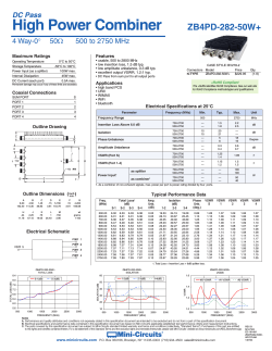
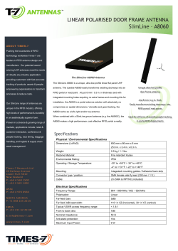


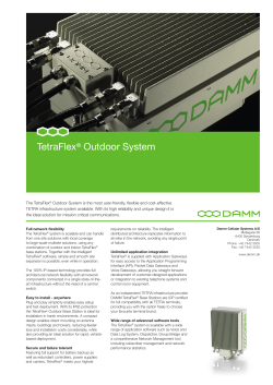
© Copyright 2026