
WaveMaster 8 Zi-B Oscilloscopes (4 GHz-30
WaveMaster 8 Zi-B Oscilloscopes 4 GHz–30 GHz Key Features • • Up to 30 GHz bandwidth and 80 GS/s sample rate of-use of a standard benchtop oscilloscope. Featuring the highest-speed interface makes configuring serial data triggers, the only complete multi-lane serial data analysis and The industry’s only true hardware 14.1 Gb/s serial pattern trigger • Low Jitter Measurement Floor and • Comprehensive set of serial data exceptional timebase stability analysis, debug, validation and compliance tools • • Integrated 50 Ω and 1 MΩ inputs • eye diagram solution, and the most comprehensive set of compliance packages, the WaveMaster 8 Zi-B simplifies the most complex testing. Exceptional Performance Advanced Waveform Processing With up to 30 GHz bandwidth, 80 GS/s A powerful PC with a 3.1 GHz quad sample rate, low noise, an extremely core processor and up to 32 GB of RAM stable time base and a 14.1 Gb/s serial enables fast waveform processing for trigger the WaveMaster 8 Zi-B has the most advanced analysis. User- the hardware performance to capture defined mathematical functions and today’s high-speed signals. measurements are available natively, for true connection and probing Most Advanced User Interface flexibility Teledyne LeCroy’s MAUI user interface or through seamless integration with external environments like MATLAB. of any oscilloscope at your fingertips. Complete Characterization, Compliance Testing and Debug Coupled with the WaveMaster 8Zi-B’s The WaveMaster 8 Zi-B provides the 15.3” high-resolution touchscreen, most powerful analysis tools. SDAIII- MAUI makes advanced analysis easy CompleteLinQ simultaneously displays crosstalk analysis to set up and use. A flat menu structure eye diagrams and breaks down jitter on Real-time de-embedding, puts the most common tools in the four signals. EyeDrII and VirtualProbe easiest reach. Sophisticated multi-grid options analyze lane interactions using displays are simple to configure. Verti- S-parameter files. Crosstalk tools cal, horizontal and acquisition setting analyze amplitude noise. QualiPHY changes are made without obscuring software simplifies and automates waveform display. compliance testing and reporting for a Integrated standard and custom measurements and math functions for unrivaled analysis capability • feature set needed for today’s high-speed measurements with the ease- Most advanced oscillscope user complex measurements easy • The WaveMaster 8 Zi-B combines the performance, signal fidelity and Multi-lane serial data eye, jitter and emulation, and equalization puts the deepest measurement toolset wide range of serial data standards. MAUI – THE MOST ADVANCED USER INTERFACE The WaveMaster 8Zi-B is a sophisticated instrument, designed for solving complex problems. But the MAUI user interface makes advanced analysis easy to set up and use. Designed for Touch Built for Simplicity Made to Solve Teledyne LeCroy’s MAUI user interface, Dialogs are intuitive, with a “flat” menu MAUI provides the most tightly-inte- along with the WaveMaster 8Zi-B’s structure that puts the most common grated toolset of any oscilloscope user 15.3” high-resolution touchscreen, puts tools in the easiest reach. Sophis- interface. Track measured parameters easy control and advanced analysis at ticated multi-grid displays are easy across acquisitions, trend their varia- your fingertips. Select measurement to configure. Vertical, horizontal and tions on longer timescales, or visualize parameters and math functions from acquisition setting changes are made and measure their distributions using touch-friendly menus. Effortlessly without obscuring waveform display. histograms. Chain multiple measure- move waveforms between grids by ments and math functions together to dragging easy-to-select descriptor easily create custom analysis features boxes. Zoom in on areas of interest for your applications. Integrate third- with the swipe of a fingertip. party programming environments like MATLAB directly into the scope’s processing stream for even more customization. 2 INTEGRATED VIEWS FOR FASTER INSIGHT Connecting a problem with its root cause often requires viewing the signal in multiple domains. The WaveMaster 8Zi-B allows you to combine multiple analysis types into a single, correlated display: • • • • • • Analog signals Protocol decodes Eye diagrams Jitter and noise breakdown Measurement parameters Frequency-domain traces Decode From Bit-level to Protocol Layer Comprehensive Physical Layer Analysis Customized Tools Decoders are available for over 20 The WaveMaster 8Zi-B has the largest toolkit for characterizing signal party programs can be completely low-speed and high-speed serial data buses. These fully-integrated analysis integrity and debugging physical layer tools annotate the acquired analog problems: waveform with the corresponding de- • SDAIII CompleteLinQ: the most com- coded data, as well as providing a comprehensive, exportable decode table. For many standards, ProtoSync allows a view from even higher up the protocol stack, linking the physical-layer waveforms to full transaction- and protocol-layer analysis. plete NRZ signal analysis package available for any oscilloscope • DDR Debug: the only toolkit specifically for validating and troubleshooting DRAM designs With the MAUI user interface, thirdintegrated into the oscilloscope’s processing stream. Create customized math functions and parameters using C/C++, MATLAB, Excel, JScript or Visual Basic without ever leaving the oscilloscope application - and view the results directly on the oscilloscope, in real-time. • Decode and physical-layer test packages for MIPI M-PHY and D-PHY • PAM4 analysis for leading-edge multilevel signal analysis 3 THE MOST CAPABLE HARDWARE PLATFORM The WaveMaster 8 Zi-B is built on an exceptionally accurate acquisition system, with pristine signal fidelity and high timebase stability. Coupled with the most flexible set of inputs and the highest-performance serial trigger, it represents the most versatile platform in its class. • Pristine high-bandwidth performance: — Up to 30 GHz bandwidth, 80 GS/s sample rate, 512 Mpts of analysis memory on 2 channels — Up to 20 GHz bandwidth, 40 GS/s sample rate, 256 Mpts of analysis memory on 4 channels • Bandwidth upgrade capability from 4 GHz to 30 GHz to maximize investment leverage • Hardware serial triggering up to 14.1 Gb/s — The highest speed true-hardware serial trigger provides capability for 80-bit NRZ serial pattern triggering, 8b/10b symbol triggering, and 64b/66b symbol triggering, at up to 14.1 Gb/s. — Teledyne LeCroy’s true hardware trigger means even infrequently-occurring patterns can be reliably triggered on and captured. Competing software “serial triggers” risk missing rare events. — A 6.5 Gb/s serial trigger is included standard with SDA 8 Zi-B models, upgradeable to 14.1 Gb/s. Either serial trigger may be added to WaveMaster 8 Zi-B and DDA 8 Zi-B models. • The WaveMaster 8 Zi-B is the only high-bandwidth oscilloscope to support both 50 Ω and 1 MΩ inputs on the same instrument without the use of cumbersome external adapters. • An exceptionally accurate and stable timebase 100fs (rms) timebase jitter - provides the best possible jitter measurement accuracy. 4 SUPERIOR ANALYSIS AND INSIGHT The WaveMaster 8 Zi-B’s MAUI advanced user interface combines the deepest toolset with simple operation, making it easy to configure sophisticated measurements. The operating software is seamlessly integrated with the hardware platform, providing the best responsiveness and ease of use in its class. • The most complete set of measurement and analysis tools in the industry leverage powerful processing capability to provide deeper insight in less time. • Intel ® Core™ i7-4770S Quad-core, 3.1 GHz (per core, up to 3.9 GHz in Turbo mode) CPU with 8 GB of RAM (upgradeable to 32 GB) • High resolution 15.3” WXGA widescreen color touch screen display. • X-Stream II streaming architecture — 10 - 100 times faster analysis and better responsiveness than other oscilloscopes • QualiPHY serial data compliance packages - speed up testing times and reduce complexity with fully automated compliance packages for PCI Express®, DDR memory, USB 3.0, and many other standards. • Crosstalk and Vertical Noise Analysis • SDAIII “LinQ” options provide four simultaneous eye diagrams and jitter calculations for multi-lane serial data link analysis, or for single-lane, multiple location analysis • Eye Doctor™ II and Virtual Probe Signal Integrity Toolsets provide real-time de-embedding, emulation, and equalization on serial data channels and complex networks • 325 MB/s data transfer rate from oscilloscope to PC with Teledyne LeCroy Serial Interface Bus (LSIB) option 5 Data er SDA8ZI-B SERIAL DATA ANALYZER Serial Data Analyzer + = WaveMaster 8 Zi-B + = + + + SDAIII Eye and Jitter Analysis + Extended Acquisition Memory High-speed Serial Triggering With its combination of high bandwidth, excellent signal fidelity, and the most complete toolset in its class, the WaveMaster 8 Zi-B is the ideal platform for high-speed serial data analysis. The SDA 8 Zi-B models have been specifically configured to handle today’s most challenging serial data applications: + + + The SDA 8 Zi-B comes standard with the SDAIII core toolset, providing tightlyintegrated and comprehensive eye diagram and jitter analysis for NRZ signals. SDAIII easily emulates complex clock recovery and PLL behavior, and quickly renders eye diagrams using all acquired unit intervals. Jitter analysis includes Rj - Dj separation, Tj extrapolation, measurements of DDJ, ISI, and Pj, and visualization using histograms, tracks, and jitter spectra. + + With 64 Mpts on all four input channels, the SDA 8Zi-B doubles the WaveMaster’s standard acquisition memory. Serial data analysis puts a particular set of demands on an oscilloscope’s timebase capabilities. Decoding up to protocol level typically requires the acquisition of long waveforms. Likewise, slowly-varying physical-layer characteristics such as SpreadSpectrum Clocking (SSC) must be analyzed over periods of milliseconds. + The SDA 8Zi-B comes standard with a true hardware high-speed serial pattern trigger, to ensure capture of even the rarest pattern at up to 6.5 Gb/s. The trigger also natively triggers on 8b/10b and 64b/66b words, with corresponding decoders included in the SDA configuration. And if 6.5 Gb/s is not enough, the high-speed serial trigger can be upgraded to an industryleading 14.1 Gb/s. 6 SPECIFIC SERIAL DATA SOLUTIONS Automated Compliance Testing Teledyne LeCroy’s QualiPHY software is the ideal solution for physical layer compliance testing, making it easy to produce a comprehensive report of test results including screenshots. QualiPHY reduces the time and effort needed to perform compliance testing on a wide array of serial standards including: Verifying DDR memory operation using an SDA8Zi-B and the DDR Debug Toolkit software package. The SDA 8Zi-B is configured specifically for testing serial data signals. With high-speed serial triggering capability and the most comprehensive analysis software, the SDA 8Zi-B is the obvious choice for the most challenging test and debug tasks: DDR Memory PCI Express® Verifying DDR memory operation is one The SDA 8Zi-A is the basis of the most of the most common challenges in complete PCI Express test solution: high-speed electronics today. The SDA 8Zi-B is the ideal platform for validating and debugging DDR implementations. • T eledyne LeCroy’s unique DDR Debug toolkit is the ultimate DDR analysis package. Perform Read/Write burst • A utomated transmitter and receiver compliance testing using QualiPHY. • The only certified solution for Link • PCI Express (1.0, 2.0, 3.0) • USB1, USB2, USB 3.0, USB 3.1 • DDR2, LPDDR2, DDR3, LPDDR3, DDR4 SAS2, SAS3, SATA MIPI D-PHY and M-PHY 10/100/100 BASE-T, 10GBASE-T, 10GBASE-KR, SFI HDMI 1.4, DisplayPort 1.2 M OST50, MOST150, BroadR-Reach • • • • • Equalization testing (required for PCI-SIG compliance) using PeRT3. • D ebug using protocol-layer decode, separation and display eye diagrams, SDAIII eye and jitter analysis, and jitter analysis, and measurements PCIe-specific measurements. specific to DDR, allowing for a quick understanding of system performance with a push of a button. • Q ualiPHY-DDR packages perform automated JEDEC compliance testing for DDR2, DDR3, DDR4, LPDDR2, and LPDDR3. • U nique probing solutions solve the challenge of probing DDR signals. PCIe Gen3 Link Equalization testing using the SDA8Zi-B and the PeRT3 Phoenix. 7 SDAIII CORE SERIAL DATA ANALYSIS TOOLKIT The Teledyne LeCroy SDAIII-CompleteLinQ Serial Data Analysis products include multilane eye and jitter analysis, LaneScape™ comparison modes, vertical noise measurements, and crosstalk analysis tools. These capabilities provide the deepest insight into the behavior of multi- or single-lane serial data systems. SDAIII Core Toolset Teledyne LeCroy provides the most complete toolset in the industry for jitter measurements and eye diagram/jitter analysis. Rj and Dj are separated and Dj is decomposed using one of three dual-dirac algorithms. Eye diagrams containing all acquired unit intervals are rendered 10-100x faster than competitive systems. Eye diagram analysis tools, such as the extrapolated IsoBER plot, aid insight. Multiple additional tools, such as Tracks, Histograms, and Spectrum waveforms, enhance the understanding of jitter causes. Sophisticated pattern analysis tools like Intersymbol Interference (ISI) measurements and plots provide deep insight into Data Dependent Jitter (DDj) behavior. Data Rate Configuration Chart Standard PCI Express Gen1 InfiniBand Serial Rapid I/O DisplayPort 1.1 SAS Gen1 Serial Rapid I/O XAUI HDMI 1.4 SATA Gen2 DDR4 Fibre Channel 4GFC Serial Rapid I/O InfiniBand PCI Express Gen2 PCI Express Gen3 Serial Rapid I/O USB 3.0 DisplayPort 1.2 GDDR5 SAS Gen2 SATA Gen3 Serial Rapid I/O QPI (Quick Path Interconnect) USB 3.1 10GBase-KR SFI/SFP+ CEI-11 SAS12 InfiniBand CEI-25/28 8 Bit Rate 2.5 Gb/s 2.5 Gb/s 2.5 Gb/s 2.7 Gb/s 3 Gb/s 3.125 Gb/s 3.125 Gb/s 3.4 Gb/s 3 Gb/s 4 GT/s 4.25 Gb/s 4.25 Gb/s 5 Gb/s 5 Gb/s 8 Gb/s 5 Gb/s 5 Gb/s 5.4 Gb/s 6 Gb/s 6 Gb/s 6 Gb/s 6.25 Gb/s 6.4 Gb/s 10 Gb/s 10.3125 Gb/s 10.3125 Gb/s 11 Gbps 12 Gb/s 25.78125 Gb/s 25–28 Gb/s Minimum Bandwidth Recommended Oscilloscope 6 GHz SDA 806Zi-B or Above 8 GHz SDA 808Zi-B or Above 10 GHz 13 GHz SDA 813Zi-B or Above 16 GHz SDA 816Zi-B or Above 20 GHz SDA 820Zi-B or Above 25 GHz SDA 825Zi-B or Above 30 to 100 GHz SDA 830Zi-B, LabMaster 9 Zi-B or LabMaster 10 Zi up to 100 GHz SDAIII UPGRADES AND SDAIII-COMPLETELINQ Measure up to 4 Lanes Simultaneously “LinQ” products provide extensive multi-lane analysis capabilities. Quickly understand lane-to-lane differences in jitter measurements, eye diagrams, and jitter analysis. Perform aggressor on/off analysis, and see the results from both scenarios simultaneously. Save the analysis of a particular scenario to the Reference Lane, and configure a LaneScape™ Comparison mode to compare the Reference to either one, two or all lanes. Each “lane” can be a different serial data lane, or a different analysis of data from a single serial data lane - ideal for comparing different equalization schemes (using Eye Doctor II option) or examining system behaviors at different locations in the link (using probes or the VirtualProbe option). Vertical Noise and Crosstalk The Crosstalk and CrossLinQ packages provide vertical noise measurements and crosstalk analysis tools for complete aggressor/victim analysis. Use one of three dualDirac models to measure and separate noise into total (Tn), random (Rn) and deterministic (Dn) components, and further decompose Dn into Intersymbol Interference Noise (ISIn) and Periodic Noise (Pn). Only Teledyne LeCroy performs this analysis on real-time oscilloscopes. Similar to jitter analysis, noise can be viewed as a noise track, histogram and spectrum, providing insight into the vertical noise resulting from coupling to other active serial data lanes or other interference sources. The Crosstalk Eye shows the probabilistic extent of noise both inside and outside the eye, quickly showing the impact of excessive noise that is not possible to see in a traditional eye diagram. Learn More: teledynelecroy.com /SDAIII CompleteLinQ Does it All The CompleteLinQ user interface framework provides easy access to all features described above, and also integrates EyeDoctorII and VirtualProbe capabilities for Tx/Rx equalization and fixture/channel de-embedding/emulation. Order SDAIIICompleteLinQ to equip your oscilloscope with all of Teledyne LeCroy’s Serial Data Analysis and Signal Integrity tools. 9 ADVANCED SERIAL DATA AND SIGNAL INTEGRITY TOOLS PAM4 Signal Analysis Teledyne LeCroy’s PAM4 analysis package builds on SDAIII’s industry-leading eye, jitter and noise analysis technology to perform a complete analysis of all three eye openings in a PAM4 signal. Measurements for each opening include: Eye Height, Width Tj, Rj, Dj, Tn, Rn and Dn. Mean and RMS vales for each level are also determined, as well as periodic noise and jitter results. Enhance understanding of PAM4 signal behavior by displaying histograms, spectra, bathtub and IsoBER curves for each eye opening. PAM4 analysis is compatible with EyeDoctorII, allowing users to de-embed channel and fixture effects, emulate a channel, or apply equalization. Advanced Signal Integrity Tools EyeDoctorII VirtualProbe Many high-speed measurements require removing the effects of a fixture, applying a channel model, and emulating the operation of a receiver equalizer on an acquired signal. The EyeDoctorII package includes easy configuration of basic de-embed/emulation scenarios, CTLE, DFE and FFE equal- The VirtualProbe package expands the capabilities of EyeDoctorII. Configure a multi-block circuit using S-parameters, and VirtualProbe will display the signal as it would appear before or after any block in the circuit. The electrical behavior of a block to reflect and transmit signals can be included, added or removed. Probe loading effects can also be removed. izers, and transmitter emphasis/de-emphasis. VirtualProbe shows you the signal where the probe is not located: TRANSMITTER 1 2 3 4 Fixture Backplane Connector Trace RECEIVER 1 Virtually probe the signal at the transmitter with the fixture present, and then de-embed its effects form the measurement. 10 View the signal between structures to understand losses, ISI and crosstalk caused by backplanes, interconnects and connectors. See what the eye looks like at the receiver - even if it is not in reach of a differential probe. 2 3 4 Use EyeDoctor to open the eye by modeling CTLE, FFE and DFE equalizers used by your receiver. A COMPLETE SERIAL DATA TEST SUITE Modern high-speed electronics test demands a set of instruments that goes beyond the oscilloscope, for applications such as receiver tolerance testing and interconnect characterization. Teledyne LeCroy addresses these challenges with innovative instruments which are both powerful and easy to use, simplifying test and reducing time-to-market. PeRT3 Phoenix – Protocol Enabled Receiver and Transmitter Tolerance Tester Modern serial data standards such as PCI Express 3.0 require negotiation of equalization parameters to ensure interoperability. Truly testing a receiver’s operation demands an instrument which perform more than just the basic BERT functions of pattern generation and error detection. Teledyne LeCroy’s PeRT3 is the industry’s first Protocol-enabled Receiver Tester, a totally new class of instrument designed to overcome these difficult test challenges. The combination of the PeRT3 and the SDA 8Zi-B represents the most complete serial data test system available. SPARQ Signal Integrity Network Analyzer The SPARQ series of signal integrity network analyzers make S-parameter measurements on up to 12 ports and to 30 GHz (40 GHz for 4 port models). SPARQ uses the industry’s only built-in and automatic OSLT calibration methodology. Users simply connect their SPARQ to their DUT and their PC to the SPARQ via USB. When making a measurement, the OSLT calibration proceeds automatically and without any requirement for the user intervention for the calibration or to switch the connections to the DUT. This “hands-off” approach allows high-frequency S-parameters to be measured by any engineer and without the need for “VNA expertise”. SPARQ is the ideal instrument for characterizing multi-port interconnects common in signal integrity applications at a fraction of the cost of traditional methods. With 8 and 12 port SPARQs, measurements can be made for less cost than a similar 4-port VNA, allowing users to easily and quickly make crosstalk measurements on 2 or 3 lane interconnects. 11 WAVELINK PROBE SYSTEMS WaveLink High Bandwidth Differential Probes Ultra-wideband Architecture with Superior Signal Fidelity Teledyne LeCroy’s WaveLink® high bandwidth differential probes utilize advanced amplifier architecture to achieve superior analog broadband performance. Exceptional noise characteristics mean the combination of the probe and the oscilloscope results in measurement performance that is nearly identical to that of a cable input. Versatile High Bandwidth Probe Tips up to 25 GHz Solder-In tips with 25 GHz bandwidth and system (probe + oscilloscope) rise times equal to that of the oscilloscope alone. The most compact positioner tip browser with bandwidth up to 22 GHz makes probing in confined areas easy. Superior Probe Impedance Minimizes Circuit Loading Circuit and signal loading is reduced by more than 50% compared to competitive probes. In the mid-band frequency range, the difference is even more apparent. D2505-A-PS 25 GHz probe system with Solder-In lead and browser positioner tip. Bandwidth Rise Time (10–90%) Rise Time (20–80%) Noise (Probe) D1305-A-PS D1605-A-PS D2005-A-PS D2505-A-PS Dxx05-SI and Dxx05-PT Tips 13 GHz Dxx05-SI and Dxx05-PT Tips 16 GHz Dxx05-SI and Dxx05-PT Tips 20 GHz Dxx05-SI Lead 25 GHz Dxx05-SI and Dxx05-PT Tips 32.5 ps (typical) Dxx05-SI and Dxx05-PT Tips 28 ps (typical) Dxx05-SI and Dxx05-PT Tips 20 ps (typical) Dxx05-SI and Dxx05-PT Tips 24.5 ps (typical) Dxx05-SI and Dxx05-PT Tips 21 ps (typical) Dxx05-SI and Dxx05-PT Tips 15 ps (typical) < 14 nV/√Hz (1.6 mVrms) (typical) Input Dynamic Range Input Common Mode Voltage Range Input Offset Voltage Range Impedance (mid-band, typical) < 14 nV/√Hz < 18 nV/√Hz (1.8 mVrms) (2.5 mVrms) (typical) (typical) 2.0 Vpk-pk, (±1.0 V) (nominal) ±4 V (nominal) Dxx05-PT Tip 22 GHz typical 20 GHz guaranteed Dxx05-SI Lead 17.5 ps (typical) Dxx05-PT Tip 19 ps (typical) Dxx05-SI Lead 13 ps (typical) Dxx05-PT Tip 14 ps (typical) < 18 nV/√Hz (2.8 mVrms) (typical) ±2.5 V Differential (nominal) Dxx05-SI Lead: 300 Ω at 6 GHz, 525 Ω at 13 GHz, 600 Ω at 16 GHz, 300 Ω at 20 GHz, 120 Ω at 25 GHz Dxx05-PT Tip: 160 Ω at 6 GHz, 450 Ω at 13 GHz, 240 Ω at 16 GHz, 210 Ω at 20 GHz Other WaveLink Probing Solutions With bandwdiths from 4 GHz to 13 GHz, wide input dynamic range, exceptionally low loading and versatile tip selections, the Medium- and L:ow Bandwidth WaveLink Differential Probe Systems are ideal for many applications - including the oftenchallenging probing of DDR memory signals. WaveLink Low Bandwidth Differential Probes • 4 and 6 GHz models • Solder-In, Browser, Quick Connect, Square Pin, Positioner Tip and HiTemp Cables 12 WaveLink Medium Bandwidth Differential Probes • 8, 10, and 13 GHz models • 3.5 V Input Dynamic Range • ±4 V Offset • Solder-in, Positioner (Browser), p-p Square Pin, and SMA/SMP lead connection BROAD RANGE OF PROBING SOLUTIONS WaveMaster 8 Zi-B oscilloscopes support a broad range of probes for a variety of applications. ZS Series High Impedance Active Probes ZD Series Differential Probes • 1 GHz (ZS1000), 1.5 GHz • 200 MHz, 500 MHz, 1 GHz (ZS1500) and 2.5 GHz (ZS2500) bandwidths and 1.5 GHz bandwidths • Wide range of probing • High Impedance (0.9 pF, 1 MΩ) • Extensive standard and accessories • Teledyne LeCroy ProBus vailable probe tip and ground a connection accessories system • ±12 Vdc offset (ZS1500) • Teledyne LeCroy ProBus system High-Voltage Differential Probes • 20 MHz and 100 MHz High-Voltage Passive Probes • Suitable for safe, accurate bandwidth • 1,000 V common mode voltage high-voltage measurements • Fixed-attenuation probes • 1,400 V covering a range from 1 kV to 6 kV and varying transient overvoltage ratings voltage • Works with any 1 MΩ input oscilloscope Current Probes • Range of probes from 30 A rms (50 Apeak) to 500 Arms (700 Apeak) • 2 MHz to 100 MHz bandwidths • Small form factor accommo• rms peak differential • EN 61010 CAT III • 80 dB CMRR at 50/60 Hz • Teledyne LeCroy ProBus system Optical-to-Electrical Converter (OE695G) • Frequency range DC to 9.5 GHz (electrical, -3 dB) • Reference receiver support dates large conductors with small jaw size from 8GFC to 10GFC FEC, or Custom (<12.5 Gb/s) eledyne LeCroy ProBus T system • 62.5/125 µm multi-mode or single-mode fiber input • Broad wavelength range (750 to 1650 nm) • +7 dBm (5 mW) max peak optical power • Low noise (as low as 25 pW/√Hz) Mixed Signal Oscilloscope Option (MS-250/MS-500) The Mixed Signal options allow the WaveMaster 8 Zi-B to operate as a mixed signal oscilloscope with up to 36 digital channels with 2 GS/s digital sample rate and 50 Mpts/Ch. 13 SPECIFICATIONS Vertical System Analog Bandwidth @ 50 Ω (-3 dB) (ProLink Input) Analog Bandwidth @ 50 Ω (-3 dB) (ProBus Input) Analog Bandwidth @ 1 MΩ (-3 dB) (ProBus Input) Rise Time (10–90%, 50 Ω) Rise Time (20–80%, 50 Ω) Input Channels Bandwidth Limiters 14 WaveMaster 804Zi-B (SDA) WaveMaster 806Zi-B (SDA) WaveMaster 808Zi-B (SDA/DDA) WaveMaster 813Zi-B (SDA) 4 GHz (≥ 10 mV/div) 6 GHz (≥ 10 mV/div) 8 GHz (≥ 10 mV/div) 13 GHz (≥ 10 mV/div) 3.5 GHz (≥ 10 mV/div) 3.5 GHz (≥ 10 mV/div) 3.5 GHz (≥ 10 mV/div) 3.5 GHz (≥ 10 mV/div) 63 ps (test limit, flatness mode) 47 ps (flatness mode) 49 ps (test limit, flatness mode) 37 ps (flatness mode) 32.5 ps (test limit, flatness mode) 24.5 ps (flatness mode) 20 MHz, 200 MHz, 1 GHz, 4 GHz, 6 GHz 20 MHz, 200 MHz, 1 GHz, 4 GHz, 6 GHz, 8 GHz 500 MHz (typical, ≥ 2 mV/div) 95 ps (test limit, flatness mode) 71 ps (flatness mode) 4 (Any combination of ProLink and ProBus inputs) 20 MHz, 200 MHz, 1 GHz 20 MHz, 200 MHz, 1 GHz, 4 GHz Input Impedance ProLink Inputs: 50 Ω ±2% for ≤ 100 mV/div, 50 Ω ±3% for > 100 mV/div ProBus Inputs: 50 Ω ±2% or 1 MΩ || 16 pF, 10 MΩ || 11 pF with supplied Probe Input Coupling ProLink Inputs: 50 Ω: DC, GND ProBus Inputs: 1 MΩ: AC, DC, GND; 50 Ω: DC, GND Maximum Input Voltage 50 Ω (ProLink): ±2 V max. @ ≤ 100 mV/div, 5.5 Vrms @ > 100 mV/div 50 Ω (ProBus): ±5 V max., 3.5 Vrms 1 MΩ (ProBus): 250 V max. (peak AC: < 10 kHz + DC) Channel-Channel Isolation DC to 10 GHz: 50 dB (> 315:1) 0 to 15 GHz: 46 dB (> 200:1) 1 15 to 20 GHz: 40 dB (> 100:1) (For any two ProLink input channels, same or different v/div settings, typical) Vertical Resolution 8 bits up to 11 bits with enhanced resolution (ERES) SPECIFICATIONS WaveMaster 816Zi-B (SDA) Vertical System WaveMaster 820Zi-B (SDA, DDA) Analog Bandwidth @ 50 Ω (-3 dB) (2.92 mm input) Analog Bandwidth @ 50 Ω (-3 dB) (ProLink Input) Analog Bandwidth @ 50 Ω (-3 dB) (ProBus Input) Analog Bandwidth @ 1 MΩ (-3 dB) (ProBus Input) Rise Time (10–90%, 50 Ω) Bandwidth Limiters Input Impedance Input Coupling Maximum Input Voltage WaveMaster 830Zi-B (SDA, DDA) 25 GHz 30 GHz 16 GHz (≥ 10 mV/div) 20 GHz (≥ 10 mV/div) 20 GHz (≥ 10 mV/div) 20 GHz (≥ 10 mV/div) 3.5 GHz (≥ 10 mV/div) 3.5 GHz (≥ 10 mV/div) 3.5 GHz (≥ 10 mV/div) 3.5 GHz (≥ 10 mV/div) 22 ps (test limit, flatness mode) 16.5 ps (flatness mode) 17.5 ps (test limit, flatness mode) 13 ps (flatness mode) 15.5 ps (test limit, flatness mode) 11.5 ps (flatness mode) 500 MHz (typical, ≥ 2 mV/div) 28.5 ps (test limit, flatness mode) 21.5 ps (flatness mode) Rise Time (20–80%, 50 Ω) Input Channels WaveMaster 825Zi-B (SDA) 4 (Any combination of ProLink and ProBus inputs) 4 (Any combination of 20 GHz ProLink inputs or 3.5 GHz ProBus inputs), 3 (1 @ full BW, 2 with ProLink or ProBus input), or 2 (@ full BW) 40 GS/s mode: 20 MHz, 40 GS/s mode: 20 MHz, For ≤ 20 GHz Mode: For ≤ 20 GHz Mode: 200 MHz, 1 GHz, 4 GHz, 6 GHz, 200 MHz, 1 GHz, 4 GHz, 6 GHz, 20 MHz, 200 MHz, 1 GHz, 20 MHz, 200 MHz, 1 GHz, 8 GHz, 13 GHz 8 GHz, 13 GHz, 16 GHz 4 GHz, 6 GHz, 8 GHz, 4 GHz, 6 GHz, 8 GHz, 13 GHz, 16 GHz 13 GHz, 16 GHz 80 GS/s Mode: 13 GHz 80 GS/s Mode: 13 GHz, 16 GHz For > 20 GHz Mode: 20 GHz For > 20 GHz Mode: 20 GHz, 25 GHz ProLink Inputs: 2.92 mm Inputs: 50 Ω ±2% for ≤ 100 mV/div, 50 Ω ±3% for > 100 mV/div 50 Ω ±2% for ≤ 79 mV/div, 50 Ω ±3% for > 79 mV/div ProBus Inputs: ProLink Inputs: 50 Ω ±2% or 1 MΩ || 16 pF, 10 MΩ || 11 pF with supplied Probe 50 Ω ±2% for ≤ 100 mV/div, 50 Ω ±3% for > 100 mV/div ProBus Inputs: 50 Ω ±2% or 1 MΩ || 16 pF, 10 MΩ || 11 pF with supplied Probe ProLink Inputs: 2.92 mm Inputs: 50 Ω: DC, GND 50 Ω: DC, GND ProBus Inputs: ProLink Inputs: 1 MΩ: AC, DC, GND; 50 Ω: DC, GND 50 Ω: DC, GND ProBus Inputs: 1 MΩ: AC, DC, GND; 50 Ω: DC, GND 50 Ω (ProLink): 2.92 mm Inputs: ±2 V max. @ ≤ 100 mV/div, 5.5 Vrms @ > 100 mV/div ±2 Vmax @ ≤ 100 mV/div, 5.5 Vrms @ > 100 mV/div 50 Ω (ProBus): 50 Ω (ProLink): ±5 V max., 3.5 Vrms ±2 Vmax @ ≤ 100 mV/div, 5.5 Vrms @ > 100 mV/div 1 MΩ (ProBus): 50 Ω (ProBus): 250 V max. (peak AC: < 10 kHz + DC) ±5 Vmax, 3.5 Vrms 1 MΩ (ProBus): 250 Vmax (peak AC: < 10 kHz + DC) DC to 10 GHz: 50 dB (> 315:1) 10 to 15 GHz: 46 dB (> 200:1) 15 to 20 GHz: 40 dB (> 100:1) (For any two ProLink input channels, same or different v/div settings, typical) Channel-Channel Isolation Vertical Resolution 8 bits up to 11 bits with enhanced resolution (ERES) DC to 10 GHz: 50 dB (> 315:1) 10 to 15 GHz: 46 dB (> 200:1) 15 to 20 GHz: 40 dB (> 100:1) 20 GHz to Max BW: 30 dB (> 32:1) (For any two ProLink or 2.92 mm input channels, same or different v/div settings, typical) 15 SPECIFICATIONS Vertical System (cont’d) Sensitivity WaveMaster 804Zi-B (SDA) WaveMaster 806Zi-B (SDA) WaveMaster 808Zi-B (SDA/DDA) WaveMaster 813Zi-B (SDA) 50 Ω (ProLink): 2 mV–1 V/div, fully variable (2–9.9 mV/div via zoom) 50 Ω (ProBus): 2 mV–1 V/div, fully variable 1 MΩ (ProBus): 2 mV–10 V/div, fully variable DC Vertical Gain Accuracy ±1% F.S. (typical), offset at 0 V; ±1.5% F.S. (test limit), offset at 0 V (Gain Component of DC Accuracy) Vertical Noise Floor 0.75 mVrms 0.93 mVrms (50 mV/div) (typical) (typical) Offset Range 50 Ω (ProLink): ±500 mV @ 2–100 mV/div ±4 V @ > 100 mV/div–1 V/div 50 Ω (ProBus): ±750 mV @ 2–100 mV/div ±4 V @ > 100 mV/div–1 V/div 1 MΩ: ±1 V @ 2–140 mV/div ±10 V @ 142 mV–1.40 V/div ±100 V @ 1.42 V–10 V/div 1.05 mVrms (typical) 1.21 mVrms (typical) DC Vertical Offset Accuracy ±(1.5% of offset setting + 1.5% F.S. + 1 mV) (test limit) Horizontal System Timebases Time/Division Range Clock Accuracy Sample Clock Jitter Delta Time Measurement Accuracy Jitter Measurement Floor Internal time base common to 4 input channels 20 ps/div–128 s/div, depending on memory length Real-time Mode: 20 ps/div–64 s/div; RIS Mode: 20 ps/div–10 ns/div; user selectable at ≤ 10 ns/div; Roll Mode: 100 ms/div up to 128 s/div, user selectable at ≥ 100 ms/div and ≤ 5 MS/s Noise 2 Noise 2 + (Sample Clock Jitterrms ) 2 SlewRate < 1 ppm + (aging of 0.5 ppm/yr from last calibration) Up to 10μs Acquired Time Range: 100 fsrms (Internal Timebase Reference) Up to 6.4ms Acquired Time Range: 150 fsrms (Internal Timebase Reference) 2* SlewRate Noise SlewRate Jitter Between Channels (TIE, typical, measured at maximum bandwidth) Trigger and Interpolator Jitter Channel-Channel Deskew Range External Time base Reference (Input) External Time base Reference (Output) 16 <500 fsrms 2 + (Sample Clock Jitterrms ) 2 + (clock accuracy * reading) + (Sample Clock Jitterrms ) 2 <450 fsrms <425 fsrms 2 Noise < 0.1 psrms (typical, software+assisted), 2 psrms (typical, hardware) 2* (Sample Clock Jitterrms ) 2 + (clock accuracy * reading) SlewRate ±9 x time/div. setting or 25 ns max. (whichever is larger), each channel 10 MHz; 50 Ω impedance, applied at the rear input 10 MHz; 50 Ω impedance, output at the rear <325 fsrms SPECIFICATIONS Vertical System (cont’d) Sensitivity WaveMaster 816Zi-B (SDA) WaveMaster 820Zi-B (SDA, DDA) WaveMaster 825Zi-B (SDA) 50 Ω (ProLink) at 40 GS/s: 2 mV–1 V/div, fully variable (2-9.9 mV/div via zoom) 50 Ω (ProLink) at 80 GS/s: 2 mV–1 V/div, fully variable (2-19.9 mV/div via zoom) 50 Ω (ProBus): 2 mV–1 V/div, fully variable 1 MΩ (ProBus): 2 mV–10 V/div, fully variable WaveMaster 830Zi-B (SDA, DDA) 50 Ω (2.92 mm): 10 mV–500 mV/div, fully variable 50 Ω (ProLink): 2 mV–1 V/div, fully variable (2–9.9 mV/div via zoom) 50 Ω (ProBus): 2 mV–1 V/div, fully variable 1 MΩ (ProBus) 2 mV–10 V/div, fully variable DC Vertical Gain Accuracy ±1% F.S. (typical), offset at 0 V; ±1.5% F.S. (test limit), offset at 0 V (Gain Component of DC Accuracy) Vertical Noise Floor 1.28 mVrms 1.44 mVrms (50 mV/div) (typical) (typical) Offset Range 50 Ω (ProLink): ±500 mV @ 2–100 mV/div ±4 V @ > 100 mV/div–1 V/div 50 Ω (ProBus): ±750 mV @ 2–100 mV/div ±4 V @ > 100 mV/div–1 V/div 1 MΩ: ±1 V @ 2–140 mV/div ±10 V @ 142 mV–1.40 V/div ±100 V @ 1.42 V–10 V/div 2.80 mVrms (typical) 2.90 mVrms (typical) 50 Ω (2.92 mm): ±500 mV @ 10–79 mV/div ±4 V @ 80 mV/div–500 mV/div 50 Ω (ProLink): ±500 mV @ 2–100 mV/div ±4 V @ >100 mV/div–1 V/div 50 Ω (ProBus): ±750 mV @ 2–100 mV/div ±4 V @ >100 mV/div–1 V/div 1 MΩ: ±1 V @ 2–128 mV/div ±10 V @ 130 mV–1.28 V/div ±100 V @ 1.3 V–10 V/div DC Vertical Offset Accuracy ±(1.5% of offset setting + 1.5% F.S. + 1 mV) (test limit) Horizontal System Timebases Time/Division Range Internal time base common to 4 input channels Real-time Mode at 80 GS/s: 20 ps/div–640 µs/div, depending on memory length Real-time Mode at other sample rates: 20 ps/div–128 s/div, depending on memory length Real-time Mode: 20 ps/div–64 s/div; RIS Mode: 20 ps/div–10 ns/div; user selectable at ≤ 10 ns/div; Roll Mode: 100 ms/div up to 128 s/div, user selectable at ≥ 100 2 Noisems/div and(Sample ≤ 5 MS/s + Clock Jitter ) 2 rms Clock Accuracy Sample Clock Jitter Delta Time Measurement Accuracy Jitter Measurement Floor SlewRate < 1 ppm + (aging of 0.5 ppm/yr from last calibration) Up to 10μs Acquired Time Range: 100 fsrms (Internal Timebase Reference) Up to 6.4ms Acquired Time Range: 150 fsrms (Internal Timebase Reference) 2* Noise 2 SlewRate Noise SlewRate Jitter Between Channels (TIE, typical, measured at maximum bandwidth) Trigger and Interpolator Jitter Channel-Channel Deskew Range External Time base Reference (Input) External Time base Reference (Output) For ≥ 25 GHz Mode: Real-time Mode: 20 ps/div–640 µs/div, depending on memory length For ≤ 20 GHz Mode: 20 ps/div–128 s/div, depending on memory length Real-time Mode: 20 ps/div–64 s/div; RIS Mode: 20 ps/div–10 ns/div, user selectable at ≤10 ns/div; Roll Mode: 100 ms/div up to 128 s/div, user selectable at ≥ 100 ms/div and ≤ 5 MS/s 2 + (Sample Clock Jitterrms ) 2 + (clock accuracy * reading) + (Sample Clock Jitterrms ) 2 <300 fsrms <250 fsrms 2 Noise < 0.1 psrms (typical, software+assisted), 2 psrms (typical, hardware) 2* (Sample Clock Jitterrms ) 2 + (clock accuracy * reading) SlewRate ±9 x time/div. setting or 25 ns max. (whichever is larger), each channel 10 MHz; 50 Ω impedance, applied at the rear input 10 MHz; 50 Ω impedance, output at the rear 17 SPECIFICATIONS WaveMaster 804Zi-B (SDA) Acquisition System WaveMaster 806Zi-B (SDA) WaveMaster 808Zi-B (SDA/DDA) Single-Shot Sample Rate/Ch 40 GS/s on 4 Ch (80 GS/s on 2 Ch using optional WM8Zi-2X80GS External Interleaving Device) Random Interleaved Sampling (RIS) 200 GS/s for repetitive signals (20 ps/div to 10 ns/div) Maximum Trigger Rate Intersegment Time Maximum Acquisition Memory Standard Memory 1,000,000 waveforms/second (in Sequence Mode, up to 4 channels) 1 µs 256 Mpts/Ch WaveMaster 813Zi-B (SDA) 32 Mpts, 5,000 segments max (64 Mpts, 15,000 segments max) (Memory and Sample Rate can be doubled in 1 or 2 Ch mode with use of WM8Zi-2X80GS External Interleaving Device) Memory Options Option Mem/Ch Max Segments M-64 64 Mpts 15,000 L-128 128 Mpts 15,000 VL-256 256 Mpts 15,000 (Memory and Sample Rate can be doubled in 1 or 2 Ch mode with use of WM8Zi-2X80GS External Interleaving Device) Acquisition Processing Averaging Enhanced Resolution (ERES) Envelope (Extrema) Interpolation Summed averaging to 1 million sweeps continuous averaging to 1 million sweeps From 8.5 to 11 bits vertical resolution Envelope, floor, or roof for up to 1 million sweeps Linear or Sin x/x Triggering System Modes Sources Coupling Mode Pre-trigger Delay Post-trigger Delay Hold-off by Time or Events Internal Trigger Range ±4.1 div from center Trigger Sensitivity with Edge Trigger 2.92mm Inputs Not Applicable Trigger Sensitivity with Edge Trigger (Ch 1–4) ProBus Inputs 2 div @ < 3.5 GHz 1.5 div @ < 1.75 GHz 1.0 div @ < 200 MHz (for DC coupling, ≥ 10 mV/div, 50 Ω) 2 div @ < 4 GHz, 2 div @ < 6 GHz 1.5 div @ < 3 GHz, 1.5 div @ < 3 GHz 1.0 div @ < 200 MHz, 1.0 div @ < 200 MHz (for DC, AC, (for DC, AC, LFRej coupling, LFRej coupling, ≥ 10 mV/div, 50 Ω) ≥ 10 mV/div, 50 Ω) Trigger Sensitivity with Edge Trigger (Ch 1–4) ProLink Inputs 18 Normal, Auto, Single, and Stop Any input channel, Aux, Aux/10, Line, or Fast Edge. Slope and level unique to each source (except line trigger) DC, AC, HFRej, LFRej 0–100% of memory size (adjustable in 1% increments of 100 ns) 0–10,000 divisions in real time mode, limited at slower time/div settings or in roll mode From 2 ns up to 20 s or from 1 to 99,999,999 events 2 div @ < 8 GHz 1.5 div @ < 3 GHz 1.0 div @ < 200 MHz (for DC, AC, LFRej coupling, ≥ 10 mV/div, 50 Ω) 3 div @ < 13 GHz 1.5 div @ < 3 GHz 1.0 div @ < 200 MHz (for DC, AC, LFRej coupling, ≥ 10 mV/div, 50 Ω) SPECIFICATIONS Acquisition System Single-Shot Sample Rate/Ch Random Interleaved Sampling (RIS) Maximum Trigger Rate Intersegment Time Maximum Acquisition Memory Standard Memory WaveMaster 816Zi-B (SDA) WaveMaster 820Zi-B (SDA, DDA) WaveMaster 825Zi-B (SDA) 40 GS/s on 4 Ch 80 GS/s on 2 Ch 200 GS/s for repetitive signals (20 ps/div to 10 ns/div) 40 GS/s on 4 Ch (80 GS/s on 2 Ch when operated in ≥ 25 GHz Mode) For ≥ 25 GHz Mode: Not applicable For < 25 GHz Mode: 200 GS/s for repetitive signals (20 ps/div to 10 ns/div) 1,000,000 waveforms/second (in Sequence Mode, up to 4 channels) 1 µs 512 Mpts/Ch (2 Ch operation) 512 Mpts/Ch (2 Ch operation) 4 channels: 32 Mpts, 5,000 segments max (64 Mpts, 15,000 segments max) 2 channels: 64 Mpts, 15,000 segments max (128 Mpts, 15,000 segments max) Memory Options 4 channels: 20 Mpts, 4,500 segments max (40 Mpts, 5,000 segments max) 2 channels: 40 Mpts, 3,000 segments max (64 Mpts, 5,000 segments max) Option Mem/Ch Max Segments M-64 64 Mpts 15,000 Option L-128 128 Mpts 15,000 15,000 VL-256 256 Mpts WaveMaster 830Zi-B (SDA, DDA) 4 channels 2 channels Mem/Ch Max Segments Mem/Ch Max Segments M-64 64 Mpts 15,000 128 Mpts 10,000 L-128 128 Mpts 15,000 256 Mpts 15,000 VL-256 256 Mpts 15,000 512 Mpts 15,000 Acquisition Processing Averaging Enhanced Resolution (ERES) Envelope (Extrema) Interpolation Summed averaging to 1 million sweeps continuous averaging to 1 million sweeps From 8.5 to 11 bits vertical resolution Envelope, floor, or roof for up to 1 million sweeps Linear or Sin x/x Triggering System Modes Sources Coupling Mode Pre-trigger Delay Post-trigger Delay Hold-off by Time or Events Internal Trigger Range Trigger Sensitivity with Edge Trigger 2.92mm Inputs Normal, Auto, Single, and Stop Any input channel, Aux, Aux/10, Line, or Fast Edge. Slope and level unique to each source (except line trigger) DC, AC, HFRej, LFRej 0–100% of memory size (adjustable in 1% increments of 100 ns) 0–10,000 divisions in real time mode, limited at slower time/div settings or in roll mode From 2 ns up to 20 s or from 1 to 99,999,999 events Trigger Sensitivity with Edge Trigger (Ch 1–4) ProBus Inputs 2 div @ < 3.5 GHz 1.5 div @ < 1.75 GHz 1.0 div @ < 200 MHz (for DC coupling,≥ 10 mV/div, 50 Ω) 3 div @ < 13 GHz 1.5 div @ < 3 GHz 1.0 div @ < 200 MHz (for DC, AC, LFRej coupling, ≥ 10 mV/div, 50 Ω) Trigger Sensitivity with Edge Trigger (Ch 1–4) ProLink Inputs ±4.1 div from center Not Applicable 3 div @ < 15 GHz 1.5 div @ < 3 GHz 1.0 div @ < 200 MHz (for DC coupling, ≥ 10 mV/div, 50 Ω) 3 div @ < 15 GHz 1.5 div @ < 3 GHz 1.0 div @< 200 MHz (for DC, AC, LFRej coupling, ≥ 10 mV/div, 50 Ω) 19 SPECIFICATIONS Triggering System (cont’d) WaveMaster 804Zi-B (SDA) WaveMaster 806Zi-B (SDA) External Trigger 2 div @ < 1 GHz Sensitivity (Edge Trigger) 1.5 div @ < 500 MHz 1.0 div @ < 200 MHz (for DC, coupling) Max. Trigger Frequency, 2.0 GHz @ ≥ 10 mV/div (minimum triggerable width 200 ps) SMART Trigger External Trigger Aux (±0.4 V); Aux/10 (±4 V) Input Range Basic Triggers Edge Window TV-Composite Video SMART Triggers™ State or Edge Qualified Qualified First Dropout Pattern WaveMaster 808Zi-B (SDA/DDA) WaveMaster 813Zi-B (SDA) Triggers when signal meets slope (positive, negative, or either) and level condition Triggers when signal exits a window defined by adjustable thresholds Triggers NTSC or PAL with selectable line and field HDTV (720p, 1080i, 1080p) with selectable frame rate (50 or 60 Hz) and Line or CUSTOM with selectable Fields (1–8), Lines (up to 2000), Frame Rates (25, 30, 50, or 60 Hz), Interlacing (1:1, 2:1, 4:1, 8:1), or Synch Pulse Slope (Positive or Negative) Triggers on any input source only if a defined state or edge occurred on another input source. Holdoff between sources is electable by time or events s In Sequence acquisition mode, triggers repeatably on event B only if a defined pattern, state, or edge (event A) is satisfied in the first segment of the acquisition. Holdoff between sources is selectable by time or events Triggers if signal drops out for longer than selected time between 1 ns and 20 s Logic combination (AND, NAND, OR, NOR) of 5 inputs (4 channels and external trigger input). Each source can be high, low, or don’t care. The High and Low level can be selected independently. Triggers at start or end of the pattern SMART Triggers with Exclusion Technology Glitch Width (Signal or Pattern) Interval (Signal or Pattern) Timeout (State/Edge Qualified) Runt Slew Rate Exclusion Triggering riggers on positive or negative glitches with widths selectable as low as 200 ps to 20 s, or on intermittent faults T Triggers on positive, negative, or both widths with widths selectable as low as 200 ps to 20 s, or on intermittent faults Triggers on intervals selectable between 1 ns and 20 s Triggers on any source if a given state (or transition edge) has occurred on another source. Holdoff between sources is 1 ns to 20 s, or 1 to 99,999,999 events Trigger on positive or negative runts defined by two voltage limits and two time limits. Select between 1 ns and 20 ns Trigger on edge rates. Select limits for dV, dt, and slope. Select edge limits between 1 ns and 20 ns Trigger on intermittent faults by specifying the expected behavior and triggering when that condition is not met Cascade (Sequence) Triggering Capability Types Holdoff Arm on “A” event, then Trigger on “B” event. Or Arm on “A” event, then Qualify on “B” event, and Trigger on “C” event. Or Arm on “A” event, then Qualify on “B” then “C” event, and Trigger on “D” event Cascade A then B: Edge, Window, Pattern (Logic) Width, Glitch, Interval, Dropout, or Measurement. Measurement can be on Stage B only. Cascade A then B then C (Measurement): Edge, Window, Pattern (Logic), Width, Glitch, Interval, Dropout, or Measurement. Measurement can be on Stage C only. Cascade A then B then C: Edge, Window, Pattern (Logic). Cascade A then B then C then D: Edge, Window, Pattern (Logic), or Measurement. Measurement can be on Stage D only. Holdoff between A and B, B and C, C and D is selectable by time (1ns to 20s) or number of events. Measurement trigger selection as the last stage in a Cascade precludes a holdoff setting between the prior stage and the last stage. High-speed Serial Protocol Triggering Data Rates Option WM8Zi-6GBIT-80b-SYMBOL-TD: 600 Mb/s to 6.5 Gb/s, Channel 4 input only Option WM8Zi-14GBIT-80b-SYMBOL-TD: 600 Mb/s to 14.1 Gb/s, Channel 4 input only (Standard on SDA models: 600 Mb/s to 6.5 Gb/s, Channel 4 input only. Option SDA8Zi-UPG-14GBIT-80b-SYMBOL-TD: 600 Mb/s to 14.1 Gb/s, Channel 4 input only) Pattern Length Clock and Data Outputs 80 bits NRZ, eight 8b/10b symbols, 64b/66b symbol No Clock and Data Recovery outputs provided Low Speed Serial Protocol Triggering (Optional) I2C, SPI (SPI, SSPI, SIOP), UART-RS232, CAN, LIN, FlexRay, MIL-STD-1553, AudioBus Measurement Trigger 20 Select from a large number of measurement parameters trigger on a measurement value with qualified limits. Can be used as only trigger or last event in a Cascade Trigger. SPECIFICATIONS Triggering System (cont’d) WaveMaster 816Zi-B (SDA) WaveMaster 820Zi-B (SDA, DDA) External Trigger 2 div @ < 1 GHz Sensitivity (Edge Trigger) 1.5 div @ < 500 MHz 1.0 div @ < 200 MHz (for DC, coupling) Max. Trigger Frequency, 2.0 GHz @ ≥ 10 mV/div (minimum triggerable width 200 ps) SMART Trigger External Trigger Aux (±0.4 V); Aux/10 (±4 V) Input Range Basic Triggers Edge Window TV-Composite Video SMART Triggers™ State or Edge Qualified Qualified First Dropout Pattern WaveMaster 825Zi-B (SDA) WaveMaster 830Zi-B (SDA, DDA) Triggers when signal meets slope (positive, negative, or either) and level condition Triggers when signal exits a window defined by adjustable thresholds Triggers NTSC or PAL with selectable line and field HDTV (720p, 1080i, 1080p) with selectable frame rate (50 or 60 Hz) and Line or CUSTOM with selectable Fields (1–8), Lines (up to 2000), Frame Rates (25, 30, 50, or 60 Hz), Interlacing (1:1, 2:1, 4:1, 8:1), or Synch Pulse Slope (Positive or Negative) Triggers on any input source only if a defined state or edge occurred on another input source. Holdoff between sources is selectable by time or events In Sequence acquisition mode, triggers repeatably on event B only if a defined pattern, state, or edge (event A) is satisfied in the first segment of the acquisition. Holdoff between sources is selectable by time or events. Triggers if signal drops out for longer than selected time between 1 ns and 20 s Logic combination (AND, NAND, OR, NOR) of 5 inputs (4 channels and external trigger input). Each source can be high, low, or don’t care. The High and Low level can be selected independently. Triggers at start or end of the pattern SMART Triggers with Exclusion Technology Glitch Width (Signal or Pattern) Interval (Signal or Pattern) Timeout (State/Edge Qualified) Runt Slew Rate Exclusion Triggering Triggers on positive or negative glitches with widths selectable as low as 200 ps to 20 s, or on intermittent faults Triggers on positive, negative, or both widths with widths selectable as low as 200 ps to 20 s, or on intermittent faults Triggers on intervals selectable between 1 ns and 20 s Triggers on any source if a given state (or transition edge) has occurred on another source. Holdoff between sources is 1 ns to 20 s, or 1 to 99,999,999 events Trigger on positive or negative runts defined by two voltage limits and two time limits. Select between 1 ns and 20 ns Trigger on edge rates. Select limits for dV, dt, and slope. Select edge limits between 1 ns and 20 ns Trigger on intermittent faults by specifying the expected behavior and triggering when that condition is not met Cascade (Sequence) Triggering Capability Types Holdoff Arm on “A” event, then Trigger on “B” event. Or Arm on “A” event, then Qualify on “B” event, and Trigger on “C” event. Or Arm on “A” event, then Qualify on “B” then “C” event, and Trigger on “D” event Cascade A then B: Edge, Window, Pattern (Logic) Width, Glitch, Interval, Dropout, or Measurement. Measurement can be on Stage B only. Cascade A then B then C (Measurement): Edge, Window, Pattern (Logic), Width, Glitch, Interval, Dropout, or Measurement. Measurement can be on Stage C only. Cascade A then B then C: Edge, Window, Pattern (Logic). Cascade A then B then C then D: Edge, Window, Pattern (Logic), or Measurement. Measurement can be on Stage D only. Holdoff between A and B, B and C, C and D is selectable by time (1ns to 20s) or number of events. Measurement trigger selection as the last stage in a Cascade precludes a holdoff setting between the prior stage and the last stage. High-speed Serial Protocol Triggering Data Rates Pattern Length Clock and Data Outputs Option WM8Zi-6GBIT-80b-SYMBOL-TD: 600 Mb/s to 6.5 Gb/s, Channel 4 input only Option WM8Zi-6GBIT-80b-SYMBOL-TD: 600 Mb/s to 6.5 Gb/s, Channel 4 input only Option WM8Zi-14GBIT-80b-SYMBOL-TD: 600 Mb/s to 14.1 Gb/s, Channel 4 input only Option WM8Zi-14GBIT-80b-SYMBOL-TD: 600 Mb/s to 14.1 Gb/s, Channel 4 input only (Note: Channel 3 input will capture signal for triggering when oscilloscope is in ≥25 GHz mode) (Standard on SDA models: 600 Mb/s to 6.5 Gb/s, Channel 4 input only. Option SDA8Zi-UPG-14GBIT-80b-SYMBOL-TD: 600 Mb/s to 14.1 Gb/s, Channel 4 input only) 80 bits NRZ, eight 8b/10b symbols, 64b/66b symbol No Clock and Data Recovery outputs provided (Note: Channel 3 input will capture signal for triggering when oscilloscope is in ≥25 GHz mode) (Standard on SDA models: 600 Mb/s to 6.5 Gb/s, Channel 4 input only. Option SDA8Zi-UPG-14GBIT-80b-SYMBOL-TD: 600 Mb/s to 14.1 Gb/s, Channel 4 input only) Low Speed Serial Protocol Triggering (Optional) I2C, SPI (SPI, SSPI, SIOP), UART-RS232, CAN, LIN, FlexRay, MIL-STD-1553, AudioBus Measurement Trigger Select from a large number of measurement parameters trigger on a measurement value with qualified limits. Can be used as only trigger or last event in a Cascade Trigger. 21 SPECIFICATIONS Color Waveform Display WaveMaster 804Zi-B (SDA) Type Resolution Number of Traces WaveMaster 806Zi-B (SDA) WaveMaster808Zi-B (SDA/DDA) WaveMaster 813Zi-B (SDA) Color 15.3" flat panel TFT-Active Matrix LCD with high resolution touch screen WXGA; 1280 x 768 pixels Display a maximum of 16 traces (up to 40 with some software options). Simultaneously display channel, zoom, memory and math traces. Grid Styles Auto, Single, Dual, Triple, Quad, Octal, X-Y, Single+X-Y, Dual+X-Y, Twelve, Sixteen. Up to twenty grids available with some software options. Waveform Representation Sample dots joined, or sample dots only Integrated Second Display Supports touch screen integration of user-supplied second display with split-grid capability. (Note: touch screen driver for second display may not be a Fujitsu driver) Processor/CPU Type Processor Memory Intel® CoreTM i7-4770S Quad, 3.1 GHz (up to 3.9 GHz in Turbo mode) (or better) 8 GB standard for STD memory (32 Mpt), and M-64 memory options 16 GB standard for L-128 and VL-256 memory options Up to 32 GB optional Operating System Real Time Clock Microsoft Windows® 7 Professional Edition (64-bit) Date and time displayed with waveform an in hardcopy files. SNTP support to synchronize to precision internal clocks Interface Remote Control Network Communication Standard GPIB Port (Optional) LSIB Port (Optional) Ethernet Port USB Ports External Monitor Port Serial Port Peripheral Bus Power Requirements Voltage Via Windows Automation, or via Teledyne LeCroy Remote Command Set VXI-11 or VICP, LXI Class C (v1.2) Compliant Supports IEEE – 488.2 Supports PCIe Gen1 x4 protocol with Teledyne LeCroy supplied API Supports 10/100/1000BaseT Ethernet interface (RJ45 port) 4 USB 3.0 ports (rear), 3 USB 2.0 ports (front panel) support Windows compatible devices Full-size DisplayPort connector to support customer-supplied external monitor. Includes support for extended desktop operation with second monitor. Not Available Teledyne LeCroy LBUS standard 100–240 VAC ±10% at 45–66 Hz, 100–120 VAC ±10% at 380–420 Hz, Automatic AC Voltage Selection, Installation Category II Max. Power Consumption 975 W / 975 VA Environmental Temperature (Operating) Temperature (Non-Operating) Humidity (Operating) Humidity (Non-Operating) Altitude (Operating) Random Vibration (Operating) Random Vibration (Non-Operating) Functional Shock Physical Dimensions Dimensions (HWD) Weight Shipping Weight Certifications Warranty and Service 22 +5 °C to +40 °C –20 °C to +60 °C % to 80% relative humidity (non-condensing) up to +31 °C. 5 Upper limit derates to 50% relative humidity (non-condensing) at +40 °C 5% to 95% relative humidity (non-condensing) as tested per MIL-PRF-28800F Up to 10,000 ft. (3048 m) at or below +25 °C 0.5 grms 5 Hz to 500 Hz, 15 minutes in each of three orthogonal axes 2.4 grms 5 Hz to 500 Hz, 15 minutes in each of three orthogonal axes 20 gpeak, half sine, 11 ms pulse, 3 shocks (positive and negative) in each of three orthogonal axes, 18 shocks total 14" H x 18.4" W x 16" D (355 x 467 x 406 mm) height excludes feet 51.5 lbs. (23.4 kg) 70 lbs. (31.8 kg) CE Compliant, UL and cUL listed; conforms to EN 61326, EN 61010-1, EN61010-2-030, UL 61010-1 3rd edition, and CSA C22.2 No. 61010-1-12 3-year warranty calibration recommended annually. Optional service programs include extended warranty, upgrades, and calibration services SPECIFICATIONS Color Waveform Display WaveMaster 816Zi-B (SDA) Type Resolution Number of Traces WaveMaster 820Zi-B (SDA, DDA) WaveMaster 825Zi-B (SDA) WaveMaster 830Zi-B (SDA, DDA) Color 15.3" flat panel TFT-Active Matrix LCD with high resolution touch screen WXGA; 1280 x 768 pixels Display a maximum of 16 traces (up to 40 with some software options). Simultaneously display channel, zoom, memory and math traces. Grid Styles Auto, Single, Dual, Triple, Quad, Octal, X-Y, Single+X-Y, Dual+X-Y, Twelve, Sixteen. Up to twenty grids available with some software options. Waveform Representation Sample dots joined, or sample dots only Integrated Second Display Supports touch screen integration of user-supplied second display with split-grid capability. (Note: touch screen driver for second display may not be a Fujitsu driver) Processor/CPU Type Processor Memory Operating System Real Time Clock Interface Remote Control Network Communication Standard GPIB Port (Optional) LSIB Port (Optional) Ethernet Port USB Ports External Monitor Port Serial Port Peripheral Bus Intel® CoreTM i7-4770S Quad, 3.1 GHz (up to 3.9 GHz in Turbo mode) (or better) 8 GB standard for STD memory (32 Mpt), and M-64 memory options 16 GB standard for L-128 and VL-256 memory options Up to 32 GB optional Microsoft Windows® 7 Professional Edition (64-bit) Date and time displayed with waveform an in hardcopy files. SNTP support to synchronize to precision internal clocks Via Windows Automation, or via Teledyne LeCroy Remote Command Set VXI-11 or VICP, LXI Class C (v1.2) Compliant Supports IEEE – 488.2 Supports PCIe Gen1 x4 protocol with Teledyne LeCroy supplied API Supports 10/100/1000BaseT Ethernet interface (RJ45 port) 4 USB 3.0 ports (rear), 3 USB 2.0 ports (front panel) support Windows compatible devices Full-size DisplayPort connector to support customer-supplied external monitor. Includes support for extended desktop operation with second monitor. Not Available Teledyne LeCroy LBUS standard Power Requirements Voltage 100–240 VAC ±10% at 45–66 Hz, 100–120 VAC ±10% at 380–420 Hz, Automatic AC Voltage Selection, Installation Category II Max. Power Consumption 975 W / 975 VA 1025 W / 1025 VA Environmental Temperature (Operating) Temperature (Non-Operating) Humidity (Operating) Humidity (Non-Operating) Altitude (Operating) Random Vibration (Operating) Random Vibration (Non-Operating) Functional Shock Physical Dimension Dimensions (HWD) Weight Shipping Weight Certifications Warranty and Service +5 °C to +40 °C –20 °C to +60 °C % to 80% relative humidity (non-condensing) up to +31 °C. 5 Upper limit derates to 50% relative humidity (non-condensing) at +40 °C 5% to 95% relative humidity (non-condensing) as tested per MIL-PRF-28800F Up to 10,000 ft. (3048 m) at or below +25 °C 0.5 grms 5 Hz to 500 Hz, 15 minutes in each of three orthogonal axes 2.4 grms 5 Hz to 500 Hz, 15 minutes in each of three orthogonal axes 2 0 gpeak, half sine, 11 ms pulse, 3 shocks (positive and negative) in each of three orthogonal axes, 18 shocks total 14" H x 18.4" W x 16" D (355 x 467 x 406 mm) height excludes feet 51.5 lbs. (23.4 kg) 70 lbs. (31.8 kg) 58 lbs. (26.4 kg) 76.0 lbs. (34.5 kg) CE Compliant, UL and cUL listed; conforms to EN 61326, EN 61010-1, EN61010-2-030, UL 61010-1 3rd edition, and CSA C22.2 No. 61010-1-12 3-year warranty calibration recommended annually. Optional service programs include extended warranty, upgrades, and calibration services 23 SPECIFICATIONS Standard Standard (cont’d) Math Tools Advanced Customization Display up to 8 math function traces (F1 – F8). The easy-to-use graphical interface simplifies setup of up to two operations on each function trace, and function traces can be chained together to perform math-on-math. Provides capability to create a math function or measurement parameter in MATLAB, Excel, C++, JavaScript, or Visual Basic Script (VBS) format and insert it into the oscilloscope’s processing stream. All results are processed and displayed on the oscilloscope grid, and are available for further processing. Also permits the creation of customized plug-ins that can be inserted into the scope user interface, control of the scope via Visual Basic scripts embedded in customized functions, and use of Teledyne LeCroy’s Custom DSO capabilities. absolute value average (summed) average (continuous) correlation (two waveforms) derivative deskew (resample) difference (–) enhanced resolution (to 11-bits vertical) envelope exp (base e) exp (base 10) fft (power spectrum, magnitude, phase, up to max Mpts) floor integral interpolate (cubic, q uadratic, sinx/x) invert (negate) log (base e) log (base 10) product (x) ratio (/) reciprocal rescale (with units) roof sparse square square root sum (+) zoom (identity) Measure Tools Display any 12 parameters together with statistics, including their average, high, low, and standard deviations. Histicons provide a fast, dynamic view of parameters and wave shape characteristics. Parameter Math allows addition, subtraction, multiplication, or division of two different parameters. amplitude area base cycles data delay ∆ delay duty cycle duration falltime (90–10%, 80–20%, @ level) frequency first last level @ x maximum mean median minimum narrow band phase narrow band power number of points + overshoot – overshoot peak-to-peak period risetime (10–90%, 20–80%, @ level) rms std. deviation top width phase time @ minimum (min.) time @ maximum (max.) ∆ time @ level ∆ time @ level from trigger x @ max. x @ min. Pass/Fail Testing Simultaneously test multiple parameters against selectable parameter limits or pre-defined masks. Pass or fail conditions can initiate actions including d ocument to local or networked files, e-mail the image of the failure, save waveforms, send a pulse out at the front panel auxiliary BNC output, or (with the GPIB option) send a GPIB SRQ. Basic Jitter and Timing Analysis Tools This package provides toolsets for displaying parameter values vs. time, statistical views of parameters using histograms, and persistence view math functions. These tools include: • “Track” graphs of all parameters, no limitation of number – Cycle-Cycle Jitter – N-Cycle – N-Cycle with start selection – Frequency @ level – Period @ level – Half Period – Width @ level – Time Interval Error @ level – Setup – Hold – Skew – Duty Cycle @ level – Duty Cycle Error • Histograms expanded with 19 histogram parameters and up to 2 billion events • Trend (datalog) of up to 1 million events • Track graphs of all parameters • Persistence histogram, persistence (range, sigma) 24 Software Options SDAIII Serial Data Analysis Software (WM8Zi-SDAIII) (Included in WM8Zi-SDAIII option, Standard on SDA 8 Zi-B and DDA 8 Zi-B Models) Total Jitter A complete jitter measurement and analysis toolset with the SDAIII-CompleteLinQ user interface framework. The CompleteLinQ framework provides a single user interface for “LinQ”, “Crosstalk”, “EyeDrII” and “Virtual Probe” capabilities (purchased separately). SDAIII provides complete serial data and clock jitter and eye diagram measurement and analysis capabilities. Eye Diagrams with millions of UI are quickly calculated from up to 512 Mpt records, and advanced tools may be used on the Eye Diagram to aid analysis. Complete TIE and Total Jitter (Tj) parameters and analysis functions are provided. Comparison of eye diagrams and jitter analysis between captured lanes and one “reference” location is provided. Includes: • Time Interval Error (TIE) Measurement Parameter, Histogram, Spectrum and Jitter Track • Total Jitter (Tj) Measurement Parameter, Histogram • Spectrum • Eye Diagram Display (sliced) • Eye Diagram IsoBER (lines of constant Bit Error Rate) • Eye Diagram Mask Violation Locator • Eye Diagram Measurement Parameters – Eye Height – Eye Width – Mask hits – One Level – Eye Crossing – Mask out – Zero Level – Avg. Power – Bit Error Rate – Eye Amplitude – Extinction Ratio – Slice Width (setting) • Q-Fit Tail Representation • Bathtub Curve • Cumulative Distribution Function (CDF) • PLL Track Jitter Decompostion Models Three dual-dirac jitter decomposition methods are provided for maximum measurement flexibility. Q-Scale, CDF, Bathtub Curve, and all jitter decomposition measurement parameters can be displayed using any of the three methods. • Spectral, Rj Direct • Spectral, Rj+Dj CDF Fit • NQ-Scale Random Jitter (Rj) and Non-Data Dependent Jitter (Rj+BUj) Analysis • Random Jitter (Rj) Meas Param • Periodic Jitter (Pj) Meas Param • Rj+BUj Histogram • Rj+BUj Spectrum • Rj+BUj Track • Pj Inverse FFT Deterministic Jitter (Dj) Analysis • Deterministic Jitter (Dj) Measurement Parameter SPECIFICATIONS Software Options (cont’d) Software Options (cont’d) SDAIII Serial Data Analysis Software (continued) Clock and Clock-Data Timing Jitter Analysis Package (WM8Zi-JITKIT) Data Dependent Jitter (DDj) Analysis • Data Dependent Jitter (DDj) Param • Duty Cycle Distortion (DCD) Param • InterSymbol Interference (ISI) Param • Digital Pattern display • DDj Plot (by Pattern or N-bit Sequence) • DDj Histogram • ISI Plot (by Pattern) Provides convenient setup and four views of jitter (statistical, time, spectrum, and overlaid) for a variety of horizontal, amplitude, and timing parameters. Direct display of jitter measurement values. Supports multiple simultaneous views with fast selection of multiple parameter measurements for fast and easy validation. Cable De-embedding (WM8Zi-CBL-DE-EMBED) Reference Lane (Standard on SDA 8 Zi-B and DDA 8 Zi-B) • Compare current acquisition to Reference with a side-by-side or single (tabbed) display mode Removes cable effects from your measurements. Simply enter the S-parameters or attenuation data of the cable(s) then all of the functionality of the SDA 8 Zi can be utilized with cable effects de-embedded. SDAIII “LinQ” Capability (SDAIII-LinQ, SDAIII-CrossLinQ, and SDAIII-CompleteLinQ Options) In addition to all SDAIII capabilities, “LinQ” options includes 4 lanes of simultaneous serial data analysis plus the reference lane. If EyeDrII or VirtualProbe are purchased with SDAIII “LinQ” capability, then those capabilities are provided for all four lanes. 8b/10b Decode (WM8Zi-8B10B D) (Standard on SDA 8 Zi-B and DDA 8 Zi-B) Intuitive, color-coded serial decode with powerful search capability enables captured waveforms to be searched for user-defined sequences of symbols. Multi-lane analysis decodes up to four simultaneously captured lanes. Lanescape Comparison Mode Spectrum Analyzer Mode (WM8Zi-SPECTRUM) When multiple lanes are enabled for display, Lanescape Comparison Modes is used. Selections for this mode are as follows: This package provides a new capability to navigate waveforms in the frequency domain using spectrum analyzer type controls. FFT capability added to include: • Single: One lane is displayed at a time. • Power averaging • Freq domain parameters • Dual: Two lanes are selected for display. • Power density • FFT on up to 128 Mpts • Mosaic: All enabled lanes are displayed. • Real and image components SDAIII “Crosstalk” Capability (Included in SDAIII-Crosstalk and SDAIII-CrossLinQ Options) Disk Drive Measurements Package (WM8Zi-DDM2) (Standard on DDA 8 Zi-B) In addition to all SDAIII capabilities, “Crosstalk” options add the following noise and crosstalk measurements and analysis tools: This package provides disk drive parameter measurements and related mathematical functions for performing disk drive WaveShape Analysis. Disk Drive Parameters are as follows: • Total, Random and Deterministic noise (Tn, Rn, Dn) measurements •B reakdown of Dn into InterSymbol Interference noise (ISIn) and Periodic noise (Pn) • Noise-based eye height and width: EH(BER) and EW(BER) • Random noise (Rn) + Bounded Uncorrelated noise (BUn) Noise Histogram • Q-fit for Noise Histogram • Rn+BUn Noise Spectrum and Peak threshold • Pn Inverse FFT Plot • Rn+BUn Noise Track • Crosstalk Eye Contour Plot SDAIII-CompleteLinQ The ultimate in serial data single or multi-lane link analysis. Provides all the capabilities mentioned above in SDAIII, “LinQ”, and “Crosstalk”, and also includes EyeDrII and Virtual Probe capabilities. – amplitude asymmetry – local base – local baseline s eparation – local maximum – local minimum – local number – local peak-peak – local time between events – local time between peaks – local time between troughs – local time at minimum – local time at maximum – local time peak-trough – local time over threshold – local time trough-peak – local time under threshold – narrow band phase – narrow band power – overwrite – pulse width 50 – pulse width 50 – – pulse width 50 + – resolution – track average amplitude – track average amplitude – – track average amplitude + – auto-correlation s/n – non-linear transition shift Eye Doctor II Advanced Signal Integrity Tools (WM8Zi-EYEDRII) Complete set of channel emulation, de-embedding and receiver equalization simulation tools. Provides capability to emulate a serial data link, de-embed or embed a fixture, cable or serial data channel, add or remove emphasis, and perform CTLE, FFE, or DFE equalization. If purchased with SDAIII, then capabilities are accessed from within the SDAIII-CompleteLinQ user interface framework. Virtual Probe Signal Integrity Tools (WM8Zi-VIRTUALPROBE) Provides ability to define a complex serial data channel or topology with up to six circuit elements that may be embedded or de-embedded, allowing “probing” at a location different than the measured position. If purchased with SDAIII and EyeDrII (or with the EYEDRII-VP or CompleteLinQ options), then capabilities are accessed from within the single SDAIII-CompleteLinQ user interface framework. 25 ORDERING INFORMATION Product Description WaveMaster 8 Zi-B Series Oscilloscopes 4 GHz, 40 GS/s, 4ch, 32 Mpts/Ch WaveMaster with 15.3” WXGA Color Display. 50 Ω and 1 MΩ Inputs 6 GHz, 40 GS/s, 4ch, 32 Mpts/Ch WaveMaster with 15.3” WXGA Color Display. 50 Ω and 1 MΩ Inputs 8 GHz, 40 GS/s, 4ch, 32 Mpts/Ch WaveMaster with 15.3” WXGA Color Display. 50 Ω and 1 MΩ Inputs 13 GHz, 40 GS/s, 4ch, 32 Mpts/Ch WaveMaster with 15.3” WXGA Color Display. 50 Ω and 1 MΩ Inputs 16 GHz, 80 GS/s, 64 Mpts/Ch DSO with 15.3” WXGA Color Display. 50 Ω and 1 MΩ Inputs. Also operates in 4ch, 40 GS/s, 32 Mpts/Ch mode. 20 GHz, 80 GS/s, 64 Mpts/Ch DSO with 15.3” WXGA Color Display. 50 Ω and 1 MΩ Inputs. Also operates in 4ch, 40 GS/s, 32 Mpts/Ch mode. 25 GHz, 80 GS/s, 64 Mpts/Ch Digital Bandwidth Interleaved (DBI) Oscilloscope with 15.3” WXGA Color Display. 50 Ω and 1 MΩ Inputs. Also operates in 20 GHz, 40 GS/s, 4ch, 32 Mpts/Ch mode. 30 GHz, 80 GS/s, 64 Mpts/Ch Digital Bandwidth Interleaved (DBI) Oscilloscope with 15.3” WXGA Color Display. 50 Ω and 1 MΩ Inputs. Also operates in 20 GHz, 40 GS/s, 4ch, 32 Mpts/Ch mode. SDA 8 Zi-B Series Serial Data Analyzers 4 GHz, 40 GS/s, 4ch, 64 Mpts/Ch Serial Data Analyzer with 15.3” WXGA Color Display. 50 Ω and 1 MΩ Inputs, 6.5 Gb/s Serial Trigger, 8b/10b and 64b/66b decode. 6 GHz, 40 GS/s, 4ch, 64 Mpts/Ch Serial Data Analyzer with 15.3” WXGA Color Display. 50 Ω and 1 MΩ Inputs, 6.5 Gb/s Serial Trigger, 8b/10b and 64b/66b decode. 8 GHz, 40 GS/s, 4ch, 64 Mpts/Ch Serial Data Analyzer with 15.3” WXGA Color Display. 50 Ω and 1 MΩ Inputs, 6.5 Gb/s Serial Trigger, 8b/10b and 64b/66b decode. 13 GHz, 40 GS/s, 4ch, 64 Mpts/Ch Serial Data Analyzer with 15.3” WXGA Color Display. 50 Ω and 1 MΩ Inputs, 6.5 Gb/s Serial Trigger, 8b/10b and 64b/66b decode. 16 GHz, 80 GS/s, 128 Mpts/Ch Serial Data Analyzer with 15.3” WXGA Color Display. 50 Ω and 1 MΩ Inputs, 6.5 Gb/s Serial Trigger, 8b/10b and 64b/66b decode. Also operates in 4ch, 40 GS/s, 64 Mpts/Ch mode. 20 GHz, 80 GS/s, 128 Mpts/Ch Serial Data Analyzer with 15.3” WXGA Color Display. 50 Ω and 1 MΩ Inputs, 6.5 Gb/s Serial Trigger, 8b/10b and 64b/66b decode. Also operates in 4ch, 40 GS/s, 64 Mpts/Ch mode. 25 GHz,80 GS/s, 128 Mpts/Ch Digital Bandwidth Interleaved (DBI) Serial Data Analyzer - 15.3” WXGA Color Display. 50 Ω and 1 MΩ Inputs, 6.5 Gb/s Serial Trigger, and 8b/10b and 64b/66b decode. Also operates in 20 GHz, 40 GS/s, 4ch, 64 Mpts/Ch mode. 30 GHz,80 GS/s, 128 Mpts/Ch Digital Bandwidth Interleaved (DBI) Serial Data Analyzer - 15.3” WXGA Color Display. 50 Ω and 1 MΩ Inputs, 6.5 Gb/s Serial Trigger, and 8b/10b and 64b/66b decode. Also operates in 20 GHz, 40 GS/s, 4ch, 64 Mpts/Ch mode. DDA 8 Zi-B Series Oscilloscopes 8 GHz, 40 GS/s, 4ch, 64 Mpts/Ch Disk Drive Analyzer with 15.3” WXGA Color Display. 50 Ω and 1 MΩ Inputs. 20 GHz, 80 GS/s, 128 Mpts/Ch Disk Drive Analyzer with 15.3” WXGA Color Display. 50 Ω and 1 MΩ Inputs. Also operates in 4ch, 40 GS/s, 64 Mpts/Ch mode. 30 GHz, 80 GS/s, 128 Mpts/Ch Digital Bandwidth Interleaved (DBI) Disk Drive Analyzer - 15.3” WXGA Color Display. 50 Ω and 1 MΩ Inputs. Also operates in 20 GHz, 40 GS/s, 4ch, 64 Mpts/Ch mode. Product Code WaveMaster 804Zi-B WaveMaster 806Zi-B WaveMaster 808Zi-B WaveMaster 813Zi-B WaveMaster 816Zi-B WaveMaster 820Zi-B WaveMaster 825Zi-B Product Description Included with Standard Configuration ÷10, 500 MHz Passive Probe (Qty. 4 on 4 – 20 GHz units, Qty. 2 on 25 – 45 GHz units)) ProLink to SMA Adapter: 4 each (for 4 – 8 GHz units) ProLink to K/2.92 mm Adapter: 4 each (for 13 – 45 GHz units) Optical 3-button Wheel Mouse, USB 2.0 Protective Front Cover Printed Getting Started Manual Anti-virus Software (Trial Version) Microsoft Windows 7 License Commercial NIST Traceable Calibration with Certificate Power Cable for the Destination Country 3-year Warranty Memory and Sample Rate Options SDA 808Zi-B 80 GS/s on 2 Ch Sampling Rate Option for WaveMaster 8 Zi-B (not available for 816Zi-B, 820Zi-B, 825Zi-B or 830Zi-B). Includes two separate external interleaving devices with storage case 32 Mpts/Ch Standard Memory for WaveMaster 8 Zi-B. Includes 8 GB of RAM 64 Mpts/Ch Standard Memory for SDA 8 Zi-B Includes 8 GB of RAM 64 Mpts/Ch Memory Option for WaveMaster 8 Zi-B 128 Mpts/Ch Memory Option for WaveMaster 8 Zi-B 128 Mpts/Ch Memory Option for SDA 8 Zi-B 128 Mpts/Ch Memory Option for DDA 8 Zi-B 256 Mpts/Ch Memory Option for WaveMaster 8 Zi-B 256 Mpts/Ch Memory Option for SDA 8 Zi-B 256 Mpts/Ch Memory Option for DDA 8 Zi-B SDA 813Zi-B CPU, Computer and Other Hardware Options WaveMaster 830Zi-B SDA 804Zi-B SDA 806Zi-B SDA 816Zi-B SDA 820Zi-B SDA 825Zi-B SDA 830Zi-B DDA 808Zi-B DDA 820Zi-B DDA 830Zi-B LPA-SMA-A LPA-K-A WM8Zi-2X80GS WM8Zi-STD SDA8Zi-STD WM8Zi-M-64 WM8Zi-L-128 SDA8Zi-L-128 DDA8Zi-L-128 WM8Zi-VL-256 SDA8Zi-VL-256 DDA8Zi-VL-256 Upgrade from 160 GB Hard Drive to 500 GB Hard Drive WM8Zi-500GB-HD Additional 160 GB Hard Drive. Includes WM8Zi-160GB-RHD-02 Windows® 7 OS, Teledyne LeCroy Oscilloscope Software and Critical Scope Operational File Duplicates Additional 500 GB Hard Drive. Includes WM8Zi-500GB-RHD-02 Windows 7 OS, Teledyne LeCroy Oscilloscope Software and Critical Scope Operational File Duplicates GPIB Option for Teledyne LeCroy Oscilloscope. GPIB-2 Half-height Card 8 GB to 16 GB CPU RAM Option WM8Zi-8-UPG-16GBRAM 8 GB to 32 GB CPU RAM Option WM8Zi-8-UPG-32GBRAM Serial Data and CrossTalk Analysis Complete Multi-Lane SDA LinQ Framework, including Eye, Jitter, Noise, Crosstalk Measurements, with EyeDrII and VirtualProbe Multi-Lane Serial Data Analysis LinQ Framework, Eye, Jitter, Noise and Crosstalk Measurements Multi-Lane Serial Data Analysis LinQ Framework, Eye and Jitter Measurements Single-Lane Serial Data Analysis Framework, Eye, Jitter, Noise and Crosstalk Measurements Single-Lane Serial Data Analysis Framework, Eye and Jitter Measurements PAM4 Signal Analysis Signal Integrity Toolkits Advanced De-embedding, Emulation and Virtual Probing Toolkit Signal Integrity Toolkit - Channel & Fixture De-embedding/Emulation, Tx/Rx Equalization Bundle - EyeDrII and VirtualProbe Toolkits Cable De-embed Option 26 Product Code WM8Zi-SDAIII-CompleteLinQ SDA8Zi-CompleteLinQ DDA8Zi-CompleteLinQ WM8Zi-SDAIII-CrossLinQ SDA8Zi-CrossLinQ DDA8Zi-CrossLinQ WM8Zi-SDAIII-LinQ SDA8Zi-LinQ DDA8Zi-LinQ WM8Zi-SDAIII-Crosstalk SDA8Zi-Crosstalk DDA8Zi-Crosstalk WM8Zi-SDAIII WM8Zi-PAM4 WM8Zi-VIRTUALPROBE WM8Zi-EYEDRII WM8Zi-EYEDRII-VP WM8Zi-CBL-DE-EMBED ORDERING INFORMATION Product Description Product Code DDR Debug Tookits DDR2 and LPDDR2 Debug Toolkit DDR3, DDR3L, LPDDR3, DDR2, and LPDDR2 Debug Toolkit DDR4, DDR3, DDR3L, LPDDR3, DDR2, and LPDDR2 Debug Toolkit DDR3, DDR3L, LPDDR3, DDR2, and LPDDR2 Debug Toolkit Upgrade DDR4, DDR3, DDR3L, LPDDR3, DDR2, and LPDDR2 Debug Toolkit Upgrade WM8ZI-DDR2-TOOLKIT WM8ZI-DDR3-TOOLKIT WM8ZI-DDR4-TOOLKIT WM8ZI-UPG-DDR3-TOOLKIT WM8ZI-UPG-DDR4-TOOLKIT Serial Data Compliance QualiPHY Enabled 10GBase-KR Software Option QPHY-10GBase-KR QualiPHY Enabled 10GBase-T Software Option QPHY-10GBASE-T QualiPHY Enabled BroadR-Reach Software Option QPHY-BroadR-Reach QualiPHY Enabled DDR2 Software Option QPHY-DDR2 QualiPHY Enabled DDR3 Software Option QPHY-DDR3 QualiPHY Enabled DDR4 Software Option QPHY-DDR4 QualiPHY Enabled DisplayPort Software Option QPHY-DisplayPort QualiPHY Enabled Ethernet 10/100/1000BT Software Option QPHY-ENET* QualiPHY Enabled HDMI Software Option QPHY-HDMI† QualiPHY Enabled LPDDR2 Software Option QPHY-LPDDR2 QualiPHY Enabled MIPI D-PHY Software Option QPHY-MIPI-DPHY QualiPHY Enabled MIPI M-PHY Software Option QPHY-MIPI-MPHY QualiPHY Enabled MOST50 ePHY Software Option QPHY-MOST50 QualiPHY Enabled MOST150 oPHY Software Option QPHY-MOST150 QualiPHY Enabled PCIe 3.0 Software Option QPHY-PCIe3 QualiPHY Enabled PCIe Gen1 Software Option QPHY-PCIe QualiPHY Enabled SATA Software Option QPHY-SATA-TSG-RSG QualiPHY Enabled SAS-2 Software Option QPHY-SAS2 QualiPHY Enabled SAS-3 Software Option QPHY-SAS3 QualiPHY Enabled SFI Software Option QPHY-SFI QualiPHY Enabled USB 2.0 Software Option QPHY-USB‡ QualiPHY Enabled USB 3.0 Transmitter/ R eceiver ComQPHY-USB3-Tx-Rx pliance Software Option QualiPHY Enabled USB 3.1 Transmitter/ R eceiver ComQPHY-USB31-Tx-Rx pliance Software Option * TF-ENET-B required. † TF-HDMI-3.3V-QUADPAK required. ‡ TF-USB-B required. PCI Express, SuperSpeed USB (USB 3.0) and SATA Complete Hardware/Software Test Solutions are available. Consult Factory. Serial Data Test Fixtures TF-10GBASE-T TF-ENET-B* TF-ET TF-HDMI-3.3V TF-HDMI-3.3V-QUADPAK TF-SATA-C Test Fixture for 10GBase-T 10/100/1000Base-T Ethernet Test Fixture Telecom Adapter Kit 100 Ω Bal., 120 Ω Bal., 75 Ω Unbal. HDMI 50Ω Pull-Up Terminator HDMI Pull-Up Terminator Quad Pack SATA 1.5 Gb/s, 3.0 Gb/s and 6.0 Gb/s Compliance Test Fixture SATA 1.5 Gb/s, 3.0 Gb/s and 6.0 Gb/s Compliance Test Fixture Measure Kit USB 2.0 Compliance Test Fixture USB 3.0 and 3.1 Compliance Test Fixture 2 x BNC to SMA Adapter 2 x 18 inch SMA to SMA Cable 2 x 36 inch SMA to SMA Cable 100 ps Rise Time Filter 150 ps Rise Time Filter 20 dB SMA Attenuators *Includes ENET-2CAB-SMA018 and ENET-2ADA-BNCSMA TF-SATA-C-KIT TF-USB-B TF-USB3 ENET-2ADA-BNCSMA ENET-2CAB-SMA018 ENET-2CAB-SMA036 RISE-TIME-FILTER-100PS RISE-TIME-FILTER-150PS 20DB-SMA-ATTENUATOR Product Description Serial Data Triggers and Decoders 80-bit NRZ, 8b/10b, and 64b/66b 6.5 Gbps Serial Trigger option. Also includes 8b/10b and 64b/66b decode. (Standard on SDA 8 Zi-B.) Product Code WM8Zi-6GBIT-80b-SYMBOL-TD 80-bit NRZ, 8b/10b, and 64b/66b 14.1 WM8Zi-14GBIT-80b-SYMBOL-TD Gbps Serial Trigger option. Also inSDA8Zi-UPG-14GBIT-80b-SYMBOL-TD cludes 8b/10b and 64b/66b decode. 64b/66b Decode Annotation Option WM8Zi-64b66b D 8b/10b Decode Annotation Option WM8Zi-8B10B D ENET Decode Option WM8Zi-ENETbus D Ethernet 10G Decode Option WM8Zi-ENET10Gbus D PCI Express Decode Annotation Option WM8Zi-PCIEbus D USB 3.0 Decode Annotation Option WM8Zi-USB3bus D USB 2.0 Decode Annotation Option WM8Zi-USB2bus D USB2-HSIC Decode Option WM8Zi-USB2-HSICbus D SATA Decode Annotation Option WM8Zi-SATAbus D SAS Decode Annotation Option WM8Zi-SASbus D Fibre Channel Decode Annotation Option WM8Zi-FCbus D D-PHY Decode Option WM8Zi-DPHYbus D DigRF 3G Decode Option WM8Zi-DigRF3Gbus D DigRF v4 Decode Option WM8Zi-DIGRFv4bus D Audiobus Trigger and Decode Option WM8Zi-Audiobus TD for I2S, LJ, RJ, and TDM Audiobus Trigger, Decode, and Graph Option WM8Zi-Audiobus TDG for I2S, LJ, RJ, and TDM Manchester Decode Option WM8Zi-Manchesterbus D MIPI D-PHY Decode Annotation Option WM8Zi-DPHYbus D MIPI D-PHY Decode and Physical Layer Test Option WM8Zi-DPHYbus DP MIPI M-PHY Decode Annotation Option WM8Zi-MPHYbus D MIPI M-PHY Decode Annotation and WM8Zi-MPHYbus DP Physical Layer Test Option I2C Bus Trigger and Decode Option WM8Zi-I2Cbus TD SPI Bus Trigger and Decode Option WM8Zi-SPIbus TD LIN Trigger and Decode Option WM8Zi-LINbus TD UART and RS-232 Trigger WM8Zi-UART-RS232bus TD and Decode Option FlexRay Trigger and Decode Option WM8Zi-FlexRaybus TD FlexRay Trigger, Decode, and WM8Zi-FlexRaybus TDP Physical Layer Test Option SENT Decode Option WM8Zi-SENTbus D CANbus TD Trigger and Decode Option WM8Zi-CANbus TD CAN FD Trigger and Decode Option WM8Zi-CAN FDbus TD CAN Trigger, Decode and Measure/Graph Option WM8Zi-CANbus TDM CAN FD Trigger, Decode and Measure/Graph Option WM8Zi-CAN FDbus TDM MIL-STD-1553 Trigger and Decode Option WM8Zi-1553 TD ARINC 429 Symbolic Decode Option WM8Zi-BRINC429bus DSymbolic PROTObus MAG Serial Debug Toolkit WM8Zi-PROTObus MAG Decode Annotation and Protocol Analyzer WM8Zi-ProtoSync Synchronization Software Option Decode Annotation and Protocol Analyzer WM8Zi-ProtoSync-BT + BitTracer Synchronization Software Option High-speed Digitizer Output High-speed PCIe Gen1 x4 Digitizer Output PCI Express x1 Host Interface Board for Desktop PC PCI Express x1 Express Card Host Interface for Laptop Express Card Slot PCI Express x4 3-meter Cable with x4 Cable Connectors Included PCI Express x4 7-meter Cable with x4 Cable Connectors Included Mixed Signal Testing Options 500 MHz, 2 GS/s, 18 Ch, 50 Mpts/Ch Mixed Signal Oscilloscope Option 250 MHz, 1 GS/s, 36 Ch, 25 Mpts/Ch (500 MHz, 18 Ch, 2 GS/s, 50 Mpts/Ch Interleaved) Mixed Signal Oscilloscope Option 250 MHz, 1 GS/s, 18 Ch, 10 Mpts/Ch Mixed Signal Oscilloscope Option LSIB-1 LSIB-HOSTBOARD LSIB-HOSTCARD LSIB-CABLE-3M LSIB-CABLE-7M MS-500 MS-500-36 MS-250 27 ORDERING INFORMATION Product Description Product Code General Purpose and Application Specific Software Options Spectrum Analysis Option Digital Filter Software Package Serial Data Mask Software Package Disk Drive Measurements Software Package Disk Drive Analyzer Software Package Advanced Optical Recording Measurement Package Electrical Telecom Mask Test Software Package EMC Pulse Parameter Software Package Power Analysis Option Clock Jitter Analysis with Four Views Software Package General Accessories Keyboard, USB Probe Deskew and Calibration Test Fixture Hard Carrying Case Soft Carrying Case Rackmount Accessory for WM8Zi ProLink to SMA Adapter Kit of ProLink to SMA Adapters ProLink to K/2.92 mm Adapter Kit of ProLink to K/2.92 mm Adapters Oscilloscope Cart with Additional Shelf and Drawer Oscilloscope Cart WM8Zi-SPECTRUM WM8Zi-DFP2 WM8Zi-SDM WM8Zi-DDM2 WM8Zi-DDA WM8Zi-BORM WM8Zi-ET-PMT WM8Zi-EMC WM8Zi-PWR WM8Zi-JITKIT KYBD-1 TF-DSQ WM8Zi-HARDCASE WM8Zi-SOFTCASE WM8Zi-RACKMOUNT LPA-SMA-A LPA-SMA-KIT-A LPA-K-A LPA-K-KIT-A OC1024 OC1021 Product Description Product Code Probes and Probe Accessories 1.0 GHz, 0.9 pF, 1 MΩ High Impedance Active Probe ZS1000 1.5 GHz, 0.9 pF, 1 MΩ High Impedance Active Probe ZS1500 2.5 GHz, 0.9 pF, 1 MΩ High Impedance Active Probe ZS2500 4.0 GHz, 0.6 pF, 1 MΩ High Impedance Active Probe ZS4000 200 MHz, 3.5 pF, 1 MΩ Active Differential Probe ZD200 25 MHz High Voltage Differential Probe HVD3102 120 MHz High Voltage Differential Probe HVD3106 80 MHz, High Voltage Differential Probe with 6m cable HVD3106-6M 500 MHz, 1.0 pF, Active Differential Probe ZD500 1 GHz, 1.0 pF, Active Differential Probe ZD1000 1.5 GHz, 1.0 pF, Active Differential Probe ZD1500 WaveLink 4 GHz 2.5 Vp-p Differential Probe System D410-PS WaveLink 4 GHz 5 Vp-p Differential Probe System D420-PS WaveLink 6 GHz 2.5 Vp-p Differential Probe System D610-PS WaveLink 6 GHz 5 Vp-p Differential Probe System D620-PS WaveLink 8 GHz 3.5Vp-p Differential Probe System D830-PS WaveLink 10 GHz 3.5Vp-p Differential Probe System D1030-PS WaveLink 13 GHz 3.5Vp-p Differential Probe System D1330-PS WaveLink 13 GHz, 2.0 Vp-p Differential Probe System D1305-A-PS WaveLink 16 GHz, 2.0 Vp-p Differential Probe System D1605-A-PS WaveLink 20 GHz, 2.0Vp-p Differential Probe System D2005-A-PS WaveLink 25 GHz, 2.0 Vp-p Differential Probe System D2505-A-PS WaveLink 4GHz Differential Amplifier Module with D400A-AT† Adjustable Tip WaveLink 6 GHz Differential Amplifier Module D600A-AT* with Adjustable Tip WaveLink ProLink Platform/Cable Assembly (4 – 6 GHz) WL-PLink-CASE WaveLink ProBus Platform/Cable Assembly (4 GHz) WL-PBus-CASE SMA/SMP Lead Set for Dxx30 Probes Dxx30-SMA-SMP Leads Optical-to-Electrical Converter, OE695G DC to 9.5 GHz, 785 to 1550 nm 7.5 GHz Low Capacitance Passive Probe (÷10, 1 kΩ; ÷20, 500 Ω) PP066 * F or a complete probe, order a WL-PLink-CASE Platform/Cable Assembly with the Adjustable Tip Module. † For a complete probe, order a WL-PBUS-CASE Platform/Cable Assembly with the Adjustable Tip Module variety of other active voltage and current probes are also available. A Consult Teledyne LeCroy for more information. Customer Service Teledyne LeCroy oscilloscopes and probes are designed, built, and tested to ensure high reliability. In the unlikely event you experience difficulties, our digital oscilloscopes are fully warranted for three years and our probes are warranted for one year. This warranty includes: No charge for return shipping Long-term 7-year support Upgrade to latest software at no charge • • • 1-800-5-LeCroy teledynelecroy.com Local sales offices are located throughout the world. Visit our website to find the most convenient location. © 2015 by Teledyne LeCroy, Inc. All rights reserved. Specifications, prices, availability, and delivery subject to change without notice. Product or brand names are trademarks or requested trademarks of their respective holders. PCI Express® is a registered trademark and/or service mark of PCI-SIG. MATLAB® is a registered trademark of The MathWorks, Inc. All other product or brand names are trademarks or requested trademarks of their respective holders. wm8zi-b-ds-24mar15


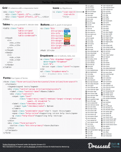


© Copyright 2026