
YVWA Style A - Water-Cooled Screw Chiller Installation, Operation
WATER-COOLED SCREW LIQUID CHILLERS INSTALLATION, OPERATION, AND MAINTENANCE Supersedes: 201.30-ICOM2 (113) Form 201.30-ICOM2 (415) 035 23322 000 MODEL YVWA Dual Compressor 50 Hz and 60 Hz 200 - 300 Tons 703 - 1055 kW LD16421 R-134a Issue Date: April 30, 2015 FORM 201.30-ICOM2 ISSUE DATE: 4/30/2015 IMPORTANT! READ BEFORE PROCEEDING! GENERAL SAFETY GUIDELINES This equipment is a relatively complicated apparatus. During rigging, installation, operation, maintenance, or service, individuals may be exposed to certain components or conditions including, but not limited to: heavy objects, refrigerants, materials under pressure, rotating components, and both high and low voltage. Each of these items has the potential, if misused or handled improperly, to cause bodily injury or death. It is the obligation and responsibility of rigging, installation, and operating/service personnel to identify and recognize these inherent hazards, protect themselves, and proceed safely in completing their tasks. Failure to comply with any of these requirements could result in serious damage to the equipment and the property in which it is situated, as well as severe personal injury or death to themselves and people at the site. This document is intended for use by owner-authorized rigging, installation, and operating/service personnel. It is expected that these individuals possess independent training that will enable them to perform their assigned tasks properly and safely. It is essential that, prior to performing any task on this equipment, this individual shall have read and understood the on-product labels, this document and any referenced materials. This individual shall also be familiar with and comply with all applicable industry and governmental standards and regulations pertaining to the task in question. SAFETY SYMBOLS The following symbols are used in this document to alert the reader to specific situations: Indicates a possible hazardous situation which will result in death or serious injury if proper care is not taken. Identifies a hazard which could lead to damage to the machine, damage to other equipment and/or environmental pollution if proper care is not taken or instructions and are not followed. Indicates a potentially hazardous situation which will result in possible injuries or damage to equipment if proper care is not taken. Highlights additional information useful to the technician in completing the work being performed properly. External wiring, unless specified as an optional connection in the manufacturer’s product line, is not to be connected inside the control cabinet. Devices such as relays, switches, transducers and controls and any external wiring must not be installed inside the micro panel. All wiring must be in accordance with Johnson Controls’ published specifications and must be performed only by a qualified electrician. Johnson Controls will NOT be responsible for damage/problems resulting from improper connections to the controls or application of improper control signals. Failure to follow this warning will void the manufacturer’s warranty and cause serious damage to property or personal injury. 2 JOHNSON CONTROLS FORM 201.30-ICOM2 ISSUE DATE: 4/30/2015 CHANGEABILITY OF THIS DOCUMENT In complying with Johnson Controls’ policy for continuous product improvement, the information contained in this document is subject to change without notice. Johnson Controls makes no commitment to update or provide current information automatically to the manual or product owner. Updated manuals, if applicable, can be obtained by contacting the nearest Johnson Controls Service office or accessing the Johnson Controls QuickLIT website at http://cgproducts. johnsoncontrols.com. It is the responsibility of rigging, lifting, and operating/ service personnel to verify the applicability of these documents to the equipment. If there is any question regarding the applicability of these documents, rigging, lifting, and operating/service personnel should verify whether the equipment has been modified and if current literature is available from the owner of the equipment prior to performing any work on the chiller. CHANGE BARS Revisions made to this document are indicated with a line along the left or right hand column in the area the revision was made. These revisions are to technical information and any other changes in spelling, grammar or formatting are not included. ASSOCIATED LITERATURE MANUAL DESCRIPTION FORM NUMBER Field Connections and Control Wiring for YVWA Chiller 201.30-PW2 YVWA Renewal Parts 201.30-RP1 YVWA Chiller Installation Checklist 201.30-CL1 YVWA Chiller Start-up Checklist and Request for Authorized Start-up Technician 201.30-CL2 Limited Warranty 50.05-NM2 Shipping Damage Claims 50.15-NM Long-Term Storage Periodic Checklist and Logs for YR, YS, and YVWA Screw Chillers 50.20-CL9 JOHNSON CONTROLS 3 FORM 201.30-ICOM2 ISSUE DATE: 4/30/2015 NOMENCLATURE YVWA MX* EE MX* B A X MODEL NOMINAL CAP TR = 200-300 kW = 7031055 STARTER A=Frame A B=Frame B C = Frame C D = Frame D COND EVAP TUBES* TUBES* M N M N A S 0200 X=NO SELECTION Q=SPECIAL QUOTE APPLICATION S=Std Water Chiller T=Ice Thermal Storage A=Heat Pump PASS B=Evap: 2-pass; Cond: 1 pass C=Evap: 3-pass; Cond: 1 pass E=Evap: 2-pass; Cond: 2 pass F=Evap: 3-pass; Cond: 2 pass H=Evap: 2-pass; Cond: 3 pass I =Evap: 3-pass; Cond: 3 pass 2 CMPR EE=136/136 mm FE=145/136 mm FF=145/145 mm UNIT TYPE YORK Variable Speed Screw Water-Cooled Chiller Design Series *First letter represents shell size. The second letter designates the number and diameter of of tubes. VARIABLE SPEED DRIVE NOMENCLATURE TVP 2CMPR X W - 46) A VSD PANEL NUMBER OF COMPRESSORS 4 COOLING W = Water G = Glycol FRAME SIZE A B C D VOLTAGE 40 = 380V 60Hz 50 = 400V 50Hz 46 = 460V 60Hz POWER INTERRUPTION 65 = 380V 50Hz 68 = 415V 50Hz X = Base Model B = Circuit Breaker D = Disconnect Switch JOHNSON CONTROLS FORM 201.30-ICOM2 ISSUE DATE: 4/30/2015 TABLE OF CONTENTS SECTION 1 - GENERAL CHILLER INFORMATION AND SAFETY....................................................................... 15 Introduction...................................................................................................................................................... 15 About this Manual............................................................................................................................................ 15 Warranty.......................................................................................................................................................... 15 Quality Assurance........................................................................................................................................... 15 Fluorinated Greenhouse Gases...................................................................................................................... 16 Responsibility for Safety.................................................................................................................................. 16 Misuse of Equipment....................................................................................................................................... 16 Suitability For Application.......................................................................................................................16 Brine Applications...................................................................................................................................16 Structural Support..................................................................................................................................16 Mechanical Strength ..............................................................................................................................16 General Access......................................................................................................................................16 Pressure Systems..................................................................................................................................17 Electrical.................................................................................................................................................17 Refrigerants and Oils..............................................................................................................................17 High Temperature and Pressure Cleaning............................................................................................. 17 Emergency Shutdown (Optional)........................................................................................................... 17 Safety Labels..........................................................................................................................................17 SECTION 2 - PRODUCT DESCRIPTION................................................................................................................19 Evaporator....................................................................................................................................................... 23 Condenser....................................................................................................................................................... 23 Refrigerant Circuit........................................................................................................................................... 23 Building Automation System (BAS) Capabilities............................................................................................. 23 Microcomputer Control Center........................................................................................................................ 24 Options............................................................................................................................................................ 24 Evaporator Options................................................................................................................................24 Controls Options.....................................................................................................................................25 General Options.....................................................................................................................................25 Relief Valves ..................................................................................................................................25 Electrical Isolation...........................................................................................................................25 Vibration Isolation...................................................................................................................................25 SECTION 3 - HANDLING, STORAGE, INSTALLATION AND REASSEMBLY...................................................... 27 Shipment and Storage..................................................................................................................................... 27 Chiller Unit (Form 1)...............................................................................................................................28 Miscellaneous Items.......................................................................................................................28 Chiller Unit (Form 2)...............................................................................................................................28 Miscellaneous Items.......................................................................................................................28 Chiller Unit (Form 7)...............................................................................................................................28 Two Drivelines.................................................................................................................................28 Shells..............................................................................................................................................28 Variable Speed Drive......................................................................................................................29 Discharge Isolation Valves..............................................................................................................29 Miscellaneous Items.......................................................................................................................29 Inspection, Damage, and Shortage................................................................................................................. 29 Lifting Weights................................................................................................................................................. 29 Moving the Chiller for Forms 1 and 2.............................................................................................................. 31 Location .......................................................................................................................................................... 32 JOHNSON CONTROLS 5 FORM 201.30-ICOM2 ISSUE DATE: 4/30/2015 TABLE OF CONTENTS (CONT'D) Foundation...................................................................................................................................................... 32 Clearance for Service ..................................................................................................................................... 32 Installing Elastomeric Vibration Isolator Pads................................................................................................. 33 Checking Unit Alignment........................................................................................................................33 Checking the Isolator Pad Deflection..................................................................................................... 33 Installing Optional Spring Isolators.................................................................................................................. 34 Form 7 Reassembly........................................................................................................................................ 35 Additional Instructions for Form 7 Reassembly...................................................................................... 35 Installing the Pads or Spring Isolators.................................................................................................... 38 Installing the Heat Exchanger Piping .................................................................................................... 39 Installing the Liquid Injection Piping....................................................................................................... 39 Installing Oil Return Piping..................................................................................................................... 40 Installing Driveline Assemblies............................................................................................................... 40 Installing Oil Separators.........................................................................................................................42 Installing Discharge Muffler Lines.......................................................................................................... 43 Installing Oil Separator Discharge Piping............................................................................................... 43 Installing Compressor Piping.................................................................................................................. 45 Installing Oil Supply Piping..................................................................................................................... 45 Installing Economizer Piping to Compressor.......................................................................................... 46 Installing Variable Speed Drive (VSD).................................................................................................... 46 Connecting VSD Cooling Hoses............................................................................................................ 47 Piping Joint Assembly..................................................................................................................................... 48 Assembly of Fasteners and Piping......................................................................................................... 48 Pipe Thread Joints.......................................................................................................................................... 49 Procedures.............................................................................................................................................49 Cleaning..........................................................................................................................................49 Priming............................................................................................................................................49 Gasket Joints................................................................................................................................................... 49 Assembling Gasket Joints...................................................................................................................... 49 Torque Values.................................................................................................................................................. 50 O-Ring Joints................................................................................................................................................... 51 Assembly of O-ring Joints...................................................................................................................... 51 Adjustable End Assembly...............................................................................................................51 Straight Non-Adjustable End Assembly..........................................................................................52 Assembly of O-ring Face Seal Fittings .................................................................................................. 52 O-ring Face Seal Assembly............................................................................................................52 Brazed Joints .................................................................................................................................................. 53 Assembling Brazed Joints...................................................................................................................... 53 Piping Connections......................................................................................................................................... 54 Check for Piping Alignment............................................................................................................................. 54 Condenser and Chilled Liquid Piping ............................................................................................................. 54 General Requirements.................................................................................................................................... 54 Piping Connections................................................................................................................................55 Condenser Water Circuit........................................................................................................................55 Checking Piping Circuits and Venting Air............................................................................................... 55 Water Treatment.............................................................................................................................................. 56 Pipework Arrangement.................................................................................................................................... 56 Minimum Water Volume.................................................................................................................................. 56 Leaving Water Temperature Out Of Range..................................................................................................... 57 6 JOHNSON CONTROLS FORM 201.30-ICOM2 ISSUE DATE: 4/30/2015 TABLE OF CONTENTS (CONT'D) Variable Primary Flow .................................................................................................................................... 57 Nozzle Connections........................................................................................................................................ 57 Options for Flanges......................................................................................................................................... 57 Refrigerant Relief Piping ................................................................................................................................ 57 Unit Piping....................................................................................................................................................... 59 Electrical Connection....................................................................................................................................... 59 Power Wiring................................................................................................................................................... 59 Power Supply Wiring....................................................................................................................................... 59 115VAC Control Supply Transformer............................................................................................................... 59 Control Wiring.................................................................................................................................................. 59 Chilled Liquid and Condenser Pump Starter.......................................................................................... 59 Run Contact...........................................................................................................................................60 Alarm Contacts.......................................................................................................................................60 System Inputs.................................................................................................................................................. 60 Chilled Liquid Flow Switch...................................................................................................................... 60 Condenser Liquid Flow Switch............................................................................................................... 60 Remote Run Permissive......................................................................................................................... 60 Remote Print..........................................................................................................................................60 Optional Heat Pump Remote Mode Selection........................................................................................ 60 Optional Remote Setpoint Offset............................................................................................................ 60 Analog Inputs.................................................................................................................................................. 60 Leaving Chilled Liquid Temperature Reset Control................................................................................ 60 How to Receive Voltage or Current Signal......................................................................................60 0-10 or 2-10 VDC Reset Input........................................................................................................61 0–20 or 4-20 mA Reset Input..........................................................................................................61 Leaving Condenser Liquid Temperature Reset Control......................................................................... 61 Current Limit Reset Control.................................................................................................................... 61 How to Receive Voltage or Current Signal......................................................................................61 0-10 or 2-10 VDC Reset Input........................................................................................................61 0–20 or 4-20 mA Reset Input..........................................................................................................61 SECTION 4 - TECHNICAL DATA............................................................................................................................67 Compressor Unit Dimensions.......................................................................................................................... 74 Dimensions of Evaporator Nozzle Arrangements............................................................................................ 75 Dimensions of Condenser Nozzle Arrangements............................................................................................76 SECTION 5 - COMMISSIONING.............................................................................................................................79 Preparation...................................................................................................................................................... 79 Refrigerant Charge.................................................................................................................................79 Service and Oil Line Valves.................................................................................................................... 79 Compressor Oil......................................................................................................................................79 First Time Start-up........................................................................................................................................... 79 Loading...................................................................................................................................................79 JOHNSON CONTROLS 7 FORM 201.30-ICOM2 ISSUE DATE: 4/30/2015 TABLE OF CONTENTS (CONT'D) SECTION 6 - OPERATION......................................................................................................................................85 Operating Controls ......................................................................................................................................... 85 Unit Switch.............................................................................................................................................85 Keypad...................................................................................................................................................85 Keypad Data Entry Mode.......................................................................................................................86 Enter Data Entry Mode...................................................................................................................86 Display....................................................................................................................................................86 Basic Operating Sequence.............................................................................................................................. 86 Start Sequence and Loading.................................................................................................................. 86 Anti-Recycle Timer.................................................................................................................................86 Evaporator and Condenser Pump Control............................................................................................. 86 Alarms....................................................................................................................................................87 Chiller Run Contact................................................................................................................................87 Pulldown Current Limit Setpoint............................................................................................................. 88 Leaving Chilled Liquid Temperature (LCHLT) Reset Control ................................................................ 88 Optional Heat Pump Mode Selection..................................................................................................... 89 Optional Heat Pump Leaving Condenser Liquid Temperature (LCLT) Reset Control............................ 89 Current Limit Reset Control.................................................................................................................... 89 User Interface.................................................................................................................................................. 90 General Unit and System Status Messages........................................................................................... 91 Load or Unloading Limit Messages........................................................................................................ 92 Fault Messages............................................................................................................................................... 93 Unit Warnings.........................................................................................................................................93 Low Battery............................................................................................................................................93 Unit Safeties (Faults)..............................................................................................................................94 VSD Fault Data......................................................................................................................................94 First Fault Code..............................................................................................................................94 All Fault Bits....................................................................................................................................94 Fault Data.......................................................................................................................................94 System Safeties (Faults)........................................................................................................................97 Multiple Systems ...................................................................................................................................97 System 1 Data Key Operation.............................................................................................................. 103 Pressure Messages......................................................................................................................103 Temperature Messages................................................................................................................103 Miscellaneous Messages..............................................................................................................103 System 2 Data Key Operation.............................................................................................................. 104 Sensor Displays...................................................................................................................................104 Operating Hours/Start Counter Key..................................................................................................... 105 Non-Heat Pump Applications........................................................................................................108 Heat Pump Applications................................................................................................................108 Service Mode Access:.......................................................................................................................... 110 Default Values...................................................................................................................................... 111 System Lead/Lag Control Mode Selection.................................................................................... 112 Remote Temperature Reset Input................................................................................................. 112 Remote Current Limit Input........................................................................................................... 113 Schedule Key Operation...................................................................................................................... 114 Acceptable Printers....................................................................................................................................... 117 Okidata OKIPOS 441 Printer................................................................................................................ 117 8 JOHNSON CONTROLS FORM 201.30-ICOM2 ISSUE DATE: 4/30/2015 TABLE OF CONTENTS (CONT'D) Printer Connections....................................................................................................................................... 117 Required Hardware:............................................................................................................................. 117 Cable............................................................................................................................................. 117 Connectors.................................................................................................................................... 117 Printer Setup................................................................................................................................................. 117 Okidata OKIPOS 441 Printer................................................................................................................ 118 Printing A Report........................................................................................................................................... 118 History Data Printout............................................................................................................................120 BAS Communications................................................................................................................................... 122 YORK Talk 2 Communications............................................................................................................. 122 Received Data (Control Data).......................................................................................................122 Transmitted Data..........................................................................................................................122 SECTION 7 - MAINTENANCE...............................................................................................................................125 General Requirements.................................................................................................................................. 125 Daily Operating Inspections.......................................................................................................................... 126 Routine Inspections..............................................................................................................................126 Compressor Oil............................................................................................................................................. 126 Check Operational Oil Level................................................................................................................. 126 Oil Level...............................................................................................................................................126 Start-Up................................................................................................................................................126 Operation..............................................................................................................................................127 Oil Analysis...........................................................................................................................................127 Removing the Compressor Oil............................................................................................................. 127 Adding Compressor Oil........................................................................................................................128 Oil Filter................................................................................................................................................128 Oil Filter Replacement................................................................................................................................... 129 Replacing the Filter Drier......................................................................................................................130 Determining Correct Refrigerant Charge Level.................................................................................... 131 Equations:.....................................................................................................................................131 Definitions Of Temperatures:........................................................................................................131 Refrigerant Charging..................................................................................................................................... 131 Handling Refrigerant For Dismantling and Repairs....................................................................................... 131 Checking the Motor Windings.............................................................................................................. 131 Checking System For Leaks......................................................................................................................... 132 Leak Testing During Operation............................................................................................................. 132 Refrigerant Leak Checking............................................................................................................................ 132 Pressure Connections................................................................................................................................... 132 Conduct R-134a Pressure Test.....................................................................................................132 Testing For Evaporator and Condenser Tube Leaks..................................................................................... 133 Evacuation and Dehydration of Unit.............................................................................................................. 134 Vacuum Dehydration............................................................................................................................134 Improve Dehydration.....................................................................................................................135 Remaining System Moisture.........................................................................................................135 Vacuum Testing.............................................................................................................................135 Condensers and evaporators Maintenance.................................................................................................. 136 General.................................................................................................................................................136 Chemical Water Treatment................................................................................................................... 136 JOHNSON CONTROLS 9 FORM 201.30-ICOM2 ISSUE DATE: 4/30/2015 TABLE OF CONTENTS (CONT'D) Cleaning Evaporator And Condenser Tubes................................................................................................. 136 Condenser Tubes.................................................................................................................................136 Tube Fouling........................................................................................................................................136 Non-condensable Gas ......................................................................................................................... 137 Evaporator Tubes.................................................................................................................................137 Waterside Tube Cleaning Procedure ...........................................................................................137 Chemical Cleaning Procedure......................................................................................................137 Mechanical Tube Cleaning Procedure..........................................................................................137 Compressor Maintenance............................................................................................................................. 138 Electrical Controls......................................................................................................................................... 138 Checking VSD Coolant Level............................................................................................................... 138 Preventive Maintenance....................................................................................................................... 138 SECTION 8 - TROUBLESHOOTING.....................................................................................................................139 Abnormal Operation, Analysis and Correction.............................................................................................. 139 Troubleshooting the Compressor and Oil Separation System...................................................................... 139 SECTION 9 - DECOMMISSIONING, DISMANTLING, AND DISPOSAL.............................................................. 142 Temperature.................................................................................................................................................. 143 10 JOHNSON CONTROLS FORM 201.30-ICOM2 ISSUE DATE: 4/30/2015 LIST OF FIGURES FIGURE 1 - Emergency Shutdown Handle�������������������������������������������������������������������������������������������������������������17 FIGURE 2 - YVWA Chiller Major Components (Front View)�����������������������������������������������������������������������������������20 FIGURE 3 - YVWA Chiller Major Components (Rear View)������������������������������������������������������������������������������������21 FIGURE 4 - Basic System Control And VSD System Architecture��������������������������������������������������������������������������22 FIGURE 5 - Control Center User Interface��������������������������������������������������������������������������������������������������������������24 FIGURE 6 - Unit Rigging for Forms 1 and 2������������������������������������������������������������������������������������������������������������31 FIGURE 7 - Service Clearance Requirements��������������������������������������������������������������������������������������������������������32 FIGURE 8 - Elastomeric Vibration Isolator Pad Mounts (Standard) - Inches (mm)������������������������������������������������� 33 FIGURE 9 - Spring Isolators (Optional) - Inches (mm)��������������������������������������������������������������������������������������������34 FIGURE 10 - Rigging the Evaporator����������������������������������������������������������������������������������������������������������������������36 FIGURE 11 - Condenser Rigging����������������������������������������������������������������������������������������������������������������������������37 FIGURE 12 - Isolator Installation�����������������������������������������������������������������������������������������������������������������������������38 FIGURE 13 - Heat Exchanger Shipping Brackets���������������������������������������������������������������������������������������������������39 FIGURE 14 - Heat Exchanger Pipes�����������������������������������������������������������������������������������������������������������������������39 FIGURE 15 - Liquid Injection Piping������������������������������������������������������������������������������������������������������������������������40 FIGURE 16 - Filter Drier and Piping �����������������������������������������������������������������������������������������������������������������������40 FIGURE 17 - Driveline (Compressor/Motor) Assemblies����������������������������������������������������������������������������������������41 FIGURE 18 - Oil Separators������������������������������������������������������������������������������������������������������������������������������������42 FIGURE 19 - Mufflers Installation����������������������������������������������������������������������������������������������������������������������������43 FIGURE 20 - Oil Separator Discharge Piping���������������������������������������������������������������������������������������������������������44 FIGURE 21 - Transducer, Eductor and Oil Return Piping ��������������������������������������������������������������������������������������45 FIGURE 22 - Oil Supply Piping�������������������������������������������������������������������������������������������������������������������������������45 FIGURE 23 - Piping to Compressor������������������������������������������������������������������������������������������������������������������������46 FIGURE 24 - Variable Speed Drive (VSD)��������������������������������������������������������������������������������������������������������������47 FIGURE 25 - VSD Cooling Hoses ��������������������������������������������������������������������������������������������������������������������������48 FIGURE 26 - Torque Pattern�����������������������������������������������������������������������������������������������������������������������������������49 FIGURE 27 - Adjustable End Fitting������������������������������������������������������������������������������������������������������������������������51 FIGURE 28 - Back Off Locknut�������������������������������������������������������������������������������������������������������������������������������51 FIGURE 29 - Screw Fitting Into Port�����������������������������������������������������������������������������������������������������������������������51 FIGURE 30 - Torque Fitting�������������������������������������������������������������������������������������������������������������������������������������51 FIGURE 31 - Sae Straight Thread O-Ring Port�������������������������������������������������������������������������������������������������������52 FIGURE 32 - Brazed Joints�������������������������������������������������������������������������������������������������������������������������������������53 FIGURE 33 - Schematic of a Typical Piping Arrangement��������������������������������������������������������������������������������������56 FIGURE 34 - Leaving Water Temperature Out-of-Range Suggested Layout ��������������������������������������������������������� 57 FIGURE 35 - Victaulic Groove���������������������������������������������������������������������������������������������������������������������������������57 FIGURE 36 - Flange Attachment�����������������������������������������������������������������������������������������������������������������������������57 FIGURE 37 - Typical Components of Relief Piping�������������������������������������������������������������������������������������������������58 FIGURE 38 - Power Connections���������������������������������������������������������������������������������������������������������������������������64 FIGURE 39 - Compressor Unit Dimensions������������������������������������������������������������������������������������������������������������75 FIGURE 40 - Evaporators - Compact Water Boxes (2-Pass)����������������������������������������������������������������������������������76 FIGURE 41 - Evaporators - Compact Water Boxes (3-Pass)����������������������������������������������������������������������������������76 FIGURE 42 - Condensers - Compact Water Boxes (1-Pass)����������������������������������������������������������������������������������77 FIGURE 43 - Condensers - Compact Water Boxes (2-Pass)����������������������������������������������������������������������������������77 FIGURE 44 - Condensers - Compact Water Boxes (3-Pass)����������������������������������������������������������������������������������77 FIGURE 45 - Keypad and Display���������������������������������������������������������������������������������������������������������������������������85 FIGURE 46 - Control Operation������������������������������������������������������������������������������������������������������������������������������87 FIGURE 47 - Status Key�����������������������������������������������������������������������������������������������������������������������������������������91 FIGURE 48 - Unit Data Key����������������������������������������������������������������������������������������������������������������������������������102 FIGURE 49 - System Data Keys (1-2)������������������������������������������������������������������������������������������������������������������103 FIGURE 50 - VSD Data and Operating Hours/Start Counter Keys�����������������������������������������������������������������������105 FIGURE 51 - History Key��������������������������������������������������������������������������������������������������������������������������������������106 FIGURE 52 - Setpoints Key����������������������������������������������������������������������������������������������������������������������������������108 FIGURE 53 - Setpoint High and Low Limits Defined By Control Range (CR)������������������������������������������������������� 109 FIGURE 54 - Program Key������������������������������������������������������������������������������������������������������������������������������������ 110 FIGURE 55 - Options Key������������������������������������������������������������������������������������������������������������������������������������� 112 JOHNSON CONTROLS 11 FORM 201.30-ICOM2 ISSUE DATE: 4/30/2015 LIST OF FIGURES (CONT'D) FIGURE 56 - Date/Time and Schedule Key���������������������������������������������������������������������������������������������������������� 114 FIGURE 57 - Manual Override and Print Key������������������������������������������������������������������������������������������������������� 116 FIGURE 58 - Printer Cable Connection From YVWA Chiller to a Computer �������������������������������������������������������� 116 FIGURE 59 - Printer Cable Connection From YVWA Chiller to a Serial Printer���������������������������������������������������� 117 FIGURE 60 - Sample Printout������������������������������������������������������������������������������������������������������������������������������� 119 FIGURE 61 - System Switches and Service Keys������������������������������������������������������������������������������������������������121 FIGURE 62 - E-Link Gateway Option��������������������������������������������������������������������������������������������������������������������122 FIGURE 63 - Charging Oil ������������������������������������������������������������������������������������������������������������������������������������128 FIGURE 64 - Oil Filter Assembly���������������������������������������������������������������������������������������������������������������������������129 FIGURE 65 - Oil Eductor Assembly����������������������������������������������������������������������������������������������������������������������130 FIGURE 66 - Motor Windings Diagram�����������������������������������������������������������������������������������������������������������������132 FIGURE 67 - Saturation Curve������������������������������������������������������������������������������������������������������������������������������135 12 JOHNSON CONTROLS FORM 201.30-ICOM2 ISSUE DATE: 4/30/2015 LIST OF TABLES TABLE 1 - Unit Weight��������������������������������������������������������������������������������������������������������������������������������������������30 TABLE 2 - Service Clearance Requirments������������������������������������������������������������������������������������������������������������32 TABLE 3 - Evaporator Dimensions (In/Mm)������������������������������������������������������������������������������������������������������������36 TABLE 4 - Condenser Dimensions (In/Mm)������������������������������������������������������������������������������������������������������������37 TABLE 5 - Compressor Weight and Dimensions����������������������������������������������������������������������������������������������������41 TABLE 6 - Oil Separator Weight and Dimensions��������������������������������������������������������������������������������������������������42 TABLE 7 - VSD Weight and Dimensions����������������������������������������������������������������������������������������������������������������47 TABLE 8 - Assembly Compounds���������������������������������������������������������������������������������������������������������������������������48 TABLE 9 - ANSI 150 LB Flange Torque Specifications�������������������������������������������������������������������������������������������50 TABLE 10 - ANSI 300 LB Flange Torque Specifications�����������������������������������������������������������������������������������������50 TABLE 11 - SAE J429 Gr 5 Bolts Torque Specifications�����������������������������������������������������������������������������������������50 TABLE 12 - O-Ring Assembly Torque Specifications����������������������������������������������������������������������������������������������52 TABLE 13 - Brazed Joints���������������������������������������������������������������������������������������������������������������������������������������53 TABLE 14 - Water Volume for Applications�������������������������������������������������������������������������������������������������������������56 TABLE 15 - Evaporator and Condenser Water Capacity (lb/kg) and Volume GAL (l) �������������������������������������������� 56 TABLE 16 - Refrigerant Relief Characteristics (Per Valve)�������������������������������������������������������������������������������������58 TABLE 17 - System Input Connections�������������������������������������������������������������������������������������������������������������������60 TABLE 18 - Lug Data (UL/ASME/CE) - Pin 22/Power Field�����������������������������������������������������������������������������������65 TABLE 19 - Voltage Variations �������������������������������������������������������������������������������������������������������������������������������66 TABLE 20 - Complete Pin Number Description �����������������������������������������������������������������������������������������������������67 TABLE 21 - Evaporator nozzle dimensions - in (mm)���������������������������������������������������������������������������������������������75 TABLE 22 - Condenser Nozzle Dimensions - in (mm)��������������������������������������������������������������������������������������������76 TABLE 23 - Water Flow Rate Limits (GPM / l/s) (Based on Standard Tubes at Design Full Load Conditions)������ 77 TABLE 24 - Load Limiting Values���������������������������������������������������������������������������������������������������������������������������88 TABLE 25 - Unit Warnings��������������������������������������������������������������������������������������������������������������������������������������93 TABLE 26 - Unit Safeties (Faults)���������������������������������������������������������������������������������������������������������������������������95 TABLE 27 - System Safeties (Faults)���������������������������������������������������������������������������������������������������������������������97 TABLE 28 - HPCO Mechanical Cutouts������������������������������������������������������������������������������������������������������������������99 TABLE 29 - Timer Settings��������������������������������������������������������������������������������������������������������������������������������������99 TABLE 30 - Sensor Minimum/Maximum Outputs�������������������������������������������������������������������������������������������������104 TABLE 31 - Setpoint Values����������������������������������������������������������������������������������������������������������������������������������109 TABLE 32 - Programmable Operating Parameters����������������������������������������������������������������������������������������������� 111 TABLE 33 - OKIDATA OKIPOS 441���������������������������������������������������������������������������������������������������������������������� 117 TABLE 34 - Printout Types������������������������������������������������������������������������������������������������������������������������������������ 118 TABLE 35 - Real Time Number Errors������������������������������������������������������������������������������������������������������������������123 TABLE 36 - Operation/Inspection/Maintenance Requirements for YVWA Chillers����������������������������������������������� 125 TABLE 37 - Compressor Oil Limits�����������������������������������������������������������������������������������������������������������������������127 TABLE 38 - System Pressures�����������������������������������������������������������������������������������������������������������������������������134 TABLE 39 - Troubleshooting Guide����������������������������������������������������������������������������������������������������������������������139 TABLE 40 - Metric Conversion������������������������������������������������������������������������������������������������������������������������������143 JOHNSON CONTROLS 13 FORM 201.30-ICOM2 ISSUE DATE: 4/30/2015 THIS PAGE INTENTIONALLY LEFT BLANK. 14 JOHNSON CONTROLS FORM 201.30-ICOM2 ISSUE DATE: 4/30/2015 SECTION 1 - GENERAL CHILLER INFORMATION AND SAFETY INTRODUCTION YORK YVWA chillers are manufactured to the highest design and construction standards to ensure high performance, reliability and adaptability to all types of air conditioning installations. The unit is intended for cooling water or glycol solutions, and is not suitable for purposes other than those specified in this manual. ABOUT THIS MANUAL This manual and any other document supplied with the unit are the property of Johnson Controls which reserves all rights. This manual may not be reproduced, in whole or in part, without prior written authorization from an authorized Johnson Controls representative. In addition, this manual: • Includes suggested best working practices and procedures, which are issued for guidance only, and they do not take precedence over the above stated individual responsibility and/or local safety regulations. • Contains all the information required for correct installation and commissioning of the unit, together with operating and maintenance instructions. • Should be read thoroughly before attempting to operate or service the unit. • Contains detailed procedures, including installation, commissioning and maintenance tasks that must only be performed by suitably trained and qualified personnel. The manufacturer will not be liable for any injury or damage caused by incorrect installation, commissioning, operation or maintenance resulting from a failure to follow the procedures and instructions detailed in the manual. WARRANTY Johnson Controls warrants YVWA chillers in accordance with the Limited Warranty Engineered Systems Equipment procedure. Refer to Limited Warranty (Form 50.05-NM2). Johnson Controls warrants all equipment and materials against defects in workmanship and materials for a period of 18 months from the date of shipment or 12 months from the date of start-up, whichever comes first, unless labor or extended warranty has been purchased as part of the contract. The warranty is limited to parts only replacement and shipping of any faulty part, or subassembly, which has failed due to defects in workmanship and materials. All claims must be supported by evidence that the failure has occurred within the warranty period, and that the unit was operated within the designed parameters specified. All warranty claims must specify the unit model, serial number, order number, and run hours/starts. Model and serial number information is printed on the unit identification plate. The unit warranty will be void if any modification to the unit is carried out without prior written approval from Johnson Controls. For warranty purposes, the following conditions must be satisfied: • The initial start of the unit must be carried out by trained personnel from an authorized Johnson Controls Field Service Office. • Only genuine YORK approved spare parts, oils, coolants, and refrigerants must be used. • All of the scheduled maintenance operations detailed in this manual must be performed at the specified times by suitably trained and qualified personnel. • Failure to satisfy any of these conditions will automatically void the warranty. Refer to Limited Warranty (Form 50.05-NM2) for complete details. QUALITY ASSURANCE Units conform with the following European Directives: • Equipment Directive (2006/42/EC) • EMC Directive (2004/108/EC) • Pressure Equipment Directive (97/23/EC) • Low Voltage Directive (2006/95/EC) • Safety Code for (EN378-2 (2008)) JOHNSON CONTROLS 1 Mechanical Refrigeration 15 FORM 201.30-ICOM2 ISSUE DATE: 4/30/2015 SECTION 1 - GENERAL CHILLER INFORMATION AND SAFETY • AHRI 550/590 and 551/591 - Water Chilling Packages using the Vapor Compression Cycle. • Personal safety, the safety of other personnel, and the equipment. • GB/T 18430.1 - Water Chilling (Heat Pump) Packages Using The Vapor Compression Cycle - Part 1: Water Chilling (Heat Pump) Packages For Industrial & Commercial And Similar Applications. • Correct utilization of the equipment in accordance with the procedures detailed in the manual. • GB25131 - Safety Requirements For Water Chillers (Heat Pump) Using The Vapor Compression Cycle. • GB150/151 - Steel Pressure Vessels/Tubular Heat Exchangers. • ANSI/ASHRAE 34 - Number Designation And Safety Classification Of Refrigerants. • ASHRAE 90.1 - Energy Standard For Buildings Except Low-Rise Residential Buildings. • Machinery Directive (2006/42/EC) • EMC Directive (2004/108/EC) • Pressure Equipment Directive (97/23/EC) • Safety Code for Mechanical Refrigeration (EN 378-2) • S afety of machinery - Electrical Equipment of Machine (EN 60204-1) • M anufactured in an EN ISO 9001 accredited organization • ISO 9614 – Determination of sound power levels of noise sources using sound intensity • C onform to CE Testing Services for construction of chillers and provide CE Listed Mark FLUORINATED GREENHOUSE GASES • This equipment contains fluorinated greenhouse gases covered by the Kyoto Protocol. • The global warming potential of the refrigerant (R-134a) used in this unit is 1300. The refrigerant quantity is stated in this document. • The fluorinated greenhouse gases in this equipment may not be vented to the atmosphere. RESPONSIBILITY FOR SAFETY Every care has been taken in the design and manufacture of the unit to ensure compliance with the safety requirements. However, the individual operating or working on any equipment is primarily responsible for: 16 MISUSE OF EQUIPMENT Suitability For Application The unit is intended for cooling water or glycol solutions and is not suitable for purposes other than those specified in these instructions. Any use of the equipment other than its intended use, or operation of the equipment contrary to the relevant procedures may result in injury to the operator, or damage to the equipment. The unit must not be operated outside the design parameters specified in this manual. Brine Applications When the chiller is not running, cold brine should NOT be run through the evaporator. However, if there is brine running through the evaporator, there must be flow through the condenser to prevent tubes from freezing. Structural Support Structural support of the unit must be provided as indicated in these instructions. Failure to provide proper support may result in injury to the operator, or damage to the equipment and/or building. Mechanical Strength The unit is not designed to withstand loads or stresses from adjacent equipment, pipework, or structures. Additional components must not be mounted on the unit. Any such extraneous loads may cause structural failure and may result in injury to the operator, or damage to the equipment. General Access There are a number of areas and features, which may be a hazard and potentially cause injury when working on the unit unless suitable safety precautions are taken. Make sure access to the unit is restricted to suitably qualified personnel, who are familiar with the potential hazards and precautions necessary for safe operation and maintenance of equipment containing high temperatures, pressures, and voltages. JOHNSON CONTROLS FORM 201.30-ICOM2 ISSUE DATE: 4/30/2015 SECTION 1 - GENERAL CHILLER INFORMATION AND SAFETY Pressure Systems 1 The unit contains refrigerant vapor and liquid under pressure, release of which can be a danger and cause injury. The user should make sure that care is taken during installation, operation, and maintenance to avoid damage to the pressure system. No attempt should be made to gain access to the component parts of the pressure system other than by suitably trained and qualified personnel. Electrical The unit must be grounded. No installation or maintenance work should be attempted on the electrical equipment without first switching the power off, isolating and locking-off the power supply. Servicing and maintenance on live equipment must not be attempted. No attempt should be made to gain access to the control panel or electrical enclosures during normal operation of the unit. Components may also have sharp edges. Reasonable care should be taken when working in contact with any components to avoid risk of minor abrasions and lacerations. Figure 1 - EMERGENCY SHUTDOWN HANDLE Safety Labels For safe operation, read the instructions first. Refrigerants and Oils Refrigerants and oils used in the unit are generally nontoxic, non-flammable, and non-corrosive, and pose no special safety hazards. Use of gloves and safety glasses is recommended when working on the unit. The buildup of refrigerant vapor, from a leak for example, does pose a risk of asphyxiation in confined or enclosed spaces and attention should be given to good ventilation. Warning: This machine may start automatically without prior warning. High Temperature and Pressure Cleaning Warning: Safety relief valve may discharge gas or liquid without prior warning. High temperature and pressure cleaning methods (e.g., steam cleaning) should not be used on any part of the pressure system as this may cause operation of the pressure relief device(s). Detergents and solvents, which may cause corrosion, should also be avoided. Warning: Hot surface. Warning: Isolate all electrical sources of supply before opening or removing the cover, as lethal voltages may exist. Emergency Shutdown (Optional) In case of emergency, the unit can be stopped from the control panel if it is fitted with the optional circuit breaker (red and yellow as shown below) or non-fused disconnect switch. JOHNSON CONTROLS General attention symbol. Warning: On isolating the supply it may take up to 300 seconds for the capacitor voltage to fall below 50 volts. 17 FORM 201.30-ICOM2 ISSUE DATE: 4/30/2015 THIS PAGE INTENTIONALLY LEFT BLANK. 18 JOHNSON CONTROLS FORM 201.30-ICOM2 ISSUE DATE: 4/30/2015 SECTION 2 - PRODUCT DESCRIPTION YORK YVWA chillers are designed for water or glycol cooling. All units are designed to be located in an equipment room unless the unit was ordered specially for outside applications. The units are completely assembled with all interconnecting refrigerant piping and internal wiring, ready for field installation. Prior to delivery, the unit is: • Pressure tested, • Evacuated, and • Fully charged with refrigerant and oil in each independent refrigerant circuit. All exposed power wiring is routed through liquidtight, non-metallic conduit. The YVWA chiller combines the modern screw compressor design with the latest Variable Speed Drive (VSD) technology. The VSD enables the compressor speed to match the system load, and provides soft starts with no electrical inrush. The lack of heat buildup on start-up also reduces required off time between starts to two minutes. JOHNSON CONTROLS COMPONENTS The YVWA chiller, as shown in Figure 2 on page 20, and Figure 3 on page 21, consists of: • Two screw compressors with mufflers • A hybrid falling film evaporator • A water-cooled condenser • Two economizer heat exchangers • Two oil separators • VSD with control panel Oil separators utilize no moving parts, and are rated for 388 psig (2.68 MPa) design pressure. Oil cooling is accomplished by refrigerant leaving the eductor flashing in the suction line, which cools the oil, motor, and compressor. An integral liquid cooled, transistorized, pulse-width modulated (PWM) VSD is controlled by the microprocessor control panel to start/stop, select compressors to run, and select compressor speed. Power factor is 95% at part or full load. The chiller microprocessor communicates with the VSD logic board via a 3-wire RS-485 opto-coupled data link. The VSD logic board runs one or both compressors to the speed requested by the chiller microprocessor to meet the load as shown in Figure 4 on page 17. 19 2 FORM 201.30-ICOM2 ISSUE DATE: 4/30/2015 SECTION 2 - PRODUCT DESCRIPTION 1 2 3 4 3 8 9 5 7 7 6 LD16421 1. Control Panel 6. Condenser 2. Variable Speed Drive (VSD) 7. Condenser Sight Glass 3. Oil Separator 8. Evaporator 4. Economizer Heat Exchanger 9. Condenser Water Nozzle 5. Return Water Box Figure 2 - YVWA CHILLER MAJOR COMPONENTS (FRONT VIEW) 20 JOHNSON CONTROLS FORM 201.30-ICOM2 ISSUE DATE: 4/30/2015 SECTION 2 - PRODUCT DESCRIPTION 2 2 4 3 4 1 6 5 7 8 1. Terminal Box 5. Evaporator Sight Glass 2. VSD 6. Evaporator Water Nozzle 3. Coolant Piping 7. Liquid Level Sensor 4. Compressor 8. Liquid Line LD16423 Figure 3 - YVWA CHILLER MAJOR COMPONENTS (REAR VIEW) JOHNSON CONTROLS 21 FORM 201.30-ICOM2 ISSUE DATE: 4/30/2015 SECTION 2 - PRODUCT DESCRIPTION INPUTS Pressure Transducers Temperature Sensors Switches Liquid Flow High Pressure Start/Stop Level Customer Supplied Contacts OUTPUTS (Relay Output Board) Solenoids Alarm Pump Compressor Heater Run Status CONTROL PANEL (Chiller Control Board) Microprocessor User Interface Display and Keypad VSD VSD Logic Board SCR Trigger Board Power Components PWM (Speed Control) COMMUNICATIONS Building Automation Printer Modem DISPLAY MOTOR KEYPAD LD15028 3 Phase Power Line Compressor 1 Power Driver (IGBT) AC/DC Rectifier Compressor 2 Rectifier Controller SCR Trigger Board IGBT Gate Driver Rectifier Inverter VSD Logic Board PWM Signal Signal From Main Control Panel LD15158 Figure 4 - BASIC SYSTEM CONTROL AND VSD SYSTEM ARCHITECTURE 22 JOHNSON CONTROLS FORM 201.30-ICOM2 ISSUE DATE: 4/30/2015 SECTION 2 - PRODUCT DESCRIPTION COMPRESSORS REFRIGERANT CIRCUIT The two compressors are direct drive, semi-hermetic type, and have rotary twin screws as shown in SECTION 3 - HANDLING, STORAGE, INSTALLATION, AND REASSEMBLY, which include: An independent refrigerant circuit is provided for each compressor. The refrigerant circuits use steel pipe. In addition, each of the refrigerant circuits has: • Muffler • Temperature actuated, off-cycle heater • IP55 terminal board • Precision machined cast iron housing • Gas-cooled, high efficiency, accessible hermetic compressor motor • Full suction gas flow through mesh screen filter with inherent internal thermal overload protection and external current overload • An oil separator, with no moving parts, and designed for minimum oil carryover, mounted in the discharge line of the compressor. • An economizer heat exchanger is located in the refrigerant circuit to improve refrigeration effect in the evaporator for increased chiller efficiency. ELECTRICAL Incoming single point power is standard, utilizing: • Lockable circuit breaker, terminal block, or non-fused disconnect EVAPORATOR • 115VAC control transformer The evaporator is a shell and tube, hybrid falling film heat exchanger, which contains a balance of flooded and falling film technology to optimize efficiency, minimize refrigerant charge, and maintain reliable control. A distribution system provides uniform refrigerant flow for optimum performance. • VSD with control panel CONDENSER The condenser is a shell and tube type, equipped with: Standard design includes powder painted steel cabinet with hinged, latched, and gasket sealed outer doors, equipped with wind struts for safer servicing. All exposed wiring is routed through a liquid-tight, UV stabilized, non-metallic conduit. BUILDING AUTOMATION SYSTEM (BAS) CAPABILITIES • Discharge gas baffle used to deflect the refrigerant gas from the tubes, and distribute the refrigerant gas flow properly. The E-Link Gateway provides a versatile connection between chiller equipment and open/standard protocols. • Integral subcoolers, located at the bottom of the condenser shell, provide highly effective liquid refrigerant subcooling to provide the highest cycle efficiency. • Efficiently manages the communication protocols currently used by YORK equipment, exposing the data in a consistent, organized, and defined fashion. • Refrigerant relief valves set at 388 psig (26.8 MPa) for 3/4" tubes and 340 psig (2.34 MPa) for 1" tubes. • The E-Link communication board is available as a factory installed option. • Removable steel waterboxes that: • Have design working pressure of 150 psig (10.3 kPa). • The board must be field commissioned to ensure communication protocol. • See Communication Protocol Mapping document for communication points. • Are tested at 225 psig (15.5 kPa). • Contain welded steel water baffles. • Have welded stub‑out water nozzle connections with ANSI/AWWA C-606 grooves, and are capped for shipment. • Have plugged 3/4 in. (19 mm) drain and vent connections provided in each waterbox. JOHNSON CONTROLS 23 2 FORM 201.30-ICOM2 ISSUE DATE: 4/30/2015 SECTION 2 - PRODUCT DESCRIPTION MICROCOMPUTER CONTROL CENTER The microcomputer control center, located on the VSD panel door as shown in Figure 5 on page 24, provides automatic control of chiller operation including compressor start/stop and load/unload anti-recycle timers, condenser and chilled water (CHW) pumps, unit alarm contacts and run signal contacts. The microcomputer control center comes online as soon as the main power switch is activated. Immediately, the microcomputer control center will begin to check all variables with a frequency ranging from 30 seconds to almost continuous monitoring. The microprocessor controls the unit’s capacity by matching the actual leaving chilled water temperature (or condenser water temperature in heat pump applications), to the user-defined setpoint. Factors that may cause the system’s actual leaving chilled water temperature to fluctuate are: • Changes in ambient temperature • Loop flow rate • Load • Loop volume The control system reacts to such changes by adjusting the number of compressors that are on, and the loading of each compressor to keep the leaving water temperature at the setpoint. The control system logic monitors the rate at which the leaving water temperature is approaching the setpoint to ramp up or down compressor capacity as required. The VSD allows the compressor capacity to match the load. Displayed data and programmable setpoints are detailed in SECTION 6 - OPERATION in this manual. LD16388 LD19539 Figure 5 - CONTROL CENTER USER INTERFACE Extreme Conditions – During extreme or unusual conditions, the chiller control system will avoid shutdown by varying capacity. By monitoring motor current and suction and discharge pressures, the chiller can maintain maximum available cooling output without shutting down. Unit safeties are provided for the chiller to perform auto-reset shutdown for the specific conditions detailed in SECTION 6 - OPERATION in this manual. OPTIONS The following options are factory-mounted unless otherwise noted. Evaporator Options Factory Insulation – Factory-applied thermal insulation of the 3/4 in. (19 mm) flexible, closed-cell plastic type is attached with vapor-proof cement to the following components: • Evaporator shell and tube sheets • Suction connection • Auxiliary tubing Insulation can also be provided on the condenser to meet specific application needs. 24 JOHNSON CONTROLS FORM 201.30-ICOM2 ISSUE DATE: 4/30/2015 Double Thick Insulation – Double thick 1-1/2 in. (38 mm) insulation on the evaporator is used for glycol cooling. Controls Options BAS Temperature Reset is a factory-installed option to accept a 4-20mA or a 0-10VDC input. This option allows remote reset of the Leaving Chilled Liquid Temperature Setpoint (LCHLTS). The setpoint can be positively offset up to 40°F (22.2°C). This option is useful for ice storage or process applications, or for periods where higher chilled liquid temperatures are adequate for low loads, which is available alone or in combination with the BAS load limit. BAS Load Limit is a factory-installed option that accepts a 4-20mA or a 0-10VDC input. This option allows remote reset of the load limit setpoint, which can limit system demand from 30-100%, which is available alone, or in combination, with the BAS temperature reset. E-Link Gateway option provides communication or BAS, including BACnet (MS/TP), Modbus, LON, and N2 between the control panel and the BAS. SECTION 2 - PRODUCT DESCRIPTION Electrical Isolation Circuit Breaker – A unit-mounted circuit breaker with external lockable handle will be supplied to isolate the single point power voltage for servicing. Circuit breaker is sized to provide motor branch, short circuit and ground fault protection for the motor branch-circuit conductors and control apparatus, and the motors. Non-Fused Disconnect Switch – Unit-mounted disconnect switch with external lockable handle can be supplied to isolate the unit power voltage for servicing. Separate external fusing must be supplied by the power wiring, which must comply with local codes. Optional Special Requirement Documents Special Requirement Document Package (SRDP) may include: • Pressure vessel report • Production system and final unit inspection check sheets • Steel mill material reports for vessels • Unit run test report General Options • Final unit/component inspection Flow Switch Accessory Switch • Hydro, vacuum, and pneumatic tests NEMA 3R switch, 150 psig (10.3 kPA) DWP, -20°F to 250°F (-29°C to 121°C) with 1 in. NPT (IPS) connection for upright mounting in horizontal pipe. This flow switch (or equivalent) must be furnished with each unit for chilled liquid loop. The condenser liquid flow switch is optional. (Field mounted) • Electrical safety Differential Pressure Switch This 3-45 psig (0.2-3 kPA) range switch, with 1/4 in. NPTE pressure connections, is an alternative to the paddle-type flow switch. (Field mounted) Vibration Isolation Elastomeric Isolators – Recommended for normal installations. (Field mounted) Spring Isolators (1 in (25.4 mm)) – To support the unit, spring isolators are level adjustable spring and cage isolators for mounting under the unit base rails. The nominal deflection may vary slightly by application. (Field mounted) Refrigerant Isolation Valves Relief Valves The following types of relief valves are used to quickly relieve excess pressure of the refrigerant charge to the atmosphere: • Dual Pressure Relief Valve – Two safety relief valves are mounted in parallel; one valve is always operational to assist in valve replacement during maintenance. JOHNSON CONTROLS Optional, factory-installed isolation valves in the compressor discharge lines and refrigerant liquid line per circuit are available. The valves allow isolation and storage of the refrigerant charge in the chiller condenser during servicing, which eliminate time-consuming transfers to remote storage vessels. Both valves in each independent refrigerant circuit are positive shut-off, assuring integrity of the storage system. 25 2 FORM 201.30-ICOM2 ISSUE DATE: 4/30/2015 THIS PAGE INTENTIONALLY LEFT BLANK. 26 JOHNSON CONTROLS FORM 201.30-ICOM2 ISSUE DATE: 4/30/2015 SECTION 3 - HANDLING, STORAGE, INSTALLATION AND REASSEMBLY SHIPMENT AND STORAGE To ensure consistent quality and maximum reliability, all units are tested and inspected before leaving the factory. The chiller may be ordered and shipped in any of the following forms: • Form 1 (shipped assembled with refrigerant charge) • Form 2 (shipped assembled without refrigerant charge) • Form 7 (shipped in split assemblies without refrigerant) • Miscellaneous loose items are shipped with all forms. When shipping a Form 2 or Form 7 unit, make arrangements with the nearest Johnson Controls Field Service Office to make sure the refrigerant is on-site when the unit is ready to be charged. Observe the following precautions: • Notify the nearest Johnson Controls office in ample time for a Johnson Controls representative to supervise rigging the unit to its operating position and the assembly of its components. Refer to the YVWA Installation Checklist (Form 201.30-CL1) for detailed instructions. Do not dismantle or unwrap the chiller for any reason unless under the supervision of a Johnson Controls representative. • Do not make final power supply connections to the compressor motor drive or control center. • Do not open valves or connections under any circumstances. • Do not charge the unit with refrigerant. • Do not attempt to start the system. • Do not run hot water (110°F/43°C max) or steam through the evaporator or condenser at any time. LD19197 Rigging and lifting should only be done by a professional rigger in accordance with a written rigging and lifting plan. The most appropriate rigging and lifting method will depend on job specific factors, such as the rigging equipment available and site needs. Therefore, a professional rigger must determine the rigging and lifting method to be used, and it is beyond the scope of this manual to specify rigging and lifting details. JOHNSON CONTROLS 27 3 FORM 201.30-ICOM2 ISSUE DATE: 4/30/2015 SECTION 3 - HANDLING, STORAGE, INSTALLATION AND REASSEMBLY Chiller Unit (Form 1) Chiller Unit (Form 7) The unit is completely assembled at the factory. The unit is factory assembled, refrigerant piped, wired and leak tested and then dismantled for shipment. The close-coupled compressor/motor assembly and VSD is removed from the shells and skidded separately. • The driveline (compressor/motor assembly) is mounted and all the necessary interconnecting piping is assembled. • The complete unit is factory leak-tested, evacuated, and shipped charged with R-134a refrigerant. • The Variable Speed Drive (VSD) is mounted, wired, and shipped with glycol. Form 7 YVWA chillers are shipped in the following assemblies: 1. Two drivelines (compressor/motor assembly) 2. Evaporator Miscellaneous Items 3. Condenser The following items are shipped together: 4. Variable Speed Drive (VSD) with Control Panel • Four vibration isolation pads (or optional spring isolators and brackets) • VSD inhibitor • Other shipped loose items, including piping, water temperature controls, wiring, etc. Chiller Unit (Form 2) The unit is completely assembled at the factory. • The driveline (compressor/motor assembly) is mounted and all the necessary interconnecting piping is assembled. • The complete unit is factory leak-tested, evacuated, and shipped without R-134a refrigerant. 5. Two oil separators 6. Two muffler kits 7. Two discharge piping kits 8. Loose piping and wiring harnesses 9. Miscellaneoues items Protective covering is furnished on the drivelines, control center, VSD, and unit-mounted controls. Water nozzles are capped with fitted plastic enclosures. All Form 7 components are protected with industrialgrade, reinforced shrink-wrapped covering and shipped in split assemblies without refrigerant charge. Refrigerant charges are shipped separately. Arrangements with the local Johnson Controls Field Service Office must be made to make sure refrigerant is on-site when the unit is ready to be charged. • The VSD is mounted, wired, and shipped with glycol. Miscellaneous Items The following items are shipped together: • Four vibration isolation pads (or optional spring isolators and brackets) • VSD inhibitor • Other shipped loose items, including piping, water temperature controls, wiring, etc. Two Drivelines The drivelines (compressor/motor assembly) are removed from shells and skidded. • Motor Terminal Box and all integral wiring is left on the compressor. • All openings on the compressor are closed and shipped charged with a 2-3 psig (115-122 kPa) holding charge of dry nitrogen. Shells The evaporator and condenser are split apart at the tube sheets, and prepared for shipping separately. • All conduit is removed from the shells. • All wiring harnesses on the shells are removed. 28 JOHNSON CONTROLS FORM 201.30-ICOM2 ISSUE DATE: 4/30/2015 SECTION 3 - HANDLING, STORAGE, INSTALLATION AND REASSEMBLY • Refrigerant lines between the shells are flanged and capped, requiring no welding. • All openings on the shells are closed and charged with a 2-3 psig (115-122 kPa) holding charge of dry nitrogen. • Hardware is added to the package with the miscellaneous nuts, bolts, and fittings. Variable Speed Drive The VSD is removed, and prepared for shipping separately. • All wiring harnesses are coiled and secured. • Cooling hoses are removed. • Harware is added to the package with the miscellaneous nuts, bolts and fittings. Discharge Isolation Valves If equipped, the two discharge isolation valves are removed and shipped loose. Shortage After inspecting the assemblies, all containers should be opened and contents checked against the packing list. Any material shortage should be reported to Johnson Controls immediately. Refer to Shipping Damage Claims (Form 50.15-NM). Storage Units are shipped without export crating unless crating has been specified on the sales order. Observe the following precautions, if the unit is to be stored prior to installation: If the temperature is outside of the 40°110°F (4°-43°C) range, make sure the water boxes and VSD heat exchanger are completely drained of all liquid, which could freeze. Make sure the condenser and evaporator tubes are completely dry. The VSD coolant must be drained and replaced with anti-freeze solution. • The chiller must be blocked under the end sheets. Miscellaneous Items The following items are shipped together: • Four vibration isolation pads (or optional spring isolators and brackets) • Ensure that all openings, such as water connections, are securely capped. • Store the unit in a location where: • VSD inhibitor • It will NOT be exposed to ambient air temperatures exceeding 110°F (43°C). • Other shipped loose items, including piping, water temperature controls, wiring, etc. • There is minimal activity to limit the risk of accidental physical damage. INSPECTION, DAMAGE, AND SHORTAGE Inspection • It is protected from rain or mist. Cover with a tarp, if the unit will be located outside. Check each unit on arrival to ensure all major components, boxes and crates are received, undamaged, and compared to the packing list. • If the unit is stored longer than six months, follow the requirements from Long-Term Storage Periodic Checklist and Logs for YR, YS, and YVWA Screw Chillers (Form 50.20-NM9). Damage • Inspect the unit periodically during storage. Before unloading, inspect each unit for any visible signs of damage while still on the trailer or rail car. Report any damage or signs of possible damage to the transportation company immediately for the company's inspection. • To prevent inadvertent operation of the pressure relief devices, the unit must not be steam cleaned. Johnson Controls will not be responsible for any damage or loss of parts in shipment or at job site. JOHNSON CONTROLS LIFTING WEIGHTS For detailed unit weights and weight distribution, refer to the data shipped in the chiller information packet and unit nameplate. 29 3 FORM 201.30-ICOM2 ISSUE DATE: 4/30/2015 SECTION 3 - HANDLING, STORAGE, INSTALLATION AND REASSEMBLY Table 1 - UNIT WEIGHT COMPRESSOR CODE (PIN 9,10) SHELL CODE (PIN 5,7) SHIPPING WEIGHT RANGE MIN - MAX OPERATING WEIGHT RANGE MIN - MAX REFRIGERANT CHARGE RANGE MIN - MAX LOADING PER ISOLATOR MIN - MAX LB KG LB KG LB KG LB KG M-M 10,541 11,693 4,782 5,304 11,497 12,950 5,215 5,874 573 - 595 260 - 270 2,875 3,279 1,304 1,469 N-N 12,180 12,450 5,525 5,647 13,251 13,880 6,011 6,296 617 - 639 280 - 290 3,314 3,370 1,503 1,574 M-M 10,610 11,762 4,813 5,335 11,566 13,019 5,246 5,905 584 - 606 265 - 275 2,892 3,254 1,312 1,476 N-N 12,248 12,519 5,556 5,678 13,319 13,948 6,042 6,327 628 - 650 285 - 295 3,329 3,428 1,510 1,582 M-M 10,678 11,830 4,844 5,366 11,634 13,087 5,277 5,396 595 - 617 270 - 280 2,908 3,272 1,319 1,484 N-N 12,317 12,587 5,587 5,709 13,388 14,017 6,073 6,358 639 - 661 290 - 300 3,347 3,503 1,518 1,589 EE FE FF NOTE: Weights are shown for base unit; selected optional tube count variations, and/or quantity of refrigerant charge may add weight to unit. 30 JOHNSON CONTROLS FORM 201.30-ICOM2 ISSUE DATE: 4/30/2015 SECTION 3 - HANDLING, STORAGE, INSTALLATION AND REASSEMBLY MOVING THE CHILLER FOR FORMS 1 AND 2 RIGGING Prior to moving the unit, make sure that the installation site is suitable for installing the unit and is easily capable of supporting the weight of the unit and all associated services. The complete standard unit (Forms 1 and 2) is shipped without skids. When optional skids are used, it may be necessary to remove the skids so that the riggers skates can be used under the unit end sheets to reduce the overall height. The unit is designed to be lifted using chains or cables. The unit is provided with lifting eyes in the corners of the end sheets, which can be attached directly using shackles or safety hooks as shown in Figure 6 on page 28. Improper Unit/Component Lift! Test lift the unit/component approximately 24 in. (610 mm) to verify the proper center of the gravity lift point. To avoid dropping the unit/component, reposition the lifting point if the unit/component is not level. Failure to properly lift the unit/component could result in death or serious injury or possible equipment or property-only damage. Each unit has provided lifting holes (two on each end sheet), which should be used to lift the unit. Be careful during rigging and handling to avoid damage to the unit and its external connections. Lift only using the holes specified. The unit must be special ordered if it is necessary to rig a unit on one end to permit lifting or dropping it through a vertical passageway ( e.g., an elevator shaft). Never lift the entire unit with slings around the compressor/motor assembly or by the eyebolts in the tapped holes of the compressor/motor assembly. Do not turn the unit on its side for rigging or rig it with the driveline in a vertical orientation. LIFTING HOLES LIFTING HOLES LD16424 Figure 6 - UNIT RIGGING FOR FORMS 1 AND 2 JOHNSON CONTROLS 31 3 FORM 201.30-ICOM2 ISSUE DATE: 4/30/2015 SECTION 3 - HANDLING, STORAGE, INSTALLATION AND REASSEMBLY TABLE 2 - SERVICE CLEARANCE REQUIRMENTS LOCATION Locate the chiller in an indoor location with temperature ranges from 40°-110°F (4°-43°C) and adequate ventilation that meets the all ANSI, state, and local codes. FOUNDATION A level floor, foundation, or a customer supplied housekeeping pad must be provided by the customer, which is capable of supporting the unit operating weight. CLEARANCE FOR SERVICE SHELL CODE (PIN 5,7) TUBE REMOVAL SPACE ADD MARINE WATER BOXES ft-in mm ft-in mm M 12-1 3683 2-2 660 N 14-1 4293 2-2 660 If optional shipping skids are used, remove them before lowering the unit to its mounting position. Use an overhead lift to rig the unit to its final location on the floor or mounting pad by lifting the unit, and lowering it to its mounting position. To ensure adequate space for servicing the unit, adhere to the following clearances as shown in Figure 7 on page 32: • Rear, ends, and top of unit – 2 ft (610 mm) • Front of unit – 3 ft 6 in (1067 mm) • Tube removal (See on page 32 for Clearance) 2’ (61 Min. 0m m) LD16670 2’ (61 Min. 0m m) ce ran leaeater C t r hee f a g the d Sbe o than hell. n E st ce e S Muistan of th D gth Len 3’ (106” Mi 67m n. m) Figure 7 - SERVICE CLEARANCE REQUIREMENTS 32 JOHNSON CONTROLS FORM 201.30-ICOM2 ISSUE DATE: 4/30/2015 SECTION 3 - HANDLING, STORAGE, INSTALLATION AND REASSEMBLY INSTALLING ELASTOMERIC VIBRATION ISOLATOR PADS Locate the elastomeric vibration isolator pads as shown in Figure 8 on page 33 After placing the isolator pads into position on the floor, lower the unit onto the pads. Make sure the pads are even with the edges of the mounting feet. When the unit is in place, check that the chiller is level, longitudinally and transversely. Checking Unit Alignment Check the longitudinal alignment by placing a level on the top center of the evaporator shell under the compressor/motor assembly. Check the transverse alignment by placing a level on top of the shell end sheets at each end of the unit. 3 in (76 mm) 1 1/4 in (32 mm) 8 in (203 mm) The unit should be level within 0.25 in. (6 mm) from one end to the other end, and from front to the rear. If the chiller is not level within the amount specified, lift it and place as many shims as needed between the isolation pad and the end sheets. Check all isolator pads for the proper deflection, which is approximately 0.15 in. (4 mm). If an isolator pad is under-deflected, place the shims between the unit end sheet and the top of the pad to equally deflect all pads. 1 1/4 in (32 mm) SUPPORT FOOT CONDENSER CENTERLINE 6 in (152 mm) 1 1/4 in (32 mm) END SHEET END SHEET 1 in (25 mm) 3 Checking the Isolator Pad Deflection 55 5/16 in (1404 mm) 28 7/16 in (722 mm) EVAPORATOR CENTERLINE 1 1/4 in (32 mm) 1 1/4 in (32 mm) DIMENSIONS ARE TYPICAL FOR ALL PADS END SHEET 5.5 in (140 mm) 4.5 in (114 mm) SHELL 5.5 in (140 mm) 1.5 in (29 mm) 4.5 in (114 mm) ELASTOMERIC ISOLATOR LD16425 Figure 8 - ELASTOMERIC VIBRATION ISOLATOR PAD MOUNTS (STANDARD) - INCHES (MM) JOHNSON CONTROLS 33 FORM 201.30-ICOM2 ISSUE DATE: 4/30/2015 SECTION 3 - HANDLING, STORAGE, INSTALLATION AND REASSEMBLY INSTALLING OPTIONAL SPRING ISOLATORS If ordered, four identical spring type isolator assemblies are furnished with the unit as shown in Figure 9 on page 34. Use the following instructions to install the optional spring isolators: 1. While the unit is suspended by the rigging, bolt the isolators to the unit by inserting the cap screw(s) through the hole(s) in the mounting bracket into the tapped hole in the top of the isolator leveling bolt(s). Then the unit can be lowered onto the floor. 2. Rotate the leveling bolts one turn at a time, in sequence, until the unit end sheets are clear of the floor according to the dimensions. 3. Check that the unit is level, both longitudinally and transversely. If the leveling bolts are not long enough to level unit due to an uneven or sloping floor or foundation, add as many shims as necessary (grouted, if necessary) under the isolator. 4. After the unit is leveled, wedge and shim under each corner to solidly support the unit in this position while: • Piping connections are being made. • Pipe hangers are adjusted and tightened. • Connections are checked for alignment and tightness. 5. Fill the unit with water and check for leaks. 6. Adjust the leveling bolts, and remove the shims. The unit should now be in a correctly leveled position, clear of the floor or foundation, and without any effect from the weight of the piping. 1/2 in (50 mm) 1 in (25 mm) 1 1/4 in (32 mm) 4 in (100 mm) 4 in (100 mm) CONDENSER CENTERLINE END SHEET 55 5/16 in (1404 mm) END SHEET 2 in (50 mm) 28 7/16 in (722 mm) EVAPORATOR CENTERLINE 3 7/8 in (79 mm) 2 in (50 mm) 1 1/4 in (32 mm) 1 1/4 in (32 mm) 3 1/8 in (79 mm) DIMENSIONS ARE TYPICAL FOR ALL PADS END SHEET SHELL 1 in (25 mm) CAP SCREW 3/8 in (9 mm) 7 in (178 mm) 7 in (178 mm) ADJUSTING BOLT LD16471 SPRING ISOLATOR Figure 9 - SPRING ISOLATORS (OPTIONAL) - INCHES (MM) 34 JOHNSON CONTROLS FORM 201.30-ICOM2 ISSUE DATE: 4/30/2015 SECTION 3 - HANDLING, STORAGE, INSTALLATION AND REASSEMBLY FORM 7 REASSEMBLY The following is a recommended procedure used to reassemble the chiller. 1. Determine the final location.Verify that the final location meets all of the minimum required clearances. Refer to Figure 7 - Service Clearance Requirements on page 32. 2. Rig the evaporator and place in the final location (refer to page 35). 3. Rig the condenser, place it next to the evaporator, and bolt the condenser and evaporator together (refer page 35). 4. Level the evaporator and condenser (refer page 35). 5. Install the isolator pads or optional spring isolators to the condenser and evaporator end sheets (refer to page 35). 6. Install the heat exchanger piping (refer to page 35). 7. Install the liquid injection and oil return piping (refer to page 40). Additional Instructions for Form 7 Reassembly 1. When installing the refrigerant piping, refer to Piping Joint Assembly on page 48. 2. For wiring connections, refer to Field Connections and Control Wiring for YVWA Chiller (201.30-PW2). 3. When installing an optional Autotransformer, refer to Autotransformer (Optional) on page 33 4. For torque procedure and specifications, refer to Gasket Joints on page 49. 5. Evacuate and charge the unit with refrigerant, refer to Refrigerant Charging on page 131. 6. Pressure leak test. Remain below the relief valve lift pressure indicated on the valve tags, refer to Checking System For Leaks on page 132. 7. Charge the oil separator with the proper type and quantity of YORK oil, refer to Adding Compressor Oil on page 128. 8. Remove shipping antifreeze from VSD cooling system and replace with coolant, refer to Checking VSD Coolant Level on page 33 8. Install the two driveline (compressor/motor) assemblies (refer to on page 41). 9. Mount the two oil separators (refer to page 35). 10. Install the two compressor discharge lines (refer to page 35). 11. Install the oil separator discharge piping (refer to page 44). 12. Install compressor oil piping (refer to page 35). 13. Install oil supply piping (refer to page 45). 14. Install the economizer piping to the compressor (refer to page 35). 15. Mount the VSD (refer to page 47). 16. Connect the VSD cooling lines (refer to page 48). JOHNSON CONTROLS 35 3 FORM 201.30-ICOM2 ISSUE DATE: 4/30/2015 SECTION 3 - HANDLING, STORAGE, INSTALLATION AND REASSEMBLY Installing the Evaporator Use the following instructions to install the evaporator as shown in Figure 10 - Rigging the Evaporator on page 36. 2. Lift the evaporator by means of an overhead lift to the unit's final location on the floor or housekeeping pad. 1. Attach the rigging chains from the overhead lift to the four lifting holes of the evaporator (two at the top of each end sheet). For information about clearance requirements, refer to on page 32. Table 3 - EVAPORATOR DIMENSIONS (IN/MM) SHELL CODE (PIN 5) LENGTH WIDTH HEIGHT M 144 (3658) 28.4 (722) 65.7 (1668) N 168 (4268) 28.4 (722) 65.7 (1668) NOTE: Refer to on page 36 for the approximate weightand water capacity of the evaporator. 65° Min. 90°+/-10° Lifting Holes Lifting Holes LD16535 EVAPORATOR Lifting Holes Figure 10 - RIGGING THE EVAPORATOR 36 JOHNSON CONTROLS FORM 201.30-ICOM2 ISSUE DATE: 4/30/2015 SECTION 3 - HANDLING, STORAGE, INSTALLATION AND REASSEMBLY Rigging and Installing the Condenser Leveling the Evaporator and Condenser Use the following instructions to install the condenser as shown in Figure 11 - Condenser Rigging on page 37. Use the following instructions to level the evaporator and condenser in both directions within 1/4 in. (6 mm). 1. Attach the rigging chains from the overhead lift to the four lifting holes of the condenser (two at the top of each end sheet). 2. Lift the condenser and place it next to the evaporator. 1. Check the longitudinal alignment of the shell by placing a level on the top of the shell, next to the discharge connection. 2. Check the transverse alignment by placing a level on the tops of both end sheets. 3. Bolt the end sheets of the evaporator and condenser together. Note that the outside surfaces of the tube sheets must be flush. Table 4 - CONDENSER DIMENSIONS (IN/MM) SHELL CODE (PIN 7) LENGTH WIDTH HEIGHT M 144 (3658) 26.9 (683) 32.9 (835) N 168 (4268) 26.9 (683) 32.9 (835) NOTE: Refer to on page 37 for the approximate weight of the condenser. Discharge Connections Spreader Bar 65° Min. 90°+/-10° Lifting Holes LD16536 End Sheet Condenser Hardware End Sheet Lifting Holes Figure 11 - CONDENSER RIGGING JOHNSON CONTROLS 37 3 FORM 201.30-ICOM2 ISSUE DATE: 4/30/2015 SECTION 3 - HANDLING, STORAGE, INSTALLATION AND REASSEMBLY Installing the Pads or Spring Isolators Use the following instructions to install the elastomeric pads or optional spring isolators as shown on Figure 12 on page 38. 1. Attach the rigging chains from the overhead lift to the four lifting holes. 2. Lift the Chiller to provide adequate clearance to install the pads or spring isolators. 3. When the isolators are mounted, place the chiller in the final location. 4. Verify the longitudinal and traverse alignment is still within 1/4 inch (6 mm) tolerance. If the unit is not level within the amount specified, lift the chiller and place shims where needed to level within specification. Refer to the Installing Elastomeric Vibrations Isolator Pads on page 30, or Installing Optional Spring Isolators on page 31 for additional details. Lifting Holes 65° Min. 90°+/-10° Lifting Holes Lifting Holes LD16537 Lifting Holes Figure 12 - ISOLATOR INSTALLATION 38 JOHNSON CONTROLS FORM 201.30-ICOM2 ISSUE DATE: 4/30/2015 SECTION 3 - HANDLING, STORAGE, INSTALLATION AND REASSEMBLY Installing the Heat Exchanger Piping Use the following instructions after the temporary shipping brackets supporting the heat exchanger piping has been removed as shown in Figure 13 - Heat Exchanger Shipping Brackets on page 39. Connect the economizer heat exchanger liquid outlet pipes for each system to the economizer on the evaporator for each system, using the proper gaskets and hardware as shown in Figure 14 - Heat Exchanger Pipes on page 39. Shipping Brackets LD16545a Figure 13 - HEAT EXCHANGER SHIPPING BRACKETS B LD16545 Figure 14 - HEAT EXCHANGER PIPES JOHNSON CONTROLS 39 3 FORM 201.30-ICOM2 ISSUE DATE: 4/30/2015 SECTION 3 - HANDLING, STORAGE, INSTALLATION AND REASSEMBLY Installing the Liquid Injection Piping Installing Oil Return Piping If equipped, install the optional liquid injection piping to the suction line on the evaporator and to the heat exchanger piping on each side of the chiller, using the proper o-rings and hardware as shown in Figure 15 Liquid Injection Piping on page 40. Install the oil return and piping between the filter drier at the oil eductor and to port in the bottom of the evaporator, using the proper o-rings and hardware as shown in Figure 16 - Filter Drier and Piping on page 40. K LD16546 L Figure 15 - LIQUID INJECTION PIPING LD16547 M Figure 16 - FILTER DRIER AND PIPING 40 JOHNSON CONTROLS FORM 201.30-ICOM2 ISSUE DATE: 4/30/2015 SECTION 3 - HANDLING, STORAGE, INSTALLATION AND REASSEMBLY Installing Driveline Assemblies Use the following instructions to install the two driveline (compressor/motor) assemblies as shown in Figure 17 - Driveline (Compressor/Motor) Assemblies on page 41. 3. Install the suction gasket and loosely fasten the compressor to the suction line. 4. Loosely fasten the compressor/motor assembly to the supports on the evaporator with the proper hardware. Do not tighten the bolts until all connections are made to the compressor. Specific shim pads will be bolted to the compressor supports to satisfy the alignment between the compressor and system piping. 1. Lift the compressor/motor assembly and remove packing materials. Clean all sealing surfaces. 2. Carefully lower the compressor/motor assembly onto the supports on the evaporator. Table 5 - COMPRESSOR WEIGHT AND DIMENSIONS PIN 9,10 COMPRESSOR SIZE WEIGHT (LB/KG) LENGTH (IN/MM) WIDTH (IN/MM) HEIGHT (IN/MM) E 136mm 1250 (567) 43.7 (1110) 18.9 (480) 18.3 (466) F 145mm 1310 (594) 44.1 (1110) 18.9 (480) 18.3 (466) D C LD16653 Figure 17 - DRIVELINE (COMPRESSOR/MOTOR) ASSEMBLIES JOHNSON CONTROLS 41 3 FORM 201.30-ICOM2 ISSUE DATE: 4/30/2015 SECTION 3 - HANDLING, STORAGE, INSTALLATION AND REASSEMBLY Installing Oil Separators Use the following instructions to install the oil separators, as shown in Figure 18 - Oil Separators on page 42. 1. Attach the rigging chains from the overhead lift to the two lifting holes on top of the oil separator. 2. Remove all cover closures from the oil separator flanges and wipe all connection surfaces clean. 3. Install the oil separator isolator pads. 4. Lower the oil separator carefully, keeping it level to the mounting isolators on the condenser shell. 5. Align the oil separator inlet connection with the expected location of the compressor discharge and the mounting holes in the pad on the condenser shell. 6. Loosely fasten the oil separator to the condenser shell mounting pad through the isolators, using the correct harware. Table 6 - OIL SEPARATOR WEIGHT AND DIMENSIONS COMPRESSOR (PIN 9,10) WEIGHT (LB/KG) LENGTH (IN/MM) WIDTH (IN/MM) HEIGHT (IN/MM) E 306 (139) 21.7 (551) 21.7 (551) 32.2 (818) F 306 (139) 21.7 (551) 21.7 (551) 32.2 (818) P LD16549 Figure 18 - OIL SEPARATORS 42 JOHNSON CONTROLS FORM 201.30-ICOM2 ISSUE DATE: 4/30/2015 SECTION 3 - HANDLING, STORAGE, INSTALLATION AND REASSEMBLY Installing Discharge Muffler Lines Use the following instructions to install the two discharge lines as shown in Figure 19 - Mufflers Installation on page 43. 1. Lift the line (with muffler) and remove the packing materials. Clean all sealing surfaces. 3. Align the flanges between compressor, suction, oil separator, and condenser using the proper torque sequence a values. Make sure that all flanges are parallel and give even gasket compression. 3 2. Bolt the line to the flange on the oil separator and to compressor discharge using the proper gaskets and hardware. LD16655 R E *Muffler Weight; Weight (LB/KG) 77 (35) Figure 19 - MUFFLERS INSTALLATION JOHNSON CONTROLS 43 SECTION 3 - HANDLING, STORAGE, INSTALLATION AND REASSEMBLY FORM 201.30-ICOM2 ISSUE DATE: 4/30/2015 Installing Oil Separator Discharge Piping Use the following instructions to install the discharge piping as shown in Figure 20 - Oil Separator Discharge Piping on page 44. 1. Lift the discharge piping and remove the packing materials. 2. Remove the shipping covers from the flanges, clean all sealing surfaces. 3. If the unit is not equipped with an isolation valve, bolt the discharge pipe to the flange on the oil separator and to the flange on the condenser, using the proper gaskets and hardware. 4. If the unit is equipped with an isolation valve, place a gasket on the condenser flange, set the valve on top of the gasket, and place another gasket on top of the isolation valve. 5. Install the the discharge piping from the oil separator outlet to the isolation valve face. Use the proper gaskets at the flanges. Loosely bolt the flanges, so final fit-up can be done to the compressor. LD16652 * Discharge piping weight; Weight (LB/KG) 88 (40) Figure 20 - OIL SEPARATOR DISCHARGE PIPING 44 JOHNSON CONTROLS FORM 201.30-ICOM2 ISSUE DATE: 4/30/2015 SECTION 3 - HANDLING, STORAGE, INSTALLATION AND REASSEMBLY Installing Compressor Piping Install the oil pressure transducer, eductor oil return piping, and oil supply piping to the top of the compressor with properly lubricated O-rings as shown in Figure 21 - Transducer, Eductor and Oil Return Piping on page 45. 3 Oil Pressure Transducer J Oil Return from Oil Separator OIL PRESSURE TRANSDUCER H Oil Return from Eductor OIL SUPPLY PIPING FROM OIL SEPARATOR O-RINGS LD16658 OIL RETURN PIPING FROM EDUCTOR Figure 21 - TRANSDUCER, EDUCTOR AND OIL RETURN PIPING Installing Oil Supply Piping Connect the other end of the oil supply piping from the compressor to the oil separator, using a properly lubricated O-ring as shown in Figure 22 - Oil Supply Piping on page 45. PIPING TO COMPRESSOR O LD16659 Figure 22 - OIL SUPPLY PIPING JOHNSON CONTROLS 45 SECTION 3 - HANDLING, STORAGE, INSTALLATION AND REASSEMBLY FORM 201.30-ICOM2 ISSUE DATE: 4/30/2015 Installing Economizer Piping to Compressor Use the following instructions to install the piping to the compressor as shown in Figure 23 - Piping to Compressor on page 46. 1. Remove the shipping closures on the economizer pipes, and clean all sealing surfaces. 2. Connect the economizer line for each system to the compressor economizer port, installing the shipped loose piping for System 2. 3. Lubricate and install the new o-ring on this piping for System 1 and 2 at the compressor port end. E LD16654 Figure 23 - PIPING TO COMPRESSOR 46 JOHNSON CONTROLS FORM 201.30-ICOM2 ISSUE DATE: 4/30/2015 SECTION 3 - HANDLING, STORAGE, INSTALLATION AND REASSEMBLY Installing Variable Speed Drive (VSD) Use the following instructions to install the VSD as shown in Figure 24 - Variable Speed Drive (VSD) on page 47. Ensure that enough bare surface has been exposed for the VSD mounting plate to provide an electrical ground. 1. Attach the rigging chains from the overhead lift to the four lifting holes (two at the top of each end) of the VSD. 3 2. Lift the VSD by means of an overhead lift to the condenser. Carefully lower the VSD onto the support on the condenser. 3. Install the VSD to the plate with the proper hardware. Table 7 - VSD WEIGHT AND DIMENSIONS PIN 11 MODEL WEIGHT (LB/KG) LENGTH (IN/MM) WIDTH (IN/MM) HEIGHT (IN/MM) A STANDARD 981 (446) 60 (1524) 21 (540) 40 (1020) B STANDARD 981 (446) 60 (1524) 21 (540) 40 (1020) C STANDARD 981 (446) 60 (1524) 21 (540) 40 (1020) D STANDARD 1191 (541) 70 (1778) 21 (540) 40 (1020) Q LD16548 Figure 24 - VARIABLE SPEED DRIVE (VSD) JOHNSON CONTROLS 47 FORM 201.30-ICOM2 ISSUE DATE: 4/30/2015 SECTION 3 - HANDLING, STORAGE, INSTALLATION AND REASSEMBLY Connecting VSD Cooling Hoses Connect the cooling hoses from the VSD to the water boxes on both ends of the heat exchanger as shown in Figure 25 - VSD Cooling Hoses on page 48. LD16656 Figure 25 - VSD COOLING HOSES PIPING JOINT ASSEMBLY Assembly of Fasteners and Piping Table 8 - ASSEMBLY COMPOUNDS LOCTITE GRADE ESG P/N CONTAINER SIZE 013-01678-000 50 mL 243 Red Refrigerant Sealant Pipe Threads – Permanent, Refrigerant service 013-03089-000 10 mL 554 013-02894-000 250 mL 013-02023-000 250 mL 565 White Thread Sealant Pipe Threads – Non-permanent, refrigerant service Pipe Threads –Water or coolant service 013-03090-000 50 mL 7070 Cleaner 013-02899-000 16 oz 013-02982-000 1 gal 013-01753-000 1.75 oz N7649 48 DESCRIPTION Blue Threadlocker Studs, Threadlocking, Flare fittings General Purpose Primer JOHNSON CONTROLS FORM 201.30-ICOM2 ISSUE DATE: 4/30/2015 SECTION 3 - HANDLING, STORAGE, INSTALLATION AND REASSEMBLY PIPE THREAD JOINTS Use the following information to add primer to the pipe thread joints. Primer will accelerate the cure time for the sealant. Complete joint assembly quickly, if primer is used. 1. Primer recommended with dissimilar metals. 2. Use primer on both male and female components of pipe threads 3 in. (25mm) and larger. 3. A small amount may be placed on the threads of the male portion of the fitting. 4. Use primer on both male and female components of pipe threads 2 in. (25mm) and larger. 3 GASKET JOINTS Assembling Gasket Joints Use the following instructions to assemble the gasket joints. 6. Refrigerant level sensors require Loctite 565. 1. Clean and lubricate all screw threads, unless plated, before tightening. All threaded fasteners (bolts, nuts or cap screws) shall be tightened per sequence shown in Figure 26 on page 49 for an eight fastener joint. Use a similar sequence for joints with a greater number of bolts. 7. Care must be taken to not use excessive material, which may result in unnecessary contamination of the refrigeration system. 2. Apply the torque evenly in gradual increments until the desired torque limit is reached, to make sure the proper amount is applied to the gasket loading. 5. Loctite 554 is to be used on all pipe thread fittings with the following exceptions: straight thread Oring fittings, and refrigerant level sensors. PROCEDURES Cleaning Clean the parts visually contaminated with oil, grease, or dirt with a generous spray of cleaner 7070. Wipe them dry with a clean towel while they are still wet. 3. Relaxation of the gasket after tightening, in a properly torqued gasketed joint, is expected. Prior to final testing and start-up, retighten the bolts for refrigerant joints to eliminate gasket relaxation. 1 4 6 Priming Use the following steps to prime the joints. 1. If required, use N7649 general purpose primer. Primers are generally required when assembling dissimilar metals. In this case, apply primer to the inactive surface. 3 7 2 8 5 LD16438 Figure 26 - TORQUE PATTERN a. Active surfaces (Primer optional): Brass, copper, bronze, iron, soft steel, and nickel. b. Inactive surfaces (Primer required): Aluminum, stainless steel, magnesium, zinc, black oxide, cadmium, titanium, and others. 2. After application, allow the primer to visibly dry (3-5 minutes) before assembling the joint. 3. Primer can also be used at the discretion of the facility to accelerate curing of sealer on any surface, which is often helpful in low temperature conditions. JOHNSON CONTROLS 49 FORM 201.30-ICOM2 ISSUE DATE: 4/30/2015 SECTION 3 - HANDLING, STORAGE, INSTALLATION AND REASSEMBLY Table 9 - ANSI 150 LB FLANGE TORQUE SPECIFICATIONS NOM. SIZE (IN) BOLT SIZE (IN) APPLIED TORQUE IN FT-LB QUANTITY APPLIED TORQUE IN NM MINIMUM MAXIMUM MINIMUM MAXIMUM 1-1/4 in 1/2-13 4 24 108 33 146 1-1/2 in 1/2-13 4 32 120 43 163 5 in 3/4-10 8 110 415 149 563 Table 10 - ANSI 300 LB FLANGE TORQUE SPECIFICATIONS NOM. SIZE (IN) BOLT SIZE (IN) APPLIED TORQUE IN FT-LB QUANTITY APPLIED TORQUE IN NM MINIMUM MAXIMUM MINIMUM MAXIMUM 3-1/2 3/4-10 8 97 329 132 446 4 3/4-10 8 122 417 165 565 NOTE: Torque > 1000 use value plus 10% for range. Torque Values All threaded fasteners shall be torqued to the values shown in Table 9 on page 50 for the appropriate bolt materials and gaskets. Values are applicable only to fiber reinforced, graphite impregnated, teflon, spiral, jacketed and solid metal gaskets. Cork and low seating stress gaskets, below 150 psi (1034kPA), are normally over-bolted and require less torque. Sealing of the joints, utilizing bulb gaskets, requires control of the gasket squeeze. For a gasket extending 3/8 in. above the groove, the squeeze is limited by maintaining the gap between the surfaces at 3/6 in. +/1/16 in. Use the same torque for metal-to-metal contact outside of the bolt circle. Use the same torque for Oring gaskets. Table 11 - SAE J429 GR 5 BOLTS TORQUE SPECIFICATIONS HI-STRESS HEAVY DUTY NUTS BOLT SIZE (IN) 1/2 5/8 3/4 7/8 1 1-1/8 1-1/4 1-3/8 1-1/2 1-5/8 1-3/4 1-7/8 2 Threads/ in. 13 11 10 9 8 8 8 8 8 8 8 8 8 Thread Root Area 0.126 0.202 0.302 0.419 0.551 0.728 0.929 1.155 1.405 1.680 1.980 2.304 2.652 LUBRICATION STATUS BOLT TORQUE - TORQUE STATED IN FT-LB BOLT SIZE (IN) 1/2 5/8 3/4 7/8 1 1-1/8 1-1/4 1-3/8 1-1/2 1-5/8 1-3/4 1-7/8 2 Threads & Surface 20-30 40-50 55-65 90105 140160 190210 270305 375420 500555 -- -- -- -- Threads only 25-35 45-55 65-75 105120 165185 220245 315350 430470 575635 -- -- -- -- Dry - No lubricant 35-45 60-70 90105 145165 220245 295330 420465 575635 770850 -- -- -- -- 50 JOHNSON CONTROLS FORM 201.30-ICOM2 ISSUE DATE: 4/30/2015 SECTION 3 - HANDLING, STORAGE, INSTALLATION AND REASSEMBLY O-RING JOINTS Assembly of O-ring Joints The ends of SAE straight thread O-ring ports have UN/ UNF straight threads. An elastomeric O-ring is fitted to the male end. During assembly, the O-ring is firmly sandwiched between the angular sealing surface of the female port and the shoulder of the male end. Sealing is affected and maintained by the O-ring compression, which results from the clamping force generated by tightening. The straight threads DO NOT offer sealing action; they provide the resistance for service pressure. 5. Screw the fitting into the port until the backup washer contacts the face of the port as shown in Figure 29 on page 51. Light wrenching may be necessary. BACKUP WASHER CONTACTS FACE 3 Adjustable End Assembly 1. Inspect the parts to ensure that they are free of burrs, nicks, scratches, or any foreign particles. 2. Install the O-ring on the port end of the fitting. If it is NOT preinstalled, take care NOT to nick the O-ring. 3. Lubricate the O-ring with a light coat of synthetic POE oil or grease. LOCKNUT O-RING LD14838c Figure 29 - SCREW FITTING INTO PORT 6. To align the tube end of fitting to accept the incoming tube or hose assembly, unscrew by required amount, but NOT more than one full turn. 7. Using two wrenches, hold the fitting in the desired position, and tighten locknut to the appropriate torque value as shown in Figure 30 on page 51. 8. Inspect the O-ring to make sure it is NOT pinched, and the backup washer seats flat on the face of the port. TORQUE LOCKNUT BACKUP WASHER LD14838a Figure 27 - ADJUSTABLE END FITTING 4. Back off the locknut as far as possible as shown in Figure 28 on page 51. Make sure the backup washer is NOT loose, and it is pushed up as far as possible. LD14838d Figure 30 - TORQUE FITTING LOCKNUT COMPLETELY BACKED OFF LD14838b Figure 28 - BACK OFF LOCKNUT JOHNSON CONTROLS 51 FORM 201.30-ICOM2 ISSUE DATE: 4/30/2015 SECTION 3 - HANDLING, STORAGE, INSTALLATION AND REASSEMBLY Straight Non-Adjustable End Assembly Assembly of O-ring Face Seal Fittings 1. Inspect to ensure that both matching parts are free of burrs, nicks, scratches or any foreign particles. 2. Install O-ring on port end of fitting, if it is NOT pre-installed, use care NOT to nick the O-ring. 3. Lubricate O-ring with a light coat of synthetic POE oil or grease. 4. Screw fitting into port until the hex flat contacts the port face. Light wrenching may be necessary. 5. Tighten to give torque for the size as specified in Table 16 on page 48. O-RING The male end and female nut of face seal fittings have UN/UNF straight threads. An elastomeric O-ring is fitted into the grooved male end. During assembly, the Oring is firmly sandwiched between the sealing surfaces. Sealing is thus affected and maintained by the O-ring compression which results from the clamping force generated by tightening the nut. The straight threads do NOT offer sealing action; they provide the resistance (holding power) for service pressure. O-ring Face Seal Assembly 1. Inspect to ensure that both matching parts are free of burrs, nicks, scratches or any foreign particles. 2. Install O-ring in grooved face seal end of fitting, if it is NOT pre-installed, use care NOT to nick the O-ring. 3. Lubricate O-ring with a light coat of synthetic POE oil or grease. 4. Thread the nut by hand, and tighten nut to the appropriate torque value shown in Table 12 on page 52. LD14838 Figure 31 - SAE STRAIGHT THREAD O-RING PORT Table 12 - O-RING ASSEMBLY TORQUE SPECIFICATIONS TUBE SIZE (IN) SAE STRAIGHT THREAD SIZE (O-RING P/N) SAE STRAIGHT THREAD TORQUE (FT-LB) FACE SEAL TUBE-SIDE THREAD SIZE (O-RING P/N) FACE SEAL TUBE-SIDE TORQUE (FT-LB) 1/4 7/16-20 (028-12961-001) 25 9/16-18 (028-12961-011) 18 3/8 9/16-18 (028-12961-003) 35 11/16-16 (028-12961-012) 30 1/2 3/4-16 (028-12961-004) 60 13/16-16 (028-12961-013) 40 5/8 7/8-14 (028-12961-005) 100 1-14 (028-12961-014) 60 3/4. 1 1/16-12 (028-12961-006) 135 1-3/16-12 (028-12961-015) 85 1 1 5/16-12 (028-12961-008) 200 1-7/16-12 (028-12961-016) 110 1-1/4 1 5/8-12 (028-12961-017) 250 1-11/16-12 (028-12961-022) 140 1-1/2 1 7/8-12 (028-12961-020) 305 2-12-UN2A (028-12961-019) 180 ** 2 1/4-12 (028-12961-036) 225 - - 52 JOHNSON CONTROLS FORM 201.30-ICOM2 ISSUE DATE: 4/30/2015 SECTION 3 - HANDLING, STORAGE, INSTALLATION AND REASSEMBLY For personnel safety: No brazing or heat working shall be done unless the refrigerant is removed and inert gas is installed into the system. BRAZED JOINTS Assembling Brazed Joints Tubing ends shall be cut square to permit full insertion into the female part of the joint, shall have circular cross-section and shall be free of flat spots, dents, or wrinkles. Fitting cups shall be circular cross-section and free of flat spots. Joint insertion depth shall conform to dimensions shown in Table 13 on page 53 except for butt joints using filler metal suitable for a butt joint. 3 Table 13 - BRAZED JOINTS MALE END ACTUAL O.D. TUBE SIZE (IN) OUTSIDE DIAMETER A (IN) MINIMUM MAXIMUM FEMALE END LENGTH K (IN) INSIDE DIAMETER F (IN) MINIMUM MINIMUM MAXIMUM DEPTH G (IN) MINIMUM 1/4 0.248 0.251 0.38 0.252 0.256 0.31 3/8 0.373 0.376 0.38 0.377 0.381 0.31 1/2 0.497 0.501 0.44 0.502 0.506 0.38 5/8 0.622 0.626 0.56 0.627 0.631 0.50 3/4 0.747 0.751 0.69 0.752 0.756 0.62 7/8 0.872 0.876 0.81 0.877 0.881 0.75 1-1/8 1.122 1.127 0.97 1.128 1.132 0.91 1-3/8 1.372 1.377 1.03 1.378 1.382 0.97 1-5/8 1.621 1.627 1.16 1.628 1.633 1.09 2-1/8 2.121 2.127 1.41 2.128 2.133 1.34 2-5/8 2.621 2.627 1.53 2.268 2.633 1.47 3-1/8 3.121 3.127 1.72 3.128 3.133 1.66 3-5/8 3.621 3.627 1.97 3.628 3.633 1.91 4-1/8 4.121 4.127 2.22 4.128 4.133 2.16 5-1/8 5.121 5.127 2.72 5.128 5.133 2.66 6-1/8 6.121 6.127 3.22 6.128 6.133 3.09 8-1/8 8.119 8.127 4.09 8.128 8.133 3.97 K G A F LD16439 Figure 32 - BRAZED JOINTS JOHNSON CONTROLS 53 SECTION 3 - HANDLING, STORAGE, INSTALLATION AND REASSEMBLY PIPING CONNECTIONS After the unit is leveled (and wedged in place for optional spring isolators) the piping connections may be fabricated. Arrange the piping with offsets for flexibility, and ensure they are adequately supported and braced independently of the unit to avoid strain on the unit and vibration transmission. Hangers must allow for alignment of pipe. Isolators (by others) in the piping and hangers are highly desirable, and may be required per specifications. FORM 201.30-ICOM2 ISSUE DATE: 4/30/2015 The maximum flow rate and pressure drop for the condenser and evaporator must not be exceeded at any time. The liquid must enter the water box at the inlet connection, which is typically the lower connection. A flow switch must be installed in the customer piping at the outlet of the cooler, and the condenser and wired back to the control panel, using shielded cable. CHECK FOR PIPING ALIGNMENT When piping is complete, check for alignment. Open a connection in each line, as close to the unit as possible, by removing the flange bolts or coupling. If any bolt is bound in its hole, or if the connection springs are out of alignment, correct the misalignment by properly supporting the piping or by applying heat to anneal the pipe. It may be necessary to weld chilled or condenser water piping directly to the water pipe nozzles. Since chilled and condenser water temperature sensor wells are often in close proximity to these connection points, sensors in the wells may often see temperatures of several hundred degrees, which can potentially damage them. Establish a good clean welding ground connection near the point of weld to prevent stray current from damaging other sensors or chiller control wiring. Any damage will likely show up as error in the sensor. As a precautionary measure, remove the sensors from the wells during the welding process. If the sensor is removed, make sure that it bottoms out when it is placed back in the well. If the piping is annealed to relieve stress, clean the scale out of the pipe before it is bolted in place. A straight run of piping of at least five pipe diameters is recommended on either side of the flow switch. The chilled liquid flow switch should be wired to Terminals 2 and 13 on the 1TB Terminal Block, and is required to prevent damage to the cooler caused by the unit operating without adequate liquid flow. The condenser flow switch, which lets the chiller shut down to avoid excess head until flow is restored, should be wired to Terminals 2 and 12 on the 1TB Terminal Block. The flow switches must have gold plated contacts for low voltage/current operation. Paddle type flow switches suitable for 150 psig (10 kPa) working pressure that have a one in NPT connection can be obtained from Johnson Controls as an accessory for the unit. Alternatively, a differential pressure switch fitted across an orifice plate may be used, preferably of the high/low limit type. The liquid pump installed in the piping system(s) should discharge directly into the unit. The pump(s) may be controlled by the chiller controls or external to the unit. Piping and fittings immediately next to the chiller should be readily demountable to enable cleaning before operation, and to facilitate visual inspection of the exchanger nozzles. CONDENSER AND CHILLED LIQUID PIPING General Requirements The following piping recommendations are intended to ensure satisfactory operation of the unit. Failure to follow these recommendations could cause damage to the unit, and may invalidate the warranty. 54 JOHNSON CONTROLS FORM 201.30-ICOM2 ISSUE DATE: 4/30/2015 SECTION 3 - HANDLING, STORAGE, INSTALLATION AND REASSEMBLY The tubes must be protected by a strainer, preferably 40 mesh, and must fit as close as possible to the liquid inlet connection, and be provided with a means of local isolation. The chiller must not be exposed to flushing velocities or debris released during flushing. Install a suitably sized bypass and valve arrangement to allow flushing of the piping system. The bypass can be used during maintenance to isolate the heat exchanger without disrupting flow to other units. Piping Connections Thermometer and pressure gauge connections should be provided on the inlet and outlet connections of each cooler. Gauges and thermometers are not provided with the unit, and are to be furnished by others. Drain and air vent connections should be provided at all low and high points in the piping to permit drainage of the system and to vent any air in the pipes. Stop valves may be provided (by others) in the piping adjacent to the unit to facilitate maintenance. Any debris left in the water piping between the strainer and evaporator could cause serious damage to the tubes in the chiller and must be avoided. Be sure the piping is clean before connecting it to the water boxes. Keep nozzles and chilled liquid piping capped prior to installation to make sure construction debris is not allowed to enter. Make sure that the water quality in circulation is adequate, without any dissolved gases, which can cause oxidation of steel or copper parts within the chiller. JOHNSON CONTROLS Condenser Water Circuit To properly operate the unit, condenser refrigerant pressure must be maintained above evaporator pressure. If operating conditions will fulfill this requirement, do not attempt to control condenser water temperature by means of automatic valves, cycling of the cooling tower fan, or other means. YVWA chillers are designed to function efficiently when condenser water is allowed to seek its own temperature level at reduced loads, and at off-peak seasons of the year. YVWA chillers can be operated with entering condensing water temperature that is less than design conditions. Operating the chiller below its minimum ECW could result in low oil differential shutdowns. Different methods are used to maintain minimum ECW; however, the most effective method is to install a threepart bypass valve in the leaving condenser water line. Operating below the minimum entering condensing water will not provide energy savings, and will result in oil management problems. However, if the entering water temperature can go below the required minimum, the condenser water temperature must be maintained equal to, or slightly higher than the required minimum. Checking Piping Circuits and Venting Air After the water piping is completed, but before any water box insulation is applied, tighten and torque the nuts on the liquid head flanges (to maintain between 30-60 ft-lb (41-81 Nm)). Gasket shrinkage and handling during transit may cause nuts to loosen. If water pressure is applied before this is done, the gaskets may be damaged and must be replaced. Fill the chilled and condenser water circuits, operate the pumps manually and carefully check the evaporator and condenser water heads and piping for leaks. Repair leaks as necessary. 55 3 FORM 201.30-ICOM2 ISSUE DATE: 4/30/2015 SECTION 3 - HANDLING, STORAGE, INSTALLATION AND REASSEMBLY WATER TREATMENT Table 14 - WATER VOLUME FOR APPLICATIONS The unit performance provided in the design guide is based on a fouling factor that is AHRI-specified. Dirt, scale, grease and certain types of water treatment will adversely affect the heat exchanger surfaces, and therefore the unit's performance. Foreign matter in the water system(s) can increase the heat exchanger pressure drop, which can reduce the flow rate and can cause potential damage to the heat exchanger tubes. APPLICATION GALLON/TON RATIO L/KW RATIO Air Conditioning 5-8 (min of 5) 5.5-8.8 (min of 3.3) Process 7-11 (min of 7) 7.7-12.3 (min of 4.4) Install a tank or increase pipe sizes to provide sufficient water volume. Table 15 - EVAPORATOR AND CONDENSER WATER CAPACITY (LB/KG) AND VOLUME GAL (L) Aerated, brackish, or salt water is not recommended for use in the water system(s). Johnson Controls recommends that a water treatment specialist should be consulted to determine whether the proposed water composition will adversely affect the evaporator materials of carbon steel and copper. The pH value of the water flowing through the evaporator must be kept between 7 and 8.5. EVAPORATOR (PIN 5,6) SHELL CODE WEIGHT PIPEWORK ARRANGEMENT VOLUME CONDENSER (PIN 7,8) WEIGHT VOLUME MB 3428 (1555) 48 (183) 2784 (1263) 44 (169) MC 3591 (1629) 58 (219) 2910 (1320) 53 (200) MD 3714 (1685) 65 (247) 3027 (1373) 57 (218) ME 3836 (1740) 72 (274) 3135 (1422) 66 (252) M2 3157 (1432) 45 (171) 2606 (1182) 39 (147) M3 3228 (1464) 52 (197) 2714 (1261) 47 (177) M4 3299 (1497) 58 (222) 2806 (1273) 54 (206) Piping arrangement vary according to design and facility application. Figure 33 on page 56 is a suggested piping arrangement for single unit installations. For multiple unit installations, each unit could be piped as shown below. M5 3390 (1538) 67 (255) 2892 (1312) 61 (232) NB 3811 (1729) 54 (207) 3082 (1398) 52 (198) NC 4037 (1831) 66 (250) 3217 (1459) 61 (230) MINIMUM WATER VOLUME Include as much water volume as possible in a chilled water loop, which increases the thermal mass and flywheel effect within the system. More water promotes stable water temperature control and increases reliability by reducing compressor cycling. COOLING TOWER ND 4206 (1908) 74 (281) 3307 (1500) 66 (250) NE 4375 (1985) 82 (313) 3400 (1542) 76 (290) N2 3433 (1557) 51 (194) 2875 (1304) 44 (167) N3 3532 (1602) 59 (223) 2987 (1355) 53 (203) N4 3631 (1647) 66 (252) 3093 (1403) 62 (236) N5 3755 (1703) 77 (291) 3194 (1449) 71 (271) Note:Water volume based on 2-pass Compact Water boxes CONTROLLED COOLING TOWER BYPASS VALVE (IF NECESSARY) C = COMPRESSOR M = MOTOR STRAINER CONDENSER COOLING TOWER PUMP C COOLING UNIT FLOW SWITCH M COOLING LOAD COOLER CHILLED WATER PUMP LD07069 STRAINER Figure 33 - SCHEMATIC OF A TYPICAL PIPING ARRANGEMENT 56 JOHNSON CONTROLS FORM 201.30-ICOM2 ISSUE DATE: 4/30/2015 SECTION 3 - HANDLING, STORAGE, INSTALLATION AND REASSEMBLY LEAVING WATER TEMPERATURE OUT OF RANGE The YVWA chiller line has a maximum leaving water temperature of 60°F (15.6°C). Where process applications require a chilled water temperature higher than what the chiller provides, a simple piping change can fix the problem. By using a mixture of chillercooled water and returning process water, the chilled water entering the process can be held at the desired temperature as shown in Figure 34 on page 57. A tank can also be used to meet high leaving liquid temperature requirements. 3 LD10494 Figure 35 - VICTAULIC GROOVE OPTIONS FOR FLANGES Two types of flanges may be fitted, depending on the customer or local pressure vessel code requirements as shown in Figure 36 on page 57. Weld flanges are supplied loose or ready-fitted; victaulic adapters are supplied loose. The flange dimensions are to ISO 7005 - NP10. RECIRCULATION SUPPLY TO LOAD RETURN TO LOAD LD16427 Figure 34 - LEAVING WATER TEMPERATURE OUT-OF-RANGE SUGGESTED LAYOUT WELD FLANGE VICTAULIC ADAPTER LD10495 VARIABLE PRIMARY FLOW Johnson Controls recommends a maximum 10% per minute flow rate of change, based on design flow, for variable primary flow applications. Provide 8-10 gallons per chiller ton (8.6-10.8 liter per cooling KW) system water volume. Insufficient system volume and rapid flow changes can cause control problems or chiller shutdowns. There are many other design issues to evaluate with variable primary flow systems. Consult the Johnson Controls Sales Office for more information about successfully applying YVWA chillers. NOZZLE CONNECTIONS Standard chilled liquid connections on all coolers and condensers are the victaulic groove type as shown in Figure 35 on page 57. JOHNSON CONTROLS Figure 36 - FLANGE ATTACHMENT REFRIGERANT RELIEF PIPING In case of an emergency, each unit is equipped with a relief valve on the evaporator, condenser and oil separators discharge line to quickly relieve excess pressure of the refrigerant charge to the atmosphere. The relief valves are furnished in accordance with the American Society of Heating, Refrigeration and Air Conditioning Engineers Standard 15 (ASHRAE 15) in North America, or PED code in Europe. Valve specifications are shown in Table 16 on page 58. Refrigerant relief vent piping (by others), from the relief valves to the outside of the building, is required by code, and must be installed on all units as shown in Figure 37 on page 58. For additional information on relief valve discharge line sizing, refer to ASHRAE 15 Addendum 15C and 15D-2000, Section 9.7.8.5. 57 FORM 201.30-ICOM2 ISSUE DATE: 4/30/2015 SECTION 3 - HANDLING, STORAGE, INSTALLATION AND REASSEMBLY If relief piping is common to more than one valve, its cross-sectional area must be at least the total required by each valve. Valve types should not be mixed on a common pipe. Take precautions to make sure that the outlets of relief valves or relief valve vent pipes remain clear of obstructions at all times. Piping must be properly supported to prevent any strain on relief valve mounting. When installing relief piping an ANSI flange or a piping union must be used to make a servicable piping connection. Horizontal Mis-aligned Vertical Offset Compressed When installing relief piping there must NOT be any piping strain. Relief piping must be properly aligned and supported to eliminate any possible piping strain. LD16677 Figure 37 - TYPICAL COMPONENTS OF RELIEF PIPING Table 16 - REFRIGERANT RELIEF CHARACTERISTICS (PER VALVE) COMPONENT DESIGN PRESSURE PSIG (BAR) AIR FLOW CAPACITY lbs/min (kg/sec) OUTLET CONNECTION 235 (16.2) 39.0 (0.27) 0.75” NPTF PIN 77= M 340 (23.4) 55.5 (0.42) 0.75” NPTF PIN77 = H 388 (26.8) 59.4 (0.45) 0.75” NPTF 388 (26.8) 90.3 (0.68) 1” NPTF EVAPORATOR CONDENSER DISCHARGE LINE NOTES: 1. Dual relief valve consists of one three‑way shut-off valve and two single relief valves. The valve configuration will not allow both valves to be shut off at the same time, and valves are sized such that each relief valve has sufficient discharge capacity when used alone, which permits safe removal of either relief valve for repair or replacement, while maintaining vessel protection. 2. ASHRAE 15‑1994 Section 9.8 and Appendix F describe relief requirements for positive displacement compressors, which means the unit must be equipped with a relief device suitable for relieving the entire compressor capacity. 3. For PED with refrigerant isolation option selected, three sets of valves (single or dual) are used to meet flow requirements for the discharge relief. 58 JOHNSON CONTROLS FORM 201.30-ICOM2 ISSUE DATE: 4/30/2015 SECTION 3 - HANDLING, STORAGE, INSTALLATION AND REASSEMBLY UNIT PIPING POWER SUPPLY WIRING Compressor lubricant piping and system refrigerant piping are factory installed on all units shipped assembled. On units shipped dismantled, the lubricant piping and system oil return should be completed under the supervision of a Johnson Controls representative, using furnished material. Units require one 3-phase supply, plus earth. Connect: ELECTRICAL CONNECTION The following connection recommendations are intended to make sure the unit is operated safely. Failure to follow these recommendations could cause harm to persons or damage the unit, and may invalidate the warranty. • The 3-phase supplies to the circuit breaker located in the panel. • A suitably sized earth wire to the PE terminal in the panel. 115VAC CONTROL SUPPLY TRANSFORMER A 3-wire high voltage to 115VAC supply transformer is standard in the chiller. This transformer is mounted in the cabinet and steps down the high voltage supply to 115VAC to be used by the controls, VSD, feed and drain valve controller, valves, solenoids, heaters, etc. No additional controls (relays, etc.) should be mounted in the control panel. Power and control wiring not connected to the control panel should not be run through the control panel. If these precautions are not followed, it could lead to a risk of electrocution. In addition, electrical noise could cause malfunctions or damage the unit and its controls. The high voltage for transformer primary is taken from the chiller input. Fusing is provided for transformer. After wiring the power connection, do not switch on main power to the unit. Some internal components are live when the main power is switched on, which must only be done by authorized persons familiar with starting, operating, and troubleshooting this type of equipment. All control wiring utilizing contact closures to the control panel terminal block is nominal 115VAC and must be run in shielded cable, with the shield grounded at the panel end only, and run in water tight conduit. Run shielded cable separately from mains cable to avoid electrical noise pick-up. Use the control panel cable entry to avoid the power cables. Removing high voltage power to the chiller will remove the 115VAC supply voltage to the control panel circuitry. CONTROL WIRING POWER WIRING Voltage-Free Contacts All electrical wiring should be carried out in accordance with local regulations. Route properly sized cables to cable entries on the unit. Voltage-free contacts connected to the panel must be suitable for 115VAC 10 mA (gold contacts recommended). If the voltage-free contacts form part of a relay or contactor, the coil of the device must be suppressed using a standard R/C suppressor such as P/N 031-00808000. The above precautions must be taken to avoid electrical noise, which could cause a malfunction or damage to the unit and its controls. In accordance with local codes, NEC codes, UL and CE standards, it is the user's responsibility to install over current protection devices between the supply conductors and the power supply terminals on the unit. To ensure that no eddy currents are set up in the power panel, the cables forming the 3-phase power supply must enter via the same cable entry. All sources of supply to the unit must be taken via a common point of isolation (not supplied by Johnson Controls). JOHNSON CONTROLS Chilled Liquid and Condenser Pump Starter Terminals 23 and 24 on 1TB close to start the chilled liquid and/or condenser water pumps. This contact can be used as a master start/stop for the pumps in conjunction with the daily start/stop schedule. 59 3 FORM 201.30-ICOM2 ISSUE DATE: 4/30/2015 SECTION 3 - HANDLING, STORAGE, INSTALLATION AND REASSEMBLY Run Contact Terminals 21 and 22 on 1TB close to indicate that a system is running. Alarm Contacts Each system has a single voltage-free contact, which will operate to signal an alarm condition whenever any system locks out, or there is a power failure. To obtain the system alarm signal, connect the alarm circuit to voltage-free Terminals 25 and 26 (Sys 1), Terminals 27 and 28 (Sys 2) of 1TB. SYSTEM INPUTS The circuitry for the following system inputs is a 115VAC circuit. Contacts must be gold and rated for low current (5mA). Connect the switches per instructions below. Refer to Table 17 on page 60 for the terminal connections. Chilled Liquid Flow Switch Connect this switch between Terminals 2 and 13 of 1TB to provide protection against loss of liquid flow, which will cause evaporator freeze-up, if the chiller is permitted to run. Condenser Liquid Flow Switch This switch is expected across Terminals 2 and 12 of 1TB to indicate loss of liquid flow, which can result in a rapid high head transient on the chiller. Remote Run Permissive A remote run permissive input is available for each system, and requires a dry contact to start and stop each system. System 1 remote dry contacts are connected between Terminals 2 and 15 of 1TB, and System 2 dry contacts are connected between Terminals 2 and 16 of 1TB. If remote run permissive is not utilized, place a jumper across the terminals to allow the system to run. Remote Print Closure of suitable contacts connected to Terminals 2 and 14 of 1TB will cause a hard copy of Operating Data/Fault History to be printed, if an optional serial printer is connected to the RS-232 port. Optional Heat Pump Remote Mode Selection A remote mode selection input is available when the chiller is purchased with heat pump option. If the option is enabled and remote mode selection is desired, connect a switch across Terminals 10 and 41 of 1TB 60 to switch between chiller and heat pump operation remotely. • Contacts Open = Chiller Mode • Contacts Closed = Heat Pump Mode Table 17 - SYSTEM INPUT CONNECTIONS INPUT 1TB TERMINALS Chilled Liquid Flow Switch 2 and 13 Condenser Liquid Flow Switch 2 and 12 Remote Run Permissive System 1: 2 and 15 Remote Run Permissive System 2: 2 and 16 Remote Print 2 and 14 Remote Heat Pump Mode 10 and 41 Optional Remote Setpoint Offset The control panel provides for external input to reset: • Compressor current limits • Liquid temperature setpoints for Leaving Chilled Liquid, and Heat Pump Leaving Condenser Liquid. ANALOG INPUTS The circuitry for the following analog inputs is for 10 VDC or 20mA current inputs when remote setpoint control options are purchased and enabled. Leaving Chilled Liquid Temperature Reset Control Install input for Leaving Chilled Liquid Temperature Control remote reset across Terminals 17 (+) and 18 (-) of the 1TB Terminal Block. How to Receive Voltage or Current Signal The control board JUMPER JP4 must be positioned correctly to receive a voltage (0-10 VDC or 2-10 VDC) or a current (0-20 mA or 4-20 mA) signal. Place the jumper in the V position for a voltage signal, or mA for a current signal. Configure the software under the OPTIONS key for the specific type of input signal to be used. The maximum temperature reset (100%) is achieved at either 10 VDC or 20 mA. Sending the minimum signal (0 or 2 VDC, 0 or 4 mA, based on the OPTIONS key) causes the setpoint to revert back to its local programmed value. If the setpoint reset causes the setpoint to go over the maximum programmable value, it will be set to the maximum programmable setpoint. JOHNSON CONTROLS FORM 201.30-ICOM2 ISSUE DATE: 4/30/2015 SECTION 3 - HANDLING, STORAGE, INSTALLATION AND REASSEMBLY 0-10 or 2-10 VDC Reset Input A 0 or 2 VDC signal produces a 0°F (0°C) reset. A 10 VDC signal produces a 100% (max.) reset (SETPOINTS key). The setpoint reset is ramped linearly between these limits as the input varies between 0 or 2 VDC and 10 VDC. For this input to work properly, the Remote Temperature Reset must be programmed for 0–10 or 2-10 VDC input (OPTIONS key) and control board JUMPER JP4 placed in the V position. 0–20 or 4-20 mA Reset Input A 0 or 4 mA signal produces a 0°F (0°C) reset. A 20 mA signal produces 100% (max.) reset (SETPOINTS key). The setpoint reset is ramped linearly between these limits as the input varies between 0 mA or 4 mA and 20 mA. In order for this input to work properly, program the Remote Temperature Reset for 0–20 mA or 4-20 input (OPTIONS) and control board JUMPER JP4 placed in the mA position. Leaving Condenser Liquid Temperature Reset Control The same input used for Leaving Chilled Liquid Temperature Reset is used for Leaving Condenser Liquid Temperature Reset when the heat pump option is installed. The function of the input is controlled by selecting the operating mode described in SECTION 6 - OPERATION in this manual. Current Limit Reset Control Install input for Current Limit Reset Control across Terminals 19 (+) and 20 (-) of the 1TB Terminal Block. How to Receive Voltage or Current Signal The control board JUMPER JP5 must be positioned correctly to receive a voltage (0-10VDC or 2-10VDC) or a current (0-20mA or 4-20mA) signal. Place the jumper in the V position for a voltage signal or mA for a current signal. Configure the software under the OPTIONS key for the type of input signal to be used. JOHNSON CONTROLS The minimum current limit setpoint is achieved at either 10 VDC or 20 mA. Sending the minimum signal (0 or 2 VDC, 0 or 4 mA, based on the OPTIONS key) causes the current limit to revert back to its maximum value. 3 0-10 or 2-10 VDC Reset Input A 0 or 2 VDC signal produces a 0°F (0°C) reset. A 10 VDC signal produces a 100% (max.) reset (SETPOINTS key). The setpoint reset is ramped linearly between these limits as the input varies between 0 or 2 VDC and 10 VDC. In order for this input to work properly, the Remote Temperature Reset must be programmed for 0–10 or 2-10 VDC input (OPTIONS key) and control board JUMPER JP5 placed in the V position. 0–20 or 4-20 mA Reset Input A 0 or 4 mA signal produces a 0°F (0°C) reset. A 20 mA signal produces 100% (max.) reset (SETPOINTS key). The setpoint reset is ramped linearly between these limits as the input varies between 0 mA or 4 mA and 20 mA. In order for this input to work properly, the program the Remote Temperature Reset for 0–20 mA or 4-20 input (OPTIONS key) and control board JUMPER JP5 placed in the mA position. INSTALLATION CHECKLIST – REQUEST FOR START-UP SERVICE When all items on the Installation Checklist and Request for Authorized Start-up Technician (Form 201.30-CL1) are completed satisfactorily, and before any attempt is made to start the unit, contact the Johnson Controls Field Service Office to schedule the startup service. 61 FORM 201.30-ICOM2 ISSUE DATE: 4/30/2015 SECTION 3 - HANDLING, STORAGE, INSTALLATION AND REASSEMBLY Form 201.30-CL1 (912) Supersedes: 201.30-CL1 (312) MODEL – YVWA INSTALLATION CHECKLIST AND REQUEST FOR AUTHORIZED START-UP TECHNICIAN CUSTOMER: _________________________________ JOB NAME: _________________________________ ADDRESS: __________________________________ LOCATION: _________________________________ PHONE: _____________________________________ CUSTOMER ORDER NO: ______________________ JCI TEL NO: ____________________ JCI ORDER NO: ________________ JCI CONTRACT NO: ____________ CHILLER MODEL NO: ____________________________ UNIT SERIAL NO: ___________________________ The work (as checked below) is in process and will be completed by: _____________ / ____________ / ___________ Month Day Year The following work must be completed in accordance with installation instructions: A. YORK CHILLER 1. Unit checked for shipping damage ..................... NOTE: Any damage MUST be reported to Johnson Controls immediately for inspection. Initials: __________________________________ Company Name: __________________________ Date: ____________________________________ 2. Unit assembled (if shipped dismantled) and refrigerant piping installed ..................................... 3. Vibration isolator mounted so that the unit is level and isolators are equally deflected ............ 4. If applicable, monitoring alarm is installed, functional, and operational ready for service ............ B. WATER PIPING 1. Condenser water piping installed between condenser, pumps and cooling tower. ..................... 2. Chilled water piping installed between cooler, pumps, and cooling coils. ................................... 3. Make-up and fill lines installed to cooling tower and chilled water system. ................................... 4. All water piping checked for strain. NOTE: Piping should not spring at unit. ............. 5. Water piping leak tested and flushed; water systems filled with water and trapped air is vented. 6. Chilled and condenser water flow available to meet unit design requirements. .......................... 7. Verify the chilled and condenser liquid systems have been connected correctly, and commissioned with the correct direction of water flow. The inlet should be at the bottom connection on a two-pass shell. Purge air from the top of the water box, using the plugged air vent, mounted on the top of the water box. ................................ 62 C. REFRIGERANT RELIEF PIPING (When Required) 1. Refrigerant relief piping installed from unit to atmosphere (per local building code) .................... D. ELECTRICAL WIRING 1. Variable Speed Drive (VSD): a. Main power supply available. ........................ b. Wiring completed from main power supply up to VSD. NOTE: DO NOT cut to length or connect to drive without JCI supervision. ............ 2. External control wiring completed according to the wiring diagram shipped with the unit. ........... 3. Power available, wiring completed, and rotation checked to the following drives and motors: a. Chilled water pump(s) .................................... b. Condenser water pump(s) ............................. c. Cooling tower fan ........................................... NOTE: DO NOT check compressor motor. 4. Megohm tester available for checking motor windings. Tester not necessary unless start-up indicates a motor winding short. ........................ 5. Connect the following system inputs to their respective terminals of 1TB Terminal Box: ............ a. Chilled Liquid Flow Switch Terminals 2 and 13 ........................................ b. Condenser Liquid Flow Switch Terminals 2 and 12 ........................................ c. System 1 Remote Run Permissive Terminals 2 and 15 ........................................ d. System 2 Remote Run Permissive Terminals 2 and 16 ........................................ NOTE: If remote run permissive is not used, place a jumper across the terminals to allow the system to run. e. Remote Print - Terminals 2 and 14 ................ JOHNSON CONTROLS FORM 201.30-ICOM2 ISSUE DATE: 4/30/2015 FORM 201.30-CL1 ISSUE DATE: 9/30/2012 SECTION 3 - HANDLING, STORAGE, INSTALLATION AND REASSEMBLY 6. Connect the following optional analog inputs to their respective terminals of 1TB Terminal Block a. Leaving Chilled and Condenser Temperature Reset Control - Terminals 17 and 18 ............. b. Current Limit Reset Control Terminals 19 and 20 ....................................... c. Remote Mode Selection (Optional Heat Pump) - Terminals 40 and 41 ......................... f. condItIons 1. YORK oil for compressor available .................... 2. Cooling load available for testing and operating unit ..................................................................... 3 3. Personnel available for final wiring connections ........................................................ 4. Personnel available for start-up and testing ....... owner's operating personnel: e. testInG, eVacuatIon and charGInG (under Johnson controls supervision) note: This section does not apply for chillers shipped with refrigerant installed at the factory. Name: _______________________________Phone ______________ Name: _______________________________Phone ______________ 1. R-134a available for testing ............................... 2. Dry nitrogen available for testing (Grade B or better).................................................................. 3. A high vacuum pump available to evacuate and dehydrate system ........................................ 4. Refrigerant (supplied by Johnson Controls) is available for charging .......................................... 5. Unit has been or is ready to be been pressure tested, evacuated, dehydrated, and charged ..... contractor's responsIBIlItIes and InstructIons to use forM This installation checklist provides a quick way to check if all necessary installation work was completed in accordance with all applicable installation instructions in Form 201.30-ICOM2, and when completed, acts as a request for Johnson Controls to furnish start-up supervision. Complete this form as follows: 1. Fill out the top of the page. 2. Check off each item as required. Cross out (x) items that do not apply. 3. Enter names, initials, and date of the operating personnel who completed the checklist. 4. Bottom of form: Enter the date that the Johnson Controls start-up technician should be at the job site and the name(s) of the supervisor(s) to be contacted. Retain one copy in files and send one copy to customer. With reference to the terms of the above contract, we are requesting the presence of your JCI Authorized Representative at the job site on ______ / ______ / ______ to start the system and instruct operating personnel. Have the JCI representative contact: ____________________________________ Month Day Name/Phone Year We understand that the services of the Johnson Controls Authorized Representative will be furnished in accordance with the contract for a period of time of not more than _______ consecutive normal working hours, and we agree that a charge of _________ per diem plus travel expenses will be made to Johnson Controls if services are required for longer than ________ consecutive normal hours or if repeated calls are required, through no fault of Johnson Controls. customer/contractor signature: _______________________________________ title: __________________ form completed by: __________________________________________________ date: _________________ P.O. Box 1592, York, Pennsylvania USA 17405-1592 Copyright © by Johnson Controls 2012 Form 201.30-CL1 (912) Issue Date: September 10, 2012 Supersedes: 201.30-CL1 (312) JOHNSON CONTROLS 800-861-1001 www.johnsoncontrols.com Subject to change without notice. Printed in USA ALL RIGHTS RESERVED 63 SECTION 3 - HANDLING, STORAGE, INSTALLATION AND REASSEMBLY FORM 201.30-ICOM2 ISSUE DATE: 4/30/2015 FIELD PROVIDED UNIT POWER SUPPLY SEE NOTE 1 PE VSD CONTROL PANEL STANDARD CONTROL TRANSFORMER UNIT CONTROLS NON-FUSED DISCONNECT SWITCH LINE REACTOR CIRCUIT BREAKER OPTION AVAILABLE INVERTER INVERTER NOTES: 1. ------- Dashed Line = Field Provided Wiring LD16428 Figure 38 - POWER CONNECTIONS 64 JOHNSON CONTROLS FORM 201.30-ICOM2 ISSUE DATE: 4/30/2015 SECTION 3 - HANDLING, STORAGE, INSTALLATION AND REASSEMBLY Table 18 - LUG DATA (UL/ASME/CE) - PIN 22/POWER FIELD VSD DETAILS VSD FRAME (PIN 11) INPUT VOLTS INPUT FREQ. LUG/ PHASE WIRES PER LUG 380 60 1 2 380 50 1 2 400 50 1 2 415 50 1 2 460 60 1 2 380 60 1 2 380 50 1 2 400 50 1 2 415 50 1 2 460 60 1 2 380 60 1 3 380 50 1 3 400 50 1 3 415 50 1 3 460 60 N/A N/A A B C JOHNSON CONTROLS NON-FUSED DISCONNECT SWITCH CIRCUIT BREAKER LUG WIRE RANGE #2/0AWG400KCMIL #2/0AWG400KCMIL #2/0AWG400KCMIL #2/0AWG400KCMIL #2/0AWG500KCMIL #1/0AWG500KCMIL #1/0AWG500KCMIL #1/0AWG500KCMIL #1/0AWG500KCMIL #1/0AWG500KCMIL #3/0AWG400KCMIL #3/0AWG400KCMIL #3/0AWG400KCMIL #3/0AWG400KCMIL N/A LUG/ PHASE WIRES PER LUG 1 2 1 2 1 2 1 2 1 2 1 2 1 2 1 2 1 2 1 2 2 2 2 2 2 2 2 2 N/A N/A LUG WIRE RANGE #2 AWG 600kcmil #2 AWG 600kcmil 35-300 mm² #2 AWG 600kcmil #2 AWG 600kcmil #2 AWG 600kcmil #2 AWG 600kcmil 35-300 mm² #2 AWG 600kcmil #2 AWG 600kcmil #2 AWG 600kcmil #2 AWG 600kcmil 35-300 mm² #2 AWG 600kcmil N/A 65 3 FORM 201.30-ICOM2 ISSUE DATE: 4/30/2015 SECTION 3 - HANDLING, STORAGE, INSTALLATION AND REASSEMBLY FIGURE 18 - LUG DATA (UL/ASME/CE) - PIN 22/POWER FIELD (CONT'D) VSD DETAILS VSD FRAME (PIN 11) D NON-FUSED DISCONNECT SWITCH CIRCUIT BREAKER INPUT VOLTS INPUT FREQ. LUG/ PHASE WIRES PER LUG 380 60 1 2 380 50 1 2 400 50 1 2 415 50 1 2 460 60 1 2 LUG WIRE RANGE #2/0AWG400KCMIL #2/0AWG400KCMIL #2/0AWG400KCMIL #2/0AWG400KCMIL #2/0AWG500KCMIL LUG/ PHASE WIRES PER LUG 1 2 1 2 1 2 1 2 1 2 LUG WIRE RANGE #2 AWG 600kcmil #2 AWG 600kcmil 35-300 mm² #2 AWG 600kcmil #2 AWG 600kcmil Table 19 - VOLTAGE VARIATIONS FREQ. 60 Hz 50 Hz OPERATING VOLTAGE VAC RATED VOLTAGE VAC INPUT FREQ. Hz MIN. MAX 380 60 342 402 460 60 414 508 380 50 342 402 400 50 360 440 415 50 374 456 VSD DETAILS VSD INPUT FRAME VOLTS (PIN 11) A B C D 66 INPUT FREQ. 380 50 400 50 415 50 380 50 400 50 415 50 380 50 400 50 415 50 380 50 400 50 415 50 NON-FUSED DISCONNECT SWITCH WIRES LUG/ LUG WIRE PER RANGE PHASE LUG 1/0 AWG 1 2 500kcmil 1/0 AWG 1 2 500kcmil 1/0 AWG 1 2 500kcmil 1/0 AWG 1 2 500kcmil² 1/0 AWG 1 2 500kcmil 1/0 AWG 1 2 500kcmil 1/0 AWG 1 2 500kcmil² 1/0 AWG 1 2 500kcmil 1/0 AWG 1 2 500kcmil 1/0 AWG 1 2 500kcmil² 1/0 AWG 1 2 500kcmil 1/0 AWG 1 2 500kcmil JOHNSON CONTROLS FORM 201.30-ICOM2 ISSUE DATE: 4/30/2015 SECTION 4 - TECHNICAL DATA Table 20 - COMPLETE PIN NUMBER DESCRIPTION PIN DESCRIPTION OPTIONS OPTIONS DESCRIPTION 1 MODEL Y York 2 COMPRESSOR TYPE V Variable Speed Screw 3 CHILLER TYPE W Water-cooled Chiller 4 DESIGN SERIES A Design Series MB 4 Evaporator Sizes MC MD ME M2 M3 M4 5-6 EVAPORATOR MODEL M5 NB NC ND NE N2 N3 N4 N5 MC Condenser Sizes MD ME M2 M3 M4 M5 7-8 CONDENSER MODEL NB NC ND NE N2 N3 N4 N5 9-10 COMPRESSOR DRIVELINE JOHNSON CONTROLS EE 2 COMP (136/136) FE 2 COMP (145/136) FF 2 COMP (145/145) 67 FORM 201.30-ICOM2 ISSUE DATE: 4/30/2015 SECTION 4 - TECHNICAL DATA TABLE 20 - COMPLETE PIN NUMBER DESCRIPTION (CONT'D) PIN DESCRIPTION OPTIONS A 11 STARTER OPTIONS DESCRIPTION Starter Size B C D 12 13-16 17 NOMINAL CAPACITY APPLICATION 18 MODIFICATION LEVEL 19 PIN 19 20-21 22 VOLTAGE POWER FIELD 23 HARMONIC FILTER 24 SYSTEM PARAMETER 25 26 27 28 68 PASS ARRANGEMENT CONTROL PANEL AND VSD ENCLOSURE TYPE UNIT NEMA TYPE VSD COOLING SOURCE PANEL OPTIONS A Evap: 1pass; Cond: 1pass B Evap: 2pass; Cond: 1pass C Evap: 3pass; Cond: 1pass D Evap: 1pass; Cond: 2pass E Evap: 2pass; Cond: 2pass F Evap: 3pass; Cond: 2pass G Evap: 1pass; Cond: 3pass H Evap: 2pass; Cond: 3pass I Evap: 3pass; Cond: 3pass #### Nominal Design Capacity S Standard Water Chiller T Ice Thermal Storage Chiller A Heat Pump A Chiller Modification Level X No Selection Q Special Quote 40 380/3/60 46 460/3/60 65 380/3/50 50 400/3/50 68 415/3/50 D Lockable NF Disconnect Switch B Lockable Circuit Breaker S Supply Terminal Block Q Special Quote X No Selection F Harmonic filter X No Selection Q Special Quote S Ctrl & VSD:N1/IP20, AT:N1/IP20 E Ctrl & VSD:IP33 Q Special Quote S UNIT: NEMA1 OR IP20 Q Special Quote X No selection S Condenser liquid H Evaporator liquid Q Special Quote X No Selection Q Special Quote JOHNSON CONTROLS FORM 201.30-ICOM2 ISSUE DATE: 4/30/2015 SECTION 4 - TECHNICAL DATA TABLE 20 - COMPLETE PIN NUMBER DESCRIPTION (CONT'D) PIN 29 30 DESCRIPTION BAS RESET / OFFSET LANGUAGE/DISPLAY 31 32-35 SAFETY CODE FUTURE OPTIONS 36 37 38 39 PIPING CODE FUTURE OPTIONS VALVE OPTIONS HOT GAS BYPASS 40 LIQUID INJECTION KIT 41 REFRIGERANT 42 COMPRESSOR VARIATION JOHNSON CONTROLS OPTIONS OPTIONS DESCRIPTION X No Selection B BAS/EMS Temp, Cur Reset/Offset C BAS/EMS Current Reset/Offset T BAS/EMS Temp Reset/Offset A BACnet Elink (factory mounted) M Modbus Elink (factory mounted) L LON Elink (factory mounted) N N2 Elink (factory mounted) Q Special Quote A English F French S Spanish G German P Portuguese I Italian H Hungarian L Polish E Chinese, Simplified Q Special Quote G Chinese Safety Code (GB) C European Safety Code (CE) L NA Safety Code (cUL/cETL) Q Special Quote X No Selection Q Special Quote X Single relief valve R Dual relief valves Q Special Quote X No Selection Q Special Quote X N/A B Condenser isolation valves Q Special Quote X No Selection Q Special Quote X No Selection L Liquid injection kit Q Special Quote A R134a W Standard compressor S High head compressor V Optimized high head compressor Q Special Quote 4 69 FORM 201.30-ICOM2 ISSUE DATE: 4/30/2015 SECTION 4 - TECHNICAL DATA TABLE 20 - COMPLETE PIN NUMBER DESCRIPTION (CONT'D) PIN DESCRIPTION 43-45 COMPRESSOR FREQUENCY 46 ECONOMIZER 47 FUTURE OPTIONS 48 49 50 FLOW SWITCH OPTIONS THERMAL INSULATION PRESSURE VESSEL CODE 51 FUTURE OPTION 52-53 EVAPORATOR LEAVING WATER TEMP 54-56 EVAPORATOR TUBE TYPE OPTIONS ### QQQ 70 EVAPORATOR WATER BOX TYPE 58 EVAPORATOR COATING 59 EVAPORATOR WATER BOX HINGES 60 EVAPORATOR WATERSIDE DWP Nominal compressor frequency Special Quote E Standard Q Special Quote X No Selection Q Special Quote X None S One flow switch T Two flow switches D One diff pressure switch E Two diff pressure switches G One thermal dispersion switch H Two thermal dispersion switch Q Special Quote X None S 3/4" insulation evaporator D 1 1/2" insulation evaporator E 3/4" insulation evap and cond C 1 1/2" ins evap and 3/4" cond Q Special Quote G GB Pressure Vessel Codes E PED Pressure Vessel Codes A ASME Pressure Vessel Codes Q Special quote X No Selections Q Special Quote ## LCHWT Temperature QQ Special Quote 321 0.75" x 0.025" Wall 322 0.75" x 0.028" Wall 323 0.75" x 0.035" Wall 326 1" x 0.025" Wall 327 1" x 0.028" Wall 328 1" x 0.035" Wall QQQ 57 OPTIONS DESCRIPTION Special Quote C Compact M Marine X N/A C Coating Q Special Quote X No Selection Q Special Quote 1 150 psig 3 300 psig JOHNSON CONTROLS FORM 201.30-ICOM2 ISSUE DATE: 4/30/2015 SECTION 4 - TECHNICAL DATA TABLE 20 - COMPLETE PIN NUMBER DESCRIPTION (CONT'D) PIN DESCRIPTION OPTIONS A OPTIONS DESCRIPTION Evaporator nozzle arrangement options H 61 EVAPORATOR NOZZLE ARRANGEMENT C K G P 62 63 64 65-66 67-69 EVAPORATOR WATER CONNECTION EVAPORATOR FLUID FUTURE OPTIONS CONDENSER LEAVING WATER TEMP CONDENSER TUBE TYPE Q Special Quote G Groove D DIN / PN weld flanges (field) P DIN / PN weld flanges(factory) A ANSI welded flanges (field) N ANSI welded flanges (factory) H HG welded flanges (factory) V DIN / PN Vict flanges (field) C ANSI Victaulic flanges (field) Q Special Quote W Water C Calcium Chloride S Sodium Chloride E Ethylene Glycol P Propylene Glycol Q Special Quote X No Selection Q Special Quote ## CLWT Temperature QQ Special Quote 201 0.75" x 0.028" Copper Nickel 203 0.75" x 0.035" Copper Nickel 260 0.75" x 0.025" Copper 261 0.75" x 0.028" Copper 262 0.75" x 0.035" Copper 266 1" x 0.025" Wall 267 1" x 0.028" Wall 268 1" x 0.035" Wall 162 0.75" x 0.028" Titanium QQQ 70 71 72 CONDENSER WATER BOX TYPE CONDENSER COATING CONDENSER WATER BOX HINGES JOHNSON CONTROLS 4 Special Quote C Compact M Marine X N/A C Coating C Special Quote X No Selections Q Special Quote 71 FORM 201.30-ICOM2 ISSUE DATE: 4/30/2015 SECTION 4 - TECHNICAL DATA TABLE 20 - COMPLETE PIN NUMBER DESCRIPTION (CONT'D) PIN 73 DESCRIPTION CONDENSER WATERSIDE DWP OPTIONS OPTIONS DESCRIPTION S 150 psig H 300 psig Q Special Quote A H C 74 CONDENSER NOZZLE ARRANGEMENT K G P 75 76 77 78 79 CONDENSER FLUID CONDENSER SHELL SIDE DESIGN PRESSURE SOUND REDUCTION KIT VIBRATION ISOLATION KITS 80 PAINT OPTIONS 81 STRUCTURAL MODIFICATION 82 72 CONDENSER WATER CONNECTION FUTURE OPTIONS Q Special Quote G Groove D DIN / PN weld flanges (field) P DIN / PN weld flanges(factory) A ANSI welded flanges (field) N ANSI welded flanges (factory) H HG welded flanges (factory) V DIN / PN Vict flanges (field) C ANSI Victaulic flanges (field) Q Special Quote W Water C Calcium Chloride S Sodium Chloride E Ethylene Glycol P Propylene Glycol Q Special Quote L 235 PSIG (1.62 MPa) H 388 PSIG (2.68 MPa) X No Selection B Sound Kit 1 C Sound Kit 2 Q Special Quote X No selection E Elastomeric pad I 1-inch deflection spring isol F Feet (without elastomeric pad) Q Special Quote S Caribbean Blue Q Special Quote X No Selection Q Special Quote X No Selection Q Special Quote JOHNSON CONTROLS FORM 201.30-ICOM2 ISSUE DATE: 4/30/2015 SECTION 4 - TECHNICAL DATA TABLE 20 - COMPLETE PIN NUMBER DESCRIPTION (CONT'D) PIN DESCRIPTION 83 SHIPPING 84 FORM 85 86 87 88 PIN 85 SR DOCUMENTS FACTORY TESTS FUTURE OPTIONS JOHNSON CONTROLS OPTIONS OPTIONS DESCRIPTION X No cont reqd, w Bag A Buy America Act Compl w Bag B Amer Act & Cont w/o Bag (Prep) C Cont Ship w/o Bag (Load US) D Cont Ship w Bag (Load US) E Cont Ship w Bag (Load Mex) F Cont Ship w Bag (Fact Prep) G Amer Act & Cont w Bag (Prep) M Cont Ship w/o Bag (Load Mex) N No Cont w/o Bag P Cont Ship w/o Bag (Fact Prep) U Buy America Act Compl w/o Bag Q Special Quote 1 Form 1 2 Form 2 7 Form 7 Q Special Quote X No Selection Q Special Quote X No SR Documents B Monterrey base document M Monterrey base & materials doc S Sabadell base document P Sabadell base & optional doc W Wuxi base document E Wuxi base & elec safe test rep V Wuxi base & vacuum test doc A Wuxi all document Q Special Quote X No Factory Tests F Function witness (incl ctrl) P Perf test without witness W Customer perf witness test T Tube side hydrostatic witness S Shell side pneumatic witness V Vacuum witness test A Perf & tube side hydro witness B Perf & shell side pneum witnss C Perf, tube hydro & shell pneum D Performance & vacuum witness E Perf,tube hydro,shell pneu,vac Q Special Quote X No Selection Q Special Quote 4 73 FORM 201.30-ICOM2 ISSUE DATE: 4/30/2015 SECTION 4 - TECHNICAL DATA COMPRESSOR UNIT DIMENSIONS System 1 System 2 Condenser B Evaporator M P Top View E D N C Right End View I K WATER BOXES B H A J Front of Unit B P E D C LD16476 Left End View Figure 39 - COMPRESSOR UNIT DIMENSIONS COMPRESSOR (PIN 9,10) DIM. EVAPORATORS (PIN 5,6) AND CONDENSERS (PIN 7,8) ADDITIONAL OPERATING HEIGHT FOR VIBRATION ISOLATION - IN (MM) TYPE OF CHILLER MOUNTING P M-M N-N Elastomeric Pad Isolators 1-3/4 (44) A 12 ft (3657 mm) 14 ft (4267 mm) Spring Isolators Deflection 1 (25) B 6 ft (1824 mm) 6 ft (1824 mm) Direct Mount 3/4 (19) C 55-5/16 in (1405 mm) 55-5/16 (1405 mm) D 13-3/8 in (342 mm) 13-3/8 in (342 mm) E 14-3/16 in (361 mm) 14-3/16 in (361 mm) M 4-3/4 in (123 mm) 10 3/4 (275 mm) N 5 1/2 ft (1678 mm) 6 ft (1524 mm) NOTES: 1. All dimensions are approximate. Certified dimensions are available upon request. 2. Water nozzles are located on either end of unit. DIM. H I J K 74 WATER BOX DIMENSIONS IN (MM) EVAPORATORS CONDENSERS (M, N) (M, N) 2-PASS 3-PASS 1-PASS 2-pass 3-pass 14 1/2 14 1/2 14 1/2 —— —— (369) (369) (369) 16 16 —— —— —— (409) (409) 14 1/2 5 3/4 14 1/2 —— (369) (146) (369) 6 16 —— (156) (409) 3. Standard 150 PSI (10.3 kPa) design pressure boxes shown. 3. Front of unit is defined as side where control center is mounted. 4. Evaporator and condenser water must enter the water box through the bottom connection to achieve rated performance. 5. Connected piping should allow for the removal of the compact water boxes for tube access and cleaning. 6. To determine overall height, add Dimension P to the appropriate isolator type. JOHNSON CONTROLS FORM 201.30-ICOM2 ISSUE DATE: 4/30/2015 SECTION 4 - TECHNICAL DATA DIMENSIONS OF EVAPORATOR NOZZLE ARRANGEMENTS NUMBER OF PASSES 2 NOZZLE ARRANGEMENTS EVAPORATOR (PIN 5,6) IN OUT C B K J 4 LD16477a Figure 40 - EVAPORATORS - COMPACT WATER BOXES (2-PASS) NUMBER OF PASSES 3 NOZZLE ARRANGEMENTS EVAPORATOR (PIN 5,6) IN OUT G N P F LD16477b Figure 41 - EVAPORATORS - COMPACT WATER BOXES (3-PASS) Table 21 - EVAPORATOR NOZZLE DIMENSIONS - IN (MM) EVAPORATOR SHELL CODE (PIN 5,6) EVAPORATOR NOZZLE DIMENSIONS M, N JOHNSON CONTROLS 2-PASS 3-PASS 2-PASS 3-PASS BB DD GG BB DD GG 6 6 30 (762) 43 (1092) 14-7/32 (362) 30 (762) 43 (1092) 14-7/32 (362) 75 FORM 201.30-ICOM2 ISSUE DATE: 4/30/2015 SECTION 4 - TECHNICAL DATA DIMENSIONS OF CONDENSER NOZZLE ARRANGEMENTS NUMBER OF PASSES 1 NOZZLE ARRANGEMENTS CONDENSER (PIN 7,8) IN OUT A H H A LD16478a Figure 42 - CONDENSERS - COMPACT WATER BOXES (1-PASS) NUMBER OF PASSES 2 NOZZLE ARRANGEMENTS CONDENSER (PIN 7,8) IN OUT C B K J LD16478b Figure 43 - CONDENSERS - COMPACT WATER BOXES (2-PASS) NUMBER OF PASSES 3 NOZZLE ARRANGEMENTS CONDENSER (PIN 7,8) IN OUT G N P F LD16478c Figure 44 - CONDENSERS - COMPACT WATER BOXES (3-PASS) Table 22 - CONDENSER NOZZLE DIMENSIONS - IN (MM) CONDENSER SHELL CODE (PIN 7,8) CONDENSER NOZZLE DIMENSIONS 1-PASS 2-PASS 3-PASS M, N 8 76 6 6 1-PASS 2-PASS 3-PASS CC GG BB DD GG BB DD GG 14-3/4 (375) 13-7/16 (342) 8-3/32 (210) 21-1/4 (540) 13-7/16 (342) 8-3/32 (210) 21-1/4 (540) 13-7/16 (342) JOHNSON CONTROLS FORM 201.30-ICOM2 ISSUE DATE: 4/30/2015 SECTION 4 - TECHNICAL DATA Table 23 - WATER FLOW RATE LIMITS (GPM / L/S) (BASED ON STANDARD TUBES AT DESIGN FULL LOAD CONDITIONS) EVAP SHELL CODE (PIN 5,6) MB/NB MC/NC MD/ND ME/NE M2/N2 M3/N3 M4/N4 M5/N5 EVAPORATOR 2 PASS 3 PASS MIN. MAX MIN. MAX 230 (15) 290 (18) 330 (21) 380 (24) 230 (15) 270 (17) 310 (20) 370 (23) 910 (57) 1140 (72) 1310 (83) 1490 (94) 890 (56) 1050 (66) 1230 (78) 1460 (92) 160 (10) 190 (12) 220 (14) 250 (16) 150 (9) 180 (11) 210 (13) 250 (16) 600 (38) 750 (47) 870 (55) 980 (62) 580 (37) 690 (44) 800 (50) 960 (61) COND SHELL CODE (PIN 7,8) MB/NB MC/NC MD/ND ME/NE M2/N2 M3/N3 M4/N4 M5/N5 1 PASS CONDENSER 2 PASS 3 PASS MIN. MAX MIN. MAX MIN. MAX 470 (30) 550 (35) 610 (38) 720 (45) 460 (29) 560 (35) 660 (42) 750 (47) 1850 (117) 2190 (138) 2420 (153) 2840 (179) 1820 (115) 2220 (140) 2600 (164) 2960 (187) 240 (15) 280 (18) 310 (20) 360 (23) 230 (15) 280 (18) 330 (21) 380 (24) 920 (58) 1090 (69) 1200 (76) 1420 (90) 890 (56) 1100 (69) 1300 (82) 1480 (93) 160 (10) 190 (12) 210 (13) 240 (15) 160 (10) 190 (12) 220 (14) 250 (16) 610 (38) 720 (45) 800 (50) 940 (59) 600 (38) 740 (47) 850 (54) 980 (62) 4 The expected waterside pressure drop at design flow is provided on the particular chiller sales order form header. When rated in accordance with AHRI-550 standard, the actual pressure drop for clean tubes is permitted to be lower than of 15% greater than the stated value. To determine flow or waterside pressure drop at conditions other than sales order design, use the following relationship and solve for the unknown parameter. Be sure to use consistent units of measure: Design Flow Design Pressure Drop JOHNSON CONTROLS = Actual Flow Actual Pressure Drop 77 FORM 201.30-ICOM2 ISSUE DATE: 4/30/2015 SECTION 4 - TECHNICAL DATA THIS PAGE INTENTIONALLY LEFT BLANK. 78 JOHNSON CONTROLS FORM 201.30-ICOM2 ISSUE DATE: 4/30/2015 SECTION 5 - COMMISSIONING PREPARATION Commissioning of this unit should only be carried out by Johnson Controls authorized personnel. Proper electrical lock out/tag out procedures must be followed. Make sure all checks are completed in the Start-up Checklist (Form 201.30-CL2) on the next page. The chiller is then ready to be placed into operation. Service and Oil Line Valves If valves are of the back-seat type, open them fully (counterclockwise), then close one turn of the stem. Compressor Oil While the compressor is running at design speed, the oil level should be visible between the bottom of the lower and middle of the upper sight glass of the oil separator. Make sure that the compressor heaters have been energized at least 24 hours before starting the chiller. Commissioning personnel should be thoroughly familiar with the information contained in this document before starting the unit. For helpful tips about commissioning the unit, refer to the following information. Refrigerant Charge Packaged units are normally shipped as standard with a full refrigerant operating charge. Refer to the following instructions to make sure the refrigerant is handled correctly. • Do not evacuate or liquid charge with static water in the cooler or condenser. • Turn the pumps on. • Vapor charge until the system pressure is above the saturated temperature for freezing of the fluid in the • Liquid charge slowly to avoid excessive thermal stress at the charging point, and to make sure the refrigerant temperature does not go below the freezing point with liquid refrigerant in the evaporator and condenser. • Evacuation and charging should always be done according to SECTION 7 - MAINTENANCE. JOHNSON CONTROLS FIRST TIME START-UP During the commissioning period, there should be sufficient heat load to run the unit under stable full load operation to enable the unit controls, and system operation to be set up correctly, and a commissioning log taken. When a compressor is running, the controller monitors oil pressure, motor current, and various other system parameters, such as discharge pressure, chilled liquid temperature, etc. Should any problems occur; the control system will immediately take appropriate action and display the nature of the fault. Loading Once the unit has been started, all operations are fully automatic. After an initial period at minimum capacity, the control system will adjust the unit load depending on the chilled liquid temperature and rate of temperature change. If a high heat load is present, the controller will increase the speed of the compressor(s). 79 5 FORM 201.30-ICOM2 ISSUE DATE: 4/30/2015 SECTION 5 - COMMISSIONING Supersedes Form 201.30-CL2 (412) Form 201.30-CL2 (912) MODel – YVWA START-UP checkliST CUSTOMER: _________________________________ JOB NAME: _________________________________ ADDRESS: __________________________________ LOCATION: _________________________________ PHONE: _____________________________________ CUSTOMER ORDER NO: ______________________ JCI TEL NO: ____________________ JCI ORDER NO: ________________ JCI CONTRACT NO: ____________ chilleR MODel NO: ____________________________ UNiT SeRiAl NO: ___________________________ The work (as checked below) is in process and will be completed by: _____________ / ____________ / ___________ Month Day Year The following work must be completed in accordance with start-up instructions contained in the installation, Operation, and Maintenance Manual (Form 201.30-icOM2): A. GeNeRAl: f. System 1 evaporator pressure transducer .... The following basic checks should be made with the customer power to the unit switched off. 1. Review the Installation Checklist (Form 201.30CL1). .................................................................. g. System 1 evaporator oil return to eductor ..... 2. Inspect the unit for installation damage that may have occurred. If damage is found, take action and/or repair as appropriate................................ 3. Water connection inlet and outlet are at proper locations, have hangers nearby that would support their weight and show no visible strain on chiller nozzles. ................................................... h. System 1 oil return eductor to compressor .... i. System 1 liquid injection to compressor (optional) ............................................................. j. System 1 economizer pressure transducer ... k. Compressor 2 discharge (optional) ............... l. System 1 condenser subcooler outlet (optional) ........................................................ m. System 2 main oil supply inline ball valve ...... 4. Wiring is complete (power feed terminations in the VSD), and all sources of electrical supply to the unit are taken from a single point of isolation per 201.30-PW2. ................................................ n. System 2 condenser pressure transducer ..... 5. Confirm any field control wiring modifications are in accordance with Form 201.30-PW2 ......... q. System 2 evaporator oil return to eductor ..... 6. Verify the chiller is charged with refrigerant (pressures match R-134a saturation for ambient temp). ................................................................. s. System 2 liquid injection to compressor (optional) ............................................................. 7. Verify that the unit’s protective ground terminal(s) are properly connected to a suitable grounding point. Ensure that all unit internal ground connections are tight. ............................................... 8. Verify the following isolation valves are open. a. Compressor 1 discharge (optional) ............... b. System 1 condenser subcooler outlet (optional) ................................................................... c. System 1 main oil supply inline ball valve ...... d. System 1 condenser pressure transducer ..... e. System 1 condenser gas to oil eductor ......... o. System 2 condenser gas to oil eductor ......... p. System 2 evaporator pressure transducer .... r. System 2 oil return eductor to compressor .... t. System 2 economizer pressure transducer ... 9. Verify the shipping anti-freeze solution has been drained from the VSD, and replaced with the proper amount of inhibited water coolant that shipped loose with the chiller. Refer to SECTION 7 - MAINTENANCE in the 201.30-ICOM2 for filling process. ............................................... 10. Verify electrical connections in the VSD are tight, especially motor leads to terminals. .......... 11. If the VSD provides an optional circuit breaker at the incoming power connection to the VSD, make sure the settings are properly set per the information on the next page. (continued on following page) JOHNSON CONTROLS 80 1 JOHNSON CONTROLS FORM 201.30-ICOM2 ISSUE DATE: 4/30/2015 SECTION 5 - COMMISSIONING FORM 201.30-CL2 ISSUE DATE: 9/30/2012 12. Find your VSD model from the list below, and set the adjustments to the setting values in the following table. If your model is not listed below, look for it in the next table of drive model numbers with the ratings plug value. 13. Check the chiller for refrigerant leaks at joints or water piping leaks. ............................................. 14. Make sure 9 liters (2.38 gallons) of compressor oil were added to both circuits. .......................... 15. Make sure the control panel is free of foreign material (wires, metal chips, tools, documents, etc.). Check for signs of water or moisture. ....... a. TV2CMPRBW-40A b. TV2CMPRBW-65A c. TV2CMPRBW-50C d. TV2CMPRBW-68A e. TV2CMPRBW-46A ADjUSTMeNT SeTTiNG VAlUe Long Time Pickup IR~ G Long Time Delay TLD(S) LONG 2 Short Time Delay ISD(XIR) SHORT 2 Ground Fault Pickup IG(XIN) GND 0.2 Ground Fault Delay TSD/ TG(MS) SHORT/GND J 16. Make sure the leaving liquid temperature sensor is coated with the heat conductive compound (P/N 013-00890-000), and is inserted to the bottom of the water outlet sensor well in the cooler. This sensor must always be fully inserted in the water outlet sensor well. .................................... 5 17. Make sure the flow switches are connected between Terminals 2 and 12 and 2 and 13 on Terminal Block 1TB in the control panel. ................. 18. Check whenever the pump contacts are used, the coil of the pump starter should be suppressed with an RC suppressor (P/N 031-00808-000). ... B. START-UP Panel check Find your model from the list below, check the ratings plug values in the first table, and set the setting values for the adjustments listed in the second table: DRiVe MODel NO. RATiNGS PlUG VAlUe TV2CMPRBW-40B 600 TV2CMPRBW-40C 800 TV2CMPRBW-65B 600 TV2CMPRBW-65C 800 TV2CMPRBW-50B 600 TV2CMPRBW-50C 800 TV2CMPRBW-68B 600 TV2CMPRBW-68C 800 TV2CMPRBW-46B 600 TV2CMPRBW-58B 600 ADjUSTMeNT Short Delay Pick-up Short Delay Time Ground Fault Pick-up Ground Fault Time SeTTiNG VAlUeS 2 INST 1 150 The settings for the circuit breaker should not be changed from the settings. The warranty will be voided if the breaker settings are changed. Only qualified individuals are permitted to service this product, and are to be knowledgeable of, and adhere to, all safe work practices as required by local codes. Use proper personal protection where and when required. 1. Verify that the voltage supply corresponds to the unit requirement, and is within the limits as specified in SECTION 4 - TECHNICAL DATA in Form 201.30-ICOM2. ......................................... 2. Make sure the unit switch at the bottom of the keypad is in the OFF (O) position. ..................... 3. Apply 3-phase power to the chiller. Turn on the optional panel circuit breaker, if supplied. .......... 4. Verify the control panel display is illuminated. To prevent the compressors from starting, make sure that the SYSTEM SWITCHES key is off for both systems. . .................................................... 5. Use a clamp-on ammeter to make sure the both compressor heaters are turned on. Heater current draw is approximately 3A. ........................... 6. Confirm that the compressor overload current settings have been correctly adjusted by the factory. These are not normally required to be reset. Use the VSD DATA key on the control panel, navigate to the COMP1 MOTOR OVERLOAD = ### AMPS and COMP2 MOTOR OVERLOAD = ### AMPS screens. The values should match the values on the overload setting label, which is located inside of the VSD cabinet. If the values do not match, an adjustment is required inside the VSD cabinet by qualified service personnel.. (continued on following page) 2 JOHNSON CONTROLS JOHNSON CONTROLS 81 FORM 201.30-ICOM2 ISSUE DATE: 4/30/2015 SECTION 5 - COMMISSIONING FORM 201.30-CL2 ISSUE DATE: 9/30/2012 7. Record the overload settings below: System 1: __________________________Amps System 2: _________________________ Amps Setting the potentiometers incorrectly may cause damage to the equipment. liquid control Setpoint Program the chilled and condenser liquid (optional heat pump) setpoints and ranges, then record them below: 1. Leaving Chilled Liquid Temp Setpoint = ______________________°F (°C) 2. Leaving Chilled Liquid Temp Control Range = _________________°F (°C) 3. Maximum Leaving Chilled Liquid Remote Temp Reset = _________________°F (°C) 4. Leaving Condenser Liquid Temp Setpoint = ______________________°F (°C) 8. Press the STATUS key. If the following UNIT WARNING message appears, immediately contact Johnson Controls Product Technical Support to request the password to reprogram the serial number, and any other important factory programmed information that was lost. . ...... UNiT WARNiNG: iNVAliD SeRiAl NUMBeR eNTeR UNiT SeRiAl NUMBeR Programmed Options Program the required options in the control panel for the desired operating requirements, then record the values below. Refer to the PROGRAM key in SECTION 6 - OPERATION in Form 201.30-ICOM2 for more information: 1. Display Language = ________________________ 2. Chilled Liquid Mode = _______________________ 3. Local/Remote Mode = _______________________ 4. Display Units = ____________________________ 5. Lead/Lag Control = _________________________ 6. Remote Temp Reset = ______________________ 7. Remote Current Reset =_____________________ 5. Leaving Condenser Liquid Temp Control Range = _________________°F (°C) 6. Maximum Leaving Condenser Liquid Remote Temp Reset = _________________°F (°C) Date/Time and Daily Schedule 1. Program the date and time by making sure that the CLK Jumper JP2 on the control board is in the ON position. Press the DATE/TIME key to set the date and time. ........................................ 2. Program the daily and holiday start/stop by pressing the SCHEDULE key. ............................ c. chilleR SYSTeM After completion of the following checks for System 1, switch off the System 1 switch on the keypad and repeat the process for System 2. When both systems are running correctly, stop the unit, switch all applicable switches ON, and restart the unit. 8. Compressor Selection = _____________________ 9. Operating Mode (Heat Pump) = _______________ Programmed Operating Values Program the required operating values into the microprocessor. then record them below. Refer to the PROGRAM key in SECTION 6 - OPERATION in 201.30-ICOM2 for low and high limits, and default values. 1. Chilled Liquid Leaving Temperature Cutout =__________________°F (°C) 2. Motor Current Limit = __________________% FLA 3. Pulldown Motor Current Limit = __________% FLA 4. Pulldown Motor Current Limit Time =________MIN 5. Motor Temp Unload = _________________°F (°C) 6. Unit ID Number = __________________________ 7. Sys 1 Condenser Liquid Ref Level = ____________ 8. Sys 2 Condenser Liquid Ref Level = ____________ 1. Ensure power is on the chiller to energize the compressor heaters 24 hours prior to start-up. .. 2. Ensure the SYSTEM SWITCHES key is OFF for both systems. ..................................................... 3. Turn the unit switch to the ON position. ............. 4. If the chilled and condenser liquid pumps are manually operated, start the pumps. The control center will not allow the chiller to start unless flow is established through the unit. If the pumps are wired to the control center, override the contact to start the pumps to verify the flow. .................................................................... 5. Throttle back flow to make sure the flow switch opens with a loss of flow. If the pump is turned off during chiller operation, it is recommended that auxiliary pump contacts be placed in series with the flow switch for additional protection. ...... (continued on following page) JOHNSON CONTROLS 82 3 JOHNSON CONTROLS FORM 201.30-ICOM2 ISSUE DATE: 4/30/2015 SECTION 5 - COMMISSIONING FORM 201.30-CL2 ISSUE DATE: 9/30/2012 6. Evaluate cooler and condenser water flow indication compared to design information found on the sales order. If shell pressure drop is used, it should be within +/- 15% of the rating information. ........ 7. If the chilled water and condenser pump run contacts on the chiller were overridden to check flow, remove overrides. Pumps will get start command when chiller initiates run. ................... 8. Press the SYSTEM SWITCHES key, and turn on System 1 or 2 SWITCH. There may be a few seconds delay before the compressor starts because of the anti-recycle timer. Be ready, when each compressor starts, to switch the UNIT switch to the OFF position immediately, if any unusual noises or other adverse conditions develop. ...... P.O. Box 1592, York, Pennsylvania USA 17405-1592 Copyright © by Johnson Controls 2012 9. When the compressor starts, press the relevant System Pressures key to verify that oil differential pressure develops immediately. If oil pressure does not develop, the automatic controls will shut down the compressor. Under no circumstances should a restart attempt be made on a compressor, which does not develop oil pressure immediately. Switch the UNIT switch to the OFF position. . .......................................... 5 10. As the chiller is started, verify the refrigerant level sensor tracks level from empty condenser to fully flooded level sensor probe over the range of less than 10% to almost 100%. ...................... 11. Adjust condenser refrigerant liquid level setpoint to a value that covers the subcooler top and provides proper evaporator performance with the chiller running steady. ........................................ 12. After the chiller is at full load at Design Leaving Chilled Liquid Temperature, capture the operating data to print or save to text file. .................... 800-861-1001 www.johnsoncontrols.com Subject to change without notice. Printed in USA ALL RIGHTS RESERVED Form 201.30-CL2 (912) Issue Date: September 10, 2012 Supersedes: 201.30-CL2 (412) JOHNSON CONTROLS 83 FORM 201.30-ICOM2 ISSUE DATE: 4/30/2015 THIS PAGE INTENTIONALLY LEFT BLANK. 84 JOHNSON CONTROLS FORM 201.30-ICOM2 ISSUE DATE: 4/30/2015 SECTION 6 - OPERATION OPERATING CONTROLS DISPLAY Access the following command keys on the left and right side of the keypad: • Displays • Program setpoints • History data, and • To initiate system commands. Use the following keys in the center to enter data in the various program modes: • 0-9 is a NUMERIC KEYPAD allows keying numeric values into memory. • PERIOD/DECIMAL allows keying a decimal point into numeric values. • +/-(PLUS/MINUS) allows making numeric values negative or positive. KEYPAD UNIT SWITCH LD16388 LD19539 • (ENTER) memory. stores program changes into Figure 45 - KEYPAD AND DISPLAY Unit Switch A double pole single throw ON/OFF rocker switch on the front of the control panel is used to turn the entire chiller on and off as shown in Figure 45 on page 85. When the switch is placed in the OFF (O) position, the system shuts down immediately, and all systems will be disabled. One unit switch pole is for System 1, and the other is for System 2. When the switch is ON (I), both switch poles have continuity through it for the 115VAC run signal from the control relay board to the VSD board. A secondary circuit for each system also gets power here for an input to the control to indicate that the UNIT SWITCH 1 or 2 is ON. Except in emergencies, always use the SYSTEM 1 or 2 SYSTEM SWITCH to turn off Compressor 1 or 2, which allows the compressor to go through a controlled shutdown. Avoid using the UNIT SWITCH to turn off the compressors. Keypad An operator keypad allows complete control of the system from a central location. JOHNSON CONTROLS • (CANCEL) cancels the data entry operation, and returns the programmed value to the original value, before any programming changes were made or when an error is made. • ▲(UP) and ▼ (DOWN) ARROW allow scrolling (▲) backward and (▼) forward under keys such as: • PROGRAM • OPTIONS • UNIT or SYSTEM DATA • HISTORY • ◄ (LEFT) and ► (RIGHT) ARROW keys allow scrolling between non-numeric program choices under the OPTION, DATE/TIME, and SCHEDULE keys. The ◄ key allows programming the default value when programming numeric values. For changing numeric values, the ► key has no function. The ◄ ► keys also allow scrolling sideways between the same displays on System 1 and System 2. Press the ► key to move the display to System 2. Pressing the ◄ key moves the display in the opposite direction. The arrow keys also allow fast scrolling through subgroups of data under keys, such as HISTORY. 85 6 FORM 201.30-ICOM2 ISSUE DATE: 4/30/2015 SECTION 6 - OPERATION Use the ▲,▼,◄, and ► keys to see the multiple displays under a key. Once the ▲ ▼ keys are pressed and used for scrolling, pressing the original data key will return to the first display message displayed under the data keys. The keypad utilizes an overlay to convert the keypad to various languages. BASIC OPERATING SEQUENCE Start Sequence and Loading To start the chiller, the following conditions must be satisfied before the VSD DC BUS PRECHARGE will take place: • Unit switch must be ON. Keypad Data Entry Mode • At least one system switch is ON. Enter Data Entry Mode • Run permissive and flow switch inputs have closed switches to Terminal 2. For numeric programmable items, enter DATA ENTRY by pressing any numbered key, the decimal point, or the +/- key. The data will be entered, and the cursor will appear under the position where the data is being entered. For non-numeric programmable items, enter DATA ENTRY by pressing the ◄ or ► key. The cursor will appear under the first position of the non-numeric string. Press the ◄ or ► key to change the programmable choice. Exit Data Entry Mode To exit DATA ENTRY, press the key or X, then the cursor will disappear. If the user presses any other key while in DATA ENTRY, the user has two seconds to accept or cancel the change. XXXXXXXXXXX PRESS TO ACCEPT VALUE OR X TO CANCEL DATA ENTRY If the key was pressed while in DATA ENTRY, and the numeric value entered was out of range, the following message will appear for two seconds followed by the original data display. XXXXXXXXXXX OUT OF RANGE TRY AGAIN! XXXXXXXXXXXXXXXXXXXXXXXXXXXXXXXXXXXX Display The 80-character (two lines of 40 characters) display is a Liquid Crystal Display (LCD) used for displaying unit, system parameters, and operator messages. The display has an LED backlight for night viewing, and is viewable in direct sunlight. 86 • No unit faults or start inhibits exist. • At least one system is not faulted or inhibited. • Daily schedule calls for the chiller to run. • Leaving chilled liquid setpoint is above the setpoint high limit (setpoint plus cooling range). Once the anti-recycle timer times out, the chiller control system will select the number of compressors to start, precharge the VSD, and begin operating the compressors. The compressor(s) speed will be ramped to the minimum start frequency and will increase speed as needed in an effort to regulate the Leaving Chilled Liquid Temperature to meet the desired setpoint. In optional HEAT PUMP MODE, the Leaving Condenser Liquid Temperature is regulated to setpoint. In automatic LEAD/LAG control, the logic leads with the compressor with the lowest run time. Anti-Recycle Timer The anti-recycle timer will be set for 120 seconds when: • The control panel is powered up. The timer must time out before a compressor is allowed to start. • A system starts. The timer will count down from the time the motor starts, and it must time out before another compressor is allowed to start. • A system shuts down. The timer must time out before the system is allowed to restart. Evaporator and Condenser Pump Control The evaporator and condenser pump dry contacts are energized when any of the following conditions are true: JOHNSON CONTROLS FORM 201.30-ICOM2 ISSUE DATE: 4/30/2015 • A low leaving chilled liquid temperature fault occurs. • The VSD is requested to precharge for a run. • The DAILY SCHEDULE is on and the UNIT SWITCH is on. • The leaving condenser liquid temperature is less than (<) 36°F (< 2.2°C). Regardless if any condition (above) is true, the pump will not run if the control panel has been powered up for less than 30 seconds, or if it has run in the last 30 seconds to prevent the pump motor from overheating. Compressor Heater Control Each compressor has its own heater. The purpose of the heater is to make sure refrigerant does not condense in the compressor. There is no oil sump, but refrigerant could possibly condense in the rotors or the motor housing. The heater will be off whenever the respective compressor is running. As soon as the compressor shuts off, the heater will turn on as long as all motor temperature sensors in the compressor read less than 158°F (70°C) . The heater will turn off, if any internal compressor motor temperature sensor reads more than 160°F (71.1°C). SECTION 6 - OPERATION Remote Run Permissive Input The System 1 and System 2 run permissive switches must have electrical continuity to Terminal 2 to permit the chiller to run. Load Limiting Load limiting controls exist and continually supervise the operation to avoid a system from reaching a safety trip level. Load limiting controls act when any parameter listed in Table 24 on page 88 approaches its safety shutdown threshold to prevent additional loading by the capacity control logic. Override unload controls act when a parameter goes beyond the load limit threshold and is close to the safety shutdown threshold to unload the chiller regardless of the capacity control logic. All of these controls are active immediately at start-up. The following graph in Figure 46 on page 87 represents the control operation. Alarms Each system has its own alarm contacts for customer remote communication. The alarm output is on (dry contact closed) when no fault condition is present and off (dry contact open) to indicate an alarm situation. The alarm will be activated (contacts open), if any condition below is true. • A system or unit is faulted or inhibited from starting for more than five seconds. • A system or unit is locked out. • Power is removed from the chiller. Chiller Run Contact The chiller run dry contact is closed whenever any compressor is running, and open when all compressors are shut off. Chilled and Condenser Liquid Flow Switches The chilled and condenser liquid flow switches must have electrical continuity to Terminal 2 to permit the chiller to run. JOHNSON CONTROLS LD16440 Figure 46 - CONTROL OPERATION The normal operating region of the parameter is to the left of the X point, with the value of the parameter approaching its limit heading right toward Y and Z. For example, increasing condenser pressure, or decreasing evaporator pressure is represented moving to the right. Prior to reaching the X point capacity control is not limited, and is allowed to load and unload as needed. Load limiting prevents capacity control from loading when the parameter value is between the X and Y points. Capacity control is still allowed to unload as needed. When the value is between the Y and Z points, capacity control is overridden and the compressor is unloaded by the load limiting function based on a linear ramp between the two points. The thresholds for each parameter is provided in Table 24 on page 88. 87 6 FORM 201.30-ICOM2 ISSUE DATE: 4/30/2015 SECTION 6 - OPERATION Table 24 - LOAD LIMITING VALUES PARAMETER (X AXIS UNITS) X POINT Y POINT Z POINT MOTOR CURRENT (%FLA) Active Current Limit Setting – 2% FLA Active Current Limit Setting Active Current Limit Setting + 5% FLA DISCHARGE PRESSURE High Discharge Pressure Cutout – 15 psig High Discharge Pressure Cutout – 15 psig High Discharge Pressure Cutout EVAPORATOR PRESSURE Low Evaporator Pressure Cutout + 10 psig Low Evaporator Pressure Cutout + 5 psig Low Evaporator Pressure Cutout VSD INTERNAL AMBIENT TEMP VSD Internal Ambient Cutout – 3°F VSD Internal Ambient Cutout – 2°F VSD Internal Ambient Cutout VSD BASEPLATE TEMP VSD Baseplate Temp – 8°F VSD Baseplate Temp – 4°F VSD Baseplate Temp LEAVING CHILLED LIQUID TEMPERATURE (HEAT PUMP MODE ONLY) Low Leaving Chilled Liquid Temp Cutout – + 8°F Low Leaving Chilled Liquid Temp Cutout – +4°F Low Leaving Chilled Liquid Temp Cutout – +1°F NOTE: All of the controls above are active immediately at start-up. Pulldown Current Limit Setpoint Set this setpoint under the PROGRAM key, which is only active on start-up for the time defined by the PULLDOWN CURRENT LIMIT TIME. After the run time has exceeded this time, the PULLDOWN CURRENT LIMIT setpoint is ignored. This control is useful in limiting current pulldown demand during peak usage periods where electric costs are highest. Limiting current may interfere with capacity control, pulling down chilled liquid temperatures on hot water starts, and maintaining chilled liquid setpoints. If there are questions about the following reset controls, contact a Johnson Controls BAS representative for details on BAS controls and capabilities. Leaving Chilled Liquid Temperature (LCHLT) Reset Control The LCHLT RESET CONTROL is used to reset the actual LCHLT setpoint used in capacity control. Refer to the three methods below to reset the LCHLT setpoint: • Local Cooling Reset: Reprogram the local cooling setpoint under the SETPOINTS key, which is the value to which the unit will control the LCHLT, if no other method is active. REMOTE TEMPERATURE LIMIT RESET is only possible if the option is enabled by selecting OPTIONS key, and programmable password protected UNIT SETUP MODE from the factory. 88 • Remote BAS Comms Reset: Set the LCHLT setpoint via the BAS COMMS. The control panel will only accept a remote setpoint from the BAS, if the control panel is in REMOTE CONTROL mode (under OPTIONS). If the control panel is in LOCAL CONTROL mode, the BAS setpoint will be ignored, and the remote LCHLT setpoint is set to the local setpoint. The minimum and maximum allowable reset values will be the same as those allowable programmable values for the local setpoint. If these values are exceeded by the BAS, the minimum or maximum value will be used. • Remote Analog Reset: Set the remote LCHLT setpoint via the REMOTE TEMPERATURE RESET analog input. A zero signal input (0%) equates to a 0°F (0°C) offset to the local setpoint. A full scale signal input (100%) equates to a positive offset to the local setpoint equal to the programmable maximum REMOTE TEMP RESET. The offset is linear and may be adjusted between 0% and 100% points. The maximum setpoint allowed is the maximum programmable local setpoint, which will be capped at this value, if the calculated setpoint with temperature offset exceeds this value. This input may be used either in LOCAL or REMOTE CONTROL mode, which will only operate if enabled under the UNIT SETUP mode and the OPTIONS key. The input will be ignored if the REMOTE TEMP RESET is disabled under the OPTIONS key, or if there are valid BAS COMMS while in REMOTE CONTROL mode. Once a change to the input is registered, a timer is set to the value of the REMOTE INPUTS SERVICE JOHNSON CONTROLS FORM 201.30-ICOM2 ISSUE DATE: 4/30/2015 TIME as programmable under the UNIT SETUP mode at the factory for the 15 minutes (default). The low limit is five minutes and the high limit is 60 minutes. The remote input will be ignored until this timer expires. The timer assures that rapid changes in a remote reset signal don’t result in poor temperature control or excessive compressor cycling. In most instances, this timer will not need to be changed, since resetting it more often than every 15 minutes will create problems with chilled liquid temperature control. A Johnson Controls Factory Service Center should be contacted if a timer change is required. Optional Heat Pump Mode Selection If the chiller was purchased with the heat pump option, there are two ways to toggle operation between the controlling leaving chilled liquid temperature to setpoint in chiller mode, or controlling leaving condenser liquid temperature to setpoint in heat pump mode. Local Heat Pump Mode: Use the OPTIONS key to set the operating mode to CHILLER or HEAT PUMP. Remote Heat Pump Mode: In the REMOTE MODE only, select Chiller Mode (OPEN CONTACTS) or Heat Pump Mode (CLOSED CONTACTS) using external contacts across control panel Terminals 40 and 41 in Terminal Block 1TB. Optional Heat Pump Leaving Condenser Liquid Temperature (LCLT) Reset Control LCLT Reset Control is used to reset the actual LCLT setpoint used in capacity control. Refer to the three methods below to reset the LCLT setpoint: • Local Condenser Reset: Reprogram the local cooling setpoint under the SETPOINTS key, which is the value to which the unit will control the LCLT, if no other method is active. REMOTE TEMPERATURE LIMIT RESET is only possible if the option is enabled by selecting OPTIONS key, and programmable password protected UNIT SETUP MODE from the factory. • Remote BAS Comms Reset: Set the LCLT setpoint via the BAS COMMS. The control panel will only accept a remote setpoint from the BAS, if the control panel is in REMOTE CONTROL MODE (under the OPTIONS key). If the control panel is in LOCAL CONTROL MODE, the BAS setpoint will be ignored, and the LCLT setpoint is set to the local setpoint. JOHNSON CONTROLS SECTION 6 - OPERATION The minimum and maximum allowable reset values will be the same as those allowable programmable values for the local setpoint. If these values are exceeded by the BAS, the minimum or maximum value will be used. • Remote Analog Reset: Set the remote LCLT via the REMOTE TEMPERATURE RESET analog input. A zero signal input (0%) equates to a 0°F (0°C) offset to the local setpoint. A full scale signal input (100%) equates to a negative offset to the local setpoint equal to the programmable minimum REMOTE TEMP RESET. The offset is linear and may be adjusted between 0% and 100% points. The minimum setpoint allowed is the minimum programmable local setpoint, which will be capped at this value, if the calculated setpoint with temperature offset exceeds this value. Current Limit Reset Control CURRENT LIMIT RESET is used to reset the actual CURRENT LIMIT setpoint used in current limit control. Refer to the three methods below to reset the current limit setpoint: • Local Current Limit Reset: Reprogram the LOCAL CURRENT LIMIT setpoint under the PROGRAM key. This is the value to which the unit will control the current limit and override capacity control, if none of the other methods is active. REMOTE CURRENT LIMIT RESET is only possible, if the option is enabled by selecting both the OPTIONS key, while in the factory programmable password protected UNIT SETUP MODE. • Remote BAS Current Limit Reset: Set the BAS CURRENT LIMIT via the BAS COMMS. The control panel will only accept a CURRENT LIMIT setpoint from the BAS if the control panel is in REMOTE CONTROL MODE (OPTIONS key). If the control panel is in LOCAL CONTROL MODE, the BAS setpoint will be ignored. The minimum and maximum allowable values will be the same as the minimum and maximum allowable reset values for the CURRENT LIMIT setpoint under the PROGRAM key. If these values are exceeded, the minimum or maximum value will be used. • Remote Current Limit Analog Reset: Set the CURRENT LIMIT setpoint via the REMOTE CURRENT LIMIT analog input. A zero signal input (0% ) equates to the maximum current limit 89 6 FORM 201.30-ICOM2 ISSUE DATE: 4/30/2015 SECTION 6 - OPERATION 90 setpoint as defined under the PROGRAM key CURRENT LIMIT setpoint. A full scale signal input (100% input) equates to the minimum current limit setpoint as defined under the PROGRAM key CURRENT LIMIT setpoint. The current limit value is linear and may be adjusted anywhere between the maximum and minimum points of 0% (no offset) and 100% (max. current limiting). USER INTERFACE This input may be used in LOCAL or REMOTE CONTROL MODE. This input will be ignored if the REMOTE CURRENT LIMIT is disabled under the OPTIONS key. Once a change to the input is registered, a timer is set to the value of the REMOTE INPUTS SERVICE TIME as programmable under the UNIT SETUP MODE at the factory for the default value of 15 minutes. The low limit is five minutes, and the high limit is 60 minutes. • SYS X = 1 or 2 The remote input will be ignored until this timer expires. The timer assures that rapid changes in a remote reset signal don’t result in poor temperature control or excessive compressor cycling. In most instances, this timer will not need to be changed, since reset more often than 15 minutes will create problems with chilled liquid temperature control. Contact a Johnson Controls Factory Service Center if a timer change is required. • Hz = Hertz The keys, detailed in the following pages, provide various displays of unit related data. Press the▲ or ▼ key repeatedly to select multiple display messages. The display messages that contain a number symbol (#) will be replaced with the chiller's present value, which are listed below: • ###.# °F = Temperature Data • ####.# % = Percent (0 to 100%) • ### = : • Time Data, i.e. seconds (SEC) • PSIG/PSID = Pressure Gauge/ Pressure Difference • AMPS = Amperage • FLA = Full Load Amperage JOHNSON CONTROLS FORM 201.30-ICOM2 ISSUE DATE: 4/30/2015 SECTION 6 - OPERATION STATUS KEY STATUS KEY 6 LD16388 LD19539 Figure 47 - STATUS KEY Press the STATUS key to display the current whole or individual system's operational status, which includes: • Running status • Cooling demand could be displayed at any time on a two-compressor chiller. STATUS messages fall into two categories: GENERAL UNIT AND SYSTEM STATUS or FAULT STATUS messages, which are listed below. General Unit and System Status Messages • General or fault status UNIT STATUS • External device and unit/system switches status MANUAL OVERRIDE • Load limiting The display will show the highest priority message as determined by the microprocessor. When power is first applied to the control panel, the following message displaying Johnson Controls, EPROM version, date, and time will be displayed for two seconds, followed by the general status message: (C)2015 JOHNSON CONTROLS C.XXX.XX.XX 12-JAN-2015 12:45: AM Unit status messages occupy two lines of the status message display. If no unit status message applies, individual system status messages will be displayed. Anytime the STATUS key is pressed, or after the EPROM message disappears at power-up, a display indicating chiller or system status will appear. Multiple STATUS messages may appear, and can be viewed by pressing the STATUS key repeatedly to allow scrolling through up to three messages, which JOHNSON CONTROLS Manual override is activated by the keypad, and is a priority message and cannot be overridden by any other STATUS message. When in this mode, no other STATUS messages can be seen. UNIT STATUS UNIT SWITCH OFF Unit is not allowed to run because the unit switch is in the OFF position. UNIT STATUS DAILY SCHEDULE SHUTDOWN The programmed daily or holiday schedule is keeping the chiller from running. UNIT STATUS REMOTE CONTROLLED SHUTDOWN BAS is not allowing the unit to run. UNIT STATUS CHILLED LIQUID FLOW SWITCH SHUTDOWN 91 FORM 201.30-ICOM2 ISSUE DATE: 4/30/2015 SECTION 6 - OPERATION The flow switch is open, which is preventing the unit from running. There is a one second delay until the unit shuts down. UNIT STATUS CONDENSER LIQUID FLOW SWITCH SHUTDOWN The flow switch is open, which is preventing the unit from running. There is a one second delay until the unit shuts down. UNIT STATUS The system is ramping down to shut down. This message is displayed after the software run signal is disabled until the VSD notifies the control board that the compressor is no longer running. SYS X ANTI-RECYCLE TIMER = ### SEC The amount of time remaining on the anti-recycle timer is shown, and the system is unable to start due to the timer being active. VSD COOLING SHUTDOWN The chiller is shutdown, but is running the auxiliary coolant pump, to bring the VSD ambient temperature down to an acceptable level before allowing the unit to start. SYS X REMOTE RUN CONTACT IS OPEN OPD MITIGATION OPD is Oil Pressure Differential. Condenser level control is repositioning the level setpoint to reduce evaporator pressure and overcome low differential pressure to maintain oil flow. Load or Unloading Limit Messages The system remote run permissive input is open, preventing that system from running. There is a one second delay until the unit shuts down. The following messages show that the designated load limit or unloading is in effect. SYS X DISCHARGE PRESSURE LIMITING SYS X SYSTEM SWITCH IS OFF The system is prevented from running by selecting OFF with the SYSTEM SWITCHES key. SYS X NOT RUNNING The chilled or condenser liquid temperature is below the setpoint, or the microprocessor has not loaded the lead system far enough into the loading sequence to bring on the lag system. This message will be displayed on the lag system until the loading sequence is ready for the lag system to start. This message also applies to the Leaving Condenser Liquid Temperature and setpoint in the HEAT PUMP MODE. SYS X EVAPORATOR PRESSURE LIMITING SYS X MOTOR CURRENT LIMITING SYS X PULLDOWN MOTOR CURRENT LIMITING SYS X BAS CURRENT LIMITING The motor current load limit or unloading is in effect through the use of the BAS setpoint offset. The BAS current limit must be activated for this function to operate. SYS X COOLING DEMAND SHUTDOWN SYS X REMOTE MOTOR CURRENT LIMITING This message is only displayed in NORMAL SHUTDOWN HISTORY to indicate a capacity controlled shutdown based on cooling and heating demand. SYS X COMPRESSOR RUNNING The system is running due to demand. The motor current load limit or unloading is in effect through the use of the remote setpoint offset, which may be offset using a remote voltage or a current signal. The remote current limit must be activated for this function to operate. SYS X VSD BASEPLATE TEMP LIMITING SYS X SHUTTING DOWN The VSD baseplate temperature is high, resulting in load limiting or unloading. 92 JOHNSON CONTROLS FORM 201.30-ICOM2 ISSUE DATE: 4/30/2015 SECTION 6 - OPERATION SYS X VSD INTERNAL AMBIENT TEMP LIMITING SYS X CHILLED LIQ LEAVE TEMP LIMITING The VSD internal ambient temperature is high, resulting in load limiting or unloading. Applicable in HEAT PUMP mode only. FAULT MESSAGES Unit Warnings A number of possible fault messages may appear when the STATUS key is pressed. Whenever a fault message appears, the safety thresholds on the unit have been exceeded, the unit or a single system will be shut down, and, in some cases, locked out. The shutdown thresholds and associated information relating to each fault are explained in the UNIT WARNINGS, UNIT SAFETIES (FAULTS) and SYSTEM SAFETIES (FAULTS) sections. Unit warnings, as shown in Table 25 on page 93, are caused when a condition is present requiring operator intervention to restart the unit. Check all setpoints, program values, and options before operating the unit. Warnings are not logged into the history buffer. If a unit warning is in effect, the message will be displayed when the operator presses the STATUS key. Table 25 - UNIT WARNINGS MESSAGE OIL FILTER CLOGGED INVALID NUMBER OF COMPRESSORS SELECTED DESCRIPTION This message alerts low oil flow, possibly from a clogged oil filter. A system will not shutdown when its HIGH OIL FILTER DIFFERENTIAL PRESSURE (Oil Pressure - Discharge Pressure) rises above the programmable setpoint (10 to 100 psid, default 20 psid). The message will be cleared when the pressure drops below setpoint or the compressor is stopped. The message, SYS X, applies to System 1 or 2. This message, which will be displayed indefinitely, checks a jumper in the VSD wiring harness, which indicates the number of compressors. The message will occur after the VSD has been initialized on power-up, if no jumpers are installed, or if more than one jumper is installed. To clear this warning, turn off the control panel and VSD control voltage, and install the jumpers properly in the VSD wiring harness. These jumpers are factory installed in the wire harness plug and should not require changes. INVALID SERIAL NUMBER If this message appears, which indicates an invalid letter or number exists in a location in the serial number string, the chiller may have lost important factory programmed information. Contact Johnson Controls Product Technical Support immediately to get the password to enter the serial number using the SERVICE key. Bypass this status message to view additional messages by pressing the STATUS key repeatedly. Up to three STATUS messages can be displayed at any time. LOW BATTERY On power-up, the control system checks the RTC battery to see if it is still operational. If it is, normal unit operation is allowed. If the battery voltage is low, the warning message is displayed indefinitely. If a low battery condition exists, all programmed setpoints, program values, time, schedule, and history buffers were lost, which will be reset to their default values, which may not be the desired operating values. Once a bad battery is detected, the unit will be prevented from running until the MANUAL OVERRIDE key is pressed. After the key is pressed, the anti-recycle timers will reset to allow the operator sufficient time to check setpoints, program values, etc. If a low battery is detected, replace it as soon as possible. The unit will be prevented from running on the next power interruption. JOHNSON CONTROLS 93 6 FORM 201.30-ICOM2 ISSUE DATE: 4/30/2015 SECTION 6 - OPERATION Unit Safeties (Faults) First Fault Code Unit safeties (faults), as shown in Table 26 on page 95, are: The first fault code will be set for the fault that initiated the system shutdown. • Faults that cause all running compressors to be shut down, if a safety threshold is exceeded for three seconds. • Recorded in the history buffer along with all unit data and system operating conditions. • Auto reset faults where the unit will be allowed to restart automatically after the fault condition is no longer present. The only exception is any VSD related unit fault. If any combination of three VSD unit faults occur within 90 minutes, the unit will be locked out on the last fault. A VSD lockout condition requires a manual reset, using the SYSTEM SWITCHES key on the keypad. They must be cycled off and on to clear a VSD unit lockout fault. If a unit safety is in effect, the message will be displayed when the STATUS key is pressed. Shutdowns due to faults are one of two types: • Immediate - Power to run the compressor is stopped immediately. • Ramped - The speed of the compressor is ramped to zero quickly, and then power is stopped immediately. VSD Fault Data All Fault Bits Any faults, which occur within the communications transmission time frame, following the inception of the first fault, is stored and transmitted to the panel together with the first fault data, as ALL FAULT information. Fault Data A snapshot of the operating parameters of the unit is continuously updated in the battery-backed memory once every program loop. Upon receipt of a first fault code, a snapshot of the operating parameters, which are stored in memory, is transmitted to the panel as the fault data. If a control panel safety occurs after the VSD fault, but before the fault is reset, the control panel fault is added as an ALL FAULT of the VSD fault, meaning it will be registered in the history because it occurred while the VSD was shutting down, or while the systems were shut down. ALL FAULTS do not store operating data at the time of the fault. If a VSD fault occurs during the fault rampdown or while the systems are shut down, the VSD fault will be registered as a new fault because any VSD fault needs to be registered with a full account of the systems data at the time of the fault. When a VSD fault has occurred, three types of fault data are captured by the VSD logic board. This data is stored in the board battery-backed RAM for safekeeping and is transferred to the panel via the communications link. 94 JOHNSON CONTROLS FORM 201.30-ICOM2 ISSUE DATE: 4/30/2015 SECTION 6 - OPERATION Table 26 - UNIT SAFETIES (FAULTS) MESSAGE DESCRIPTION UNIT YYYYYYY DC BUS VOLTAGE IMBALANCE Software-Initiated Fault - The voltage magnitude of each half of the DC bus shall remain within +/- 100 VDC of the total DC bus voltage divided by two. If the magnitude exceeds the +/- 100 volt window the unit shall initiate a shutdown. This safety will lock out on the first occurrence. The VSD shutdown type is immediate. YYYYYYY will show LOCKOUT, and the system will not restart until the operator clears the fault using the keypad. UNIT YYYYYYY HIGH DC BUS VOLTAGE TRIP Hardware-Initiated Fault - The high DC bus over voltage trip level is determined by hardware on the logic board, and it is designed to trip the unit if the DC bus exceeds 766 +/- 30 VDC. This is an auto-restart safety that will lock out on the third fault in 90 minutes. The VSD shutdown type is immediate. YYYYYYY will show FAULT to indicate a system is in a FAULT condition, and will restart when the 120 second anti-recycle timer times out; or will show LOCKOUT, and the system will not restart until the operator clears the fault using the keypad. UNIT YYYYYYY HIGH LEAVING CONDENSER LIQUID TEMP This fault protects the chiller from a high pressure cutout. This situation could occur under low flow/high head conditions or if the control setpoint values are improperly programmed. Any time the leaving condenser liquid temperature (water or brine) increases above the programmable cutout point, the chiller will shutdown. Restart can occur, if demand allows, when condenser leaving liquid temperature falls 4°F (2.2 °C) below the cutout. This fault cannot cause a lockout. The unit will be inhibited from starting if the leaving condenser liquid temp is above the cutout plus 4°F (2.2 °C). YYYYYYY will show FAULT to indicate a system is in a FAULT condition, and will restart when the 120 second anti-recycle timer times out. UNIT YYYYYYY HIGH VSD INTERNAL AMBIENT TEMP Software-Initiated Fault - The VSD logic board contains a temperature sensor, which monitors the unit’s internal ambient temperature. The magnitude of the unit’s internal temperature is compared to a limit of 158°F (70°C). If this limit is exceeded, the unit initiates a shutdown. The VSD cooling fan and water pump will remain energized until the internal temperature drops below 148°F (64.4°C) at which time the unit will be allowed to restart. The VSD cooling fan and water pump are de-energized when the internal temperature drops below 143°F (61.6°C). This fault will not cause a lockout. The VSD shutdown type is ramped. YYYYYYY will show FAULT to indicate a system is in a FAULT condition, and will restart when the 120 second anti-recycle timer times out. UNIT YYYYYYY LOW DC BUS VOLTAGE Software-Initiated Fault - The DC bus under voltage trip level is dependent on the configuration of the VSD is as follows: Shutdown is set at 500 VDC on 460V, 60 Hz VSD, or 414 VDC on 380V 50/60Hz and 400/415V 50 Hz VSD. This is an auto-restart safety that will lock out on the third fault in 90 minutes. The VSD shutdown type is immediate. YYYYYYY will show FAULT to indicate a system is in a FAULT condition, and will restart when the 120 second anti-recycle timer times out; or will show LOCKOUT, and the system will not restart until the operator clears the fault using the keypad. UNIT YYYYYYY LOW LEAVING CHILLED LIQUID TEMP This fault helps to protect the chiller from an evaporator freeze-up should the chilled liquid temperature drop below the freezing point. This situation could occur under low flow conditions or if the setpoint values are improperly programmed. Any time the leaving chilled liquid temperature (water or brine) drops below the programmable cutout point, the chiller will fault and shut down with a ramped shutdown. The water trip temperature is 36° F (2.2°C) or programmable for brine from 5°F to 36°F, default 36.0° (-15°C to 2.2°C, default is 2.2°C). Restart can occur, if demand allows, when the chilled liquid temperature rises 4°F (2.2°C) above the cutout. This fault does not cause a lockout. YYYYYYY will show FAULT to indicate a system is in a FAULT condition, and will restart when the 120 second anti-recycle timer times out. UNIT YYYYYYY MOTOR CURRENT OVERLOAD Hardware-Initiated Fault - This fault compares the highest of the three phases of motor current per compressor to the compressor’s 105% FLA ADJUST (overload) potentiometer setting. If the current exceeds the setting continuously for 30 seconds, all compressors will shut down. This safety will lockout a system on the first occurrence. The VSD shutdown type is immediate. YYYYYYY will show LOCKOUT, and the system will not restart until the operator clears the fault using the keypad. JOHNSON CONTROLS 6 95 FORM 201.30-ICOM2 ISSUE DATE: 4/30/2015 SECTION 6 - OPERATION TABLE 26 - UNIT SAFETIES FAULTS (CONT'D) MESSAGE DESCRIPTION UNIT YYYYYYY PRE-CHARGE DC BUS VOLTAGE IMBALANCE The voltage magnitude of each half of the DC bus shall remain within +/- 100 VDC of the total DC bus voltage divided by two. If the magnitude exceeds the +/- 100 volt window the unit shall initiate a shutdown. This safety will lock out on the first occurrence. YYYYYY will show LOCKOUT, and will not restart until the operator clears the condition using the keypad UNIT YYYYYYY PRE-CHARGE LOW DC BUS VOLTAGE Software-Initiated Fault - This fault protects the chiller from conditions outside of the tolerances required to produce proper output power to the compressor motor. Several conditions must be met during the pre-charge operation. The DC bus voltage shall reach at least: 41 VDC within four seconds after the pre-charge signal has been asserted for 50 and 60 Hz VSD, 500 VDC within 19 seconds after the pre-charge signal has been asserted on the 460V, 60Hz VSD, and 414 VDC within 19 seconds on the 380V 50/60Hz and 400/415V, 50Hz VSD. If the unit fails to make pre-charge, the signal shall be deasserted for 10 seconds, during which time the units fan(s) and water pump(s) shall remain energized. Following this 10-second period, the pre-charge shall again be initiated. The unit shall attempt to make pre-charge three consecutive times. If the unit fails to make pre-charge on three consecutive times, the unit shall shut down and lock out. YYYYYY will show LOCKOUT, and will not restart until the operator clears the condition using the keypad UNIT YYYYYYY SINGLE PHASE INPUT VOLTAGE Hardware-Initiated Fault - The VSD’s SCR trigger control board contains circuitry that checks the three phase mains for the presence of all three-line voltages. If any line voltage is not present, the unit initiates a shutdown. The unit shall remain in shutdown until all voltage on all three phases is present. This fault will not cause a lockout. The VSD shutdown type is immediate. YYYYYYY will show FAULT to indicate a system is in a FAULT condition, and will restart when the 120 second anti-recycle timer times out. UNIT YYYYYYY VSD COMMUNICATIONS FAILURE This fault prevents the unit from trying to run, if the control board never initializes communications with the VSD logic board. The unit will also shut down with a ramped shutdown, if the control board loses communications with the VSD logic board while the chiller is operating. On power-up, the microprocessor board will attempt to initialize communications with the VSD logic board. The control panel will request data from the VSD, which includes the number of compressors and the VSD software version. Once these data points have been received by the control board, and successfully initialized, the control board will not request them again. If the communications connection fails to occur and a reply from the VSD logic board does take place in eight seconds, the control board will prevent the chiller from operating, and a fault message will be displayed. During normal operation, if the control board receives no valid response to messages for eight seconds, the unit will shut down all compressors. The control board will continue to send messages to the VSD while faulted. The unit will be inhibited from starting until communications are established. The fault will automatically reset when the control board receives a valid response from the VSD for a data request. YYYYYYY will show FAULT to indicate a system is in a FAULT condition, and will restart when the 120 second anti-recycle timer times out. UNIT YYYYYYY VSD CT PLUG FAULT Hardware-Initiated Fault - Jumpers are located in each CT plug on the VSD logic board to feedback a digital signal to indicate if all of the plugs are installed. If a plug is not installed, a low value is read on the digital input, and the unit will trip. This auto-restart safety will lock out on the third fault in 90 minutes. The VSD shutdown type is immediate. YYYYYYY will show FAULT to indicate that a system is in a FAULT condition, and will restart when the condition clears; or will show LOCKOUT, and the system will not restart until the operator clears the fault using the keypad. UNIT YYYYYYY VSD LOGIC BOARD FAULT Upon receipt of the voltage and frequency commands, the VSD PWM generator shall acknowledge receipt of the command by toggling a port on the system microprocessor. If the system microprocessor does not receive the handshake within 1.5 seconds of issuing the command (due to the TEST mode of operation) the unit shall initiate a trip. This auto-restart safety will lock out on the third fault in 90 minutes. The VSD shutdown type is immediate. YYYYYYY will show FAULT to indicate a system is in a FAULT condition, and will restart when the 120 second anti-recycle timer times out; or will show LOCKOUT, and the system will not restart until the operator clears the fault using the keypad. 96 JOHNSON CONTROLS FORM 201.30-ICOM2 ISSUE DATE: 4/30/2015 SECTION 6 - OPERATION TABLE 26 - UNIT SAFETIES FAULTS (CONT'D) MESSAGE UNIT YYYYYYY VSD LOGIC BOARD POWER SUPPLY DESCRIPTION Hardware-Initiated Fault - The various DC power supplies which power the logic board are monitored via hardware located on the logic board. If any power supply falls outside its allowable limits, the unit initiates a shutdown. This auto-restart safety will lock out on the third fault in 90 minutes. The VSD shutdown type is immediate. YYYYYYY will show FAULT to indicate a system is in a FAULT condition, and will restart when the 120 second anti-recycle timer times out; or will show LOCKOUT, and the system will not restart until the operator clears the fault using the keypad. System Safeties (Faults) System safeties (faults), as shown in Table 27 on page 97, are: • Faults that cause all running compressors to be shut down, if a safety threshold is exceeded for three seconds. • Recorded in the history buffer along with all unit data and system operating conditions. • Auto reset faults where the unit will be allowed to restart automatically after the fault condition is no longer present. If any combination of three faults on the same system occurs within 90 minutes, that system will be locked out on the last fault, which requires a manual reset using the system switches on the keypad and must be cycled off and on to clear the lockout fault. Multiple Systems When multiple systems are operating and a system fault occurs, the running systems will ramp down and the faulted system will be shut off. The previously operating system will restart, if required, after the fault clears and/ or the 120-second anti-recycle timer times out. If a system safety is in effect, the message will be displayed when the operator presses the STATUS key. Table 27 - SYSTEM SAFETIES (FAULTS) MESSAGE DESCRIPTION SYS 1 or 2 YYYYYYY CONTROL VOLTAGE This fault alerts the user that the system's control voltage is not present, which could be due to a blown or missing control fuse. This safety will shut down a system if the unit switch input is low and the other system’s unit input is high. A shutdown will not occur if both systems’ unit switch inputs are low. This fault occurs immediately, and does not wait for three seconds. This safety will not cause a lockout. YYYYYYYY will show FAULT to indicate a system is in a FAULT condition, will restart when the condition clears, and the 120-second anti-recycle timer times out. SYS 1 or 2 YYYYYYY EDUCTOR CLOG This fault is designed to detect low flow of oil in the oil return eductor line. This safety will shut down a system or unit if the eductor temperature rises above the saturated evaporator temperature more than the programmed setpoint (5.0 to 50.0°F, default 5.0°F (2.7 °C to 27.7 °C, default 2.7 °C)) for the programmed eductor safety time (one to 1000 minutes, default 10 minutes). This fault causes a lockout on the first occurrence. YYYYYYY will show LOCKOUT, and the system will not restart until the operator clears the fault using the keypad. SYS 1 or 2 YYYYYYY GATE DRIVER FAULT Hardware-Initiated Fault - The VSD IGBT gate driver control board (one per compressor VSD) monitors the saturation voltage drop across each IGBT while it commands it gated on. If the IGBT’s saturation voltage exceeds the prescribed limit, the gate driver shall determine that a short circuit is present, which causes a system shutdown. Also, if the gate driver board’s power supply voltage falls below its permissible limit, this same fault is generated. This autorestart safety will lock out on the third fault in 90 minutes. The VSD shutdown type is immediate. YYYYYYY will show FAULT to indicate a system is in a FAULT condition, and will restart when the 120 second anti-recycle timer times out; or will show LOCKOUT, and the system will not restart until the operator clears the fault using the keypad. JOHNSON CONTROLS 97 6 FORM 201.30-ICOM2 ISSUE DATE: 4/30/2015 SECTION 6 - OPERATION TABLE 27 - SYSTEM SAFETIES FAULTS (CONT'D) MESSAGE DESCRIPTION SYS 1 or 2 YYYYYYY HIGH DIFF OIL PRESSURE The high differential oil pressure cutout protects the compressor from low oil flow, possibly from a clogged oil filter. The system will shutdown when its differential oil to discharge pressure rises above the cutout of 65 psid (4.5 kPa). This safety is ignored for the first 90 seconds of run time. YYYYYYYY will show FAULT to indicate a system is in a FAULT condition, will restart when the condition clears, and the 120-second anti-recycle timer times out. If three faults occur within 90 minutes, LOCKOUT will appear, and will not restart until the operator clears the fault using the keypad. SYS 1 or 2 YYYYYYY HIGH DISCHARGE PRESSURE Software-Initiated Fault - A system will fault and shut down with a ramped shutdown when the high discharge pressure rises above 333 psig (2300 kPa) for 0.5 seconds. The system will be allowed to restart when the discharge pressure falls to 293 psig (20.2 kPa). The system will also be inhibited from starting if the pressure is above 293 psig (2020 kPa). YYYYYYYY will show FAULT to indicate a system is in a FAULT condition, will restart when the condition clears, and the 120-second anti-recycle timer times out. If three faults occur within 90 minutes, LOCKOUT will appear, and will not restart until the operator clears the fault using the keypad. SYS 1 or 2 YYYYYYY HIGH DISCHARGE TEMP This fault protects the motor and compressor from overheating. A system will fault and shut down with a ramped shutdown when its discharge temperature rises above 225°F (107°C). A system will be inhibited from starting, if the discharge temperature is above 175°F (79°C). YYYYYYYY will show FAULT to indicate a system is in a FAULT condition, will restart when the condition clears, and the 120-second anti-recycle timer times out; or YYYYYY will show LOCKOUT, and the system will not restart until the operator clears the fault using the keypad. SYS 1 or 2 YYYYYYY HIGH MOTOR CURRENT Hardware-Initiated Fault - The three output lines to each compressor motor are monitored via three current transformers within the drive. The unit’s three phases of instantaneous output current are compared to a prescribed limit, contained in hardware. The nominal peak current trip level is dependent on the configuration of the VSD as follows: 460v 60Hz, VSD Frames, A and B shutdown is 575.5 amps (554 amps (min.) 597 amps (max)), 380V 50/60Hz and 400/415V 50Hz, VSD Frames A and B shutdown is 649.5 amps (626 amps (min.), 674 amps (max)), and 380V 50/60 Hz and 400/415V 50Hz, VSD Frames C and D, and 460V 60 Hz Frame D shutdown is 863.3 amps (831 amps (min.), 896 amps (max)). This auto-restart safety will lock out on the third fault in 90 minutes. The VSD shutdown type is immediate. YYYYYYY will show FAULT to indicate a system is in a FAULT condition, and will restart when the 120 second anti-recycle timer times out; or will show LOCKOUT, and the system will not restart until the operator clears the fault using the keypad. SYS 1 or 2 YYYYYYY HIGH MOTOR TEMP Z This fault prevents a system compressor from running when its motor temperature is too high. A system will shut down when any of its two or three compressor motor temperature sensors rises above 250°F (115 °C). The system will be inhibited from starting if any of its motor temperature sensors is above 240°F (120°C). This fault causes a lockout on the third fault in 90 minutes. If any motor temperature sensor is being ignored (as selectable under UNIT SETUP MODE) that sensor will not be used in evaluating the high motor temperature safety and start inhibit. YYYYYYY will show FAULT to indicate a system is in a FAULT condition, and will restart when the 120 second anti-recycle timer times out; or will show LOCKOUT, and the system will not restart until the operator clears the fault using the keypad. Z is the MOTOR TEMP SENSOR NO. SYS 1 or 2 YYYYYYY HIGH VSD BASEPLATE TEMP Software-Initiated Fault - The VSD phase bank assembly contain one heat sink to cool both the inverter power modules and the converter SCR/Diode modules. Each module contains an internal temperature sensor (5K ohm at 0°F (25°C)) to monitor its baseplate temperature. The highest of the two inverter power module’s baseplate temperatures on Compressors 1 and 2 is compared in software to a limit dependent on the VSD configuration as follows. When the limit is exceeded the unit is shut down: 218°F (103.3°C) for Frames A and B, and 226°F (103.3°C) for Frames C and D. This auto-restart safety will lock out on the third fault in 90 minutes. The VSD shutdown type is ramped. 98 JOHNSON CONTROLS FORM 201.30-ICOM2 ISSUE DATE: 4/30/2015 SECTION 6 - OPERATION TABLE 27 - SYSTEM SAFETIES FAULTS (CONT'D) MESSAGE DESCRIPTION Hardware-Initiated Fault - The mechanical High Pressure Cutout (HPCO) protects the system from experiencing dangerously high discharge pressure. A system will fault and shut down immediately when the mechanical high pressure cutout contacts open. The fault will occur immediately and not wait three seconds. The HPCO is wired in series with the VSD run signal and will only be checked by the control board when the system is running. Table 28 - HPCO MECHANICAL CUTOUTS SYS 1 or 2 YYYYYYY HPCO OPEN CLOSE HPCO DESCRIPTION PSIG (MPa) +/- PSIG (MPa) +/- 025-39956-001 337 (2.32) 8 (0.05) 230 (1.58) 10 (0.07) 025-39956-002 299 (2.06) 7 (0.05) 200 (1.37) 10 (0.07) 025-39956-003 341 (2.35) 7 (0.05) 200 (1.37) 10 (0.07) 025-39956-004 204 (1.40) 7 (0.05) 120 (0.82) 10 (0.07) 6 YYYYYYY will show FAULT to indicate a system is in a FAULT condition, and will restart when the 120 second anti-recycle timer times out; or will show LOCKOUT, and the system will not restart until the operator clears the fault using the keypad. This fault protects the compressor from low oil flow causing insufficient lubrication. A system will fault and shut down with a ramped shutdown when its differential between oil and suction pressure falls below the fault. The safety is ignored for the first 60 seconds of run time. If restart transition has occurred, the timer is set according to Table 29 on page 99 with a maximum limit of 73 seconds. The timer calculation allows for 60 seconds of run time after the time it takes to ramp the running compressor from its existing speed to shutdown speed. Table 29 - TIMER SETTINGS SYS 1 or 2 YYYYYYY LOW DIFF OIL PRESSURE CURRENT FREQUENCY INCREASE TIMER BY: >100 Hz 60 sec. + (100 Hz - 5 Hz)/30.4 Hz/ sec + 9.5 sec. < or = 100 Hz 60 sec. + (Current freq - 5 Hz)/10 Hz/sec NOTE: 9.5 sec = (100 Hz-5 Hz/10 Hz sec), the time it takes to ramp from 100 Hz to 5 Hz. After the timer expires, the fault is linearly ramped from 0 psid (0 kPa) to the programmable threshold (20-60 psid, default 25 psid (137-413 kPa, default 172 kPa) in 10 minutes. If the VSD frequency is less than 50 Hz when the differential pressure falls below the limit, the three second start-up bypass time will be increased to 30 seconds. This is to prevent false tripping during a startup or shutdown restart needed under conditions where another compressor is being brought on due to load requirements, and the running compressor is being ramped down to 5 Hz to add the additional compressor. Under these conditions, the slow speed of the running compressor(s) causes the oil differential to become very low, especially if the water temperature and the suction pressure are high. The bypass make sure the compressor(s) will not trip on a nuisance low oil differential fault. This auto-restart safety will lock out on the third fault in 90 minutes. YYYYYYY will show FAULT to indicate a system is in a FAULT condition, and will restart when the 120 second anti-recycle timer times out; or will show LOCKOUT, and the system will not restart until the operator clears the fault using the keypad. SYS 1 or 2 YYYYYYY LOW DISCHARGE SUPERHEAT JOHNSON CONTROLS This fault protects against excessive liquid refrigerant carryover from the evaporator, in cases which may be a result of overcharge of refrigerant or another refrigerant inventory problem. It also protects the system compressor from liquid refrigerant flooding back from the economizer feed line, in cases where the economizer valve fails to close. This safety is ignored for the first 10 minutes of system run time. If the discharge superheat falls below 5.0°F (2.8°C) for ten minutes, the system will shutdown. This fault causes a lockout on the third fault in 90 minutes. YYYYYYY will show FAULT to indicate a system is in a FAULT condition, and will restart when the 120 second anti-recycle timer times out; or will show LOCKOUT, and the system will not restart until the operator clears the fault using the keypad. 99 FORM 201.30-ICOM2 ISSUE DATE: 4/30/2015 SECTION 6 - OPERATION TABLE 27 - SYSTEM SAFETIES FAULTS (CONT'D) MESSAGE DESCRIPTION SYS 1 or 2 YYYYYYY LOW ECONOMIZER SUPERHEAT FAULT This fault protects against excessive liquid refrigerant carryover from the economizer, in cases which may be a result of EEV, sensor or other problems. It also protects the system compressor from liquid refrigerant flooding back from the economizer feed line, in cases where the economizer valve fails to close. This safety is ignored for the first five minutes of system run time. If the economizer superheat falls below a programmable setpoint (0°F to 20°F, default 5°F (0°C to 11°C, default 2.7°C)) for five minutes, the system or unit will shutdown. This fault causes a lockout on the third fault in 90 minutes. YYYYYYY will show FAULT to indicate a system is in a FAULT condition, and will restart when the 120 second anti-recycle timer times out; or will show LOCKOUT, and the system will not restart until the operator clears the fault using the keypad. SYS 1 or 2 YYYYYYY LOW EVAP PRESS This fault protects against operation with low refrigerant charge, which helps protect the chiller from an evaporator freeze-up, should the system attempt to run with a pressure below freezing for the application. When SMART FREEZE POINT PROTECTION is disabled, this safety fault is set whenever the evaporator pressure is less than or equal to the programmable cutout, and is released when the evaporator pressure becomes greater than the programmable cutout. This fault causes a lockout on the third fault in 90 minutes. YYYYYYY will show FAULT to indicate a system is in a FAULT condition, and will restart when the 120 second anti-recycle timer times out; or will show LOCKOUT, and the system will not restart until the operator clears the fault using the keypad. When SMART FREEZE POINT PROTECTION is enabled, this safety fault is set whenever the evaporator refrigerant temperature is less than 25.0°F, and is released when the evaporator refrigerant temperature becomes greater than or equal to 25.0°F. This fault causes a lockout on the first fault. YYYYYYYY will show LOCKOUT and will not restart until the operator clears the fault using the keypad. SYS 1 or 2 YYYYYYY LOW EVAP PRESS LCHLT This safety fault causes a lockout on the first fault, and is bypassed for the first 10 minutes of chiller run time. It is set if the leaving chilled liquid temperature is less than the evaporator saturation temperature by at least 2.5°F or greater than the evaporator saturation temperature by at least 25.0°F for at least 10 consecutive minutes. This fault is released when the chiller stops running, or the leaving chilled liquid temperature is within - 2.5° F and + 25.0°F of evaporator saturation temperature. YYYYYYY will show LOCKOUT, and the system will not restart until the operator clears the fault using the keypad. SYS 1 or 2 YYYYYYY LOW EVAP PRESS REFRIG TEMP This safety fault is bypassed for the first ten minutes of chiller run time and is available only whenever the SMART FREEZE PROTECTION is enabled. This fault is disabled for glycol applications. This fault causes a lockout on the first fault. This fault is set when the evaporator refrigerant temperature or the evaporator saturation temperature is less than 32°F (0°C) and the evaporator refrigerant temperature is at least 3.0°F (-16°C) above or below the evaporator saturation temperature for at least 60 consecutive seconds. This fault is released when any of the following is true: Chiller stops running, SMART FREEZE PROTECTION is disabled, Evaporator refrigerant temperature is greater than 32°F (0°C), Evaporator saturation temperature is greater than 32°F (0°C), and evaporator refrigerant temperature is within 3.0°F (-16°C) (plus or minus) of the evaporator saturation temperature. YYYYYYY will show LOCKOUT, and the system will not restart until the operator clears the fault using the keypad. SYS 1 or 2 YYYYYYY LOW MOTOR CURRENT This fault shuts the system down with a ramped shutdown when the microprocessor detects the absence of motor current (less than 10% FLA), indicating that a compressor is not running. This safety is ignored for the first 10 seconds of operation. YYYYYYYY will show FAULT to indicate a system is in a FAULT condition, will restart when the condition clears, and the 120-second antirecycle timer times out. If three faults occur within 90 minutes, LOCKOUT will appear, and will not restart until the operator clears the fault using the keypad. 100 JOHNSON CONTROLS FORM 201.30-ICOM2 ISSUE DATE: 4/30/2015 SECTION 6 - OPERATION TABLE 27 - SYSTEM SAFETIES FAULTS (CONT'D) MESSAGE SYS 1 or 2 YYYYYYY LOW EVAP PRES SMART FREEZE DESCRIPTION This fault is considered active when SMART FREEZE is turned on via the enable/disable setting, and the active LCHLT control setpoint is less than or equal to 38.0°F (3.3°C). SMART FREEZE can only be enabled or disabled while the chiller is stopped, and is only available in water applications. It is a lockout fault on the first occurrence. While Smart Freeze Point Protection is enabled, a timer starts incrementing when any system evaporator saturation temperature is less than 32.8°F (0.44°C) and decrementing when all system evaporator saturation temperatures are greater than 32.8°F (0.44°C). The timer is reset to zero when Smart Freeze is inactive. The system will be able to start after the evaporator temperature is greater than freeze threshold or the timer is less than the calculated time to freezing. The number of seconds it will take the water in the evaporator tubes to freeze is calculated from the system evaporator saturation temperature and the freeze threshold of 32.8°F (0.44°C) as follows: Time (seconds) to freezing = (4053.7)/(freeze threshold – lowest system evaporator saturation temperature) If the lowest system evaporator saturation temperature is 26.0 °F, water in the evaporator would freeze in nine minutes and 56 seconds. YYYYYY will show LOCKOUT, and the system will not restart until the operator clears the fault using the keypad. SYS 1 or 2 YYYYYYY LOW OIL LEVEL This fault is only active when the oil level switch control is enabled under the PROGRAM key with a service password. It senses when voltage is removed from control board input J5-1 (System 1) or J52 (System 2). These inputs are designated for future use for proposed oil level switches that are currently not included in this design. This fault prevents the system from starting. YYYYYYY will show LOCKOUT, and the system will not restart until the operator clears the fault using the keypad. SYS 1 or 2 YYYYYYY MOTOR CURRENT OVERLOAD Software-Initiated Fault - This fault compares the highest of the three phases of motor current per compressor to the compressor’s 105% FLA ADJUST (overload) potentiometer setting. If the current exceeds the setting continuously for 20 seconds, all compressors will shut down. This safety will lockout a system on the first occurrence. The VSD shutdown type is immediate. YYYYYYY will show LOCKOUT, and the system will not restart until the operator clears the fault using the keypad. SYS 1 or 2 YYYYYYY SENSOR FAIL: ZZZZZZZZZZZZZ This fault prevents the system/unit from running when critical sensors are not functioning properly or are reading out of range. This safety is reviewed on start-up and the system or unit will be inhibited from starting, if one of the sensors inputs is out of range. This fault will shutdown a system or unit if any of the sensor inputs goes out of range. Ranges are: evaporator, condenser, oil, discharge and economizer pressure transducer: < 0.3V or > 4.7V, level sensor: < 3.0mA or > 21mA, eductor temperature sensor: < 0.86V (~ -5°F) or > 4.67V (~ 161°F), Motor temperature sensors reads greater than 1015 AD counts, which will prevent the unit from starting or running if a motor temp sensor is unplugged or has failed to open. If any motor temperature sensor is being ignored (under UNIT SETUP MODE) that sensor will not be used in evaluating this safety. The display will indicate which sensor failed in the ZZZZZZZ field as follows: EVAP PRESS, OIL PRESS, COND PRESS, DISCH PRESS, ECONO PRESS, COND LEVEL, and MOTOR TEMP. Z is the MOTOR TEMP SENSOR NO. SYS 1 or 2 YYYYYYY VSD RUN RELAY Software-Initiated Fault - The control sends the VSD logic board a start command over communications and over hardwire run. Upon receipt of the two types of run commands (hardwire or communications) a five second timer starts timing. The other run signal must be asserted within the five second window or the system will shut down. If either run signal is disabled while the VSD is running, the remaining run signal must be disabled within five seconds after the VSD has shut down or the system will shut down. This is an auto-restart safety that will lock out on the third fault in 90 minutes. YYYYYYY will show FAULT to indicate a system is in a FAULT condition, and will restart when the 120 second anti-recycle timer times out; or will show LOCKOUT, and the system will not restart until the operator clears the fault using the keypad. JOHNSON CONTROLS 101 6 FORM 201.30-ICOM2 ISSUE DATE: 4/30/2015 SECTION 6 - OPERATION UNIT DATA KEY UNIT DATA KEY LD19539 Figure 48 - UNIT DATA KEY The UNIT DATA key displays unit temperatures, and related data. Select the displays, which are listed sequentially, by repeatedly pressing the UNIT DATA, or the ▲ or ▼ key. UNIT EVAP/COND PUMP RUN = ON OR OFF VSD COOLANT AUX PUMP = ON OR OFF If the control is enabled, the VSD coolant aux pump messages will display ON or OFF. UNIT CHILLED LIQUID LEAVE = ###.# °F UNIT ACTIVE REMOTE CONTR0L = ACTIVE OR NONE ENTER = ###.# °F TYPE: BAS CURR TEMP MODE UNIT CONDENSER LIQUID LEAVE = ###.# °F ENTER = ###.# °F UNIT UNIT LOAD TIMER = ### SEC UNLOAD TIMER = ### SEC TEMP ERROR = ###.# °F RATE = ###.# °F/M The message (above) displays the error in temperature between the actual leaving chilled liquid and setpoint temperatures. RATE = ###.#°F/M shows the rate of change of the chilled liquid temperature. UNIT UNIT 102 If ACTIVE REMOTE CONTROL is NONE, the items on the second line (TYPE) are blank. If ACTIVE REMOTE CONTROL is ACTIVE, the following items will be displayed, and are listed below: • NONE - No remote control is active; however, remote monitoring may be active. • BAS - remote mode • CURR - Remote Current Limiting is enabled. • TEMP - Remote Temperature Reset is enabled. • MODE - Remote MODE SELECT (REMOTE MODE). LEAD SYSTEM NUMBER = 1 OR 2 CHILLED LIQUID FLOW SW = ON OR OFF CONDENSER LIQUID FLOW SW = ON OR OFF JOHNSON CONTROLS FORM 201.30-ICOM2 ISSUE DATE: 4/30/2015 SECTION 6 - OPERATION SYSTEM DATA KEYS (1-4) SYSTEM 1 DATA KEY SYSTEM 2 DATA KEY 6 LD19539 Figure 49 - SYSTEM DATA KEYS (1-2) If any motor temp sensor is being ignored, (select under UNIT SETUP MODE), that sensor’s value will be displayed as #####. System 1 Data Key Operation The SYSTEM 1 DATA key gives access to SYSTEM 1 operating parameters. The following list shows the data in the order in which they appear. Pressure Messages SYS 1 PRESSURES OIL = ### PSIG EVAP = ###.# PSIG OIL DIFF = ### PSID SYS 1 PRESSURES DISCH = ### PSIG CONDENSER = ### PSIG ECONOMIZER = ### PSIG SUPERHEAT = ###.# °F SYS 1 COMPRESSOR HEATER = ON OR OFF Display LIQUID INJECTION, if control is enabled. SAT TEMP = ###.# °F LEVEL = ###.# % LEVEL CONTROL VALVE OPEN = ###.# % TEMP = ###.# °F SYS 1 ECONOMIZER SYS 1 SUBCOOLED LIQ REF SPEED = ###.# % LIQ INJ = ON OR OFF SYS 1 CONDENSER Temperature Messages SYS 1 ECONOMIZER Miscellaneous Messages SUPERHEAT = ###.# °F FEED VALVE = % TEMP = ###.# °F Display, if control is enabled. SYS 1 EVAPORATOR SUPERHEAT = ###.# °F SYS 1 DISCHARGE TEMP = ###.# °F SYS 1 SAT TEMP = ###.# °F VI STEP SOLENOID 1 = ON OR OFF VI STEP SOLENOID 2 = ON OR OFF TEMP = ###.# °F SYS 1 OIL FILTER = ### PSID SUPERHEAT = ###.# °F SAT TEMP = ###.# °F SYS 1 MOTOR TEMPS T1 = ###.# °F SYS 1 RUN TIME T3 = ###.# °F ## DAYS ## HOURS ## MINUTES T2 = ###.# °F SYS 1 RUN SIGNALS ## SECONDS RELAY = ON OR OFF RUN PERM = ON OR OFF SOFTWARE = ON OR OFF JOHNSON CONTROLS 103 FORM 201.30-ICOM2 ISSUE DATE: 4/30/2015 SECTION 6 - OPERATION SYS 1 EDUCTOR TEMP = ###.# °F System 2 Data Key Operation SYSTEM 2 keys function the same as the SYSTEM 1 DATA keys except that it displays data for System 2. Sensor Displays Table 30 on page 104 lists all the sensors attached to the control board associated with SYSTEM DATA keys. The minimum and maximum values displayed are provided. If these values exceed the limits, a < (less than) or > (greater than) sign will be displayed. On a two compressor system, SYSTEMS 3 and 4 data keys will display NOT AVAILABLE. Table 30 - SENSOR MINIMUM/MAXIMUM OUTPUTS SENSOR/INPUT TYPE MINIMUM VALUE MAXIMUM VALUE Condenser Pressure Transducer 0 psig/0 kPa 400.0 psig (2.76 MPa) Discharge Pressure Transducer 0 psig/0 kPa 400.0 psig (2.76 MPa) Oil Pressure Transducer 0 psig/0 kPa 400.0 psig (2.76 MPa) Economizer Pressure Transducer 0 psig/0 kPa 275 psig (1.89 MPa) Evaporator Pressure Transducer 0 psig/0 kPa 125.0 psig (.086 MPa) Capacitance 0% 100% Economizer Temp Cond Liquid Refrig Level 3 K Thermistor 18.83°F (-7.31°C) 175.61°F (79.7°C) Leaving Condenser Liquid Temp 3 K Thermistor 18.83°F (-7.31°C) 175.61°F (79.7°C) Entering Condenser Liquid Temp 3 K Thermistor 18.83°F (-7.31°C) 175.61°F (79.7°C) Leaving Chilled Liquid Temp 3 K Thermistor -19.1°F (-28.49°C) 110.2°F (43.4°C) Entering Chilled Liquid Temp 3 K Thermistor -19.1°F (-28.49°C) 110.2 °F (43.4°C) Compressor Motor Temp 10 K Thermistor -30.2°F (-34.56°C) 302.0° F (150°C) Discharge Temp 50 K Thermistor 40.3°F (4.61°C) 302.0° F (150°C) Evaporator Temp 3 K Thermistor -4.87°F (-20.3°C) 158.34°F (70.2°C) Subcooled Liquid Refrig Temp 3 K Thermistor 18.83°F (-7.31°C) 175.61°F (79.7°C) Remote Temp Reset 4-20mA/2-10V 0-20mA/0-10V 0% 100% Remote Current Limit 4-20mA/2-10V 0-20mA/0-10V 0% 100% Condenser Hot Water Leaving Temp 3 K Thermistor 0% 100% Condenser Hot Water Entering Temp 3 K Thermistor 0% 100% Remote Heat Recovery Temp Reset Option 4-20mA/2-10V 0-20mA/0-10V 0% 100% Eductor Temp 3 K Thermistor 18.83°F (-7.31°C) 175.61°F (79.7°C) 104 JOHNSON CONTROLS FORM 201.30-ICOM2 ISSUE DATE: 4/30/2015 SECTION 6 - OPERATION VSD DATA AND OPERATING HOURS/START COUNTER KEYS VSD DATA KEY OPERATING HOURS/START COUNTER KEY 6 LD19539 Figure 50 - VSD DATA AND OPERATING HOURS/START COUNTER KEYS The VSD DATA key provides multiple displays of VSD operating data, such as voltages and currents. Press the VSD DATA, or ▲ or ▼ key to view multiple messages, which are explained below. VSD FREQUENCY VSD COMP 1 = ### AMPS = ### % FLA = ### % FLA COMP 2 = ### AMPS This key displays the calculated COMPRESSOR 1 and 2 motor currents. VSD CURRENT LIMIT LOCAL = ### %FLA REMOTE = ### %FLA CURRENT LIMIT displays the current limit values as set under the PROGRAM key, remotely by a BAS, and REMOTE CURRENT LIMIT input. Inactive current limits will display XX instead of a numeric value. VSD DC BUS VOLTAGE = ### VDC VSD INTERNAL AMBIENT TEMP = ###.# °F COOLING SYSTEM STATUS = ON OR OFF JOHNSON CONTROLS T2 = ### °F VSD PRECHARGE SIGNAL = ON OR OFF VSD COMP 1 MOTOR OVERLOAD = ### AMPS COMP 2 MOTOR OVERLOAD = ### AMPS ACTUAL = ###.# HZ COMMAND = ###.# HZ BAS = ### VSD IGBT BASEPLATE TEMPS T1 = ### °F This message (above) displays the setting of the VSD's 105% FLA potentiometer for Compressors 1 and 2. The settings are determined by the adjustment of the overload potentiometers on the VSD logic board, which are factory set, and should not require changing unless the circuit board is replaced. Operating Hours/Start Counter Key HOURS 1=###, 2=### START 1=###, 2=### Compressor operating HOURS and STARTS are displayed with a single key press. The maximum value is 99,999, at which point both values roll over to zero. 105 FORM 201.30-ICOM2 ISSUE DATE: 4/30/2015 SECTION 6 - OPERATION HISTORY KEY HISTORY KEY LD19539 Figure 51 - HISTORY KEY To access the HISTORY FAULT or NORMAL SHUTDOWN information, use the following steps: 1. Press the HISTORY key to display the initial history message (above). FAULT SHUTDOWN appears under CHOOSE HISTORY TYPE. HISTORY CHOOSE HISTORY TYPE ◄ ► FAULT SHUTDOWN 2. To choose NORMAL SHUTDOWNS, use the ◄ key. HISTORY CHOOSE HISTORY TYPE ◄ ► NORMAL SHUTDOWN To return to FAULT SHUTDOWN, use the ► key. 3. Press the key. If FAULT HISTORY is selected, the screen (below) will be displayed. For all faults generated by the control panel, a snapshot of all system data will be stored immediately before shutting down. For VSD generated faults, the VSD captures and transmits the VSD data, and the control panel saves the control panel data when the VSD opens the fault relay. To access the next FAULT HISTORY buffer number, use the ► key; to return to the previous buffer number, use the ◄ key. To scroll backwards and forwards through the FAULT HISTORY SHUTDOWN data, press the ▼ key. The first screen will show the status of SYSTEM 1 and SYSTEM 2. Refer to the example below: SYSTEM 1 COMPRESSOR RUNNING FAULT HIST ## 18-MARCH-2015 10:34:58 AM SYSTEM 2 COMPRESSOR RUNNING YYYYYYYYYYYYYYYYYYYYYYYYYYYYYYYYYYYY The FAULT HISTORY contains data from the last 10 shutdowns, where ## is the history buffer number between one and 10, and YYYY is the fault description. Buffer 01 gives the most recent fault information, and 10 is the oldest fault shutdown saved. The next press the ▼ key displays the ALL FAULTS screen. The list below explains the configurations: • ## is the FAULT HISTORY number. • YYY is the ALL FAULT description. • ZZ is the ALL FAULT number . • WW is the total number of ALL FAULTS for the current history. 106 JOHNSON CONTROLS FORM 201.30-ICOM2 ISSUE DATE: 4/30/2015 If there are no ALL FAULTS for the current history, the following message will be displayed for the ALL FAULTS screen. FAULT HIST ## ALL FAULTS NONE Use the ▲ ▼ keys to scroll forwards and backwards through the FAULT HISTORY SHUTDOWN data within each section, i.e. UNIT. • UNIT on page 102 • Chilled Liquid • Compressor 1 and 2, etc. • SYSTEM 1 OR 2 on page 103 • Oil Pressure • Condenser Pressure Message, etc. • VSD on page 105 • Frequency • VSD Current • SETPOINTS on page 108 • Local Cooling Setpoint • Local Cooling Range, etc. SECTION 6 - OPERATION • Day of Week • Day of Month, etc. • OPTIONS on page 112 • Display Language • Liquid Type, etc. • PROGRAM on page 110 • Chilled Liquid Leaving Temp Cutout • Motor Current Limit, etc. Refer to the specific section of this manual for a complete list of messages. NORM HIST ## 12-MARCH-2015 10:34:58 AM YYYYYYYYYYYYYYYYYYYYYYYYYYYYYYYYYYYYY If NORMAL SHUTDOWNS is selected, the NORM HIST ## will be displayed, where ## is the normal shutdown number. YYYY explains the reason for the shutdown. The normal shutdown history contains limited data from the last 20 normal (non-fault) shutdowns. From the initial NORMAL HISTORY SHUTDOWN screen, the ► key scrolls to the initial screen of the next buffer, and the ◄ key to the initial screen of the last buffer. Buffer 01 is the most recent fault shutdown, and 20 is the oldest fault shutdown saved. • OPERATING HOURS/START COUNTER on page 105 JOHNSON CONTROLS 107 6 FORM 201.30-ICOM2 ISSUE DATE: 4/30/2015 SECTION 6 - OPERATION SETPOINTS KEY SETPOINTS KEY LD19539 Figure 52 - SETPOINTS KEY Press the SETPOINTS key to program: • Non-heat pump application cooling setpoints and ranges. • Heat pump application cooling/heating setpoints and ranges. Table 31 on page 109 contains the allowable temperature ranges for both applications. English units are exact values while the metric units are approximate. The SETPOINT entry screen is shown below. DEF shows the chiller default, LO/HI show minimum and maximum acceptable values. Press the SETPOINTS or the ▼ key to display the next message. This message (above) will display the remote setpoint and control, which automatically updates. If there is no remote setpoint or range, these values will display as ###. SETPOINTS ◄DEF #### LO #### HI #### MAXIMUM REMOTE TEMP RESET = ###.#°F Heat Pump Applications SETPOINTS ◄DEF #### LO #### HI #### LOCAL HEATING SETPOINT SETPOINTS = ###.# °F ◄DEF #### LO #### HI #### LOCAL HEATING CONTROL RANGE = +/- #.# °F SETPOINTS REMOTE SETPOINT = ###.# °F Non-Heat Pump Applications SETPOINTS ◄DEF #### LO #### HI #### LOCAL COOLING SETPOINT SETPOINTS REMOTE HEATING CONTROL RANGE = +/- #.# °F = ###.# °F ◄DEF #### LO #### HI #### LOCAL CONTROL RANGE = +/- #.# °F SETPOINTS REMOTE SETPOINT = ###.# °F REMOTE CONTROL RANGE = +/- #.# °F This message (above) displays the remote setpoint and hot water range, which automatically update. If there is no remote setpoint or range, these values will display as ###. SETPOINTS ◄DEF #### LO #### HI #### MAX. REMOTE HEATING TEMP RESET = ###.#°F Minimum, maximum, and default values allowed are listed in Table 31 on page 109. 108 JOHNSON CONTROLS FORM 201.30-ICOM2 ISSUE DATE: 4/30/2015 SECTION 6 - OPERATION Table 31 - SETPOINT VALUES PROGRAM VALUE MODE Water Cooling Leaving Chilled Liquid Temp Setpoint Glycol Cooling Leaving Chilled Liquid Temp Control Range Cooling Maximum Remote Temp Reset Cooling Leaving Condenser Liquid Temp Setpoint LOW LIMIT HIGH LIMIT DEFAULT 38.0°F 60.0°F 44.0°F 3.3°C 15.6°C 6.7°C 8.0°F 70.0°F 44.0°F -13.3°C 15.6°C 6.7°C 1.5°F 2.5°F 2.0°F 0.8°C 1.4°C 1.1°C 2°F 40°F 20°F 1°C 22°C 11°C 86°F 160.0°F 131°F 30°C 71.1°C 55°C 1.5°F 38.0°F 2.0°F 0.8°C 3.3°C 1.1°C 2°F 40°F 20°F 1°C 22°C 11°C Heat Pump Leaving Condenser Liquid Temp Control Range Heat Pump Maximum Remote Temp Reset Heat Pump The chiller intent is to control LCHLT (or Leaving Condenser Water Temperature in the heat pump application), to the operator-programmable setpoint. The programmable range depends whether the chiller is set for water cooling or glycol (brine) cooling. The chiller uses a proportion and rate control in effort to maintain LCHLT exactly at setpoint. The compressor VSD speed is manipulated by the control to achieve this. 6 Another operator-programmable setpoint, control range (CR), defines how far above and below the LCHLT setpoint the chiller will stop compressors, or the entire unit, and restart them to maintain LCHLT within the range. The programmable CR defines the setpoint high and low limits as shown in Figure 53 on page 109. In this example, LCHLT setpoint is 44°F (6.6°C) and the CR is 2°F (-16.6°C). 48°F -------------------------------------------------46°F --------- Setpoint + CR ( Setpoint High Limit) ---------44°F ----------Setpoint --------------------------------- Programmed Control (Cooling) Range 42°F ----------Setpoint –CR (Setpoint Low Limit)---------40°F -------------------------------------------------38°F -------------------------------------------------LD16433 Figure 53 - SETPOINT HIGH AND LOW LIMITS DEFINED BY CONTROL RANGE (CR) JOHNSON CONTROLS 109 FORM 201.30-ICOM2 ISSUE DATE: 4/30/2015 SECTION 6 - OPERATION PROGRAM KEY PROGRAM KEY LD19539 Figure 54 - PROGRAM KEY Press the PROGRAM key to modify the following numeric operating parameters, which are displayed when this key is pressed. Service Mode Access: Service level password access to the Operator keypad can be achieved by following the steps below: PROGRAM MODE #### PRESS ENTER KEY TO CONTINUE Unit switch must be in the off position. Press the key to display the first programmable selection, where DEF is the default, LO is the low limit, and HI is the high limit. Refer to Table 36 on page 110 for the programmable operating parameters. PROGRAM ◄DEF #### LO #### HI #### CHILLED LIQUID LEAVING TEMP CUTOUT = ##.# °F PROGRAM ◄DEF #### LO #### HI #### MOTOR CURRENT LIMIT PROGRAM = ### % FLA ◄DEF #### LO #### HI #### PULLDOWN CURRENT LIMIT PROGRAM = ### % FLA ◄DEF #### LO #### HI #### PULLDOWN CURRENT LIMIT TIME PROGRAM Press the PROGRAM key to change display to allow numerical access. Using the numerical keypad enter 9675. Press the key (ENTER) to allow final access. 110 = # MIN. ◄DEF XXXXX LO XXXXX HI XXXXX MOTOR TEMPERATURE UNLOAD = ### °F JOHNSON CONTROLS FORM 201.30-ICOM2 ISSUE DATE: 4/30/2015 SECTION 6 - OPERATION Table 32 - PROGRAMMABLE OPERATING PARAMETERS PROGRAM VALUE MODE LOW LIMIT HIGH LIMIT DEFAULT Water Cooling - - 36.0°F - - 2.2°C Glycol Cooling 5.0°F 36.0°F 36.0°F -15.0°C 2.2°C 2.2°C Motor Current Limit: Sets the local motor current limit threshold. - 30% FLA 103% FLA 103% FLA Pulldown Motor Current Limit: Sets the % FLA limit used by the start-up pulldown routine to limit current draw to this value for customer peak energy control. - 30% FLA 100% FLA 100% FLA Pulldown Motor Current Limit Time: Sets the time period that the pulldown current limit is in effect upon start-up. At the end of this period, the pulldown motor current limit is released to 100% FLA. - 0 Min. 255 Min. 0 Min. 150.0°F 250.0°F 240°F 65.6°C 121.1°C 115.6°C 0 7 0 Chilled Leaving Chilled Liquid Temp. Cutout: Sets the threshold for the system safety shutdown. Motor Temperature Unload: Sets a threshold that activates the liquid refrigerant injection system if enabled on high motor temperature. The liquid refrigerant injection valve opens when any Motor Temp > (Motor Temp Unload - 10°F) and discharge superheat is > 18°F. This valve is permitted to close when all Motor Temps < Motor Temp Unload - 30°F. - Unit ID Number: Sets a unit identification number, which will show on the output reports and delineate multiple chillers on single communication networks. - Default Values A listing of the low and high limits, and default programmable values is noted in each display and can be found in Table 32 on page 111. The English units are exact values while the metric units are approximate. JOHNSON CONTROLS 111 6 FORM 201.30-ICOM2 ISSUE DATE: 4/30/2015 SECTION 6 - OPERATION OPTIONS KEY OPTIONS KEY LD19539 Figure 55 - OPTIONS KEY The OPTIONS key displays unit configuration and the capability to modify it. To view the current settings, press this key. Press the ▲ or ▼ key to scroll to the next option, and the ◄ and ► keys to change the options, then the key to save the changes. Each message is explained below. OPTIONS DISPLAY LANGUAGE ◄ ► ##################### Choose English, French, Italian, German, Spanish, Portuguese, Polish, or Hungarian; default is English. OPTIONS LIQUID TYPE ◄ ► WATER OR GLYCOL COOLING OPTIONS LOCAL/REMOTE CONTROL MODE ◄► LOCAL OR REMOTE CONTROL OPTIONS DISPLAY UNITS ◄ ► ENGLISH OR SI System Lead/Lag Control Mode Selection OPTIONS LEAD / LAG CONTROL MODE ◄ ► MANUAL SYS 2 LEAD Remote Temperature Reset Input The display will only appear if the TEMP RESET option is enabled under UNIT SETUP MODE. Choose one RESET INPUT below, default is DISABLED: OPTIONS REMOTE TEMP RESET INPUT ◄ ► DISABLED OPTIONS REMOTE TEMP RESET INPUT ◄ ► 0.0 TO 10.0 VOLTS DC OPTIONS REMOTE TEMP RESET INPUT ◄ ► 2.0 TO 10.0 VOLTS DC OPTIONS REMOTE TEMP RESET INPUT ◄ ► 0.0 TO 20.0 MILLIAMPS OPTIONS REMOTE TEMP RESET INPUT ◄ ► 4.0 TO 20.0 MILLIAMPS Choose one MODE below: OPTIONS LEAD / LAG CONTROL MODE ◄ ► AUTOMATIC Automatic leads are based on the lowest run time. OPTIONS LEAD / LAG CONTROL MODE ◄ ► MANUAL SYS 1 LEAD 112 JOHNSON CONTROLS FORM 201.30-ICOM2 ISSUE DATE: 4/30/2015 SECTION 6 - OPERATION Remote Current Limit Input Choose one LIMIT INPUT below, default is DISABLED: OPTIONS REMOTE CURRENT LIMIT INPUT ◄ ► DISABLED OPTIONS REMOTE CURRENT LIMIT INPUT ◄ ► 0.0 TO 10.0 VOLTS DC OPTIONS REMOTE CURRENT LIMIT INPUT ◄ ► 2.0 TO 10 VOLTS DC OPTIONS REMOTE CURRENT LIMIT INPUT ◄ ► 0.0 TO 20.0 MILLIAMPS OPTIONS REMOTE CURRENT LIMIT INPUT ◄ ► 4.0 TO 20.0 MILLIAMPS OPTIONS COMPRESSOR SELECT ◄ ► WITHOUT VI STEP OR WITH VI STEP 6 The display (above) will only appear if the CURRENT LIMIT option is enabled under the UNIT SETUP MODE. OPTIONS OPERATING MODE ◄ ► CHILLER OR HEAT PUMP If the heat pump option is enabled, choose between chiller and heat pump operating mode. JOHNSON CONTROLS 113 FORM 201.30-ICOM2 ISSUE DATE: 4/30/2015 SECTION 6 - OPERATION DATE/TIME AND SCHEDULE KEY DATE/TIME KEY SCHEDULE KEY LD19539 Figure 56 - DATE/TIME AND SCHEDULE KEY CLOCK FRI 13-APR-2015 10:15:33 AM CLOCK FRI APR-2015 10:15:33 AM DAY OF WEEK ◄ ► TIME FORMAT ◄ ► = ### = ### Press DATE/TIME key to display the DATE and TIME, which is required for using the DAILY SCHEDULE. It is a valuable troubleshooting tool to determine the time of the fault, which is stored in the history memory buffers. Press this key to display CLOCK and DAY OF WEEK. Press the ▼ ▲ keys to go to the next or previous item. Press the key to store the data. CLOCK FRI APR-2015 10:15:33 AM DAY OF MONTH = ### Type a zero to select dates for days one through nine. Schedule Key Operation SCHEDULE CHOOSE SCHEDULE TYPE ◄ ► UNIT OPERATING SCHEDULE Press this key (above) to access the UNIT OPERATING SCHEDULE (default). The message enables/disables the chiller unit based on time of day. The chiller can be enabled and disabled once each day or it can be programmed to run continuously. When the daily or holiday schedule shuts the chiller down, the running system(s) will go through a controlled ramped shutdown. SCHEDULE UNIT OPERATING MON START = 06:00 AM STOP = 10:00 PM CLOCK FRI APR-2015 10:15:33 AM YEAR= ### CLOCK FRI APR-2015 10:15:33 AM HOUR= ### CLOCK FRI APR-2015 10:15:33 AM MINUTE = ### CLOCK FRI APR-2015 10:15:33 AM AM/PM ◄ ► = ### 114 The line under the zero is the cursor. If the start time is wrong, change it by keying in the new time from the numeric keypad. Once the correct values for the START hour and minute are entered, press the key. The cursor will move to the AM/PM selection. Change the meridian (AM/PM) value with the ◄ or ► key, and enter by pressing the key. Repeat this process for STOP. Once a schedule is entered, the schedule for the next day will appear. The start and stop time of each day may be programmed differently. JOHNSON CONTROLS FORM 201.30-ICOM2 ISSUE DATE: 4/30/2015 To view the schedule without making a change, press the SCHEDULE key until the day appears. The ▲ key will scroll to the previous screen. If the schedule is changed for Monday, all other days will change to the Monday schedule, which means if the Monday times are not applicable for the whole week, then the exceptional days need to be reprogrammed to the desired schedule. SCHEDULE UNIT OPERATING HOL START = 00:00 AM STOP = 00:00 PM To program the chiller for 24-hour operation, program the start and stop times of each day at 00:00. After the SUN (Sunday) schedule appears on the display,, a ▲ key will display the holiday schedule, which is a two-part display. The first display reads: SCHEDULE UNIT OPERATING S M T W T F S HOLIDAY NOTED BY * Set the holiday times using the same procedure described for the days of the week. Press the key after setting the HOL START and STOP times to save the JOHNSON CONTROLS SECTION 6 - OPERATION change in memory. Press the SCHEDULE key a second time to show the individual days: The line below the empty space is the cursor, which will move to the next or previous empty space when the ◄ or ► key is pressed. To set a day for the HOLIDAY NOTED BY: 1. Move the cursor to the space following the day of the week. 2. Press the asterisk (*) key, and an * will appear in the space signifying that day as a holiday. The holiday schedule must be programmed weekly. If there is no holiday, use the * key to delete the *. Use the key to accept the holiday schedule for the entire week. The HOLIDAY SCHEDULE is temporary. Once the schedule is executed, the selected holidays will be cleared from memory for the following week. 115 6 FORM 201.30-ICOM2 ISSUE DATE: 4/30/2015 SECTION 6 - OPERATION MANUAL OVERRIDE AND PRINT KEY MANUAL OVERRIDE KEY PRINT KEY LD19539 Figure 57 - MANUAL OVERRIDE AND PRINT KEY MANUAL OVERRIDE If this key is pressed during a scheduled shutdown, the STATUS key will display MANUAL OVERRIDE, which indicates that the DAILY SCHEDULE is being ignored, and the chiller will start when chilled liquid temperature allows; REMOTE CONTACTS, UNIT SWITCH and SYSTEM SWITCHES permitting. This is a priority message which cannot be overridden by anti-recycle or fault messages. Only use this key in emergencies or for servicing, which will automatically disable itself after 30 minutes. PRINT CHOOSE PRINT REPORT ◄ ► XXXXXXXXXXXXXXXXXXXXX PRINT is used to print any of the following: Use the following connections to set up the chiller to print to a computer as shown in Figure 58 on page 116 or to a printer as shown in Figure 59 on page 117. 9-PIN RS-232 (DB9) 4 8 2 Control Board Terminal Block TB1 RS-232 DTE TB1-1 CTS DSR TB1-2 RD TXD TB1-3 GND GND TB1-4 5 TB1-5 TB1-6 25-PIN RS-232 (DB25) 11 20 Control Board Terminal Block TB1 RS-232 DTE TB1-1 5 CTS DSR TB1-2 3 RD TXD TB1-3 7 GND GND TB1-4 • Current operating data (real time data) • A complete history of all history (fault) buffers • All normal shutdowns (compressor cycling, chiller shutdown, etc.) • History (fault) data of a specific fault. History Buffer 1 will always be the most recent fault history printout. 116 TB1-5 TB1-6 Figure 58 - PRINTER CABLE CONNECTION FROM YVWA CHILLER TO A COMPUTER LD16479 JOHNSON CONTROLS FORM 201.30-ICOM2 ISSUE DATE: 4/30/2015 9-PIN RS-232 (DB9) SECTION 6 - OPERATION Control Board Terminal Block TB1 RS-232 4 8 2 NC CTS DSR TB1-2 RD TXD TB1-3 GND GND TB1-1 TB1-4 5 TB1-5 TB1-6 25-PIN RS-232 (DB25) Control Board Terminal Block TB1 11 RS-232 NC CTS DSR TB1-2 3 RD TXD TB1-3 7 GND GND 20 5 TB1-1 TB1-4 TB1-5 TB1-6 1. All printers must be capable of RS‑232 serial communications. 2. The primary differences between printers involve the formatting control codes required by the printer, which are sent from the control center to the printer. For example, Weigh-Tronix printers require a control code to select 40-column width. This same code is interpreted by the Okidata printer as an instruction to print wide characters. In some instances, a printer will ignore a code it cannot interpret. 3. The control center requires a busy signal from the printer when the printer receive buffer is full, which causes the control center to momentarily terminate the data transmission until the printer can accept more data. The busy signal polarity must be asserted low when busy. LD16468 PRINTER CONNECTIONS Figure 59 - PRINTER CABLE CONNECTION FROM YVWA CHILLER TO A SERIAL PRINTER ACCEPTABLE PRINTERS The following printer can be used. Printers must be equipped with an RS‑232 serial interface. Okidata OKIPOS 441 Printer • Dimensions: 6.9 in. wide x 9.64 in. deep x 5.98 in. high Connect the printers to the control center microboard as follows. Only one printer can be connected at a time. Table 33 - OKIDATA OKIPOS 441 MICROBOARD PRINTER TB1-3 PIN 3 TX (Data to Printer) TB1-2 PIN 20 DSR (Busy Signal from Printer) TB1-5 PIN 7 Ground Cabinet FUNCTION Shield • Paper: 3.0 in. wide • Type: Dot Matrix Impact Required Hardware: • Purchase: 800-OKIDATA Spare printer Ribbon Okidata 52119001 Black Cable The control center provides the required formatting control codes for the printers above when the printer is selected on the PRINTER screen in the instructions below. These codes are transmitted through the serial interface to the printer to provide a proper print format. Different printers require different formatting control codes. Other printers might provide proper operation when connected to the control center. However, the print format may not be correct or as desired. Proceed with caution, and use the following guidelines if an unlisted printer is selected: • #18 AWG stranded 50 ft maximum length. Connectors Microboard • None. Strip 1/4 in. insulation from wire and insert into screw terminal block. Printers • Okidata: 25 pin plug DB‑25P or equivalent; Shell DB‑C2‑J9 or equivalent. PRINTER SETUP The selected printer must be configured as follows. Refer to the manual provided by the printer manufacturer. JOHNSON CONTROLS 117 6 FORM 201.30-ICOM2 ISSUE DATE: 4/30/2015 SECTION 6 - OPERATION Okidata OKIPOS 441 Printer 1. With the printer power turned off, remove the two screws, which hold the RS-232 Interface Module. 2. Pull the RS-232 Interface Module out of the printer. 3. Set the DIP switch SW2-2 to OFF to select 19200 BPS. Do not change any other switch settings. Table 34 - PRINTOUT TYPES PRINTOUT TYPES Operating Data (Default) All History Buffers Normal Shutdowns History Buffer 1 History Buffer 2 History Buffer 3 4. Reinstall the RS-232 Interface Module and two mounting screws. History Buffer 4 5. Load paper and install the printer ribbon into the printer. History Buffer 6 6. Connect the printer cable to the printer and the microboard. History Buffer 8 7. Connect the printer power cable to the printer and plug into a 100 to 240VAC power source. Cancel printing by selecting the CANCEL PRINTING option. CHOOSE PRINT REPORT will display when the PRINT key is pressed. PRINTING A REPORT After pressing the PRINT key, press the ◄ or ► key until the desired printout is displayed. The available printout types are listed in Table 34 on page 118. History Buffer 5 History Buffer 7 History Buffer 9 History Buffer 10 Cancel Printing Press the key to initiate the printout. When OPERATING DATA is selected, the data at that instant will be temporarily stored in memory, and then transmitted through the print port. HISTORY BUFFER data is captured at the instant of that particular fault, and the selected buffer data is then transmitted through the print port. Refer to the operating data printout in Figure 60 on page 119. Bold italic text below a line of print is not on the actual printout. It indicates information that may not be available on all printouts, or is additional information to help explain the difference in a two -circuit printout. 118 JOHNSON CONTROLS FORM 201.30-ICOM2 ISSUE DATE: 4/30/2015 SECTION 6 - OPERATION Operating Data Printout START COUNTER 1=XXXXX, 2=XXXXX SOFTWARE VERSION Johnson Controls YVWA SCREW CHILLER 9 MAR 12 SYS 1 NOT RUNNING SYS 2 YYYY XXXZZZ VSD DATA OPERATING DATA 2:04:14 PM C.WCS.30.00 UNIT SERIAL NUMBER COMPRESSOR RUNNING ACTUAL FREQUENCY XXX.X HZ COMMAND FREQUENCY XXX.X HZ XXX VDC DC BUS VOLTAGE INTERNAL AMBIENT TEMP OPTIONS CHILLED LIQUID WATER CHILLED MODE CHILLER LOCAL/REMOTE MODE REMOTE LEAD/LAG CONTROL AUTOMATIC REMOTE TEMP RESET COOLING SYSTEM STATUS 0 TO 10 V XXX XXX XXX DEGF BASEPLATE TEMPS PRE-CHARGE SIGNAL XXX XXX XXX AMPS MOTOR OVERLOADS 1/2 SOFTWARE VERSION DISABLED REMOTE CURRENT LIMIT XXX.X DEGF C.VSD.XX.00 SYSTEM 1 DATA COMPRESSOR STATUS DISABLED OIL PUMP CONTROL DISABLED MOTOR CURRENT VSD AUX PUMP CONTROL DISABLED EVAPORATOR PRESSURE 125 Psig OIL LEVL SW CONTROL DISABLED DISCHARGE PRESSURE 131 Psig DISABLED OIL PRESSURE 130 Psig REFRIG INJ CONTROL PROGRAM VALUES EVAP PRESS CUTOUT 44 Psig MOTOR CURRENT LIMIT 100 %FLA PULLDOWN CURRENT LIMIT 100 %FLA PULLDOWN LIMIT TIME 0 MIN MOTOR TEMP UNLOAD 250.0 DEGF UNIT ID NUMBER 0 EDUCTOR DIFFERENTIAL EDUCTOR SAFETY TIME 50.0 DEGF 10 MIN UNIT DATA LEAVING WATER TEMP 49.0 DEGF RETURN WATER TEMP 58.2 DEGF TEMP RATE XXX.X DEGF/MIN COOLING RANGE 42.0+/-2.0 DEGF REMOTE SETPOINT 44.0 DEGF LEAD SYSTEM SYS 2 CHILLED LIQUID FLOW SW ON CONDENSER LIQUID FLOW SW ON EVAP/COND PUMP RUN ON VSD AUX COOLANT PUMP RUN ON (if control enabled) LEAVE COND LIQUID TEMP 49.0 DEGF ENTER COND LIQUID TEMP 58.2 DEGF ACTIVE REMOTE CONTROL OPERATING HOURS RUN TIME 0- 0- 0- 0 D-H-M-S 0 AMPS 0 %FLA CONDENSER LIQUID TEMP 68.4 DEGF DISCHARGE TEMPERATURE 68.8 DEGF CONDENSER PRESSURE 71.8 DEGF SUBCOOLING 3.4 DEGF EVAP TEMP 120.3 DEGF MOTOR TMP XXX.XXXX.XXXX.X COMPRESSOR SPEED COND LEVEL % OPEN ECONOMIZER % OPEN ECONOMIZER TEMP ECONOMIZER PRESSURE COMPRESSOR HEATER VI STEP SOLENOID 1 (if control enabled) VI STEP SOLENOID 2 6 OFF SMART FREEZE XXX.X % XXX.X % XXX.X % 120.3 DEGF 71.7 PSIG OFF OFF (if control enabled) LIQUID REF INJ (if control enabled) HOT GAS BYPASS (if control enabled) OIL PUMP (if control enabled) OIL LEVEL SWITCH (if control enabled) RUN PERMISSIVE VSD RUN RELAY OFF OFF OFF ON ON ON OFF NONE 1=XXXXX, 2=XXXXX FIGURE 60 - SAMPLE PRINTOUT (CONT'D) Figure 60 - SAMPLE PRINTOUT JOHNSON CONTROLS 119 FORM 201.30-ICOM2 ISSUE DATE: 4/30/2015 SECTION 6 - OPERATION VSD SOFTWARE RUN SIGNAL OFF EDUCTOR TEMPERATURE 68.8 DEGF SYSTEM 2 DATA COMPRESSOR STATUS OFF RUN TIME 0- 0- 0- 0 D-H-M-S MOTOR CURRENT 0 AMPS 0 %FLA EVAPORATOR PRESSURE 125 Psig DISCHARGE PRESSURE 131 Psig OIL PRESSURE 130 Psig History Data Printout History printouts provide stored data relating to all specific system and chiller operating conditions at the time of the fault, regardless if a lockout occurred. Whenever any fault occurs, all system operating data is stored in battery-backed memory on the control board at the instant of the fault, and is not affected by power failures or resetting of the faults. The history printout is the same as the operating data printout except for the header information shown below: CONDENSER LIQUID TEMP 68.4 DEGF DISCHARGE TEMPERATURE 68.8 DEGF CONDENSER PRESSURE 71.8 DEGF Johnson Controls 3.4 DEGF YVWA SCREW CHILLER SUBCOOLING EVAP TEMP 120.3 DEGF MOTOR TMP XXX.XXXX.XXXX.X COMPRESSOR SPEED COND LEVEL % OPEN ECONOMIZER % OPEN XXX.X % XXX.X % XXX.X % ECONOMIZER TEMP 120.3 DEGF ECONOMIZER PRESSURE COMPRESSOR HEATER VI STEP SOLENOID 1 (if control enabled) VI STEP SOLENOID 2 2:04:14 PM 30 APR 12 SYS 1 YYYYYYY HIGH DSCH PRESS SHUTDOWN 71.7 PSIG OFF OFF SYS 1XXXXXXXXXXXXXXXXXXXXXXXXXX OFF SYS 2XXXXXXXXXXXXXXXXXXXXXXXXXX (if control enabled) LIQUID REF INJ (if control enabled) HOT GAS BYPASS (if control enabled) OIL PUMP (if control enabled) OIL LEVEL SWITCH (if control enabled) RUN PERMISSIVE VSD RUN RELAY VSD SOFTWARE RUN SIGNAL EDUCTOR TEMPERATURE HISTORY NUMBER 1 OFF STATUS AT TIME OF SHUTDOWN ALL FAULTS XXXXXXXXXXXXXXXXXXXXXXXXXXXXXXXX OFF XXXXXXXXXXXXXXXXXXXXXXXXXXXXXXXX ON ON ON OFF OFF 68.8 DEGF The most recent fault will always be stored as HISTORY BUFFER #1. UNIT OPERATING SCHEDULE S M T W T F S *=HOLIDAY MON START=00:00AM STOP=00:00AM TUE START=00:00AM STOP=00:00AM WED START=00:00AM STOP=00:00AM THU START=00:00AM STOP=00:00AM FRI START=00:00AM STOP=00:00AM SAT START=00:00AM HOL START=00:00AM STOP=00:00AM STOP=00:00AM FIGURE 60 - SAMPLE PRINTOUT (CONT'D) 120 JOHNSON CONTROLS FORM 201.30-ICOM2 ISSUE DATE: 4/30/2015 SECTION 6 - OPERATION SYSTEM SWITCHES AND SERVICE KEY SERVICE KEY 6 SYSTEM SWITCHES KEY LD19539 Figure 61 - SYSTEM SWITCHES AND SERVICE KEYS SYSTEM SWITCHES SYS 1 ON / OFF / RESET ◄ ► = ON OR OFF OR RESET Use the SYSTEM SWITCHES key to enable/disable System 1 or 2 on the chiller. In addition, safety lockouts can be cleared under this key. Pressing this key returns to the first SYSTEM SWITCHES screen. The ▼ and ▲ keys will scroll to the next or previous item. Use the ◄ or ► keys to scroll through the choices for each item and the key to accept the new item setting. If RESET (LOCKOUT) is selected, a lockout fault on that system will be cleared, but the state of that system's switch will remain unchanged (ON or OFF). SYSTEM SWITCHES SYS 2 ON / OFF / RESET ◄ ► = ON OR OFF OR RESET Press the key to enter the switch selection into memory. If RESET (LOCKOUT) is selected and accepted, it will not change the position of the switch (ON or OFF). Except in emergencies, always use the SYSTEM 1 or 2 SYSTEM SWITCH to turn off the compressor, which allows the compressor to go through a controlled shutdown. Avoid using the UNIT SWITCH to turn off the compressors. Service Key The SERVICE key allows the programming of the programmable values that the user should never change. They will be programmed at the factory or by qualified service personnel. Use the ◄ or ► key to scroll through the message: • SYSTEM OFF (default) • SYSTEM ON • RESET (LOCKOUT) JOHNSON CONTROLS 121 FORM 201.30-ICOM2 ISSUE DATE: 4/30/2015 SECTION 6 - OPERATION BAS COMMUNICATIONS tory buffer data depending on the HISTORY BUFFER REQUEST. Data must be transmitted for every page under Feature 54. If there is no value to be sent to a particular page, a zero will be sent to the YVWA Communications Data Map. YORK Talk 2 Communications Received Data (Control Data) The unit receives eight data values from the E-Link Gateway as shown in Figure 62 on page 122. The first four are analog values and the last four are digital values. These eight data values are used as control parameters when in REMOTE mode. When the unit is in LOCAL mode, these eight values are ignored. If the unit receives no valid YORK Talk 2 transmission for five minutes, it will revert back to all local control values. The YVWA Communications Data Map lists the control parameters. The most current data map information is listed on the Johnson Controls/York Equipment Integration web site or QuickLIT. The map is YVWA BAS 2 Circuit. A reboot is required (cycle power) after the settings are changed. Transmitted Data After receiving a valid transmission from the E-Link Gateway, the unit will transmit operational data or his- RS - 485 SHLD GND 485+ 1 SET JUMPER IN 485 POSITION JP1 2 3 4 5 485+5V TB2 J16 1 2 E-LINK GATEWAY RS - 485 SHLD COMM + RS - 485 SHLD PORT 2A +12V GND 031-02478-XXX CONTROL BOARD 1 2 COMM + J1 PORT 1 CONNECTION TO BAS NETWORK (SEE E-LINK INSTALLATION MANUAL (P/N 24-10404-9). LD15148 Figure 62 - E-LINK GATEWAY OPTION 122 JOHNSON CONTROLS FORM 201.30-ICOM2 ISSUE DATE: 4/30/2015 SECTION 6 - OPERATION Table 35 - REAL TIME NUMBER ERRORS ERROR NUMBER (##) DESCRIPTION 0 ALL OK 1 DATUM TYPE OK TEST FAILED 2 ENGLISH TEXT TOO LONG 3 FLOATING POINT EXCEPTION 4 GET PACKET FAILED 5 GET TYPE FAILED 6 INVALID UNIT CONVERSION 7 INVALID HARDWARE SELECTION 8 REAL TIME FAULT 9 SPANISH TEXT TOO LONG 10 THREAD EXITED 11 THREAD FAILED 12 THREAD STALLED 13 I/O BOARD RESET 14 BRAM INVALID 15 BACnet SETUP FAILED JOHNSON CONTROLS 6 123 FORM 201.30-ICOM2 ISSUE DATE: 4/30/2015 SECTION 6 - OPERATION THIS PAGE INTENTIONALLY LEFT BLANK. 124 JOHNSON CONTROLS FORM 201.30-ICOM2 ISSUE DATE: 4/30/2015 SECTION 7 - MAINTENANCE GENERAL REQUIREMENTS The maintenance requirements for YVWA chillers are shown below. The procedure is in the left-hand column and the required frequency is marked with an X in the right-hand column. Refer to the notes at the bottom of the table to maintain warranty validation. Compressor vibration analysis is not prescribed. Due to the compressor design, a typical vibration analysis can be misleading. Periodic oil filter changes are not recommended. Change the oil, filter, and filter driers only when an oil analysis indicates a moisture issue. Table 36 - OPERATION/INSPECTION/MAINTENANCE REQUIREMENTS FOR YVWA CHILLERS PROCEDURE DAILY Record operating conditions (on applicable log form) X Check oil level in oil level sight glass X Check refrigerant levels WEEKLY MONTHLY ANNUALLY X Check oil return system operation X Check operation of motor starter X Check oil heater operation X Check 3-phase voltage and current balance X Check programmable operating setpoints and safety cutouts. Make sure they are correct for the application. 7 X Verify condenser and evaporator liquid flows X Check and repair leaks as needed¹ X Check and tighten all electrical connections X Check the motor windings resistance X Clean or back flush VSD heat exchanger X¹ Replace VSD coolant (after cleaning heat exchanger) X Perform oil analysis on compressor lube oil X¹ Perform refrigerant analysis X Perform Eddy current testing and inspect tubes X² Clean evaporator and condenser tubes X² For operating and maintenance requirements listed above, refer to appropriate service literature, or contact a local Johnson Controls Field Service Office. ¹This procedure must be performed at the specified time interval by an industry certified technician, who has been trained and qualified to work on this type of YORK equipment. A record of this procedure being successfully carried out must be maintained on file by the equipment owner should proof of adequate maintenance be required at a later date for warranty validation purposes. ²More frequent service may be required, depending on local operating conditions or relaxed with good engineering controls (water quality). JOHNSON CONTROLS 125 FORM 201.30-ICOM2 ISSUE DATE: 4/30/2015 SECTION 7 - MAINTENANCE DAILY OPERATING INSPECTIONS Oil Level Routine Inspections The YVWA chiller DOES NOT HAVE an oil pump. System oil flow is dependent on the pressure differential between the condenser and evaporator. Therefore, the oil flow rate, and oil level in the separator will vary as the system pressures and compressor speeds change. It is normal for the oil level to be at the bottom of the lower sight glass, or near the top of the upper sight glass on the oil separator, depending on conditions. Avoid serious operating difficulties by conducting regular inspections. Use the following list of daily inspections and procedures as a guide. Check or verify the following: 1. Control center displays. 2. If the compressor is in operation, c. Check the oil pressure. d. Check the oil level in the oil reservoir. e. Drain or add oil, as necessary. 3. Entering and leaving condenser water pressure and temperatures for comparison with job design conditions. 4. Entering and leaving chilled liquid temperatures and evaporator pressure for comparison with job design conditions. Oil should NOT be added unless the oil level cannot be seen in the lower sight glass when the compressor is operating at least 100 Hz. At lower loads, oil level may be below the lower sight glass, but with the proper amount of oil in the chiller, an adequate amount of oil is provided to compressor at those loads even with partial refrigerant in the stream. Oil should not be removed unless the oil level is above the upper sight glass. If oil needs to be added, use the procedure below to manage the oil level. Oil should NOT be added unless the oil level cannot be seen in the lower sight glass, or removed unless the oil level is above the upper sight glass. If oil needs to be added, use the procedure below to manage the oil level. 5. Condenser saturation temperature (based upon condenser pressure sensed by the condenser transducer). 6. Signs of dirty or fouled condenser tubes. (The temperature difference between water leaving condenser and condenser refrigerant saturation should not exceed the difference recorded for a new unit by more than 4°F (2°C)). 7. Compressor discharge temperature. During normal operation, discharge temperature should not exceed 212°F (100°C). 8. Compressor motor voltage and current (amps) on the control center display. 9. Proper water treatment. Press the STATUS key whenever the display indicates to do so, which allows any warning messages to be displayed. COMPRESSOR OIL Check Operational Oil Level Each compressor requires 9 liters (2.4 gallons) of YORK L oil per system. 126 Start-Up 1. Oil level cannot be seen in the lower or upper sight glass: For chillers shipped with a factory charge of oil and refrigerant with no oil level obvious at start-up, a qualified technician should add only enough oil to create a visible level in the bottom of the lower sight glass. Start the chiller and run a load condition between 65% and 80% FLA for a minimum of one hour and observe the oil level. The oil level should become visible in the lower or upper sight glass, depending on conditions. A qualified technician should then remove the approximate amount added to start the chiller. 2. Oil level is above the upper sight glass: Conditions can exist where the evaporator pressure is higher than the condenser pressure, which occurs when the evaporator (or chilled) water loop is warmer than the condenser (or cooling tower) water loop, which can cause refrigerant in the oil separator to condense, creating a liquid level (oil and refrigerant mixture) that exceeds the top of the upper sight glass. JOHNSON CONTROLS FORM 201.30-ICOM2 ISSUE DATE: 4/30/2015 When the chiller motor is not running, a qualified technician should confirm the compressor oil heater is working properly, and is energized. If it is the first start-up for the cooling season, the technician should confirm the oil heater has been energized for at least 24 hours prior to start-up. During start-up, the chiller should be manually unloaded until a discharge superheat temperature (displayed on the SYSTEM DATA key) of 18°F (10°C) or greater is maintained and liquid level drops below the top of the upper sight glass on the oil separator. The chiller should continue to be held in part-load operation until the foaming in the oil separator is minimized. The chiller can then be returned to the position or load control to meet the cooling load requirements. Operation 1. Oil level should be visible in or below the upper sight glass: If the chiller operates in a low discharge superheat condition for an extended period of time, refrigerant can condense in the oil separator. Unload and hold the chiller at a capacity that allows the discharge superheat to increase above 18°F (10°C), and until the level drops below the top of the upper sight glass and foaming is minimized. The chiller can then be loaded normally as the building/process load requires. 2. If there is no visible oil in either sight glass, a problem may exist with the oil return system. If load is such that the compressor is operating at least 100 Hz, the oil should be present in the sight glass. At lower loads, oil level may be below the lower sight glass. If the proper amount of oil is in the chiller, the bearings will be adequately lubricated. The chiller should be loaded when validating oil capacity in the chiller. A qualified technician should add only enough oil to create a visible level in the bottom of the lower sight glass. Start the chiller and run a load condition between 65% and 80% FLA for a minimum of one hour, and then observe the oil level. The oil level should become visible in either the lower or upper sight glass, depending on conditions. A qualified technician should then remove the approximate amount added to start the chiller. SECTION 7 - MAINTENANCE Oil Analysis An annual oil analysis is recommended to verify the continued use of the compressor oil. The oil sample should not be exposed to the atmosphere for more than 15 minutes because it will absorb moisture from the atmosphere and may yield erroneous results. Change the compressor oil when the oil analysis indicates that the oil has moisture, and the acid numbers exceed the limits set in Table 37 on page 127. Table 37 - COMPRESSOR OIL LIMITS MOISTURE YORK OIL TYPE MOISTURE CONTENT (KARL FISHER METHOD) PPM TAN (TOTAL ACID NUMBER) MGKOH/ML L < 300 < 0.5 The YVWA chiller compressors use rolling element bearings (ball and roller bearings); no sleeve bearings are used. Oil analysis that include metals, such as iron, copper, titanium, zinc, lead, tin and silicon, may cause confusion when the results are compared to other equipment that utilize different bearing types. Ignore these metals in the oil analysis because they are acceptable if < 100 ppm. If an oil analysis indicates >300 ppm of iron, combined with > 50 ppm of chromium and nickel, consult the Johnson Controls Field Service Office because these amounts could indicate bearing damage and wear. Removing the Compressor Oil Use the following instructions to remove the compressor oil. Drain the existing oil in the oil separator, which is under positive pressure at ambient temperature, into an approved refrigerant recovery container. 1. Connect one end of a refrigeration charging hose to the service valve located at the bottom of the oil separator; connect the other end to an approved container. 2. Open the valve, and drain the existing oil from the oil separator. 3. Additional oil is in the compressor that can be drained through the plug under the motor housing. JOHNSON CONTROLS 127 7 FORM 201.30-ICOM2 ISSUE DATE: 4/30/2015 SECTION 7 - MAINTENANCE Adding Compressor Oil Add the new YORK L oil into the oil separator with the YORK oil charging pump (P/N 470-10654), and proceed as follows : 1. Shut down the unit. If adding oil restores the correct level, the unit may keep operating. 3. Open the oil charging valve and pump oil into the system until the oil level in the oil separator is about midway in the upper sight glass, and then, close the charging valve and disconnect the hand oil pump as shown in Figure 63 on page 128. 4. As soon as oil charging is complete, close the power supply to the VSD to energize the compressor oil heater, which will keep the refrigerant concentration in the oil to a minimum. 5. The compressor oil heater will maintain the oil temperature below 160°F (71°C). 2. Immerse the suction connection of the oil charging pump in a clean container of new oil. Connect the pump discharge connection to the oil charging valve. Do not tighten the connection at the valve until after the air is forced out by pumping a few strokes of the oil pump, which fills the lines with oil and prevents air from being pumped into the system as shown in Figure 63 on page 128. Oil Filter A single oil filter, a replaceable 3-micron cartridge, is provided in each compressor. Use only YORK approved oil filter elements. The oil filter element should only be changed if a problem exists. Always replace the oil filter element and O-ring together. LD16323 LD16481 Figure 63 - CHARGING OIL 128 JOHNSON CONTROLS FORM 201.30-ICOM2 ISSUE DATE: 4/30/2015 SECTION 7 - MAINTENANCE The control panel will automatically display the message HIGH OIL FILTER DPSI when the differential pressure reaches the programmable setpoint across the oil filter (10-100 psid, default 65 psid (69-690 kPa, default 448 kPa)). A safety shutdown will initiate. 5. Remove the oil filter housing cover and O-ring seal. OIL FILTER REPLACEMENT 7. Replace the oil filter element and the cover Oring with new parts. Refer to Model YVWA Renewal Parts (Form 201.30-RP1) to get the new part numbers. Seat the element and properly to prevent filter bypass. Lightly lubricate the O-ring with compressor oil. Use the following instructions to replace the oil filter. 1. Turn off the chiller, and secure it from starting by using the standard lock out/tag out procedure. 2. Isolate and remove the refrigerant from the compressor. 3. Bring the compressor up to atmospheric pressure with dry nitrogen. 4. Remove the six cap screws that secure the oil filter cover to the compressor housing as shown in Figure 64 on page 129. 6. Remove the oil filter. Examine any debris from the filter, which could indicate wear in the compressor or other parts of the unit. 8. Reinstall the oil filter housing cover, and torque the cap screws to 18 ft-lb (24.4 Nm). 9. Leak check the cover by pressurizing the system. 10. Evacuate the isolated compressor and applicable portions of the chiller. Reinstall refrigerant. LD16152 Figure 64 - OIL FILTER ASSEMBLY JOHNSON CONTROLS 129 7 FORM 201.30-ICOM2 ISSUE DATE: 4/30/2015 SECTION 7 - MAINTENANCE Replacing the Filter Drier 6. Remove the filter drier from the eductor block and discard filter drier and Teflon seals (item 5). If the eductor flow seems restricted by high eductor outlet temperatures or if the oil is replaced, replace the filter using the following instructions to replace the drier as shown in Figure 65 on page 130. 7. Install the new Teflon seals (items 5) and filter drier (item 2). 1. Power down the chiller. 8. Torque nuts (items 4) at each end of filter drier (item 2) to 60 ft-lb (81 Nm), and replace the filter drier insulation. 2. Close all 3 service isolation valves (items 1). 3. Carefully remove any insulation on the filter drier (item 2), located at the eductor block (item 3). 4. Relieve the pressure from the circuit into a suitable refrigerant recovery container. Filter drier (item 2) contains a Schraeder valve for this purpose. 9. Evacuate the air from the lines to 500 microns. 10. Open all 3 service isolation valves (items 1). 11. Restore power to the chiller, the chiller is now ready to be placed back into service. 5. Loosen the roto lock nut (item 4) at the piping end of the filter drier (item 2). TO COMPRESSOR 3 1 1 TO CONDENSER 5 2 1 5 4 LD16669 Figure 65 - OIL EDUCTOR ASSEMBLY 130 JOHNSON CONTROLS FORM 201.30-ICOM2 ISSUE DATE: 4/30/2015 SECTION 7 - MAINTENANCE Determining Correct Refrigerant Charge Level The refrigerant charge level is correct when the condenser level is about 1 in. above the subcooler, and the measured Evaporator Approach and Discharge Refrigerant Gas Superheat are at the design values for the condition. The equations (below) define these parameters. The chiller must be at design operating conditions and full load operation before the correct refrigerant charge level can be properly determined. Equations: • Evaporator Approach = (SET) - (LELT) • Discharge Superheat = (CDGT) - (SCT) Definitions Of Temperatures: • SET = Saturated Evaporator Temperature • LELT = Leaving Evaporator Liquid Temperature • CDGT = Compressor Discharge Gas Temperature • SCT = Saturated Condensing Temperature The parameters can be obtained from the control center. Liquid refrigerant will be visible in the evaporator sight glass, but the refrigerant level cannot be properly determined by viewing the liquid refrigerant level in the evaporator sight glass. Form 1 YVWA chillers are charged with the correct amount of refrigerant. Under some operating conditions, the chiller may appear to be overcharged or undercharged with refrigerant. Consult with a Johnson Controls Field Service Office prior to removing or adding refrigerant. REFRIGERANT CHARGING If necessary, add refrigerant charge to the YVWA chiller until the evaporator approach and discharge superheat values are within design values. A charging valve is located in the liquid line below the evaporator. The charging connection is a 3/4 in. male flare. Purge air and non-condensables from the charging hose. Add only new refrigerant, or refrigerant that has been tested and certified to meet American Refrigeration Institute Standard (ARI-700). HANDLING REFRIGERANT FOR DISMANTLING AND REPAIRS If it becomes necessary to open any part of the refrigerant system for repairs, remove the charge first. To avoid the possibility of freezing liquid within the evaporator tubes when charging an evacuated system, only refrigerant vapor from the top of the drum or cylinder must be admitted to the system until the system pressure is raised above the point corresponding to the freezing point of the evaporator liquid. For water, the pressure corresponding to the freezing point is 29 psig (20 kPa) for R-134a (at sea level). While charging, take every precaution to prevent air from entering the system. Make up a suitable charging connection from new copper tubing or approved refrigerant hose to fit between the system charging valve and the fitting on the charging cylinder. This connection should be as short as possible but long enough to permit sufficient flexibility for changing cylinders. The charging connection should be purged each time a full container of refrigerant is connected and changing containers should be done as quickly as possible to minimize the loss of refrigerant. Checking the Motor Windings Make sure the motor power leads are marked and disconnect them from the output terminals in the VSD. • Use a resistance meter to measure the winding resistance phase-to-phase as shown in Figure 66 on page 132. The nominal values are listed below, but the preventive maintenance program should trend the values for gross changes. • 400VAC application: 24 mΩ for T1-T2, T2T3, T3-T1. • 460VAC application: 40 mΩ for T1-T2, T2T3, T3-T1. JOHNSON CONTROLS 131 7 FORM 201.30-ICOM2 ISSUE DATE: 4/30/2015 SECTION 7 - MAINTENANCE • Leak check the entire chiller, using a calibrated electronic leak detector. • If leaks are detected, use a soap solution to confirm leaks that were found by the leak detector. • Check refrigerant relief valve piping and evaporator and condenser tube rolled joints. PRESSURE CONNECTIONS All threaded pressure connections used on the YVWA chillers are SAE straight thread, O-ring face seal fittings or Primore Roto lock fittings. Figure 66 - MOTOR WINDINGS DIAGRAM • Use a reliable battery-powered megohm tester, which provides a consistent test voltage to test winding resistance to ground. • Test no greater than 500 volts. • Always test with refrigerant or nitrogen pressure in the motor. • Never test in a vacuum. • Values should be above 5 megohm. • Trend readings for gross changes. If values indicate a potential problem, remove the external leads from the motor, and repeat the test directly at the motor terminals. Never have power on the input to the VSD, nor perform megohm testing with the motor in a vacuum. CHECKING SYSTEM FOR LEAKS The O-ring straight thread and face seal fittings are designed and used in accordance with SAE J1926 and J1453. When a fitting is removed, replace the Oring(s). Use only elastomeric replacement O-rings, which can be ordered from the local Johnson Controls Field Service Office. Pipe sealant compounds are not required with SAE Oring fittings. The O-ring seal accomplishes the pressure sealing. Lubricate the O-ring with compressor oil prior to assembly. All filter driers and angle shutoff valves use roto lock fittings, which use a teflon fiber seal washer. Replace the washers when the filter driers are changed. If any leaks are indicated, repair them immediately. Usually, leaks can be stopped by tightening the flare nuts or flange bolts. However, if it is necessary to repair a welded joint, the refrigerant charge must be removed. Conduct R-134a Pressure Test With the R-134a charge removed and all known leaks repaired, charge the system with a small amount of R-134a mixed with dry nitrogen so that a halide torch or electronic leak detector can be used to detect any leaks too small to be found using the soap test. Leak Testing During Operation The refrigerant side of the system is carefully pressure tested and evacuated at the factory. After the system is in operation under load, the high pressure components should be carefully leak tested with a leak detector to make sure all joints are tight. If a leak exists, the refrigerant will be lost. To test with R-134a, proceed as follows: 1. With no pressure in the system, charge R-134a gas and dry nitrogen into the system through the charging valve to a pressure of 150 psig (10 kPa). REFRIGERANT LEAK CHECKING 2. To make sure that the concentration of refrigerant reached all parts of the system, slightly open the oil charging valve and test for the presence of refrigerant with a leak detector. Check for refrigerant leaks regularly as part of a comprehensive maintenance program. 3. Test around each joint and factory weld carefully and thoroughly. 132 JOHNSON CONTROLS FORM 201.30-ICOM2 ISSUE DATE: 4/30/2015 4. To check for refrigerant leaks in the evaporator and condenser, open the vents in the evaporator and condenser heads and test for the presence of refrigerant. If no refrigerant is present, the tubes and tube sheets may be considered tight. If refrigerant is detected at the vents, remove the heads, locate the leak, (using the soap test or leak detector) and repair. 5. When system is absolutely tight, blow the nitrogen and refrigerant mixture through the charging valve. TESTING FOR EVAPORATOR AND CONDENSER TUBE LEAKS Evaporator and condenser tube leaks in R-134a systems may result in refrigerant leaking into the water circuit, or into the shell, depending on the pressure levels. If refrigerant is leaking into the water, it can be detected at the liquid head vents after a period of shutdown. If water is leaking into the refrigerant, system capacity and efficiency will drop off sharply. If a tube is leaking and water has entered the system, the evaporator and condenser should be valved off from the rest of the water circuit and drained immediately to prevent severe rusting and corrosion. The refrigerant system should then be drained and purged with dry nitrogen to prevent severe rusting and corrosion. If a tube leak is indicated, determine the exact location of the leak using the following information: 1. Remove the heads and listen at each section of the tubes for a hissing sound that would indicate gas leakage, which will help locate the section of the tubes to be further investigated. If the probable location of the leaky tubes has been determined, treat that section in the following manner (if the location is not definite, investigate all of the tubes). 2. Wash off both tube heads and the ends of all tubes with water. JOHNSON CONTROLS SECTION 7 - MAINTENANCE Do not use carbon tetrachloride for this purpose since its fumes give the same flame discoloration that the refrigerant does. 3. With nitrogen or dry air, blow out the tubes to clear them of traces of refrigerant laden moisture from the circulation water. As soon as the tubes are clear, a cork should be driven into each end of the tube. Pressurize the dry system with 50 to 100 PSIG (345 to 690 kPa) of nitrogen. Repeat this process with all of the other tubes in the suspected section or, if necessary, with all the tubes in the evaporator or condenser. Allow the evaporator or condenser to remain corked up to 12 to 24 hours before proceeding. Depending upon the amount of leakage, the corks may blow from the end of a tube, indicating the location of the leakage. If not, if will be necessary to make a very thorough test with the leak detector. 4. After the tubes have been corked for 12 to 24 hours, it is recommended that two men working at both ends of the evaporator carefully test each tube – one man removing corks at one end and the other at the opposite end to remove corks and handle the leak detector. Start with the top row of tubes in the section being investigated. Remove the corks at the ends of one tube simultaneously and insert the exploring tube for five seconds – this should be long enough to draw into the detector any refrigerant gas that might have leaked through the tube walls. A fan placed at the end of the evaporator opposite the detector will assure that any leakage will travel through the tube to the detector. 5. Mark any leaking tubes for later identification. 6. If any of the tube sheet joints are leaking, the leak should be indicated by the detector. If a tube sheet leak is suspected, its exact location may be found by using a soap solution. A continuous buildup of bubbles around a tube indicates a tube sheet leak. 133 7 FORM 201.30-ICOM2 ISSUE DATE: 4/30/2015 SECTION 7 - MAINTENANCE EVACUATION AND DEHYDRATION OF UNIT Make sure the power is removed from the input side of the VSD at all times when the chiller is under vacuum (less than atmospheric pressure). The VSD maintains voltage to ground on the motor when the chiller is off while voltage is available to the VSD. Insulating properties in the motor are reduced in vacuum and may not insulate this voltage sufficiently. Vacuum Dehydration If the chiller is opened to the atmosphere for lengthy repair or service, follow these guidelines to ensure that all air, moisture and non-condensable gases are removed prior to placing the chiller into service. The equipment required to complete this method of dehydration consists of: Refer to Table 39 on page 134 to see the relation between dew point temperature and system pressure in inches of mercury (vacuum). Dehydration of a refrigerant system can be completed by this method because the water present in the system reacts like refrigerant. Pulling down the pressure in the system where its saturation temperature is below room temperature, heat will flow from the room through the walls of the system and vaporize the water, allowing a percentage of it to be removed by the vacuum pump. The length of time necessary to dehydrate a system depends on the following: • Size or volume of the system • Capacity and efficiency of the vacuum pump • Room temperature • And quantity of water present in the system. • a wet bulb indicator or vacuum gauge • and a vacuum pump capable of pumping a suitable vacuum on the system. Table 38 - SYSTEM PRESSURES *GAUGE ABSOLUTE In OF MERCURY (HG) BELOW ONE STANDARD ATMOSPHERE PSIA MILLIMETERS OF MERCURY (HG) MICRONS 0 14.696 760. 760,000 212 10.24" 9.629 500. 500,000 192 22.05" 3.865 200. 200,000 151 25.98" 1.935 100. 100,000 124 27.95" 0.968 50. 50,000 101 28.94" 0.481 25.0 25,000 78 29.53" 0.192 10.0 10,000 52 29.67" 0.122 6.3 6,300 40 29.72" 0.099 5.0 5,000 35 29.842" 0.039 2.0 2,000 15 29.882" 0.019 1.0 1,000 +1 29.901" 0.010 0.5 500 –11 29.917" 0.002 0.1 100 –38 29.919" 0.001 0.05 50 –50 29.9206" 0.0002 0.01 10 –70 29.921" 0 0 0 0 *One standard atmosphere= 14.696 psia = 760 mm Hg. absolute pressure at 32°F = 29.921 in Hg. absolute at 32°F 134 DEW POINT TEMPERATURES OF WATER °F NOTE: PSIG= Lb per sq. in. gauge pressure = Pressure above atmosphere PSIA = Lb per sq. in. absolute pressure = Sum of gauge plus atmospheric pressure JOHNSON CONTROLS FORM 201.30-ICOM2 ISSUE DATE: 4/30/2015 SECTION 7 - MAINTENANCE Improve Dehydration Circulate hot water (not to exceed 125°F (52°C)) through the evaporator and condenser tubes to thoroughly dehydrate the shells. If a source of hot water is not readily available, use a portable water heater. DO NOT USE STEAM. A temperature should be brought up slowly so that the tubes and shell are heated evenly to avoid causing leaks. 1. Connect a hose between the source of hot water under pressure and evaporator head drain connection. 2. Maneuver the hose out of the evaporator vent connection. 3. Maneuver the hose into the condenser head drain. 4. Maneuver the house out of the condenser vent. If the system has been pressure tested and found to be tight prior to evacuation, then the saturation temperature recordings should follow a curve similar to the typical saturation curve as seen in Figure 67 on page 135. gen into the system to bring it to atmospheric pressure and the indicator temperature will return to approximately ambient temperature. Close off the system again, and start the second evacuation. The small amount of moisture left will be carried out through the vacuum pump and the temperature or pressure shown by the indicator should drop uniformly until it reaches a temperature of 35°F (1.6°C) or a pressure of 5 mm Hg. When the vacuum indicator registers this temperature or pressure, it is a positive sign that the system is evacuated and dehydrated to the recommended limit. If this level cannot be reached, there is a leak somewhere in the system, which must be corrected before the indicator can be pulled down to 35°F (1.6°C) or 5 mm Hg in the primary evacuation. During the primary pulldown, carefully watch the wet bulb indicator temperature, and do not let it fall below 35°F (1.6°C). If the temperature is allowed to fall to 32°F (0°C), the water in the test tube will freeze, and the result will be a faulty temperature reading. Vacuum Testing After completing the pressure test, the vacuum test should be conducted as follows: 1. Connect a high capacity vacuum pump, with indicator, to the system charging valve or shell service valve and start the pump. Refer to Evacuation and Dehydration of Unit on page 134. 2. Open wide all system valves, including the purge and gauge valves. Be sure all valves to the atmosphere are closed. LD00474 Figure 67 - SATURATION CURVE Remaining System Moisture The temperature of the water in the chiller will drop as the pressure decreases, until the boiling point is reached, at which point the temperature will level off and remain at this level until all of the water in the shell is vaporized. When this final vaporization has taken place the pressure and temperature will continue to drop until eventually a temperature of 35°F (1.6°C) or a pressure of 5 mm Hg is reached. When this point is reached, most of the air has been evacuated from the system, but there is a small amount of moisture left. To provide a medium for carrying this residual moisture to the vacuum pump, introduce nitroJOHNSON CONTROLS 3. Operate the vacuum pump in accordance with Vacuum Dehydration until a wet bulb temperature of 32°F (0°C) or a pressure of 5 mm Hg is reached. Refer to SECTION 3 - HANDLING, STORAGE, INSTALLATION AND REASSEMBLY for corresponding values of pressure. 4. Close the system charging valve and the stop valve between the vacuum indicator and the vacuum pump, then disconnect the vacuum pump leaving the vacuum indicator in place. 5. Hold the vacuum wet bulb temperature obtained in Step 3 in the system for eight hours; the slightest rise in pressure indicates a leak or the presence of moisture, or both. If, after eight hours the wet bulb temperature in the vacuum indicator has not risen above 40°F (4.4°C) or a pressure of 6.3 mm Hg, the system may be considered tight. 135 7 FORM 201.30-ICOM2 ISSUE DATE: 4/30/2015 SECTION 7 - MAINTENANCE Be sure the vacuum indicator is valved off while holding the system vacuum. Open the valve between the vacuum indicator and the system when checking the vacuum after eight hours. 6. If the vacuum does not hold for eight hours within the limits specified in Step 5, find and repair the leak. CONDENSERS AND EVAPORATORS MAINTENANCE General Maintenance of the condenser and evaporator shells is important to provide trouble free operation of the unit. The waterside of the shell tubes must be kept clean and free from scale. Proper maintenance, such as tube cleaning, is covered on the following pages. Chemical Water Treatment Since the mineral content of the water circulated through evaporators and condensers varies with almost every supply source, the water being used may corrode the tubes or deposit heat resistant scale in them. Reliable water treatment companies are available in most large cities who can supply a water treating process, which will greatly reduce the corrosive and scale forming properties of almost any type of water. As a preventive measure against scale and corrosion and to prolong the life of the evaporator and condenser tubes, a chemical analysis of the water should be made, before the system is installed. Consult a reliable water treatment company to determine if water treatment is necessary, and if so, to furnish the proper treatment for the particular water condition. CLEANING EVAPORATOR AND CONDENSER TUBES The condenser and evaporator tubes in a YVWA chiller are made of copper with mild carbon steel water boxes. If the equipment is located in an unheated area susceptible to freezing, drain the water from the condenser and evaporator to prevent the tubes from freezing. 136 Condenser Tubes Proper condenser water treatment can eliminate or significantly reduce the formation of scale on the waterside of the condenser tubes. Maintain a minimum condenser water flow rate through the tubes of at least 3.33 ft/second (1 m/second). Tube water velocity should not exceed 12 ft/second (3.6 m/second). Condenser tubes must be maintained to provide proper chiller operation. The condenser approach temperature, which is the difference between the condenser leaving water and the saturated condenser temperatures, is a useful tool to monitor the performance of the condenser. Recording and logging the condenser approach temperature, as part of the chiller maintenance program, warns the operator that the waterside condenser tubes are fouled and require cleaning. If the approach increases more than 4°F (2°C) above the approach when the tubes were clean, or during the annual condenser inspection the tubes are observed to be fouled, the tubes require cleaning. In a condenser, a problem due to fouled tubes is usually indicated by: • A steady rise in head pressure over a period of time • A steady rise in condensing temperature • Noisy operation Tube Fouling Fouling of the tubes can be due to two types of deposits: 1. Rust or sludge – which finds its way into the tubes and accumulates there. This material usually does not build up on the inner tube surfaces like scale, but does interfere with the heat transfer. Remove the rust or sludge from the tubes using a thorough brushing process. 2. Scale – due to mineral deposits. These deposits, although thin and scarcely detectable upon physical inspection, are highly resistant to heat transfer. Remove the scale by circulating an acid solution through the tubes. JOHNSON CONTROLS FORM 201.30-ICOM2 ISSUE DATE: 4/30/2015 SECTION 7 - MAINTENANCE Non-condensable Gas Non-condensable gas that seeped into the chiller during incorrect evacuation or charging will also cause high condenser approach conditions. Purge the refrigerant vapor from the condenser into a refrigerant container to reveal non-condensable gas. Evaporator Tubes Maintain evaporator water or brine flow rates through the evaporator tubes for which the chiller was designed. Refer to the engineering data on the sales order form for the correct flow rates. Generally, the water or brine that is circulated through the evaporator is part of a closed loop circuit that is treated with chemicals to prevent the formation of scale and debris. The evaporator's lack of performance is indicated by cooling capacity decreases and the approach (temperature difference between the water leaving the evaporator and the refrigerant temperature in the evaporator) increases. It is difficult to determine if the lack of performance is due to fouled tubes alone or due to a combination of problems, such as: • Refrigerant leaks from the system. • A shortage of refrigerant charge. • An excessive quantity of oil in the evaporator. Waterside Tube Cleaning Procedure Two methods are used for waterside tube cleaning to remove scale: chemical or mechanical. The scale composition will determine which method is most effective to remove the scale and dirt. Chemical cleaning is an effective method to remove scale from internally enhanced copper tubes. However, a company knowledgeable with the chemical cleaning procedure should be contracted or consulted. Follow the chemical cleaning company recommendations concerning solution cleaning strength and time duration of the cleaning process. Commercial Acid Cleaning – If acid cleaning is required, Johnson Controls recommends using a commercial organization that offers a special service to acid clean evaporators and condensers, such as the Dow Industries Service Division, Dow Chemical Co., Tulsa, OK, which has branches in principal cities. Serious damage to the condenser tubes will result if the chemical cleaning procedure is improperly applied. When chemical cleaning of the tubes is required, calculate the internal volume of the waterside condenser tubes with the following equation to properly mix the correct concentration of cleaning solution. Vol (gal) = [Nominal tube size (in)] x 3.14 x shell length (ft) x number of tubes/77 Contact a Johnson Controls Field Service Office for the size and number of tubes. Mechanical tube cleaning must always follow a chemical cleaning procedure. Contact a Johnson Controls Field Service Office for a recommended method that is used locally. Chemical Cleaning Procedure Acid Cleaning of Tubes – If the tubes are fouled with a hard scale deposit, they may require acid cleaning. Before acid cleaning, clean the tubes by the brushing process described earlier. If the loose foreign material is removed before the acid cleaning, the acid solution will clean the tubes more efficiently, and in a shorter amount of time. JOHNSON CONTROLS Mechanical Tube Cleaning Procedure 1. Drain the water from the condenser. 2. Remove the water boxes from both ends of the condenser with proper lifting equipment. Use caution not to damage the threads on the mounting studs that are welded to the tube sheet. 3. Select a tube cleaning brush for 5/8 in. ID copper condenser tubes. If tubes other than those with 5/8 in. ID are used, select a tube cleaning brush that is made for the tube size. Generally, brushes made of hard plastic or brass bristled wires are preferred for cleaning copper tubes. DO NOT use a steel bristle brush. 137 7 FORM 201.30-ICOM2 ISSUE DATE: 4/30/2015 SECTION 7 - MAINTENANCE 4. Attach the tube cleaning brush to the end of a cleaning machine or rod. This 50/50 mixture must be drained and replaced with YORK Corrosion Inhibitor as specified below. 5. Flush the condenser with clean water to remove the debris. 1. Drain the coolant from the variable speed drive. 6. Replace the water box gasket with a new gasket, and reassemble the water box onto the condenser. COMPRESSOR MAINTENANCE Perform maintenance on the compressor assembly by: 1. Checking the operation of the oil return system and changing the dehydrator. 2. Checking and changing the oil, and oil filters. 3. Checking the operation of the oil heater. 4. Observing the operation of the compressor. Internal wearing of compressor parts could be a serious problem caused by improper lubrication, brought about by restricted oil lines, passages, or dirty oil filters. If the unit is shutting down on low oil pressure (LOP), change the oil filter element and examine it for foreign material. If foreign material is noticeable and the same conditions continue to stop the unit operation after a new filter element is installed, contact a Johnson Controls Field Service Office. ELECTRICAL CONTROLS For information covering the control center operation, refer to SECTION 6 - OPERATION in this manual, and Field Connections and Control Wiring for YVWA Chiller (Form 201.30-PW2). Checking VSD Coolant Level Never run the coolant pump without coolant! Running the coolant pump without coolant may damage the pump seals. Always fill the system with approved YORK coolant to avoid damage to the pump seals and the chiller. The chiller is shipped with a 50/50 mix of Propylene Glycol and York Corrosion Inhibitors. This type of coolant is being used to protect the cooling loop from damage due to freezing conditions during the shipping process. This coolant mixture does not have the thermodynamic properties required by the variable speed drive, and must be removed. Drain the coolant from the variable speed drive. 138 2. Fill the coolant loop using York’s Corrosion Inhibitor, part number 013-02987-000. Pour the solution into the top of the header pipe until the level is within a ½ inch of the top. 3. Then manually run the pump to remove pockets of air. Observe the level in the fill-pipe, and more coolant as necessary to bring the level back to approx.. ½ from the top of the pipe. 4. Continue to run the pump manually for 15 minutes, adding more coolant as needed. Then reinstall the pipe plug in the header pipe using teflon tape to assure coolant does not evaporate through the pipe threads. Do not wrap the threads with more than 2 wraps of Teflon tape. Too much tape can cause the fill pipe to crack. 5. Remove the cap on the fill tube and run the coolant pump to verify the level in the fill tube. 6. Make sure the coolant level in the VSD cooling system is 1/2 in. (2 cm) from the top of the fill tube while running. 7. Run the pump by placing the chiller in SERVICE mode. Refer to SECTION 6 - OPERATION. 8. Add new coolant, if necessary. 9. Reinstall the cap before stopping the coolant pump to avoid overflowing the fill tube when the coolant pump is turned off. The coolant system holds about 2 gallons (7.6 L) of coolant. Preventive Maintenance It is the owner's responsibility to fulfill the necessary daily, monthly and yearly system maintenance requirements to keep the unit operating at its peak efficiency. Follow the maintenance schedule in Table 36 on page 125. If a unit fails due to improper maintenance during the warranty period, Johnson Controls will NOT be liable for costs incurred to return the system to satisfactory operation. JOHNSON CONTROLS FORM 201.30-ICOM2 ISSUE DATE: 4/30/2015 SECTION 8 - TROUBLESHOOTING Successful troubleshooting requires an organized approach to define the problem, identify the cause, and make the proper corrections. Sometimes two relatively obvious problems combine to provide a set of symptoms that can mislead the troubleshooter. Be aware of this possibility and avoid repairs that do not solve the problems. Refer to Table 39 on page 139 for specific troubleshooting information. ABNORMAL OPERATION, ANALYSIS AND CORRECTION Use the following steps to analyze an operational problem effectively and make the necessary corrections: 3. Test each cause until the source of the problem is found. 4. Make the necessary corrections. When an operating problem develops, compare all operating information on the OPERATING DISPLAY key with normal operating conditions. If an operating log has been maintained, the log can help determine what constitutes normal operation for the compressor unit in that particular system. TROUBLESHOOTING THE COMPRESSOR AND OIL SEPARATION SYSTEM Troubleshooting the compressor is limited to identifying the probable cause. If a mechanical problem is suspected, contact the Johnson Controls Field Service Office. DO NOT DISASSEMBLE THE COMPRESSOR. 1. Define the problem and its limits. 2. Identify all possible causes. Table 39 - TROUBLESHOOTING GUIDE PROBLEM POSSIBLE CAUSE ACTION High voltage to the chiller is missing. Electric supply to the panel is missing. No Display on Control Panel. Unit Will NOT Run Line Fuse Blows Check 1FU, 2FU, 3FU, 4FU, 5FU, 14FU, 15FU, 17FU, or 19FU. Check 2T or 10T Transformer. Line fuse is blown. Check fuses. Control board is defective. Replace control board. Display board is defective. Replace display board. VSD assembly is defective. Replace VSD components diagnosed to be the cause. Check for restricted flow. Leaving chilled liquid temperature drops faster than the unit can unload. Chiller Fault: Low Leaving Chilled Liquid Temperature Check for rapid flow changes. Water loop is too small. Flow is below minimum for chiller. Check sensor against temperature gauge in water line. Chilled water sensor is defective. Check sensor for intermittent operation. Check wiring for shorts or opens. System Fault: Control Voltage JOHNSON CONTROLS System fuse is blown. Check respective system Fuse 20FU or 21FU. 139 8 FORM 201.30-ICOM2 ISSUE DATE: 4/30/2015 SECTION 8 - TROUBLESHOOTING TABLE 39 - TROUBLESHOOTING GUIDE (CONT'D) PROBLEM POSSIBLE CAUSE Discharge temperature sensor is defective. System Fault: Abnormally High Discharge Temperature ACTION Check sensor. Condenser tubes are dirty or scaled. Check and clean tubes. Check water conditioning. Condenser water flow low. Check site pumps, valves, and strainers. Increase quantity of water through the condenser to the proper value. Condenser water too warm. Check tower fan motor/blade, valve, and water circulation. Compressor issue. Measure superheat with gauges and thermocouple. Determine cause. Air in condenser. Purge unit and clean the charge. Refrigerant charge low. Check evaporator approach. System Fault: High Motor Temperature High motor temperature input from one of the sensors. Excess charge in system. High discharge pressure. Check superheat. High superheat. Feed valves NOT controlling. Isolate cause. Motor sensor reading incorrectly. Program panel to ignore a single sensor. System Fault: Abnormally Low Suction Pressure Low charge. Check evaporator approach. Transducer reads incorrectly. Check transducer against a gauge. Suction temperature sensor reads incorrectly. Check sensor against a thermocouple. Insufficient refrigerant charge. Check for leaks and charge refrigerant into system. Low flow. Check flow. Feed or flow valve defective. Repair or replace valve or control. Evaporator tubes dirty or restricted. Clean evaporator tubes. Insufficient load for system capacity. Check setting of low water temperature cutout. Ambient temperature is high. Normal response from controller System Fault: Motor Current Limiting High motor current has activated current limiting. Remote or panel limiting is in effect. Normal response. Excess charge in system. Adjust charge. VSD Fault: High Baseplate Temperature 140 Coolant level low. Add coolant. Coolant pump is defective. Replace coolant pump. VSD board is defective. Replace VSD logic board. Sensor is defective. Replace defective sensor. JOHNSON CONTROLS FORM 201.30-ICOM2 ISSUE DATE: 4/30/2015 SECTION 8 - TROUBLESHOOTING TABLE 39 - TROUBLESHOOTING GUIDE (CONT'D) PROBLEM VSD Fault: Low DC Bus Voltage System Fault: High Evaporator Pressure System Fault: 1. Compressor Starts 2. Normal Oil Pressure Develops 3. Pressure Fluctuates 4. Compressor Stops on Oil Pressure Fluctuation System Fault: Oil Pressure Gradually Decreases System Fault: Oil Return System Ceases to Return an Oil Refrigerant Sample POSSIBLE CAUSE Line voltage sag. Evaluate indicators of power feed at time of event. SCR or trigger board is defective. Check VSD. System overload. Make sure the compressors are loaded (without overloading the motor) until the load decreases. Unusual starting conditions exist, i.e., oil foaming in reservoir and piping, due to lowered system pressure. Drain the oil from the oil separator and charge new oil into the oil separator. Burned out compressor heater. Replace compressor heater. Oil filter is dirty. Change oil filter. Extreme bearing wear. Call Johnson Controls Field Service Office to evaluate compressor. Filter in oil return system dirty. Replace old oil filter with a new filter. Oil return eductor jet or orifice is clogged. Remove eductor, inspect for dirt. Remove dirt, using solvent and replace. System Fault: Faulty oil pressure transducer. Faulty System Fails to Deliver Oil Pressure wiring/connectors. Excessive Noise and Vibration Gradual Oil Loss with an Oil Level in the Separator Sight Glass ACTION Replace oil pressure transducer. Bearing damage or excessive wear. Call Johnson Controls Field Service Office to evaluate compressor. Refrigerant flood back. Correct system problem. Chiller vibration isolators installed improperly Install isolators properly according to instructions in this manual. Room acoustics are poor. Evaluate sound attenuation. Piping supports not supporting load. Adjust piping supports. Oil level is too high. Lower oil level. Refrigerant carryover or liquid injection overfeeding. Adjust refrigerant level setpoint. Check control valves. NOTE: Always turn OFF power to the chiller and make sure the DC Bus voltage has bled off when opening the VSD cabinet. JOHNSON CONTROLS 141 8 SECTION 9 - DECOMMISSIONING, DISMANTLING, AND DISPOSAL FORM 201.30-ICOM2 ISSUE DATE: 4/30/2015 SECTION 9 - DECOMMISSIONING, DISMANTLING, AND DISPOSAL Never release refrigerant to the atmosphere when emptying the refrigerating circuits. Suitable retrieval equipment must be used. If reclaimed refrigerant cannot be reused, it must be returned to the manufacturer. Never discard used compressor oil, as it contains refrigerant in solution. Return used oil to the oil manufacturer. 5. Isolate the unit heat exchanger from the external water systems and drain the heat exchanger section of the system. If no isolation valves are installed it may be necessary to drain the complete system. 6. If glycol was used in the water system, or chemical additives are contained, dispose of the solution in a suitable and safe manner. Under NO circumstances should any system containing glycol be drained directly into domestic waste or natural water systems. 7. After draining, disconnect and remove the water. Unless otherwise indicated, the operations described below can be performed by any properly trained maintenance technician. 1. Isolate all sources of electrical supply to the unit, including any control system supplies switched by the unit. Make sure that all points of isolation are secured in the off position. 2. Disconnect and remove the supply cables. For connection points, refer to SECTION 3 - HANDLING, STORAGE, INSTALLATION AND REASSEMBLY. 3. Remove all refrigerant from each system into a suitable container, using a refrigerant reclaim or recovery unit. This refrigerant may then be reused, if appropriate, or returned to the manufacturer for disposal. Under NO circumstances should refrigerant be vented to the atmosphere. 8. Remove the packaged units in one piece after disconnecting the unit. Remove fixing down bolts, and then lift the unit from position, using the points provided and equipment with adequate lifting capacity. Refer to SECTION 3 - HANDLING, STORAGE, INSTALLATION AND REASSEMBLY for unit installation instructions, and SECTION 7 - MAINTENANCE for unit weights. Units, which cannot be removed in one piece after disconnection, must be dismantled in position. Handle each component carefully. Where possible, dismantle units in the reverse order of installation. Make sure that while components are being removed, the remaining parts are supported in a safe manner. Only use lifting equipment of adequate capacity. 4. Drain the refrigerant oil from each system into a suitable container and dispose of according to local laws and regulations. Any spilled oil should be mopped up and similarly disposed of. After removing the unit from position, dispose the unit parts according to local laws and regulations. 142 JOHNSON CONTROLS FORM 201.30-ICOM2 ISSUE DATE: 4/30/2015 The following factors can be used to convert from English to the most common metric values. Table 40 - METRIC CONVERSION MEASUREMENT MULTIPLY ENGLISH UNIT BY FACTOR TO OBTAIN METRIC UNIT Capacity Tons Refrigerant Effect (ton) 3.516 Kilowatts (kW) Power Horsepower 0.7457 Kilowatts (kW) Flow Rate Gallons/Minute (gpm) 0.0631 Liters/Second (l/s) Feet (ft) 0.3048 Meters (m) Inches (in) 25.4 Millimeters (mm) Weight Pounds (lbs) 0.4538 Kilograms (kg) Velocity Feet/Second (fps) 0.3048 Meters/Second (m/s) Feet of Water (ft) 2.989 Kilopascals (kPa) Pounds/Square In. (psi) 6.895 Kilopascals (kPa) Length Pressure Drop TEMPERATURE To convert degrees Fahrenheit (°F) to degrees Celsius (°C), subtract 32° and multiply by 5/9 or 0.5556. Example: (45.0°F - 32°) x 0.5556 = 27.2°C To convert a temperature range (i.e., a range of 10°F) from Fahrenheit to Celsius, multiply by 5/9 or 0.5556. Example: 10.0°F range x 0.5556 = 5.6 °C range JOHNSON CONTROLS 143 P.O. Box 1592, York, Pennsylvania USA 17405-1592 Copyright © by Johnson Controls 2015 Form 201.30-ICOM2 (415) Issue Date: April 30, 2015 Supersedes: 201.30-ICOM2 (113) 800-861-1001 www.johnsoncontrols.com Subject to change without notice. Printed in USA ALL RIGHTS RESERVED


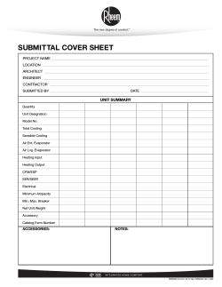


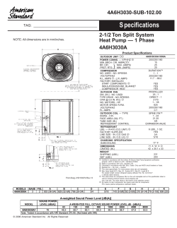
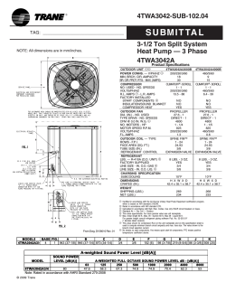


© Copyright 2026