
CHAPTER 5 SOIL NAIL WALLS - Courses Web Pages
Middle East Technical University
Civil Engineering Department
CE 468 Geotechnical Design
Chapter 5: Soil Nail Walls
This chapter is a short summary of “FHWA-IF-03-017-Geotechnical Engineering Circular No7_Soil Nail
Walls Manual(2003)”. Please refer to the technical report for more detailed information and references.
CHAPTER 5
SOIL NAIL WALLS
5.1. Applications and Feasibility Evaluations
Soil nailing consists of the passive reinforcement (i.e., no post-tensioning) of existing ground by
installing closely spaced steel bars (i.e., nails), which are subsequently encased in grout. Soil nailing is
typically used to stabilize existing slopes or excavations where top-to-bottom construction is
advantageous compared to other retaining wall systems.
Soil nails that are installed with a near horizontal orientation (i.e., inclination of 10 to 20 degrees
below horizontal) and are primarily subjected to tensile stresses.
A structure can be characterized as temporary or permanent by its service life or intended duration of
use. A structure with a service life of 18 months or less qualifies as temporary; a structure with a
longer service life qualifies as permanent. Depend on the temporary/permanent design factor of safety
values differs.
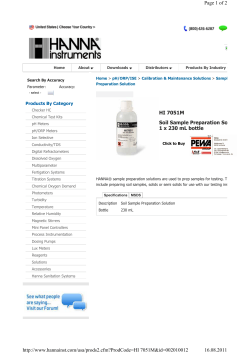
5.2. Basic Elements of a Soil Nail Wall
The most common practice for soil nailing consists of drilled soil nails, in which a steel bar is placed
in a pre-drilled hole and then grouted (Figure 5.1).
(a)
Dr. Zeynep ÇEKİNMEZ
Page 1/25
Middle East Technical University
Civil Engineering Department
CE 468 Geotechnical Design
Chapter 5: Soil Nail Walls
(b)
Figure 5.1. Typical cross-section of a soil nail wall (FHWA, 2003)
(a) Steel reinforcing bars – The solid steel reinforcing bars are the main component of the soil nail
wall system. These elements are placed in pre-drilled drillholes and grouted in place. Tensile stress is
applied passively to the nails in response to the deformation of the retained materials during
subsequent excavation activities. Steel reinforcing bars used for soil nails are commonly threaded and
may be either solid or hollow. Bars generally have a nominal tensile strength of 420 MPa [60 kips per
square inch (ksi) or Grade 60] or 520 MPa (75 ksi or Grade 75). Threaded bars for typical soil nail
wall applications are available in 26, 28, 30 and 32 mm diameter up to approximately 18 m (59 ft) in
length.
(b) Grout – Grout is placed in the pre-drilled borehole after the nail is placed. The grout serves the
primary function of transferring stress from the ground to the nail. The grout also provides a level of
corrosion protection to the soil nail. The water/cement ratio for grout used in soil nailing applications
typically ranges from 0.4 to 0.5. In some cases, a stiffer grout with a slump on the order of 30 mm (1½
in.) may be used. The need for a stiffer grout may arise when the hollow-stem auger drilling method is
used or it is desired to control leakage of grout into highly permeable granular soils or highly fractured
rock. The characteristics of the grout have a strong influence on the ultimate bond strength at groutground interface. Commonly, a minimum 28-day unconfined compressive strength of 21 MPa (3,000
psi) is specified for the grout.
(c) Nail head – The nail head is the threaded end of the soil nail that protrudes from the wall facing.
(d) Hex nut, washer, and bearing plate – These components attach to the nail head and are used to
connect the soil nail to the facing. The bearing plate is made of Grade 250 MPa (Grade 36) (ASTM
A36) steel and is typically square, 200- to 250-mm (8- to 10-in.) side dimension and 19-mm (¾-in.)
thick. The purpose of the bearing plate is to distribute the force at the nail end to the temporary
Dr. Zeynep ÇEKİNMEZ
Page 2/25
Middle East Technical University
Civil Engineering Department
CE 468 Geotechnical Design
Chapter 5: Soil Nail Walls
shotcrete facing and the ground behind the facing. The bearing plate has a central hole, which is
inserted over the nail bar. Beveled washers are then placed and the nail bar is secured with a hex nut or
with a spherical seat nut. Washers and nuts are steel with a grade consistent with that of the nail bar
commonly of 420 or 520 MPa (Grade 60 or 75). Nuts are tightened with a hand-wrench. The headstud
connection may consist of four headed studs that are welded near the four corners of the bearing plate
to provide anchorage of the nail head into the permanent facing.
(e) Centralizers – Centralizers are devices made of polyvinyl chloride (PVC) or other synthetic
materials that are installed at various locations along the length of each nail bar to ensure that a
minimum thickness of grout completely covers the nail bar. They are installed at regular ntervals,
typically not exceeding 2.5 m, along the length of the nail and at a distance of about 0.5 m from each
end of the nail.
(f) Temporary and permanent facing – The facing provides structural connectivity. The temporary
facing serves as the bearing surface for the bearing plate and support the exposed soil. This facing is
placed on the unsupported excavation prior to advancement of the excavation grades. The permanent
facing is placed over the temporary facing after the soil nails are installed and the hex nut has been
tightened.
(g) Geocomposite strip drainage – The geocomposite strip drainage systemmedia is placed prior to
application of the temporary facing to allow collection and transmission of seepage water that may
migrate to the temporary facing.
(h) Additional corrosion protection (not shown) in Figure 5.2.
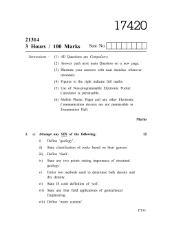
5.3. Construction Sequences
The typical sequence of construction for a soil nail wall using solid steel nail bars is described below
and shown schematically in Figure 5.2.
Step 1. Excavation: Initial excavation is carried out to a depth for which the face of the excavation has
the ability to remain unsupported for a short period of time, typically on the order of 24 to 48 hours.
The depth of the excavation lift is usually between 1 and 2 m and reaches slightly below the elevation
where nails will be installed.
The width of the excavated platform or bench must be sufficient to provide access to the installation
equipment.
Step 2. Drilling Nail Holes: Drillholes are drilled to a specified length, diameter, inclination, and
horizontal spacing from this excavated platform.
Step 3. Nail Installation and Grouting: Nail bars are placed in the pre-drilled hole. The bars are most
commonly solid, although hollow steel nails can be also used have seen increased usage. Centralizers
are placed around the nails prior to insertion to help maintain alignment within the hole and allow
sufficient protective grout coverage over the nail bar. A grout pipe (tremie) is also inserted in the
drillhole at this time. When corrosion protection requirements are high, corrugated plastic sheathing
Dr. Zeynep ÇEKİNMEZ
Page 3/25
Middle East Technical University
Civil Engineering Department
CE 468 Geotechnical Design
Chapter 5: Soil Nail Walls
can also be used to provide an additional level of corrosion protection. The drillhole is then filled with
cement grout through the tremie pipe. The grout is commonly placed under gravity or low pressure. If
hollow self-drilling bars are used (only as temporary structures), the drilling and grouting take place in
one operation. Prior to Step 4 (facing placement), geocomposite drainage strips are installed on the
excavation face approximately midway between each set of adjacent nails. The drainage strips are then
unrolled to the next wall lift. The drainage strips extend to the bottom of the excavation where
collected water is conveyed via a toe drain away from the soil nail wall.
Step 4. Construction of Temporary Shotcrete Facing. A temporary facing system is then constructed
to support the open-cut soil section before the next lift of soil is excavated. The most typical temporary
facing consists of a lightly reinforced shotcrete layer commonly 100 mm (4 in.) thick. The
reinforcement typically consists of welded wire mesh (WWM), which is placed at approximately the
middle of the facing thickness (Figure 5.1(a)). The length of the WWM must be such that it allows at
least one full mesh cell to overlap with subsequent WWM panels. Following appropriate curing time
for the temporary facing, a steel bearing plate is placed over the nail head protruding from the
drillhole. The bar is then lightly pressed into the first layer of fresh shotcrete. A hex nut and washers
are subsequently installed to secure the nail head against the bearing plate. The hex nut is tightened to
a required minimum torque after the temporary facing has sufficiently cured. This usually requires a
minimum of 24 hours. If required, testing of the installed nails to measure deflections (for comparison
to a pre-specified criterion) and proof load capacities may be performed prior to proceeding with the
next excavation lift. Before proceeding with subsequent excavation lifts, the shotcrete must have cured
for at least 72 hours or have attained at least the specified 3-day compressive strength [typically 10.5
MPa (1,500 psi).
Step 5. Construction of Subsequent Levels. Steps 1 through 4 are repeated for the remaining
excavation lifts. At each excavation lift, the vertical drainage strip is unrolled downward to the
subsequent lift. A new panel of WWM is then placed overlapping at least one full mesh cell. The
temporary shotcrete is continued with a cold joint with the previous shotcrete lift. At the bottom of the
excavation, the drainage strip is tied to a collecting toe drain.
Step 6. Construction of a Final, Permanent Facing. After the bottom of the excavation is reached
and nails are installed and load tested, a final facing may be constructed. Final facing may consist of
cast-in-place (CIP) reinforced concrete, reinforced shotcrete, or prefabricated panels. The
reinforcement of permanent facing is conventional concrete bars or WWM. When CIP concrete and
shotcrete are used for the permanent facing, horizontal joints between excavation lifts are avoided to
the maximum extent possible.
Variations of the steps described above may be necessary to accommodate additional preparation tasks
or supplementary activities for specific project conditions. For example, shotcrete may be applied at
each lift immediately after excavation and prior to nail hole drilling and installation, particularly where
face stability is a concern.
Dr. Zeynep ÇEKİNMEZ
Page 4/25
Middle East Technical University
Civil Engineering Department
CE 468 Geotechnical Design
Chapter 5: Soil Nail Walls
Figure 5.2. Typical soil nail wall construction sequence (FHWA, 2003)
5.4. Applications of Soil Nail Walls
Soil nail walls are particularly well suited to excavation applications for ground conditions that require
vertical or near-vertical cuts. They have been used successfully in highway cuts; end slope removal
under existing bridge abutments during underpass widening; for the repair, stabilization, and
reconstruction of existing retaining structures; and tunnel portals. Soil nail walls have been shown to
be particularly well suited in the following temporary or permanent applications:
•
roadway cut excavations;
Dr. Zeynep ÇEKİNMEZ
Page 5/25
Middle East Technical University
Civil Engineering Department
•
•
CE 468 Geotechnical Design
Chapter 5: Soil Nail Walls
Figure 5.3. Soil nail walls for temporary and permanent cut slopes (FHWA, 2003)
repair and reconstruction of existing retaining structures; and
road widening under an existing bridge end;
Soil nail walls can be advantageous for underpass widening by removal of an existing bridge
abutment end slope (see Figure 5.4) when compared to conventional ground anchor supported walls.
Soil nail walls can be installed at comparable costs; however, the installation of soil nail walls does
not require that bridge traffic be interrupted. If a ground anchor supported wall is used, soldier beams
would have to be installed through the bridge deck because of limited overhead space under the
bridge prior to excavating the end slope abutment. This operation results in the disruption of overpass
traffic and accrues additional costs associated with lane closures and the procurement of large steel
beams. Conversely, steel reinforcing bars used as soil nails are readily available. One disadvantage of
the use of soil nail walls for end slope removal projects is that because the first level of soil nails is
typically placed within 1 to 2 m (3 to 6 ft) from the top of the slope and because the nails are sloped
downward, it is possible that the bridge girders will interfere with soil nail installation. This problem
Dr. Zeynep ÇEKİNMEZ
Page 6/25
Middle East Technical University
Civil Engineering Department
CE 468 Geotechnical Design
Chapter 5: Soil Nail Walls
can usually be avoided by positioning the soil nails horizontally to be within the clear space between
bridge girders.
Figure 5.4. Road widening under existing bridge (FHWA, 2003)
•
temporary or permanent excavations in an urban environment.
5.5. Feasibility Evaluation of Soil Nail Walls
The feasibility evaluation of a soil nail wall should encompass technical and economic considerations
and include: (1) an evaluation of the prevailing ground conditions; (2) an assessment of the advantages
and disadvantages of a soil nail wall for the particular application being considered; (3) comparison
with alternative systems (e.g., ground anchor wall systems); and (4) evaluation of costs.
The following sections present a discussion of these aspects of the feasibility evaluation.
5.5.1. Evaluation of Ground Conditions for Soil Nail Walls
Soil nail walls can be used for a wide range of soil types and conditions. The following two sections
present the soil conditions that are considered most and least suitable for soil nail walls.
5.5.1.1. Favorable Soil Conditions for Soil Nailing
Soil nail walls have been constructed successfully in various types of soils. Construction difficulties
and long-term complications can generally be avoided when specific favorable soil conditions prevail.
Soil nailing has proven economically attractive and technically feasible when:
•
•
the soil in which the excavation is constructed is able to stand unsupported in a 1- to 2-m high
vertical or nearly vertical cut for one to two days;
all soil nails within a cross section are located above the groundwater table; and
Dr. Zeynep ÇEKİNMEZ
Page 7/25
Middle East Technical University
Civil Engineering Department
•
CE 468 Geotechnical Design
Chapter 5: Soil Nail Walls
if the soil nails are below the groundwater table, the groundwater does not adversely affect the
face of the excavation, the bond strength of the interface between the grout and the
surrounding ground, or the long-term integrity of the soil nails (e.g., the chemical
characteristics of the ground do not promote corrosion).
Although not an absolute requirement, it is advantageous that the ground conditions allow drillholes
to be advanced without the use of drill casings and for the drillhole to be unsupported for a few hours
until the nail bars are installed and the drillhole is grouted.
Soil conditions are presumed to be favorable for the construction of soil nail walls when results from
field tests indicate competent soils. The Standard Penetration Test provides the SPT value, N, which
can be used to preliminarily identify favorable soil conditions. Based on the general criteria for
favorable conditions noted above, the following ground types are generally considered well suited for
soil nailing applications.
•
•
•
•
Stiff to hard fine-grained soils. Fine-grained (or cohesive) soils may include stiff to hard
clays, clayey silts, silty clays, sandy clays, sandy silts, and combinations thereof. Fine-grained
soils can be tentatively classified as stiff if they have SPT N-values of at least 9 blows/300
mm (blows/ft). However, the consistency characterization of fine-grained soils should not rely
solely on SPT N-values. Instead, the consistency (and thereby shear strength) characterization
should be supplemented with other field and/or laboratory testing. To minimize potential longterm lateral displacements of the soil nail wall, fine grained soils should be of relatively low
plasticity [i.e., in general, plasticity index (PI) < 15].
Dense to very dense granular soils with some apparent cohesion. These soils include sand
and gravel with SPT N-values larger than 30 (Terzaghi et al., 1996), and with some fines
(typically no more than about 10 to 15 percent of fines) or with weak natural cementation that
provide cohesion. Capillary forces in moist fine sands may also provide an apparent cohesion.
In general, the apparent cohesion for these soils should be greater than 5 kPa (100 psf) to
assure reasonable stand-up times. To avoid excessive breakage of capillary forces and thereby
significant reduction of this apparent cohesion, the movement of water toward the excavation
face needs to be minimized including by redirecting surface water away from the excavation
face.
Weathered rock with no weakness planes. Weathered rock may provide a suitable supporting
material for soil nails as long as weakness planes occurring in unfavorable orientations are not
prevalent (e.g., weakness planes dipping into the excavation). It is also desirable that the
degree of weathering be approximately uniform throughout the rock so that only one drilling
and installation method will be required. Conversely, a highly variable degree of rock
weathering at a site may require changes in drilling equipment and/or installation techniques
and thereby cause a costly and prolonged soil nail installation.
Glacial soils. Glacial outwash and glacial till materials are typically suitable for soil nailing
applications as these soils are typically dense, well-graded granular materials with a limited
amount of fines.
Dr. Zeynep ÇEKİNMEZ
Page 8/25
Middle East Technical University
Civil Engineering Department
CE 468 Geotechnical Design
Chapter 5: Soil Nail Walls
5.5.1.2. Unfavorable or Difficult Soil Conditions for Soil Nailing
Examples of unfavorable soil types and ground conditions are provided below:
•
Dry, poorly graded cohesionless soils. When poorly graded cohesionless soils are completely
dry, contain no fines, or do not exhibit any natural cementation, apparent cohesion is not
available. Therefore, the required vertical or nearly vertical cuts are difficult to achieve.
•
Soils with high groundwater. Perched groundwater occurring behind the proposed soil nail
wall will require significant drainage, which is necessary to stabilize the mass of soil in this
location. Additionally, large amounts of groundwater can cause drillholes (particularly in
loose granular soils) to collapse easily, thus requiring a costly soil nail installation. Excessive
groundwater seeping out to the excavation face may cause significant difficulties for shotcrete
application.
•
Soils with cobbles and boulders. A large proportion of cobbles and boulders present in the
soil may cause excessive difficulties for drilling and may lead to significant construction costs
and delays. When only a few boulders and cobbles are present, modifying the drilling
orientation from place to place may minimize or eliminate most of the difficult drilling.
However, this approach has practical limitations when too many boulders are present.
•
Soft to very soft fine-grained soils. These soils typically have SPT N-values less than 4 and
are unfavorable for soil nailing because they develop relatively low bond strengths at the nailgrout-soil interface, thereby requiring unreasonably long nail lengths to develop the required
resistance. Long-term deformations (creep) of the soils may be a concern for highly plastic
clays. Concerns for creep deformations are generally less critical for temporary applications.
As with any retaining system constructed in a top-down manner, the potential for instability at
the bottom of the excavation is high in soft fine-grained soils. Additionally, high-plasticity
soils may be expansive and may induce additional localized pressure on the facing due to
swelling.
•
Organic soils. Some organic soils such as organic silts, organic clays and peat typically
exhibit very low shear strengths and thereby low bond strengths, which causes uneconomical
nail lengths. While some organic soils can exhibit acceptable shear strengths, other organic
soils like fibrous peat may be highly heterogeneous and highly anisotropic. In this case, while
the soil shear strength can be reasonable along some orientations, it may be significantly low
along other orientations. These unfavorable orientations may have a detrimental impact on the
wall stability and very long soil nails will be required. In addition, organic soils tend to be
more corrosive than inorganic soils.
•
Highly corrosive soil (cinder, slag) or groundwater. These conditions may lead to the need of
providing expensive corrosion protection. These conditions are obviously more
disadvantageous for permanent applications of soil nail walls.
Dr. Zeynep ÇEKİNMEZ
Page 9/25
Middle East Technical University
Civil Engineering Department
CE 468 Geotechnical Design
Chapter 5: Soil Nail Walls
•
Weathered rock with unfavorable weakness planes and karst. Weathered rock with prevalent
unfavorable weakness planes such as joints, fractures, shears, faults, bedding, schistosity, or
cleavage may affect the drillhole stability and make grouting difficult. In addition, the
presence of these discontinuities may cause the formation of potentially unstable blocks in the
retained mass behind the wall during excavation. The marginal stability of blocks may rapidly
deteriorate due to various factors, such as gouge in the joints, uplift and lateral hydrostatic
pressures, and seepage forces. The stabilization of individual blocks may be necessary and can
make this solution uneconomical when compared to conventional soil nails. In addition,
grouting in rock with very large open joints or voids will be very difficult and/or expensive
due to excessive grout loss. Grouting in karstic formations is not appropriate.
•
Loess. When it is dry, loess may exhibit acceptable strengths that would allow economical
installation of soil nails. However, when sizable amounts of water ingress behind the proposed
soil nail wall, the structure of the loess may collapse and a significant loss of soil strength may
take place. Therefore, the collapse potential upon wetting of these soils must be evaluated.
Appropriate measures to avoid excess water migration to the soil nail area must be provided in
loess exhibiting significant collapse potential. Additionally, considerably low soil shear
strengths may arise for the wetted condition. In these cases, unusually long soil nail lengths
may result in using conventional methods of nail installation. Regrouting (an atypical and
more costly step) has been used to increase bond strengths in loess.
In addition to the difficulties described above, other aspects related to soil conditions must be
considered when assessing the feasibility of soil nail walls:
•
•
•
•
The prolonged exposure to ambient freezing temperatures may cause frost action in saturated,
granular soils and silt; as a result, increased pressures will be applied to the temporary and
permanent facings.
Repeated freeze-and-thaw cycles taking place in the soil retained by the soil nail wall may
reduce the bond strength at the soil nail grout-ground interface and the adhesion between the
shotcrete and the soil. To minimize these detrimental effects, a suitable protection against frost
penetration and an appropriate shotcrete mix must be provided.
Granular soils that are very loose (N ≤ 4) and loose (4 < N ≤ 10) may undergo excessive
settlement due to vibrations caused by construction equipment and traffic.
Loose and very loose saturated granular soil can be susceptible to liquefaction in seismically
exposed regions. Several ground modification techniques (typically with significant associated
costs) may be utilized to densify granular soils and thereby minimize these damaging effects.
Despite the difficulties associated with unfavorable soil conditions described above, soil nail
walls may still be built. It should be recognized that these wall systems would typically be
more expensive to design and construct when compared to conventional walls in a more
suitable soil. It is likely that significant extra effort and cost is needed in the design and
construction of soil nail walls in these marginal conditions and that more strict long-term
performance requirements might be necessary to allow soil nailing in such challenging
conditions.
Dr. Zeynep ÇEKİNMEZ
Page 10/25
Middle East Technical University
Civil Engineering Department
CE 468 Geotechnical Design
Chapter 5: Soil Nail Walls
5.5.1.3. Intermediate Soil Conditions for Soil Nailing
There exists some soil conditions that are intermediate to the two conditions described previously.
Although, the engineering properties are less favorable than those described in Section 5.5.1.1, soil
nail walls have been installed successfully and cost-efficiently in certain intermediate soil conditions.
Examples of intermediate soil conditions are presented below:
•
•
Engineered fill. Soil nails can be installed in engineered fill if it is a mixture of wellgraded
granular material (approximately 90 percent of the mix or more) and fine-grained soil with
low plasticity (typically, PI < 15).
Residual soils. Residual soils (i.e., those soils created from the in-place weathering of the
parent rock material) may be an acceptable material for soil nailing. Similarly, lateritic soil, a
highly weathered tropical soil, may be acceptable. For these types of soil, specific
consideration should be given to the soil spatial variability and its ability to drain.
5.5.2. Advantages and Disadvantages of Soil Nail Walls
Advantages
Less disruptive to traffic and causes less
environmental impact compared to other
construction techniques
There is no need to embed any structural element
below the bottom of excavation as with soldier
beams used in ground anchor walls
Disadvantages
Soil nail walls may not be appropriate for
applications where very strict deformation control
is required for structures and utilities located
behind the proposed wall, as the system requires
some soil deformation to mobilize resistance
Soil nail walls are not well-suited where large
amounts of groundwater seeps into the excavation
because of the requirement to maintain a
temporary unsupported excavation face
Installation of soil nail walls is relatively rapid
and uses typically less construction materials than
ground anchor walls
Easy adjustments of nail inclination and location
can be made when obstructions (e.g., cobbles or
boulders, piles or underground utilities) are
encountered; on the other hand, the horizontal
position of ground anchors is more difficult to
modify almost making adjustments in the field
costly
Soil nailing is advantageous at sites with remote
access because smaller equipment is generally
needed
Soil nail walls are relatively flexible and can
accommodate relatively large total and
differential settlements
Measured total deflections of soil nail walls are
usually within tolerable limits
Soil nail walls have performed well during
seismic events owing to overall system flexibility
Dr. Zeynep ÇEKİNMEZ
Page 11/25
Middle East Technical University
Civil Engineering Department
CE 468 Geotechnical Design
Chapter 5: Soil Nail Walls
5.6. Bond Strength
The pullout capacity of a soil nail installed in a grouted nail hole is affected by the size of the nail (i.e.,
perimeter and length) and the ultimate bond strength, 𝑞𝑢 . The bond strength is the mobilized shear
resistance along the soil-grout interface. The bond strength is rarely measured in the laboratory and
there is no standard laboratory testing procedure that can be used to evaluate bond strength. Therefore,
designs are typically based on conservative estimates of the bond strength obtained from field
correlation studies and local experience in similar conditions. As a result of this dependency on local
conditions, contract specifications include a strict requirement that some percentage of the soil nails be
load tested in the field to verify bond strength design.
From experience, it is known that for drilled and grouted nails, the bond strength is affected by:
•
•
•
ground conditions around the nail (soil type and conditions);
soil nail installation including:
o drilling method;
o grouting procedure;
o grout nature;
o grout injection (e.g.; gravity or under pressure); and
the size of the grouted zone.
For drilled and grouted nails in cohesionless soil, the magnitude of the overburden pressure and the
nature of the granular soil affect the soil friction angle, which in turn affects the bond strength. For
grouted nails in fine-grained soil, the bond strength is in general a fraction of the undrained shear
strength of the soil. In general, the bond strength increases (but not linearly) with the undrained shear
strength of the soil. For softer soils, the ratio of bond strength to the soil undrained shear strength,
𝑞𝑢 ⁄𝑐𝑢 , is higher than for stiffer soils.
Typical values of ultimate bond for drilled and grouted nails installed in various soils and using
different drilling methods are presented in Table 5.1. This table allows the designer to estimate bond
strengths by entering the name of common rock types and soils described by their geologic origin
(e.g., colluvium, moraine, etc.). Although Table 5.1 covers a wide variety of rock/soil types, drilling
methods, and ground conditions, the database used to develop the table does not cover all the possible
case combinations. The lower and upper bounds contained in Table 5.1 correspond approximately to
the least and most favorable conditions for a particular soil type and construction method. For
example, in the case of granular soils, for which the ranges are relatively broad, the lower and upper
bonds may correspond to conditions of loose and very dense materials, respectively. These values
inherently contain some level of conservatism and can be used as preliminary values for design. The
ultimate bond strength in soil may be estimated in the field during the site investigation phase of the
project from the results of PMT (not commonly used in the United States), using the following
correlation:
𝑞𝑢 (𝑘𝑘⁄𝑚2 ) = 14𝑃𝐿 (𝑀𝑀⁄𝑚2 )[6 − 𝑃𝐿 (𝑀𝑀⁄𝑚2 )]
where 𝑃𝐿 is the limit pressure recorded in MN/m2 as measured with the pressuremeter, and 𝑞𝑢 is the
Dr. Zeynep ÇEKİNMEZ
Page 12/25
Middle East Technical University
Civil Engineering Department
CE 468 Geotechnical Design
Chapter 5: Soil Nail Walls
ultimate bond strength calculated in kPa.
In the case of rocks, the bond strength can also be estimated from correlations with the compressive
strength of intact rock. The Post-Tensioning Institute (PTI, 1996) alternatively suggests that the
ultimate bond stress between rock and grout can be approximated as 10 percent of the unconfined
compressive strength of the rock up to a maximum of 4,000 kPa (600 psi). However, it is
recommended that estimates of bond strengths do not exceed the values for typical rocks contained in
Table 5.1.
Because of the difficulty in estimating bond strength, it is common practice to require pre-production
soil nail load tests to verify the bond strengths included in construction specifications and establish the
minimum required nail length to support a specified nail design load.
Table 5.1. Estimated bond strength of soil nail (FHWA, 2003)
Dr. Zeynep ÇEKİNMEZ
Page 13/25
Middle East Technical University
Civil Engineering Department
CE 468 Geotechnical Design
Chapter 5: Soil Nail Walls
5.7. Analysis of Soil Nail Walls
5.7.1. Load Transfer Concept in Soil Nail Walls
Figure 5.5. Potential failure surfaces and soil nail tensile forces
5.7.2. Limit States
The analysis and design of soil nail walls must consider two distinct limiting conditions: Strength
Limit States and the Service Limit States.
• Strength limit states. These limit states refer to failure or collapse modes in which the applied loads
induce stresses that are greater than the strength of the whole system or individual components, and
the structure becomes unstable. Strength limit states arise when one or more potential failure modes
are realized. The design of a soil nail wall should ensure that the system is safe against all of the
potential failure conditions presented in Figure 5.6 and classified as:
o
o
o
external failure mode;
internal failure mode; and
facing failure mode.
• Service limit states. These limit states refers to conditions that do not involve collapse, but rather
impair the normal and safe operation of the structure. The major service limit state associated with
soil nail walls is excessive wall deformation.
Dr. Zeynep ÇEKİNMEZ
Page 14/25
Middle East Technical University
Civil Engineering Department
CE 468 Geotechnical Design
Chapter 5: Soil Nail Walls
Figure 5.5. Principal modes of failure of soil nail wall systems
5.7.2.1. External Failure Modes
5.7.2.1.1. Global Stability Failure
Figure 5.6. Global stability analysis of soil nailing wall using a single-wedge failure mechanism
Dr. Zeynep ÇEKİNMEZ
Page 15/25
where:
D =
E =
I’ =
c’ =
\ =
i =
LF =
W =
QT =
TEQ=
NF =
SF =
Rc =
RI =
wall face batter angle (from vertical);
slope angle;
soil effective angle of internal friction;
soil effective cohesion;
inclination of failure plane;
nail inclination;
length of failure plane;
weight of sliding mass;
surcharge load;
equivalent nail force;
normal force on failure surface;
shear force on failure surface;
cohesive component of SF; and
frictional component of SF.
The destabilizing forces consist of the driving components of the weight (W) and the surcharge
loads (Q). The stabilizing forces along the failure surface are the shear force (SF) and the equivalent
nail tensile force (TEQ). It is noted that the force TEQ is a resultant force that combines the effect of
all nails installed to that depth H. The factor of safety against global failure (FSG) is expressed as
the ratio of the resisting and driving forces, which act tangent to the potential failure plane:
FSG
¦ resisting forces
¦ driving forces
(Equation 5.1)
The normal and tangent forces on the failure plane are:
¦ Normal Forces (W Q ) cos ȥ T
¦Tangent Forces (W Q ) sin ȥ T
T
T
EQ cos (ȥ
i) N F
0
(Equation 5.2)
EQ sin (ȥ
i) SF
0
(Equation 5.3)
where:
SF
Rc Rf
c m Ls N F tan Im
tanIm
cm
tanI'
FSG
c'
FSG
(Equation 5.4)
(Equation 5.5)
(Equation 5.6)
and Im is the mobilized friction angle, and cm is the mobilized cohesion. A single global factor of
safety is used for the cohesive and frictional strength components of the soil (c’ and tanI’,
respectively). However, it is possible to select different safety factors for each strength component.
70
made slopes, embankments. Section 5.9 presents discussions of the basis of values of safety factors
in soil nail wall systems and provides recommended minimum values of FSG, as well as safety
factors for other failure modes.
5.4.3
Sliding
Sliding stability analysis considers the ability of the soil nail wall to resist sliding along the base of
the retained system in response to lateral earth pressures behind the soil nails. Sliding failure may
occur when additional lateral earth pressures, mobilized by the excavation, exceed the sliding
resistance along the base (Figure 5.5).
Concepts similar to those used to assess sliding stability of gravity retaining structures (in which
Rankine or Coulomb theories of lateral earth pressures are used) can be applied to assess the sliding
stability of a soil nail wall system. Again, the soil nail wall system is modeled as a rigid block
against which lateral earth forces are applied behind the retained soil. The rigid block here is
defined by a nearly horizontal surface through the base of the wall (or slightly below the base, if a
weak, horizontal seam of soil is present), extends behind the nails, and exits with a steep angle at
the ground surface behind the reinforced zone (Figure 5.5). It is assumed that the displacements of
the soil block along its base are large enough to mobilize the active pressure behind the block. The
factor of safety against sliding (FSSL) is calculated as the ratio of horizontal resisting forces (6R) to
the applied driving horizontal forces (6D) as follows:
¦R
¦D
FSSL
where:
¦R
c b BL W Q D PA sin ȕ tan Ib
¦D
PA cos ȕ
(Equation 5.7)
(Equation 5.8)
(Equation 5.9)
The active lateral earth force (PA) is defined as:
PA
Ȗ H 12
KA
2
(Equation 5.10)
The terms in the equations above and in Figure 5.5 are identified as follows:
H = wall height;
'H = slope rise up to bench (if present);
ȕ = backslope angle;
ȕeq = equivalent backslope angle [for broken slopes ȕeq = tan-1('H/H), for infinite slopes ȕeq = ȕ];
D = face batter angle;
T = inclination of wall face from horizontal (i.e., T = D + 90Û);
cb = soil cohesion strength along the base;
BL = length of the horizontal failure surface where cb is effectively acting;
W = weight of soil nail block;
QD = permanent portion of total surcharge load QT;
72
I’b = effective angle of internal friction of the base (remolded or residual values may be needed if
significant movement takes place);
I’ = effective friction angle of soil behind soil nail block;
į = wall-soil interface friction angle [for a broken slope, į = ȕeq, for infinite slope, į = ȕ];
Ȗ = total unit weight of soil mass;
H1 = effective height over which the earth pressure acts [H1 = H + (B + tan D) tan ȕeq]; and
KA = active earth pressure coefficient for soil behind the soil nail wall system.
QT
2H
For infinite slopes:
'H
E
Eeq
For broken slopes:
Eeq = E
'H
Eeq = tan-1(2H
)
1
JI', c' = 0
W
D
H1
PA
G Eeq
H
H/3
T
BL
Strength parameters
cb and I'b
6R
Figure 5.5: Sliding Stability of a Soil Nail Wall.
The active earth pressure coefficient, KA, can be obtained using the formulation derived from the
general Coulomb theory or the Rankine theory for cohesionless soil (assuming that the soil behind
the soil nail wall behaves in accordance with c’= 0 in the long-term loading condition).
According to the Coulomb theory:
KA
sin 2 (ș I' )
ª
sin(I į) sin(I'ȕ) º
sin 2 ș sin (ș į) «1 »
sin(ș į) sin(ș ȕ) ¼
¬
where the parameters have been defined previously.
73
2
(Equation 5.11)
The Rankine theory provides, for walls with face batter angles D < 8 degrees and dry, sloping
ground behind the wall, the coefficient of active earth pressure as:
KA
ª cos ȕ - cos 2 ȕ - cos 2 I' º
»
cos ȕ «
«¬ cos ȕ cos 2 ȕ - cos 2 I' »¼
(Equation 5.12)
For the simple case of a vertical wall (i.e., D = 0 or T = 90Û), with dry, horizontal ground (i.e., E = 0)
behind the wall, and no shear stresses on the wall-soil interface (i.e., į = 0), the Rankine theory
provides the coefficient of active earth pressure simply as the well-known expression:
KA
I' ·
§
tan 2 ¨ 45 ¸
2¹
©
(Equation 5.13)
Equation 5.11 from the Coulomb theory is more general than Equation 5.12 from the Rankine
theory. Both theories provide solutions that are approximately equivalent. Equation 5.13 is very
simple and should be used only to provide preliminary values.
For non-vertical wall facings, the active earth pressure coefficient defined by Equation 5.12 can be
estimated from charts presented in Figures 5.6 and 5.7 (Caquot and Kerisel, 1948; U.S. Navy,
1982). In these figures, a different nomenclature is used and the wall face batter angle is identified
as “T”, instead of D. Figure 5.6 considers the effect of various wall face inclinations with a
horizontal backslope and a wall-soil friction angle į = I’. The batter angle “T” in Figure 5.6 can be
a positive value (overhanging wall) or a negative value (conventional battered walls). From this
figure, it is noted that the active earth coefficient decreases as the wall becomes flatter (face batter
angle “T” becomes more negative), which confirms that intuitively a “flatter wall” is more stable
with all other conditions being unchanged. Figure 5.7 takes into account the effect of backslope
angle for a vertical wall face and a wall-soil friction angle į = I’. Figure 5.7 clearly shows that the
magnitude of the active coefficient grows significantly as the slope angle increases. The charts
developed by Caquot and Kerisel are recommended as they rely on more realistic failure surfaces
(i.e., log spiral failure surface). The factor of safety against sliding can also be calculated using
standard slope stability computer programs. In such cases, the failure surfaces used in computer
analysis must be non-circular, have a relatively long, nearly horizontal segment, and be forced to
pass through the base of the wall.
5.4.4
Bearing Capacity
Although not very often, bearing capacity may be a concern when a soil nail wall is excavated in
fine-grained, soft soils. Because the wall facing does not extend below the bottom of the excavation
(unlike soldier piles in cantilever or ground anchor walls), the unbalanced load caused by the
excavation may cause the bottom the excavation to heave and trigger a bearing capacity failure of
the foundation (Figure 5.8a).
74
Source: U.S. Navy (1982).
Figure 5.6: Effect of Wall Batter Angle on the Active Earth Coefficient.
Source: U.S. Navy (1982).
Figure 5.7: Effect of Backslope Angle on the Active Earth Coefficient.
75
Load expressed as
equivalent soil
overburden: J'H
B'
Be
(width of excavation is typically very large)
J'H
DB
HB'
HB'
Su H
soft
fine-grained
soil
H
Su H
H
soft
fine-grained
soil
Be / 2
DB
Failure surface
b) Shallow deposit of soft fine-grained soil
underlain by stiff layer
a) Deep deposit of soft fine-grained soil
10
Be/L = 1, Square
and Circular
9
Be/L = 0.5
H = Excavation depth
Be = Excavation width
Le = Excavation Length
8
NC
7
Be/L = 0, Rectangular
6
5
4
0
1
2
3
4
5
H/Be
c) Bearing Capacity Factor, NC
Source: Terzaghi, et al. (1996).
Figure 5.8: Bearing Capacity (Heave) Analysis.
Equations to assess heave potential at the bottom of excavations can be used to analyze this failure
mode. The factor of safety against heave (FSH) (Terzaghi et al., 1996), is:
FSH
Su N c
S ·
§
H eq ¨ J u ¸
B' ¹
©
where these terms and the terms in Figure 5.8 are defined as:
Su
Nc
Ȗ
H
=
=
=
=
undrained shear strength of the soil;
bearing capacity factor (Figure 5.8);
unit weight of the soil behind wall;
height of the wall;
76
(Equation 5.14)
Heq = equivalent wall height = H+'H, with 'H is an equivalent overburden; and
B’ = width of influence, B’ = Be/ 2 , where Be = width of excavation.
The bearing capacity factor must be adopted based on the existing geometric conditions. For
excavations very wide excavations (typical case for a soil nail wall), H/ Be can be considered
conservatively equal to 0. For very long walls, it is conservative to adopt Be / Le = 0, and Nc =5.14.
When a strong deposit underlying the soft layer and occurring at a depth DB < 0.71 Be below the
excavation bottom is encountered (Figure 5.8b), B’ in Equation 5.14 must be replaced by DB.
When the width of the excavation is very large or the contribution of the shearing resistance (i.e.,
Su H) outside the failure block of width B’ is neglected, equation 5.14 becomes conservatively
FSH = Nc/ J Heq. These equations are conservative because they neglect the shear contribution of
the nails that are intersected by the failure surface shown in Figure 5.8a and 5.8b.
Equivalent bearing capacity analyses may also be performed using slope stability analysis programs
that consider deep-seated failure surfaces through the foundation, similar to the ones shown in
Figure 5.8. Bearing capacity analyses are routinely not necessary for cases where soft soils [e.g., Su
25 (kPa) 500 psf] are not present at the bottom of the excavation. An exception to this general
rule-of-thumb is when large loads are imposed behind the proposed soil nail wall. For this case, a
bearing capacity analysis is recommended regardless of the soil conditions.
Factors of safety against heave for soil nail walls should be selected to be consistent with those
typically used for heave analysis at the bottom of excavations. In general, FSH can be adopted as
2.5 and 3 for temporary and permanent walls, respectively. As the great majority of soil nail walls
are not constructed in soft fine-grained soils, this failure mode is not critical for most soil nail
projects.
5.4.5
Seismic Considerations in Soil Nail Wall Stability
5.4.5.1 Introduction
The evaluation of seismic effects on the stability of soil nail walls is of primary importance in areas
with high seismic exposure. Soil nail walls have performed remarkably well during strong ground
motions, in contrast to the generally poor performance of gravity retaining structures. After the
1989 Loma Prieta, California; 1995 Kobe, Japan; and 2001 Nisqually, Washington earthquakes, it
was reported that soil nail walls showed no sign of distress or significant permanent deflection,
despite having experienced, in some cases, ground accelerations as high as 0.7g (Felio et al., 1990;
Tatsuoka et al., 1997; and Tufenkjian, 2002). These observations indicate that soil nail walls appear
to have an inherent satisfactory seismic response. This has been attributed to the intrinsic flexibility
of soil-nailed systems (comparable to that of other flexible retaining systems such as MSE walls)
and possibly to some levels of conservatism in existing design procedures. Similar trends have
been obtained from centrifuge tests performed on reduced-scale models of soil nail walls [(e.g.,
Vucetic et al. (1993), Tufenkian and Vucetic (2000)]. The following three sections discuss some of
the analyses needed to assess seismic effects on global and sliding stability.
77
Middle East Technical University
Civil Engineering Department
CE 468 Geotechnical Design
Chapter 5: Soil Nail Walls
5.7.2.2. Internal Failure Modes
5.7.2.2.1. Nail Pull-Out Failure
Pullout failure is the primary internal failure mode in a soil nail wall. This failure mode may occur
when the pullout capacity per unit length is inadequate and/or the nail length is insufficient. In general,
the mobilized pullout per unit length, 𝑄, (also called the load transfer rate) can be expressed as:
𝑄 = 𝜋𝑞𝐷𝐷𝐷
Where; 𝑞: mobilized shear stress acting around the perimeter of the nail-soil interface; and
𝐷𝐷𝐷 : average or effective diameter of the drill hole.
When mobilized pullout per length reaches to its maximum value (𝑄𝑢 ) depending on the bond strength
(𝑞𝑢 ), the ultimate pull-out capacity (𝑇𝑚𝑚𝑚 ) is fulfilled.
𝑄𝑢 = 𝜋𝑞𝑢 𝐷𝐷𝐷
Where; 𝐿𝑝 : pullout length.
Dr. Zeynep ÇEKİNMEZ
𝑇𝑚𝑚𝑚 = 𝑄𝑢 𝐿𝑝
Page 23/25
Middle East Technical University
Civil Engineering Department
CE 468 Geotechnical Design
Chapter 5: Soil Nail Walls
5.7.2.2.2. Nail Tensile Failure
A tensile failure of a soil nail takes place when the longitudinal force along the soil nail is
greater than the nail bar tensile capacity (𝑅𝑇 ), which is defined as:
𝑅𝑇 = 𝑓𝑦 𝐴𝑡
Where; 𝑓𝑦 : nail bar yield strength and 𝐴𝑡 : nail bar cross-sectional area.
5.8. Factor of Safeties
5.9. Wall Displacements
During construction and after its completion, a soil nail wall and the soil behind it tend to deform
outwards. The outward movement is initiated by incremental rotation about the toe of the wall, similar
to the movement of a cantilever retaining wall. Most of the movement occurs during or shortly after
excavation of the soil in front of the wall. Post construction deformation is related to stress relaxation
and creep movement, which are caused by post-construction moderate increases in tensile force in the
soil nail described previously. Maximum horizontal displacements occur at the top of the wall and
decrease progressively toward the toe of the wall. Vertical displacements (i.e., settlements) of the wall
at the facing are generally small, and are on the same order of magnitude as the horizontal movements
at the top of the wall. In general, horizontal and vertical displacements of the facing depend on the
following factors:
•
•
•
•
wall height, H, (deformation increases approximately linearly with height);
wall geometry (a vertical wall produces more deformation than a battered wall);
the soil type surrounding the nails (softer soil will allow more deformation);
nail spacing and excavation lift heights (larger nail spacing and thicker incremental excavation
lifts generate more deformation);
Dr. Zeynep ÇEKİNMEZ
Page 24/25
Middle East Technical University
Civil Engineering Department
•
•
•
CE 468 Geotechnical Design
Chapter 5: Soil Nail Walls
global factor of safety (smaller FSG’s are associated with larger deformation);
nail-length-to wall-height ratio (shorter nail lengths in relation to the wall height generates
larger horizontal deformation);
nail inclination (steeper soil nails tend to produce larger horizontal deformation because of
less efficient mobilization of tensile loads in the nails); and magnitude of surcharge
(permanent surcharge loading on the wall increases deformation).
Empirical data show that for soil nail walls with typical L/H between 0.7 and 1.0, negligible surcharge
loading, and typical global factors of safety (FSG) values of 1.5, the maximum long-term horizontal
and vertical wall displacements at the top of the wall, 𝛿ℎ and 𝛿𝑣 , respectively, can be estimated as
follows:
𝛿ℎ
𝛿ℎ = � � × 𝐻
𝐻 𝑖
Where; (𝛿ℎ /𝐻)𝑖 : a ratio dependant on the soil conditions “𝑖” indicated in the table below; and 𝐻 : wall
height.
The size of the zone of influence (Figure 5.5), where noticeable ground deformation may take place is
defined by a horizontal distance behind the soil nail wall (𝐷𝐷𝐷𝐷 ) and can be estimated with the
following expression:
𝐷𝐷𝐷𝐷
= 𝐶(1 − tan 𝛼)
𝐻
where 𝛼: is the wall batter angle and 𝐶 coefficient indicated in Table 5.2.
Dr. Zeynep ÇEKİNMEZ
Page 25/25


© Copyright 2026