
Part No. 698 - HYDRA-COOL TRANSMISSION OIL
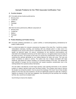
77 Taras Avenue P.O. Box 363 Altona North, Vic 3025 Australia Phone: +61(0)3 9369 1234 Fax: +61(0)3 9369 3456 E-mail: [email protected] Web: www.daviescraig.com.au Part No. 698 - HYDRA-COOL TRANSMISSION OIL COOLER DCSL 8” THERMATIC FAN COMBO KIT PLEASE READ THESE INSTRUCTIONS VERY CAREFULLY BEFORE BEGINNING INSTALLATION. FAILURE TO COMPLY MAY VOID YOUR WARRANTY. INTRODUCTION Congratulations on the purchase of your new 21-plate Transmission Oil Cooler and DCSL 8” Thermatic Fan Combo Kit. Your Combo kit is designed to cool transmission oil at all times but especially during sustained high speed driving, stop / start / traffic, towing heavy loads, 4WD off-road / climbing conditions. Your Transmission Oil Cooler Combo Kit will guard against the transmission oil overheating and assist in related operating conditions where transmissions are subjected to stress. Your Transmission Oil Cooler Combo Kit (Fig.1) contains the following components for quick and simple installation; No. Part No. Part Description Quantity 1 0814 Hose 3/8” 1.4 m 2 0853 Cooler Core 1 3 0135 DCSL 8” Fan 1 4 0571 Hardware bag 1 5 0532 Wiring Loom 1 6 210 Quick Fit Kit 1 Figure 1 GENERAL 1. The Hydra-Cool Transmission Oil Cooler Combo Pack is easy to install, however these “Installation Instructions” should be studied and clearly understood prior to starting your installation. 2. The fitment of the DCSL 8” Thermatic Fan with the Oil Cooler offers greater mounting flexibility as the fan will pass air through the core while in operation. The Transmission Oil Cooler relies on air-flow to provide maximum cooling efficiency. The ideal location in the vehicle is where the oil cooler will receive maximum air-flow, either from vehicle motion or from the active fan. Your Transmission Oil Cooler & Fan Combo Kit gives you greater flexibility when examining your mounting options. Either vertical or horizontal positions can be deployed. NOTE: The Hydra Cool Transmission Oil Cooler will protect your transmission oil from overheating, but it cannot correct a faulty transmission. The vehicle’s mechanical condition should be checked by a competent mechanic prior to installation if faults are suspected. P/No 0961 TYPES OF INSTALLATION (FIGURE 2) IN-SERIES - The recommended Transmission Oil Cooler connection is the “in-series” installation. It utilises the existing transmission cooling system and complies with all new car warranties. This method coupled with the DCSL 8” fan provides maximum cooling effectiveness by returning the coolest oil directly to the transmission. REPLACEMENT - This method can be used if the existing cooling system is severely damaged and beyond repair. The installation of this Cooler and DCSL 8” Fan Combo may provide equivalent total cooling if the DCSL 8” Thermatic fan is fully active during the vehicle operation. IN-SERIES INSTALLATION REPLACEMENT INSTALLATION OIL COOLER & FAN ASSEMBLY OIL COOLER &FAN ASSEMBLY FIGURE 2 TRANSMISSION OIL LINE IDENTIFICATION Most vehicles have the Transmission Cooler built-in to the side (or bottom) tank of the radiator. The additional cooler must be mounted downstream of this to minimise oil temperatures. Method 1 – Check oil line temperature (1 & 2) in Fig. 3. 1. Start engine whilst engine is cold 2. With park & foot brake engaged, place transmission shift lever in drive for no more than 10 seconds 3. Stop engine & remove keys 4. Identify oil return line by feeling both oil lines (1 & 2). Coolest line is the oil return line. Method 2 – (Requires an observer) – Check Oil Flow Direction 1. Place container under Transmission Oil Line (2) and disconnect oil line at radiator. Caution – use backup spanner to avoid damage to radiator fitting. 2. Have observer ready to watch radiator fitting. With park & foot brake engaged, start engine & place transmission shift lever in drive position. (2) (1) FIGURE 3 3. Stop engine immediately 4. Identify direction of oil flow. Oil must be pumped from radiator side for proper “in-series” connection. If oil flowed from radiator then that line must be connected to the new cooler. If oil did not flow from radiator then that hose must be refitted and the other line connected to the new cooler. 5. Reconnect oil hose line to radiator. Follow steps 1-16 on page 4 or A1-A5 on page 6. Page 2 of 8 INSTALLATION GUIDELINES 1. Keep rubber hoses away from sharp edges, moving parts, points of wear or points of heat such as exhaust pipes, manifolds, etc. Secure hoses with nylon tie straps. 2. Do not kink hose or bend it tightly. A bend of less than 75mm radius will put excessive stress on the hose and void warranty. 3. Cooler-Fan Assembly should be mounted at least 25mm from other fans, 50mm from hood, wheel wells and fire-wall, and 150mm from exhaust manifolds. When mounting to A/C condenser or radiator, foam pads must be used between the cooler and condenser/radiator. 4. Do not over-tighten hose clamps. Tighten only until rubber protrudes level with slots in hose clamp. If rubber protrudes through the slots, warranty will be void. 5. After 2 weeks, retighten hose clamps to insure against leakage. Tools Required For Most Installations • Screwdriver or nut runner to attach hose clamps and brackets. • Shifting spanner (or open end spanner) to remove & replace line fittings and bolts. • Tube cutter and flare tool to prepare tubes. • Knife to cut hose and plastic. TRANSMISSION OIL COOLER CORE & THERMATIC FAN ~ MOUNTING POSITIONS Note: The DCSL 8” Thermatic Fan supplied with this combo pack is reversible and may be mounted as an upstream (pusher) or downstream (puller) on the core. Your DCSL 8” Thermatic Fan has been factoryassembled to be mounted upstream. For downstream operation, remove the hex nut which secures the blade, remove the blade from the motor shaft, turn blade over and replace the hex nut. In every case follow the instructions printed on the blade hub. The Transmission Oil Cooler and Fan Combo Kit can be mounted in a convenient position either horizontally or vertically in the engine compartment (Ref. Figure 4) or a suitable location away from the engine compartment. In both cases, it’s important the fan is able to push/pull as cool air as possible for effective operation. Try to avoid mounting this unit too close to the engine, transmission or radiator. (2) (1) Locations 1 & 2 shows the possible places to mount the Cooler-Fan combo in the engine compartment FIGURE 4 Double check all hose clamps to ensure they are secure and they are do not contact the exhaust system, other hot components or interface with any moving parts. To ensure efficient circulation, the angle of the hoses is not less than 75mm (3”) radius. Figure 4 shows the possible location in the engine compartment PREPARATIONS TO MOUNT THE 8” THERMATIC FAN TO THE COOLER CORE Your DCSL 8” Thermatic Fan will mount on only one side of your 21-plate core and therefore it is important you choose how you wish the fan to operate. Determine whether your Thermatic Fan is to be set up as a ‘pusher/upstream’ or ‘puller/downstream’. Pay particular attention to the markings on the fan blade hub regarding the direction the fan faces. These instructions must be followed, whether you plan to mount the fan operating in an upstream or downstream mode. The fan must rotate in the direction of the arrow on the hub. Please note the direction of the rotation arrow on the blade hub before the fan is installed. The arrow may not be visible after installation. 1. Position the fan unit directly on the face of the core; rotate the fan blade manually to ensure the blade is not touching with the core. Check that the fan motor wire exit is facing downwards in the final assembly (i.e. at 6 o’clock), so that any condensation formed in the motor can drain. 2. Using the mounting hardware supplied, secure the fan to the face of the core (Refer figure 5). Taking note to ensure you have allowed for the fan’s air flow direction and final mounting position. Page 3 of 8 2.1 Screw on fan and firmly secure the lock nuts. Determine where you wish to mount your Transmission Oil Cooler. Then determine the lengths of the two hoses required, ensuring there are no tight turns or kinks in each hose. Cut hose to suit. 3 Place clamp on to the end of 3/8” hose provided and push each hose on to both cooler fittings. 4 Position clamps 6mm from end of hose and tighten clamps until rubber protrudes level with clamp slots 5 Place clamp on to the other end of these hoses. 6 Position the clamps and tighten it. Do not over- tighten clamps 7 Follow the steps of hose and clamp assembly instructions shown below Fan secured to the Core using the mounting hardware supplied (4 places) FIGURE 5 Motor wire exit downwards HOSE & CLAMP ASSEMBLY INSTRUCTIONS (VEHICLES WITH RUBBER HOSE CONNECTION TO EXISTING TRANSMISSION LINES) HOSE INSTALLATION MAY BE USED ON VEHICLES WITH 5/16” & 3/8” STEEL LINES 1. Place hose clamps over the ends of each hose and push hose onto oil cooler fittings. Leave hose in a loop – DO NOT CUT HOSE! 2. Position hose clamps 6mm from end of hose then tighten until rubber protrudes level with clamp slots. Do NOT over-tighten hose clamps. 3. If mounting oil cooler behind radiator (position 2, figure 4), allow minimum of 25mm clearance between rear face of cooler fan combo and engine driven fan blade. 4. Remove adhesive backing from foam pads. Position pads on cooler mounting flange. Press pads to ensure the adhesive sticks to the cooler. 5. Place and hold oil cooler combo in desired mounting location with pads facing radiator or air conditioning condenser (Fig. 6) Insert rod through cooler at mounting location where pad is positioned, then through the radiator and/or condenser. 6. Install locking button. These are permanent and can only be removed by cutting. Tighten to compress foam pad. Cut off excess mounting rods. 7. Repeat steps 5 through 7 for remaining ties. Procedures to complete the cooler installation 8. Cut hose to easily reach (no kinks) downstream oil pipe on radiator or transmission (refer fig 2). 9. Fit hose clamp over end of hose and slide hose onto radiator pipe or transmission about 30mm. (refer fig 2) 10. Position clamp 6mm from end of pipe and tighten until rubber protrudes FIGURE 6 Page 4 of 8 level with the clamp slots. DO NOT OVER TIGHTEN. 11. Cut downstream hose from Cooler so that it easily reaches the return line from the transmission. Remove the old hose from the return line and fit new hose from the cooler with clamp 6mm from end of pipe. DO NOT OVERTIGHTEN CLAMP. 12. CHECK THAT NEW HOSES ARE NOT KINKED, FOULING ANY MOVING OBJECTS OR NEAR ANY SHARP EDGES 13. Start engine. Place shift lever at position as stated in Vehicle Owners Manual for checking transmission oil levels. 14. Operate engine at fast idle for 2 minutes. Check hose connections for leakage. If leakage is found, stop engine and tighten clamps. 15. Feel both lines to cooler to be sure they are warm. If both are not warm, oil is not flowing through cooler. Check for kinked lines or other obstructions to flow. 16. Check Transmission Oil level. Stop engine and add oil if required. CAUTION: Do not overfill transmission. Only use transmission fluid recommended by the motor vehicle manufacturer. FAN WIRING INSTRUCTIONS WARNING: Do not use the vehicle’s engine management system or wiring connected to the engine management system as an ignition source as this may cause failure of the management system and/or electrical system. The ignition source must be a steady 12v DC supply. IMPORTANT: Do not secure your Thermatic Fan’s wiring until you have checked and confirmed the direction of rotation of the fan blades. 17. Temporarily connect the leads from the motor to the black and blue leads of the harness supplied / ignition source. Please refer to the Fan wiring diagram below. (refer fig 7) 18. If the Fan turns in the direction of the arrow on the Fan blade, make the motor connections permanent. If not, swap the motor connections and make them permanent 19. To confirm air flow direction, place a piece of paper (or similar) against the fan shroud. Air must flow freely through the core from the grill to the engine. 20. Ensure that all electrical connections are permanent and properly insulated, and that all wiring is fitted to avoid sharp edges and contact with hot parts of the engine. 21. Test drive vehicle. Hose connections should be periodically checked for leakage, and re-tightened if necessary. Fan wiring diagram Figure 7 1. 2. 3. 4. 5. 6. Blue Connector Self Tapper Scotch lock Ring Terminal Fuse Relay Page 5 of 8 HOSE INSTALLATION ~ WHERE TRANSMISSION OIL LINES ARE METAL. (ALTERNATIVE METHOD) Follow installation guidelines on page 3, and hose clamp assembly steps 1 through 7, on page 4. A1. Place container under oil return line and carefully cut line 100 mm from radiator or transmission. (refer fig 2) A2. Carefully remove sharp edges and burrs from ends of cut oil line. Flare both ends of the oil line to prevent loss of fluid under pressure. A3. Position hose loop next to flared ends of oil line and cut hose to length. Slide hose clamps loosely onto both ends and push hoses onto each of the flared oil lines about 30mm. A4. Position clamps 6mm behind flare in oil lines and tighten. Overtightening may void warranty. Tighten only until rubber protrudes level with the slots in the clamp. REAR OIL A5. Perform steps 11 through 16, page 5. FIGURE 8 ADDITIONAL TOOLS NECESSARY FOR APPLICATIONS USING ALTERNATE METHOD: (NOT SUPPLIED) Flaring tool or drift punch (to flare ends of transmission oil line) Small round file or emery cloth (to remove sharp edges or burrs) Steel tube cutter or hacksaw (to cut selected transmission oil line) If you are in doubt about any aspect of these instructions, please consult your retailer or Davies, Craig P/L direct on (03) 93691234 or email: [email protected] Also frequently asked questions about our products are available on our website www.daviescraig.com.au Page 6 of 8 WARRANTY We warrant that for a period of two years, 40,000km or 2000 hours continuous running (whichever is the lesser) from the date of purchase, we shall carry out, free of cost, any repairs that are reasonably necessary to correct any fault in the operation of your Davies Craig product provided that such a fault is directly attributable to a defect in the workmanship or materials used in the manufacture of the part(s) and is not due to installation other than described in these instructions. Labour and consequential costs are excluded. The benefits covered by this warranty extend to all the components in this kit and are in addition to all other rights and remedies in respect of the kit which the consumer has under the Trade Practices Act and similar State and Territory laws DAVIES, CRAIG PTY. LTD. REGISTER YOUR WARRANTY AT: http://www.daviescraig.com.au/Warranty-content.aspx SHOP ONLINE AT: www.daviescraig.com.au Page 7 of 8 Page 8 of 8


© Copyright 2026