
Household appliances Engineering Studies Preliminary Course Stage 6
Engineering Studies
Preliminary Course
Stage 6
Household appliances
ES/S6 – Prelim 41080
P0020451
Acknowledgments
This publication is copyright Learning Materials Production, Open Training and Education Network –
Distance Education, NSW Department of Education and Training, however it may contain material from
other sources which is not owned by Learning Materials Production. Learning Materials Production
would like to acknowledge the following people and organisations whose material has been used.
Board of Studies, NSW
All reasonable efforts have been made to obtain copyright permissions. All claims will be settled in
good faith.
Matrials development: John Burns
Revised version:
Brian Jobson, Jeff Appleby, Joesphine Wilms and Stephen Russell
Coordination:
Jeff Appleby and Nicola Pegum
Illustrations:
Tom Brown and David Evans
DTP:
Nick Loutkovsky and Carolina Barbieri
Copyright in this material is reserved to the Crown in the right of the State of New South Wales.
Reproduction or transmittal in whole, or in part, other than in accordance with provisions of the
Copyright Act, is prohibited without the written authority of Learning Materials Production.
© Learning Materials Production, Open Training and Education Network – Distance Education,
NSW Department of Education and Training, 1999. 51 Wentworth Rd. Strathfield NSW 2135.
Revised 2001
Module contents
Subject overview ................................................................................ iii
Module overview................................................................................ vii
Module components ................................................................ viii
Module outcomes ...................................................................... ix
Indicative time ............................................................................x
Resource requirements...............................................................x
Icons ..................................................................................................... xi
Glossary............................................................................................. xiii
Directive terms.................................................................................. xix
Part 1: Household appliances – development......................... 1–33
Part 2: Household appliances – materials .............................. 1–41
Part 3: Household appliances – mechanics ............................ 1–41
Part 4: Household appliances – electricity and
communication ................................................................ 1–63
Part 5: Household appliances – Engineering report............... 1–20
Bibliography........................................................................................21
Module evaluation .............................................................................23
i
ii
Subject overview
Stage 6 Engineering Studies Preliminary Course and HSC Course each
have five modules.
Engineering Studies Preliminary Course
Household appliances examines common appliances
found in the home. Simple appliances are analysed
to identify materials and their applications.
Electrical principles, researching methods and
techniques to communicate technical information are
introduced. The first student engineering report is
completed undertaking an investigation of materials
used in a household appliance.
Landscape products investigates engineering
principles by focusing on common products, such as
lawnmowers and clothes hoists. The historical
development of these types of products demonstrates
the effect materials development and technological
advancements have on the design of products.
Engineering techniques of force analysis are
described. Orthogonal drawing methods are
explained. An engineering report is completed that
analyses lawnmower components.
Braking systems uses braking components and
systems to describe engineering principles. The
historical changes in materials and design are
investigated. The relationship between internal
structure of iron and steel and the resulting
engineering properties of those materials is detailed.
Hydraulic principles are described and examples
provided in braking systems. Orthogonal drawing
techniques are further developed. An engineering
report is completed that requires an analysis of a
braking system component.
iii
Bio-engineering examines both engineering
principles and also the scope of the bio-engineering
profession. Careers and current issues in this field
are explored. Engineers as managers and ethical
issues confronted by the bio engineer are considered.
An engineering report is completed that investigates
a current bio- engineered product and describes the
related issues that the bio-engineer would need to
consider before, during and after this product
development.
Irrigation systems is the elective topic for the
preliminary modules. The historical development of
irrigation systems is described and the impact of
these systems on society discussed. Hydraulic
analysis of irrigation systems is explained. The
effect on irrigation product range that has occurred
with the introduction of is detailed. An engineering
report on an irrigation system is completed.
iv
HSC Engineering Studies modules
Civil structures examines engineering principles as
they relate to civil structures, such as bridges and
buildings. The historical influences of engineering,
the impact of engineering innovation, and
environmental implications are discussed with
reference to bridges. Mechanical analysis of bridges
is used to introduce concepts of truss analysis and
stress/strain. Material properties and application are
explained with reference to a variety of civil
structures. Technical communication skills
described in this module include assembly drawing.
The engineering report requires a comparison of two
engineering solutions to solve the same engineering
situation.
Personal and public transport uses bicycles, motor
vehicles and trains as examples to explain
engineering concepts. The historical development of
cars is used to demonstrate the developing material
list available for the engineer. The impact on
society of these developments is discussed. The
mechanical analysis of mechanisms involves the
effect of friction. Energy and power relationships are
explained. Methods of testing materials, and
modifying material properties are examined. A
series of industrial manufacturing processes is
described. Electrical concepts, such as power
distribution, are detailed are introduced. The use of
freehand technical sketches.
Lifting devices investigates the social impact that
devices raging from complex cranes to simple car
jacks, have had on our society. The mechanical
concepts are explained, including the hydraulic
concepts often used in lifting apparatus. The
industrial processes used to form metals and the
methods used to control physical properties are
explained. Electrical requirements for many devices
are detailed. The technical rules for sectioned
orthogonal drawings are demonstrated. The
engineering report is based on a comparison of two
lifting devices.
v
Aeronautical engineering explores the scope of the
aeronautical engineering profession. Career
opportunities are considered, as well as ethical
issues related to the profession. Technologies unique
to this engineering field are described. Mechanical
analysis includes aeronautical flight principles and
fluid mechanics. Materials and material processes
concentrate on their application to aeronautics.
The corrosion process is explained and preventative
techniques listed. Communicating technical
information using both freehand and computer-aided
drawing is required. The engineering report is based
on the aeronautical profession, current projects and
issues.
Telecommunications engineering examines the
history and impact on society of this field. Ethical
issues and current technologies are described.
The materials section concentrates on specialised
testing, copper and its alloys, semiconductors and
fibre optics. Electronic systems such as analogue
and digital are explained and an overview of a
variety of other technologies in this field is
presented. Analysis, related to telecommunication
products, is used to reinforce mechanical concepts.
Communicating technical information using both
freehand and computer-aided drawing is required.
The engineering report is based on the
telecommunication profession, current projects and
issues.
Figure 0.1 Modules
vi
Module overview
In Part 1 you will begin to investigate the historical developments of
household appliances. Some useful terms will be introduced. You will
explore the development of floor cleaners, electric irons and
refrigerators.
To help you understand the importance of material selection for
household appliances you will learn about the methods of classifying
materials. The atomic structure and bonding of materials will be
analysed. Lastly you will learn about research methods to prepare you
for writing an engineering report at the end of the module.
You will build on your knowledge of materials and components by
studying about the use of metals. Types of metals, such as ferrous and
non-ferrous, will be explained.
You will then learn about cutting and joining currently used in household
appliances. Polymer materials and ceramic materials and their uses are
explored. Additional researching techniques are introduced, which you
will need to help you eventually complete your Engineering Report.
In part 3 you will develop a basic understanding of engineering
mechanical principles.
Concepts such as mass and force are defined. Next scalar and vector
quantities are classified and a method of determining components of a
force is explained.
In Part 4 of this module you will study basic forms of
electricity/electronics for household appliances. Principles such as
potential difference, current, and components are described.
You will learn how to identify principles of electrical safety and learn
about induction. Freehand orthogonal drawing concepts are detailed.
By part 5 you have practiced and completed your research methods and
will know most of the steps for writing your engineering report.
vii
It will be time to pull all those skills together and collate your
information into one report. You will need to research and study one
household appliance. You will develop your report using your writing
skills to communicate information and drawing skills to illustrate your
work.
Module components
Each module contains three components, the preliminary pages, the
teaching/learning section and additional resources.
•
The preliminary pages include:
–
module contents
–
subject overview
–
module overview
–
icons
–
glossary
–
directive terms.
Figure 0.2 Preliminary pages
•
Figure 0.3 Teaching/learning section
viii
The teaching/learning parts may
include:
–
part contents
–
introduction
–
teaching/learning text and tasks
–
exercises
–
check list.
•
The additional information may
include:
–
module appendix
–
bibliography
–
module evaluation.
Additional
resources
Figure 0.4 Additional materials
Support materials such as audiotapes, video cassettes and computer disks
will sometimes accompany a module.
Module outcomes
At the end of this module, you should be working towards being able to:
•
describe the types of materials, components and processes used to
make household appliances and explain any implications for
engineering development (P1.2)
•
explain the relationship between properties, uses and applications of
materials in engineering (P2.1)
•
develop written, oral and presentation skills and apply these to
engineering reports (P3.2)
•
applied graphics as a communication tool (P3.3)
•
describe the developments in technology and their impact on
engineering products (P4.1)
describe the influence of technological change on engineering and its
effect on people (P4.2)
•
•
identify the social, environmental and cultural implications of
technological change in engineering (P4.3).
Extract from Stage 6 Engineering Studies Syllabus, © Board of Studies, NSW, 1999.
Refer to <http://www.boardofstudies.nsw.edu.au> for original and current documents.
ix
Indicative time
The Preliminary course is 120 hours (indicative time) and the HSC
course is 120 hours (indicative time).
The following table shows the approximate amount of time you should
spend on this module.
Preliminary modules
Percentage of time
Number of hours
Household appliances
20%
24 hr
Landscape products
20%
24 hr
Braking systems
20%
24 hr
Bio-engineering
20%
24 hr
Elective: Irrigation systems
20%
24 hr
HSC modules
Percentage of time
Number of hours
Civil structures
20%
24 hr
Personal and public transport
20%
24 hr
Lifting devices
20%
24 hr
Aeronautical engineering
20%
24 hr
Telecommunications engineering
20%
24 hr
There are five parts in Household appliances. Each part will require
about four to five hours of work. You should aim to complete the
module within 20 to 25 hours.
Resource requirements
During this module you will need to access a range of resources including:
•
access to an early and late model household appliance
•
technical drawing equipment such as
-
rule, pencils, eraser and compasses
-
protractor and set squares.
For research you are encouraged to use the Internet, CD Roms and books
through your local, school or TAFE library.
x
Icons
As you work through this module you will see symbols known as icons.
The purpose of these icons is to gain your attention and to indicate
particular types of tasks you need to complete in this module.
The list below shows the icons and outlines the types of tasks for Stage 6
Engineering studies.
Computer
This icon indicates tasks such as researching using an
electronic database or calculating using a spreadsheet.
Danger
This icon indicates tasks which may present a danger and
to proceed with care.
Discuss
This icon indicates tasks such as discussing a point or
debating an issue.
Examine
This icon indicates tasks such as reading an article or
watching a video.
Hands on
This icon indicates tasks such as collecting data or
conducting experiments.
Respond
This icon indicates the need to write a response or draw
an object.
Think
This icon indicates tasks such as reflecting on your
experience or picturing yourself in a situation.
xi
Return
This icon indicates exercises for you to return to your
teacher when you have completed the part. (OTEN OLP
students will need to refer to their Learner's Guide for
instructions on which exercises to return).
xii
Glossary
As you work through the module you will encounter a range of terms that
have specific meanings.
The list below explains the terms you will encounter in this module.
These terms are bolded the first time they occur in the text.
alternating current
when electrons flow (electric current) first in one
direction and then flows back again and continue
this back and forth motion
atom
a component of all matter
body-centred cubic
A type of crystal structure
abbreviated to BCC
box up
divide a shape into sections/areas/cubes so that it
is broken down into easier to draw segments
brush
A connector used to maintain electric contact
between stationary and moving parts in a motor.
ceramics materials
are versatile engineering materials, including
such common items as brick, porcelain, glass,
and cement
commutator
a device for reversing the direction of an electric
current in a motor
dichlorodifluoromethane a ‘non toxic’ substitute for ammonium as a
coolant, now banned, abbreviated to CFC-12
coefficient of expansion
a measurement that describes the change in size
of material relative to the temperature
compressive force
describes a force applied to an object that
attempts to compress the object
conventions
agreed upon rules or practices
crystalline material
the atoms form into definite repeating patterns or
‘lattice’ structures
density
a measurement of a materials mass per unit
volume
xiii
xiv
direct current
when electrons flow (electric current) in one
direction along the conductor
direction
a measurement of the angle (normally measured
off the horizontal) measured in degrees
drawing into wire
pulling metal through a die to form a wire
ductile
able to be stretched without failure
elasticity
the property of a material to return its original
shape after a distorting force has been removed
electrical current
the movements of electrons along the conductor
in a particular direction which produces an
electric current
electrical conductivity
the ability of a material to conduct electricity
electrons
orbit the nucleus in layers (shells) and are
negative in charge
electro-chemical bonds
hold the atoms more rigidly together
electromagnet
a magnet made by passing electrical current
through a coiled conductor wrapped around a
ferrous core
element
passing an electric current through a wire,
thereby creating heat
elements
materials composed of only one type of atom
equilibrant
an equal force acting as a balance to maintain, or
bring about, a state of equilibrium
ergonomics
designing for bodily needs of a given working
environment
face-centred cubic
A tpe of crystal structure
abbreviated to FCC
ferrous metals
metals which contain primarily iron with small
proportions of other materials
force
the interaction between bodies
force component
a component of a vector is the effect of that
vector in a specific direction. The components
of a vector add to equal the original vector
formability
a material’s ability to be deformed or shaped by
bending, stretching, compressing
freon
a coolant used in the refrigeration process – is
damaging to the ozone layer
frictional properties
the property of a material that describes the
amount of grip a material has when sliding in
contact with another surface
fusible
able to be joined together
hardness
the property of a material to resist penetration or
scratching when brought into contact with
another material
hexagonal close packed
A type of crystal structure
abbreviated to HCP
lattice
created when the atoms form into definite
repeating patterns
magnetic flux density
magnetic field strength; a magnetic field is
represented by lines of ‘flux’ – the denser the
field or lines of flux, or the closer the lines are,
the stronger the magnetic filed
magnetic properties
the ability of a material to become magnetic
magnetic induction
a process enabling the spin axes of electrons to
be aligned thus creating a magnet
magnitude
the size or how much of something
mass
the amount of matter that is contained within that
object
melting point
the temperature at which the material begins to
become a liquid
neutrons
are located in the nucleus, have no electrical
charge and are a similar size to the protons
newton
is a unit of force represented by the symbol N
nichrome
a metal alloy of nickel and chromium
non ferrous metals
metals which contain little or no iron
non-oxidising
does not form an oxide, chemically stable
nucleus
lies at the centre of the atom, consisting of
protons and neutrons
opacity
the property of a material that stops the passage
of light, that is, you cannot see through it
orthogonal
drawing where an object is fully described by
projecting a series of related views from various
viewing positions (above, front on, side on)
xv
xvi
porcelain
a ceramic product that is stable, smooth and is an
insulator
primary bonds
the main bonds holding material together
protons
are located in the nucleus, are positive in charge
and are equal in number to the electrons orbiting
the nucleus
prototype
an initial version of an item, often produced at
the development stage of a product
radiated heat
heat that is transmitted through the air
relative density
a measurement for material describing how
compact the mass of the object is relative to
other materials
resistance to corrosion
describes the property of a material that allows it
to not corrode quickly in a service application
resistance to creep
the property of a material to maintain its original
length for a long period of time when a small
load is applied
resultant force
describes effects when a system of two or more
forces is analysed
rotor
Rotating coil used in simple electric motors
scalar quantity
is a quantity that requires only magnitude (size)
for its complete understanding
secondary bonds
weak bonds normally caused by attraction
between positive and negative parts of molecules
that are close to one another
stability
describes how a material reacts to external
changes
stator
Are the stationary magnets used in an electric
motor
Steel
an alloy of iron and carbon
stiffness
the property of a material to maintain shape
strength
the property of a material to withstand forces.
Normally strength is specified as yield strength,
tensile strength, compressive strength, shear
strength
tensile force
describes a force applied to an object that
attempts to stretch the object
thermal conductivity
the property of a material to conduct heat
thermopolymer
polymers which, once set, can be melted and
re-formed
thermosetting
polymers which, once set, cannot be remelted or
reshaped
tonne
a tonne, represented by the symbol T, is equal to
1000 kg
tough
able to have force applied without failure
toxicity
describes how harmful a material is to the
environment
Uniform Resource
Locater
address of an Internet site abbreviated to URL
vector
quantity that has magnitude and direction/sense
vector quantity
a quantity that requires direction as well as
magnitude for its complete understanding
xvii
xviii
Directive terms
The list below explains key words you will encounter in assessment tasks
and examination questions.
account
account for: state reasons for, report on;
give an account of: narrate a series of events or
transactions
analyse
identify components and the relationship between
them, draw out and relate implications
apply
use, utilise, employ in a particular situation
appreciate
make a judgement about the value of
assess
make a judgement of value, quality, outcomes,
results or size
calculate
ascertain/determine from given facts, figures or
information
clarify
make clear or plain
classify
arrange or include in classes/categories
compare
show how things are similar or different
construct
make, build, put together items or arguments
contrast
show how things are different or opposite
critically
(analyse/evaluate)
add a degree or level of accuracy depth, knowledge
and understanding, logic, questioning, reflection
and quality to (analysis/evaluation)
deduce
draw conclusions
define
state meaning and identify essential qualities
demonstrate
show by example
xix
describe
provide characteristics and features
discuss
identify issues and provide points for and/or against
distinguish
recognise or note/indicate as being distinct or
different from; to note differences between
evaluate
make a judgement based on criteria; determine the
value of
examine
inquire into
explain
relate cause and effect; make the relationships
between things evident; provide why and/or how
extract
choose relevant and/or appropriate details
extrapolate
infer from what is known
identify
recognise and name
interpret
draw meaning from
investigate
plan, inquire into and draw conclusions about
justify
support an argument or conclusion
outline
sketch in general terms; indicate the main
features of
predict
suggest what may happen based on available
information
propose
put forward (for example a point of view, idea,
argument, suggestion) for consideration or action
recall
present remembered ideas, facts or experiences
recommend
provide reasons in favour
recount
retell a series of events
summarise
express, concisely, the relevant details
synthesise
putting together various elements to make a whole
Extract from The New Higher School Certificate Assessment Support Document,
© Board of Studies, NSW, 1999.
Refer to <http://www.boardofstudies.nsw.edu.au> for original and current documents.
xx
Household appliances
Part 1: Household appliances – development
Part 1 contents
Introduction............................................................................................ 2
What will you learn?.................................................................... 2
Overview of early technology............................................................ 3
Household appliances ........................................................................ 6
Common household appliances ................................................. 7
Developing your research skills........................................................ 25
Exercises............................................................................................ 27
Progress check................................................................................... 31
Exercise cover sheet......................................................................... 33
Part 1: Development of household appliances
1
Introduction
In this part of the module you will examine the development of different
household appliances through case studies.
Looking at developments in household appliances allows you to gain an
appreciation for engineering innovation through past achievements and
focus on the connection between the needs of society and the engineering
field which drives the development of new and better products.
When researching developments you will need to find out about early
forms of technology, the societal effects of the scientific and industrial
revolution and the effect on engineering development.
As you are reading keep in mind how developments in household
appliances affect different groups of people in society. For example, ask
yourself would a 19th century copper kettle be safe for people to use, such
as an older person with arthritis, a child under twelve, a slightly built
person, easy to produce, affordable to buy and economical to repair?
Keep these issues in mind in your study of the developments of
household appliances.
You will need to write an engineering report in the last part of this
module. This will require research into the material used in a household
appliance.
What will you learn?
You will learn about:
•
the historical and societal influences by studying;
–
the historical developments of household appliances
–
the effects of engineering innovation on people’s lives.
You will learn to:
•
outline the historical development of household appliances
•
describe the effect of engineering innovation on people’s lives.
Extract from Stage 6 Engineering Studies Syllabus, © Board of Studies, NSW, 1999.
Refer to <http//www.boardofstudies.nsw.edu.au> for original and current documents.
2
Household appliances
Overview of early technology
The development of engineering principles and techniques can be closely
linked to the general development of societies. Engineering has been a
central force in all economic and social growth. In this part of the module
you will examine several engineering developments and consider some
effects they had on society.
Before you begin …
What would you consider is the most important mechanical invention of
all time?
Our choice will be revealed later!
It is not necessary to study ancient civilisations in order to gain some
understanding of the effect of engineering. However, you could research
the effect the development of tools had on ‘stone age’ society. You could
research the developments of agricultural implements and the agrarian
revolution. You could research the earliest use of metals (and their
smelting) and the dramatic effect they had on societies during the bronze
and iron ages.
There is also a history of engineering and science principles. These are
revealed in the groundbreaking books and manuscripts of Aristotle (Greek
civilisation) Michelangelo, Leonardo da Vinci and Machiavelli
(renaissance period in Italy). This list could continue to fill a book!
Technological advancement has tended to ebb and flow over the many
centuries. There have been periods of development followed by periods
of little change. This pattern ended by about 1750, the start of the
‘Industrial Revolution’. The period from 1750 to the 1900s saw change
like the world had never seen previously. This revolution in technology
has only been surpassed by the technology revolution you are living with
today.
The following list provides a few examples of the many thousands of
engineering developments during this period.
Part 1: Development of household appliances
3
Try to think of one additional invention or development for each of the
following areas:
•
•
•
•
•
4
materials
–
developments in the iron making industry
–
automation of textile manufacture
–
development of coal as an industrial energy source
–
development of building materials such as bricks and reinforced
concrete
–
mass production of glass
transport
–
invention of the steam engine
–
development of a railway system
–
expansion of the canal systems
–
development of the steam turbine (ship propulsion)
–
development of the internal combustion engine
–
development of the automobile
–
development of the air ship
tool making
–
development of accurate clocks for navigation
–
development of accurate distance/size measuring devices
–
development of accurate cutting devices for machine
manufacture
chemical knowledge
–
artificial fertiliser
–
explosives
–
dyes and inks
–
medicines (iodine, anaesthetics, carbolic acid)
–
voltaic battery
communication knowledge
–
printing press
–
telegraph
–
telephone
–
typewriter
–
photography/video
Household appliances
•
•
–
computer
–
satellite
electricity
–
electric lighting
–
electric motor
–
electric generator
food and agriculture
–
mechanised farm machinery
–
food processing plants
–
food preservation, packaging and refrigeration.
Back to the original question, which would you consider the most
important mechanical invention of all time? If you answered the ‘wheel’
then you agree with most people.
The invention of the wheel
The wheel appeared as early as 3 500 BC in Mesopotamia where
the first application was the potters’ wheel. This technology was
quickly adopted for transportation in the four-wheeled carts and
chariots.
You have now had a brief overview of some technology
developments. You will build on this information in the later
modules. You will now read about developments in household
appliances.
Part 1: Development of household appliances
5
Household appliances
When you look at household appliances and how they have developed
over the last century you will find it is an interesting way of identifying
technological and engineering change. Many current models only look
vaguely similar to the products first developed. When you consider the
models of today, you can see that many changes to the design have taken
place.
Some of the reasons for new developments include:
•
the development of new materials such as polymers
•
the invention of new power sources, for example, electricity and
solar power.
List two other factors that may have brought about new developments in
household appliances.
1
_______________________________________________________
2
_______________________________________________________
Did you answer?
The development of control devices and the new applications of existing
materials
Engineers, over time, have modified the household appliances to suit
today’s environment, modifying the external appearance, changing the
materials used, and addressing safety issues.
There are also less obvious changes and modifications to appliances to
make the product more attractive and profitable in the market place.
6
Household appliances
Common household appliances
A tour of the average home will reveal many household appliances.
The kitchen probably has more household appliances than any other
room in the home, you are likely to find a fridge, freezer, juicer, toaster,
non-stick pan, microwave oven, wall oven, cook top, coffee percolator,
even an electric knife.
1
Spend five minutes in the kitchen and list all the household
appliances specifically designed for food preparation.
_______________________________________________________
_______________________________________________________
_______________________________________________________
Did you answer?
Some of the kitchen appliances you may have found in the kitchen include
fridge, freezer, blender, juicer, toaster, electric fry pan, electric wok,
microwave oven, wall oven, cook top, coffee percolator, food processor,
electric knife, electric can opener, popcorn maker …
Many kitchen appliances were invented as labour saving items. They use
electric motors instead of manual labour to get jobs done. For example,
there are electric food processors for chopping, electric blenders to puree,
electric beaters to mix and electric brooms to sweep up the mess when
you are finished cooking.
In another part of a typical house you will find the entertainment area
complete with television, radio, cassette recorder, compact disc player,
some of which today are controlled remotely.
These labour saving devices were only possible after the discovery of
electricity and the invention of small electric motors. Most of them
weren't invented until after homes in North America and Europe were
‘electrified’, that is connected to a source of electricity, in the 20th
century.
Common household appliances include:
•
food mixer
•
floor cleaners
•
clothes iron
•
bread toaster
•
kettle
•
refrigerator.
Part 1: Development of household appliances
7
Before the introduction of electricity, many household appliances were
manually operated.
You will examine the developments of common household appliances
over time and the impact of engineering innovations on individuals.
Complete the following table:
a
describe the functional features of the early model household
appliances
b
identify a significant change in design to this product in the late model
equivalent.
Appliance
Early model
Late model
kettle
In the 1800s a kettle was
commonly made from iron.
The water was heated by a
wood fire. The product was
heavy and hot to touch
In the 1990s a kettle was
commonly made from
polymer. The water was
heated by an electric
element. The product is light
weight and cool to touch.
clothes iron
__________________________
_________________________
__________________________
_________________________
__________________________
_________________________
__________________________
_________________________
__________________________
_________________________
__________________________
_________________________
__________________________
_________________________
__________________________
_________________________
__________________________
_________________________
__________________________
_________________________
__________________________
_________________________
__________________________
_________________________
stove
Did you answer?
clothes iron
• made of cast iron
• made from aluminium and polymers
stove
• made from cast iron
• steel powered by gas and/or electricity
• source of heat wood
8
Household appliances
How did you go?
You would have found that today people use household appliances to
save time and energy.
You may also have noticed `these appliances have changed many times
in the last 50 years.
The food mixer
Many household appliances only vaguely resemble the products first
developed.
Examine figure 1.1 which shows an early model food mixer.
Figure 1.1
The early 1920s food mixer
Compare this early model food mixer to a late model food mixer by listing
three design differences.
1
_______________________________________________________
2
_______________________________________________________
3
_______________________________________________________
Did you answer?
• exposed motor housing and gearing
• revolving base plate/mixing bowl
• metal frame (insulated).
Part 1: Development of household appliances
9
When you consider the models of today, you can see that many changes
to the design have taken place.
Over time engineers have modified the food mixer by:
•
changing the external appearance to make it more appealing
•
using the latest materials
•
taking safety issues into account for example, reduced the noise level
•
using the latest manufacturing techniques to increase efficiency,
productivity and most importantly profitability.
Floor cleaners
This case study looks at the historical development of floor cleaning
appliances.
In this section you will examine the:
•
1858 carpet sweeper
•
1920s pump vacuum
•
1930s electric vacuum
•
2000 electric upright vacuum.
The floor sweeper
In 1858 H.H. Herrick designed the Brush sweeper.
Figure 1.2
10
Brush sweeper
Figure 1.3
Sectioned view of the brush sweeper
Household appliances
The functional features of this appliance included:
•
ability to clean carpets and smooth floor surfaces such as timber
•
the mechanism was contained within the strong, lightweight case
•
the brush consisted of helical rows of tufts
•
every second row of tufts were to suit flat timber floors whilst the
other rows of tufts were designed for carpeted surfaces.
•
the brush height was adjustable
•
the sweeper was pushed back and forth to turn the brushes. The
dust was collected in pans that could be opened and emptied
•
furniture was protected by a rubber guard that went round the outer
case.
The advantage of this type of floor cleaner was that it used no electricity,
which many households did not have at that stage.
The electric vacuum cleaner
Hubert Cecil Booth, an Englishman, designed and patented the first
practicable vacuum cleaner, but a number of patents for machines like this
had already been granted to other inventors.
Figure 1.4
Early electric vacuum cleaner
The problem for the early electric vacuum-cleaners was the motor.
Early electric motors were both large and heavy. This led to the
development of ducted vacuum cleaning systems that catered for many
Part 1: Development of household appliances
11
rooms, but only had one motor. Public buildings and blocks of flats were
suited to this ducted vacuum system which had the motor located in a
plant room or basement. This is similar to the ducted systems that some
homes have today.
Early in the twentieth century, Axel Wenner-Gren, was determined to
develop a vacuum cleaner that was low priced and light in weight for easy
handling. He developed a design that had a ‘closed fan’.
The fan is housed, and air is forced through a confined intake. This
development gave powerful suction from a small cleaner and is still a
component in current vacuum cleaner designs.
The upright vacuum cleaner
The electric upright type of vacuum cleaner was developed from the
earlier carpet sweeper.
The tuft brushes are now motor-driven and beater bars have been
developed and incorporated to move dust and dirt up enabling the
brushes to be more effective. A powerful fan forces the dust and dirt into
a disposable bag and the exhaust air is cleaned leaving the vacuum cleaner
by passing through a disposable filter.
Figure 1.5
Electric upright vacuum cleaner
The cylinder style vacuum
The cylinder style vacuum cleaner is designed with most components
such as the inlet tube, motor, fans and dust bag to be in-line. This style
of vacuum cleaner relies on suction alone and thus has neither revolving
brushes nor beater bars.
12
Household appliances
Figure 1.6
Sectioned view of a cylinder style vacuum cleaner
Recent developments
The vacuum cleaner shown below is the latest design. It has developed
into a light but powerful machine, and is also stylish and suitable for
mass production.
stick design
optional cord
see-through canister
specialist
attachments
power head
Figure 1.7
Late model vacuum cleaner
It is an important task to analyse the effect of any product and the effect
that product has on people’s lives. While the latest machine improves
the cleaning of the floors, and greatly decreases the time required to clean
the floors, there are other social and environmental effects.
The machine requires an initial outlay of household funds. It will require
maintenance. Use of the machine will add slightly to the electricity bill.
It will take up storage space. At the same time, the machine will allow a
carpet floor covering to be kept low in dust, and therefore much healthier
for the occupants of the house.
Part 1: Development of household appliances
13
The domestic clothes iron
Stones heated in the fire or in boiling water were the first tools used for
smoothing out wrinkles in clothes.
The flat iron
By 1850 there were two iron options available:
•
the flat iron – was made of iron and heated on a fire. Manufactured in
the eighteenth and nineteenth centuries.
•
the box iron – where a piece of preheated iron or a lump of coal was
placed in the box to keep the iron hot.
Flat irons, sometimes known as ‘sad irons’, were made from cast iron.
This made them very heavy and ironing became a time consuming chore
that required considerable muscular effort, both in the home and industrial
situation.
Figure 1.8
Early flat iron
Weight, cleanliness and the hot handle were the major concerns for the
user. The handle problem was partly overcome when a detachable
wooden handle was patented in 1865.
The weight of the hot iron was important as this helped with the
flattening of fabric. The iron was made in different shapes and sizes for
different purposes, such as pressing sleeves and hats.
Box irons provided an option to the flat iron where a hollow section was
incorporated into the design to receive either:
•
a piece of preheated iron
•
a lump of coal to keep the box iron hot.
This type of iron was an improvement on the flat iron heated in the
fireplace as it collected soot and had to be cleaned before use.
14
Household appliances
Bellows were used to blast air into the box and keep the coals hot. An
outlet was included to allow the smoke from the coals to escape from the
box.
Figure 1.9
Box iron and bellows
What effect do you think the escaping smoke could have on the ironing
environment?
__________________________________________________________
__________________________________________________________
Did you answer?
• the coal smoke would make the clothes smell after ironing
The self-heating irons
The next development in iron technology were self-heating irons. They
were fuelled with natural gas, gasoline, or alcohol that often exploded.
The electric iron was patented in 1882 but it didn't become popular until
electricity became available in homes.
Figure 1.10 Sectioned-view of a self heating iron
Part 1: Development of household appliances
15
The diagram above shows a very early electric iron that has been
sectioned to allow you to see the heating lamp. Heating elements were
developed later. Also note that timber was still used for the handle.
The electric irons
Early electric irons were similar to ‘sad irons’. As time went by
polymers were developed and instead of the wooden handles a material
called Bakelite was used.
Ironing was now starting to become faster and easier due to weight
reduction and manufacturers paying more attention to the style of the
products.
Westinghouse, a major manufacturer, designed a streamlined iron that
started a trend. The Bakelite handle was designed to fit a woman's hand.
Different temperature settings were available for various fabrics.
The steam iron
Sunbeam produced a steam iron called the Steam-0-Matic. The use of
steam, rather than the weight of the iron was the major factor in removing
wrinkles from the clothes.
Figure 1.11 Steam iron
© Goldman Ruben, S. 1998, Toilets, Toasters & Telephones, Hardcourt Brace &
company, Florida, p63
With emphasis on steam rather than weight, alterative materials were
used in the manufacture of irons. Aluminium rather than iron meant that
irons were becoming much lighter.
Recent developments
Today irons have been designed by engineers using the latest materials and
manufacturing processes, incorporate a range of features to ensure:
16
•
comfort
•
appearance
•
safety and ergonomics
Household appliances
Figure 1.12 A late model iron
© Koninklijke Phillips Electronics N.V.
1
2
From the previous diagram, list two the functional features of the
latest model iron.
i
___________________________________________________
ii
___________________________________________________
Explain the benefits of one of these functional features.
_______________________________________________________
_______________________________________________________
_______________________________________________________
3
List new materials and explain the advantages of the use of
these materials.
_______________________________________________________
_______________________________________________________
_______________________________________________________
4
List two safety features that are in the latest model of the iron.
i
___________________________________________________
ii
___________________________________________________
Part 1: Development of household appliances
17
Did you answer?
1 i
ii
temperature control
steam spray function
2 The temperature – can be change so as to not damage the materials to be
ironed.
3 Plastics have decreased the weight of the iron and because they do not
conduct heat well they are safe to use
4 i
ii
auto turn off – if the iron is accidentally left on it will turn itself off
plastic body ensures the operator is safe from electric shock
The refrigerator
Refrigeration is the process of lowering the temperature of a substance.
It is a common method of food preservation.
The time-line below gives you an overview of the main historical
developments of the refrigerator.
Notice how the materials and shape has changed through the years.
Figure 1.13 Evolution of the refrigerator
Early ice boxes
The icebox was the first household appliance used for refrigeration. The ice
manufacturing factory produced the ice and it was delivered to businesses and
houses by cart.
Early ice boxes used wood for the cabinet, sawdust for insulation and tin or
zinc as lining.
18
Household appliances
Figure 1.14 Early ice boxes
Early model refrigerators
The first refrigerated storage machines were developed during the early
1900s. The machines were very large, steam driven, manually operated
and sometimes leaked ammonia.
The first refrigerators and freezers driven by electricity were developed in the
1920s and the 1930s. It was not until the late 1940s that the first researchers
successfully scaled down the machines to a size suitable for shops.
Figure 1.15 Early 1920s model refrigerator
In the 1950s and 1960s a further development took place. Frost-free
refrigerators became available. These were more efficient and further
reduced the time required in household maintenance of the machine.
Part 1: Development of household appliances
19
Over time, research and development vastly improved the machines, but
by the 1960s it was evident that the Chloro Fluoro Carbons (CFCs) had a
harmful effect on the earth’s ozone layer and, therefore, the environment.
By the 1970s new refrigerants had been developed which were very
energy efficient. All CFCs were eliminated from the machines.
In 1992, researchers developed ‘Green freeze’, a hydrocarbon refrigerant.
This material is now becoming the coolant most commonly used.
Late model refrigerators
Late model refrigerators can come equipped with a computer within the
door. This computer has a large screen and key pad situated on the door
front that allows Internet ordering of food and other functions.
Figure 1.16 Computer refrigerator
The bread toaster
In the eighteenth-century English people made toast in their fireplaces
with a rack called the hanging griller. Another tool was the salamander, a
metal disk with a long handle or simply used long handled forks to toast
their bread.
Since the time of Thomas Edison, engineers have been using wire as an
element. When used for lighting, the wire is sealed in a vacuum or
surrounded by an inert gas. This prevents the element from oxidising or
burning. The toaster element had to perform the heating task in open air.
20
Household appliances
The basic principle for most toasters is cooking the bread by radiant heat.
The heat is created by passing an electric current through a wire, known
as an element.
In 1905 an engineer called Albert Marsh applied for a patent on an alloy
of Nickel and Chromium, which came to be known as Nichrome. The
alloy can be described as being:
•
very low in electrical conductivity
•
very fusible
•
non-oxidising to a very high degree
•
tough and sufficiently ductile to permit drawing into wire.
Consider that at this time electricity was not commonly wired into
houses. The common wall power outlet was still only a dream for the
future.
The electric flip sided toaster
General Electric, in 1909, made the first successful electric toaster called
‘D-12’. It was made from a wire rack and heating element attached to a
porcelain base that toasted one side of bread at a time.
There were variations of the early toasters, some were made with two
doors while others had slots or perforated, decorative designs.
Figure 1.17 Flip sided toaster
© LMP
One model from Universal had porcelain knobs that were cool to the
touch. Westinghouse developed the ‘Turnover Toaster’ which turned
the toast when you opened its doors.
Part 1: Development of household appliances
21
Some manufacturers produced a ‘Combo Toaster’ that cooked toast on
the table instead of on the stove. This could make coffee and toast at
the same time. Hotpoint developed the ‘El Grillo Perc-O-Toaster’
oven which could cook eggs and fry bacon.
Regulating time for cooking was a problem. People did not enjoy
eating burnt toast or burning their fingers. This problem lead to an
automatic one-slice pop-up toaster being invented in 1919.
The automatic pop up toaster
The first automatic pop up toaster for the home came in 1926. It was
called the ‘Toastmaster’. The Toastmaster is considered to be the most
popular appliance ever produced.
Figure 1.18 Automatic up toaster
© Goldman Ruben, S. 1998, Toilets, Toasters & Telephones, Hardcourt Brace &
company, Florida, p40
Functional features of the automatic toaster included:
22
•
The motif design on each side of the toaster served a purpose. It
took attention away from any scratches or dents on the chrome
surface.
•
A manual temperature control to make toast light, medium or dark
and automatic pop up mechanism.
•
It was sleek, a simple shape, shiny chrome, rounded corners, and had
horizontal lines.
Household appliances
Identify possible safety problems in the automatic Pop up toaster.
__________________________________________________________
__________________________________________________________
Did you answer?
Some of the safety issues you may have identified include:
• potential burns risk resulting from the metal housing which conducts
heat
• potential fire risk resulting from an inaccurately adjusted manual
temperature or malfunctioning automatic pop up.
Today’s toasters are designed for many consumer benefits
Feature
Benefit
spring-loaded tray
pops toast up
polymer parts
safe to touch, convenient to use
nichrome wire wrap
good conductor heats to red hot
hinged/removable crumb tray
easy clean, hygienic
electric-cord storage
tidy, safe storage
wide double/single slot
accommodate variable sized slices
time release lever
select degrees of browning
temperature sensor
consistent browning
electronic safety cut-out switch
safe to operate
automatic switch off mechanism
prevent overheating
Part 1: Development of household appliances
23
A late model toaster
Figure 1.19 Late model toaster
Improvements on today's toasters include: four or six slots, warming
racks for heating croissants and slide-out trays for cleaning.
The materials used in the appliance include:
24
•
polypropylene for top and side housing
•
chrome-plated steel for the top plate
•
polyvinyl chloride (PVC) for the cord set
•
polycarbonate for the crumb tray.
Household appliances
Developing your research skills
Research is a critical function for professional engineers. You will be
refining your research skills by researching the history of household
appliances in preparation for your engineering report.
If an engineer is going to produce a new household appliance, most
certainly a research process will be implemented.
Research
To do research involves a process or a series of linked activities moving
from beginning to end. The research process is not absolutely rigid.
However, there is a sense in which the research process will be weakened
or made more difficult if the first steps are not executed carefully.
Process
1
Clarifying the issue
During Phase 1 the researcher clarifies the issue to be researched and
selects a research method(s). This may require selecting sample
materials, experimentation, working collaboratively with others.
2
Collecting data
During phase 2 the researcher collects evidence about the research
question. Sources such as the Internet, CD-ROM, encyclopaedia,
specialist text, journals are all locations where information can be
gathered.
NOTE:
Care must be taken when gathering information from the Internet.
Check for authenticity by checking whether the source is qualified,
it cannot be assumed that the person(s) who placed the information
on the Internet are authorities on the subject. Check the site is
fully maintained by a reliable source such as a University or large
organisation.
Part 1: Development of household appliances
25
3
Analysing and interpreting information
During phase 3 the researcher relates the evidence collected to the
research question asked, draws conclusions about the question and
acknowledges the limitations of the research.
Reminder
In ‘Developing your research skills’ you have learnt the basic skills for
researching. You should now select a household appliance and begin to
investigate the development of the product from the earliest to the latest
model. This will help you prepare for the first section of the engineering
report - the background information on your chosen appliance.
Turn to the exercise sheet and complete exercise 1.1 to 1.6.
26
Household appliances
Exercises
Exercise 1.1
a
b
List an invention or innovation that occurred in the period 1750 to
1900 in the following areas:
•
materials ____________________________________________
•
transport ___________________________________________
•
tool making __________________________________________
•
chemical knowledge ___________________________________
•
communications ______________________________________
•
power sources _______________________________________
•
food and agriculture ___________________________________
List an invention or development in the following areas that has
occurred since the 1900s:
•
material _____________________________________________
•
transport ___________________________________________
•
communication _______________________________________
•
power sources _______________________________________
Exercise 1.2
Choose three of the inventions or innovations listed in Exercise 1.1 and
describe the effects that these inventions have had on people’s lives.
a
_______________________________________________________
_______________________________________________________
_______________________________________________________
_______________________________________________________
_______________________________________________________
Part 1: Development of household appliances
27
b
_______________________________________________________
_______________________________________________________
_______________________________________________________
_______________________________________________________
_______________________________________________________
_______________________________________________________
c
_______________________________________________________
_______________________________________________________
_______________________________________________________
_______________________________________________________
_______________________________________________________
_______________________________________________________
Exercise 1.3
Compare an early food mixer, to a modern mixer. The one you have at
home will be fine for a comparison, even if it is 15 years old. In your
comparison, comment on the following aspects:
a
materials
_______________________________________________________
_______________________________________________________
_______________________________________________________
b
safety
_______________________________________________________
_______________________________________________________
_______________________________________________________
c
easy of use
_______________________________________________________
_______________________________________________________
_______________________________________________________
28
Household appliances
Exercise 1.4
Explain some of the disadvantages of the early ice box.
In your answer examine four of the following areas:
•
ease of use
•
running costs
•
safety
•
operating systems
•
the storage capacity
•
the environmental and social effects.
a
_______________________________________________________
_______________________________________________________
_______________________________________________________
b
_______________________________________________________
_______________________________________________________
_______________________________________________________
c
_______________________________________________________
_______________________________________________________
_______________________________________________________
d
_______________________________________________________
_______________________________________________________
_______________________________________________________
Exercise 1.5
a
What recent technology has been incorporated into the latest model
refrigerator to reduce the environmental effects of CFCs?
_______________________________________________________
_______________________________________________________
_______________________________________________________
b
Identify four safety features on the latest model fridge. You may need to
research this information at an electrical store or on the Internet by typing in
some of the well known brand names of refrigerators.
i
___________________________________________________
ii
___________________________________________________
iii
___________________________________________________
iv
___________________________________________________
Part 1: Development of household appliances
29
Exercise 1.6
List three features of a late model electric toaster and outline the benefits
of each.
Feature
30
Benefit
Household appliances
Progress check
During this part you examined the development of a range of household
appliances, such as the food mixer, floor cleaner, clothes iron, refrigerator
and toaster.
✓
❏
Disagree – revise your work
✓
❏
Uncertain – contact your teacher
Uncertain
Agree – well done
Disagree
✓
❏
Agree
Take a few moments to reflect on your learning then tick the box that best
represents your level of achievement.
I have learnt about
•
historical and societal influences by studying;
– the historical developments of household
appliances
– the effects of engineering innovation on people’s
lives.
I have learnt to
•
outline the historical development of household
appliances
•
describe the effect of engineering innovation on
people’s lives.
Extract from Stage 6 Engineering Studies Syllabus, © Board of Studies, NSW, 1999.
Refer to <http://www.boardofstudies.nsw.edu.au> for original and current documents.
During the next part you will investigate a range of engineering materials
commonly used in household appliances.
Part 1: Development of household appliances
31
32
Household appliances
Exercise cover sheet
Exercises 1.1 to 1.6
Name: _______________________________
Check!
Have you have completed the following exercises?
❐ Exercise 1.1
❐ Exercise 1.2
❐ Exercise 1.3
❐ Exercise 1.4
❐ Exercise 1.5
❐ Exercise 1.6
If you study Stage 6 Engineering Studies through a Distance Education
Centre/School (DEC) you will need to return the exercise pages with your
responses.
Return the exercise pages with the Title Page cover attached. Do not
return all the notes, they should be filed for future reference.
If you study Stage 6 Engineering Studies through the OTEN Open
Learning Program (OLP) refer to the Learner’s Guide to determine which
exercises you need to return to your teacher along with the Mark Record
Slip.
Part 1: Development of household appliances
33
Household appliances
Part 2: Household appliances – materials
Part 2 contents
Introduction ..........................................................................................2
What will you learn? ...................................................................2
Appropriate selection of materials....................................................3
Material descriptions ..................................................................4
Material comparisons .................................................................5
Properties of materials................................................................7
The atomic structure of material ................................................ 10
Bonding of material .................................................................. 11
Metals ..................................................................................... 16
Polymers ................................................................................. 24
Ceramics................................................................................. 27
Developing your research skills...................................................... 31
Exercises............................................................................................ 33
Progress check.................................................................................. 39
Exercise cover sheet ........................................................................ 41
Part 2: Materials and household appliances
1
Introduction
Of particular interest to the engineer is the development of materials and
how this has affected the appliance design. In this part you will be
examining material classification, properties and the structure to gain a
good understanding about the appropriate selection of materials.
What will you learn?
You will learn about:
•
classification of materials
•
properties of materials – physical and mechanical
•
the structure and bonding of materials
•
the types of metals suitable for cutting and joining methods
•
the types of polymers including thermopolymers and thermosets
•
ceramics and the types used in household appliances.
You will learn to:
•
distinguish between and explain reasons for the use of ferrous and
non-ferrous metals as components of household appliances
•
compare the suitability of joining and cutting methods used on
metals
•
distinguish between thermopolymers and thermosets
•
identify the types of ceramics used in household appliances.
Extract from Stage 6 Engineering Studies Syllabus, © Board of Studies, NSW, 1999.
Refer to <http://www.boardofstudies.nsw.edu.au> for original and current documents.
2
Household appliances
Appropriate selection of materials
Material selection is critical in household appliances.
The design engineer, when selecting a material for a particular purpose, must
consider many things. Some of these considerations are summarised in
figure 2.1.
safety
durability
ergonomics
performance
Functionality
ease of manufacture
short term
Availability
Workability
ease of repair
long term
Selecting
a
material
feel
initial cost
Cost
Aesthetics
look
manufacture cost
energy efficiency
Environmental
impact
Special
properties
thermal
pollution
disposability
sustainability
Figure 2.1
radioactivity
electrical
chemical
Materials selection chart
When designing, the engineer will find it convenient to have engineering
materials classified into groupings for quick reference.
Part 2: Materials and household appliances
3
Material descriptions
There are a number of classification methods for identifying and grouping
materials. Some methods are shown below.
4
Material
Description
Metals
Normally exhibit properties such as: good conductors
of heat and electricity; high density; display some
formability (ductile or malleable); normally solid at room
temperature, for example, iron, copper, gold.
Ceramics
Inorganic, non-metallic solids processed or used at
high temperature. As well as the common pottery,
sanitary white ware, tiles and the like, there are ‘high
tech’ applications which are used extensively in
industrial applications.
Polymers
Generally known as plastics. They are based on the
chemistry of carbon and are generally excellent
insulators and easily moulded into complex shapes.
Natural
Materials that are found naturally in the environment.
They require little modification before use, for example,
stone, gold.
Biological
A sub-set of natural materials that only includes
materials that are produced from living things, for
example, wood, leather.
Conductors
Materials that allow relatively easy transmission of heat
and/or electrical current.
Semi-conductors
Materials that form a special category of inorganic,
non-metallic solids processed at high temperature.
They are insulators, but, with minute amounts of
additional elements, can be made to conduct electrons
in specific circumstances. They are the building blocks
of transistors, solid state electronics and computers.
Insulator
Materials that resist the transmission of heat and/or
electrical current.
Household appliances
Material comparisons
The following tables compare the use of material in older appliances with
recent appliances. This should be a useful guide for when you investigate
your own appliance later in this module.
Materials used to manufacture vacuum cleaners
Outlined below is a comparison of the materials used in an early model
vacuum cleaner with a late model vacuum cleaner.
Early model vacuum cleaner
Late model vacuum cleaner
Steel –
Steel –
handles, frame members, nuts
bolts, fan blades, wheels and
motor parts.
Polymer –
limited use – electrical insulation
and some body parts.
Copper –
specifically for electrical
conductivity for wires and motor
parts.
Other materials –
cloth dust collection bag, brass
zipper, chrome coated badges,
rubber belts, cloth packing in
electrical cord.
Part 2: Materials and household appliances
nuts and bolts, motor parts. Huge
reduction from 1950 model.
Polymer –
extensively used for:
• electrical insulation
• integrated body parts
• nuts and bolts
• wheels and tyres
• brushes and hoses.
Copper –
specifically for electrical
conductivity for wires and motor
parts.
Other materials –
disposable paper dust bags,
semi-conductor materials in
electronic components.
5
Materials used to manufacture clothes irons
The following table provides a comparison of the materials used in an
early electric clothes iron and a later model electric clothes iron.
Early model clothes Iron
Late model clothes Iron
•
Steel – fittings
•
Stainless steel – base
•
Cast iron – base
•
Polymer – PVC electrical insulation
•
Polymer – Bakelite electrical fittings
•
Copper – electrical wire
•
Copper – electrical wire
•
Ceramic – electronic components
•
Cloth – electrical insulation
Materials used to manufacture refrigerators
The following table provides a comparison of the materials used in an
early model refrigerator with a late model refrigerator.
Common materials
Early model pressed metal fridge
Common materials
Late model computer fridge
Steel – most panels/shelving
Steel – most panels
Polymer –
Polymer –
rare – electrical components
(bakelite) /door seals
common – handles/door
seals/drawers/shelving
electrical components
Insulation for heat transfer
6
Copper –
Copper –
all electrical components including
the cooling coils and the motor
components
all electrical components
including the cooling coils and
the motor components
Other material –
Other material –
CFC’s/ freon
blended refrigerant called R406
Household appliances
Materials used to manufacture toasters
The following table provide a comparison of the materials used in an
early toaster and a late model toaster.
Early model toaster
Late model toaster
Steel –
Steel –
most of the toaster body and
frame
many of the body parts and
attachments
Polymer –
Polymer –
rare – in early models the
thermosetting polymer ‘Bakelite’
was used in electrical plugs and
electrical insulation situations.
common – mainly in the
electrical components, handles
and as a base for the enamel
paint
Copper –
Copper –
used for all electrical connection
from the wall to the element
no change as all electrical
components and wiring
Other material –
Other material –
porcelain, bakelite
semi-conductor, found in
electronic components
Properties of materials
The ability of an engineer to select appropriate material is critical.
Selection needs to be based on the engineering properties of the material.
The service requirements of a material may involve properties which fall
in one or all of the following three categories.
Mechanical Properties
Physical properties
Chemical properties
•
strength
•
electrical conductivity
•
resistance to
corrosion
•
elasticity
•
thermal conductivity
•
stability
•
toughness
•
relative density
•
toxicity
•
resistance to creep
•
melting point
•
resistance to fatigue
•
coefficient of expansion
•
frictional properties
•
magnetic properties
•
hardness
Part 2: Materials and household appliances
7
Common engineering materials
In order to select the most appropriate material you must be familiar with
the properties of that material.
You should be able to nominate its properties, including its strengths and
weakness in certain situations.
Examples of common engineering materials that you will need to become
knowledgeable about include:
•
steel
•
ceramic
•
thermosoftening polymer
•
thermosetting polymer
•
cast iron
•
aluminium
•
brass
•
copper
•
glass.
Characteristics of materials
The material properties that describe characteristics of interest to the
engineer when selecting materials include:
Density: a measurement of a materials mass per unit volume. Metals are
usually dense. Non-metals are usually less dense.
Formability: a description of a materials’ ability to be deformed or
shaped by bending, stretching, compressing.
Compressive force: describes a force applied to an object that attempts
to compress the object.
Tensile force: describes a force applied to an object that attempts to
stretch the object.
Opacity: the property of a material that stops the passage of light that is,
you cannot see through it.
Strength: the property of a material to withstand forces. Normally
strength is specified as yield strength, tensile strength, compressive
strength, shear strength and so on.
8
Household appliances
Elasticity: the property of a material to return its original shape after a
distorting force has been removed.
Toughness: the property of a material to withstand application of impact
force without failure.
Stiffness: the property of a material to maintains shape.
Resistance to creep: the property of a material to maintain its original
length for a long period of small load application.
Frictional properties: the property of a material that describes the
amount of grip a material has when sliding in contact with another
surface.
Hardness: the property of a material to resist indentation or scratching
when brought into contact with another material.
Electrical conductivity: the property of a material to conduct electricity.
Thermal conductivity: the property of a material to conduct heat.
Relative density: a measurement for material describing how compact
the mass of the object is relative to other materials.
Melting point: the temperature at which the material begins to become a
liquid.
Coefficient of expansion: a measurement that describes the change in
size of material relative to the temperature.
Magnetic properties: the property of a material to become magnetic.
Resistance to corrosion: describes the property of a material that allows
it to not corrode quickly in a service application.
Toxicity: describes how harmful a material is to the environment, due to
the effect on things in that environment.
Stability: describes how a material reacts to external changes.
Turn to the exercise sheet and complete exercise 2.1.and 2.2
Part 2: Materials and household appliances
9
Atomic structure
The properties if materials are determined by their atomic structure.
An element is a pure substance and is made up of one type of particle. A
list of all known elements can be found in the Periodic Table. In this
table all of the elements are represented by letters, for example H for
hydrogen and O for oxygen.
1
2
H
He
Hydrogen
Helium
1
Atomic number
Li
Be
H
Symbol
Lithium
Beryllium
Hydrogen
3
11
4
5
Name
9
10
B
C
N
O
F
Ne
Boron
Carbon
Nitrogen
Oxygen
Fluorine
Neon
13
12
6
14
7
15
8
16
17
18
Na
Mg
Al
Si
P
S
Cl
Ar
Sodium
Magnesium
Aluminium
Silicon
Phosphorus
Sulfur
Chlorine
Argon
25
26
29
30
K
Ca
Sc
Ti
V
Cr
Mn
Fe
Co
Ni
Cu
Zn
Ga
Ge
As
Se
Br
Kr
Potassium
Calcium
Scandium
Titanium
Vanadium
Chromium
Manganese
Iron
Cobalt
Nickel
Copper
Zinc
Gallium
Germanium
Arsenic
Selenium
Bromine
Krypton
19
20
21
22
23
24
46
47
49
50
Zr
Nb
Mo
Tc
Ru
Rh
Pd
Ag
Cd
In
Sn
Sb
Te
I
Xe
Niobium
Molybdenum
Technetium
Ruthenium
Rhodium
Palladium
Silver
Cadmium
Indium
Tin
Antimony
Tellurium
Iodine
Xenon
72
78
79
81
82
Ba
Hf
Ta
W
Re
Os
Ir
Pt
Au
Hg
Tl
Pb
Bi
Po
At
Rn
Barium
LANTHANIDES
Hafnium
Tantalum
Tungsten
Rhenium
Osmium
Iridium
Platinum
Gold
Mercury
Thallium
Lead
Bismuth
Polonium
Astatine
Radon
88
89-103
104
112
113
114
115
116
117
Rf
Db
Sg
Bh
Hs
Mt
Uun
Uuu
Uub
Uuq
Uuh
Uuo
ACTINIDES
Rutherfordium
Dubnium
Seaborgium
Bohrium
Hassium
Meitnerium
Ununnilium
Unununium
Ununbium
Ununquadium
Ununhexium
Ununoctium
87
Fr
Ra
Francium
Radium
57
58
105
59
106
60
107
61
108
62
77
109
63
110
64
111
65
80
66
67
68
83
69
84
70
85
86
57-71
Cs
56
76
54
Caesium
55
75
53
36
Zirconium
74
52
35
Y
73
51
34
Yttrium
41
48
33
Sr
40
45
32
Strontium
39
44
31
Rb
38
43
28
Rubidium
37
42
27
71
La
Ce
Pr
Nd
Pm
Sm
Eu
Gd
Tb
Dy
Ho
Er
Tm
Yb
Lu
Lanthanum
Cerium
Praseodymium
Neodymium
Promethium
Samarium
Europium
Gadolinium
Terbium
Dysprosium
Holmium
Erbium
Thulium
Ytterbium
Lutetium
95
96
Ac
Th
Pa
U
Np
Pu
Am
Cm
Bk
Cf
Es
Fm
Md
No
Lr
Actinium
Thorium
Protactinium
Uranium
Neptunium
Plutonium
Americium
Curium
Berkelium
Californium
Einsteinium
Fermium
Mendelevium
Nobelium
Lawrencium
89
90
91
92
93
94
97
98
99
100
101
102
118
103
Figure 2.2 Periodic Table
The particles that make up an element are called atoms and each atom
will contain a number of subatomic particles. Protons, electrons and
neutrons are the main subatomic particles. The protons are positively
charged and the neutrons, no electrical charge, are found in the nucleus,
or the centre of the atom. The electrons, negatively charged, orbit the
nucleus in an outer layers called a shells. There are an equal number of
protons and electrons in an atom so that it is electrically neutral.
10
Household appliances
nucleus
electron
neutron
proton
Figure 2.3 Structure of an atom
Bonding of materials
Atoms rarely exist by themselves; it is uncommon to come by a single
atom of an element. Single atoms are usually unstable and need to
combine with others to form a stable substance or molecule, similar
atoms form an element or when different atoms combine they form
compounds.
The joining together of atoms is known as bonding. There are two main
categories of bond types:
•
strong bonds that are a result of the transfer of valence electrons.
Such bonds are referred to as intramolecular bonds or primary bonds.
Examples include ionic, covalent and metallic bonding
•
weak intermolecular bonds are caused by the attraction between
positive and negative parts of molecules that are close to one
another. Such bonds are sometimes referred to as secondary bonds
and can include hydrogen bonding and van der Waals forces.
Part 2: Materials and household appliances
11
Table of Comparative Bond strengths
Intramolecular bonds
Bond Type
Typical bond strength
(KJ/mol)
Ionic
1000
covalent
300
Metallic
300
hydrogen bonding
30
Van der Waals
10
Intermolecular bonds
Intramolecular bonds or primary bonds
Ionic bonding is the electro-static attraction between oppositely charged
ions.
For example a sodium atom (Na) has 11 electrons orbiting the nucleus in
three shells. The inner most shell can only contain 2 electrons and is said
to be full. The next shell contains 8 electrons and is also full. This leaves
one electron in the outer most electron shell. The Na has a desire to have
a completed outer shell therefore it loses the outer valence election and
becomes positively charged. When an atom becomes charged it is known
as an ion.
+
Na
Na
Sodium (Na)
Sodium ion (Na+)
+
e–
Electron
Figure 2.4 Formation of a sodium ion
Chlorine (Cl) has 17 electrons, 2 in the innermost shell, 8 in the next shell
and 7 in the outermost shell. The Cl finds it easier to complete the outer
shell by gaining an electron rather than casting away the 7 electrons.
The Na atom can supply this electron. By adding an extra electron the Cl
becomes a negatively charged ion.
12
Household appliances
–
e–
Cl
Electron
Chloride ion (Cl–)
+
Cl
Chlorine (Cl)
Figure 2.5 Formation of a chloride ion
With the formation of these ions there develops an electrostatic attraction
between the ions.
+
–
Na
Cl
Figure 2.6 Attraction between 2 oppositely charged ions
In reality this process occurs many times, and many Na+ and Cl– ions are
formed so the electro-static attraction is shared between all of the ions.
This arrangement forces the ions into a particular ordered pattern, such
that there are 6 positive ions surrounding each negative ion. This is
known as a crystal.
Cl
Na
Cl
Na
–
+
–
+
Na
Cl
Na
Cl
+
–
+
–
Cl
Na
Cl
Na
–
+
–
+
Na
Cl
Na
Cl
+
–
+
–
Figure 2.7 Sodium Chloride crystal
Do you think that the ions can move about freely?
No – the ions are firmly held in place.
Ionically bonded materials are typically salts in the solid state and have
high melting points.
Covalent bonding – involves the sharing of the outer valence electrons.
Classical examples of covalently bonded atoms are with hydrogen,
oxygen and carbon.
Part 2: Materials and household appliances
13
The hydrogen atom has only 1 electron in its outer shell but has a desire
to have this shell filled. Remember that this shell only requires 2
electrons to be filled. The Oxygen atom (O) on the other hand has 9
electrons, 2 in the inner shell and 6 in the outer shell.
H
O
Figure 2.8 Hydrogen and Oxygen atoms
To satisfy their requirements of full outer shells the O and H share their
electrons. Actually the oxygen needs 2 hydrogen atoms.
O
H
H
Figure 2.9 Molecule of H2O
Covalently bonded materials therefore share their outer valence electrons.
Polymers are typically covalently bonded materials and are excellent
thermal and electrical insulators as there are no free electrons to conduct
current.
Make a sketch showing how carbon and hydrogen could be covalently
bonded?
Metallic bonding as the name suggests is typically found in metals and in
many ways is the simplest to understand. The metallic atoms simply
discard their outer valence electrons, those electrons in the outermost
shell. These then form a cloud of electrons that are shared with all of the
positively charged metallic ions.
metallic ion
sea of
delocalised
electrons
two-dimensional
representation
three-dimensional
representation
Figure 2.10 Metallic Bonded materials
14
Household appliances
The electrons are free to move about this matrix and are not held in fixed
positions. These electrons are called delocalised.
Metals are conductors of heat and electricity as the electron cloud is not
fixed and is free to move.
Intermolecular bonds or secondary bonds
These are weak bonds normally caused by attraction between positive
and negative parts of molecules that are close to one another.
Look closely at the H2O molecule that is described in the covalent
bonding section above, the O atom attracts the shared electrons more
strongly than the H atom. This will mean that a slight negative charge
will develop on the O atom and a positive charge on the H. This will
mean that the water molecule will be polar, it has a slightly negative O
end and a slightly positive H end.
d–
O
H
d+
H
d+
Figure 2.11 Water molecule showing polarity
The importance of this polar nature becomes apparent when the water
molecule changes state from liquid to solid. With the reduction in
thermal energy the polarity of the molecule forces it to arrange itself in an
ordered (crystal) manner.
d+ –
d
d+ d–
d+ –
d
Figure 2.12 Ice – showing secondary bonds
This is a dramatic and common example of secondary bonding. Because
of the special characteristics of hydrogen this type of bonding is known
as hydrogen bonding. This is the strongest example of secondary
bonding, other types of bonds are known as van der Waals forces and are
generally very weak.
Part 2: Materials and household appliances
15
Particle theory
When considering the structure of matter it is sometimes easier to think
of it as consisting of a series of particles. These particles are usually
found in one of three states of matter – gas, liquid or solid. As a solid,
the particles can arrange themselves randomly or in definite repeating
patterns. Materials that form repeating patterns are known as crystalline
and those that do not are non-crystalline or amorphous.
Metals are crystalline, as the atoms form into one of three repeating
patterns, hexagonal close packed (HCP), face centred cubic (FCC) or
body centred cubic (BCC).
Hexagonal
close packed
Face centred cubic
Body centred cubic
Figure 2.13 Metallic crystalline structures
Metals
Are you familiar with the term ferrous and non-ferrous metals?
Write down an example of a ferrous and a non-ferrous metal.
__________________________________________________________
__________________________________________________________
Did you answer?
16
Ferrous
non ferrous
• steel
•
copper
• cast iron
•
aluminium
Household appliances
Ferrous metals
Ferrous metals are metals that are primarily iron, with small proportions
of other materials.
The words iron and steel are commonly used in everyday language but
their links to each other are not always understood.
Iron (Fe) by itself is an element, but when it is mixed with a small
amount of carbon it becomes an iron alloy known as steel.
It is not known when or where people first made iron from iron ore, but it
is believed that crude weapons and ornaments were made from the iron
found in meteorites about 4000 BC. The process of making iron from
iron ore developed in different parts of the world and by about 1000 BC,
advanced civilisations were making iron.
The production of steel started in the early 1800s but it was not until the
late 1800s that steel could be manufactured in large, inexpensive
quantities. Steel making technology developed rapidly during the 1900s.
Types of steels
All steels are composed of iron (Fe) and small amounts of carbon (C) –
less than 2%. If carbon is present in greater quantities the material is
called cast iron.
Only those steels that have another element added, to give the steel
special qualities, are called alloy steels for example stainless steel.
Stainless steels are special steels containing elements that promote a
resistance to corrosion. For example, household appliances such as
kettles, toasters and pans are made with alloy steel.
Figure 2.14
Stainless steel household appliances
Part 2: Materials and household appliances
17
There are a number of methods for classifying steels. They can be by the
way they are used or by composition.
Classification of steels by use:
•
Dead mild steel – 0.07%C to 0.15%C, soft steel that can be severely
cold worked
•
Mild steel – 0.15%C to 0.25%C, relatively soft, can be welded,
difficult to heat treat
•
Medium Carbon Steel – 0.25%C to 0.55%C, these steels can have
their properties altered by various heat treatment procedures.
•
High Carbon steels – 0.55%C to 0.9%C, used when high strengths or
good wear resistance are required.
•
Carbon tool steels – 0.9%C to 1.6%C, used for cutting tools
Classification of steels by composition:
Hypo-eutectoid steels – 0.0008%C to < 0.83%C, these steels exhibit
the phases ferrite and pearlite. Ferrite is a soft material but as the
quantity of carbon increases so does the amount of pearlite.
•
Eutectoid steels – these steels are very strong and contain 100%
pearlite
•
Hyper-eutectoid steels – > 0.83%C but usually less than 1.6%C; the
pearlite phase is present however the development of a cementite
phase is becoming evident.
Non-ferrous metals
Non-ferrous metals are metals that contain no iron or only very small
quantities
Examples of non-ferrous metals include:
•
Copper
Copper (Cu) is refined from copper sulphides (Cu2S or CuFeS2). It is
a reddish brown metal, which is malleable, ductile with high
electrical and heat conductivity and is highly corrosion-resistant and
takes a high polish
Copper is used in the form of wire and strip for electrical appliances
and conductors and in the form of sheet and tube for heating
appliances.
Common alloys of copper include the brasses (Cu –Zn) and bronzes
(Cu – Sn).
Brasses can be used for tube and wire, condenser tubes, marine
propellers, switch gear and brazing materials, to improve the
machinability of the brasses it is usual to include a small quantity of
18
Household appliances
lead (Pb). Bronzes are commonly used for coinage, water fittings
and bearings.
•
Aluminium
Aluminium is refined from bauxite (Al2O3.nH2O). It is a very light
metal, low specific gravity but has very good conductive capacity. It
is an extremely good conductor of electricity and is used extensively
for power cables. The low strength aluminium needs to be
reinforced with a steel core for this purpose.
Aluminium has excellent corrosive properties as well, as it readily
forms an inert oxide when exposed to the atmosphere.
Alloys of aluminium are often used in the aircraft industry and the
automotive industry.
Lead, zinc and tin are other examples non-ferrous metals that are
commonly used in industry.
Joining metals
There are many joining techniques. During this part of the module,
several traditional joining methods are described.
Bolts, rivets and screws cause little disturbance to the metallurgy of the
base metal whereas soldering, brazing and welding are methods of
permanently joining metals together and can have a profound effect on
the metallurgy of the materials that are being joined.
Nuts and bolts
Bolts can be secured by the addition of a nut or they can be screwed
directly into a material. They are often used as a non-permanent method
of fixing two or more surfaces or parts together and can be made from a
range of materials depending on their application.
Solid rivets
A solid rivet is a very old fashioned method of joining metal. You would
find it difficult to locate one on a modern appliance. For this method you
need to:
•
drill a hole in both pieces of metal to be joined
•
insert the rivet into the hole
•
burr the rivet
•
set the rivet.
Part 2: Materials and household appliances
19
Figure 2.15
A solid rivet
This method was replaced in most situations by the use of a Pop Rivet.
For this technique you need to:
•
drill a hole
•
insert the pop rivet through the hole
•
set the rivet using special pliers.
Figure 2.16
A pop rivet
It is difficult to find a pop rivet in many modern appliances.
Self-tapping screw
Self-tapping screws are designed to be inserted into a drilled hole that is
smaller than the screw or these screws may have a drill end that self drills
the hole. As the screw enters the hole it cuts its own thread (cutting a
thread in a hole is termed ‘tapping’). The thread enables the screw to be
removed and reinserted. The screws are generally made from hardened
steel.
drill
Figure 2.17
20
tap
self-tapping screw
Household appliances
Welding
Welding is described as the bonding of metals by the application of heat.
Arc welding and gas welding result in the localized melting of the base
metal while forge and resistance welding are a product of the localised
application of pressure. This can cause significant changes to the
structure of the base metal.
Two methods that do not appreciably alter the structure of the base metal
are soldering and brazing.
Soft Soldering
Soft soldering is a quick method of joining metals at relatively low
temperatures (250 – 350°C). Solder is an alloy of tin and lead.
The parts to be joined are firstly chemically cleaned with a flux. The
components are heated, solder is introduced to the joint and is then
allowed to cool and harden.
The common use for solder in household appliances is for electrical
joints, such as an electronic components joined to circuit boards.
Brazing
Brazing is known as hard soldering. It is performed at higher
temperatures and produces a stronger joint. Brazing alloys commonly
contain 50% to 60% copper – zinc alloys and melt in the 850 to 900oC
range.
Alloys of silver, copper and zinc are known as silver solder and melt in
the 600–800oC range.
The higher melting temperature requires the use of an oxy-propane or
oxy-acetylene heat source.
Other welding processes are carried out at significantly higher
temperatures than brazing. These welding operations can be classified as
either pressure welding or fusion welding.
Pressure or Resistance welding
In pressure (resistance) welding, the metals are heated but are not melted
and pressure is applied to effect the weld. No additional filler metal is
required.
Resistance welding is a process of applying an electric current to
materials that are held under spot pressure. Spot welding is an example
of this technique. It is extremely quick and very suitable for sheet metal
Part 2: Materials and household appliances
21
products. Electrodes clamp the two sheets and a short charge of
electricity is applied. The resistance to the flow of this charge, caused by
the sheet metals between the clamping electrodes, produces heat. The
heat and pressure at this instant causes the materials to join. You may
have seen robotic arms operating in automobile factories. They resistance
weld car body parts together. In a variation to this process, the electrodes
can also be in the form of rollers and a continuous seam can be made.
Electric arc welding
Fusion welding involves the localised melting of the base metal and the
application of a filler metal, a wire or a flux-coated electrode.
An electric arc is struck to generate the heat required to melt the base
metal and a filler material is used to complete the weld.
This type of welding forms an extremely strong bond between the metals
that have to be joined but usually forms a scale on the outer surface of the
weld, this scale has to be removed prior to a visual inspection of the
welded zone.
The formation of the scale can be minimized by the introduction of an
inert gas shield at the weld point thus eliminating atmospheric oxidation
at the weld surface. This method is known as metal inert gas (MIG)
welding. If a tungsten electrode is used as the electrode tip with the inert
gas then this is known as tungsten inert gas (TIG) welding.
Can you think of any other metal joining techniques used on a household
appliance?
Cutting metals
You may be aware of several ‘high-tech’ methods of cutting. Examples
would be laser cutting and high-pressure water-jet cutting. At this stage
it is important to consider the basics of cutting.
Shearing
Shearing cuts material, but achieves the cut without removing a waste
strip. Snips are an example of a shear cut, often used to cut thin sheet
metal. Thick sheet metal can be cut by machine operated blades.
Normally only one blade moves. Industrial punches use the shear method
of cutting. It has the advantage of a smoother cut edge, a quick cutting
action and can be very efficient with less waste created.
22
Household appliances
Sawing
Sawing removes a waste section of the material. Hacksaws are an
example. In this process, the edge being cut is not bent or distorted.
Hacksaws are mainly used for cutting rods, bars and angles to required
lengths and thick sheet metals to shape. Hacksaws can be hand held tools
or machine operated. Blades are made from tungsten steel for the cutting
the hardest material or from high-speed steel for general work. The
sawing process is generally slow however, and is uncommon in the
industrial situation.
Flame cutting
Using a gas-flame torch to cut ferrous metals is common. Oxyacetylene
flames are the mostly used. Steel needs temperatures in the range of
2000°C for this process, and therefore you will not find this technique
used to produce fine work in household appliances. The process is more
suited to preparation of larger section objects.
Drilling
Drilling is the cutting of round holes in metal. This is done by rotating
and feeding the required drill into the work. Drilling machines can be
bench mounted (usually driven by a motor and belts) or hand held
electric drilling machines. The bench drill capacity is normally limited to
13 mm diameter while the hand held drills usually have a capacity
ranging from 1 mm to 13 mm.
Turning
The lathe is used mainly for machining circular surfaces, that is
cylindrical or conical but can be used for producing flat surfaces, drill
holes, machine slots, and for many more functions.
Milling
Milling machines have a rotating cutting wheel that spins. The work to be
shaped is secured to a sliding table. The work is introduced to the cutting
wheel, rather than the cutting wheel moving to the work. This system is
very efficient when producing machined slots or flat surfaces.
Part 2: Materials and household appliances
23
Grinding
Grinding has similarities with milling, but instead of a cutting wheel, a
disc of bonded ceramic is introduced to the work and the surface is
ground away rather than cut.
Polymers
Polymers commonly known as plastics are manufactured materials.
Polymers can be formed into any shape, size, colour and texture.
We are surrounded with polymer products. Some polymers are woven
into the clothes you wear while others line the saucepans in which you
cook.
Leo Baekeland developed the first artificial plastic in 1907. When
working on experiments to develop a substitute for shellac he mixed
phenol and formaldehyde and produced phenol-formaldehyde, later
known as bakelite.
The term polymer comes from the combination of the Greek words ‘poly’
and ‘menos’ meaning many parts. This is exactly how polymers are
made. They are the combination of many simple hydrocarbons to form a
large or long chain molecule.
To fully understand the mechanics of forming polymers a basic
understanding of organic chemistry is required.
As previously stated carbon readily forms covalent bonds with itself and
hydrogen. This can be seen in ethane as shown in figure 2.17. However,
sometimes there are not enough hydrogen atoms present and the carbon
forms a second bond with itself as shown in figure 2.17. These are
termed double bonds and because of the stress contained in the double
bond they are easier to break than a single bond, so they become the
weak point for future attack.
Double bond
H
H
H
C
C
H
H
H
H
Figure 2.18
24
C
H
Ethane (C2H6)
H
C
H
Ethene (C2H4)
Ethane and Ethene (ethylene)
Household appliances
The process of joining the many ethylene molecules (mers) together is
known as polymerization.
H
H
C
H
H
+
C
H
Ethylene
Figure 2.19
H
C
H
C
H
Ethylene
H
H
H
H
C
C
C
C
H
H
H
H
Polyethylene
Polymerisation of ethylene
There are two types of polymerisation:
•
addition polymerisation – this process proceeds without the
production of a waste. The above example of the formation of
polyethylene is an addition polymerization.
•
condensation polymerisation. – this process involves the production
of a simple waste product, often H 2O or an alcohol is a by-product.
Such an example, is the production of phenol formaldehyde,
bakelite, where water is produced as the by-product. Other examples
include the production of Dacron and Mylar where methyl alcohol is
the by-product.
Types of polymers
All polymers can be placed into one of two categories:
•
thermosetting polymers, often called thermosets, once set cannot be
reshaped
•
thermosoftening polymers can be re-formed.
Structure of polymers
The structure of a polymer will often determine its physical properties.
Generally polymers will form many long chain like molecules, with
strong covalent primary bonds along the chain but only weak secondary
bonds between the chains. This will allow the chains to readily move, or
slip over each other, thus the polymer will be exceptionally weak at
holding its shape, as it will be only the entanglement of the chains that
will allow them to hold their shape. This is not a desirable engineering
property.
In the polymerisation process there are a number of ways that the
slippage of the chains can be minimised.
Part 2: Materials and household appliances
25
Branching – by including branches on the primary chain, when a force is
applied to the chains they are more likely to become entangled.
C
C
C
C
C
C
C
C
C
C
C
C
C
C
C
C
C
C
C
C
C
C
C
C
C
C
C
C
C
C
C
C
C
C
C
C
C
C
C
C
C
C
C
C
C
C
C
C
C
C
C
C
C
C
C
C
C
C
C
C
C
C
C
C
C
C
C
C
C
C
C
C
C
C
C
Figure 2.20
C
C
C
C
C
C
C
C
C
Example of branching
Cross-linking – by forming links across the chains then it is necessary to
break a primary bond before deformation can occur. The more cross
links that are formed then the more rigid the polymer.
C
C
C
C
C
C
C
C
C
C
C
C
C
C
C
C
C
C
C
C
C
C
C
C
C
C
C
C
C
C
C
C
C
C
C
Figure 2.21
C
C
Cross-linking
Thermosetting polymers are sometimes considered as heavily cross
linked polymers however in thermosets it is difficult to define the
primary chain as a three dimensional structure, a network is formed
which is extremely resistant to deformation.
C
C
C
C
C
C
C
C
C
C
C
C
C
C
C
C
C
C
C
C
C
C
C
C
C
C
C
C
C
C
C
C
C
C
C
C
C
C
C
C
C
C
C
C
C
C
C
C
C
C
C
C
C
C
Figure 2.22
Network structure characterized by thermosetting polymers
Turn to the exercise sheet and complete exercise 2.3.
26
Household appliances
Ceramics
Ceramics are one of the most versatile and oldest engineering materials.
Stone was possibly the first engineering material used by people.
Ceramics include such common items as brick, porcelain and glass. They
can be used in computer chips, high voltage insulators, grinding wheels,
cements and synthetic diamonds.
Look around the house and note the ceramic objects that you find.
Because of the diversity of the items that you identified the method of
classifying ceramics is not as straight forward as with metals and
polymers. It is common to think of ceramic items as being those based
on clay, however these do not include glass, alumina and cement.
Ceramics are complex compounds of metals and non-metals and
sometimes classification is best achieved by looking at their purpose.
Clay bodies ceramics
Clay results from the breakdown of rocks.
Have you ever picked up a piece of clay soil? How would you describe
the physical nature of the clay?
Although there can be a great difference in the chemical composition of
clay they all possess the following properties:
•
When clays are moist they are easily deformed (plastic) and if the
moisture content is increased they can appear to be suspended in the
solution. This is easily seen in ‘dirty water’ at flood times, the clay
is suspended in the fluid.
•
As clays dry out they become rigid but will regain their plasticity if
they are rewetted.
•
In order to fix their shape they need to be fired , that is heated to very
high temperatures. This produces a strong, hard and permanently
non-plastic material.
The two most common clay minerals are kaolinite (Al2O3.2SiO2.2H2O)
and montmorillonite (Al2O3.4SiO2.nH2O). You can see from their
structure they are basically aluminium silicates with water attached and
are extremely small.
Part 2: Materials and household appliances
27
Classification of clay-bodied ceramics
Clay bodied ceramics can be broadly classified as earthenware,
stoneware or porcelain.
Earthenwares are invariably a red-brown in colour and are fired at a
relatively low temperature between 800 oC–900oC, they have high
porosity usually 6–10% but may exceed 15% and are used for bricks,
drainage pipes, pavers and ceramic filters.
Stoneware bodies are lighter in colour, sometimes white, fired at higher
temperatures 1100oC to 1200oC. Lower porosity between 1–2% makes
them suitable for tableware and applications that preclude water
absorption.
Porcelains are usually white in colour and are fired at higher temperatures
between1300–1450oC. This makes them less porous (<1%) therefore
making them suited to use in scientific equipment but the fine texture of
the clay body makes them suitable for the use in fine tableware.
Can you tell the difference between a white-bodied stoneware and a
porcelain?
Porcelain is translucent. If you hold a porcelain plate up to the light with
your other hand between the light source and the plate you should be able
to see the outline of your hand.
Glasses
Glass rarely occurs naturally, although it can occasionally appear near
volcanoes given the right conditions.
The earliest examples of man-made glass were beads found in
Mesopotamia and date back to 4 500 BC. Other early examples of glass
have been found in Egypt (1 400 BC) and in Babylon (200 BC) but it was
not until the 1500s that the glass making process became manageable.
The structure of glass is amorphous (no crystalline pattern). It is this
property that makes glass see through, you cannot see through crystalline
objects.
Silica is the most common glass former as it is easily cooled without
crystallizing and forms the basis of all commercial glasses. Other
materials are often added to the silica to enhance the network forming
properties of the mix. These are known as intermediates and modifiers
and act as fluxes or stabelisers. A common example is
soda–lime–silicate glass, where the silica is the network former the soda
28
Household appliances
(Na2) and the potash (K2O) act as fluxes and the lime (CaO), magnesia
(MgO) and alumina (AlO) act as the stabelisers. Such glass is used for
windows and bottles.
It is not uncommon in the manufacture of window glass for impurities to
be present in the mix, this can cause small regions to crystallize thus
rendering them non transparent. These impurities can be quite small and
are known as stones.
Have a look at the windows about your house and see if you can identify
any stones in the glass. Typically a stone can be smaller than 1 mm.
Properties of ceramics
Ceramic materials can display a wide range of properties but generally
they have:
•
high hardness
•
the ability to withstand heat
•
the ability to resist chemical attack
•
no ability to conduct electricity.
This makes them especially suitable for certain products, such as:
•
tableware
•
glass
•
electrical equipment
•
construction materials
•
abrasives.
Tableware
Due to a ceramics ability to resist chemical attack they can be used as
containers for food and drinks. Some can withstand changes in
temperature, making them suitable for refrigerator to oven use. Most
ceramic tableware is made from a mixture of clay, feldspar and quartz.
Glass
Due to its transparency, glass is one of the most important materials.
Food containers, light bulbs, windows and lenses are obvious examples
but glass can transmit telephone calls and other information via optical
fibres.
Part 2: Materials and household appliances
29
Look in your cupboards, pantry or refrigerator and see how many
containers for storage or cooking food are made from glass or ceramic
material. Compare this to other types of containers.
What are the other types of food storage and cooking containers generally
made from?
__________________________________________________________
__________________________________________________________
__________________________________________________________
Did you answer?
• plastic
• metal
Electrical equipment
Ceramics that do not conduct electricity are used as insulators in
computers to electric power lines. These ceramics include alumina and
porcelain. Another ceramic material, barium titanite, is used in making
capacitors, which store electric charges in electronic equipment.
Magnetic ceramics are used in electronic circuits and in electric motors.
Construction materials
Items such as cement, brick and earthenware drainpipes are all used in
the construction of homes and building exteriors, while tiles, plaster for
the surfaces of walls and ceilings, bathtubs, sinks, and toilets are used for
the interior fittings.
Abrasives
Due to the hardness of ceramic materials they are used for cutting metals
and for grinding, polishing and sanding. Examples include alumina and
silicon carbide.
Refractories
The heat-resistant property makes ceramics suitable for refractories in
heating furnaces. Refractory tiles even cover the surface of space
vehicles, which must withstand the intense heat when exiting and reentering the earth’s atmosphere.
30
Household appliances
Developing your research skills
In Part 1 of this module you read about the research process. In Part 2
you will further develop your skills by researching information about the
materials in the products that you will analyse for your engineering
report.
You will be doing this preliminary research in preparation for your final
engineering report, so it will be a progressive learning task. You will
then collate your research findings together for Part 5.
As you should have completed the research of the historical development
of your chosen household appliance or system it is now time to collect
data on materials by examining the:
•
type of material in the product (for example, metals, ceramics and
polymers)
•
classification of the materials
•
properties of the materials
•
structure of the materials
•
suitability of joining methods and cutting methods.
You will also need to decide which experiments you are going to
conduct and the type of data you are going to collect on your product.
Turn to the exercise sheet and complete exercise 2.4 to 2.7.
Part 2: Materials and household appliances
31
32
Household appliances
Exercises
Exercise 2.1
Rank in order of the selection criteria in developing washing machine
components from 1 (highest) to 6 (lowest).
Component
Aesthetic
control panel
knob
3
Cost
Electrical
properties
1
body
1
motor
bearings
1
6
Environmental Manufacturing Durability
impact
properties
5
2
4
electrical cord
Exercise 2.2
a
Select a household appliance.
_______________________________________________________
b
List some materials used to make the parts of the household appliance.
i
_____________________
v
_______________________
ii
_____________________
vi
_______________________
iii _____________________
vii
_______________________
iv _____________________
viii
_______________________
Part 2: Materials and household appliances
33
Exercise 2.3
Describe with the aid of a sketch the structure and bonding of the
following polymers.
a
Thermosetting polymer
i
Structure
___________________________________________________
___________________________________________________
ii
Bonding
___________________________________________________
___________________________________________________
iii Sketch
b
Thermosoftening polymer
i
Structure
___________________________________________________
___________________________________________________
ii
Bonding
___________________________________________________
___________________________________________________
iii Sketch
34
Household appliances
Exercise 2.4
Complete the following table.
Metal
Melting Point
Alloys with
Uses
•
Steel
•
Structural
steel
•
Copper
•
Coins
•
Silver
•
Cutlery
•
Gold
•
White Gold
Aluminium
°C in its
pure form
Copper
°C in its
pure form
Lead
327 °C in its
pure form
Nickel
1455 °C in its
pure form
Tin
°C in its
pure form
Zinc
°C in its
pure form
State the references you used to complete the previous table.
Internet sites:
•
_______________________________________________________
CD-ROM:
•
_______________________________________________________
Books:
•
_______________________________________________________
Part 2: Materials and household appliances
35
Exercise 2.5
List the three main engineering properties of each of the following
engineering materials.
a
b
c
d
e
Steel
i
___________________________________________________
ii
___________________________________________________
iii
___________________________________________________
Aluminium
i
___________________________________________________
ii
___________________________________________________
iii
___________________________________________________
Thermosoftening polymer
i
___________________________________________________
ii
___________________________________________________
iii
___________________________________________________
Thermosetting polymer
i
___________________________________________________
ii
___________________________________________________
iii
___________________________________________________
Copper
i
___________________________________________________
ii
___________________________________________________
iii
___________________________________________________
Exercise 2.6
a
What is a ferrous metal?
_______________________________________________________
_______________________________________________________
_______________________________________________________
b
What is a non-ferrous metal?
_______________________________________________________
_______________________________________________________
_______________________________________________________
36
Household appliances
c
d
Outline two advantages of ferrous metals when compared to nonferrous metals.
i
___________________________________________________
ii
___________________________________________________
Outline two advantages of non-ferrous metals when compared to
ferrous metals.
i
___________________________________________________
ii
___________________________________________________
Exercise 2.7
a
List two shear cutting processes or machines.
_______________________________________________________
_______________________________________________________
b
Describe the difference between sawing and shear cutting.
_______________________________________________________
_______________________________________________________
_______________________________________________________
c
List three machine-cutting operations.
_______________________________________________________
_______________________________________________________
_______________________________________________________
d
Name the non-ferrous material commonly used to manufacture pop
rivets.
_______________________________________________________
_______________________________________________________
e
State the advantage, when in service, that a non-ferrous pop rivet has
compared to a ferrous rivet.
_______________________________________________________
_______________________________________________________
_______________________________________________________
_______________________________________________________
f
Explain why self-tapping screws are commonly made from ferrous
metal.
_______________________________________________________
_______________________________________________________
Part 2: Materials and household appliances
37
Exercise 2.8
a
State three major properties that are often displayed by ceramics.
i
___________________________________________________
___________________________________________________
ii
___________________________________________________
___________________________________________________
iii
___________________________________________________
___________________________________________________
b
c
Identify two ceramic materials used in a household situation.
i
___________________________________________________
ii
___________________________________________________
State the name of two ceramic products that have been in production
for more than one hundred years.
_______________________________________________________
_______________________________________________________
d
State the name of one ceramic product that has only been in
production within the past ten years .
_______________________________________________________
38
Household appliances
Progress check
During this part you examined a range of materials – properties and
structure.
✓
❏
Disagree – revise your work
✓
❏
Uncertain – contact your teacher
Uncertain
Agree – well done
Disagree
✓
❏
Agree
Take a few moments to reflect on your learning then tick the box that best
represents your level of achievement.
I have learnt about
•
classifying materials
•
physical and mechanical properties of materials
•
the structure and bonding of materials
•
the types of metals and suitable joining and cutting
methods
•
the types of polymers including thermopolymers and
thermosets
•
ceramics and the types used in household appliances.
I have learnt to
•
distinguish between and explain reasons for the use of
ferrous and non-ferrous metals as components of
household appliances
•
compare the suitability of joining and cutting methods
used on metals
•
distinguish between thermopolymers and thermosets
•
identify the types of ceramics used in household
appliances.
Extract from Stage 6 Engineering StudiesSyllabus, © Board of Studies, NSW, 1999.
Part 2: Materials and household appliances
39
Refer to <http://www.boardofstudies.nsw.edu.au> for original and current documents.
During the next part you will explore methods of analysing mechanical
situations.
40
Household appliances
Exercise cover sheet
Exercises 2.1 to 2.8
Name: _______________________________
Check!
Have you have completed the following exercises?
❐ Exercise 2.1
❐ Exercise 2.2
❐ Exercise 2.3
❐ Exercise 2.4
❐ Exercise 2.5
❐ Exercise 2.6
❐ Exercise 2.7
❐ Exercise 2.8
Locate and complete any outstanding exercises then attach your
responses to this sheet.
If you study Stage 6 Engineering Studies through a Distance Education
School/Centre (DEC) you will need to return the exercise sheet and your
responses as you complete each part of the module.
If you study Stage 6 Engineering Studies through the OTEN Open
Learning Program (OLP) refer to the Learner’s Guide to determine which
exercises you need to return to your teacher along with the Mark Record
Slip.
Part 2: Materials and household appliances
41
Household appliances
Part 3: Household appliances – mechanics
Part 3 contents
Introduction .......................................................................................... 2
What will you learn?................................................................... 2
Principles of mechanics..................................................................... 3
Mass......................................................................................... 3
Force ........................................................................................ 4
Units ......................................................................................... 5
Scalar and vector quantities........................................................ 6
Equilibrants and resultants ....................................................... 16
Developing your research skills...................................................... 27
Exercises............................................................................................ 29
Progress check ................................................................................. 39
Exercise cover sheet........................................................................ 41
Part 3: Mechanics and household appliances
1
Introduction
This part explains basic mechanical engineering principles and how they
relate to household appliances.
Concepts such as mass and force are defined. Quantities are defined as
scalar or vector and two methods of determining the components of a
force are explained.
Further research methods are covered so that you can build up your skills
for using technology to research the latest information on engineering
innovation.
What will you learn?
You will learn about:
•
the fundamentals of engineering mechanics
–
by studying mass and force and how they relate to household
appliances
–
how scalar and vector qualities are classified
–
methods of determining components of a force
forces – nature and types of forces
You will learn to:
•
use mathematical and/or graphical methods to solve engineering
problems in household appliances
•
conduct research using computer technologies and other resources.
–
applies mathematical and graphical methods to solve problems
Extract from Stage 6 Engineering Studies Syllabus, © Board of Studies, NSW, 1999.
Refer to <http//ww.boardofstudies.nsw.edu.au> for original and current documents.
2
Household appliances
Principles of mechanics
Mechanics is the study and analysis of the effect of mass and force on
objects. Engineering mechanics is the practical application of those
principles.
Mass
Objects may differ widely in size and shape from one another, but they
have two things in common, they all contain matter and occupy space.
The mass of an object is the amount of matter that is contained within
that object.
The unit for measuring mass is the kilogram and is abbreviated to kg.
The term tonne is used to indicate 1000 kg.
The mass of an object should not be confused with weight. Weight is a
term commonly used and is often stated in kilograms. However, this can
be misleading in engineering terms.
A mass of 100 kg is the same as if it is on the earth, on the moon or
floating in space. However, if we used scales to determine mass, then the
scales would give different readings on the earth, the moon and in space.
This is because the scales are not measuring mass but a weight force,
which is a force that is related to gravity. On the earth the acceleration
due to gravity is 9.8 m/s/s, on the moon gravity is less therefore the
acceleration due to gravity is less and in space the gravity is zero
therefore the acceleration due to gravity is zero too. This does not mean
that there is less mass just that the weight force is less.
Part 3: Mechanics and household appliances
3
Force
A force is defined as the interaction between bodies or a ‘push or pull’ in
a given direction.
All bodies are subjected to forces or systems of forces. Such forces will
either keep the body from moving or cause it to accelerate.
Newton’s Law states:
1
a body will remain at rest or continue in uniform motion unless acted
upon by an external force
2
a body acted upon by an external force will accelerate in proportion
to the magnitude of this force and in the direction of the force
3
for every action (force) there is an equal and opposite reaction
(force).
The basic formulae for determining values of force are:
F = ma or F = mg
F = force
m = mass a = acceleration g = acceleration due to gravity
Note the value for Earths gravity varies depending on the position on the
Earth. It is generally measured as 9.8 m/s2, but often in calculations is
rounded to 10 m/s2.
Force is measured in Newtons (N).
Basic forces
There are four basic forces:
4
1
weight force – the attraction between the mass and the Earth
(F = mg)
2
action force – the force applied to an object from outside the object
(F = ma)
3
reaction force – the force applied to a body to balance an action
force or weight force
4
friction force – the force set up between objects that tends to prevent
or reduce motion. Friction is a special reaction force.
Household appliances
Units
The International System of Units will be used in all aspects of this
course. This system provides a coherent set of units that standardise all
measures and defines a set of base measures that are all multiples of the
power of ten.
It is important that when using any formulae the base units of this system
are used exclusively.
The base units are shown in the following table.
Quantity
Unit
Definition
Time
second
s
A second is the duration of 9 192 631 770
periods of the radiation corresponding to the
transition between the two hyperfine levels
of the ground state of the caesium 133 atom.
Mass
kilogram
kg
A kilogram is equal to the mass of the
international prototype of the kilogram.
Length
metre
m
The metre is the length of the path travelled
by light in vacuum during a time interval of
1/299 792 458 of a second.
Thermodynamic
temperature
Kelvin
K
A Kelvin, unit of thermodynamic
temperature, is the fraction 1/273.16 of the
thermodynamic temperature of the triple
point of water.
Electric Current
ampere
A
An ampere is the constant current which, if
maintained in two straight parallel
conductors of infinite length, of negligible
circular cross-section, and placed 1 metre
apart in vacuum, would produce between
these conductors a force equal to 2 x 10⁻⁷
Newton per metre of length.
Luminous
intensity
candela
cd
The candela is the luminous intensity, in a
given direction, of a source that emits
monochromatic radiation of frequency 540 x
1012 hertz and that has a radiant intensity in
that direction of 1/683 watt per steradian.
Amount of a
substance
mole
mol
1 A mole is the amount of substance, which
contains as many elementary entities as
there are atoms in 0.012 kilogram of
carbon 12.
2 When the mole is used, the elementary
entities must be specified and may be
atoms, molecules, ions, electrons, other
particles, or specified groups of such
particles.
Part 3: Mechanics and household appliances
5
When using these base units it is recommended that you use only the
prefixes listed below when dealing with multiples.
Prefix
Multiplication factor
Symbol
tera
1012 (1 000 000 000 000)
T
gega
109 (1 000 000 000)
G
mega
106 (1 000 000)
M
kilo
103 (1 000)
k
milli
10-3 (0.001)
m
micro
10-6 (0.000 001)
m
nano
10-9 (0.000 000 001)
n
From the above:
10MN = 10 million Newtons
= 10 x 106 N
65km = 65 x 103 m
Scalar and vector quantities
Quantities in engineering mechanics are divided into two groups, scalars
and vectors. You will need to be able to differentiate between these two
types of quantities.
Scalar quantity
A scalar quantity is one that requires only magnitude (size) amount for its
complete definition, such quantities as time, distance, mass, length, area,
volume and number are all scalars.
Vector quantity
A vector quantity is one that requires direction (sense) as well as
magnitude for its complete definition.
6
Household appliances
Both the direction and magnitude of these quantities must be used in the
solution of an engineering mechanics problem.
The following quantities are examples of vectors:
•
force
•
displacement
•
velocity
•
acceleration
•
momentum.
Representation of vectors
Vectors may be represented graphically by a straight line with its length
scaled to represent the magnitude of the vector and its direction at the
correct angle to a chosen reference or a compass direction.
Figure 3.1 can represent a vector displacement of 10 metres north.
10 m
N
Scale
W
E
0
10
20
Metres
S
10 m North
Figure 3.1
Northerly vector
Figure 3.2 represents a 5 N force to the right.
5N
Figure 3.2
5 N force to the right
Figure 3.3 represents a 7 Newton force to the right.
7N
Figure 3.3
7 N force to the right
Part 3: Mechanics and household appliances
7
Figure 3.4 represents a 20 N force that is inclined upward to the right at 30 o.
N
20
30∞
Figure 3.4
20 N force inclined upward to the right at 30o
Weight-force
As mentioned earlier mass and weight are often confused. Weight is the
force that a body exerts (downwards) due to gravity.
To calculate the weight force we use:
F = ma since a = g
F = mg
For example, calculate the weight force produced by a 1.2 kg kettle
F = mg
= 1.2 x 10
= 12 N Ø
Would there be any change to the weigh-force if we added 2 litres of
water to the kettle?
(Note: 1 litre of water has a mass of 1kg)
Yes! There is now a mass of 3.2 kgs so it will produce an equivalent
weight–force of:
F = mg
= 3.2 x 10
= 32 N Ø
Turn to the exercise sheet and complete exercise 3.1 and 3.2.
8
Household appliances
Principle of transmissibility
The principle of transmissibility states that a force can be applied
anywhere along its line of action. The force has the same effect wherever
its point of application is along its line of action.
A pull of 20 N will have the same effect as a push of 20 N along the
same line of action.
Centre of gravity
In order to simplify calculations it is possible to consider that the mass of
an object be concentrated at a single point. The centre of mass of an
object is a point where the mass is concentrated and will not alter the
objects affect of inertia or the weight–force of the object.
The centre of mass is usually considered to be the centre of the object.
This is true with spheres, cubes and other simple prisms.
Figure 3.5
Centre of gravity for simple shapes
When considering more complex shapes the position of the centre of
gravity is usually specified.
Centre of gravity (C of g)
C of g
Figure 3.6
The centre of gravity for more complex shapes
Part 3: Mechanics and household appliances
9
Adding and subtracting of vectors
A person is attempting to slide a clothes iron using a force of 10 N
10 N
Figure 3.7
One force pushing clothes iron on horizontal surface
A second force provides an additional 7.5 N force in the same direction,
the iron still does not move.
10 N
7.5 N
Figure 3.8
Two forces pushing clothes iron on a horizontal surface
The total force provided by the two forces can be calculated using the
following analytical method:
Total force calculated mathematically
F (total) = F1 + F2
= 10 + 7.5
= 17.5 N Æ
Therefore, the total of the two forces is 17.5 N, acting in horizontal
direction towards the right. This is a resultant force, or one force that
will replace the two forces.
Why doesn’t the iron move?
Is there another force operating?
The conventions
You may have noticed that both the forces in the previous example were
in the same direction (horizontal) and both acted to the right.
The total force was calculated by adding them together.
10
Household appliances
What if one force was to the left and one force was to the right?
Obviously, the final result of the forces would be different. But how do I
show that mathematically?
The answer is ‘by deciding on a convention’. A convention in this case is
a decision regarding the definitions of a positive (+) and negative (–)
force. It is a necessary tool used to describe a situation.
The convention used in the previous example is that the forces, if acting
toward the right, are considered positive.
The convention would be indicated by:
Horizontal
So the calculation would be:
S F = F 1 + F2
= (+10) + (+7.5)
= 17.5 N Æ
The resultant force is 17.5 N horizontally to the right.
A force acting to the left, would be considered negative.
Consider the application of a different set of forces on the iron.
Determine the resultant.
15 N
Figure 3.9
6N
Opposing forces acting on an iron
SF =
F 1 + F2
= (15) – (6)
= 9NÆ
The resultant force is 9 N horizontally to the right.
Part 3: Mechanics and household appliances
11
The graphical method – Vector diagrams
Addition and subtraction of vectors can be accomplished by an entirely
different technique. The forces are drawn to scale and the problems are
solved using graphics.
In the same situation as previously described a clothes iron is being acted
upon by a force of 10 N.
10 N
Illustration
10 N
Vector diagram
scale 10 mm = 2.5 N
Figure 3.10 One force acting on a clothes iron, represented by a scaled
horizontal line with an arrowhead showing sense
Next, a second force provides an additional 7.5 N force in the same
direction as the 10 N force.
10 N
Illustration
7.5 N
10 N
vectors added tip to tail
7.5 N
Vector diagram
scale 10 mm = 2.5 N
Figure 3.11 Two forces acting on the clothes iron, shown graphically by two
scaled horizontal lines, each with an arrow head indicating sense
– the vectors are drawn tip to tail
The total force would be measured. For example, 70 mm = 17.5 N.
The same graphical technique can be used regardless of the direction of
the forces (vectors). In the case above, all the vectors are horizontal. The
senses of the forces (the arrow heads) were ‘both to the right’.
12
Household appliances
When solving a problem graphically, simply draw each vector in its true
direction and add the arrow head to show its sense. Add vector after
vector, joining them end to end (more accurately, the vector origin end is
joined to the arrow head end of the last vector).
This may sound difficult, but it will become clearer as you complete
exercises.
Vector diagrams can only be constructed using vectors! When analysing
an engineering system you will need to convert scalar quantities to vector
quantities. For instance, all mass (scalar quantity) must be converted into
force (vector quantity). That is, a 6.4 kg toaster will exert a force of
F = mg downwards when acted upon by gravity. The force would
calculated as:
F = mxg
Data
F = 6.4 x 10
mass
F = 64 N
gravity =
=
6.4 kg
10 m/s2
Force components
In the last section, it was explained that vector forces could be added
and/or subtracted, in either the graphical and analytical form.
The examples only contained horizontal vectors (forces).
When forces are applied to an appliance they can be horizontal, vertical
or in fact at any angle.
To solve problems where a number of forces are being applied, it may be
convenient to determine the components of the force.
A component of a vector is the effect of that vector in a specific direction.
A vector can have any number of components in any number of
directions. Very often we use components in directions at right-angles to
one another to solve problems related to a specific situation. The
directions most often used are the x horizontal and y vertical axes.
For example, find the horizontal and vertical components of the 100 N
force acting upwards to the right at 30°.
Part 3: Mechanics and household appliances
13
Y
0N
10
30∞
O
X
Figure 3.12 100 N force at 30° – the X and Y axis are indicated
OX and OY are the directions of the required components.
Their magnitudes may be found either graphically if the diagram is
drawn to scale or analytically using trigonometry.
OX = 100 cos 30
= 86.6 N
OY = 100 sin 30°
= 50 N
Worked example 1
Determine the horizontal and vertical components of a 100N force acting
upwards to the right at 30° to the horizontal using a graphical technique.
You can use the following approach.
14
Step 1
Select a suitable scale ( 1 N = 1 mm in this case)
Step 2
Select a suitable starting point, labelled 0 for origin
Step 3
Draw the vector (force) to scale in the position described. In this
case that would be a 100 mm line, starting at the origin point
and aimed upwards to the right at 30° to the horizontal. The
vector must have sense and direction, so the arrow head must be
placed on the upper end of the 100 mm line. Be accurate!
Step 4
Draw a horizontal line going through the origin point and going
out to the right.
Step 5
Draw a vertical line from the arrow end of the original 100 N
force vector until it crosses the horizontal line. You now should
Household appliances
see a triangle, formed between the original force, the horizontal
line and the vertical line.
Step 6
Indicate the horizontal and vertical components on the diagram by:
a
placing an arrow head on the horizontal line at the point it
meets the vertical line to indicate the length (magnitude) of
the horizontal component.
b
drawing an arrow head at the top end of the vertical line, as
it meets the arrow end of the original force, to show the
sense of the vertical component.
The two components, when combined, start at the same origin point as
the original 100 N force, and end at the same point as the original 100 N
force. They achieve the same result.
In this case, two forces could replace one given force, and the same result
is achieved.
0N
10
O
V
H
Figure 3.13 Graphical solution – H and V components
Space diagrams and free-body diagrams
Space diagrams can be an artist’s impression showing all of the details of
a force system acting on a particular structure. Such a diagram will often
contain much more information than is needed to solve the problem, this
can lead to some confusion when trying to analyse the task.
Free-body diagrams use the essential information contained in the space
diagram but without the excessive detail. Generally they show the
positions and the directions of all of the forces acting on the body but not
necessarily to scale.
The body or object that the forces are acting on can be shown as a point.
Part 3: Mechanics and household appliances
15
15 N
6N
15 N
Space diagram
6N
Free body diagram
Figure 3.14 Space and free–body diagram of the forces acting on the iron
Equilibrants and resultants
When a system of two or more forces is analysed, the effect of all the
forces is described as the resultant force. All the forces are combined to
determine the net effect. A resultant force can replace the original forces.
When a force system has been analysed a resultant force is determined.
To maintain, or bring about, a state of equilibrium, the system would
require an equal force acting as a balance. The force that can achieve this
balance is called the equilibrant. It is equal in all respects to the resultant
with the exception of its sense. If a resultant is 10 N to the left, the
equilibrant is 10 N to the right. If a resultant is 50 N upward at 30° to the
right, the equilibrant is 50 N downward at 30° to the left.
Solving force vector situations (using both mathematical and graphical
techniques) is a fundamental and essential skill for engineers and will
feature in subsequent modules.
Worked example 2
Using mathematics to find the resultant of two (2) forces.
F2
10 N
10 N
F1
Figure 3.15 Addition of two forces F1 and F2
16
Household appliances
Step 1
is to analyse the horizontal components ( forces in the –x
direction) and the vertical components (forces in the –y
direction) in each of the two forces, F 1 and F2.
Step 2
F1x =
10 N
F2 x = 0
F1 y =
0
F2 y = 10 N
is to add the horizontal (–x direction) and vertical
(–y direction) forces.
SFx = F1x + F2x
SFy = F1y + F2y
=
10 + 0
= 0 + 10
=
10 N
= 10 N
This tells us that the resultant of the two forces has a horizontal
component of 10 N in the positive direction and a vertical component of
10 N in the positive direction. Rather obvious in this case but in latter
examples this may not be so.
To determine the size and the direction of the resultant. From
step 2 it is possible to construct the following force polygon.
R
es
ul
ta
nt
Step 3
SFy = 10 N
Figure 3.16 Force polygon used to determine the resultant
From Pythagoras:
R2 =
102 + 102
R =
14.14 N
Part 3: Mechanics and household appliances
17
Because the resultant is a vector it is necessary to include a direction.
sin q =
=
opp
hyp
10
14.14
= 0.7071
q = sin –1 0.7071
q = 45o
The resultant is a force of 14.14 N upwards to the right at 45 o.
This has been a simple example
A graphical method can be used to solve this question and verify your
answer.
Did you answer?
Resultant force 14N upward to the right at 45°
Turn to the exercise sheet and complete exercise 3.3.
Worked example 3
Using mathematics to find the resultant of two (2) forces.
F1 = 100 N
45∞
F2 = 60 N
Figure 3.17 Two force system
Step 1
is to analyse the horizontal components (forces in the –x
direction) and the vertical components (forces in the –y
direction) in each of the two forces, F 1 and F2.
cos 45 =
18
F1x
100
F1x =
100cos 45
F1X =
70.71
Household appliances
sin 45 =
Step 2
F1y/100
F1y =
100sin 45
F1y =
70.71
F2x =
60
F2y =
0
is to add the horizontal (– x direction) and vertical
(–y direction) forces
SFx =
SFy = F1y + F2y
F1x + F2x
=
70.71 + 60
= 70.71 + 0
=
130.71
= 70.71
This tells us that the resultant of the two forces has a horizontal
component of 130.71 N in the positive direction and a vertical
component of 70.71 N in the positive direction.
Step 3
To determine the size and the direction of the resultant. From
step 2 construct the following force polygon.
R
u
es
lta
nt
70.71 N
130.71 N
Figure 3.18 Force polygon used to determine the resultant
From Pythagoras:
R2 = 130.712 + 70.712
= 17085.1 + 4999.9
= 22085
R = 148.6 N
Part 3: Mechanics and household appliances
19
Because the resultant is a vector it is necessary to include a direction.
sin q =
=
opp
hyp
10.71
148.6
= 0.4758
q = sin-1 0.4758
= 28.4o
The resultant is a force of 148.6 N upwards to the right at 28.4 o.
A graphical method can be used to solve this question and verify your
answer.
Did you answer?
Resultant is 150 N upward to the right at 30°
Turn to the exercise sheet and complete exercise 3.4.
Worked example 4
Using mathematics to find the resultant of two (2) forces.
F1 = 2 kN
60∞
F2 = 500 N
30∞
Figure 3.19 Two force system
Step 1
20
is to analyse the horizontal components (forces in the –x
direction) and the vertical components (forces in the –y
direction) in each of the two forces, F 1 and F2.
cos 30 =
F1x/2000
F1x =
2000cos
F1x =
732.1 N
cos60 = –F2x/500
30
F2x = –500cos 60
F2x = – 250 N
Household appliances
sin 30 =
Step 2
F1y/2000
sin 60 = F2y/500
F1y =
2000 sin 30
F2y = –500 sin 60
F1y =
1000 N
F2y = –433 N
is to add the horizontal (– x direction) and vertical (–y
direction) forces
SFx =
SFy = F1y + F2y
F1x + F2x
=
1732.1 + –250
= 1000 + –433
=
1482.1 N
= 567 N
This tells us that the resultant of the two forces has a horizontal
component of 1482 N in the positive direction and a vertical component
of 567 N in the positive direction.
Step 3
To determine the size and the direction of the resultant. From
step 2 it s possible to construct the following force polygon.
u lt
Res
ant
567 N
1482.1 N
Figure 3.20 Force polygon used to determine the resultant
From Pythagoras:
R2 = 1482.12 + 5672
= 2196620.41 + 321489
= 2518109.41
R = 1586.9 N
Because the resultant is a vector it is necessary to include a direction.
(In previous examples the sin function was used to determine the angle of
inclination but any trig function can be used.)
tan q =
=
opp
adj
567
1482.1
= 0.3826
q = 20.9o
Part 3: Mechanics and household appliances
21
The resultant is a force of 1586.9 N upwards to the right at 20.9 o.
A graphical method can be used to solve this question and verify your
answer.
Did you answer?
The resultant is 1590 N upward to the right at 21°
Turn to the exercise sheet and complete exercise 3.5.
Worked example 5
50 N
60 N
30∞
30∞
Figure 3.21 Two (2) force system
What is the total resulting force created by the two forces shown?
Analytical solution
Step 1
Find the horizontal and vertical components of the 50 N
force.
50 N
60∞
Vertical
22
Sin 60°
=
V
60
V
=
Sin 60° ¥ 50
=
0.866 ¥ 50
=
43.3 N ≠
Household appliances
Horizontal
Cos 60°
=
H
50
H
=
Cos 60° ¥ 50
=
0.5 ¥ 50
=
25 N Æ
and find the vertical and horizontal components of the 60 N
force.
60 N
30∞
Vertical
Sin 30°
=
V
60
V
=
Sin 30° ¥ 60
=
0.5 ¥ 60
=
30 N ≠
Cos 30°
=
H
60
H
=
Cos 30° ¥ 60
=
0.866 ¥ 60
=
51.96 NÆ
Horizontal
Step 2
Add the horizontal (– x direction) and vertical (–y direction)
forces.
SFx =
F1x + F2x
S Fy = F1y + F2y
=
25 + 51.96
= 43.3 + 30
=
76.9 6 N
= 73.3 N
This tells us that the resultant of the two forces has a horizontal
component of 76.96 N in the positive direction and a vertical component
of 73.3 N in the positive direction.
Step 3
To determine the size and the direction of the resultant. From
step2 it s possible to construct the following force polygon.
Part 3: Mechanics and household appliances
23
R
73.3 N
76.9 N
Figure3.22
Two (2) components of the resultant
From Pythagoras:
R2 = 76.92 + 73.32
= 5929 + 5329
= 11258
R = 106.1 N
To find the resultant direction:
Tan q =
73.3
77
= 0.9519
\ q = 43.6°
Therefore the resultant is 106.1 N at
43.6°.
Having determined that the resultant is 106.1 N 43.6° you know the
one force that could replace the original two forces.
If you had been asked to determine the one force that could ‘balance’ the
system then you would be able to say 106.1 N 43.6°.
This force is known as the ‘equilibrant’ it would balance the other two
forces and bring the system into equilibrium.
Note that it has the same magnitude (106.1 N) and the same direction
).
(43.6°) but has the opposite sense ( not
24
Household appliances
An ‘equilibrant’ creates equilibrium.
and
A ‘resultant’ is the total effect of the other forces.
Now for a simpler way!
Graphical solution
Given the same problem, graphics can be used.
50 N
60 N
30∞
30∞
Figure 3.23 Two (2) force system
What is the total resulting force created by the two forces shown?
Select a suitable drawing scale. In this case:
1 N = 1 mm
50 N = 50 mm
60 N = 60 mm
Part 3: Mechanics and household appliances
25
scale: 1 mm = 1 N
60 N
30∞
R=?
50 N
60∞
0
Figure 3.24 Vector diagram
Select a starting point, call it ‘0’. Then:
•
draw a line through ‘0’ at 60°
•
measure 50 mm along this line
•
mark the position with an arrow head, this now represents the 50 N force
•
label the force 50 N
•
draw a line at 30° from the arrow head
•
measure a distance of 60 mm from the arrow head
•
place an arrow head at the 60 mm mark, this now represents the 60 N force
•
label the force 60 N
•
draw a line from the original ‘0’ position to the last arrow head to
determine the resultant
•
measure the length of the line (106 mm), this determines that the
magnitude of the resultant force is 106 N
•
measure the angle the resultant force is to the horizontal (44°), this
determines the direction of the resultant.
The final resultant force is 106 N 44°. Note that this is the same as in
the analytical solution. This verifies that result. Note also that the two
forces could have been drawn in any order. Either the 60 N or the 50 N
force could start at the original position, the result would be the same.
What do you think the magnitude, direction and sense of the equilibrant is?
Remember it is the one force that could be added to create balance to the
system.
26
Household appliances
Developing your research skills
The Internet is commonly used on a research tool however, care must be
taken when the information you have gathered is from the Internet as this
source has to be qualified.
Using the Internet to research
To help clarify the reliability of an Internet site, the Internet address or
the Uniform Resource Locator (URL) can provide some clues.
Take the following Internet address:
http://www.det.nsw.edu.au
The document with this address is:
• in hypertext://
• on the World Wide Web
• on the NSW Department of Education computer
• an educational organisation
• in Australia.
With this type of information you can make a decision on the quality of
the information found at this or any other Internet address.
When you access information that is contained on a Compact Disc for
example, World Book Encyclopaedia, you are aware that the source of
this information is reputable.
This is due to the efforts made by writers, editors and the like who are
given the responsibility to ensure that all the information contained on
the CD is accurate and correct.
Log on to the Internet and try and locate some more information about
household appliances.
Part 3: Mechanics and household appliances
27
Turn to the exercise sheet and complete exercise 3.6 to 3.10.
28
Household appliances
Exercises
Exercise 3.1
Complete the following table by stating whether the listed quantity is a
vector or a scalar.
Quality
Scalar or Vector
1 hour 35 mins
80 kg
10 m/s North
4 m2
9.8 m/s vertical down
25 m/s South East
4.5 m
50 N vertically up
1 m3
10 s
25 km in a North East direction
1 x 10⁹
Part 3: Mechanics and household appliances
29
Exercise 3.2
Determine the force created in a vertical down direction by a stack of six
(6) boxes each with a mass of 6.4 kg using the analytical (mathematical)
method.
Start with a formula and show all workings.
30
Household appliances
Exercise 3.3
Determine the resultant of the three forces shown below, using the
analytical (mathematical) method and verifying your result with a
graphical solution.
F3
15 N
20 N
10 N
F1
F2
Figure 3.25 Three force system
Part 3: Mechanics and household appliances
31
Exercise 3.4
Determine the resultant of the forces shown below using the analytical
(mathematical) method and verifying your result with a graphical
solution.
F1 = 200 N
30∞
F2 = 60 N
Figure 3.26 The force system
32
Household appliances
Exercise 3.5
Determine the resultant of the two forces shown below using the
analytical (mathematical) method and verifying your result with a
graphical solution.
500 N
30∞
20∞
800 N
Figure 3.27 Two force system
Part 3: Mechanics and household appliances
33
Exercise 3.6
Using graphical methods:
determine the force resultant when two forces, 70 N 45° and
80 N 30° act on the corner of a toaster. Nominate the scale you use for
the vector diagram. Remember to state your resultant magnitude and its
direction.
30∞
N
Toaster
N
80
70
a
45∞
Figure 3.28 Two forces acting on a toaster
b
state the equilibrant force required to balance to 70 N
80 N 30°.
45° and
_______________________________________________________
34
Household appliances
Exercise 3.7
Determine using a graphical method, the total force created by two
people, both pushing a refrigerator to the left along a flat surface, when
the first person pushes with a 100 N effort and the second person with a
125 N effort.
125 N
100 N
Figure 3.29 Two people pushing a refrigerator
Part 3: Mechanics and household appliances
35
Exercise 3.8
A refrigerator is being pushed by a person. The force applied is 140 N
upwards to the right at 30° (140 N 30°).
Determine, using graphical method the horizontal effect on a refrigerator
by the 140 N force.
0N
14
30∞
Figure 3.30 One person pushing a refrigerator
36
Household appliances
Exercise 3.9
A force has a 125 N magnitude. The direction is 45° off the horizontal
upward to the right.
Determine, using mathematical methods, the horizontal and the vertical
components of the force.
That is, what effect does this 125 N force have in the horizontal direction
and what effect does this 125 N force have in the vertical direction?
Part 3: Mechanics and household appliances
37
Exercise 3.10
a
What are the two (2) force conventions you apply when describing a
force sense?
i ______________________________________________________
_______________________________________________________
ii
b
38
___________________________________________________
What are three (3) other conventions used in Australian society, for
example, driving a car on the left side of the road?
i
___________________________________________________
ii
___________________________________________________
iii
___________________________________________________
Household appliances
Progress check
During this part you examined how to solve engineering problems using
mathematical and graphical methods.
✓
❏
Disagree – revise your work
✓
❏
Uncertain – contact your teacher
Uncertain
Agree – well done
Disagree
✓
❏
Agree
Take a few moments to reflect on your learning then tick the box that best
represents your level of achievement.
I have learnt about
•
the fundamentals of engineering mechanics
– by studying mass and force and how they relate to
household appliances
– how scalar and vector qualities are classified
– methods of determining components of a force.
I have learnt to
•
use mathematical and/or graphical methods to solve
engineering problems in household appliances
•
conduct research using computer technologies and
other resources.
Extract from Stage 6 Engineering StudiesSyllabus, © Board of Studies, NSW, 1999.
Refer to <http://www.boardofstudies.nsw.edu.au> for original and current documents.
During the next part you will explore the basic principles of electricity
and communicating information using drawing.
Part 3: Mechanics and household appliances
39
40
Household appliances
Exercise cover sheet
Exercises 3.1 to 3.10
Name: ______________________
Check!
Have you have completed the following exercises?
❐ Exercise 3.1
❐ Exercise 3.2
❐ Exercise 3.3
❐ Exercise 3.4
❐ Exercise 3.5
❐ Exercise 3.6
❐ Exercise 3.7
❐ Exercise 3.8
❐ Exercise 3.9
❐ Exercise 3.10
If you study Stage 6 Engineering Studies through a Distance Education
Centre/School (DEC) you will need to return the exercise pages with
your responses.
Return the exercise pages with the Title Page cover attached. Do not
return all the notes, they should be filed for future reference.
If you study Stage 6 Engineering Studies through the OTEN Open
Learning Program (OLP) refer to the Learner’s Guide to determine which
exercises you need to return to your teacher along with the Mark Record
Slip.
Part 3: Mechanics and household appliances
41
Household appliances
Part 4: Household appliances – electricity and
communication
Part 4 contents
Introduction............................................................................................ 2
What will you learn?.................................................................... 2
Electricity in society .............................................................................. 3
Electrical distribution network ..................................................... 4
Changing power sources over time............................................. 5
Basic principles of electricity................................................................ 6
Conducting materials ................................................................. 7
Insulating materials..................................................................... 7
Electrical currents ...................................................................... 8
Household appliances ............................................................. 11
Magnetic induction .................................................................. 17
Induction motor ....................................................................... 25
Electrical safety................................................................................... 29
What electrical potentials (voltages) are safe?............................. 30
Electric shock.......................................................................... 34
Australian standards................................................................. 35
Forms of electrical safety .......................................................... 36
Engineering communication skills...................................................... 49
Freehand drawing.................................................................... 49
Technical drawing.................................................................... 52
Exercises............................................................................................ 53
Progress check................................................................................... 61
Exercise cover sheet......................................................................... 63
Part 4: Electricity and engineering drawing
1
Introduction
In this part you will explore the basic principles of electricity. The
concepts of potential difference and current are explained and basic electrical
components are described. You will examine principles of electrical safety
and induction.
In the engineering communication skills section you will develop the skill to
draw freehand orthogonal sketches. Internet research skills are discussed further.
What will you learn?
You will learn about:
•
basic principles [of electricity] …
–
•
potential difference, current, simple circuits and components
electric safety
–
related to Australian electrical standards
•
magnetic induction
•
the fundamentals of AC and DC circuits
•
electric motors.
You will learn to:
•
explain the basic electrical principles of operation appropriate to
household appliances
•
appreciate the importance of electrical safety when using electrical
household appliances
•
explain the working of an induction motor
•
distinguish between AC and DC circuits
•
draw freehand, three-dimensional objects
•
conduct research using computer technologies and other resources.
Extract from Stage 6 Engineering Studies Syllabus, © Board of Studies, NSW, 1999.
Refer to <http//ww.boardofstudies.nsw.edu.au> for original and current documents.
2
Household appliances
Electricity in society
Electricity is probably the dominant source of power in your life. It has
become an integral part of the modern world. It is hard to believe that less
than 130 years ago there was no electricity in any home and electricity was
still in the realm of something worked on by the occasional experimental
scientist. In this part you will look at some of the history in taking
electricity from a scientific oddity to an essential technology.
The electrical age began in North America with the birth of the electrical
companies. Electricity was seen as an alternative method of lighting. This
concept in itself was revolutionary. Light produced from electricity did not
require burning of anything to produce the chemical reaction from which all
previous light in the home and factory had come. Factories could now be
run 24 hours a day. No more ceasing work after sundown. Shift work had
begun. In addition to light, the machines in the factories could now be run
24 hours a day using the same power source.
Electricity was embraced by society. It was clean (because the power
stations were built away from the home or factory). Electricity was
adaptable. It could light up a room, send a message by telecommunications
equipment and run a motor to power any machine.
Today you use the electric light every evening. Devices powered by
electricity entertain you. Messages are transferred across the world using
communication technologies powered by electricity.
So how and when did this revolution of the electrification of our lives
take place?
Probably the answer lies in the approach taken by a single inventor, Thomas
Edison.
In 1868 Edison, while working for Western Union Telegraph, read a book
that was to send the inventor on a journey of discovery in the field of
electricity. That book was Experimental Researches in Electricity by
Michael Faraday. This inspired Edison to experiment with electricity and
begin a lifelong search to develop machines that could use electricity to
communicate, calculate, entertain and illuminate your life.
Part 4: Electricity and engineering drawing
3
Electrical distribution network
Perhaps the greatest invention of Edison was the incandescent light bulb.
This was the first successful device to produce light without a flame and the
constant need for a supply of fuel. When the light bulb was invented in
1879, Edison saw its potential to illuminate the world. He and his team of
researchers set about developing the technology to make an electrical
society. To do this they had to devise an electrical distribution network and
the necessary multitude of devices such as generators, transmission wires,
motors, junction boxes, internal electrical circuitry for buildings, and fuses
for safety.
Because the devices and systems for an electrical network did not exist
in 1879, you might wonder how long it took for the Edison led team to
get the system right.
The answer is an amazing three years!
Edison’s company opened the first commercial power station within three
years in Manhattan, New York. This power station wasn’t exactly like the
ones today. For a start it made direct current (DC) electricity. It served
around 85 customers and powered 400 lamps. It was more a curiosity than
anything else, but it was the beginning of the electrical energy dependent
society in which you live.
Almost any energy source can be converted to electricity. Australian power
plants mostly burn fossil fuels, such as coal or gas, though some use the
energy of falling water to generate electricity. Australian engineers lead the
world in the development of many aspects of the solar electric cell for
generating electricity.
Electricity is easy to distribute and once the networks for distribution are
established they require only minimal maintenance. To increase the
efficiency of distribution, electricity from power plants is distributed via
high-voltage transmission lines (up to 500 000 volts). Transformers reduce
the voltage and increase the amperage of this electricity when it is delivered
to homes and industries.
The electricity you use is reliable and safely delivered at around 240 V. As
a result the equipment bought to use that electricity is designed to operate at
around 240 V. Together, the equipment and the supply make up a system.
Because the demand for electricity is variable throughout the day, its
generation is uneven. This produces problems and comes at a financial and
environmental cost that must be factored in when considering the impact of
supplying electrical power.
4
Household appliances
Changing power sources over time
The use of electricity has changed society.
To understand how profound a change the use of electricity has made to
society, consider a comparison between now and earlier times. Imagine
what life was like. Think about what the main source of power was.
Consider what equipment you would have used to perform tasks.
Part 4: Electricity and engineering drawing
5
Basic principles of electricity
To understand electricity, you need to investigate the structure of materials.
Part 2 of this module stated that all matter is composed of atoms. The
atoms of one element are different from the atoms of all other elements but
they are composed of the same basic components.
In the centre of the atom is the nucleus, consisting of positively charged
particles called protons, and neutrons that have no charge. In an orbit
around the nucleus are electrons that are negatively charged. Each atom has
the same number of protons as electrons therefore the charges cancel out,
which is the atoms have no overall charge.
nucleus
electron
neutron
proton
Figure 4.1
Diagrammatic representation of an atom showing protons, neutrons
and electrons
The electrons generally stay with the atom they belong to, but sometimes
they can be pulled away. If this happens, the atom that has lost on electron
will be positively charged and the atom gaining the electron negatively
charged. They are now called ions because they have a charge.
6
Household appliances
Conducting materials
Some types of atoms lose electrons more readily than others. Metals, such
as iron, aluminium and copper, have some electrons that easily ‘escape’
from their atom. These materials are called conductors. If you were to put
a positive charge near a metal, the electrons, which are negatively charged,
would move towards the positive charge. This happens because positive
and negative attract each other (‘opposites attract’).
A battery has a positive terminal, so if you connected a copper wire to the
positive terminal of a battery, electrons would move from the copper atoms
to the positive terminal. If you made the connection complete, from
negative to positive terminal, electrons would move around the circuit in a
continuous flow.
negatively charged
electrons drift towards
positive terminal
electrons
electrons
metal ion
DC source
Figure 4.2
Movement of electrons between atoms
Insulating materials
In some materials, the electrons are held very tightly by the atoms. These
materials are called insulators.
The following tables list common conductors, semi-conductors and
insulators. Note that of the metals, silver is the best conductor and iron the
poorest conductor.
Conductors
Semi-conductors
Insulators
silver
silicon
polymers
copper
germanium
gold
Part 4: Electricity and engineering drawing
carbon
rubber
pure water
7
aluminium
selenium
glass
tungsten
porcelain
iron
dry timber
Electrical currents
The movement of electrons along a conductor, in a particular direction,
produces an electric current. The more electrons that move, the greater the
current.
Direct and alternating currents
When electrons flow (electric current) in one direction along a conductor, the
current is direct current (DC). This is the type of current that is produced
from a battery.
For example, in a torch, there is a direct current from a battery to the globe
and back to the battery when the switch is on.
Switch
Globe
DC battery
Figure 4.3
Circuit in a torch
Take a look at a torch and see if you can follow the wires in a complete
circuit (note: sometimes wires are replaced by metal strips). You will
probably have to take out the batteries and possibly the bulb to identify
the connections. Don’t forget to put it back together again when you’ve
finished!
Current doesn’t always have to flow in one direction, and the electrons
don’t have to go from one point to another point. If an electron moves just
one millimetre, then there is a current while it is moving. If it moves one
millimetre in one direction, and then one millimetre in the other direction, it
hasn’t made much progress, but it has produced current!
8
Household appliances
When electrons flow (electric current) first in one direction and then flow
back again, and continue this back and forth motion, the current is called
alternating current (AC). This type of current is used to power home
electrical appliances.
+I
0
Time
-I
Alternating current (AC)
+I
0
Time
Direct current (DC)
Figure 4.4
AC, DC
Current doesn’t have to flow only in one direction to be useful!
Turn to the exercise section and complete exercise 4.1.
Simple electric circuits
For electrons to produce current there must be a completed electric circuit.
Figure 4.5 shows a circuit comprising:
•
a supply of electrons (the battery)
•
a control device to enable the circuit to be completed or broken (the
switch)
•
a load (the resistor)
•
an ammeter to read the current flowing in the circuit.
Part 4: Electricity and engineering drawing
9
Battery
Switch
Resistor
Ammeter
wires
Figure 4.5
Components of a basic circuit
When electric circuits are drawn they represent a real circuit and the
components that make up that circuit. Because the components are difficult
to draw and vary in appearance a standard set of symbols has been
developed to enable circuits to be drawn and understood by all people.
Circuit symbols
Resistor:
Power pack/battery:
Va r i a b l e r e s i s t a n c e :
Battery
AC
6V
DC voltmeter:
voltage
V
Open
Single
DC ammeter:
pole
A
Closed
Earth connection:
(or 0 volts)
Lamp
Figure 4.6 shows the circuit illustrated in figure 4.5 drawn using standard
symbols.
+
I
R
-
Figure 4.6
10
A
+
-
Circuit from figure 4.5 drawn using standard symbols
Household appliances
Household appliances
Let’s examine some simple household electrical appliances and investigate
how they work.
Electric kettle
240 V AC
Insulated power cord
carrying electric current
Switch
Earth wire
Heating element
Figure 4.7
Simplified electrical circuit of a kettle
How it works
When the power cord is connected to a power point, and both the power
point and the kettle are switched to the ON position, an electrical circuit is
created and electrical current flows.
The current passes through a heating element that is a resistor. The
resistance to the flow of current in the heating element causes it to get hot,
and this heat causes the water to get hot.
Safety devices
A range of safety features are incorporated to prevent injury including:
•
polymer handle (and sometimes body) to prevent burns as polymers
are good heat insulators
•
automatic switch off when the water reaches boiling point to prevent
the water boiling away and the element overheating
•
earth wire in the power cord (see ‘earthing’ later in this part)
•
circuit breakers or fuses in the house wiring power point circuit.
Part 4: Electricity and engineering drawing
11
Pop up toaster
Inside the toaster
On/off lever
Nichrome wire on
heating element
inside toaster
On/off switch (with
timer mechanism)
Power
cord
MEDIUM
LIGHT
Darkness adjustment knob
Figure 4.8
240 V AC
DARK
Variable resistor to
adjust current supplied
to heating element
Earth wire
Simplified electrical circuit of a toaster
How it works
A toaster uses radiant heat to brown a slice of bread.
When the power cord is connected to a power point, and the switch on the
power point and the lever on the pop up toaster are in the ON position, a
closed electrical circuit is created and electrical current flows.
The circuit supplies current to a length of nichrome wire (an alloy of nickel
and chromium) wrapped around insulating mica boards on both sides of the
bread slot. Nichrome wire is a poor conductor of electricity compared to
copper, and gets red hot when current flows through it. The radiant heat
produced slowly browns the bread.
A timer releases the lever, breaking the circuit and turning the toaster off.
At the same time it releases the spring-loaded tray, popping the toast up.
The timer can be a simple mechanism such as a bimetallic strip or an
electronic circuit.
Safety devices
A range of safety features are incorporated to prevent injury including:
12
•
polymer parts which don’t get hot and therefore prevent burns
•
an automatic switch off mechanism to prevent overheating
•
an earth wire in the power cord.
Household appliances
Hair dryer
Heating element
Motor
Fan
Coiled nichrome wire
On
Switch
Off
Insulated power cord
carrying electric current
Figure 4.9
Simplified electrical circuit of a hair dryer
How it works
A hair dryer uses a heating coil and a motor-driven fan to transform
electrical energy into convective heat and generate a blast of hot air.
When the power cord is connected to a power point, and both the power
point switch and the switch on the hair dryer are in the ON position, a
closed electrical circuit is created and electrical current flows.
The circuit supplies current to the bare, coiled nichrome wire wrapped
around insulating mica boards. This is the heating element. As in the
toaster, when current flows through this nichrome wire, it gets very hot.
The current also makes the electric motor located inside the fan spin, which
turns the blades. The airflow generated by the fan is directed down the
barrel and through the heating element producing the blast of hot air. The
speed of the airflow can be adjusted by modifying the amount of current
going through the motor. This is achieved by a switch, which changes the
current in the motor circuit.
Part 4: Electricity and engineering drawing
13
Safety devices
A range of safety features are incorporated to prevent injury including:
•
insulation in the form of a heat shield that lines the barrel and a polymer
housing to prevent burns as polymers are poor heat conductors
•
a hair dryer is a double insulated device to protect the user from
electrocution (see double insulation later in this part)
•
a cut out switch, often a heat sensitive bimetallic strip, which trips
(opens) the circuit thereby shutting off the motor and preventing
overheating
•
a thermal fuse in the heating element circuit, which will blow and break
the circuit if the current is excessively high
•
protective screens over the intake vent to prevent objects being drawn
in
•
front grill over the outlet vent to prevent objects being placed down the
barrel.
Some basic electrical units
Before going too much further, you need to revise some basic terms used in
electricity that you would have encountered in Science.
Voltage:
the ‘pressure’ at which electrons are forced around a closed
circuit; measured in units of ‘Volts’ and given the symbol ‘V’.
How many Volts are required to make a torch work?
Look at the battery of the torch you looked at earlier to find out and
multiply the figure by the number of batteries.
__________________________________________________________
__________________________________________________________
Did you answer?
For example, if there are two batteries, each 1.5 V, then the torch uses 2 x 1.5
= 3.0 V
Current:
the quantity of electrons flowing around a closed circuit;
measured in ‘Amperes’ (or often abbreviated to ‘Amps’) and
given the symbol ‘I’.
Look at the bulb in the torch. On the side there will be a voltage and
current rating. For example, 2.5 V, 0.5 A.
14
Household appliances
Resistance: the property of a circuit or circuit element that restricts the
flow of electrons, or equivalently, the ratio of voltage to
current in a circuit element measured in; measured in units of
‘Ohm s’ and given the symbol ‘R’.
Voltage, current and resistance are related by Ohm's Law that states that:
V = I¥R
This can also be written as:
I =
V
R
or
R
=
V
I
The relationship described above was identified by the German physicist
Georg Ohm. Ohm’s Law states that the current flowing between any two
points in any circuit is:
•
directly proportional to the potential difference (voltage) between them.
That is, doubling the voltage doubles the current, halving the voltage
halves the current and so on.
•
inversely proportional to the resistance of the circuit between the two
points. That is, doubling the resistance halves the current, halving the
resistance doubles the current and so on.
a
What is the resistance of the light bulb in the previous example?
_______________________________________________________
_______________________________________________________
_______________________________________________________
b
If you connect only 2.0 V to the bulb, how much current would flow,
and what would happen to the brightness of the bulb?
_______________________________________________________
_______________________________________________________
Did you answer?
a
b
For example, 2.5 V, 0.5 A
R =
2.5
= 5.0 Ohms
0.5
I
V
2.0
=
= 0.4 A
R
5.0
=
This is less current than before. The bulb will not glow as brightly.
Part 4: Electricity and engineering drawing
15
Note: the resistance of the light bulb filament depends on what it’s made of
and how long and thick the wire is. Therefore, it’s resistance doesn’t
change, but the current through it can be changed by changing the voltage
applied to it.
If a 12 V electrical circuit is to be limited to 3 Amps, what is the required
resistance in the circuit?
There are two other units that will be particularly useful:
Power:
the rate at which work is done by an electrical circuit;
measured in units of ‘Watts’and given the symbol ‘P’
Energy:
the total amount of work done in an electrical circuit; measured
units of ‘Joules’ and given the symbol ‘W’.
Power is the (time) rate at which energy is delivered, and conversely, energy
is the product of power and time (t):
P =
W
t
and
W = P ¥ t
Power is related to voltage, current and resistance via the relationships:
P = V¥I
Substituting for V we can obtain:
P = (I ¥ R) ¥ I = I2R
or substituting for I we can obtain:
P = V ¥
V
V2
=
R
R
Note: Volts, Amperes, Ohms, Watts and Joules are all named after famous
people who have contributed to the field of electrical engineering, and
therefore we use capital letters for each of these units.
The terms and formula above will be used later in our calculations.
16
Household appliances
A toaster is rated at 600 Watts and operates at 240 V. How much current
does it draw? How much resistance is in the circuit?
If the toaster is used for 6 minutes, how much energy does it use?
__________________________________________________________
__________________________________________________________
__________________________________________________________
__________________________________________________________
__________________________________________________________
__________________________________________________________
Did you answer?
Given that we have P = 600 Watts and V = 240 Volts, we can write:
P
= VxI
or
I
=
P 600
=
= 2.5 Amps
V 240
We can obtain the resistance in several ways:
V2
R
From
P
=
From
P
= I2R
we can write R =
V2
( 240) 2
=
= 96 Ohms
P
600
we can write R = P
P
I
2
=
600
( 2.5) 2
= 96 Ohms
Energy consumption is measured in Joules, which is equivalent to Watt seconds.
6 minutes is equivalent to 360 seconds. The energy consumed is thus:
W = P ¥ t = 600 ¥ 360 = 216,000 Joules
Turn to the exercise section and complete exercises 4.1 c and 4.2.
Magnetic induction
Electricity and magnetism are very closely linked. In 1820 Hans Christian
Oersted, first demonstrated this by observing and later demonstrating that a
current can produce a magnetic field. It was later that the opposite effect
was discovered – that a magnetic field can produce electricity.
Part 4: Electricity and engineering drawing
17
Electricity and magnetism are related because they both involve electrons.
However, in magnetism, the relationship with electrons is not as simple as
moving electrons creating electricity. The electrons in an atom can be
considered to spin around in a particular axis. These ‘spin axes’ are usually
randomly arranged throughout the material. However, in a magnet, lots of
the axes of spin are aligned, that is, they are all lined up in the one direction.
This is what gives a magnet a north and south pole.
You can make a magnet out of a piece of iron, such as nail and a permanent
magnet. If you stroke the iron, in one direction with the magnet, you will be
able to pick up iron filings or a paper clip with the nail.
By stroking the iron in one direction with the magnet, you are aligning the
axes of spin of the electrons. This is called magnetic induction. You can
only do this with materials that are made primarily of iron.
If you have a magnet, see if you can magnetise a nail. Try to pick up a
paper clip with the nail.
The invisible ‘field’ around a magnet that causes it to attract a paper clip or
to repel another magnet’s like pole, is called a magnetic field. We can
illustrate how a magnetic field ‘looks’ with magnetic field lines as shown in
figure 4.10.
N
S
N
S
Unlike poles attract
S
N
N
S
Like poles repel
Figure 4.10
Magnetic field lines around bar magnets
If you add arrows to the field lines, going from north to south, you can see
why like poles repel and opposite poles attract.
You may be surprised to learn that a wire that has an electric current flowing
through it, also has a magnetic field around it!
18
Household appliances
Does that mean that it will attract a paper clip?
Well yes, if you can arrange it the right way. Let me explain …
The magnetic field around a current-carrying wire looks like a set of
concentric rings as shown in figure 4.11.
Wire carrying a current
Magnetic field lines
Figure 4.11
Magnetic filed lines around a current-carrying conductor
It is easier to visualise if you imagine that you are looking along the wire.
Say the wire is piercing the paper of this page and going directly into the
desk underneath. If the current is going into the page (designated by a cross)
then the magnetic field direction is clockwise. If the current is coming out of
the page (designated by a dot) then the magnetic field direction is
anticlockwise.
Wire with current coming
up out of the page
Figure 4.12
Wire with current going
into the page
Magnetic field direction around a current-carrying conductor
There doesn’t appear to be any north or south pole here. Well, think about
this. If we had a current-carrying wire in a coil, and we threaded it through
the page, it would have a field that looks something like a magnetic field
around a magnet.
Part 4: Electricity and engineering drawing
19
Current out
Current in wire
Current in
Page
Figure 4.13
Magnetic field created by coiling a current-carrying conductor
The concentric circles around the wire, as it comes out and goes into the
page, have become distorted. This is because the fields affect each other.
The lines of the magnetic field never cross over each other, so they tend to
get ‘squashed’ together.
If we coiled the wire several times, then it would look like this …
Figure 4.14
Magnetic field around several coils
The fields around each coil of the wire tend to combine with the adjacent
ones to make one larger, combined magnetic field that looks like the field
around a bar magnet if you imagined that the field lines also go through the
magnet as shown in figure 4.15.
20
Household appliances
N
Figure 4.15
S
Magnetic field lines around and ‘through’ a bar magnet
So it is actually possible to make a coil of wire carrying a current behave like
a bar magnet.
Can you see now how closely related electricity and magnetism are?
If we were to place an iron core inside the wire coil, the magnetic field would
be enhanced (strengthened) by the presence of the iron. Wrapping a
current-carrying coil of wire around a ferrous (iron) core produces an
electromagnet. The strength of the magnetic field, or the magnetic flux
density, is proportional to the number of turns in the coil and the magnitude
of the current. This is a convenient way to produce a strong magnet.
n turns
Current
Figure 4.16
Configuration of an electromagnet
Generating torque using electromagnets
Figure 4.17 shows three magnets arranged in a line but with the outer
magnets fixed in place and the central magnet able to spin about a point.
(Pinned) magnet
Fixed (stator) magnet
Fixed (stator) magnet
Resultant
torque
Figure 4.17
Configuration of permanent bar magnets to induce torque
Part 4: Electricity and engineering drawing
21
With the magnets arranged the way they are, the central magnet will tend to
rotate until its north and south poles are in a straight line with the other two
magnets. The magnetic force between the magnets creates a force that
causes the central magnet to rotate. Such a force is called torque. The
torque of the central magnet is the biggest when it is at q = 90° to the line of
the fixed magnets. In fact, the size of this torque (T) is related to the angle q
by the following formula:
T µ Sinq
This simple principle underlies all electrical motors.
A simple motor
The problem with our three magnets is that the central magnet will move
around until it lines up with the fixed magnets, N to S and S to N (q = 0°)
and then it will stop. A motor needs to produce continuous motion!
Let’s change things around a bit using our knowledge. We can replace one,
or all, of the permanent magnets with current-carrying wire coils or even
electromagnets. To keep it simple, consider replacing the central magnet
with a single wire coil, as shown in figure 4.18. We shall call the rotating
coil the rotor and the stationary magnets the stator.
axis of rotation
Figure 4.18
Current-carrying coil in a magnetic field
When the coil is in the position shown, it will experience a torque that will
tend to rotate it until its magnetic field ‘lines up’ with those of the
permanent magnets. (Think about the coil as though it has a north and
south pole. The north pole, in the figure, will be below the coil and the
south pole will be above the coil. Magnetic field lines point from north to
south). So the coil will tend to rotate anticlockwise, or, the left side of the
coil will experience a force downwards, and the right side of the coil will
experience a force upwards. (The forces are opposite in direction because
the current is going in opposite directions in the two sides of the coil).
22
Household appliances
But we haven’t solved the original problem, that is, the coil may spin
around but only until its magnetic field aligns with the magnetic field created
by the fixed magnets, then it will stop.
In 1833, a man called Thomas Davenport devised a way in which the direction
of the current in a coil could be reversed every time the coil rotated by half a
revolution. In this way each time the coil rotated to the position where its
poles lined up, the current would switch direction, and therefore, the magnetic
field would reverse polarity. Consequently the coil would suddenly
experience a force to turn it another 180°. As long as the current continued to
flow in the coil, the coil would continue to rotate. It is called the brush and
commutator. Figure 4.19 shows how it works. The coil ends are attached to
two half rings, or a split ring. The ring is in contact with, but not permanently
attached to, some brushes made of conducting material. The brushes are fixed
in position and are connected to the current supply. So as the coil rotates, the
half ring that is touching the brush on the positive side rotates. When the
‘gap’ in the ring reaches the brush, the half ring that was contacting the
positive brush now moves around to contact the negative brush, so the current
in the coil changes direction.
Very clever don’t you think?
N
S
Figure 4.19
The brush and commutator device
There is an easy way to determine what direction the coil will rotate in a simple
motor such as this. It is found using what is called the right hand palm rule.
Part 4: Electricity and engineering drawing
23
Hold your right hand flat as shown in figure 4.20.
F
B
Figure 4.20 The right hand palm rule
Your fingers represent the magnetic field lines (in the direction from north to
south). Your thumb represents the current direction (from positive to
negative). Now pretend you are pushing with your hand. The force
experienced by the wire carrying the current will be in the direction of the
push. Try this rule on each side of the coil shown in figure 4.18.
In real motors of course, there is more than one coil and they are usually
arranged in three windings to get the best possible efficiency. Figures 4.21
and 4.22 show a small motor from a remote controlled toy.
You will notice that the rotor is attached to a shaft or axle. This is what
allows the motor to do work. For example, the shaft could be connected to
wheels to cause a toy car to move or to fan blades to move air for cooling.
rotor
coil contact is connected
to one segment of the
splitring commutator
stator
Figure 4.21 The rotor removed from the stator of the small motor. Note the insulated
copper wire making up the coil. This wire although it appears to be bare
copper wire is actually insulated with either a clear polymer lacquer such as
polyurethane or a thin coating of transparent plastic. If the insulation fails the
effectiveness of the motor is diminished because there are effectively less
coils.
24
Household appliances
insulated copper coil
pole 2
wear lines from the brushes
contacting the commutator
pole 1
split ring
commutator
coil contacts
laminated iron
electromagnet
Figure 4.22
pole 3
The armature or rotor of the motor. Note the three coils. The motor
has three magnetic poles to increase its efficiency.
All motors work on the basic principles discussed here. However, there are
several variations of motor, each working in a slightly different way. For
now you will just look at one, the induction motor.
Induction motor
To understand how an induction motor works, you must first review a
discovery by Michael Faraday called magneto-electric induction.
You have already seen that if you place a current-carrying conductor into a
magnetic field (as long as the conductor and the magnetic field lines are not
parallel), the conductor will experience a force. If the conductor is not fixed
in position, it will move.
Similarly, if you move a conductor in a magnetic field (as long as the conductor
crosses field lines), then a current is induced in the conductor. Faraday
discovered this phenomenon in 1831. It is the principle behind the induction
motor. Of course, the same result is obtained if the conductor is stationary but
the magnetic field is moving. The principle is illustrated in figures 4.23 and 4.24.
Magnetic field
Conductor carrying
current into page
Figure 4.23
Force experienced
by conductor
Force on a current-carrying conductor in a magnetic field
Part 4: Electricity and engineering drawing
25
Length of wire moved through the
magnetic field (into the page)
Magnetic field
Current induced in wire
(no external power source)
Figure 4.24
Current induced in a conductor moving through a magnetic field
Most electric motors are AC induction motors. Perhaps the simplest and
most reliable are the so-called three-phase squirrel cage motors.
In squirrel cage motors, the rotor ‘winding’ consists of solid bars, not coils
of wire, that are joined at either end by a metal ring. The term squirrel cage
came about because the cage of the rotor resembles the rotating cylinder that
squirrels play with when in captivity.
The bars that make up the cage are generally aluminium but they can be
copper or any other highly conductive material. The use of aluminium is a
trade off between conductivity and lightness.
Figure 4.25
The rotor cage of an induction motor (‘squirrel cage’)
Squirrel cage motors are often used in heavy industrial applications such as
trains, cranes and large air conditioning units.
In the squirrel cage induction motor, the rotor turns because of rotation of the
magnetic field. A strong magnetic field is created using electromagnets on three
sides of the stator in a triangular relationship as shown in figure 4.26.
26
Household appliances
A
B
C
C
Solid bars on rotor
A
B
Figure 4.26
A schematic of a squirrel cage motor. Note how the poles of opposite
magnets in the stator are different. Although presented here in this
schematic figure as bar magnets, the magnets are actually electromagnets
with an AC current passing through them. Opposite poles are connected
in the one circuit receiving one phase of a three-phase current. That is, A
and A are connected in the same circuit, B and B in a circuit and C and C in
a circuit, and each lags slightly behind the other. The AC current
constantly changes the polarity of the electromagnets but opposite
magnets still have opposite poles facing each other. This creates an
apparent rotating magnetic field. The rotating magnetic field induces a
current in the bars of the squirrel cage rotor. The rotor is then literally
dragged along chasing the rotating magnetic field in the stator, due to the
torque.
A three-phase current is used in the induction motor. This consists of three
alternating currents slightly out of phase with each other. In other words,
the changing direction of the currents is not in time. Each lags behind the
next one by a third of the time for one complete cycle of direction change.
Because the direction of the current in each of the three coils is constantly
changing, and the current on each phase is sequenced to follow on from the
previous coil, the direction of the electric current induced in the rotor is
constantly changing.
The different current phases function in tandem. It is similar to pedalling on
a bicycle with your feet strapped to the pedals so you get the pull and the
push on opposite sides of the rotor. The time lag between the different
phases of the AC current act to create rotating magnetic fields. This
‘moving’ magnetic field induces currents in the bars of the squirrel cage
rotor. Each bar experiences a torque because it is carrying a current and is in
a magnetic field. So the squirrel cage rotor is caused to turn. This machine is
known as an ‘induction’ motor, because the currents in the rotor are induced
(not physically connected).
Part 4: Electricity and engineering drawing
27
Characteristics of the induction motor
The induction motor relies on rods in the rotor intersecting lines of magnetic
flux, known as field lines, in order for the induction process to work.
Controlling the operating speed of an induction motor can be quite difficult.
Modern power electronics have been developed that largely overcome the problem,
but such circuits are often complicated, and more often than not, expensive. In
many applications, the motor speed is dictated by the load on the machine, and no
effort is made to operate the motor at any other speed.
By far the biggest advantage of induction motors is their simple and robust
construction. No slip rings or commutator are required. The rotor is robust,
consisting only of the squirrel cage and iron core. Figure 4.27 shows the rotor from
an induction motor. The rods are clearly visible protruding from the end rings.
Figure 4.27
Rotor of an induction motor
Single-phase induction motors do exist, and are very common in a myriad of
applications. However, their construction and operating principles are
significantly different (and more complicated) than that of the three-phase
version.
Applications of induction motors
Induction motors are used extensively where larger motors are needed and AC
power is available. Refrigerators, washing machines, air-conditioners,
irrigation pumps, lathes, and fans, to name but a few, all use induction motors
to supply rotational energy. These motors need virtually zero maintenance,
especially compared with other motor types, and are very robust.
The application of induction motors is likely to increase as the cost of
suitable power electronic controllers decreases. It is envisaged that
induction motors will replace DC motors in variable speed drive
applications in future years.
Turn to the exercise section and complete exercise 4.3.
28
Household appliances
Electrical safety
The vast majority of Australians make use of electrical energy every day.
We are so used to the presence of electrical appliances in our lives that we
often take them for granted.
Given that we use electrical appliances so regularly, it is easy to forget that
electrical energy is dangerous. Electricity is odourless, colourless and
invisible. It is almost impossible to determine if a circuit is energised by just
looking at it.
There are a large number of electrical standards and guidelines that
equipment, appliance manufacturers and electrical workers must adhere to.
These ‘electrical rules’ ensure that the electrical accident rate is minimised
and that a reasonable level of protection is afforded to everyone, not just
those with formal electrical training.
In Australia alone there are tens of millions of electrical appliances in use
each day.
Estimate of how many electrical appliances your family owns, and
compare that with the number of motor vehicles your family owns.
__________________________________________________________
__________________________________________________________
Did you answer?
The number of electrical appliance owned is generally many times the number
of motor vehicles.
Given this obvious disparity in number of appliances versus number of
vehicles, why do you think motor vehicle fatalities are relatively common,
but domestic electrical fatalities are not?
Perhaps this is no accident … In this section we will look at a number of
electrical safety issues, and what can be done to ensure the safety of
individuals operating electrical appliances.
Part 4: Electricity and engineering drawing
29
Who is responsible for electrical safety?
Electrical appliance and equipment manufacturers are required by law to
adhere to a minimum set of standards if they are to provide equipment for
sale or use in Australia. Domestic electrical equipment must be adequately
protected so that the user needs no specialist electrical knowledge to use the
appliance safely.
If the equipment meets the relevant standards the manufacturer is deemed to
have met his or her legal requirement for safety.
Having said that, in the end it is the user that has the ultimate responsibility
for his or her own safety. It is unreasonable to expect equipment
manufacturers or government legislation to completely protect us from our
own actions.
Some electrical accidents are truely unfortunate accidents that few people
could have foreseen or prevented. Unfortunately, however, most electrical
accidents are preventable and result from inappropriate use of electrical
equipment, ‘tinkering’ with a broken electrical appliance, or work
undertaken by unqualified individuals.
In New South Wales it is possible to purchase a large range of specialised
electrical components without the need for formal electrical qualifications.
Hobbyist electronics outlets, even general hardware stores commonly sell
240V general purpose outlets (power points), electrical switches, mains
rated wiring, terminals, and insulators. While it is tempting to try and repair
a broken electrical appliance, unless you have specific formal training, it is
not only potentially dangerous, it is also illegal.
As a general rule, we should carefully follow the manufacturers instructions
to ensure we use an appliance appropriately, and under no circumstances
should we attempt to repair, service or modify an electrical appliance or
installation.
What electrical potentials (voltages)
are safe?
The electrical power outlets in Australian homes generally provide an
electrical potential of 240V AC.
Would you describe this potential as ‘low voltage’ or ‘high voltage’?
What electrical potential do you think would be classed as ‘safe’?
30
Household appliances
Low voltage
If you read through the Australian standards or guidelines for electrical
safety you will notice many references to equipment operating at or below
‘low voltage’. You may be surprised to learn that in the standards, the term
‘low voltage’ actually refers to voltage potentials up to 1000V AC or
1 500V DC, and in no way implies safety.
‘Low voltage’ is simply a relative term to describe the precautions required
for a particular group of electrical appliances or installations. In comparison
to large overhead transmission lines with potentials of 330 000V AC and
above, something operating at 1 000V AC can be considered ‘low voltage’.
Extra low voltage
The standards also describe a category of electrical equipment termed ‘extra
low voltage’. This equipment operates at less than 50V AC or 120V DC
(AS/NZS 3000:2000). Again, the term extra low voltage does not imply
safety. Rather it indicates a particular set of precautions, level of insulation,
protective barriers and other precautions that should be applied to this type
of equipment.
The risk of electric shock from accidental contact with extra low voltage
equipment is sufficiently low (but not zero!) that live components in general
need not be insulated.
High voltage
Any appliance or installation that does not fit the ‘low voltage’ category is
deemed to be ‘high voltage’. This applies to appliances and installations that
operate at potential above 1 000V AC or 1 500V DC .
List two electrical devices around your home that you think might fit each
equipment category (extra low voltage and low voltage).
__________________________________________________________
__________________________________________________________
Did you answer?
Extra low voltage
Low voltage
•
•
12 V downlights
any 240 V appliances
ex: garden lighting
Part 4: Electricity and engineering drawing
31
Battery powered devices
Most commonly available batteries are classed as extra low voltage. An
AAA alkaline dry cell (a pen battery you might find on a video remote
control, or a toy) has a terminal voltage of 1.5V DC. Lead acid batteries that
run a car or motor bike are commonly 6V DC or 12V DC. Some trucks and
tractors use two batteries to give 24V DC.
A lithium button cell (a watch or calculator battery) is commonly 3V DC, a
nickel cadmium rechargeable battery (AAA NiCd cell) is 1.2V DC, Nickel
metal hydride (NiMH) or NiCd battery packs for mobile phones and
cordless drills, commonly range from 7.2V DC to 18V DC.
Figure 4.28
Various types of batteries including alkaline, nickel cadmium and lithium
We have all handled batteries at some stage, and most of us have touched the
terminals of a battery on our car, or in a transistor radio without getting
electrocuted.
Does that mean all battery powered equipment can be considered safe?
The lead acid battery in your car is more than likely 12V DC.
Does the whole car electrical system run at 12V DC?
Look under the bonnet of a car. Some connections are exposed meaning that
they are (presumably) not dangerous. However, some other connections,
particularly around the ignition system, have significant insulation.
What might this indicate?
32
Household appliances
Figure 4.29
An ignition coil on a car
Even though the car runs on a 12V DC electrical system, the ignition coil can
produce up to 50 000V.
Can you tell which is the extra low voltage connection and which is the
high voltage connection?
Just because an electrical system is powered by a battery, it does not mean
the system can be classed as extra low voltage. While the battery terminals
themselves may be at low potential other parts of the circuit may not be.
Classify each of the following devices on the basis of the electrical
potentials within the device as being extra low voltage, low voltage or high
voltage.
Device
Electrical potentials
battery powered electric stock fence
battery powered fluorescent light
car ignition system
hi-fi stereo system
magnetron (micro wave source) in a microwave oven
a neon sign
a television set
Did you answer?
In case you didn't guess, all of the above devices, with the exception of the hi-fi
system, have voltages of greater than 1000 Volts in them. The devices may
appear safe, but are in fact potentially hazardous if treated incorrectly.
Part 4: Electricity and engineering drawing
33
Turn to the exercise section and complete exercises 4.4 and 4.5 questions
1 to 3.
Electric shock
One of the most complicated objects in the known universe is the human
brain.
On average we each have around one hundred billion (100 000 000 000)
neurons (nerve cells), with each neuron is connected to around 10 000 of its
neighbouring neurons. This incredible network of connections runs on
electricity. Our thoughts, senses, and muscles in our body are all controlled
by electrical impulses, generated by a delicate balance of electro-chemistry
in our brain.
The electrical signals that control our bodies are of very low power. Since
they are so small, it is relatively easy for large external electrical signals to
interfere with them.
An electric shock is the result of an electrical signal from an external source
running through a part or parts of our bodies. If the external signal is of
sufficient magnitude, it can disrupt our body's normal operation. In some
cases the external signals can affect the heart's operation, and stop blood
being pumped around the body.
The amount of electrical energy required to start or stop our heart is
surprisingly small.
A defibrillation machine, used to start or stop a patient’s heart, provides
electrical impulses between 200 and 400 Joules. The amount of electrical
energy we have available in our homes is many thousands of times higher
than this.
A standard 9V alkaline battery commonly used in a transistor radio is
rated at 9V, 500 milli-Ampere hours. How much electrical energy is
stored in this type of battery?
You can calculate how much power the battery can deliver for one hour,
remembering that one Watt is equivalent to one Joule per second, and
there are 3600 seconds in an hour.
No electrical potential, even extra-low voltage, can be considered
completely safe.
34
Household appliances
Australian standards
The Australian Standards are a large collection of documents that cover an
enormous variety of situations. They prescribe what precautions and
measures are considered appropriate for anything from paint and building
materials through to electrical appliances. Almost any device, product or
service you can think of is likely to have some components subject to an
Australian Standard.
There are a large number of Standards documents that relate to electrical
equipment and installations. Some of these include :
•
AS/NZS 3350 Safety of household and similar electrical appliances
•
AS/NZS 3112 – 1993, Approval and test specification – plugs and
socket outlets
•
AS/NZS 3194 – 1993, Approval and test specification – electric shaver
supply units
•
AS 1430 – 1986, Household refrigerators and freezers
•
AS 1907 – 1990 Performance of household electrical appliances –
toasters
•
AS 2040 – 1998, Performance of household electrical appliances –
clothes washing machines
•
AS 3540 – 1998, Performance of motor operated food preparation
appliances
•
AS 3106 – 1993, Approval and test specifications – electric jugs (with
non-metallic bodies)
•
AS/NZS 3128 – 1998, Approval and test specifications – portable lamp
standards and brackets
•
AS3000 – 1994, Electrical installation – buildings, structures and
premises (SAA Wiring Rules).
These documents prescribe anything from the distance a power point must
be located away from a source of water, to how deep an electrical cable must
be buried in the ground. The standards change regularly as new equipment
and methods evolve.
Safety labeling on Australian appliances
Electric household appliances are increasing in use and in number.
Therefore, it is essential that this equipment be used carefully. Careless use
of electrical power can kill you.
Part 4: Electricity and engineering drawing
35
When you purchase a household appliance or power tool, you will find that
they have the seal of approval from a safety authority. Such authorities test
electric products and approve only those that meet the Australian standards
of safety.
Look for the seal of approval from a safety authority on an electrical
household appliance.
Additionally, all household appliances are sold with instructions for their
use. When using electric products, follow carefully the manufacturer's
instructions.
Forms of electrical safety
Electrical appliances need protection devices incorporated into them and the
circuitry to which they are connected. An electric appliance or device has
three essential parts:
1
an internal piece of wire that carries current that is at a lethal voltage
2
insulation around or supporting the internal wire which prevents the
frame or casing becoming live with electricity and being capable of
electrocuting you
3
a frame, casing or cover which may be metallic, resin or polymer.
Two faults that can cause damage and/or danger in an appliance, device or
wiring installation are:
•
a short circuit – if insulation breaks down or if a wire becomes loose in a
device and a live wire touches a metal frame, the casing, or another
conductor, a short circuit occurs
•
overload – if a device, such as a drill, is pushed too hard into material
being drilled, the speed drops and the device heats up the motor is being
overloaded, excessive heat in the machine may cause the insulation to
break down and this may create a short circuit.
Electrical safety devices and practices can be classed as one of two types,
passive (preventative) methods/devices and active (reactive)
methods/devices.
36
Household appliances
Passive (Preventative) electrical safety
elements
The most successful electrical safety element is to completely eliminate the
electrical hazard. This may be done in several ways, ranging from something
as simple as switching off the circuit (which is not always practical) to
ensuring there are no electrically live exposed components by providing
protective barriers or insulation.
Preventative safety systems also include systems that prevent a hazardous
situation from occurring at some stage in the future.
Perhaps the most effective precaution against accidents involving electrical
circuits is common sense. (Unfortunately, common sense is often less
common that we might expect!)
While legislators make every effort to prevent dangerous situations from
occurring, no amount of legislation can hope to address each and every
situation involving electricity and people. In the absence of a specific
directive, we must rely on our own judgement to decide what is safe and
what is not.
It is simply not worth gambling with electricity!
Earthing
One of the most common passive electrical safety systems is the practice of
providing safety earths. The electrical installation in your home is required
to provide a number of safety earths, some of which you should be able to
observe.
When we stand either on the ground or on an object that is in contact with
the ground, our bodies are normally considered to be at mains earth
potential. If everything we can possibly touch or come in contact with is
also at mains earth potential there is little risk of us receiving an electric
shock.
Manufacturers and electrical trades people go to significant lengths to ensure
that as much as possible in our daily environment is kept at earth potential.
Electrical service technicians often add additional earths to an electrical
system to ensure their safety while they work.
There should be a number of earth points on the electrical distribution
system in your home. Near the distribution box you should be able to
locate a wire that runs from the box down to a metal spike that is driven
into the ground. The wire is commonly green, or green with a yellow stripe,
or in older installations it may just be bare metal conductor.
Part 4: Electricity and engineering drawing
37
Can you locate the main earth for your home?
Figure 4.30
Earth stake in a domestic installation
A green and yellow cable is connected to the network of safety earth wires
in the power points of the house. Figure 4.30 shows the safety earth
connected to a stake that is driven into the ground (‘earth’). The connecting
clip is painted (white) to prevent corrosion.
Many homes have an electric hot water service. Water is a conductor, and
water pipes are often copper or galvanised metal, both of which are also
good conductors. If there was a fault in an electric hot water service, it is
possible the water, and so the pipes in your entire house may become live.
For this reason the water pipes and gas pipes to your house are normally
earthed. That way, if there is a fault, the pipes will remain safe to touch.
Can you locate a water pipe (possibly under your house) that runs close
to the distribution board and see a safety earth wire connected to it?
38
Household appliances
Strain relief
Electrical cables and plugs can become dangerous due to mechanical damage
caused by repeated bending, or pulling on the cable sheath in the process of
unplugging.
Nearly all electrical connectors or wiring require some form of strain relief.
This may be as simple as a clamping arrangement that prevents the cable
and insulation from separating if pulled on with moderate force.
Other forms of strain relief are common near a plug or where a flexible
electrical cable enters an appliance. Often a polymer jacket is provided to
limit the radius of curvature the cable can go through, to prevent breaking
the internal metal conductors.
Figure 4.31
Strain relief in a handheld hairdryer
Notice that where the cable enters the appliance, it is both supported
externally by a flexible polymer collar, and internally by wrapping it around
a convoluted path so that the whole cable takes the strain, and not just the
internal conductors.
Cable clips that hold electrical wiring up out of the way are a form of strain
relief that prevent the cable from being accidentally snagged and pulled on.
Can you see electrical wiring under your house held by cable clips?
Part 4: Electricity and engineering drawing
39
Figure 4.32
Cable clips supporting 240VAC wiring in a domestic installation
Domestic electrical insulators tend to be soft polymers (some are hard
polymers, others are ceramics). Where a soft coated electrical cable enters a
chassis, it is usually through a grommet, or 'O' ring, to protect the insulation
from damage.
Remember that it is only the integrity of the insulation that makes an
electrical cable, such as an extension cord, safe to touch and use. Once the
insulation is damaged, it is likely that the cable is unsafe.
Look at the power pack in figure 4.33. The cable is light and thin, and is
thus susceptible to damage where it enters the hard polymer casing. Strain
relief is offered by a soft polymer collar. The tag on the cable shows that
the appliance has been tested for safety. The reverse side of the tag
shows the date of next required test.
Figure 4.33
40
Strain relief on a power pack
Household appliances
Because the outer insulation on modern electrical cables is soft, cables are
often placed in a hard polymer or metallic conduit for additional protection.
Figure 4.34 shows a polymer conduit carrying power cables from a main
distribution board. The conduit is flexible, and being polymer offers
mechanical protection and electrical insulation.
Figure 4.34
Flexible polymer conduit carrying power cables in a domestic installation
You should be able to identify a number of different electrical insulation
materials on appliances in your home.
List the insulation materials you can see used on:
•
a TV
•
an electric iron,
•
a toaster.
Don't just look at the cable: what holds the live toasting element in place
away from the chassis?
Safety – do not open or dismantle any electrical appliances.
Did you answer.
•
TV – polymer charge
•
electric iron – polymer body
•
toaster – polymer insulated components
– ceramic body
Part 4: Electricity and engineering drawing
41
Double insulation
Another method of passive electrical safety is to use ‘double insulation’.
With a single insulated device, it is common that some part or possibly all of
its external casing is metallic. If the appliance develops a fault, it is possible
that the outer protective casing could become live. To protect people from
harm in an appliance failure, the Australian standards require that any
exposed metal components be earthed, that is, connected to the bottom pin
of the three-pin supply plug. With this connection, even in the case of a
fault, the device casing will still be at a safe potential if someone touches it.
Appliances constructed with metal panels such as refrigerators and washing
machines are normally single insulated devices.
You may note that for a single insulated device to remain safe, it is essential
that the electrical connection to all exposed metal components is continuous
all the way back to the earth connection for your home. If the earth
connection is dirty, or broken, the appliance will still operate, but the user
may be exposed to a hazardous potential if the appliance develops a fault,
since the exposed metalwork is no longer connected to earth.
There is a way to ensure the user is safe without relying on the continuity
of an earth connection. This approach is called double insulation.
In a double insulated device the user is protected by a number of layers of
insulation. The outer casing for the device that the user may touch is
normally made from an insulator (polymer and ceramics are common). Even
if internal elements of the device become faulty, there is no possibility that
the outer case may become live or pose a danger to the user.
Double insulation is safer than single insulation since we are not relying on
the continuity of an external earth connection for our continued safety.
A double insulated electrical appliance typically has only two pins on its
supply plug, while a single insulated device will typically have three pins on
its supply plug. The doubly insulated appliance does not have an earth pin.
Both the hair dryer in figure 4.31 and the power pack in figure 4.33 are
doubly insulated appliances. The two pin plug on the power pack is clearly
evident in the figure.
Check the supply plugs for a number of electrical appliances in your
home – some are likely to be double insulated, some are not and observe
distinguishing the feature between a single insulated appliance, and a
double insulated appliance (it may help to note what is the appliance
casing made of).
Turn to the exercise section and complete exercise 4.5 questions 4 to 6.
42
Household appliances
Active (Reactive) electrical safety systems
An active, or reactive, safety system works to prevent damage or injury
after a fault occurs. Passive or preventative systems try to stop a fault
from occurring in the first place.
The most simply responsive action is to disconnect the faulty appliance or
installation from the electrical supply. There are a number of devices
designed to disconnect faulty appliances, these include fuses and circuit
breakers.
Fuses
One of the simplest reactive protection devices is a fuse. All fuses act as a
switch to disconnect an appliance from the electrical supply. The trigger for
the disconnection is a higher than expected current consumption by the
appliance that is protected by the fuse.
A conventional fuse is remarkably simple. It is simply a fine filament of
wire that is designed to melt when a current above a preset threshold passes
through it.
All electrical conductors have a finite current limit. Beyond this limit, the
excessive current will heat the conductor, melting the insulation (in itself a
dangerous factor), and eventually melting the conductor itself (a significant
fire hazard). A fuse is simply a wire that is designed to melt and break
before the main conductor gets too hot.
Figure 4.35 shows a conventional mains voltage wire fuse holder (on the
left), together with a low voltage fuse (on the right).
The mains voltage fuse assembly is rated for 240VAC and 32 A. The fuse
wire can be seen connected to one end of the holder (where it is held by a
screw) and passing through the body of the holder to the other end. The
fuse wire is special wire designed to melt at a specific level current. Blown
fuses should never be repaired with ordinary wire since it will not melt to
protect against over currents.
The low voltage fuse is enclosed in a glass tube to protect the fine
conducting filament. This fuse is rated (designed to melt) at 5 A. This type
of fuse cannot be repaired, and must be replaced when damaged.
Part 4: Electricity and engineering drawing
43
Figure 4.35
Mains rated and low voltage fuses
Conventional fuses have a fundamental limitation. They rely on the buildup
of heat to melt the conductor, and this takes a finite amount of time. It is
possible to pass many times the rated current through a fuse, as long as the
heat buildup in the fuse is not sufficient to melt the conductor.
A standard 5 A mains fuse, will actually pass thousands of amps for a few
microseconds. The short duration (microseconds) is not sufficient to heat
and melt the fuse wire, but could be sufficient to damage the appliance that
the fuse is (supposed to be) protecting.
As with any protection device, it is important to understand its limitations,
and choose a device appropriate for the protection conditions.
Conventional thermal fuses are available in ratings from tens of milliAmps
to tens of thousands of amps, and are common as protection devices in both
domestic and industrial applications. In terms of protection, a fuse does
little more than remove power from a faulty appliance, and prevent the
excessive current in the appliance from causing an electrical fire.
There are a large number of modern variants of a fuse. Some are capable of
automatically resetting a certain time after the fault was removed, others
specifically designed to rupture slowly. Some are designed for inductive low
frequency loads, some are ceramic, and some are constructed from
semiconducting materials.
44
Household appliances
Figure 4.36
Examples of specialised fuses
The fuses in figure 4.36 are rated at 500V, and 100A and 50A respectively.
The bodies of the fuses are porcelain, with large electrically conducting
surfaces at either end to carry the high currents. Once these fuses have
melted (‘ruptured’) they have to be replaced.
Remember fuses:
•
protect devices against short circuit
•
do not protect devices against light overload
•
do not directly protect humans.
If you touch a live wire in a device, or in an extension lead in either of the
following situations a fuse on its own will not protect you against
electrocution – it may not even blow if you are also:
•
touching earthed metal (sink, water pipe or the like)
•
standing on damp concrete floor.
Circuit breakers
A fuse, while simple and effective, destroys itself in the process of
protecting electrical equipment. The fuse needs to be replaced each time it
operates. There are also certain electrical loads (such as highly inductive
loads fed by direct current) that a fuse will not adequately protect.
Circuit breakers perform the same general function as a fuse in that they
remove power from an appliance if it starts to consume an excessive current.
However, circuit breakers do not (normally) destroy themselves in the event
of an over current condition, and can be reset by a switch that forms part of
the breaker itself.
Part 4: Electricity and engineering drawing
45
A circuit breaker tends to be a more reliable protection device than a fuse.
furthermore, the time taken for a circuit breaker to react is more accurately
specified, thus affording a greater degree of protection.
As with fuses, breakers are commonly available from fractions of an amp to
thousands of amp trip currents.
In a modern domestic distribution board, such as is in our homes, the over
current protection devices for each circuit are normally circuit breakers.
Figure 4.36 shows a typical domestic installation of circuit breakers. Older
installations tend to use fuse wire and ceramic holders.
Figure 4.37
Circuit breakers replacing conventional fuses on a domestic
distribution board
In figure 4.37 the left most breaker is rated at 80A, and switches all circuits.
The middle three breakers are for individual circuits and are rated at 20A and
10A. The right hand breaker is an earth leakage circuit breaker.
Circuit breakers are also commonly found in many power boards. A power
board is the modern equivalent of a double adapter, with the added safety
feature that piggy backing too many power boards with a circuit breaker will
automatically disconnect power – the conventional double adapter does not
do this.
Figure 4.37 shows a power board with an integral circuit breaker. If the
board is subject to excessive currents, the breaker will trip, disconnecting
power between the board and the mains supply. When this happens, all
loads should be disconnected before resetting the breaker by pressing the red
button.
46
Household appliances
Figure 4.38
A power board with integral circuit breaker
Residual current devices
Another relatively common active protection element is a residual current
device (RCD), previously an earth leakage circuit breaker (ELCB).
The normal current return path for an electrical appliance is from the active
supply, through the device, and return via the neutral connection. In normal
operation the current in the active and neutral conductors will be exactly the
same.
However, because the neutral and the earth (or ground we stand on) are at
the same potential, it is possible for the return current to use either the
neutral and/or the earth connection.
The presence of current in the earth connection, or alternatively, an
imbalance in the active and neutral connections, normally indicates a fault
condition. The fact that not all of the current is returning to the supply via
the neutral conductor, means that a person may be exposed to an electrical
shock hazard.
The RCD is designed to trip when the earth current, or imbalance between
active and neutral currents, exceeds some preset threshold.
Most RCD’s look at the supply current balance, that is, the difference
between the supply current in the active conductor and the neutral
conductor. If the two currents are not the same, leaked current makes an
electromagnet open a magnetic switch. This breaks the circuit.
Part 4: Electricity and engineering drawing
47
In practice, there is rarely an exact balance of current between the active and
neutral conductors. A variety of RCD’s are available with allowable current
imbalances ranging from 10 milliamps to 30 milliamps. An RCD with an
allowable current imbalance of 30 millamps or less is generally referred to as
a ‘personnel grade’ RCD. These devices offer good (but not perfect)
protection for people.
Personnel grade RCD’s are the type commonly installed in domestic
applications, and because of the relatively low allowable current imbalance these
RCD’s significantly reduce the risk of receiving a significant electric shock.
It should be noted that an RCD does not reduce the risk of electrocution to
zero. Because an RCD is a reactive device, it will only trip after a fault has
occurred. Even the relatively sensitive RCD’s that trip at a leakage current
of 30 milliamps cannot guarantee to completely protect you in the case of
an electrical fault. Also an RCD can not help to prevent shock if you are
using an appliance that has no earth connection. All appliances that have
only two pin power point connection plugs are in this category. However,
the presence of an RCD or ELCB in the distribution board of your home
significantly reduces the risk of electrocution.
Turn to the exercise section and complete exercise 4.5 questions 7 to 9.
Isolating transformers
Isolating transformers are 240V to 240V transformers:
•
primary isolating transformers are connected to 240V mains supply
•
secondary isolating transformers supply 240 V to an appliance.
A short circuit or an overload in an appliance connected to an isolating
transformer will probably harm the appliance but not a person in contact
with earth and live metal using the appliance.
To enhance the effectiveness of an isolating transformer if fitted:
48
•
never put a double adaptor or power board in the output of an isolating
transformer
•
use only one appliance to one transformer.
Household appliances
Engineering communication skills
The engineer’s most useful tool for communication is drawing.
Drawing can be used to solve many of the problems that arise during the
construction, from a simple one piece item to a more complicated object
such as a building or machine.
The household appliances you have examined would have had freehand
sketches made during the development stage. These sketches might not be
of the entire object, they may be of the mechanisms in the object.
Freehand drawings
Freehand drawings help turn thoughts into plans. They are drawn using a
pencil. The use of freehand sketches is generally restricted to informal
presentations and recording of ideas.
Freehand drawing may require additional notes to specify the nature of
changes and other forms of information that cannot be readily observed from
the drawing.
Freehand drawing are not always drawn to scale so the sizes of components
and the processes to be used must be noted on the sketch.
Different styles of drawing are made to help the person who is to use the
drawing.
When drawing freehand sketches a commonly used method is to make a
three-dimensional pictorial sketch, known as a 3D sketch. However, the
orthogonal drawing technique, using two-dimensional views, is very useful
and also commonly used.
It is important to note that each of the following style of freehand drawing
has its own set of rules.
•
isometric
•
oblique
•
perspective
•
orthogonal
Part 4: Electricity and engineering drawing
49
Isometric projection
The angle used in isometric projection is 30°. This angle is used to draw
both the left and right hand sides of the diagram.
Figure 4.39
Isometric view of a toaster
Oblique projection
The angle used in oblique projection is 45°. Additionally, measurements
along the 45° line in the oblique are halved in length.
Figure 4.40
Oblique view of an object
Perspective projection
In the perspective style, each side of the diagram diminishes as it approaches
a vanishing point. In figure 4.41 each side of the diagram has a vanishing
point. In a variation to this style there can be a single vanishing point.
50
Household appliances
Figure 4.41
Perspective view of on object
Orthogonal freehand
When 3D freehand sketches are complete, the sizes can be applied to the
drawing. However, when the object is complicated, it is difficult to indicate
the required sizes to a pictorial sketch. To show all the measurements it is
more appropriate to use another style of drawing known as orthogonal
drawing. Figure 4.42 shows an orthogonal drawing of a toaster.
Figure 4.42
Three orthogonal views of toaster
The pictorials give a quick overview of what the toaster might look like, the
orthogonal gives the detail that would be needed to construct the toaster.
The orthogonal views have specific locations, each view must be projected
from the other views. Sizes are to a scale, and actual sizes can be added by
the use of dimensioning.
Part 4: Electricity and engineering drawing
51
Figure 4.43
Freehand pictorial sketch
Technical drawing
Technical drawing has a set of conventions and rules that can be used when
making drawings. These conventions and rules are used so that people
anywhere can understand the drawings.
You may not know how to speak a foreign language but it is quite easy to
follow the information given in a technical drawing from any country,
provided you understand the rules and conventions.
Turn to the exercise section and complete exercises 4.6 to 4.10.
52
Household appliances
Exercises
Exercise 4.1
a
Explain the basic principle of electricity.
_______________________________________________________
_______________________________________________________
_______________________________________________________
b
Explain the following types of electrical supply:
i
direct current (DC)
___________________________________________________
___________________________________________________
___________________________________________________
ii
alternating current (AC)
___________________________________________________
___________________________________________________
___________________________________________________
c
Calculate:
i
the current that would flow in a circuit with a resistance of 3.3
Ohms that has 9V applied to it
___________________________________________________
___________________________________________________
___________________________________________________
ii
the resistance needed in a 9V circuit if a current of 2 A is required
___________________________________________________
___________________________________________________
___________________________________________________
Part 4: Electricity and engineering drawing
53
Exercise 4.2
a
i
Find out the voltage of an appliance in your home.
___________________________________________________
___________________________________________________
ii
Calculate the amount of energy (in Joules) used in the appliance
was switched on for 10 min.
___________________________________________________
___________________________________________________
b
Calculate the amount of energy used in kilowatt hours.
(1 kWhr = 3 6000 000 Joules).
_______________________________________________________
_______________________________________________________
_______________________________________________________
c
The electricity used in your home is charged per kWhr. Find out how
much this appliance has cost to run for this time.
(Take a look at the electricity bill to find out the cost of a kWhr of
electricity).
_______________________________________________________
_______________________________________________________
_______________________________________________________
Exercise 4.3
Give a brief description of the principle of an electric motor.
__________________________________________________________
__________________________________________________________
__________________________________________________________
__________________________________________________________
Exercise 4.4
Explain what you understand by the term ‘safe’ when referring to electrical
energy.
__________________________________________________________
__________________________________________________________
__________________________________________________________
54
Household appliances
Exercise 4.5
Select the alternative A, B, C or D that best answers the question. Circle the
letter.
1
2
3
4
5
It is against the law to:
a
report accidents that occurred more than two months after they happen
b
inspect appliances for obvious signs of damage
c
purchase electrical components from hardware stores
d
to repair a damaged electrical appliance without formal training.
A voltage that is classified by Australian Standards as ‘low voltage’ is:
a
one supplied from a battery
b
dangerous only if you are not careful
c
generally safe to handle when live
d
potentially lethal.
Voltages inside battery-powered appliances:
a
are always classified as ‘extra low voltage’
b
rarely exceed 12–18 Volts
c
can reach ‘high voltage’ levels
d
are always the same as the battery voltage.
Passive safety elements:
a
prevent accidents from happening
b
reduce the risk of accidents occurring
c
reduce the risk of injury in the case of an accident
d
all of the above.
Strain relief on electrical appliances is designed to:
a
prevent the power cord from being damaged where it enters the appliance
b
disconnect the appliance from the electrical supply in case of an accident
c
limit the current flow in the event of an accident
d
all of the above.
Part 4: Electricity and engineering drawing
55
6
7
8
9
56
A doubly insulated appliance:
a
relies on a sound earth connection to protect the user of an appliance
b
uses additional insulation to reduce the reliance on an external earth
connection
c
is cheaper because it only needs a two pin plug
d
has two earth connections in parallel in case one of them fails.
A blown fuse indicates:
a
a faulty earth connection
b
the presence of strong winds
c
excessive current has flowed in the fused circuit
d
normal operation.
Circuit breakers are preferable to fuses because:
a
they are generally more reliable
b
they can be easily reset after operation
c
they can react to over currents faster
d
all of the above.
Residual current devices:
a
disconnect the earth lead to prevent injury in the case of a fault
b
disconnect the neutral lead so that all of the current flows to earth
c
disconnects both active and neutral leads if there is a mismatch
between currents in those two leads
d
connects the neutral wire to earth when a fault is detected.
Household appliances
Exercise 4.6
Draw a freehand orthogonal sketch of the ‘plug in’ end of an electrical cord.
Show three views, top, front and side views.
The top view is on top, the front view is below the top view, and the end
view is beside the front view.
No sizes are to be shown, and the freehand views should show the plug full
size.
Part 4: Electricity and engineering drawing
57
Exercise 4.7
Draw a freehand orthogonal sketch of a refrigerator. Show three views top,
front, and side views.
Remember that all views must be projected from each other.
The top view is on top, the front view is below the top view, and the end
view is beside the front view.
Three major sizes are to be indicated, and the freehand views should show
the refrigerator at an approximate scale of 1:20.
58
Household appliances
Exercise 4.8
Draw a freehand pictorial sketch, using oblique principles, of a refrigerator
and indicate the approximate scale used.
Part 4: Electricity and engineering drawing
59
Exercise 4.9
Draw a freehand pictorial sketch, using perspective principles, of an electric
toaster.
Exercise 4.10
Draw a freehand pictorial sketch, using isometric principles, of a washing
machine.
60
Household appliances
Progress check
During this part you investigated energy and engineering drawing.
✓
❏
Disagree – revise your work
✓
❏
Uncertain – contact your teacher
Uncertain
Agree – well done
Disagree
✓
❏
Agree
Take a few moments to reflect on your learning then tick the box that best
represents your level of achievement.
I have learnt about
•
the basic principles [of electricity ]…
– potential difference, current, simple circuits and
components
•
electrical safety
– related to Australian electrical standards
•
magnetic induction
•
fundamentals of AC and DC circuits
•
electric motors.
I have learnt to
•
explain the basic electrical principles of operation
appropriate to household appliances
•
appreciate the importance of electrical safety when
using electrical household appliances
•
explain the working of an induction motor
•
distinguish between AC and DC circuits
•
draw freehand, three-dimensional objects
•
conduct research using computer technologies and
other resources.
Extract from Stage 6 Engineering Studies Syllabus, © Board of Studies, NSW, 1999.
Refer to <http://www.boardofstudies.nsw.edu.au> for original and current documents.
During the next part you will investigate a household appliance and produce
an engineering report on the product.
Part 4: Electricity and engineering drawing
61
62
Household appliances
Exercise cover sheet
Exercises 4.1 to 4.10
Name: _______________________________
Check!
Have you have completed the following exercises?
❐ Exercise 4.1
❐ Exercise 4.2
❐ Exercise 4.3
❐ Exercise 4.4
❐ Exercise 4.5
❐ Exercise 4.6
❐ Exercise 4.7
❐ Exercise 4.8
❐ Exercise 4.9
❐ Exercise 4.10
If you study Stage 6 Engineering Studies through a Distance Education
Centre/School (DEC) you will need to return the exercise pages with your
responses.
Return the exercise pages with the Title Page cover attached. Do not return
all the notes, they should be filed for future reference.
If you study Stage 6 Engineering Studies through the OTEN Open Learning
Program (OLP) refer to the Learner’s Guide to determine which exercises
you need to return to your teacher along with the Mark Record Slip.
Part 4: Electricity and engineering drawing
63
Household appliances
Part 5: Household appliances –
engineering report
Part 5 contents
Introduction.......................................................................................... 2
What will you learn?................................................................... 2
An engineering report ........................................................................ 3
Research skills.......................................................................... 3
Aims of an engineering report..................................................... 5
Structure of an engineering report............................................... 5
Developing an engineering report ............................................... 7
Sample engineering report ......................................................... 8
Exercise ..............................................................................................15
Progress check ..................................................................................17
Exercise cover sheet.........................................................................19
Bibliography........................................................................................21
Module evaluation .............................................................................23
Part 5: Household appliances – engineering report
1
Introduction
During the Engineering Studies course you will complete an engineering
report as part of each module. Each engineering report may vary
depending on the purpose.
An engineering report must contain technical information which should
be communicated in a variety of formats – words are essential, but so are
freehand and technical drawings. A wide range of sources of information
need to be consulted and the material used documented. There must be
evidence of analysis which supports conclusions or recommendations.
As this is the last part of the module you should demonstrate the knowledge
and skills you have gained to produce the best possible engineering report.
Your engineering report should provide clear evidence of the level of
achievement in this module.
In this part you will investigate the materials used in a household appliance of
your choice and explain manufacturing or inservice properties of the materials.
What will you learn?
You will learn about:
•
engineering report writing
•
communication
–
research methods including the Internet, CD-ROM and libraries
–
collaborative work practices.
You will learn to:
•
complete an engineering report based on the analysis of one or more
household appliances, integrating the use of computer software
•
conduct research using appropriate computer technologies and other
resources.
Extract from Stage 6 Engineering Studies Syllabus, © Board of Studies, NSW, 1999.
Refer to <http//ww.boardofstudies.nsw.edu.au> for original and current documents.
2
Household appliances
An engineering report
An engineering report is a formal, considered document which draws
together information gained about a product or field, through research
and analysis, to arrive at a conclusion or present recommendations based
on investigation.
Engineers do not communicate with words alone. In an engineering
report, technical information is presented using a combination of text,
tables, graphs and diagrams.
An engineering report for an application module involves:
•
outlining the area under investigation
•
collecting and analysing available data
•
drawing conclusions and/or proposing recommendations
•
acknowledging contributions form individuals or groups
•
recording sources of information
•
including any relevant additional support material.
An engineering report for a focus module involves covering additional
aspects such as:
•
examining the nature of the work done by the profession
•
discussing issues related to the field.
Research skills
One of the main challenges of using the Internet to search for information
is being able to refine your search to find what you are looking for.
When looking for information it is important that you know exactly what
terms you are looking for and/or alternative terms that will help locate
the information.
Part 5: Household appliances – engineering report
3
For example, when locating information on the topic ‘Magnetic
Induction’ via the CD-ROM of an encyclopaedia, I found my search
unsuccessful. However, using a bit of lateral thinking I was able to
develop a number of alternative words and phrases that eventually
proved more successful, including
•
induction
•
magnetic
•
electric
•
electric induction.
The process of developing alternative terms is essential for successful
research. Time spent developing these alternatives will in the long term
save you time and when on the Internet, money.
Preparing for your engineering report
This is the last part before commencing your first engineering report.
The sample engineering report will feature toasters. The engineering
report is more detailed than the brief case studies you have read. Your
report requires you to complete research. You will need to begin
(continue?) your research this week. You may base your report on any
type of household appliances you have access to.
Do not dismantle any working appliance!
It is most important that no electrical appliance has its electrical
compartment opened. The 240 volt power will kill. Any appliance
tampered with will be a danger to all future users. Do not take the risk
with your life and never take the risk with other peoples lives.
The report has many sections, but a critical section that requires
speciality research involves material used.
Try to find information about specific materials that you have identified
in the product.
For instance, you can see a metal part that looks like chrome. Research
Chromium plated steel and prepare information for your report.
It will be more difficult to specifically identify polymers. You may be
able to contact the manufactures directly. In the case of a particular part
of appliances, such as the electrical cord, you may research electrical
cord directly rather than through the appliance manufacturer.
4
Household appliances
Begin your research on the materials in a household appliance before
you start Part 5. This will make it easier for you to analyse your product
and to draw conclusion about the materials used.
Aims of an engineering report
A well structured engineering report aims to:
•
demonstrate effective management, research, analysis and
communication skills related to the content
•
include data relevant to the area under investigation
•
present information clearly and concisely so that it is easily
understood by the reader through the use of tables, graphs and
diagrams to illustrate mathematical and scientific facts
•
justify the purpose using observations, calculations, or other
evidence, to support a conclusion or recommendations.
•
document contributions and sources of information.
Structure of an engineering report
An engineering report generally includes the following sections:
•
title page
•
abstract
•
introduction
•
analysis
•
result summary
•
conclusions/recommendations
•
acknowledgments
•
bibliography
•
appendices.
Title page
The title page gives the title of the engineering report, identifies the
author and gives the date when the report was completed.
Part 5: Household appliances – engineering report
5
Abstract
The abstract is a concise statement that describes the content of the
engineering report. It covers the scope of the report (what it is about)
and the approaches used to complete the analysis (how the information
was assembled).
The purpose of the abstract is to allow a reader to decide if the
engineering report contains relevant information.
The abstract should be no more than two or three paragraphs – shorter if
possible.
Introduction
The introduction provides an overview of the subject, purpose and scope of the
engineering report. It may contain background information regarding the topic.
It also outlines the sections of the engineering report including why the
investigation was undertaken, what research occurred, how data was collected
and what anaylsis was conducted.
Analysis
The analysis is the body of the engineering report and should show evidence of
research and experimentation. Information about materials and the mechanics
of products should be collected or calculated for all engineering reports. This
section must contain information required to satisfy the aim and purpose of the
report.
Tables and graphs, used to summarise detailed data in a concise form, are
common features of an engineering report.
Result summary
The result summary should present the results concisely and note any
limitations on the investigation.
The results inform and support the conclusions and recommendations.
Conclusions/recommendations
The conclusions/recommendations summarises major points or issues in earlier
sections of the engineering report.
This section requires the author to draw conclusions or make recommendations
based on data collected. If the purpose of the engineering report was to ‘select
the best…..’, then the selection should be stated and the reason for the choice
explained.
6
Household appliances
Acknowledgments
The acknowledgment section provides the opportunity to credit other people’s
work that has contributed to the report.
Bibliography
The bibliography demonstrates that the report is well researched – all
references need to be included. Bibliographic entries should follow established
guidelines.
A standard approach for referencing bibliographic entries includes identifying
the name of the author, the year of publication, the title of the work, the name
of the publisher and the place of publication.
For example:
Ritchie. J, and Simpson. G, 1998 Engineering Application – A projectbased approach, Butterworth-Heineman, United Kingdom.
This information allows the reader to source the information for confirmation
of the details or conduct further research.
Appendices
The appendices should contain detail that has been separated from the main
body of the engineering report. The information in this section is not essential
but enhances the other data. Examples could be engineering drawings of
products being compared, where the overall dimensions of the product may not
have been part of the report, but may be relevant to some readers.
During the engineering course this section may contain a technical drawing and
could include information collected from organisations.
Developing an engineering report
Research and collaboration are the keys to developing an accurate and
informative engineering report.
Research methods
Research is a critical function for professional engineers. The process
involves:
1
Clarifying the issue
The first step involves clarifying the issue under investigation and
selecting an approach. This may require selecting sample materials,
experimentation, working collaboratively with others.
Part 5: Household appliances – engineering report
7
2
Collecting data
The second step involves collecting data. Sources such as the
Internet, CD-ROM, encyclopedia, texts and journals are all locations
where information can be gathered.
NOTE:
Take care when gathering information from the Internet. Verify
the accuracy and reliability of the information by checking the
qualifications of the source, it cannot be assumed that the person(s)
placing the information on the Internet is an expert on the subject.
3
Analysing and interpreting information
The third step involves relating the evidence collected to support
conclusions drawn or recommendations made.
Collaborative work practices
Collaboration involves working with others. It is an effective and
efficient means of obtaining information and support during a project.
The degree of collaboration can range from including the contribution of
others through discussion to the involvement of a team depending on the
project.
Sample engineering report
The following section contains a sample engineering report on a household
appliance – the electric toaster.
The sample engineering report compares an early model to a late model
appliance.
You can use the sample engineering report as a guide when presenting
your work.
Your engineering report will investigate the materials used in a household
appliance of your choice and explain manufacturing or inservice properties of
the materials.
8
Household appliances
Household appliances
Title:
Comparison of the materials used in an early model
electric toaster to a late model electrical toaster.
Author:
B. Zarzoff
Date:
January 2000
Abstract
The report makes a comparison of the materials used in two electric
toasters – the Johnson 21B (1930) and the ‘Ubeaut’ (2000).
Introduction
The report examines two electric toasters, investigating the materials
used.
The aim of this report is to identify and distinguish various materials.
The analysis section concerns identification of materials used in
various parts of the toasters. The results section presents the data in a
table format. The conclusion explains the differences in the materials
used and suggests reasons for the change. The acknowledgement
section and the bibliography section lists resources consulted. The
appendices contains related information and technical drawings.
Analysis
The main components of the electric toaster include the:
•
electrical cord - wire plus insulation
•
electrical plug - screws, fittings and body
•
base
•
electrical element
•
sliding bread holder
•
springs
•
control switch
•
crumb catching drawer.
The three main materials used in the electric toaster and the
engineering properties of each are:
1
2
3
Steel
–
rigid and strong in service
–
heat resistant
–
wear resistant – particularly necessary at the pivot points.
Copper
–
flexible (the electrical cord can be bent without fracturing
the wire)
–
heat resistant
–
conduct electricity with little resistance.
Thermosetting polymer
–
smooth surface finish making it easy to clean
–
insulator remains cool to the touch stable under variations in
heat.
This section should continue to identify materials used in the toaster
component by component.
Results summary
The following table compares the materials used in the early model
toaster to the materials used in a late model toaster.
Part
Early model
toaster material
Late model
toaster material
electrical cord
copper wire,
woven cloth
coated with
rubber
copper,
multistrand wire,
thermosoftening
polymer
insulation
electrical plug
– screws and
fittings
moulded
thermosetting
polymer plug,
steel screws
thermosoftening
polymer plug, no
metal fasteners in
plug
Base/body
chrome plated
steel
polymer coated
steel
heating
element
nichrome
nichrome
bread holder
chrome plated
steel
chrome plated
steel
springs
medium carbon
steel
medium carbon
steel, heavily
work hardened
control
switch/knob
bakelite –
thermosetting
polymer
thermosetting
polymer
crumb
catching
drawer
mild steel
polymer tray
A results summary should be concise overview of the information
gathered. Table format is typical, but graphs and text are also
acceptable and appropriate in particular circumstances.
Conclusions
Based on the inspection of the two toasters, a noticeable change has
occurred in the use of materials. The main trend has involved the
increasing use of polymers, particularly thermosoftening types.
These changes are likely to have been made by the manufacturer
because:
•
new materials have become available that fulfil the needs of the
component but can be purchased at a lower cost than the original
material
•
new manufacturing techniques are available that are suited to
particular materials, notably polymers
•
there appears to be an increase in the number of safety features
present in the new toaster, again linked to polymers and their
insulating properties.
Some materials have maintained their useage. For instance, steel
remains integral to both toasters.
The conclusion needs to directly relate to the abstract and introduction
of the report. All statements should be supported by evidence, that is
data. That data should be included in the report.
Acknowledgments
Use this section as evidence that extensive contacts have been made.
Bibliography
Bolton, W, 1998, Engineering materials Technology, Newness
Butterworth Heinemann Ltd, Oxford.
Brown, D, 1981, Basic
Albany New York.
Metallurgy, Delmar Pub. Inc,
Sheedy, P. A, 1989, Materials – properties, R.Brown & Associates,
Bathurst NSW.
<www.csiro.au> Data
Use this section as evidence that extensive research has been
undertaken and the report is a well researched document.
Appendices
Technical Drawings
Isometric sketch of the toaster
Figure 5.1
Isometric sketch
Orthogonal drawing of the toaster
Figure 5.2
Left side view
Orthogonal drawing
Front view
Complete a technical drawing by hand, by instrument or by CAD.
This technical drawing should provide evidence that the report writer
is able to use technical drawing as a communication tool.
Safety issues
•
Electrical appliances are potentially fatal. They should always be
kept at a safe distance from water.
•
Toasters should always be unplugged before attempting to remove
stuck toast. Contact with the electrical wires inside can cause
death.
•
Any electrical appliance can cause fires. Smoke detectors should
be installed in all homes.
•
Young children should not operate electrical equipment.
•
Only profession electricians should repair damaged electrical
leads.
The early model toaster appears to have less electrical insulation. The
insulation materials used appear to have worn, as the material was
cloth based. There also appears to be some mica used as insulation in
various insulation positions.
Heat insulation is not good on the early model toaster. The outside
surfaces heat to a potentially dangerous temperature.
This information, while not directly related to the topic, it is vitally
important.
Exercises
Exercise 5.1
Report on materials used in a household appliance.
•
Investigate the materials used in the product, component by
component.
•
Explain what manufacturing or service properties are required for the
material in each component and why the material is suitable.
The conclusion for this report should describe any trends you noticed in
the application of materials for particular components or functions in
household appliances.
Remember, it is important to use graphics, tables and technical drawings
to support your engineering report and integrate the use of computing
software as appropriate.
You should have completed a lot of the background information and
research during each part of the module, now it is time to pull it all
together into a well presented engineering report.
Contact your teacher with any queries and to discuss your engineering
report.
Part 5: Engineering report
15
Try to:
•
avoid euphemisms, for example, ‘previous owned’ should be
‘second hand’
•
be brief and strive for clarity in your statements
•
base your conclusions on the data you collect.
You may choose any household product you have available. A rejected
broken down appliance is probably a good choice. Read through the
format and make yourself familiar with what you need to answer.
If possible, telephone your teacher to discuss your choice of household
appliance.
Do not dismantle any electrical appliance that will be used again. Locate
an old appliance that can be/has been discarded.
Do not reassemble an appliance you have dismantled – electricity kills!
16
Household appliances
Progress check
During this part of the module you produced an engineering report on a
household appliance.
✓
❏
Disagree – revise your work
✓
❏
Uncertain – contact your teacher
Uncertain
Agree – well done
Disagree
✓
❏
Agree
Take a few moments to reflect on your learning then tick the box that best
represents your level of achievement.
I have learnt about
•
engineering report writing.
I have learnt to
•
complete an engineering report based on the analysis
of one or more household appliances, integrating the
use of computer software.
Extract from Stage 6 Engineering StudiesSyllabus, © Board of Studies, NSW, 1999.
Refer to <http://www.boardofstudies.nsw.edu.au> for original and current documents.
Congratulations! You have now completed Household appliances.
Part 5: Engineering report
17
18
Household appliances
Exercise cover sheet
Exercise 5.1
Name: _______________________________
Check!
Have you have completed the following exercise and included all the
sections?
❐ Exercise 5.1
•
title page
•
abstract
•
introduction
•
analysis
•
result summary
•
conclusions
•
acknowledgments
•
bibliography
•
appendices.
If you study Stage 6 Engineering Studies through a Distance Education
Centre/School (DEC) you will need to return the exercise pages with
your responses.
Return the exercise pages with the Title Page cover attached. Do not
return all the notes, they should be filed for future reference.
If you study Stage 6 Engineering Studies through the OTEN Open
Learning Program (OLP) refer to the Learner’s Guide to determine which
exercises you need to return to your teacher along with the Mark Record
Slip.
Please complete and return the module evaluation that follows.
Part 5: Engineering report
19
20
Household appliances
Bibliography
Board of Studies, 1999, The New Higher School Certificate
Assessment Support Document , Board of Studies NSW, Sydney.
Board of Studies, 1999, Stage 6 Engineering Stuidies Examination,
Assessment and Reporting, Board of Studies NSW, Sydney.
Board of Studies, 1999, Stage 6 Engineering Stuidies Support
Document , Board of Studies NSW, Sydney.
Board of Studies, 1999, Stage 6 Engineering Stuidies Syllabus,
Board of Studies NSW, Sydney.
Eide, A. Jenison, R. and Northup, L. 1998, Introduction to Engineering
Design and Problem Solving, McGaw Hill, United States.
Goldman Ruben, S. 1998, Toilets, Toasters & Telephones, Hardcourt
Brace & company, Florida.
Johnston, Gostelow & Jones, 1999, Engineering and Society – An
Australian Perspective, Longman, Melbourne.
Ritchie. J, and Simpson. G, 1998 Engineering Application – A projectbased approach, Butterworth-Heineman, United Kingdom.
Faraday. M, 1844–1855, Experimental Researches in Electricity, Vol
1-3, Taylor & Francis, London.
21
22
Module evaluation
To help us make improvements to future learning materials we would
like your comments on this material.
Tick the box which best describes you.
Gender
male
female
Study through
DEC
OTEN - OLP
Other
Age group
under 20 years
20–30 years
over 30
Circle the number that best represents your rating of this material.
The number 1 indicates a low rating and the number 5 indicates a high
rating.
There is room to make comment if you would like.
1
Rate your enjoyment of the
material.
___________________________
1
___________________________
2
3
4
5
___________________________
2
Rate your understanding of the
content.
___________________________
1
___________________________
2
3
4
5
___________________________
3
Rate the usefulness of the
activities.
___________________________
1
___________________________
2
3
4
5
___________________________
23
4
Rate the relevance of the
exercises.
____________________________
1
____________________________
2
3
4
5
____________________________
5
Rate the accuracy of the
indicative time.
____________________________
1
____________________________
2
3
4
5
____________________________
6
Rate the ease of obtaining any
resources.
____________________________
1
____________________________
2
3
4
5
____________________________
7
Rate the helpfulness of the
support material.
____________________________
1
____________________________
2
3
4
5
____________________________
8
Rate your achievement of the
outcomes for the material.
____________________________
1
____________________________
2
3
4
5
____________________________
Finally!
Which were the most challenging parts of the material?
__________________________________________________________
__________________________________________________________
Please return this form to your teacher to forward on to OTEN – LMP.
Thank you for this valuable information.
24
Learning Materials Production
Training and Education Network – Distance Education
NSW Department of Education and Training


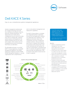


© Copyright 2026