
AE 64 – AVIONICS QUESTION BANK
AE 64 – AVIONICS QUESTION BANK DEPARTMENT OF AEROSPACE ENGINEERING, NOORULISLAMUNIVERSITY 2011 Questions and Answers Bank AVIONICS ,Semester:6 Prepared by N.Subash (Lecturer, Department of Electronics And Communication Engineering, Noorul Islam University). DEPARTMENT OF AEROSPACE ENGINEERING, NOORUL ISLAM UNIVERSITY 2011 Questions and Answers Bank AVIONICS Prepared by N.Subash (Lecturer, Department of Electronics And Communication Engineering, Noorul Islam University). Unit-I Part-I 1. Define the term Avionics systems. Ans:- All electronic and electromechanical systems and subsystems (hardware and software) installed in an aircraft that are dependent on flight crew to carry out the aircraft mission safely and to meet the mission requirements with minimum flight crew 2. Explain briefly Flight management system (FMS) Ans:- Outputs from the GNSS sensors, air data sensors and other on-board sensors are used by FMS to perform the necessary navigation calculations and provide information to the flight crew via a range of display units. The flight management system provides the primary navigation, flight planning, and optimized route determination and en route guidance for the aircraft and is typically comprised of the following interrelated functions: navigation, flight planning, trajectory prediction,performance computations, and guidance. To accomplish these functions the flight management system must interface with several other avionics systems. 3. Explain FBW control system. Ans: Enables a lighter, higher performance aircraft designed with relaxed stability. Good consistent handling which is sensibly constant over a wide flight envelope and range of load conditions Continuous automatic stabilization of the aircraft by computer control of the control surfaces. Auto pilot integration Care free maneuvering characteristics Ability to integrate additional controls automatically such as o Leading edge slats/flaps and trailing edge flaps to generate additional lift o Variable wing sweep o Thrust vector control nozzles and engine thrust Elimination of mechanical controls runs - friction, backlash Small control stick Ability to exploit aerodynamically unstable configuration Aerodynamics versus stealth - the concept of reducing the radar cross section Very high integrity, a failure survival system. 4. What do you mean by House keeping management? Ans:- The term 'house keeping' management has been used to cover the automation of the background tasks which are essential for the aircraft's safe and efficient operation Such tasks include Fuel management Electrical power supply system management Cabin/cockpit pressurization systems Environmental control system Warning systems Maintenance and monitoring systems. 5. What are the main characteristics of touch screens? Ans:- Fully Connected Speech Must Be Able to Operate in the Cockpit Environment Vocabulary size - required size is around 200-300 words Speech template duration - Speech Template Duration is around 5 Seconds Vocabulary duration - Maximum duration of the total vocabulary is around 160 seconds Syntax nodes - max. no. of syntax nodes required is 300 Duration of utterance - no restriction on the max. duration of an input utterance Recognition response time - this must be in real time. 6. What is the function of inertial sensor systems? What are the various inertial sensor systems used in aircraft? Ans:- They provide attitude and heading information which are essential for a/c mission. Various inertial sensor systems are- Gyros - mechanical electromechanical - RLG-FOG Accelerometer. AHRS(Attitude Heading Reference Systems) o Strap Down o Gimballed systems 7. Explain Radar systems. Ans:-• Installed in all civil airliners & in many general aviation aircraft • To detect water droplets and provide warning of storms, cloud turbulence and severe precipitation-aircraft can alter course and avoid such turbulent conditions • It should be noted that in severe turbulence, the violence of the vertical gusts can subject the aircraft structure to very high loads and stresses • These radars can also generally operate in ground mapping and terrain avoidance modes. • In the airborne interception mode, the radar, must be able to detect aircraft upto 100 miles away and track while scanning and keeping tabs on several aircraft simultaneously • The radar must also have a 'look down' capability and be able to track low flying aircraft below it. 8. What are the different methods of navigation? Ans:- Classic dead-reckoning navigation using air data and magnetic, together with Doppler or LORAN-C; Radio navigation using navigation aids – ground-based radio-frequency beacons and airborne receiving and processing equipment; Barometric inertial navigation using a combination of air data and inertial navigations (IN) or Doppler; Satellite navigation using a global navigation satellite system (GNSS), more usually a global positioning system (GPS); Multiple-sensor navigation using a combination of all the above. 9. Explain briefly radio navigation. Ans:- The primary means of navigation over land was by means of radio navigation routes defined by VHF omni ranging/distance measuring equipment (VOR/DME) beacons. By arranging the location of these beacons at major navigation or crossing points, it was possible to construct an entire airway network that could be used by the flight crew to define the aircraft flight from take-off to touchdown. Other radio frequency aids include distance measuring equipment (DME) and nondistance beacons (NDB). 10. Describe briefly inertial navigation Ans:- Using inertial navigation systems (INS), flight crew are able to navigate by autonomous means using an on-board INS with inertial sensors. By aligning the platform to earth-referenced coordinates and present position during initialization, it is possible to fly for long distances without relying upon LORAN, VOR/DME or TACAN beacons. Waypoints could be specified in terms of latitude and longitude as arbitrary points on the globe, more suited to the aircraft’s intended flight path rather than a specific geographic feature or point in a radio beacon network. 11. What do you mean by Engine control and management? Ans:-Control and the efficient management and monitoring of the engines Automatically controls the flow of fuel and respond to throttle command Control system ensures the engine limits in terms of temperatures, engine. speeds and accelerations are not exceed and the engine respond in an optimum manner to the throttle command. Full authority in terms of the control it can exercise on the engine and a high integrity failure survival 12.Explain the term Avionics systems . A system in aircraft is dependent on electronics for its operation, although the system may contain electromechanical elements is called avionics systems. All electronic and electromechanical systems and subsystems (hardware and software) installed in an aircraft or attached to it. (MIL-1553A-HDBK) 2. Equipments in Avionics systems are different from ground based equipments in many ways. Justify. 1. The importance of achieving minimum weight. 2. The adverse operating environment particularly in military aircraft in terms of operating temperature range, acceleration, shock, vibration, humidity range and electro-magnetic interference. 3. The importance of very high reliability, safety and integrity. 4. Space constraints particularly in military aircraft requiring an emphasis on miniaturisation and high packaging densities. 13.What are the major drivers for Avionics systems in a typical civil transport aircraft? The avionics systems are essential to enable the flight crew to carry out the aircraft mission safely and efficiently. The mission is the carrying of the passengers to their destination in the case of a civil airliner. Other important drivers for avionics systems are increased safety, air traffic control requirements, all weather operation, reduction in fuel consumption, improved aircraft performance and control and handling and reduction in maintenance costs . 14. List the various mission phases for military and civil aircraft. Mission phases --Air superiority --Ground Support --Passenger Transport 15. What are the typical Avionics system requirements for cruise phase and air-to-air military mission? Requirements for cruise phase ---Minimum Fuel Consumption ---Maximum Range --Maximum Endurance ---Accurate Navigation, Guidance and Control 16. What are the top level requirements for designing avionics systems in a civil aircraft? The aircraft manufacturer makes a very careful analysis of the potential customer structure, image, and operating philosophies to determine the customer future operating environment. The manufacturer then designs an aircraft that provides an optimum, balance response to the integrated set of needs Safety is always the highest priority need and economical operation is a close second 16. What are the steps involved in Avionics system design? 1. Requirement Analysis 2. Preliminary design 3. Detailed design 4. Testing and maintenance 16. Why weight saving is important in aircraft? A weight saving of 10 kg enables an increase in the payload capability of the order of 100 kg. 17. List the functions carried out by the FMS(Flight Management System) Flight Planning Navigation Management Engine control to maintain the planned speed of mach number Control of the aircraft flight path to follow the optimised planned route. Minimising fuel consumption 18. Briefly describe about the communication systems used in aircraft. The communication radio suite on modern aircraft is a very comprehensive one and covers several operating frequency bands. Long range communication is provided by high frequency radios operating in the band 2 – 30 Mhz. Near to medium range communication is provided in civil aircraft by very high frequency (VHF) radios operating in the band 30-100 Mhz, and in 19. What are the advantages of system integration by using digital data buses? It reduces the no of wiring requirements for integrating the subsystems. So that it reduces the faults and weight of the total system Greater information sharing can be achieved between subsystems 20. Define the term LRU? Line Replacement Unit, a single stand-alone unit with a unique part number that can be installed or removed from an aircraft by line maintenance personnel while the aircraft is on the flight line Unit-II Part-A 1. What is sampling frequency? Sampling is a process of converting continuous time signals into discrete time signals. The time period between two successive samples are called as sampling period (Ts). Sampling Frequency (Fs) is equal to 1/Ts. 2. List few advantages of digital systems over analog systems . Hardware Economy Reduction in weight and volume is of the order of 5:1 for a system of modest complexity Flexibility Control laws and gains can be changed Reduced nuisance disconnects Sophisticated voting and consolidation algorithms enable unwanted disconnections of redundant systems Built in test capability Comprehensive self test capabilities Digital data buses Large reduction in weight, high integrity data transmission 3. Discuss the problems encountered in digital data. 1. Aliasing 2. Quantization Noise 4. Describe flip-flop as a storage element . Flip-Flop is a memory element which is capable of storing one bit binary information 5. Give some features of 8085 microprocessor. 1. It is an 8-bit Microprocessor. 2. It has 16 address lines, hence it can access 64 Kbytes of memory. 3. It provides 8 bit I/O addresses to access 256 I/0 ports 4. It supports 74 instructions with the following addressing modes: a) Immediate addressing b) Register addressing c) Direct addressing d) Indirect addressing e) Implied addressing 6. What is the function of Program Counter? The program Counter is a special purpose register which, at a given time stores the address of the next instruction to be fetched. Program counter acts as a pointer to the next instruction . 7. What is the function of instruction decoder? The processer first fetches the opcode of instruction from the memory and stores this opcode in the instruction register. It is send to the instruction decoder. The instruction decoder decodes it and accordingly gives the timing and control signal which controls the register, the data buffers, ALU and external peripheral signals depending on the nature of the instruction. 8. Explain the function of interrupts. A more desirable method would be the one that allows the microprocessor to be executing its main program and only stop to service peripheral devices when it is told to do so by the device itself, In effect, the method, would provide an external asynchronous input that would inform the processer that it should complete whatever instruction that is currently being executed and fetch a new routine that will service the requesting device. Once this servicing is completed, the processer would resume exactly where it left off. This method is called interrupt method. 9. What is the difference between Microprocessors and Microcontrollers? Microprocessors 1. Microprocessor contains ALU, general purpose registers, stack pointer, program counter, clock Microcontrollers . Microcontroller contains the circuitry of microprocessor and in addition it has built-in ROM, RAM, I/O devices, timers and counters . Less flexible in design point of view. . Microcontroller based system requires less hardware reducing PCB size and increasing the reliability. 10. What is memory mapping? Memory mapping is a process of connecting external memory to the microprocessor. It gives the starting address and ending address of the connected memories 11. What are the needs of memory address lines? The memory capacity is directly proportional to the no of address lines. If memory is having 12 address lines and data lines, then Number of registers/memory locations = 4096. Microprocessor 8085 can access 64Kbytes memory since address bus is 16-bit. But it is not always necessary to use full 64Kbytes address space. The total memory size depends upon the application. 12. What is memory word size? 1 word = 8 bits 13. What are the classifications of memories? Memory . Read Only Memory(ROM) . Masked ROM . PROM . EPROM . EEPROM . Read/write memory(RAM) . Static RAM . Dynamic RAM 14. What is aliasing affect? When, the spectrum of the samples overlapping with each other. This is called aliasing effect = maximum frequency component present on the signal 15. What is the difference between volatile and non-volatile memory? The volatile memory retains its contents after switch off the power supply. But the non-volatile memory losses its contents when the power is switched off. 16. What is the function of multiplexer? A multiplexer is a digital switch which routes inputs from several sources to only one sink. The selection of input is achieved by suitable bit combinations of selection lines 17. What is the purpose of accumulator in Intel 8085 microprocessor? Registers are small memories within the CPU. They are used by the microprocessor for temporary storage and manipulation of data and instructions. The register A is the accumulator in Intel 8085 microprocessor. This is for temporary storage used during the execution of a program. It holds one of the operands. The other operand may be either in the memory or in one of the registers. 18. What are the status flags in 8085 microprocessor? Ans:- The following status flags have been provided in Intel 8085: (i) Carry(CS):- If there is a carry from addition or a borrow from subtraction or comparison, the carry flag CS is set to 1; otherwise 0. (ii) Zero(Z):- The zero status flag Z is set to 1 if the result of an arithmetic or (iii) Sign(S):- The sign status flag is set to 1 if the most significant bit of the result of an arithmetic or logical operation is 1, otherwise 0. (iv) Parity(P):- The parity status flag is set to 1 when the result of the operation contains even number of 1s. It is set to 0 when there is odd number of 1s. (v) Auxillary Carry(AC):- The auxillary carry status flag holds carry out of bit 3 to 4 resulting from the execution of an arithmetic operation. 19. What is the purpose of the ALE output line in 8085 µP? Ans:- ALE is an address latch enable signal. The 8085 microprocessor, to work properly, needs one or more memory chips connected to it. Each memory chip has its own MAR(Memory address register), usually called an address latch. This latch stores the incoming address from the address bus and address-data bus. The falling edge of the ALE signal loads the address on the address bus into the MAR or address latch of the memory chips. 20. What is the size of the memory space for an 8-bit microprocessor with a 16-bit address word? Ans:- 216 (= 65536=64Kilobytes(K), where 1K=1024 bytes) memory locations can be addressed by an 8-bit microprocessor with a 16-bit address word. Each memory location contains 1 byte of data. 21. State the functions of the following lines in 8085 µP chip, (i) SOD, SID (ii) READY Ans:- (i) Some times, I/O devices work with serial data rather than parallel. SOD stands for serial out data. This serial data comes out of pin 4, can be connected to a serial output device. SID stands for serial in data. (ii) Some peripheral devices are slow; they are unable to run at the same speed as 8085. One way to slow down the 8085 is with the READY signal. If the device is not ready, it will return a low READY bit to the 8085. The 8085 then generates a number of WAIT states. When the peripheral device is ready, it will send a high READY signal to µP. Then µP can complete the data transfer. 22. How is address information outputted in 8085 microprocessor? Ans:- The Intel 8085 requires a 16-bit wide address bus as the memory addresses are of 16 bits. The 8 most significant bits of the address are transmitted by the address bus, A-bus(pins A8 to A15). The 8 least significant bits of the address are transmitted by address/data bus, AD-bus moment, it transmits either data or address. This technique is called multiplexing. First of all 16-bit memory address is transmitted by the microprocessor; the 8 MSBs of the address on the A-bus and the 8 LSBs of the address on AD-bus. Then the 8 LSBs of the address is latched so that the complete 16-bit address remains available for further operation. 23. Define Opcode and Operand, and specify the Opcode and the Operand in the instruction MOV A, B. Ans:- Each instruction contains two parts: operation code(opcode) and operand. The first part of an instruction which specifies the task to be performed by the computer is called opcode. The second part of the instruction is the data to be operated on, and it is called operand. The operand given in the instruction may be in various forms such as 8-bit or 16-bit data, 8-bit or 16-bit address, internal registers or a register or memory location. In the instruction, MOV A, B, MOV is the opcode and A & B are operands. 24. Explain (i) One byte instruction (ii) Two byte instruction Ans:- A digital computer understands instructions written in binary codes or machine codes. The machine codes of all instructions are not of the same length. The instructions whose word size is of one byte (8 bits) are called one byte instructions. Eg:- MOV A,B The instructions whose word size is of two bytes (16 bits) are called two byte instructions. Eg:- MVI A, 05 25. Differentiate between Direct and indirect addressing. Ans:- In direct addressing mode, the address of the operand is given in the instruction itself. Eg: STA 2400H--------Store the content of accumulator in location 2400H. In indirect addressing mode, the address of the operand is not given in the instruction explicitly. Eg: RST 4----------------This instruction takes the program to the address 0020(4 x8=32)-------> (0020)hex. 26. What operations can be performed with the following instructions, (i) DAA (ii) DAD Ans:- (i) DAA instruction is used in the program after ADD or ADC hexadecimal and it is placed in the accumulator. DAA instruction operates on this result and gives the final result in decimal system. (ii) During the execution of DAD B instruction, the contents of B-C register pair are added to the contents of H-L pair and the sum is placed in H-L pair. 27. Differentiate between hold and halt states of the 8085 microprocessor. Ans:- If the HOLD line of 8085 found high, the µP enters a HOLD state and issues out a HLDA(Hold acknowledge) signal. After recognizing the HOLD signal, the µP suspends executing any further machine cycles and tri-states the A and AD buses and also the IO/M, RD and WR lines. During the HOLD state, the peripheral devices can gain control of the data and address buses for transferring data to or from the memory directly. This mode of operation is called Direct memory access(DMA). When a HLT instruction is executed, the µP enters a HALT state. It will stops the microprocessor. The registers and status flags remain unaffected. The µP can get out of this state only one clock cycle after a valid interrupt is recognized or a RESET occurs. 28. What is WAIT state? Some peripheral devices are slow; they are unable to run at the same speed as 8085. One way to slow down the 8085 is with the READY signal. If the device is not ready, it will return a low READY bit to the 8085. The 8085 then generates a number of WAIT states. When the peripheral device is ready, it will send a high READY signal to µP. Then µP can complete the data transfer. 29. What are the major components of a CPU? Ans: - The major components of CPU are:(1) Arithmetic and Logic Unit (ALU):- The function of ALU is to perform arithmetic operations such as addition and subtraction; logical operations such as AND, OR and EX-OR. (2) Timing and control unit:- It generates timing signals for the execution of instruction and control of peripheral devices. (3) Accumulator and General purpose registers:- The accumulator is a register which contains one of the operands and stores results of most arithmetic and logical operations. General purpose registers are used for temporary storage of data and intermediate results while computer is making execution of a program. 30. List the different categories of instructions that manipulate data. Ans: - Data transfer group, Arithmetic group, Logical group, Branch control Data transfer group:- Instructions which are used to transfer data from one register to another register, from a memory location to a register or register to memory, between an I/O device and accumulator or between a register pair and stack come under this group. Arithmetic group: The instructions of this group perform arithmetic operation such as addition, subtraction, increment or decrement data in register or memory. Logical group:- The instructions under this group perform logic operations such as AND, OR, compare, rotate etc. Branch Control group:- It includes the instructions for conditional and unconditional jump, subroutine call and return and restart. I/O and machine control group:- This group includes the instructions for input/output ports, stack and machine control. 31. Explain subroutines Ans:- While writing a program, certain operations may occur several times and they are not available as individual instruction. The program of such operations is repeated again and again in the main program. The concept of subroutines is used to avoid the repetition of smaller programs. The small programs for particular tasks are called subroutines. They are written separately and stored in the memory. They are called at various points of the main program by CALL instruction where they are required. After the completion of a subroutine, the main program begins from the instruction immediately following the CALL instruction. 32. Differentiate between maskable and non-maskable interrupts. Ans:- At many occasions, the programmer may like to prevent the occurrence of a few of several interrupts while µP is performing certain tasks. This is done by masking off those interrupts which are not required to occur when certain task is being performed. The interrupts which can be masked off are called maskable interrupts. Eg:- RST 7.5, RST 6.5 & RST 5.5. The TRAP is a non-maskable interrupt. It need not be enabled. It cannot be disabled.It is not accessible to user. It is used for emergency situation such as power failure and energy shut off. 33. What is memory mapped I/O scheme? Ans: - In this scheme, the addresses for I/O devices are different from the addresses which have been assigned to memories. The memory addresses which have not been assigned to memories can be assigned to I/O devices. both memory as well as I/O devices. Eg:- MOV A,M will be valid for data transfer from the memory location or I/O device whose address is in H-L pair. If the H-L pair contains the address of a memory location data will be transferred from the memory location to the accumulator. If the H-L pair contains the address of an I/O device, data will be moved from the I/O device to the accumulator. 34. Describe flip flop as a storage element. Ans:- A digital computer needs devices which can store information. A flip flop is a binary storage device. It can store binary bit either 0 or 1. It has two stable states: HIGH and LOW, ie 1 and 0. It has the property to remain in one state indefinitely until it is directed by an input signal to switch over to other state. It is a basic memory element. In the case of Dflip flop, when CLK is high, the flip flop sets. When CLK is low, the flip flop resets. Unit_III Part-A 1. What is the need for two different speeds in ARINC429? ARINC429 operates at two different speeds. There are 1. Low Speed(12 – 14 kbps) For general purpose low critical applications High Speed(100Kbps) For flight critical applications 2. Differentiate between centralized, Federated and Distributed architectures Centralized Signal conditioning and computation take place in one or more Computers in a LRU located in an avionics bay, with signals transmitted over one way data bus Federated Data conversion occurs at the system level and the data digital form – called Digital Avionics Information Systems (DAIS) Distributed It has multiple processors throughout the aircraft that are designed for computing takes on a real-time basis as a function of mission phase and/or system status. Data Processing is performed in the sensors and actuators. 3.What is the need for Manchester II Bi-phase encoding? It provides a self-clocking waveform with equal positive and negative values and suitable for transformer coupling 4.What is DATAC? Digital Autonomous Terminal Access Communication (DATAC). A carrier sense, multiple access, collision avoidance two-way data bus concept with an operating frequency and word structure identical to MIL-STD-1553B data buses but without a bus controller. Now it is called ARINC629. 5.What is distributed architecture? It has multiple processors throughout the aircraft that are designed for computing takes on a real-time basis as a function of mission phase and/or system status. Data Processing is performed in the sensors and actuators. 6.In Which Data Bus Dynamic bus – control acceptance is used and why? Dynamic bus – control acceptance is used in MIL-STD-1553B. The operation of a data bus system in which designated terminals is offered control of the data bus (The bus controller gives permission to another terminal for act as a Bus Controller). 7.What are the similarity between ARINC 629 and MIL-STD-1553B? Carrier Sense Multiple Access/ Collision Avoidance (CSMA/CA). Each and every terminal on the bus transmits the data autonomously without a Bus Controller. 9.What is the difference between Simplex bus and Duplex bus? In simplex mode, the communication is unidirectional, as on a one way street. Only one of the two stations on a link can transmit; the other can only receive. Keyboards and traditional monitors are both examples of simplex devices. The keyboard can only introduce input; the monitor can only accept output. In half duplex mode, each station can both transmit and receive, but not at the same time. When one device is sending, the other can only receive, and vice versa. Walkie-talkies and CB (citizen -duplex systems. 10. What are the couplings methods used in MIL-STD-1553B and write the difference between them? 1. Transformer Coupling 2. Direct Coupling Differences The primary difference between the two beings that the transformer coupled method uses an isolation transformer for connecting the stub cable to the main bus cable. In the direct-coupled method, the resistors are typically located within the terminal, whereas in the transformer-coupled method, the resistors are typically located with the coupling transformer in boxes called data bus couplers. Another difference between the two coupling methods is the length of the stub. For the direct-coupled method, the stub length is limited to a maximum of one foot. For the transformer-coupled method, the stub can be up to a maximum of twenty feet long. 11.What are the disadvantages of MIL-STD-1533B Data bus? Certification is a biggest problem present in MIL-STD-1533B.Single point failure in 1553B leads to certificability problem in civil aircraft and Addition of remote terminal requires changes in BC software which requires frequent certification standard 12.What is centralized architecture? A system design characterized by signal conditioning and computations are taking place in one computer or several very tightly coupled computers in (usually) one line replaceable unit located in the avionics bay, with signals transmitted over one-way data bus. 13.What is Time division Multiplexing Access? TDM enables information from several signal channels to be transmitted through one communication system by staggering the different channel samples in time to form a composite pulse train. Each signal channel is transmitted as a serial digital pulse train at a given time slot in a clock cycle. Thus given the clock time information and the address of the signal (suitably pulse coded), the receiver can then decode and distribute the individual signals. Hence if there are, say, 30 different signals to be transmitted between two units, only two wires are required in principle when the data is multiplexed compared with 60 wires. 14. Briefly explain the evaluation Avionics Systems Architecture. First Generation Architecture (1940 –1950 Disjoint or Independent Architecture ( MiG-21) Centralized Architecture (F-111) Second Generation Architecture (1960 –1970 Federated Architecture (F-16 A/B) Distributed Architecture (DAIS) Hierarchical Architecture (F-16 C/D, EAP) Third Generation Architecture (1980 –1990 Pave Pillar Architecture ( F-22) Fourth Generation Architecture (Post 2005) Pave Pace Architecture- JSF Open System Architecture 15.. What is protocol? Protocol is a set of formal rules and conventions governing the control of interaction 2. High-level protocol It deals with the data formatting, including the syntax of messages and its format. 16. What is the function of instrumentation bit? The instrumentation bit, in position 10, always shall be set to a logical 0 to allow distinction of a status word from a command word. (In a command word bit 10 is always set to a logical 1 if the instrumentation bit is being used.) 17. Explain Manchester-II-bi-phase encoding? A bi-phase method of encoding binary digits. A binary 1 begins with a positive voltage and swings negative at mid-bit. A binary O begins with a negative voltage and swings positive at mid-bit. 18. What is the function of mode code „00000 Dynamic Bus Control. Dynamic bus – control is used in MIL-STD-1553B. The operation of a data bus system in which designated terminals is offered control of the data bus. (The bus controller gives permission to another t erminal for act as a Bus Controller). 19. Why MIL-STD 1553 is not used in civil aircrafts? Getting certification for civil aircraft is very difficult comparing to military aircraft. Single point failure in 1553B leads to certificability problem in civil aircraft. Addition of remote terminal requires changes in BC software which requires frequent certification. 20. What are the disadvantages of Centralized architecture? 1. Vulnerability – „all the eggs in one basket computer affected all the subsystems sharing its computing facilities. 2. Inflexibility – changes in an individual sub – system could involve changes in the main computer software with possible ramifications and „knock on sub – systems sharing the computing facility. 3. Cost and weight of redundant central computer configurations was unacceptable. 21. What are the functions of Mode codes in MIL-STD1553B data bus? Mode codes are used only to communicate with the bus hardware and to manage information flow, not to transfer data. 22. Differentiate between MIL and ARINC 429 standard in terms of RT? MIL-STD-1553B All the remote terminals can able to transmit and receive the data Maximum no of remote terminals is 31 ARINC All the remote terminals can only receive the data Maximum no of remote terminals is 20 23. What is the function of status word in MIL-STD-1553B? The status words are used to give information about the status of the subsystems . 24. What is the function of Source destination Identifier (SDI) bit in ARINC429? ARINC429 is a Simplex Data Bus using only one transmitter and up to 20 data receivers. • To identify which source in the multisystem is transmitting the data • To direct which sink in the multisystem should recognize the data 25. Explain briefly magnetic bubble type memories. Ans:- Magnetic bubble type memory is a solid state device having high reliability, small size, light weight, ruggedness and limited power dissipation. It is a static device. It has no rotary parts. It has very high storage capacity in compact space. It is a non-volatile semi-random access type memory. It possesses the property of non-destructive read-out, which means that the read operation does not alter the stored information. It stores the data in magnetic bubbles created in a thin film of magnetic 26. Differentiate between semiconductor and magnetic memories. Ans:- Semiconductor memories are used as the main memory of a computer. They are faster, smaller, and lighter and consume less power. Magnetic memories are used as the secondary memories of a computer for bulk storage of data and information. They are slower, but cheaper than semiconductor memories. 27. What is the need for Manchester II bi-phase encoding? Ans: - In MIL-STD 1553 data bus, all words are constructed using Manchester coding. A logical 1 begins +ve and transitions to -ve at mid-bit and a logical 0 begins –ve and transitions to +ve at mid-bit. Manchester coding is chosen since it is compatible with transformer coupling and is self clocking. 28. Differentiate between Disjoint and Centralized Architectures. Ans:- In disjoint architecture, the system was integrated by the air-crew who had to look at various dials and displays connected to disjoint sensors, correlate the data provided by them, apply error corrections, orchestrate the functions of the sensors and perform mode and failure management in addition to flying the aircraft. In centralized architecture, a central computer was added to integrate the information from the sensors and subsystems. Data is transmitted from the systems to the central computer and the data conversion takes place at the central computer. 29. What are the three types of terminals in MIL-STD 1553 data bus? Ans:- The three terminals in MIL-STD 155 3 data bus are Bus Controller, Remote Terminal and Bus monitor.The bus controller is responsible for directing the flow of data on the bus.It initiates all information transfers. Bus controller also monitors the status of the system. A bus monitor receives and stores selected bus traffic. It will not respond to any traffic received, unless the traffic is specifically addressed to it. They are generally used to receive and extract data for off-line purposes such as flight test, maintenance or mission analysis. Remote terminals (RTs) are the largest fraction of units in a 1553 bus system. Because of the 5-bit address field, there can be only upto 31 RTs on a given bus. RTs respond only to valid commands specifically addressed to them or to valid broadcast commands.(all RTs simultaneously addressed) 30. What are the two coupling methods used in MIL-STD 1553 data bus? Ans:- Figure shows the two methods, the primary difference between the two for connecting the stub cable to the main bus cable. In both methods, two isolation resistors are placed in series with the bus. In the direct coupled method, the resistors are typically located within the terminal, where as in the transformer coupled method, the resistors are typically located with the coupling transformer in boxes called data bus couplers. Another difference between the two coupling methods is the length of the stub. For the direct coupled method, the stub length is limited to a maximum of 1 ft. For the transformer coupled method, the stub can be up to a maximum length of 20 ft. 31. Differentiate between command word and status word. Ans:- A command word is always the first word in a message and is transmitted only by the bus controller. Following the synchronization code, which is a + 112 bit times followed by a -112 bit times, there are 5 address bits. Every RT must have a unique address. The transmit/receive bit is set to logical 0 if the RT is to receive and to logical 1 if the RT is to transmit. The next 5 bits(10-14) are used to designate a subaddress to the RT or use of mode codes to the equipment on the bus. If bits 10 through 14 are subaddresses, bits 15 through 19 are the data word count. f bits 10 through 14 are either 00000 or 11111, bits 15 through 19 are mode codes. Bit 20 is parity bit. A status word is always the first word in a response by a remote terminal. Bit positions 1 through 3 are the synchronization code that is identical to that of a command word. Bits 4 through 8 are the address of the terminal transmitting the status word. Bits 9 through 19 are the RT status field. If the instrumentation bit in the status word is used, the available subaddresses are reduced to 15. Bit 20 is parity bit. 32. What is the function of bus controller in MIL-STD 1553 data bus? Ans:- The bus controller is responsible for directing the flow of data on the bus. It initiates all information transfers. Bus controller also monitors the status of the system. 33. What is the function of bus monitor in MIL-STD 1553 data bus? Ans:- A bus monitor receives and stores selected bus traffic. It will not respond to any traffic received, unless the traffic is specifically addressed to it. They are generally used to receive and extract data for off-line purposes such as flight test, maintenance or mission analysis. 34. What is the need of two different data rates in ARINC 429? Ans:- Two different data rates are used in ARINC-429. They are 12-14.5 is used for general-purpose, low criticality applications. High speed bus is used for transmitting large quantities of data or flight critical information. 35. Differentiate between Manchester encoding and bipolar-RZ encoding. Which encoding format is used in ARINC-429? Ans:- In Manchester coding, a logical 1 begins +ve and transitions to -ve at mid-bit and a logical 0 begins –ve and transitions to +ve at mid-bit. In bipolar return-to-zero encoding format, the voltage levels are used for representing logic 1 and 0 as shown in the figure. 36. What are the five primary fields in ARINC 429 word format? Ans:- ARINC-429 word format includes five primary fields, namely Parity, SSM, Data, SDI, and Label. Parity:- The MSB is always the parity bit for ARINC 429. Parity is normally set to odd except for certain tests. SSM:- Bits 31 and 30 contain the Sign/Status Matrix or SSM. This field contains hardware equipment condition, operational mode, or validity of data content. Data:- Bits 29 through 11 contain the data, which may be in a number of different formats such as BCD, BNR etc. SDI:- Bits 10 and 9 provide a Source/Destination Identifier or SDI. This is used for multiple receivers to identify the receiver for which the data is destined. Label:- The label is an important part of the message. It is used to determine the data type of the remainder of the word. All BCD and BNR data words have a five- character label assigned in 429. 37. How is ARINC-629 different from MIL-STD 1553? Ans:- ARINC-629 uses word formats that are very similar to those in MILSTD- 1553, but it does not have a bus controller. Instead, ARINC-629 gives each terminal autonomous access to the bus based upon meeting three timing conditions stored in a Transmit Personality programmable read-only memory, or PROM (XPP) in the host terminal. One of these timing conditions is unique to the terminal. Another difference from MIL-STD-1553 is the use of a Receive Personality PROM (RPP) to identify the labels of messages to be recorded from the bus. 38. Why we need different standards for military and civil aircraft data buses? Ans:- Once the equipments are standardized, equipments are easily Also safety measure is different for military and civil aircrafts. So we need different standards for military and civil aircrafts. Standardization of equipments are based on the document Military Standard (MIL-STD) and Aeronautical Radio Inc. (ARINC) specifications and Reports. 39. What are the functions of Terminal controller in ARINC-629? Ans:- Terminal controller provides Protocol Function and Data Validation. It acts as Subsystem/SIM Interface. It converts subsystem data to Manchester for SIM and decode Manchester data from SIM for subsystem. It also provides message and word sync pulses. It provides inter-word string gaps. 40. What are the functions of Serial Interface Module (SIM)? Ans:- Convert between Manchester < ----- > Doublets Transmit /Receive Doublets to/from Coupler Power Management - Apply /remove/reverse power - Over current detection and shutdown Fault Monitoring and Management - Checks its own output waveform - Checks received waveform - Causes/verifies coupler channel switching Inhibits coupler transmission, if necessary - Outputs fault information to Terminal Controller 41. What are the functions of current mode coupler in ARINC-629? Ans:- Provides Non-intrusive connection to the Bus Transmits/Receives Doublets onto/from the Bus Provides Low Impedance to Bus under all conditions Decodes SIM Doublet Polarity for Channel selection Provides appropriate Receive Doublet Polarity for SIM Shuts Down Transmitters on Power Reversal 42. Differentiate between Basic protocol and combined protocol. Ans:- Basic Protocol (BP) - Periodic Mode or Aperiodic Mode It provides an equal priority access for each terminal to transmit either periodic or aperiodic data. If no bus overload exists and transmission lengths are constant, terminals transmit at a constant interval (Periodic Mode). If the bus is overloaded, it will automatically switch to an aperiodic mode with no loss of data Combined Protocol (CP) - Periodic and Aperiodic Mode - Allows Prioritized Data levels of lower priority access for Aperiodic data transmission (Levels 2 & 3). At each level all terminals are given equal opportunity to access the bus. It allows substantial levels of aperiodic data to be transmitted without risk of affecting the frequency of periodic transmission. 43. The unique feature of ARINC 629 is that access to the bus to transmit by a given terminal is based on meeting three timing conditions. What are they? Ans:- The three timing conditions are Transmit Interval (TI), Terminal Gap (TG) and Synchronization Gap (SG). Transmit Interval (TI) is a global Bus Parameter. For a particular terminal, TI begins the moment the terminal starts transmitting. Once it has transmitted, it must wait the length of time specified by the TI before it can transmit again (0.5 to 64 ms).Terminal Gap(TG) is an unique timer assigned to each terminal on the Bus. TG begins only after the SG has elapsed and only if no carrier is present. TG and SG cannot overlap in time, they must run consecutively(4 to 128 µs). Synchronization Gap(SG) is a global access parameter. SG is the second longest timer and is set to the same value in all terminals. SG starts the moment the bus is quiet, it is reset if a carrier appears on the bus before it has elapsed. 44. Explain Synchronization gap. Ans:- The unique feature of ARINC 629 is that access to the bus to transmit by a given terminal is based on meeting three timing conditions. They are Transmit Interval (TI), Terminal Gap (TG) and Synchronization Gap (SG). Synchronization Gap is a Global Access Parameter. It is the second longest timer and is set to the same value in all terminals. SG starts the moment the bus is quiet, it is reset if a carrier appears on the bus before it has elapsed. 45. What do you mean by CID(Source channel identification)? Ans:- In ARINC-629, messages are composed of a series of word strings. The first word of any word string is the label word with its unique synchronization pattern followed by the Source channel identification (CID), the word string label and the parity bit. CID is used to identify a unique unit when there are two or more identical, redundant units on the same bus such as triple redundant inertial reference units Unit-IV DISPLAYS AND INTERFACES 1. What is a function of combiner in HUD? The optical element of the HUD through which the pilot views the outside world and which combines the collimated display image with the outside world scene is called combiner 2. What is instantaneous field of View? The angular coverage of the imagery which can be seen by the observer at any specific instant is called instantaneous field of View. 3. What is Total field of view? The total angular coverage of the display imagery which can be seen by moving the observer 4. What are the limitations of single element beam combiner HUDs? Transmission of the outside scene is higher in a single-element combiner than in a three – element combiner. 5. What are the advantages of three element beam combiner HUDs? A three element combiner design is used on some high performance aircraft to achieve better producibility, simpler overall HUD design, freedom from secondary reflections and large field of view 6. What are the advantages of HUDs? A HUD basically projects a collimated display in the pilots head up forward line of sight so that he can view both the display information and the outside world scene at the same time. There is no parallax errors and aiming symbols for either a flight path director, or for weapon aiming in the case of a combat aircraft, remain overlaid on a distant „target the pilot 1. Increased safety in landing the aircraft in conditions of severe wind shear 2. To display automatic landing guidance to enable the pilot to land the aircraft safely in conditions of very low visibility due to fog, as a back up and monitor for the automatic landing system. 7. Explain Label word Ans:- Label word is characterized by a synchronization pattern that starts in a high state and transitions to a low state in the middle of the second bit time. All other words follow the reverse pattern; thus the synchronization pattern alone is sufficient to identify a label word. For label words, the 16 bits between the synchronization pattern and the parity bit are designated as label bits (LBs). Label bits are numbered in reverse order from the basic word bit positions 8. Explain briefly about Light Emitting Diode (LED). Ans: - An LED is a solid- state device comprising a forward –biased p-n junction transistor formed from a slice or chip of gallium arsenide phosphate (GaAsP) mounted into a transparent covering. When the current flows through the chip it emits light which is in direct proportion to the current flow. Light emission in different colors of spectrum can be obtained by varying the proportions of the elements comprising the chip, and can also be obtained by using the technique called doping with other elements, e.g. Nitrogen. 9. What do you know about Liquid Crystal Display (LCD)? Ans: - LCD consists of two glass plates coated on their inner surfaces oxide. The material on the front plate is etched to form the seven segments, each of which forms an electrode. A mirror image is also etched into the oxide coating of the back glass plate. The space between the plates is filled with a liquid crystal compound, and the complete assembly is hermitically sealed with a special thermoplastic material to prevent contamination. 10. Explain the working of HUD. Ans: - A head-up display (HUD) is one in which vital in-flight data are presented at the same level as a pilot’s line of sight when he is viewing external references ahead of the aircraft. The principle adopted in a HUD system is to display the required data on the face of a CRT and to project them through a collimating lens as a symbolic image on to a transparent reflector plate, such that the image is superimposed on a pilot’s normal view, through the window screen, of the terrain ahead. The display is a combined alphanumeric and symbolic one, and since it is focused at infinity it permits simultaneous scanning of the ‘outside world’ and display without refocusing the eyes. 11. What are the properties of a Combiner? How it is constructed? Ans: The combiner is a mirror with several unusual properties: The reflective coating is highly wavelength selective, centered on the wavelength of the emission from the CRT phosphor and clear to other wavelengths, and the coating is also highly selective in angle of incidence so that only that light impinging within a very narrow range of angles will be reflected. Combiners are constructed photographically by exposing a film of dichromated gelatin to crossed laser beams and then developing the resulting diffraction pattern image. Since the gelatin is organic, it must be protected from the environment, especially from high temperatures. 12. Designing an HMD requires careful consideration of two factors. What are they? Ans: Two factors are:- Weight and Helmet aerodynamics. During high vertical acceleration maneuvers such as tight turns and ejection from the aircraft, the helmet can become a very heavy object, which leads to the mandate to design absolutely minimum-weight helmet mounted optics. Immediately following ejection, the helmet is exposed to a high-speed airflow which can generate substantial lift when flowing over a properly shaped object. Thus, the designer must ensure that the helmet is poorly designed any lift and thereby suddenly pull on the pilot’s neck immediately following ejection. 13. How multifunction keyboards can be designed using LEDs? Ans: Designs using LEDs have arrays of standard-sized push button switches with legends built into the surface of the switches. These legends are generated by small arrays of matrix addressable LEDs in the switch cover. Color can be used if desired. The legends are changed by the user or automatically by the aircraft as the mission phase changes. 14. How multifunction keyboards can be designed using LCDs? Ans: For MFKs designed using LCDs, the panel is usually a continuous smooth surface with the individual switch function and area established by the matrix addressed LCDs. Since LCDs have a graphics capability, it is also possible to enter a numerical value by pressing the surface of an LCD panel in the area where a portion of a curve is displayed rather than entering a numerical value by using a keyboard. 15. Explain multifunction displays. Ans: In multifunction displays, CRT displays serve as MFKs. The most common way is for the CRT face to contain function labels correlated with adjacent switches mounted in the bezel surrounding the CRT. It is easy through software to change the switch function and the associated label on the CRT. The second method of implementing MFKs on CRTs is to overlay the CRT face with a touch-sensitive screen. The CRT face contains various switch function legends and the corresponding function is selected by touching that portion of the screen over the switch label. 16. Explain DVI concept in cockpit. Ans: - Speech recognition systems are capable of performing non-critical tasks such as requesting system status, tuning radios, and requesting maps to be displayed on a CRT. The most important figure of merit in a speech recognition system is the fraction of correct word recognitions. When a word is spoken, there are three possible responses by the system: correct recognition, confusion with a rhyming word and rejection. Most systems can achieve correct recognition rates in the mid-90 percent in the case of a pilot experienced in interacting with a speech recognition system in a benign flight environment. As acceleration increases, the recognition rate decreases to less than 80% for a 9-g load on the pilot. Another important consideration individually, with a pause between successive words. 17. Explain voice synthesis systems. Ans: - The preferred use of voice synthesis systems is during high-work load periods. Messages should be brief and in a telegraphic format. Messages should be restricted to conditions that (1) require immediate corrective action or have an immediate impact on the safety of flight or (2) will soon reach this condition if not corrected by the pilot. These messages should be preceded by a warning tone and have a concurrent visual display. Voice synthesis systems must include logic in the central processor that will resolve conflicts between nearly simultaneously received messages to be converted into synthetic voice. This resolution is generally achieved by a first in first out protocol. 18. Explain Head Level displays? Ans: An HLD avoids the physiological limitation on eye refocusing time by placing directly below the HUD or top edge of the instrument panel a display in which an image and supplemental alphanumeric information are focused at a long distance. Thus, the need for the pilot to refocus his or her eyes to scan at least some information inside the cockpit is eliminated. Typically the HLD will contain a radar or infrared image of the outside scene. An HLD uses a high-intensity lamp coupled with dichroic filters to sort the white light into red, green and blue and with optics to collimate and fold the light. The red and green bands are each modulated by liquid crystal shutters in which each pixel is either opaque or transparent as required to generate a color image Part-B 1. Compare the different avionics system architectures and bring out their merits and demerits. Centralized Architecture Simple design Software can be written easily Computers are located in readily accessible bay Disadvantages Requirement of long data buses Low flexibility in software Increased vulnerability to change Different conversion techniques are needed at the central computer Federated Architecture 2.With neat-sketch Explain about the Pave-Pillar Architecture Increased Information Fusion Higher levels and complexity of software Standardization for maintenance simplification Lower costs Backward and growth capability while making use of emerging technology – VHSIC, Voice Provides capability for rapid flow of data in, through and from the system as well as between and within the system Higher levels of avionics integration and resource sharing of sensor and computational capabilities Pilot plays the role of a WEAPON SYSTEM MANAGER as opposed to subsystem operator/information integrator Able to sustain operations with minimal support, fly successful mission day and night in any type of weather Face a numerically and technologically advanced enemy aircraft and defensive systems Advantages Component reliability gains Use of redundancy and resource sharing Application of fault tolerance Reduction of maintenance test and repair time Increasing crew station automation Enhancing stealth operation Wide use of common modules (HW & SW)) Ability to perform in-aircraft test and maintenance of avionics Use of VHSIC technology and Capability to operate over extended periods of time at austere, deployed locations and be maintainable without the Avionics Intermediate Shop 3. a) Compare and Contrast the characteristics of MIL-STD1553B, ARINC429 and ARINC629. S.No 1. Characteristics MIL-STD1553B ARINC 429 Data Rate 1Mbps 2. 3. 4. Word length Low speed (12.5 2 Mbps kbps) High Speed (100 kbps) 32 bits 20 bits 32 data words Simplex Half duplex 5. 20 bits Message length Transmission Half duplex mode Operation Asynchronous Encoding Manchester Bi Phase 7. Protocol 8. Transmission Media Coupling 5. 9. 10 Maximum no terminals connected on the bus ARINC 629 Asynchronous Bi polar return to zero Asynchronous Manchester Bi Phase Command/Resp onse Twisted Pair cable Transformer and Direct coupling Point-to-point CSMA/CA Twisted Pair cable Direct coupling 31 20 Twisted Pair cable Current mode coupling ( Similar to transformer coupling) 120 Advantages Contrast to analog avionics – DDP provide precise solutions over long range of flight , weapon and sensor conditions Sharing of Resources Use of TDMA saves hundreds of pounds of wiring Standardization of protocol makes the interchangeability of equipments easier Allows Independent system design and optimization of major systems Changes in system software and hardware are easy to make Fault containment – Failure is not propagated 3. Explain the word formats of ARINC 629 Label Word System Status Word Function Status . Parameter Validity Word . . Explain the function of various timers in ARINC 629 . CSMA/CA is achieved by use of three timers Transmit Interval (TI) Terminal gap (TG) Synchronization gap (SG) Transmit Interval (TI) This timer is same for all terminals The timer starts every time the terminal starts transmitting a terminal has transmitted, it must wait the length of time specified by the TI before it can transmit again Terminal Gap (TG) Unique Timer assigned to each terminal on the Bus. It is used to differentiate between terminals since timer is unique. Thus timer starts only after the SG has elapsed and only if no carrier is present (for collision avoidance). This timer is reset by the presence of carrier. Synchronization Gap (SG) This timer is same for all terminals. It starts the moment the bus is quiet. It is reset if a carrier appears on the bus before it has elapsed (CARRIER SENSING). Once the timer has elapsed, it cannot be reset by the presence of a carrier. It can only be reset, when that terminal begins transmitting. Terminal Access Flow Chart Disadvantages Wastage of resources It is based on the TREE Topology Advantages Critical functions are placed in a separate bus and Non-Critical functions are placed in another bus Failure in non – critical parts of networks do not generate hazards to the critical parts of network The communication between the subsystems of a particular group are confined to their particular group The overload of data in the main bus is reduced 1. With neat sketch explain the operation of single element combiner and double element combiner HUD also give its advantages and disadvantages? Tree element combiner HUD It is used in high performance aircrafts Simpler overall HUD design Freedom from secondary reflections Large field of view. Part-A Unit-V 1. Explain Weather radar. Ans: • Installed in all civil airliners & in many general aviation aircraft • To detect water droplets and provide warning of storms, cloud turbulence and severe precipitation-aircraft can alter course and avoid such turbulent conditions • It should be noted that in severe turbulence, the violence of the vertical gusts can subject the aircraft structure to very high loads and stresses • These radars can also generally operate in ground mapping and terrain avoidance modes. • In the airborne interception mode, the radar, must be able to detect aircraft upto 100 miles away and track while scanning and keeping tabs on several aircraft simultaneously (typically at least 12 aircraft) • The radar must also have a 'look down' capability and be able to track low flying bands. The main role of electronic warfare is to search these radio-frequency bands in order to gather information that can be used by intelligence analysts or by frontline operators. The information gained may be put to immediate effect to gain a tactical advantage on the battlefield; it may be used to picture the strategic scenario in peace time, in transition to war, or during a conflict. It may also be used to devise countermeasures to avoid a direct threat or to deny communications to an enemy. The cycle of intelligence begins with a requirement to gather information on a particular scenario. Intelligence is collected from a number of different sources to form a strategic picture. 3. Explain the need of accurate navigation. Ans:Effective operation of any a/c Automatic because of speed Density of air traffic on major air routes to fly in a specified corridor defined by ATC authorities - high accuracy NAV is essential & forms part of FMS For military operation - to enable the a/c to fly low & take advantage of terrain screening from enemy radar Use of weapon - released from several Kms away from target also requires an accurate knowledge of the a/c position in order to indicate the mid course inertial guidance of the missile. 4. Describe the various dead reckoning navigation systems used in aircraft. Ans:- DR navigation systems used in aircraft are Air data/heading reference system - lower accuracy Doppler/heading reference systems - widely used in helicopters Inertial Navigation systems - most accurate and widely used systems Doppler/Inertial navigation system - combination 5. Explain radio navigation systems Ans:- Two types of radio navigation systems are position fixing systems and hyperbolic radio navigation systems POSITION FIXING SYSTEMS Range and bearing (R/q) radio navigation aids VOR/DME TACAN- Accuracy of 1-2 miles HYPERBOLIC RADIO NAVIGATION SYSTEMS LORAN C - positional accuracy of around 150 m 8 LORAN C chains comprising 34 6. Explain the various communication systems used in aircraft. Ans:- High-frequency (HF) communications; Very high-frequency (VHF) communications; Ultrahigh-frequency (UHF) communications; Satellite communications (SATCOM); Data links. 7. Differentiate between HF and VHF communication systems. Ans:- High frequency (HF) covers the communications band between 3 and 30 MHz and is a very common communications means for land, sea and air. The utilized band is HF SSB/AM over the frequency range 2.000–29.999 MHz using a 1 kHz (0.001 MHz) channel spacing. The primary advantage of HF communications is that this system offers communication beyond the line of sight. The VHF band for aeronautical applications operates in the frequency range 118.000– 135.975 MHz with channel spacing in past decades of 25 kHz (0.025 MHz). In recent years, to overcome frequency congestion and taking advantage of digital radio technology, channel spacing has been reduced to 8.33 kHz (0.00833 MHz) which permits 3 times more radio channels in the available spectrum. VHF signals will only propagate over line of sight. That is, the signal will only be detected by the receiver when it has line of sight or can ‘see’ the transmitter. This line-of-sight property is affected by the relative heights of the radio tower and aircraft. 8. Explain satellite communication systems. Ans:- Satellite communications provide a more reliable method of communications using the International Maritime Satellite Organization (INMARSAT) satellite constellation. The aircraft communicates via the INMARSAT constellation and remote ground earth station by means of C-band uplinks and downlinks to/from the ground stations and L-band links to/from the aircraft. In this way, communications are routed from the aircraft via the satellite to the ground station and on to the destination. Conversely, communications to the aircraft are routed in the reverse fashion. The airborne SATCOM terminal transmits on frequencies in the range 1626.5– 1660.5 MHz and receives messages on frequencies in the range 1530.0– 1559.0 MHz. The coverage offered by the INMARSAT constellation was a total of four satellites in 2001. Further satellites are planned to be launched in the near future. The INMARSAT satellites are placed in earth geostationary orbit above 9. Describe data links. Ans:- Many of the data links are limited to line-of-sight operation owing to the transmission characteristics of the RF frequencies being employed. However, the use of communications satellites to perform a relay function permits transmission of data over the horizon (OTH), thereby enabling intra- and inter-theatre communications. Typical data packages that may be delivered by data links include: Present position reporting; Surveillance; Aircraft survival, EW and intelligence information; Information management; Mission management; Status. The primary data links used for communications between airborne platforms and space and surface platforms areLink-16 - This is the most commonly used avionics data link and is usually manifested in avionics systems as the joint tactical information distribution system (JTIDS). Link-11 - a data link commonly used by naval forces. 16 marks: 1)Discuss the bus protocol in MIL-STD 1553B and the word formats. (16) Hint:- Bus protocol in MIL-STD-1553 includes message formats and word structure. Important message formats include BC-RT transfer, RT-BC transfer and RT-RT transfer. Three word formats include command word, status word and data word. Explain each of them as given in note 10. (i) Explain ARINC-629 protocols (8) Hint:- There are two ARINC-629 protocols. They are basic and combined. Explain each briefly as given in note (ii)Explain ARINC-429 word format (8) Hint:- ARINC-429 word format includes five primary fields, namely Parity, SSM, Data, SDI, and Label. Data, SDI, and Label. Bits 31 and 30 contain the Sign/Status Matrix or SSM. This field contains hardware equipment condition, operational mode, or validity of data content. (ii) Discuss the communication systems used in aircrafts. (8) Hint:- Various communication systems used in aircrafts include HF, VHF, UHF,SATCOM, Data links etc. 12. What are the advantages of Inertial Navigation Systems? It is completely self-contained navigation system. . High accuracy . It doesn 13What is electronic warfare? Electronic Warfare encompasses all actions involving the use of electromagnetic energy to DETERMINE, EXPLOIT, REDUCE Or PREVENT HOSTILE USE OF ELECTROMAGNETIC SPECTRUM and actions which RETAIN FRIENDLY USE of the electromagnetic Spectrum . 14. What is data fusion? It is the name given to the process of combining data from number of different sources to provide information which is not present in the individual sources . 15. What are the different types of communication systems in Aircraft? High-frequency (HF) communications; 2. Very high-frequency (VHF) communications; 3. Ultrahighfrequency (UHF) communications; 4. Satellite communications (SATCOM); 5. Data links . 16. What are the various classification of Navigation system?. 1. Navigation by Pilotage 2. Celestial Navigation 3. Navigation by Dead-Reckoning 4. Radio Navigation 5. Satellite Navigation 17. Justify the need for certification. Certification is a critical element in the safety-conscious culture on which civil aviation is based. The legal purpose of avionics certification is to document a regulatory judgment that a device meets all applicable regulatory requirements and can be manufactured properly 18. Describe Fly-by-Wire flight control systems? A flight control system where all the command and control signals are transmitted electrically and the aerodynamic control surfaces are operated through computers which are supplied with the pilots command signals and the aircraft state from appropriate motion sensors 19. Explain Electromagnetic Interference. 1. Any electromagnetic energy which interrupts, obstructs, or otherwise degrades or otherwise degrades or limits the effective performance of telecommunicating (communication-electronic) equipment. 2. 9. What is navigation? 3. Navigation is an art of finding the position of the vehicle with respect to some reference frame. 10. What is Celestial Navigation? Celestial Navigation is accomplished by measuring the angular position of celestial bodies. Almanacs giving the position of celestial bodies at various times are readily available. The navigator measures the elevation of the celestial body with a sextant and notes the precise time at which the measurement is made with a chronometer. These two measurements are enough to fix the position of the vehicle on a circle on the face of the globe. 11. What is dead-reckoning Navigation? In this method of navigation, the position of electromagnetic waves to find the position of the craft. All the systems depend upon the transmitters and receivers at known locations on the earth receivers working in co junction with them in a vehicle. This type of navigation depends on the external aids and it is not self contained The positional information may be related to 4. Measurement of direction 5. Measurement of distance 6. Difference of distance between two transmitters 20. What is satellite Navigation? The satellite navigation system depends on the measurement of the exact distance of the receiver from the satellite and the locus is the intersection of a spherical surface with the earth (or a concentric sphere in the case of aircraft flying over the earth). And again the intersection of two or more loci establishes the position of the receiver. 14. What is the difference between Navigation and Guidance? A navigation system is one that automatically determines the position of the vehicle with respect to some reference frame. A guidance system, on the other hand, automatically makes the necessary correction to keep the vehicle on course by Part B Unit-I 1. i) Explain the need for avionics in civil and military aircrafts. development and introduction of avionics systems navigator and Flight engineer. achievement of safe expenses and training costs. (Navigator/Observer/Radar-Operator) 1. ii) Explain integrated avionics systems and weapon systems (i)Explanation (ii)Diagram 2. i) What are the major design drivers for avionics system? designing a digital avionics system development methods in civil and military avionics. – The customer prepares the statement of need and top-level description of possible missions – The requirement describes the gross characteristic of a hypothetical aircraft that could fly the mission – The Customer may also describe the mission environment and define strategic and tactical philosophies and principles and rules of engagement. Top – level requirements for the successor to the A-10 Aircraft Minimum Goal 2.ii) Describe the various “illities” in avionics systems Survivability Capability of systems MIL-STD-2069 Maintainability MIL-STD-721C Vulnerability MIL-STD-2069 Accessibility 3. With a neat block diagram explain the integration of different avionics system. Major avionic systems „System Integration . 4. i) Explain clearly the top down design procedure that is adopted in Avionics system design The overall plan must contain the following 1) A detailed milestone chart 2) A synthesis and analysis plan 3) A verification plan 4) Flight safety, Reliability, Vulnerability and Maintainability analyses plans 5) A functional mock up test plan 6) A ground test plan including test procedures 7) A flight test plan including test procedures 6. Explain the Various Typical Avionics Sub systems. Displays pilot crew Airframe data Warning information Weapon aiming Threat warnings Unit-II 1. Explain the operation of digital computers INPUT/OUTPUT Central Processing Unit input/ output devices control unit. Arithmetic/ Logic Circuit MPU. 2.With Neat Sketch explain the architecture of 8085 Microprocessor The architecture of 8085 includes ALU, Timing and control unit , Instruction register and decoder , Register array, Interrupt Control and Serial I/O control. General purpose . . 3.Explain the different types of Interrupts and its functions in 8085 Vectored Interrupts Maskable and Nonmaskable interrupts 1) Hardware Interrupts 2) Software Interrupts Non-maskable interrupt It has highest priority Non Vectored interrupt b) INTR Maskable Interrupt Vectored Interrupt It has second Highest priority c) RST 7.5 Maskable Interrupt Vectored Interrupt It has second highest priority d) RST6.5 & 5.5 Maskable interrupt Vectored interrupt RST 6.5 has the third priority RST 5.5 has the fourth priority 4.Explain the method of Memory Interfacing, and various steps involved in interfacing memory devices with 8085 microprocessor. The memory interfacing requires 1. Select the chip 2. Identify the register 3. Enable the appropriate buffer 1) Connect the required address lines of the address bus to the address lines of the memory chip. 2) Decode the remaining address lines of the address bus to generate the chip select signal and connect the signal to select the chip. 3) Create control signals MEMR and MEMW by combining RD and WR signals with, IO/M, and use them to enable appropriate buffers. 5. Explain the method of I/O Interfacing, and various steps involved in interfacing I/O devices with 8085 microprocessor. Combine the device address pulse with the control signal to generate a device select (I/O select) pulse that is generated only when both signals are asserted. Use the I/O select pulse to activate the interfacing device (I/O port) Decode the address bus to generate the device address pulse. AND the control signal with the device address pulse to generate the device select pulse Use the device select pulse to enable the I/O port. Unit-III 1.Explain dead-reckoning navigation with one example Inertial Navigation Measurement of direction (RDF) Measurement of Distance (DME) . Difference of distance between two transmitters (LORAN, TACAN, etc) Space segment Almanac - Coarse time information Ephemeris – orbital Information Clock information C/A code ( available to public) – P-code ( reserved for US military purpose) Control Segment 2.. Explain the various functions involved in Electronic Warfare. Electronic Warfare encompasses all actions involving the use of electromagnetic energy to DETERMINE, EXPLOIT, REDUCE Or PREVENT HOSTILE USE OF ELECTROMAGNETIC SPECTRUM and actions which RETAIN FRIENDLY USE of the electromagnetic Spectrum. Divisions of Electronic warfare Signals Intelligence Intelligence is collected from a number of different sources to form a strategic picture. These sources include: Electronic Intelligence Communication Intelligence Electronic Intelligence 2. Image Intelligence 3. Photographic intelligence The locations of groups of transmitters and the numbers in the groups The frequency of the transmitter carrier The style of the operator The relative intensity of messages. Electronic Support measures (ESM) ESM is that division of EW involving actions taken to search for, I ntercept, locate and immediately identify radiated electro-magnetic energy for the purposes of immediate thread recognition and the tactical employment of forces. It has the following divisions Threat warning Electronic Counter Measures (ECM) Electronic counter measures encompass all actions taken to introduce signals into an electronic system which degrades the performance of that system so that it is unable to perform its intended mission. It has the following divisions Noise Jamming Deception Jamming 1. Noise Jamming Injects an interference signal into the enemy actual signal is completely submerged by the interference. Optimum jamming signal should have the characteristics of victim receiver noise. Minimum details of victim radar is required. Deception Jamming The objective is to mask the real signal by injecting a suitably modified replica of the real signal in to the victim radar system. Deception jamming attempts to jam victim radar both in range and in angle. Some deception jamming also attempts to jam velocity tracking circuits to prevent cross checking between Doppler measurements and differentiated range measurement. Electronic Counter-Counter Measures Electronic Counter-Counter measures all actions taken to introduce signals into an electronic system which prevents the performance of friendly ECM & ESM system so that it is able to perform its intended mission. It has the following divisions Anti-ESM Anti-ECM Transmitting more average power Increasing antenna gain Homing longer on the target – Reducing data rate – Adaptive scan rate . 3. Explain Maintenance and Reliability analysis of avionics systems and the various steps followed for reducing the difficulties involved in avionics system maintenance? Maintenance t .Who will be doing the work? Skill level of maintenance personnel is a major consideration This necessitates a straight forward design which can be easily understood with BITE, procedures and associated displays Experience level of military personnel will be substantially less than those of their civil counterparts When will it be done? Amount of time required for maintenance is one of the factor to be considered Reducing this time will yield an equal reduction in sortie turnaround time Architecture should be designed to allow the aircraft to be dispatched with an inoperative unit and repaired during a scheduled maintenance Where will it be done? Maintenance tasks may be performed in Flight line and Maintenance depot. Distribution of maintenance tasks between the flight line and the maintenance depot must be established easy in the design. The distribution will have a major influence on the design of built-in-test equipment and accessibility to the LRU 4.Designing for Easy Maintenance Use of standard units for design Accessibility of LRUs in both flight line and shop Each function should be implemented on asingle replaceable unit ESD sensitive devices should have protection facilities built in to the LRUs 1. BITE is a powerful maintenance tool that takes advantage of the intrinsic capabilities of digital avionics. BITE has become used in more LRU avionics architectures, there has been a trend toward the development of CFDS that display and store fault data for all BITE equipped LRU indispensable maintenance needs. BITE should be able to recognize and correctly identify at least 95% of possible faults. Failure of BITE should also be clearly indicated. Reliability The duration or probability of failure-free performance under stated conditions The probability that an item can perform its intended functions for a specified interval under stated conditions Well known method is to use failure prediction methods Rate gyroscopes : Rate of rotation about roll, pitch and yaw axes. Linear accelerometers : Normal and Lateral acceleration. Air data sensors : Height and Airspeed. Airstream sensors : Incidence angles in longitudinal and lateral planes. Features Electrical Signal Transmission . 4.Explain the requirements for Civil Avionics certification? a) The equipment, systems and installations whose function is required by this subchapter must be designed to ensure that they perform their intended functions under any foreseeable operating conditions. b) The airplane systems and associated components, considered separately and in relation to other systems, must be designed so that 1) The occurrence of any single failure condition which would prevent the continued safe flight and landing of the airplane is extremely improbable, and 2) The occurrence of any data failure condition which would reduce the capability of the airplane or the ability of the crew to cope with adverse operating conditions is improbable. c) Warning information must be provided to alert the crew to unsafe system operating conditions and to enable them to take appropriate corrective action. Systems, controls and associated monitoring and warning means must be designated to minimize crew errors which would create additional hazards. d) Compliance with the requirements of paragraph (b) of this section must be shown by analysis and where necessary, by appropriate ground, flight, or simulator tests. The analysis must consider 1) Possible mode of failure, including malfunctions and damage from external sources. 2) The probability of multiple failures and undetected failures. 3) The resulting effects on the airplane and occupants, considering the stage of flight and operating conditions, and 4) The crew warning cues, corrective action required, and the capability of detecting fault Unit-IV . 1. Compare the different avionics system architectures and bring out their merits and demerits. Centralized Architecture Simple design Requirement of long data buses Low flexibility in software Increased vulnerability to change Different conversion techniques are needed at the central computer Federated Architecture 2.With neat-sketch Explain about the Pave-Pillar Architecture Increased Information Fusion Higher levels and complexity of software Standardization for maintenance simplification Lower costs Backward and growth capability while making use of emerging technology – VHSIC, Voice Recognition /synthesis and Artificial Intelligence Provides capability for rapid flow of data in, through and from the system as well as between and within the system Higher levels of avionics integration and resource sharing of sensor and computational capabilities Pilot plays the role of a WEAPON SYSTEM MANAGER as opposed to subsystem operator/information integrator Able to sustain operations with minimal support, fly successful mission day and night in any type of weather Face a numerically and technologically advanced enemy aircraft and defensive systems Advantages Component reliability gains Use of redundancy and resource sharing Application of fault tolerance Reduction of maintenance test and repair time Increasing crew station automation Enhancing stealth operation Wide use of common modules (HW & SW)) Ability to perform in-aircraft test and maintenance of avionics Use of VHSIC technology and Capability to operate over extended periods of time at austere, deployed locations and be maintainable without the Avionics Intermediate Shop 3. a) Compare and Contrast the characteristics of MIL-STD1553B, ARINC429 and ARINC629. S.No 1. Characteristics MIL-STD1553B ARINC 429 Data Rate 1Mbps 2. 3. 4. Word length Low speed (12.5 2 Mbps kbps) High Speed (100 kbps) 32 bits 20 bits 32 data words Simplex Half duplex 5. 5. 20 bits Message length Transmission Half duplex mode Operation Asynchronous Encoding Manchester Bi Phase Asynchronous Bi polar return to zero ARINC 629 Asynchronous Manchester Bi Phase 8. 9. 10 Transmission Media Coupling Twisted Pair cable Transformer and Direct coupling Twisted Pair cable Direct coupling Maximum no terminals connected on the bus 31 20 Twisted Pair cable Current mode coupling ( Similar to transformer coupling) 120 Advantages Contrast to analog avionics – DDP provide precise solutions over long range of flight , weapon and sensor conditions Sharing of Resources Use of TDMA saves hundreds of pounds of wiring Standardization of protocol makes the interchangeability of equipments easier Allows Independent system design and optimization of major systems Changes in system software and hardware are easy to make Fault containment – Failure is not propagated 3.Explain the word formats of ARINC 629 Label Word System Status Word Function Status . Parameter Validity Word .5. Explain the function of various timers in ARINC 629 . CSMA/CA is achieved by use of three timers Transmit Interval (TI) Terminal gap (TG) Synchronization gap (SG) Transmit Interval (TI) This timer is same for all terminals The timer starts every time the terminal starts transmitting a terminal has transmitted, it must wait the length of time specified by the TI before it can transmit again Terminal Gap (TG) Unique Timer assigned to each terminal on the Bus. It is used to differentiate between terminals since timer is unique. Thus timer starts only after the SG has elapsed and only if no carrier is present (for collision avoidance). This timer is reset by the presence of carrier. Synchronization Gap (SG) This timer is same for all terminals. It starts the moment the bus is quiet. It is reset if a carrier appears on the bus before it has elapsed (CARRIER SENSING). Once the timer has elapsed, it cannot be reset by the presence of a carrier. It can only be reset, when that terminal begins transmitting. Terminal Access Flow Chart Disadvantages Wastage of resources It is based on the TREE Topology Advantages Critical functions are placed in a separate bus and Non-Critical functions are placed in another bus Failure in non – critical parts of networks do not generate hazards to the critical parts of network The communication between the subsystems of a particular group are confined to their particular group The overload of data in the main bus is reduced 1. With neat sketch explain the operation of single element combiner and double element combiner HUD also give its advantages and disadvantages? Tree element combiner HUD It is used in high performance aircrafts Simpler overall HUD design Freedom from secondary reflections Large field of view. 1. Compare the different avionics system architectures and bring out their merits and demerits. Centralized Architecture 6. . Explain the function of various timers in ARINC 629 . CSMA/CA is achieved by use of three timers Transmit Interval (TI) Terminal gap (TG) Synchronization gap (SG) Transmit Interval (TI) This timer is same for all terminals The timer starts every time the terminal starts transmitting a terminal has transmitted, it must wait the length of time specified by the TI before it can transmit again Terminal Gap (TG) Unique Timer assigned to each terminal on the Bus. It is used to differentiate between terminals since timer is unique. Thus timer starts only after the SG has elapsed and only if no carrier is present (for collision avoidance). This timer is reset by the presence of carrier. Synchronization Gap (SG) This timer is same for all terminals. It starts the moment the bus is quiet. It is reset if a carrier appears on the bus before it has elapsed (CARRIER SENSING). Once the timer has elapsed, it cannot be reset by the presence of a carrier. It can only be reset, when that terminal begins transmitting. Terminal Access Flow Chart Disadvantages Wastage of resources It is based on the TREE Topology Advantages Critical functions are placed in a separate bus and Non-Critical functions are placed in another bus Failure in non – critical parts of networks do not generate hazards to the critical parts of network The communication between the subsystems of a particular group are confined to their particular group The overload of data in the main bus is reduced Unit-V 1. With neat sketch explain the operation of single element combiner and double element combiner HUD also give its advantages and disadvantages? Tree element combiner HUD It is used in high performance aircrafts Simpler overall HUD design Freedom from secondary reflections Large field of view. 2. Explain dead-reckoning navigation with one example Inertial Navigation Measurement of direction (RDF) Measurement of Distance (DME) Difference of distance between two transmitters (LORAN, TACAN, etc) . Space segment Ephemeris – orbital Information Clock information – C/A code ( available to public) – P-code ( reserved for US military purpose) Control Segment 1. The spherical range of the user from the individual transmitting satellite can be determined by measuring the time delay for the satellite transmission to reach the user. Multiplying the time delay by the velocity of light then gives the spherical range ρ of the user from the transmitting satellite. The measurement of the time delay is thus made up of two components. The first component is the transit time of the ranging signal and the second component is the offset between the transmitter clock and receiver clock due to the nonsynchronization of the 2. clock. Measuring the spherical ranges from four satellites as shown in fig enables the user determined and yields four equations containing the four unknowns, viz the three position co-ordinates of the user and the time bias in the user d waveforms and illustrates the user time bias △T, and the time delays △t1, △t2, △t3, △t4 for the signals transmitted from the satellites to reach the user. 3. 4. The position of user can be find out by solving the below three simultaneous spherical equations. A Cartesian coordinate is constructed for the mathematical analysis of GPS operation by using earth centre of gravity as centre of axis system. The orbital position of the satellites satellite1, satellite2 and satellite3 are represented as (X1, Y1, Z1), (X2, Y2, Z2) and (X3, Y3, Z3). The user position on the earth can be represented as (Xu,Yu,Zu). Four pseudo ranges , , and to the four satellites satellite1, satellite2, satellite3 and satellite4 can be determined = C*△t1 = C* 5. Let the range equivalent to the user clock offset, The four spherical ranges,,and can be determined from the below spherical equations These four equations with four unknowns can thus be solved and yield the users position coordinates (Xu, Yu, Zu) and the users time offset △T. The satellite clocks are therefore mathematically synchronized to d defined GPS master time which is maintained at the master control station. n 3. Explain the various functions involved in Electronic Warfare. 1. Electronic Warfare encompasses all actions involving the use of electromagnetic energy to DETERMINE, EXPLOIT, REDUCE Or PREVENT HOSTILE USE OF ELECTROMAGNETIC SPECTRUM and actions which RETAIN FRIENDLY USE of the electromagnetic Spectrum. 2. Divisions of Electronic warfare Signals Intelligence Intelligence is collected from a number of different sources to form a strategic picture. These sources include: Electronic Intelligence Communication Intelligence Electronic Intelligence Confirmation of electronic warfare intelligence is usually performed by comparison with local information collection and photographic evidence, including 1. Human Intelligence 2. Image Intelligence 3. Photographic intelligence The human intelligence and image intelligence are often gathered by high-flying EW aircraft on long duration patrols, usually flying a patrol on the friendly side of a border and beyond missile engagement range. The photographic intelligence is used to obtain the existence and precise location and types of target. Communication intelligence 1. Communication intelligence is gathered by scanning the normal communication frequency bands and looking on to detected transmissions. In peace time it may be possible to receive in clear speech, but this is extremely unlikely in times of tension or during conflict. Howeve great deal of intelligence can be obtained from the following characteristics of communications activity. The locations of individual transmitters The locations of groups of transmitters and the numbers in the groups The frequency of the transmitter carrier The style of the operator The relative intensity of messages. Electronic Support measures (ESM) ESM is that division of EW involving actions taken to search for, intercept, locate and immediately identify radiated electro-magnetic energy for the purposes of immediate thread recognition and the tactical employment of forces. It has the following divisions Threat warning Homing Target Acquisition Electronic Counter Measures (ECM) Electronic counter measures encompass all actions taken to introduce signals into an electronic system which degrades the performance of that system so that it is unable to perform its intended mission. It has the following divisions Noise Jamming Deception Jamming 2. Noise Jamming Injects an interference signal into the enemy signal is completely submerged by the interference. Optimum jamming signal should have the characteristics of victim receiver noise. Minimum details of victim radar is required. Deception Jamming The objective is to mask the real signal by injecting a suitably modified replica of the real signal in to the victim radar system. Deception jamming attempts to jam victim radar both in range and in angle. Some deception jamming also attempts to jam velocity tracking circuits to prevent cross checking between Doppler measurements and differentiated range measurement. Electronic Counter-Counter Measures Electronic Counter-Counter measures all actions taken to introduce signals into an electronic system which prevents the performance of friendly ECM & ESM system so that it is able to perform its intended mission. It has the following divisions Anti-ESM Anti-ECM We know that the performance of the ESM and ECM can be degraded by noise jamming and deceptive jamming Increasing antenna gain Homing longer on the target – Reducing data rate – Adaptive scan rate Increase the transmitter frequency to narrow the antenna blanked by the main lobe noise jamming and also provides a strobe in the direction of the jammer. The effect of deception jamming is minimized by using the below techniques. The false target return must follow the return from the jammer carrying target and in any event must lie in the same direction within a radar pulse repetition interval. To encounter this radar employ leading edge tracker which tracks the target pulse which is ahead of false target pulse. If the deception jammer uses a delay which is greater than Pulse repetition interval to generate an anticipatory false target return, then pulse to pulse frequency agility eliminates the false targets and pulse to pulse PRI jitter identifies the false target returns . 4. Explain Maintenance and Reliability analysis of avionics systems and the various steps followed for reducing the difficulties involved in avionics system maintenance? Maintenance Measure of ability of an item to be retained in or restored to specified condition when maintenance This necessitates a straight forward design which can be easily understood with BITE, procedures and associated displays Experience level of military personnel will be substantially less than those of their civil counterparts When will it be done? Amount of time required for maintenance is one of the factor to be considered Reducing this time will yield an equal reduction in sortie turnaround time Architecture should be designed to allow the aircraft to be dispatched with an inoperative unit and repaired during a scheduled maintenance Where will it be done? Maintenance tasks may be performed in Flight line and Maintenance depot. Distribution of maintenance tasks between the flight line and the maintenance depot must be established easy in the design. The distribution will have a major influence on the design of built-in-test equipment and accessibility to the LRU Designing for Easy Maintenance Avionics designed for easy maintenance are major contributors for increasing the mission effectiveness while reducing operating costs Make maintenance manuals, procedures, and equipments easy to use and understand Use of standard units for design Accessibility of LRUs in both flight line and shop Each function should be implemented on a single replaceable unit ESD sensitive devices should have protection facilities built in to the LRUs No connectors should be on the front of the LRUs according to DOD-STD-1788 and ARINC 600 standard Testing a good unit is as expensive as testing a bad unit BITE (Built In Test Equipment) 2. BITE is a powerful maintenance tool that takes advantage of the intrinsic capabilities of digital avionics. BITE has become used in more LRU there has been a trend toward the development of CFDS that display and store fault data for all BITE equipped LRU be able to recognize and correctly identify at least 95% of possible faults. Failure of BITE should also be clearly indicated. Reliability The duration or probability of failure-free performance under stated conditions The probability that an item can perform its intended functions for a specified interval under stated conditions Well known methodis to use failure prediction methods 1. n Equip = i Gi i-1 Where λEquip = total equipment failure rate Gi = generic failure rate for the generic part type = quality factor for ith generic part type Ni = quantity of ith generic part type n = number of different generic part types 5. Explain the features and benefits of Fly-by-wire flight control system FBW control has come into use in production aircraft since the late 1970s and can enable a major increase in flight control capability to be achieved. One of the unique benefits of a FBW control system is the ability to fly aircraft configurations which have minimal stability margins, or which may be aerodynamically unstable over part or even the whole of the flight envelope. Higher agility can be achieved with an aerodynamically unstable compared with a conventional stable configuration, agility being defined as the ability to change the direction of the aircraft surfaces on the wings and tail. The controls and flight surfaces are directly connected. Mechanical links are also used for the engine control. The below fig shows the conventional flight control system configuration. Air data sensors : Height and Airspeed. Airstream sensors : Incidence angles in longitudinal and lateral planes. Features Electrical Signal Transmission – Pilot commanded control surface angles are transmitted electrically. Motion Sensor Feedback 1. Failure survival, . Linear accelerometers : Normal and Lateral acceleration. Air data sensors : Height and Airspeed. Airstream sensors : Incidence angles in longitudinal and lateral planes. Features Electrical Signal Transmission – Pilot ntrol surface actuator position signals and commanded control surface angles are transmitted electrically. Motion Sensor Feedback Failure survival, redundant configuration of motion sensors Advantages Good consistent handling Automatic stablisation 5. Ease of autopilot integration 1. 2. 3. 4. 6. – High Bandwidth manoeuvre command “inner loop” ensures response to outerloop autopilot commands is fast. 7. Carefree manoeuvring 8. – Automatically limit pilot r control limits. 9. Ability to integrate additional controls automatically 10. Leading edge slats/flaps and trailing edge flaps are controlled automatically to generate lift 11. Variable wing sweep 12. Thrust vector control nozzles and engine thrust 13. Elimination of mechanical control runs 14. – Bulk, weight and mechanical complexity of control rods are eliminated 15. – Problems of friction, backlash and flexure of the airframe structure can also be overcome 16. Pilot workload reduction 17. – The fly-by-wire system provides a more usable interface and takes over some computations that previously would have to be carried out by the pilots. 18. 19. ● Airframe safety 20. – By mediating the control commands, the system can ensure that the pilot cannot put the aircraft into a state that stresses the airframe or stalls the aircraft. 21. 22. ● Weight reduction 23. – By reducing the mechanical linkages, a significant amount of weight (and hence fuel) is saved. 24. Small control stick 25. – Location can be a “side arm” or central mounting 26. Abilityto exploit aerodynamically unstable aircraft configuration. 27. Aerodynamics Vs Stealth 28. – Reducing the radar cross section 29. – Engine intake design 30. – Extensive use of radar energy absorbing materials 31. Redundancy and Failure Survival 32. 33. FBW control system must be no less safe than the simple mechanical control systems which it replaces. The safety levels required are specified in terms of probability of a catastrophic failure occuring in the system from any cause which could result in loss of control of the aircraft. Probability of catastrophic failure Military < 10-7/hr Civil <10-9/hr MTBF of a single channel FBW system is in the region of 3000 hours. 1. 6. Explain the requirements for Civil Avionics certification? 2. Certification is the most difficult part for civil avionics designers. a) The equipment, systems and installations whose function is required by this subchapter must be designed to ensure that they perform their intended functions under any foreseeable operating conditions. b) The airplane systems and associated components, considered separately and in relation to other systems, must be designed so that 1) The occurrence of any single failure condition which would prevent the continued safe flight and landing of the airplane is extremely improbable, and 2) The occurrence of any data failure condition which would reduce the capability of the airplane or the ability of the crew to cope with adverse operating conditions is improbable. c) Warning information must be provided to alert the crew to unsafe system operating conditions and to enable them to take appropriate corrective action. Systems, controls and associated monitoring and warning means must be designated to minimize crew errors which would create additional hazards. d) Compliance with the requirements of paragraph (b) of this section must be shown by analysis and where necessary, by appropriate ground, flight, or simulator tests. The analysis must consider 1) Possible mode of failure, including malfunctions and damage from external sources. 2) The probability of multiple failures and undetected failures. 3) The resulting effects on the airplane and occupants, considering the stage of flight and operating conditions, and 4) The crew warning cues, corrective action required, and the capability of detecting faults. 1.

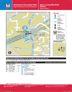


© Copyright 2026