
Safety of Loads on Vehicles CODE OF PRACTICE Third edition TSO: London
CODE OF PRACTICE
Safety of Loads on Vehicles
Third edition
TSO: London
Following the reorganisation of the government in May 2002, the responsibilities
of the former Department for Transport, Local Government and the Regions
(DTLR) in this area were transferred to the Department for Transport.
First published 1972
Second edition 1984
Third edition 2002
Department for Transport
Great Minster House
76 Marsham Street
London SW1P 4DR
Telephone 020 7944 8300
Web site www.dft.gov.uk
© Crown Copyright, 2002
ISBN 011 552547 5
Copyright in the typographical arrangement rests with the Crown.
This publication, excluding logos, may be reproduced free of charge in any format or medium
for research, private study or for internal circulation within an organisation. This is subject to it
being reproduced accurately and not used in a misleading context. The material must be
acknowledged as Crown copyright and the title of the publication specified.
For any other use of this material, please write to HMSO Licensing, St Clements House,
2-16 Colegate, Norwich NR3 1BQ Fax: 01603 723000 or e-mail: [email protected].
This document may also be viewed online via the Department’s web site.
Printed in Great Britain on material containing 75% post-consumer waste and 25% ECF pulp.
CONTENTS
GENERAL REQUIREMENTS
SECTION 1
9
Introduction
High Loads
Ferry Operations
Suggestions for Improvement
SECTION 2
11
12
13
14
Principles of Load Safety
SECTION 3
17
Choice of Vehicle and Arrangement of Loads
Choice of Vehicle
Arrangement of Loads
SECTION 4
17
18
21
Anchorage Points, Headboards and Internal Partitions
Headboards and Front Bulkheads
Exceptions
SECTION 5
Load Securing Equipment
21
24
27
SECTION 6
31
General Requirements for Securing Loads
Lashings
Sheeting
Netting
Blocking
Dunnage
Friction
Load Anchorage Points
32
34
36
37
38
38
39
ADDITIONAL REQUIREMENTS FOR SPECIFIC TYPES OF LOADS
SECTION 7
40
General Freight
Loading Arrangement on Vehicle
Restraint Equipment
Restraint Methods
Rolls, Drums or Cylindrical Loads
Boxes
Sacks
Loose Bricks
Mixed Loads
Containers Fabricated from Plastic Materials
Bales
40
41
41
41
44
44
44
45
45
46
SECTION 8
48
Metal Loads
General
Flat Sheet
Long Sections
Coils
Coils of Wide Sheet – Bore Horizontal
Coils of Wide Sheet – Bore Vertical
Coiled Rod and Bar
One Method of Securing Coiled Rod and Bar
Large Units and Castings
Scrap Metal
Scrap vehicles
Machinery and Tools
Steel for the Reinforcement of Concrete
Mixed Sheet Loads
SECTION 9
48
49
50
51
51
53
53
55
55
57
57
58
58
59
60
Timber Loads
Sawn Timber
Restraint Equipment
Round Timber
Whole Trees
60
61
61
64
SECTION 10
65
Loose Bulk Loads
65
SECTION 11
68
Pallets
Restraint Equipment
Restraining Methods
SECTION 12
70
70
72
Containers
ISO/BS Containers
Bulk Liquid Containers
Other Types of Container
Stowage of Goods in Containers
SECTION 13
72
73
73
75
76
Engineering Plant
Restraining Devices
Suggested Tie Down Schemes
SECTION 14
79
80
94
Carriage of Vehicles by ‘Piggy-back’
SECTION 15
97
Carriage of Dangerous Goods
SECTION 16
Curtain-Sided Vehicles
103
SECTION 17
106
Sheet Glass
Bulk Deliveries of Plate Glass
Carriage of Multi Size Plates up to Maximum Dimensions
Carriage of Small Quantities of Plate Glass, Frames etc.
SECTION 18
106
106
107
108
Vehicle Equipment
APPENDICES
APPENDIX A
110
Regulations concerning the safety of loads on vehicles
APPENDIX B
112
Regulations concerning ‘Dangerous Goods’ carried by road vehicles
APPENDIX C
117
Regulations concerning the transit of animals by road vehicles
APPENDIX D
118
Outline Risk Assessment
APPENDIX E
120
Terms and Definitions
APPENDIX F
British Standards quoted in this code
122
Acknowledgements
The Department for Transport wish to acknowledge the assistance of the following in the
preparation of this Code of Practice:
•
The Load Restraint Guide, compiled by the Federal Office of Road Safety and the National
Road Transport Commission and published by the Australian Government Publishing
Service. Commonwealth of Australia copyright reproduced by permission.
•
JCB Staffordshire.
•
Code of Practice Road Haulage of Round Timber published by the Forestry Contracting
Association Ltd.
•
Load Safety published by the National Association of Steel Stockholders.
SECTION 1
Introduction
1.1
The Road Traffic Act 1991 Introduced provisions into the Road Traffic Act 1988 making new
offences, applicable to the state of loads on vehicles. These provisions reflect the seriousness
with which the safety of loads on vehicles is now viewed.
1.2
Legal requirements and common sense require that all loads carried on vehicles are secured,
whatever the journey. This is to protect the people involved in loading, unloading and driving
the vehicle, together with other road users and pedestrians.
1.3
Both loading and unloading should be subject to a risk assessment, as required by the
Management of Health and Safety at Work Regulations 1999. A basic checklist for risk
assessment is given in Appendix D. Comprehensive advice on how to carry out risk
assessments can be obtained from the HSE.
1.4
Loading and unloading should be carried out by trained staff who are aware of the risks
involved. Drivers should also be aware of the additional risk of the load, or part of the load,
moving when the vehicle is being driven. This applies to all vehicles and to all types of load.
The driver is ultimately responsible for the load carried on their vehicle, whether or not they
were involved in the securing of the load.
1.5
This Code of Practice is not restricted only to the load being carried by the vehicle; it also
covers any equipment on the vehicle such as loader cranes, landing legs, tailgates etc. All of
these must be stowed and secured to manufacturer instructions so not to be a danger to other
road users and pedestrians.
9
Code of Practice: Safety of Loads on Vehicles
1.6
In the UK every year over 4000 successful prosecutions for unsafe loads are brought against
drivers and operators. Many other incidents involving the loss of loads or part loads go
unreported.
1.7
The Road Traffic Act 1991 states that:
a.
A person is also guilty of using a vehicle in a dangerous condition if he uses, or causes or
permits another to use, a motor vehicle or trailer on a road when the purpose for which it
is used or the weight position or distribution of its load, or the manner in which it is
secured is such that the use of the motor vehicle or trailer involves a danger of injury to
any person.
THE MAX PENALTY FOR THIS OFFENCE IF COMMITTED IN RESPECT OF A GOODS
VEHICLE IS A £5000 FINE, PLUS 3 PENALTY POINTS AND DISQUALIFICATION
b.
A person is to be regarded as driving dangerously if it would be obvious to a competent
and careful driver that driving the vehicle in its current state would be dangerous. In
determining the state of the vehicle for this purpose, regard may be had to anything
attached to or carried on or in it and to the manner in which it is attached or carried.
THE MAXIMUM PENALTY FOR DANGEROUS DRIVING IS 2 YEARS IMPRISONMENT.
THE MAXIMUM PENALTY FOR CAUSING DEATH BY DANGEROUS DRIVING IS 10
YEARS IMPRISONMENT.
10
1.8
If a load, or part of a load, falls into water and causes pollution, and the waters are controlled,
this is an offence under the Water Resources Act 1991. This could attract a maximum fine of
£20,000, together with the cost of cleaning up the affected water.
1.9
Although this document is primarily concerned with ensuring that loads are contained on
vehicles, you should be aware that there are legal obligations on operators and others to
ensure the safety of all persons involved in loading operations. These obligations expect safe
systems of work for loading, moving, unloading, sheeting and safe access onto vehicles.
Introduction
1.10
The principle legislation governing such matters is the Health and Safety at Work Act 1974 and
Regulation 13 of “The Workplace (Health, Safety and Welfare) Regulations 1992”. It is enforced
by the Health and Safety Executive and, at certain premises, by local authorities. There is an
Approved Code of Practice for the “The Workplace (Health, Safety and Welfare) Regulations
1992” which should be followed. Further information can be obtained from local offices of the
HSE (listed in telephone directories) or the HSE Infoline 08701 545500.
1.11
In this Code sections 1 to 6 outline the general requirements and basic principles of load
safety, and sections 7 to 18 provide advice. This advice is based on proven good practice, on
the satisfactory methods for securing the more common types of load.
1.12
The variety of loads, vehicles and operating conditions make it impossible to cover all the
circumstances likely to be encountered by drivers and operators. This Code must therefore
not be regarded as exhaustive or exclusive, but it does apply to all vehicles from the smallest
car derived van to the largest goods vehicle. Satisfactory securing methods not mentioned in
this code do exist, and others will be developed. However, the basic principles described in
this Code must be complied with, irrespective of the actual method used to secure the load.
1.13
In addition to the load safety methods described in this Code extra precautions are necessary
when dangerous goods such as toxic and corrosive chemicals and flammable substances are
carried on road vehicles. A list of the main Regulations and approved Codes of Practice
currently applicable to the carriage of these substances is given at Appendix B.
High Loads
1.14
Particular attention should be paid to the dangers of high loads that might have to pass under
bridges or other structures across roads. Every year several hundred bridges are hit by lorries
which are loaded too high or which are themselves too high to pass underneath. In some
cases this has resulted in the drivers of the vehicles and other people being killed or injured.
Any impact on a railway bridge has the potential to dislodge the rails, which can result in the
derailment of a train and the possibility of a serious railway accident.
11
Code of Practice: Safety of Loads on Vehicles
1.15
All vehicles with an overall travelling height above 3 metres must have the maximum height of
the vehicle in feet and inches displayed inside the cab so that it is clearly visible to the driver.
(Regulation 10 of The Road Vehicles (Construction and Use) Regulations 1986 as amended by
S.I. 1997 No 530)
1.16
Any vehicle fitted with high level equipment that is capable of exceeding a height of 3 metres
must be fitted with a visual warning device. This device must tell the driver if the equipment
has been left in the extended position. (Regulation 10A of The Road Vehicles (Construction and
Use) Regulations 1986 as amended by S.I. 1997 No 530)
Ferry Operations
12
1.17
When a vehicle is carried on a ship, as in roll-on, roll-off ferry operations, the vehicle and its
load will be subject to forces due to the rolling and pitching motions of the vessel. A restraint
system that is suitable for road use will not necessarily be adequate at sea.
1.18
The Department for Transport Marine Directorate’s Roll-on/Roll-off ships – Stowage and
Securing of Vehicles – Code of Practice, and the Department of Trade Merchant Shipping
Notice M849 or BS EN29367 gives some guidance on the securing of vehicles on ships and an
indication of the forces likely to be encountered at sea. Vehicle operators intending to use
ferries should ensure that their load restraint systems are capable of withstanding such forces.
1.19
The securing of the vehicle to the ship is also important and the vehicles should therefore be
fitted with lashing points that are of adequate strength to withstand the forces likely to be
encountered at sea. The lashing points should be easily accessible to deck crews and not
obstructed by fuel tanks, batteries etc. If necessary, advice on this latter point should be
sought from the ferry operators.
1.20
The maritime rules also apply to domestic open water crossings such as the UK mainland to
the various islands around it.
Introduction
Suggestions for Improvement
1.21
Inevitably, as a result of further experience and a continual development of load securing
systems, this Code of Practice will need to be periodically reviewed and amended.
Suggestions for improving or adding to is content are welcomed and should be sent to:
The Department for Transport
Vehicle Standards and Engineering Division
Zone 2/01, Great Minster House,
76 Marsham Street
LONDON SW1P 4DR
or
e-mail : [email protected]
13
SECTION 2
Principles of Load Safety
2.1
When a vehicle changes direction – cornering on roundabouts, overtaking etc., – friction is not
enough to stop unsecured cargo from moving. (See Figs 1 and 2) It is wrong to assume that
the weight of the load will keep it in position. In fact heavier loads are more likely to move
when the vehicle is in motion due to their kinetic energy being greater. Under heavy braking the
weight acting in a forward direction can be equal to that acting down on the vehicle.
Therefore, a load that is not restrained will not be secure.
Figure 1
14
Principles of Load Safety
Figure 2
2.2
The forces acting on the load during braking increase with the rate of deceleration and the
weight of the load. So, when the vehicle brakes the load will want to continue to move in its
original direction. The heavier the load and the harder you brake, the more the load will try to
move.
2.3
Friction alone cannot be relied upon to keep the load in place. When the vehicle is moving,
vertical movement caused by bumps will reduce any restraining force due to friction. This can
reduce to zero if the load even momentarily leaves the bed of the truck.
2.4
It requires much more force to stop a load that has started moving than it does to prevent
movement in the first place. This ‘battering ram’ effect increases rapidly with the increase in
15
Code of Practice: Safety of Loads on Vehicles
distance through which the load moves relative to the vehicle. It is essential therefore that the
load is restrained in such a way that movement of the load on the vehicle is prevented.
2.5
The basic principle upon which this Code of Practice is based is that the combined strength of
the load restraint system must be sufficient to withstand a force not less than the total weight
of the load forward, so as to prevent the load moving under severe braking, and half of the
weight of the load backwards and sideways (see Fig 3). Vertical movement may occur but this
should be overcome if the above conditions are met. This applies to all vehicles no matter
what the size, from small vans to the largest goods vehicles. These principles are based on
the maximum forces that are likely to be experienced during normal road use. Greater forces
may be encountered if the vehicle, for example, is involved in an accident. The principles
should therefore be regarded as minimum requirements.
Figure 3
16
SECTION 3
Choice of Vehicle and
Arrangement of Loads
Choice of Vehicle
3.1
It is the vehicle operator’s responsibility to provide suitable vehicles and securing equipment
for each load carried and to ensure that drivers and loading staff are competent and have
received sufficient instruction in its use. It is the driver’s duty to check and ensure that the
load is adequately secured at all times, not just at the start of the journey. This is especially
true after a violent manoeuvre such as heavy braking or swerving. It should be noted that with
certain bed materials such as aluminium, frictional forces helping to restrain the load could be
lower than expected, this is also true if the bed is wet.
3.2
The design and construction of the vehicle and its bodywork should be suitable for the loads
that it is likely to carry, particularly in terms of the characteristics and strengths of the materials
used. Anti corrosion treatments of load bearing components are highly desirable. When a
vehicle is to be carried on a ship, as in ferry operations, provision should be made for the extra
load restraint needed and for chassis anchorage points to secure the vehicle to the deck.
3.3
The maximum expected load on the vehicle floor should be known so that the floor itself and
the section and spacing of supporting crossbeams is sufficient. Strength calculations should
account not only for the load itself but also any extra forces due to the loading method, e.g.:
the use of forklift trucks on the floor during loading and unloading.
17
Code of Practice: Safety of Loads on Vehicles
3.4
The relationship between the vehicle’s wheelbase, body length and body overhang should be
carefully considered in relation to the composition of the loads to be carried especially if full
use is to be made of permitted maximum axle loads.
3.5
There are certain regulations governing the use of vehicles over 3m in height (see sections1.14
to 1.16) which must be followed.
3.6
To prevent vehicles grounding, on level crossings etc., regulations require that a certain
minimum ground clearance for trailers must be maintained (see Regulation 12 of the Road
Vehicles (Construction and Use) Regulations 1986). This is particularly important for low
loading trailers.
3.7
There are many factors in the choice of vehicle for carriage of dangerous goods. Flatbed
vehicles may be used provided that the goods are properly secured.(see section 6) Strong
cages fitted to vehicles will help prevent shedding of goods onto the carriageway. Before
dangerous goods are carried, the relevant publication in Appendix B should be consulted.
3.8
Where a vehicle is to carry a number of small loose items, e.g. a builder’s truck, the bodywork
should be higher than the load and be strong enough to prevent any part of the load from
breaking through. In addition, the risk of any part of the load being blown off or jumping out
due to bumps should also be considered.
Arrangement of Loads
3.9
3.10
18
Before a vehicle is loaded, it should be checked to ensure that its load platform, bodywork,
and anchorage points (and twist locks where fitted), are appropriate for the load, and are in a
sound and serviceable condition.
It is a legal requirement that the maximum permitted axle and gross weight limits are not
exceeded. Where a part of the load is to be picked up or removed in the course of a journey,
the effect on gross weight, individual axle weights and on the securing and stability of the load
must not be overlooked. Although removal of part of the load will reduce the gross vehicle
weight the change in weight distribution may cause individual axles to become overloaded,
Choice of Vehicle and Arrangement of Loads
(Commonly referred to as the diminishing load effect). This should be considered when
loading.
3.11
3.12
If practicable, and noting the requirements of 3.9, the load should be placed in contact with a
headboard. Where this is not practicable then additional means of securing must be used.
Possible methods include:
a.
Effectively moving the headboard rearwards, i.e. fitting an obstacle across the vehicle
platform which should be firmly attached to the chassis frame;
b.
Blocks, scotches, bolsters or wedges to prevent individual items of a load moving in any
direction. Care must be taken to ensure that these are adequately secured to the vehicle
platform;
c.
Additional lashing.
d.
In the case of a van, straps secured to the vehicle body should be used.
In order to achieve maximum vehicle stability the load should be placed so that the centre of
gravity is kept as low as practicable and near to the vehicle’s centre line.
This means that, where possible:
a.
The load should be spread to give an even weight distribution over the whole floor area;
b.
When a load is stacked the larger and heavier items should be placed at the bottom (see
Fig 4)
c.
The heavier items should be placed nearer to the centre line of the vehicle and the lighter
ones towards the sides.
d.
When a load is stacked the lower packages should be strong enough to support the
others when the vehicle is braking, cornering or accelerating;
19
Code of Practice: Safety of Loads on Vehicles
Figure 4
20
3.13
The weight of heavy loads of small dimensions should be distributed across the vehicle
platform by the use of load spreading devices. (e.g.. pallets, large wooden board etc.)
3.14
Normally the load should be arranged so that it does not obstruct the driver’s field of vision
including rear view through the driving mirrors. In the case of wide or long projecting loads or
where the load obscures obligatory lights, reflectors, rear markings or registration plates care
must be taken to ensure that the requirements of the Road Vehicles Lighting Regulations 1989
(SI No 1796) continue to be complied with.
3.15
A vehicle carrying a load or a vehicle fitted with a special appliance or apparatus that
overhangs the load area may require special markings. If there is a rearward projection
between 1m and 2m the overhang must be made clearly visible to other road users. If there is
a forward or rearward projection exceeding 2m or there is a projection on either side of the
vehicle of more than 305mm or the overall width of a vehicle or any lateral (sideways)
projection exceeds 2.9m then Regulation 82 of The Road Vehicle (Construction and Use)
Regulations 1986 must be complied with. It should be noted that in some circumstances it will
be necessary to notify the police before the vehicle can run on public roads.
SECTION 4
Anchorage points, headboards
and internal partitions
Anchorage Points
4.1
It is common practice to use the rope hooks found on most platform vehicles, welded or
bolted to the underside of the side rail or outriggers, as the anchor points for the load restraint
systems. Rope hooks should not be used to anchor loads. Rope hooks are not subject to
constructional standards, and so they vary in strength, size and material content and are rarely
designed to withstand forces exceeding about 1-1.5 tonnes. Many fall far short of this
strength being so weak that they can be distorted by applying a ratchet buckle to tighten a
webbing strap. For this reason it is desirable to equip vehicles, particularly those with platform
bodies, with dedicated load anchorage points. These should be designed and integrated into
the structure so that the forces imposed on them are transmitted to the main chassis frame of
the vehicle. (See figs 5 and 6.) Lashing points should comply with British Standard BS EN
12640:2001.
4.2
Load anchorage points should be rated at capacities of 0.5 tonne, 1.0 tonne or 2.0 tonne and
upward. The capacity of each anchorage point should be indicated on the vehicle and the
vehicle manufacturer or bodybuilder should provide information on the capacity of each
anchorage point. The design and construction must allow a safety factor of twice the specified
capacity acting in any direction through which the lashing can be attached.
4.3
Anchorage points should be so designed that they transmit the forces they receive into the
main structure of the vehicle. The design should be such that there is minimal movement of an
21
Code of Practice: Safety of Loads on Vehicles
anchorage point when loaded by a restraint, as any movement will seriously reduce the
effectiveness of the restraint. The anchorage points must be compatible with the type of
securing equipment likely to be used. It is recommended that the attachments meet the
relevant British Standards, e.g. eye bolts to BS 4278 and shackles to BS 3551.
4.4
Anchorage points should be firmly attached either directly to the chassis or to a metal
crosspiece or outrigger. Anchorage points that are secured only to wooden members are
unlikely to provide the restraint required. The fitting of additional anchorage points to existing
vehicles must in no way weaken the chassis or body structure. In particular, the drilling of
holes in the chassis and welding to it should not be considered without the approval of the
original manufacturer. If the anchorage points are fixed at or in the loading area they should
not project above the horizontal level of the loading area in their position of rest. The size of
any recesses should be no larger than is necessary for the particular anchorage used.
4.5
Sufficient load anchorage points should be provided. The sum of the capacity of the
anchorage points on both sides of the vehicle (assuming that they are evenly distributed)
should not be less than the maximum rated load of the vehicle. There should be a minimum of
3 on each side. Thus a 3.0 tonne rated load would require at least three per side each of 0.5
tonne capacity. In the case of higher rated loads the number of anchorage points and their
capacity will also depend on whether the vehicle is purpose built for a particular type of trade
or is to be engaged in general haulage operations where the size and weight of individual items
may vary.
For example, an operator of a 20 tonne rated load vehicle used exclusively for a particular
commodity might need to choose between specifying 40 x 0.5 tonne points, 20 x 1.0 tonne
points, or 10 x 2.0 tonne points depending on the character of the load. On the other hand, the
general haulier with a similar vehicle used for miscellaneous loads would in all probability need
six or more 2.0 tonne points plus enough 1.0 tonne or 0.5 tonne points to make up at least the
required 20 tonne of restraint. The precise pattern would depend upon the types of load to be
carried.
4.6
22
The number of anchorage points actually used on a particular journey will depend on the
weight and dimensions of the load being carried and its location on the platform in relation to
the headboard or other additional means of restraint.
Anchorage points, headboards and internal partitions
Figure 5
Figure 6
23
Code of Practice: Safety of Loads on Vehicles
The table below gives some suggested values but in some cases additional restraint by the
headboard or other means may be required.
a. 2 Axle Vehicles (Flats/Pickups/Drop-sided)
Body Length
Minimum number of 0.5 tonne anchorage points
Minimum – 3.6m (12ft)
3.6m – 4.9m (16ft)
4.9m – 6.1m (20ft)
6.1m – 7.3m (24ft)
6
8
10
12
8
10
12
14
10
12
14
16
12
16
18
20
–
18
20
24
0-2
2-4
4-6
6-8
8+
Payload (Tonnes)
b. 3 to 4 Axle Vehicles
Body Length
Minimum number of 0.5 tonne anchorage points
Minimum – 5.5m (18ft)
5.5m – 7.3m (24ft)
7.3m – and above
14
18
20
16
20
22
18
22
24
20
24
28
22
26
30
0-10
10-12
12-16
16-20
20+
Payload (Tonnes)
For vehicles carrying heavy concentrated loads on a regular basis it is preferable to have purpose
built heavy duty anchorage points let into decking/side raves at a joined cross member
c. Trailers
Trailers should also conform to the above weight/length dimensions for securing points.
Headboards and Front Bulkheads
24
4.7
A headboard, when fitted, can be treated as part of the load restraint system. [There are some
exceptions, which are listed at the end of this section.]
4.8
A headboard should be capable of withstanding a horizontal force uniformly distributed over its
vertical area equal to at least half the rated payload of the vehicle. IMPORTANT see Section 7
paragraph 1 for factors that reduce effectiveness. The design must be such that the whole
body and vehicle structure will withstand the forces imposed on it when the headboard is
loaded as described above.
Anchorage points, headboards and internal partitions
4.9
The headboard width should be equal to the width of the loading platform unless the type of
load permits a narrower headboard. It should however not be less than the width of the cab.
4.10
The headboard height should be sufficient to obstruct forward movement of the type of load
that the vehicle is designed to carry unless adequate load restraint is provided by other means.
4.11
The headboard should not have apertures large enough to allow penetration by any part of the
load. Large apertures to aid the driver’s vision should be covered with a steel mesh or similar
material that is equal in strength to the rest of the headboard.
4.12
For loads such as metal bars, beams, girders, sheet metal etc. which could penetrate the cab
in the event of failure of the securing devices, the headboard must be adequately reinforced to
resist damage from individual elements of the load.
4.13
For the maximum benefit to be derived from a headboard it is essential that the load is in
contact with it. If a space is left so that the load can move forwards before reaching the
headboard then its restraining capacity will be greatly reduced. Packing blocks can help,
provided that they are suitably restrained themselves.
4.14
Headboards should be examined frequently for damage. Particular attention should be given
to timber panels or boards and to the mounting point of the headboard to the chassis.
Damaged headboards should not be used for restraint purposes.
4.15
Where ever possible, cargo should be carried separately from passengers. In the case of
closed vans where the cab is an integral part of the body, a bulkhead must be fitted, between
the load compartment and the cab. Such a bulkhead should afford adequate protection to cab
personnel and should be designed to resist a uniformly distributed horizontal force of at least
half the weight of the load.
4.16
It should be noted that when an estate car is used to transport goods, these too should have a
bulkhead fitted to protect front seat personnel. If a bulkhead is not fitted then the load must be
suitably restrained to prevent any forward movement.
25
Code of Practice: Safety of Loads on Vehicles
4.17
Vehicles are sometimes divided by internal partitions into a number of compartments each of
which is self-sufficient in terms of load restraint. The headboard or internal partition should be
designed to resist a uniformly distributed horizontal force of at least half the rated load for that
compartment.
4.18
Exceptions (see paragraph 4.7)
4.19
26
a.
Bodies designed specifically for loads that are to be restrained by means other than the
headboard. e.g. refrigerated vans. These vehicles should carry a manufacturer’s plate
clearly stating the types of load for which they are intended and the method of load
restraint to be used.
b.
Trestle type headboards or bolsters for supporting long loads should carry a
manufacturer’s plate clearly stating the rated load capacity both vertically and horizontally
because the forces will be determined by the type of load carried. e.g. a bolster to support
a crane jib will not require the same horizontal strength as a bolster to support one end of
a steel girder.
c.
Vehicles used for the carriage of carcass meat should be equipped with rails and sliding
hooks and be adequately lit. The rails should be fitted with fixed hinged ‘stops’ at 1 to
1.5m intervals to prevent the surging or sliding of carcasses due to motion of the vehicle
or brake application. When loading the vehicle the carcasses should be distributed evenly
on all rails and the stops applied. If part off-loading takes place the remaining load should
be re-distributed evenly and the ‘stops’ re-applied. At all times the floor of the vehicle
should be kept clear of blood and other slippery matter.
In addition to the load safety methods described in this Code extra provisions are necessary
when animals are carried on road vehicles. A list of the main regulations and approved Codes
of Practice currently applicable to the carriage of animals is given at Appendix C.
SECTION 5
Load securing equipment
5.1
The selection of the best means of securing a load to a vehicle will depend on the type and
composition of the load to be carried. Operators should equip themselves with the correct
securing equipment for the types of load carried and where general cargoes are carried various
types should be available. Clamps, special bolts, steel wire ropes, chains, webbing harnesses,
sheets, nets, ropes and shoring bars are all suitable devices for use in load restraint but it is
essential to ensure that they are strong enough for the weight of loads carried.
5.2
All equipment used for securing loads should be regularly inspected for wear or damage.
Inspection arrangements should be in accordance with the manufacturers instructions. Special
attention should be paid to webbing and rope to ensure that there is no visible deterioration
due to constant use, such as fraying of the strands. They should also be inspected to ensure
that they have not been cut or damaged in any other way through misuse. If there is any
doubt as to whether repairs are required, reference should be made to the manufacturer or
suppliers of the lashing.
5.3
Steel wire rope made up into special straps or slings is suitable for securing a load when used
in conjunction with other devices such as shackles and thimbles. The strength of steel wire
rope will depend on the grade of the steel used, the number of strands, the number of wires in
each strand, the diameter of the rope and the method of construction. Wire ropes must have a
safe working load compatible with the requirements of the load being carried.
Recommendations for the minimum breaking load of various sizes and types of wire rope are
contained in BS 302, BS 1290 gives safe working loads for wire rope slings, and BS 6210 is a
Code of Practice for wire rope slings. Wire ropes having a diameter of less than 8mm will not
be suitable for load restraint purposes. Wire ropes should be free from rust and must not be
27
Code of Practice: Safety of Loads on Vehicles
used if they show evidence of weakening such as broken wires or strands. Other coupling
equipment used with wire rope must be of corresponding quality and strength.
Sharp bends will reduce the effective strength of wire rope.
5.4
Chains are suitable for lashing loads when used in a similar manner to steel wire ropes. Three
properties determine the strength of a chain: the length of its links, the thickness of its links
and the quality of the metal used. The longer the link the more susceptible the chain is to
damage – long links can easily be deformed if they are tensioned over a corner. The chain
used should be compatible with the requirements of the load carried. Where necessary strong
packing or bevelled sections should be used on corners or sharp edges which prevent damage
to the ropes and chains and also increase the radius around which they bend, thus increasing
their effective strength.
Recommendations for the safe working of various sizes of steel chain are contained in BS
1663, BS 4942, BS 6304 and BS 6968 (ISO 3056). The use of iron or split link chain is not
recommended. Any joining links in chains should always be inspected before use. Chains
should only be used in conjunction with suitable tensioners and turnbuckles with a safe
working load that is compatible with that of the chain.
5.5
Webbing assemblies are suitable for securing many types of load. They usually consist of a
webbing strap with some form of end fittings and incorporate a tensioning device. It is
recommended that assemblies manufactured to BS 5759 are used. These are marked with a
Rated Assembly Strength (RAS) which should never be exceeded. Webbing made from
polyester, polyamide or polypropylene may be used. Polyester loses a little strength when wet,
is highly resistant to moderate strength acid but can be damaged by alkali. Polyamide may
lose up to 15% in strength when wet, is highly resistant to alkalis but can be damaged by
moderate strength acids. Polypropylene is useful where chemical resistance is a requirement.
Before use, care should be taken to ensure that the metal components of the harness are not
corroded or damaged, that the webbing is not cut or frayed and that all stitching is sound. If
damage is found, advice should be sought from the manufacturers to check if repairs are
possible.
28
Load securing equipment
5.6
Nets securing or retaining some types of load may be constructed from webbing straps or
ropes of either natural or man-made fibres or steel wire. Webbing nets are generally used as
barriers to divide the load space into compartments. Rope or cord nets may be used to
secure loads either to pallets or direct to the vehicle as the primary restraint system.
Lighter nets can be used to cover open bodied vehicles and skips when the type of load
makes it unnecessary to use a sheet. Care should be taken to ensure that the metal
components of nets do not become corroded or damaged, that the webbing is not cut and
that all stitching is sound. Rope and cord nets should be checked for cuts or other damage to
the fibres. If necessary, repairs should be carried out by a competent person before the net is
used. The mesh size of the net must be smaller than the smallest part of the load. It is
recommended that all nets, both light and heavy should comply with BS 6451.
5.7
Rope used for securing loads should preferably be manufactured from polypropylene,
polyester, sisal or manila. Polyamide (nylon) ropes are not suitable, as they tend to stretch
under load. Ropes should be of 3-strand construction and must have a minimum nominal
diameter of at least 10mm. The ends of the rope should be spliced or otherwise treated to
prevent fraying. Rope should be selected having regard to the maximum loading to be
imposed in each lashing and it is recommended that ropes manufactured to BS EN699:1995,
697:1995 or 698:1995 should be used. The manufacturer on an attached label or sleeve
should indicate the maximum rated load for these ropes. Knots and sharp bends will reduce
the effective strength of rope and the strength of sisal or manila rope is also likely to be
reduced by water saturation. Wet ropes should always be allowed to dry naturally.
5.8
Purpose made clamps are suitable for securing loads which are fitted with lifting pockets,
brackets or other specially designed attachments. In most cases it will be necessary to
reinforce the deck of the vehicle in the vicinity of the clamp position. The design of the clamp
and reinforcement should be carried out in accordance with the recommendation of the vehicle
manufacturer. A minimum of four clamps should be used and any three of these must be
strong enough to restrain the load if one clamp fails to function correctly.
5.9
ISO freight containers are secured to vehicles by means of special container locks commonly
known as twist locks. (ISO 1161/BS 3951 covers the specification for corner fittings for series
1 freight containers) In most cases twist locks will be fitted to the vehicle during manufacture
29
Code of Practice: Safety of Loads on Vehicles
but where they are fitted at a later date then modifications to the chassis/structure should be
carried out in accordance with the recommendations of the vehicle manufacturer. Twist locks
should be inspected regularly for wear, damage and correct operation. Locking devices, which
are intended to prevent the operating levers from moving during transit, should be given
special attention. The “Freight Containers (Safety Convention) Regulations 194” deal with the
examination and plating of freight containers in general. A minimum of four twist locks should
be provided for each container carried.
5.10
30
Sheets are of two types;
a.
Tarpaulins, which provide weather protection only and should not be used as part of a
restraint system.
b.
Purpose made load sheets incorporating webbing straps are satisfactory up to their rated
load capacity provided the straps are secured to body attachments of equivalent strength.
5.11
Sleeves and corner protectors should be used to prevent damage to both the load and the
restraint equipment where it passes over a sharp corner.
5.12
Banding (steel or plastic), commonly used for binding loads together, is not an adequate
method for securing loads to vehicles. The wide range of banding available makes it difficult
to ensure that the type to be used has sufficient strength for the task and there is a real risk
that it will work loose during the journey. If this happens the driver has no means of retightening it.
SECTION 6
General requirements for
securing loads
6.1
The total load restraint system will generally consist of a combination of:
a.
lashings secured to anchorage points attached to the vehicle chassis, which includes
cross bearers, outriggers etc.;
b.
bulking arrangements including headboards, bulkheads, spigots, transverse beams,
shoring bars etc. which are securely attached to the vehicle;
c.
friction between the load and the vehicle platform.
In most circumstances it would be appropriate to obtain the majority of the total restraint
required from (a), and the remaining part from (b). Benefits accrued from (c) should be
regarded as a bonus. Vehicles using fabric sides, for example curtain-siders, will normally
require additional internal restraints. (See section 16).
6.2
Headboards, sideboards and tailboards fitted to vehicles, if adequately constructed, may
provide some restraint to movement of the load. Light loads may be carried without additional
restraint provided that the height of the load is less than the height of the boards, and that
there is no risk of the load moving and breaking through any of the boards or bouncing off the
vehicle. In any instance where the load exceeds the height of any of the boards some form of
lashing must be used.
31
Code of Practice: Safety of Loads on Vehicles
Figure 7
32
6.3
On platform vehicles some form of load restraint will always be required.
6.4
The load must be packed tightly before applying the restraints, which should be arranged so
that no part can accidentally be released by vibration or road shocks while the vehicle is in
motion.
6.5
The restraints should be arranged so that failure or slackening of a single component does not
render the remainder of the system ineffective.
6.6
All items of loose equipment not in use (sheets, ropes, dunnage etc.) and loose surplus
equipment in service (rope ends etc.) must be securely restrained at all times.
6.7
Always check that cargo doors are locked and that locking mechanisms are in good condition.
The load must be checked for security and the lashings tested for adequate tension after the
vehicle has travelled a few miles and again at intervals throughout the journey. Weather
conditions can affect the tension of lashings, which may lead to loss of security and damage to
the load if not correctly re-tensioned.
General requirements for securing loads
Figure 8
6.8
In order to obtain the maximum efficiency from every part of the restraint system it is essential
that the requirements described in the following paragraphs are met.
Lashings
6.9
The lashings and fastening devices (ropes, webbing, chains, cables, clamps etc.) should be in
sound condition and must be capable of withstanding all normal forces. To avoid movement
of the load, lashings must be properly tensioned at all times using a tensioning device
specified by the manufacturer of the lashing. Never over tension lashings by the use of levers.
6.10
It is most important that lashings which provide forward restraint are as near to the horizontal
as possible and never at an angle of more than 60˚ this is because the effort required to
restrain the load increases sharply as the lashings approach the vertical position (see Fig 7).
Where lashings are at an angle of 60˚ the total lashing force required to prevent a mass from
moving forwards is 2 x cargo mass if there is no other means of restraint (e.g. headboard) and
1 x cargo mass sideways or rearwards. It has already been stated that the restraints should
33
Code of Practice: Safety of Loads on Vehicles
not be at an angle greater than 60˚ as the lashing force is greatly increased above this angle.
e.g. if the lashing was 85˚ to the horizontal, the force required to prevent the mass moving
forward would need to be 11.5 x cargo mass.
There should be at least one lashing every 1.5m along the length of the load.
6.11
Lashings must be protected against abrasion and or cutting by the use of corner protectors or
protective sleeves.
6.12
A load positioned to one side of the vehicle will, if the restraint is looped over it, require a
longer restraint than if the load was mounted centrally. (See Figure 8). This means that
even if the restraint is initially tight, any movement of the offset load towards the centre line of
the body platform will result in a loss of tension in the restraint leaving the load insecure. If it is
necessary to carry off-centre loads then it should be positively restrained by either attaching
the restraints to the side of the load or by routing the restraints around the load longitudinally.
Sheeting
6.13
34
After the sheeting and roping is completed ensure that all loose rope ends have been tied up
and that the lights, reflectors, numberplates and rear markings etc. have not been obscured by
any part of the sheet.
a.
Where more than one sheet is required to cover and protect the load the rearmost sheet is
positioned first. This ensures that overlaps do not face forward allowing wind and rain
etc. to get between sheets (see Fig 9). The same principle should be applied to folds at
the front or on the sides of the vehicle so that wind pressure will tend to close any gaps or
folds in the sheet rather than open them.
b.
Having positioned the sheets on the load ensuring that all parts are covered and that
sheets are equal on each side, secure the front of the rear sheet followed by the rear of
the front sheet. Do not over tighten or sheets will be drawn up to expose the load at the
rear or at the front.
General requirements for securing loads
Figure 9
Figure 10
35
Code of Practice: Safety of Loads on Vehicles
c.
There should be no loose flaps or tears in the sheet, which might cause danger to other
road users when the vehicle is moving (see Fig 10). Care should be taken to avoid striking
any person in the vicinity when throwing lashings over loads during the securing
operation, any sheeting aids or any structural features of the workplace that are provided
to assist in such operations should be made full use of.
d.
The next stage is to secure the front of the sheet. Step 1, draw in surplus sheet from
sides, cross over front and secure.
Step 2, draw down over crossovers the remaining surplus sheet to form a full width flat
front flap (see Fig 11).
e.
Having secured front sheet, secure the sides of the rear sheet to the rearmost corners.
f.
Rear of the load should then be sheeted and folded (see Fig 12).
Figure 11
36
General requirements for securing loads
Figure 12
Netting
6.14
Nets and their attachments (lashing ropes, border ropes, hooks etc.) should be in sound
condition, the British Standard specification for fibre rope nets is BS 6756:1986.
6.15
The maximum rated loading of the net should never be exceeded.
6.16
Nets must be properly tensioned using a tensioning device specified by the net manufacturer.
Never over tension a net by the use of a lever or other unauthorised device.
6.17
The mesh size should always be less than the smallest item the net is expected to retain;
except that this will not always apply to nets used to retain loose bulk loads because these are
not subject to the same loading conditions.
6.18
Protection against abrasion and/or cutting should be provided by the use of corner protectors
or corner sleeves.
37
Code of Practice: Safety of Loads on Vehicles
Blocking
6.19
Chocks, wedges and scotches may be used to prevent individual items of a load from moving
in any horizontal direction. Care must be taken to ensure that these are stout enough and are
adequately secured to the vehicle platform.
Dunnage
6.20
It is preferable for all the individual units or packages comprising a load to be packed closely
together before any restraint lashings are applied. If this is not possible then some form of
packing, commonly known as dunnage, must be used to fill any gaps that exist between parts
of the load or between the load and the vehicle sides.
6.21
The use of loose dunnage between the load and the platform should be avoided wherever
possible but where it must be used to support an awkwardly shaped load it should be secured
to prevent movement during the journey.
6.22
Care must be taken not to damage the load by using unsuitable dunnage and therefore the
type of load being carried will govern the choice of material to some extent. A number of
materials are suitable for use as dunnage, the most common being timber, folded cardboard,
hardboard, high-density foam, and air bags. Timber dunnage should be of uniform thickness
and maximum possible width. The minimum width should, where practicable, be twice the
thickness and it is always preferable to use only a single layer.
Friction
6.23
38
Friction between the load and the platform should be regarded as a bonus and should not be
taken into account when calculating the lashing force required.
General requirements for securing loads
6.24
A slippery platform surface is always dangerous and the aim should be to obtain the maximum
advantage from the frictional restraint by keeping both the base of the load and the platform
surface as clean, dry and free from grease as possible.
Load Anchorage Points
6.25
Lashings used to restrain the load must always be attached to anchorage points that have
sufficient strength to absorb the expected loading. Any restraint system is only as strong as
its weakest component.
6.26
Anchorage points should themselves be firmly attached either directly to the chassis or to a
metal crosspiece or outrigger.
6.27
Anchorage points, which are secured to wooden members only, are not likely to be strong
enough to provide the restraint required.
6.28
Rope hooks should only be used for roping, and then only for relatively light loads. They
should not be used in place of the correct anchorage points.
6.29
The rated load capacity of the anchorage point must never be exceeded.
39
SECTION 7
General Freight
7.1
In view of the wide diversity of general loads it is not possible to suggest loading methods for
all the types of load likely to be encountered. However, the basic precautions outlined in
section 6 will always be applicable. Vehicles equipped with headboards, tailboards or
sideboards, or van bodies will provide some restraint. Additional load restraint will be required
under any of the following conditions:
a.
If there is a risk that the load may break through the walls, sideboards or tailboard of the
vehicle;
b.
When the load is higher than the headboard, sideboards or tailboard of the vehicle;
c.
If the load is liable to be damaged should it move during transit.
d.
If there is a risk of the load being blown off, or bouncing out of the vehicle.
Loading Arrangement on Vehicle
7.2
40
Two essential requirements must be satisfied when loading vehicles. These are that the load
must be distributed so that
a.
The maximum permitted gross vehicle weight and axle weights are not exceeded, and
b.
The load centre of gravity is kept as low as possible to achieve maximum stability when
the vehicle is braked, or accelerated or changes direction.
General Freight
7.3
For maximum stability, the items comprising of the total load should be evenly spread to
achieve minimum height and be arranged to form a uniform whole so that no excessive stress
is applied to whatever restraining devices are used. Where a part of the load is to be picked
up or removed during the course of a journey the effect on gross vehicle weight, individual axle
weights and on the securing and stability of the load then being carried must be considered
during the initial loading and subsequent unloading. For example, removing a part of the load
from behind the rear axle of a vehicle or trailer will reduce the gross vehicle weight, but it will
increase the weight on the front axles and may cause individual axles to exceed their plated
weights.
Restraint Equipment
7.4
Various types of equipment can be used for restraining general freight loads. These include
rope, chains, steel wire rope, webbing, strapping or netting. For the securing of loads inside
van bodies and similar load containers, specially designed shoring piles used in conjunction
with the appropriate securing fixtures on the vehicle are suitable. Purpose built restraining
devices should only be used for the application, and in the manner approved by their
manufacturers.
Restraint Methods
7.5
Loading methods for certain general categories of loads are outlined in the following
paragraphs.
41
Code of Practice: Safety of Loads on Vehicles
Rolls, Drums or Cylindrical Loads
7.6
Rolls or cylindrical items should ideally be placed with their axis across the vehicle so that the
rolling tendency will be to the front or rear. In many circumstances additional dunnage,
stopping blocks or wedges should be used, particularly on rounded sections where there is a
tendency for roll to take place. This dunnage should be regarded as supplementary to the
webbing restraints whose total strength should not be reduced because of its use. When
securing cylindrical items practical consideration should be given to how the load is to be
unloaded in a safe and controlled manner.
Figure 13
On the left is a method of creating downward force on large tubular loads by using dunnage.
The method used on the right creates the necessary downforce on smaller tubes by using
folded sheet or other padding.
7.7
42
Figure 14 shows a load of paper or cardboard rolls. When the bottom layer has been
positioned and secured on the platform and the first roll of the second layer (‘A’ in figure 14)
has been loaded, the overlashings are laid over ‘A’ and across the top of the bottom layer. No
tension is applied to the lashings at this stage. The remaining rolls can now be loaded after
which the ‘between-layers’ lashings are secured to the rear of the vehicle and ‘tap-over’
lashings applied. A tarpaulin sheet is usually added to provide weather protection (see figure
15). Between layers lashings may be omitted when loading metal or concrete pipes since their
weight and abrasive nature would cause excessive damage. It may be the case that these
lashings have to be omitted to prevent damage to the load. Such omissions must be made
good by additional top lashings and chocks and cradles.
General Freight
Figure 14
Figure 15
7.8
If the length of the cylinders is less than twice their diameter they should be placed on end
unless the consignor gives instructions to the contrary. If the length is greater than twice the
diameter, but less than the width of the vehicle, they must be positioned so as to roll forwards.
Each row must contact the one in front, and rear ones must be chocked to prevent rolling
backwards.
7.9
If the drums, rolls etc. are standing on end, lashings must be used to prevent lateral (sideways)
movement and further cross lashings must be applied. If on their sides, they should have at
least one cross lashing for each item. If there is more than one layer, the rearmost roll or drum
must be restrained by lashing or blocking against rearward motion.
43
Code of Practice: Safety of Loads on Vehicles
Boxes
7.10
Boxes must be loaded so that they are prevented from moving in any direction. They should
interlock if possible, and be loaded to a uniform height. There must be at least one lashing for
each row of boxes across the vehicle and any box which is above the general height of the
load must have at least one cross lashing, more depending on weight and size.
Sacks
7.11
Sealed sacks should be laid on their sides with alternate layers in opposite directions. In any
event no more than two successive layers should be in the same direction. The load should
be of uniform height when possible. There must be at least one cross lashing for each sack
length. Loads of sacks should be sheeted if possible.
7.12
Open sacks, for example those used for coal delivery, should be loaded and secured in a
similar way with cross lashings for each layer. The total load should also be sheeted to prevent
loose materials being lost from the vehicle.
7.13
With certain loads the use of tensioners may be desirable. This is particularly true of loads that
tend to settle around the lashings.
7.14
Empty sacks, which can fall from a vehicle when in motion, can be extremely hazardous and
these must therefore be securely restrained to the vehicle’s platform.
Loose Bricks
7.15
44
Both the bulk mass and individual items must be restrained. The load height should not
exceed the height of the surrounding body. Purpose made restraint systems may be used
provided their strength is sufficient for the load being restrained.
General Freight
Mixed Loads
7.16
When a load is composed of different items each part of the load must be secured in a manner
suitable to a load of its type. This applies mainly to cross lashings. The longitudinal lashings
must be adequate for the total weight of the load, and separators must be used so that no part
of the load can move forward independently. The following procedures should be followed
when applicable.
a.
Where mixed loads involve heavy solid articles and light crushable boxes the heavier
articles should provide the base and rear part (‘A’ in figure 16) and the light portion be
loaded on top and to the front (‘B’ in figure 16).
b.
When loading different sizes of container small items should be central, with the larger
items forming the outer walls of the load (see figure 17). Avoid as far as possible
obstructions or projections beyond the vehicle sides.
c.
Keep irregular shaped items for the upper part of the load where it is not possible to place
them centrally within the load.
d.
Special precautions may have to be taken when dangerous substances are included in a
load. These include segregation of substances which may interact together (see section
15.6), protection from rain and careful handling and stowage to reduce the risk of damage
to vulnerable containers. The packages should be loaded in such a manner as to enable
the labels to be easily read.
Containers Fabricated from Plastic Materials
7.17
Over recent years there has been a significant increase in the use of drums, kegs, boxes,
crates and bottles of assorted shapes and sizes fabricated from plastics instead of metal.
Plastic surfaces particularly when damp are very slippery and care must be taken in loading,
securing and sheeting. It is particularly important where the carriage of dangerous substances
45
Code of Practice: Safety of Loads on Vehicles
Figure 16
Figure 17
is involved, all appropriate precautions should be taken to maintain the stability of the
consignment on the vehicle during transit.
Bales
7.18
46
If the material that is to be transported is in bales (hay, cloth etc.) then the suggested loading
pattern is as follows.
General Freight
Figure 18
a.
The first two tiers are loaded transversely and the centre five bales secured to the vehicle
b.
The third tier is loaded longitudinally and each bale secured individually to the vehicle
c.
If a forth tier is added it should comprise of no more than two rows of bales, and these
too should be loaded longitudinally and the front and rear bales secured to the vehicle.
d.
The whole load should then be covered with a sheet.
47
SECTION 8
Metal Loads
General
8.1
Small relatively heavy items, such as small castings, if not palletised or caged, should be
securely restrained and carried on sided vehicles. The headboard, sideboards, and tailboard
must be higher than the load and must be strong enough to withstand the forces generated by
the vehicle’s motion.
8.2
Careful attention should be paid to points where lashings pass over corners of the load to
ensure that the load is not damaged by chain links etc. or that the lashings are damaged by
sharp edges. Corner protectors and sleeves should be used whenever necessary.
8.3
The friction between individual items in a load will generally be low, particularly if the metal is
oiled, and should therefore be disregarded when assessing the total load restraint required.
The friction between load and vehicle platform will also be considerably reduced if either is wet
or greasy. The only exception to this rule is when concrete reinforcing weld mesh is carried. In
this case there is significant friction between bundles of the mesh loaded on top of each other.
8.4
A large mass can be restrained more effectively than a number of small items and therefore
whenever possible loads should be aggregated into the largest or heaviest unit feasible. This
will be controlled to some extent by the facilities available at the point of unloading.
8.5
Metal loads can take various forms but they can be broadly divided into 9 categories:
a.
48
Flat sheet
Metal Loads
b.
Long sections
c.
Coils
d.
Large units and castings
e.
Scrap metal
f.
Scrap vehicles
g.
Machinery and tools
h.
Steel for the Reinforcement of Concrete
i.
Combination of the above i.e. mixed loads.
Flat Sheet
8.6
When mixed sizes of sheet or plate are being carried, the smallest should normally be loaded
on top and at the front of the vehicle so that they cannot slide forward, where large sheets are
carried marker boards may be required, see section 3.15.
8.7
Oiled flat sheet should be bundled and packed in steel sheets, which form a box around the
bundle, commonly known as trumpeting.
8.8
It is essential that the lashings are always in firm contact with the top surface of the load. If
the load is level with, or lower than, the side raves of the vehicle then the lashings will be
ineffective. In these instances the load should be raised off the floor by the use of timber
packing.
8.9
Flat sheet is sometimes loaded onto pallets in which case the advice given in Section 11
should also be followed.
49
Long Sections
50
8.10
This type of load will generally be carried along the length of the vehicle and can pose
particular problems since a section can easily penetrate a headboard or driver’s cab if it is
allowed to move. It is essential therefore that the vehicle is loaded in such a way that the
complete load forms a unit and no single item can move independently.
8.11
The load will always need to be restrained by lashings, preferably chains or webbing. If
possible these should be attached to the vehicle by means of load anchorage points as
described in Section 5. When the vehicle is not fitted with such anchorage points it is
common practice to pass the lashings around the vehicle to form a continuous loop which is
not physically attached to the vehicle in any way. If this method is used the utmost care
should be taken to avoid damage to the chassis frame or other vehicle components. A
minimum of 4 lashings must be used. It is essential to realise that, although this form of
lashing might provide reasonable sideways restraint, forward restraint is provided only by
friction and this will not be adequate to restrain the load during heavy braking and some
additional means of forward restraint will be necessary. Because there is no ‘give’ in metal
products it will often be an advantage to place a piece of timber at a convenient point between
the lashings and the load. This will help to maintain the tension in the lashing.
8.12
If the load is stacked it should be kept as low as possible with the heavier items at the bottom
and the lighter ones on top. No layer should be bigger than the one underneath it.
8.13
To prevent forward movement the load should be placed in contact with a headboard or
otherwise be securely restrained. To achieve an even weight distribution long loads are
sometimes carried on a bolster type headboard so that the load projects forward over the
driver’s cab. In this case individual items should be combined into the largest or heaviest unit
feasible and forward restraint provided by lashing the entire load securely to the bolster.
Additional restraints will need to be provided at the rear.
8.14
If stanchions or side pins, either attached to the vehicle or to specially made bolsters, are used
to prevent sideways movement they should extend to the height of the load. Sideboards
Metal Loads
should not be relied upon to provide more than a minimum of sideways restraint. Long product
loads consisting of tubes and pipes tend to spread sideways causing the load to belly
outwards. Stanchions or side pins reaching the height of the load are recommended both to
provide the necessary additional sideways restraint but also to facilitate the safe unloading of
the payload.
Stanchions, side pins and their locating devices should be of sufficient strength or safe
working loads to ensure that they can provide sufficient sideways restraint should the
lashings fail.
Coils
8.15
To avoid confusion over terminology, in the following paragraphs a coil with its hollow centre or
bore horizontal is referred to as ‘bore horizontal’ and a coil with its hollow centre or bore
vertical as ‘bore vertical’. A coil may be either a single coil or a number of coils bound
together with the bores in line so as to form a cylindrical unit.
8.16
Before loading, the coil banding and packaging should be examined to ensure that it is intact
and not likely to break apart while in transit. When banding is used to strap coils and pallets
together it is important to appreciate that the banding has sufficient strength to keep only the
coil and pallet together. Therefore it will be necessary to secure the entire unit to the vehicle.
Securing the pallet alone will not be sufficient.
51
Code of Practice: Safety of Loads on Vehicles
Coils of Wide Sheet – Bore Horizontal
8.17
These coils, when loaded bore horizontal, will preferably be carried on vehicles having a coil
well built into the load platform. There is a likelihood of the coils moving in the well so a
sufficient number of lashings must be used to provide the necessary load restraint.
Alternatively coils may, when specialised vehicles are not available for instance, be carried
packed on cradles similar in construction to that shown in Fig 19 subject to the conditions laid
down in the following paragraphs.
Figure 19
52
8.18
The coils must be securely attached to the cradle by at least two webbing lashings or by an
approved steel strapping. The lashings must be in contact with the surface of the coil and the
softwood wedges.
8.19
Coil and cradle units may be carried in rows on the vehicle platform but all coils in a row
should be of approximately equal height and contact the row in front or a timber spacer.
8.20
If a coil well is not used coils or coil and cradle units should be secured to the vehicle by chain
or webbing lashings that incorporate tensioning devices. For securing purposes each line of
coils across the vehicle is considered separately and each one must be lashed.
8.21
Cradles should not be loaded over coil wells unless a well cover is used having adequate
strength to support the weight of the coil.
Metal Loads
Figure 20
Figure 21
53
Code of Practice: Safety of Loads on Vehicles
8.22
Large cable drums, carried bore horizontal, should not rely solely on the headboard for forward
restraint. This would load the headboard in a way that could cause it to fail at its lower
mounting points. Chocks must be used to assist the lashings to restrain the load.
Coils of Wide Sheet – Bore Vertical
8.22
Coils carried bore vertical are usually loaded onto platform vehicles and are one of the most
difficult loads to secure. Figure 20 shows a suitable restraint system employing a cruciform
that can be used with chains or webbing to secure the larger diameter coils loaded bore
vertical. The coil is placed on the centre line of the vehicle and the cruciform placed on top of
the coil with the spigots located inside the bore. The cruciform should be positioned with the
open through channel across the line of the vehicle to accommodate a conventional securing
chain lashing. Lashings should be attached to the vehicle anchorage points and tensioned in
the usual way.
8.23
It is possible to secure such coils without using the clamp described, but great care must be
exercised in positioning the webbing or chains to ensure they are fully capable of preventing
movement (see Fig 21). Dense loads of relatively small volume, such as coils, may require a
concentration of heavy-duty anchorage points to ensure adequate provision for location of
tensioning devices.
8.24
Lighter coils are sometimes packed onto pallets. These should be treated in a similar way to
coils packed on cradles and the advice given in paragraphs 17—21 of this Section should be
followed.
Coiled Rod and Bar
8.25
54
These products should be carried bore horizontal in a single layer loaded either transversely or
longitudinally. It is recommended that these loads are carried on a vehicle fitted with special
loading frames or cradles designed to contain the coils. If this is not possible, then all the
restraint will have to be provided by lashings, preferably chains or webbing fitted with
tensioning devices.
Metal Loads
Figure 22
Figure 23
55
Code of Practice: Safety of Loads on Vehicles
One Method of Securing Coiled Rod and Bar
8.26
A method of carrying coiled rod and bar is shown in Fig 22. The principle of this system is to
form the coils into a tube parallel to the length of the vehicle, retention equipment being
applied to the rear end to hold the front end firmly against a stack of coils bore vertical that are
against the vehicle headboard.
8.27
Either one or more rows of coils may be carried depending upon the size and weight of each
coil. All of the coils in each row must be of approximately equal diameter.
8.28
The loading is commenced by placing a stack of coils bore vertical onto the double rows of
timber at the front of the load platform and in contact with the headboard. The remaining coils
are then stacked bore horizontal between the rows of timber (which should be firmly restrained
or nailed to the platform) leaning against the vertical stack at the front. The coils should be
inclined at an angle of approximately 70 degrees to the horizontal. The coils are restrained by
placing one end of a short length of stout timber into the bore of the rearmost coils with the
other end in contact with the load platform. This piece of timber is then held rigidly against the
coil and load platform by tensioned webbing or chain lashing which is attached to anchorage
points slightly forward of the point where the lashing crosses the piece of timber.
Sheeting may be added to give weather protection see Fig 23.
Large Units and Castings
56
8.29
These loads are normally carried in a purpose built cradle, which must be sufficiently strong to
withstand the forces likely to be imposed on it during transportation.
8.30
To achieve a satisfactory weight distribution it will often be impossible to place this type of
load against the headboard and therefore it will be necessary to use securely fixed baulking in
addition to the lashing.
Metal Loads
8.31
Because these loads are usually fairly high the lashings must be arranged to prevent the load
toppling as well as to prevent movement on the load platform. Therefore it will be necessary
either to lash over the top of the load or to points high on the cradle or load, even though
bulking and lashings are used at platform level to provide the majority of the restraint.
Scrap Metal
8.32
Scrap metal can take many forms from machine swarf to motor vehicles. Some loads may
come into one of the categories already covered in this Section in which case the loading and
securing arrangements should follow the guidance given in that particular sub-section.
8.33
Loose items of scrap may be carried in sided vehicles with no additional means of restraint,
provided that the headboard, sideboards, and tailboard are higher than the load. However, if it
is possible that any of the load could be lost from the vehicle it should be covered with a sheet
or net. Further advice can be found in section 10.
Scrap Vehicles
8.34
Scrap vehicles are likely to be difficult to transport safely on platform vehicles because the
tyres and suspension will permit the load to move making it inherently unstable. Chain or
webbing lashings that incorporate tensioning devices should be used to secure these loads.
8.35
Scrap vehicles should not be stacked on top of each other. This is because it will be almost
impossible to position and adequately secure the upper layers in such a way that movement is
prevented whilst braking or cornering. The only exception would be if the transporting vehicle
has large sides that extend above the height of the load
8.36
The practice of securing derelict vehicles by means of a lorry-mounted crane exerting pressure
on the roof of the uppermost vehicle is not considered to provide adequate load security. This
method relies upon friction for most of the restraint and failure of a single part of the restraint
system, e.g. the crane, will immediately lead to the load becoming insecure.
57
Code of Practice: Safety of Loads on Vehicles
Machinery and Tools
8.37
Many small and medium sized vehicles are used to carry machinery and tools in connection
with the work or service offered by the owners, e.g. wheelbarrows, generators, pick axes,
spades and small tools. The larger pieces of equipment should be placed in contact with a
headboard whilst smaller items such as tools should be boxed and secured to the vehicle’s
body by use of anchored restraints. These loads, though relatively light, can be lethal during a
sudden stop or accident situation. Wherever possible, cargo should be carried separate from
the passengers.
Steel for the Reinforcement of Concrete
8.38
When bundles of reinforcing mesh of different sizes are being carried, bundles with the smaller
cross-sectional area should be on top so that there is no overhang. Lashings should be
carefully located between the cross-wires of reinforcing mesh so that there is no danger of
damage to the lashings from the end of the cross-wires and the lashing can be securely
tightened.
8.39
Bundles of reinforcing bar which have been cut and bent ready for use on the construction site
vary considerably in size and shape. Each bundle must be secured in a manner suited to its
shape and size. The load should be planned to avoid and instability and may require
reconfiguration and restraint after delivery of a part load. Some reinforcing bar products are
associated with the same hazards as “Long Sections” and the methods described in that
section apply.
Mixed Steel Loads
8.40
58
The transport of mixed steel loads can present load planners and hauliers alike with significant
difficulties.
Metal Loads
8.41
Whilst the importance of loading and unloading patterns should be taken into account when
planning how to configure the load, the need to effectively restrain every part of the mixed load
must remain paramount.
8.42
It is preferable for heavy plate to be loaded first with remaining items stacked as low as
possible with heavier items at the bottom and the lighter ones on top. Several items may be
steel banded or lashed together with all such bundles, as well as other individual items, being
sufficiently and securely restrained to the trailer bed.
8.43
After delivery of part loads, the remaining payload should be reconfigured and restrained as
necessary.
59
SECTION 9
Timber Loads
9.1
This section is intended to provide general guidance on the measures necessary for the safe
carriage of timber, both bulk and sawn. Timber is a ‘live’ commodity, which can lead to
independent movement of parts of the load if the restraint is inadequate. It is essential that
timber is not loaded to a height, or in such a way, as to result in the likelihood of either the
vehicle or load becoming unstable.
Sawn Timber
60
9.2
It is important to ensure that, wherever practicable, the load is placed against the headboard
or similar fixed restraint. If this is not possible then all the restraint will have to be provided by
the lashings.
9.3
Bulk packaged sheets of timber such as plywood, chip-board etc. are generally strapped or
wired at each end and before loading the straps should be checked for security. If the straps
are damaged or insecure extra care must be taken to ensure that the complete load is
adequately secured to the vehicle.
9.4
Loose timber is generally made up into standard sets that should be loaded to a uniform
height on the vehicle. The uneven ends should where possible be at the rear of the vehicle
and packed out to prevent whip. Generally the use of dunnage should be as outlined in
Section 6 paragraphs 22-24.
9.5
Light loads of timber, e.g. for retail deliveries, can be carried on sided vehicles where the
height of the load does not exceed the height of the headboard, sides or tailboard, thus
Timber Loads
avoiding the need for constant lashing and re-lashing of the load. Where the height of the load
exceeds the height of either the headboard, sides or tailboard, lashings must be used.
Restraint Equipment
9.6
In general the use of chain or webbing lashings is recommended. At least one lashing should
be passed around the lower half of the load only. Care must be taken to ensure that restraints
are placed at points where the load is rigid, i.e. where there are no uneven ends of timber, and
that both load and lashings are protected by sleeves and corner protectors.
9.7
All types of lashings should be checked regularly because they may need to be re-tightened
several times during the course of the journey as the timber settles on the vehicle, particularly
in the early stages of the journey.
9.8
Any loose ends of timber at the rear of the vehicle should also be secured with rope or
webbing to minimise whip.
9.9
Certain types of timber loads present a particular problem since the outside lifts and tends to
spread sideways, causing the load to belly outwards. To avoid this the vehicle should be fitted
with side stanchions that reach the height of the load (see Fig 24). It is essential that the
stanchions are capable of resisting any outward movement of the load.
61
Code of Practice: Safety of Loads on Vehicles
Figure 24
Round Timber
9.10
In general the principles of load distribution outlined in Section 3 should be adhered to and
again it is important to ensure that, whenever possible, the load is placed against the
headboard or similar fixed restraint. The use of chain or webbing lashings is recommended
and all lashing should be capable of being tightened by the use of a toggle or load binder and
should be attached to suitable anchorage points. The load and lashings must be checked
before passing from forest road to public highway and should be regularly rechecked during
the journey and the lashings re-tightened if necessary.
Transporting round timber stacked transversely (lying across the vehicle) supported by the front
headboard and the rear support (bolster) is not recommended, it is safer to transport it
longitudinally (lying along the length of the vehicle) in several stacks each individually
supported (by bolsters or stanchions).
62
Timber Loads
Figure 25
Timber stacked transversely across a flat bed vehicle cannot be adequately secured by
conventional restraint methods. If timber is carried transversely then suitable side gates must
be used. The load should not be higher than the side gates. See Fig 25.
Passing straps or chains from the front of the vehicle across the top of the timber to the rear
with cross straps is not considered to be an acceptable load securing method.
Stacked on the longitudinal axis
9.11
Each outer log or piece of timber shall be restrained by at least two upright supports.
Sections of timber shorter than the distance between two uprights should be placed in the
interior of the load. The upright supports should either be of sufficient strength or fitted with
top chains to prevent the load spreading them apart. Where logs are supported by only two
uprights, the ends of the outer logs should extend at least 300 mm (12 inches) beyond the
uprights. Logs should preferably be laid top to tail alternately so as to ensure an even balance
of the load. Each pile should be lashed together and the lashing secured by a suitable
device. Where necessary, staples may be used in conjunction with chains. A single chain
63
Code of Practice: Safety of Loads on Vehicles
Figure 26
stretched between uprights, even if well secured, is not enough. For barked roundwood at
least two lashings are required.
The centre of either top outside timber must be no higher than the stanchion. The top middle
timber must be higher than the side timber to crown the load and enable it to be properly
tensioned by the lashings. See Fig 26.
Whole Trees
9.12
64
The carriage of whole trees is a highly specialised field of timber haulage that is generally
accomplished using pole vehicles or vehicles where the timber load is secured to a trailing
dolly at one end. Vehicles should be fitted with bolsters and stanchions of sufficient strength
to restrain the load. Chains or webbing lashings are necessary for securing the load and
generally a minimum of 3 chains or webbing lashings should be used, one of which should
bind together any overhanging tails or the middle of an awkwardly shaped load. The lashings
should be capable of being tightened using a toggle or load binder.
SECTION 10
Loose bulk loads
10.1
Loose bulk loads can be described generally as those which do not readily lend themselves to
any form of packaging, e.g. sand, ballast, aggregate etc. For ease of loading they are usually
carried in open bodied vehicles. Removable open topped containers (skips) which are
normally used for transporting waste materials, also come into this load category.
10.2
Clearly the loading and securing of such loads present problems peculiar to themselves.
Particular attention should be paid to granular or flaked materials that may settle in transit, this
can lead to compaction and the load hanging up during tipping which may lead to the vehicle
overturning.
10.3
Shedding of loose bulk loads is more likely to take the form of small quantities of material
either falling through gaps in the bodywork or being blown from the top of the load
compartment.
10.4
The load compartment should be kept in good condition to minimise the risk of leakage.
Special attention should be given to drop sides and tailboards where damage or distortion can
easily lead to loss of part of the load through any small gaps which are created. All tailgates
and drop sides must fit correctly and shut tightly enough to prevent the spillage of any sand,
shingle or other loose load being carried.
10.5
All the body to chassis attachment points and body fittings such as hinge pins and brackets,
tailboard locking mechanisms, drop side fasteners, etc. should be secure and in sound
condition.
65
Code of Practice: Safety of Loads on Vehicles
66
10.6
The body sides should be of sufficient height not only to completely contain the material when
it is loaded but also to reduce the likelihood of any part of the load, which might have moved
during the journey, from falling or being blown over the edge.
10.7
Body height extensions should only be used where conditions and type of load permit. Where
these are used their supports must be adequately fixed to the existing body. It is not
considered adequate to rely upon the load within the parent body of the vehicle for support.
Where necessary tie chains should be used transversely (from side to side) at the top of body
extensions to prevent sideways spread.
10.8
The load compartment should be covered if there is a risk of part of the load falling or being
blown from the top of the vehicle. The type of cover used will depend on the nature of the
load being carried. Materials such as dry sand, ash, and metal turning swarf are particularly
susceptible to being blown off and should always be covered by a suitable sheet. Covering
with a net can sometimes adequately retain loads that consist of large items, such as scrap
metal and builder’s waste. If a net is used the mesh size should be smaller than the items been
carried and the net should be strong enough to prevent any article being carried from
escaping.
10.9
Skip containers, when loaded onto the carrying vehicle, must be adequately secured against
movement when subjected to braking and cornering forces (see Section 2). The lifting arms
should be correctly positioned in their designed travelling position and the loading chains must
be properly stowed before moving the vehicle.
10.10
Special problems are likely to be encountered with skip containers because the driver does not
usually have any control over how the skip is filled or what has been put in it. However, when
the skip container is accepted for loading onto the vehicle the driver must assume
responsibility for the safe carriage of the skip and its contents. Therefore the general guidance
given in this Section on loads carried in open bodied load compartments should be followed.
A sheet or net will usually be needed to prevent the contents from spilling onto the road.
Demountable containers should be netted or sheeted prior to being loaded onto the bed of the
vehicle.
Loose bulk loads
10.11
“Where loaded lorries have to be sheeted before leaving a workplace, suitable precautions
should be taken against falls. Where sheeting is done frequently it should be carried out in
designated parts of the workplace, which are equipped for safe sheeting. Where reasonably
practicable, gantries should be provided which lorries can drive under or alongside, so that the
load is sheeted from the gantry without any need to stand on the cargo. In other situations
safety lines and harnesses should be provided for people on top of the vehicle.”
Extract above from paragraph 140 of the “The Workplace (Health, Safety and Welfare)
Regulations 1992” Approved Code of Practice.
Note: Section 34 (duty of care) of the Environmental Act 1990 makes it a criminal offence to fail
to take all reasonable steps to ensure the security of the waste when it is being transported.
10.12
Axles can be overloaded when vehicles travel up and down steep gradients due to loose loads
moving. In particular bulk loads can easily transfer from one end of the container to the other
so loads should frequently be checked when operating in this type of environment and if
necessary redistributed where it is safe to do so. See fig 27.
Load shift due to negotiating long steep incline.
Sideways spread of
body extensions.
Figure 27
67
SECTION 11
Palletised Loads
68
11.1
The safe carriage of pallets presents two main problems. Firstly there has to be considered
the stability of the items stacked on the pallet and secondly the restraint of the pallet and its
cargo on the vehicle platform. In the case of small containers and cased machinery, usually
only the second factor needs be considered. When banding or other similar means are used
to unitise a pallet and its cargo it is most important to appreciate that the banding etc. is
intended only to keep the pallet and cargo together. Therefore it will be necessary to secure
the entire unit to the vehicle. Securing the pallet alone is not sufficient.
11.2
There are two basic types of pallet: those which have a number of horizontal bottom members
in contact with the vehicle platform and those supported by corner legs and feet. Pallets
themselves serve a double purpose in that they enable goods of similar nature and size to be
made up into unit loads and also palletised loads can be more easily handled mechanically
which reduces the effort required to handle and transport them. Because of the wide variation
in the weight and sizes of pallets, situations will arise when the vehicle load space cannot be
fully utilised without either exceeding the permitted gross weight or the axle weights. This free
load space will increase the likelihood of pallets, which are not properly restrained, moving
when the vehicle is braking or cornering.
11.3
Before loading, the pallets should be examined for damage or other obvious signs of
weakness. If there is reason to suspect that the pallets are not of sufficient strength to
withstand the load carried on them they should not be accepted for loading.
11.4
Where pallets are carried on vehicles with van bodies, lashings will be required to restrain the
pallets if there are spaces between them or between the pallets and the vehicle sides or
headboard. This is because, if there is space for the pallet to move, they could develop
Palletised Loads
sufficient momentum to break through the sides or headboard when the vehicle is braking or
cornering. Where, for practical reasons, lashings cannot be used then the spaces must be
filled with suitable dunnage to prevent movement of the pallets.
11.5
In order to utilise the full payload capacity of the vehicle it may be feasible to stack palletised
loads. However the upper layers of pallets must be positioned so that they are stable and
adequately secured to prevent them from falling from the vehicle. Unless the upper pallet is
directly supported by the lower one, the cargo on the lower pallets must be of sufficient
structural strength or the cargo banded with sheet material such as ply-wood to withstand the
weight of the upper pallet without becoming distorted.
11.6
Individual items in the load must be firmly secured to the pallet if they are not to be dislodged
when the vehicle is in motion. Movement of the cargo on the pallet may lead to a failure of the
restraint system attached to that pallet and those adjacent to it. Bagged items tend to settle
under vibration to fill air spaces between the bags, thus loosening any strapping.
11.7
The following provisions apply to the movement of all types of palletised loads:
a
The arrangement of the pallets on the vehicle must be such that the maximum permitted
gross vehicle weight and axle weights are not exceeded.
b.
Unless the pallets are adequately constrained by the body or sideboards and headboard
of the vehicle, additional means of restraining the horizontal and vertical movement of the
pallet should be provided.
c.
The pallets should be positioned so that the load is balanced across the vehicle.
d.
Where the load space is not fully utilised and where weight distribution is a problem,
pallets should if possible be placed along the longitudinal (front to back) centre line of the
vehicle and ‘Closed Up’ to one another.
e.
Where pallets are stacked on open platform vehicles restraining lashings or webbing nets
must be used to prevent movement of each layer of pallets carried. Rope nets and
69
Code of Practice: Safety of Loads on Vehicles
Tarpaulin sheets and covers are by themselves not adequate for this purpose, some other
form of restraint is required.
f.
Where pallets are loaded onto vehicles that are equipped with a roller loading system
extra care should be taken to ensure that the pallets are adequately restrained.
g.
When part of the load is removed from the vehicle care must be taken that the remaining
pallets do not cause the vehicles maximum axle weight to be exceeded or its lateral
stability to be impaired.
Restraint Equipment
11.8
A variety of materials are suitable for restraining palletised loads. These include chains, steel
wire or fibre rope, webbing lashings and webbing or rope nets. Although the metal restraining
devices may be stronger they are less convenient and require to be used with end attachments
such as shackles, thimbles etc. and unless the load is adequately protected it might be
damaged. This could result in permanent distortion of the load and the slackening of the
restraint system.
11.9
Rope or webbing nets are suitable both for securing the cargo to the pallet and for securing
the palletised load to the vehicle.
Restraining Methods
11.10
70
The restraining method adopted will depend on the type and size of the vehicle, the position
and number of anchorage points and the size, weight and number of pallets in the load.
However, the following principles should be followed for whatever scheme is chosen:
a.
Vertical and tipping motions should be prevented by a lashing placed across the top of
the pallet load.
b.
Lashings should be positioned to prevent movement of the pallets in any direction.
Palletised Loads
c.
The pallet lashings should not be attached to or pass under, the strapping or binding used
to secure the pallet to the cargo unless the load is adequately secured to it and the pallet
is sufficiently strong enough.
d.
Where pallets are stacked, cross lashings must be such that each pallet of the top layer
has at least one cross lashing. Any pallets which are above the general height of the load
should have at least two cross lashings.
11.11
Dunnage may be used in some cases to assist in restraining the load. If the sideboards,
headboard and tailboard are sufficiently strong and the pallets occupy all the vehicle platform
space then dunnage alone may be sufficient to restrain the load horizontally, but some vertical
restraint may be necessary. If pallets are stacked, however, additional lashings will be needed
for the upper pallets.
11.12
Empty pallets should be restrained and secured to the vehicle. This applies even if carried on a
vehicle where the height of the head, side and end boards come above the height of the empty
pallets because the wind can easily blow them out of the vehicle.
71
SECTION 12
Containers
12.1
In this section the term ‘container’ is used to describe both a box type construction and an
open frame structure enclosing the load or tank and which may in either case be lifted off the
vehicle as a single unit comprising container and load. In many instances the advice on loading
box type containers can be applied equally to vehicles with box van bodies.
ISO/BS Containers
72
12.2
The majority of containers in use are constructed to International (ISO 1496) or British (BS
3951) standards. A common feature in the construction of these containers is that specially
designed corner castings are incorporated which can be used. In conjunction with twist locks
fitted on the vehicle, to provide a simple and positive means of restraint (see fig 28).
12.3
This type of container should only be carried on vehicles fitted with twist locks. Twist locks
must be maintained in serviceable condition and a minimum of four used for each container
carried (see Section 5.9). Provided that the twist locks are fully engaged and locked in
position, the container will be adequately secured and no further restraint will be necessary.
12.4
The operator is confronted with a number of problems when attempting to carry ISO
containers on vehicles not equipped with twist locks. Unlike normal box type loads that
spread their weight over a large area, containers are designed to stand on the twist lock
sockets or feet that protrude down at each corner. With heavy containers this produces high
point loading that could over-stress a normal platform floor. Other platform vehicles may have
raised or wide section side ledges which would prevent the container from resting on the
platform floor. The resultant interface between the side ledges and the container feet would
Containers
Figure 28
73
Code of Practice: Safety of Loads on Vehicles
offer little frictional resistance making it virtually impossible to secure the container on to the
vehicle safely and the practice should be avoided.
If carried on a vehicle not fitted with twist locks, a retention system must be used that fulfils
the requirements set out in Sections 3-7.
Bulk Liquid Containers
12.5
Bulk liquid containers are often carried partially full, this can lead to movement of the load
during changes in the vehicle’s direction, causing conditions that could lead to instability. Stepframe semi-trailers, which are constructed specifically for the carriage of bulk liquid containers,
are available. These trailers have low mounted twistlocks, reducing the combined centre of
gravity of the vehicle and it is recommended that this type of trailer is used as opposed to a
normal flat bed trailer.
Other Types of Container (Swap Bodies)
74
12.6
Containers which do not have the ISO type corner castings may be fitted with special
attachment brackets or lashing rings. Safe methods for securing these containers will therefore
vary according to the type being transported but the restraint system used must fulfil the
requirements set out in Sections 3-7.
12.7
Containers should not project beyond the rear or sides of the vehicle loading platform because
permanent distortion of the container may take place if part of its base is left unsupported.
12.8
Lashings or other securing devices should only be attached to those points on the container
intended for the purpose or for lifting or mechanical handling when laden, such as lashing rings
or special brackets. All attachment points on the container should be examined to ensure that
they are in sound condition and all the available attachment points should be used to secure it
to the vehicle platform.
Containers
Stowage of Goods in Containers
12.9
12.10
12.11
Incorrect loading of a container may result in dangerous situations occurring when the
container is handled or transported; which could adversely affect the stability of the vehicle. In
addition serious damage may be caused to the goods carried. In many instances the driver
will have no control over the packing of a container nor be able to inspect its contents when he
accepts it for carriage. If it is apparent that the container has not been safely loaded then it
should not be accepted.
The following general stowage rules that affect road safety should always be observed:
a.
The load should not exceed the permitted payload of the container;
b.
The load should be evenly distributed across the floor area of the container. In no case
should more than 60% of the load be in less than half the length of the container which
could lead to an axle been overloaded;
c.
Heavy goods should not be stowed on top of lighter goods and wherever possible the
centre of gravity of the loaded container should be below the mid-point of its height;
d.
The load should be secured in the container against any reasonable forces that might be
expected to occur during the journey. A tightly packed load will be less likely to move
than one that has spaces between parts of the load.
e.
After the packing of the container is completed, steps should be taken to ensure that the
load and dunnage will not fall out when the doors are opened. Webbing lashings or nets
are often suitable for this purpose, alternatively a timber or metal gate can be constructed.
f.
Always make certain that the doors are locked and that the locking mechanisms are in
good condition.
More detailed information on the stowage of goods in containers can be found in British
Standard BS 5073.
75
CHAPTER 13
Engineering Plant
76
13.1
This section provides guidance on the measures necessary for the safe carriage of tracked and
wheeled engineering plant by vehicles constructed to comply fully with the Motor Vehicles
(Construction and Use) Regulations 1986 and thereby permitted unrestricted use of the roads.
It does not deal with the carriage of large machines etc. on special purpose vehicles whose
use on the roads is restricted by current regulations. However, the general advice contained in
this section will apply in many cases.
13.2
It is recommended that manufacturers of plant equipment either fit lashing points or provide a
recommended lashing scheme for each of their vehicles.
13.3
Heavy engineering plant is normally transported on purpose built vehicles which are
specifically designed to provide easy loading and unloading facilities and are usually provided
with adequate anchorage points for attaching the lashings. Lighter engineering plant may in
some circumstances be carried on general-purpose vehicles. However, in these cases the
method used to secure the load should provide equal security to that obtained by using
purpose built vehicles.
13.4
High loads may endanger bridges etc. over roads, so when these are carried it is essential that
the driver know the exact height of the load, and the width of the load at that height. Also,
loads with a high centre of gravity can seriously affect the vehicle’s stability and such items of
engineering plant should only be transported on vehicles with a low platform height.
13.5
A wheeled or tracked vehicle must be lashed down in position on the carrying vehicle, with the
parking brake applied. The effectiveness of the parking brake on its own will be limited by the
frictional resistance between the vehicle and the deck of the carrying vehicle, and even in
Engineering Plant
normal driving conditions this will be inadequate and the vehicle will therefore require
additional restraint. This additional restraint should take the form of a lashing system and
some arrangement whereby the load is prevented from moving either forward or to the rear by
an obstacle (or obstacles) securely fixed to the vehicle. These should butt against the wheels
or tracks or some other part of the equipment carried.
13.6
Engineering plant should be dismantled as far as is necessary to keep its overall dimensions
within the length, width and height (see para. 3.5) limits of the carrying vehicle. Where this is
not possible, the conditions and restrictions contained in Regulations 10, 81 and 82 of the
Motor Vehicles (Construction and Use) Regulations 1986: SI 1986 No 1078, and the relevant
provision of the Motor Vehicles (Authorisation of Special Types) General Order l979: SI 1979 No
1198, concerning the carriage of wide or long loads should be complied with.
13.7
All moveable assemblies such as jibs, brackets, booms and cabs etc. must be left in the
position recommended for transportation by the manufacturer and must be secured to prevent
movement relative to the main body of the machine.
13.8
Before the machine is moved onto the trailer all loose dirt that may otherwise come off and
obstruct the highway or damage other vehicles must be removed. The ramp, the tyres of the
machine and the bed of the trailer itself should all be free from oil, grease, ice etc. so that the
machinery cannot slip. The transporter wheels should be chocked at the front and rear.
13.9
When the machine has been stowed and the engine stopped, the pressure in the hydraulic
system should be relieved by moving all of the control levers through all their positions. This
operation should be done at least twice. Controls should be set so as to prevent movement of
ancillary items during transit.
13.10
Bags, tool kits, or other heavy objects should not be left loose in the operator’s cab of the
plant being carried.
13.11
The positioning of the engineering plant and any of its detached assemblies should be
arranged so that the legal axle weight limits are not exceeded and the safe handling of the
vehicle is not impaired. The clearance between the undersides of low loading vehicles and the
road surface should be checked before moving off (see Section 3.6).
77
Code of Practice: Safety of Loads on Vehicles
78
13.12
The machine should be positioned on the carrying vehicle’s platform so that forward
movement is prevented either by part of the main body of the vehicle, e.g. swan neck, step or
headboard, or by an attached transverse member securely attached through the platform to
the vehicle’s chassis frame.
13.13
All items removed from the machine such as buckets, grabs, blades, shovels and lifting
appliances should be lashed to the deck of the vehicle.
13.14
Wheeled and light tracked machines should be restrained so that the effect of bouncing
caused by road shocks transmitted from the carrying vehicle and amplified by the machine’s
tyres or suspension units is minimised. Where possible the suspension unit of the machine
should be locked and vertical movement limited by lashings or other means of restraint.
Otherwise the machine’s frame or chassis should be supported on blocks.
13.15
Unless the machine is supported, the full contact area of its tyres, tracks, or drums should rest
on the deck of the carrying vehicle. If the tracks extend outside the frame of the carrying
vehicle then the machine’s frame or chassis should be supported.
13.16
The machine should be restrained against forward, backward and sideways movement by
chain or webbing lashings attached to anchorage points on the vehicle. All lashings should
incorporate some form of tensioning device.
13.17
In deciding the number of anchorage points to be used when arranging a restraint system, the
following factors should be considered:
a.
The need to position the machine to achieve the correct load distribution to meet the legal
axle load requirements and to ensure that the vehicle’s handling is not impaired.
b.
The extent to which other load restraint features is incorporated in the design of the
vehicle.
c.
Whether the machine has wheels, tracks or rollers.
d.
The weight of the machine to be carried.
Engineering Plant
e.
13.18
A minimum of four separate anchorage points should be used.
The following guidelines apply to mobile engineering plant, that is vehicles fitted with hoists,
working platforms, support legs and so on. (See section 1.5)
a.
High loads may endanger bridges and it is essential that the driver knows the height of the
vehicle and has it displayed inside the vehicle cab.
b.
All moveable assemblies must be placed in the position and locked, where possible, as
recommended for transportation by their manufacturer.
Restraining Devices
13.19
Apart from specialised fixing devices, the selection of materials for use in tie down schemes for
engineering plant will be limited to chains, steel wire rope, webbing and their associated
tensioning and coupling devices.
13.20
Where a transverse (side to side) beam is used as a baulk it should be securely fixed so that all
loads imposed on it are transmitted to the carrying vehicle’s chassis frame. Where individual
wheels or drums are chocked with blocks or scotches these must be robust enough to resist
crushing and be securely attached to the vehicle’s platform where possible.
13.21
The lashings or securing devices should only be attached to those parts of the engineering
plant, which are of sufficient strength to withstand the stresses likely to be imposed on them.
13.22
Where engineering plant comes equipped with dedicated lashing points for use when being
transported, these points should be used and the vehicle secured as per manufacturer
instructions. Care should be taken before lashing to lifting points as these may not be suitable
for restraint purposes.
13.23
The loaded machine should be inspected after the vehicle has been driven for a short distance
in order to check that no movement has taken place and that restraining devices are fully
secure. Periodic inspections should be made during the course of the journey.
79
Code of Practice: Safety of Loads on Vehicles
Suggested Tie Down Schemes
13.24
The tie down schemes described in the following figures 29-37 and related schedules are
typical systems which might be adopted for the securing of the various types of engineering
plant. Variations to any of these schemes would be acceptable provided that all the basic
safety precautions outlined earlier have been complied with.
For simplicity the figures show mainly chains used for lashings but in practice other lashing
materials may be substituted – see Section 5.
80
Engineering Plant
Agricultural Type Tractors (see figure 29)
Possible hazard
Precaution
1. Forward movement of machine
A. Front wheels butted against bulkhead or against chocks against
trailer bulkhead.
B. Lashing chains from rear towing hook to anchorage points on
trailer side members.
C. Rear wheels butted against chocks.
2. Rearward movement of machine
A. Rear wheels butted against bulkhead or against chocks against
trailer bulkhead.
B. Lashing from front axle or towing hook to anchorage points on
trailer side members.
C. Front wheels butted against chocks.
3. Sideways movement of machine
A. Restraint provided by lashings used for forward and rearward
restraint.
4. Movement of ancillaries
A. Lashings across bulking to anchorage points on trailer side
members.
Figure 29
81
Code of Practice: Safety of Loads on Vehicles
Industrial Fork Lift Trucks (see figure 30a and b)
Possible hazard
Precaution
1. Forward movement of machine
A. Front and rear wheels of truck butted against chocks fixed to
trailer bed.
B. Truck lashed to trailer using manufacturers lashing points.
2. Rearward movement of machine
A. As A. and B. above.
B. Forks lowered on to deck and hydraulic pressure relieved by
operation of controls twice with engine switched off.
C. Lashing from lashing point to anchorage points on trailer side
members.
3. Sideways movement of machine
A. Restraint produced by lashings used for forward and rearward
restraint.
Note: if manufacturers lashing points are unavailable then lash around front and rear of mast
and to vehicle towing point.
Figure 30a
82
Engineering Plant
Figure 30b
83
Code of Practice: Safety of Loads on Vehicles
Road Roller (see figure 31)
Possible hazard
Precaution
1. Forward movement of machine
A. Front roll butted against bulkhead or against chocks against
trailer bulkhead.
B. Lashing from frame and/or across member to anchorage points
on trailer side members.
C. Lashing from rear frame or towing hook to anchorage points on
trailer side members.
2. Rearward movement of machine
A. Rear roll butted bulkhead or against chocks against trailer
bulkhead.
B. Lashing from frame and/or cross member to anchorage points
on trailer side members.
C. Lashing from front frame or towing hook to anchorage points
on trailer side members.
3. Sideways movement of machine
A. On articulated equipment engaging the pivot lock mechanism
will prevent articulation.
B. Sideways movement will be prevented by the diagonal lashings
used to prevent forward and rearward movement.
Figure 31
84
Engineering Plant
Pedestrian Roller (see figure 32)
Possible hazard
Precaution
1. Forward movement of machine
A. Front roll butted against bulkhead or against chocks against
trailer bulkhead.
B. Lashing from and across the front of the machine body to
anchorage points on trailer side members.
C. Lashing around and across the rear of the rear wheel strut to
anchorage points on trailer side members.
2. Rearward movement of machine
A. Rear roll butted against chocks.
B. Lashing from and across the rear of the machine body to
anchorage points on trailer side members.
3. Sideways movement of machine
A. Restraint provided by restraints to prevent forward and
rearward movement.
4. Movement of ancillaries
A. Lashing across bulking.
Figure 32
85
Code of Practice: Safety of Loads on Vehicles
Wheeled Tractor Shovel (see figure 33a and 33b)
Possible hazard
Precaution
1. Articulation of front part of
machine relative to rear part
A. Pivot locking bar bolted in position, in the case of
pivot steer machines.
2. Movement of bucket assembly
A. Relieve hydraulic pressure in system by operating all controls
twice, with the engine switched off.
B. Lashings to secure bucket to the anchorage points on the trailer
side members.
3. Forward movement of machine
A. Rear wheels butted against chocks against trailer bulkhead, or
rear ballast weight butted against tractor bulkhead if strong
enough.
B. Lashing from front axle or towing hook to anchorage points on
trailer side members.
4. Rearward movement of machine
A. Front wheels butted against chocks or bucket butted against
rear bulkhead.
B. Lashing from rear axle or towing hook to anchorage points on
trailer side members.
5. Sideways movement of machine
A. Restraint provided by diagonal lashings used to prevent forward
and rear movement.
Note: Use manufacturers designed lashing points, A, if available.
Figure 33a
86
Engineering Plant
Figure 33b
87
Code of Practice: Safety of Loads on Vehicles
Hydraulic Excavator (Tracked and Wheeled) (see figure 34a and 34b)
Possible hazard
Precaution
1. Machine striking overhead
obstruction
A. Stow equipment in position to give lowest overall
height.
2. Movement of cab and superstructure
relative to chassis of machine
A. Relieve hydraulic pressure by operating all controls
twice, with engine switched off.
B. Apply slew lock on slewing ring.
3. Movement of dipper arm away
from stowed position
A. Lashing securing the bucket to anchorage points
on the trailer side members.
4. Forward movement of machine
A. Tracks or wheels butted against the trailer bulkhead where
weight distribution allows, or butted against chocks.
B. Lashing chains from excavator front towing point or
chassis cross member to anchorage points on trailer side
members.
5. Rearward movement of machine
A. Tracks or wheels butted against chocks.
B. Lashing chains from excavator rear towing point or
undercarriage lashing point to anchorage points on trailer
side members.
88
6. Sideways movement of machine
A. Restraint provided by lashing chains used to prevent
forward and rearward movement. Do not wedge heavy
objects between the bucket and the machine chassis.
7. Movement of ancillaries
A. Lashings over baulkings.
Engineering Plant
Figure 34a
Figure 34b
89
Code of Practice: Safety of Loads on Vehicles
Motor Grader (see figure 35)
Possible hazard
1. Forward movement of machine
Precaution
A. Front wheels of tractor butted against chocks.
B. Front wheels butted against trailer bulkhead.
C. Diagonal lashing from towing hook or lashing points to
anchorage points on trailer side members.
2. Rearward movement of machine
A. Rear wheels of tractor and front wheels of grader butted
against chocks.
B. Lashing from cross frame member to anchorage points on
trailer side members.
C. Lashing from front of mainframe to anchorage points on the
trailer bulkhead.
3. Vertical movement of machine
A. Restraint provided by lashings over the mainframe and those
providing forward and rearward restraint.
4. Sideways movement of machine
A. Restraint provided by lashings used for other restraints. Engage
pivot lock mechanism, if appropriate, to prevent articulation.
Relieve hydraulic pressure by operating controls at least twice with
the engine switched off.
Figure 35
90
Engineering Plant
Roped Excavator (Tracked) (see figure 36)
Possible hazard
Precaution
1. Forward movement of machine
A. Tracks butted against chocks against trailer bulkhead.
B. Lashing from chassis cross member or front towing hook to
anchorage points on trailer side members.
2. Rearward movement of machine
A. Tracks butted against chocks against trailer bulkhead.
B. Lashing from chassis cross member or rear towing hook to
anchorage points on trailer side members.
3. Vertical movement of machine
A. Lash from side members to trailer anchorage points
B. Restraint provided by restraints for forward and rearward
movement.
4. Sideways movement of machine
A. Break down boom and slew boom to rear and apply slew lock
on slewing ring.
B. Position bucket centrally on trailer and lash to anchorage points
on trailer side members.
C. Lower the jib on to the rear deck and lash to trailer side
members.
D. Support under counter-balance weights.
91
Code of Practice: Safety of Loads on Vehicles
Figure 36
Tracked Bulldozer (see figure 37)
Possible hazard
Precaution
1. Forward movement of machine
A. Bulldozer blade removed placed on front deck of trailer.
B. Tracks butted against chocks against trailer bulkhead.
C. Lashing from bulldozer blade U-frame trunnions to anchorage
points on trailer side members.
2. Rearward movement of machine
A. Tracks butted against chocks against trailer bulkhead.
B. Lashing from towing point to trailer side members.
3. Sideways movement of machine
A. Restraint provided by restraints to prevent forward and
rearward movement.
B. Lash from side members to trailer anchorage points.
4. Movement of ancillaries
A. Bulldozer blade stowed on front deck. Lashing across blade to
trailer side members.
B. Lashing across bulking.
92
Engineering Plant
Figure 37
93
SECTION 14
Carriage of Vehicles by
‘Piggy-back’
94
14.1
Vehicles and trailers should be carried on other vehicles that are suitable for that purpose. This
will include having appropriate lashing points in terms of number, position and strength. In
general the securing arrangements should follow the same basic principles as suggested for
the carriage of engineering plant in Section 13, but the additional points that follow should also
be addressed.
14.2
The vehicle or trailer should be carried with the parking brake ‘on’, preferably with the wheels
chocked, and (where applicable) the transmission in neutral. If possible the chocks should be
securely attached to the carrying vehicle’s deck.
14.3
The vehicle or trailer being carried should be positioned so that its weight is fully supported by
the carrying vehicle. If necessary spreader plates should be used to avoid high localised
loading. e.g. By the landing legs of a semi-trailer.
14.4
The restraint provided by the friction between the tyres and the deck with the parking brake on
will not be sufficient to prevent movement. The vehicle or trailer being carried should be
lashed to the carrying vehicle using appropriate lashing equipment as detailed in Section 5. A
tensioning device should be used in each lashing and the lashings used to restrain the fore and
aft movement should be set at an angle of less than 60˚ from the horizontal to obtain the
maximum effect. The lashings should be tested for adequate tension after the vehicle has
travelled a few miles and again at intervals during the journey and be re-tensioned if necessary.
Carriage of Vehicles by ‘Piggy-back’
14.5
Lashing should be made onto parts of the vehicles or trailer’s axles or chassis that are
adequate for the purpose. Care should be taken to avoid straining or damaging the other
vehicle components such as brake pipes, hoses, electrical cables etc., through lashing over or
near them.
14.6
The carriage of laden vehicles is not recommended but if this is necessary then extra attention
should be paid to the resultant higher centre of gravity of the carrying vehicle and the possible
consequential loss of stability when cornering or braking. It may also be necessary to put
extra lashings onto the chassis of the vehicle or trailer being carried to pull it down on its
springs and hence help to avoid an unstable load.
14.7
If more than one trailer is carried in ‘piggyback’ fashion then each trailer should be lashed to
the one on which it rests and then all those carried should be lashed to the carrying vehicle.
14.8
All loose equipment on the vehicles or trailers being carried, and on the carrying vehicle,
should be securely stowed.
14.9
An example of a recommended lashing arrangement is shown in fig.38.
95
Code of Practice: Safety of Loads on Vehicles
Figure 38
96
SECTION 15
Carriage of Dangerous Goods
15.1
As explained in the Introduction to this Code, drivers have a duty under the provisions
introduced into the Road Traffic Act 1988 by the Road Traffic Act 1991 to secure all loads on
their vehicles and to avoid physical injury and damage to people and property during transport
operations. The carriage of dangerous goods, such as toxic, corrosive, explosive, or flammable
materials, creates additional risks arising from the nature of the goods themselves. It is
essential that drivers of dangerous goods vehicles know how to stow and secure these
cargoes properly, whether they are carried in tanks or packagings (these include intermediate
bulk containers and large packagings). If the containers leak or become damaged, the
materials may escape and create immediate hazards for people in the nearby vicinity, and/or
damage to the environment. Training for drivers of dangerous goods vehicles is provided by a
national regime under the control of the Department for Transport. Details of the training
requirements are given in the Carriage of Dangerous Goods by Road (Driver Training)
Regulations (see Appendix B).
15.2
The United Nations maintains a list of all dangerous goods. It gives each a four-figure
identifying number, and then puts them into one of nine Classes according to the type of
danger they would create if they were accidentally released during transport. The Classes have
warning signs, which are used to mark packages and vehicles carrying dangerous goods in
transport systems.
15.3
Packages for dangerous goods, such as steel drums, plastics drums, plastics sacks, and
boxes of various kinds, are carefully designed and manufactured to ensure that the contents
are completely contained under normal transport conditions. However, with the exception of
some packages for radioactive materials and infectious substances, they are not designed to
withstand accident conditions, such as a high-speed collision, or overheating in a vehicle fire.
97
Code of Practice: Safety of Loads on Vehicles
It is therefore essential that the packages be so secured that they do not fall off the vehicle,
even in the event of vehicle collision or overturn. This is best achieved by carrying them in
caged, closed or curtain-sided bodies. If not, they should be well secured with load sheets,
nets, straps, etc., as described in the previous Sections. Tight stowage is also necessary to
prevent friction or chafing between packages during transport, which could lead to damage
and leakage. It is important that packages are inspected before loading and those that show
signs of damage or leakage should not be loaded.
15.4
Gas cylinders are very strong, enabling them to hold the pressure of the gas safely inside, but
for this reason they are also very heavy. They are best carried upright in racks fitted on the
vehicle, or in lift-on-off cribs or frames. If they are carried individually, they must be well
secured by straps or chains to prevent any movement in the load space, which could cause
damage to the cylinders themselves, or to other cargo items. The valves of gas containers
should be protected by fittings such as surrounding rings or caps. Otherwise, if the valves are
damaged, the escape of gas under pressure may propel the containers with great force. Gas
containers should always be carried in vehicles open to the atmosphere so that minor leakage
can disperse without harm. If small numbers of cylinders are carried in closed vans, there must
be adequate ventilation of the cargo space. Toxic gases should never be carried in the same
compartment as the driver or vehicle crew. Containers of LPG (liquefied petroleum gas, such
as butane, propane) should be carried upright, to prevent any malfunction of any relief device
due to contact with the liquefied gas.
15.5
Intermediate bulk containers (IBCs) are larger rigid, semi-rigid or flexible portable packagings
with a capacity of up to 3 cubic metres and are designed for mechanical handling. They may
carry between about 0.5 and 2.5 tonnes of material, either liquid, granules, or powders, and
may be fitted to a pallet type base or with straps for handling by a fork lift truck. IBCs must be
securely loaded on the vehicle, e.g. individual IBCs can be secured by chains, straps, or
clamps. They should be inspected before loading, to ensure that they are in good condition,
and that no leakage is taking place, particularly around the fittings for filling and discharging
them.
Large packagings consist of an outer packaging containing articles or inner packagings, as
opposed to bulk materials. They are designed for mechanical handling and have a capacity not
98
Carriage of Dangerous Goods
exceeding 3 cubic metres. Their use is limited to certain substances and they need to be
loaded with the same care as for IBCs.
15.6
A particular problem with transporting dangerous goods is that some materials can react
dangerously with others if they are accidentally mixed. For example, acids can react with metal
salts to produce highly toxic gases. Packages of incompatible materials are best carried on
separate vehicles. If they are carried on the same vehicle, they must be effectively segregated
and secured so that the materials cannot mix, even under accident conditions. The consignor
should give the carrier information on the incompatibility of any dangerous goods that he
despatches, but if in doubt, the carrier should obtain additional expert advice. The driver
should then ensure that the required segregation is maintained throughout the journey. In
general, the following types of dangerous goods should not be carried together unless they
can be effectively segregated.
•
Acids with cyanides, sulphides, or chlorites
•
Oxidisers with flammables
•
Flammables with toxic gases
•
Corrosives with pressure gas containers
Effective segregation may be achieved by the following methods
•
Loading the materials in separate compartments on the vehicle.
•
Over packing the individual containers with suitably strong material to provide extra
protection, and to contain any leakage from the inner receptacles.
•
Stowing the containers as far apart as possible on the vehicle, with other inert cargo
providing a barrier in between.
Foodstuffs and animal feeds can not be carried together with toxic or infectious substances,
and some other dangerous goods such as asbestos, unless the foodstuff is effectively
99
Code of Practice: Safety of Loads on Vehicles
segregated from the dangerous goods. It is not permitted to carry foodstuffs in a vehicle that
has been used for these goods, unless the vehicle has been thoroughly cleaned.
100
15.7
Freight containers are constructed to international standards for shipment by multi-modal
transport, that is some combination of road, rail, and sea (see Section 12). In common with all
transport equipment, they must be securely stowed to prevent damage to the packages, and
leakage of hazardous material. It is particularly important for sea transport, where containers in
ships may be subjected to severe forces due to wave action over long periods of time.
Segregation of incompatible materials in freight containers is strictly regulated under the
International Maritime Dangerous Goods Code (IMDG Code). Further guidance on this issue is
given in Health and Safety Executive Guidance Note HSG78 “Dangerous Goods in Cargo
Transport Units-Packing and carriage for transport by sea”.
15.8
Tanks are used to carry gases, liquids, and powders in larger quantities. The access points,
that is the hatches and valves, must be securely closed during transport. All openings,
including pressure relief devices, etc., should be examined for security and leakage before the
journey. Tanks may be rigidly attached to a carrying vehicle or trailer, or may be in the form of
tank containers, with the tank fitted inside an ISO frame for multi-modal transport, in the same
way as a freight container. Freight containers and tank containers must be properly secured to
the carrying vehicle (see Section 12).
15.9
Explosives are sensitive to heat, and may be sensitive to shock as well. Explosive cargo items
should therefore be well secured to prevent chafing and friction, and to prevent impact
between them during transport. Other items carried in the load compartment, for example tool
kits, fire extinguishers, or other heavy equipment must also be well secured to prevent impact
with the explosive items. To minimise the risk of fire or dangerous reactions, explosives should
not be carried with cargoes of other dangerous goods, except where permitted under the
Carriage of Explosives by Road Regulations. Because of the fire risk, readily combustible
materials, such as paper or straw, should not be used as packing for securing explosive
cargoes. Apart from the safety aspect, there is also the vital matter of securing explosives in
transport against theft. This is best achieved by using a fully enclosed load compartment, well
secured with lockable doors.
Carriage of Dangerous Goods
15.10
All explosive items in the UN Class 1 have a letter after the UN Division number, to show the
Compatibility Group. Ideally, items in different Groups should not travel in the same load,
because of the risk of initiation between them, which can have dangerous results. In practice,
some Groups are allowed to travel together, for example Groups C and D. Equally, some
Groups must always be carried separately, for example Groups A and L. The rules for the
segregation of explosives vary according to different national and international regulations, and
must be studied in detail for each case. Generally, consignors or vehicle operators are
responsible for deciding on segregation, and drivers for ensuring that it is carried out in
practice.
15.11
Packages for radioactive substances act as a screen to maintain the radiation level at the
outside surface at a safe level. The packages therefore present no hazard during transport, so
long as the packaging remains intact. However, best practice is to always aim to reduce any
radiation to the lowest possible level, and radioactive packages should therefore be stowed at
the rear of the load compartment, as far away as possible from the driver. The packages
should be well stowed to prevent damage during transport, and should also be secure from
loss or theft. They can be carried with other general cargo, but generally not with explosives.
15.12
There are three main sets of Regulations relating to the carriage of dangerous goods in the UK,
for Dangerous Goods in general, Explosives and Radioactives, and these are listed under their
full titles in Appendix B. The Regulations place statutory duties on all those directly involved in
the transport operations, that is consignors, vehicle operators, drivers and assistants, and also
on others concerned with the loading and stowage of vehicles, for example fork lift truck and
crane drivers. These duties should be noted and fully understood by the individuals concerned.
The Regulations are supported by Approved Documents (issued by the Health and Safety
Executive, see Appendix B), giving guidance on the preferred way of implementing the
Regulations in the field. A number of points from these Documents relating to stowage and
security have been included in the paragraphs above, but the Documents themselves should
additionally be studied and followed in detail by those involved in the movement of dangerous
goods.
15.13
A particular problem of responsibility arises from drivers who have not been involved in the
loading of dangerous goods, for example when collecting loaded and sealed freight containers
for movement to ports for sea shipment. Drivers should assume that the load inside the
101
Code of Practice: Safety of Loads on Vehicles
container has been made secure, unless they have a good reason to believe otherwise, for
example if leaking liquid appears from under the doors, or if noises are heard which would
indicate the shifting of cargo inside. In such an event, the driver should stop the journey, and
take action to have the inside of the container inspected before proceeding.
15.14
102
Vehicles travelling on international journeys are subject to the requirements of the IMDG Code
for sea crossings to or from the UK, and to the ADR provisions for international movements
between most European States. The packing and segregation of dangerous goods cargoes in
freight containers has been mentioned in 15.7 above, and the same rules apply to rigid
vehicles and trailers moving by sea under the IMDG Code. For the ADR international
movements, the same standards of stowing and securing cargo should be applied. The ADR
provisions also have segregation requirements, depending on the Classes of the goods
involved. An important rule is that explosives must not generally travel with any other
dangerous goods. It is also worth noting that both national and international movements of all
dangerous goods, apart from gases and radioactives, must be made in UN-approved
packages. These can be recognised by the sign on the side showing “u over n in a circle”.
SECTION 16
Curtain-Sided Vehicles
16.1
Conventional load restraining methods (covered in earlier sections) must always be used so
that the loads are prevented from moving in any directions during transit. As a general rule,
goods carried within curtain-sided vehicles should be secured as if they were being carried on
an open, flatbed vehicle. If the loading configuration or its security would cause concern in the
mind of the driver if an open vehicle were to be used, then it should be considered equally
unacceptable within a curtain-sided vehicle.
16.2
For high bulk, low density, palletised loads the use of fixed internal load restraint webbing
straps, which are often supplied ready installed to a central, longitudinal overhead rail within
curtain-sided vehicles, can be a useful method of restraint in some, but not all, circumstances.
Figure 39
103
Code of Practice: Safety of Loads on Vehicles
Because they are fixed at their upper end to a rail on which they are free to slide, this type of
load restraint can only restrain loads in a lateral direction. Additional longitudinal restraint in
the form of, for example, bulkheads or transverse nets are required to stop the load moving in
a fore or aft direction.
104
16.3
Unless they are purposely designed for a specific load, the curtains of curtain-sided vehicles
MUST NOT be considered as part of any load restraint system. They are provided to contain
rather than to restrain the load and should be considered as weather protection only. If the
curtains have been designed as a restraint system then the load capability should be clearly
marked, if no mark can be seen then it should be assumed that the curtains have no load
bearing function. Similarly, where vertical inner curtains are fitted and they are not purposely
designed for a specific load, they also MUST NOT be considered as part of the load
restraining system. They should be considered purely as a means of containing any small,
loose items that may have become dislodged during the journey.
16.4
A curtain is a thin, flexible sheet and even when reinforced with full-height webbing strapping,
it can only resist sideways load movement if it deflects or bulges outwards. If this load shift
occurs when the vehicle is moving it could make the vehicle unstable and cause an accident.
16.5
Once loading is complete, and before the curtains are closed, the load and its constraints,
should be thoroughly inspected in order to certify that the load is safe and secure. This final
check is important, as it can be very difficult to check the load space during the journey with
the curtain sides in place.
16.6
Irrespective of vehicle type, once on the road it is the driver’s responsibility to ensure that the
load remains secure. This, in the particular case of curtain-sided vehicles, would normally be
confined to a periodic visual inspection of the curtains and a check of their tensioning straps.
If bulges are evident in the curtain indicating that the load has shifted in transit, the curtain
SHOULD NOT be opened. A judgement should be made by the driver to either continue the
journey if a minor bulge is evident or in the event of a more serious situation to seek advice
and or assistance.
16.7
Opening of Curtains. Extreme caution must be exercised during the opening of curtains on
curtain-sided vehicles. In particular they must be thoroughly inspected for any signs of bulging
Curtain-Sided Vehicles
before any attempt is made to open them. If a bulge exists, or it is suspected that the load is
leaning on the curtain, the curtain MUST NOT be opened. In these circumstances access
should be gained to the load compartment via another route – possibly through the rear door
or through a curtain on the other side of the vehicle. The safety, stability and security of the
load should then be ascertained before unloading commences.
105
SECTION 17
Sheet Glass
Bulk deliveries of plate glass
17.1
This type of load should normally be carried on a purpose built vehicle as described in the
following section. However, when sheet or plate glass is carried in crates or on timber pallets,
load restraint precautions as for general freight apply.
Glass should be protected from inclement weather and not allowed to become wet.
Carriage of multi size plates up to maximum
dimensions.
106
17.2
Bodies for this work normally have longitudinal nearside and offside A frame sides integrated
into the floor sub-structure providing two interior and two exterior frails. Exterior frails on large
vehicles (7,500 Kg GVW and over) should be capable of supporting 1,500 Kg on either fixed or
removable foot-boards. Roofs can be fixed or opening, the latter providing for crane loading
and unloading.
17.3
Frail faces should have an inclination of between three and five degrees. Loading and
unloading must take place with the vehicle standing on a firm level base. Care must be taken
to ensure a balance of weights laterally and longitudinally so that the vehicle travels on an even
keel and legal axle weights are not exceeded.
Sheet Glass
17.4
If carried on the outside of a vehicle, it is recommended that the plate glass is covered to
prevent flying fragments in the event of breakage whilst the glass is in transit.
17.5
Before removing restraints note must be taken of the road camber. If an unsafe condition is
likely to occur steps must be taken to unload those frails that are safe. i.e. nearside internal
and offside external frails when the vehicle is in the forward travel position. To unload the
remaining two frails the vehicle must be turned round.
Carriage of small quantities of plate glass,
frames etc.
17.6
This work is usually carried out using standard panel vans converted by specialist
bodybuilders who add internal and external frails.
17.7
External fittings should be of metal rather than timber construction and fixing to the van should
be as close as possible to sides and roof framework members. Any external carrying racks
should be designed to provide protection to pedestrians in the event of a collision. All parts of
the frail etc. coming into contact with glass should have rubber or similar material facings.
17.8
Although it is not a statutory requirement, the practice of fitting marker boards at the front and
rear of external frails is a good safety feature. These boards are detachable and are marked
with diagonal red/white stripes.
17.9
The manufacture of the frails, particularly those used on the exterior of the van, should include
suitably designed vertical glass securing poles with a choice of anchorage points along the
frails length to accommodate varying size pieces of plate. It is unsatisfactory to depend on
lashings as the only means of securing the glass to a rack whilst it is in transit.
17.10
WARNING: It is advisable to have a full width bulkhead where possible to prevent forward
movement of the glass. (See section 4). Where this is not possible end stops should be fitted
to all racks.
107
SECTION 18
Vehicle Equipment
108
18.1
It should be remembered that any accessories or equipment, either permanently or temporarily
carried by the vehicle, are also considered to be load and as such their security is the
responsibility of the driver. The damage that an unsecured landing leg can do if it extends
whilst the vehicle is in motion is enormous, and fatalities are not unknown.
18.2
WARNING: Any landing legs, loader cranes, tailgates etc. should be stowed and locked as per
manufacturers instructions prior to moving the vehicle. Any vehicle on which such a piece of
equipment cannot be so locked should not be used until such time as repairs have been
undertaken to rectify the fault. Loose chains on unladen skip vehicles should also be restrained
so as not to present a hazard to other road users.
18.3
WARNING: Vehicles should never be driven, no matter how short a distance, with any
equipment extended or in the unlocked position.
18.4
Loose equipment, such as webbing, ropes, sheeting etc., should also be carried in a manner
so as not to endanger other road users. Good practice is to have a separate locker in which to
safely store these items when not being used. If, however they are kept in the driver’s cab,
they must be stowed in such a manner that they cannot interfere with any of the drivers
controls.
and finally,
DO check the weight of the load to be carried.
DO make sure that the vehicle is capable of carrying the size and type of load.
DO remember that the size, type and weight of the load will affect the handling
of the vehicle.
DO check the load before moving of and whenever items are added
or removed.
DO remember that loads can settle and shift during a journey causing lashings
to slacken.
DO check the load at regular intervals and after heavy braking or sudden
changes of direction.
DO make sure safe systems of work are devised and followed when loading
and unloading vehicles.
DON’T overload the vehicle or the axles.
DON’T load the vehicle too high.
DON’T reduce the load on the steered axles by positioning the load too
far back.
DON’T move the vehicle with any part of the load not restrained.
DON’T climb onto the vehicle or its load unless it’s essential and there is a safe
means of access.
DON’T take any chances, there are better things to do than have an accident!!
109
APPENDIX A
Regulation 100 of the Road Vehicles
(Construction and Use) Regulations 1986 – SI
1986 No 1078
“Maintenance and use of vehicle so as not to be a danger, etc.”
(1)
A motor vehicle, every trailer drawn thereby and all parts and accessories of such vehicle and
trailer shall at all times be in such condition, and the number of passengers carried by such
vehicle or trailer, the manner in which any passengers are carried in or on such vehicle or
trailer, and the weight, distribution, packing and adjustment of the load of such vehicle or
trailer shall at all times be such that no danger is caused or is likely to be caused to any
person in or on the vehicle or trailer or on a road.
Provided that the provisions of this Regulation with regard to the number of passengers carried
shall not apply to a vehicle to which the Public Services Vehicles (Carrying Capacity)
Regulations 1984(a) apply.
110
(2)
The load carried by a motor vehicle or trailer shall at all times be so secured, if necessary by
physical restraint other than its own weight, and be in such a position, that neither danger nor
nuisance is likely to be caused to any person or property by reason of the load or any part
thereof falling or being blown from the vehicle or by reason of any other movement of the load
or any part thereof in relation to the vehicle.
(3)
No motor vehicle or trailer shall be used for any purpose for which it is so unsuitable as to
cause or be likely to cause danger or nuisance to any person in or on the vehicle or trailer or
on a road.”
Appendix A
Regulation 40A of the Road Traffic Act1988
introduced by the Road Traffic Act 1991
40 A.
A Person is guilty of an offence if he uses, or causes or permits another to use, a motor vehicle
or trailer on a road when:
(a)
the condition of the motor vehicle or trailer, or of its accessories or equipment, or
(b) the purpose for which it is used, or
(c)
the number of passengers carried by it, or the manner in which they are carried, or
(d) the weight, position or distribution of its load, or the manner in which it is secured,
is such that the use of the motor vehicle or trailer involves a danger of injury to any person.
111
APPENDIX B
Regulations and Associated Guidance
Publications for the Transport of Dangerous
Goods by Road
GENERAL
REGULATIONS
The Carriage of Dangerous Goods by Road Regulations 1996 (SI 1996/2095)
(Known as CDGRoad)
ISBN 0 11 062926 4
The Carriage of Dangerous Goods (Classification, Packaging and Labelling) and Use of
Transportable Pressure Receptacles Regulations 1996 (SI 1996/2092)
(Known as CDGCPL2)
ISBN 0 11 062923 X
The Carriage of Dangerous Goods (Amendment) Regulations 1998 (SI 1998/2885)
ISBN 0 11 079850 3
The Carriage of Dangerous Goods (Amendment) Regulations 1999 (SI 1999/303)
ISBN 0 11 080470 8
NB These amendment regulations amend CDGRoad and CDGCPL2 and other regulations.
112
Appendix B
The Carriage of Dangerous Goods by Road (Driver Training) Regulations 1996
(SI 1996/2094)
(Known as DTR)
ISBN 0 11 062928 0
The Transport of Dangerous Goods (Safety Adviser) Regulations 1999 (SI 1999/257)
(Known as TDGSA)
ISBN 0 11 080434 1
NB TDGSA Regulations also amend CDGRoad
The Chemicals (Hazard Information and Packaging for Supply) Regulations 1994
(SI 1994/3247)
(Known as CHIP2)
ISBN 0 11 043877 9
NB The CHIP Regulations have been amended several times since 1994.
APPROVED DOCUMENTS
Approved Carriage List – Information approved for the carriage of dangerous goods by road or
rail other than explosives or radioactive material (3rd edition) (L90)
(Known as the ACL)
ISBN 0 7176 1681 9
Approved requirements and test methods for the classification and packaging of dangerous
goods for carriage (L88)
(Known as ARTM or approved requirements)
ISBN 0 7176 1221 X
Approved vehicle requirements (2nd edition) (L89)
ISBN 0 7176 1680 0
113
Code of Practice: Safety of Loads on Vehicles
Approved tank requirements – The provisions for bottom loading and vapour recovery systems
of mobile containers carrying petrol (L93)
ISBN 0 7176 1226 0
GUIDANCE NOTES
Are you involved in the carriage of dangerous goods by road or rail?
(INDG234 (rev) 02/99)
ISBN 0 7176 1676 2
The carriage of dangerous goods explained – Part 1 – Guidance for consignors of dangerous
goods by road and rail (classification, packaging, labelling and provision of information)
(HSG160)
ISBN 0 7176 1255 4
The carriage of dangerous goods explained – Part 2 – Guidance for road vehicle operators and
others involved in the carriage of dangerous goods by road (HSG161)
ISBN 0 7176 1253 8
RADIOACTIVE MATERIAL
REGULATIONS
The Ionising Radiations Regulations 1999 (SI 1999/3232)
ISBN 0 11 085614 7
The Radioactive Material (Road Transport) (Great Britain) Regulations 1996
(SI 1996//1350)
(Known as RAMRoad)
ISBN 0 11 0544742 X
114
Appendix B
EXPLOSIVES
REGULATIONS
The Classification and Labelling of Explosive Regulations 1983 (SI 1983//1140)
(Known as CLER)
ISBN 0 11 037140 2
The Packaging of Explosives for Carriage Regulations 1991 (SI 1991/2097)
(Known as PEC)
ISBN 0 11 015097 X
The Carriage of Explosives by Road Regulations 1996 (SI 1996/2093)
(Known as CER)
ISBN 0 11 062925 6
NB The above regulations are all amended by the 1999 Amendment Regulations.
APPROVED DOCUMENTS
Suitability of vehicles and containers and limits on quantities for the carriage of explosives
(L91)
ISBN 0 7176 1224 4
Approved Requirements for the construction of vehicles intended for the carriage of explosives
by road (2nd edition) (L92)
ISBN 0 7176 1679 7
GUIDANCE NOTES
A guide to the Classification and Labelling of Explosive Regulations 1983 (HSR 17)
ISBN 0 11 883706 0
A guide to the Packaging of Explosives for Carriage Regulations 1991 (L13)
ISBN 0 11 885728 2
115
Code of Practice: Safety of Loads on Vehicles
The carriage of dangerous goods explained – Part 4 – Guidance for operators, drivers and
others involved in the carriage of explosives by road.
ISBN 0 7176 1675 4
OTHER LEGISLATION AND GUIDANCE
HARBOUR AREAS
The Dangerous Substances in Harbour Areas Regulations 1987 (SI 1987/37)
ISBN 0 11 076037 9
Approved Code of Practice: Dangerous Substances in Harbour Areas
ISBN 0 11 883857 1
A guide to the Dangerous Substances in Harbour Areas Regulations 1987 (HSR 27)
ISBN 0 11 883991 8
PRESSURE SYSTEMS
The Transportable Pressure Vessels Regulations 2001 (SI 2001/1426)
ISBN 0 11 029347 9
INTERNATIONAL REQUIREMENTS
European Agreement Concerning the International Carriage of Dangerous Goods by Road
2001.
(Known as ADR 2001)
ISBN 99 211 390699
116
APPENDIX C
Regulations concerning the transit of
animals by road vehicles
The Welfare of Animals (Transport) Order 1997 – S.I. 1997 No 1480
The Transit of Animals (Road and Rail) Order 1975 – S.I. 1975 No 1024.
The Code of Practice on the care of farm animals and horses during their transport on rollon/roll-off Ferries (Ministry of Agriculture and Fisheries and Food 1983).
Welfare of Animals During Transit 1992
117
APPENDIX D
Outline Risk Assessment
Operators and those in control of loading / unloading operations are required to assess the
risks involved in all their work activities, including loading / unloading activities, and take all
reasonably practicable steps to reduce these risks. The risk assessment should include
consideration of the following:
•
Risks from people falling off the vehicle;
•
Risks of being struck by vehicles such as fork lift trucks involved in (un)loading, or other
passenger vehicles;
•
Risks from loads or parts of loads falling off, not only during transit but also during loading
or offloading and striking people;
•
Risks from straps etc under tension springing back and hitting people;
•
Risks from loads/past loads moving on vehicles during loading/offloading and injuring
drivers or other people;
•
Risks from slips, trips and falls on vehicle beds.
People in control of loading / unloading will need to consider the following risk control
measures:
118
Appendix D
•
use of safe loading/delivery/unloading plans;
•
issue of proper instruction to loading/unloading staff on the safe loading/unloading plan
and the procedures to be followed;
•
proper and competent supervision of loading/unloading operations;
•
proper instruction and training of drivers in correct methods of load restraint and correct
use of load securing and restraint equipment; also the limitations of such equipment and
the need for regular checking;
•
regular checking of the integrity of load restraint equipment, vehicle beds etc;
•
the need for restricted but safe access to vehicles for loading/offloading and restricting
loading/unloading areas to authorised persons only;
•
the need for good co-operation between all parties involved in loading / unloading and
deliveries.
Reference should also be made to the following current HSE publications:
HSG 136 – Workplace Transport Safety – Guidance for Employers.
HSG 148 – Sheeting and unsheeting of tipper lorries.
INDG 148 – Reversing Vehicles.
INDG199 – Managing Vehicle Safety in the Workplace.
INDG313 – Safety in Loading /Unloading of Steel Stock.
119
APPENDIX E
Terms and Definitions
Baulking
Bolster
See “blocking”.
Rigid support base commonly used to support logs.
Blocking Material, usually timber, placed between the load and the vehicle structure, used to
prevent movement of the load.
Chocks
Blocks, normally wedge shaped, used to prevent movement of the load.
Dunnage Packing placed between the base of the load and the surface of the vehicle’s load
platform. See also “blocking”.
Frail
A frame for holding sheets of glass during transport.
Lashings
Fastening devices, chains, cables, ropes or webbing used to restrain loads.
Load Binder A device fitted to a chain or lashing used to tighten (tension) the restraint. An
over-centre locking action is incorporated.
Rave A rail or framework (permanent or removable) added to the sides of the loading
platform to increase load capacity (greedy boards).
Scotch
120
A wedge, block or chock used to restrain a wheel, cylinder or barrel.
Appendix E
Shackle A metal coupling link closed by a bolt, which can be used for connecting chains to
anchor points. The two principal shapes are “D” and “bow”.
Shoring Bar Metal or wooden load-carrying beam or fabricated truss section used to restrain
or transmit a load from one frame, column, post, wall or bearing point to another. It may be
adjustable and also can be known as a shoring pole.
Thimble A metal liner, usually pear-shaped and concave on the outside which is fitted into
the eye of a rope to prevent chafing and to distribute the load.
Turnbuckle A type of coupling fitted between the ends of a lashing or between two lashings.
Used primarily for adjusting or regulating the tension in lashings. It consists of a loop or sleeve
with a screw thread on one end and a swivel at the other. Alternatively it has an internal screw
thread at each end.
Twist Lock A locking device designed to fasten containers to the vehicle on which they are
being transported.
121
APPENDIX F
British Standards quoted in this Code
BS 302
Specification for various sizes and types of wire rope. (Section 5.3)
BS 1290
Specification for wire rope slings. (Section 5.3)
BS 1663, BS 4942, BS 6304 BS 6968 (ISO 3056)
Recommendations for the safeworking and construction of various sizes of steel chain.
(Section 5.4)
BS EN 699:1995, BS EN 697:1995 and BS EN 698:1995
Specification for various types of Rope (Section 5.7)
BS 3951\ISO 1161 and 1496
Specifications for series 1 freight containers (Sections 5.9 and 12.2)
BS 5073
Guide to stowage of goods in freight containers. (Section 12.11)
BS 5759
Specification for Webbing Load Restraint Assemblies used in surface transport. (Section 5.5)
122
Appendix F
BS 6451
Specification for Netting and Fibre Rope load restraints for surface transport (Sections 5.6)
BS 6210
Code of Practice for wire rope slings. (Section 5.3)
BS EN 29367
Gives some guidance on the securing of vehicles on ships. (Section 1.18)
BS EN 12640:2001
Minimum requirements and testing for lashing points on commercial vehicles. (Section 4.1)
Printed in the United Kingdom for TSO
107347 C40 09/02
123

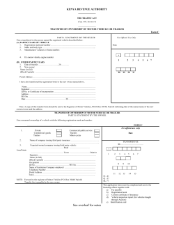


© Copyright 2026