
Bio-cathode materials evaluation in microbial fuel cells:
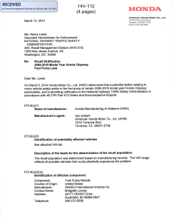
i n t e r n a t i o n a l j o u r n a l o f h y d r o g e n e n e r g y x x x ( 2 0 1 2 ) 1 e8
Available online at www.sciencedirect.com
journal homepage: www.elsevier.com/locate/he
Bio-cathode materials evaluation in microbial fuel cells:
A comparison of graphite felt, carbon paper
and stainless steel mesh materials
Yaping Zhang a,b,1, Jian Sun a,b,2, Yongyou Hu a,b,*, Sizhe Li a,b,3, Qian Xu a,b,4
a
Ministry of Education Key Laboratory of Pollution Control and Ecosystem Restoration for Industrial Agglomeration Area, College of
Environmental Science and Engineering, South China University of Technology, Guangzhou 510006, China
b
State Key Lab of Pulp and Paper Engineering, College of Light Industry and Food Science, South China University of Technology,
Guangzhou 510640, China
article info
abstract
Article history:
The choice of the cathode material is crucial for every bio-cathode microbial fuel cell (MFC)
Received 9 June 2012
setup. The commonly used biocathode materials, Graphite felt (GF), carbon paper (CP) and
Received in revised form
stainless steel mesh (SSM) were compared and evaluated in terms of current density,
8 August 2012
power density, and polarization. The maximum current density and power density of the
Accepted 13 August 2012
MFC with GF-biocathode achieved 350 mA m2 and 109.5 mW m2, which were higher than
Available online xxx
that of the MFC with CP-biocathode (210 mA m2 and 32.7 mW m2) and the MFC with SSMbiocathode (18 mA m2 and 3.1 mW m2). The polarization indicated that the biocathode
Keywords:
was the limiting factor for the three MFC reactors. Moreover, cyclic voltammetry (CV)
Microbial fuel cell
showed that the microorganisms on the biocathode played a major role in oxygen reduc-
Biocathode
tion reaction (ORR) for GF- and CP-biocathode but SSM-biocathode. Electrochemical
Graphite felt
impedance spectroscopy suggested that GF biocathode performed better catalytic activity
Carbon paper
toward ORR than that of CP- and SSM-biocathode, also supported by CV test. Additionally,
Stainless steel mesh
the MFC with GF-biocathode had the highest Coulombic Efficiency. The results of this study
demonstrated GF was the most suitable biocathode for MFCs application among the three
types of materials when using anaerobic sludge as inoculums.
Copyright ª 2012, Hydrogen Energy Publications, LLC. Published by Elsevier Ltd. All rights
reserved.
1.
Introduction
Microbial fuel cell (MFC) is a bio-electrochemical device that
utilizes microorganisms as catalysts to decompose organic or
inorganic matter and simultaneously harvest electricity [1,2].
The conventional MFC consists of an electronegative bioanode
and an electro positive abiotic cathode that are separated by
a proton exchange membrane [3]. Cathode plays the role of an
* Corresponding author. College of Environmental Science and Engineering, South China University of Technology, Guangzhou 510006,
China. Tel.: þ86 20 39380506; fax: þ86 20 39380508.
E-mail addresses: [email protected] (Y. Zhang), [email protected] (J. Sun), [email protected] (Y. Hu), scutlsz@gmail.
com (S. Li), [email protected] (Q. Xu).
1
Tel.: þ86 15920480187.
2
Tel.: þ86 20 39383779.
3
Tel.: þ86 15989036737.
4
Tel.: þ86 15013030126.
0360-3199/$ e see front matter Copyright ª 2012, Hydrogen Energy Publications, LLC. Published by Elsevier Ltd. All rights reserved.
http://dx.doi.org/10.1016/j.ijhydene.2012.08.064
Please cite this article in press as: Zhang Y, et al., Bio-cathode materials evaluation in microbial fuel cells: A comparison of
graphite felt, carbon paper and stainless steel mesh materials, International Journal of Hydrogen Energy (2012), http://
dx.doi.org/10.1016/j.ijhydene.2012.08.064
2
i n t e r n a t i o n a l j o u r n a l o f h y d r o g e n e n e r g y x x x ( 2 0 1 2 ) 1 e8
electron sink to accept electrons and protons that are
produced from the anodic oxidation of substrates. Generally,
oxygen is the preferred electron acceptor due to its limitless
availability, high redox potential, and the lack of chemical
waste product [4]. However, the sluggish kinetics of the
oxygen reduction reaction (ORR) in a medium at a pH near
neutral diminishes the oxygen cathode performance [5,6].
Thus, several types of catalysts, such as platinum [5],
manganese oxides [7,8], iron complexes [4,9], and cobalt
complexes [10], have been investigated as cathodic catalysts
to enhance the ORR (decrease the overpotential) in MFCs.
Unfortunately, these catalysts are often expensive, unsustainable or time-consuming in preparation, and might be
subject to poisoning or secondary pollution, which is detrimental to further scale up in waste treatment scenarios.
Recently, microbial bio-cathodes in which microorganisms
are the electrocatalytic agents of the desired oxygen reduction
reaction have received considerable attention [1,2]. He and
Angenent [11] reviewed several possible biological cathodic
processes, which included the reduction of oxygen. Clauwaert
et al. [12] firstly demonstrated bio-cathode MFC using microorganisms as catalyst and achieved the reduction of oxygen
and nitrite. Compared with an abiotic cathode MFC, microbial
bio-cathode MFC has the advantage of self-regeneration of the
catalyst, low cost, sustainability, and greatest activity at
neutral pH. The microbial metabolism in bio-cathodes may
also be utilized to produce valuable products or to remove
unwanted compounds, for example, hydrogen [13] or methane
[14] bioproduction, nitrate [12] or perchlorate [15] reduction.
Electrode material is known to play an important role in
MFCs. The characteristics and configuration of biocathode
materials are the major factors affecting the performance of
biocathode [16]. A wide variety of materials have been
examined as bio-cathodes in MFCs, including carbon paper
[17], graphite fiber brush [18], graphite felt [12], and stainless
steel mesh [19]. De Schamphelaire et al. [20] reported that
carbon felt was more suitable than stainless mesh for biocathodes. In another study under a polarized potential of
0.6 V vs Ag/AgCl, stainless steel performed better than
graphite in supporting biocathode when the reactor was
inoculated with Geobater sulfurreducens [21]. The interaction
between the microbial biofilms and electrode surface has to be
considered to be decisive for the overall cathode performance,
such as microbial attachment, electron transfer, electrode
resistance and the rate of electrode surface reaction [16,22].
Thus, the choice of the cathode material is crucial for every
bio-cathode MFC setup. Nevertheless, to our knowledge, no
systematically comparative study on the bioelectrocatalytic
activity of mixed culture microbial biofilms on different biocathode materials using an identical source of bacteria as
inoculums has been conducted so far.
In this study, we present the investigation of MFCs with
three different materials used as bio-cathodes for oxygen
reduction based on aerobic microorganisms as catalysts.
Performance of these bio-cathode MFCs were compared and
evaluated via current density, power density, and polarization
curves. Moreover, the electrochemical capability of cathodic
biofilms and the electrochemical impedance behavior of the
three different bio-cathodes were characterized by cyclic
voltammetry
(CV)
and
electrochemical
impedance
spectroscopy (EIS), respectively. This work aimed to study and
compare the commonly used biocathode materials, Graphite
felt (GF), carbon paper (CP) and stainless steel mesh (SSM) in
MFCs, and could help to advance the knowledge base needed
for the biocathode MFC designs and applications.
2.
Materials and methods
2.1.
MFC construction and operation
The anodic chamber was 2 cm long and 5 cm in diameter and
its volume was 40 mL with a net volume (liquid volume) of
30 mL. For the MFC start-up, the carbon paper coated with Pt
of 0.5 mg cm2 (Shanghai Hesen Co., Ltd.) was used as the
cathode. The coated side of the cathode was placed facing the
cation exchange membrane (CEM, Zhejiang Qianqiu Group
Co., Ltd.), with the uncoated side directly exposed to air.
Graphite felt with a projected surface area of 7 cm2 was used
as an anode without further treatment and was positioned in
the chamber at a distance of 0.5 cm from the CEM. The singlechamber MFC reactors were inoculated using anaerobic
sludge collected from the Liede municipal wastewater treatment plant, Guangzhou, China. All reactors were fed with
a medium containing sodium acetate (1000 mg L1), a phosphate buffer solution (PBS, 100 mM), minerals (12.5 mL L1),
and vitamin solution (12.5 mL L1) [23].
After the output voltage was stabilized at 350 mV (with an
external resistance of 1000 U), the MFC was operated in a dualchamber model. The cathodic chamber was of the same shape
and size to the anodic chamber. Graphite felt (GF, thickness of
5 mm, diameter of 15 mm, Beijing Sanye Co., Ltd.), carbon
paper (CP, thickness of 0.35 mm, diameter of 10 mm, Shanghai
Hesen Co., Ltd.) and stainless steel mesh (SSM, thickness of
100 mm, diameter of 50 mm, Anping Count Resen Screen Co.,
Ltd. China), with a projected surface area of 7 cm2, were used
as the cathode, respectively. Prior to use, these electrodes
were soaked in the mixture of H2SO4eHNO3 (volume ratio: 3:1)
for 1 h and subsequently in de-ionized water for 24 h. The biocathodic chamber inoculation was the same as the anodic
chamber and was fed with a similar medium to the anode
without the sodium acetate. The cathodic chamber was
continuously aerated with air as a cathodic electron acceptor
by using a fish pump. All MFCs were operated in fed-batch
mode and conducted in a temperature-controlled room at
30 1 C. The anode solution was refreshed when the voltage
decreased to below 20 mV.
2.2.
Analysis and calculation
The voltage of the MFC across a 1000 U external resistor was
recorded every 5 min with a multimeter and a data acquisition
system (Model 2700, Keithly Instruments, USA). Polarization
curves were obtained by varying the external resistance (Rex)
over a range from 50 to 8000 U when the voltage output
approached a steady and repeatable state. Current density
(A m2) was calculated as I ¼ U/(RexS ), and power density
(mW m2) was calculated according to P ¼ 1000 UI/A, where I
(A) is the current, U (V) is the voltage, and A (m2) is the projected surface area of the cathode.
Please cite this article in press as: Zhang Y, et al., Bio-cathode materials evaluation in microbial fuel cells: A comparison of
graphite felt, carbon paper and stainless steel mesh materials, International Journal of Hydrogen Energy (2012), http://
dx.doi.org/10.1016/j.ijhydene.2012.08.064
i n t e r n a t i o n a l j o u r n a l o f h y d r o g e n e n e r g y x x x ( 2 0 1 2 ) 1 e8
3
The soluble chemical oxygen demands (COD) were
measured according to standard methods [24] and the COD
removal
efficiency
(dCOD)
was
calculated
as
dCOD ¼ (CODint CODout)/CODint 100%, where CODint
represents the initial COD concentration (mg L1) in the feed
and CODout denotes COD concentration at the end of the batch
test. The Coulombic Efficiency (CE) was obtained as CE
(%) ¼ CP/CT 100%, where CP is the total Coulombs calculated
by integrating the current over time, and CT is the theoretical
amount of coulombs based on COD removal by assuming
4 mol of electrons/mol of COD.
Electrochemical analysis of cathodic biofilms and the
electrochemical impedance behavior of the three different
bio-cathodes in MFCs were investigated by cyclic voltammetry (CV) and electrochemical impedance spectroscopy
(EIS), which were performed using an electrochemical
workstation (Model 2273, Princeton Applied Research) with
a three-electrode consisting of a working electrode (the
three different bio-cathodes), a saturated calomel electrode
(SCE, þ0.242 V vs standard hydrogen electrode, SHE) reference electrode, and a platinum foil counter electrode. CV
tests were performed under open circuit voltage (OCV)
conditions and the voltage was changed from 0.6 V to 0.3 V
in forward and reverse scans at a scan rate of 25 mV s1. EIS
tests were conducted under OCV conditions over
a frequency range of 10 kHze5 mHz with sinusoidal
perturbation of 10 mV amplitude and the obtained data were
fitted and simulated to predetermined equivalent electrical
circuit and were then analyzed using ZSimpWin 3.10 software (Echem, US).
The surface morphologies of bio-cathodes were observed
by an environmental scanning electron microscope (SEM) (XL30, Philips Holland). Before observation, the bio-cathodes
sample with bacterial was collected and fixed overnight with
paraformaldehyde and glutaraldehyde in a buffer solution
(0.1 M cacodylate, pH ¼ 7.5, 4 C), followed by washing and
dehydration in water/ethanol. Samples were then coated with
Pt before SEM observation.
3.
Results and discussion
3.1.
Power output and polarization
Stable voltage (350 mV, 1 KU) produced from the MFCs with Pt
cathodic catalyst was observed in several consecutive cycles,
showing that exoelectrogenic biofilm had been acclimated on
anode. The MFC was then installed with a two-chamber mode
and the anaerobic sludge was inoculated into the cathode
chamber. To our knowledge, GF and CP are commonly used as
anode materials for MFCs [12,17], while SSM used for marine
MFCs [21], and they performed differently. Their performance
as biocathode was also different, as shown in Fig. 1A and B. In
the MFC with GF, the maximum current density and
maximum power density reached 350 mA m2 and
109.5 mW m2, respectively. By comparison, those were
210 mA m2 and 32.7 mW m2 for the MFC with CP, while only
18 mA m2 and 3.1 mW m2 for the MFC with SSM, respectively. During the 50 days operation, the current density of all
the three MFCs kept at a stable level.
Fig. 1 e Performance of MFC equipped with graphite felt
(GF), carbon paper (CP) and stainless steel mesh (SSM) as
biocathode: (A) current density as a function of time, (B)
power density and cell polarization curves, and (C) anode
and cathode polarization curves.
The polarization curves in Fig. 1C showed the anode
potential was not appreciably affected by cathode, and the
difference in cathode potential (the open circuit potential and
slop of the cathode polarization curve) was consistent with
the orders in power density for MFCs with different cathode
materials. For instance, the open circuit potential of SSM
biocathode (5.9 mV vs SCE) was lower than that of GF
(54.6 mV vs SCE) and CP biocathode (76.1 mV vs SCE). Also, the
Please cite this article in press as: Zhang Y, et al., Bio-cathode materials evaluation in microbial fuel cells: A comparison of
graphite felt, carbon paper and stainless steel mesh materials, International Journal of Hydrogen Energy (2012), http://
dx.doi.org/10.1016/j.ijhydene.2012.08.064
4
i n t e r n a t i o n a l j o u r n a l o f h y d r o g e n e n e r g y x x x ( 2 0 1 2 ) 1 e8
slop of SSM biocathode polarization curve showed a more
rapid decrease as compared to that of GF and CP biocathode.
As a result, the difference in performance of the MFCs can be
attributed to the difference in biocathode performance. The
results obtained in this section showed that GF used as biocathode performed better than CP and SSM, which was
probably due to better growth of microorganisms with electrocatalytic oxygen reducing activity on GF-biocathode. It
seems most likely that the rough surface of GF is responsible
for the better development of electrochemically active
microbial biofilm onto the electrode. However, the current and
power density of the MFC with GF, CP and SSM were lower
than those reported previously [25,26]. In addition, it was
evident from Fig. 1C that the cathode was the limiting factor in
these MFCs. For example, in the MFC with GF, with increased
current densities of 0e1.33 A m2, the anode potential
increased insignificantly from 548 to 500 mV, whereas the
biocathode potential dropped from 55 to 454 mV. The larger
driving force with an overpotential of 510 mV required for the
biocathode compared to the value of 48 mV required for the
anode indicated that power generation from the MFC was
dominated by cathode polarization. Therefore, biologicallycatalyzed reactions toward oxygen reduction reaction (ORR)
of the biocathode could be improved to enhance the MFC
performance. Potentially, modification of anode electrode
surface to enhance the electron transfer between electrode
and bacteria might be employed to strengthen the electron
transfer rate to oxygen in ORR of biocathode in MFCs [17] and
this experiment is conducting in our laboratory. Moreover, CV
and EIS tests were carried out to determine the electrocatalytic behavior of different biocathode materials in MFCs in
the following part.
3.2.
Fig. 2 e Cyclic voltammetry curves for (A) raw cathode
electrodes and (B) cathode electrodes with biofilm attached.
Electrochemical characterization of the biocathode
CV was performed to examine the catalytic behavior of the
biocathodes. As shown in Fig. 2A, no distinct redox peak was
observed from all three abiotic cathode either in air- or
nitrogen-saturation solution, but all the currents were higher
in air-saturation solution than that in nitrogen-saturation
solution because of the oxygen reduction on the abiotic electrode. By comparison, the abiotic GF exhibited higher catalytic
activity than the abiotic CP and SSM electrodes. In order to
further ascertain the biofilm-associated ORR, the three biocathodes were tested under the same conditions. As shown in
Fig. 2B, for the GF biocathodes, the maximum current of 9 mA
was reached at a cathode potential of 0.6 V vs SCE in airsaturation solution. However, the current was considerably
decreased to 0.8 mA when the solution was purged with
nitrogen, indicating that indeed oxygen reduction was the
reaction that was catalyzed. When comparing these results
with the CV of abiotic cathode in air-saturation solution
(Fig. 2A), the maximum current of GF biocathodes was much
higher than that of the abiotic GF cathodes, suggesting that
indeed the ORR was catalyzed by the microorganisms. The CP
biocathode showed similar catalytic behavior to the GF biocathode, the main difference being a lower maximum current
compared to the GF biocathode. In addition, one pair of redox
wave was observed for the GF and CP biocathodes either in airor nitrogen-saturation solution (Fig. 2B). It proved that some
components in the culture could be oxidized or reduced
during the potential sweep. One possibility is that they were
redox active compounds excreted by microorganism, some of
which have the ability to react with oxygen and give an electrocatalytic effect on the CV [27]. In contrast, the CV of SSM
Fig. 3 e EIS (Nyquist plots) of the biocathode in MFCs. The
inset shows the details at high frequency.
Please cite this article in press as: Zhang Y, et al., Bio-cathode materials evaluation in microbial fuel cells: A comparison of
graphite felt, carbon paper and stainless steel mesh materials, International Journal of Hydrogen Energy (2012), http://
dx.doi.org/10.1016/j.ijhydene.2012.08.064
i n t e r n a t i o n a l j o u r n a l o f h y d r o g e n e n e r g y x x x ( 2 0 1 2 ) 1 e8
Fig. 4 e COD removal and coulombic efficiency (CE) of
biocathodic materials.
biocathode in Fig. 2B showed similar behavior and no redox
wave in air-saturation solution as compared with that in
nitrogen-saturation solution, implying that the microorganism developed poorly on the SSM electrode. The results
demonstrated that GF biocathode performed better catalytic
activity toward ORR than that of CP and SSM biocathodes,
which was consistent with the power generation. Clearly,
further studies are warranted to better understand the
mechanism of ORR in biocathodes.
After 50 days operation from initiation, the charge
transfer resistance (Rct) and diffusion resistance (Rdif) were
5
estimated from Nyquist plots (Fig. 3) to investigate the biocathode performance of MFCs. The inset in Fig. 3 illustrated the high-frequency part of the result. All plots consisted of semicircles at high-frequencies and straight-line
features in a low-frequency region, corresponding with the
Rct at the cathode interface and the Rdif (diffusion process of
oxygen at the electrode/electrolyte interface), respectively.
As seen from the inset in Fig. 3, plots of GF-biocathode and
CP-biocathode revealed a smaller depressed semi-circle
than that of SSM-biocathode. Here, the value of Rct is indicated by the diameter of the first semicircle in the Nyquist
curve [28]. As shown in Fig. 3, the Rct of GF-biocathode was
approximately 11 U, whereas that of CP-biocathode was
approximately 23 U, and both were much lower than that of
SSM-biocathode (w820 U). It is well known that the electrochemical reaction rate is inversely proportional to the
electron transfer resistance (Rct) [29]. Therefore, it can be
concluded that GF-biocathode exhibited the best catalytic
behavior toward ORR. This result also indicated that the
SSM-biocathode required a greater overpotential than that
of GF-biocathode and CP-biocathode. This could be one of
reasons why the MFCs with GF-biocathode and CPbiocathode showed a better performance than the MFC
with SSM-biocathode.
The straight line region over low-frequency of SSMbiocathode was significantly smaller than that of GFbiocathode and CP-biocathode as shown by the linear
portion. This revealed that Rdif was dominant for GFbiocathode and CP-biocathode but SSM-biocathode. The
high values of Rdif for GF-biocathode and CP-biocathode
showed that the diffusion term significantly contributed to
the oxygen reduction process, which was partly a result of the
Fig. 5 e SEM images of biocathodes from (A) graphite felt, (B) carbon paper, (C) stainless steel mesh and (D) amplification of
stainless steel mesh (D).
Please cite this article in press as: Zhang Y, et al., Bio-cathode materials evaluation in microbial fuel cells: A comparison of
graphite felt, carbon paper and stainless steel mesh materials, International Journal of Hydrogen Energy (2012), http://
dx.doi.org/10.1016/j.ijhydene.2012.08.064
6
i n t e r n a t i o n a l j o u r n a l o f h y d r o g e n e n e r g y x x x ( 2 0 1 2 ) 1 e8
poor solubility, the shortage and limited diffusivity of oxygen
in water [30]. This meant that the mass transfer (diffusion
process) was the main factors limiting the performance of GFbiocathode and CP-biocathode. It was reported that increasing
aeration fluxes or pumping pure oxygen instead of air could
lead to a decrease in diffusion resistance [31]. Therefore, these
methods could be employed and helpful for improving the
performance of GF- and CP-biocathode. When compared with
GF- and CP-biocathode, the SSM-biocathode had a smaller Rdif
and a larger Rct, revealing that the ORR rate at SSM-biocathode
was not limited by diffusion but by charge transfer, which was
likely due to the less developed bacteria on SSM-biocathode.
Overall, the EIS tests demonstrated that GF was the most
suitable biocathode for MFCs application among the three
materials, which was in good agreement with the result of the
current generation and CV test.
3.3.
COD removal and CE
COD removal and CE for different biocathode materials were
calculated upon a batch-operated basis, as shown in Fig. 4.
The acetate removal efficiency remained at a high level for all
MFCs with the three biocathodes. 93.8% and 91.9% of COD was
removed for MFC with GF-biocathode and CP-biocathode,
respectively. These values were a little higher than that of
MFC with SSM-biocathode (86.3%). The MFC with GF-
Table 1 e Cathode materials, configuration and performance in MFCs.
Cathode materials
Electrode
Cathode
configuration size/chamber
volume
Catalyst
MFC
configuration
Maximum
power
density (W m3)
Reference
Graphite felt
Plane
7 cm2; 30 mL
Anaerobic sludge
Dual chamber
2.6
Graphite felt
Plane
110 mL
Carbon paper
Plane
7 cm2; 30 mL
Aerobic/anaerobic
sludge
Anaerobic sludge
Dual-chamber
flat plate MFC
Dual chamber
14.1
(cathode volume)
0.8
Carbon paper
Carbon paper
Plane
Plane
Stainless steel mesh
Plane
9 cm2; 30 mL
25 cm2;
125 mL
7 cm2; 30 mL
Anaerobic sludge
Dual chamber
Mixed culture of
Dual chamber
denitrify bacteria
Anaerobic sludge
Dual chamber
2.5
0.19
(anodic volume)
0.07
Stainless steel mesh
Plane
368 cm2
Earthen pot
Carbon
nanotubes/chitosan-coated
carbon paper
Graphite fiber brush
Carbon cloth
Graphene-coated carbon cloth
Graphite granules/graphite
fiber brush
Plane
9 cm2; 30 mL
Oxidation pond
sewage
Anaerobic sludge
Dual chamber
1.7
(anodic volume)
5.7
[17]
Brush
Plan
Plan
Packed
Aerobic sludge
Anaerobic sludge
Anaerobic sludge
Topsoil from turf
Dual
Dual
Dual
Dual
chamber
chamber
chamber
chamber
68.4 (anodic volume)
8.1 (cathode volume)
16.2 (cathode volume)
99.8 (cathode volume)
[18]
[40]
[40]
[25]
Topsoil from turf
Dual chamber
72.8 (cathode volume)
[25]
Topsoil from turf
Dual-chamber
flat plate MFC
Dual-chamber
flat plate MFC
Dual-chamber
flat plate MFC
Dual-chamber
flat plate MFC
Dual chamber
72.4 (cathode volume)
[25]
20.1 (cathode volume)
[26]
24.3 (cathode volume)
[26]
14.7 (cathode volume)
[26]
32 (total MFC volume)
[41]
Dual chamber
2.55 (total volume)
[42]
Dual chamber
15 (total volume)
[35]
Cylindrical dual
83 (total volume)
chamber with a
internal anode
chamber
[12]
Graphite granules
Packed
Graphite fiber brush
Brush
56 mL
5 cm2; 10 mL
5 cm2; 10 mL
Diameter:
1e5 mm;
51 mL
Diameter:
1e5 mm;
51 mL
51 mL
Semicoke
Packed
110 mL
Activated carbon
Packed
110 mL
Carbon felt
Plane
110 mL
Manganese/iron
solution-modified
Granular carbon
Graphite granules
Packed
Packed
Diameter:
2.5e4 mm;
75 mL
319 mL
Carbon fiber
Packed
12 14 cm;
Manganese oxide-coated
graphite felt
Tubular
40 mL
Aerobic/anaerobic
sludge
Aerobic/anaerobic
sludge
Aerobic/anaerobic
sludge
Digested sludge
Aerobic/anaerobic
sludge
Effluent of anode
chamber
Mixture of
sediment,
aerobic and
anaerobic
sludge
This
study
[16]
This
study
[17]
[34]
This
study
[19]
Please cite this article in press as: Zhang Y, et al., Bio-cathode materials evaluation in microbial fuel cells: A comparison of
graphite felt, carbon paper and stainless steel mesh materials, International Journal of Hydrogen Energy (2012), http://
dx.doi.org/10.1016/j.ijhydene.2012.08.064
i n t e r n a t i o n a l j o u r n a l o f h y d r o g e n e n e r g y x x x ( 2 0 1 2 ) 1 e8
biocathode had the highest CE as compared to that of CP- and
SSM-biocathode, and this agreed with the results of polarization and power measurements. This likely resulted from
faster oxygen reduction kinetics of GF-biocathode with more
developed microorganisms as catalysts, promoting quantitative conversion of organic substrates to Coulombs. However,
the CE in this study was only in the range of 1.5e11.7% at the
external resistance of 1000 U, indicating that a substantial
number of electrons were lost. The factors impact electron
recovery can be complicated and mainly appeared to result
from the diffusion of molecular oxygen from the cathode to
the anode [32,33] and the loss of substrate due to alternative
microbial (such as acetoclastic methanogenesis) processes in
the anode chamber [34].
3.4.
Morphological characterization of biocathodes
SEM images of biocathodes showed sparse coverage of bacteria
(Fig. 5). Specially, Fig. 5A and B suggested biomass attached to
the surface of GF- and CP-biocathode, which was in contrast to
Fig. 5C and D, where significantly less biomass attachment was
visible on the SSM-biocathode. Compared with GF and CP, the
surface of SSM is more smooth, probably less suitable for efficient microbial biofilm formation. The low power production
from MFC with SSM-biocathode seemed due to increased
charge transfer resistance with less developed bacteria on the
cathode. The amounts of bacteria observed on SEM images
were consistent with the results of power generation, EIS test
and polarization behavior as discussed above. Therefore, it is
assumed here that amounts of bacteria on the biocathode
should be one of the factors to determine the charge transfer
resistance and power generation. Overall, the bacterial densities on all the three biocathodes were exceptionally low, which
was similar to previous studies that also showed low microbial
densities on the biocathode for ORR [35]. This could be one of
reasons why the cathode was the limiting factor in biocathode
MFCs. It is more difficult to obtain electron-accepting biofilms
on cathodes under anoxic conditions than it is to produce
exoelectrogenic biofilms on anodes [36]. Thus, surface modifications such as carboxylation, nanostructured materials
modification and immobilization of electron redox mediators
[37e39] likewise to the anode modification should be employed
and could increase the catalytic activity and improve the
colonization on the biocathode.
3.5.
Comparison to previous biocathode studies
Biocathode alleviates the need to use noble metal or nonnoble metal catalysts for ORR, which increases the viability
and sustainability of MFCs. As shown in Table 1, biocathode
electrodes are mainly composed of graphite felt, carbon paper,
graphite granules, graphite fiber brush, carbon fiber, carbon
felt and activated carbon, as well as stainless steel mesh. The
power densities obtained in our test were lower than those of
previously reported in Table 1. Except of biocathode material,
the different reactor configuration, inoculation, operation
parameters and anodic performance might also be responsible for the different performance of MFCs. So this comparison between different studies did not appear to be proper.
However, GF, CP and SSM biocathode should be optimized to
7
improve its performance, thus enhancing the power generation of MFCs. Recently, Liu et al. [17] fabricated a biocathode by
electrodepositing carbon nanotubes and chitosan onto
a carbon paper, and the use of this nanocomposite increased
the maximum power density of MFC by 130%. Zhuang et al.
[40] reported that the maximum power density achieved by
using graphene-modified carbon cloth could be 2 times higher
than that achieved with bare carbon cloth. Exploration of
appropriate nanomaterials to modify biocathode is a new
topic of interest and is required to enhance the performance
of MFCs.
4.
Conclusion
The commonly used biocathode materials, GF, CP, and SSM
were tested and compared to evaluate their behaviors and
suitability in biocathode MFCs when using anaerobic sludge as
inoculums. The MFC with GF-biocathode exhibited the best
electrochemical performance (power generation, polarization,
CV and EIS performance) and the highest utilization for electricity generation (Coulombic Efficiency), followed by CPbiocathode MFC and SSM-biocathode MFC. We demonstrated that GF was the most suitable biocathode for MFCs
application among the three types of materials. The results
obtained in this work could help advance the knowledge base
needed for the biocathode MFC designs and applications.
However, to make the biocathode MFC more effective and
applicable, more studies are required to further elucidate the
biofilm-driven catalysis mechanisms and to optimize the
electrode materials and MFC construction.
Acknowledgments
The authors gratefully acknowledge the financial support
provided by the National Natural Science Fund of China (No.
20977032).
references
[1] Rosenbaum M, Aulenta F, Villano M, Angenent LT. Cathodes
as electron donors for microbial metabolism: which
extracellular electron transfer mechanisms are involved?
Bioresource Technology 2011;102:324e33.
[2] Rabaey K, Rozendal RA. Microbial electrosynthesis e
revisiting the electrical route for microbial production.
Nature Reviews Microbiology 2010;8:706e16.
[3] Logan BE, Hamelers B, Rozendal RA, Schrorder U, Keller J,
Freguia S, et al. Microbial fuel cells: methodology and
technology. Environmental Science & Technology 2006;40:
5181e92.
[4] Zhao F, Harnisch F, Schrorder U, Scholz F, Bogdanoff P,
Herrmann I. Challenges and constraints of using oxygen
cathodes in microbial fuel cells. Environmental Science &
Technology 2006;40:5193e9.
[5] Rismani-Yazdi H, Carver SM, Christy AD, Tuovinen IH.
Cathodic limitations in microbial fuel cells: an overview.
Journal of Power Sources 2008;180:683e94.
Please cite this article in press as: Zhang Y, et al., Bio-cathode materials evaluation in microbial fuel cells: A comparison of
graphite felt, carbon paper and stainless steel mesh materials, International Journal of Hydrogen Energy (2012), http://
dx.doi.org/10.1016/j.ijhydene.2012.08.064
8
i n t e r n a t i o n a l j o u r n a l o f h y d r o g e n e n e r g y x x x ( 2 0 1 2 ) 1 e8
[6] Qiao Y, Bao S, Li C. Electrocatalysis in microbial fuel cellsfrom electrode material to direct electrochemistry. Energy &
Environmental Science 2010;3:544e53.
[7] Zhang L, Liu C, Zhuang L, Li W, Zhou S, Zhang J. Manganese
dioxide as an alternative cathodic catalyst to platinum in
microbial fuel cells. Biosensors and Bioelectronics 2009;24:
2825e9.
[8] Zhang Y, Hu Y, Li S, Sun J, Hou B. Manganese dioxide-coated
carbon nanotubes as an improved cathodic catalyst for
oxygen reduction in a microbial fuel cell. Journal of Power
Sources 2011;196:9284e9.
[9] Zhao F, Harnisch F, Schroder U, Scholz F, Bogdanoff P,
Herrmann I. Application of pyrolysed iron(II) phthalocyanine
and CoTMPP based oxygen reduction catalysts as cathode
materials in microbial fuel cells. Electrochemistry
Communications 2005;7:1405e10.
[10] Deng L, Zhou M, Liu C, Liu L, Liu C, Dong S. Development of
high performance of Co/Fe/N/CNT nanocatalyst for oxygen
reduction in microbial fuel cells. Talanta 2010;81:444e8.
[11] He Z, Angenent LT. Application of bacterial biocathodes in
microbial fuel cells. Electroanalysis 2006;18:2009e15.
[12] Clauwaert P, Van der Ha D, Boon N, Verbeken K, Verhaege M,
Rabaey K, et al. Open air biocathode enables effective
electricity generation with microbial fuel cells.
Environmental Science & Technology 2007;41:7564e9.
[13] Rozendal RA, Jeremiasse AW, Hamelers HVM, Buisman CJN.
Hydrogen production with a microbial biocathode.
Environmental Science & Technology 2008;42:629e34.
[14] Wang A, Liu W, Cheng S, Xing D, Zhou J, Logan BE. Source of
methane and methods to control its formation in single
chamber microbial electrolysis cells. International Journal of
Hydrogen Energy 2009;34:3653e8.
[15] Butler CS, Clauwaert P, Green SJ, Verstraete W, Nerenberg R.
Bioelectrochemical perchlorate reduction in a microbial fuel
cell. Environmental Science & Technology 2010;44:4685e91.
[16] Wei J, Liang P, Huang X. Recent progress in electrodes for
microbial fuel cells. Bioresource Technology 2011;102:9335e44.
[17] Liu X-W, Sun X-F, Huang Y-X, Sheng G-P, Wang S-G, Yu H-Q.
Carbon nanotube/chitosan nanocomposite as
a biocompatible biocathode material to enhance the
electricity generation of a microbial fuel cell. Energy &
Environmental Science 2011;4:1422e7.
[18] You SJ, Ren NQ, Zhao QL, Wang JY, Yang FL. Power
generation and electrochemical analysis of biocathode
microbial fuel cell using graphite fibre brush as cathode
material. Fuel Cells 2009;9:588e96.
[19] Behera M, Jana PS, Ghangrekar MM. Performance evaluation
of low cost microbial fuel cell fabricated using earthen pot
with biotic and abiotic cathode. Bioresource Technology
2010;101:1183e9.
[20] De Schamphelaire L, Boeckx P, Verstraete W. Evaluation of
biocathodes in freshwater and brackish sediment microbial
fuel cells. Applied Microbiology Biotechnology 2010;87:
1675e87.
[21] Dumas C, Mollica A, Fe´ron D, Basse´guy R, Etcheverry L,
Bergel A. Marine microbial fuel cell: use of stainless steel
electrodes as anode and cathode materials. Electrochimica
Acta 2007;53:468e73.
[22] Huang L, Regan JM, Quan X. Electron transfer mechanisms,
new applications, and performance of biocathode microbial
fuel cells. Bioresource Technology 2011;102:316e23.
[23] Lovley D, Phillips E. Novel mode of microbial energy
metabolism: organic carbon oxidation coupled to
dissimilatory reduction of iron or manganese. Applied and
Environmental Microbiology 1988;54:1472e80.
[24] APHA, AWWA, WPCF. Standard methods for the
examination of water and wastewater. 20th ed. Washington,
DC: American Public Health Association; 1998.
[25] Zhang G-d, Zhao Q-l, Jiao Y, Zhang J-n, Jiang J-q, Ren N, et al.
Improved performance of microbial fuel cell using
combination biocathode of graphite fiber brush and graphite
granules. Journal of Power Sources 2011;196:6036e41.
[26] Wei J, Liang P, Cao X, Huang X. Use of inexpensive semicoke
and activated carbon as biocathode in microbial fuel cells.
Bioresource Technology 2011;102:10431e5.
[27] Freguia S, Tsujimura S, Kano K. Electron transfer pathways
in microbial oxygen biocathodes. Electrochimica Acta 2010;
55:813e8.
[28] He Z, Mansfeld F. Exploring the use of electrochemical
impedance spectroscopy (EIS) in microbial fuel cell studies.
Energy & Environmental Science 2009;2:215e9.
[29] Zhang Y, Sun J, Hou B, Hu Y. Performance improvement of
air-cathode single-chamber microbial fuel cell using
a mesoporous carbon modified anode. Journal of Power
Sources 2011;196:7458e64.
[30] Ji MB, Wei ZD, Chen SG, Xia MR, Zhang Q, Qi XQ, et al.
Electrochemical impedance spectroscopy evidence of
dimethyl-silicon-oil enhancing O2 transport in a porous
electrode. Electrochimica Acta 2011;56:4797e802.
[31] Ter Heijne A, Schaetzle O, Gimenez S, Fabregat-Santiago F,
Bisquert J, Strik DPBTB, et al. Identifying charge and mass
transfer resistances of an oxygen reducing biocathode.
Energy & Environmental Science 2011;4:5035e43.
[32] Freguia S, Rabaey K, Yuan Z, Keller J. Sequential
anodeecathode configuration improves cathodic oxygen
reduction and effluent quality of microbial fuel cells. Water
Research 2008;42:1387e96.
[33] Cheng S, Liu H, Logan BE. Increased performance of singlechamber microbial fuel cells using an improved cathode
structure. Electrochemistry Communications 2006;8:
489e94.
[34] Lefebvre O, Al-Mamun A, Ng HY. A microbial fuel cell
equipped with a biocathode for organic removal and
denitrification. Water Science and Technology 2008;58:
881e5.
[35] Rabaey K, Read ST, Clauwaert P, Freguia S, Bond PL,
Blackall LL, et al. Cathodic oxygen reduction catalyzed by
bacteria in microbial fuel cells. The ISME Journal 2008;2:
519e27.
[36] Mancini S, Abicht HK, Karnachuk OV, Solioz M. Genome
sequence of Desulfovibrio sp. A2, a highly copper resistant,
sulfate-reducing bacterium isolated from effluents of
a zinc smelter at the Urals. Journal of Bacteriology 2011;
193:6793e4.
[37] Liu JL, Lowy DA, Baumann RG, Tender LM. Influence of anode
pretreatment on its microbial colonization. Journal of
Applied Microbiology 2007;102:177e83.
[38] Wang K, Liu Y, Chen S. Improved microbial electrocatalysis
with neutral red immobilized electrode. Journal of Power
Sources 2011;196:164e8.
[39] Zou YJ, Xiang CL, Yang LN, Sun LX, Xu F, Cao Z. A
mediatorless microbial fuel cell using polypyrrole coated
carbon nanotubes composite as anode material.
International Journal of Hydrogen Energy 2008;33:4856e62.
[40] Zhuang L, Yuan Y, Yang G, Zhou S. In situ formation of
graphene/biofilm composites for enhanced oxygen reduction
in biocathode microbial fuel cells. Electrochemistry
Communications 2012;21:69e72.
[41] Mao Y, Zhang L, Li D, Shi H, Liu Y, Cai L. Power generation
from a biocathode microbial fuel cell biocatalyzed by ferro/
manganese-oxidizing bacteria. Electrochimica Acta 2010;55:
7804e8.
[42] Chen GW, Cha JH, Choi SJ, Lee TH, Kim CW. Characterization
of an open biocathode microbial fuel cell for electricity
generation and effluent polish. Korean Journal of Chemical
Engineering 2010;27:828e35.
Please cite this article in press as: Zhang Y, et al., Bio-cathode materials evaluation in microbial fuel cells: A comparison of
graphite felt, carbon paper and stainless steel mesh materials, International Journal of Hydrogen Energy (2012), http://
dx.doi.org/10.1016/j.ijhydene.2012.08.064


© Copyright 2026