
Cooling - UCSB College of Engineering
* Some of the images used in these slides are taken
from the internet for instructional purposes only
Building Energy Systems
- HVAC: Cooling -
Bryan Eisenhower
Associate Director
Center for Energy Efficient Design
Researcher and Lecturer
Department of Mechanical Engineering
UCSB
Winter 2015
Systems - of - Systems
Outdoors
Thermal Zone
Fresh Air
Systems - of - Systems
Outdoors
Thermal Zone
Fresh Air
Hot Water
Systems - of - Systems
Outdoors
Thermal Zone
Fresh Air
Hot Water
Chilled water
Systems - of - Systems
Outdoors
Thermal Zone
Fresh Air
Hot Water
Chilled water
Refrigerant
Systems - of - Systems
Outdoors
Thermal Zone
Fresh Air
Hot Water
Chilled water
Refrigerant
Cooling Tower
Systems - of - Systems
Outdoors
Thermal Zone
Fresh Air
Hot Water
Chilled water
Refrigerant
Cooling Tower
Controllers
HVAC
Occupied
area
Past
Air
Distribution
Earth
Next lecture
Secondary
Systems
Now
Primary
Systems
EnergyPlus documentation
HVAC
Cooling:
(Natural Ventilation)
Refrigeration cycles
Absorption cycles
Evaporation
Heating:
(Natural through envelope – solar, internal gains)
Boilers (water / steam)
Furnaces
Electric
Refrigeration
Natural – solar collector
** These subjects cover how to create cooling/heating, distribution comes later
Refrigeration Cycles
Compression and expansion transfers heat:
Heat removed from cycle
1. A compressor draws in gas and
compresses it
Condenser
This places energy into the fluid
(usually electrical energy > thermal
Expansion
Compressor
energy)
2. A condenser takes this very hot fluid and
allows it to cool which then turns it
Evaporator
(condenses) into liquid
Energy
added
Energy leaves the fluid, often to the
Heat added to cycle
outdoor environment
3. An expansion valve expands the liquid so
that it is a low pressure and very cold liquid
Very little energy transfer here
4. An evaporator is used to evaporate the
liquid into a gas so that it can be
compressed again
The evaporator draws in heat (usually
from the indoors)
wikipedia
Refrigeration Cycles
Types of refrigeration / vapor
compression cycles:
Chillers (typically create chilled water
or ice)
Air conditioners (typically create cold
air)
Heat Pumps (typically create cold or
hot air or water)
Chillers stand out as being large
in size and with large connections
Aside from automotive, AC’s and Heat
Pumps look very similar
www.unitedindustries.com.au
parkercoloradoairconditioning.com
retekool.en.made-in-china.com
www.diytrade.com
Compressors
Compressors:
Reciprocating
Most common, much like an auto engine (piston
and cylinder)
Screw
Two meshed screws
Rotary
Rotating gears (small)
Centrifugal
Like a fan
Scroll
Spiral scroll gears
Capacity vs. vibration / noise are
some of the main tradeoffs in
compressor design
Trane
Mostly driven by electric motors, but
can be engine driven, etc.
<1
1
10
100
1000 (Tons)
Screw
Rotary
Scroll
Reciprocating
*Adapted from Mitchell
Centrifugal
chinaxuemei.en.made-in-china.com
1 Ton = 3.52 kW
www.directindustry.com
Expansion Devices
Depending on the conditions (e.g. full load,
partial load, start/stop), the pressure
differential between the high pressure and
low pressure sides needs to be changed
Expansion device
Historically a thermostatic device is used
maintained the desired pressure differential,
now electronic options are available
Thermostatic
Electronic
www.smartclima.com
honda-tech.com
Heat transfer
The heat added and removed from the cycle can
be done in many ways:
Evaporator (cold side)
Chilled water loop (liquid)
Direct expansion (air)
Condenser (hot side)
Cooling tower loop (liquid)
Air cooled
Heat transfer
Refrigerant / Air heat exchangers (also known as coils)
Heat exchanger coils
Refrigerant can be cooled or heated based by passing
it through a heat exchanger that has forced air on the
other side of it
A typical residential AC is
called a split system
because the condenser
and evaporator are
separated in space
Split system
www.e-refrigeration.com
www.rae-corp.com
Air cooled condenser on a chiller
When the evaporator is in
the airstream it is called a
direct expansion (DX) unit
This house has
refrigerant coming/going
to a AC unit (split)
This house has an air
duct coming/going to a
AC unit (packaged)
www.amanahac.com
www.diytrade.com
Heat transfer
Refrigerant / Liquid heat exchangers
Heat can be transported to/away from the
refrigeration cycle with liquid as well.
Liquid to refrigerant heat exchangers used
close-fitting pipes or plates to transmit the
heat
More on what happens after this in the next
lecture
renewableenergyengineering.com
www.unitedindustries.com.au
Refrigerants
Ammonia was one of the first refrigerants, not safe for residential
Halocarbons (carbon + chlorine & fluorine) = C’s below
Many halocarbons have adverse environmental effects because of long break down periods
Balance between toxicity, flammability, and long life
Ammonia, Water, CO2
Refrigerant
CFCs/HCFC
s
HFCs
HCs
Natural
R12
R22
R134
a
R410
A
R404
A
R29
0
R600
a
R71
7
R71
8
R74
4
ODP
1
0.05
0
0
0
0
0
0
0
0
GWP (100yr)
7100
1500
1300
1730
3260
20
20
2
<1
1
Flammable
No
No
No
No
No
Hig
h
High
Low
No
No
Toxic
No
No
No
No
No
No
No
Yes
No
No
Relative Price to
R22
-
1
4.0
5.0
~5.0
0.3
~0.3
0.2
<
0.1
0.1
Vol. Capacity
[Btu/ft3]
89
148
104
236
174
133
55
160
0.63
715
Critical Temp. [F]
234
205
214
163
162
206
275
270
705
88
Pressure at 70F
[psia]
85
136
86
215
163
125
45
129
0.36
853
HVAC
Cooling:
(Natural Ventilation)
Refrigeration cycles
Absorption cycles
Evaporation
Heating:
(Natural – solar, internal gains)
Boilers (water / steam)
Furnaces
Electric
Refrigeration cycles used as heating
Refrigeration
This is a little bit out of order, but since
Natural – solar collector
we are on the topic…..
Heat Pumps
A heat pump ‘pumps’ heat from one
location to another.
The temperature of the heat does
not have to be too significant (e.g. a
HP can extract heat from 40F air in
the winter
The source and sink for the heat
can be of many choices:
Outside air, earth, lakes, ocean,
inside water, inside air
Reversing heat pump
http://www.heatpump-reviews.com
http://hepisontheway.com
Heat Pumps
Heat pumps can be used to pump heat out of or
into
Air
Ground
Water
….
Ground / earth based heat rejection is typically
more stable than atmospheric air and may be at
more beneficial temperatures
Heat removed from cycle
Ground,
water, ….
Condenser
Expansion
Compressor
Evaporator
Energy
added
Heat added to cycle
gaci.biz
http://greenwise.weebly.com/
Heat Pumps
As with economizers, geothermal heat pump
applications vary in their effectiveness based
on where you are
Installation costs are usually pretty high, but
have been falling in recent years
** Geothermal power generation not covered
in this class
http://www.buildingscience.com/
nwcommunityenergy.org
Heat Pumps @ UCSB
16,500 sf LEED-Gold complex
at UC Santa Barbara is the
result of a partnership
between the university and
NOAA.
Heating – baseboard hydronic
heaters with hot water from
ocean source heat pump
Cooling – windows, ceiling
fans, chilled water from ocean
source heat pump for
equipment / computer rooms
Heat Pumps @ UCSB
Heating
Ocean
UCSB ocean source
heat pump diagram
Cooling
Research Direction
There is ongoing research into
designing better components
of refrigeration cycles
- lighter, quieter, more
efficient, cheaper
At the systems level, there is
significant work in identifying
when the refrigeration
equipment needs to be
serviced
- Is there dirt on the heat
exchange surfaces?
- Compressor worn out?
- Loss of refrigerant?
- Can you do this remotely?
Braun @ Purdue
Research Direction
New cycles (or old cycles with new interest) are being developed
Transcritical cycles leave the two-phase boundary by exceeding the critical
point in pressure
Because of this, the condenser becomes a gas cooler (no condensation), and
must operate at very high pressures
Phase change occurs across the expansion valve
New degrees of freedom for control because of the lack of temperature glide
on the condenser
www.achrnews.com
Research Direction
CO2 Heat Pump
3 units heat
(ambient air)
1 unit
electricity
Multiple equilibria
4 units
hot water
Because of the design of the CO2 heat pump, a new control variable is available
Depending on how the machine is started, very efficient or inefficient operation
can occur
Mathematical controls are needed that ensure efficient operation
Control Measurement
Efficiency
CO2 Heat Pump – Startup
CO2 Startup Movie
Physic-based modeling
𝜕𝐴𝜌 𝜕𝑚
+
=0
𝜕𝑡
𝜕𝑧
𝜕 𝐴𝜌ℎ − 𝐴𝜌
𝜕 𝑚ℎ
+
= 𝜋𝐷𝛼(𝑇𝑤 − 𝑇)
𝜕𝑡
𝜕𝑧
Evap. Enthalpy Change
CO2 Heat Pump – Efficient Controller
No control
Control Variable (water flow)
Nonlinear
Control
Insight into a nonlinear controller
that provides robust efficient
operation obtained from model
and tested on prototype
[US 6,813,895, US 7,171,820, US 7,127,905, US 7,010,925, US 7,225,629, US 6,993,921
Eisenhower 2005, 2007, 2009]
Research Direction
Chiller plant optimization
Often more than one chiller is needed to
satisfy the cooling needs of a group of
buildings
For a campus, the available chillers may
range in size, age, efficiency etc.
Research question: As the amount of
cooling changes through the day, which
combination of chillers should be used?
bigladdersoftware.com
Efficiency curves
are different for
each machine
google
HVAC
Cooling:
(Natural Ventilation)
Refrigeration cycles
Absorption cycles
Evaporation
Heating:
(Natural through envelope – solar, internal gains)
Boilers (water / steam)
Furnaces
Electric
Refrigeration
Natural – solar collector
** These subjects cover how to create cooling/heating, distribution comes later
Absorption Cycles
Absorption cycles obtain similar results as the vapor compression cycle by using
heat and chemical reactions
An example:
Heat is added to a ammonia water solution which vaporizes the ammonia
The vapor ammonia is then condensed in a condenser and the liquid ammonia
is taken for cooling
An evaporator is used to partially vaporize the ammonia
Apsorption Cycle
Absorption cycles are desired
because they require very little
electricity and can run off heat
Because of this, they are great
options for combined heat and
power applications
www.eurocooling.com
UTC PureComfort™ CHP System
…Two different control systems, one common function
Capstone MicroTurbines
Carrier Chiller
Gas -> Electricity and hot exhaust
Gas fired burner -> Cold / hot water
Capstone control system
Carrier control system
+
Carrier
Controller
Capstone
Controller
UTRC PureComfort CHP
Goal: Modify Carrier controller for supervisory needs
Necessary Controller Changes
Adjust to operation of chiller to different heat
source:
1. Micro-turbines at full power all 4 microturbines on
2. Micro-turbines load following
a)
All 4 micro-turbines running with power
fluctuations below 60kW
b) 1-2 micro-turbines turned on/off with
power fluctuations greater than 60kW
c) All 4 micro-turbines shut down
3. Include Damper Valve Model
4. Start/Stop Procedures
a)
Chiller does not start if all 4 micro-turbines
are turned off
b) Chiller shuts down safely if all 4
c) micro-turbines are shut down
5. Refine Protective Limits and Alarms
…necessary changes take many
months to implement, many more to
test/certify
Modelica Modeling for H-I-L
LiBr Modelica component libraries built in collaboration with
SJTU
Subcomponent Level Models
Conservation Equations
geo
init
charv
Sensor to model validation
charf
282
charfg
geofg
e.y[11]
chiller.Tchw out
initfg
281
Volume
pdropv
//Dynamic Mass Balance
M_x = transposex*M;
for i in 1:nspecies loop
derM_x[nspecies] = summdot_x[:, nspecies]
end if;
//Dynamic Energy Balance
U = M*h - p*Vt;
derU = sumqdot + sumheat.Q_s + sumheat.W_loss;
// Volume conservation
M[1] = d[1]*V[1];
280
279
pdropf
278
3E4
3.5E4
4E4
4.5E4
5E4
5.5E4
5E4
5.5E4
h...
Q
burner
e.y[12]
chiller.Tcw out
308
a...
306
fluegaspipes
304
302
3E4
3.5E4
Component Level Models
System Level Model
HPG
Ta...
r...
LPG
CON
hig...
of...
co...
c...
h...
Fl...
co...
Ejc
Di...
HX
p...
flu...
Di...
EVA
ABS
LX
p...
Mi...
Gain1 Flow ... Flow _...Flow ...
Bool...
-
pump
>...
Gre...
k={tr...
k={1.8...
PI
T={10} uMa...
Ma...
h...
Va...
sin...
co...
chiller
c...
Di...
si...
InitV
c...
so...
c...
p...
ch...
s...
4E4
4.5E4
Modeling and Reduction for RT sim.
𝑥 = 𝑓(𝑥, 𝑝, 𝑢, 𝜀)
http://www.mm.bme.hu/IDEAS14/logo.jpg
=
x
+
x
Efficiency:
Analytical
(modeling
paradigms)
Numerical
(localization)
Computational
(solvers)
Fast
=
x
Slow
+
x
Necessary Controller Changes
Adjust to operation of chiller to different heat
source:
1. Micro-turbines at full power all 4 microturbines on
2. Micro-turbines load following
~
a)
All 4 micro-turbines running with power
fluctuations below 60kW
b) 1-2 micro-turbines turned on/off with
power fluctuations greater than 60kW
c) All 4 micro-turbines shut down
=
3. Include Damper Valve Model
4. Start/Stop Procedures
a)
Chiller does not start if all 4 micro-turbines
are turned off
b) Chiller shuts down safely if all 4
c) micro-turbines are shut down
PureComfort
5. Refine Protective Limits and Alarms
…necessary changes take many
months to implement, many more to
test/certify
Sensors
System Model
Realtime
computation Actuators
Carrier
Controller
HIL Experimentation Environment
Necessary Controller Changes
Adjust to operation of chiller to different heat
source:
1. Micro-turbines at full power all 4 microturbines on
2. Micro-turbines load following
a)
All 4 micro-turbines running with power
fluctuations below 60kW
b) 1-2 micro-turbines turned on/off with
power fluctuations greater than 60kW
c) All 4 micro-turbines shut down
3. Include Damper Valve Model
4. Start/Stop Procedures
a)
Chiller does not start if all 4 micro-turbines
are turned off
b) Chiller shuts down safely if all 4
c) micro-turbines are shut down
5. Refine Protective Limits and Alarms
…necessary changes take many
months to implement, many more to
test/certify
HVAC
Cooling:
(Natural Ventilation)
Refrigeration cycles
Absorption cycles
Evaporation
Heating:
(Natural through envelope – solar, internal gains)
Boilers (water / steam)
Furnaces
Electric
Refrigeration
Natural – solar collector
** These subjects cover how to create cooling/heating, distribution comes later
Latent Cooling
Latent heat: heat released during a process that occurs without
change in temperature (e.g. just removing water)
Latent & Sensible Cooling
(B to A)
Changes the temperature
while also changing the
amount of water in the air
This is what typically
happens in a HVAC
system if the outdoor air
temperature and humidity
is high
Note condensation that
comes out of air
conditioners
Evaporative Cooling
Works on the principle of heat absorption (latent) from the evaporation process
(e.g. boiling at low temperature)
Evaporative coolers can be
- Direct: air touches evaporating water
- Indirect: air and water is separated
Indirect evaporative cooling
www.eere-pmc.energy.gov
Direct evaporative cooling
www.arcticfoxairconditioning.com
Cooling Towers
Warm water is sprayed in the
atmosphere over a flow of air
driven by a fan
The heat lost from evaporation
cools the water
Waste heat is delivered to the
atmosphere
Heat removed from cycle
Cooling
Tower
Condenser
Expansion
Compressor
Evaporator
Energy
added
Heat added to cycle
http://www.nucleartourist.com
cset.mnsu.edu
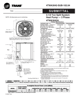
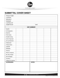
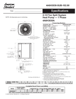
Specifications
Cooling equipment is selected based on numerous specifications
Type of refrigerant (R-22, R134a, R744, etc.)
Cooling Capacity
In the US, cooling capacity is often quantified in terms of Tons (e.g.10-500)
1 refrigeration ton = 1 TONScond = 12,000 BTU/h = 3,025.9 kCal/h = 12,661 kJ/h
Type of heat exchangers and flow capacity
Liquid vs air, and flow rates / pressure drops
Rated efficiency (COP = Useful energy/ costly energy… or EER = 3.413*COP)
Efficiency is rated at the factory under certain conditions on the heat
exchangers (input and output flow conditions)
Part load ratio performance
How the efficiency changes between idle and full blast


© Copyright 2026