
Ensemble Empirical Mode Decomposition Analysis of EEG Data
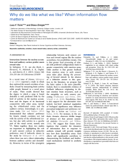
RESEARCH ARTICLE
Ensemble Empirical Mode Decomposition
Analysis of EEG Data Collected during a
Contour Integration Task
Karema Al-Subari1,2, Saad Al-Baddai1,2, Ana Maria Tomé3, Gregor Volberg4,
Rainer Hammwöhner2, Elmar W. Lang1*
a11111
1 Department of Biology, Institute of Biophysics, University of Regensburg, Regensburg, Germany,
2 Department of Linguistics, Literature and Culture, Institute of Information Science, University of
Regensburg, Regensburg, Germany, 3 Department of Electrical Engineering, Telecommunication and
Informatics, Institut of Electrical Engineering and Electronics, Universidade de Aveiro, Aveiro, Portugal,
4 Department of Psychology, Pedagogics and Sport, Institute of Experimental Psychology, University of
Regensburg, Regensburg, Germany
* [email protected]
Abstract
OPEN ACCESS
Citation: Al-Subari K, Al-Baddai S, Tomé AM,
Volberg G, Hammwöhner R, Lang EW (2015)
Ensemble Empirical Mode Decomposition Analysis of
EEG Data Collected during a Contour Integration
Task. PLoS ONE 10(4): e0119489. doi:10.1371/
journal.pone.0119489
Academic Editor: Manuel S. Malmierca, University
of Salamanca- Institute for Neuroscience of Castille
and Leon and Medical School, SPAIN
Received: September 26, 2014
Accepted: January 14, 2015
Published: April 24, 2015
Copyright: © 2015 Al-Subari et al. This is an open
access article distributed under the terms of the
Creative Commons Attribution License, which permits
unrestricted use, distribution, and reproduction in any
medium, provided the original author and source are
credited.
Data Availability Statement: Data is available at:
http://thedata.harvard.edu/dvn/dv/EEGDataset doi:10.
7910/DVN/28432.
Funding: DAAD (Acciones Conjuntas (Integradas)
Hispano-Alemanas). DAAD (Acções Integradas
Luso-Alemãs and FCT Cooperação Transnacional).
The funders had no role in study design, data
collection and analysis, decision to publish, or
preparation of the manuscript.
We discuss a data-driven analysis of EEG data recorded during a combined EEG/fMRI
study of visual processing during a contour integration task. The analysis is based on an ensemble empirical mode decomposition (EEMD) and discusses characteristic features of
event related modes (ERMs) resulting from the decomposition. We identify clear differences
in certain ERMs in response to contour vs noncontour Gabor stimuli mainly for response
amplitudes peaking around 100 [ms] (called P100) and 200 [ms] (called N200) after stimulus onset, respectively. We observe early P100 and N200 responses at electrodes located
in the occipital area of the brain, while late P100 and N200 responses appear at electrodes
located in frontal brain areas. Signals at electrodes in central brain areas show bimodal
early/late response signatures in certain ERMs. Head topographies clearly localize statistically significant response differences to both stimulus conditions. Our findings provide an independent proof of recent models which suggest that contour integration depends on
distributed network activity within the brain.
Introduction
The mammalian visual system is able to recognize a multitude of objects within a visual scene.
Object recognition presupposes the ability for contour integration and figure—ground separation. Visual integration is defined as the processes of combining the output of neurons, which
carry small attributes of a scene, into a complex structure more suitable for the guidance of behavior. Contour integration is one of the most elementary tasks during visual feature integration. Still it is debated whether contour integration is confined to the visual cortex or whether
higher brain areas are involved as well. The traditional theory of visual processing suggests a hierarchy of serial processing steps through a bottom-up cascade of discrete visual areas [1]. But
PLOS ONE | DOI:10.1371/journal.pone.0119489 April 24, 2015
1 / 27
EEMD Analysis of EEG during Contour Integration
Competing Interests: The authors have declared
that no competing interests exist.
this strict bottom—up processing is challenged by more recent theories proposing a parallel
bottom-up and top-down information flow [2]. The ability to integrate oriented contrast edges
(Gabor elements) into a contour depends on the spacing and orientation of the Gabor elements
relative to the path orientation [3, 4]. Similar principles apply in the multi-stable organization
of regular arrays of elements in rows and columns [5, 6]. Other, more general, stimulus properties also seem to influence the binding of contour elements: Closed contours are more easily detected than open ones [7, 8]. Likewise, symmetric contours are also easier to detect than
asymmetric ones [9]. Indeed, contour integration improves when Gabor elements are oriented
perpendicular to the contour within a closed area, and deteriorates, when these elements are
oriented parallel to the contour [10].
Event—related potentials and contour integration
Analyzing brain activities during visual processing is largely based on non-invasive techniques
like functional Magnetic Resonance Imaging (fMRI) and/or Electroencephalography (EEG). The
former offers good spatial resolution[11], while the latter excels in temporal resolution hence
finds applications also in brain—computer interfacing [12, 13]. Traditionally, EEGs are studied
at the level of event related potentials (ERPs) which represent averages over a sufficiently large
number of single trial recordings. Characteristic ERP components and their related latencies
are then compared for different stimulus conditions. Several studies investigate differences between contour and non-contour stimulus conditions for various components of event related
potentials (ERPs) [14, 15, 16, 17]. Such differences arise mostly for mean peak amplitudes of
the ERP components P1 and N1 denoting the first positive and first negative components appearing after stimulus onset, respectively. Early studies already demonstrated that modulations
during contour integration do not only vary with context but also with task demand [14]. This
study already shows that contour integration involves a neural network including anterior and
posterior brain areas in addition to the visual cortex. Recently, electrophysiological studies [15]
provided further clear evidence that context modulates the electrophysiological signature of
contour integration at early stages of visual processing. Modulating effects were mainly seen
for the ERP components N1 and P2, corresponding to the first negative and the second positive
ERP components appearing after stimulus onset. However, no effect was seen for the first positive ERP component P1. In summary, context primarily exerts a modulatory effect on the N1
component. These studies thus highlight the dynamic interplay between perceptual grouping
and the context in which it operates. A more recent contour integration study using EEG analysis [16] advocated the hypothesis that perceptual grouping involves top-down selection rather
than a mere pooling of afferent information streams encoding local elements in the visual field.
Differential brain activity, i. e. statistically significant differences in stimulus response amplitudes for the ERP component N1, occurring roughly at a latency of 170–180 [ms], could be detected only during a contour integration task within parietal, lateral occipital and primary
visual areas. If the contour stimuli were presented with a concurrent task (i.e., if the contours
were not the detection target), then no differences in brain activity were found between contour
and non-contour stimuli. The study concludes that contour integration seems to be based on
selecting information from primary visual areas, and appears to be controlled by the lateral occipital cortex. This conclusion corroborates results of another recent EEG study on contour integration [18]. A contour and a non-contour stimulus were presented within the same trial in
fast succession, with the task to indicate whether the contour was shown within the first or
within the second presentation interval. As a result, differences in brain activity between contour and non-contour stimuli occurred for stimuli shown in the first interval, but were
PLOS ONE | DOI:10.1371/journal.pone.0119489 April 24, 2015
2 / 27
EEMD Analysis of EEG during Contour Integration
completely absent for stimuli shown in the second interval. Thus, top-down information obtained from the serial presentation shaped the brain activity in response to contour stimuli.
The above mentioned debate about competing theories concerning the mechanisms of contour integration has been the focus of yet another electrophysiological study. Tackling the question whether serial facilitative interactions between collinear cells in the primary visual cortex
(V1) or pooling of inputs in higher-order visual areas determine contour integration, the authors applied high-density electrophysiological recordings to assess the spatio-temporal dynamics of brain activity in response to Gabor contour stimuli embedded in Gabor noise versus
control stimuli. The study concluded that the earliest effects could be observed in the ERP component N1 rather than in the component C1 of the visual evoked potential. Inverse modeling
identified sources in the lateral occipital complex (LOC) within the ventral visual stream as the
generators of N1 modifications. Also modulatory contextual effects appeared only at this later
processing period. The authors claim that these results are consistent with a pooling of information from primary visual areas in higher cortical areas only at a latency characteristic for the
occurrence of the N1 stimulus response component [19].
Concurrent to traditional ERP research, there is also increasing interest in oscillatory brain
responses during contour integration. Oscillatory brain activity is thought to reflect rhythmic
changes between relatively high and relatively low excitability within a neural population. By
synchronizing neural activity, groups of neurons can be transiently linked into neural assemblies to jointly process a given task [20]. With respect to contour integration, several studies revealed local power increases in beta frequencies (15–30Hz) during contour compared to noncontour processing. The beta power difference occurred relatively early (< 160 ms) and mostly
at parietal and occipital electrodes across studies [18, 21]. Furthermore, increased neural longrange synchronization has been observed during contour compared to non-contour processing
within theta (4–7 Hz) [22], alpha (8–12 Hz) [18] and beta frequencies [16]. Differences in
high-frequency (gamma) oscillations, sometimes assumed to be a correlate of conscious visual
perception [23], have not yet been found during contour integration. The results together show
that brain activity differences during contour and non-contour processing are not only reflected in the ERP amplitude, but also in neural oscillations within low-to-mid frequencies.
Technically, EEG and fMRI data sets can be recorded in separate sessions or simultaneously.
Integration of both, EEG and fMRI, recordings into one dataset for combined data analysis can
be performed either in a symmetrical or an asymmetrical way. The latter methods include
fMRI—directed EEG analysis and EEG-directed fMRI analysis [24]. Symmetrical data fusion
methods mainly resort to different variants of Independent Component Analysis (ICA). Simultaneously recording EEG and fMRI signals is a demanding technique in terms of data recording and signal processing. However, their combination can reveal both the location of active
brain areas and the temporal order of their activation. A very recent example is provided by a
study of the dynamics of contour integration in the human brain, where EEG and fMRI data
were acquired simultaneously during passively viewing Gabor stimuli under contour and noncontour conditions. By applying JointICA to the EEG and fMRI responses of the subjects, the
authors gained temporally and spatially highly resolved brain responses during contour integration which could not be derived from unimodal recordings. Within EEG recordings, they
found differences for stimuli with and without contours around 240 [ms] after stimulus onset,
in early visual (V1/V2) as well lateral occipital areas. Furthermore, they found an additional
later activity, occurring roughly at a delay of 300 [ms], in early visual areas for less salient contours, possibly reflecting re-entrant processing of such stimuli. Another combined EEG and
fMRI study revealed that contour detection depends on the information transfer between lateral occipital and parietal brain areas [22], where a good detection performance required a high
functional connectivity between these sites. Together these studies indicate that contour
PLOS ONE | DOI:10.1371/journal.pone.0119489 April 24, 2015
3 / 27
EEMD Analysis of EEG during Contour Integration
detection is accomplished within cortical networks, involving feedback loops between higher
and lower visual processing areas.
Signal decomposition techniques
Several signal decomposition techniques are available for a more detailed data analysis. Especially artifact removal, i. e. the extraction of signal components unrelated to cognitive brain activities, using blind signal separation techniques like principal and independent component
analysis (PCA, ICA) are standard techniques available in toolboxes like EEGLAB [25]. Such exploratory data analysis is hampered by the intrinsically non-stationary nature, and the non-linear couplings involved in signal generation. To help alleviate such issues, recently, an empirical
nonlinear analysis tool for complex, non-stationary temporal signal variations has been pioneered by N. E. Huang et al. [26]. Such technique is commonly referred to as Empirical Mode
Decomposition (EMD), and, if combined with Hilbert spectral analysis, it is called Hilbert—
Huang Transform (HHT). EMD utilizes empirical knowledge of oscillations intrinsic to a time
series in order to represent them as a superposition of components with well defined instantaneous frequencies. They adaptively and locally decompose any non-stationary signal in a sum
of Intrinsic Mode Functions (IMF) which represent zero-mean, amplitude- and (spatial-) frequency-modulated components. EMD represents a fully data-driven, unsupervised signal decomposition which does not need any a priori defined basis system. EMD also satisfies the
perfect reconstruction property, i.e. superimposing all extracted IMFs together with the residual slowly varying trend reconstructs the original signal without information loss or distortion.
Thus EMD lacks the scaling and permutation indeterminacy familiar from blind source separation (BSS) techniques. Because EMD operates on sequences of local extremes, and the decomposition is carried out by direct extraction of the local energy associated with the intrinsic time
scales of the signal itself, the method is thus similar to traditional Fourier or Wavelet decompositions. It differs from the wavelet-based multi-scale analysis, however, which characterizes the
scale of a signal event using pre-specified basis functions. Owing to this feature, EMD, and
even more so its noise-assisted variant called Ensemble Empirical Mode Decomposition
(EEMD), is a highly promising signal processing technique in dealing with problems of a
multi-scale nature. Note that with EMD a data representation as an expansion into intrinsic
modes is generated from the signal itself and no predefined basis system, as for example in
Wavelet decompositions, is used for the signal representation. Thus an EMD decomposition
reflects in a natural way the characteristics of non-stationary signals in either time or spatial
domains. Note further that Fourier transforms have constant frequencies and weights, while
Hilbert transforms allow the frequency as well as the amplitudes to vary over time.
In a recent study [27], we explored the potential of two-dimensional ensemble empirical
mode decomposition (2DEEMD) to extract characteristic textures, so-called bidimensional intrinsic mode functions (BIMFs), from the fMRI-related part of the current, combined EEGfMRI data sets which where taken while performing a contour integration task. To identify
most informative textures, i. e. BIMFs, a support vector machine (SVM) as well as a random
forest (RF) classifier were trained for two different stimulus/response conditions. Classification
performance was used to estimate the discriminative power of extracted BIMFs. The latter
were then analyzed according to their spatial distribution of brain activations related with contour integration. Results distinctly show the participation of higher brain areas, most notably
frontal fields, in contour integration.
Given the background disussed above, we suppose that EEMD is able to extract intrinsic signal modes, so-called event related modes (ERMs), which contain decisive information about
responses to contour and non-contour stimuli. Such ERMs should appear at various electrode
PLOS ONE | DOI:10.1371/journal.pone.0119489 April 24, 2015
4 / 27
EEMD Analysis of EEG during Contour Integration
locations indicating the presence of extended neuronal networks which process such stimuli.
We further hypothesize that such response signatures are better visible, with a high statistical
significance, in these modes rather than in the original recordings. Also any latencies related to
such signal components could be qunatified more precisely.
Outline of the paper
In the present study we concentrate on electrophysiological signatures within EEG recordings
of the above mentioned fMRI/EEG study. We again advocate the use of EEMD to investigate
neural correlates of contour integration via intrinsic modes extracted from the EEG signals, recorded while applying two visual Gabor stimulus conditions i. e. contour true (CT) and noncontour true (NCT), and studying the related electrophysiological response signals. The manuscript is organized as follows: Section Materials and Methods is devoted to a description of the
dataset available and the way, data has been acquired. In section Ensemble Empirical Mode Decomposition we provide a concise summary of an EEMD algorithm and give some necessary
details for its implementation. Section Results accounts for details of the EEG analysis and summarizes the main findings. It presents a detailed description of the EEMD analysis applied and
quantifies the results obtained. Component time courses and related head topographies further
illustrate these results. The last section offers a thorough discussion of these results.
Materials and Methods
Subjects
The subjects participating in the study encompassed 5 male and 13 female volunteers between
20–29 years old, i. e. (22.79 ± 2.7) [years]. All subjects were right-handed and had normal or
corrected-to-normal vision. Based on self-reports, the subjects had no neurological or psychiatric disorders, brain injuries or drug dependencies. This study also was approved by the local
ethics committee (study number 10-101-0035). Subjects were treated according to the principles laid down in the Helsinki declaration.
Gabor Stimuli
The stimuli were generated with a procedure similar to that of [28]. Stimulus displays contained odd symmetric Gabor elements arranged in an invisible 10 by 10 grid subtending 16.6
deg×16.6 deg of visual angle. The corresponding stimulus protocol is illustrated in Fig 1. The
luminance distribution L(x, y) of a single Gabor element is defined by the equation
Lðx; yÞ ¼ L0 ð1 þ sðx; yÞ gðx; yÞÞ
ð1Þ
where L(x, y) [cd/m2] is the luminance at point (x, y) and L0 is the background luminance. The
function s(x, y) represents a 2D—sinusoid, describing the carrier wave, and g(x, y) the related
Gaussian envelope, describing the amplitude modulation. These functions are given by
sðx; yÞ ¼ C sin ½kx x cos ðyÞ þ ky y sin ðyÞÞ
ð2Þ
where C = 0.9 is the Michelson contrast, k k = (kx, ky)T k [rad/m] = 2πf [cpd] is the angular
wave number with f = 3 [cpd] the corresponding spatial frequency in [cycles/deg], and θ is the
orientation from vertical which depends on the experimental condition. Furthermore,
2
x þ y2
ð3Þ
gðx; yÞ ¼ exp 2s2
PLOS ONE | DOI:10.1371/journal.pone.0119489 April 24, 2015
5 / 27
EEMD Analysis of EEG during Contour Integration
Fig 1. Gabor stimuli. The stimuli used in the present study.
doi:10.1371/journal.pone.0119489.g001
where σ = 0.25 deg is the standard deviation of the Gaussian envelope, measured in degrees of
visual angle.
For contour displays, a path of 10 invisible line segments was constructed and placed at a
random location within the stimulus area, with the restrictions that none of the segment centers, where the Gabor elements were finally placed, fell into the inner 2×2 grid cells, and that at
least 4 segment centers fell into the inner 6×6 grid cells. This ensured that the Gabor path did
not cross the central fixation mark, and that the eccentricity of the path was not too large. The
angle between adjacent line segments was the path angle α plus an orientation jitter Δα drawn
from a uniform distribution p(Δα) 2 [−1, +1]. Gabor elements were placed at the center of
each line segment and aligned to the segments orientation. The separation s between neighbouring elements depended on the length of the corresponding line segments. It was chosen as
α ± δα = 2 ± 0.55 degrees of visual angle. After setting up the Gabor path, empty grid cells were
filled with randomly oriented Gabor elements. The size of the grid cells was set to 2s=ð1 þ
pffiffiffi
2Þ ¼ 1:66 degrees of visual angle. This ensured that mean distance between distracting
Gabor elements was close to the mean distance between the elements making up the Gabor
path. The distracting Gabor elements were placed in the center of each grid cell and jittered
vertically and horizontally by ± 0.55 degrees of visual angle. New Gabor elements were not
drawn if their visible part overlapped with an already existing Gabor element by more than 5
pixels. The whole stimulus was withdrawn if more than 10 Gabor elements could not be
drawn. Thus, each stimulus contained 90–100 Gabor elements. For constructing non-contour
displays, the same algorithm was used as for the construction of contour displays but rotating
adjoining Gabor elements by ± 45 deg. Thus, non-contour displays resembled contour displays
with respect to spacing, positioning and the number of elements, but did not contain a
Gabor path.
For the experiment, a set of 150 non-contour stimuli was generated, which was the same for
all subjects. Then a set of 150 contour stimuli was generated separately for each subject, where
the path angle α was adjusted to the individual maximum tolerable path angle. These angles
were obtained during behavioral pre-testing and ranged from 21 deg ! 34 deg.
Experimental procedure
Subjects were positioned supine in the scanner. The visual stimuli were back projected onto a
translucent circular screen (LCD video projector, JVC DLA-G20, Yokohama, Japan) and was
PLOS ONE | DOI:10.1371/journal.pone.0119489 April 24, 2015
6 / 27
EEMD Analysis of EEG during Contour Integration
seen on a mirror reflecting the projected image. A standard PC running Presentation 12.0
(Neurobehavioral Systems Inc., Albany, Canada) was used for stimulus presentation. The projector had a resolution of 800 by 600 pixels at a refresh rate of 72 [Hz]. The viewing distance to
the projection screen was 64 [cm].
The trials started with the presentation of a central fixation cross that remained visible
throughout the experimental block. After a random interval from 1000–3000 [ms], a stimulus
was presented for 194 [ms], followed by a blank screen. The next trial started after the response,
or after a time-out of 3000 [ms] if the subject did not respond. The behavioral responses were
recorded with two fiber-optic response boxes (Lumitouch, Photon Control, Ltd, Burnaby, BC,
Canada) where one key was provided for each finger of the left and the right hand, respectively.
The subjects were instructed to detect contour stimuli. One half of the subjects used the left
hand for a contour response and the right hand for a non-contour response. For the other half
of the subjects the response mapping was reversed. Altogether, the subjects were presented
with 300 stimuli in a random order, partitioned into 15 blocks with 20 trials each.
Data acquisition
The EEG was recorded concurrently with fMRI in a Siemens Allegra 3 Tesla Head Scanner. In
this manuscript we focus on the EEG data. The fMRI results are reported in a separate work
[27].
The EEG was recorded with an MR-compatible 64 channel EEG system (BrainAmp MR
plus, Brain Products, Gilching, Germany). The scalp EEG was obtained from 62 equidistant
electrodes that were mounted in an elastic cap (EasyCap, Herrsching-Breitbrunn, Germany)
and were referenced to FCz during recording. Impedances were kept below 20 [kO]. The signals were amplified between 0.1100 [Hz], with a notch filter at 50 [Hz] in order to cancel out
mains hum. The sample rate was at the maximum resolution of 5000 [Hz]. To control for eyemovement artifacts, the vertical electrooculogram was recorded from an electrode placed
below the left eye. An electrocardiogram (ECG) electrode was placed below the left scapula in
order to facilitate the off-line removal of cardioballistic artifacts. The clock of the EEG amplifier
was synchronized with the clock output of the MR scanner using a SynchBox manufactured by
Brain Products (Gilching, Germany).
EEG Preprocessing
MR gradient switching produces large artifacts in the EEG each time a new slice is collected. A
second source of artifacts is the movement of electrodes and conductive blood inside the MR
scanner due to the cardiac cycle. The continuous EEG data were cleaned from both gradient
and cardioballistic artifacts by means of artifact template subtraction as implemented in the
FMRIB plug-in for EEGLAB [25, 29].
• Gradient artifact onsets were determined relative to the MR volume onset marker that was
recorded along with the EEG. With respect to gradient artifacts, a template was constructed
for each slice artifact and for each channel separately and then subtracted from the actual artifact. The template consisted of a moving average of 21 neighboring slices and a linear combination of the major principal components describing the residual artifacts that remain after
artifact subtraction. These were determined automatically by means of sorted eigenvalues.
The corrected data were down—sampled to 500 [samples/s] and highpass-filtered (FIR) at
0.5 [Hz]. Bad stretches of data in the continuous EEG, due to incomplete gradient artifact removal or other idiographic artifacts, were identified and removed by visual inspection.
PLOS ONE | DOI:10.1371/journal.pone.0119489 April 24, 2015
7 / 27
EEMD Analysis of EEG during Contour Integration
• Cardioballistic artifacts occur around heartbeats which show a characteristic deflection in the
ECG electrode denoted as QRS complex. The FMRIB plug-in provides a reliable algorithm
for the detection of QRS onsets. For removing cardioballistic artifacts, a temporal principal
component analysis (PCA) was performed on each EEG channel. The first three components
were taken as an optimal basis set for describing shape, amplitude and scale of the artifact.
This set was fit to, and then subtracted from, each artifact instance. As for the removal of gradient artifacts, this was performed for each channel separately.
Preprocessed EEG data subsequently were subjected to an independent components analysis (ICA) using the extended INFOMAX algorithm [30]. Components related to artifacts were
identified by visual inspection of the component topographies and power spectra. Main sources
of artifacts were eye blinks, eye movements, tonic muscle activity, as well as residual pulse and
gradient artifacts. Components identified as artifact-related were removed, and the remaining
components were back-projected into the EEG signal space. The data was then segmented into
intervals of 3 [s] duration, centered around the stimulus onset, and baseline-corrected within
the whole interval. Single trials were again inspected and rejected if they contained artifacts.
The overall rejection rate was between 6.7% and 42% across subjects (mean 22.5%), i. e., between 174–280 trials per subjects (on average 232.5 for both conditions) were available for
the analysis.
EEG data were analyzed using custom code and the EEGLAB toolbox developed at the
Swartz Center for Computational Neuroscience (SCCN), USA [25] (http://sccn.ucsd.edu/
eeglab/). For signal analysis, the segmented data were further reduced to intervals of 1000 [ms]
duration, each containing an onset of a Gabor stimulus. The epochs (trials) to be analyzed extended from t0−150 [ms] ! t0+850 [ms] relative to stimulus onset at t0, corresponding to
500 samples.
Hence, these single trial signals are denoted as
xðchÞ ðtn ; sÞ
with
n ¼ B; B þ 1; . . . 0; 1; . . . M 1;
ch ¼ 1; 2; . . . C
where ch denotes the index for the recording position (channel), s 2 SC = {CT, NCT} denotes
the stimulus condition and nt = 1, . . . Nt with Nt the total number of trials. The index tn is related to discrete time and t0 indicates the time of stimulus presentation, meaning that the segment
starts B = 75 samples before stimulus onset t0 and lasts more M = 425 samples.
In brain studies, evoked potentials are extracted from single trial recordings by averaging
single-trial signals, corresponding to a particular stimulus, over all trials. In this study, two different stimulus conditions, either contour true (CT) or non-contour true (NTC), were randomðchÞ
ðtn ; s 2 SCÞ were estimated
ly presented. Then, for each condition, average signals xavg
ðchÞ
xavg
ðtn ; s 2 SCÞ ¼
1 X ðchÞ
x ðtn ; sÞ
NSC s2SC
n ¼ B; B þ 1; . . . ; 0; . . . ; M 1
ðchÞ
ðchÞ
resulting, for each participant, in two sets of ERP signals xavg
ðtn ; CTÞ and xavg
ðtn ; NCTÞ using
NCT and NNCT trials, respectively.
Ensemble Empirical Mode Decomposition
Roughly a decade ago, an empirical nonlinear analysis tool for complex, non-stationary time
series has been pioneered by N. E. Huang et al. [26]. It is commonly referred to as Empirical
Mode Decomposition (EMD) and if combined with Hilbert spectral analysis it is called Hilbert
—Huang Transform (HHT). It can be applied to any non-stationary and also nonlinear data
set and represents a heuristic data decomposition technique which adaptively and locally
PLOS ONE | DOI:10.1371/journal.pone.0119489 April 24, 2015
8 / 27
EEMD Analysis of EEG during Contour Integration
decomposes any non-stationary time series in a sum of Intrinsic Mode Functions (IMF) which
represent zero-mean amplitude and frequency modulated components. The EMD represents a
fully data-driven, unsupervised signal decomposition and does not need any a priori defined
basis system. EMD also assures perfect reconstruction, i.e. superimposing all extracted IMFs
together with the residual trend reconstructs the original signal without information loss or
distortion. However, if only partial reconstruction is intended, it is not based on any optimality
criterion rather on a binary include or not include decision. The empirical nature of EMD offers
the advantage over other signal decomposition techniques like Exploratory Matrix Factorization (EMF) [31] of not being constrained by conditions which often only apply approximately.
Especially with biological signal processing, one often has only a rough idea about the underlying modes or component images, and frequently their number is unknown [32, 33]. In addition, perfect reconstruction is hampered by intrinsic scaling indeterminacies.
Eventually, the original signal x(t) can be expressed as
X
cðjÞ ðtÞ þ rðtÞ
xðtÞ ¼
j
c ðtÞ ¼
ðjÞ
Z
Refaj ðtÞ exp ðij ðtÞÞg ¼ Re aj ðtÞ exp i
t
1
0
oj ðt Þdt
ð4Þ
0
where the c(j)(t) represent the IMFs and r(t) the remaining non-oscillating trend. Furthermore,
R
aj(t) denotes a time-dependent amplitude, ϕj(t) = ωj(t)dt represents a time-dependent phase
d ðtÞ
and oj ½rad=s ¼ dtj denotes the related instantaneous frequency. Plotting both amplitude
aj(t) and phase ϕj(t) as a function of time for each extracted IMF represents a Hilbert—Huang
spectrogram [34].
During sifting, mode mixing as well as boundary artifacts can be avoided by a variant called
Ensemble Empirical Mode Decomposition (EEMD) which has been introduced by [35]. It represents a noise-assisted data analysis method. Fig 2 illustrates EEMD data processing in a flowchart diagram. First white noise of finite amplitude is added to the data, and then the EMD
algorithm is applied. This procedure is repeated many times, and the IMFs are calculated as an
ensemble average, consisting of the signal and added white noise. With a growing ensemble
number, the IMF converges to the true IMF [35]. Adding white noise to the data can be considered a physical experiment which is repeated many times. The added noise is treated as random
noise, which appears in the measurement. In this case, the n–th noisy observation will be
X
cðjÞ
xn ðtÞ ¼ xðtÞ þ n ðtÞ ¼
n ðtÞ þ rn ðtÞ;
ð5Þ
j
ðjÞ
where x(t) is the true signal, n(t) is the random noise and cðjÞ
n ¼ c þ n ðtÞ represents the IMF
obtained for the n-th noise observation. Therefore the resultant IMF c(j) is obtained by averaging all the cðjÞ
n of the ensemble. The flowchart, Fig 2, summarizes the main steps of the EEMD
algorithm where the shifting process was implemented with a fixed number iterations instead
of verifying the IMF condition [32]. Additionally, EEMD needs to prescribe two parameters,
namely the size E of the ensemble and the standard deviation σnoise of added Gaussian noise.
Those two parameters were chosen empirically after several attempts which indicated an optimal ensemble number E = 20 and a proper standard deviation σnoise = 0.2σsignal, where σsignal
denotes the standard deviation of the signal amplitude distribution. Furthermore, because of
the need to average corresponding IMFs over several trials, the number of IMFs into which the
signals are decomposed has been fixed in advance. Empirically, after systematically varying the
number of modes, a decomposition into 7 IMFs plus a residuum was considered most
PLOS ONE | DOI:10.1371/journal.pone.0119489 April 24, 2015
9 / 27
EEMD Analysis of EEG during Contour Integration
Fig 2. Flowchart diagram of the EEMD algorithm. The parameters were assigned according to values used in the numerical simulations.
doi:10.1371/journal.pone.0119489.g002
PLOS ONE | DOI:10.1371/journal.pone.0119489 April 24, 2015
10 / 27
EEMD Analysis of EEG during Contour Integration
appropriate. Slightly abusing the definition of a residuum, by integrating the latter as an additional IMF, all signals were decomposed into 8 IMFs finally.
Results
The following section will present results obtained from an EEMD analysis of EEG recordings
of 18 subjects during a contour integration task. EEG data have been recorded simultaneously
with fMRI scans. The evaluation of the latter has been reported recently by [27]. Results concerning raw data are presented at the level of event -related potentials (ERPs). Data is then decomposed with EEMD either using single trial recordings or ERPs.
Illustrations of raw data characteristics
Grand average ERPs. Responses to Gabor stimuli exhibited a large biological variability as
can be seen from Fig 3. There, for the purpose of illustration only, global ERPs are shown of all
Fig 3. Global averages of individual ERPs elicited by the two stimulus conditions CT and NCT. The ERP amplitudes are normalized to zero mean and
unitary standard deviation. ERPs for both conditions are superimposed onto each other, blue: Contour condition and green: Non-contour condition.
doi:10.1371/journal.pone.0119489.g003
PLOS ONE | DOI:10.1371/journal.pone.0119489 April 24, 2015
11 / 27
EEMD Analysis of EEG during Contour Integration
Fig 4. Grand average ERPs. They result from averaging individual global ERPs from 18 subjects.
doi:10.1371/journal.pone.0119489.g004
subjects as averages over all channels. Such global averages provide a rough idea about the extent of biological variability between individual stimulus responses. Fig 4 illustrates a typical
global ERP response, obtained as a grand average over all channels and over all subjects. Such a
grand average ERP exhibits four prominent ERP peaks after stimulus onset, which will be denoted according their latencies as P100, N200, P300 and N400, respectively [36]. As can be
seen, typically one observes a positive peak occurring roughly at 100 [ms] (maximal response
amplitude usually occurring between 70 [ms] and 180 [ms]) after stimulus onset, called P100.
This is followed by a negative peak, called N200, with maximal amplitude between 150 [ms]
and 260 [ms]). P300 identifies the next positive peak occurring usually between 270 [ms] and
370 [ms], followed by a late negative potential, denoted N400, at 370 [ms] to 450 [ms]. Note
that the Gabor stimuli last for almost Δtst = 200 [ms] after stimulus onset t0, hence encompasses
P100 and part of N200.
Individual ERPs. In the grand average ERP, differences between stimulus conditions
mostly appear for the early responses, i. e. for P100 and most notably for N200, N400, and
seemingly also between 600 [ms] and 800 [ms]. Mean amplitudes have been estimated therefore within intervals centered at these characteristic peaks. By visual inspection, it can be seen
that for the ERP P100, in the occipital brain area an early response occurs during the time interval 60 [ms]–120 [ms] while in the frontal brain area the corresponding P100 peak shows up
in the interval 120 [ms]–180 [ms]. Correspondingly, for the ERP N200 two intervals were considered corresponding to an early response at 150 [ms]–210 [ms] and a late response at 200
[ms]–260 [ms], respectively. Next, the difference of the absolute values of these mean response
amplitudes, estimated at each channel and for each stimulus condition, has been computed. Finally, these differences have been averaged over the population of 18 subjects. A paired t-test
identified the channels with the most significant differences in signal responses. The resulting
PLOS ONE | DOI:10.1371/journal.pone.0119489 April 24, 2015
12 / 27
EEMD Analysis of EEG during Contour Integration
Fig 5. Head topography of the significant difference of the P100 signals. Top: Early response, Bottom: Late response
doi:10.1371/journal.pone.0119489.g005
values have been used to generate corresponding head topographies as illustrated in Figs 5
and 6. The topograms (see Fig 5) illustrate early and late response differences resulting from
mean response amplitudes around the ERP P100. Obviously, early as well as late response differences appear to be insignificant at a confidence level of α = 0.05. On the contrary, early and
late response differences estimated around the ERP N200 (see Fig 6) appear to be significant
for the same confidence level. Early response differences are located in occipital areas of the
brain, while late responses are found in frontal brain areas only. Additionally, such significant
differences are detected only in the right hemisphere. Table 1 summarizes p—and T—values
for significant early and late responses at various locations (channels) and for different confidence levels in case of ERP N200.
Fig 6. Head topography of the significant difference of the N200 signals. Top: Early response, Bottom: Late response
doi:10.1371/journal.pone.0119489.g006
PLOS ONE | DOI:10.1371/journal.pone.0119489 April 24, 2015
13 / 27
EEMD Analysis of EEG during Contour Integration
Table 1. Test statistics for ERP N200. Results of statistical tests of differences in mean ERP amplitudes for the event related potential N200 in early and
late response areas. P- and T-values are reported for different significance levels: (*):α = 0.05, (**):α = 0.01, (***):α = 0.001
Early response
p-value
T-value
Late response
Channel
p-value
T-value
Channel
0.042*
-2.199
C4
0.003**
3.417
AF4
0.015*
-2.720
CP6
0.022*
2.511
F6
0.012*
-2.830
CP4
0.005**
-3.255
AF7
0.023*
2.500
AF8
doi:10.1371/journal.pone.0119489.t001
Event-related modes from EEMD decomposition
A more informative way to analyze ERPs concerns the application of signal decomposition
techniques which offer a principled way of extracting characteristic features from the recordings which reveal significant response differences between both stimulus conditions. In this
study, EEG signals are decomposed by applying ensemble empirical mode decomposition
(EEMD). The latter will be applied to the set of signals in two different ways. Approach A preserves phase-locked modes and disregards non-phase-locked modes, while approach B considers both, phase-locked as well as non-phase-locked, modes during mode decomposition:
(A) After averaging over trials, EEMD is applied to all single channel ERPs, i. e. to
ðchÞ
xðchÞ
avg ðtn ; CT Þ and xavg ðtn ; NCT Þ, respectively, thus yielding event-related modes (ERMs)
which contain only those parts of the response signals that are phase-locked to
the stimuli.
(B) Alternatively, EEMD is applied to each single trial response signal x(ch)(tn, s) at each channel separately. Then all corresponding IMFs become, for each of the two stimulus conditions, averaged over all trials to yield related ERMs. The latter now also contain
information about signal components non-phase-locked to the stimuli.
Before applying an EEMD decomposition, all signals were standardized to zero mean and
unit variance (z-score).
Approach A: EEMD after averaging over trials. The following Fig 7 illustrates ERMs, obtained from a grand average of global ERPs as shown in Fig 4, and their related Hilbert—
Huang—Transforms. Especially ERM3–ERM6 show rather pronounced oscillations with stable
frequencies (see the related Hilbert—Huang Transforms) ranging from 3 [Hz]–30 [Hz] roughly. Thus these oscillations represent characteristic EEG bands like theta—or alpha—bands.
Averaging has been performed for each stimulus condition separately and EEMD decomposition was performed for each ERP signal. Then IMF (ERM) amplitudes have been estimated
within intervals centered at the characteristic peaks of the corresponding ERMs, i. e. for P100,
N200 etc. as was explained above. Again, a subsequent paired t-test identified the channels
with the most significant differences in signal responses. The resulting values have been used to
generate corresponding head topographies. The latter are very similar to the ones obtained by
approach B, but show lower significance levels. These results are summarized in Table 2 and
Table 3. As can be seen from Table 2, early responses have been observed only for channels located in the occipital and parietal areas of the brain, while a highly significant late response has
been observed for a channel in the frontal area of the brain. A similar observation holds for the
entries of Table 3. Significant early response differences are more numerous for the different
N200 ERM components, while again only a single frontal channel exhibited a significant
PLOS ONE | DOI:10.1371/journal.pone.0119489 April 24, 2015
14 / 27
EEMD Analysis of EEG during Contour Integration
Fig 7. EEMD decomposition on grand average ERPs. Single subject ERPs were averaged over 18 subjects and are shown for two stimulus conditions:
Contour and Non-contour. This signal is generated by averaging all signals from Fig 3 for the two conditions separately. Plots in the left column represent the
averaged signal (on top) followed by its event-related intrinsic modes (ERMs). Plots in the right column present related Hilbert spectra for each of the
corresponding ERMs in the left column.
doi:10.1371/journal.pone.0119489.g007
response difference. Note that even the original ERP shows significant late response differences
for the N200 ERP component.
Approach B: EEMD before averaging over trials. Approach B consisted in performing
an EEMD of all single trial signals separately. Then an average over trials has been performed
for each IMF, each stimulus condition and each channel, resulting in corresponding ERMs.
The further analysis estimating mean peak amplitudes of ERM components has been done in
the same way as already discussed for approach A.
PLOS ONE | DOI:10.1371/journal.pone.0119489 April 24, 2015
15 / 27
EEMD Analysis of EEG during Contour Integration
Table 2. Approach A: Test statistics for ERM4 and ERM5 from P100. The table summarizes parameters of the test statistics (p-value, T-value) for ERM4
and ERM5 extracted from the ERP P100. An EEMD has been applied after averaging over trials to extract ERMs. P- and T-values are given for different confidence levels: (*):α = 0.05, (**):α = 0.01.
Early response
Late response
ERM
p-value
T-value
Channel
ERM 4
0.046*
-2.155
C6
ERM 5
0.009**
-2.969
P8
0.025*
-2.460
CP6
0.036*
-2.276
P6
p-value
T-value
Channel
0.002**
3.747
F4
doi:10.1371/journal.pone.0119489.t002
Fig 8 illustrates differences in early P100 responses for both stimulus conditions. The top
row presents on the right the component ERM5 for both stimulus conditions. It represents an
average over all channels which exhibit a significant response difference at a confidence level of
α = 0.05. On the left, the corresponding raw signal is presented for comparison. In the component ERM5, clear differences are seen in response amplitude for both stimulus conditions. In
the bottom row, the topography resulting from differences in ERM5 amplitudes related to the
ERP P100 at a significance level of α = 0.05 is shown. The rightmost topogram exhibits those
brain regions where significant signal differences could be detected. As can be seen, early responses are localized in occipital and parietal areas of the right brain hemisphere only. There,
the amplitude of the P100 component of ERM5 is larger for the stimulus condition NCT than
for condition CT (see Fig 8). Furthermore, remember that for the raw P100 ERPs (Fig 8, top
left) no statistically significant differences in response amplitude could be found. Note that the
P100 peak maximum, both in the raw signal as well as in the ERM5, occurs shortly before
t = 100 [ms], hence represents what we call an early stimulus response.
Fig 9 illustrates differences in what we call late P100 responses for both stimulus conditions.
The top row presents to the right the component ERM5 for both stimulus conditions. It represents an average over all channels which exhibit a significant response difference at a confidence level of α = 0.05. On the left, the corresponding raw signal is presented for comparison.
Table 3. Approach A: Test statistics for ERM5, ERM6 and ERM7 from N200. The table summarizes parameters of the test statistics for ERM5, ERM6 and
ERM7 extracted from the N200 ERP. An EEMD has been applied after averaging over trials to extract ERMs. P- and T-values are given for different confidence levels: (*):α = 0.05, (**):α = 0.01.
Early response
Late response
ERM
p-value
T-value
Channel
p-value
T-value
Channel
ERM 5
0.010*
-2.884
P4
0.026*
2.438
F4
0.008**
-3.034
P8
0.003**
-3.552
CP6
0.013*
-2.784
CP4
0.015*
-2.693
P6
ERM 6
0.040*
-2.226
CP6
0.047*
-2.141
ERM 7
0.008**
2.998
O1
0.002**
3.613
P7
CP3
doi:10.1371/journal.pone.0119489.t003
PLOS ONE | DOI:10.1371/journal.pone.0119489 April 24, 2015
16 / 27
EEMD Analysis of EEG during Contour Integration
Fig 8. Early stimulus response at ERP P100. Top Left: Standardized original ERPs for both stimulus conditions. Top Right: ERM5 for both stimulus
conditions. Bottom: Head topographies showing locations of significant differences in ERM5 amplitudes for both stimulus conditions.
doi:10.1371/journal.pone.0119489.g008
Fig 9. Late stimulus response at ERP P100. Top Left: Standardized original ERPs for both stimulus conditions. Top Right: ERM5 for both stimulus
conditions. Bottom: Head topographies showing locations of significant differences in ERM5 amplitudes for both stimulus conditions.
doi:10.1371/journal.pone.0119489.g009
PLOS ONE | DOI:10.1371/journal.pone.0119489 April 24, 2015
17 / 27
EEMD Analysis of EEG during Contour Integration
In the component ERM5, the differences in response amplitude for both stimulus conditions
are even more pronounced than in case of the early response. On the left, an average of the raw
signals of all those channels which exhibit significant response differences is shown. In the bottom row the topography resulting from differences in ERM5 amplitudes measured for the ERP
P100 at a significance level of α = 0.05. The rightmost topogram exhibits those brain regions
where significant signal differences could be detected. As can be seen, late responses are localized in frontal and medio-temporal areas in the right hemisphere only. There the ERM5 amplitude for the stimulus condition CT is larger than for condition NCT (see Fig 9) contrary to
what has been observed for the early P100 response in occipital areas. Note that the peak maximum occurs roughly at t ’ 150 [ms]. Again for the raw P100 ERP signal no statistically significant differences between both stimulus conditions could be found. Table 4 summarizes, for
approach B and the P100 ERP, parameters (p- and T-values) of the test statistics for ERM4 and
ERM5 at different confidence levels. Note that an early response has been observed only for
channels located in the occipital and parietal areas of the brain, while a late response is observed for a channel in the frontal area of the brain.
Fig 10 illustrates differences in early N200 responses for both stimulus conditions. The top
row presents on the right the component ERM5 for both stimulus conditions. It represents an
average over all channels which exhibit a significant response difference at a confidence level of
α = 0.05. On the left, the corresponding raw signal is presented for comparison. In the component ERM5, differences in response amplitude for both stimulus conditions are seen clearly.
On the left, an average of the raw signals of all those channels which exhibit significant response differences is shown. The bottom row shows the topography resulting from differences
in ERM5 amplitudes measured for the ERP N200 at a significance level of α = 0.05. The rightmost topogram exhibits those brain regions where significant signal differences could be detected. As can be seen, early responses are localized in occipital and parietal areas in the right
hemisphere mainly but also in the left hemisphere, contrary to the P100 response. In the indicated brain areas, the ERM5 amplitude for the stimulus condition NCT is again larger than for
condition CT (see Fig 10). Note that the negative peak occurs shortly before t = 200 [ms] and
exhibits a clear shoulder shortly after t = 200 [ms].
Table 4. Approach B: Test statistics for ERM4 and ERM5 from P100. The table summarizes parameters of the test statistics (p-value, T-value) for ERM4
and ERM5 extracted from the ERP P100. An EEMD has been applied before averaging over trials. P- and T-values are given for different confidence levels:
(*):α = 0.05, (**):α = 0.01, (***):α = 0.001.
Early response
ERM
ERM 4
ERM 5
p-value
T-value
Late response
Channel
p-value
T-value
Channel
F3
0.015*
-2.705
O2
0.025*
2.464
0.038*
-2.256
CP6
0.015*
2.695
F5
0.004**
-3.329
C4
0.006**
3.124
FC6
0.009**
-2.902
P4
0.031*
2.354
AF4
0.009**
-2.906
P8
0.000***
-4.384
CP6
0.000***
-5.311
CP4
0.031*
-2.345
PO4
0.049*
-2.123
C6
0.027*
-2.416
P6
doi:10.1371/journal.pone.0119489.t004
PLOS ONE | DOI:10.1371/journal.pone.0119489 April 24, 2015
18 / 27
EEMD Analysis of EEG during Contour Integration
Fig 10. Early stimulus response at ERP N200. Top Left: Standardized original ERPs for both stimulus conditions. Top Right: ERM5 for both stimulus
conditions. Bottom: Head topographies showing locations of significant differences in ERM5 amplitudes for both stimulus conditions.
doi:10.1371/journal.pone.0119489.g010
Fig 11 illustrates differences in late N200 responses for both stimulus conditions. The top
row presents on the right the component ERM5 for both stimulus conditions. It represents an
average over all channels which exhibit a significant response difference at a confidence level of
α = 0.05. On the left, the corresponding raw signal is presented for comparison. In the component ERM5, again very pronounced differences are seen in response amplitude for both stimulus conditions. The bottom row shows the topography resulting from differences in ERM5
amplitudes measured for the ERP N200 at a significance level of α = 0.05. The rightmost topogram exhibits those brain regions where significant signal differences could be detected. As can
be seen, late responses are localized in frontal and medio-temporal areas in the right hemisphere only. There the ERM5 amplitude for the stimulus condition CT is again larger than for
condition NCT. Note that for the late response the negative peak occurs shortly after t = 200
[ms]. Table 5 summarizes, for approach B and the N200 ERP component, parameters (p- and
T-values) of the test statistics for ERM5–ERM7 at different confidence levels. Early responses
were obtained again from channels in the occipital and parietal regions of the brain, while late
responses were located at channels in frontal regions. Note that the difference between early
and late responses is most clearly shown in ERM5.
The ERM5 is the mode that consistently has peaks with latencies similar to the studied ERP
components. Concerning the component P100 of the mode ERM5, an early response is manifest on electrodes located in the occipital and parietal brain areas with a stronger response amplitude for the NCT—stimulus condition. On the contrary, a late P100 response is clearly
detected in frontal brain areas with a larger response amplitude for the CT—stimulus condition. The delay of the late P100 response component amounts to Δt 70 [ms]±10 [ms]. Furthermore, the response differences appear much more pronounced for the late P100 response
compared to the early P100. A remarkable detail is seen in the P100 response for the NCT—
PLOS ONE | DOI:10.1371/journal.pone.0119489 April 24, 2015
19 / 27
EEMD Analysis of EEG during Contour Integration
Fig 11. Late stimulus response at ERP N200. Top Left: Standardized original ERPs for both stimulus conditions. Top Right: ERM5 for both stimulus
conditions. Bottom: Head topographies showing locations of significant differences in ERM5 amplitudes for both stimulus conditions.
doi:10.1371/journal.pone.0119489.g011
stimulus condition. The P100 peak corresponding to the NCT—condition, which is visible in
the early response (see Fig 8, top right), splits in the late response (see Fig 9, bottom right) into
a double peak with one component at a time of occurrence of the early P100 response, and a
later P100 response, peaking roughly 70 [ms] after the early response. This detail is only visible
for the stimulus condition NCT and is absent for the CT—stimulus. The latter only shows the
delayed component. Related head topographies indicate the brain areas where statistically significant response differences could be detected. They consistently indicate such differences
only for the right hemisphere in broad agreement with recent findings about a right hemisphere specialization of contour integration [37]. They appear more focused in frontal areas
while they are more diffuse and spatially extended in occipital, parietal and parieto-temporal
areas for the early responses. Clearly, occipital as well as frontal areas are involved in contour
integration as early as for the P100 response but most notably at the N200 level. This seems to
support assertions of a top-down control in contour integration [18].
Similar results are obtained for the N200 response. An early N200 response prominently appears before t = 200 [ms], while a late N200 response is peaking after t = 200 [ms]. The response
amplitude in the early phase is again larger, i. e. more negative, for the NCT—stimulus condition, while it is weaker in the late phase of the response. Once again, the response difference is
more pronounced for the late response. Remarkably, the N200 response contour for the early
CT—stimulus response exhibits a shoulder at the time where the late N200 response amplitude
peaks. However, no clear double peak structure appears as for the P100 CT—stimulus response. If one compares the ERM5 signal structure related to the different electrodes located
on a path from occipital to frontal a clear shift in the time of occurrence of the N200 peak from
early to late is seen. Thus single ERMs allow to follow a precise timing of the N200 ERP along
the visual processing pathway.
PLOS ONE | DOI:10.1371/journal.pone.0119489 April 24, 2015
20 / 27
EEMD Analysis of EEG during Contour Integration
Table 5. Approach B: Test statistics for ERM5, ERM6 and ERM7 from N200. The table summarizes parameters of the test statistics for ERM5, ERM6 and
ERM7 extracted from the ERP N200. An EEMD has been applied before averaging over trials. P- and T-values are given for different confidence levels: *−α
= 0.05, **−α = 0.01.
Early response
ERM
ERM 5
ERM 6
ERM 7
Late response
p-value
T-value
Channel
p-value
T-value
Channel
0.001***
-4.148
P4
0.040*
2.222
F4
0.009**
-2.927
O2
0.014*
2.753
F8
0.004**
-3.359
P8
0.015*
2.692
FC6
0.003**
-3.470
CP6
0.039*
2.235
AF4
0.005**
-3.225
CP4
0.048*
2.132
F6
0.003**
-3.541
PO4
0.033*
2.329
AF8
0.026*
-2.442
C5
0.003**
-3.440
P6
0.003**
-3.465
PO8
0.032*
-2.339
C3
0.005**
-3.257
F8
0.009**
-2.931
P7
0.008**
-2.991
FC4
0.014*
-2.725
CP5
0.029*
-2.387
CP4
0.006**
-3.114
PO3
0.033*
-2.321
P5
0.036*
-2.275
P6
0.033*
-2.327
PO7
0.030*
2.374
P3
0.042*
2.204
FC5
0.010*
2.891
P4
0.014*
2.753
O1
0.046*
2.155
O2
0.014*
2.753
CP5
0.008**
2.981
PO3
0.022*
2.533
P5
0.002**
3.657
PO7
doi:10.1371/journal.pone.0119489.t005
Discussion
In the study we presented EEG recordings from 18 subjects which were participating in a perceptual learning task. More specifically, subjects were presented with Gabor stimuli which occasionally formed an open continuous contour. Subjects were asked to indicate the presence
(CT) or absence (NCT) of such contours in their visual field at certain time points. After proper
pre-processing, raw data have been averaged over all trials to extract event related potentials
(ERPs) at every electrode. A global average of such ERPs is illustrated for all 18 subjects in Fig
3. Clearly, there is a large biological variability in the data with mostly little difference between
both stimulus conditions. Note that data have been individually standardized to zero mean and
unit variance. Relative differences between both stimulus conditions have been preserved that
way. Fig 4 presents a grand average of individual global ERPs, indicating most clearly four
prominent peaks named P100, N200, P300 and N400. This grand average suggests that differences in response amplitudes between both stimulus conditions are most probably to be expected at the early ERPs, i. e. at P100 and N200. But a statistical testing of observed differences
in response amplitudes to both stimulus conditions could not proof any significant difference
PLOS ONE | DOI:10.1371/journal.pone.0119489 April 24, 2015
21 / 27
EEMD Analysis of EEG during Contour Integration
in the P100 ERP amplitudes at a significance level of α = 0.05 corresponding to T 2.1 (see Fig
5). For the N200 ERP response amplitudes, at the same significance level, statistically significant differences could be found at several electrodes mainly located in the occipital and parietal
areas of the brain but also in frontal brain areas. Interestingly, response amplitudes peaked before t = 200 [ms] in the occipital and parietal areas but showed a late response after t = 200 [ms]
for the frontal electrodes. Henceforth, these response are called early and late responses, respectively. Early and late responses show a delay of roughly Δt = 100 [ms] and correlate well with
electrode locations in either the occipital or frontal brain areas.
This rough analysis of raw ERP signals has been improved by applying a signal decomposition technique based on an ensemble empirical mode decomposition (EEMD) as proposed by
Huang et al. [26, 35, 38]. The analysis has been performed in two different ways: either EEMD
has been applied before or after averaging over trials. The resulting component signals extracted have been called event related modes (ERMs). EEMD before averaging delivered better
results with respect to statistical measures, probably because of unfavorable signal compensations through averaging. Hence, only these results have been presented in detail. For illustrative
purposes only, Fig 7 presents a grand average EEG signal extending from 150 [ms] before stimulus onset at t0 = 0 to 850 [ms] after t0. While the original signals exhibit only small differences,
mainly around ERP N200, some of the extracted ERMs indicate clear differences between both
stimulus conditions. The related Hilbert—Huang spectra indicate decent regularities in these
ERMs with characteristic frequencies which stay largely constant over the time span considered. Most notable differences are seen for ERM3, ERM4, ERM5 and ERM6. For example,
ERM3 shows a dominant frequency around ν = 25 [Hz], corresponding to the β—band, ERM4
shows oscillations around ν = 10 [Hz] which represents an α—activity, ERM5 oscillates with
roughly ν = 5 [Hz] indicating a θ—wave and, finally, ERM6 is dominated by an oscillation with
ν 2 [Hz] corresponding to a δ—wave. ERM2 is indicative of some high frequency (ν 30
[Hz]) activity which might contain γ—wave activities. Note that these spectral characteristics
agree between both stimulus conditions.
Even further insight is provided from ERMs resulting from an EEMD application to the single trial signals. The resulting intrinsic mode functions (IMFs) have then been averaged over all
trials to result in corresponding ERMs. The largest differences between stimulus conditions are
seen for ERM4–ERM6, i. e. in the α−, θ− and δ—bands, around P100 and N200. A general
characteristic of the ERP components is that a clear transition from an early response to a late
response is observable which exhibits a strong correlation to a spatial representation of the
stimulus response either in the occipital or the frontal brain areas. Central brain areas show
signs of both, early and late responses. The electrodes, where either the early or the late response could be observed, are shown in Fig 12.
While studying the switching between early and late responses in more detail, signals have
been pooled according to a clustering scheme proposed by [39] which divides each hemisphere
into six electrode clusters. The grouping of electrodes on the right hemisphere is given in table
of the Fig 12. The difference on the latency of the peaks of ERM5 related with the ERP components is clearly visible on the ERM averages of the pooled electrodes. Fig 13 illustrates that
those peaks show earlier in the parietal -occipital regions (OC, P, PT) and later on the frontal
(FR, AT). The differences in latencies of ERM5, corresponding to the pooled signals of the right
hemisphere, are marked in Fig 13 by the straight lines. Similar differences are observed in the
left hemisphere though supported by a smaller statistical significance between the conditiond
(see Tables 4 and 5). However, the ERM5 of the CE cluster clearly exhibits a double peak structure of the N200 ERP component showing early and late response components simultaneously.
This is justified by the average of the two kind of signals, e.g, early and late responses.
PLOS ONE | DOI:10.1371/journal.pone.0119489 April 24, 2015
22 / 27
EEMD Analysis of EEG during Contour Integration
Fig 12. Pooling of electrodes into 6 clusters and the electrocap layout. Left: Notation refers to the right
hemisphere. The left hemisphere is organized similarly with the electrodes with odd number.Right: It shows
the two groups of electrodes related with early and late responses
doi:10.1371/journal.pone.0119489.g012
Surprisingly, the pooled ERM5 of the frontal region shows a similar double peak structure for
the ERP component P100.
Because the human head is a volume conductor, the peaks in the ERP and ERM amplitudes
observed at frontal and occipital electrodes do not necessarily imply that the brain activity was
generated within frontal and occipital sources, respectively. However, a change in topography
as seen from the earlier to the later phases of the P100 and N200 peaks clearly indicates different distributions of neural activity in each phase [40, 41]. Thus, the data favor the view that
contour processing involves activity within distributed brain networks, rather than focal activity within the lower visual cortex [42]. This notion is broadly compatible with results from recent EEG or combined EEG and fMRI investigations [16, 17, 22]. On contrast to previous
studies, we used a data-driven approach for EEG signal decomposition. The findings thus give
an independent proof that contour integration depends on distributed network activity.
The time and frequency ranges where differences between stimulus conditions occurred are
comparable to those of previous studies on oscillatory brain responses during contour integration. We found the strongest differences at parietal and occipital sites occurring < 200ms after
stimulus onset and in low-to-mid frequencies [16, 18, 21]. A prominent role for beta oscillations in contour integration, as observed in our previous studies, did not show up in the data.
Note, however, that a transient increase in beta power would not necessarily lead to increased
amplitudes within one specific ERM. An ERM-based analysis or the EEG is thus not well-suited for validating the results of previous Fourier-based analyses.
In this study we used exclusively Gabor arrays as visual stimuli. It could thus be objected
that the results are not specific for contour integration, but reflect some general visual processes
under conditions of low stimulus visibility. Indeed, a recent fMRI study revealed that brain activity in visual as well a prefrontal areas increased with the presentation duration and so with
the visibility of shortly presented gratings [43]. The role of the frontal cortex in this and in our
study is yet unclear. Previous authors argue that frontal cortical activity is related to a conscious
visual experience or to post-perceptual processes like motor preparation [44, 45]. On the other
hand, the frontal cortex can also be directly involved into the actual stimulus processing [43].
PLOS ONE | DOI:10.1371/journal.pone.0119489 April 24, 2015
23 / 27
EEMD Analysis of EEG during Contour Integration
Fig 13. The pooled ERM5 responses. The ERM5 are averaged in pools of electrodes located on different regions.
doi:10.1371/journal.pone.0119489.g013
The fact that posterior and frontal activity differences between contour and non-contour conditions occurred very early during processing is more in line with the latter interpretation.
Thus, it seems warranted to conclude that the observed differences in brain activity originate
from contour processing per se.
Conclusion
In this investigation we used a data-driven approach to analyze EEG time series recorded during a contour integration task employing Gabor stimulus patterns. An EEMD analysis allows
to extract component signals which show differences between stimulus conditions with clear
PLOS ONE | DOI:10.1371/journal.pone.0119489 April 24, 2015
24 / 27
EEMD Analysis of EEG during Contour Integration
statistical significance. Most notably ERM5 exhibits very pronounced differences between contour and non-contour stimulus responses. From an approach employing pooled electrode signals, latencies between early and late responses can be identified and quantified whereby early
responses are registered at electrodes in the posterior part of the scalp, while late responses are
visible only in the frontal part of the scalp. The pool of electrodes in the central part of the
brain even exhibits both early and late responses in pronounced double peak structures. Together these findings provide independent evidence of a view of extended neuronal networks
involved in visual processing, especially contour integration. Future work will concentrate on
identifying related sources of neuronal activation via inverse modeling. The software tools developed within this study have been integrated into a toolbox EMDLAB which will be provided
as a plug-in to the EEGLAB toolbox available at http://sccn.ucsd.edu/eeglab/.
Author Contributions
Conceived and designed the experiments: GV. Performed the experiments: GV. Analyzed the
data: KAS SAB AMT EWL. Contributed reagents/materials/analysis tools: KAS SAB AMT
EWL. Wrote the paper: EWL AMT GV RH. Discussion of data analysis and results: RH GV.
References
1.
Felleman DJ, van Essen DC. Distributed hierarchical processing in the primate cerebral cortex. Cereb
Cortex. 1991; 1:1–47. doi: 10.1093/cercor/1.1.1 PMID: 1822724
2.
Lamme VAF, Roelfsma PR. The distinct modes of vision offered by feedforward and recurrent processing. Trends Neurosci. 2000; 23:571–579. doi: 10.1016/S0166-2236(00)01657-X PMID: 11074267
3.
Field DJ, Hayes A, Hess RF. Contour integration by the human visual system: evidence for a local “association field”. Vision Res. 1993; 33(2):173–193. doi: 10.1016/0042-6989(93)90156-Q PMID:
8447091
4.
Li W, Gilbert C. Global contour saliency and local collinear interactions. Journal of Neurophysiology.
2002; 88:2846–2856. doi: 10.1152/jn.00289.2002 PMID: 12424317
5.
Claessens PM, Wagemans J. Perceptual grouping in Gabor lattices:proximity and alignment. Perception and Psychophysics. 2005; 67(8):1446–1459. doi: 10.3758/BF03193649 PMID: 16555596
6.
Claessens PM, Wagemans J. A Bayesian framework for cue integration in multistable grouping: Proximity, collinearity, and orientation priors in zigzag lattices. Journal of Vision. 2008; 8(7):1–23. doi: 10.
1167/8.7.33 PMID: 19146265
7.
Kovacs I, Julesz B. A closed curve is much more than an incomplete one:Effect of closure in figureground segmentation. Proceedings of the National Academy of Sciences of the United States of America. 1993; 90:7495–7497. doi: 10.1073/pnas.90.16.7495 PMID: 8356044
8.
Pettet MW, McKee SP, Grzywacz NM. Constraints on long range interactions mediating contour detection. Vision Research. 1998; 38:865–879. doi: 10.1016/S0042-6989(97)00238-1 PMID: 9624436
9.
Machilsen B, Pauwels M, Wagemans J. The role of vertical mirror symmetry in visual shape detection.
Journal of Vision. 2009; 9(12):1–11. doi: 10.1167/9.12.11 PMID: 20053102
10.
Dakin SC, Baruch NJ. Context influences contour integration. Journal of Vision. 2009; 9(2):1–13. doi:
10.1167/9.2.13
11.
Kourtzi Z, Tolias AS, Altmann CF, Augath M, Logothetis NK. Integration of local features into global
shapes: monkey and human FMRI studies. Neuron. 2003; 37(2):333–346. doi: 10.1016/S0896-6273
(02)01174-1 PMID: 12546827
12.
Wolpaw JR, Birbaumer N, McFarland DJ, Pfurtscheller G, Vaughan TM. Brain-computer interfaces for
communication and control. Clinical Neurophysiology. 2002; 113:767–791. doi: 10.1016/S1388-2457
(02)00057-3 PMID: 12048038
13.
Varela F, Lachaux JP, Rodriguez E, Martineri J. The brainweb: phase synchronisation and large-scale
integration. Nature Reviews:Neuroscience. 2001; 2:228–239. doi: 10.1038/35067550
14.
Mathes B, Trenner D, Fahle M. The Electrophysiological Correlate of Contour Integration is modulated
by Task Demands. Brain Research. 2006; 1114:98–112. doi: 10.1016/j.brainres.2006.07.068 PMID:
16945355
15.
Machilsen B, Novitskiy N, Vancleef K, Wagemans J. Context Modulates ERP Signature of Contour Integration. PLoS One. 2011; 6(9):e25151. doi: 10.1371/journal.pone.0025151 PMID: 21949875
PLOS ONE | DOI:10.1371/journal.pone.0119489 April 24, 2015
25 / 27
EEMD Analysis of EEG during Contour Integration
16.
Volberg G, Greenlee MW. Brain networks supporting perceptual grouping and contour selection. Frontiers in Psychology. 2014; 5(264). doi: 10.3389/fpsyg.2014.00264 PMID: 24772096
17.
Mijovi B, Vos MD, Vanderperren K, Machilsen B, Sunaert S, Huffel SV, et al. The dynamics of contour
integration: A simultaneous EEGfMRI study. NeuroImage. 2013; 88:10–21. doi: 10.1016/j.neuroimage.
2013.11.032
18.
Volberg G, Wutz A, Greenlee MW. Top-Down Control in Contour Grouping. PLoS ONE. 2013; 8(1):
e54085. doi: 10.1371/journal.pone.0054085 PMID: 23326575
19.
Shpaner M, Molholm S, Forde E, Foxe JJ. Disambiguating the roles of area V1 and the lateral occipital
complex (LOC) in contour integration. Neuroimage. 2013; 69:146–156. Available from: doi: 10.1016/j.
neuroimage.2012.11.023 PMID: 23201366
20.
Fries P. A mechanism for cognitive dynamics: Neuronal communication through neuronal coherence.
Trends Cogn Sci. 2005; 9:474–480. doi: 10.1016/j.tics.2005.08.011 PMID: 16150631
21.
Tarokh L. EEG oscillations induced by contour closure in a noisy visual field. Behav Brain Res. 2009;
196:55–62. doi: 10.1016/j.bbr.2008.07.026 PMID: 18721830
22.
Hanslmayr S, Volberg G, Wimber M, Dalal SS, Greenlee MW. Prestimulus oscillatory phase at 7 Hz
gates cortical information flow and visual perception. Curr Biol. 2013; 23(22):2273–2278. Available
from: doi: 10.1016/j.cub.2013.09.020 PMID: 24184106
23.
Keil A, Müller MM, Ray WJ, Gruber T, Elbert T. Human Gamma Band Activity and Perception of a Gestalt. The Journal of Neuroscience. 1999; 19:7152–7161. PMID: 10436068
24.
Novitskiy N, Ramautar JR, Vanderperren K, Vos MD, Mennes M, Mijovic B, et al. The {BOLD} correlates of the visual {P1} and {N1} in single-trial analysis of simultaneous EEG-fMRI recordings during a
spatial detection task. NeuroImage. 2011; 54(2):824–835. doi: 10.1016/j.neuroimage.2010.09.041
PMID: 20869449
25.
Delorme A, Makeig S. EEGLAB: an open source toolbox for analysis of single-trial EEG dynamics including independent component analysis. J Neurosci Methods. 2004; 134:9–21. doi: 10.1016/j.
jneumeth.2003.10.009 PMID: 15102499
26.
Huang NE, Shen Z, Long SR, Wu ML, Shih HH, Zheng Q, et al. The empirical mode decomposition and
Hilbert spectrum for nonlinear and nonstationary time series analysis. Proc Roy Soc London A. 1998;
454:903–995. doi: 10.1098/rspa.1998.0193
27.
Al-Baddai S, Al-Subari K, Tomé AM, Volberg G, Hanslmayr S, Hammwhner R, et al. Bidimensional ensemble empirical mode decomposition of functional biomedical images taken during a contour integration task. Biomedical Signal Processing and Control. 2014; 13:218–236. doi: 10.1016/j.bspc.2014.04.
011
28.
May KA, Hess RF. Dynamics of snakes and ladders. Journal of Vision. 2007; 7(9):1–9.
29.
Niazy RK, Beckmann CF, Iannetti GD, Brady JM, Smith SM. Removal of fMRI environment artifacts
from EEG data using optimal basis sets. Neuroimage. 2005; 28:720–737. doi: 10.1016/j.neuroimage.
2005.06.067 PMID: 16150610
30.
Lee TW, Girolami M, Sejnowski TJ. Independent Component Analysis Using an Extended Infomax Algorithm for Mixed Subgaussian and Supergaussian Sources. Neural Computation. 1999; 11(2):417–
441. doi: 10.1162/089976699300016719 PMID: 9950738
31.
Lang EW, Schachtner R, Lutter D, Herold D, Kodewitz A, Blöchl F, et al. 2. In: Exploratory Matrix Factorization Techniques for Large Scale Biomedical Data Sets. Bentham Science Publishers; 2011. p. 26–
47.
32.
Zeiler A, Faltermeier R, Tomé AM, Puntonet C, Brawanski A, Lang EW. Weighted Sliding Empirical
Mode Decomposition for Online Analysis of Biomedical Time Series. Neural Processing Letters. 2013;
37(1):21–32. doi: 10.1007/s11063-012-9270-9
33.
Faltermeier R, Zeiler A, Tomé AM, Brawanski A, Lang EW. Weighted Sliding Empirical Mode Decomposition. Advances Adaptive Data Analysis. 2011; 3(4):509–526. doi: 10.1142/S1793536911000891
34.
Attoh-Okine N, Barner K, Bentil D, Zhang R. The Empirical Mode Decomposition and the Hilbert-Huang
Transform. EURASIP J Advances in Signal Processing. 2008;.
35.
Wu Z, Huang NE. Ensemble Empirical Mode Decomposition: a noise-assisted data analysis method.
Adv Adaptive Data Analysis. 2009; 1(1):1–41. doi: 10.1142/S1793536909000047
36.
Luck SJ, Kappenman ES. The Oxford Handbook of Event-Related Potential Components. Oxford University Press; 2012.
37.
Volberg G. Right-Hemisphere Specialization for Contour Grouping. Experimental Psychology. 2014;
p. 1–9. Available from: http://psycontent.metapress.com/content/HLN69321TU27J070.
38.
Wu Z, Huang NE, Chen X. The Multidimensional Ensemble Empirical Mode Decomposition Method.
Adv Adaptive Data Analysis. 2009; 1:339–372. doi: 10.1142/S1793536909000187
PLOS ONE | DOI:10.1371/journal.pone.0119489 April 24, 2015
26 / 27
EEMD Analysis of EEG during Contour Integration
39.
Aftanas LI, Varlamov AA, Pavlov SV, Makhnev VP, Reva NV. Affective picture processing: event-related synchronization within individually defined human theta band is modulated by valence dimension.
Neuroscience Letters. 2001; 303:115–118. doi: 10.1016/S0304-3940(01)01703-7 PMID: 11311506
40.
Lehmann D, Skrandies W. Spatial analysis of evoked potentials in man—a review. Progr Neurobiol.
1984; 23:227–250. doi: 10.1016/0301-0082(84)90003-0
41.
Murray MM, Brunet C, Michel CM. Topographic ERP Analyses: A Step-by-Step Tutorial Review. Brain
Topography. 2008; 20:249–264. doi: 10.1007/s10548-008-0054-5 PMID: 18347966
42.
Gilad A, Meirovithz E, Slovin H. Population responses to contour integration: early encoding of discrete
elements and late perceptual grouping. Neuron. 2013; 78(2):389–402. doi: 10.1016/j.neuron.2013.02.
013 PMID: 23622069
43.
Imamoglu F, Heinzle J, Imfeld A, Haynes JD. Activity in high-level brain regions reflects visibility of lowlevel stimuli. NeuroImage. 2014;. doi: 10.1016/j.neuroimage.2014.08.045 PMID: 25175537
44.
Eriksson J, Larsson A, Nyberg L. Item-specific training reduces prefrontal cortical involvement in perceptual awareness. J Cogn Neurosci. 2008; 20:1777–1787. doi: 10.1162/jocn.2008.20064 PMID:
18211240
45.
Aru J, Bachmann T, Singer W, Melloni L. Distilling the neural correlates of consciousness. Neurosci
Biobehav Rev. 2012; 36:737–746. doi: 10.1016/j.neubiorev.2011.12.003 PMID: 22192881
PLOS ONE | DOI:10.1371/journal.pone.0119489 April 24, 2015
27 / 27


© Copyright 2026