
sparks: a language for test process scripting for instrumentation
SPARKS: A LANGUAGE FOR TEST PROCESS SCRIPTING FOR
INSTRUMENTATION SYSTEMS
A THESIS SUBMITTED TO
THE GRADUATE SCHOOL OF NATURAL AND APPLIED SCIENCES
OF
MIDDLE EAST TECHNICAL UNIVERSITY
BY
MAHDI SAEEDI NIKOO
IN PARTIAL FULFILLMENT OF REQUIREMENTS
FOR
THE DEGREE OF MASTER OF SCIENCE
IN
COMPUTER ENGINEERING
APRIL 2015
Approval of the thesis:
SPARKS: A LANGUAGE FOR TEST SCRIPTING FOR
INSTRUMENTATION SYSTEMS
submitted by MAHDI SAEEDI NIKOO in partial fulfillment of the requirements
for the degree of Master of Science in Computer Engineering Department,
Middle East Technical University by,
Prof. Dr. Gülbin Dural Ünver
Dean, Graduate School of Natural and Applied Sciences
_______________
Prof. Dr. Adnan Yazıcı
Head of Department, Computer Engineering
_______________
Assoc. Prof. Dr. Halit Oğuztüzün
Supervisor, Computer Engineering Dept., METU
_______________
Examining Committee Members:
Prof. Dr. Ali Hikmet Doğru
Computer Engineering Dept., METU
_____________________
Assoc. Prof. Dr. Halit Oğuztüzün
Computer Engineering Dept., METU
_____________________
Assoc. Prof. Dr. Murat Manguoğlu
Computer Engineering Dept., METU
_____________________
Assoc. Prof. Dr. Uluç Saranlı
Computer Engineering Dept., METU
_____________________
Assoc. Prof. Dr. Umut Sezen
Electrical and Electronics Engineering Dept., Hacettepe U. _____________________
Date: 28.04.2015
I hereby declare that all information in this document has been obtained and
presented in accordance with academic rules and ethical conduct. I also declare
that, as required by these rules and conduct, I have fully cited and referenced
all material and results that are not original to this work.
Name, Last name: Mahdi Saeedi Nikoo
Signature
iv
:
ABSTRACT
SPARKS: A LANGUAGE FOR TEST PROCESS SCRIPTING FOR
INSTRUMENTATION SYSTEMS
Saeedi Nikoo, Mahdi
M.S., Department of Computer Engineering
Supervisor: Assoc. Prof. Dr. Halit Oğuztüzün
April 2015, 133 Pages
Calibration of test and measurement equipment is an important requirement in
industry to ensure that the measurements they perform are reliable. Developing
automated calibration procedures with existing tools requires considerable
programming expertise. In this thesis, we introduce the initial version of SparkS, a
domain specific language that aims to make development and maintenance of
automated calibration procedures much easier for workers in the field of calibration.
We present the design and implementation of SparkS, and demonstrate its use on an
example test process. The SparkS interpreter runs on Metrology.NET, a new
generation platform for calibration automation, developed by Cal Lab Solutions, Inc.,
Aurora, CO, USA.
Keywords: calibration, test and measurement equipment, domain specific language
v
ÖZ
SPARKS: ENSTRÜMANTASYON SİSTEMLERİNİN TEST SÜREÇ
BETİKLERİ İÇİN BİR DİL
Saeedi Nikoo, Mahdi
Yüksek Lisans, Bilgisayar Mühendisliği Bölümü
Tez Yöneticisi: Doç. Dr. Halit Oğuztüzün
Nisan 2015, 133 Sayfa
Test ve ölçüm ekipmanlarının kalibrasyonu, endüstride yapılan ölçümlerin güvenilir
olduğundan emin olmak için önemli bir gerekliliktir. Mevcut araçlar ile otomatik
kalibrasyon prosedürleri geliştirmek önemli ölçüde programlama uzmanlığı
gerektirir. Bu tezde, otomatik kalibrasyon prosedürlerinin geliştirilmesini ve
bakımını kolaylaştırmayı amaçlayan, alana özel bir dil olan SparkS’ın ilk sürümü
sunulmaktadır. Bu tezde SparkS’ın tasarım ve gerçekleştirimi anlatılmakta ve
kullanımı örnek bir test süreci üzerinde gösterilmektedir. SparkS yorumcusu,
Metrology.NET üzerinde çalışmaktadır; bu Cal Lab Solutions, Inc. (Aurora, CO,
ABD) tarafından geliştirilen kalibrasyon otomasyonu için yeni nesil bir platformdur.
Anahtar Kelimeler: Kalibrasyon, test ve ölçüm ekipmanı, alana özel dil
vi
OLEDGMENTS
To My Mother
vii
ACKNOWLEDGEMENTS
I would firstly like to express my sincere appreciation to my supervisor Assoc. Prof.
Dr. Halit Oğuztüzün for his indispensable support, encouragement and constant
guidance throughout the whole study. Besides my advisor, I would also like to thank
my thesis committee members: Prof. Dr. Ali Hikmet Doğru, Assoc. Prof. Dr. Murat
Manguoğlu, Assoc. Prof. Dr. Uluç Saranlı, and Assoc. Prof. Dr. Umut Sezen, for
their encouragements and insightful comments.
My special thanks go to the great team at Spark Calibration Services, specifically to
Gülsün Tünay Ergin, Onur Çetiner, Görkem Tünay and Özet Öztürk for all their
technical and moral support and to the Cal Lab Solutions team, specifically to
Michael L. Schwartz, David Zajac and Patrick O'Malley for their excellent assistance
along my work.
I would also like to thank my very dear friends, Alperen Eroğlu and Muhammed
Çağrı Kaya for their being exceptional friends during my graduate study.
Finally, yet the most importantly, nothing is adequate to express my heartfelt feelings
to my beloved family forever. None of this would have been even possible without
the love and patience of them.
This work was supported by TÜBİTAK-TEYDEB under the project no. 7140501.
viii
TABLE OF CONTENTS
ABSTRACT ................................................................................................................. v
ÖZ ............................................................................................................................... vi
ACKNOWLEDGEMENTS ...................................................................................... viii
TABLE OF CONTENTS ............................................................................................ ix
LIST OF TABLES ..................................................................................................... xii
LIST OF FIGURES .................................................................................................. xiii
LIST OF ABBREVIATIONS .................................................................................... xv
CHAPTERS
1 INTRODUCTION..... ............................................................................................. 1
1.1 Aim and Scope of the Work ............................................................................. 1
1.2 Organization of the Thesis ............................................................................... 3
2 DOMAIN CONCEPTS..... ...................................................................................... 5
2.1 Metrology Domain Concepts ........................................................................... 5
2.2 Metrology.NET ................................................................................................ 9
2.3 Metrology.NET Test Process Software Hierarchy ......................................... 16
2.4 Domain Specific Languages ........................................................................... 19
3 SPARKS LANGUAGE DESIGN..... .................................................................... 21
3.1 SparkS Grammar in EBNF .............................................................................. 21
3.2 Syntax .............................................................................................................. 24
3.3 Arithmetic and Boolean expressions ............................................................... 25
3.4 SparkS Statements ........................................................................................... 26
3.4.1 The require Statement ............................................................................. 26
3.4.2 The bind Statement .................................................................................. 26
ix
3.4.3 The testProcess Statement ....................................................................... 27
3.4.4 The testPoint Statement ........................................................................... 27
3.4.5 The testGroup Statement ......................................................................... 28
3.4.6 Function Call ............................................................................................ 29
3.4.7 The constant Declaration ......................................................................... 29
3.4.8 The set Statement ..................................................................................... 30
3.4.9 The for each Statement ............................................................................ 32
3.4.10 The if-then-else Statement ...................................................................... 33
3.5 Lexical Elements ............................................................................................ 34
3.5.1 Operators .................................................................................................. 36
3.5.2
Reserved Words ................................................................................... 36
3.5.3
Paired keywords ................................................................................... 37
3.5.4
Helper Functions .................................................................................. 37
3.6 Mapping of Domain Concepts ........................................................................ 37
4 LANGUAGE IMPLEMENTATION..... ............................................................... 41
4.1
SparkS Front-End ........................................................................................ 43
4.1.1
Interpretation vs Compilation ............................................................... 44
4.1.2
Communication Mechanism in Metrology.NET .................................. 45
4.2
SparkS Back-End ......................................................................................... 48
4.2.1
Return Type .......................................................................................... 49
4.2.2
Bindings ............................................................................................... 49
4.2.3
The require Statement .......................................................................... 50
4.2.4 The bind Statement ................................................................................... 51
4.2.5 The testPoint Declaration ........................................................................ 53
4.2.6 The testGroup Statement ......................................................................... 54
4.2.7 The set Statement ..................................................................................... 55
x
4.2.8 The constant Declaration ......................................................................... 61
4.2.9 The Function Call Statement ................................................................... 62
4.2.10
The for each Loop ................................................................................ 63
4.2.11 The if-then-else Statement ..................................................................... 66
5 SPARKS IN USE..... ............................................................................................. 69
5.1 Calibration process based on Metrology.NET ............................................... 69
5.2 Programming Editor ....................................................................................... 79
5.3 Case Study ...................................................................................................... 81
6 CONCLUSION AND FUTURE WORK..... ........................................................ 87
6.1 Contributions .................................................................................................. 87
6.2 Future Work ................................................................................................... 88
REFERENCES........................................................................................................... 91
APPENDICES
SAMPLE SCRIPTS WRITTEN IN SPARKS ......................................................... 101
METROLOGY.NET SYSTEM DATA DICTIONARY ......................................... 109
METROLOGY.NET SYSTEM CONCEPTUAL MODEL .................................... 117
LIST OF SPARKS LANGUAGE KEYWORDS AND PREDEFINED WORDS .. 121
HELPER FUNCTIONS ........................................................................................... 123
COMPARISON OF A SAMPLE SPARKS SCRIPT WITH ITS EQUIVALENT ON
METROLOGY.NET PLATFORM ......................................................................... 125
xi
LIST OF TABLES
TABLES
Table 1.1 - Comparison of Product Features................................................................ 3
Table 2.1 – Test Points for Frequency Readout Accuracy Performance Test [14] ...... 6
xii
LIST OF FIGURES
FIGURES
Figure 2.1 Frequency Readout Accuracy Performance Test Configuration ……….. 7
Figure 2.2 Metrology.NET System Overview…………………………………….. 13
Figure 2.3 Metrology.NET data handling overview ………………………….…... 14
Figure 2.4 Metrology.NET work order concept overview …………………….... 15
Figure 2.5 How SparkS interpreter embeds into Metrology.NET
…………….... 16
Figure 2.6 Metrology.NET Calibration Software Layers ……..………………….. 18
Figure 4.1 Embedding SparkS interpreter into Metrology.NET system………….. 42
Figure 4.2 An example parse tree generated by the front-end………………...…... 43
Figure 4.3 Metrology.NET and SparkS interpreter…………………………..…… 47
Figure 4.4 SparkS
Interpreter
position
in
the
Metrology.NET
software
hierarchy………………………………………………………………………....… 48
Figure 4.5 require statement type-1 parse tree………………………………...….. 50
Figure 4.6 require statement type-2 parse tree……………………………………. 50
Figure 4.7 bind statement type-1 parse tree…………………………………….…. 52
Figure 4.8 bind statement type-2 parse tree…………………………………….…. 52
Figure 4.9 testPoint statement parse tree…………………………………..……… 53
Figure 4.10 testGroup statement parse tree…………………………...................... 54
Figure 4.11 set statement parse tree type-1………………………………...…...… 55
Figure 4.12 set statement parse tree type-2…………………………………....….. 57
Figure 4.13 set statement parse tree type-3……………………………………..… 59
xiii
Figure 4.14 set statement parse tree type-4…………………...…………………… 61
Figure 4.15 constant statement parse tree……………………...………………….. 61
Figure 4.16 function call statement parse tree…………………………………….. 62
Figure 4.17 testPointLoop construct parse tree…………………..……..……….… 64
Figure 4.18 rangeLoop construct parse tree………………………………………. 65
Figure 4.19 if-then-else statement parse tree……………………………………… 67
Figure 5.1 Adding a test point using Metrology.NET web interface……………… 70
Figure 5.2 An example Excel sheet showing partially a sample test group ............ 71
Figure 5.3 Our upload tool for selective test group uploading……………..………71
Figure 5.4 A screenshot of Metrology.NET agent service ………………….…... 72
Figure 5.5 Register an agent in Metrology.NET……………………………….….. 74
Figure 5.6 A screenshot from Metrology.NET web interface showing open work
orders…………………………………………………………………….……….… 75
Figure 5.7 Create test package and work order………………………………….… 76
Figure 5.8 Start a work order and run a test ………………………………….…... 77
Figure 5.9 Overall calibration process based on Metrology.NET……………..….. 79
Figure 5.10 A snapshot of a SparkS script written in Geany………………....…... 80
xiv
LIST OF ABBREVIATIONS
AJAX
Asynchronous JavaScript And XML
ANSI
American Standard Code for Information Interchange
ANTLR
Another Tool For Language Recognition
API
Application Programming Interface
CSS
Cascading Style Sheets
CMS
Calibration Management Software
CVI
C for Virtual Instrumentation
CW
Synthesized Sweeper
DLL
Dynamic Link Library
DSL
Domain Specific Language
DUT
Device Under Test
EBNF
Extended Backus–Naur Form
ETE
Electronic Test Equipment
GPIB
General Purpose Interface Bus
HP
Hewlett-Packard
HTML
HyperText Markup Language
IDE
Integrated Development Environment
IEEE
Institute of Electrical and Electronics Engineers
ISO
International Organization for Standardization
MSB
Metrology Service Bus
NI
National Instruments
PC
Personal Computer
QA
Quality Assurance
REST
Representational State Transfer
RF
Radio Frequency
xv
SCPI
Standard Commands for Programmable Instruments
SDE
Software Development Environment
SQL
Structured Query Language
TME
Test Management Environment
UoM
Unit of Measure
UUT
Unit Under Test
VB
Visual Basic
VI
Virtual Instrument
VEE
Visual Engineering Environment
XML
Extensible Markup Language
xvi
CHAPTER 1
1 INTRODUCTION.....
This chapter introduces the motivation and scope of the work, summarizes the related
works and further outlines the organization of the thesis.
1.1 Aim and Scope of the Work
Electronic Test Equipment such as signal and power generators, signal and power
analyzers, and oscilloscopes, are to be tested in predefined time intervals or for the
purpose of repair. Testing and calibration is important in that these instruments play
a critical role in product testing and development in industry.
Calibration [6][8] for such instruments is done either manually or through
automation software. Manual testing, being time and energy consuming, error prone,
and tedious, is a costly option. On the other hand, the same task can be performed
automatically through a client computer connected to the instrument that needs to be
calibrated.
There are several software systems available in the market to be used to perform
testing and calibration for testing equipment. Some of these software systems such as
Agilent TME [11][26] are automation systems to be used in the labs directly by
technicians to run the preloaded tests on equipment while others such as Agilent
VEE [4] and NI(National Instruments) LabView [9] allow domain experts to write
and add their own test modules. These tools all have their own pros and cons but the
main downside that they all have in common is the difficulty of developing test
scripts for technicians and even experts in the domain who do not have a
programming background.
1
In this thesis, we present a Domain Specific Language (DSL) that is aiming to fill up
this gap between test manuals that are quite understandable for their readers who are
usually technicians at labs who are in charge of the calibration tasks, and the
developed test scripts executable by computers. Test manuals, such as [10], are
calibration manuals for a specific instrument or a family of instruments, along with
their options, that cover all the steps (with variations) to be taken by a technician for
a manual calibration.
The proposed DSL, named SparkS, is aimed to sit on top of an automated calibration
platform. The language syntax and semantics are designed to be independent of any
underlying platform while the interpreter, that is the backend of the language
processor, will be based on the platform on which to run the tests, namely
Metrology.NET, a new platform for calibration automation developed by Cal Lab
Solutions, Inc., Aurora, CO, USA [12]. There also is not any dependency of the
language and its processor to any equipment, whether it be Device Under Test
(DUT) or Electronic Test Equipment (ETE). Besides the ease of writing the language
provides, test script reading and tracking program flow is also an important
capability that our language provides for especially technicians and QA (Quality
Assurance) people who need to understand and audit a test script.
As a comparison, you can see in table 1.1, at one side, the two main competitors,
Agilent VEE and NI LabView, and at the other side, the composition of the
Metrology.NET system and our language SparkS. The main effect of SparkS appears
in the features number 1, 2 and 8. For the feature number 1, the language provides
transparency to the end user to read/write and inspect test procedures in an easier
way. In the two mentioned graphical development environments, as experience
shows, as the size of a program gets bigger, complexity level increases which lowers
the readability. Also, as it is obvious from the feature number 8, we have complete
customization on our system to adapt it to our needs. A complete description for each
of the features will be given in the next chapters.
2
Table 1.1 - Comparison of Product Features
No
1
2
3
4
5
6
7
8
9
Product features
Agilent VEE /
LabVIEW
Metrology.NET
+ SparkS
No
Yes
High
Low
No
Yes
No
Yes
No
Yes
No
Yes
No
No
Yes
Yes
No
Yes
Transparent, meaning it is easy to read,
understand, and inspect the automated
process by non-programmers
Complexity level as program size gets
bigger
Usage of multiple functions of units for
different purposes for a better efficiency
Optimization of test setups through
client/server relationship
Remote User Interface of test process over
the internet by smart phones or laptops
Taking advantage of service-oriented
architecture
Uncertainty calculation tools
Customization ability for our needs
Aids the operator when selecting the best
reference to use for a calibration
1.2 Organization of the Thesis
The remaining chapters in this study will be as follows:
Chapter 2 will cover the related domain concepts that will help
readers have a background on the related metrology domain concepts,
a brief introduction to Domain Specific Languages and the related
works that have already been done in the domain. In this section,
Metrology.NET,
the
underlying
platform
for
our
language
implementation will also be discussed.
Chapter 3 will discuss the language requirements and SparkS
language syntax (grammar, lexical conventions) while the complete
presentation of the grammar used for parsing is in Appendix A.
In chapter 4, language implementation issues, including the front-end
and back-end, use of the visitor pattern in the interpreter and how the
interpreter binds to the underlying platform, Metrology.NET will be
discussed.
3
Chapter 5 covers a case study with a sample script and a detailed
account of how it runs to show the language in use.
Chapter 6 will conclude the study, what has been achieved, and what
else is being planned as future work.
4
CHAPTER 2
2 DOMAIN CONCEPTS.....
In this chapter, we summarize the Metrology domain concepts, platform-related
concepts and the domain-specific language approach used in our work.
2.1 Metrology Domain Concepts
Metrology, the science of measurement, is an extensive domain both in research and
industry [8][13]. In this work, our focus is over measuring instruments used in
electrical and electronic systems. Signal Generators, Signal Analyzers, Frequency
Generators, Frequency Analyzers, Network analyzers, Spectrum Analyzers are some
examples of the types of these instruments. Uncertainty analysis [29] is delegated to
the underlying platform; thus, it is outside the scope of this work. Below come the
main concepts that we will be dealing with throughout our study:
Electronic Test Equipment or Standard
In every test configuration we have a UUT on one side and Electronic Test
Equipment (ETE) or standard on the other side. Depending on what the UUT is, we
will have appropriate ETE(s) to perform a test. In order to test if our instrument
functions accurately, we need to test it against some ETE(s) that we are sure of their
performance accuracy. So this way we can make sure that the device fulfills its job
appropriately as expected. In the figure shown above the Synthesized Sweeper takes
an ETE role to test the Spectrum Analyzer’s performance.
Device/Unit Under Test
Device Under Test (DUT) or Unit Under test (UUT) is the manufactured equipment
that is supposed to undergo tests. In Figure 2.1 the Spectrum Analyzer is our UUT on
which tests are performed.
5
Performance Test
Performance Tests are performed to test the electrical performance of the device and
make sure the Unit Under Test (UUT) fulfills the expected functions. All the
required equipment to perform a test and all the details including test configuration
are described in this part for customers who want to perform the tests. These tests are
mostly done by calibration laboratories which have the required tools and equipment
and standard and high quality settings for this purpose.
Test Point
A performance test is typically comprised of cycles in which a series of parameters
for both the UUT and ETE change. Each cycle in a test refers to a test point in test
manual. In the following table you can see the test points for Frequency Readout
Accuracy Performance Test of Agilent PSA Series Spectrum Analyzers as an
example:
Table 2.1 – Test Points for Frequency Readout Accuracy Performance Test [14]
Synthesized Sweeper
Analyzer Span
Analyzer Center
Measured
CW Frequency
(MHz)
Frequency
Frequency
(MHz)
(GHz)
517.59
1.98
517.59
832.50
1.98
832.50
1505
2000
1505
1505
127.2
1505
1505
54.1
1505
1505
7.95
1505
1505
0.106
1505
Each row in the table is a test point to be tested. The rightmost column is left to be
filled after the test is applied. The first column contains the parameter values for the
ETE used in this test configuration (Synthesized Sweeper) while the second and the
third columns are for the UUT.
6
Test Manual
Test manual, calibration guide or calibration procedure is the document that is
provided by the manufacturer of an instrument. The guide usually contains all the
required information about the instrument for customers, including safety
information, equipment required for performance tests and calibration, specifications,
performance test procedures, basic maintenance, and some other material.
Test Configuration
In order to perform a correct measurement, most performance tests require specific
connections to be made before the test is started. This information is provided in each
test which often involves a graphical figure as the one shown below:
Figure 2.1 Frequency Readout Accuracy Performance Test Configuration [14]
The configuration shown in Figure 2.1 is for the Frequency Readout Accuracy
Performance Test of Agilent PSA Series Spectrum Analyzers [14].
Test Procedure
Test Procedure is the set of steps that need to be done either manually or
automatically for both UUT and ETE(s) in order to perform a test. The procedures in
test manuals are arranged for manual testing on the instruments involved. The
7
counterpart SCPI commands are also provided in the Command Reference of UUT
for programmers to control the equipment remotely through a computer.
Command Reference
Manufacturers also provide another document named Command Reference that
includes all the commands (SCPI Commands [14]) that one needs to control
equipment through a computer. In calibration automation these commands are used
to communicate with the instrument. One step in a Test Procedure is equivalent to
one or several commands in the Command Reference.
Testing Terminal
In manual testing, the technician who performs a calibration goes through Test
Procedures one by one as indicated in instrument’s test manual. But if we want to
automate the calibration process, we have two options. Either available automation
tools are used or appropriate test scripts are written to perform the same task as
manual calibration. In either case this is done through a terminal computer that
connects to all the equipment that are involved in a test and controls them by sending
and receiving commands.
GPIB/IEEE-488
IEEE-488 is a digital communication bus specification [16]. IEEE-488 was created
as HP-IB (Hewlett-Packard Interface Bus) but is commonly called GPIB (General
Purpose Interface Bus). GPIB is the standard bus that is mostly used in calibration
labs for communication between instruments. A very useful feature provided by this
bus is the ability to connect several instruments to each other to form a network of
equipment.
SCPI/IEEE488.2
Standard Commands for Programmable Instruments (SCPI), which is mostly
pronounced as “skippy”, is standard that defines syntax and commands to be used in
controlling programmable test and measurement devices. It was defined in
IEEE488.2 specification [14]. The language was defined to be a standard among all
8
instruments but later was customized by different vendors. It is still the dominant
instrument language used for programming instruments.
Metrology Technician
The person at a calibration lab, who gets work orders and is responsible for running
tests on UUTs and does adjustments and fixes if necessary and finally produces
reports for customers.
Metrology Engineer
The person who is usually responsible for developing calibration automation
programs to be used at calibration labs by technicians.
2.2 Metrology.NET
The Metrology.NET automated calibration system, produced by Cal Lab Solutions,
Inc., Aurora, CO, USA [12], touted as the new generation platform for the testing
and calibration process. The main features of the Metrology.NET™ framework are
highlighted below [20].
The system is in a client/server configuration. The main server hosts the
Metrology.NET application service. Each client workstation will be configured as
Calibration Agents. Technicians will interact with the calibration agents using the
local workstation or remotely using Metrology.NET Application Services. The
Metrology.NET automated calibration system is designed using an open standard
Service Oriented Architecture. It is built on REST communications [17] using
AJAX calls [18] to securely exchange data between system agents.
Metrology.NET views a calibration job as a set of test points related to a specific
instrument. The calibration process is abstractly viewed as the process of obtaining
and collecting the results for all the required test points. Once all the test points have
been completed the calibration job will be considered complete and the calibration
9
activity can then review the data and certify the instrument by generating reports that
comply to ISO 17025 and ISO 900x standards.
Collection of the data can be accomplished in a number of ways. Metrology.NET
will allow for manual data collection, fully automated data collection and several
hybrid methods of data collection between manual and fully automated. The overall
goals of Metrology.NET are to simplify the process of data collection, storage, data
analysis and reporting in to a single calibration system.
For many labs fully automated calibration procedures will increase productivity,
accuracy and repeatability. Metrology.NET offers flexibility with regard to
automation. Every calibration task can be broken down into smaller reusable test
modules to test specific sections of a UUT (Unit Under Test) using specified ETE
configurations. Automated calibration can be accomplished by passing a subset of
test points to an autonomous test module. As the test module completes the test
point(s) it will send the test results to the Metrology.NET application service.
Technicians are allowed a level of autonomy with executing a calibration
procedure. Metrology.NET allows them to select what test groups to perform, in
what order and on what test stations they will be performed. They will be able to
start, stop, and retest each section of the procedures as needed. Metrology.NET
allows the technicians to halt a calibration process and restart it overnight or for
weeks later after it has been repaired.
Additionally, Metrology.NET stores important data about the calibration process at
every test result. Common elements like as-found, as-left along with the measured
value and the uncertainty are stored. Furthermore, Metrology.NET also stores
information like technicians, calibration work station used, standards used, time
stamps, and other customized parameter data. Such information is stored at every test
result record to enhance repeatability.
10
Once the calibration is complete, Metrology.NET provides a report of the calibration
data meeting the industry standards and requirements, such as ISO 17025 and ISO
900x.
A distinguishing functionality offered by the Metrology.NET is the use of multiple
functions of units for different purposes for better efficiency. Typically, calibration
automation systems limit the usage of equipment functions to specific brands or
models and this does not allow users to use other equipment they might have at hand
instead of the one supported by the tool.
Remote User Interface of testing process over the internet is another distinguishing
feature that is provided by the Metrology.NET. The user is able to initiate the test
and follow the process through the end so that when there is a need for the user to
interfere physically, s/he could come in and configure the testing setup appropriately
or if there is no need for a physical reconfiguration, s/he could do the right action
remotely through his/her PC or smart phone to move forward the process. This
feature will be very useful and time saving for the technicians because they do not
need to stay in the lab for long periods of time to follow the testing process.
The web based user interface is designed in such a way that enables the technician to
manually upload the test points to the server. After all the data for a test package is
ready, the technician is able to create work orders in which s/he can choose which
tests to put into the work order. A work order is equivalent to a calibration task that
is supposed to be done by a technician on the customer’s equipment. It includes all
the tests that are supposed to be performed on a UUT.
A useful feature of the server side of Metrology.NET is that it can be placed in
different locations. As it is considered, in most cases there will be a local version of
the server for a lab to work with the testing agents in the same lab. The testing agents
are like worker bees that do the calibration process in a collaborative manner that are
all controlled by the local server. Another option is a remote server which does the
same thing as the local one. If we ignore the distance, security or other issues that
might be caused by a remote server instead of a local one, it might still have some
11
advantages. We envision the metrology server as a centralized source to keep all the
calibration related data and a place to have shared jobs and communications among
different labs. Another choice for the Metrology.NET server is a cloud based
database which is close in concept to the remote server while it also will take
advantage of the cloud computing benefits.
Metrology.NET has been designed in an extendible way based on the driver-based
approach. There are some preloaded drivers for some instruments to do their testing
and calibration while it is open for any third party drivers to be added onto the
platform to be used accordingly. This is done by the API that is provided by the
Metrology.NET to the end users. So as long as a new driver matches the provided
interface, it will be ready to go on and run the test.
In the following section some modeling for the Metrology.NET is presented which
gives an overview for understanding of the main concepts and functionalities that are
dealt with in the system. Figure 2.2 shows an overview of the whole system and how
the interactions occur among the system components. The Metrology engineer will
be the one in charge of the server control. The Testing Agent is the computer in the
lab that connects directly to the customer and standard equipment and performs the
test. The complete conceptual model (class diagram) for the Metrology.NET system
can be found in Appendix D. Also, a data dictionary for the Metrology.NET platform
is given in Appendix C.
12
Figure 2.2 Metrology.NET System Overview
Equipment are connected to each other and to the agent that runs the test through
General Purpose Interface Bus (GPIB) [16] which is the most commonly used port
type in such settings. Test Processes which include the test scripts can be written in
any Microsoft .NET language, such as VB or C#.
The system functionalities are elaborated by three major steps which will be shown
below.
Step 1: Create a test package and put it in the library.
The test package Library is the source in which to keep all the data needed for tests
to be done. Test package, test group and test point form the hierarchy in which Test
package is the container to keep the other two, and the test group is the container to
keep test points. A test package corresponds to one or a family of equipment with
13
different models and options. A test group comes down to a single test and a test
point includes the data needed for one iteration of the related Test Process.
Metrology.NET is designed in such a way to allow users to choose from a test
process list the one that best fits their purpose. This can be applied for any test group
in the library. Test process link inside the test package Library in Figure 2.3 shows
this connection.
Figure 2.3 Metrology.NET data handling overview
Step 2: Create a work order using the test package library and assign it to a specific
piece of test equipment.
Work orders are test plans that are initiated by the technicians at the lab. After all the
data are put together and uploaded to the server (this could also be done manually
through the web based interface for the server), work orders get created after which a
calibration job can be started. In creating a test package, the user enters all the data
which could be for a family of instruments with different options, while in creating
work orders a subset of a test package is extracted and cloned to be passed to the
appropriate Test Process which is chosen by the technician through the
14
Metrology.NET web based service bus. Figure 2.4 helps to show the work order
concept visually. “Test process link” and “test equipment link” in Figure 2.4 show
the concept that a test group can be configured to be run with a chosen test process
and test equipment out of a list each.
Figure 2.4 Metrology.NET work order concept overview
Step 3: Use an IDE with the Metrology Specific Language (in our case SparkS) to
develop test process software modules.
This is the place where SparkS takes the role. The SparkS language will be used by
the end users (typically domain engineers) to develop test scripts. Instead of using a
programming language based on the Microsoft.NET platform, they will use SparkS
scripting language, a high level language that consists of metrology terms that is
quite friendly for the target developers. The overall process is sketched in Figure 2.5.
15
Figure 2.5 How SparkS interpreter embeds into Metrology.NET
2.3 Metrology.NET Test Process Software Hierarchy
Metrology.NET has separated the Unit Under Test (UUT) and Electronic Test
Equipment (ETE) control mechanisms. The UUT controls are mainly done through
the parsing of commands that are provided in test points as parameters. The UUT
command parameters can be added as test package or as test group parameters,
depending on the availability preferences. If the parameters are at test package level,
then all the test groups of that test package can see those parameters, while if you put
them in test group level, only that specific test group will be able to see them.
16
As can be seen in figure 2.6, Metrology.NET separates instrument calibration logic
into several abstract layers. A calibration procedure developed on Metrology.NET is
not tied to follow the architecture proposed, since it is also possible for a function at
the top layer in the hierarchy to directly call functions from each of the lower layers.
For example, you can directly send commands to a device from a test process class
(MSB layer). However, if a calibration procedure complies with this hierarchy, it will
lead to several reusable layers that will help in lowering the calibration procedure
development costs.
At the highest level of the abstraction layers is the Metrology Service Bus (MSB)
layer or Interchangeable Driver Interface. It is both language and platform
independent. It is a layer for driver interchangeability that basically deals with a set
of test points (a test group) at a time and passes down the test points with their
parameters one by one to the underlying layer, the Measurement Process Driver
layer. This layer is responsible for the measurements for ETEs. By getting the
parameters for a test point at a time, this layer calls the services provided by its
underlying layer. All the calls are based on string parameters to omit direct calls and
increase flexibility. Since the calls are string-based, there is no need for a code
modification for a change in the lower layer, as long as the same service names are
provided.
17
Figure 2.6 Metrology.NET Calibration Software Layers [19]
The underlying layer, Command Based Driver, is where the instrument control string
commands or IEEE SCPI (Standard Commands for Programmable Instruments)
commands reside. This layer is completely dependent on and specific to an
instrument. The string commands that are sent to the instrument are analyzed by the
firmware inside it which then it uses the corresponding function calls internally to
perform that operation. A simple example is “*RST” SCPI command that leads to a
Reset() function call, which does a reset on the equipment. Finally the function calls
would internally do low level reads and writes to set up the equipment.
In developing a test procedure based on the mentioned software abstraction layering,
the three top layers can be seen and accessed for a developer. Below comes a general
description for each of these layers:
1) Interchangeable Driver Interface or Test Process Drivers are designed to
process test points controlling both the UUT and all the standards (ETEs). They are
designed to be the worker bees of the calibration lab. They pull test points from a
service, execute them and save the results back to the service.
18
2) Measurement Process Drivers are designed to perform specific measurement
tasks. They receive commands through a message, perform the task and then return
the results to the calling tool via message. Each driver is designed to perform high
level metrology functions, controlling one or more standards.
3) Command Drivers are the low level drivers that interact directly with the
hardware. They are implemented with command messaging and operate similar to
the measurement drivers.
2.4 Domain Specific Languages
The world of programming languages possesses great variety. From one point of
view, there are two types of programming languages. One is general purpose
languages like C++ and Java, which are aimed to target a wide range of application
domains, and the other is Domain Specific Languages (DSLs), which include
language constructs designed to be used within a specific application domain, so they
are focused to address problems of that domain. DSLs have been around for a long
time and they are extensively used in many different fields. DSLs do not have to be
programming languages in the sense of being computationally universal. Some very
popular examples include HTML, SQL, XML, and CSS[1].
DSLs generally fall into two groups, so called external and internal (Embedded)
DSLs. External DSLs have their own custom syntax instead of being built on top of
an existing language. Thus, the language implementer needs to write a full interpreter
that interprets the language or a compiler that translates the source language to
another one that is interpretable or executable. Moreover, all the tools such as
editors, debuggers and those others that come handy in developing programs should
be developed specifically for that language.
Internal DSLs on the other hand are not stand-alone languages. Here, we tweak a
host language to make it feel like a different language for the application
programmer. This means that we are able to take advantage of all the tools and
services available for the host language, while we are limiting the programmer to the
19
syntax of the host language. If the host language is DSL-friendly, i.e. extensible and
flexible, language, DSL implementation will be smooth [1][2].
20
CHAPTER 3
3 SPARKS LANGUAGE DESIGN.....
In this chapter, language design issues including the language grammar in EBNF,
language components, the constructs used in the language and lexical characteristics
will be discussed. The complete ANTLR grammar for the language can be found in
Appendix A.
In our language design, simplicity was an overriding concern in all design decisions.
Particularly in this initial version of the language we aimed at the essentials needed
for test procedures to be run. As will be discussed in this chapter, dynamic typing
and dynamic type checking were included in the language design to provide a more
flexible language. Another point considered in the language design was the
independence concept, and that the language should be independent from any
instrument and any particular test process.
3.1 SparkS Grammar in EBNF
The SparkS grammar is produced using the standard EBNF notation [29].
program
= 'testProcess', ID,
{header,}
body,
'testProcess', ID,
EOF
;
header
= require {, require}
| bind {, bind}
| testPoint {, testPoint}
| testGroup {, testGroup}
;
body
= stmt {, stmt}
;
require
= 'require', ID, 'as', 'linkerType', externalDesignator, ['testType',
externalDesignator]
21
;
externalDesignator
= externalName
| 'prompt'
;
externalName
= STRINGLITERAL
;
bind
= 'bind', ID, 'to', externalDesignator
;
testPoint
= 'testPoint', tpId
'provide',
paramID
{paramID},
'measure', ID,
END, tpId
;
tpId
= ID
;
paramID
= ID
;
testGroup
='testGroup', ID, 'testPoint', tpId
;
//the possible statements
stmt
= for_stmt
| ifThenElseStmt
| set_stmt
| const
| functionCall
| error
;
functionCall
= ID, '.', ID, ['(', [STRINGLITERAL, {',', STRINGLITERAL}], ')']
;
const
= 'constant', ID, '=', constVal
;
constVal
= (INT | DOUBLELITERAL)
| ID
;
//a subset of the possible statements
sub_stmt
= for_stmt
| ifThenElseStmt
| set_stmt
| functionCall
| error
;
//if-then-else structure
22
ifThenElseStmt
= 'if', condition_block, {'else if', condition_block}, ['else',
stat_block], 'end if'
;
condition_block
= boolExpr, 'then',
stat_block
;
stat_block
= [block]
;
//block
block
= sub_stmt, {sub_stmt}
;
//bool expression rules
boolExpr
= 'not', boolExprSub
| boolExprSub, 'and', boolExprSub
| boolExprSub, 'or', boolExprSub
| boolExprSub, 'xor', boolExprSub
| boolExprSub1
;
boolExprSub
= '(', boolExpr, ')'
| boolExprSub1
;
boolExprSub1
= arithExpr, ('<=' | '>=' | '<' | '>'| '=' | '/='), arithExpr
| ('TRUE' | 'FALSE')
;
//arithmetic expression rules
arithExpr
= arithExprSub, ('*' | '/'), arithExprSub
| arithExprSub, ('+' | '-'), arithExprSub
| arithExprSub1
;
arithExprSub
= '(', arithExpr, ')'
| arithExprSub1
;
arithExprSub1
= (INT | DOUBLELITERAL)
| ID
;
//for loop variations
for_stmt
= 'for', 'each', ID, 'in', ID, 'do',
[block]
'end', 'for',
| 'for',
'do',
'end',
'each',
ID, 'in',
'[', limitVar, ',', limitVar, ']',
[block]
'for'
;
23
limitVar
= ID
| INT
;
//set statement
set_stmt
= 'set', ID, 'to', setExpr
| 'set', ID, '.', ID, 'to', setExpr
| 'set', 'UNCERTAINTY', 'to', setExpr
;
setExpr
= arithExpr
| STRINGLITERAL
| ID, '.', ID
;
error
= 'error', STRINGLITERAL
;
// LEXER TOKENS //
INT = ? a signed integer value with scientific E support ?
DOUBLELITERAL = ? a signed double value with scientific E support ?
STRINGLITERAL = ? anything inside quotation marks("") except for new
line character ?
ID = ? it starts with an English alphabetic character and a sequence
containing digits, English alphabetic characters and underscore ?
3.2 Syntax
A script written in SparkS basically consists of two parts. The header section that
comes first and a body section which follows the header part. Roughly speaking, the
header prepares the stage and the body does the acting.
For the interpreter to operate, some properties such as the resources that are involved
in testing, and some test specific features are supposed to be set first. All these come
in the header part. Header part is actually providing the binding of the interpreter to
the underlying platform, presently Metrology.NET. One important aspect of SparkS
scripts is the push based mechanism for data handling, instead of a pull based
mechanism. This means that, instead of declaring the specific data to be pulled at
runtime, the data type is declared and at runtime, the user chooses what data (test
group) they want the test procedure to operate on. This is basically the mechanism
used in the underlying platform, Metrology.NET.
24
After the binding is done, the execution of the test process begins. All the
communications or send/receives and calculations take place inside the body. After
the processing for the test is done, the result is sent back to the server.
The language grammar for parsing is developed using ANTLR 4 [5] [7]. For this,
AntlrWorks [21] a NetBeans [3] based standalone editor and ANTLR’s IntelliJ IDEA
plugin were used that also support live syntax diagrams. Both Parser Rules and
Lexical Tokens are put in the same file as comes in Appendix A.
3.3 Arithmetic and Boolean expressions
For the expressions, outermost parentheses will not exist in a main expression, but a
sub-expression with a binary operator must be parenthesized. This provides a forced
precedence that ought to be applied by the programmer. There are no precedence and
association rules for arithmetic and Boolean operators in SparkS. An arithmetic subexpression of a logical expression (including comparisons) will be regarded as a
main expression (after all, it is not a part of an arithmetic expression) so will not be
parenthesized. So, the following expressions are well-formed:
a+b
-(a + b)
a + (b * c)
Also,
if a + b > c + d then ...
if a + b > c + d or a + (b * d) > 0 then …
But not the following ones:
(a+b)
((a+b)*c)
25
3.4 SparkS Statements
Below is an informal presentation of SparkS constructs and statements with
examples and the description for each construct or statement.
3.4.1 The require Statement
The require statement declares the general type of equipment that can be used in the
test. For example, a family of equipment could be declared as the type. The general
format is as below:
require identifier as linkerType resourceType testType resourceInterface
example:
require ete as linkerType “Measure.Device” testType “iSpectrumAnalyzer”
3.4.2 The bind Statement
There are some fixed attributes that belong to every test script, which include test
name, test type, description, unit of measure, etc. The bind statement is used to
define these properties. The prompt keyword that is used in bind statements is used
to assist late binding, so that the user can choose at runtime the appropriate value for
the parameter. Below come some examples:
bind property to ExternalName
bind property to prompt
example:
bind TestName to ”TestProcess.Measure.Harmonics (Agilent_E44xxA)”
bind TestType to prompt
26
3.4.3 The testProcess Statement
The testProcess construct is used to mark the textual beginning and end points of a
script, in which both identifiers must be the same. So in fact the script goes between
these two lines. Following is the overall structure and an example to clarify:
testProcess identifier
//statements
end identifier
example:
testProcess measureHarmonics
//statements
end measureHarmonics
3.4.4 The testPoint Statement
For the test script to be compatible with variable data types that come in at runtime, a
testPoint structure is defined, in which the parameters that may be available in the
data with the to-be-measured parameter are listed. For the coming data, its type is
checked with the one defined in here to make sure if it meets the test requirements.
The ordering of the parameters to be provided is not important. At the end of the test,
the value that is set to measure parameter is counted as the test result and uploaded
back to the server for more processing. Below comes the overall structure followed
by an example:
27
testPoint identifier
provide
parameter1
parameter2
…
measure
parameter
end identifier
example:
testPoint tp
provide
Frequency
Power
ReferenceSource
HarmonicToMeasure
NumberOfHarmonics
measure
harmonics
end tp
3.4.5 The testGroup Statement
The testGroup keyword refers to a group of test points for a performance test, with
some additional parameters that belong to the group. After the test point type is
declared, we need an identifier to refer to the collection of test points (identifier1) that
come from the server as a part of work order. The testGroup structure does this by
binding an identifier to the test point type declared already (identifier2). This way we
could have several test point types and different test group identifiers which would
allow us to bind a test group identifier to each of the defined test point types to
support a better data variation.
The important point here is the data handling mechanism used in the Metrology.NET
and SparkS accordingly. They use a push-based approach for the data to be used in
test procedures. So, instead of pulling data from the test procedure by providing a
28
reference to it, the data is pushed into the process through the Metrology.NET
service bus, the web based user interface. The testGroup statement is used to provide
a global identifier in the script to refer to the incoming data.
The overall structure of the statement and an example follow:
testGroup identifier1 testPoint identifier2
example:
testGroup tgCollection testPoint tp
3.4.6 Function Call
Since drivers for the equipment used in testing also include functions to call, we need
a structure to support this. Basically, most of the functions in drivers get a list of
parameters belonging to the test point which operation is done. This is done by the
interpreter if needed. For a function to be recognized, the equipment identifier must
be present in the statement as in the following example:
identifier.functionName
identifier.functionName(param1, param2, …)
example:
uut.reset
Dialog.ConnectionPicture(“ImageName”, “Message”)
3.4.7 The constant Declaration
There are cases we want to keep the value set for a variable fixed along the program
execution. For example, we might set and fix the uncertainty value for a test and
based on the different results that may be produced as the program proceeds, just use
it to embed into the final measurement result. The constant keyword is used for such
a variable declaration. The overall statement structure and a simple example follow:
constant identifier = value
example:
constant UNC = 3.0
29
3.4.8 The set Statement
For assignment, set keyword is used which provides a strong structure for different
types of assignments. Each type of the possible assignments and an example for each
is presented below:
In the first following set statements, the first identifier can be either an already
defined identifier or one that is implicitly defined for the first time in this statement,
which from this point can be used anywhere in the code.
Here in this set statement, identifier2 must be already defined, as it has a value to set
to identifier1.
set identifier1 to identifier2
example:
set Harmonics to MeasureVal
In the statement below, as it is obvious from the name, the result of an arithmetic
expression is set to the identifier.
set identifier to arithmeticExpr
example:
set Harmonics to max + 1
In this statement, stringLiteral refers to a quoted string as also shown in the example
which may contain a numeric or a string value based on the usage type.
set identifier to stringLiteral
example:
set Power to "100"
In this statement, in the to part of the assignment, identifier2 depends on identifier1.
Identifier1 can be a test point or an instrument identifier. If it is a test point identifier,
then the identifier2 must refer to a parameter in the test point. While, if identifier1 is
30
an instrument identifier, then identifier2 must refer to a function or a property in the
regarding instrument driver.
set identifier1 to identifier2.identifier3
example:
set MaxFrequency to ete.MaxFrequency
In the next four types of set statements, in the set part of the assignment, identifier2
depends on identifier1. Identifier1 can be a test point or an instrument identifier. If it
is a test point identifier, then identifier2 must refer to a parameter in the test point.
While, if identifier1 is an instrument identifier, then identifier2 must refer to a
property in the regarding instrument driver.
set identifier1.identifier2 to identifier3
example:
set ete.frequency to Freq
As the name suggests, the value from the to part comes from the result of the
evaluation of the arithmetic expression in the statement.
set identifier1.identifier2 to arithmeticExpr
example:
set ete.frequency to 100 + index
In this statement, stringLiteral refers to a quoted string as also shown in the example
which may contain a numeric or a string value based on the usage type.
set identifier1.identifier2 to stringLiteral
example:
set ete.frequency to "100"
31
In this statement, also, in the to part of the assignment, identifier2 depends on
identifier1. Identifier1 can be a test point or an instrument identifier. If it is a test
point identifier, then identifier2 must refer to a parameter in the test point. While, if
identifier1 is an instrument identifier, then identifier2 must refer to a function or a
property in the regarding instrument driver.
set identifier1.identifier2 to identifier3.identifier4
example:
set uut.frequency to tp1.Frequency
3.4.9 The for each Statement
Looping is one of the important control structures that is needed in almost every test
procedure. The for construct provides the Iterator design pattern [23] [34]. We came
across two general types of looping structures that were needed to be supported by
our language. A looping that would go through an ordered collection of items, which
in our case is mostly a collection of test points. There is also a looping structure that
goes through a defined range, from the lower limit up to the upper limit in the range.
The first looping structure as comes below is designed looping through a collection
of test points. The identifier1 is the loop variable that refers to the current test point
along looping, which is used inside the structure to recognize which parameter we
are referring to.
for each identifier1 in identifier2 do
//statements
end for
example:
for each tp1 in tgCollection do
//statements
end for
32
The second type of looping structure as described above supports a range of values
defined with lowerLimit and upperLimit inside brackets. The limits can be either a
number or an identifier. The overall structure and an example follow:
for each identifier in [lowerLimit, upperLimit] do
//statements
end for
example:
for each index in [2, NumHarm] do
//statements
end for
3.4.10 The if-then-else Statement
Another essential control structure in SparkS was a conditional structure. It follows
almost the same structure used in the Visual Basic. The overall structure and an
example follow:
if booleanExpr then
//statements
else if booleanExpr then
//statements
else
//statements
end if
example1:
if Frequency < MinFrequency or Frequency > MaxFrequency then
set ete.CenterFrequency to Frequency
end if
example2:
if Frequency < 2.2e3 then
set ete.Span to 10
set ete.ResolutionBandwidth to 100
else if Frequency < 2.2e6 then
set ete.Span to 500
33
set ete.ResolutionBandwidth to 50
else
set ete.Span to 500e3
set ete.ResolutionBandwidth to 10e3
end if
3.5 Lexical Elements
Whitespace:
Any number of spaces or non-visible characters and comments are considered as
whitespace and will be ignored by the parser.
Comments:
For single line comments // is used. The rest of the line is considered as comment.
Example:
set a to b //this is a comment
set b to c
For single line or multiline comments /*…*/ is used.
example1:
set a to b /*this is a comment*/
example2:
set a to b /*this is
a comment
and ends here*/
Variable Names:
Variable Names must start with a letter, and may contain nothing but underscores,
letters and digits. Variable names are not case sensitive.
34
Valid variable names:
frequency
Power50
unir_of_measure
Invalid variable names:
0frequency
_frequency
Frequency#
External Name:
The names that belong to outside resources, known by the underlying testing
platform, Metrology.NET, to be used as a reference along test process.
Examples:
iSpectrumAnalyzer
iOscilloscope
iPowerMeter
Measure.Device
Integers:
Any sequence of digits of 0 to 9.
Floating point numbers:
Any sequence of digits of 0 to 9 and containing a decimal point or a scientific
notation symbol (“e” or “E”). In scientific notation, the exponent must start with a +
or – sign followed by one or more digits.
Statement Terminator:
35
We do not use a semicolon or any printable character as a statement terminator. As in
VB, carriage return is the statement terminator.
3.5.1 Operators
Operator Definition
(
Open function parameter list and subexpression designation operator
)
Close function parameter list and subexpression designation operator
+
Addition or positive sign operator
-
Subtraction or negative sign operator
*
Multiplication operator
/
Integer or floating point division operator
.
Identifier after ‘.’ refers to a member of the identifier before ‘.’
and
Logical AND operator
or
Logical (inclusive) OR operator
xor
Logical exclusive OR operator
not
Logical negation operator
>
Greater than
>=
Greater than or equal to
<
Less than
<=
Less than or equal to
=
Equals
/=
Does not equal
3.5.2 Reserved Words
All keywords consist mostly of lowercase letters; uppercase is used only for
separation for two-word keywords. The full list of keywords is given in Appendix E.
36
3.5.3 Paired keywords
The keywords that go together are listed below:
No
Keyword
1
as linkerType
2
for each
3
else if
4
end if
5
end for
These pairs are treated effectively as a single keyword.
3.5.4 Helper Functions
There are times you want to communicate with the user along a test run. For
example, you want to show an image representing the test setup to the user and that
how the equipment must be connected to each other before the test is run. Or you
might need to ask for some input data from the user. For this purpose, helper
functions were developed to support user interaction. The complete list of helper
functions appear in Appendix F.
3.6 Mapping of Domain Concepts
Any DSL must address domain concepts at a satisfactory level [31]. In fact, there are
at least two domains (or technical spaces) to be concerned with. One is the domain of
application (a.k.a. problem space), which is Metrology, in particular, test and
calibration, in our case. The other one is the domain of execution platform (a.k.a
solution space), Metrology.NET, in our case. The DSL is situated between these two
domains or spaces and connects them.
Below comes the traceability matrix that provides links to the concepts that are dealt
with in the metrology, specifically calibration domain, the features provided by the
underlying
platform,
Metrology.NET,
constructs/features in SparkS language.
37
and
their
equivalent
language
Metrology
Domain
Concept
testing machine
SparkS Language Construct/feature
A developed SparkS script resides on an
agent/machine for a test to be run
platform
(Metrology.NET)
property/ feature/
functionality
testing
agent/machine
The UUT is defined using the require statement.
Unit Under Test
(UUT)
Electronic Test
Equipment
(ETE) or
Standard
This is declared in the header section of a
SparkS script.
The ETE is defined using the require statement.
This is declared in the header section of a
SparkS script.
Unit Under Test
(UUT)
Electronic Test
Equipment (ETE)
or Standard
model family
A SparkS script is written in a generic way,
which may cover several models for a family of
instruments.
model group
model
A SparkS script is written in a generic way,
which may cover several models for a family of
instruments.
model
model option
As there are different test procedures for
different options for an instrument, there can be
different SparkS scripts developed for them.
model option
measure device
An instrument declared using the require
statement in a script, can be either a measure
device or a source device.
measure device
SparkS scripts are single flat files for its first
version. For the next version, it is supposed to
support script calls from within scripts. This
way, we could provide a better script reusability.
measure driver
An instrument declared using the require
statement in a script, can be either a measure
device or a source device.
source device
SparkS scripts are single flat files for its first
version. For the next version, it is supposed to
support script calls from within scripts. This
way, we could provide a better script reusability.
source driver
The measure section for a testPoint statement
defines the variable for the measurement result.
measurement result
source device
measurement
result
38
test manual data
A SparkS script includes a single test among the
several tests in a test manual.
test package
The test group, on which a test script performs
actions, is referred through the variable declared
in the testGroup statement.
a group of test
points
A SparkS script works on a single test group at a
time.
test group
For looping through the test points of a test
group, for loop construct is used.
test point
A test point type is declared using testPoint
struct. The list of parameters to come with test
points are listed in the provide section, and the
parameter to be measured is declared in the
measure section.
test point
work order
The test group that is fed into a SparkS script
comes from a work order already created by the
user. The work order concept, however, is not
directly supported by SparkS.
work order
A test script developed in SparkS is intended to
execute a test procedure for a performance test.
test procedure
test process
The identity for a test procedure is declared in
the header section of a SparkS script.
The test type defines the generic type for a
written SparkS script. It is declared using the
bind statement.
test type
uncertainty
Uncertainty is defined as a predefined word in
SparkS.
uncertainty
computation library
unit of measure
This is declared in the header section of a
SparkS script using the bind statement.
unit of measure
instrument
setting
All the settings (send/receive commands) for
instruments are handled through the set
construct.
instrument setting
All the interactions with the user are handled
through the Dialog library.
user interaction
This is hidden in the SparkS interpreter.
Post Office
mechanism (for
inter-object
communication)
39
40
CHAPTER 4
4 LANGUAGE IMPLEMENTATION.....
In this chapter, the language implementation issues including the front-end, backend, and a detailed description of all the steps taken in developing the language will
be covered.
Before elaborating on the implementation details, an overall picture showing the
major parts of the language implementation and the overall view of the language
processor is shown in figure 4.1. As can be seen in figure 4.1, it shows that after a
script is developed in SparkS, how ANTLR tool handles the front-end issues and
where the parse tree is generated for the back-end. You can see the language
interpreter embedded into the Metrology.NET, and the two passes used in the
interpretation of the provided parse tree from the front-end. It also shows the
interaction done between the agent on which the interpreter operates and the
Metrology.NET server that holds the data for running tests. The test equipment
involved in a calibration and their communications with the system is shown as well.
For traversing the parse tree from the front-end, two passes (tree visits) were added
to the interpreter. In the first pass, an error checking is done for the semantics of the
language. As an example, for the designed loop construct that iterates through a
range of numbers, in the first pass, it is checked to make sure if the lower limit and
upper limit are in the right order. In the second pass, we focus on the logics and
execution of the desired operation for the language constructs.
41
42
Figure 4.1 Embedding SparkS interpreter into Metrology.NET system
4.1 SparkS Front-End
For our language development, ANTLR (ANother Tool for Language Recognition)
tool was considered to be used along the whole process [5]. ANTLR is a powerful
parser generator that is used for reading, processing, executing, or translating
structured text. It's widely used to build languages, tools, and frameworks. From the
grammar given as input, ANTLR generates a parser and also parse tree listeners
which are used for walking the generated parse tree. The lexicon used in ANTLR
tool is similar to C with some extensions to support grammatical descriptions.
ANTLR-generated parsers build a data structure called parse tree or syntax tree
which is also called as internal representation. An example parse tree and how it is
created from the input is shown in figure 4.2. The front-end development of the
language which is generating a parser is handled by the ANTLR tool. The back-end
which embodies the semantics behind grammar rules can be developed using two
different approaches in ANTLR, either by using Listener or by Visitor patterns.
Figure 4.2 An example parse tree generated by the front-end
Listeners and visitors are useful in that they keep application-specific code out of
grammars, making grammars easier to read and preventing them from being coupled
43
with a particular application. The biggest difference between the listener and visitor
approaches is that listener methods are called independently by a tree walker
provided by the ANTLR, whereas visitor methods must walk their children with
explicit visit calls. Forgetting to invoke visitor methods on a node’s children, means
that those subtrees will not be visited.
Since Visitor pattern provides a better control on the generated parse tree over the
listener pattern, we chose this mechanism. With the Visitor pattern, you get separate
functions for each of the rules and labels in your grammar. The function provides the
language implementer with the context parameter that allows him to access the
parser and lexer rules of the current rule.
4.1.1 Interpretation vs Compilation
For the implementation of the language, basically there are two approaches, one is to
develop a compiler and the other is to develop an interpreter. A compiler for a
language translates the source code into the target machine which then will be used
by the computer to run the machine code. On the other side, using interpretation, the
source code is not run directly by the target machine, but a program called interpreter
reads and executes the source code. There are some advantages and disadvantages
for either of these approaches [22].
Compiled code has higher running speed compared to interpreters because the
code can be optimized for the target platform and there is no interpretation
overhead.
Interpreters tend to be more portable than compilers.
Interpreted implementations of a language usually are easier to develop than
compilers.
For SparkS, we chose to develop an interpreter for the language. Also, in calibration
automation, computer systems are always interacting with equipment along a test,
and this leads to a shared work load between the computer and equipment. Therefore,
speed gained by compilation is not required in our targeted application area.
44
4.1.2 Communication Mechanism in Metrology.NET
Based on loosely-coupled software architecture, Metrology.NET relies on a
mechanism called PostOffice. The Metrology.NET PostOffice System serves a role
in Metrology.NET that is very similar to the role that the Windows Message Pump
and Windows Messages serve in the Microsoft Windows Operating System [24]. The
PostOffice system is intended to simplify the implementation of the Reactive
Programming Model [25]. The PostOffice system sends messages in the form of
PostOffice.Mail objects to PostOffice.Box objects [32]. A PostOffice.Box object will
direct incoming Mail messages to a list of standard events as well as custom
definable events that the box can define and subscribe to.
For every object that is instantiated, a thread is created, so objects resides on
different threads at runtime, and as the job with an object is done, its thread exits at
that point. For the communication between two objects, there is no direct call from
one object to the other. Instead, the PostOffice mechanism is used. The PostOffice
system, on its basic form provides calls of the following form:
PostOffice.Send(SenderAddress, RecieverAddress, MessageType, Message)
In which the first parameter refers to the sender’s PostBox address, the second is for
the receiver’s PostBox address, the third parameter shows the message type that is
defined by the user and the message itself.
Metrology.NET offers a wrapper mechanism called MessageLinker to cover the
PostOffice system, which leads to an easier to use programming interface for the
objects to be called. Different operations that can be done on the target class are put
into the wrapper to provide Intellisence for the programmer. As an example, the
following code can be used to call different functions through the same interface
provided by the wrapper, sending the function name as the parameter. Here Analyzer
has the reference to the target class MessageLinker object. MarkerAmplitude is the
function to be called.
45
Dim Measured As Double = Analyzer.FunctionCall("MarkerAmplitude")
Based on the architectural choices of Metrology.NET such as the fact that the
communication among objects takes place through the use of PostOffice system or
the wrapper for it, MessageLinker mechanism, we decided to embed our interpreter
into the platform as shown in figure 4.3. Basically, the main logic for the
interpretation resides inside the implemented visitor class which is shown in red in
the diagram. The green boxes represent the MessageLinker classes used by different
system resources to communicate. The gray box at the top shows the SparkS script
loaded by the TestProcessScript which will be used in the visitor class. The blue box
shows the agent class that is actually the main class on an agent to manage
calibration tasks on the agent.
Testing agent, the executable that sits on the terminal and runs the tests knows has
interface only with the TestProcess class and initiates the process through this class.
So, all the pretest settings and configurations are done before this call and the data
(test group) for the chosen test inside the work order comes into the called test
process as a parameter. Our visitor class or SparkS script engine uses the
messageLinker of TestProcessScript class to talk to other resources in the platform as
indicated in figure 4.3. TestProcessScript itself inherits TestProcess base class that is
known by the agent.
46
Figure 4.3 Metrology.NET and SparkS interpreter
ANTLR tool, reading the supplied grammar, if chosen, also generates a baseVisitor
class as a result, beside the lexer and parser classes. The generated visitor class
provides a tree walker mechanism for the parse tree generated by the tool. Based on
how you want to implement a rule in your grammar, you may override the regarding
visit method in the baseVisitor class. If you do not put any implementation for the
rules in grammar, the tree will be walked with no specific result at the end. SparkS
Visitor shown in figure 4.3 refers to the class that is extending the baseVisitor
generated by the tool.
47
4.2 SparkS Back-End
In this section a detailed description of the language processor back-end or in our
case the interpreter and its parts will be discussed. Basically, the interpretation job is
done through the use of a visitor class that is supplied by the ANTLR tool. For each
of the rules in the SparkS grammar a regarding visit method is generated that can be
overridden. Depending on how complicated a rule might get, there may be several
choices to be made with the parser. For each of the choices for a rule, you can add
labels to the grammar to access to sub-rules.
As we had discussed in 2.3, Metrology.NET follows a specific software hierarchy.
Figure 4.4 shows how SparkS interpreter replaces the two topmost layers. In SparkS
we merge the two layers, MSB layer (Test Process layer) and Measurement Process
Driver, and this is basically because we had a significant reduction in the amount of
code needed to be written for a test procedure. Having a single layer seems to work
well, but extending the interpreter to support a modular structure should be
considered as a future plan too.
Figure 4.4 SparkS Interpreter position in the Metrology.NET software hierarchy
48
4.2.1 Return Type
The first step to take in implementing the visitor class is defining the global return
type for your methods which goes in the header of the class definition. By this
definition, all the visit methods must return values of the specified type.
Since there were different types that could be returned back by different rules, for
handling the return values uniquely we designed the Value class to be our return type
that plays as a wrapper for the different types such as String, Double and Boolean
used in our grammar. This way, methods return values wrapped with this type and
the caller method, using the casting functions provided inside the Value class,
converts the received value into the appropriate type based on the context that is
used. In the following code sample you can see how this is done:
Value left = this.Visit(context.boolExprSub(0));
Value right = this.Visit(context.boolExprSub(1));
return new Value(left.asBoolean() || right.asBoolean());
As can be seen in the first two lines, the result of visiting the two sub expressions
result in left and right values that also are of Value type. The variables are then
converted into the appropriate type, which is Boolean in this case, and after the
calculation is done, then again the result is wrapped by the Value type to be returned
to the calling method.
4.2.2 Bindings
For a test to run, there are some preparation steps that must be taken in order to be
able to initiate the test. For example, the equipment on which test will be run or
UUT, and all the other equipment that play role in evaluating the performance of
UUT, namely ETE(s), the test point type to be used in the test, and the test group that
will be used as the data for the test process. For this purpose, we defined a header
section for SparkS scripts that covers these preparations.
49
4.2.3 The require Statement
The require statement is the starting point for a header. It will include the list of all
the equipment that will be used along the test as resources. By providing the two
parameters in this statement, Metrology.NET provides us with the messageLinker
reference to use to talk to that resource.
It has two forms in general. One including the linker type and test type, whose parse
tree can be seen in figure 4.5. Resource type is a conventional name used by
Metrology.NET to classify its resources. The test type contains the interface
implemented by the driver of that resource.
Figure 4.5 require statement type-1 parse tree
The second type of require statement only includes the linker type as shown in figure
4.6. This is used to define the UUT. By this, we can get the reference to the UUT
resource we want to communicate with through the Metrology.NET platform.
Figure 4.6 require statement type-2 parse tree
50
In the code block provided below, you can see how a list of different member types,
namely methods, functions and properties, for the interface types provided in the
script header as resources are created. In the code below, the list is created for the
iSpectrumAnalyzer interface.
eteCallableMembers = new List<KeyValuePair<string, string>>();
List<string> interfaceList = new List<string>();
var driver = typeof(Driver);
Type[] list = driver.GetInterfaces();
foreach (Type t in list)
{
if(t.FullName.Contains("CLS_V1")&&
t.Name.Equals("iSpectrumAnalyzer"))
interfaceList.Add(t.AssemblyQualifiedName);
}
foreach (string interf in interfaceList)
{
//add the method list
foreach(var m in
Type.GetType(interf).GetMethods(BindingFlags.Instance |
BindingFlags.Static | BindingFlags.Public |
BindingFlags.NonPublic).Where(m => !m.IsSpecialName))
{
if(m.ReturnType.Name == "Void")
eteCallableMembers.Add(new
KeyValuePair<string,string>(m.Name, "method"));
else
eteCallableMembers.Add(new
KeyValuePair<string,string>(m.Name, "function"));
}
//add the property lis
foreach (var m in Type.GetType(interf).GetProperties())
{
eteCallableMembers.Add(new KeyValuePair<string, string>(m.Name,
"property"));
}
}
4.2.4 The bind Statement
The bind statement is used to assign test specific properties and make a binding to
the Metrology.NET. The binding can be done either to a string literal, statically, or to
prompt, dynamically. In the case of prompt, the binding is delayed to runtime to be
51
selected or entered by the user. Figure 4.7 shows the general format for the parse tree
of a bind statement using prompt keyword.
Figure 4.7 bind statement type-1 parse tree
The other form of binding is done with a string literal as shown in figure 4.8.
Figure 4.8 bind statement type-2 parse tree
TestProcessScript class has all the properties, such as test name, test type, unit of
measure, etc. for each script to be assigned. For each script an object of
TestProcessScript class is instantiated, whose properties are assigned according to
the ones provided in the script.
52
4.2.5 The testPoint Declaration
A test point contains all the data needed for a cycle of test to be done. The
parameters that are needed for both UUT and ETE along the test are put into a test
point. This means that for running a test, there must be a match between the test
point as input data and the test process that includes the test procedure for a test.
Based on this fact, we designed a structure as test point type. A test point type
structure consists of two parts: One is the provide part that contains the parameters
that are expected to come in test points. The other is the measure part that contains
the only parameter that the test will measure. The provide ids are compared against
the ones in the provided test points as they come from the Metrology.NET server and
then added to the memory for later access. In the parse tree shown in figure 4.9, you
can see the three parameters in the provide section and the one resultParam in the
measure part.
Figure 4.9 testPoint statement parse tree
Below, you can see some code snippet from the implementations done for this
construct. As can be seen in Figure 4.9, tpId identifiers refers to the begin/end
identifiers that comes in the type declaration. They’re checked at the first pass to
make sure they match. Also, in the first tree visit, the type checking of the coming
test points against the ones in the provide section in the declared test point type is
done. In the second pass, since the checks are already done, it is now safe to add the
provided variables into the memory as shown below:
53
string beginID = context.tpId(0).ID().GetText();
string endID = context.tpId(1).ID().GetText();
int paramIDCount = context.paramID().Length;
string[] provIDlist = new string[paramIDCount];
for (int i = 0; i < (paramIDCount); i++)
{
provIDlist[i] = context.paramID(i).ID().GetText();
}
//add the 'provide' data to memory
tPointProvide.Add(beginID, provIDlist);
//add the 'measure' data to memory
string measureID = context.ID().GetText();
tPointMeasure.Add(beginID, measureID);
4.2.6 The testGroup Statement
After the test point type is declared, we can define test group variables with different
test point types. These variables are used in the looping for test points to access the
test points in the collection. In the parse tree in figure 4.10, tgCollection refers to a
list of test points of type defined by tp. The testGroup keyword in this context has the
meaning of a test group concept in Metrology.NET.
Figure 4.10 testGroup statement parse tree
In the code block given below, it is shown that after the regarding identifiers are
extracted from the input script, they are added to the memory, in a way that they can
be accessed at other parts of the interpreter. For the testGroup construct, the testPoint
type identifier is checked to make sure it has been declared already.
54
string tGroupID = context.ID().GetText();
string tPointTypeID = context.tpId().ID().GetText();
//add the test group, test point ID to memory
tGroup_tPointType.Add(tGroupID, tPointTypeID);
//add the test group, test point array list to memory
tGroup_tPoints.Add(tGroupID, tpArray);
4.2.7 The set Statement
The Set statement is one of the most variant structures in SparkS, since it can support
different forms of assignments. Figure 4.11 shows an example set statement of the
following form:
set id to value
Where, id is an identifier that might not exist which gets defined here. The value is
set from a string value or from an arithmetic expression.
Figure 4.11 set statement parse tree type-1
The value to be set in set statements are defined as a sub-rule in the grammar. You
can find the complete grammar in Appendix A. In the code below, you can see that
55
after visiting the sub-rule setExpr, its returned value is set to a local variable. The ID
refers to the only id in the rest of the statement.
//extract value form the setExpr
Value value = this.Visit(context.setExpr());
//extract the ID name
String id = context.ID().GetText();
Since the test result is also set through the use of set statement, we should check that
in the rule implementation. The unit of measure is checked in the first tree visit for its
existence. Here in the second visit, after the parameter for the measure section of the
test point type is extracted, it is checked against the identifier in the set statement. If
they match, the measurement result for the current test point is sent back to the
server.
//check if you're inside a test point loop
if (testPointLoopVar.Key != string.Empty && testPointLoopVar.Key !=
null)
{
//read the top of stack to find tpCollectionID
string tpCollectionID = testPointLoopVar.Value;
//using tpCollectionID, get test point type ID
string tpTypeID = tGroup_tPointType[tpCollectionID];
//using test point type ID, get its 'measure' var
string tpMeasure = tPointMeasure[tpTypeID];
//compare the ID name with 'measure' param to see if it's the test
result
//if they're the same, save the test result back to the server
if (id.Equals(tpMeasure))
{
MeasurementResult measResult = new
MeasurementResult(value.asDouble(), UnitOfMeasure, uncertainty);
result.Measured = measResult.Value;
//upload the result to the server
tProcess.SaveTestResults(result);
}
}
56
In the code block given below, you can see that how the identifier is looked for
inside the global memory. If it does not exist in the memory, it is implicitly defined
here and added to the memory.
//if variable exist in memory
if (memory.ContainsKey(id))
{
//put the value
memory[id] = value;
}
else // if variable not exist in memory, implicit declaration
{
//add the id with the value
memory.Add(id, value);
}
Another form of set statement is of the form:
set id.member to value
Where id can refer to an equipment variable that is used in the test as a resource. The
value is set from a string value or from an arithmetic expression.
Figure 4.12 set statement parse tree type-2
57
Based on what user defines in the require statement in the script header as the
required resources for the test, a list of members for that resource is generated, so
that in the assignments it is checked against this list to find out to which category the
member in the set statement belongs. The member in this type of statement can only
be a property of that resource. This is checked in the first pass in the interpreter. The
code snippet given below shows the action that takes place in the second pass:
//extract value form the setExpr
Value value = this.Visit(context.setExpr());
// ID(0) must be an instrument value, since the value for a test point
can not be set.
String id = context.ID(0).GetText();
//set the value that comes from setExpr to ID.ID in the rule
string attrName = context.ID(1).GetText();
bool wasSet = Analyzer.SetProperty(attrName, value.asString());
//if the property was not set
if (!wasSet)
throw new Exception("property was not set!");
Another form of set statement is of the form:
set id1 to id2.member
Where, the id1 is an identifier that might not exist which then gets defined here. The
id2 can be either a test point variable, which then the interpreter will check for its
parameters, or may be an id belonging to a resource. In this case, the member is
either a property or a function in the resource driver. The interpreter gets lists of
functions, methods and properties for the driver of all the resources at the beginning
of the execution. This is done through the use of Reflection [35] and reading the
interface that is provided in the testType filed of the require keyword for every
resource that is added to the test script. The lists are used here to check to which list
the member in the statement belongs to. If it belongs to none of them, then it gives an
error.
58
Figure 4.13 set statement parse tree type-3
In the code block below, it is checked to see if the id2 is the test point identifier in the
for loop statement. If that is the case, then it is checked for the member in the test
point parameters. If the parameter is found, its value is set as indicated in the last if
statement.
//ID(1) can be a test point or an equipment attribute
string attrName = context.ID(1).GetText();
//check if ID(0) is a test point
string IDName = context.ID(0).GetText();
string idValue = null;
//if ID(0) is equal to the test point loop ID
if (testPointLoopVar.Key != string.Empty && testPointLoopVar.Key !=
null)
{
if (testPointLoopVar.Key.Equals(IDName))
{
//check if ID(1) is a test point parameter
if (tPoint != null)
{
foreach (Parameter p in tPoint.ParameterArray)
{
if (attrName.Equals(p.Name))
{
//get the value from the test point parameter
idValue = p.Value;
break;
}
}
}
}
}
59
It is also possible for the id2 in the set statement to be an instrument property or
function. Here again, as can be seen in the code block given below both of the
property and function categories in the memory for the resource are checked to see
which one is the right match.
//define variables
string propertyValue = null;
string funcValue = null;
//check if ID(1) is an ETE property
if (eteCallableMembers.Contains(new KeyValuePair<string,
string>(attrName, "property")))
{
propertyValue = Analyzer.GetProperty(attrName);
}
//check if ID(1) is an ETE function
else if (eteCallableMembers.Contains(new KeyValuePair<string,
string>(attrName, "function")))
{
funcValue = Analyzer.FunctionCall(attrName);
}
The last form for the set statement is as follows:
set id1.member to id2.member
The general form of how a parse tree for this statement looks like is shown in figure
4.14. Both of the parts in this statement type were explained in the other set
statement types.
60
Figure 4.14 set statement parse tree type-4
4.2.8 The constant Declaration
The concept of constant variables seemed to be useful in the context of test
procedures, since you always encounter variables that you want to keep their values
fixed along the test process, so it was added to the language. The main task is to put
the variable that comes in the statement into memory for later access, but with the
difference that it won’t be allowed in set statements. The general form of how a parse
tree for this statement looks like is shown in figure 4.15.
Figure 4.15 constant statement parse tree
61
Below, you can see how a constant variable is defined and added to the memory.
Also, you can see the return type here, which is used for those rules that there is no
expecting return value for them.
string ID = context.ID().GetText();
Value constValue = this.Visit(context.constVal());
//add the value to the list
constList.Add(ID, constValue);
//return base.VisitConst(context);
return Value.VOID;
4.2.9 The Function Call Statement
Function calls are usually done for either UUT or ETE in a test. Since the driver for
UUT has pushed the variation into test points, that’s why there are fixed number of
operations to call from a UUT driver. The general form of how a parse tree for this
statement looks like is shown in figure 4.16.
Figure 4.16 function call statement parse tree
As explained already, at the beginning of the interpretation we prepare a list of
members for instrument drivers. Since a function call can be either of type function
or method, the string that comes in the script as a function is checked against these
lists to find a match. The code snippet below shows this.
62
if (eteCallableMembers.Contains(new KeyValuePair<string,
string>(attrName, "function")))
{
//treat ID(1) as an ete function call
string returnValue = Analyzer.FunctionCall(attrName);
}
else if (eteCallableMembers.Contains(new KeyValuePair<string,
string>(attrName, "method")))
{
//treat ID(1) as an ete method call
bool wasCalled = Analyzer.MethodCall(attrName);
}
Also, as explained, we have a fixed number of functions for UUT to call as shown
below:
//check to see if ID(1) is a uut call
if (attrName.ToUpper().Equals("reset".ToUpper()))
msg = UUT_Source.Reset();
else if (attrName.ToUpper().Equals("enable".ToUpper()))
msg = UUT_Source.Enable();
else if (attrName.ToUpper().Equals("disable".ToUpper()))
msg = UUT_Source.Disable();
4.2.10 The for each Loop
4.2.10.1 The testPointLoop Statement
We have looping for two different data types: One is to support looping on the
collection of test points of a test group, and the other is to support looping in a range
from a lower to an upper limit which is shown in the next statement. Since we do not
support nested looping for test points, we keep a single global memory to store loop
variables which comes in a keyValuePair. There are times user wants to halt the test
execution through the Metrology.NET user interface, so we have to frequently check
for the halt flag from the TestProcess class to make sure if it is ok to continue the
process. The general form of how a parse tree for this statement looks like is shown
in figure 4.17.
63
Figure 4.17 testPointLoop construct parse tree
As can be seen in the code given below, first the identifiers are extracted from the
loop statement. The test point collection must have already been declared, which
otherwise we would’ve encountered an error in the first visit of the parse tree. Here
in the second visit, the foreach loop goes through all the test points in the list
registered with the defined test point collection. For the result to be created for a test
point, we must define a TestResult object passing the test point reference to it. After
that, UUT setup is completed here by passing the test point object to it. There, inside
the UUT driver, all the related parameters for the received test point are extracted
and sent to the defined UUT. The last line in the if construct is used to ask the visitor
class to process that rule.
//get the ID(0), the variable of the loop
string tpID = context.ID(0).GetText();
//check that the test-point-collection has value
string tpCollectionID = context.ID(1).GetText();
//set the test point Loop variable
testPointLoopVar = new KeyValuePair<string, string>(tpID, tpCollectionID);
foreach (TestPoint tp in tGroup_tPoints[tpCollectionID])
{
if (tProcess.HaltFlag == false)
{
//set the global test point to the current tp
this.tPoint = tp;
iTestPoint itp = tp;
result = new TestResult(ref itp);
//set up the UUT
64
if (tProcess.HaltFlag == false)
{
UUT_Source.Setup(tp);
}
// evaluate the code block
this.Visit(context.block());
}
}
//empty the testpointLoopVar when done.
testPointLoopVar =new KeyValuePair<string,string>(string.Empty,
string.Empty);
4.2.10.2 The rangeLoop Statement
Looping on ranges follows almost the same structure as looping on test points,
except the fact that here, instead of using a collection of test points to loop through,
there is a range defined as [lowerLimit, upperLimit] that goes from the lower to the
upperLimit inclusively. A general form of this looping construct is shown in figure
4.18.
Figure 4.18 rangeLoop construct parse tree
As can be seen in the code block given below, after the looping variables are
extracted from the script, the loop index is added to the global memory so that it can
be accessed to, from the statements inside the loop block. Inside the loop, the index
gets updated in the memory as index moves from the defined lower to upper limit.
65
Then the statement block for the loop is processed by visiting the block sub-rule.
Before this pass of the interpretation, in the check pass, the limits have been checked
to see if the lower and upper limits are in the right order.
//extract loop index
string index = context.ID().GetText();
//get the lower limit for range
Value lowerLimit = this.Visit(context.limitVar(0));
//get the upper limit for range
Value upperLimit = this.Visit(context.limitVar(1));
int lowerLimitValue = lowerLimit.asInt();
int upperLimitValue = upperLimit.asInt();
//add loop index into memory
memory.Add(index, lowerLimit);
for (int i = lowerLimitValue ; i <= upperLimitValue ; i++)
{
//update for index in the memory
memory[index] = new Value(i);
this.Visit(context.block());
}
//remove the for loop value from the memory when done.
memory.Remove(index);
4.2.11 The if-then-else Statement
For the conditional if statement, the conditions for if clause and each of the else if
clause(s) are checked and if one meets, its statement block will be run. At the end, a
control is done to see if any condition before the else clause resulted in true. If there
was none and there exist an else clause, then its statement block is called. You can
see a general form of an if statement with no statements in the clauses in figure 4.19.
66
Figure 4.19 if-then-else statement parse tree
And below comes the code snippet implemented for the if construct.
SparkS_v1Parser.Condition_blockContext[] conditions =
context.condition_block();
bool evaluatedBlock = false;
foreach(SparkS_v1Parser.Condition_blockContext condition in conditions)
{
Value evaluated = this.Visit(condition.boolExpr());
if(evaluated.asBoolean()) {
evaluatedBlock = true;
// evaluate this block whose expr==true
this.Visit(condition.stat_block());
break;
}
}
if(!evaluatedBlock && context.stat_block() != null) {
// evaluate the else-stat_block (if not null)
this.Visit(context.stat_block());
}
For the Boolean operators, the below code is used for processing the two operands
that exist in the statement. Since, the operator has been checked in the first
67
interpretation pass, it is then assumed to be one of the cases mentioned in the if
statement.
Value left = this.Visit(context.arithExpr(0));
Value right = this.Visit(context.arithExpr(1));
string op = context.op.Text;
if (op.Equals("<"))
{
return new Value(left.asDouble()
}
else if (op.Equals("<="))
{
return new Value(left.asDouble()
}
else if (op.Equals(">"))
{
return new Value(left.asDouble()
}
else if (op.Equals(">="))
{
return new Value(left.asDouble()
}
else if (op.Equals("="))
{
return new Value(left.asDouble()
}
else if (op.Equals("/="))
{
return new Value(left.asDouble()
}
< right.asDouble());
<= right.asDouble());
> right.asDouble());
>= right.asDouble());
== right.asDouble());
!= right.asDouble());
And for the four arithmetic operators supported by the language, the code below
shows how the processing for addition and subtraction operators is handled. The
same logic is used for the multiplication and division operators.
Value left = this.Visit(context.arithExprSub(0));
Value right = this.Visit(context.arithExprSub(1));
string op = context.op.Text;
if (op.StartsWith("+"))
{
return new Value(left.asDouble() + right.asDouble());
}
else if (op.StartsWith("-"))
{
return new Value(left.asDouble() - right.asDouble());
}
68
CHAPTER 5
5 SPARKS IN USE.....
This chapter is dedicated to the discussion of the calibration process based on the
Metrology.NET platform, using SparkS. First, it will be shown how data for a test is
added to the Metrology.NET server. We also will present our tool for data uploading
to the server which is much more efficient. Then, we will discuss how the developed
test processes are used at the agent side and how an agent registers itself at the server
with the list of test processes it can perform. After that, operations involving work
order creation and start and how tests are run will be demonstrated. We will have a
brief discussion on a programming editor for SparkS with a reference to the Geany
editor. At the end, a detailed case analysis of a sample script written in SparkS will
be presented.
5.1 Calibration process based on Metrology.NET
From one point of view we can look at a calibration automation process take place in
two phases: One is procedure development and data gathering for a test. The other is
running the test and producing report for customer. On the manuals that accompany
testing equipment, all the performance tests for the product are listed. Basically,
these manuals are prepared for a manual testing of the product. They include all the
data to be used during testing of these equipment in the provided procedures. They
also include the testing procedure to be applied by technician to run the test.
First of all, the data needed for a test is added to the Metrology.NET server. This can
be done through the web based user interface provided by Metrology.NET to support
data manipulation and test control. As can be seen in Figure 5.1, you have to insert
test points one by one to the database.
69
Figure 5.1 Adding a test point using Metrology.NET web interface
Test groups that consist of the data for a test may have hundreds of test points to be
tested and manual adding of data to the system in the way offered by the
Metrology.NET has a big time cost for the calibration personnel. To overcome this
problem, a tool was developed that reads calibration data from Excel sheets and
uploads to the server. A single Excel file is created for all the test groups for different
tests for a test package, with separate sheets for each test group that contain test
points for that test group. After the data is prepared in the format we have defined in
Excel files, the tool is able to read all the data and upload it to the server which leads
to a big time save for the user. A sample data sheet is shown partially in figure 5.2
that was filled based on the FM Accuracy performance test of the Agilent 8648X
series [33].
70
Figure 5.2 An example Excel sheet showing partially a sample test group
Figure 5.3 shows a screenshot from the upload tool we developed in which it is
shown that some of the test groups for a test package are chosen to be uploaded into
the server whose identification is given in the lower part of the window.
Figure 5.3 Our upload tool for selective test group uploading
71
After the test points got prepared and uploaded to the server, then test procedures
should be prepared, which will use these data to run. Test procedures are developed
based on Microsoft.Net framework in which test manuals are again used to extract
the required steps to put into procedure. After the test procedures are programmed,
they are compiled into class libraries to be used inside agents.
For each equipment or possibly a family of equipment, we will have separate class
libraries that we put inside the agent machine on which tests will be run.
Metrology.NET has an agent side executable that can read these libraries. A
screenshot of the agent service interface is shown in figure 5.4. The user can choose
the type of tests that are needed to be done and adds to the agent. The user then
connects agent to the server. All the selected libraries for the agent are registered in
the server so the server has knowledge about which tests an agent can run.
Figure 5.4 A screenshot of Metrology.NET agent service
As explained in 2.3, Metrology.NET follows a layered software hierarchy which
basically consists of the three layers: Test process, measurement driver, and
instrument driver. Each of these layers are independent from one another and they
can be added separately through the Metrology.NET agent interface, as shown in
figure 5.4. This is how developed test procedures operate in at the agent side of the
72
Metrology.NET. After the desired instances from different layers are added to the
agent, they get registered each into the Metrology.NET server with that agent ID.
This makes the server aware of the capabilities of the agent.
In the case of using SparkS on Metrology.NET, we have a single generic test
process to be seen in this list, instead of different test instances from different layers.
The variation is pushed into written scripts, so different scripts are developed for
different testing purposes and are fed into the generic test process. A detailed
scenario of how an agent is registered on the server is shown in figure 5.5.
73
Figure 5.5 Register an agent in Metrology.NET
After the agent is registered on the server with its functionalities, it starts waiting for
incoming job requests from the server. At the server side, using the service bus, user
creates a work order out of the uploaded data for equipment. The user can choose
which models and options he/she wants to include for testing. He/she then chooses
the agent on which to run the test(s). There might be several different
implementations for a test. The user can choose from a list of possible choices. A
screenshot of open work orders screen shows performance test list created from HP
8648X series that can be seen in figure 5.6. By the ASSIGN button, the user is able
74
to assign the test process type that can be used to run this test. RUN button is used to
start the test and the PARAMS button to show the parameter list for the selected test.
Figure 5.6 A screenshot from Metrology.NET web interface showing open work
orders
Figure 5.7 shows the overall steps taken to create the data and work order for a test
package.
75
Figure 5.7 Create test package and work order
After all these are set, the user starts the calibration. At this point, server starts
sending the required test points for that test to the agent. The agent then directs the
coming test points to the target test process that will run the test. The test process will
process the test points, sending the appropriate commands to the equipment involved
in testing. The results coming back from the equipment are processed and the final
result for a test point is sent back to the server as the test result for that test point. For
the results received from the agent, the server decides if a test point passes or fails
and records it into the database. The user can choose to produce a calibration report
after all the test points are done testing. Figure 5.8 shows the sequence diagram that
gives a detailed scenario of how a work order is started and a test is run.
76
Figure 5.8 Start a work order and run a test
The overall picture with the steps taken in each phase is represented in figure 5.9.
77
78
Figure 5.9 Overall calibration process based on Metrology.NET
5.2 Programming Editor
For providing a more convenient experience in programming in SparkS, Geany text
editor was used to add support for our language syntax. Geany is a free, lightweight,
cross-platform and fast text editor using the GTK2 toolkit (the GIMP Toolkit) [30]
that has many of the basic features for an IDE (Integrated Development
Environment) including syntax highlighting, code folding, symbol name autocompletion, construct completion/snippets, code navigation and build system to
compile and execute your code.
Some of the features mentioned were added for SparkS in Geany. The editor now
supports SparkS file extension (.ss). With the help of fileType mechanism you can
define your language features in a configuration file that enables you to customize
the settings such as styling, keywords for highlighting, indentation, etc. for your
language. Also, code snippet support was added for SparkS, so that by entering a
keyword, you can get the whole statement produced for you to reduce programming
effort. Figure 5.10 shows a screenshot of the Geany editor with a sample script in it.
79
Figure 5.10 A snapshot of a SparkS script written in Geany
80
5.3 Case Study
In this section, a step by step discussion on an example script written in SparkS is
presented to show a real world application for it. The test script is developed based
on the Frequency Test for the Agilent E44xx ESG Signal Generator [14].
Every SparkS script starts and ends with the testProcess keyword and an identifier
for the script. This was a design decision for language extensibility. If we think of a
document similar to that of a test manual (calibration guide) such as [14] with several
SparkS scripts here and there, then, there would be a need to mark the script blocks
in the text.
testProcess measureFrequency
The require keyword is a part of the header. It is used to reference to the resources
that will be used along the test. To get a reference to a resource we need two
properties of that resource to be specified. These are its message linker type
(linkerType) and its test type (testType). Message linker type specifies the type of
resource based on the equipment that is used. As an example, a Signal Generator is
classified as a source type and a Spectrum Analyzer is classified as a measure type
which is based on the functionality of the equipment. The test type specifies the
generic type that is used as an indicator of a family of instruments that can be used
for this specific test script.
For this performance test, two resources are used, one for the ETE and another for
the UUT. The names uut and ete here are names for the identifiers and can be
anything.
require ete as linkerType "Measure.Device" testType "iSpectrumAnalyzer"
require uut as linkerType "Source.Device" testType "iSignalGenerator"
The bind keyword is a part of the header. Every script is supposed to have a test
name and an optional description field. We must also set the unit of measure used in
the test, for the value measured to be used in the test result.
bind TestName to "TestProcess.Measure.Frequency (Agilent_E44xxA)"
81
bind Description to "Measures the Frequency of a signal using an Agilent PSA
(E44xxA)"
bind UnitOfMeasure to "Hz"
The TestType is a generic property assigned for a test script. For a single test type,
there may be several implementations. This is to supply with the user who does
calibration, to choose from a list of different implementations for a test type at
runtime. The prompt keyword allows the property to be assigned at runtime.
bind TestType to prompt
Here we define a test point type which is similar to a data type in how it is applied.
The tp is the identifier that will be used to refer to this type. We declare the
parameter list that is expected to be provided in incoming test points, but these are
not mandatory to exist among parameters. In the measure part, we have one
parameter, that is measuredFrequency, the parameter to which the measurement
result must be assigned.
testPoint tp
provide
Frequency
Power
measure
measuredFrequency
end tp
The tgCollection is a test group identifier that is bound to the test point type declared
already using the tp identifier. In the script we can have access to the input test point
array through the use of tgCollection.
testGroup tgCollection testPoint tp
The following line will call the reset function on the declared UUT device.
uut.Reset
The following line will call the reset function on the ETE device.
ete.Reset
The following line will create a constant variable named UNC and assign it the value
of 0.5. The value of UNC cannot be changed anywhere in the code.
82
constant UNC = 0.5
At this point, before taking any action, the test setup must be arranged by the user for
the current test to run. This line of code will pop up a window on the Metrology.NET
web interface, showing the user an image (with the name given in the parameter) as a
guide on how to make the appropriate connections for the equipment involved in the
test.
Dialog.ConnectionPicture("PSA_TO_UUT_RFIN")
The following two lines show a looping statement for test points. tgCollection refers
to the test point list that is sent from the server to the agent, based on the selected test
group out of a work order. The tp1 will keep reference to the current test point as
looping continues.
for each tp1 in tgCollection do
end for
All the following statements go into the for loop just discussed. This statement sends
the OutputOn command to the UUT, enabling the equipment to send output to the
ETE.
uut.Enable
In the following statement, the Frequency variable (shown in green) shows an
implicit variable declaration. It holds the value for the Frequency parameter of tp1.
set Frequency to tp1.Frequency
In the following statement, MaxFrequency variable shows an implicit variable
declaration. It will hold the value for the MaxFrequency parameter extracted from
the ETE driver. The same is about the MinFrequency variable.
set MaxFrequency to ete.MaxFrequency
set MinFrequency to ete.MinFrequency
In the following if statement, the local Frequency variable is checked against the
local MinFrequency and MaxFrequency variable. If the condition is true, an error is
given. This is an important check to be sure if the incoming frequency parameter
falls within the predefined limits of the specified resource driver.
83
if Frequency < MinFrequency or Frequency > MaxFrequency then
error "Frequency Out of Range"
end if
In the following set statement, the Coupling property of the ETE is set to DC.
Coupling provides a mechanism to prevent or allow DC signals into the spectreum
analyzer.
set ete.Coupling to "DC"
In this line, the ReferenceLevel property of the ETE is set to 10.
set ete.ReferenceLevel to 10
In this statement, the CenterFrequency parameter of ETE is set to the local variable
Frequency. It refers to the center position on the horizontal line of the display.
set ete.CenterFrequency to Frequency
The if-then-else statement will execute based on the value of local variable
Frequency. If it is less than 2.2e3 the first code block will be run, setting the Span
and ResolutionBandwith of the ETE to 10 and 100 respectively. Another condition is
for when the value is not less than 2.2e3 but less than 2.2e6. If none of the conditions
are met, the else block will be run. Here, Span defines the frequency range which is
subject to the measurement, and ResolutionBandwidth specifies the resolution (detail
level) of the sweep. The less the ResolutionBandwidth, the higher the resolution.
if Frequency < 2.2e3 then
set ete.Span to 10
set ete.ResolutionBandwidth to 100
else if Frequency < 2.2e6 then
set ete.Span to 500
set ete.ResolutionBandwidth to 50
else
set ete.Span to 500e3
set ete.ResolutionBandwidth to 10e3
end if
84
In the following statement, the value for the AverageSweep parameter for the ETE is
set to 1. AverageSweep is the average value for the average sweep number of
spectrum analyzer sweeps.
set ete.AverageSweep to 1
The TakeSweep function of the ETE driver will be called two times by the following
two statements. Taking a sweep consists of all the measurement through the
spectrum analyzer span (the frequency range between the start and stop frequency)
ete.TakeSweep
ete.TakeSweep
The MarkerPeakHi function of the ETE driver will be called. Here, MarkerPeakHi,
puts the display marker of the spectrum analyzer to the highest point of the signal.
ete.MarkerPeakHi
In the following line, the local variable RefMarker is defined implicitly and set to the
value that comes as the return value from the MarkerAmplitude function of the ETE.
MarkerAmplitude refers to the y coordinate of the marker (power level of the
marker).
set RefLevel to ete.MarkerAmplitude
The following statement shows a simple conditional if statement. The value of the
variable RefLevel is supposed not to be less than -40, and if that’s the case, it is set to
-40.
if RefLevel < -40 then
set RefLevel to -40
end if
In the following statement, the ReferenceLevel parameter of the ETE is set to the local
variable RefLevel.
set ete.ReferenceLevel to RefLevel
In this statement, local variable Sum is defined and set to 0.
85
set Sum to 0
The for loop statement that will loop through 1 to 5, keeping the current value in the
index variable each time along the loop. Inside the loop, the value of the
MarkerFrequencyCount parameter of the ETE is added to the last value of the Sum
variable. Here, the MarkerFrequencyCount refers to the x coordinate of the marker
(frequency value of the marker).
for each index in [1, 5] do
set Sum to Sum + ete.MarkerFrequencyCount
end for
In this statement, the value for Sum is divided by 5 and put into the local variable
MeasureVal.
set MeasureVal to Sum / 5
In the following statement, the value for the predefined variable UNCERTAINTY is
set to the constant variable UNC. This value is used beside the measured value for a
test point.
set UNCERTAINTY to UNC
In this statement, the measured value as the test result is set to the
measuredFrequency parameter declared in the measure section of the test point type.
Reading this, the interpreter will upload the result to up to the server for finalization.
set measuredFrequency to MeasureVal
In this statement, the OutputOff command for the UUT is set, which causes the
output for the UUT to be disabled.
uut.Disable
And finally, the following line shows the end of the script.
end measureFrequency
The complete code for this sample script and another sample can be found in the
Appendix B.
86
CHAPTER 6
6 CONCLUSION AND FUTURE WORK.....
6.1 Contributions
In this thesis, we designed and implemented the initial version of a domain specific
language, named SparkS, for developing calibration procedures for test and
measurement equipment. The motivation behind this study was to propose a
language to be used by domain workers who have a little programming knowledge.
The SparkS grammar was developed using ANTLR tool which produced the parser
in C#, which is the front-end of the language processor. We had an elaborated
discussion on the language constructs and presented a complete case study that was
developed in SparkS. We developed an interpreter using the Visitor pattern for the
implementation of the back-end. The interpreter was embedded into the
Metrology.NET platform, the next generation of calibration automation systems
developed by Cal Lab Solutions, Inc.
For adding test points, the data for running tests, into the database on the server, an
upload tool was developed that reads test points in the format we defined, from Excel
sheets, and uploads to the server. The developed tool offers a much higher speed
compared to the ordinary way of adding test points one by one through the
Metrology.NET web based interface, which resulted in a big time save in adding test
points into the server.
For showing how a written SparkS script compares to a test procedure developed on
Metrology.NET, a comparison matrix is presented for a complete test written both in
SparkS and VB.Net. The table can be found in Appendix G.
87
6.2 Future Work
SparkS IDE
For a better programming experience, we are planning to add features to the Geany
editor. Features such as code folding, and a stronger code completion (Intellisense)
support will be added to the editor.
There are several language features that were postponed for the next version of
SparkS. The following paragraphs elaborate on these features.
Multi-line Bind
In the current version of the language, we are using single line sets and binds. For the
next version, the mentioned keywords will be factored out to make a block of
statements with these common keywords.
For example use:
bind
a to b
b to c
end bind
instead of:
bind a to b
bind b to c
Space-delimited Strings
For the string literals used in some statements, the quotation marks can be ignored if
there is no space character within the string (white space delimited string). This
should make the writing of the external names cleaner.
For example use:
set ete to spectrumAnalyzer
88
instead of:
set ete to “spectrumAnalyzer”
Then-if ladder
For the conditional statement, we’re planning to introduce the following structure
that leads to cleaner code:
if a>b
then if b>c
then if c>d then
//statement…
end if
Instead of :
if a>b then
if b>c then
if c>d then
//statement…
end if
end if
end if
More specific ordered collections
We are planning to extend the for loop structure, so that the ordered collection can be
specified in more detail by setting the limits and also ordering for the collection in
the statement. The example below shows how it would look like:
for each tp1 in tgCollection
where Frequency< ete.Maxfrequeny and Frequency > ete.MinFrequency
order by Frequency inccreasing , power decreasing)
// loop body
89
Interval notation
Another feature that we would like to have in our feature set is to take advantage of
ranges in other statements. The example below shows a sample use:
if not Frequency in [MinFrequency,MaxFrequency] then
//statements…
end if
Test Point Parameters
For the initial version of SparkS, we assumed the test point parameters to be all
optional. Basically, there are parameters that are optional, but also parameters that
must be present in a test point for a test to be run. The mandatory parameters will be
added to the language as another feature.
Error Handling
For the first version of SparkS, a light exception handling was added. To make the
language interpreter robust, a complete exception handling is supposed to be done for
the next version of SparkS. Also, a better error handling for user input is considered
to be added to the language.
Some other features, such as adding Proceed statement, for forward jump, Goto
statement, for jumping over points in a script, and dynamic type checking
mechanism are also considered to be added in the next version of SparkS.
90
REFERENCES
[1]
A. Kleppe, Software Language Engineering: Creating Domain-Specific
Languages Using Metamodels, 1st edition, Boston, USA: Addison-Wesley
Professional, December 19, 2008
[2]
M. Fowler, Domain-Specific Languages (Addison-Wesley Signature Series
(Fowler)), 1st edition, Boston, USA:Addison-Wesley Professional, October
3, 2010
[3]
T. Boudreau, J. Glick, S. Greene, Jack J. Woehr, V. Spurlin, NetBeans: The
Definitive Guide, First edition, USA: O'Reilly Media. October 15, 2002
[4]
S. Greenbaum, S. Jefferson, "A Compiler for HP VEE", Hewlett-Packard
Journal, Vol. 49, Issue 2, p98 , May 1998
[5]
ANTLR, parser generator. [Online]. Available: http://www.antlr.org/,
Accessed on: April 25, 2015.
[6]
International vocabulary of metrology - Basic and general concepts and
associated terms (VIM), 3rd edition, Joint Committee for Guides in Metrology
(JCGM), Paris, 2008.
[7]
T. Parr , The Definitive ANTLR 4 Reference, second edition , USA: Pragmatic
Bookshelf, January 25, 2013
[8]
J. L. Bucher, The Metrology Handbook, 2nd edition, USA: ASQ Quality
Press, May 10, 2012.
[9]
J. Travis, J. Kring, LabVIEW for Everyone: Graphical Programming Made
Easy and Fun, 3rd Edition, USA: Prentice Hall, July 27, 2006
[10]
International Standard ISO/IEC, ISO/IEC 14977, 1996
[11]
Test Management Environment (TME) Software. [Online]. Available:
http://cal.software.keysight.com/, Accessed on: April 25, 2015.
[12]
Cal Lab Solutions, Inc. [online] Available: http://www.callabsolutions.com/,
Accessed on: April 25, 2015.
[13]
P. Howarth, F. Redgrave, METROLOGY – IN SHORT, 3rd edition, Schultz
Grafisk, DK 2620 Albertslund,
91
July 2008, [Online]. Available:
http://www.npl.co.uk/upload/pdf/metrologyinshort.pdf, Accessed on: April
25, 2015.
[14]
“Calibration Guide, PSA Spectrum Analyzers, E444xA series, 3 Hz to 50
GHz”, © Keysight Technologies, Inc., Reproduced with Permission,
Courtesy of Keysight Technologies, Manufacturing Part Number: E4440900XX, August 2004.
[15]
International Standard IEC, IEC 60488-2, 2004
[16]
International Standard IEC, IEC 60488-1, 2004
[17]
R. T. Fielding, "Architectural Styles and the Design of Network-based
Software Architectures" Ph.D. dissertation, Dept. Information and Computer
Science, University of California, Irvine, 2000.
[18]
J. J. Garrett, "Ajax: A New Approach to Web Applications", Adaptive Path,
San Francisco, CA 9410, February 18, 2005.
http://www.adaptivepath.com/publications/essays/archives/000385print.php,
Accessed on: April 25, 2015.
[19]
M. L. Schwartz, “Calibrating a UUT on a Remote Computer Using Fluke
MET/CAL®”, Measurement Science Conference (MSC), Long Beach,
California, Vol. 21:4, March 14, 2014.
[20]
Metrology.NET software system. [Online]. Available:
http://www.metrology.net, Accessed on: April 25, 2015.
[21]
Antlrworks
Project.
[Online].
Available:
http://tunnelvisionlabs.com/
products/demo/antlrworks, Accessed on: April 25, 2015.
[22]
R. Mak, Writing Compilers and Interpreters: A Software Engineering
Approach, 3rd edition, USA:WILEY, September 2009
[23]
E. Gamma, R. Helm, R. Johnson, J. Vlissides (The "Gang of Four"), Design
Patterns: Elements of Reusable Object-Oriented Software, USA: AddisonWesley, 1994
[24]
P. DiLascia. “Meandering Through the Maze of MFC Message and
Command Routing”, Microsoft Systems Journal, Vol. 10, No. 7, July 1995.
[25]
E. Bainomugisha, A. L. Carreton, T.V. Cutsem, S. M., and W. de Meuter, “A
survey on reactive programming”, ACM Computing Surveys (CSUR), Vol.
45, No. 52, August 2013.
92
[26]
“The TME Tutorial”, Agilent Technologies, Inc. Santa Rosa, CA 95403,
[online]. Available:
http://www.keysight.com/upload/cmc_upload/All/TMETutorial_E_02_11.pdf
, Accessed on: April 25, 2015.
[27]
M. L. Schwartz, “An Enterprise Resource View of Metrology Software
Systems”, NCSLI Workshop & Symposium, Orlando, FL, July 30, 2014
[28]
T. Parr, Language Implementation Patterns: Create Your Own DomainSpecific and General Programming Languages, 1st edition, USA: Pragmatic
Bookshelf, December 31, 2009
[29]
O. Çetiner, “Calculation of Measurement Uncertainties of High Frequency
Device Calibration Setups and Development of Calibration Software”, M.S.
thesis, Dept. Electric and Electronic Eng., Hacettepe Univ., Ankara, Turkey,
2013.
[30]
A. Krause, Foundations of GTK+ Development (Expert's Voice in Open
Source), 1st Edition, USA: Apress, April 1, 2008
[31]
N. A. Reshef, B. T. Nolan, J. Rubin, Y. S. Gafni, “Model traceability”, IBM
SYSTEMS JOURNAL, VOL 45, NO 3, 2006.
[32]
W. D Clinger, "Foundations of Actor Semantics", Ph.D. dissertation, Dept.
Math. and Computer Science, MIT, USA, May 1981.
[33]
“Calibration Guide,
HP 8648A/B/C/D Signal Generator”, © Keysight
Technologies, Inc., HP Part No. 08648-90048, Santa Rosa, CA 95403-1799,
USA, November 1998.
[34]
E. Freeman, E. Robson, B. Bates, K. Sierra, Head First Design Patterns,
USA: O'Reilly Media, October 2004
[35]
B. C. Smith, "Procedural reflection in programming languages", Ph.D.
dissertation, Dept. Electrical Eng. and Computer Science, MIT, USA, Feb
1982.
93
94
APPENDIX A
ANTLR GRAMMAR FOR SPARKS
grammar SparkS_v1;
options
{
language = 'CSharp';
}
//////////////////
// PARSER RULES //
//////////////////
//starting rule
program
: NEWLINE*
TESTPROCESS ID
NEWLINE+
header*
body
NEWLINE*
TESTPROCESS ID
NEWLINE* EOF
;
header
: require+
| bind+
| testPoint+
| testGroup+
;
body
:
stmt (NEWLINE+ stmt)*
;
//======================= header rules ========================
require
: REQUIRE ID AS LINKERTYPE externalDesignator (TESTTYPE
externalDesignator)? NEWLINE+
;
externalDesignator
: externalName
| PROMPT
95
;
externalName
: STRINGLITERAL
;
bind
: BIND ID TO externalDesignator NEWLINE+
;
testPoint
: TESTPOINT tpId NEWLINE+
PROVIDE NEWLINE+
(paramID NEWLINE+)+
MEASURE NEWLINE* ID NEWLINE+
END tpId NEWLINE+
;
tpId
: ID
;
paramID
: ID
;
testGroup
: TESTGROUP ID TESTPOINT tpId NEWLINE+
;
//the
stmt
:
|
|
|
|
|
;
possible statements
for_stmt
ifThenElseStmt
set_stmt
const
functionCall
error
functionCall
: ID DOT ID (LPAREN (STRINGLITERAL (COMMA STRINGLITERAL)*)? RPAREN)?
;
const
: CONST ID EQ constVal NEWLINE+
;
constVal
: (INT | DOUBLELITERAL)
| ID
;
#numberConst
#idConst
//a subset of the possible statements
sub_stmt
: for_stmt
| ifThenElseStmt
96
| set_stmt
| functionCall
| error
;
//if-then-else structure
ifThenElseStmt
: IF condition_block (ELSEIF condition_block)* (ELSE NEWLINE+
stat_block)? END_IF
;
condition_block
: boolExpr THEN NEWLINE+
stat_block
;
stat_block
:
(block NEWLINE*)?
;
//block
block
: sub_stmt (NEWLINE+
;
sub_stmt)*
//bool expression rules
boolExpr
: NOT boolExprSub
| boolExprSub AND boolExprSub
| boolExprSub OR boolExprSub
| boolExprSub XOR boolExprSub
| boolExprSub1
;
#notExpr
#andExpr
#orExpr
#xorExpr
#boolSub1Expr1
boolExprSub
: LPAREN boolExpr RPAREN
| boolExprSub1
;
#boolExprParen
#boolSub1Expr2
boolExprSub1
: arithExpr op=(LTEQ | GTEQ | LT | GT| EQ | NEQ) arithExpr
#arithmeticExpr
| (TRUE | FALSE)
#boolAtom
;
//arithmetic expression rules
arithExpr
: arithExprSub op=(MULT | DIV) arithExprSub
| arithExprSub op=(PLUS | MINUS) arithExprSub
| arithExprSub1
;
arithExprSub
: LPAREN arithExpr RPAREN
#multiplicationExpr
#additiveExpr
#arithsub1Expr1
#arithExprParen
97
| arithExprSub1
;
arithExprSub1
: (INT | DOUBLELITERAL)
| ID
;
#arithsub1Expr2
#numberAtom
#idAtom
//for loop variations
for_stmt
: FOR EACH ID IN ID DO NEWLINE+
(block NEWLINE*)?
END FOR
| FOR
NEWLINE+
END
EACH
ID
IN
#tPointLoop
O_BRAC limitVar COMMA limitVar C_BRAC
(block NEWLINE*)?
FOR
#rangeLoop
;
limitVar
: ID
| INT
;
#varID
#varINT
//set statement
set_stmt
: SET ID TO setExpr
| SET ID DOT ID TO setExpr
| SET UNC TO setExpr
;
#setVar
#setAttr
#setUNC
setExpr
: arithExpr
| STRINGLITERAL
| ID DOT ID
;
#setExprArith
#setExprString
#setExprAttr
error
: ERROR STRINGLITERAL NEWLINE+
;
//////////////////
// LEXER TOKENS //
//////////////////
NEWLINE
WS
: '\r'? '\n';
: [ \t] -> skip;
REQUIRE
LINKERTYPE
TESTTYPE
BIND
TESTPROCESS
TESTPOINT
TESTGROUP
:'require';
:'linkerType';
:'testType';
:'bind';
:'testProcess';
:'testPoint';
:'testGroup';
98
DO
PROMPT
AS
DO
END
IF
ELSE
FOR
EACH
IN
SET
TO
THEN
COMMA
DOT
IS
NULL
END_IF
ELSEIF
MEASURE
PROVIDE
ERROR
CONST
:'prompt';
:'as';
:'do';
:'end';
:'if';
:'else';
:'for';
:'each';
:'in';
:'set';
:'to';
:'then';
:',';
:'.';
:'IS';
:'NULL';
:'end if';
:'else if';
:'measure';
:'provide';
:'error';
:'constant';
TRUE: 'TRUE';
FALSE: 'FALSE';
// Control Chars
LPAREN : '(';
RPAREN : ')';
O_BRAC : '[';
C_BRAC : ']';
// Binary
MULT
:
DIV
:
PLUS
:
MINUS
:
Arithmetic Operators
'*';
'/';
'+';
'-';
// Comparison Operators
EQ
: '=';
NEQ
: '/=';
GTEQ
: '>=';
LTEQ
: '<=';
GT
: '>';
LT
: '<';
// Logical Operators
NOT : 'not';
AND : 'and';
OR : 'or';
XOR : 'xor';
// Literals and Identifiers
fragment DIGIT : [0-9];
fragment LETTER : [A-Za-z];
fragment CHARACTER : DIGIT | LETTER | '_';
99
INT: (PLUS|MINUS)? DIGIT+ ( ('e' | 'E') INT)*;
DOUBLELITERAL : (PLUS|MINUS)? DIGIT* '.' DIGIT+ ( ('e' | 'E')
(PLUS|MINUS)? ('0'..'9')+)*;
STRINGLITERAL : '"' (~["\r\n])* '"';
ID: LETTER CHARACTER*;
//Comments
COMMENT
:
'/*' .*? '*/' -> skip // match anything between /* and */
;
LINE_COMMENT
: '//' ~[\r\n]* '\r'? '\n' -> skip
;
100
APPENDIX B
SAMPLE SCRIPTS WRITTEN IN SPARKS
1. Sample 1
Frequency performance test for signal generators family.
testProcess measureFrequency
//==================== header ======================
//required types to be used in the test
require ete as linkerType "Measure.Device" testType "iSpectrumAnalyzer"
require uut as linkerType "Source.Device" testType "iSignalGenerator"
//set the test specific parameters
bind TestName to "TestProcess.Measure.Frequency (Agilent_E44xxA)"
bind Description to "Measures the Frequency of a signal using an Agilent PSA (E44xx)"
bind UnitOfMeasure to "Hz"
//value for some parameters can be assigned at runtime (using prompt keyword)
bind TestType to prompt
/*
test point type, including the expected parameters from test points (inside a test group)
and the to-be-measured parameter. test result will be assigned to this parameter at the end
of the test.
*/
testPoint tp
provide
Frequency
Power
measure
measuredFrequency
end tp
//defining test group variable and binding it to the test point variable declared already.
testGroup tgCollection testPoint tp
//==================== body =======================
uut.Reset
ete.Reset
constant UNC = 0.5
//using the Dialog library, show the picture with the name given
Dialog.ConnectionPicture("PSA_TO_UUT_RFIN")
101
//loop through test points inside the provided test group
for each tp1 in tgCollection do
//send the OutputOn command
uut.Enable
//implicit declaration of the local variable Frequency
set Frequency to tp1.Frequency
//implicit declaration of the local variable MaxFrequency
set MaxFrequency to ete.MaxFrequency
set MinFrequency to ete.MinFrequency
//check the Frequency Range of the Spectrum Analyzer
if Frequency < MinFrequency or Frequency > MaxFrequency then
error "Frequency Out of Range"
end if
//Set the Coupling
set ete.Coupling to "DC"
set ete.ReferenceLevel to 10
set ete.CenterFrequency to Frequency
//set the Span and Filters
if Frequency < 2.2e3 then
set ete.Span to 10
set ete.ResolutionBandwidth to 100
else if Frequency < 2.2e6 then
set ete.Span to 500
set ete.ResolutionBandwidth to 50
else
set ete.Span to 500e3
set ete.ResolutionBandwidth to 10e3
end if
set ete.AverageSweep to 1
//take a couple of sweeps
ete.TakeSweep
ete.TakeSweep
//get the ref marker
ete.MarkerPeakHi
set RefLevel to ete.MarkerAmplitude
if RefLevel < -40 then
//adjust the refLevel
set RefLevel to -40
102
end if
set ete.ReferenceLevel to RefLevel
set Sum to 0
for each index in [1, 5] do
set Sum to Sum + ete.MarkerFrequencyCount
end for
set MeasureVal to Sum / 5
set UNCERTAINTY to UNC
//set the measured value as test result
set measuredFrequency to MeasureVal
//send the OutputOff command
uut.Disable
end for
end measureFrequency
103
2. Sample 2
Harmonics performance test for signal generators family.
testProcess measureHarmonics
//==================== header =========================
//required types to be used in the test
require ete as linkerType "Measure.Device" testType "iSpectrumAnalyzer"
require uut as linkerType "Source.Device" testType "iSignalGenerator"
//set the test specific parameters
bind TestName to "TestProcess.Measure.Harmonics (Agilent N9030A) "
bind Description to "Measures the Harminics of a signal using an Agilent PXA (N9030A)
Spectrum Analyzer"
bind UnitOfMeasure to "dBc"
//value for some parameters can be assigned at runtime (using prompt keyword)
bind TestType to "Measure.Harmonics"
/*
test point type, including the expected parameters from test points (inside a test group)
and the to-be-measured parameter. test result will be assigned to this parameter at the end
of the test.
*/
testPoint tp
provide
Frequency
Power
ReferenceSource
HarmonicToMeasure
NumberOfHarmonics
measure
Harmonics
end tp
//defining test group variable and binding it to the test point variable declared already.
testGroup tgCollection testPoint tp
//=================== body ==========================
uut.Reset
ete.Reset
constant UNC = 3.0
//using the Dialog library, show the picture with the name given
Dialog.ConnectionPicture("PXA_TO_UUT_RFIN")
//loop through test points inside the provided test group
for each tp1 in tgCollection do
//send the OutputOn command
104
uut.enable
//implicit declaration of the local variable Frequency
set Frequency to tp1.Frequency
//implicit declaration of the local variable MaxFrequency
set MinFrequency to ete.MinFrequency
set MaxFrequency to ete.MaxFrequency
//check the Frequency Range of the Spectrum Analyzer
if Frequency < MinFrequency or Frequency > MaxFrequency then
error "Frequency Out of Range"
end if
//get the Power Level
set Power to tp1.Power
//get the Harmonic to Measure
set HarmToMeas to tp1.HarmonicToMeasure
//get the number of Harmonics to Measure
set NumHarm to tp1.NumberOfHarmonics
//error check the values
if HarmToMeas = 0 and NumHarm = 0 then
error "Must Specify 'HarmonicToMeasure' or 'NumberOfHarmonics'"
end if
//error check the range of measurements
if Frequency * 2 > MaxFrequency then
error "Harmonic Frequecy Out of Range!"
end if
//Set the Coupling
set ete.Coupling to "DC"
set ete.ReferenceLevel to Power + 5
set ete.CenterFrequency to Frequency
//set the Span and Filters
if Frequency < 500 then
set ete.Span to 10
set ete.ResolutionBandwidth to 10
else if Frequency < 2.2e3 then
set ete.Span to 100
set ete.ResolutionBandwidth to 10
else if Frequency < 2.2e6 then
set ete.Span to 2e3
set ete.ResolutionBandwidth to 50
else
set ete.Span to 2e6
105
set ete.ResolutionBandwidth to 20e3
end if
//take a couple of sweeps
ete.TakeSweep
ete.TakeSweep
//get the ref marker
ete.MarkerPeakHi
set RefMarker to ete.MarkerAmplitude
if HarmToMeas > 0 then
//measure a single harmonic
set ete.CenterFrequency to Frequency * HarmToMeas
//take a couple of sweeps
ete.TakeSweep
ete.TakeSweep
ete.MarkerPeakHi
set Measured to ete.MarkerAmplitude
set MeasureVal to Measured - RefMarker
set UNCERTAINTY to UNC
//set the measured value as test result
set Harmonics to MeasureVal
else
//measure the harmonics
set Max to -999
for each index in [2, NumHarm] do
if Frequency * index < Maxfrequency then
//measure a single harmonic
ete.CenterFrequency to Frequency*index
//take a couple of Sweeps
ete.TakeSweep
ete.TakeSweep
ete.MarkerPeakHi
set Measured to ete.MarkerAmplitude
if Measured > Max then
set Max to Measured
end if
end if
end for
set MeasureVal to Max - RefMarker
106
set UNCERTAINTY to UNC
//set the measured value as test result
set Harmonics to MeasureVal
//send the OutputOff command
uut.disable
end for
end measureHarmonics
107
108
APPENDIX C
METROLOGY.NET SYSTEM DATA DICTIONARY
Name
Type
Agent
Class
AgentID
Name
OperatingSystem
String
String
String
Server_URL
String
State
String
SystemLocation
String
Asset
Class
assetID
CalDate
CalDue
Manufacturer
Model
Options
Serial number
String
Date
Date
String
String
String[]
String
measureDriver
Class
measureDeviceInstIO
Class
measurementResult
Class
ErrorFlag
Boolean
ErrorMessage
String
Uncertainty
Double
UofM
Value
Model
String
Double
Class
Definition
An object of this class keeps data about a testing agent.
Testing agent is the client that connects directly to the
equipment and runs test processes.
The unique ID given to a testing agent
The name associated with an agent
The operating system running on the agent
The address of the machine on which the
Meteology.NET server resides. It may be local, on a
server.
The current state of the agent is kept here, whether it is
running or stopped.
The physical location of the agent
An object of this class keeps the data about the asset that
is under test, namely Unit Under Test.
The unique ID given to an asset
The date on which calibration is done
The due date for calibration
The manufacturer of the asset
The specific model associated with the asset
All the options included in the asset
The unique serial number of the asset
All classes in the measure level of the test process
hierarchy inherit from this class. The measure() method
in this class does the measurements through device
driver.
This class is a part of the test driver hierarchy that is used
in measuring equipment.
An object of this class keeps the measured value and the
uncertainty value to be output as the return value for a
test point.
If an error occurs along a test process run, this flag is set
to true.
If an error occurs along a test process run, this is set with
the appropriate error message.
The uncertainty value to be applied onto the measured
value from a test result.
The unit in which the measurement is performed
The value achieved as a result of the measurement
An object of this class keeps data about an equipment
109
Deleted
Description
ModelID
Name
OptionGroupID
ProductLineID
Boolean
String
String
String
String
String
ModelGroup
class
AutoUpdateOnAdd
Boolean
Delete
GroupName
ModelGroupID
ModelIDs
Models
Boolean
String
String
String[]
String[]
ModelOption
class
Deleted
Description
ModelOptionID
Opt
Boolean
String
String
String
ModelOptionGroup
class
Deleted
ModelID
ModelOptionID
Boolean
String
String
Parameter
Class
Deleted
Editable
Boolean
Boolean
eParentType
eParentType
s
Format
Group
isLocalOnly
String
String
Boolean
LimitedToList
Boolean
List
ListValues
Max
Min
Name
parameterID
ParentID
String[]
String
Double
Double
String
String
String
model associated with an asset.
Marks the entity as deleted to be applied later
A description provided for a specific model
The unique ID associated with a model
The model name
The ID of the option group that belongs to this model
The product line to which this model belongs
An object of this class keeps data about the models
included in an equipment model family.
If this option is true then every change applied to the
object will be uploaded to the server
Marks the object as deleted to be applied later
The name of a model group
The unique ID associated with a model group
The list of all model IDs in this group
The list of all the models in a model group
An object of this class keeps data about a specific option
for equipment.
Marks the object as deleted to be applied later
A description for an option
The unique ID for an option
Option name
An object of this class keeps the relationship between a
model and its associated options.
Marks the object as deleted to be applied later
The model ID
The option ID
An object of this class keeps different types of data about
other entities. For example, a parameter for a test point
could tell to what model it applies.
Marks the object as deleted to be applied later
Shows if this parameter is editable or not
Shows to what object it belongs: TestGroup,
TestGroupLib, TestPkg, TestPkgLib, TestPoint,
TestPointLib, TestProcess, TestResult, UserInterface, or
WorkOrder
The textual format of a parameter
Parameter group
If the parameter is used only as a local copy
Shows if we should only consider the items defined in
the list of a parameter
The list of items that belong to a parameter
The list of item values that belong to a parameter
The max value to be put into a parameter
The min value to be put into a parameter
Name of a parameter
The unique ID associated with a parameter
The parent object ID to which this parameter belongs
110
ParentType
Sequence
Type
Value
String
Integer
String
String
ProductLine
class
Deleted
Name
ProductLineID
Boolean
String
String
SourceDriver
Class
SourceDeviceInstIO
Class
SourceTpControler
Class
TestPoint
class
AutoUpdateOnAdd
Boolean
Deleted
Description
Boolean
String
Format
String
isLocalOnly
Boolean
LowerLimit
Double
Modifier
String
Nominal
ParameterArray
ParameterList
Double
Parameter[]
ArrayList
List<Parame
ter>
Parameters
Prefix
String
Resolution
RunCount
Integer
Integer
Sequence
Integer
StepNum
String
TestGroupID
String
TestPkgID
String
TestPointID
String
TestProcessID
String
TestProcessIDs
String[]
Parent type of a parameter
The sequence of a parameter among several parameters
The type of a parameter
The value of a parameter
An object of this class keeps data about the manufacturer
of equipment.
Marks the object as deleted to be applied later
The name of a manufacturer
The unique ID associated with a manufacturer
This class is a part of the test driver hierarchy that is used
in source equipment.
This class is a part of the test driver hierarchy that is used
in source equipment.
This class is a part of the test driver hierarchy that is used
in source equipment.
An object of this class keeps the data about a test point.
If this option is true then every change applied to the
object will be transferred to the server
Marks the object as deleted to be applied later
A description for a test point
The format of the data, e.g. #0.00 which has a 2 digit
precision after the decimal point
If this is used only as a local copy
The lower limit of the accepted range in which the
measured value to appear
Things that we want to appear on the reports for a
specific test point
The median value between the lower and upper limit
The list containing test point parameters
The list containing test point parameters
The list containing test point parameters
The prefix used for a unit of measure. For example: K
for KHz
The resolution of the value for a test point
The number of times this test point to be run for a test
The sequence of a test point among test points of a test
group
The sequence of a test point in a calibration guide
The unique ID of the test group to which this test point
belongs
The unique ID of the test package to which this test point
belongs
The unique ID of a test point
The ID of the process on which this test point will be
used
The ID of the processes on which this test point will be
used
111
TestType
TestTypeVal
UnitOfMeasure
UoMID
String
Integer
String
Integer
UpperLimit
Double
TestGroup
Class
AutoUpdateOnAdd
Boolean
Deleted
Description
isLocalOnly
Name
ParameterArray
Boolean
String
Boolean
String
Parameter[]
List<Parame
ter>
Parameters
Sequence
Integer
TestGroupID
String
TestPkgID
String
TestPoints
ArrayList
TestProcessID
String
TestType
String
TestPkg
class
AssetTypeID
String
AutoUpdateOnAdd
Boolean
Deleted
Description
isLocalOnly
Name
Notes
ParameterArray
ParameterArrayList
ParameterCollection
TestGroups
TestPkgID
Version
Boolean
String
Boolean
String
String
Parameter[]
ArrayList
Dictionary
List<Parame
ter>
ArrayList
String
Double
TestProcess
Class
Parameters
Either of BelowLimit, AboveLimit or WithinLimits
The numeric value for the test type.
Unit of measure for this test point
The ID associate with a unit of measure
The upper limit of the accepted range in which the
measured value to appear
An object of this class keeps the data about a test group.
If this option is true then every change applied to the
object will be transferred to the server.
Marks the object as deleted to be applied later
A description for a test group
If the parameter is used as local only
The name of a test group
The list containing test group parameters
The list containing test group parameters
The sequence of the test group among other test groups
specific to a test package
The unique ID specific to a test group
The unique ID of the test package to which a test group
belongs
The list of the test points belonging to a test group
The ID of the process on which this test group will be
used
Showing the conventional type for a test group. E.g.:
“Measure.Harmonics” for a test group used for a
harmonics test.
An object of this class keeps the data about a test
package.
The unique ID associated with the type of assets used in
calibration
If this option is true then every change applied to the
object will be transferred to the server.
Marks the object as deleted to be applied later
A description for a test package
If the parameter is used as local only
The name assigned to a test package
optional notes about a test package
The list of parameters for a test package
The list of parameters for a test package
The list of parameters for a test package
The list of parameters for a test package
The test groups contained in this test package
The unique ID assigned to the test package
The current version of a test package
This class is a part of the test driver hierarchy.
An object of this class keeps the data about a test
112
RunFlag
Object
SortOrder
Parameter[]
TestGroup
TestGroup
TestPkg
TestPkg
TestPoints
List<TestPoi
nt>
WorkOrder
WorkOrder
_WorkOrder
UserInteracti
on.Message
Linker
WorkOrder
TestProcessScript
Class
Description
ScriptDescription
ScriptDir
ScriptTestName
String
String
String
String
ScriptTestType
String
ScriptUofM
String
TestResult
Class
AsFound
AsLeft
Boolean
Boolean
LowerLimit
Double
Measured
Double
Nominal
Double
Note
String
ParameterArray
Parameter[]
ParameterArrayList
ArrayList
ParameterCollection
Dictionary
Pass
Integer
UI
process.
This is a class of high level of abstraction that is used as
the base class for every test process to be implemented.
The flag showing if a test process is running
This is to get or set the sort order for the parameters of a
test process
The Test Group to be fed into this test process as the data
to be processed.
The test package from which the corresponding test
group was chosen
The test points of the corresponding test group
The work order to which this test process object is
assigned
The object that is used for communication with the user
running a test, through the web based interface for the
server
The work order from which the data for this test comes
This is the class that was added to the Metrology.NET to
support SparkS scripts. It extends TestProcess class with
some additional members to be used by the SparkS
interpreter, such as script loading and unloading
functions.
A description for the test process for scripts
A description for the loaded script
The directory from which the script is loaded
The name of a written script
The conventional test type used for test processes. E.g.:
“TestProcess.Measure.Harmonics (Agilent_E44xxA)”
The unit of measure used in a script
An object of this class keeps the data about a test result
from a measurement.
The test result before calibration
The test result after calibration is done
If available, the lower limit value for the test result to be
considered as passed
The measured value from an asset for a test point.
The median value between the lower and upper limit
values for a test point
Some optional notes about a test result
The variable number of parameters assigned for a test
result to keep meta data about it.
The variable number of parameters assigned for a test
result to keep meta data about it.
The variable number of parameters assigned for a test
result to keep meta data about it.
The value to show if the test has passed or failed at a test
point
113
Run
RunDate
Sequence
StandardIDs
Status
TestPointID
TestProcessID
TestResultID
Uncertainty
Integer
Date
Integer
ArrayList
String
String
String
String
Double
UncType
String
UpperLimit
Double
UserID
Integer
TProcess
Class
ActivatedProcess
AgentID
CreatedByID
DarwinLocation
Description
Name
Revision
State
TestProcessID
Object
String
String
String
String
String
String
String
String
TestProcessRegID
String
TestProcessType
UnitOfMeasure
String
String
Uncertainty
Class
ParameterArray
Parameter[]
Parameters
Double
Uncertainty
UncertaintyID
Version
Double
Double
Double
UnitOfMeasure
Class
User
Class
FirstName
String
Number of times the test was run
The date on which the calibration was done
Sequence of the test result
The ID’s of the standards (ETEs) used in a test setup
The current status for a test result
The ID of the test point to which this test result belongs
The ID of the test process by which the test was done
The ID assigned to this test result
The uncertainty value for a test result
The uncertainty type used in the test result. It has two
types: type A or type B. Type A is based on repeated
measured values, while type B is based on already
available data.
The upper limit for a result to be in. if the measured
value passes this limit it is counted as failed
The ID of the user who did the calibration for this test
point
An object of this class keeps the data about an activated
and running test process.
The test process that is active now in an agent
The ID for the testing agent
The ID of the user who created the test process
The Metrology.NET server address
The description of the test process
Name of the test process
Current revision of the test process
Current state of the test process
The ID for the active test process
The registration ID assigned for the test process. This ID
is used for binding two objects which need to
communicate with each other.
The type used in the test process
Unit of Measure used in the test process
An object of this class keeps the data about the measured
uncertainty value.
The variable number of parameters assigned for an
uncertainty to keep meta data about it.
The variable number of parameters assigned for an
uncertainty to keep meta data about it.
The calculated uncertainty value
The unique ID assigned to an uncertainty value
The current version for the calculated uncertainty value
An object of this class keeps the data about the unit of
measure used in a test.
An object of this class keeps data about a user who runs
calibration processes through the Metrology.NET service
bus.
First name of a user
114
ID
Password
String
String
Roles
String[]
SurName
UserName
WorkOrder
AgentID
CreatedBy
DueDate
Notes
String
String
Class
String
String
Date
String
ParameterArray
Parameter[]
ParameterArrayList
ArrayList
ParameterCollection
Dictionary
RunBy
RunDuration
RunStart
RunStop
List<Parame
ter>
String
String
Date
Date
State
Integer
TestPkgID
String
UutID
String
WorkOrderID
WorkOrderNumber
String
String
TestProcessIdentity
Class
CreatedBy
Description
Name
Revision
TestProcessID
String
String
String
List<Parame
ter>
List<Parame
ter>
String
String
TestProcessRegID
String
TestType
String
Parameters
OptionalParameters
RequiredParameters
the unique ID to be assigned to a user
The password to be chosen by a user
The roles which are assigned to a user. A user can be
chosen to be a technician, engineer, admin, QA, etc.
Surname of the user
The user name to be chosen by a user
An object of this class keeps data about a work order.
The unique ID for the agent that initiates the work order
Who created the work order
The due date to finish the work order
Some notes about the work order if there is any
The variable number of parameters assigned to a work
order to keep some meta data about it.
The variable number of parameters assigned to a work
order to keep some meta data about it.
The variable number of parameters assigned to a work
order to keep some meta data about it.
The variable number of parameters assigned to a work
order to keep some meta data about it.
The user who runs the work order
The duration of the test
The date on which a work order was run
The date on which a work order was done
One of the several states a work order can be in: Start,
Stop, Continue, and Close
The unique ID of the test package from which the
required data (Test Points) are pulled out
The unique ID of the UUT on which the work order will
be run
The unique ID assigned to the work order
The number used to be seen and refer to a work order
An object of this class keeps the data about a test process
identity.
Who created the test process
Some description about the test process
The name of the test process
Optional parameters
Required parameters
The revision of the test process
The unique ID given to the test process
The registration ID assigned for the test process. This ID
is used for binding two objects which need to
communicate with each other.
Showing the conventional type for a test group. E.g.:
“Measure.Harmonics” for a test group used for a
harmonics test.
115
UnitOfMeasure
String
InstrBase
Class
VISA_Resource
String
OptionalParameters
RequiredParameters
List<Parame
ter>
List<Parame
ter>
The unit of measure to be used in doing the
measurements by the test process
This is a class in the test process software hierarchy to
keep data about some basic parameters of an instrument.
Reference to the GPIB address used to talk to an
instrument
Optional parameters
Required parameters
116
APPENDIX D
METROLOGY.NET SYSTEM CONCEPTUAL MODEL
117
118
119
120
APPENDIX E
LIST OF SPARKS LANGUAGE KEYWORDS AND
PREDEFINED WORDS
No
1
2
3
4
5
6
7
8
9
10
11
12
13
14
15
16
17
18
19
20
21
22
23
24
25
26
Keyword
and
as
bind
constant
do
each
else
end
for
if
in
measure
or
prompt
provide
require
set
testGroup
testPoint
testProcess
then
to
linkerType
testType
use
xor
No
1
2
3
4
5
Predefined words
Description
TestName
TestType
UNCERTAINTY
UnitOfMeasure
121
122
APPENDIX F
HELPER FUNCTIONS
Function Name
Dialog.ConnectionPicture(“ImageName”, “Message”)
This function uses the web interface of Metrology.NET.
Shows a Pop-up message box containing the image and the message provided.
Dialog.ConnectionMessage(“Message”)
This function uses the web interface of Metrology.NET.
Shows a Pop-up message box containing the message to be shown.
Dialog.EnterNumber(“Instructions”)
This function uses the web interface of Metrology.NET.
Shows a Pop-up message box containing a message and an input box for the user to enter
a number.
Dialog.EnterText(“Instructions”)
This function uses the web interface of Metrology.NET.
Shows a Pop-up message box containing a message and an input box for the user to enter
a string.
Dialog.MultipleChoice(“Questions”, “option1”, “option2”, …)
This function uses the web interface of Metrology.NET.
Shows a Pop-up message box containing the message to be shown.
Dialog.YesNo(“Question”)
This function uses the web interface of Metrology.NET.
Shows a Pop-up message box containing the question and Yes/No buttons to be shown.
123
124
APPENDIX G
COMPARISON OF A SAMPLE SPARKS SCRIPT WITH ITS
EQUIVALENT ON METROLOGY.NET PLATFORM
SparkS Script
1
2
3
4
5
6
7
8
9
10
11
12
13
14
15
16
17
18
19
20
21
22
23
24
25
26
27
28
29
30
31
32
33
34
35
36
37
38
39
40
41
42
43
44
45
46
The highest level class in the
Metrology.NET abstract software
model controlling an ETE
(Electronic Test Equipment)
Handled by the interpreter
bind TestType to
"TestProcess.Measure.Frequency"
bind TestName to
"TestProcess.Measure.Frequency
(Agilent E44xxA)"
Metrology.NET Code
Test Process Class
Region "Header Information"
Public Overrides ReadOnly Property TestID As String
Get
Return "85B1282D-48D0-4CD1-A30C-C61B40B9D282"
End Get
End Property
Public Overrides ReadOnly Property TestType As String
Get
Return "TestProcess.Measure.Frequency"
End Get
End Property
Public Overrides ReadOnly Property TestName As String
Get
Return "TestProcess.Measure.Frequency (Agilent E44xxA)"
End Get
End Property
bind Description to "Measures the
Frequency of a CW signal using an
Agilent PSA (E44xx) Spectrum
Analyzer"
Public Overrides ReadOnly Property Description As String
Get
Return "Measures the Frequency of a CW signal using an Agilent PSA
(E44xx) Spectrum Analyzer"
End Get
End Property
Handled by the interpreter
Public Overrides ReadOnly Property Revision As String
Get
Return
bind UnitOfMeasure to "Hz"
Handled by the interpreter
System.Reflection.Assembly.GetExecutingAssembly().GetName().Version.ToS
tring
End Get
End Property
Public Overrides ReadOnly Property UofM As String
Get
Return "Hz"
End Get
End Property
Public Overrides ReadOnly Property CreatedBy As String
Get
Return "9A42AF06-7467-4098-9607-476241D4CE11"
End Get
End Property
125
47
48
49
50
51
52
53
54
55
56
57
58
59
60
61
62
63
64
65
66
67
68
69
70
71
72
73
74
75
76
77
78
79
80
81
82
83
84
85
86
87
88
89
90
91
92
93
94
95
96
97
98
99
100
101
102
103
104
105
106
107
108
109
110
111
112
113
114
115
116
117
testPoint tp
provide
Frequency
Power
ReferenceSource
measure
measuredFrequency
end tp
Public Overrides ReadOnly Property RequiredParameters As List(Of Parameter)
Get
Dim Params As New List(Of Parameter)
Dim NewParam As Parameter
NewParam = Parameter.NewParameter("Frequency", "")
Params.Add(NewParam)
NewParam = Parameter.NewParameter("Power", "")
Params.Add(NewParam)
Return Params
End Get
End Property
Public Overrides ReadOnly Property OptionalParameters As List(Of Parameter)
Get
Dim Params As New List(Of Parameter)
Dim NewParam As Parameter
NewParam = Parameter.NewParameter("ReferenceSource", "")
NewParam.LimitedToList = True
NewParam.List = {"External", "Internal"}
Params.Add(NewParam)
require ete as linkerType
"Measure.Driver" testType
"Agilent_PSA.MeasureFrequency"
require uut as linkerType
"Source.Driver" testType
"UUT_Command.SourceTpControl
erDynamicUUT"
Handled by the interpreter
ete.Reset
uut.Reset
Dialog.ConnectionPicture("PSA_T
O_UUT_RFIN", "Connect both the
UUT and PSA to the 10MHz Ref.")
Return Params
End Get
End Property
Region "Properties"
Private MeasFreq As MeasureDriver.MessageLinker
Private _MeasFreqID As String
<TestTypeConfigParameter(TestType:="Agilent_PSA.MeasureFrequency")>
Public Property MeasFreqID As String
Get
Return _MeasFreqID
End Get
Set(value As String)
' Need to Link this to the Mail Box of the Driver
MeasFreq = MeasureHarmonics.MessageLinker.GetLinker(value)
_MeasFreqID = value
End Set
End Property
Private UUT_Source As SourceTpControler.MessageLinker
Private _SourceID As String
<TestTypeConfigParameter(TestType:="UUT_Command.SourceTpControlerD
ynamicUUT")>
Public Property SG_DriverID As String
Get
Return _SourceID
End Get
Set(value As String)
UUT_Source = SourceTpControler.MessageLinker.GetLinker(value)
_SourceID = value
End Set
End Property
Public Overrides Function Run() As Boolean
Try
' Set the UUT Information
Me.UUT_Source.SetTestGroup(TestGroup)
' Me.UUT_Source.SetModel (MTestGroup)
' Reset the System
If Me.HaltFlag = False Then Me.MeasFreq.Reset()
If Me.HaltFlag = False Then Me.UUT_Source.Reset()
' Connect the UUT
Me.UI.ConnectionPicture(Me.GetEmbeddedPic("PSA_TO_UUT_RFIN.png"),
"Connect both the UUT and PSA to the 10MHz Ref.")
126
118
119
120
121
122
123
124
125
126
127
128
129
130
131
132
133
134
135
136
137
138
139
140
141
142
143
144
145
146
147
148
149
150
151
152
153
154
155
156
157
158
159
160
161
162
163
164
165
166
167
168
169
170
171
172
173
174
175
176
177
178
179
180
181
182
183
184
185
186
187
testGroup tgCollection testPoint tp
for each tp1 in tgCollection do
For Each Tp As TestPoint In Me.TestPoints
Handled by the interpreter
If Me.HaltFlag = False Then
Try
Tp.LoadParameters()
Dim TestResult As New TestResult(Tp)
TestResult.AsFound = True
TestResult.AsLeft = True
uut.Enable
Handled by the interpreter
Not included in the interpreter
Handled by the interpreter
Handled by the interpreter
uut.disable
If Me.HaltFlag = False Then ' Check the Flag Again
Me.UUT_Source.Setup(Tp)
Me.UUT_Source.Enable(Tp.ParameterArray)
'Need to Pause Here
Dim Result As MeasurementResult =
Me.MeasFreq.Measure(Tp.ParameterArray)
If Result.ErrorFlag = False Then
TestResult.Measured = Result.Value
Else
TestResult.AddParameter(Parameter.NewParameter("Error",
Result.ErrorMessage))
End If
End If
Me.SaveTestResults(TestResult)
Catch ex As HaltExecution
Me.Halt()
Catch ex As Exception
Try
Me.UUT_Source.Disable(Me.TestGroup.ParameterArray)
Finally
End Try
Me.LogError(ex.Message)
Me.UI.ConnectionMessage("Error Running Test Process! Please See the
Error Logs")
End Try
End If
Next
Me.UUT_Source.Disable(Me.TestGroup.ParameterArray)
Handled by the interpreter
Return True
Catch ex As Exception
LogError(ex)
Me.UI.ConnectionMessage("Error Running Test Process! Please See the
Error Logs")
Throw (ex)
End Try
End Function
The middle level class in the
Metrology.NET abstract software
model for controlling an ETE
Measure Driver
Since we have a single file SparkS
script, a single header section is
used for both a test process and
measure driver.
Region "Header Information"
Public Overrides ReadOnly Property TestID As String
Get
Return "BEE96ADD-C927-4215-BA57-23D67741A410"
End Get
End Property
Public Overrides ReadOnly Property TestType As String
Get
Return "Measure.Frequency"
End Get
End Property
Public Overrides ReadOnly Property TestName As String
Get
Return "Measure.Frequency (Agilent E44xxA)"
End Get
End Property
127
188
189
190
191
192
193
194
195
196
197
198
199
200
201
202
203
204
205
206
207
208
209
210
211
212
213
214
215
216
217
218
219
220
221
222
223
224
225
226
227
228
229
230
231
232
233
234
235
236
237
238
239
240
241
242
243
244
245
246
247
248
249
250
251
252
253
254
255
256
257
Public Overrides ReadOnly Property Description As String
Get
Return "Measures the Frequency of a CW signal using an Agilent PSA
(E44xx) Spectrum Analyzer"
End Get
End Property
Public Overrides ReadOnly Property Revision As String
Get
Return
System.Reflection.Assembly.GetExecutingAssembly().GetName().Version.ToS
tring
End Get
End Property
Public Overrides ReadOnly Property UofM As String
Get
Return "Hz"
End Get
End Property
Already handled by the following
statement:
require ete as linkerType
"Measure.Device" testType
"iSpectrumAnalyzer"
ete.Reset
ete.Setup
Handled by the interpreter
Public Overrides ReadOnly Property CreatedBy As String
Get
Return "9A42AF06-7467-4098-9607-476241D4CE11"
End Get
End Property
Region "Parameters"
Private _SA_InstanceID As String
Dim Analyzer As InstrBase.MessageLinker
<TestTypeConfigParameter(TestType:="Agilent_PSA.Driver")>
Public Property SA_InstanceID As String
Get
Return _SA_InstanceID
End Get
Set(value As String)
Analyzer = InstrBase.MessageLinker.GetLinker(value,
"iSpectrumAnalyzer")
_SA_InstanceID = value
End Set
End Property
Region "Measurment Process"
Public Overrides Function Reset(Optional ByVal Parameters() As Parameter =
Nothing) As MetrologyNet.System.Interface.iStatusMsg
Try
Analyzer.MethodCall("Reset", Parameters)
Return StatusMsg.SuccessMsg
Catch ex As Exception
LogError(ex)
Throw (ex)
End Try
End Function
Public Overloads Overrides Function Setup(Parameters() As
MetrologyNet.Parameter) As MetrologyNet.System.Interface.iStatusMsg
Try
Analyzer.MethodCall("SelfCal", Parameters)
Return StatusMsg.SuccessMsg
Catch ex As Exception
LogError(ex)
Throw (ex)
End Try
End Function
Public Overloads Overrides Function Measure(Parameters() As
MetrologyNet.Parameter) As
MetrologyNet.System.Interface.iMeasurementResult
Try
Dim Frequency As Double
Dim RefLevel As Double
Dim MeasureVal As Double
128
258
259
260
261
262
263
264
265
266
267
268
269
270
271
272
273
274
275
276
277
278
279
280
281
282
283
284
285
286
287
288
289
290
291
292
293
294
295
296
297
298
299
300
301
302
303
304
305
306
307
308
309
310
311
312
313
314
315
316
317
318
319
320
321
322
323
324
325
326
327
Set Frequency To tp1.Frequency
set MaxFrequency to
ete.MaxFrequency
set MinFrequency to
ete.MinFrequency
if Frequency < MinFrequency or
Frequency > MaxFrequency then
error "Frequency Out of
Range"
end if
' Get the Frequency
If Parameter.Contans("Frequency", Parameters) = True Then
Frequency = Parameter.GetParameterValue("Frequency", Parameters)
Else
Throw New Exception("Frequency Not Provided")
End If
' Check the Frequency Range of the Spectrum Analyzer
Dim MaxFrequency As Double =
Val(Analyzer.GetProperty("MaxFrequency"))
' Check the Frequency Range of the Spectrum Analyzer
Dim MinFrequency As Double =
Val(Analyzer.GetProperty("MinFrequency"))
If Frequency < MinFrequency Or _
Frequency > MaxFrequency Then
Return MeasurementResult.MeasurementError("Frequency Out of
Range")
End If
set ete.Coupling to “DC”
' Set the Coupliing
Analyzer.SetProperty("Coupling", "DC")
set ete.ReferenceLevel to 10
'Find the Fundimental
Analyzer.SetProperty("ReferenceLevel", 10)
set ete.CenterFrequency to
Frequency
Analyzer.SetProperty("CenterFrequency", Frequency)
if Frequency < 2.2e3 then
set ete.Span to 10
set ete.ResolutionBandwidth to 100
' Set the Span and Filters
If Frequency < Val("2.2e3") Then
Analyzer.SetProperty("Span", 10)
Analyzer.SetProperty("ResolutionBandwidth", 100)
ElseIf Frequency < Val("2.2e6") Then
Analyzer.SetProperty("Span", 500)
Analyzer.SetProperty("ResolutionBandwidth", 50)
Else
Analyzer.SetProperty("Span", Val("500e3"))
Analyzer.SetProperty("ResolutionBandwidth", Val("10e3"))
End If
else if Frequency < 2.2e6 then
set ete.Span to 500
set ete.ResolutionBandwidth to 50
else
set ete.Span to 500e3
set ete.ResolutionBandwidth to
10e3
end if
set ete.AverageSweep to 1
Analyzer.SetProperty("AverageSweep", 1)
ete.TakeSweep
ete.TakeSweep
' Take A couple Sweeps
Analyzer.MethodCall("TakeSweep")
Analyzer.MethodCall("TakeSweep")
ete.MarkerPeakHi
'Adjust the Level
Analyzer.MethodCall("MarkerPeakHi")
set RefLevel to
ete.MarkerAmplitude
RefLevel = Analyzer.FunctionCall("MarkerAmplitude")
if RefLevel < -40 then
//measure a single harmonic
set RefLevel to -40
end if
set ete.ReferenceLevel to RefLevel
If RefLevel < -40 Then RefLevel = -40
set Sum to 0
Dim Sum As Double
for each index in [1, 5] do
For i As Integer = 1 To 5
Sum = Sum + Analyzer.FunctionCall("MarkerFrequencyCount")
Next
set Sum to Sum +
ete.MarkerFrequencyCount
end for
set MeasureVal to Sum / 5
set UNCERTAINTY to UNC
Analyzer.SetProperty("ReferenceLevel", RefLevel)
MeasureVal = Sum / 5
Dim Result As MeasurementResult = New
MeasurementResult(MeasureVal, "Hz", "0.5")
//set the measured value as test
result
129
328
329
330
331
332
333
334
335
336
337
338
339
340
341
342
343
344
345
346
347
348
349
350
351
352
353
354
355
356
357
358
359
360
361
362
363
364
365
366
367
368
369
370
371
372
373
374
375
376
377
378
379
380
381
382
383
384
385
386
387
set measuredFrequency to
MeasureVal
Handled by the interpreter
Return Result
Catch ex As Exception
LogError(ex)
Throw (ex)
End Try
End Function
This is the main class that handles
UUT settings. UUT parameters are
passed through the test points upon
a test run.
UUT driver is embedded as-is into
the interpreter
UUT Driver
Region "Test Process Identity"
Public Overrides ReadOnly Property testID As String
Get
Return "B9A9401A-E142-4EC3-A65A-84B1B2212EF7"
End Get
End Property
Public Overrides ReadOnly Property TestName As String
Get
Return "CLS.ParaCommand.Source"
End Get
End Property
Public Overrides ReadOnly Property TestType As String
Get
Return "Source"
End Get
End Property
Public Overrides ReadOnly Property UofM As String
Get
Return "N/A"
End Get
End Property
Public Overrides ReadOnly Property Description As String
Get
Return "Generic Parameter based Driver for Sources"
End Get
End Property
Public Overrides ReadOnly Property CreatedBy As String
Get
Return "9A42AF06-7467-4098-9607-476241D4CE11"
End Get
End Property
Public Overrides ReadOnly Property Revision As String
Get
Return
(System.Reflection.Assembly.GetExecutingAssembly().GetName().Version.To
String)
End Get
End Property
Region "Properties"
130
388
389
390
391
392
393
394
395
396
397
398
399
400
401
402
403
404
405
406
407
408
409
410
411
412
413
414
415
416
417
418
419
420
421
422
423
424
425
426
427
428
429
430
431
432
433
434
435
436
437
438
439
440
Private Commands As New Dictionary(Of String, Parameter)
Private Sub UpdateCommands(ByVal Parameters() As Parameter)
' Update the Command Paramaters
If Parameters.Count > 0 Then
For Each Param As Parameter In Parameters
If Param.Name.StartsWith("Command:") Then
Dim Key As String = Param.Name.Replace("Command:", "")
If Commands.ContainsKey(Key) Then
Commands(Key) = Param
Else
Commands.Add(Key, Param)
End If
End If
Next
End If
End Sub
Public Overrides Function SetTestGroup(TestGroup As TestGroup) As Boolean
Try
TestGroup.LoadParameters()
MyBase.SetTestGroup(TestGroup)
Dim TPkg As TestPkg = TestPkg.GetByTestPkgID(TestGroup.TestPkgID)
TPkg.LoadParameters()
' Build the Command library
Me.UpdateCommands(TPkg.ParameterArray)
Me.UpdateCommands(TestGroup.ParameterArray)
uut.Reset
Return True
Catch ex As Exception
Return False
End Try
End Function
Region "Source Operations"
Public Overrides Function Reset(Optional ByVal Parameters() As Parameter =
Nothing) As iStatusMsg
Try
' Update my Command list
Me.UpdateCommands(Parameters)
If Me.Commands.Keys.Contains("Reset") = True Then
Me.Write(Me.Commands.Item("Reset").Value)
Else
Me.Write("*RST")
End If
Return StatusMsg.SuccessMsg
Catch ex As Exception
Return StatusMsg.FailedMsg(-1, ex.Message)
End Try
End Function
131
441
442
443
444
445
446
447
448
449
450
451
452
453
454
455
456
457
458
459
460
461
462
463
464
465
466
467
468
469
470
471
472
473
474
475
476
477
478
479
480
481
482
483
484
485
486
487
488
489
490
491
492
493
494
495
496
497
498
499
500
501
502
503
504
505
506
507
508
509
510
511
This code is used by the interpreter
Protected ReplacementValues() As String = {"[value]",
"[Value]", "[VALUE]", "<value>", "<Value>", "<VALUE>"}
Public Overloads Overrides Function Setup(Parameters() As Parameter) As
iStatusMsg
Try
' Update my Command list
Me.UpdateCommands(Parameters)
'Process the Set Params
For Each Param As Parameter In Parameters
For seq As Integer = 0 To 1000
If Param.Sequence = seq Then
If Commands.ContainsKey(Param.Name) Then
Dim Command As String =
Commands.Item(Param.Name).Value
For Each theToken As String In ReplacementValues
If Command.Contains(theToken) Then
Command = Command.Replace(theToken, Param.Value)
End If
Next
Me.Write(Command)
End If
End If
Next
Next
Return StatusMsg.SuccessMsg
Catch ex As Exception
Return StatusMsg.FailedMsg(-1, ex.Message)
End Try
End Function
uut.Disable
uut.Enable
This code is used by the interpreter
Public Overrides Function SetupTestPoint(TestPoint As
MetrologyNet.TestPoint) As MetrologyNet.StatusMsg
Return Setup(TestPoint.ParameterArray)
End Function
Public Overrides Function Disable(Optional Parameters() As
MetrologyNet.Parameter = Nothing) As
MetrologyNet.System.Interface.iStatusMsg
Try
Console.WriteLine("UUT disabled")
If Me.Commands.Keys.Contains("OutputOff") = True Then
Me.Write(Me.Commands.Item("OutputOff").Value)
End If
Return StatusMsg.SuccessMsg
Catch ex As Exception
Return StatusMsg.FailedMsg(-1, ex.Message)
End Try
End Function
Public Overloads Overrides Function Enable(Optional Parameters() As
MetrologyNet.Parameter = Nothing) As
MetrologyNet.System.Interface.iStatusMsg
Try
Console.WriteLine("UUT enabled")
If Me.Commands.Keys.Contains("OutputOn") = True Then
Me.Write(Me.Commands.Item("OutputOn").Value)
End If
Return StatusMsg.SuccessMsg
Catch ex As Exception
Return StatusMsg.FailedMsg(-1, ex.Message)
End Try
End Function
Public Function Output(Enabled As Boolean, Optional ByVal Parameters() As
Parameter = Nothing) As iStatusMsg
Try
If Enabled = True Then
If Me.OperatingParam.Keys.Contains("Command:OutputOn") = True
Then
132
512
513
514
515
516
517
518
519
520
521
522
523
524
525
526
527
528
529
530
531
532
533
This code is used by the interpreter
VisaMsg.Send(Me.TestProcessID, Me.VISA_Resource,
Me.OperatingParam.Item("Command:OutputOn").Value)
End If
Else
If Me.OperatingParam.Keys.Contains("Command:OutputOff") = True
Then
VisaMsg.Send(Me.TestProcessID, Me.VISA_Resource,
Me.OperatingParam.Item("Command:OutputOff").Value)
End If
End If
Return StatusMsg.SuccessMsg
Catch ex As Exception
Return StatusMsg.FailedMsg(-1, ex.Message)
End Try
End Function
Public Overrides Sub TearDown(Parameters() As Parameter)
Try
Me.Reset()
Me.Output(False)
Catch ex As Exception
End Try
End Sub
133


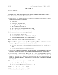


© Copyright 2026