
Air Grippers
Parallel Style Air Gripper – Series MHZ2/MHZJ2 767 Parallel Style Air Gripper Standard Type/With Dust Cover Series MHZ2/MHZJ2 Size MHZ2: ø6, ø10, ø16, ø20, ø25, ø32, ø40 Size MHZJ2: ø6, ø10, ø16, ø20, ø25 Standard type Features Features • Autoswitches can be added. • Single and double acting design. • MHZ2: General purpose compact grippers with integral linear guide that provides high rigidity and high accuracy. • MHZJ2: Air grippers with dust-protected and drip-proof construction. Interchangeable in mounting dimensions with the standard models. With dust cover How to Order Standard type MHZ2 16 D 2 fingers Finger position/option Standard 6 mm 25 25 mm 6 10 10 mm 32 32 mm 16 16 mm 40 40 mm 20 20 mm Action D Double acting S Single acting (Normally open) C Single acting (Normally closed) With Dust Cover MHZJ2 – F S Bore size D S C Double acting Single acting (Normally open) Single acting (Normally closed) Refer to next pages for MHZJ Specifications – Basic type E End boss type Side ported K End boss type Axial ported with ø4 one-touch fitting (single acting) M End boss type Axial M5 port (single acting) W End boss type Axial ported with ø4 one-touch fitting for coaxial tubing (Double acting) Dust cover type 2 fingers Action (MHQ2 compatible type) (MHQG2 compatible type) –: Basic type N: Basic type 1: Side tapped mounting N1: Side tapped mounting 2: Through-holes in opening/ N2: Through-holes in opening/ closing direction closing direction 3: Flat type fingers (flat type fingers do not have standard and narrow options) 16 D 6 6 mm 20 20 mm 10 10 mm 25 25 mm 16 16 mm Body option (only ø10 to ø25) Narrow type (only ø10 to ø25) Chloroprene rubber (CR) Fluororubber (FKM) Silicon rubber (Si) Body option (ø6 is only applicable with basic type) – Basic type E End boss type Side ported K End boss type Axial ported with ø4 one-touch fitting for coaxial tubing (single acting) M End boss type Axial ported with ø5 port (single acting) W End boss type Axial ported with ø4 one-touch fitting for coaxial tubing (Double acting) Product Recomendation Auto Switches Stocked items for fast delivery Part Number MHZ2-C MHZ2-CN MHZ2-D MHZ2-D1 MHZ2-D2 MHZ2-D3 MHZ2-DN MHZ2-DN2 MHZ2-DNW MHZ2-S Stroke () 6, 10, 16, 20, 25, 32, 40 10, 16, 20, 25 6, 10, 16, 20, 25, 32, 40 6, 16 6, 10, 16, 20, 32, 40 10, 16, 20, 25, 40 10, 16, 20, 25 10, 20 10, 20 6, 10, 16, 20, 25, 40 Part Number MHZ2-S2 MHZ2-S3 MHZ2-SM MHZ2-SN MHZJ2-C MHZJ2-D MHZJ2-DF MHZJ2-DS MHZJ2-S MHZJ2-SM Stroke () 6 10, 16 16, 20 10, 16, 20, 25 6, 10, 16, 20, 25 6, 10, 16, 20 20, 25 6, 10, 16, 20, 25 10, 20, 25 25 • D-M9PWL (PNP 2-colour indication) • D-M9NWL (NPN 2-colour indication) • D-M9PL (PNP) • D-M9NL (NPN) Note) For more options see the Auto Switch section, page XXX Related Products Series D-7K/D-RK - Speed Controllers - page 1032 Series AS - Speed Controllers - page 1238 Series SY - Valves - page 65, 101, 417 Series SV - Valves - page 20 Series VQC - Valves - page 193, 211 Series AC - Air Preparation - page 1076 Series IDK - Moisture Control Tube - page 1149 Series TU - Tubing - page 1223 Series KQ2 - Fittings - page 1184 For more product options and details see our specific catalogues or on-line information. Grippers Bore size 768 Series MHZ2/MHZJ2 – Parallel Style Air Gripper Specifications MHZ2 Finger position/Option Standard type [MHQG2 compatible type] Nil: Basic type Body option Narrow type [MHQ2 compatible type] N: Basic type Nil: Basic type E: End boss type Side ported (double acting/single acting) W: End boss type Axial port with ø4 One-touch fitting for coaxial tubing (double acting) Port 1: Side tapped mounting N1: Side tapped mounting 2: Through holes in opening/closing direction N2: Through holes in opening/closing direction Port Port Port M: End boss type Axial M5 port (single acting) K: End boss type Axial port with ø4 One-touch fitting (single acting) 3: Flat type fingers The flat type fingers do not have standard and narrow options. When MHQG2/MHQ2 compatible types are required, see the -X51 order made specifications. Port Seal kit no. MHZ2-10D MHZ2-16D MHZ2-20D MHZ2-25D MHZ2-32D MHZ2-40D MHZ10-PS MHZ16-PS MHZ20-PS MHZ25-PS MHZ32-PS MHZ40-PS Specifications Model Air ø6: 0.15 to 0.7 MPa Double acting ø10: 0.2 to 0.7 MPa Operating ø16 to ø40: 0.1 to 0.7 MPa pressure ø6: 0.3 to 0.7 MPa Single Normally open ø10: 0.35 to 0.7 MPa acting Normally closed ø16 to ø40: 0.25 to 0.7 MPa Ambient and fluid temperature –10 to 60ºC ø6 to ø25: ±0.01 mm Repeatability ø32, ø40: ±0.02 mm ø6 to ø25: 180 c.p.m. Max. operating frequency ø32, ø40: 60 c.p.m. Not required Lubrication Double acting/Single acting Action Solid state switch (3-wire, 2-wire) Auto switch (Option) Note) Fluid Action Normally open Double acting Single acting Symbol Double acting Single acting type, Normally open Single acting type, Normally closed Model Normally closed Grippers Replacement parts: Seal kits MHZ2-6D MHZ2-10D MHZ2-16D MHZ2-20D MHZ2-25D MHZ2-32D MHZ2-40D MHZ2-6S MHZ2-10S MHZ2-16S MHZ2-20S MHZ2-25S MHZ2-32S MHZ2-40S MHZ2-6C MHZ2-10C MHZ2-16C MHZ2-20C MHZ2-25C MHZ2-32C MHZ2-40C Gripping force (1) Opening/ Bore Closing stroke size Gripping force per finger Effective value [N] (Both sides) [mm] [mm] External Internal 6 10 16 20 25 32 40 6 10 16 20 25 32 40 6 10 16 20 25 32 40 3.3 11 34 42 65 158 254 1.9 7.1 27 33 45 131 217 — 6.1 17 45 66 104 193 318 — 3.7 13 38 57 83 161 267 4 4 6 10 14 22 30 4 4 6 10 14 22 30 4 4 6 10 14 22 30 Note 1) Values based on pressure of 0.5 MPa, gripping point L = 20 mm, at center of stroke. Note 2) Except auto switch. Parallel Style Air Gripper – Series MHZ2/MHZJ2 769 Replacement Parts Specifications MHZJ2 Nil: Basic type Replacement parts: Dust covers E: End boss type W: End boss type Side ported (double Axial port with ø4 Port acting/single acting) One-touch fitting for coaxial tubing (double acting) Port Material Part no. CR MHZJ2-J6 FKM MHZJ2-J6F Si MHZJ2-J6S Port Replacement parts: Seal kits Description Seal kit no. include MHZJ2-10 MHZJ2-16 MHZJ2-20 MHZJ2-25 Kits items 19, 20 and 21 from the MHZJ10-PS MHZJ16-PS MHZJ20-PS MHZJ25-PS table on the left Note 2) Port Port K: End boss type Axial port with ø4 One-touch fitting (single acting) M: End boss type Axial M5 port (single acting) Replacement parts: Dust covers Material CR FKM Si Part no. MHZJ2-10 MHZJ2-J10 MHZJ2-J10F MHZJ2-J10S MHZJ2-16 MHZJ2-J16 MHZJ2-J16F MHZJ2-J16S MHZJ2-20 MHZJ2-J20 MHZJ2-J20F MHZJ2-J20S MHZJ2-25 MHZJ2-J25 MHZJ2-J25F MHZJ2-J25S ∗ ø6 is only applicable with basic type. Fluid Double acting Operating pressure Single Normally open acting Normally closed Ambient and fluid temperature Repeatability Maximum operating frequency Lubrication Action Auto switch (option) Note) Grippers Specifications Air ø6: 0.15 to 0.7MPa ø10: 0.2 to 0.7MPa ø16 to ø25: 0.1 to 0.7MPa ø6: 0.3 to 0.7MPa ø10: 0.35 to 0.7MPa ø16 to ø25: 0.25 to 0.7MPa –10 to 60ºC 0.01mm 180c.p.m. Non-lube Double acting, Single acting Solid state switch (3 wire, 2 wire) Models Action Single acting Normally closed Normally open Double acting Model Bore size [mm] MHZJ2- 6D MHZJ2-10D MHZJ2-16D MHZJ2-20D MHZJ2-25D MHZJ2- 6S MHZJ2-10S MHZJ2-16S MHZJ2-20S MHZJ2-25S MHZJ2- 6C MHZJ2-10C MHZJ2-16C MHZJ2-20C MHZJ2-25C 6 10 16 20 25 6 10 16 20 25 6 10 16 20 25 Gripping force Note 1) Opening/ Note 2) Gripping force per finger Closing Weight Effective value [N] stroke (both sides) Internal External [g] gripping force gripping force [mm] 3.3 9.8 30 42 65 1.9 6.3 24 28 45 — 6.1 17 40 66 104 — 3.7 12 31 56 83 4 4 6 10 14 4 4 6 10 14 4 4 6 10 14 28 60 130 250 460 28 60 130 255 465 28 60 130 255 465 Note 1) Values based on pressure of 0.5MPa, gripping point L = 20mm, at center of stroke. Note 2) Values excluding weight of auto switch. For more product options and details see our specific catalogues or on-line information. 770 Series MHZ2/MHZJ2 – Parallel Style Air Gripper Finger Options MHZ2 Side Tapped Mounting [1/N1] S Through Holes in Opening/Closing Direction [2/N2] O 4-MM through Attachment mounting thread S O 4-H through Attachment mounting hole B C C A A B A 2.5 3 4 5 6 7 9 B 5 5.7 7 9 12 14 17 C 2 2 2.5 4 5 6 7 MM M2 M2.5 M3 M4 M5 M6 M8 Unit: mm Model MHZ2- 6 2 2 MHZ2-10 N2 2 MHZ2-16 N2 2 MHZ2-20 N2 2 MHZ2-25 N2 MHZ2-322 MHZ2-402 ∗ Specifications and dimensions other than the above are the same as the basic type (including narrow type). A 2.5 3 4 5 6 7 9 B 5 5.7 7 9 12 14 17 Unit: mm H 2.4 2.9 3.4 4.5 5.5 6.6 9 ∗ Specifications and dimensions other than the above are the same as the basic type (including narrow type). B A B K K G A J 4-MM thread depth L Attachment mounting thread D J O W S Flat Type Fingers [3] D Grippers Model MHZ2- 6m 1 1 MHZ2-10m N1 m 1 MHZ2-16m N1 m 1 MHZ2-20m N1 m 1 MHZ2-25m N1 m MHZ2-32m1m MHZ2-40m1m F C Model A MHZ2- 63 ∗1) MHZ2-103 ∗2), ∗3) MHZ2-163 ∗2), ∗3) MHZ2-203 ∗2), ∗3) MHZ2-253 ∗2), ∗3) MHZ2-323 MHZ2-403 2 2.45 3.05 3.95 4.9 7.3 8.7 B 3.5 6 8 10 12 20 24 C D F 7.2 5.2 8.3 10.5 13.1 18 22 7.5 10.9 14.1 17.9 21.8 34.6 41.4 – 2 2.5 3 4 5 6 G Open Closed 5 +1.2 - 0.8 5.4 +2.2 0 +2.2 7.4 0 11.6 +2.3 0 +2.5 16 0 25 +2.7 0 +2.9 33 0 1 +0.2 0 0 1.4 -0.2 0 1.4 -0.2 0 1.6 -0.2 0 2 -0.2 0 3 -0.2 0 3 -0.2 Unit: mm J K MM L – 4.45 5.8 7.45 8.9 14.8 17.7 – 2H9 +0.025 0 2.5H9 +0.025 0 3H9 +0.025 0 4H9 +0.030 0 5H9 +0.030 0 6H9 +0.030 0 M2 M2.5 M3 M4 M5 M6 M8 3 5 6 8 10 12 16 ∗1) To mount attachments, use M2 hexagon socket head cap screws with ø3.3 top diameter, or JISB1101 type M2 round head screws. ∗2) Specifications and dimensions other than the above are the same as the basic type (including narrow type). ∗3) The overall length is the same as the MHQ(G) flat finger type. ∗4) The values inside ( ) are for the single acting type. W Weight g 0 26 4 -0.05 0 55 5 -0.05 0 115 8 -0.05 0 10 -0.05 235 (240) 0 12 -0.05 420 (425) 0 740 (785) ∗4) 15 -0.05 0 1335 (1430) ∗4) 18 -0.05 Parallel Style Air Gripper – Series MHZ2/MHZJ2 771 Body Options MHZ2 End Boss Type Applicable Models Symbol Piping port position E W K M Side ported Type of Piping Port MHZ2-10 M3 Axial port MHZ2-16 MHZ2-20 MHZ2-25 M5 With ø4 One-touch fitting for coaxial tube With ø4 One-touch fitting M5 x 0.8 Applicable model Single acting Double acting Normally open Normally closed –– –– –– –– Side Ported [E] Auto switch mounting groove (4 locations) (except ø10) Model øD1 øD2 End boss assembly 5 E A A Unit: mm D1 B D2 E -0.016 -0.043 MHZ2-10E MHZ-A1010 15 7 12f8 11 52.8 MHZ2-16E MHZ-A1610 20 10 16f8 -0.016 -0.043 15 58.7 MHZ2-20E MHZ-A2010 22 12 20f8 -0.020 -0.053 19 70.5 MHZ2-25E MHZ-A2510 25 15 25f8 -0.020 -0.053 24 82.9 Other dimensions and specifications correspond to the standard type. B Grippers Auto switch mounting groove (both sides) Kit no. ∗ Refer to the dimension table. ∗ When auto switches are used, side mounting with through holes is not possible. Axial Port (One-Touch Fitting for Coaxial Tubing) [W] Auto switch mounting groove (4 locations) (except ø10) Applicable coaxial tubing øD2 End boss assembly øD1 Auto switch mounting groove (both sides) E Model A B D1 D2 E MHZ2-10DW 15 7 12f8 -0.043 -0.016 11 52.8 MHZ2-16DW 20 10 16f8 -0.016 -0.043 15 58.7 MHZ2-20DW 22 12 20f8 -0.020 -0.053 19 70.5 15 -0.020 -0.053 24 82.9 MHZ2-25DW 5 B Max. 5 A ∗ Refer to the dimension table. ∗ When auto switches are used, side mounting with through holes is not possible. Changing from Coaxial to Single Tubing Changing to single tubing is possible by using a branch "Y" or branch tee fitting. In this case particularly, single tube fittings and tubing for ø3.2 will be necessary. Unit: mm 25 25f8 Other dimensions and specifications correspond to the standard type. Applicable coaxial tubing Model Specification Outside diameter Max. operating pressure Min. bending radius Operating temperature Material TW04B-20 4mm 0.6MPa 10mm –20 to 60C Nylon 12 Branch tee, Different diameter tee, Branch "Y", Male run tee Refer to catalogue CAT.E004-A "Coaxial Air Tubing System" regarding coaxial tubing. For more product options and details see our specific catalogues or on-line information. 772 Series MHZ2/MHZJ2 – Parallel Style Air Gripper Body Options MHZ2 End Boss Type Axial Port (with One-touch Fitting) [K] Auto switch mounting groove (4 locations) (except ø10) Applicable tubing øD1 øD2 End boss assembly 5 E Auto switch mounting groove (both sides) A Max. 5 B Model A B Unit: mm D1 D2 E -0.016 -0.043 MHZ2-10mmK 15 7 12f8 11 52.8 MHZ2-16mmK 20 10 16f8 -0.016 -0.043 15 58.7 -0.020 -0.053 19 70.5 24 82.9 MHZ2-20mmK 22 12 20f8 MHZ2-25mmK 25 15 25f8 -0.020 -0.053 Other dimensions and specifications correspond to the standard type. m:Either S or C is available. Applicable tubing Soft nylon Polyurethane Description/ Nylon tubing tubing tubing Model Specification T0425 TS0425 TU0425 4 4 Outside diameter [mm] 4 0.5 0.8 Max. operating pressure [MPa] 1.0 10 12 Min. bending radius [mm] 13 Operating temperature [ºC] –20 to 60 –20 to 60 –20 to 60 Nylon 12 Nylon 12 Polyurethane Material ∗ Refer to the dimension table. ∗ When auto switches are used, side mounting with through holes is not possible. Polyurethane coiled tubing TCU0425B-1 4 0.5 — –20 to 60 Polyurethane Axial Port (M5 Port) [M] M5 Piping port Auto switch mounting groove (4 locations) (except ø10) Model End boss assembly øD1 øD2 Grippers Refer to catalog CAT. E501-B "Air Fittings and Tubing" regarding One-touch fittings and tubing. E Auto switch mounting groove (both sides) 5 A A B Unit: mm D1 D2 E MHZ2-10mmM 15 7 12f8 -0.016 -0.043 11 52.8 MHZ2-16mmM 20 10 16f8 -0.016 -0.043 15 58.7 19 70.5 24 82.9 MHZ2-20mmM 22 12 20f8 -0.020 -0.053 MHZ2-25mmM 25 15 25f8 -0.020 -0.053 Other dimensions and specifications correspond to the standard type. m:Either S or C is available. B ∗ Refer to the dimension table. ∗ When auto switches are used, side mounting with through holes is not possible. Weights Model Unit: g End boss type (symbol) E W K M MHZ2-10mm 65 64 66 65 MHZ2-16mm 148 147 148 147 MHZ2-20mm 277 277 277 277 MHZ2-25mm 495 495 496 494 Parallel Style Air Gripper – Series MHZ2/MHZJ2 773 Body Options End Boss Type MHZJ2 Applicable Models Type of piping port Symbol Piping port position E W K M Side ported MHZJ2-10 M3 Axial port MHZJ2-16 MHZJ2-20 MHZJ2-25 Double acting — — M5 With ø4 One-touch fitting for coaxial tube With ø4 One-touch fitting M5 x 0.8 Applicable model Single acting Normally open Normally closed — — Side Ported [E] Unit: mm Auto switch mounting groove (4 locations) (except ø10) øD1 øD2 End boss assembly Model A B D1 E D2 MHZJ2-10E 15 7 12f8 -0.016 -0.043 11 40 MHZJ2-16E 20 10 16f8 -0.016 -0.043 15 43.5 MHZJ2-20E 22 12 20f8 -0.020 -0.053 19 51.7 MHZJ2-25E 25 15 25f8 -0.020 -0.053 24 61.3 Other dimensions and specifications correspond to the standard type. 5 A Grippers E Auto switch mounting groove (both sides) (ø10 only) B ∗ Refer to the dimension table. ∗ When auto switches are used on ø10, side mounting with through holes is not possible. Axial Port (One-touch Fitting for Coaxial Tubing) [W] Unit: mm Applicable coaxial tubing Auto switch mounting groove (4 locations) (except ø10) øD1 øD2 End boss assembly Max. 5 Auto switch mounting groove (both sides) (ø10 only) 5 E B A ∗Refer to the dimension table. ∗When auto switches are used on ø10, side mounting with through holes is not possible. Changing from Coaxial to Single Tubing Changing to single tubing is possible by using a branch "Y" or branch tee fitting. In this case particularly, single tube fittings and tubing for ø3.2 will be necessary. Model A B D1 E D2 MHZJ2-10DW 15 7 12f8 -0.016 -0.043 11 40 MHZJ2-16DW 20 10 16f8 -0.016 -0.043 15 43.5 MHZJ2-20DW 22 12 20f8 -0.020 -0.053 19 51.7 MHZJ2-25DW 25 15 25f8 -0.020 -0.053 24 61.3 Other dimensions and specifications correspond to the standard type. Applicable coaxial tubing Model Specification Outside diameter Max. operating pressure Min. bending radius Operating temperature Material TW04B-20 4mm 0.6MPa 10mm –20 to 60C Nylon 12 Branch tee, Different diameter tee, Branch "Y", Male run tee Refer to catalogue CAT.E004-A "Coaxial Air Tubing System" regarding coaxial tubing. For more product options and details see our specific catalogues or on-line information. 774 Series MHZ2/MHZJ2 – Parallel Style Air Gripper Body Options End Boss Type MHZJ2 Axial Port (with One-touch Fitting) [K] Unit: mm Applicable tubing Auto switch mounting groove (4 locations) (except ø10) Model øD1 øD2 End boss assembly D1 B A E D2 -0.016 -0.043 MHZJ2-10K 15 7 12f8 11 40 MHZJ2-16K 20 10 16f8 -0.016 -0.043 15 43.5 MHZJ2-20K 22 12 20f8 -0.020 -0.053 19 51.7 MHZJ2-25K 25 15 25f8 -0.020 -0.053 24 61.3 Other dimensions and specifications correspond to the standard type. :Either S or C is available. Max. 5 Auto switch mounting groove (both sides) (ø10 only) Applicable tubing B 5 Description/ Model A E ∗ Refer to the dimension table. ∗ When auto switches are used on ø10, side mounting with through holes is not possible. Specification Nylon tubing Soft nylon tubing T0425 TS0425 Polyurethane Polyurethane tubing coiled tubing TU0425 TCU0425B-1 4 4 4 4 Max. operating pressure [MPa] 1.0 0.8 0.5 0.5 Min. bending radius [mm] 13 12 10 — –20 to 60 Operating temperature [ºC] –20 to 60 –20 to 60 –20 to 60 Material Nylon 12 Polyurethane Polyurethane Nylon 12 Refer to catalog CAT. E501-B "Air Fittings and Tubing" regarding One-touch fittings and tubing. Axial Port (M5 Port) [M] Unit: mm Auto switch mounting groove (4 locations) (except ø10) End boss assembly øD1 øD2 Grippers Outside diameter [mm] Model A B D1 MHZJ2-10M 15 7 MHZJ2-16M 20 MHZJ2-20M 22 MHZJ2-25M 25 D2 E 12f8 -0.043 -0.016 11 40 10 16f8 -0.016 -0.043 15 43.5 12 20f8 -0.020 -0.053 19 51.7 15 -0.020 -0.053 24 61.3 25f8 Other dimensions and specifications correspond to the standard type. :Either S or C is available. 5 E Auto switch mounting groove (both sides) (ø10 only) M5 Piping port B A ∗ Refer to the dimension table. ∗ When auto switches are used on ø10, side mounting with through holes is not possible. Weights Unit: g End boss type (symbol) Model E W K M MHZJ2-10 70 70 70 70 MHZJ2-16 165 165 165 165 MHZJ2-20 290 290 290 290 MHZJ2-25 525 525 525 525 Parallel Style Air Gripper – Series MHZ2/MHZJ2 775 MHZ2-6 Double acting/Single acting. Basic type M3 (Finger closing port) ∗ M3 (Finger opening port) ∗ 4-M2 Through (Thread for mounting attachment) 1.6 0 4 –0.05 Dimensions 2.5 5 5.5 2-M3 through (Mounting thread) Prepared hole dia. 2.6 through (Mounting hole) ø7H8 +0.022 depth 0 1.5 0 8 –0.4 11 When closed 10 ±0.05 When open 12 ±1 20 12 0.6 0 4 –0.1 17 25.5 38.8 53 Auto Switch Mounting Groove Dimensions Auto switch mounting groove (For D-F, D-M9(V)) ∗ For single action, the port on one side is a breathing hole. For more product options and details see our specific catalogues or on-line information. Grippers ø4 2.5 4.8 776 Series MHZ2/MHZJ2 – Parallel Style Air Gripper Dimensions MHZ2-10 Double acting/Single acting. Basic type M3 (Finger closing port) ∗ 4–M2.5 through (Thread for mounting attachment) 11 0 5 –0.05 M3 (Finger opening port) ∗ 9 3 5.7 19 ∗ For single action, the port on one side is a breathing hole. 4 –0.1 depth 3 16 29 23 23 When open 15.2 0 depth 2 16.4 ±0.05 2-M3 thread depth 6 (Mounting thread) 6 12 37.8 57 27 11.4 Auto Switch Mounting Groove Dimensions 0 When closed 11.2 –0.7 18 7.6 ±0.02 +0.043 ø11H9 0 12 4-M3 thread depth 5.5 (Mounting thread) Prepared hole dia. 2.6 through (Mounting hole) 0 5.2 ±0.02 +2.2 +0.025 ø2H9 0 6.2 Auto switch mounting groove 5 5.4 Grippers 2-M3 thread depth 6 (Mounting thread) Note) When using D-Y59, D-Y69 and D-Y7 type auto switches, through-hole mounting is not possible. MHZ2-16 Double acting/Single acting. Basic type M5 (Finger closing port) ∗ 4-M3 through (Thread for mounting attachment) M5 (Finger opening port) ∗ 13 0 8 –0.05 ø3H9 +0.025 0 4 7.5 7 19 depth 3 ∗ For single action, the port on one side is a breathing hole. 2-M4 thread depth 8 24 0 When closed 14.9 –0.7 23.6 ±0.05 depth 2 +2.2 When open 20.9 –0.2 +0.043 ø17H9 0 15 4-M4 thread depth 8 (Mounting thread) Prepared hole dia. 3.4 through (Mounting hole) Note) 38 22 11 ±0.02 30.6 0 5 –0.1 6.5 ±0.02 24.5 15 42.5 7.5 67.3 30 Auto Switch Mounting Groove Dimensions 16 (Mounting thread) Auto switch mounting groove 6.2 5 (For D-Y) ø4 2-M4 thread depth 4.5 (Mounting thread) 5.8 11.6 Dimensions Auto switch mounting groove 2.1 (For D-F, D-M9(V)) Note) When using D-Y59, D-Y69 and D-Y7 type auto switches, through-hole mounting is not possible. Parallel Style Air Gripper – Series MHZ2/MHZJ2 777 Dimensions MHZ2-20 Double acting/Single acting. Basic type M5 (Finger closing port) ∗ 4-M4 through (Thread for mounting attachment) 0 10 –0.05 15 M5 (Finger opening port) ∗ +0.030 ø4H9 0 5 10 9 23 depth 4 ∗ For single action, the port on one side is a breathing hole. 30 4-M5 thread depth 10 (Mounting thread) Prepared hole dia. 4.3 through (Mounting hole) 50 2-M5 thread depth 10 (Mounting thread) 20 0 When closed 16.3 –0.7 depth 3 27.6 ±0.05 +2.2 +0.052 ø21H9 0 18 When open 26.3 –0.2 32 16.8 ±0.02 42 0 8 -0.1 7.5 ±0.02 29 9.5 52.8 84.8 35 18.6 Auto Switch Mounting Groove Dimensions Auto switch mounting groove 6.2 5 (For D-Y) Grippers 9 ø4 2-M5 thread depth 8 14 (Mounting thread) Auto switch mounting groove (For D-F, D-M9(V)) 2.1 Note) When using D-Y59, D-Y69 and D-Y7 type auto switches, through-hole mounting is not possible. Dimensions MHZ2-25 Double acting/Single acting. Basic type M5 (Finger closing port) ∗ 4-M5 through (Thread for mounting attachment) M5 0 12 –0.05 20 (Finger opening port) ∗ 6 10.7 12 23.5 ∗ For single action, the port on one side is a breathing hole. 10 –0.1 depth 4 33.6 ±0.05 2-M6 thread depth 12 (Mounting thread) Auto Switch Mounting Groove Dimensions +2.5 36 30 25 11 63.6 102.7 36.5 Auto switch mounting groove (For D-Y) 22 6.2 5 depth 3.5 When open 33.3 –0.2 +0.052 ø26H9 0 22 4-M6 thread depth 12 (Mounting thread) Prepared hole dia. 5.1 through (Mounting hole) Note) 63 52 21.8 ±0.02 40 0 10 ±0.02 0 When closed 19.3 –0.8 +0.030 ø4H9 0 11.5 ø4 19 2-M6 thread depth 10 (Mounting thread) Auto switch mounting groove 3.5 (For D-F, D-M9(V)) Note) When using D-Y59, D-Y69 and D-Y7 type auto switches, through-hole mounting is not possible. For more product options and details see our specific catalogues or on-line information. 778 Series MHZ2/MHZJ2 – Parallel Style Air Gripper Dimensions MHZ2-32 Double acting/Single acting. Basic type M5 (Finger closing port) ∗ 4-M6 through M5 (Finger opening port) ∗ 24 (Thread for mounting attachment) 0 15 –0.05 The values inside ( ) are dimensions for the single acting type. 11 7 31 (37) 14 depth 5 ∗ For single action, the port on one side is a breathing hole. 12 –0.1 +0.030 ø5H9 0 0 12 ±0.02 4-M6 thread depth13 (Mounting thread) 46 97 60 +0.062 depth 4 +2.5 ø34H9 0 26 (Mounting thread) 40 ±0.1 When open 48 0 2-M6 thread depth 13 Auto Switch Mounting Groove Dimensions 0 When closed 26 –0.5 23 ±0.02 46 Prepared hole dia. 5.1 through (Mounting hole) 40 (49) 29 12 67 (76) 113 (122) 48 (57) 6.2 5 Auto switch mounting groove 2-M6 thread depth 10 24 Grippers 11.5 ø4 26 (For D-Y) (Mounting thread) Auto switch mounting groove 3.3 (For D-F, D-M9(V)) Note) When using D-Y59, D-Y69 and D-Y7 type auto switches, through-hole mounting is not possible. Dimensions MHZ2-40 Double acting/Single acting. Basic type 4-M8 through (Thread for mounting attachment) M5 (Finger closing port) ∗ 0 18 –0.05 28 The values inside ( ) are dimensions for the single acting type. M5 (Finger opening port) ∗ depth5 0 14 ±0.02 12 38 (45) ∗ For single action, the port on one side is a breathing hole. 14 –0.1 +0.030 ø5H9 0 17 9 4-M8 thread depth 16 (Mounting thread) 56 119 72 29 ±0.02 56 Prepared hole dia. 6.6 through (Mounting hole) Note) 48 ±0.1 Auto Switch Mounting Groove Dimensions 36 0 49 (62) 15 83 (96) 139 (152) 58 (71) Auto switch mounting groove 32 (For D-Y) 13 29.4 6.2 5 depth4 When closed 30–0.5 (Mounting thread) +2.7 32 When open 60 0 +0.062 ø42H9 0 2-M8 thread depth 17 2-M8 thread depth 13 ø4 (Mounting thread) 3.7 Auto switch mounting groove (For D-F, D-M9(V)) Note) When using D-Y59, D-Y69 and D-Y7 type auto switches, through-hole mounting is not possible. Parallel Style Air Gripper – Series MHZ2/MHZJ2 779 Dimensions MHZJ2-6 Double acting/Single acting. Basic type With Dust Cover M3 (Finger closing port)∗ 4-M2 through (Thread for mounting attachment) 1.6 0 4–0.05 M3 (Finger opening port)∗ 5.5 5 17 0 4–0.1 2.5 1.5 0 11 28.7 53 10 ±0.05 Auto Switch Mounting Groove Dimensions (14) Auto switch mounting groove 4.8 (For D-F, D-M9(V)) MHZJ2-10Double acting/Single acting. Basic type With Dust Cover M3 (Finger closing port)∗ 4-M2.5 through (Thread for mounting attachment) 11 0 5–0.05 M3 (Finger opening port)∗ 7 3 5.7 19 depth 3 16 23 11.4 16.4 4-M3 thread depth 5.5 (Mounting thread) Prepared hole dia. 2.6 through (Mounting hole) 0 ±0.02 18 5.2 4-0.1 +0.025 0 (34) ø2H9 Auto Switch Mounting Groove Dimensions 23 31 12 57 0.05 2-M3 thread depth 6 (Mounting thread) 2 When closed 11.2 +0.043 depth 0 0 –0.7 ø11H9 +2.2 0 12 When open 15.2 7.6 ±0.02 27 ø4 (21) Auto switch mounting groove (Both sides) 2.5 Dimensions ∗ For single action, the port on one side is a breathing hole. 2.5 ø4 20 25.5 2-M3 thread depth 6 (Mounting thread) ∗ For single action, the port on one side is a breathing hole. Note) When using auto switches, through-hole mounting is not possible. For more product options and details see our specific catalogues or on-line information. Grippers +0.022 depth 0 When closed 8 –0.4 ø7H8 When open 12 ±1 (28) 12 2-M3 through (Mounting thread) Prepared hole dia. 2.6 through (Mounting hole) 780 Series MHZ2/MHZJ2 – Parallel Style Air Gripper Dimensions MHZJ2-16 Double acting/Single acting. Basic type With Dust Cover M5 (Finger closing port)∗ 4-M3 through (Thread for mounting attachment) 0 8 -0.05 13 M5 (Finger opening port)∗ 4 7.5 7 19 4-M4 thread depth 8 (Mounting thread) Prepared hole dia. 3.4 through (Mounting hole) 24 11 ±0.02 22 (45) 6.5 ±0.02 30.6 3 0 +0.025 depth 0 5 –0.1 ø3H9 15 When closed 34.8 67.3 23.6 ±0.05 +2.2 When open 20.9 –0.2 Auto Switch Mounting Groove Dimensions 0 14.9 –0.7 24.5 depth 2 ø17H9 +0.043 0 15 2-M4 thread depth 8 (Mounting thread) 30 2.1 11.6 Grippers ø4 16 (29.6) Auto switch mounting groove (Both sides) 2-M4 thread depth 4.5 (Mounting hole) ∗ For single action, the port on one side is a breathing hole. Dimensions MHZJ2-20 Double acting/Single acting. Basic type With Dust Cover 4-M4 through (Thread for mounting attachment) M5 (Finger closing port)∗ 0 10-0.05 15 M5 (Finger opening port)∗ 5 8.5 9 23 4 30 42 0 (58) 32 16.8 ±0.02 27.6 ±0.05 4-M5 thread depth 10 (Mounting thread) Prepared hole dia. 4.3 through (Mounting hole) 8 -0.1 7.5 ±0.02 18.6 +0.030 ø4H9 0 depth 43.5 84.8 35 (34.6) Auto switch mounting groove (Both sides) 20 14 ø4 0 –0.7 Auto Switch Mounting Groove Dimensions 29 3 When closed 16.3 2-M5 thread depth 10 (Mounting hole) +0.052 depth 0 +2.2 –0.2 ø21H9 When open 26.3 18 2-M5 thread depth 8 (Mounting hole) 2.1 ∗ For single action, the port on one side is a breathing hole. Parallel Style Air Gripper – Series MHZ2/MHZJ2 781 Dimensions MHZJ2-25 Double acting/Single acting. Basic type With Dust Cover M5 (Finger closing port)∗ 4-M5 through (Thread for mounting attachment) 12 0 –0.05 20 M5 (Finger opening port)∗ 6 12 9 24 4 0 10 ±0.02 52 21.8 ±0.02 40 (73) 4-M6 thread depth 12 (Mounting thread) Prepared hole dia. 5.1 through (Mounting hole) 36 +0.030 depth 0 10–0.1 ø4H9 19 2-M6 thread depth 10 (Mounting hole) ∗ For single action, the port on one side is a breathing hole. 3.5 For more product options and details see our specific catalogues or on-line information. Grippers 33.6 ±0.05 36.5 22 ø4 Auto switch mounting groove (Both sides) 53 102.7 (42) Auto Switch Mounting Groove Dimensions 25 When closed 2-M6 thread depth 12 (Mounting hole) 30 +0.052 depth3.5 0 0 19.3 –0.8 ø26H9 +2.5 When open 33.3 –0.2 22 782 Series MHF2 – Low Profile Air Gripper Low Profile Air Gripper Series MHF2 Size: ø8, ø12, ø16, ø20 Symbol Features Features • Height is approximately the 1/3 size of an equivalent Series MHZ2. • Different strokes available. • Autoswitches can be added. How to Order MHF 2 12 D Number of fingers — Axial piping type R Side piping type Stroke — 1 2 2 2 fingers Bore size [mm] 8 12 Body option 16 20 Body option –: Axial direction piping type R: Side piping type Short stroke Medium stroke Long stroke Action Port Port D Double acting Product Recommendation Grippers Stocked items for fast delivery MHF2-8D2R MHF2-8D MHF2-8D1 MHF2-8D2 MHF2-8DR MHF2-12D MHF2-12D1 MHF2-12D2 MHF2-16D1 MHF2-12DR MHF2-12D1R MHF2-12D2R MHF2-16D Auto Switches MHF2-16D2 MHF2-16DR MHF2-16D1R MHF2-16D2R MHF2-20DR MHF2-20D MHF2-20D1R MHF2-20D1 MHF2-20D2R MHF2-20D2 Specifications Operating pressure Ambient and fluid temperature Repeatability Short stroke Maximum Medium stroke operating frequency Long stroke Lubrication Action Note 1) This is the value when no offset load is applied to the finger. When an offset load is applied to the finger, the maximum value is 0.15 mm due to the influence of backlash of the rack and pinion. Model Model Double acting MHF2-8D MHF2-8D1 MHF2-8D2 MHF2-12D MHF2-12D1 MHF2-12D2 MHF2-16D MHF2-16D1 MHF2-16D2 MHF2-20D MHF2-20D1 MHF2-20D2 Note) For more options see the Auto Switch section, page XXX Related Products Air ø8: 0.15 to 0.7 MPa ø12 to 20: 0.1 to 0.7 MPa 10 to 60C (with no condensation) 0.05 mm Note 1) 120 c.p.m. 120 c.p.m. 60 c.p.m. Not required Double acting Fluid Action • D-M9PWL (PNP 2-colour indication) • D-M9NWL (NPN 2-colour indication) Note 1) Opening Cylinder Gripping force /closing Effective gripping bore stroke force per (Both sides) [mm] finger [N] [mm] 8 19 12 48 16 90 20 141 8 16 32 12 24 48 16 32 64 20 40 80 Note 1) At the pressure of 0.5 MPa, when gripping point L is 20 mm. Note 2) Excluding the auto switch weight Note 2) Weight [g] 65 85 120 155 190 275 350 445 650 645 850 1,225 Volume [cm3] Finger open side 0.7 1.1 2.0 1.9 3.3 6.1 4.9 8.2 14.9 8.7 15.1 28.0 Finger close side 0.6 1.0 1.9 1.6 3.0 5.8 4.1 7.4 14.0 7.3 13.7 26.6 Series AS - Speed Controllers - page 1238 Series SY - Valves - page 65, 101, 417 Series SV - Valves - page 20 Series VQC - Valves - page 193, 211 Series AC - Air Preparation - page 1076 Series IDK - Moisture Control Tube - page 1149 Series TU - Tubing - page 1223 Series KQ2 - Fittings - page 1184 Low Profile Air Gripper – Series MHF2 783 Replacement Features Parts Replaceable parts list Replacement part/Grease pack Kit No. Description Seal kit Description Kit No. MHF2-8D MHF2-8D1 MHF2-8D2 Guide unit GR-S-010 (10g) MHF8-PS MHF8-PS MHF8-PS-2 Cylinder unit GR-L-005 (5 g) MHF-A0802-1 MHF-A0802-2 Finger assembly MHF-A0802 Replaceable parts list Kit No. Description Seal kit MHF2-12D MHF2-12D1 MHF2-12D2 MHF12-PS MHF12-PS MHF12-PS MHF-A1202-1 MHF-A1202-2 MHF2-16D Kit No. MHF2-16D1 MHF2-16D2 MHF16-PS MHF16-PS MHF16-PS MHF-A1602-1 MHF-A1602-2 Finger assembly MHF-A1202 Description Seal kit Finger assembly MHF-A1602 Kit No. Seal kit MHF2-20D MHF2-20D1 MHF2-20D2 MHF20-PS MHF20-PS MHF20-PS MHF-A2002-1 MHF-A2002-2 Finger assembly MHF-A2002 Grippers Description Body Features Option Side Piping Type MHF2-DR A C B D D (∗Finger closing port) (∗Finger opening port) ∗For dimensions not given above, please refer to the table of dimensions on pages 9 through 20. Body option dimension table Model A 5.5 37 7 54 MHF2-12D2R 90 MHF2-16DR 54 9 14.8 M5 x 0.8 76 19 M5 x 0.8 23 M5 x 0.8 66 MHF2-20DR MHF2-20D2R M3 x 0.5 124 MHF2-16D2R MHF2-20D1R 11 38 MHF2-12DR MHF2-16D1R D 61 MHF2-8D2R MHF2-12D1R C 25 MHF2-8DR MHF2-8D1R Unit: mm B 10 94 154 For more product options and details see our specific catalogues or on-line information. 784 Series MHF2 – Low Profile Air Gripper Dimensions Features MHF2-8D 2-M3 thread depth 4 11 Mounting thread 22 4-M3 thread depth 4 14 Mounting thread 4-M2.5 thread depth 3 Attachment mounting thread 26 12 ø4 M2.5 15 Accessory option: Hexagon socket head screw (special screws) 2-ø2H9 6 +0.025 0 depth 2 6 10 32 2-M3 thread depth 4 22 14 11 11 E M3 Finger opening port E 2-ø2.6 through (Mounting hole)∗ 0.8 12 12 0.8 0.8 0.8 E-E Close: 0 +0.1 0 2.5H9 +0.025 depth 2.5 0 Open: 81 ∗ Use the attached hexagon socket head screws for mounting holes. 16 +0.025 0 depth 2.5 Auto Switch Mounting Groove Dimensions 1.3 2-M3 thread depth 7 ø4 3 Mounting thread 3 3 Groove for auto switch mounting 28.3 0 17 -0.1 2-ø4.5 ø2.5H9 15.8 Mounting thread 3.4 19 Grippers 36 5.9 10 M3 Finger closing port Low Profile Air Gripper – Series MHF2 785 Dimensions Features MHF2-8D1 2-M3 thread depth 4 11 Mounting thread 34 4-M3 thread depth 4 4-M2.5 thread depth 3 Attachment mounting thread 26 Mounting thread 26 12 ø4 M2.5 15 Accessory option: Hexagon socket head screw (special screws) 7 11 +0.025 0 depth 2 2-M3 thread depth 4 Mounting thread 32 48 15.8 5.9 34 E 0.8 2-ø4.5 14 14 0.8 0.8 E-E 0 M3 Finger closing port M3 Finger opening port +0.1 0 depth 2.5 Open: 161 ∗ Use the attached hexagon socket head screws for mounting holes. +0.025 0 28 depth 2.5 2.5H9 +0.025 0 17 -0.1 0.8 Close: 0 ø2.5H9 14 11 11 E 2-ø2.6 through (Mounting hole)∗ Grippers 11 2-ø2H9 19 7 Auto Switch Mounting Groove Dimensions 1.3 2-M3 thread depth 7 ø4 3 Mounting thread 40.3 3.4 3 3 Groove for auto switch mounting For more product options and details see our specific catalogues or on-line information. 786 Series MHF2 – Low Profile Air Gripper Dimensions Features MHF2-8D2 2-M3 thread depth 4 11 Mounting thread 58 8-M2.5 thread depth 3 Attachment mounting thread 50 4-M3 thread depth 4 Mounting thread 26 12 ø4 M2.5 15 Accessory option: Hexagon socket head screw (special screws) 2-ø2H9 8 5 5 8 +0.025 0 depth 2 72 32 58 15.8 E 4-ø2.6 through (Mounting hole)∗ 18 0.8 0.8 4-ø4.5 Close: 0 E-E 0.8 +0.1 0 M3 Finger opening port Open: 321 ∗ Use the attached hexagon socket head screws for mounting holes. 17 17 17 +0.025 0 depth 2.5 2.5H9 +0.025 0 0 17 -0.1 18 depth 2.5 0.8 ø2.5H9 14 11 11 E Auto Switch Mounting Groove Dimensions 1.3 3 64.3 3.4 3 3 ø4 Groove for auto switch mounting 4-M3 thread depth 7 Mounting thread 19 5.9 Grippers 2-M3 thread depth 4 Mounting thread M3 Finger closing port Low Profile Air Gripper – Series MHF2 787 Dimensions Features MHF2-12D 2-M4 thread depth 5 15 Mounting thread 38 4-M3 thread depth 4 4-M4 thread depth 5 Mounting thread 28 Attachment mounting thread 33 15 ø5 M3 20 Accessory option: Hexagon socket head screw (special screws) 2-ø2.5H9 9 9 depth 2.5 14 40 52 38 Grippers 14 +0.025 0 20 19 E 2-ø3.4 through (Mounting hole)∗ 25 7.7 15 14.8 E 0 20 -0.1 1 18 18 1 1 1 2-ø5.5 E-E M5 Finger opening port M5 Finger closing port +0.1 Close: 0 0 2-M4 thread depth 5 Open: 121 +0.025 0 26 depth 3 3H9 +0.025 0 ø3H9 Mounting thread depth 3 ∗ Use the attached hexagon socket head screws for mounting holes. Auto Switch Mounting Groove Dimensions 1.7 ø4 2-M4 depth 10 4 42 4 3 3.3 Mounting thread Groove for auto switch mounting For more product options and details see our specific catalogues or on-line information. 788 Series MHF2 – Low Profile Air Gripper Dimensions Features MHF2-12D1 2-M4 thread depth 5 15 Mounting thread 54 4-M4 thread depth 5 Mounting thread 8-M3 thread depth 4 44 Attachment mounting thread 33 15 ø5 M3 20 Accessory option: Hexagon socket head screw (special screws) 12 4.5 4.5 2-ø2.5H9 12 +0.025 0 depth 2.5 2-M4 thread depth 5 Mounting thread 40 54 20 7.7 19 15 14.8 E E 2-ø3.4 through (Mounting hole)∗ 20 1 21 1 1 21 1 Close: 0 0 E-E 0 -0.1 M5 Finger opening port +0.1 2-ø5.5 Open: 241 depth 3 ∗ Use the attached hexagon socket head screws for mounting holes. 42 +0.025 0 depth 3 3H9 ø3H9 +0.025 0 Auto Switch Mounting Groove Dimensions 1.7 2-M4 thread depth 10 4 3 3.3 ø4 Groove for auto switch mounting 58 4 M5 Finger closing port Mounting thread 25 Grippers 68 Low Profile Air Gripper – Series MHF2 789 Dimensions Features MHF2-12D2 2-M4 thread depth 5 15 Mounting thread 90 8-M3 thread depth 4 Attachment mounting thread 4-M4 thread depth 5 Mounting thread 80 15 33 ø5 M3 20 Accessory option: Hexagon socket head screw (special screws) 4.5 4.5 2-ø2.5H9 18 2-M4 thread depth 5 Mounting thread +0.025 0 depth 2.5 Grippers 18 M5 Finger closing port 104 40 90 20 4-ø3.4 through (Mounting hole)∗ 19 25 7.7 15 14.8 E E 0 1 27 1 1 27 20 -0.1 1 4-ø5.5 Close: 0 E-E M5 +0.1 0 Finger opening port Open: 481 +0.025 depth 0 26 26 26 3 +0.025 0 ø3H9 depth 3 ∗ Use the attached hexagon socket head screws for mounting holes. 3H9 Auto Switch Mounting Groove Dimensions 1.7 ø4 3.3 3 4-M4 thread depth 10 4 94 4 Mounting thread Groove for auto switch mounting For more product options and details see our specific catalogues or on-line information. 790 Series MHF2 – Low Profile Air Gripper Dimensions Features MHF2-16D 20 2-M5 thread depth 5.5 Mounting thread 52 36 4-M5 thread depth 5.5 8-M4 thread depth 4 Mounting thread 43 20 Attachment mounting thread 2-ø3H9 5 5 3 15 Grippers 2-M5 thread depth 5.5 Mounting thread 72 26 24 20 20 E E 1.2 2-ø7.5 25 25 1.2 1.2 E-E Close: 0 0 27-0.1 1.2 M5 Finger opening port +0.1 0 +0.030 depth 0 3 Open: 161 38 ø4H9 +0.030 0 depth 3 4H9 Auto Switch Mounting Groove Dimensions ø4 2.2 Mounting thread 3 4.6 2-M5 thread depth 12 6 Groove for auto switch mounting 57.5 Finger closing port 10.6 52 2-ø4.3 through (Mounting hole) M5 50 5 33 15 +0.025 depth 0 Low Profile Air Gripper – Series MHF2 791 Dimensions Features MHF2-16D1 2-M5 thread depth 5.5 20 Mounting thread 74 58 4-M5 thread depth 5.5 8-M4 thread depth 4 Attachment mounting thread 43 20 Mounting thread 2-ø3H9 18 5.5 5.5 +0.025 0 depth 3 18 74 26 24 20 20 E M5 Finger closing port 33 50 10.6 Mounting thread 94 E 2-ø4.3 through (Mounting hole) 0 1.2 29 1.2 1.2 2-ø7.5 1.2 29 M5 +0.1 Close: 0 0 E-E 27 -0.1 Finger opening port +0.030 0 60 depth 3 4H9 +0.030 0 ø4H9 depth 3 Open: 321 Auto Switch Mounting Groove Dimensions 2.2 2-M5 thread depth 12 ø4 Mounting thread 79.5 5 3 4.6 6 Groove for auto switch mounting For more product options and details see our specific catalogues or on-line information. Grippers 2-M5 thread depth 5.5 792 Series MHF2 – Low Profile Air Gripper Dimensions Features MHF2-16D2 2-M5 thread depth 5.5 20 Mounting thread 122 4-M5 thread depth 5.5 8-M4 thread depth 4 106 Attachment mounting thread 43 20 Mounting thread 2-ø3H9 5.5 5.5 depth 3 26 Grippers M5 Finger closing port 50 2-M5 thread depth 5.5 Mounting thread 142 122 26 10.6 26 +0.025 0 4-ø4.3 through (Mounting hole) 24 E 0 1.2 37 1.2 1.2 4-ø7.5 Close: E-E 37 1.2 27 -0.1 M5 Finger opening port +0.1 0 0 36 +0.030 depth 0 36 36 3 4H9 ø4H9 +0.030 depth 0 3 Open: 641 Auto Switch Mounting Groove Dimensions 2.2 4-M5 thread depth 12 3 4.6 ø4 Groove for auto switch mounting Mounting thread 6 127.5 5 33 20 20 E Low Profile Air Gripper – Series MHF2 793 Dimensions Features MHF2-20D 2-M6 thread depth 6 25 Mounting thread 56 4-M6 thread depth 6 40 8-M4 thread depth 4 Mounting thread 24 52 Attachment mounting thread 2-ø3H9 3 16 7.5 Grippers 16 +0.025 depth 0 7.5 86 2-M6 thread depth 6 Mounting thread 62 33 56 M5 Finger closing port 2-ø5.2 through (Mounting hole) 41 30 25 25 13 E E 1.2 2-ø10 31 31 1.2 1.2 E-E Close: 0 32 1.2 0 -0.1 M5 Finger opening port +0.1 0 Open: 201 depth 4 Auto Switch Mounting Groove Dimensions +0.030 0 2.3 ø4 6 3 +0.030 0 5H9 ø5H9 depth 4 38 2-M6 thread depth 15 Mounting thread 6 71 6 Groove for auto switch mounting For more product options and details see our specific catalogues or on-line information. 794 Series MHF2 – Low Profile Air Gripper Dimensions Features MHF2-20D1 2-M6 thread depth 6 25 Mounting thread 84 4-M6 thread depth 6 8-M4 thread depth 4 68 Attachment mounting thread 52 24 Mounting thread 2-ø3H9 20 8 8 +0.025 0 depth 3 20 Grippers M5 Finger closing port 2-M6 thread depth 6 Mounting thread 114 62 84 33 2-ø5.2 through (Mounting hole) E 0 1.2 36 1.2 1.2 2-ø10 36 M5 Finger opening port +0.1 Close: 0 0 E-E 32 -0.1 1.2 Open: 401 +0.030 depth 0 +0.030 depth 0 ø5H9 4 66 4 5H9 Auto Switch Mounting Groove Dimensions 6 ø4 2.3 3 2-M6 thread depth 15 Mounting thread 6 Groove for auto switch mounting 99 6 41 30 25 25 13 E Low Profile Air Gripper – Series MHF2 795 Dimensions Features MHF2-20D2 25 2-M6 thread depth 6 Mounting thread 144 8-M4 thread depth 4 Attachment mounting thread 52 128 24 4-M6 thread depth 6 Mounting thread 2-ø3H9 8 8 30 +0.025 0 depth 3 Grippers 30 2-M6 thread depth 6 Mounting thread 62 33 144 30 25 25 E 4-ø5.2 through (Mounting hole) 1.2 0 32 -0.1 46 1.2 1.2 4-ø10 Close: E-E 46 1.2 +0.1 0 0 M5 M5 Finger opening port Finger closing port Open: 801 depth 4 42 4 5H9 +0.030 depth 0 42 +0.030 0 42 ø5H9 13 E 41 174 Auto Switch Mounting Groove Dimensions ø4 2.3 3 6 4-M6 thread depth 15 Mounting thread 6 159 6 Groove for auto switch mounting For more product options and details see our specific catalogues or on-line information. 796 Series MHL2 – Parallel Style Air Gripper: Wide Type Parallel Style Wide Opening Air Gripper Series MHL2 Size: 10, 16, 20, 25, 32, 40 Features Features • Easy to mount body and jaw accesories. • A wide opening with large open/close stroke. Optimally used for holding large-size workpieces that have dimensional variances. • The double pistons provide a large gripping force. • Autoswitches can be added. How to Order MHL 2 32 D1 Wide opening Number of fingers 2 2 fingers Opening/Closing stroke Symbol – Bore size 10 10 mm 16 16 mm 20 20 mm 25 25 mm 32 32 mm 40 40 mm ø10 ø16 30 60 80 20 40 60 1 2 ø20 40 80 100 [mm] ø25 50 100 120 ø32 ø40 70 120 160 100 160 200 Action D Double acting Thread port type M5 Rc G – Grippers TF Product Recommendation ø10 to ø25 ø32, ø40 Auto Switches Stocked items for fast delivery MHL2-10D MHL2-16D MHL2-10D1 MHL2-16D1 MHL2-10D2 MHL2-16D2 MHL2-20D MHL2-25D MHL2-40D MHL2-32D • D-M9PWL (PNP 2-colour indication) • D-M9NWL (NPN 2-colour indication) MHL2-40D1 MHL2-20D1 MHL2-25D1 MHL2-32D1 MHL2-40D2 MHL2-20D2 MHL2-25D2 MHL2-32D2 Note) For more options see the Auto Switch section, page XXX Specifications 10 Bore size [mm] 16 Fluid 20 Air 25 32 Related Products 40 Series D-7K/D-RK - Speed Controllers - page 997 Series AS - Speed Controllers - page 1238 Series SY - Valves - page 65, 101, 417 Series SV - Valves - page 20 Series VQC - Valves - page 193, 211 Series AC - Air Preparation - page 1076 Series IDK - Moisture Control Tube - page 1149 Series TU - Tubing - page 1223 Series KQ2 - Fittings - page 1184 Double acting Action Operating pressure [MPa] 0.1 to 0.6 0.15 to 0.6 –10 to 60ºC Ambient and fluid temperature ±0.1 Repeatability Lubrication Not required Effective gripping force [N] at 0.5 MPa 14 45 74 131 228 396 Note) Gripping point = Bore size 10, 16, 20, 25: 40 mm, Bore size 32, 40: 80 mm. Model/Stroke Model MHL2-10D MHL2-10D1 MHL2-10D2 MHL2-16D MHL2-16D1 MHL2-16D2 MHL2-20D MHL2-20D1 MHL2-20D2 Max. Opening/ Width at Bore operating Closing size frequency stroke [mm] closing [mm] [mm] [c.p.m.] L2 – L1 L1 10 16 20 60 40 60 40 60 40 20 40 60 30 60 80 40 80 100 56 78 96 68 110 130 82 142 162 Width at opening Weight [mm] [g] L2 76 118 156 98 170 210 122 222 262 280 345 425 585 795 935 1025 1495 1690 Model MHL2-25D MHL2-25D1 MHL2-25D2 MHL2-32D MHL2-32D1 MHL2-32D2 MHL2-40D MHL2-40D1 MHL2-40D2 Max. Opening/ Width at Bore operating closing size frequency Closing [mm] stroke [mm] [mm] [c.p.m.] L1 L2 – L1 60 25 40 30 32 20 30 40 Note) The open and close time spans represent the value when the exterior of the workpiece is being held. 20 50 100 120 70 120 160 100 160 200 100 182 200 150 198 242 188 246 286 Width at opening Weight [mm] [g] L2 150 282 320 220 318 402 288 406 486 1690 2560 2775 2905 3820 4655 5270 6830 7905 Parallel Style Air Gripper: Wide Type – Series MHL2 797 MHL2-10D Dimensions Features M5 (Finger closing port) Auto switch mounting groove (4 locations)∗ 4-M5 (Piston rod and rack screw) M5 (Finger closing port) Width across flats 8 (4 locations) K Closed E Open F 4-M4 x 0.7 through ø3H9 2-ø4.5 through +0.025 0 depth 3 (Body mounting hole) 3H9 +0.025 depth 3 0 ∗ Dimensions of auto switch mounting groove (Enlarged view) 4-M4 thread depth 8 (Mounting thread) ø18H9 +0.043 depth 3 0 2-M4 thread depth 5 (Mounting thread) Closed J K cross view (Fingers closed) [mm] Model MHL2-10D MHL2-10D1 MHL2-10D2 A 38 54 72 B 36 52 70 C 51 67 85 D 26 42 60 E 56 78 96 F 76 118 156 G 100 142 180 H 24 39 57 J 80 108 146 Note 1) J dimension is at fully closed. Note 2) D1 is different from D2 at finger closed because shaft is ejected from finger end. J dimension is different from the value which is subtracted stroke from G dimension. For more product options and details see our specific catalogues or on-line information. Grippers (Thread for mounting attachment) 798 Series MHL2 – Parallel Style Air Gripper: Wide Type Dimensions Features MHL2-16D M5 (Finger opening port) M5 (Finger closing port) Auto switch mounting groove (4 locations)∗ 4-M6 (Piston rod and rack screw) Width across flats 10 (4 locations) Closed E (Thread for mounting attachment) 4-M5 through Open F Grippers ø3H9 +0.025 depth 3 0 2-ø5.5 through (Body mounting hole) 3H9 +0.025 0 depth 3 4-M5 thread depth 10 (Mounting thread) ø23H9 ∗ Dimensions of auto switch mounting groove (Enlarged view) 2-M5 thread depth 7 (Mounting thread) Closed J K cross view (Fingers closed) [mm] Model MHL2-16D MHL2-16D1 MHL2-16D2 A 40 70 90 B 45 75 95 C 60 90 110 D 28 58 78 E 68 110 130 F 98 170 210 G 128 200 240 H 26 50 70 J 98 152 192 Note 1) J dimension is at fully closed. Note 2) D1 is different from D2 at finger closed because shaft is ejected from finger end. J dimension is different from the value which is subtracted stroke from G dimension. +0.052 0 depth 1.5 Parallel Style Air Gripper: Wide Type – Series MHL2 799 Dimensions Features MHL2-20D M5 (Finger opening port) M5 (Finger closing port) Auto switch mounting groove (4 locations)∗ 4-M6 (Piston rod and rack screw) Width across flats 10 (4 locations) Closed E Open F 4-M6 x 1 through ø4H9 +0.030 depth 4 0 2-ø6.6 through (Body mounting hole) 4-M6 thread depth 12 (Mounting thread) 4H9 ∗ Dimensions of auto switch mounting groove (Enlarged view) +0.030 0 depth 4 ø27H9 +0.052 depth 1.5 0 Closed J 2-M6 thread depth 7 (Mounting thread) K cross view (Fingers closed) [mm] Model MHL2-20D MHL2-20D1 MHL2-20D2 A 54 96 116 B 58 100 120 C 71 113 133 D 38 80 100 E 82 142 162 F 122 222 262 G 160 260 300 H 32 68 88 J 120 195 235 Note 1) J dimension is at fully closed. Note 2) D1 is different from D2 at finger closed because shaft is ejected from finger end. J dimension is different from the value which is subtracted stroke from G dimension. For more product options and details see our specific catalogues or on-line information. Grippers (Thread for mounting attachment) 800 Series MHL2 – Parallel Style Air Gripper: Wide Type MHL2-25D Dimensions Features Auto switch mounting groove (4 locations)∗ M5 (Finger opening port) M5 (Finger closing port) 4-M8 (Piston rod and rack screw) Width across flats 13 (4 locations) Closed E Open F 4-M8 through (Thread for mounting attachment) Grippers ø4H9 +0.030 depth 4.5 0 2-ø9 through (Body mounting hole) 4-M8 thread depth 16 4H9 ∗ Dimensions of auto switch mounting groove (Enlarged view) 2-M8 thread depth 7 (Mounting thread) [mm] Model MHL2-25D MHL2-25D1 MHL2-25D2 A 66 120 138 B 70 124 142 C 88 142 160 D 48 102 120 E 100 182 200 F 150 282 320 G 196 328 366 (Mounting thread) depth 4.5 ø32H9 Closed J K cross view (Fingers closed) +0.030 0 H 38 86 104 J 146 244 282 Note 1) J dimension is at fully closed. Note 2) D1 is different from D2 at finger closed because shaft is ejected from finger end. J dimension is different from the value which is subtracted stroke from G dimension. +0.052 0 depth 1.5 Parallel Style Air Gripper: Wide Type – Series MHL2 801 MHL2-32D Dimensions Features 1/8 1/8 (Finger closing port) Auto switch mounting groove (4 locations)∗ (Finger opening port) 4-M10 (Piston rod and rack screw) Width across flats 17 (4 locations) Closed E Open F ø6H9 +0.030 depth 8 0 4-M8 thread depth 16 (Mounting thread) 6H9 +0.030 depth 8 0 ∗ Dimensions of auto switch mounting groove (Enlarged view) ø35H9 +0.062 0 depth 2.5 2-M8 thread depth 11 (Mounting thread) Closed J K cross view (Fingers closed) [mm] Model MHL2-32D MHL2-32D1 MHL2-32D2 B 86 134 178 C 110 158 202 D 60 108 152 E 150 198 242 F 220 318 402 G 272 370 454 H 56 104 148 J 202 282 366 Note 1) J dimension is at fully closed. Note 2) D1 is different from D2 at finger closed because shaft is ejected from finger end. J dimension is different from the value which is subtracted stroke from G dimension. For more product options and details see our specific catalogues or on-line information. Grippers 4-M10 through (Thread for mounting attachment) 802 Series MHL2 – Parallel Style Air Gripper: Wide Type Dimensions Features MHL2-40D Auto switch mounting groove (4 locations)∗ 1/8 (Finger opening port) 1/8 (Finger closing port) 2-M10 (Rack screw) Width across flats 17 (2 locations) Width across flats 19 (2 locations) 2-M12 Closed E (Piston rod and rack screw) Open F 4-M12 through (Thread for mounting attachment) ø6H9 +0.030 0 depth 8 Grippers ∗ Dimensions of auto switch mounting groove ø6H9 +0.030 depth 8 0 (Enlarged view) ø40H9 Closed J K cross view (Fingers closed) 2-M10 thread depth 12 (Mounting thread) [mm] Model MHL2-40D MHL2-40D1 MHL2-40D2 B 116 174 214 C 148 206 246 4-M10 thread depth 20 (Mounting thread) D 80 138 178 E 188 246 286 F 288 406 486 G 348 466 546 H 72 130 170 J 252 336 450 Note 1) J dimension is at fully closed. Note 2) D1 is different from D2 at finger closed because shaft is ejected from finger end. J dimension is different from the value which is subtracted stroke from G dimension. +0.062 0 depth 2.5 Wedge Cam Operation Slide Guide Air Gripper – Series MHK2 803 Wedge Cam Operation Slide Guide Air Gripper Series MHK2 Size: ø12, ø16, ø20, ø25 Features Features • Standard and long stroke types. • Double acting or single acting versions. How to Order Symbol Features Standard type MHK 2 20 D Long stroke type MHKL 2 20 D Double acting Bore size 12 mm 16 mm 20 mm 25 mm Grippers 2 fingers 12 16 20 25 Normally closed Dust cover material – Chloroprene rubber (CR) F Fluororubber (FKM) S Silicon rubber (Si) Number of fingers 2 Single acting Normally open Finger material – Carbon steel 1 Stainless steel Action D Double acting S Single acting (Normally open) C Single acting (Normally closed) Also available To suit different environments, a selection of dust cover materials (fluoro and silicon rubber) and stainless steel 304 fingers is available, refer to Best Pneumatics catalogue. Product Recomendation Auto Switches Stocked items for fast delivery MHK2-12D MHK2-16D MHK2-20S MHK2-25S MHK2-12S MHK2-16S MHK2-20C MHK2-25C MHK2-12C MHK2-16C MHK2-20D1F MHK2-25DS MHK2-12D1S MHK2-20D MHK2-25D MHK2-25DF MHKL2-20C MHKL2-12D MHKL2-25D MHKL2-16D MHKL2-25S MHK2-25D1S MHKL2-20D • D-M9PL (PNP) • D-M9NL (NPN) Note) For more options see the Auto Switch section, page XXX Related Products Specifications Air Fluid Operating pressure Double acting Single acting Normally open Normally closed Ambient and fluid temperature Repeatability Lubrication Action 0.1 to 0.6 MPa 0.25 to 0.6 MPa –10 to 60ºC Series AS - Speed Controllers - page 1238 Series SY - Valves - page 65, 101, 417 Series SV - Valves - page 20 Series VQC - Valves - page 193, 211 Series AC - Air Preparation - page 1076 Series IDK - Moisture Control Tube - page 1149 Series TU - Tubing - page 1223 Series KQ2 - Fittings - page 1184 ±0.01 mm Not required Double acting/Single acting For more product options and details see our specific catalogues or on-line information. 804 Series MHK2 – Wedge Cam Operation Slide Guide Air Gripper Model Series MHK2/Standard Type Model Normally closed L2 Single acting L1 Normally open Double acting Action Bore size Max. operating frequency [mm] [c.p.] Note) Effective gripping force per finger [N] External grip: 15 Internal grip : 16 External grip: 31 Internal grip : 36 External grip: 46 Internal grip : 56 External grip: 80 Internal grip : 86 MHK2-12D 12 MHK2-16D 16 MHK2-20D 20 MHK2-25D 25 MHK2-12S 12 9 MHK2-16S 16 23 MHK2-20S 20 34 MHK2-25S 25 58 MHK2-12C 12 MHK2-16C Opening/Closing Width at Width at Weight opening stroke [mm] closing [mm] [mm] [g] L2–L1 L2 L1 4 9 6 14.6 20.6 113 10 16 26 235 14 19 33 440 4 9 13 6 14.6 20.6 114 10 16 26 237 14 19 33 443 12 4 9 13 16 25 6 14.6 20.6 115 MHK2-20C 20 44 10 16 26 237 MHK2-25C 25 73 14 19 33 443 120 13 75 76 76 Grippers Series MHKL2/Long Stroke Type L2 Note) Opening/Closing Width at Width at opening Weight stroke [mm] closing [mm] [mm] [g] L2–L1 L1 L2 Effective gripping force per finger [N] External grip: 14 Internal grip : 16 External grip: 27 Internal grip : 30 External grip: 45 Internal grip : 53 External grip: 79 Internal grip : 90 MHKL2-12D 12 MHKL2-16D 16 MHKL2-20D 20 MHKL2-25D 25 MHKL2-12S 12 9 MHKL2-16S 16 17 MHKL2-20S 20 MHKL2-25S MHKL2-12C Double acting Single acting L1 Bore size Max. operating frequency [mm] [c.p.m] Normally open Model Normally closed Action 20 104 14.6 28.6 164 18 16 34 312 22 19 41 562 11 9 20 105 14 14.6 28.6 165 32 18 16 34 314 25 53 22 19 41 565 12 11 11 9 20 105 MHKL2-16C 16 22 14 14.6 28.6 166 MHKL2-20C 20 40 18 16 34 314 MHKL2-25C 25 63 22 19 41 565 90 11 9 14 Note) At the pressure of 0.5 MPa, when gripping point L is 20 mm. Single acting nomally open: External holding force, Single acting nomally closed: Internal gripping force. Replacement Parts MHKL2 Replacement Parts Material MHK2-12 MHK2-16 MHK2-20 MHK12-PS MHK16-PS MHK20-PS MHK-A1201 MHK-A1601 MHK-A2001 P3318103 P3318203 P3318303 P3318104 P3318204 P3318304 P3318104-1 P3318204-1 P3318304-1 MH-A1006 MHK2-J12 MHK2-J16 MHK2-J20 MHK2-J12F MHK2-J16F MHK2-J20F MHK2-J12S MHK2-J16S MHK2-J20S ∗ Order 2 pieces per one finger unit. Replacement part/Grease pack part no.: MH-G01 (30 g) MHK2-25 MHK25-PS MHK-A2501 P3318403 P3318404 P3318404-1 MHK2-J25 MHK2-J25F MHK2-J25S Description Seal kit Piston assembly Cam Carbon steel Finger Stainless steel Needle assembly CR Dust FKM cover Si Material Material Description Seal kit Piston assembly Cam Carbon steel Finger Stainless steel Needle assembly CR Dust FKM cover Si Material MHK2 Replacement Parts MHKL2-12 MHK12-PS MHK-A1201 P3318111 P3318112 P3318112-1 MHKL2-16 MHKL2-20 MHK16-PS MHK20-PS MHK-A1601 MHK-A2001 P3318211 P3318311 P3318212 P3318312 P3318212-1 P3318312-1 MH-A1006 MHKL2-J12 MHKL2-J16 MHKL2-J20 MHKL2-J12F MHKL2-J16F MHKL2-J20F MHKL2-J12S MHKL2-J16S MHKL2-J20S ∗ Order 2 pieces per one finger unit. Replacement part/Grease pack part no.: MH-G01 (30 g) MHKL2-25 MHK25-PS MHK-A2501 P3318411 P3318412 P3318412-1 MHKL2-J25 MHKL2-J25F MHKL2-J25S Wedge Cam Operation Slide Guide Air Gripper – Series MHK2 805 Dimensions MHK2-12/Standard model 4 X M3 through (Thread for mounting attachment) M3 (Finger closing port) 6 -0.05 S 9.4 Adjustment needle for finger speed 0 4 7 7 17.5 M3 (Finger opening port) 3H9 0 5 -0.1 4 X M4 thread depth 8 (Mounting thread) 0 -0.2 Closed 9 Groove position for auto switch mounting 22 15 Groove position for auto switch mounting (2 positions) 31 11.6 3 +1.2 0 13 22 28 84 Bottom hole dia. 3.4 through (Mounting hole) Open 13 depth 3 10 ±0.02 +0.025 0 20 34 ø3H9 depth 3 2 X M3 thread depth 6 (Mounting thread) deph 1.5 32.6 ø13H9 +0.043 0 +0.025 0 63 2 X M3 thread depth 4 (Mounting thread) 2.3 15 Note) For single acting, one port is used as bleed port. MHKL2-12/Long stroke model 4 X M3 through (Thread for mounting attachment) M3 (Finger closing port) 6 -0.05 S 9.4 Adjustment needle for finger speed 0 4 M3 (Finger opening port) 4 X M4 thread depth 8 (Mounting thread) 0 22 Groove position for auto switch mounting Groove position for auto switch mounting 26 15 (2 positions) 36 20 ±0.05 ø4 57 11.6 3 Closed 9 0 -0.2 +1.2 Open 20 0 76 2.3 9 13 30 Bottom hole dia. 3.4 through (Mounting hole) 8 4 depth 3 10 ±0.02 +0.025 0 3 2 X M3 thread depth 6 (Mounting thread) 1.5 20 43 ø3H9 41.6 ø13H9 +0.025 depth 0 7 21 5 -0.1 3H9 +0.043 depth 0 7 2 X M3 thread depth 5 20 (Mounting thread) Note) For single acting, one port is used as bleed port. For more product options and details see our specific catalogues or on-line information. Grippers 9 ø4 20 ±0.05 806 Series MHK2 – Wedge Cam Operation Slide Guide Air Gripper Dimensions MHK2-16/Standard model 4 X M3 through (Thread for mounting attachment) M5 (Finger closing port) 8 -0.05 0 13 S Adjustment needle for finger speed 0 4 7 7 18 3H9 M5 (Finger opening port) depth 3 0 Groove position for auto switch mounting (2 positions) 24.5 15 Groove position for auto switch mounting 13.6 3 33 67.3 Grippers 14 ø4 0 -0.2 23.6 ±0.05 Closed 14.6 24 30.6 10 4 15 +1.2 0 depth 3 12 ±0.02 43 +0.025 0 22 45 (Mounting thread) ø3H9 4 X M4 thread depth 8 (Mounting thread) Bottom hole ø3.4 through (Mounting hole) 5 -0.1 2 X M4 thread depth 8 depth 1.5 Open 20.6 +0.043 0 ø17H9 +0.025 0 2 X M4 thread depth 4 (Mounting thread) 2.3 16 Note) For single acting, one port is used as bleed port. MHKL2-16/Long stroke model 4 X M3 through (Thread for mounting attachment) M5 (Finger closing port) 8 -0.05 O 13 S Adjustment needle for finger speed 0 4 7 7 M5 X 0.8 (Finger opening port) 3 0 5 -0.1 23.6 ±0.05 Groove position for auto switch mounting (2 position) 28 15 38.5 ø4 0 14.6 -0.2 +1.2 0 Groove position for auto switch mounting 63 83 2.3 14 15 Closed depth 3 24 34 10 4 12 ±0.02 +0.025 0 22 54 56 (Mounting thread) ø3H9 4 X M4 thread depth 8 (Mounting thread) Bottom port ø3.4 through (Mounting hole) 2 X M4 thread depth 8 depth 1.5 Open 28.6 ø17H9 22.5 13.6 3 3H9 +0.043 0 +0.025 depth 0 2 X M4 thread depth 5 (Mounting thread) 22 Note) For single acting, one port is used as bleed port. Wedge Cam Operation Slide Guide Air Gripper – Series MHK2 807 Dimensions 4 X M4 through (Thread for mounting attachment) MHK2-20/Standard model M5 (Finger closing port) 0 -0.05 O 15 S Adjustment needle for finger speed 5 9 7.5 10 4H9 depth 4 0 0 -0.2 Closed 16 18 +1.2 0 Groove position for auto switch mounting Groove position for auto switch mounting (2 positions) 29 21 40 84.8 2 X M5 thread depth 8 (Mounting thread) 20 Grippers 18.6 ø4 27.6 ±0.05 15 3 depth 4 Open 26 30 42 13.5 16 ±0.02 +0.030 0 32 58 60 ø4H9 4 X M5 thread depth 10 (Mounting thread) Bottom hole ø4.3 through (Mounting hole) 8 -0.1 2 X M5 thread depth 10 (Mounting thread) depth 1.5 21 M5 (Finger opening port) 5 ø21H9 +0.052 0 +0.030 0 2.5 Note) For single acting, one port is used as bleed port. MHKL2-20/Long stroke model 4-M4 (Thread for mounting attachment) M5 (Finger closing port) 0 5 +0.052 depth 0 depth1.5 2 X M5 thread depth 10 (Mounting thread) 1.5 7.5 26.5 M5 (Finger opening port) 4 X M5 thread depth 10 (Mounting thread) Bottom hole ø4.3 through (Mounting hole) Groove position for auto switch mounting (2 positions) 0 -0.2 32 44.5 ø4 20 15 3 +1.2 0 Groove position for auto switch mounting 73.5 100 2.5 18.6 27.6 ±0.05 Closed 16 18 Open 34 4 30 46 13.5 32 +0.030 depth 0 16 ±0.02 ø4H9 68 70 5 0 ø21H9 9 8 -0.1 4H9 +0.030 0 O 10 –0.05 15 S Adjustment needle for finger speed 2 X M5 thread depth 8 (Mounting thread) 24 Note) For single acting, one port is used as bleed port. For more product options and details see our specific catalogues or on-line information. 808 Series MHK2 – Wedge Cam Operation Slide Guide Air Gripper Dimensions MHK2-25/Standard model 4 X M5 (Thread for mounting attachment) M5 (Finger closing port) 0 12 -0.05 O 20 S Adjustment needle for finger speed M5 (Finger opening port) 5 Groove position for auto switch mounting (2 positions) 3 0 -0.2 Closed 19 Groove position for auto switch mounting 30 26 22 16 +1.2 0 Open 33 36 52 17.5 4 20 ±0.02 40 74 71.6 +0.030 depth 0 ø4H9 4 X M6 thread depth 12 (Mounting thread) Bottom hole ø5.1 through (Mounting hole) ø4 2 X M6 thread depth 12 (Mounting thread) depth 1.5 8 23 depth 4 0 +0.052 0 ø26H9 +0.030 0 12 10 -0.1 4H9 6 47.2 102.7 33.6 ±0.05 22 Grippers 2 X M6 thread depth 10 (Mounting thread) 2.3 22 Note) For single acting, one port is used as bleed port. MHKL2-25/Long stroke model M5 (Finger closing port) 4 X M5 through (Thread for mounting attachment) 0 -0.05 20 Adjustment needle for finger speed depth 1.5 2 X M6 thread depth 12 (Mounting thread) 12 8 M5 (Finger opening port) 30 4 X M6 through depth 12 (Mounting thread) 0 +0.052 0 depth 4 Bottom hole ø5.1 through (Mounting hole) Groove position for auto switch mounting 38 53.5 Groove position for auto switch mounting 88.5 121 (2 positions) 2 X M6 thread depth 10 (Mounting thread) ø4 3 25 16 0 -0.2 Closed 19 Note) For single acting, one port is used as bleed port. 22 33.6 ±0.05 +1.2 0 22 36 56 17.5 40 depth 4 20 ±0.02 +0.030 0 Open 41 ø4H9 81.6 84 5 ø26H9 +0.030 0 12 10 -0.1 4H9 6 30 2.3 Parallel Style Air Gripper / 3 Finger – Series MHS3 809 3 Finger Parallel Style Air Gripper Series MHS3 Size: 16, 20, 25, 32, 40, 50, 63, 80, 100, 125 Features Features With Dust Cover Type Series MHSJ3 (ø16 to ø80) Also available, consult Best Pneumatics catalogue. Standard Type • Autoswitches can be added, and wide range sizes available. • Vertically compact due to its wedge-shape cam construction. Optimally used inloading/unloading cylindrically shaped workpieces onto machine tools and in operations that require the application of an external force, such as in press fitting operations. Long Stroke Type Series MHSL3 (ø16 to ø125) Also available, consult Best Pneumatics catalogue. How to Order MHS 3 80 D Through-hole Type Series MHSH3 (ø16 to ø80) Also available, consult Best Pneumatics catalogue. Action D Double acting 3 3 fingers Thread port type Bore size 16 16 mm 20 20 mm 25 25 mm 32 32 mm – 40 40 mm 50 50 mm 63 63 mm 80 80 mm 100 100 mm 125 125 mm TN TF M5 Rc NPT G Grippers Number of fingers ø10 to ø25 ø32, ø40 Auto Switches • D-M9PWL (PNP 2-colour indication) • D-M9NWL (NPN 2-colour indication) • D-M9PL (PNP) • D-M9NL (NPN) Product Recommendation Stocked items for fast delivery Note) For more options see the Auto Switch section, page XXX MHS3-16D MHS3-25D MHS3-40D MHS3-63D MHS3-100D MHS3-20D MHS3-32D MHS3-50D MHS3-80D MHS3-125D Related Products Series D-7K / D-RK - Trimmer Auto Switch - page 1032 Series AS - Speed Controllers - page 1238 Series SY - Valves - page 65, 101, 417 Series SV - Valves - page 20 Series VQ - Valves - page 241 Series AC - Air Preparation - page 1076 Series IDK - Moisture Control Tube - page 1149 Series TU - Tubing - page 1223 Series KQ2 - Fittings - page 1184 Model/Specifications Model Cylinder bore size [mm] MHS3-16D MHS3-20D MHS3-25D MHS3-32D MHS3-40D MHS3-50D MHS3-63D MHS3-80D MHS3-100D MHS3-125D 16 20 25 32 40 50 63 80 100 125 Air Fluid 0.2 to 0.6 Operating pressure [MPa] 0.1 to 0.6 –10 to 60 Ambient and fluid temperature [ºC] ±0.01 Repeatability [mm] Max. operating frequency [c.p.m.] 60 120 30 Not required Lubrication Double acting Action External grip Effective gripping force [N] at 0.5 MPa (1) Internal grip 14 25 42 74 118 187 335 500 750 1,270 16 28 47 82 130 204 359 525 780 1,320 Opening/Closing stroke [mm] (dia.) 4 4 6 8 8 12 16 20 24 32 60 100 140 237 351 541 992 1,850 3,340 6,460 Weight [g] Note 1) Values for ø16 to ø25 are with gripping point L = 20 mm, for ø32 to ø63 with gripping point L = 30 mm, and for ø80 to ø125 with gripping point L = 50 mm. Note 2) Open and closed diameter values apply for external gripping of workpieces. For more product options and details see our specific catalogues or on-line information. 810 Series MHS3 – Parallel Style Air Gripper / 3 Finger Dimensions Features MHS3-16D to 25D øWA, depth 1.5 22.5 AA 6 x M3, thread depth TB Attachment mounting threads AB øB Open EO Closed EC øVA, depth VB 3 FZ J 2H9 +0.025 0 FY Q K O FX XB pth , de A X 3-UA, thread depth UB P.C.D.R (mounting threads) 2 (Open DO) (Closed DC) 20 20 NB I G NA 3-øSA, counter bore dia. SB, counter bore depth SC P.C.D.R (mounting hole) CB 7 P (finger opening port) Grippers P (finger closing port) Auto switch mounting groove positions (2 locations) MHS3-20D MHS3-25D ø4 5 3 6.5 3 54 54 54 ø4 5 6 5 MHS3-16D 5 ø4 3 5 33 33 33 [mm] Model MHS3-16D MHS3-20D MHS3-25D Model MHS3-16D MHS3-20D MHS3-25D AA 35 38 40 AB 32 35 37 B 30 36 42 CB 11 13 15 SA 3.4 3.4 4.5 SB 6.5 6.5 8 SC 8 9.5 10 TB 5 6 6 DC 15 18 21 UA M3 M3 M4 DO 17 20 24 EC 5 6 7 UB 4.5 6 6 EO 7 8 10 FX FY 12.5 11 14.5 13 17 14.5 VA 2H9 +0.025 0 2H9 +0.025 0 3H9 +0.025 0 VB 2 2 3 FZ 3 3 5 G 25 27 28 I 4 5 5 WA XA 17H9 +0.043 2H9 +0.025 0 0 21H9 +0.052 2H9 +0.025 0 0 26H9 +0.052 3H9 +0.025 0 0 J 10 12 14 K 4 5 6 XB 2 2 3 NA 8 10 12 NB 0 5h9 -0.030 0 6h9 -0.030 0 6h9 -0.030 O 2 2.5 3 P M3 M5 M5 Q 6 7 8 R 25 29 34 Parallel Style Air Gripper / 3 Finger – Series MHS3 811 Dimensions Features MHS3-32D to 80D 22.5 AA 20 AC øWA, depth WB AB 6-TA, thread depth TB Attachment mounting threads J L FY B th X dep , XA Q K FX O øB Open EO Closed EC 20 (Open DO) (Closed DC) øVA, depth VB NB M FZ I 3-UA, thread depth UB P.C.D.R (mounting threads) NA G CB 3-øSA, counter bore dia. SB, counter bore depth SC P.C.D.R (mounting hole) CA Grippers P (finger opening port) P (finger closing port) 40 40 10 10 Auto switch mounting groove positions (4 locations) Y 5 6. 4 [mm] Model MHS3-32D MHS3-40D MHS3-50D MHS3-63D MHS3-80D Model MHS3-32D MHS3-40D MHS3-50D MHS3-63D MHS3-80D AA 44 47 55 66 82 O 4.5 4.5 5 5.5 6 AB 41 44 52 62 77 P M5 M5 M5 M5 1/8 AC 3 3 3 4 5 B 52 62 70 86 106 CA 8 9 9 12 13.5 Q 11 12 14 17 20 R 44 53 62 76 95 CB 16 17 20 22 27 SA 4.5 5.5 5.5 6.6 6.6 DC 28 31 35 43 53.5 SB 8 9.5 9.5 11 11 DO 32 35 41 51 63.5 SC 9 9 12 14 19 EC 8 10 11 15 21.5 TA M4 x 0.7 M4 x 0.7 M5 x 0.8 M5 x 0.8 M6 x 1 EO 12 14 17 23 31.5 TB 8 8 10 10 12 FX 22 26.5 31 38 47.5 FY 19.5 23.5 28 34.5 43.5 UA M4 M5 M5 M6 M6 FZ 5 6 6 7 8 UB 6 7.5 10 9 12 G 30.5 32 37.5 44 56 I 6 7 9 11 12 VA 3H9 +0.025 0 4H9 +0.030 0 +0.030 4H9 0 5H9 +0.030 0 6H9 +0.030 0 J 20 21 24 28 32 VB 3 4 4 5 6 K 9 9 10 11 12 L 2H9 3H9 4H9 6H9 8H9 WA 34H9 +0.062 0 42H9 +0.062 0 +0.074 52H9 0 65H9 +0.074 0 82H9 +0.087 0 +0.025 0 +0.025 0 +0.030 0 +0.030 0 +0.036 0 WB 2 2 2 2.5 3 M 2 2 2 3 4 XA 3H9 +0.025 0 4H9 +0.030 0 +0.030 4H9 0 5H9 +0.030 0 6H9 +0.030 0 NA 14 16 18 24 28 XB 3 4 4 5 6 NB 0 8h9 -0.036 0 8h9 -0.036 0 10h9 -0.036 0 12h9 -0.043 0 14h9 -0.043 Y 6 8 7 7.5 9 For more product options and details see our specific catalogues or on-line information. 812 Series MHS3 – Parallel Style Air Gripper / 3 Finger Dimensions Features MHS3-100D, 125D 22.5 AC øWA, depth WB 6-TA, thread depth TB Attachment mounting threads AB øB Open EO Closed EC øVA, depth VB AA 20 J L FY Q K O FX XB pth , de A X (Open DO) (Closed DC) 20 NB M FZ I 3-UA, thread depth UB P.C.D.R (mounting threads) NA G 3-øSA, counter bore dia. SB, counter bore depth SC P.C.D.R (mounting hole) CB CA P (finger opening port) Grippers P (finger closing port) Auto switch mounting groove positions (4 locations) MHS3-100D MHS3-125D 10 40 40 40 40 10 10 10 5 5 4 6. 0 1 13 15 90 7 12 5 4 6. 90 J 38 52 K 15 21 [mm] Model MHS3-100D MHS3-125D Model MHS3-100D MHS3-125D AA 96 122 O 7.5 10.5 AB 90 114 P 1/4 3/8 AC 6 8 B CA CB 134 18 30.6 166 23.5 38 Q 23 31 R 118 148 SA 9 11 DC 66 82 SB 14 17.5 DO 78 98 SC 21 34 EC 28 30 TA M8 M10 EO 40 46 FX 59 74 TB 16 20 FY 54 68 UA M8 M10 FZ 10 12 G 63 84 I 15 18 UB VA 8H9 +0.036 16 0 20 10H9 +0.036 0 VB 6 8 L 8H9 10H9 +0.036 0 +0.036 0 M 4 6 NA 34 40 WA WB XA 102H9 +0.087 8H9 +0.036 4 0 0 130H9 +0.100 6 10H9 +0.036 0 0 NB 0 18h9 -0.043 0 22h9 -0.052 XB 6 8 Parallel Style Air Gripper / 3 Finger – Series MHS3 813 Detailed Dimensions of Mounting Portion of End Plate 3-A screw depth B P.C.D.C øD de h pt E (B) øD (E) F F F-F [mm] Model MHS3-16D MHS3-20D MHS3-25D MHS3-32D MHS3-40D MHS3-50D MHS3-63D MHS3-80D MHS3-100D MHS3-125D A B 5.5 M2 5.4 5.2 M3 8 M4 9.5 C 12.5 15 17 21 22 26 33 40 54 62 øD 18H8 +0.027 0 21H8 +0.033 0 +0.033 23H8 0 27H8 +0.033 0 31H8 +0.039 0 35H8 +0.039 0 42H8 +0.039 0 +0.046 52H8 0 70H8 +0.046 0 82H8 +0.054 0 E 0.5 0.6 0.8 1 1.5 For more product options and details see our specific catalogues or on-line information. Grippers Dimensions Features 814 Series MHC2/MHCA2 – Angular Style Air Gripper Angular Style Air Gripper Standard Type/Short Body Type Series MHC2/MHCA2 ø6, ø10, ø16, ø20, ø25 MHC2 Features Features Symbol Features MHCA2 • MHC2: Angular style air gripper Series MHC. Auto switch is attachable. • MHCA2: Short body. Auto switch not attachable. • Single or double acting versions. • Mounting holes on several faces. Single acting How to Order MHC 2 Standard type Short body type Also available 6 D MHCA 2 6 D Short body (Auto switch not attachable) (Only ø6) Action D S The MHCA2-6 type offers 4 additional body options in addition to those shown in this catalogue Double acting Single acting Port Side piping Grippers Bore size [mm] 6 6 mm 10 10 mm 16 16 mm 20 20 mm 25 25 mm Number of fingers 2 2 fingers Port With ø4 one-touch fitting With ø4 hose nipple Port With M3 port Please contact SMC for further information. Product Recommendation Stocked items for fast delivery Auto Switches MHC2-6D MHC2-10S MHC2-16S MHC2-20S MHC2-25S MHC2-10D MHC2-16D MHC2-20D MHC2-25D MHCA2-6D • D-M9PL (PNP) • D-M9NL (NPN) Note) For more options see the Auto Switch section, page XXX Specifications Features Fluid Operating pressure Port Double acting Single acting Ambient and fluid temperature Repeatability Max. operating frequency Lubrication Action Air ø6: 0.15 to 0.6 MPa ø6: 0.3 to 0.6 MPa –10 to 60°C Related Products 0.01 mm (ø6:0.02 mm) 180 c.p.m Not required Double acting, Single acting Series D-7K/D-RK - Trimmer Auto Switch - page 1032 Series AS - Speed Controllers - page 1238 Series SY - Valves - page 65, 101, 417 Series AC - Air Preparation - page 1076 Series IDK - Moisture Control Tube - page 1149 Series TU - Tubing - page 1223 Series KQ2 - Fittings - page 1184 Model Action Model Double acting MHC2-6D MHCA2-6D Single acting MHC2-6S (Normally open) MHCA2-6S MHC2-10D Double acting MHC2-16D MHC2-20D MHC2-25D MHC2-10S MHC2-16S Single acting MHC2-20S MHC2-25S Cylinder Gripping bore moment Note 1) [mm] (Effective value) [N.m] 6 0.038 6 6 0.024 6 0.10 10 0.39 16 0.70 20 1.36 25 0.070 10 0.31 16 0.54 20 1.08 25 Note 1) At pressure 0.5 MPa. Note 2) Weight except auto switch. Opening/ Closing angle Weight (Both sides) [g] Note 2) 30° to 10° 30° to 10° 30° to 10° 30° to 10° 22 19 22 19 39 91 180 311 39 92 183 316 Replacement Parts Description Seal kit Finger assembly Piston assembly set Needle assembly MHC2-10 MHC2-16 MHC2-20 MHC2-25 MHC10-PS MHC16-PS MHC20-PS MHC25-PS MHC-A1003 MHC-A1603 MHC-A2003 MHC-A2503 MHC-A1002 MHC-A1602 MHC-A2002 MHC-A2502 MH-A1006 MH-A1606 MH-A1606 MH-A1606 ∗ Order 1 piece finger assembly per one unit. Replacement part/Grease pack part no.: GR-S-10 (10 g) Angular Style Air Gripper – Series MHC2/MHCA2 815 Dimensions Features Double Acting ø6 MHC2-6 7 M3 Finger closing port 1.6 0.005 4 0.025 M3 ∗Finger opening port 18 ∗ In the case of MHC2-6S, finger opening port is a breathing hole. hme nt m ount ing li mitin 16 g ran ge 2.5 14 2 When closed 10 When open 30 4 Auto switch mounting groove dimensions 6 36 10 0.05 Grippers 20 2.5 ø4 5 2 4.8 2 x M3 through Prepared hole dia. 2.6 through 11 12 Attac (48) 4 x M2 through (Attachment mounting threads) M3 ∗(Finger opening port) 1.3 4 MHCA2-6 (Short body type) 0.8 -0.005 -0.025 ø7H8 +0.022 depth 1.5 0 M3 Finger closing port 5.5 14.3 ∗In the case of MHCA2-6S, finger opening port is a breathing hole. hmen nting limitin ge 11 2 5 14 4 6 29 +0.022 ø7H8 0 depth 1.5 (41) 2 x M2 thread depth 4 (Mounting thread) 4 x M2 through (Attachment mounting thread) 5 10 0.05 2 x M3 through Prepared hole dia. 2.6 through 2 When closed 10 When open 30 16 g ran 2.5 2 x M2 depth 6 (Mounting thread) 20 13.6 4 t mou 12 Attac 10 For more product options and details see our specific catalogues or on-line information. 816 Series MHC2/MHCA2 – Angular Style Air Gripper Dimensions Features Double Acting ø10, ø16 MHC2-10 Grippers Note) When single acting type is used, one side port is bleed port and adjusting needle for finger speed is not attached. ∗ When auto switch is used, through hole mounting type is not available. MHC2-16 Note) When single acting type is used, one side port is bleed port and adjusting needle for finger speed is not attached. ∗ When auto switch is used, through hole mounting type is not available. Angular Style Air Gripper – Series MHC2/MHCA2 817 Dimensions Features Double Acting ø20, ø25 MHC2-20 Grippers Note) When single acting type is used, one side port is bleed port and adjusting needle for finger speed is not attached. ∗ When auto switch is used, through hole mounting type is not available. MHC2-25 Note) When single acting type is used, one side port is bleed port and adjusting needle for finger speed is not attached. ∗ When auto switch is used, through hole mounting type is not available. For more product options and details see our specific catalogues or on-line information. 818 Series MHY2 – 180° Angular Style Air Gripper 180° Angular Style Air Gripper Cam Style Series MHY2 Size: ø10, ø16, ø20, ø25 Features Features • Lightweight and compact size through the use of a cam mechanism. Clamping workpiece Assembly Symbol Features • Butterfly gripper. • No Z axis required in pick and place. • Eases jig and fixture design. Grippers How to Order Product Recommendation MHY 2 16 D Number of fingers Bore size –: Standard tap mounting 10 10 mm 16 16 mm 2 2 fingers 20 20 mm 25 25 mm Stocked items for fast delivery Finger option 2: Opening/closing direction through hole MHY2-10D MHY2-20D MHY2-10D2 MHY2-16D MHY2-25D MHY2-16D2 Action Auto Switches D Double acting • D-M9PWL (PNP 2-colour indication) • D-M9NWL (NPN 2-colour indication) Note) For more options see the Auto Switch section, page XXX Model Bore size Effective gripping force [N·m] [mm] Model Note1) Opening/Closing angle Weight (Both sides) Opening side Closing side [g] MHY2-10D 10 0.16 70 MHY2-16D 16 0.54 150 MHY2-20D 20 1.10 MHY2-25D 25 2.28 180° –3° Related Products Note 2) 320 560 Series AS - Speed Controllers - page 1238 Series SY - Valves - page 65, 101, 417 Series SV - Valves - page 20 Series VQC - Valves - page 193, 211 Series AC - Air Preparation - page 1076 Series IDK - Moisture Control Tube - page 1149 Series TU - Tubing - page 1223 Series KQ2 - Fittings - page 1184 Note 1) At the pressure of 0.5 MPa Note 2) Except auto switch Model/Specifications Replacement Parts Description Seal kit Finger assembly Joint assembly MHY2-D MHY2-10D MHY2-16D MHY2-20D MHY2-25D Fluid MHY10-PS MHY16-PS MHY20-PS MHY25-PS Operating pressure MHY-A2501 Ambient and fluid temperature MHY-A1001 MHY-A1601 MHY-A2001 MHY2-D2 MHY-A1001-2 MHY-A1601-2 MHY-A2001-2 MHY-A2501-2 MHY-A1002 ∗ Order 1 piece of finger assembly per one unit. Replacement part/grease pack part no. : MH-G04 (30g) MHY-A1602 MHY-A2002 MHY-A2502 Air 0.1 to 0.6 MPa –10 to 60ºC Repeatability 0.2 mm Max. operating frequency 60 c.p.m. Lubrication Action Not required Double acting 180° Angular Style Air Gripper – Series MHY2 819 Dimensions Features MHY2-10D2 Opening/closing direction through hole type M5 (Finger opening port) 3 MHY2-10D S O ∗ Do not extend the attachment from limited area for mounting to avoid interference with the attachment or main body. 23 M5 (Finger closing port) 4 X M3 through 7 4- ø3.4 Through (Thread for mounting attachment) (Hole for mounting attachment) –0.005 –0.025 6 –0.005 35 Depth 1.5 47.5 9 6 12 12 6 (Limited area for mounting attachment∗) + 0.043 0 23.5 18 ø11H9 Positioning pin hole 3 3 24 22 30 (Mounting thread) (Limited area for mounting attachment∗) 2 - ø 3.4 through (Mounting hole) 2 X M3, depth 6 24 6 –0.025 4 X M3 Depth 6 (Mounting thread) 4 58 15 Auto switch mounting groove position Pin hole positioning Grippers 3H9 +0.025 0 ø4 4 3 9 9 13 30 2 X M3 Depth 4 (Mounting thread) Depth 3 2 MHY2-16D2 Opening/closing direction through hole type Dimensions Features MHY2-16D ∗ Do not extend the attachment from limited area for mounting to avoid interference with the attachment or main body. S 8 O M5 (Finger opening port) 4 X M3 through 25 M5 (Finger closing port) 20 41 Positioning pin hole 14 7 7 (Limited area for mounting attachment∗) 28 28.5 30 38 (Mounting hole) (Limited area for mounting attachment∗) 2-ø4.5 through 14 (Mounting thread) (Mounting thread) 30 –0.005 8 –0.025 4 4 X M4 Depth 8 2 X M4 Depth 8 +0.043 (Hole for mounting attachment) _ _0.005 0.025 4 8 5 ø17H9 0 Depth 1.5 4-ø 3.4 Through (Thread for mounting attachment) 7 55.5 12 69 20 Auto switch mounting groove position Pin hole positioning 3H9 +0.025 0 Depth 3 2 X M4 Depth 5 (Mounting thread) ø4 3 12 15 4 18 33 2.5 For more product options and details see our specific catalogues or on-line information. 820 Series MHY2 – 180° Angular Style Air Gripper Dimensions Features M5 (Finger operating port) MHY2-20D2 MHY2-20D O Opening/closing direction through hole type 12 S ∗ Do not extend the attachment from limited area for mounting to avoid interference with the attachment or main body. M5 (Finger closing port) 32 8 4-ø4.5 Through (Hole for mounting attachment) 2 X M4 through 4 X M5, depth 10 (Thread for mounting attachment) 36 25 ø21H9 0 Depth 1.5 Postioning pin hole (Limted area for mounting attachment∗) +0.052 37 36 48 38 (Mounting thread) 50 16 69 26 9 18 2-ø5.5 through (Mounting hole) 2 X M5 Depth 10 10 –0.005 –0.025 (Limted area for mounting attachment∗) 18 5 10 –0.005 –0.025 5 (Mounting thread) 9 8 86 Auto switch mounting groove position 2 X M5 Depth 8 14 3 19 5 Grippers 20 (Mounting thread) Pin hole positioning ø4 42 4H9 +0.030 Depth 4 0 3 Dimensions Features MHY2-25D M5 (Finger operating port) M5 42 Opening/closing direction through hole type 14 S O MHY2-25D2 ∗ Do not extend the attachment from limited area for mounting to avoid interference with the attachment or main body. 8 (Finger closing port) 4 X M5 through 4 X M6 Depth 12 12 42 30 60 18 6 86 30 107 Auto switch mounting groove position 16 24 (Mounting thread) 4H9 +0.030 0 Depth 4 50 ø4 3 23 5 Pin hole positioning 2 X M6 Depth 10 3 12 22.5 22.5 12 (Limted area for mounting attachment∗) +0.052 ø26H9 0 Depth 1.5 45 45 58 46 (Mounting thread) (Limted area for mounting attachment∗) 2-ø6.6 through (Mounting hole) 2 X M6 Depth 12 –0.005 –0.025 6 (Mounting thread) Postioning pin hole 4-ø5.5 Through (Thread for mounting attachment) 10 (Hole for mounting attachment) 12 –0.005 –0.025 Rotary Gripper – Series MRHQ 821 Rotary Gripper Series MRHQ Size: ø10, ø16, ø20, ø25 Features Features • The gripper function and the rotating function have been integrated in a compact package. • Eliminates the peripheral piping and wiring of the previous product (rotary table + adapter + air gripper). • Length reduced by approx. 20% compared with the previous product. • 2 standard rotation angles of 90º and 180º and angle adjustment bolts are standard. • Equipped with standard magnet for auto switch retrofitting. How to Order MRH Q 10 D 90 S N Single vane Rotary gripper Rotation angle 90º 180º Grippers 90 180 Gripper Q Parallel type: 2 fingers Action Gripper bore 10 16 20 25 D S C 10 mm 16 mm 20 mm 25 mm Double acting Single acting (normally open) Single acting (normally closed) Product Recommendation Auto Switches Stocked items for fast delivery MRHQ10D-90S-N MRHQ10S-180S-N MRHQ16C-90S-N MRHQ20D-90S-N MRHQ10C-90S-N MRHQ10C-180S-N MRHQ16D-180S-N MRHQ20D-180S-N MRHQ16S-180S-N MRHQ20C-180S-N MRHQ10D-180S-N MRHQ16D-90S-N MRHQ25D-90S-N MRHQ25D-180S-N • D-M9PVL (PNP) - for gripper opening/closing • D-M9NVL (NPN) - for gripper opening/closing • D-M9PL-746 (PNP) - for detection rotation • D-M9NL-746 (NPN) - for detection rotation Note) For more options see the Auto Switch section, page XXX Model/Specifications Features Related Products Model MRHQ10 MRHQ16 MRHQ20 Air Fluid Rotary unit 0.25 to 0.7 MPa Operating Double acting 0.25 to 0.7 MPa pressure Gripper unit Single acting 0.35 to 0.7 MPa 0.25 to 1.0 MPa 0.1 to 0.7 MPa 0.25 to 0.7 MPa Rotation angle 90º ±10º, 180º ±10º Gripper action Double acting, single Acting Finger opening/closing repeatability ±0.01mm Gripper maximum operating frequency 180 c.p.m Ambient and fluid temperature 5 to 60ºC Adjustable rotation time MRHQ25 Note) Allowable kinetic energy Series AS - Speed Controllers - page 1238 Series SY - Valves - page 65, 101, 417 Series SV - Valves - page 20 Series VQC - Valves - page 193, 211 Series AC - Air Preparation - page 1076 Series IDK - Moisture Control Tube - page 1149 Series TU - Tubing - page 1223 Series KQ2 - Fittings - page 1184 0.07 to 0.3 s/90º (at 0.5 MPa) 0.0046 J 0.014 J 0.034 J 0.074 J Note) Operate within the speed adjustment range, as speed control exceeding the limit value of the low speed may cause sticking or failure to operate. For more product options and details see our specific catalogues or on-line information. 822 Series MRHQ – Rotary Gripper Model Features Action Model MRHQ10D MRHQ16D Double acting MRHQ20D MRHQ25D MRHQ10S MRHQ10C Single acting MRHQ16S MRHQ16C MRHQ20S MRHQ20C MRHQ25S MRHQ25C Cylinder bore Opening/Closing stroke [mm] [mm] 4 10 6 16 10 20 14 25 4 10 6 16 10 20 14 25 Note) Rotating angle [º] Weight [g] 90 306 180 305 90 593 180 591 90 1055 180 1052 90 1561 180 1555 90 307 180 306 90 594 180 592 90 1060 180 1057 90 1566 180 1560 Grippers Note) Values do not include auto switch weight. Unit Features List Gripper unit Rotary unit Model Unit part no. Model Unit part no. MRHQ10D P407090-3D MRHQ10- 90S P406090-2A MRHQ10S P407090-3S MRHQ10-180S P406090-2B MRHQ10C P407090-3C MRHQ16D P407060-3D MRHQ16- 90S P406060-2A MRHQ16S P407060-3S MRHQ16-180S P406060-2B MRHQ16C P407060-3C MRHQ20- 90S P407080-2A P407080-3D MRHQ20-180S P407080-2B P408080-2A P408080-2B MRHQ20D MRHQ20S P407080-3S MRHQ25- 90S MRHQ20C P407080-3C MRHQ25-180S MRHQ25D P408080-3D MRHQ25S P408080-3S MRHQ25C P408080-3C ∗ Note that the rotation angle cannot be changed even though the rotary unit has been changed. For maintenance, order units with a part number suitable for the model being used. Rotary Gripper – Series MRHQ 823 4 x M4 depth 6 MRHQ10 A I N JA P AD E ROTAR SMC ER IPP N M Dimensions Features Y AIR GR 34 0 ø37h9 -0.062 ø31 +2.2 0 4 x M2.5 (attachment mounting screw ) 0 4 -0.1 0 5 -0.1 M5 Finger closing port 3 15.2 opened 34 12 M5 Finger opening port 22.5 11 18 41.5 2 5 25 15.5 23 11.5 4.5 3-R1.5 2.5 4 x M4 depth 6 (two on the other side) 13.7 5.7 Max. 6.1 Angle adjustment bolt 63 33 3-R1.5 11 10 2 2-4.5 through 2-8 depth of counter bore 2.5 +0.025 3-3H9 0 depth 4 (one each on three sides) +0.025 3-3H9 0 long groove depth 3 (one each on three sides) M5 Port A 0 -0.062 ø37h9 M5 Port B Grippers 34 21 4.5 ø5 5 5 9 6 18 B 41 6 2 A 23 Side A 4 x M4 depth 6 Side B 24.5 4 x M5 depth 8 MRHQ16 41 +0.03 3-4H9 0 depth 6 (one each on three sides) +2.2 -0.2 0 ø47h9 -0.062 ø41 0 5 -0.1 4 x M3 (attachment mounting screw ) M5 Finger closing port 0 8 -0.1 3 8 16 22 15 6 51.5 18 31 10 29 42 22.5 M5 Finger opening port 3-R2 15 7 4 x M5 depth 8 (two on opposite side) Max. 7.3 18.8 4 20.9 opened 78 40 Angle adjustment bolt 2-5.5 through 2-9.5 depth of counter bore 3 11 10 2 3-R2 M5 Port A +0.03 3-4H9 0 long groove depth 4 (one each on three sides) ø47h9 0 -0.062 M5 Port B 50 41 8 8 25 12 B 6 11 22 A 6 Dimensions Features 29 Side A Side B 6.5 ø6 4 x M5 depth 8 30 For more product options and details see our specific catalogues or on-line information. 824 Series MRHQ – Rotary Gripper MRHQ20 A I N JA P SMC AIR GRI RY 2.2 26.3 opened +– 0.2 0 ROTA R PPE N ø51 AD E 4 x M6 Depth 10 M 48 8 – 0.1 0 16.3 closed – 0.7 0 ø54h9 – 0.074 4 x M4 Finger closing port 4 x M6 Depth 9 (two on opposite side) M5 Finger opening port 19 9 26 6.5 36 24 8 62 27 39 16.5 3-R2.5 51 9 24.5 5 (mounting screw attachment ) Max. 9.2 M5 0 10 – 0.05 3.4 Dimensions 2-6.5 through 2-11 depth of counter bore 2.8 46 3-5H9 +0.030 depth 6 0 (one each on three sides) 12 10 2 3-R2.5 101 Angle adjustment bolt M5 Port A 3-5H9 +0.030 long groove depth 4 0 (one each on three sides) 0 ø50h9 – 0.062 M5 Port B 4 x M6 Depth 10 36 Side B Side A 38.5 MRHQ25 I N JA P A N SMC ER IPP ROTAR 4 x M6 Depth 10 AD E Y AIR GR ø64 33.3 opened +2.5 –0.2 19.3 closed 0 –0.8 48 0 10 –0.1 0 ø66h9 – 0.074 12 4 x M5 M5 Finger closing port 0 – 0.06 30.4 12 6 (mounting screw attachment ) 63 Max. 14 4 x M8 Depth 12 (two on opposite side) 24 M5 4 3-R3 23 11 8 69 32 27.5 45 7 17 Finger opening port 42 3-R3 3-6H9 +0.030 depth 8 0 (one each on three sides) 107 54 2-8.5 through 2-14 depth of counter bore 14 Angle adjustment bolt M5 Port A 10 2 12 3-6H9 +0.030 long groove depth 4 0 (one each on three sides) ø50h9 0 –0.062 M5 Port B 3 ø9 8 42 Side A Side B 4 x M6 depth 10 47 70 58 17 7 B 32 17.5 8 27.5 A 21.5 Dimensions 59 48 6.5 27 ø78 8 26 16 8 17.5 B M Grippers 16.5 A


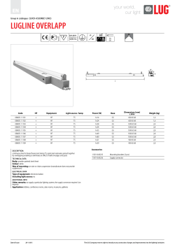


© Copyright 2026