
A 1 2 G
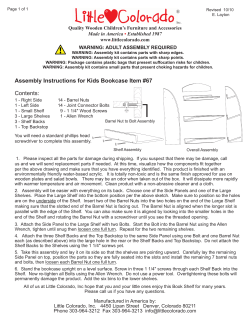
Expedient Homemade Firearms
A 12 Gauge Pistol
The ultimate homemade defence firearm.
11
COMPONENTS
1. BARREL LOCK SPRING
2. BARREL (28.58 x 4.06)
3. RECEIVER (34.93 x 3.25)
4. TRIGGER STOP
5. TRIGGER (8mm Allen Key)
6. TRIGGER SPRING/BOLT
7. SEAR (1½” Washer)
8. COLLAR
9. SEAR SPRING/BOLT
10. STRIKER ASSEMBLY
11. HOSE CLIP
1
2
3
4
10
5
6
9
7
Copyright P.A. Luty
8
www.thehomegunsmith.com
1
Expedient Homemade Firearms
BREECH BLOCK DIMENSIONS
(Drawings in this document are not to scale or proportionate.
Refer to measurements for actual dimensions)
The breech block is the only section of the pistol which cannot be
made by hand. This component must be machined to the following
dimensions using a lathe. A section of round steel bar is required,
Figure ‘A’, 101mm in length and 28.5mm in diameter. The recess
(Hole) to accommodate the Striker (Figure ‘B’) is 12.70mm (1/2”) in
diameter and drilled to a depth of 95mm. The remaining length (Firing
pin hole) is drilled to a diameter of 2.5mm.
The entrance to the striker recess, (Figure ‘C’) is enlarged and tapped
to accept a short 5/8” diameter hexagon head bolt.
A.
ROUND BAR
101mm x 28.5mm
(4” x 1-1/8”)
28.5mm
Firing Pin Recess Dimensions
B.
2.5mm
12.70mm
Tap hole to accept bolt.
C.
2
Expedient Homemade Firearms
STRIKER ASSEMBLY
The Striker is nothing more than a section of 8mm diameter bolt with
the threaded section removed. When shortened, the bolt should be 4
¾” in length. The bolt head must be of the round variety with an allen
key socket. The diameter of the bolt head must be measured. The
one I used was ½” in diameter and so the striker hole was machined
to a diameter of ½” to accommodate it. The bolt used for the striker
must be no heavier than 8mm in diameter.
A 2mm diameter hole is drilled in
the centre of the bolt head to a
depth of 5/8”. The firing pin is a
section of 2mm diameter drill
shank 25mm in length. The pin
should protrude 1 to 1.5 mm from
the face of the bolt head when
inserted. The pin is retained
using bearing adhesive.
Hole
Insert pin
Bolt head
Pin
Striker with pin fitted
3
Expedient Homemade Firearms
STRIKER RETAINING BOLT
The striker retaining bolt is the next component to make. This bolt
screws into the rear of the breech block and holds the striker
assembly in place.
The bolt consists of a short 5/8” diameter hexagon head bolt. A hole
of 8mm diameter must be drilled through the exact centre of the bolt
to allow the striker to pass through it. This is best carried out using a
lathe but it can be done by hand if enough care is taken.
The striker spring should be coiled from 20 gauge spring wire around
an 8mm diameter mandrel. The finished spring should be just under
½” in diameter and 4” in length.
Drill 8mm hole
THE STRIKER READY FOR ASSEMBLY
Bolt
Collar
Spring
Striker
Sear
4
Firing Pin
Expedient Homemade Firearms
ASSEMBLING THE BREECH BLOCK
AND STRIKER ASSEMBLY
Spring
Firing Pin
Bolt
Striker
Collar
Sear
Breechblock
B.
A.
Screw in the retaining bolt ‘A’ and check all parts are moving
smoothly.
With the striker and breech block assembled the firing pin should
protrude 1 to 1.5mm from the block face, as shown at ‘B’ above.
5
Expedient Homemade Firearms
RECEIVER CONSTRUCTION
The receiver is an 11” length of 34.93 x 3.25 mm (1-3/8”) seamless
tubing. Before we can fit the breech block and striker assembly, a
loading port and two holes must be cut into the tube to the following
dimensions.
The first step is to draw a line down the centre of the tube and then
mark out the position of the port, to ensure the three holes are cut in
alignment, as shown in Figure ‘A’ below. The first hole to cut is the
loading port. The port is 145 mm in length and 25mm in width. It is
positioned 110 mm from one end of the tube, this end now being the
breech.
Loading Port
Breech
A
145mm
110mm
Barrel lock hole
12 mm
64mm
B
The next step is to drill two holes. The two holes will accept the ‘sear
spring’ and ‘barrel lock spring’ in due course. The sear spring hole is
drilled 64mm from the breech end, and is 6.5mm in diameter.
The barrel lock spring hole is drilled 12mm from the front of the tube, as
shown in Figure ‘B’. This hole is 4mm in diameter and should be 2mm
deep. The hole is blank and must not pass all the way through the tube
wall. This hole will retain the barrel lock spring in position in due course.
6
Expedient Homemade Firearms
FITTING THE BREECH BLOCK
A.
Breech block
The breech block is inserted into the end of the
receiver as shown in Figure ‘A’. The block is
pushed into the receiver until the end of the block
is seated to a depth of 1/8”, as shown in Figure ‘B’
below.
B.
C.
The breech block is then attached
permanently to the receiver by
welding
around
the
entire
circumference of the inner wall of the
receiver, as illustrated in Figure ‘C’.
Weld area.
7
Breech block
Expedient Homemade Firearms
FITTING THE STRIKER ASSEMBLY
With the breechblock welded in place the striker assembly can be
fitted and tested to ensure it is functioning smoothly.
The striker components are inserted
into the breech block in the order
illustrated below. The bolt ‘A’ is then
tightened.
A.
Receiver Tube
Fully Assembled
8
Expedient Homemade Firearms
FITTING THE SEAR SPRING
The receiver is now almost fully assembled except for the sear
spring.
The sear spring is made from a 4 ½” length of ½” x 22gauge spring
steel strip. The spring provides downwards and forwards tension to
the sear, thus locking the sear in position when the pistol is cocked.
The sear consists of a standard 1 ½” diameter washer with a hole
diameter of 8.5 – 9mm. The spring is formed by bending the spring to
the shape of the drawing in Figure ‘A’ below.
Note; the drawing is only a guide and hand fitting will be required to
obtain the required shape.
½” x 22 gauge flat spring steel
6mm Dia’ hole
10mm
A.
Side View
Down
The receiver is drilled and tapped to accept a 6 or
8mm mm Dia’ socket screw. The hole must not
cut through into the striker hole.
Forward
Rear view of receiver showing sear
spring bolted in place. Note how the
spring applies downwards and
forward tension to the sear.
Sear.
(1 ½” dia’
washer)
9
Expedient Homemade Firearms
FITTING THE GRIP
The pistols grip is nothing more than a 4” (101mm) length of 40 x 20
mm rectangular tube with a wall thickness of at least 1.6mm.
First the top of the grip must be cut to the correct shape so it will fit
the round underside of the receiver tube. The grip is cut to the shape
of drawing ‘A’ so it will be at an angle in relation to the receiver when
welded in place.
Breech view of receiver.
A curved groove must be filed into
the top of the grip so the grip will
match the shape of the receiver.
Cut groove
A.
40 x 20 mm
10
Expedient Homemade Firearms
Cut channel
8mm
After cutting the curved groove
across the top of the grip a square
channel can now be cut to accept
the trigger bar.
The trigger bar is a standard 8mm
‘Allen key’. The channel must be
cut accurately to accept the trigger.
The width of the channel is not too
important but the depth must be
between 8 and 8.5mm
Trigger (Allen Key)
The Allen key should be tested in
the grip at this point to ensure it will
slide back and forth through the
channel smoothly and is a snug fit.
If no adjustments are required the
grip is ready to be welded to the
receiver
11
Expedient Homemade Firearms
The grip is positioned 19mm (3/4”) from the breech end of the
receiver as illustrated below.
The grip is welded to the receiver along both sides of the grip.
The channel for the trigger bar must be left clear.
Alternatively the grip can be brazed at the same points.
19
The grip is welded
along both sides.
Weld Area
12
Expedient Homemade Firearms
FITTING THE TRIGGER GUARD
The trigger guard consists of a 110mm length of 15.88mm (5/8”) flat
bar. The thickness of the bar can be anywhere between 2.5 to 3mm
(3/32” - 1/8”). A long slot is cut into the end of the bar. The slot is
9mm wide and is cut into the front wall of the guard before it is bent to
shape; this allows the trigger bar to be inserted into the grip. The
dimensions of the slot are shown in drawing ‘A’. The bar is formed to
the correct shape by bending it at the points illustrated in drawing ‘B’.
110mm
A.
35mm
B.
20mm
35mm
BEND
BEND
The end of the trigger guard should be
shaped to fit the underside of the receiver.
Following bending the
guard should look like the
one opposite. Actual size
shown.
Template
13
Expedient Homemade Firearms
With the trigger guard finished it is ready to be welded to the receiver.
A slot may be cut into the front of the grip to accommodate the end of
the guard.
It is very important that the bottom of the guard is the same distance
along its entire length, in relation to the underside of the receiver,
before it is welded in place, as illustrated below.
Check the distance
between the guard and
receiver is the same.
Weld
Weld
14
Expedient Homemade Firearms
FITTING THE TRIGGER
The trigger consists of a standard 8mm diameter Allen key, available
from any hardware store. The trigger slides into the trigger guard
through the slot we cut earlier in the front wall of the guard.
Before we can fit the trigger it must be modified slightly. The tip of the
trigger must be filed away until it is angular in shape, as illustrated in
drawing ‘A’. It may also be necessary to shorten end ‘B’ to allow it to
slide into the guard.
Trigger (Allen Key)
A.
B.
Slide trigger into
guard and through
grip.
The trigger should be a close
sliding fit within the guard.
15
Expedient Homemade Firearms
The next part to fit is the ‘trigger return spring’, and the ‘trigger stop
screw’.
As the name implies, the trigger return spring ensures the trigger
returns to its correct position when pressure on the trigger is
released. It is simply a short length of 20 or 22 gauge spring steel,
formed into a curve and bolted to the trigger guard in the position
illustrated in Figure ‘A’.
The trigger stop screw consists of a round headed screw or bolt (cap
head) screwed into, or bolted to, the trigger guard at position ‘B’.
A.
With the trigger stop screw
fitted, the gap between the
front of the grip and the rear
of the trigger should be
about 35mm.
B.
35mm
16
Expedient Homemade Firearms
FITTING THE BARREL
The firearm is now almost complete except for fitting the barrel and
barrel lock spring.
The 12 gauge calibre barrel consists of an 11’’ length of 28.58 x
4.06mm (1-1/8”) seamless tubing. The inside diameter of this tube is
20.46mm meaning that a 12 gauge cartridge is almost a perfect fit
when chambered. The tube is cut to the required length and both
ends are polished with sandpaper to remove any sharp edges, etc.
The barrel is then inserted into the front of the receiver. The outside
circumference of the barrel may require polishing before it will slide
freely into the receiver.
After checking the barrel will slide freely back and forth inside the
receiver the barrel should be removed so the position of the ‘barrel
lock notch’ can be marked and cut into the barrel. The barrel lock
spring will fit into this notch in due course to hold the barrel in the
locked position. Measure a distance of 165mm (6 ½”) from the barrels
muzzle and scribe a line. Cut the notch at this position to a depth of
around 1.5mm.
Slide the barrel into
receiver and check it will
slide freely back and forth.
Cut notch (exaggerated view)
165mm
17
Expedient Homemade Firearms
FITTING THE LOCK SPRING
The barrel lock spring is responsible for locking the barrel in the
closed position when the weapon is ready for firing. It consists of a
3 ¾” x ½” length of 18 gauge spring steel, this being slightly longer
than necessary to allow for hand fitting. A 4mm hole is drilled through
the spring in the position shown in drawing ‘A’. The spring is then
formed to the shape of drawing ‘B’. The drawing is not to scale.
A.
11mm
Bend
Pin
B.
The spring is fitted to the top of the receiver and held in place using a
pin and hose clip arrangement. The pin (dowel pin or similar) must be
a tight tap fit. It is tapped into the spring hole so that 1mm is visible
above the spring and 2mm is visible below it, as illustrated in Figure
‘B’. The spring is then fitted to the receiver by inserting the pin into
the blank hole we drilled earlier in the front of the receiver. A hose clip
is then placed over the receiver and spring and thoroughly tightened,
to securely attach the spring to the receiver, as illustrated below.
When the barrel is pushed back, the spring should snap into the slot
in the barrel, locking the barrel closed. To unlock the barrel for
loading or cleaning etc, the barrel is twisted in either clockwise or
anti-clockwise direction. This will lift and disengage the spring,
allowing the barrel to slide forwards.
Hose Clip
The spring should snap into the
notch when barrel is closed.
18
Expedient Homemade Firearms
MARKING THE SEAR NOTCHES
The firearm is now fully assembled except for cutting the striker
safety notch and the sear notch. The safety notch allows the striker to
be placed in the half cocked position. When the firearm is ready to
fire the striker is pulled back to the fully cocked position. The position
of the two notches can only be marked onto the striker when the
weapon is fully assembled.
To mark the position of the safety notch the striker must be pulled
back several millimetres, five or six would be quiet sufficient. With the
striker pulled back to this position place a small mark across the
striker, as shown below.
The fully cocked position can now be marked onto the striker by
pulling the striker fully back and making a second mark.
Pull the striker back by
five or six millimetres and
mark the striker. The
safety notch is cut at this
point.
19
Expedient Homemade Firearms
CUTTING THE NOTCHES
With the position of the notches marked onto the striker we can begin
to cut the two notches to their correct dimensions. The two notches
should be 1.5-2mm deep and must be cut with a reasonable degree
of accuracy.
The two notches must be cut around the entire circumference of the
striker. The simplest way of doing this is using a lathe. However, if a
lathe is unavailable, an ordinary electric drill may be used for this
purpose.
The drill may be clamped in a suitable vice and the striker placed in
the drill chuck. Using this method, in conjunction with a hacksaw
blade and a small needle file, the two notches can be easily cut with
the striker spinning in the improvised drill-lathe.
STRIKER
Safety notch
Sear notch
With the notches cut, the striker can be re-fitted and the weapon
is ready to test fire.
20
Expedient Homemade Firearms
LOADING AND FIRING
To load:
1) Pull striker back to safety position. 2) Turn barrel and slide
forward. 3) Insert cartridge into chamber. 4) Close barrel and ensure
barrel is locked. 5) Pull striker to full cocked position. 6) Squeeze
trigger and hold on tight.
Read warning on Page 23
2) Turn barrel and
slide forward.
3) Place cartridge in
chamber
1) Pull back to safety.
21
Expedient Homemade Firearms
HOW THE ACTION W ORKS
The action is very simple in design.
When the striker is pulled back to cock the weapon, the sear spring
‘A’ pushes the sear ‘B’ downwards to lock the striker in the cocked
position.
When the trigger is pulled the sear is forced upwards, the striker is
released and flies forward to fire the weapon.
A
B
The weapon is
shown here in
cocked position.
22
Expedient Homemade Firearms
WARNING
Assuming that the reader has engaged in the appropriate level of
subservient grovelling, has acquired the licenses, permits and
paperwork to legally construct firearms, and is of otherwise sound
mind, please observe the following notices.
Under NO CIRCUMSTANCES place your hand OVER
THE BARREL MUZZLE when closing the barrel.
If you do, YOU WILL LOOSE YOUR HAND!!
The barrel must only be closed with the striker in the HALF
COCKED position and by grasping the SIDES OF THE
BARREL.
LEGAL STUFF
The construction of firearms in most jurisdictions is illegal.
This material is presented for academic study purposes only.
23


© Copyright 2026