
TFX-500M-800M - Fire Alarm Resources
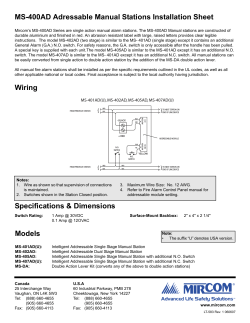
ANALOG, ADDRESSABLE FIRE ALARM
AND VOICE ALARM SYSTEMS
AUTOCALL® TFX-500M/800M
AUTOCALL® TFX-500MV/800MV
Features
Conventional and
Analog, Addressable
Fire Detection
198 Analog,
Addressable Initi
ati
ng
itia
ting
and Output Devices
Plus 1600 Discrete
Inputs or Outputs
(TFX-500M/MV)
990 Analog,
Addressable Initi
ati
ng
itia
ting
and Output Devices
Plus 1100 Discrete
Inputs or Outputs
(TFX-800M/MV)
TFX-500M/MV may
be Expanded to
TFX-800M
TFX-800M//MV On-Site
80 Character LCD
Display; 40 User
Defined Message
Characters
Power-Limited, All
Circuits
Integral LED Zonal
or Group Annunciator
Degrade Mode in
TFX-800M/MV
Operates Evacuation
Signals if CPU
Fa
ilur
eO
ccur
s Be
Failur
ilure
Occur
ccurs
Beffore
or During an Alarm
Smoke Detector
Condition Monitoring
with Automatic
Environmental
Compensation
Individual Smoke
Detector Sensitivity
Selectable from the
Operator Interface
Historical Event Log
for View or Print
Fully Site
Programmable
Solo Test and Alarm
Verification Per
Group or Point
Automatic Time
Control Functions
with Holiday
Exceptions
Six Access Levels
with Unique 0911 Fire
Department Access
Automatic and
Manual Detector
Sensitivity
Adjustment
Alarm Resound by
Zone or Device
andable
Modular, Exp
Expandable
Integral Voice Alarm
and Two-Way
Firefighters
Telephone Option
(TFX-500MV/800MV)
Single, Dual, and Multichannel Voice Systems, 25 and 70 VRMS
Networking Capability
to the Graphical User
Interface From any
TFX Panel
General Information
The AUTOCALL TFX family of self-contained
controls for fire alarm and detection, consists
of the AUTOCALL TFX-500M, TFX-800M,
TFX-500MV, and the TFX-800MV. The
AUTOCALL TFX-500M/MV includes two (2)
analog, addressable signaling line circuits
that provide 99 points each (up to 198 initiating and output devices). The AUTOCALL
TFX-800M/MV adds an expansion motherboard and up to five (5) 2-loop expander
boards. This allows a maximum capacity of
10 signaling line circuits, with 99 points per
circuit, for a total of 990 points. Line Fault Isolation Circuitry is integral to the Signaling Line
Circuits on the Main Processor Board (MP-500),
and the Loop Expansion Boards (IIB-800).
The AUTOCALL TFX family of fire alarm systems reduces complexity by using a common
power supply, main control board (processor),
enclosures, and software. Therefore, the
TFX-500M can be expanded to an -800M on site.
AUTOCALL TFX controls are designed to be
used with conventional or analog, addressable
fire detection devices, in any combination. The
controls are engineered to meet the needs of any
mid to large size building or complex.
The AUTOCALL TFX-500MV and TFX-800MV
provide an optional voice alarm capability and
two-way firefighters telephone communications.
AUTOCALL TFX-500MV/800MV
The AUTOCALL TFX-800M/MV features a
unique multiprocessor design with degrade
mode operation. In the event that an alarm occurs during a CPU failure, visual and audible
evacuation signals will be activated through
the intelligence of the addressable loop expansion modules.
AUTOCALL TFX panels provide flexible operator displays including a backlit LCD and
field configurable LED annunciators. The LED
annunciators provide quick identification of
fire, trouble, and supervisory events by zone,
group, or device, while the LCD provides user
defined text to describe the type of event and
its precise location.
Listings & Approvals
• UL 864 Listed, File S2561
– Local
– Local with Releasing Device Service
– Auxiliary
– Remote Station (Protected Premises
Unit) Proprietary Protected Premises Unit
– Central Station (Protected Premises Unit)
Fire Alarm Control Unit
– Proprietary Receiving Unit
– Central Station Receiving Unit
• CSFM No:
7165-1493:147 (TFX-500M/800M)
7300-1493:152 (TFX series accessories)
7170-1493:167 (TFX-500MV/800MV)
• MEA No. 415-92-E Vol. VI
•
FM ID No. OX2A8.AY
II-227/0902
Page 1 of 6
Description
The AUTOCALL TFX-500M/MV and
TFX-800M/MV are modular by design.
One or more annunciation modules may
be configured into the system for status
indication of points, zones, type of alarm,
or other user selected functions. Switch
modules may be configured for control of
HVAC fans, dampers, door holders, notification appliance circuits, or other control points as required. Enclosures are
available in four different sizes to accommodate all system configurations.
Up to 1600 discrete contact inputs and
voltage outputs in any combination, may
be configured into the TFX system.
These are typically used for audio
evacuation and HVAC control switches,
and annunciation LEDs at the main (or a
remote) control panel.
New and existing, conventional 2- or
4-wire smoke detector circuits may be
completely supervised by the AUTOCALL TFX-500M/MV or TFX-800M/MV.
Conventional circuits are interfaced by
using an IXA-500DMA Addressable Detector Monitor Module or an MDM521
Multi Detector Monitor Module, placed
anywhere along an analog, addressable
communications loop.
The AUTOCALL TFX offers a UL
Listed alarm verification feature for use
with a 900 or 550 series analog addressable detector, or any connected, conventional detector circuit (IXA-500DMA
or MDM521).
Up to seven (7) remote operator control panels may be connected to a
TFX-500M/MV or TFX-800M/MV panel.
These remote panels may be configured
to duplicate the LED and LCD displays,
control switch functions, voice alarm
microphone, and firefighters telephone.
When used with 900 or 550 series analog
smoke sensors, the AUTOCALL TFX panels
provide continuous detector sensitivity monitoring, and automatically compensate for
environmental influences. Alarm and prealarm threshold smoke levels may be defined per device and may be automatically
or manually switched between multiple sensitivities based on the time-of-day, day-ofweek, or date.
Our exclusive CONSYS software configuration tool for site specific user programming easily guides the trained installer through a menu prompted decision process.
The AUTOCALL TFX system logs all
alarm, trouble, and supervisory events
into electronic memory with the time and
date of occurrence. These events may
A.
B.
C.
D.
E.
F.
G.
FIRE ALARM LED—red
TROUBLE LED—yellow
SUPERVISORY LED—yellow
ZONE ALARM LED—red
ZONE TROUBLE LED—yellow
ALPHANUMERIC DISPLAY
NO/DELETE touch-button
H.
I.
J.
K.
L.
M.
N.
SCROLL UP touch-button
SCROLL DOWN touch-button
YES/ENTER touch-button
POWER LED—green
QUIT touch-button
FAST ACCESS touch-button
NUMERIC touch-pad
O.
P.
Q.
R.
S.
T.
U.
V.
KEYSWITCH
PANEL SILENCE touch-button
ALARM SILENCE touch-button
SYSTEM RESET touch-button
DRILL touch-button
LAMP TEST
Control Switch/Status Indicator
Microphone and Fire-Fighters
Telephone
AUTOCALL TFX-800MV Operator Interface
II-227/0902
Page 2 of 6
be displayed on the LCD or
printed.
Coincidence alarm grouping
(cross-zoning) relates multiple
device actuations before confirmation of an “alarm” occurs. The
user may select the number of
successive device actuations (2,
3, or 4) required to trigger an
output response.
The user may assign different
coded patterns to audible and
visual signal circuits. These patterns are typically used to differentiate between “alert” and
“evacuate” conditions. They may
also be used as auxiliary signals,
such as tornado warnings.
Audio A
larm a
nd
Alarm
an
Evacuation
The AUTOCALL TFX-500MV
and TFX-800MV provide single,
dual, and three channel voice
(audio) alarm and evacuation systems.
Tones, recorded voice messages, and
live voice instructions may be broadcast
automatically and manually to selected
zones, for controlled evacuation purposes. Auxiliary tones may also be
broadcast to signal emergencies such
as tornado warnings.
Typically, the messages are broadcast to the areas immediately surrounding the detected fire emergency, e.g.:
the floor of incidence, the floor above,
and the floor below. The message usually begins with a brief alert tone, followed by recorded voice evacuation instructions. In two or three channel systems, different messages are simultaneously broadcast to areas away from
the detected fire emergency.
Other options include redundant
(backup) audio amplifiers, which automatically switch over in the event of primary amplifier failure; distributed amplifiers for large systems; and multiple fire
command stations for control of the system from multiple locations.
Network Communications
Feature
Any AUTOCALL TFX fire alarm control
panel may be connected to the TFXnet
network. Each panel maintains full standalone capability while also operating as
part of the larger system. No master or
AUTOCALL TFX-500M
Shown with 3-module cabinet
host controller is required. True peer-topeer event exchange permits the sending and receiving of event information via
the network, to distribute and coordinate
system wide control.
The network supports a variety of
communication media and wiring topologies. This means that the TFXnet Network may be applied to existing site layouts and wiring schemes, as well as
those employed at new installations.
Refer to the AUTOCALL TFXnet Network
datasheet 228, for more information.
Commissioning and Service
Features
The following AUTOCALL TFX system
features facilitate commissioning and
service:
-Solo test: allows testing of all initiating devices (detectors, pull stations,
etc.) and notification appliances (horns,
strobes, etc.) by one technician.
-Commissioning mode: allows the
system to provide quicker response to
fault conditions introduced to test supervision. This reduces service time and
system life cycle costs.
-Addresses in the base: The 900 and
550 series analog detector heads may
be removed, serviced, and replaced
without reprogramming the system, or
dealing with rotary or DIP addressing
switches. The possibility of duplicate
addressing is virtually eliminated. Optional relay and
sounder bases are also available.
-Service from the floor: The
600, 900, 350, and 550 series
detectors may be serviced from
the floor. Almost any testing or
maintenance function, including
removal and installation of the
detector head, may be performed without a ladder. The
address of the 900 and 550 series analog detectors may be
seen from the floor.
-Detailed diagnostics: are
displayed on the LCD during
alarm, supervisory, and trouble
events to reduce troubleshooting and response time.
-Test reminder: indicates
when the system is due for
scheduled maintenance and
testing.
Remote Functions
The AUTOCALL TFX features an
RS-485 Remote Bus for connection to
various remote operation and display
panels that provide all of the functions
available at the main panel, including
LED annunciator, LCD display, and
control switches.
Other remote bus functions include
remote printers (up to 16) to print a log
of system events, and discrete inputs
and outputs for annunciation and controls. Remote bus functions may be up to
4000 feet (1219.2 meters) away from the
main panel.
System Components
The AUTOCALL TFX-500M/MV and
TFX-800M/MV system components are
identical except for the TFX-800M/MV
Expansion Motherboard and Loop Expansion Board. Each panel consists of a
backbox(es), door assembly(ies), rear
mounted system electronics, and front
mounted system electronics.
Backboxes
The TFX-500M and TFX-800M control
panels use the same family of backboxes in
various sizes. Backboxes may be ordered
separately to allow for electrical “rough-in”
during construction. Rear mounted system electronics are mounted on removable rails and installed in the backbox.
Since the TFX systems are modular,
II-227/0902
Page 3 of 6
backboxes are furnished in 3-, 5-, 7-,
and 10-module sizes. The size is selected
to accommodate specific system requirements, including multiple power supplies, input and output modules, and batteries.
Door Assemblies
Door assemblies, finished in red, are
available in various sizes to match the
backboxes. 3-, 5-, and 7- module sizes are
also available in gray finish.There are two
styles to chose from: Basic and Architectural.
Basic Style doors have a simple metal
frame that houses the front mounted system
electronics. Operator buttons and functions
are accessible without opening the door.
The standard AUTOCALL lock is provided
for access to rear mounted system electronics. A clear acrylic door is optional, for protection of the operator controls.
Architectural Style doors have a styled
door frame and a clear, separately hinged
acrylic door. A dual keyed lock has an
operator’s key which opens the acrylic door
for access to the front mounted system electronics, and a service key which opens the
door frame for access to rear mounted system electronics. The architectural style door
provides a true “dead front”
feature, allowing access to
operator controls, and limiting
access to rear mounted system electronics.
RPS-424
Rear Mounted System Electronics
The RPS-424 and DCPM,
DCPM
AUTOCALL’s solid state electronic power supplies, provide filtered
regulated DC power to the AUTOCALL
TFX series fire alarm systems. The
RPS-424 converts 120VAC primary
power to 24VDC, 5VDC, and 15VDC.
The DCPM converts 24VDC power from
the RPS-424 to the supply voltages necessary for the TFX family. The power
supply monitor modules (models
500PSM and PSM) monitor the RPS-424 and provide visual trouble indicators of faults.
The Multipurpose Interface Module (MPIM)
serves as the communications interface between the main processor and various system
peripherals not on the addressable
loops (i.e. front door displays, switches,
zonal LEDs, printers, auxiliary relays,
etc.) Each MPIM is user defined for the
specific functions of the peripher-als to
be interfaced. The MPIM and associated
peripherals may be used locally or remotely, up to
4000 ft.(1219m) (RS-485
Remote Bus).
The Expansion Motherboard (IAM-800) and
Loop Expansion Board
(IIB-800) are used only
with AUTOCALL TFXIAM-800
800M/MV panels and provide the expansion flexibility for 198-990
points (2-10 loops). Up to five (5) IIB-800
loop expansion boards (2 loops each)
may plug into the IAM-800 motherboard.
Alarm notification appliance circuits on each
loop operate independently if the main procesIIB-800
sor fails for a degraded system operation.
The IIB-800 loop expansion board enables two (2) analog, addressable signaling line circuits. The IIB-800 processes signals received from all devices
on each circuit. Each
IIB-800 is interfaced
via the IAM-800 to the
TFX panel main processor.
Front Mounted System Electronics
The Fire Control Module (FCM-500)
provides common alarm, trouble, and
supervisory annunciation LEDs, as well
as control switches for SILENCE, RESET, DRILL, and
LAMP TEST. Labels
for each control
switch may be field
customized in any
language, or to meet
other site requirements.
The Operator Display Module
(ODM-500) has an 80-character backlit
LCD to display detailed alarm and
trouble messages. An operator’s keypad
allows the user to acknowledge events,
make inquiries, and view the system’s
status. The real time clock and date settings are set and changed from the keypad as well. All functions are password
protected.
Functions available at the ODM-500
include:
- Per point annunciation of alarm and
trouble events
-View and acknowledge events
which have not restored to normal
-Force outputs on
-View smoke detector analog values
in % obscuration per foot, and perform sensitivity checks, per NFPA 72
requirements
-View event history log
-Isolate zones and points
-Enable solo test mode
-Enable commissioning mode
-Print status and
maintenance
reports
-Change smoke
detector sensitivity
16-Indicator
16- and 80-Indicator
Modules
have field
configurable
LEDs for
80-Indicator
annunciation by zone, group, device type, or point.
Since LEDs are bicolored (red and yellow), each LED may be configured to annunciate
alarm and
trouble.
Label
space is
provided with each LED for custom identification.
40x2 Indicator Modules have 80 indicating LEDs in red and yellow “pairs” for
alarm and trouble annunciation by point,
zone, or group. A single label space is
provided for
each pair of
LEDs, for
custom
16 Status Control Module
identification. LEDs
are removable; colors
may be se40 Status Control Module
lected for
specific system requirements.
16 and 40 Status Control Modules
have field configurable switches for control of dampers, fans, zone or point disconnects, and other functions. Switches
are the membrane type. A field
configurable LED next to each switch
may be assigned to indicate the status of
any configurable control point. (The LED
need not be controlled directly by the
adjacent switch.) LEDs are removable;
II-227/0902
Page 4 of 6
colors may be selected for specific system requirements. Label spaces are provided for each switch/LED for custom
identification.
Remote
Operator
Control
Panel
Remote Operator Control Panels provide system operating controls at a remote location. The unit is suitable for
mounting in lobbies, vestibules or anywhere space is a premium. Three configurations are available, each housed
in a small, attractive unit, finished with a
black faceplate and either red or gray
trim. All remote operator control panels
contain a fire control module and one of
the following: an operator display module
(ODM), a 16-indicator module, or a blank
module. Socketed LEDs are also available. Each configuration may be mounted
indoors, either
semiflush or surface.
DirecTone
Voice Options
150 Watt Amplifier
Amplifier Modules provide two (2)
25VRMS or 70VRMS supervised audio
out-put circuits to drive fire alarm speakers. The total power output of each amplifier is 150 watts when used with power
supply P/N 5290-027.
If necessary, the amplifiers may be
wired so that one amplifier may back up
from 1 to 5 main amplifiers. During battery standby, amplifiers may be shut down
automatically to conserve power, until
needed for tone or voice communication.
signal generator module and provide a
variety of alarm signaling tones:
• TM1 WAIL (conventional siren, 5601055 Hz, 11 cycles/min.)
• TM2 YELP (rapid siren, 560-1055
Hz, 3.3 cycles/sec.)
• TM3 HI-LOW (alternating high and
low, 561-760 Hz, 50 cycles/min.)
• TM5 YEOW (descending high to low,
repeated, 545-1296 Hz, 36 cycles/min.)
• TM6 HORN (steady, 470 Hz,
continuous)
• TM7 BEEP (slow intermittent horn,
470 Hz, 50 cycles/min.)
• TM8 STUTTER (rapid intermittent
horn, 470 Hz, 5 cycles/sec.)
• TM9 SLOW WHOOP (slowly ascending low to high, repeated, 424-1163
Hz, 15 cycles/min.
• TM11 TEMPORAL SLOW WHOOP
(NFPA fire alarm whoop, 424-774 Hz,
15 cycles/min.
• TM13 EVAC (amplitude modulated
siren, 479 Hz, 4.3 cycles/sec.)
• TM14 AIR HORN (steady horn, 400800 Hz, continuous)
• TM15 CHIME (single Strike Chime,
musical tone, 49 cycles/min.)
• TM16 PHASER (rapid siren, 600-1200
Hz, 15 cycles/sec.)
• TM17 ALTERNATE HILOW (alternating hi-low,
363 Hz, 518Hz, 60
cycles/min.)
• TM18 WARBLE (extremely rapid
siren, 560-1055 Hz, 6.3 cycles/sec.)
Power Supplies are used with the amplifier modules. P/N 5290-027 provides
8 amps of power at 24VDC.
Digitized Message Modules provide a
digitally recorded custom voice message
up to 40 seconds long. The message
may be configured to play immediately
upon receipt of an alarm, or after a brief
alert tone. The message may be configured to repeat a preset number of times,
or to repeat continuously.
Signal Generator Modules contain
tone/voice generated modules. Plug-in
slots are provided for one fire tone, one
backup fire tone, and two auxiliary tone
generators. The fire tone generator is
continuously supervised for tone output.
If the main tone generator fails, the system
is capable of switching over to an optional backup tone generator. The signal
generator module also incorporates
voice communication inputs for the microphone and digitized message module.
Channel Select Modules (CSM-500)
provide three (3) speaker circuits, Style
Y or Z, rated at 36 watts each. Circuits
may be field configured for 25 or 70 volt
operation. This module includes the logic
circuitry for channel and priority selection
for up to three (3) audio channels. Each
channel is separately switched into one,
two, or all three speaker circuits. Usually
located remotely from the TFX panel, it is
connected to the addressable loop, and
requires the following per speaker circuit:
-One OXA-501SDA plug-in module for
Universal Tone Module plugs into the
single channel systems,
OR
-One OXA-501SDA plug-in module
plus one (1) OXA-503RM plug-in
module for 2-channel systems,
OR
-One
OXA501SDA
plug-in module plus two (2) OXA503RM plug-in modules for 3-channel systems.
Master Communications Modules
(MCM-500) provide a microphone with a
push-to-talk switch for broadcasting live
instructions to selected zones. A master
telephone for two-way firefighters telephone communications is provided as
an option. When provided, the master
telephone occupies the same module
slot on the door assembly as the microphone. Using switches on the Status
Control Modules, the operator may select speaker circuits for broadcast of live
voice instructions, connect to incoming
calls on the firefighters telephone circuit,
and connect any firefighters telephone
directly to any speaker circuit, allowing
broadcast of live voice instructions from
the firefighters telephone system.
Microphone Modules (P/N 5200-524)
provide a microphone with a push-totalk switch for broadcasting live instructions to selected zones.
Multi Detector Monitor Module
The
Multi
Detector
Two MDM521 modules shown
Monimounted on one plate
tor
Module (MDM521) connects zones of
conventional 24VDC detectors and interfaces them to the AUTOCALL TFX
series fire alarm systems. The MDM521
provides eight Class B (Style B) zones.
The MDM521 fully monitors each initiating circuit of conventional 24VDC detectors and signals the control panel
upon alarm, open circuit fault, or power
supply fault. Each zone reports as a
single address to the AUTOCALL TFX
series control panel.
The module is compatible with 2wireor 4-wire, UL Listed, low-voltage,
conventional, point-type detectors or
normally open contact initiating devices.
Up to 30 detectors may be connected to
each initiating circuit, depending upon
the specific detector used.
II-227/0902
Page 5 of 6
ANALOG, ADDRESSABLE FIRE ALARM
AND VOICE ALARM SYSTEMS
AUTOCALL® TFX-500M/800M
AUTOCALL® TFX-500MV/800MV
Digital Alarm Communicator
Transmitter
Digital Alarm Communicator Transmitter (SK5128)
provides 4
reporting channels and dual
phone line
monitor with line seizure. The SK5128
is field configurable to transmit in one of
eight different formats and is used with
SRA-550 supplemental relay assembly.
Specifications
AUTOCALL TFX-500M/MV adn TFX-800M/MV are intended for use within a building interior, free from exposure to moisture,
condensation and excessive dust.
Temperature Range:
32°F (0°C) to 122°F (49°C)
Relative Humidity:
85% (noncondensing)
Analog, Addressable Signaling Lines
Loop Styles:
NFPA 72 Style 4, 6 and 7.* Line isolators optional for short circuit isolation.
Maximum Addressable Points per Loop:
99
Maximum Loops per System:
(2) for the AUTOCALL TFX-500M/MV, (10) for the AUTOCALL TFX-800M/MV
Voltage:
26VDC, 300mA
Supervisory Current:
20mA per loop (plus load)
Alarm Current:
24mA per loop (plus load)
Resistance:
Maximum 75 Ohms per loop
Capacitance:
Maximum 0.5 microfarad per loop
Inductance:
Maximum 1.5 millihenrys (total) per loop
Maximum Continuous Distance:
6500 feet (1981.2m) per loop
Compatible Devices:
IXA-RMS series addressable manual stations
900 and 550 series smoke, duct, and heat detectors
IXA, OXA, 506SDA, CAA-500LI addressable field modules
CSM-500, IXM-500, and OXM-501 motherboards for addressable plug-in modules
IXA, OXA, 505SDA addressable plug-in modules
505SDA/RM and 506SDA/RM agent releasing kits
GARA-1 and GAR-1 agent releasing stations
Remote operator control panels
LX-300 printer
VT520 video terminal
SIM serial interface module
*Complies with Style 7 when a line isolator (CAA-500LI) is connected adjacent to and via conduit, to the input and output of each addressable device. Maximum number of CAA-500LI modules per
addressable loop is 12.
Ordering Information
Contact factory for specific configurations.
Tyco and AUTOCALL are trademarks of Tyco International Services AG or its affiliates in the US and/or other countries.
©2002 TEPG-US (a Tyco Company). All rights reserved.
http://www.simplexgrinnell.com
II-227/0902
Page 6 of 6


© Copyright 2026