
Installation Instructions Model HLIM
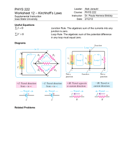
Installation Instructions Model HLIM Loop Isolator Module OPERATION The SIEMENS Model HLIM Loop Isolator Module isolates short circuits on FireFinderXLS analog loops. By placing devices between HLIMs during installation, a short in the wiring within that group is disconnected from the rest of the loop. The remainder of the devices continue to operate. The HLIM BACK FRONT operates in both Class A and Class B circuits. IN - LINE 1 A yellow LED flashes IN - LINE 2 FAULT when a device detects a OUT - LINE 1 short circuit. The HLIM OUT - LINE 2 then isolates that part of the loop. When the short is removed, the HLIM automatically restores Figure 1 The HLIM-1 Loop Isolator Module the loop to normal operation. The HLIM does not have a loop address and therefore does not require address programming nor does it reduce the loop capacity below 252 devices. Remove all system power before installation, first the battery and then the AC. INSTALLATION The HLIM is a polarity insensitive module. Refer to Figure 1 for the location of the two input terminals and two output terminals. Line 1 and Line 2 can be either line of the loop. The HLIM may be used in two circuit configurations as follows: Class B P/N 315-033170-2 (See Figure 2) In Class B wiring each HLIM isolates a branch on the circuit. Note that a short on the main branch causes the entire loop to fail. To prevent this, mount the HLIMs at the FireFinder-XLS enclosure and run each branch independently. Siemens Building Technologies Fire Safety 1. All wiring must comply with national and local codes. 2. In order to provide adequate protection, it is recommended that you do not install more than 20 devices on a single HLIM. 3. Minimum wire gauge is 18 AWG. 4. The total wire resistance (both wires) between HLIMs cannot exceed 20 ohms. 5. Do not install more than 15 HLIMs per DLC loop. 6. All circuits are supervised. 7. Refer to DLC Installation Instructions, P/N 315-033090 for the list of compatible devices. 8. All terminals are power limited. Class A Single Loop 1. All wiring must comply with national and local codes. 2. In order to provide adequate protection, it is recommended that you do not install more than 20 devices on a single HLIM. 3. Minimum wire gauge is 18 AWG. 4. The total wire resistance (both wires) between HLIMs cannot exceed 20 ohms. 5. Do not install more than 15 HLIMs per DLC loop. 6. All circuits are supervised. 7. Refer to DLC Installation Instructions, P/N 315-033090 for the list of compatible devices. 8. All terminals are power limited. Siemens Building Technologies Fire Safety LINE 1 ANALOG LOOP LINE 2 IN IN OUT OUT IN IN OUT OUT IN IN OUT OUT Figure 2 HLIM Wiring Diagram - Class B Installation (See Figure 3) In Class A wiring the HLIMs are wired in series with the loop wiring. This results in a single continuous loop. If any group in the loop has a short, that group is lost and a Class A circuit failure results. The FireFinder-XLS displays communication errors for the devices and a Class A failure for the loop itself. INSIDE ENCLOSURE OUT OUT IN IN OUT OUT IN IN OUT OUT IN IN TO ANALOG LOOP RETURN LINE 2 LINE 1 LINE 1 LINE 2 TO ANALOG LOOP FEED IN IN OUT OUT IN IN OUT OUT IN IN OUT OUT Figure 3 HLIM Wiring Diagram - Class A Installation (Single Loop) 2 P/N 315-033170-2 Mechanical Installation ELECTRICAL RATINGS (See Figure 4) Use a standard 3 1/2-inch deep, double gang electrical switchbox or a 4-inch square electrical box that is 2 1/8 inches deep. Connect the field wiring. Press the HLIM into the box and fasten the module plate to the box. Cover the module front plate with the plate supplied and fasten with screws supplied. Input power: 24 VDC, 1mA max DOUBLE GANG BOX 3 1/2-INCHES DEEP 4-INCH SQUARE BOX 2 1/8-INCHES DEEP SWITCHPLATE 4-INCHES SQUARE (SUPPLIED) SWITCHPLATE 4-INCHES SQUARE (SUPPLIED) Figure 4 Mounting Siemens Building Technologies Fire Safety 3 P/N 315-033170-2 Siemens Building Technologies, Inc. 8 Fernwood Road Florham Park, New Jersey 07932 Siemens Building Technologies, Ltd. 2 Kenview Boulevard Brampton, Ontario L6T 5E4 P/N 315-033170-2


© Copyright 2026