
Fral Manual
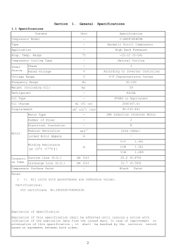
HIGH EFFICIENCY DEHUMIDIFIER WITH TEMPERATURE CONTROL FSDV8000 (Special Version) USER AND MAINTENANCE MANUAL 1. SAFETY WARNINGS This machine is an electric appliance functioning in low tension (230/400V). The installation must be carried out according to the norms and regulations in force concerning the positioning of the machine. Before proceeding with installation, please, read the following safety norms and also all indications and instructions which are written on the machine itself. This dehumidifier must be connected using earthed electrical plugs as required for all electrical appliances; FRAL Company declines any responsibility for any danger or damage whenever this norm is not complied with. Any intervention on the machine using any instrument must be carried out only by a qualified technician. When the machine is connected to power, it must be in vertical position and rough handling must be avoided because it could cause water to come into contact with electrical components. It is therefore recommended to disconnect power before moving the dehumidifier. If water does come into contact with the machine, the dehumidifier must be turned off and can be started up again after 8 hours. Correct Distance: this dehumidifier draws in air from the back and lets it out through the front side grille, therefore the back panel, which supports the air filter, must be kept at a minimum distance of 15cm from the wall. The dehumidifier must not operate in narrow areas, which do not allow a proper diffusion in the room of air exiting the grille. The dehumidifier can be positioned with the sides near the walls. This dehumidifier has been designed and manufactured in compliance with the strictest safety rules. Therefore, pointed instruments (screw drivers or similar) are not to be inserted in the grille or in the opening of the back panel when it is opened to remove the filter. The machine must not be cleaned using water: to clean use a wet cloth. Remember to disconnect the plug from the socket beforehand. The front panel should always be uncovered. The filter should be cleaned periodically (normally every month), but in dusty rooms it should be cleaned more often (see chapter 7). Remember that when the filter is dirty, the air circulation and, consequently, the machines performance will be reduced. 2. PERTINENT TECHNICAL NORMS AND REGULATIONS This dehumidifier has been designed and manufactured in accordance with European Norms and Regulations: MACHINE NORMS (D.P.R., NR. 459 - 24th July 1996); SECURITY REGULATIONS FOR LOW TENSION APPLIANCES 2006/95/CE); ELECTROMAGNETIC COMPATIBILITY (EMC) – 2004/108/CE. It is hereby certified that this Dehumidifier conforms to the: IEC Regulations CEI-EN 60335-2-40, CEI-EN 55014-1, 55014-2. The machine is built according to RoHS European Norms 3. GENERAL SAFETY NORMS During installation or technical intervention, it is recommended to carefully follow all norms written in this manual, and all instructions or warnings indicated. It is necessary to adopt maximum care and attention in complying with all safety norms concerning workers. The cooling circuit pressures and the electric components may cause risks and dangers to the persons during installation or maintenance services. Any intervention must be carried out by qualified technical personnel. Any failure to comply with the norms and instructions container in this manual and any unauthorized. Any modification to the machine will cause immediate cancellation of any warranty. Before proceeding with intervention on the machine, ensure power is disconnected The electric line must be protected by a magneto-thermic differential switch. Do not alter or mishandle the safety devices. Do not spray water on electric parts and motors. This machine must not be installed in explosive or potentially explosive areas. The power connection should be 3 phase. The power connection must be carried out in accordance with the electric diagram. The compressor has only one possible rotating direction; therefore the machine has a device for the control of phase sequences. The compressor will break down if the rotation direction is not correct. Connection to the Condensed Water Draining Connect the condensed water pipe fitting (3/4”) to a draining pipe. Double siphon should be avoided as it would hinder the correct water flow, possibly resulting in flooding. 4. MACHINE DESCRIPTION DEHUMIDIFIERS WORKING DOWN TO 20% RELATIVE HUMIDITY This machine is a special dehumidifier which can control simultaneously temperature and humidity. It is equipped with a particular system for heat recovery before and after the evaporator. This enables the machine to reach very low relative humidity levels with very high energy efficiency and saving that is 30-60% higher than that obtained with traditional condensation dehumidifier. This machine can often replace the use of dessicant dehumidifiers with lower costs and problems. Its structure is in aluminium profiles with enclosed panels in stark galvanized painted steel sheet and has a high efficiency filter and a high displacement motor fan. Its main applications are: where the drying process must be working down at 20% Relative Humidity and 15-20°C. Main components of the machine Coolant Compressor with its own carter electric resistance of 50W. Axial Fan for the dispersion of the heat in excess. Partializing electro valve of the internal condenser (reduces the internal condenser size, if room temperature increases excessively). kW Integrating Electric Resistors becomes operative when the room temperature is getting excessively lower. Humidity control with Relative Humidity sensor which activates the compressor Temperature Controlling System which controls the indoor temperature by activating, in a sequence, the compressor, the partializing valve of the external condenser and external motor fan. 4.1 Important Advice The machine must be connected to power at least three hours before start up. One light, close to the switch breaker shows that the machine is correctly powered. The machine should be started up only after three hours by operating on its specific switch. This delayed start will allow the compressor carter resistors to cause the evaporation of the residual liquid refrigerant which might be inside the compressor oil. The failure to comply with this procedure may cause the breaking of the compressor, invalidating any warranty. 4.2 Functioning of the machine When the machine is in operation, the centrifugal motor fan will be working all the time. The dehumidifier is provided with 3 speeds, but, once the suitable speed is selected by operating on the motor fan terminal boxes, then the speed must not be changed. A 20% relative humidity value and a 27°C temperature value will be preset. Whenever the preset relative humidity or temperature is reached, the compressor will start up. If the temperature drops the electro valve will be activated which will increase internal condensor surface, ensuring a bigger dispersion of the internal heat. If the temperature continues to drop this will activate the electric resistors (optional). Vice versa, if the temperature increases, there will be the disconnection of the electric resistors and of the electro-valve in sequence. Whenever the temperature continues to increase, the external fan motor will be activated. There is a safety thermostat that will bypass the electronic control if the temperature of the external condenser reaches 54°C. In this case the fan motor will go at maximum speed. 5. MAINTENANCE The only periodical maintenance required is the filter cleaning to be carried out weekly. 6. POSSIBLE FAILURES The power light is on, the machine has been started, but main centrifugal fan is not starting working: check phase sequence (light of phase control is flashing). HPS light is ON: reactivate the high pressure meter (failure due to an excess of temperature); if the problem persists, inform the service agent. LPS is ON: Low Pressure Meter intervention. Probably the machine has no pressure. Call the service agent. Water drainage blocked: Check the drainage outlet is not obstructed and no obstructions in the hose. 7. TECHNICAL CHARACTERISTICS FSDV CONDENSED WATER AT DIFFERENT AMBIENT TEMPERATURE AND HUMIDITY CONDITIONS TECHNICAL DATA Rated Power Consumption of compressor (at 30°C, 40% R.H.) Max. Power Consumption of compressor (35°C, 60% R.H.) Total power consumption with Electric resistance and motor fan Max power consumption of Electric resistance Max. current absorbed (at 35°C, 95% R.H.) in standard model 230/1/50 8000 W Room conditions Condensed Water Room conditions Condensed Water 10500 W 25°C-30% 210 l/24h 30°C-50% 460/24h 24W 25°C-40% 280 l/24h 30°C-60% 550 l/24h 12 kW 25°C-50% 340 l/24h 35°C-30% 330 l/24h 36 A 25°C-60% 450 l/24h 35°C-40% 440 l/24h 7900 gr 30°C-30% 300 l/24h 35°C-50% 580 l/24h Defrosting Control System electronic 30°C-40% 370 l/24h 35°C-60% 640 l/24h Hot gas defrosting control system (optional) Condensed Water Draining Pipe Connection (male) Functioning Temperature Range Functioning Relative Humidity Range Water Condensation Capacity (at 35°C - 40 %) Sound Pressare level Lps (at 3 mts in free field) Dimensions,excluding filter:LxDxH cm Net weight Voltage Available: thermost./ electronic Refrigerant R407c 3/4“ 15 - 38 °C 20 -70 % 420 l/24h AIR VOLUME DATA– STATIC PRESSURE OF MOTOR FAN Static Pressure Pa 100 200 300 400 Air Volume 3 m^ /h 8600 8400 8300 8200 8200 8000 500 600 700 72 dB (A) 180x86x200 230 Kg 400/3/50+N 7600 8. COMPONENTS 1) COMPONENTS GENERAL SWITCH LED POWER PRESENCE 2) MANUAL / 0 / AUTOMATIC: I. Manual: In this position the machine is turned on. II. 0: OFF (machine is off) III. Automatic: the machine can be turned on with a remote control through two clear contacts (optional). 3) PHASE: if there is a reversed phase the fuse light is activated. 4) LPS: if there is low pressure because of loss of gas or ice below the battery for example, the LPS indicator is activated. 5) HPS: indicates high pressure inside the refrigerator circuit. 6) HUMIDITY: indicates humidity levels inside the room. When the desired humidity level is reached, the machine will turn off. 7) TEMPERATURE CONTROLLER: The temperature controller will check the inside temperature of the room. If the temperature is too high it will trigger the axial fans to dissipate excess heat proportionally to the temperature inside the room. (The second condenser inside the machine is ducted outside to disipate excess heat). When the temperature inside the room increases it will increase in speed to disipate the excess heat. If the temperature drops the first condesnder inside the machine will automatically activate the electrovalve. This will increase the internal condensor surface, ensuring a bigger dispersion of the internal heat. If the tempertature continues to fall the electronic resistors (optional) will be activated. 8) DEFROST: When the temperature inside the evaporator falls below 0 °C this will start up the battery defrost. If this happens the compressor will be off and the centrifugal fan will be in on position. 9. DIMENSIONS Electric wiring FSDV6000 STD no R.E. FRAL 30 Giu 2012 power RUN HPS LPS PHASE FUSE triac 220 v MOR.9-10 SONDE TRASF.230/24 V 40 v a IC121CX UMIDOSTATO BETA 0-10V ETC-300 TEMP AMB >SET RH31 cliente OR1 R3 R1 OR2 FAN CENT. Comp.01 ELECTROVALVE AXIAL FAN termostato 30/90 set:54°C NO LPS NC NC NO HPS CONFORMITY DECLARATION (European Community Norms for Low Tension and Electromagnetic Compatibility. FRAL s.r.l. Via Industria ed Artigianato 22c – 35010 Carmignano di Brenta – PD – dichiara che: The Dehumidifiers Series FSDV FSDV8000 Comply with the all substantial requirements of the European Community Norms 2006/95/CE of 12th December 2006 concerning safety rules for the Low Tension Electric Products, 2004/108/CE of 15th December concerning Electric Compatibility, 2006/42/CE of 17th May 2006 concerning safety norms for the machines. The Conformity Declaration concerns the following harmonized technical norms: CEI-EN 60335-2-40, CEI-EN 55014-1, CEI-EN 55014-2. With the present certification, it is stated that the product is manufactured according to the RoHS Norms in force, that is, according to Norms 2002/95/CE confirmed with Law Decree nr. 151 of 25th July 2005, art. 5.- Carmignano di Brenta, 21 settembre 2009 Il legale rappresentante Ing. Alberto Gasparini


© Copyright 2026