ABC
docz
Explore
Log in
Create new account
Download
Report
business and industrial
energy
oil
McSnapper® High Speed Tensile with Impact Testing System
PowerPoint ãã¬ã¼ã³ãã¼ã·ã§ã³
Early Bistro Coupon.qxd - Fratelli Ristorante Italiano
Arbor Care Tree Expert Coupon
FREE FREE - Village CycleSport
the coupon here - Murrayhill Little League
$1.00 OFF - Precious Cat
Specials & Coupons - Capri College Iowa
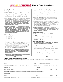
How to Enter Guidelines
Chemistry – Unit 1.2 Worksheet 3
Specials & Coupons - Capri College Iowa
© Copyright 2026
About abcdocz
DMCA / GDPR
Report