
flat-screen tv cabinet © 2013 August Home Publishing Co.
flat-screen
tv cabinet
© 2013 August Home Publishing Co.
Designer Series Project
contemporary
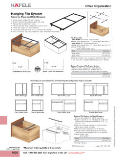
Flat-Screen TV Cabinet
Simple lines, classic joinery, and lots of storage combine
to make this project both functional and great-looking.
Televisions have changed a lot over the
years. So it’s only natural that the cabinets and stands that house them have also
changed. The sleek, low-profile design of
this TV cabinet fits right in with the flatpanel televisions. Your television will look
right at home sitting on top or mounted on
the wall behind the cabinet.
If you look at the photo, you’ll see it’s
wide enough to handle most large flat-screen
2
1
WoodsmithPlans.com
SN08216
WS16918
televisions. And down below, there’s no lack of
space for all your electronic equipment. Behind
the lattice doors, there are adjustable shelves.
The large drawer adds even more storage for
your expanding DVD or Blu-ray collection.
As nice as it looks, what you’ll really appreciate is how easy it is to build. It’s a simple
plywood case trimmed out with a solid wood
top, face frame, and base. And the lattice doors
finish it off for a great look in any room.
©2012 August Home Publishing Co. All Rights Reserved.
©2013
OVERALL DIMENSIONS:
75"W x 20"D x 28"H
-
{ For an attractive option, you can build doors
with frosted glass panels. Check out the video
available at Woodsmith.com.
2
WoodsmithPlans.com
SN08216
WS16918
©2012 August Home Publishing Co. All Rights Reserved.
©2013
a.
c.
b.
building the
d.
Case
The place to start building the cabinet is the case. The main panels
are all cut from cabinet-grade plywood. (I used white ash.) Simple
joinery keeps everything square
and easy to assemble.
BUILDING THE BOX. I started by cutting
the top, bottom, and side pieces to
size. After that’s done, it’s time to get
out the router to start on the dadoes
and rabbets for the joinery.
2
3
WoodsmithPlans.com
SN08216
WS16918
DADoes. The top and bottom will
get dadoes on their inside faces
to house the vertical partitions, as
you can see in the drawing above.
To make sure that the top and bottom dadoes lined up, I clamped
both pieces side-by-side, laid out
the dadoes, and then routed them
with a straight bit.
The top piece had an additional
dado to house the center partition.
So you’ll want to rout this dado
while you’ve got things set up.
TONGUES & DADOes. Now you can
switch to a rabbeting bit and cut
the tongues on the ends of the case
top and bottom, as shown in detail
‘a’ above. While you’re at it, rout a
rabbet on the back edge of the side
pieces for the back panel. Then
change over to a straight bit to rout
the matching dadoes in the two
sides. Just be sure to locate the bottom dado so that you can add the
filler strip (detail ‘b’ above).
Holes. Before gluing up the case,
you can take some time to drill the
holes in the top and bottom pieces
that will be used for attaching the
partition assembly (drawing at left).
You’ll also need to drill holes in the
sides for shelf pins (lower drawing,
page 4). Once that’s done, you can
glue up the top, bottom, and two
sides and then start to work on the
internal partitions.
©2012 August Home Publishing Co. All Rights Reserved.
©2013
a.
b.
Partition AsSEMBLY. There’s nothing
too tricky about making the partitions. The main drawing on page 3
shows how it’s all assembled.
The two taller, vertical pieces are
cut to fit between the dadoes of the
case top and bottom. A horizontal
divider fits in dadoes on the two
vertical pieces. And there’s a center, vertical partition that divides
the upper space.
Partitions. I started by cutting the
two long, vertical partitions to size.
The goal was to get a snug fit in the
dadoes of the case.
2
4
The next thing to do is cut the
dadoes that will house the horizontal divider. Then you can slide the
vertical pieces into the case and cut
the horizontal divider to fit. The last
step is to cut a centered dado on the
horizontal divider to hold the short,
center partition.
Shelf PIN holes. Before fastening
the partition pieces in the case, it’s
a good idea to drill all of the holes
for the shelf pins (drawing below).
The trick is laying out the holes on
WoodsmithPlans.com
SN08216
WS16918
the proper face of the workpiece.
All of the holes are stopped holes
except for those in the short, vertical
partition. These holes can be drilled
all the way through.
Finally, you can glue the partition
pieces into the case and fasten them
in place with screws. Now is when
you’ll want to make sure everything
is square before you move on to adding the face frame.
face frame. The face frame shown
above is pretty straightforward.
What’s nice is you don’t have to preassemble the entire frame and then
try to make it fit. Each piece is cut to
fit and glued in place separately.
I started with the two end stiles,
making sure they were flush on the
outside edges, top, and bottom. Then
you can cut the two long horizontal rails to fit between the stiles and
glue them in place. Next, I trimmed
out the vertical partitions, followed
by the piece that covers the horizontal divider. Finally, you can add the
shorter, vertical piece to the center
partition. Next, you’ll turn your
attention to the base.
©2012 August Home Publishing Co. All Rights Reserved.
©2013
assembling the
Base
With the case complete, you can begin working on the base. As you can
see below, the base is made up of
7⁄ "-thick mitered corner assemblies
8
connected by 3⁄4"-thick rails. This
creates a relieved, or offset joint.
The top edge of the base is rabbeted
to form a reveal — or shadow line
— between the base and case, as
shown in detail ‘b’ below.
Pocket hole screws join the rails to
the corner blocks. You’ll use splined
miter joints to make the corners. And
that’s a good place to start.
CORNER BLOCKs . The four corner
blocks are identical. The grain runs
vertically and a splined miter joint
connects the two pieces. I found it
easier to bevel the edge of a couple of
long blanks and then cut the groove
for the spline on the blanks.
SPLINED MITERS. The box at the bottom of page 6 shows how I cut the
slot for the splines using a standard
blade with a 1⁄8" kerf. Since the joint
won’t show, I used a hardboard
spline (detail ‘c’ below). You can
cut the corner blocks to final length,
then glue up the pairs using the
splines. Finally, you can rout the
shallow rabbet on the top, outside
edge of the blocks.
RAILS. Because pocket hole screws
join the rails to the corner blocks,
you can simply cut the rails to
length. To get the exact length of the
rails, I set the corner blocks on the
case so that the outside faces were
flush with the case. Then it was a
simple task to measure between
them for the length of the rails. I
went ahead and routed the rabbeted
reveal on the top edge of the rails
before moving on.
Once that’s all done, you can fasten the rails to the corner blocks with
pocket hole screws, keeping the
back faces flush with one another
(detail ‘d’). A 1⁄8"-thick spacer helps
with clamping and alignment. Now
you can add the cleats.
CLEATS. You can see below that the
cleats are nothing more than hardwood strips fastened to the inside of
the base. The top of the cleat is flush
with the top of the base.
The length of the cleats and locations of the screws aren’t critical, but
the drawings below give you some
guidelines. After the cleats are fastened to the base, you can attach the
base to the case (detail ‘b’).
a.
b.
d.
c.
2
5
WoodsmithPlans.com
SN08216
WS16918
©2012 August Home Publishing Co. All Rights Reserved.
©2013
a.
adding the
Shelves & Top
The bulk of the work on the case is
done. All you need to do now is add
the shelves and the top.
SHELVES. The drawing above shows
the four adjustable shelves. They’re
simple to make. All you need to do
is cut some plywood panels to size
and glue hardwood edging onto the
front edge of each one.
I cut the edging just a little wide to
slightly extend past the edges of the
plywood. After the glue was dry, I
used a hand plane to trim the edging flush to the plywood. You could
also use a router with a flush trim
bit or a sanding block. Just be careful that you don’t sand through the
thin veneer of the plywood.
GLUED-UP TOP. Now you’re ready
to move on to the top. It’s gluedup from 1"-thick stock. Since it’s
the “crown” of the project, I took
some extra time to sort through the
lumber stack to get the best pieces.
You’re looking for a good color and
grain match between the boards.
The goal is to make your glue lines
as inconspicuous as possible.
SEcTION work. If you have access to
a thickness planer, you can glue up
the top in two sections, run each section through the planer, then glue
up the two sections. This will help
get a flat, smooth top.
2
6
Once you’ve got the entire top
glued-up, you can work on smoothing it. Careful use of a belt sander
can make quick work of flattening
it. Then you can follow up with a
random orbit sander or sanding
block, working your way through
finer and finer grits.
TRIMMING. This top is heavy, so it
would be awkward to trim the ends
square on the table saw. Instead, I
used a straightedge with a circular
saw, as shown in the box below.
After you’ve cut the ends square,
you can sand them smooth with a
sanding block. And while you’re at it,
b.
you can slightly ease all the edges of
the top to soften sharp corners.
ATTACH THE TOP. Now you can fasten
the top through the oversized holes
in the case. This will allow the top
to move with changes in humidity.
Next, you’ll start on the doors and
then add the drawer.
Shop Tips: Splines & Trimming
Cutting Spline Slots. Use the table
saw to cut a straight, clean slot for
the splined miter joints.
WoodsmithPlans.com
SN08216
WS16918
Squaring-Up a Top. To trim the ends of the glued-up
top, use a sturdy straightedge and a circular saw with a
fine-tooth carbide blade.
©2012 August Home Publishing Co. All Rights Reserved.
©2013
STRIP
a.
STRIP
b.
c.
STRIP
STRIP
framing the
Doors
The thing that grabs your attention
right off the bat on this project is
the lattice door panels. The lattice
is really a series of half-lap joints
in strips of wood that are glued
together to form a panel.
This panel fits into a groove in the
rails and stiles of the door frame.
But before you can work on the lattice panel, you need to make the
door frames. They’re made up of
NOTE: To make
glass-panel doors,
see page 12
7⁄ "-thick stock for the stiles and 3⁄ "8
4
thick stock for the rails, as shown
in detail ‘a’ above. And since the
joinery is a stub tenon and groove,
the groove in the stiles need to be
slightly offset from the center.
OFFSET GROOVE. If you look at detail
‘a,’ you’ll see what I mean about
the offset groove in the stiles. It’s
not hard to locate this groove if you
cut the tenon on the rails first. The
box below shows you how I did this
with a 1⁄4" dado blade. It just takes
How-To: Offset Tenon & Groove
Start with the Tenon. Use a 1⁄4"-wide dado
blade to form the tenons on the rails. Flip the
workpiece to center the tenon.
7
WoodsmithPlans.com
Locate the Groove. Position the rip fence
for cutting the groove in the rails and stiles.
The groove in the stiles will be offset.
WS16918
some time to get everything set up
right to get a snug fit.
Now is a good time to put the
pieces for the door frames aside and
turn your attention to the lattice panels. You need to have them in hand
before gluing up the frames.
LATTICE PANELS. It’s not hard to cut all
the pieces for the lattice panels. It’s a
lot of repetitive work, but if you pay
attention, it should go smoothly. The
box on the next page shows you how
I started with wide blanks, cut the
notches for the lap joints, then ripped
the pieces to width.
Gluing Up the DOORS. Once the panels
are complete, you can insert them
in the door frames. But I didn’t glue
the panels in place. I wanted them
to be able to move with changes in
humidity. Now you can go ahead
and glue up the door frames, making sure they’re square.
MOUNTING THE DOORS. Before mounting the doors, you need to add some
mounting blocks for the hinges.
These hinge blocks need to be flush
with the inside edge of the face
frame, as shown in the drawing at
the top of page 8.
©2013 August Home Publishing Co. All Rights Reserved.
Once the hinge blocks are glued in
place, you can mount the hinges on
the doors and set them in the opening. I used 1⁄8"-thick spacers to help
maintain a consistent reveal all the
way around the door.
Next are the door stops. They’re
just hardwood blocks glued in place
behind the face frame. The drawing
on the far right shows the location.
All that’s left to do now is add the
door pulls. Then you can start on the
drawer and back panel.
How-To: Making a Lattice Panel
The trick to making all the pieces
for the lattice panels is to start with
several wide blanks, as shown
on the right. This way, you can cut
the notches for the lap joints all at
once and know they’ll all be lined
up when you assemble the lattice.
Then the strips can be ripped to
width to fit the notches.
CUTTING DADOES. To start off, you’re
really just cutting a series of dadoes
in wide blanks. The trick is to lay
them out accurately. I found it easier to mark the dado location on the
edge of the blank. Then I could align
the marks with the dado blade to
cut the dadoes in a couple of passes.
SETTING UP THE CUT. I used a 3⁄4" dado
blade in my saw to cut all the joints
for the lattice. But to get the right
blade height, I used a scrap piece
that was the same thickness as my
blank. I adjusted the blade height
to cut to the center of the thickness
of the test piece.
START ON THE ENDS. To start things off,
I cut the lap joints on the ends of
the blanks first, using the rip fence
as a guide. Then I flipped the blank
end-for-end and made the same cut.
Now you can move the fence to line
up for the dadoes.
TWO PASSES. Looking at the drawings on the right, you can see how
I aligned my layout marks with the
dado blade. Then I used a spacer
at the end of the blank against the
rip fence to “nudge” the piece over
to make the second cut. Lastly, you
can rip the pieces to width.
2
8
STEP ONE
STEP TWO
Starting at the Ends. Use the rip fence as a
guide to cut the lap joints on the ends of the
blanks with a dado blade.
Align for the First Pass. Use your layout
lines to line up the dado blade to make the
first pass for cutting the dado.
STEP THREE
STEP FOUR
Use a Spacer. To make the 1"-wide dado,
add a 1⁄4” spacer against the rip fence to move
the blank over, then make a second pass.
Rip to Width. Rip the workpieces to width
from the blank. Aim for a snug fit in the corresponding pieces that make up the panel.
WoodsmithPlans.com
SN08216
WS16918
©2012 August Home Publishing Co. All Rights Reserved.
©2013
adding the
Drawer & Back
The last two things to do are build
the drawer and make the back
panel. The drawer fits in the lower,
center opening in the case. It’s
made with simple, rabbeted joints
and finished off with a false front.
You’ll build the drawer first, then
install the metal slides.
A SIMPLE BOX. To start on the drawer,
I cut the front, back, and two side
pieces to final size. Then you can cut
a rabbet on the ends of the front and
back pieces (drawing below).
The next thing to do is cut a groove
on the inside face of all four pieces to
hold the drawer bottom. After cutting the 1⁄4" plywood bottom to size,
you can glue and screw the drawer
box together, making sure that everything stays square.
SPACERS. There’s just one more thing
you need to do before you can install
the metal drawer slides in the case.
I couldn’t mount the metal drawer
slides directly onto the sides of the
case because the face frame overhangs the drawer opening.
To get around this problem, I
made spacers to fit on the sides of
the opening, flush with the edge
of the face frame (detail ‘d’ below).
They allow the metal slides to open
fully without being obstructed by
the face frame. Once the spacers and
slides are in place, you’re ready to
work on the drawer false front.
FALSE FRONT. The false front couldn’t
be any simpler. It’s just a piece of
hardwood sized to fit the opening. The only tricky part is getting
it sized so that there’s an even 1⁄8"
reveal all around. Then it’s just a
matter of fastening it to the front of
the drawer box.
To mount the false front, first put
some double-sided tape on the front
of the drawer box. Then you can
take some time to carefully position
the false drawer front in the opening. You’ll press firmly until the
tape “grabs.” Once the false front
is in position, fasten it in place with
screws from the inside of the drawer.
a.
d.
b.
c.
2
9
WoodsmithPlans.com
SN08216
WS16918
©2012 August Home Publishing Co. All Rights Reserved.
©2013
BACK PANEL. The last piece you’ll
need to add is the back panel. This
is made from 1⁄4" plywood.
The openings you see in the drawing at right provide access to all the
cables for electronic components.
But more importantly, they provide
ventilation to prevent heat build-up.
Shop Notebook on page 11 shows
how I cut clean, smooth openings.
Then I mounted the back panel to
the case using wire brads around
the edge (detail ‘a’).
After going over the entire project
with some sandpaper, you can think
about the finish.
FINISHING UP. I decided to use a
“two-tone” finish for this project. I
chose a dark stain for the top and
base. A natural tung oil finish on the
case contrasts with the dark stain
and adds a nice, warm tone.
To make the task of applying the
stain easier, I removed the top and
base from the case before applying
the stain to those pieces. The case,
shelves, and drawer front were
rubbed with a couple coats of tung
oil. Then you can reassemble everything and apply a clear lacquer finish
for a layer of protection.
Finally, you can move the cabinet
into your favorite room to show it
off to friends and family. After you
install the shelves and all your electronic equipment, just sit back, relax,
and enjoy the show.
a.
Materials, Supplies, & Cutting Diagram
A
B
C
D
E
F
G
H
I
J
K
L
M
N
O
P
3⁄ ply. - 18 x 691⁄
Case Top (1)
4
4
3
Case Bottom (1)
⁄4 ply. - 18 x 691⁄4
3⁄ ply. - 181⁄ x 223 ⁄
Case Sides (2)
4
4
4
Vert. Partitions (2) 3⁄4 ply. - 18 x 211⁄4
Center Partition (1) 3⁄4 ply. - 18 x 13
3⁄ ply. - 18 x 381⁄
Hor. Divider (1)
4
4
1⁄ x 2 - 683⁄
Long Filler Strips (2)
2
4
1⁄ x 2 - 14
Short Filler Strips (2)
2
End Face Frames (2) 3⁄4 x 11⁄4 - 223⁄4
Top/Bot. Face Fra. (2) 3⁄4 x 11⁄4 - 673⁄4
Ver. Face Frames (2) 3⁄4 x 11⁄4 - 201⁄4
3⁄ x 11⁄ - 363⁄
Hor. Face Frame (1)
4
4
4
Center Face Frame (1) 3⁄4 x 11⁄4 - 12
7⁄ x 37⁄ - 41⁄
Corner Block (8)
8
8
8
3 ⁄ x 23 / - 621⁄
Long Base Rails (2)
4
4
2
Short Base Rails (2) 3 ⁄4 x 23/4 - 111⁄4
Q Long Cleats (2)
1 x 1 - 681⁄2
R Short Cleats (2)
1x1-6
S Center Shelves (2) 3⁄4 ply. - 17 x 181⁄4
3⁄ ply. - 17 x 141 ⁄
T End Shelves (2)
4
2
U Center Shelf Edging (2) 3⁄4 x 3⁄4 - 181⁄4
3⁄ x 3⁄ - 141/
V End Shelf Edging (2)
4
4
2
W Top (1)
1 x 20 - 75
3⁄ x 21⁄ - 10
X Door Rails (4)
4
2
7
⁄8 x 21⁄2 - 20
Y Door Stiles (4)
1⁄ x 11⁄ - 16
Z Vertical End Strips (4)
4
2
1⁄ x 1 - 16
AA Vertical Strips (6)
4
BB Horizontal End Strips (4) 1⁄4 x 11⁄2 - 10
CC Horizontal Strips (12)1⁄4 x 1 - 10
1⁄ x 31⁄ - 4
DD Hinge Blocks (4)
2
2
3⁄ x 11⁄ - 21 ⁄
EE Door Stops (2)
4
4
2
1⁄ x 2 - 18
FF Drawer Spacers (2)
2
W
GG
#/4" x 7" - 96" White Ash (4.7 Bd. Ft.)
P
CC
#/4" x 7"- 84" White Ash (4.0 Bd. Ft.)
Z
1"x 7!/2" - 84" White Ash (5.5 Bd. Ft.)
N
Y
Y
GG
HH
!/2" x 7!/2" - 96" White Ash (5 Sq. Ft.)
O
BB
AA
N
N
Q
2
10
• (2) 32mm Door Pulls
• (2) 96mm Drawer Pulls
• (1 pr.) 16" Full-Ext. Drawer Slides
• (2 pr.) Full Inset Hinges
•(16) 1/4" Nickel Shelf Support Pins
• (16) #7 x 11⁄4" Pocket Hole Screws
• (6) #8 x 11⁄4" Fh Woodscrews
• (34) #8 x 11⁄2" Fh Woodscrews
• (18) #8 x 2" Fh Woodscrews
• (1 pkg.) 5⁄8" Wire Brads
!/2" x 7"- 96" White Ash (4.7 Sq. Ft.)
1"x 6"- 84" White Ash (4 boards @ 4.4 Bd. Ft. each)
JJ
GG Drw. Front/Back (2) 1⁄2 x 61⁄2 - 353 ⁄4
1⁄ x 61⁄ - 17
HH Drawer Sides (2)
2
2
1
II Drawer Bottom (1) ⁄4 ply. - 17 x 351 ⁄4
3⁄ x 63⁄ - 361⁄
JJ False Front (1)
4
4
2
1⁄ ply. - 223⁄ x 693⁄
KK Back Panel (1)
4
4
4
WoodsmithPlans.com
N
R
SN08216
WS16918
CC
HH
G
#/4" x 7"- 96" White Ash (4.7 Bd. Ft.) H
I
X
X
X
K
X
DD
FF
EE
J
L
M
ALSO NEEDED:
Two - 48" x 96" Sheets of #/4" White Ash plywood
One - 48" x 96" Sheet of !/4" White Ash plywood
U
V
©2012 August Home Publishing Co. All Rights Reserved.
©2013
tips from our shop
Crisp, Clean Cutouts
The back of the TV cabinet project
needs a cluster of four cutouts to
provide cable access and ventilation.
The drawings at right show how to
make clean, accurate cutouts without
spending too much time and effort.
Layout & Corners. The first step is
to lay out the four cutouts on the
inside of the back panel, as shown
in Figure 1. Next, I formed the
rounded corners by using the layout
to drill 1"-dia. holes with a Forstner
bit (Figure 2). You’ll want to back up
the panel to avoid splintering when
you drill the holes.
Rough cut & smooth. The corner
holes now allow you to use a jig
saw to rough cut the openings. Stay
about 1⁄4" to the inside of the layout
lines (Figure 3).
Finally, to smooth the openings, I
installed a pattern bit in my router.
As shown in Figure 4, a straightedge
attached to the panel with doublesided tape allows you to rout a clean
edge between the corner holes.
11
1
2
3
4
WoodsmithPlans.com
a.
Attach straight edge
along layout line with
double-sided tape
WS16918
©2013 August Home Publishing Co. All Rights Reserved.
Design Option
easy-to-build
easy-to-build
EtchedGlass
GlassDoors
Doors
Etched
Adding
etched
glass
panels
totothe
Adding
etched
glass
panels
the
doors
onon
thethe
flat-screen
TV cabinet
doors
Wide-Screen
TV Cabiis net
easier
than you No.
think.
the
in Woodsmith
169See
is easier
Online
Video,
“Etching
Glass”
at
than you think. See the Online Video,
Woodsmith.com
to
see
how
simple
it it
“Etching Glass” to see how simple
is to
create
a
frosted
looked
on
glass.
is to create a frosted look
(I
(I used
wood
usedthe
thesame
samepattern
patternasasthe
the
wood
lattice
forfor
etching
thethe
glass.)
lattice
etching
glass.)
1
a.
12
2
b.
WoodsmithPlans.com
CUTCUTA ARABBET.
RABBET.ToTomount
mountthe
theglass
glass
panels
you’llneed
needto
panelsinin the
the doors, you’ll
torout
routaarabbet
rabbetininthe
theback
back
of of
thethe
asassembled
door
frame
(Figure
sembled door frame (Figure 1).1).
It’s
It’s
a cinch
to with
do with
a rabbeta cinch
to do
a rabbeting
bit.
ing
bit.
Once
that’s
done,
yousquare
can
Once that’s done, you can
square
the corners
a sharp
up theupcorners
with awith
sharp
chisel.
chisel.
Then
you
can
turn
your
atThen you can turn your attention
tention
to
the
glass
stop.
to the glass stop.
Glass STOP.
Stop.I made
I made
the
GLASS
the glass
glassby
stop
byrouting
first routing
a
stop
first
a small
small
chamfer
on
the
edges
chamfer on the edges of a
of a long,
wide
blank.
Then
long,
wide
blank.
Then
it’s
it’s
just
a
matter
of
ripping
just a matter of ripping the
the thin
strips
on your
thin
strips
free free
on your
table
table
saw.
Figure
2a
gives
saw. Figure 2a gives you
the
the dimensions
I used.
dimensions
I used.
WS16918
Mounting
MOUNTINGThe
THEGlass.
GLASS.Once
Once you
you have
have
the
thestrips
stripscut
cutfree
freeof
ofthe
the blank,
blank, you
you
can
canmiter
miterthem
themto
tolength
lengthfor
for aa tight
tight
fit
fitininthe
theframe.
frame.Then
Then lay
lay the
the glass
glass
panel
in
place
into
the
rabbeted
panel in place into the rabbeted
frame
frame and
and attach
attach the
the glass
glass stop
stop
with
a
few
wire
brads.
with a few wire brads.
Fastening
FASTENINGthe
THEStrips.
STRIPS. II used
used aa nail
nail
driver
to“push”
“push”the
thebrads
brads in
in place
place
driverto
totohold
hold the
the glass
glass stop.
stop. You
You could
could
also
use
a
small
hammer
also use a small hammer to
to gently
gently
tap
tapthe
thebrads
brads in
in place.
place. It’s
It’s aa good
good
idea
to
predrill
the
stop
idea to predrill the stop to
to prevent
prevent
ititfrom
fromsplitting.
splitting. Once
Once that’s
that’s done,
done,
all
that’s
left
to
do
is
clean
all that’s left to do is cleanthe
the glass
glass
thoroughly
thoroughlyand
andattach
attach the
the doors
doors to
to
the
thecabinet
cabinetfront.
front. W
a.
©2013 August Home Publishing Co. All Rights Reserved.
MAIL
ORDER
SOURCES
Woodsmith Store
800-444-7527
Lee Valley
800-871-8158
leevalley.com
Rockler
800-279-4441
rockler.com
13
Project Sources
This TV cabinet is large enough to support most flat-panel, wide-screen television sets and would make a great
addition to an entertainment room.
You’ll find almost all of the materials
needed to build the cabinet at your local lumberyard or woodworking store.
But there are a few items you might
need to order from mail-order suppliers before you begin the project.
Pocket screws were used to assemble the base of the cabinet.
These screws can be found at almost
any woodworking store. I used #7 x
11⁄4" fine-threaded screws (38502)
from Rockler.
You’ll also need some hardware for
the drawers and doors. I used Blum
full inset, 120° self-closing hinges
(00B15.24) to mount the doors. And
installed a set of 32mm (01X43.22)
and 96mm (01X43.24) pewter double
bar door pulls for opening the drawers and cabinet doors. A pair of black
16" full-extension slides (02K36.16)
was used to mount the large center
drawer. All of this hardware was ordered from Lee Valley.
WoodsmithPlans.com
WS16918
©2013 August Home Publishing Co. All Rights Reserved.


© Copyright 2026