
Toasty Toes 2011-12 Next Generation Ski Boot Warmer Final Report
COMFEET CORPORATION LTD.
Research & Design Team
2011-12
Toasty Toes
Next Generation Ski Boot Warmer
Final Report
Comfeet Corporation Ltd. has an
opportunity to innovate in the space of
ski boot foot warmers. Current designs
have two main problems, namely
inconvenience with batteries and
necessity for “always on” operation,
leading to suboptimal transient
performance. We have designed an “ondemand battery-less” foot warmer to
remedy these issues. Design constraints
for necessary heating power are found
by finite element analysis and nonlinear
optimization, and subjective design
criteria are derived from survey
responses. Finally, the construction of a
beta prototype is discussed, and
marketing considerations are taken into
account.
Pulkit Agrawal, Gyu Jin Ahn,
Luree Brown , Alex Burnap
University of Michigan
12/13/2011
Table of Contents
NOMENCLATURE ..................................................................................................................................... 3
INTRODUCTION ........................................................................................................................................ 4
Need and Want................................................................................................................................. 4
PREVIOUS DESIGNS .................................................................................................................... 4
DESIGN CRITERION..................................................................................................................... 6
Finite Element Analysis ................................................................................................................... 7
Subjective Design Criteria ............................................................................................................... 8
CONCEPT GENERATION........................................................................................................... 10
Pull Cord & Electro Conductive Fabric Concept........................................................................... 10
Rechargeable Battery Inside The Insole ........................................................................................ 11
Chemical Insole ............................................................................................................................. 11
Heat Application ............................................................................................................................ 12
Attachment to Ski Boot.................................................................................................................. 12
PRODUCT DESCRIPTION ....................................................................................................................... 13
Final Concept ................................................................................................................................. 13
ENGINEERING FUNCTIONALITY ANALYSIS .................................................................................... 15
Design Modeling............................................................................................................................ 15
Engineering Design Optimization.................................................................................................. 17
Overall Utility Optimization .......................................................................................................... 18
EMOTIONAL AND AESTHETIC ANALYSIS ........................................................................................ 21
Beauty in Design ............................................................................................................................ 21
Analytical Craftsmanship in Product Design ................................................................................. 22
Kansei (感性) Design .................................................................................................................... 25
MICROECONOMIC ANALYSIS ............................................................................................................. 28
CBC (Choice Based Conjoint) Studies .......................................................................................... 31
Logit Model ................................................................................................................................... 31
MARKETING ANALYSIS ........................................................................................................................ 33
Investment:..................................................................................................................................... 33
Five Year Plan ............................................................................................................................... 34
Net Present Value Analysis ........................................................................................................... 34
Break-Even Analysis ..................................................................................................................... 35
Development Tradeoffs ................................................................................................................. 36
1
Sales Sensitivity Analysis .............................................................................................................. 36
Marketing Strategy......................................................................................................................... 37
PRODUCT DEVELOPMENT PROCESS ................................................................................................. 38
Concept Generation ....................................................................................................................... 39
Alpha Prototype ............................................................................................................................. 39
Beta Prototype................................................................................................................................ 39
Final Product .................................................................................................................................. 40
Business Plan ................................................................................................................................. 40
Product Development Process ....................................................................................................... 41
Project definition: .......................................................................................................................... 41
Concept Generation: ...................................................................................................................... 41
Final Product: ................................................................................................................................. 41
Production, Marketing, and Distribution: ...................................................................................... 41
CONCLUSION ........................................................................................................................................... 42
REFERENCES ........................................................................................................................................... 43
APPENDICES ............................................................................................................................................ 45
2
NOMENCLATURE
Engineering Functionality
B: Magnetic Field Strength
V: Voltage
ω: Angular Velocity
r: Radius
P: Power
Marketing
Q: Demand
Θ: Theta (Intersection on Demand axis on demand curve)
λp: Price elasticity of demand
λd: Attribute elasticity of demand
P: Price
R: Revenue
C: Total Cost
Cf : Fixed cost
Cv: Variable Cost
Π: Profit
T: Transient Heating Time
r: Rate of return or discount rate
3
INTRODUCTION
Need and Want
One of the first extremities to lose heat in cold climates is the feet. While performing outdoor
recreational activities in the cold, feet are susceptible to cold temperatures. This causes the
experience of having fun outdoors into a less enjoyable experience causing people to stop skiing
to warm up earlier than they would like to. Studies show that there is a direct correlation between
the duration of time in the cold and discomfort levels [1]. Thus our problem is presented, how to
keep feet warmer while skiing, so that skiing can be benefited from for longer periods of time.
Exposure to the cold can lead to a loss of manual dexterity and tactile dexterity sensitivity.
However, simply heating the foot presents problems. If you heat the foot without heating the rest
of the body, this could create a decrease in core temperature due to body’s thermoregulatory
response to the cold. This is due to the fact that feet act as cold sensors to help keep the body’s
temperature constant even in different temperature climates. Thus, this presents a constraint to
our problem. Not only do we have to heat the foot but we must make sure to not excessively heat
the foot so that the thermoregulatory system disrupts the temperature control of the rest of the
body.
The people who will benefit from our design are skiers, especially older skiers. It has be shown
that there is a direct correlation between age and the length of time it takes to feel discomfort due
to cold temperatures [1]. Skiers will enjoy the experience of skiing a lot longer by using our
design which will result in the increase of the overall happiness of our user.
In the current market there are many designs that generate heat for feet. These are outlined
further in the remainder of the report. All the current designs however, are very expensive; use
battery generated power and is not fully applicable to ski boots. Our design is very inexpensive
and is not battery operated. To power our design the user pulls the cord for the amount of heat
that is desired. Although many components of our design were pre-manufactured, these
components work together in a unique way.
Once we gathered all our components, we decided that we needed to generate more power. We
then maximized the power, by optimizing the pull cord in our design. After finalizing our design
we then performed analysis on the model, economic, emotional, marketing and functionality.
PREVIOUS DESIGNS
The following table shows all the lateral products that our product was compared to. The
majorities of the designs are battery operated and take long periods to recharge. All the designs
vary in weight and size. Some of the designs have many consumer complaints about the battery
swelling or overheating. Also many of the consumer complaints were concentrated on the lack of
heating in cold temperatures. Refer to the Appendix A for a detailed list of consumer reviews.
4
Existing Product review and Market research
Picture
Price
Spec
$30.94
Factory
overhead Cost;
$2.5~2.7 for
each insole
• Two AA batteries for each
• Leg strap holds AA batteries
• Remote cord
Cozy Feet Heated Insole
$99.95
Factory
overhead Cost;
No information
• Weight: 0.7 lbs.
• Battery Requirements: Rechargeable
• Lightweight
• Durable
• Long battery life
• Simple controls
Thermo Sole
$59.95
Factory
overhead Cost;
No information
• 12V heated boot insoles
• PU foam construction
• Superior support, shock absorption
and feedback
• Anatomic contoured design provides
optimal support of your foot
Venture Heated Insole
•
$39.99
Factory
overhead Cost;
$2.5~2.7 for
each insole
•
•
•
•
LEADFAR
5
Three AA batteries for each insole
with separated battery box, which can
be tied to ankle
Equal in heating distribution,
temperature is about 42 deg. C
Power: 1.5 to 2W each
Size: 36 to 46
Voltage: 4.5W
$39.99
Factory overhead
Cost;
$3.0 for each
insole
•
•
•
•
•
Hygea
$49.99
•
Factory overhead
Cost;
$3.5~3.7 for each
insole
•
•
•
•
•
•
Heatact
FIR carbon fiber inside the heating pad
Semi-conductor electric chips, fast
warming and insole temperature could
be controlled in 38 to 50°C
3.7V DC lithium battery for
rechargeable
Long lifespan: battery can be
recharged for more than 600 times
Light and small, easy to carry: with a
weight of only 89g, the battery is very
light and small
Uses 3, 12 or 24V DC, or 100 to 240V
AC
Temperature: around 45oC
Maintenance time: 8 to 10 hours
Flexible and can be bended
Battery capacity: 2.6Ah
Battery component: Ni-MH or alkaline
battery
Battery recharge time: at least four
hours
DESIGN CRITERION
Our problem of how to keep feet warmer while skiing, so that skiing can be benefited from for
longer periods of time. After researching the current market we came to the conclusion that there
are many different heated applications that can be used. However all the current designs are
battery powered, so we concentrated our solution on making a design that did not use battery
power. Therefore we decided to refocus our problem to not only making feet warmer by skiing
but also being a battery-free design.
Conceptualizing the design of an innovative boot must be built upon a solid foundation of
measurable design criteria. We have addressed this issue in a two-fold manner.
First, a finite element analysis was carried out to simulate the heating requirements necessary to
keep a foot warm in the winter. This effort was necessary for baseline objectivity as it constrains
any design concept for heated boots, regardless of their application (college students,
construction workers, ski lift operators, etc.) Another way of saying this is the weighting
function derived to optimize our eventual design concept is uniformly weighted across all
potential end-users.
6
Second, a list of general design criteria subjective to the end-user was developed. The
subjectivity in these design criteria is a result of being unequally weighted between different
market end-users. For example, a college art student might be more heavily weighted towards a
fashion heavy design than a more utilitarian oriented engineering student. It is important to note
that while this data is subjective to the particular market niche, it does not mean this data is
subjective in the sense of being unquantifiable.
Finite Element Analysis
A 2D finite element analysis was conducted to get a rough order of magnitude estimate for the
amount of heating power required, either generated by a heating source or retained with better
insulation.
2D Finite Element Analysis of Boot without Heat Source
Figure 1: A 2D finite element analysis was conducted of the boot without heat source.
The entire boot with foot is shown plotted with a temperature gradient color scale. Assumed
environmental conditions are -5℃ ambient temperature and 37℃ body temperature.
Without an external source of heat, the simulated foot had an average sole temperature of 2℃in
equilibrium with the environment at -5℃. This exemplifies the need for some sort of heating
device, whether passive or active.
2D Finite Element Analysis of Boot with Heat Source
Figure 2: A 2D finite element analysis was conducted of the boot with heat source.
7
The entire boot with foot is shown plotted with a temperature gradient color scale. Assumed
environmental conditions are -5℃ ambient temperature and 37℃ body temperature. It was
found that the necessary steady state temperature of the warmer be 24℃.
To achieve the desired 25℃ at the skin surface of the foot sole, it was found that the heating
element must maintain 24℃with a 2.5 mm thick wool sock in between.
The goal of this 2D finite element analysis was to find the approximate amount of heating power
required to sustain the surface of the foot sole skin at 25℃. This was found by integrating the
heat transfer from the heating element over all the nodes at the interface of the temperature
gradient of the heating element.
The average heat flux was found to be 54.9 W/m2.
Combining the average heat flux with the boot sole footprint of .0235 m2 resulted in a steady
state power draw of 1.29 W.
All supporting documentation and equations are found in Appendix B.
Subjective Design Criteria
Aesthetically Appealing
One of the many reasons why people do not like to purchase retrofits is because they are not
aesthetically appealing. It is apparent that there has been something added to the product which
makes the product look weird and not designed as one consistent unit. A goal for our design is to
make certain that it does not interfere with the aesthetic appeal of the ski boot. We will measure
the aesthetic appeal through customer feedback and surveys.
Comfortable
It is important that we pay special attention to the comfort level. Since comfort is a psychological
state, this criterion will be hard to measure. Our target goal will be to increase the padding in the
sole of the average winter shoe by 50%, while minimizing the weight.
Cost
Another important criterion is the cost of our product. In the current market, heated boots are
more expensive than regular ski boots. We will select material that is less expensive. We will be
able to fulfill this criterion by using recycled materials and developing a cheaper manufacturing
process. Our target cost to manufacture one pair of our product is $80, based on the average price
of the previous concepts minus the average profits.
Durability
We would like to maximize the longevity of our product. On average people purchase one pair of
ski boots and they last for a long time. Our goal is to develop a product that will maximize the
longevity so our customers will not have to replace them often. To measure the longevity of our
8
design we would need to calculate the stress and wear on each material. We aim to have our
design increase the longevity to 15 years.
Reheat Ability
Another important aspect of our design is reheating ability. Our design needs to be able to be
reheated easily. This criterion will not have to be measured. Simply our design will either meet
this criterion or not.
Easy to clean
We would like to conceive a design that is easy to clean. We will focus on a design that can be
cleaned by simply wiping off dirt with wet paper towel. To meet these criteria, our design would
need to minimize the water absorption of the outermost material.
Weight
The weight of the average ski boots ranges from 10-15 lbs. We would like to minimize the
weight of our design so that it is nearly negligible compared to the weight of the ski boot;
therefore our target weight is less than 1 lb.
Material
We would like to use materials that have been recycled. This meets with our goal of producing a
sustainable product. We would be able to measure this by the number of different types of
recycled material that will be included in the design. Our design goal is to have 90% of the
material used be recycled and reusable material.
Water resistant
It is important for our design to be water resistant. One way we could ensure that our design
meets this criterion would be to dispensing the same amount of water on each of the various
materials and measure the amount of penetration of water into the material. Our target goal is
minimize the penetration of the water into the material.
Sustainable
The most important aspect of our design is sustainability. We would like to create a design that
helps the environment by reducing waste, benefits society by fulfilling a need, and boosts the
economy in which our design is produced. Although sustainability is hard to measure, our target
goal is to meet many of the sustainability requirements from the current sustainability standards
required by the United Nations.
Universal
We would like to conceive a design that is compatible with the majority of ski boots. This design
would then align with our goal of being universal, the ability to be used in conjunction with other
products that help make the user warmer. To measure this we would have to refer to our
benchmarking research and analyze if our design can be used with a variety of other products.
9
To solve our problem our hard constraints include cost, material, sustainability, comfort level,
reheat ability and universality. Our soft constraints, that are to be considered however do not
adhere to the functionality of our design are aesthetic appeal, traction, ease of cleaning.
CONCEPT GENERATION
Pull Cord & Electro Conductive Fabric Concept
Another design domain would be to transfer energy from an electric power source, either
generated or stored, through a resistive heating element. To satisfy the design criteria outlined
earlier, any concept in this domain must fulfill the constraint of minimum power transfer, while
still being primarily comfortable, durable, and cheap.
To this end, a choice resistive element would be in the form of a resistive fabric. Many such
fabrics exist, usually by the name of electro-conductive textiles. Examples of such are Gorix,
Bekinox, and Shieldix. These fabrics would be able to be incorporated into existing boot designs,
or made into universal retrofits such as an outer sock layer, shoe insole cover, or cup of fabric
around the toe area.
To power this resistive element, a battery pack would be incorporated into the boot, or retrofitted
to clip onto the outside of the boot. This could be coupled with a switch so as to give the end user
control of when he or she wanted to apply heat. Using a battery pack is a standard idea, but has
its faults, as it require the end-user to consistently keep the charge of the battery at a usable state.
Often times heat to the feet is only needed for brief stints of time, particularly when the mobility
of the user happens in cycles. Examples of such cases are a construction worker taking a work
break after a couple hours of physically demanding labor, or a skier on the 15 minute ski lift after
a rigorous downhill run. For these particular cases, a battery pack may not be needed, and may
be instead replaced with a power generation device. Our concept for this device is an
electromagnetic generator with a rip-cord, much like the pull-start for a lawn mower. In theory,
this device would be able to harness the power from the impulse of a human pull, smooth it out
with simple passive circuit elements, and deliver the power to the electro-conductive textile. An
example of what this system might look like is shown in Figure 3.
Figure 3. Pull cord & electro conductive fabric concept
10
Rechargeable Battery Inside The Insole
Figure 4
Figure 5
This concept consists of a rechargeable Lithium ion battery inside the insole. The battery can be
charged using an adapter when not in use through a slot at back of the insole. Between the top
and bottom layer of the insole the batter and the heating element connected to it is placed. The
CAD model of the concept is shown in the figure above. This concept has the advantage of easy
installation and easily replaceable but can be uncomfortable to wear as the battery is placed near
the heel area.
Chemical Insole
This concept is a chemical insole that releases heat when compressed. It begins as a gel
substance when inserted in a shoe, and over the course of the day, turns into a liquid substance.
To rejuvenate, the insole must be placed in a cooler setting like a refrigerator or freezer, so that
the liquid can solidify back to its original state. For people who are shorter and have smaller feet,
there will be a thicker pad that requires less force to release heat. One of the issues of the design
is making sure we can adjust the chemical substance so that it will take the same percentage of
force to activate. A solution for this would be to add springs and make the insole two layers with
springs in between them. There should also be a dial so that the user can adjust the tension in the
springs, to regulate how much force is needed relative to the desired heat released.
One of the negative aspects of this design is the lack of force to activate the chemical around the
toe area. We would have to think up a solution to be able to activate the chemical around that
area. Since toes are separate extremities on the feet they often get the coldest the quickest.
Our concept selection process start from we need power generation, however there are thermal
insole that use battery on the market and people don’t like battery operated insole because it is
not long last in the cold skiing area. Therefore, we decided that our thermal insole system use
mechanical hand crank generator even though it is not comfortable use compare to battery
operated thermal insole. But it is reliable and can use when customer wants hit up their feet.
Concept classification is easy to view with Figure 6.
11
Figure 6
Heat Application
Toes lose heat the fast in cold conditions. This concept was generated with the goal that the heat
around the toe area should be maximized. The toes are completely enclosed with heating coils on
the bottom and top of the enclosure (Figure 7). To secure the enclosure to the foot, a small heel
attachment is used. At the back of the heel attachment there is a USB connection that will be
connected to the selected heat generated concept.
The front enclosure is made out of a thin polycarbonate layer insulated with Thinsulate ®. Inside of
the front enclosure the heating element is made out of copper wires. These wires extend underneath
the enclosure towards the USB connection. The USB connection is made out of ABS, and will be
purchased pre-assembled. The heel attachment is made out of flexible polymer foam and attached
to the base of the product.
Figure 7. Toe Enclosure
Attachment to Ski Boot
The pull cord heat generation will be attached to a bracket that wraps around the top of the ski boot.
It is adjustable so that it can fit around many different types of ski boots (Figure 8). The dimensions
that were used for the CAD model were taken from the current ski boot. The bracket will be made
out of aluminum and polyoxymethylene. These materials ensure that the bracket will be flexible so
that it can adjust around many different sizes of ski boot while being stiff enough to be able to hold
the weight of the pull cord attachment.
12
Figure 8
Figure 9
PRODUCT DESCRIPTION
Final Concept
Our final concept is a heating insole system which includes an insole with heating element and
wire connected to the hand crank pulling cord motion generator, the Yogen®. The Yogen® is
located outside at the top part of the ski boot inside the bracket. Figure 10 shows our fully
functional Beta prototype. This design was generated based upon taking the best elements from
most of our concepts and combing them so that they could work together into one system.
Our bracket is designed so that you can place the Yogen® on the outside or on the back of the ski
boot, for additional customization. However it is easier to use on the outside of the leg, as shown
in the picture below. After the user attaches the bracket all they have to do is plug in the cord
from the insole into the generator and then the product is ready for use.
To operate our product, after connecting the wires from the insole to the Yogen® , the user would
have to pull the hand crank up in a motion similar to starting a lawn mower. The user would
repeat this motion until they feel the heat desired. It is important to note that there is a maximum
heat value that can be generated because of the constraints of the Yogen® and the effects of the
thermoregulatory system.
13
Figure 10 Beta prototype
Table 5 (pg. 28) shows all the material that will be used in our product.
This final product correctly aligns with our problem of providing battery free on demand heat for
skiers so that they can enjoy skiing longer than ever before. This design meets all of our hard
constraints of cost, material, sustainability, comfort level, reheat ability and universality. The
remainder of the report will discuss how we optimized our design to meet all our criteria.
14
ENGINEERING FUNCTIONALITY ANALYSIS
The engineering design process for Toasty Toes consisted of three steps.
I.
Design Modeling- An off-the-shelf electromagnetic pull cord generator of similar design
to what we needed was reverse engineered and mathematically modeled.
II.
Engineering Optimization- Extrapolations on our mathematical model were made to
study the effect that increasing heating power output had on the dimensions of principal
components.
III.
Overall Utility Optimization- Using survey data, utility tradeoffs between material cost,
physical size, and power output were made to optimize for a final design.
Design Modeling
Our first goal was to characterize the current performance at its average output of 5 Watts, and
then simulate what changes we could make to our system to increase the power output. A stock
Yogen pull cord generator was disassembled and reverse engineered. The most relevant
components to this power generation system are the pull cord, the gear system, and the
flywheel/magnet assembly coupled to a set of coils as shown in Figure 11. The current radii are
shown in Table 1.
Figure 11 Gear-Magnet Schematic TOP VIEW
Table 1
Radii of Yogen Pull Cord Generator
Main Gear 1
16.5 mm
Gear 2
7.5 mm
Gear 3/Magnet Gear
3 mm
15
We next needed to understand how the actual generator portion works. As shown in Figure 12,
we notice that the pair of rotating magnets generates an electromotive force, and thus generated
power, across a stationary plane of coils.
Figure 12 Gear-Magnet Schematic SIDE VIEW
This arrangement is in fact the same as Michael Faraday’s first generator setup, also known as
the homopolar generator, and in its ideal case is governed by Equation .1. B is the strength of the
magnetic field.
Vout =
2
Bωmagnets rmagnets
2
(0.1)
But we know the angular speed of the magnet from the pull cord. We write the radius of the big
gear as a variable to be optimized later.
ωmagnet = (
1
16.5 7.5
)(
)( )v pull cord
rGear 1 7.5 3
(0.2)
The last relevant equation is the relation between electric power and voltage.
Pout =
2
Vout
Rint ernal + Rload
(0.3)
Combining these equations, we finally end up with
Pout =
4
121 v 2pull cord B 2 rmagnets
2
8rGear
1 ( Rint ernal + Rload )
16
(0.4)
Engineering Design Optimization
Assumptions were made from watching multiple user tests of the Yogen generator to set the
upper limit of vpull cord to 40 cm/s. In addition, the internal and load resistances were measured
and found to be 10 Ohms combined.
The magnetic field of the magnets, determined to be Grade 42 Neodymium, was first
theoretically calculated to be 272 Gauss. Using the known average power output of 5 watts at a
pull cord speed of 40 cm/s, and the gear ratios of the Yogen, we determined the magnetic field to
be 189 Gauss. This lowered value of the magnetic field can be used as an approximation
representing not just the magnetic flux losses, but also other mechanical and electric resistances
within the Yogen unit.
Since our design criteria cited the overall size of our power generating device as most important,
an objective function to be minimized was developed to model the device area with variables as
the radiuses of both Main Gear 1 and the magnets.
This objective function was then constrained by the power requirement in Equation .6. Although
we first started with 5 Watts of output as a reference, we determined 36 peak watts would be the
upper bound for the 5th percentile of male strength [3]. Since the power delivered by a human to
our power generator can be approximately modeled by a sine wave, the RMS value of the upper
bound to our power output is 25 watts.
The objective function with its constraint is shown below, with the power output in watts shown
as a design parameter.
=
minimize Area 2 max{rGear1 , rmagnets } × 2(rGear1rmagnets )
(0.5)
subject to
4
121 v 2pull cord B 2 rmagnets
2
8rGear
1 ( Rint ernal + Rload )
≤
X Watts
(0.6)
Since this constraint is nonlinear, Matlab was used to minimize the device area. Unsurprisingly,
this optimization found a solution by keeping the gear ratio the same, while increasing the radius
of the Neodymium magnets.
17
Figure 13
Note: This analysis did not determine the changing magnetic field strength as a function of
radius, making the assumption that fringe fields and subsequent losses do not occur as a function
of radius.
Overall Utility Optimization
With a sufficient and proper model of our desired power generator, as well as knowledge on its
ability to extrapolate to our heating power region of interest around 25 watts, our final step was
to utilize potential customer feedback to finalize our design.
A survey was conducted (refer to Marketing Analysis: CBC studies section) regarding the three
most important design factors dealing with user experience. These were product price, size of
product, and time required pulling pull-cord to warm feet. When normalized to a utility of
100%, the results were as shown in Table 2.
Table 2 Customer Desire Percentages
What do customers want?
42%
Time Pulling Cord
31%
Size
27%
Price
The surveyed ranges for each of these attributes were used to normalize the corresponding
engineering design equation to unity.
18
The size of the unit was found by assuming the Toasty Toes generator housing was one
Neodymium magnet diameter wide with a Golden Ratio footprint cross section at a height of one
Neodymium magnet radius.
The cost to produce was found by making an assumption that the overall price to manufacture
Toasty Toes scaled uniformly with the cost of the magnet. We were able to find this price by
surveying various magnet manufacturers and fitting a 4th order polynomial to the resultant
magnet size versus price as shown below in Figure 14.
The time pulling cord engineering design equation was directly proportional to the generator
power output derived earlier in Equation .6.
Summarizing, these equations are shown below.
19
Combining these equations with the surveyed weights shown in Table 2, we finally obtained a
utility curve with a minimum corresponding to the most overall optimized design as shown
below in Figure 15.
Optimum
Design
Our overall optimized design had a cost of $140.67 per unit. At our desired output of 10,000
units per year, this was scaled to $31 due to economies of size as shown below in Figure 16.
20
EMOTIONAL AND AESTHETIC ANALYSIS
In the emotional design of our product there are two parts that we have to consider, the insole
and electricity generator.
Physical Pleasure
First, for the insole, we have to select material that is not slippery, comfortable feeling and germ
fightable. Since the insole is not seen when used, we decided to neglect the visual aspects and
focus on the physical. Second, for the electricity generator, the pulling of the cord makes the
user feel better rather than a battery or crank option.
Social Pleasure
Our thermal insole system is recognizable by others because of the unique operating motion,
pulling during cord during ski lift ride. Many people may be curious about our product which
may lead to word of mouth advertising of our product. Our users and future consumers will
discuss the product if they both are accustomed to cold toes.
Psychological Pleasure
When people use our thermal insole system, they can increase psychological pleasure, because it
allows them to continue skiing longer. Furthermore by skiing longer people can increase their
overall happiness.
Reflective Pleasure
By using our thermal insole system, people can find reflective pleasure in their current ski boots.
Many people decided to buy their current ski boots because they enjoyed the aesthetic design and
were satisfied with the quality of the product. With the addition of our product they are able to
add to their reflective pleasure of their current ski boot by wearing them for longer durations of
time.
Normative Pleasure
Our, thermal insole system is environmental friendly because the source of power is from human
power. Therefore, when people use our product they don’t need to worry about destroying the
environment.
Beauty in Design
Aesthetic dimensions
We cannot consider the insole part of our design because the shape is not determined by aesthetic
dimensions. It is defined by the shape of the foot in ski boots.
21
Figure 17. Picture of pull cord generator and ratio of horizontal and vertical length
Our electricity generator (Yogen®) has to consider the aesthetic dimensions because it is visible
on the outside of the boots. Our electric pull cord generator has the golden ratio which is 1:1.618
(Figure 17). That is one of our main reasons that we selected the Yogen® instead of the Gen102.
Analytical Craftsmanship in Product Design
We found that the most effective electric generators were the small hand crank generator which
name is Yogen® and Gen102 (Figure 18 and Figure 19). We compared two different hand crank
generators in terms of analytical craftsmanship in product design. The craftsmanship evaluation
rating scale is from failure, 1, to excellent, 7, and is shown in graph (Figure 20). First, in the
visual section, Yogen® has a compact design. In tactile part, both designs has a greater than
average quality tactile. In the auditory part, Yogen® has some sound but it was acceptable;
however, Gen102 has large gearing and motoring sound which is not acceptable for users. Lastly,
in the functional section Yogen® produced more power than Gen102. Therefore, we decided to
use Yogen® for our generator.
Figure 18. Yogen®
Figure 19. Gen102
22
Figure 20. Craftsmanship Evaluation Rating Scale
Score
1
2
3
4
5
6
7
Meaning
Failure
Undesirable
Marginal
Average
Good
Very good
Excellent
7
Craftsmanship score
6
5
4
Yogen
3
Gen102
2
1
0
Visual
Tactile
Auditory
Functional
Craftsmanship attributes
For evaluation in terms of the craftsmanship chart, we made a demerits scale which is from mild
issue,1, to severe issue, 3, (Table 3). After we applied the demerits scale to Yogen® in terms of
evaluation and feedback of craftsmanship chart (Figure 21). We got total rating which is 4.89
and total demerit 4.
23
Table 3. Demerits Scale
Demerit
Meaning
1
Mild issue
2
Moderate issue
3
Severe issue
Figure 21. Evaluation and Feedback of craftsmanship chart. a = average, g = good, v = very good
Attribute
Rating
Demerit
Comment
Visual impressions:
5.67
0
Yogen®
Fits:
6.00
0
1
Component alignments
g
Good grip design.
2
Exposure of mechanical
g
There are visible fasteners on
elements
backside.
3
Gaps
g
Components fit tightly. Little
gap.
4
Parting lines
g
No parting lines.
Finishes:
5.00
0
5
Color harmony
v
Good color harmony.
6
Grain harmony
g
Consistent minimal grains.
7
Gloss
v
Metallic gloss. Very good
unity.
Theme Design:
6.00
0
8
Shape vocabulary
g
Minimal shapes. Grip design.
9
Forms and surfaces
v
Two parting. Body and handle
10
Detail design
g
Minimal details. Clean design.
Other sensory impressions:
4.50
2
Tactile:
5.00
0
11
Material quality
g
Hard plastics. Materials feel as
expected.
Auditory:
4.00
2
12
Sound of mechanisms
a
2
Acceptable noise
Functional impressions:
4.50
2
Ergonomics:
4.00
1
13
Illumination
g
One indicator. No issues.
14
Actuation effort
v
Smooth actuation of pulling handle.
15
Readability of labels
a
1
Body color. No label for handle.
Usability:
5.00
1
16
Compactness
v
Very compact design.
17
Intuitiveness
g
1
No indication how to operate but it is user
friendly.
18
Robustness
v
Strong and robust construction.
Total:
4.89
4
24
Kansei (感性) Design
Kansei Decomposition
The first step is the Kansei decomposition. We choose a desired perception that is ideal for the
human foot shape and is color friendly for touch. For the pull cord generator, the design has to
match ski boots. We decomposed more to find what the most important feeling you want to
communicate to our users is. The most important feeling is comfort when users use our product.
Furthermore, we decomposed into break into two specific perceptions, classic style and sporty.
Last, we linked the specific perceptions to senses and design characteristics which are visual and
sensory. This process is expressed in Figure 22.
Figure 22. Visualize of Kansei Decomposition
Sensation
Visual
classic
Upholstery
Shape of insole
Shape of heating pad
Graphic on the insole surface
Generator shape
comfortable
sporty
Satisfaction
Characteristics
safe
Sensory
Upholstery
Heating pad type
Slippery
Germ fight
Moisture fight
Pulling Cord handle rewind force
Semantic Differential
We choose a perception from the decomposition for sporty and not sporty. The scale is from 2 to
-2, very sporty and very not sporty, respectively. This is shown in Table 4 .
Table 4. Assign a scale to perception
2
Very Sporty
1
Slightly Sporty
0
Neutral
-1
Slightly Not Sporty
-2
Very Not Sporty
Survey Design
For the survey design, levels of characteristics are shown in Figure 23. In terms of our scale to
perception and levels of characteristics we did survey and optimized our design (Figure 24).
25
Figure 23. Survey design
level
-1
+1
characteristic
graphic on the insole surface
solid color
various color (like fire)
color of generator
red
black
generator shape
rectangular
round edge
Figure 24 Survey result
# of
responses
x1
1
x2
1
x3
1
-1
1
1
1
-1
1
1
1
-1
-1
-1
1
1
-1
-1
-1
1
-1
-1
-1
-1
2
1
0
-1
-2
2
1
0
-1
-2
2
1
0
-1
-2
2
1
0
-1
-2
2
1
0
-1
-2
2
1
0
-1
-2
2
1
0
-1
-2
2
1
0
-1
-2
Perception
very sporty
slightly sporty
neutral
slightly "not sporty"
very "not sporty"
very sporty
slightly sporty
neutral
slightly "not sporty"
very "not sporty"
very sporty
slightly sporty
neutral
slightly "not sporty"
very "not sporty"
very sporty
slightly sporty
neutral
slightly "not sporty"
very "not sporty"
very sporty
slightly sporty
neutral
slightly "not sporty"
very "not sporty"
very sporty
slightly sporty
neutral
slightly "not sporty"
very "not sporty"
very sporty
slightly sporty
neutral
slightly "not sporty"
very "not sporty"
very sporty
slightly sporty
neutral
slightly "not sporty"
very "not sporty"
3
2
2
1
2
3
2
3
1
0
0
2
4
3
1
1
2
4
2
1
2
4
2
2
0
0
0
4
4
2
0
2
4
4
0
1
2
3
3
1
Weighted
responses
6
2
0
-1
-4
6
2
0
-1
0
0
2
0
-3
-2
2
2
0
-2
-2
4
4
0
-2
0
0
0
0
-4
-4
0
2
0
-4
0
2
2
0
-3
-2
26
Y1
Average
Scores
0.3
0.7
-0.3
0
0.6
-0.8
-0.2
-0.1
# of
responses
Perception
very safe
slightly safe
neutral
slightly "unsafe"
very "unsafe"
very safe
slightly safe
neutral
slightly "unsafe"
very "unsafe"
very safe
slightly safe
neutral
slightly "unsafe"
very "unsafe"
very safe
slightly safe
neutral
slightly "unsafe"
very "unsafe"
very safe
slightly safe
neutral
slightly "unsafe"
very "unsafe"
very safe
slightly safe
neutral
slightly "unsafe"
very "unsafe"
very safe
slightly safe
neutral
slightly "unsafe"
very "unsafe"
very safe
slightly safe
neutral
slightly "unsafe"
very "unsafe"
2
5
2
1
0
2
5
2
1
0
2
5
2
1
0
1
5
3
1
0
3
2
4
1
0
1
2
4
3
0
1
2
4
3
0
1
2
4
3
0
Weighted
responses
4
5
0
-1
0
4
5
0
-1
0
4
5
0
-1
0
2
5
0
-1
0
6
2
0
-1
0
2
2
0
-3
0
2
2
0
-3
0
2
2
0
-3
0
Y2
Average
Scores
0.8
0.8
0.8
0.6
0.7
0.1
0.1
0.1
Multivariate Regression
After analysis of the survey, we built a table for design characteristics and perceptions (Table
3).This resulted in regressions and a visible graph for Pareto tradeoffs (Figure 25.).
Table 4: Regression
DESIGN CHARACTERISTICS
x3
x1
x2
color of
graphic
generator
insole
generator
shape
1
1
1
-1
1
1
1
-1
1
1
1
-1
-1
-1
1
1
-1
-1
-1
1
-1
-1
-1
-1
PERCEPTIONS
Y1
Y2
0.30
0.70
-0.30
0.00
0.60
-0.80
-0.20
-0.10
0.80
0.80
0.80
0.60
0.70
0.10
0.10
0.10
Figure 25. Pareto tradeoffs
1
Safe
(1,1,-1)
0.5
(1,-1,-1)
(-1,1,1)
(1,1,1)
(1,-1,1)
(-1,-1,1)
(-1,-1,-1)
(-1,1,-1)
0
-1
-0.5
0
0.5
1
-0.5
Not Safe
-1
Not Sporty
Sporty
After 4 steps of Kansei design analysis, we decided to design our heating insole system so that it
fits the sporty perception. Our design concept includes a red pull cord generator, graphic on the
insole surface, and generator that has a rounded edge design.
27
MICROECONOMIC ANALYSIS
Bill of material:
The values below show the material price of the components for a pair of heated insole. The actual price
will be less because for large scale production the order would be in bulk and hence cost less than that
mentioned below in Table 5.
Quantity
Yogen Pull Cord
Generator
Resistive Fabric
(Heating Element)
Natural Rubber
(Insole Material)
Polyoxymethylene
(Mounting Plastic)
2
2
2
2
4
Cable Ties
Manufacturing and
assembly
Distribution &
Packaging
Source
eBay Item Number:
270867523442
Alpha Crucis Reference #:
AC-SF-DEV-10056
Trade India Product Code:
4006-10
Korea Engineering Plastics
Name:POM F-10-03H
Amazon ASIN:
B002KEVNUA
Material/Part
Cost
Dimension
$19.99
2.1”x3.5”x0.9”
$11.5/sqft
1"x2"
$3.62/kg
2"x12"x.5"
$2.5/kg
2.2"x3.6"x1"
$1.60/100 pieces
5" x 4" x .8"
1.5$/unit
2$/unit
Total Variable Cost/ Unit
$31
Figure 26: Demand Curve
Q= θ − λ P
Determine Elasticity
40000
35000
Demand
30000
y = -312.95x + 39299
25000
20000
15000
10000
5000
0
$0
$20
$40
$60
Price
Θ = 39299, λ = 312.95
28
$80
$100
$120
Including the impact of product attributes on demand the equation becomes:
Q =θ − λ p P + λdT ∆α
#Assumptions:
1) Product attribute elasticity of demand was assumed to be 150. The assumption was
arrived at based on survey and the change in people’s choice with the variables.
Θ = 39299, λ =312.95, λd = 150
Fixed cost has been estimated to be $ 380,000.00. Variable cost for a pair of heating insole has
been calculated from the table of bill of materials to be $ 31. Size of the pull cord generator,
transient time for heating and price has been taken as the variable to optimize in order to
maximize the profit. We want to minimize the transient time and size of the pull cord generator
but in order to make transient time 5 seconds faster, our variable cost go up by $1. Similarly per
30 cm3 decrease in size of pull cord results in increase in variable cost by $1.Thus increase in
variable cost increase our costs and reduce profits. Hence an optimum point is obtained in order
to maximize profit.
Variables
Size
150 cm^3
Price
40 $
Time
30 sec
Constraints
Price
<=
65
Price
>=
35
Size
<=
290
Size
>=
126.000
Time
<=
50
Time
>=
20
Variable cost associated:
$
$
cm^3
cm^3
seconds
seconds
V1 = $1.2/second decrease in transient time for heating
V1 = $1/15 per cm3 decrease in size of generator
V3 = $31/unit production
Profit = Revenue – Cost = Quantity*price – (Fixed cost + variable cost*quantity)
R = QP
=
C C f + Cv Q
Π= R − C
Excel solver Results:
Price
$ 54.56
Size (cm3)
Time (seconds)
20
Profit
290
29
$1,653,515.50
Based on the result of the optimization on excel solver the size of pull cord generator was
selected to be 290 cm3. The price of unit product was set at $ 55 to account for markup margins
or profits which are around 8-10% of the manufacturing cost. The profit is around $1.6 million
when the product price is set at $54.56. The graph above shows that the profits are zero till the
product price of $50.
Demand can be calculated from the price of the product set at $55.
P= $55, Q = 22087 =22000 units (approximately)
Economic modeling was done keeping in mind that the technical objectives effects purchasing
behavior and decision of customers, firm growth, environmental policies apart from competing
with each other for tradeoffs. The purchasing decision of the customer depends on both tangible
and intangible attributes of the product. Economic analysis helps understand the financial
implications of the launch of the product in the market. It helps to ascertain the profit margins,
costs, revenue and the return on investment. Economic success depends on ability to identify
customers’ needs and create low cost products to cater them.
30
CBC (Choice Based Conjoint) Studies
After getting our microeconomic modeling results, one more CBC survey was carried out to get
our customer preferences for particular attributes and variables. Based on the CBC data the
following results for part worth were obtained:
Part Worth at Discrete level
$35
$50
0.73
0.14
126
196
0.45
0.71
Price
Size (cm3)
Time for transient
response (seconds)
Price vs. Part-Worth
1.00
0.00
$20
$40
$60
$80
1
0.5
0.00
0
20
40
Size of pull cord (cm^3)
vs. Part-Worth
1.5
0.50
60
0
-0.5
-1.00
-1.00
50
-1.26
1.00
-0.50
-0.50
35
-0.05
Time to heat vs. PartWorth
1.50
0.50
$0
20
1.31
$65
-0.87
290
-1.16
0
100
200
300
-1
-1.50
-1.5
Part worth graphs shows that consumers’ preferences are low price, mid-size and least transient
time pull cord generator.
Logit Model
Logit model was used to optimize our design variables based on CBC (choice based conjoint)
data and customer feedback survey results. The aim was to maximize profit by changing the
variables like price, transient time for heating and size of the mounted pull cord generator.
Constraints:
20 < Time < 50 seconds
126 < Size of pull cord mounting< 290 cm3
$35 < Price < $ 65
Base Cost
Time
Size
$
1
$31
Unit Cost
$
1
per 30 cm^3 smaller
per
5 seconds faster
$
2
31
Total Cost
$
6
400
Results:
Our Final Product
Time
Size
Price
Specification
Part Worth Spline Functions
1.3059
20.0
226.6 0.384364856
-0.87254
65
"v"
Our Product
No Choice
0.82
-2.37
% of Market that Chooses Our Product
96%
4%
The results obtained from logit model are very close to that obtained from simple micro-economic model.
Market Size
Year
Total
Consumers
Our customers
1
2
3
4
10,000
9605
15,000
14408
20,000
19210
20,000
19210
2
3
$
1,248,679
$
751,368.73
$
497,310
4
Profitability = Revenue - Cost
Year
1
$
Revenue
624,340
$
Costs
375,684.36
$
Profit
248,655
Total Profit
$
936,509
$563,526.55
$
372,983
$ 1,248,679
$751,368.73
$
497,310
$ 1,616,259
Profit from micro-economic model was $1.65 million which is almost same as obtained from
logit model. Our CBC survey shows that 96% of market chooses our product.
32
MARKETING ANALYSIS
Investment:
From the bill of materials, we have estimated the variable cost per unit to be $31. The total
investment required under these projections is shown below.
Total Investment = Initial investment + Fixed cost + (Variable cost/unit x Demand)
Initial investment is one time investment and consists of Capital costs, patent cost, equipment
and R&D cost. Fixed cost/ year includes marketing, maintenance, taxes, insurance and
administrative salaries. Manufacturing costs can be divided into fixed costs and variable costs.
Variable costs depend on the volume of production and include the cost of raw materials and
processing and tooling costs. Fixed costs involve the costs which does not depend on production
volume, such as facility cost, equipment costs, research and development cost etc.
Figure 27: Projected fixed and variable costs given a product launch by 2013.
33
Five Year Plan
The above figure shows the timeline and strategy for the next 5 years. It basically shows the
development period, the marketing duration and the start of production and sales.
Net Present Value Analysis
Fixed costs
Development
Cost
Marketing
Production
Cost
Production
volume
Fixed
cost/unit
variable
Cost/unit
Total
cost/unit
Sales
Revenue
Sales Volume
Unit price
Period cash
flow
Present
Value, r=6%
Project NPV
2012
1
180,000
50000
2
50000
Start
2013
1
Start
205000
5000
10
-230000
1233216
-48543
205000
5000
Start
282500
7500
2
Start
282500
7500
6.666667
6.666667
325000
5000
65
41
325000
5000
65
37.66667
37.66667
120000
120000
205000
41
-50000
Start
1
10
31
-230000
2
2014
113111
31
109817
31
487500
7500
65
182139.8
2015
1
Start
360000
10000
5
2
Start
360000
10000
5
2016
1
Start
360000
10000
5
Start
360000
10000
5
31
31
31
31
31
487500
7500
65
650000
10000
65
650000
10000
65
650000
10000
65
650000
10000
65
205000
290000
290000
290000
290000
176834.8
36
242870.4
36
235796.5
36
228928.7
Assumptions:
1) Demand for 1st year is 10000 and is increasing by 50% to 15000 units in 2014 and
further increasing by 33% to 20,000 units in 2015 and then remains same for 2016.
34
2
36
222260.9
2) The rate or return or discount rate has been assumed to be 6% to calculate NPV.
The above table shows the five year plan for our product. Based on our survey the Beta Plus
prototype still needs further development to reduce the transient time before heating starts and
for that further R&D is required to increase the power of generator by increasing the size of the
magnet and number of coils. Therefore 1 year time has been assumed for development period
and actual product production and sales will start from beginning of 2013. Marketing will start
from mid-2012. The Net Present Value after 5 years is coming out to be around $1.2 million
which is in agreement with the results obtained from micro-economic and logit models.
Break-Even Analysis
Break even Graph
Money $$
1400000
1200000
1000000
800000
600000
NPV
400000
200000
0
-200000
1
2
3
4
5
6
7
8
9
10
Time (half years)
-400000
Figure 1: Breakeven plot showing fiscal return after year 2.
Break-even is obtained after 2 years, somewhere in the first half of 3rd year. Thus, we will be in
profit after 2014.
35
Development Tradeoffs
Development Cost v/s NPV
Change in
Development cost
75%
50%
Base
-50%
-75%
Development cost $
175,000
150,000
100,000
50,000
25,000
NPV ($)
1159308
1183944
1233216
1282488
1307124
Change in NPV
($)
-73908
-49272
0
49272
73908
% Change in NPV
-6.242524984
-3.995407131
0
3.995407131
5.762860939
By investing 75% more in development cost, so as to reduce the development time, the NPV
decreases by 6%.
Development Time v/s NPV
Change in
Development time
50%
Base
-50%
Development time
(half year)
3
2
1
NPV ($)
1121532.491
1233215.968
1348264.511
Change in NPV
($)
-111683.4763
0
115048.5437
% Change in NPV
-9.056278805
0
9.329148074
Advancing or delaying the development time by 1 half year (6 months), the change in NPV is
9%.
Therefore, from the above tradeoff we can see that even after investing 75% more in
development cost we will still gain a NPV of 9- 6 = +3% because of reduction in development
time by 6 months and hence production will start early and we will sell more units.
Sales Sensitivity Analysis
Change in sales %
20%
10%
Base
-10%
-20%
Total Sales (units)
78,000
71,500
65,000
58,500
52,000
Net Present Value
($)
1603720
1418468
1233216
1047964
862711.7
Change in NPV ($)
370504
185252
0
-185252
-370504.3
% Change in NPV
26.12001117
15.02186154
0
-15.02186154
-35.35467821
The demand was assumed to be constant but the actual sales or demand may vary and depends
on many factors like market fluctuations, change in customer behavior and decisions, recessions
etc. Therefore to make the market model more realistic sales sensitivity analysis was carried out
to see the variations in NPV with % change in sales. Based on the results we can say that even if
the actual sales is less than estimated by 20%, we still see a positive NPV and thus can conclude
that our product is a good investment opportunity.
36
Marketing Strategy
We plan to reach out to customers through Facebook. Facebook has 800+million users and hence
is the most effective way to publicize our product. Our product page on Facebook is already up
and running.
Link to our Facebook page: https://www.facebook.com/pages/Comfeet/272526719464835?ref=ts
First 100 people to like us will get free stay and unlimited access pass at Pine Mountain ski resort,
Michigan. The offer is part of marketing strategy to attract more customers and publicize. Also
we are offering ski club membership discounts to our first 100 customers. We are also targeting
for advertisements in Ski and sports magazines as it is a good way to reach out to the
professional skiers and interested customers.
37
PRODUCT DEVELOPMENT PROCESS
APD2011
Input:
Heated Boots
Corn Pad
Corn Socks
Pulling cord generator
Concept Generation
& Market Research
α Prototype:
Proposal Presentation
& Survey
Corn Pad
β Prototype:
Progress Presentation
& Survey
Pull Cord Heated
Insole
Final Product:
Pull Cord Ski Boots
Insole
Toasty Toes
By ComFeet
Business Plan
Figure. 28. Process Diagram
38
Concept Generation
Our product idea started as heated boots. For the heating element, we selected corn. With corn
we were planning to build a corn pad boot cover and corn pad socks. At the same time we did
market research about heated boots and insole.
Alpha Prototype
Then our alpha prototype was created and our alpha prototype was heating boots with corn cover
which is heated from using microwave oven. Heating the corn pad with a microwave oven was
convenient and simple however, we found problems and complaints from the panel during the
proposal presentation and survey. We then decided that corn technology was not effective to our
product. Therefore, we had to back go back to concept generation.
Pull Cord
Fabric
+
+
0
0
+
0
0
0
0
+
+
+
++
0
0
0
0
0
+
+
0
-
11
9
3
7
12
3
Total Points
8
4
Heated
Insole
Corn Socks
+
+
0
+
+
0
0
+
0
0
Heat
Collector
Corn shoe
Cover
2
3
2
2
2
1
2
1
1
3
2
2
Design Criteria
Aesthetically Appealing
Comfortable
Cost
Durability
Easy to reheat
Easy to Clean
Fashionable
Universal
Sustainable
Waterproof
Material
Weight
Corn Pad
Weight
Table. 6. Design Structure Matrix
D
A
T
U
M
*
D
A
T
U
M
*
+
0
++
+
+
+
0
0
+
+
0
0
0
+
+
+
+
0
+
13
9
3
12
7
9
15
11
0
10
3
15
Beta Prototype
During the iteration process of our design, we decided that an insole would solve our problem
more efficiently than a redesign of an entire boot. We then adjusted our design criteria to more
accurately align with our new concept. All our design criteria will still be met however the
39
constraints were redefined. To solve our problem our hard constraints include cost, material,
sustainability, comfort level, and universality.(Table 6. p.39. ) And we decided to build our beta
prototype which consists of heated insole with pulling cord generator for ski boots.
Final Product
After our progress presentation and another survey we decided on the design and features for our
final product. Then we did final market research to ready for business plan.
Business Plan
Microeconomic modeling was carried out using a logit model and based on that a marketing
analysis was carried out. The five year plan and NPV analysis shows that our product will yield
$1.2 million profit at the end of 5 years.
40
PRODUCT BROADER IMPACT
The product design process from the very beginning till end involved the integration of the ideas
of each and every team member. We strived to continuously improve the design. Our motivation
as a team was to create a product that would benefit the consumers and is unique and we are
happy to have succeeded in our plan. Design is the continuous process of improving the existing
things apart from creating new things. There is no limit to the extent to which creativity can go
and thus there always is scope for improvement in each and every design and thus that’s why we
say that we are “Designing in a Designed World”.
Product Development Process
At the beginning of the product design process, we had the idea of microwaveable corn heated
boots to solve our problem statement. But after further doing research in that area we got to
know the limitations of corn and realized that the idea was not feasible. It’s important in product
development process to realize the feasibility of the design and move on. We can up with a new
innovative idea of mechanical power generated heated insole and since then has been working on
to further refine the idea.
Project definition:
Original Plan: Originally our problem statement was to design a retrofit device to keep the feet
warm in winters.
Execution/Changes: Our end goal was a heated insole for skiers. We switched from general
retrofit device for boots to target a particular segment of the market i.e. ski industry.
Concept Generation:
Original Plan: Initially we came up with three different concepts (chemical insole, corn heated
and pull cord) for retrofit heating device for boots.
Execution/Changes: With the help of QFD matrix we selected the idea of pull cord mechanical
heated insole.
Final Product:
Original Plan: We anticipated the final prototype to be very efficient and have very less transient
heating time.
Execution/Changes: The efficiency and power generation calculated by our engineering analysis
was not able to meet the heat intensity and transient heating time requirements.
Production, Marketing, and Distribution:
Original Plan: We expected to market the product on our own as a startup company.
Execution/Changes: Due to our lack or market knowledge and resources and also no market
share we decided to be the Research & Development group within a larger company named
Comfeet Corporation Ltd.
41
CONCLUSION
Our final concept is a heating insole system which includes an insole with heating element and
wire connected to the hand crank pulling cord motion generator, the Yogen®. The Yogen® is
located outside at the top part of the ski boot inside the bracket. This final product correctly
aligns with our problem of providing battery free on demand heat for skiers so that they can
enjoy skiing longer than ever before.
Our product is unique, environment friendly and has potential to be the next big thing in ski
accessories industry. The initial investment is just around $400,000 which will be recovered after
2 years. In 5 years your investment will become three fold and hence will yield a profit of $1.2
million. Also taking into consideration the variations in market and economy, sales may go down
up to 20% but still our Net Present Value comes out to be positive. The product launch is
expected to be in 2013 but by making a large initial investment in research and development we
can expect to speed up the development period and launch the product in mid-2012. Our product
is a very good business opportunity both in terms of profit and as a useful product for the
consumers.
Because of time constraints we were not able to fully develop a product that would be available
for immediate release to the market. We would still need to optimize the design further. Future
work would include more analysis on the magnet that is used in the Yogen® We would like to
increase the power of the pull cord generator, by increasing the magnet size while keeping the
size of the entire generator the same as it is currently.
42
REFERENCES
[1] Williamson, D. "A Study of Exposure to Cold in Cold Stores." Applied Ergonomics 15.1
(1984): 25-30. Print.
[2] Işik, Hakan. "Design and Construction of Thermoelectric Footwear Heating System for
Illness Feet." Journal of Medical Systems 29.6 (2005): 627-31. Print.
[3] MIL-STD-1472C, Notices 1 and 2 Human Engineering Design Criteria for Military Systems,
Equipment and Facilities, DOD, C Revision 05/02/81, (Notice 3 3/17/87)
[4] "UGG Classic Cardy Black - Zappos.com Free Shipping BOTH Ways." Shoes, Clothing |
Zappos.com Free Shipping. Web. 04 Oct. 2011. <http://www.zappos.com/ugg-classiccardyblack>.
[5] Cohen, Myron L. "Measurement Of The Thermal Properties Of Human Skin. A Review."
Journal of Investigative Dermatology 69.3 (1977): 333-38. Print.
[6] "Thermal Conductivity of Some Common Materials and Gases." The Engineering ToolBox.
Web. <http://www.engineeringtoolbox.com/thermal-conductivity-d_429.html>
[7] "Power of a Cell Phone Transmitter." Hypertextbook.com. Web. 04 Oct. 2011.
<http://hypertextbook.com/facts/2006/EbruBek.shtml>
[8] www.shoecapital.com/boots/winter-boots-types.php#top7 01 Oct. 2011
[9] Trends: An annual statistical analysis of the U.S. apparel and footwear Industries, 2007,
American Apparel & footwear association
[10] www.agentlestrength.com/microwavable-heating-pad/corn-bags-heating-pads-how-to-doityourself
[11] http://www.imageenvision.com/clipart/33442-clipart-of-double-eared-corn-on-the-cobbymaria-bell
43
[12] http://www.livestrong.com/article/123661-chemicals-used-hot-packs/ 01 Oct. 2011
[13] http://www.livestrong.com/article/165246-icy-hot-ingredients/ 03 Oct. 2011
[14] http://www.matweb.com/search/PropertySearch.aspx 02 Oct. 2011
[15] http://www.popularmechanics.com/home/improvement/interior/1275121 01 Oct. 2011
[16] http://www.energysavers.gov/your_home/insulation_airsealing/index.cfm/mytopic=11900
01 Oct. 2011
[17] http://www.sciencebuddies.org/science-fair-projects/project_ideas/Chem_p054.shtml
[18] Kuklane, Kalev. "Protection of Feet in Cold Exposure." Industrial Health 47.3 (2009): 24253. Print.
[19] Van Someren, R.N.M., S.R.K. Coleshaw, P.J. Mincer, and W.R. Keatinge. "Restoration of
Thermoregulatory Response to Body Cooling by Cooling Hands and Feet." (1982). Print.
[20] Williamson, D. "A Study of Exposure to Cold in Cold Stores." Applied Ergonomics 15.1
(1984): 25-30. Print.
[21] Xu, Xiaojiang, and Jurgen Werner. "A Dynamic Model of the
Human/Clothing/Environment-System." Journal of Physiological Anthropology. Print.
[22] Xu, Xiaojiang, Peter Tikuisis, Richard Gonzalez, and Gordon Giesbrecht.
"Thermoregulatory Model for Prediction of Long-term Cold Exposure." Computer in Biology
and Medicine (2003). Print.
[23] Temperature of a Healthy Human (Skin Temperature)." Hypertextbook.com. Web. 04 Oct.
2011. <http://hypertextbook.com/facts/2001/AbantyFarzana.shtml>.
44
APPENDICES
45
Assignment 3
Design Criteria
Aesthetically appealing
Age appropriate
Can be Recycled
Comfortable
Cost
Durability
Easy to Reheat
Easy to clean/wash
Elder people
Fashionable
Gender
Grip
Keeps feet warm
Kids
Longevity
Material
Minimum charging and replacing time
Not smell or become sweaty
Proper size and fit
Recycling
Salt waterproof
Short Charging time
Size fit
Sustainable energy/heat generation
Traction/grip
Warm
Waterproof
Weight
Target
Importance Value
Units
User Scenarios
Katie is a sorority girl in her junior year at University of Michigan. It is fall, and she knows how
brutally cold the winters can be. In particular, she wishes her extremeties, especially her feet,
could be warmed in her daily commute to classes during the day, and the bars at night. Although
she comes from a well-off family, it would not fit her “image” to get one of the heated boots
currently on the market. For that reason, she wishes there was some sort of boot heating system
that would work for her “Uggs” that was not too bulky and obvious, yet still adequately warmed
her feet.
Assignment 3
It is a cold winter evening in Minnesota. Mr. Wilson is in his study room when suddenly his son,
John comes running.
John: “Daddy. I am hungry”
Mr. Wilson:”Wait, I’ll cook something for you”
Mr. Wilson goes to the kitchen but as he opens the drawers he see that it is empty and he is out
of food stock. So he decides to go to the nearby groceries shop to buy something. He looks
outside the window to see whether the blizzard has subsided or not. He puts on his regular shoes
and heads out of his home.
An hour later
Mr. Wilson enters the house shivering with cold. He keeps the vegetables on the table and makes
himself comfortable on the chair. He takes off his wet shoes to see that his foot is all wet and
realizes that he may get frostbite if he keeps on using his regular shoes during the winters. He
looks at his boots (which was not waterproof) and wishes he had a warm, waterproof nice boots
which he could afford.
In The University of Michigan central campus and Just begin Winter semester.
Lily, she is fashionable girl don’t want never wear a winter mountain boots which is good grip and
warmer than any other winter boots like her Ugg or Hunter because most winter boots are looks ugly and
kind of fashion terror for her own fashion. She wears Ugg or Hunter boots everyday to keep her feet are
warm. But even though Ugg is wormer than Hunter, she wears Hunter boots more than Ugg, because salt
on the street ruin her Ugg. She walks on the street maximum 1-hours each day but, she thinks every
winter that winter boots looks like Ugg or Hunter but warming like ugly but super warm like self heating
and salt waterproof like Hunter.
By the way, she worries not only her boots but also her boyfriend Mike who is engineering student and
always complains about not only warm enough but also salt on the street and ruins his winter boots when
he walks from orange parking to classroom. He doesn’t want buy new winter boots every year because of
salt on the street.
So, Lily looking for her and her boyfriend’s boots that is fashionable, warm, and salt water proof.
Stakeholders
Product user
•
•
•
•
People who live in the cold weather region.
Sorority girls, without constraints mainly in appearance, not fiscal.
People living in cold regions.
People who would like their feet warmer than they currently are
Product Buyers
•
The parents of sorority girls.
Assignment 3
•
•
•
Product Sellers
•
•
•
•
People residing in very cold places.
People who live in the cold weather who can have ability of purchase
The users will purchase the product and then they will give the product away as gifts to
future users of the product.
Internet retail shops and Specialized dealers of footwear products in Korea
Specialized dealers of footwear products
Footwear manufacturers
Companies that specialize in cold weather apparel and footwear
Product Manufacturers
• Footwear companies
•
•
•
Large sweatshops in China.
Shoe company or Apparel company
Sustainable/ renewable energy company
Product Transporters
•
•
•
•
Ships from Korea to U.S and USPS, UPS, FEDEX for Internet retailer and Truck
for specialized dealer.
Logistics division of footwear companies.
Contracted transporters- from China to US by boat, and US to US cities by truck.
UPS, Fedex, DHL
Product will be stored
• Specialized warehouses to sell on online stores as well as footwear stores.
• Specialized warehouses to sell on online stores as well as footwear stores.
•
•
Companies in their warehouse or storerooms.
There will be no surplus of the product made, so there will be no need for storage
Product will be maintained by
• Users
• The end-user.
Product will be recycled by
• User
• Product should be sent back to the sustainable energy company so it can be properly recycled and
reused for other purposes
• The product is environment friendly. So even if the consumer throws the product after usage it
won’t harm the environment. Plus the customers have the option to return the footwear to the
companies for recycling after use.
Product will affect
• The friends of the end-user, as it will be a product that is easily transferable between end-users
• People suffering from cold feet or having foot pain.
• User family, and friends
Assignment 3
•
The environment, making the world a better place
User
User’s lifestyle and background
• From a middle to high class family in cold regions.
•
The user is a middle class family residing in cold regions.
•
Middle class, likes nice things, has to walk a lot in cold weather
•
From a middle to high class family in cold regions.
User expectations
•
•
•
Fashionable, warm, comfortable, appropriate price, and salt waterproof
The user expects to get warm, comfortable walking shoes for cold regions at affordable price.
User expects their feet to be warmer than they were in their previous winter shoes
Product will be used
• Product will be used by the user daily to walk on snow or icy surfaces without catching frostbite.
• As winter boots
• To keep feet warm during the cold winter months
When will the product be used
•
•
•
Winter season or who works in the refrigerator.
The product will be used during winters and cold weather.
Whenever the user would like warmer feet
How often will it be used
• During winters the product will be used regularly.
• When it has snow or cold weather.
• As often as the user will want to use the product. Every day, all day, keep those toes
warm
User thinking
•
•
•
Warm capacity, salt water proof and price maintaining.
User is thinking about the value for money and the function of the product.
User is thinking about how comfortable and warm that their feet feel
Other Uses
•
•
No
If the product is detachable from the shoe than it can be used as leg warmer or
even arm warmer
User Limitations
• None
Assignment 3
Existing Product review and market research
1. Heating Insoles with 3V Voltage, Operated by 2 x AA Batteries, Used
to Tie Ankle/Arm
Brand Name: HET (Heat Expert Technology Haishu Ningbo Co.,LTD)
Key Specifications/Special Features:
Power: 2W
Voltage: 3V
Batteries: 2 x AA
With separated battery box, which can tied to ankle
Convenient to use
Equal in heating distribution
Heater:
o Aludirome alloy heating technology
o Flexible
o High stable heating performance
o Good stability against aging
o Energy-saving
o High thermal transfer of energy to human body
o Benefit of far infrared
o Heater place at toes area
Temperature: up to 50 ±3°C
Can pasted tightly
Price Range: $4.5~4.8 (minimum order 200 pairs)
Sold at Amazon.com as $12.98 customer review 2.5/5
http://heatexport.manufacturer.globalsources.com/si/6008841979662/pdtl/Insole/1047810497/HeatingInsoles.htm
reviews
1. First time I wore these hunting, the wire on the left one split open and shorted out. I noticed a burning
against my leg, and realized the battery pack was getting extremely hot. Took a few moments to access
the unit to turn it off. Rechargeable batteries have expanded slightly and the wrapping on them is split.
Sent back for refund. Also, the insoles only get slightly warm, doesn't help when the ambient temperature
is below 20. Going to stick with hand warmers in each boot.
2. When I first plugged in my Cozy Feet I thought it was broken. There was simply no detectable
warming. I bought another one hoping it was just a lemon. But the second one was the same way. After
trying it several times I finally detected a faint, and I do mean faint, warming of the pad. I had to hold it in
my hand as I plugged it in. Only then could I detect a change in temperature. I kept one and returned one.
I've installed them in my ski boots. I have very low expectations when I finally hit the slopes.
2. Heating Insole, Scientific in Design, Convenient to Use, Size Can Be Cut
Out Accordingly
Brand Name: LEADFAR(Shenzhen Leadfar Industry Co.,Ltd.)
Key Specifications/Special Features:
Three AA batteries for each insole with separated battery box,
which can be tied to ankle
Scientific in design, convenient to use, size can be cut out
accordingly
Equal in heating distribution, temperature is about 42 deg. C
Power: 1.5 to 2W each
Size: 36 to 46
Voltage: 4.5W
Price Range: $2.5~2.7 (Minimum order 10,000 pairs)
http://szleadfar.manufacturer.globalsources.com/si/6008819868285/pdtl/Insole/1040687072/HeatingInsole.htm
3. Heating Insole with Li-batteries and Unique Knee Pad Design for Better Use
Brand Name: Hygea (Hygea Home Supply Co.,Ltd.)
Key Specifications/Special Features:
With FIR carbon fiber inside the heating pad
Just 30 seconds start warming time
Semi-conductor electric chips, fast warming and insole
temperature could be controlled in 38 to 50°C
Unique knee pad design for better use
With a pair of calf wraps to fix the insoles
Long working time
Use 3.7V DC lithium battery for rechargeable, free from
electromagnetic radiation, the insole can heat for 3 to 12
hours each time after being charged fully depending on the temperature you request
Long lifespan: battery can be recharged for more than 600 times
Light and small, easy to carry: with a weight of only 89g, the battery is very light and small
You can put it into your pocket easily
Foldable and easy to clean
heating pad is foldable since the carbon wire inside it is very soft and foldable
Besides, the insole is easy to clean by just scrubbing with it a wet towel
Adjustable size: can adjust the size of the insoles by cutting it along the white line on the insole
Benefit:
o Keep warm in winter time, heated insole and winter insole
o Therapy function
In addition to heating, the FIR energy has also therapy function
By absorbing the energy eradiated by far infrared ray, it will promote the blood circulation in
your body and therefore accelerate the metabolism in your body, alleviate pain and eliminating
inflammation
Price Range: $undefined (minimum order 500 pair)
http://hygeahome.manufacturer.globalsources.com/si/6008831264463/pdtl/Insole/1045565143/HeatingInsole.htm
4. Insole Warmer, Spreads Heat Fast, Uses 3, 12 or 24V DC or 100 to 240V AC
Brand Name: Heatact (Heatact Super Conductive Heat-Tech Co.,Ltd.
Key Specifications/Special Features:
Uses 3, 12 or 24V DC, or 100 to 240V AC
With ultra-thin, flexible and super-conductive heating elements
Heats up quickly and low power consumption
Meets safety standards of all countries
Backed by 20-year experience in making flexible heating element
Temperature: around 45oC
Maintenance time: 8 to 10 hours
Flexible and can be bended
Fast spreading of heat (around three seconds)
Battery capacity: 2.6Ah
Battery component: Ni-MH or alkaline battery
Battery recharge time: at least four hours
Battery case color indicator:
o High: red
o Low: green
Adaptor capacity: 3V DC
Input: 110/230V
Patent for Taiwan, America, Japan, Germany, China
Size can be cut
Guarantee/warranty
Price Range: $ undefined (Minimum order NONE)
http://heatact.manufacturer.globalsources.com/si/6008818946090/pdtl/Heatingelement/1004459201/Insole-Warmer.htm
5. Thermo Soles Heated insoles-rechargeable, wireless XL
Brand Name: Thermosoles
Price: $110.76
Key Specifications/Special Features:
Lithium-Ion Battery (880mAh, no memory)
Initial charge time:8-10hours, 2hours thereafter
Charge hold:6~8hours
Sole Temperature range:78.8F-98.6F( 26-37 )
http://www.amazon.com/Thermo-Soles-Heated-insoles-rechargeablewireless/dp/B002QCM774%3FSubscriptionId%3D19BAZMZQFZJ6G2QYGCG2%26tag%3Dsquid1498
33820%26linkCode%3Dxm2%26camp%3D2025%26creative%3D165953%26creativeASIN%3DB002QCM
774
Reviews
1. I thought I would spread the word...DO NOT BUY THERMO-SOLES!!!
last year I bought a pair and paid well over $100 for them. I got them, was super-careful to use them as
directed and kept all of the factory stuff. I get them out this year...and they will not work! I caled
Thermo=Sole and they said after 90 days...no dice.
Just letting you know that while they appear on the surface to be a great product, they are a stinkin' ripoff, so don't waste your money on them, plain and simple.
2. I wanted them for winter riding. I really liked the idea of not having to attach a battery to my boots.
They kept my feet warm for about 15 uses then they stopped working. I followed their care instruction
very carefully. Further, the soles stayed warm for only 4 hours max. in 40-45 degrees temps, not up to
eight hours as advertised. Don't waste your money on these, buy some good socks instead
6. Venture Heated Clothing Unisex Insoles keep your toes warm and your feet comfortable with the
soothing warmth. Contoured Heated Insoles while on your bike. Experience a step up in warmth and
comfort on the road.
Brand Name: Venture
Product Features
Heating Location: Throughout insoles; foot and heel
Heating Panels: Micro Alloy Heating integrated in insoles
It's function include 12V Motorcycle and PowerSports
Heated Leather Insoles Unisex Heat System: XCT - Kappa
system
Heating time instantaneous - continuous heat
Temperature controller had 4 settings and 12V controller included with LED
Power: Coax plugs with integration ports, 12 -13.8 VCD, motorcycle battery
Finite Element Analysis
A 2D finite element analysis was conducted to get a rough order of magnitude estimate
for the amount of heating power required, either generated by a heating source or retained with
better insulation.
The conditions and environment of a test user were chosen to be close to the situation our
problem statement addressed. (Table 1).1,2
Table 1: User environment parameters of our test user for the finite element simulation
User Environment Parameters
Body Temperature
Minimum Comfortable Skin Temperature
Outside Temperature
36℃
25℃
-5℃
In addition to the user environment parameters, a popular and average women’s boot was chosen
from Zappos.com, a large online shoe retailer, for the shoe parameters. (Table 2).3
Figure 5. Average women’s winter boots
Table 2: Geometry parameters of the test user for use in our finite element analysis
Shoe Parameters
Women’s 7
23.7 cm
12.52 cm
25.5 cm
2 cm
10 cm
Shoe Size
Height When Folded Down
Diameter of Opening
Sole Length
Sole Height
Sole Width
Finally, the heat transfer coefficients required for this 2D analysis were researched. (Table 3).4,5
1
Table 3: Heat transfer coefficients for the finite element analysis of our test user
Heat Transfer Coefficient (W/m2K)
Warm Skin (in vivo)
37
Wool/Sheepskin
.07
Rubber
.13
Finite difference equations were used to calculate the heat transfer between adjacent nodes. The
main equations used are shown below:
Interior Node- The interior node makes up the majority of the winter boot model. It is
characterized by having the same material on all sides. For our 2D model, this means 4 sides.
Interior Node at Material Boundary- These nodes are characterized as having the same material
on 3 sides and a different material on a fourth side. All four sides transfer heat, but one side
conducts heat energy at a different rate.
Insulated Boundary Node- This type of node was only used on the top of the boot model as we
did not want to simulate any higher than the top of the boot. It is characterized by having three
sides of the same material, with one side being a perfect insulator.
Assumptions
The 2D boot model makes a fair bit of assumptions. The largest of which is the fact that
a boot can be modeled in two dimensions. Although a case can be made for inaccuracy due to
this, this model’s chief goal is to figure out the order of magnitude necessary energy rate. In
addition, uniform temperature surrounding the boot is assumed, as well as being an infinite
source of heat sink. Finally, the depth at which the modeled human’s foot approaches a constant,
healthy human body temperature is set to 2 cm. This was found empirically by iteratively
varying this parameter until lifelike temperatures were achieved.2
2D Finite Element Analysis of Boot without Heat Source
2
Figure 6: A 2D finite element analysis was conducted of the boot without heat source.
The entire boot with foot is shown plotted with a temperature gradient color scale. Assumed
environmental conditions are -5℃ ambient temperature and 37℃ body temperature.
Without an external source of heat, the simulated foot had an average sole temperature of 2℃in
equilibrium with the environment at -5℃. This exemplifies the need for some sort of heating
device, whether passive or active.
2D Finite Element Analysis of Boot with Heat Source
Figure 7: A 2D finite element analysis was conducted of the boot with heat source.
The entire boot with foot is shown plotted with a temperature gradient color scale. Assumed
environmental conditions are -5℃ ambient temperature and 37℃ body temperature. It was
found that the necessary steady state temperature of the warmer be 24℃.
To achieve the desired 25℃ at the skin surface of the foot sole, it was found that the heating
element must maintain 24℃with a 2.5 mm thick wool sock in between.
The goal of this 2D finite element analysis was to find the approximate amount of heating power
required to sustain the surface of the foot sole skin at 25℃. This was found by integrating the
heat transfer from the heating element over all the nodes at the interface of the temperature
gradient of the heating element.
The average heat flux was found to be 54.9 W/m2.
3
Combining the average heat flux with the boot sole footprint of .0235 m2 resulted in a steady
state power draw of 1.29 W.
4
Review Article
Industrial Health 2009, 47, 242–253
Protection of Feet in Cold Exposure
Kalev KUKLANE1
1The
Thermal Environment Laboratory, Division of Ergonomics and Aerosol Technology, Department of
Design Sciences, Faculty of Engineering, Lund University, Box 118, SE-221 00 Lund, Sweden
Received August 29, 2008 and accepted January 10, 2009
Abstract: The paper summarizes the research on cold protection of feet. There exist several
conflicting requirements for the choice of the best suited footwear for cold exposure. These conflicts are related to various environmental factors, protection needs and user comfort issues. In
order to reduce such conflicts and simplify the choice of proper footwear the paper suggests
dividing the cold into specific ranges that are related to properties and state of water and its
possibility to penetrate into, evaporate from or condensate in footwear. The thermo-physiological background and reactions in foot are briefly explained, and main problems and risks related to cold injuries, mechanical injuries and slipping discussed. Footwear thermal insulation is
the most important factor for protection against cold. The issues related to measuring the insulation and the practical use of measured values are described, but also the effect of socks, and
footwear size. Other means for reducing heat losses, such as PCM and electrical heating are
touched. The most important variable that affects footwear thermal insulation and foot comfort is
moisture in footwear. In combination with motion they may reduce insulation and thus protection against cold by 45%. The paper includes recommendations for better foot comfort in cold.
Key words: Footwear, Insulation, Moisture, Sock, Thermal sensation, Pain sensation, Cold injury, Slipping
Introduction
Safety shoes worn in cold climates need to protect the
wearer from work hazards while at the same time offering thermal comfort1). Ordinary street shoes can do a
good job of keeping feet warm and comfortable within a
wide temperature range of –5 to +25˚C under normal
activities and with the body’s own thermal reaction and
heat redistribution. However, added moisture at +15 to
+20˚C in combination with low activity may easily cause
local cold discomfort. Total foot comfort is determined
by the interaction of socks, soles and shoes. In order to
choose correct footwear for cold weather it is necessary
to define what is meant by cold in various user conditions. Such an approach may also eliminate some of the
conflicting requirements from the footwear properties
“wish list”, including mobility, protection, insulation,
waterproofing, vapour permeability, durability, weight, fit,
etc.2).
Based on this approach and footwear thermal properties, cold may be divided into the three ranges: cool
(above +5˚C); around the freezing point of water (+5 to
–10˚C); and cold (below –10˚C). For temperatures above
+5˚C no specific consideration of footwear insulation is
required. Most ordinary shoes and occupational footwear
have a total insulation around and above 0.20 m2˚C/W.
This insulation should be enough to keep feet warm with
medium-heavy activity at temperatures down to +5˚C.
The use of somewhat thicker socks (e.g. sports socks in
terry cloth) does affect the situation by maintaining
warmth. For this range, footwear should be chosen to
keep external moisture from entering and/or to allow
internal moisture to leave the footwear.
The temperature range of +5 to –10˚C is the most complicated due to changing weather conditions around the
freezing point of water (0˚C). In this range, considerations for footwear choice should include both protection
from external moisture and the need for greater insulation.
At temperatures below –10˚C there is less external
moisture available to penetrate the footwear, while moisture from sweating does not easily leave footwear due to
low temperatures (condensation) in the outer layers of the
footwear material package. In these conditions high
footwear insulation and internal moisture management
properties of the materials increase in importance.
243
PROTECTION OF FEET IN COLD EXPOSURE
It is important to take proper care of one’s feet and
footwear under any defined user condition. Ways of drying the footwear should be considered in particular. In
addition, many special cases may be present that change
the requirements (e.g. footwear for work in food industries with specific temperatures, work with water, or hiking boots for extreme cold that need to consider the risk
of water under a weak layer of ice).
Feet in Cold
Factors affecting foot cooling
Foot temperature is related to a number of different factors such as activity, insulation and cleanliness. The feet
are comfortable when the skin temperature is about 33˚C
and the relative humidity next to the skin is about 60%2).
Feet start feeling cold at toe temperatures around 25˚C,
while discomfort from cold is noted at temperatures under
20–21˚C3). A further decrease of the foot temperature
below 20˚C is associated with a strong perception of
cold4) (Fig. 1).
The extremities are more affected by cold exposure
than other body parts. The hands and feet have a surface
area which is large in relation to their volume.
Extremities have little local metabolic heat production
because of their small muscle mass, and the capacity to
generate heat decreases with tissue temperature. The heat
balance of the extremities relies greatly upon heat input
of warm blood from the body core. Extremity blood flow
is under thermoregulatory control and is often reduced in
the cold when heat production is moderate to low. It is
also the case that the feet are often the only parts of the
body that are in contact with the ground while hands are
in contact with surfaces during manual materials handling.
Standing jobs including meat cutting in the food industry
and signalling at harbours result in cooling of the feet
through intensive heat loss by conduction and lower heat
input from blood flow.
Although walking increases convective heat loss, it
simultaneously reduces the contact time and area with the
cold surfaces. Walking also results in increased heat production and better blood circulation to the feet and in this
way promotes higher foot temperatures. With exercise it
is possible to warm up the extremities or at least reduce
the cooling, but the duration of exercise has to be over
10 min in order to warm up cold toes. An 8 h long study
at –10˚C5) showed that the foot and toe temperatures
increased during exercise (240 W/m2).
The quick
rewarming of feet during exercise was partly related to
pumping warm air from the calf area and warm blood
through calf muscles. The rewarming of toes started only
after 15–20 min of exercise. Other authors have also
observed the later onset of the recovery of toe skin temperature6).
The entire body’s thermal insulation affects the local
thermal condition and the local insulation has an effect
on the total thermal comfort7). If the clothing insulation
covering the body is inadequate and a person generally
Fig. 1. Relationship between thermal and pain sensations and mean foot and toe skin temperatures.
The values include ratings during cold exposure, intermittent activity and warm up. Modified from
Kuklane53).
244
feels cool, he will often notice it in his feet where the
skin temperature is normally the lowest because of vasoconstriction. Cold feet may actually be a symptom of
general cold discomfort8). On the other hand, if feet are
inadequately protected the feeling of cold discomfort will
dominate in spite of proper clothing on the rest of the
body. Williamson et al.9) showed that an average toe skin
temperature drop of 4˚C (from 28 to 24˚C) corresponded
to a 14% increase in discomfort sensation, while in hands
the skin temperature drop of 7.0˚C (from 31˚C) increased
the discomfort sensation by 10%.
Cold and pain sensation in feet
Thermal and pain sensations are well related to foot
skin temperatures in spite of considerable individual variation. However, the temperature in toes is commonly
lower than in the whole foot when one complains of cold
and pain. Thermal neutrality and warm sensations correspond to similar temperature levels in both toes and feet
on the whole (above 25˚C), while during strong cold sensations the toe skin temperature is about 5˚C lower than
the mean foot skin temperature (Fig. 1). The picture is
even clearer with pain: there is no pain when temperatures stay above 25˚C, while the first signs of pain commonly appear when toe temperatures drop to about 15˚C.
Further pain sensation grows quickly, without considerable decrease in skin temperature and can already become
intolerable before dropping to 10˚C. Pain sensation is an
important physiological alarm signal — something has to
be done at once. If the skin temperature drops below 7˚C
then numbness develops and the risk for cold injury
increases10).
Tanaka et al.11) showed that cold and pain sensation
during immersion of feet in cold water was strongest during the second minute of exposure when the constant skin
temperature change was quickest. Later the temperature
drop slowed down, and pain and cold sensations were
reduced. In another study12) a similar trend was noted.
Generally, it took longer with many short exposures to
reach the same skin temperature than with few long exposures. There was lower pain and cold sensation during
short exposures, although final skin temperatures were
approximately as low. The sensation of cold or pain is
often connected with a particular foot part: heel or more
often toes. Since thermal sensation depends mostly on
the temperature of the coldest part of the leg, then the
cold protection of toes is important for comfort, and the
local temperatures can be recommended as the limiting
criteria for the exposure.
K KUKLANE
Foot and Footwear Related Injuries in Cold
Cold
One of the biggest sources of complaints for outdoor
workers regarding their thermal work environment is cold
feet. The next biggest problems are related to sweaty or
wet feet, slipping, fit and protection from work hazards1, 13–15). According to statistics from the Swedish
National Board of Occupational Safety and Health on cold
injuries at work, over 70% involved the hands and feet16).
People’s work performance depends to a large extent on
their thermal status. For many occupations personal
mobility is of great importance (e.g. foresters, farmers,
industrial and construction workers, military personnel).
Personal mobility depends to a great extent on legs and
feet, and their condition is largely dependent on the
footwear.
Combat conditions involve both mobile and standing
still situations. An additional difficulty in combat conditions is that soldiers often do not have opportunities to
take off their boots, dry them or just go in somewhere
and warm themselves up2, 17, 18). The role of the officer
in setting adequate hygienic routines in field conditions
cannot be underestimated.
Military history is the one of the best documented and
most informative on the effects of cold on (occupational)
exposure. One can go back to antiquity to Hannibal, for
example, who lost half his troops crossing the Alps.
Closer in time, quite detailed records are available on
Napoleon’s campaign in Russia, World Wars I and II and
more. In Nordic history there are several cases where
troops were not prepared for the cold such as the retreat
of Swedish troops from Norway after the death of Carl
XII and the Russians expecting a quick victory in the
Winter War against Finland19).
Even in recent campaigns such as the Falklands conflict, both sides had to pay a toll in cold injuries. The
most common problems during the Falklands conflict
were the poor performance of boots and feet condition18).
Considerable documentation is available about frostbite
on feet, trench foot, etc. Frostbite occurs when skin temperature falls below its freezing point and tissue freezes.
The recovery period is accompanied by easily visible
changes, such as blistering and gangrene2, 20).
The incidence of trench foot has been noted in environments with ambient temperatures from just below to
well above freezing. Causal factors are cold, moisture,
immobility, tightness of the boots and other restrictions
to normal circulation. Typically, the first sign is loss of
sensation in the toes2, 20, 21).
Mechanical injuries
Endrusick22) studied different types of boots for the US
Industrial Health 2009, 47, 242–253
245
PROTECTION OF FEET IN COLD EXPOSURE
Navy. He found that if the boots lacked an integrated
steel safety toe, the personnel were at a higher risk for
severe foot injuries. In a questionnaire survey by
Bergquist and Abeysekera1) the highest reported problem
was footwear thermal comfort (57%). Of this, 43% related to discomfort and cold sensation associated with the
steel toe cap and its alleged cooling effect. However,
according to many studies23–25) work shoes with steel caps
and steel soles were not thermally different from the same
models without steel enforcements. On the contrary,
Kuklane et al.26) showed that the steel toe actually adds
insulation to the footwear with low insulation. However,
these observed insulation differences were not significant
from the practical viewpoint when considering the differences in foot skin temperatures or in subjective responses. The differences were observed in the “after effect”
of steel toe capped footwear. This effect can be related
to slower warm-up of toes in footwear with a steel toe
cap that has a higher thermal inertia (ca 100 g extra mass).
After cold exposure the toe temperatures start to warm up
after 5–15 min of a warm break or exercise5, 6, 12, 26–28).
The length of warm breaks is often in that range. If the
footwear is not removed, the slower warming of the steel
toe caps also keeps toe temperatures at lower levels. One
recommendation would be to take off the footwear during breaks and let the feet breath and the socks and boots
dry.
Slipping
However, cold injuries in feet are not the most common problems caused by improper boots in cold environments. Injuries due to slipping and falling are more
frequent25, 29). The sole needs to be designed according
to the intended use of the footwear to avoid slipping and
stumbling. Chiou et al.30), Gao et al.31) and Rowland et
al.32) describe methods for testing slipping and show
interesting results. Often the materials that have good
friction on a lubricated metal plate may not be good for
ice and snow as the materials tend to become hard in the
cold and thus lose their “grip”. The materials may change
their properties at temperatures below 0˚C and with abrasion. The friction properties of the ice and snow also
change with different temperatures31, 33). At temperatures
above 0˚C, ice and trampled snow may be covered with
a water film that acts as a lubricant. At lower ambient
and walking surface temperatures, the warm sole temperature of footwear can create a thin water film between the
sole and the walking surface, especially when leaving
indoor environments. At very low temperatures materials tend to harden and turn more slippery while ice and
snow turn less slippery. Expectations and experience of
people may also influence slipping and falling accidents34). It is a known phenomenon that on the first days
of snow and cold the emergency units are very busy.
Considering the exposure temperature ranges defined
for cold protective footwear in the introduction, the corresponding coefficient of friction (COF) of sole material
should be tested, for example, in the following way:
footwear for temperatures above +5˚C should have the
sole material COF measured on moist or lubricated materials (tiles, metal), and footwear for temperatures below
–10˚C should have the sole material COF measured on
hard ice and with footwear conditioned in cold.
Tests have shown that on wet ice practically all shoe
materials are very slippery31, 33). Thus, these tests may
not be very meaningful and shoes for the range of +5 to
–10˚C should be tested by both methods. Of course, occupational exposure can provide rather different combinations of temperatures and ground conditions (e.g. work in
cold stores and on boats). Thus, any given friction value
should be treated as additional information, and one has
to have experience or acquire more information in order
to choose correct footwear.
Footwear Insulation
Relevant information on cold protective properties such
as insulation can help the user in the selection of footwear.
It is important to consider how to communicate the measured insulation and water vapour resistance values to the
users. The insulation becomes a more important factor
at lower environmental temperatures and with activity: the
heat generated is better trapped in boots with higher insulation. However, there are also other ways to reduce heat
loss such as auxiliary heating by warm air or water circulation and electrical heating35, 36). Various types of
PCM (phase change materials) have also been taken into
use in the apparel industry37–39). For a functioning PCMbased system, the main question is to select the correct
location and melting point of the material that corresponds
to the user requirements (e.g. activity, ambient conditions).
All the methods cannot be easily utilized in the
footwear for various reasons such as the effect of
increased footwear weight on energy consumption,
restricted space inside footwear, effect of footwear outer
size on ease of movement, placement of additional weight
on footwear from the viewpoint of changing the centre of
gravity of the foot and maintaining balance while walking. Increase in footwear weight by 100 g will increase
oxygen consumption by about 0.7–1.0%40–43). The
weight added to footwear is equivalent, in energy cost, to
about five or more times the weight carried on the
torso43–45). Other types of problems may emerge as well
with auxiliary heating connected with equipment, activities and logistics35).
246
Measuring insulation
The present European (CEN) and international (ISO)
standards for safety, protective and occupational
footwear46–49) do not measure insulation but classify
footwear as cold protective by a simple pass/fail test. It
is doubtful that such a test is sufficiently accurate for thermal testing50). For example, the same footwear that
achieves good thermal comfort at –10˚C when walking
may be too cold for standing at the same temperature or
walking at –25˚C, and too warm to be used at +10˚C. It
is also the case that practically any professional footwear
can pass the test51).
If insulation, environmental temperature and activity
level (heat input to feet) are known then it is possible to
choose correct footwear with the required insulation for
particular conditions. It is also possible to estimate the
change in foot skin temperatures: by considering dynamic changes one can determine recommended exposure
time according to threshold limit values for cold sensation, strong cold sensation or pain sensation52, 53).
The thermal foot method23, 53, 54) allows for an evaluation of the footwear as an entity, and provides feedback
to manufacturers on the footwear as a whole as well as
on separate areas. The method also provides useful information to customers. The results can be used in prediction models55, 56) to estimate the insulation need, exposure time or what happens under certain conditions, and
provide recommendations for use accordingly.
The thermal foot model is a physical model of a human
foot that can be heated to and controlled at a given model
surface temperature (Ts). At a constant ambient temperature (Ta), the power to model stabilizes depending on the
temperature gradient between the model surface and environment, and insulation of the footwear. The power to
the model in a stable state is equal to the heat loss through
the tested footwear. Knowing the area (A) of the foot
model and its different zones (toes, sole, heel, etc.), and
measuring the power (P) to it/them and the temperature
gradient enables the calculation of the total insulation (IT)
of the footwear or separate zones according to the equation:
IT = (Ts – Ta) × A / P
The insulation can be defined differently according to
measuring conditions and further analysis. More information on this can be acquired in different standards definition sections57, 58).
Footwear thermal insulation can also be measured on
human subjects59). The insulation values from thermal
foot model measurements are well correlated with the
insulation measurements on human subjects60). The
results are more similar if the subjects are at thermal com-
K KUKLANE
fort. If the demand for total and local thermal comfort
is not met, then uncertainty in the measurement on human
subjects increases showing higher insulation measured on
humans than on thermal models60–62), and the extremities
are more affected.
Use of insulation values
Figure 2 provides information for the choice of
footwear based on the criteria of foot skin temperature for
two activity levels. The model assumes relatively even
temperature and insulation distribution over the whole
foot surface. Based on the figure, certain footwear insulation can be suggested for some temperature ranges.
Another approach would be to define critical foot skin
temperatures and calculate required footwear insulation
based on exposure time and ambient conditions63). This
method considers the estimated cooling rate of the feet
and also allows the use of footwear with lower insulation
for a time limited exposure.
Field studies have confirmed the relevance of the use
of the thermal foot method for footwear testing regarding
its thermal protection15, 64, 65). However, when choosing
footwear by activity level, it is also important to consider the effects of wind, walking and moisture on insulation (Fig. 3). When standing, the contact cooling of soles
is a big source of heat loss and the good insulation of
soles is especially important. Considering the weight carried by soles, the sole insulation material should not be
easily compressed.
Size effects
The insulation properties of shoes to a great extent
depend on the amount of air trapped inside the fabric and
between the foot and the shoe. The insulation can be
increased with an extra pair of thick socks66, 67).
However, it is important that the shoes are big enough to
accommodate thick socks. Attempting to increase the
insulation by thicker or more socks in tight-fitting
footwear may squeeze out the air that is replaced by conducting fibres. At the same time compression of the foot
can occur and this reduces the circulatory heat delivered
to it25, 60, 68). Footwear that is one size smaller than it
should be can reduce insulation by almost 10%69). The
use of footwear that is much too big does not add considerably to insulation (less than 4%) if the space is not
filled with a material (sock) that restricts the air motion
(convection) inside the footwear. At the same time,
footwear that is too big and loose-fitting affects performance and increases the risks for stumbling and falling.
Socks
Sock insulation is related to the material thickness and
air trapped in and in between the fibres (Fig. 4). There
Industrial Health 2009, 47, 242–253
247
PROTECTION OF FEET IN COLD EXPOSURE
Fig. 2. Required footwear insulation in relation to activity and ambient air temperature.
Toe skin temperature above 25˚C corresponds to a thermal comfort without strong sweating response, and above 15˚C
corresponds to a strong cold sensation but no pain. The figure includes some footwear as examples: a leather boot
without warm lining; a winter boot with impregnated leather, Thinsulate® and nylon fur lining; a three-layer boot for
extreme cold consisting of two felt inner boots and a nylon outer layer; an arctic fur boot was measured on human
subjects in Russia (Afanasieva, personal communication). Modified from Kuklane53).
Fig. 3. Footwear insulation change due to walking and sweating.
Modified from Kuklane and Holmér82).
Fig. 4. Total insulation of various socks and the effect of sock layers on insulation in the example of the sock with a material weight
of 200 g/m2 (sock 2).
Socks 2, 4, 6 and 8 are all made of wool and a polyamide-blend terry
material. Cotton is an ordinary cotton-polyester sock with 70% cotton.
It weighs as much as sock 2 (~20 g). Modified from Kuklane et al.67).
is a clear difference between socks with various material
thickness/weight. If the space in footwear allows, then
thick socks or several pairs of socks should be used in
cold. However, two pairs of thinner socks instead of one
pair of thick socks are more efficient from the insulation
viewpoint. Adding several layers of socks also adds to
the insulation due to the still air layer between the sock
layers (Fig. 4).
For the footwear-sock system the insulation increase
may not be as clear as when looking at socks alone. It
depends on the footwear insulation — boots with low
insulation gain relatively more from socks than well insu-
248
Fig. 5. Insulation measured in static conditions: effect of using
socks on total insulation of the footwear.
When walking, the relative effect of the socks would be expected to be
stronger for both types of footwear due to reduced internal convection.
Modified from Kuklane et al.67).
lated footwear (Fig. 5). The gain from socks in insulated footwear is counteracted by the compression of longer
insulation fibres. When walking, the internal convection
is more powerful and those loose fibres would have less
effect. In dynamic tests the effect of socks would be higher for both types of footwear (Figs. 3 and 5).
Socks are also important for moisture management.
Large amounts of moisture can stay in socks and can be
easily removed by changing the socks. This is especially important for footwear of airtight and non-absorbing
materials during cold exposure and for well insulated
footwear during prolonged exposure (Fig. 6).
The Effect of Moisture in The Footwear
Initial footwear insulation is an important factor for
keeping feet warm; however, the activity of subjects and
moisture in the footwear strongly influence foot temperatures. Often the cold sensation in the feet is related to
low skin temperatures due to sweating and moist feet.
The footwear can be well insulated, but when it gets wet,
whether from an outside or inside source, the feet start
feeling cold. Dry fibres and air between them are good
insulators. The problem occurs when air in and in
between fibres is replaced by moisture. After a prolonged
soak (outer source) the footwear may lose up to 35% of
its insulation even in (leather) footwear that is intended
for conditions where contact with water is expected22).
K KUKLANE
Fig. 6. Moisture accumulation in a piece of footwear over one week.
Tests were carried out at –10˚C with an up and down motion in order
to simulate the pumping effect. The tests for one day included water
supply to the foot model and footwear system at the rate of 5 g/h for
8 h, followed by storage at ordinary room temperature until the next
morning. On the weekend the footwear was only weighed in the morning. Modified from Kuklane et al.78).
Sweating in feet
The latest studies have shown that in heat, a foot may
sweat about 30 g/h and in some cases even up to 50 g/h70, 71).
In these studies the subjects were exposed to extensive
heat stress. In cold the body and especially foot temperatures stay much lower which suppresses sweat secretion.
During relatively heavy exercise in cold the average sweat
rate stays around 10 g/h per foot72, 73). During occupational exposure the sweat rates are expected to be around
3–6 g/h72). Gran74) supposed that the sweat rate in feet
changes on average from 3 g/h during rest to 15 g/h during hard work. Eventually, during very heavy exercise
the sweat rates may reach on average of 30 g/h per foot
even in cold15).
Moisture in footwear
Footwear, especially protective footwear for occupational use, is often made of impermeable or semi-permeable materials. Impermeable materials do not allow moisture from the outside to make the insulation wet. At the
same time, almost all the moisture from sweat condenses inside such boots. Leather footwear can breathe to
some extent depending on the leather, leather treatment
and type of shoe care used. Shoe polish and leather treatment protect from outside moisture. However, long work
days in a wet environment and snow can quickly cause
the protective layer to wear off. From this point of view,
days with changing weather and wet melting snow are the
worst75). During colder weather (below –10˚C) moisture
from the outside is generally not a problem. In cold conditions the condensation of sweat can be the major problem. In this way the insulation is gradually reduced and
Industrial Health 2009, 47, 242–253
249
PROTECTION OF FEET IN COLD EXPOSURE
Fig. 7. The change in footwear insulation due to sweating for one day (apparent insulation).
The water supply was switched on for 8 h (6 h for rubber boot) followed by a 3 h period without water
input. Modified from Kuklane et al.77).
the feet are exposed to quicker cooling.
Footwear insulation reduction depends on the sweat
rate, the evaporation-condensation rate, the absorption
capacity of the footwear materials, moisture transport in
it and environmental conditions66, 76–78). The various
effects of moisture in protective clothing have been studied more extensively in recent years79–81). Moist layers
(not fully saturated) may increase the heat loss by about
5%, while increased heat loss due to the “heat pipe” effect
may reach up to 40%. In addition, evaporation increases heat loss even more, but in thick winter footwear in
the cold this effect would probably be below 10%. The
insulation reduction stabilizes when the balance between
sweat rate, evaporation, condensation and sweat transport
is reached (Fig. 7). Further insulation reduction depends
mostly on wetting of insulation layers that increases heat
conductivity.
A sweat rate of 3 g/h may increase the heat loss by
9–19%. Higher sweat rates (10 g/h) can increase heat loss
by 19 to 36% depending on the initial insulation of
footwear (Fig. 8). The reduction is greater in boots with
an insulation layer. However, for footwear without a special insulation layer it may mean that the heat loss is as
high as from bare but dry feet in the same conditions.
Pumping effect and air permeability
During walking or other activities where feet are
involved the air moves in footwear. The so-called pumping effect is a good way to get rid of water vapour. In
ordinary shoes the pumping effect removes about 40% of
humidity74). In cold, the pumping effect may also remove
a considerable amount of heat, and thus may need to be
avoided (Fig. 3). The evaporation due to the pumping
effect in winter footwear, and evaporation in general at
subzero temperatures is usually less than 5%66, 72, 77, 78).
It may be related to the insulation of the shaft sitting relatively tight around the leg.
Cold protective footwear should have and commonly
has an outer layer that is relatively airtight. High air permeability in cold wind allows quick cooling of the skin
even in otherwise well insulated clothing. In winter boots
the insulation reduction due to walking is commonly less
than 10%78, 82). In footwear without warm lining the
effect is greater, about 30%23, 82). The reduction during
walking can be partly related to the effect of increased
external convection, partly to the pumping effect. In the
case of winter footwear with warm lining the air stays
relatively still, while in more loose fitting footwear the
air can move around freely thus increasing the internal
heat exchange. The combined effects of convection and
moisture can reduce footwear insulation up to 45%
(Fig. 3).
Drying of footwear
Without special means for drying, footwear will often
not dry out over night or even over the weekend78)
(Fig. 6). In the cases where footwear dryers are not available some other means should be used. Multi-layer
250
K KUKLANE
Fig. 8. Change of footwear insulation at various sweating rates (apparent insulation).
The length of each test was 90 min and the point values for each boot and sweat rate are based
on the last 10 min of measurements. Modified from Kuklane et al.77).
footwear, from which the insulation layers can be taken
out, will dry much better than those without such a feature. Proper socks and/or extra insoles can be used for
moisture management68). The socks should be changed
during breaks or after heavy activity/sweating. In addition to changing socks after heavy sweating, the use of
absorbent materials such as newspaper or paper towels
inside the footwear or putting the footwear in warm spots
with good ventilation and low relative humidity is recommended.
Acknowledgements
The paper is based on the same materials as Chapter
16 Footwear for cold weather conditions in Textiles for
cold weather apparel published by Woodhead Publishing
Limited. The author is grateful to Eileen Deaner for
improving the English of this paper.
References
1) Bergquist K, Abeysekera J (1994) Ergonomic aspects of
safety shoes worn in the cold climate. 3rd Pan-Pacific
Conference on Occupational Ergonomics. 590–4,
Ergonomic Society of Korea, Seoul.
2) Oakley EHN (1984) The design and function of military footwear: a review following experiences in the
South Atlantic. Ergonomics 27, 631–7.
3) Enander A, Ljungberg A-S, Holmér I (1979) Effects of
work in cold stores on man. Scand J Work Environ
Health 5, 195–204.
4) Luczak H (1991) Work under extreme conditions.
Ergonomics 34, 687–720.
5) Rissanen S, Rintamäki H (1998) Effects of repeated
exercise/rest sessions at –10˚C on skin and rectal temperatures in men wearing chemical protective clothing.
Eur J Appl Physiol 78, 560–4.
6) Ozaki H, Enomoto-Koshimizu H, Tochihara Y,
Nakamura K (1998) Thermal responses from repeated
exposures to severe cold with intermittent warmer temperatures. Appl Human Sci 17, 195–205.
7) Afanasieva RF (1972) Hygienic basis for designing cold
protective clothing (Doctoral thesis), Moscow.
8) Fanger PO (1972) Thermal comfort. McGraw-Hill Book
Company, USA.
9) Williamson DK, Chrenko FA, Hamley EJ (1984) A
study of exposure to cold in cold stores. Appl Ergon
15, 25–30.
10) Holmér I, Geng Q, Havenith G, den Hartog E,
Rintamäki H, Malchaire J, Piette A (2003) Temperature
limit values for cold touchable surfaces: Arbete och
Hälsa 2003:7, Arbetslivsinstitutet, Stockholm.
11) Tanaka M, Yamazaki S, Ohnaka T, Harimura Y,
Tochihara Y, Matsui J (1985) Effects of feet cooling on
pain sensation and cardiovascular responses. J Sports
Med Phys Fitness 25, 32–9.
12) Tochihara Y, Ohnaka T, Tuzuki K, Nagai Y (1995)
Effects of repeated exposures to severely cold environments on thermal responses of humans. Ergonomics 38,
987–95.
13) Gao C, Holmér I, Abeysekera J (2007) Slips and falls
in a cold climate: underfoot surface, footwear design
and worker preferences for preventive measures. Appl
Ergon Accepted.
14) Kuklane K, Gavhed D, Karlsson E, Holmér I,
Industrial Health 2009, 47, 242–253
251
PROTECTION OF FEET IN COLD EXPOSURE
15)
16)
17)
18)
19)
20)
21)
22)
23)
24)
25)
26)
27)
28)
29)
30)
Abeysekera J (2000) Footwear for cold work: a limited
questionnaire survey. In: Ergonomics of protective
clothing. NOKOBETEF 6 and 1st European Conference
on Protective Clothing, Kuklane K and Holmér I (Eds.),
67–70, National Institute for Working Life, Stockholm.
Kuklane K, Gavhed D, Fredriksson K (2001) A field
study in dairy farms: thermal condition of feet. Int J Ind
Ergon 27, 367–73.
Bergquist KM (1995) Ergonomiska krav på skyddsskor
i kallt klimat (Ergonomic aspects of protective footwear
in cold climate) (Licentiate thesis). University of
Technology, Luleå (in Swedish).
Dyck W (1992) A review of footwear for cold/wet scenarios. Part I: The boot (U). Defence Research
Establishment, Ottawa.
McCaig RH, Gooderson CY (1986) Ergonomic and
physiological aspects of military operations in a cold
wet climate. Ergonomics 29, 849–57.
Paton BC (2001) Cold, Casualties, and Conquests: the
Effects of Cold on Warfare. In: Medical Aspects of
Harsh Environments, Pandolf KB and Burr RE (Eds.),
313–49, TMM Publications, Borden Institute,
Washington, DC.
Hamlet M (1997) Peripheral cold injury. In: Problems
with cold work, Holmér I and Kuklane K (Eds.),
127–31, National Institute for Working Life, Stockholm.
O’Sullivan ST, O’Shaughnessy M, O’Connor TPF
(1995) Baron Larrey and cold injury during the campaigns of Napoleon. Annals of Plastic Surgery 34,
446–9.
Endrusick TL (1992) Effects of prolonged water contact on the thermal insulation of cold weather footwear.
Proceedings of the Fifth International Conference on
Environmental Ergonomics, Lotens WA and Havenith
G (Eds.), 188–9, Maastricht.
Bergquist K, Holmér I (1997) A method for dynamic
measurement of the resistance to dry heat exchange by
footwear. Appl Ergon 28, 383–8.
Elnäs S, Hagberg D, Holmér I (1985) Elektriskt
uppvärmd modell för simulering av fotens värmebalans,
Arbetarskyddsstyrelsen, Solna (in Swedish).
Påsche A, Holand B, Myseth E (1990) Cold climate
work clothing. Polartech ’90, 325–34, International
Conference on Development and Commercial
Utilisation of Technologies in Polar Regions.
Kuklane K, Geng Q, Holmér I (1999) Thermal effects
of steel toe caps in footgear. Int J Ind Ergon 23, 431–8.
Kuklane K, Geng Q, Holmér I (1998) Effect of footwear
insulation on thermal responses in the cold. Int J Occup
Saf Ergon 4, 137–52.
Rintamäki H, Hassi J, Oksa J, Mäkinen T (1992)
Rewarming feet by lower and upper body excercise. Eur
J Appl Physiol 65, 427–32.
Gao C, Abeysekera J (2004) A systems perspective of
slip and fall accidents on icy and snowy surfaces.
Ergonomics 47, 573–98.
Chiou S, Bhattacharya A, Succop PA (1996) Effects of
31)
32)
33)
34)
35)
36)
37)
38)
39)
40)
41)
42)
43)
44)
45)
46)
worker’s shoe wear on objective and subjective assessment of slipperiness. Am Ind Hyg Assoc J 57, 825–31.
Gao C, Abeysekera J, Hirvonen M, Grönqvist R (2004)
Slip resistant properties of footwear on ice. Ergonomics
47, 710–6.
Rowland FJ (1997) Recent HSE research into the interface between workplace flooring and footwear. Fifth
Scandinavian Symposium on Protective Clothing,
Nielsen R and Borg C (Eds.), 180–9, Elsinore,
Denmark.
Gao C, Abeysekera J, Hirvonen M, Aschan C (2003)
The effect of footwear sole abrasion on the coefficient
of friction on melting and hard ice. Int J Ind Ergon 31,
323–30.
Gao C, Abeysekera J (2004) Slips and falls on ice and
snow in relation to experience in winter climate and
winter sport. Safety Science 42, 537–45.
Haisman MF (1988) Physiological aspects of electrially heated garments. Ergonomics 31, 1049–63.
Goldman RF (1964) The Artic soldier: possible research
solutions for his protection. Fifteenth Alaskan Science
Conference, Dahlgren G (Ed.), 401–19, Alaska Division
American Association for the Advancement of Science,
Alaska.
Gao C, Kuklane K, Holmér I (2007) Cooling effect of
a PCM veston a thermal manikin and on humans
exposed to heat. The 12th International Conference on
Environmental Ergonomics, Mekjavic IB, Kounalakis
SN and Taylor NAS (Eds.), 146–9, Biomed d.o.o.,
Ljubljana, Piran, Slovenia.
Shim H, McCullough EA, Jones BW (2001) Using
phase change materials in clothing. Textile Research
Journal 71, 495–502.
Pause B (1998) Development of a new cold protective
clothing with phase change material. Problems with cold
work, Holmér I and Kuklane K (Eds.), 99–100,
Saltsjöbaden, Stockholm.
Frederick EC (1984) Physiological and ergonomics factors in running shoe design. Appl Ergon 15, 281–7.
Jones BH, Toner MM, Daniels WL, Knapik JJ (1984)
The energy cost and heart-rate response of trained and
untrained subjects walking and running in shoes and
boots. Ergonomics 27, 895–902.
Jones BH, Knapik JJ, Daniels WL, Toner MM (1986)
The energy cost of women walking and running in shoes
and boots. Ergonomics 93, 439–43.
Legg SJ, Mahanty A (1986) Energy cost backpacking
in heavy boots. Ergonomics 29, 433–8.
Dorman L, Havenith G, THERMPROTECT_network
(2005) The influence of clothing weight and bulk on
metabolic rate when wearing protective clothing. The
Third
International
Conference
on
HumanEnvironmental System ICHES’ 05, 439–43, Tokyo.
Soule RG, Goldman RF (1969) Energy cost of loads
carried on the head, hands, or feet. J Appl Physiol 27,
687–90.
EN-ISO-20344 (2004) Personal protective equipment -
252
47)
48)
49)
50)
51)
52)
53)
54)
55)
56)
57)
58)
59)
60)
61)
62)
K KUKLANE
Test methods for footwear. CEN, European Committee
for Standardization, Brussels.
EN-ISO-20345 (2004) Personal protective equipment Safety footwear. CEN, European Committee for
Standardization, Brussels.
EN-ISO-20346 (2004) Personal protective equipment Protective footwear. CEN, European Committee for
Standardization, Brussels.
EN-ISO-20347 (2004) Personal protective equipment Occupational footwear. CEN, European Committee for
Standardization, Brussels.
Kuklane K, Holmér I, Afanasieva R (1999) A comparison of two methods of determining thermal properties
of footwear. Int J Occup Saf Ergon 5, 477–84.
Kuklane K, Ueno S, Sawada S-i, Holmér I (2009)
Testing cold protection according to EN ISO 20344: Is
there any professional footwear that does not pass?
Annals of Occupational Hygiene 53, 63–8.
2.2.8_212_7-06 (2006) Hygienic requirements for thermal insulation of complete set of PPD against cold in
different climatic regions and methods of its evaluation.
Federal Service for Protection of User Rights and
Human Wellbeing, Moscow (in Russian).
Kuklane K (2004) The use of footwear insulation values measured on a thermal foot model. Int J Occup Saf
Ergon 10, 79–86.
Santee WR, Endrusick TL (1988) Biophysical evaluation of footwear for cold-weather climates. Aviat Space
Environ Med 59, 178–82.
Lotens WA (1989) A simple model for foot temperature
simulation. TNO Institute for Perception, Soesterberg.
Kuklane K, Holmér I, Havenith G (2000) Validation of
a model for prediction of skin temperatures in footwear.
Appl Human Sci 19, 29–34.
EN-ISO-15831 (2004) Clothing - Physiological effects
- Measurement of thermal insulation by means of a thermal manikin. CEN, European Committee for
Standardization, Brussels.
ISO-9920 (2007) Ergonomics of the thermal environment - Estimation of the thermal insulation and evaporative resistance of a clothing ensemble. International
Standards Organisation, Geneva.
4.3.1901-04 (2006) Methodology of definition of thermal insulation of individual protection means for head,
feet, hands for correspondence to hygiene requirements.
Federal Service for Protection of User Rights and
Human Wellbeing, Moscow (in Russian).
Kuklane K, Afanasieva R, Burmistrova O, Bessonova
N, Holmér I (1999) Determination of heat loss from the
feet and insulation of the footwear. Int J Occup Saf
Ergon 5, 465–76.
Ducharme MB, Brooks CJ (1998) The effect of wave
motion on dry suit insulation and the responses to cold
water immersion. Aviation, Space, and Environmental
Medicine 69, 957–64.
Ducharme MB, Potter P, Brooks CJ (1998)
Determination of immersion suit thermal resistance: a
63)
64)
65)
66)
67)
68)
69)
70)
71)
72)
73)
74)
75)
comparison between human and manikin. In: The Eighth
International Conference on Environmental Ergonomics,
Hodgdon JA and Heaney JH (Eds.), 207–10, The Eigth
International Conference on Environmental Ergonomics,
San Diego.
Afanasieva RF (2006) The hygienic requirements for
footwear choice by taking into account the duration of
being in cold conditions, energy consumption, air temperature and wind speed. Personal communication.
Kuklane K, Gavhed D, Karlsson E, Holmér I (2000)
Footwear for cold work: a field study about work on
high masts. In: Ergonomics of protective clothing.
NOKOBETEF 6 and 1st European Conference on
Protective Clothing, Kuklane K and Holmér I (Eds.),
75–8, National Institute for Working Life, Stockholm.
Kuklane K, Gavhed D, Karlsson E, Holmér I (2000)
Footwear for cold work: a field study at a harbour. In:
Ergonomics of protective clothing. NOKOBETEF 6 and
1st European Conference on Protective Clothing,
Kuklane K and Holmér I (Eds.), 71–4, National Institute
for Working Life, Stockholm.
Kuklane K, Holmér I (1998) Effect of sweating on insulation of footwear. Int J Occup Saf Ergon 4, 123–36.
Kuklane K, Gavhed D, Holmér I (2000) Effect of the
number, thickness and washing of socks on the thermal
insulation of feet. In: Ergonomics of protective clothing. NOKOBETEF 6 and 1st European Conference on
Protective Clothing, Kuklane K and Holmér I (Eds.),
175–8, National Institute for Working Life, Stockholm.
Hassi J, Mäkinen T, Holmér I, Påsche A, Risikko T,
Toivonen L, Hurme M (2002) Handbok för kallt arbete
(Handbook for work in cold, available in finnish, norwegian
and
swedish)
Työterveyslaitos,
112,
Arbetslivsinstitutet, Thelma AS, Trondheim, Helsinki.
Kuklane K (2009) Footwear for cold weather conditions.
In: Textiles for cold weather apparel, Williams J (Ed.),
Woodhead Publishing Limited, Cambridge (in press).
Fogarty AL, Barlett R, Ventenar V, Havenith G (2007)
Regional foot sweat rates during a 65-minute uphill
walk with a backpack. The 12th International
Conference on Environmental Ergonomics, Mekjavic
IB, Kounalakis SN, Taylor NAS (Eds.), 283–4, Biomed
d.o.o., Ljubljana, Piran.
Taylor NAS, Galdwell JN, Mekjvic IB (2006) The
sweating foot: local differences in sweat secretion during exercise-induced hyperthermia. Aviat Space Environ
Med 77, 1020–7.
Rintamäki H, Hassi J (1989) Thermal physiology and
cold protection of feet with two types of rubber boots.
Arctic Rubber, Scandinavian Rubber Conference,
Tampere.
Hagberg D, Holmér I (1985) Fotens fuktproduktion samt
fuktabsorption och fukttransport i polypropylen- och ullstrumpor, Arbetarskyddsstyrelsen, Solna (in Swedish).
Gran G (1957) Investigations on shoe climate and foot
comfort. J Soc Leather Techn & Chem 43, 182–97.
Martini S (1995) The defense in cold: development of
Industrial Health 2009, 47, 242–253
PROTECTION OF FEET IN COLD EXPOSURE
76)
77)
78)
79)
a tent stove and a sleeping bag for the Norwegian
Defence Forces. Norwegian Defence Research
Establishment, Kjeller.
Kim JO (1999) Dynamic moisture vapour transfer
through textiles. Part III: effect of film characteristics
on microclimate moisture and temperature changes.
Textile Research Journal 69, 193–202.
Kuklane K, Holmér I, Giesbrecht G (1999) Change of
footwear insulation at various sweating rates. Appl
Human Sci 18, 161–8.
Kuklane K, Holmér I, Giesbrecht G (2000) One week
sweating simulation test with a thermal foot model. In:
The Third International Meeting on Thermal Manikin
Testing, Nilsson H and Holmér I (Eds.), 106–13,
National Institute for Working Life, Stockholm.
Havenith G, Richards M, Wang X, Bröde P, Candas V,
Hartog Ed, Holmér I, Kuklane K, Meinander H, Nocker
W (2008) Apparent latent heat of evaporation from
253
clothing: attenuation and ‘heat pipe’ effects. J Appl
Physiol 104, 142–9.
80) Bröde P, Havenith G, Wang X, Candas V, Hartog Ed,
Griefahn B, Holmér I, Kuklane K, Meinander H, Nocker
W, Richards M (2008) Non-evaporative effects of a wet
mid layer on heat transfer through protective clothing.
J Appl Physiol 104, 341–9.
81) Richards M, Rossi R, Meinander H, Bröde P, Candas
V, Hartog Ed, Holmér I, Nocker W, Havenith G (2008)
Dry and wet heat transfer through clothing dependent
on the clothing properties under cold conditions. Int J
Occup Saf Ergon 14, 69–76.
82) Kuklane K, Holmér I (1997) Reduction of footwear
insulation due to walking and sweating: a preliminary
study. In: Problems with cold work, Holmér I and
Kuklane K (Eds.), 96–8, National Institute for Working
Life, Stockholm.
Computers in Biology and Medicine 35 (2005) 287 – 298
http://www.intl.elsevierhealth.com/journals/cobm
Thermoregulatory model for prediction of
long-term cold exposure
Xiaojiang Xua;∗ , Peter Tikuisisb , Richard Gonzaleza , Gordon Giesbrechtc
a
Biophysics and Biomedical Modeling Division, US Army Research Institute of Environmental Medicine,
Kansas Street, Natick MA01760, USA
b
Defence Research and Development, Simulation and Modeling for Acquisition, Rehersal and Training,
1133 Sheppard Avenue West, Toronto PO Box 2000, Ontario, Canada M3M 3B9
c
Laboratory for Exercise and Environmental Medicine, University of Manitoba, Winnipeg, Canada R3T 2N2
Received 26 June 2003; received in revised form 20 October 2003; accepted 28 January 2004
Abstract
A multi-segmental mathematical model has been developed for predicting shivering and thermoregulatory
responses during long-term cold exposure. The present model incorporates new knowledge on shivering thermogenesis, including the control and maximal limits of its intensity, inhibition due to a low core temperature,
and prediction of endurance time. The model also takes into account individual characteristics of age, height,
weight, % body fat, and maximum aerobic capacity. The model was validated against three di8erent cold conditions i.e. water immersion up to 38 h and air exposure. The predictions were found to be in good agreement
with the observations.
? 2004 Published by Elsevier Ltd.
Keywords: Mathematical model; Thermoregulation; Shivering; Cold stress; Hypothermia
1. Introduction
Thermal modeling is useful for understanding and predicting human responses to extreme conditions, whether by degree or duration (e.g., long exposure to cold air or water). Such models are
especially valuable for predicting responses under conditions that cannot be tested ethically using
human volunteers. Their application is very broad-based, from analyzing possible scenarios for rescue
organizations to assisting post mortem criminal investigations.
∗
Corresponding author. Tel.: +1-508-233-4805; fax: +1-508-233-5298.
E-mail address: [email protected] (X. Xu).
0010-4825/$ - see front matter ? 2004 Published by Elsevier Ltd.
doi:10.1016/j.compbiomed.2004.01.004
288
X. Xu et al. / Computers in Biology and Medicine 35 (2005) 287 – 298
Predictive models for long-term exposure to cold are quite limited, because of the lack of information on human responses to these conditions for extended periods of time. Most of these original
thermoregulatory models’ predictions are extrapolated to conditions of deep hypothermia, but they
do not fully consider shivering exhaustion [1–4]. This factor is an important determinant of the
balance between heat production and heat loss over a long duration. Tikuisis [5] has developed a
shivering exhaustion model and incorporated it into a single-cylinder model of basic thermoregulation for predicting survival time of prolonged cold exposure. However, this model does not consider
regional aspects in the body (e.g. composition, blood Eow, etc.) nor their contribution to temperature
regulation.
The six-cylinder model of human temperature regulation developed by Xu and Werner [6] is a
suitable alternative for examining whole body response to extreme conditions. This model has been
validated for heat and cold stress, various exercise loads, and for various clothing ensembles, but
only for limited durations. When applied for long-term cold exposure, the model predicts that a
thermal steady state can be maintained indeGnitely as long as shivering is not fatigued. Clearly,
shivering exhaustion must be taken into account for a more realistic prediction. The purpose of this
study is to further develop the six-cylinder model of Xu and Werner by incorporating the control
of shivering intensity using results from several previous studies [2,5,7,8] so that the revised model
can be used to predict whole body human thermoregulatory response to long-term cold exposure.
2. Methods
The six-cylinder model of Xu and Werner [6] is subdivided into segments representing the head,
trunk, arms, legs, hands, and feet. Each segment is further concentrically divided into compartments
representing the core, muscle, fat, and skin. The integrated thermal signal to the thermoregulatory controller is composed of the weighted thermal input from thermal receptors at various sites
distributed throughout the body. The di8erence between this signal and its threshold activates the
thermoregulatory actions: vasomotor changes, metabolic heat production and sweat production. Revision of the model to incorporate shivering is detailed below, but Grst we describe the control of
shivering intensity to aid in the conceptualization of the model.
2.1. Shivering intensity
Various aspects of the shivering response are deGned and shown schematically in Fig. 1. Shivering
increases metabolism above basal values (line A) according to the integrated thermal cold signal
from core and skin receptors. Shivering metabolism (Mshiv ) increases as core (Tc ) and skin (Ts )
temperatures decrease (line B), as predicted according to Tikuisis and Giesbrecht [7] until a maximal
value (line C) is attained. Maximal Mshiv has been predicted to occur at skin temperatures between
17 and 20◦ C [8,9], and is dependent on the maximal aerobic capacity but inversely proportional to
age and the body mass index [8]. Therefore, the primary shivering response includes the theoretical
maximum response to a maximal stimulus when Ts ∼ 20◦ C and Tc ∼ 32◦ C (line B–C), and a
submaximal response when Ts ¡ 20◦ C with a constant Tc (line B–D) or when Tc is gradually
decreasing (line B–E). However, Mshiv may be lower than expected, secondary to either shivering
inhibition (line F, when Tc ¡ 32◦ C) [5] and/or shivering fatigue (line G, when metabolic substrates
are limited) [2,5].
Shivering metabolism (W)
X. Xu et al. / Computers in Biology and Medicine 35 (2005) 287 – 298
289
C
E
D
B
G
A
F
Q10
32
37
30
Core temperature (˚C)
Fig. 1. Conceptual model for control of shivering intensity. (A) basal metabolism, (B) predicted shivering intensity, (C)
theoretical maximum shivering intensity, (D) observed shivering plateau when Ts ¡ 20◦ C and Tc constant, (E) observed
shivering intensity as Tc decreases or Ts nears 20◦ C, (F) thermoregulatory inhibition when Tc ¡ 32◦ C, (G) shivering
fatigue when shivering time exceeds the endurance time, and (Q10 ) tissue temperature/metabolism relationship in absence
of shivering.
2.2. Metabolic heat production
The primary shivering response (B of Fig. 1, Mshiv; 1 ) was predicted using the following expression
derived from steady state metabolic heat production data from three separate studies [7]:
Mshiv; 1◦ =
155:5 · (37 − Tc ) + 47:0 · (33 − Ts ) − 1:56 · (33 − Ts )2
√
%BF
(1)
where Mshiv; 1◦ is in W=m2 , Tc and Ts are the core and mean skin temperatures (◦ C), respectively,
and BF is body fat. Eq. (1) is particularly suited for predictions involving long-term cold exposure,
as the data included in its derivation Tc as low as 33:25◦ C during immersion in 8◦ C cold water for
up to 70 min. The maximal shivering intensity (line C), that Mshiv cannot exceed, is estimated by
the following recently developed equation [8]:
Mshiv; max = 30:5 + 0:348 · VO2 max − 0:909 · BMI − 0:233 · Age
(2)
where Mshiv; max is in ml O2 =min kg, VO2 max is the maximal O2 consumption (ml O2 =min kg), BMI
is the body mass index (weight/height 2 in kg=m2 ), and Age is age in years. Eqs. (1) and (2) deGne
the primary shivering response (Mshiv; 1◦ ).
The secondary shivering response (line F of Fig. 1, Mshiv; 2◦ ) has been empirically deGned by a
hyperbolic secant function that smoothly and sigmoidally reduces shivering by a factor of 100 as Tc
decreases from 32◦ C to 30◦ C as follows [5]:
Mshiv; 2o = Mshiv; 1o sech{2 · (32 − Tc )1:4 }
(3)
When Tc decreases below 30◦ C, shivering is essentially arrested and any further metabolic heat
production varies according to Q10 e8ects [5].
290
X. Xu et al. / Computers in Biology and Medicine 35 (2005) 287 – 298
Estimation of shivering exhaustion is presently based on a “glycogen-depletion” model [2] that
assumes that time to exhaustion decreases exponentially as the relative intensity of shivering approaches a maximum value:
tend = e−4:0Lr
(4)
Lr
where tend is endurance time (the time until fatigue onset) in hours, is a calibration factor having a
value of 18 that corresponds to observed shivering fatigue during shivering [2], and Lr is the relative
shivering intensity
Mshiv; 1o
Lr =
(5)
Mshiv; max
Eq. (4) was found to be satisfactory in a recent study [10] where the onset of shivering fatigue was
analyzed with experimental water immersion data.
Tikuisis [5] developed a method
to calculate tend when shivering intensity varies. The end of
endurance is predicted when
Ot=tend equals unity where Ot is the time step and tend is the
endurance time corresponding to the shivering intensity calculated for that time step. After shivering
fatigue onset, secondary shivering due to fatigue (line G of Fig. 1) is assumed to continue, but at
an intensity that is reduced by the following empirical factor:
Ot
−1
tend
Mshiv; 2o = Mshiv; 1o sech
(6)
where is a Gtting constant with a value of 0.38.
2.3. Blood <ow to muscle
Peripheral vasoconstriction redistributes blood Eow away from the extremities and skin during
cold exposure. This heat conservation measure diminishes the heat transfer from the core to the skin
surface. For example, basal blood Eow in the extremities of the calf and forearm is reduced from 3
(ml=100ml tissue min) to near zero (nutritive only) during cooling [11]. This reduction has also been
attributed to a reduced muscle blood Eow [12–14]. Shivering, however, demands increased muscle
blood Eow, expressed as
Q − Q0 = a + Mshiv (7)
where Q (m3 blood=h m3 tissue) is the required muscle blood Eow, Q0 is basal muscle blood Eow,
(m3 =h m3 ◦C) is a distribution factor for vasomotor activity in muscle, a (◦ C) is the a8erent thermal
signal for the controlling system, and (m3 =h W) is a constant ranging from 0.2 to 3:5 m3 =h m3 ◦C
for the six model cylinders. Eq. (7) was implemented into the controlling system of the original
six-cylinder model and has been described elsewhere [6].
2.4. Numerical method
The numerical technique is a simple implicit method with central di8erences. The spatial grid is
101 nodes in each half-cylinder. The time step begins at 3:6 s and is adjusted to each computed core
X. Xu et al. / Computers in Biology and Medicine 35 (2005) 287 – 298
291
temperature. The simulation program is written in FORTRAN and runs on PCs. For details, please
refer to papers [6,18].
2.5. Goodness-of-?t
A root mean square deviation (RMSD) was calculated between the time courses of observed and
predicted values. The RMSD is deGned as [15,16]
n
1
RMSD = d2
(8)
n i=1 i
where di is the di8erence between the observed and predicted result, and n is the number of comparisons. Where data are scattered over time, the Gt is considered valid if the RMSD falls within
the average standard deviations found for the observed data [15] or if the model prediction falls
within one standard deviation of the subject mean [16]. Where single event comparisons are made
(e.g., endpoint data), a paired t-test was applied with acceptance at the 0.05 level. Unless otherwise
indicated, all mean results are reported with ±SD.
3. Results
The above constraints on shivering metabolism were integrated into the six-cylinder model [6]
and validated against documented data. Data selected for the validation involved water immersion,
air exposure, and a well-documented accident case report of water survival.
3.1. Water immersion
The experimental data used herein involved a group of 10 Gt, non-smoking subjects (3 females
and 7 males) with a mean (±SD) age of 25.4 (±6:8) years, body mass of 73.5 (±13:8) kg, height
of 1.76 (±0:1) m, and body fat of 24.8 (±6:2)% [10]. The subjects, wearing only bathing suits,
were immersed to the upper chest level in cold water at a temperature of about 8–10◦ C in a seated
position with arms out of water for 2–6:5 h. The stirred water was initially set at a temperature of
20◦ C, then lowered to approximately, 8◦ C over 15 min by adding ice.
The model was used to predict the thermal responses of the individual subjects to the water
immersion. The inputs for each individual were height, weight, body fat percentage, age, maximal
oxygen consumption, and water temperature. The mean measured core temperature (rectal) and mean
skin temperature were compared with the predicted values at the end of the immersion. The results
included the immersion time (termination was due to extreme discomfort) and metabolic rate, as
summarized in Table 1.
Table 1 indicates that the mean of predicted results for the core and mean skin temperatures, and
metabolic rate are within the range of the respective measured ±SD values. Paired t-tests indicated
that there was no signiGcant di8erences between the measured and predicated core temperatures
(p = 0:35) at the end of the immersion. The RMSD of the core temperature over the experimental
period using 10 min interval data is 0:78◦ C, well within the maximum SD of 1:17◦ C for the observed
292
X. Xu et al. / Computers in Biology and Medicine 35 (2005) 287 – 298
Table 1
Immersion time, mean measured and predicted core and mean skin temperatures, and metabolic rate at the end of the 8–
10◦ C water immersion trials [10]
Subject
1
2
3
4
5
6
7
8
9
10
Mean
SD
Time (min)
380
250
240
200
190
180
170
160
130
120
202
75
Tc (◦ C)
Ts (◦ C)
M (W)
Meas
Pred
Meas
Pred
Meas
Pred
35.0
34.7
34.9
34.3
35.5
34.7
34.2
33.1
35.7
36.3
34.8
0.9
35.0
35.1
34.6
35.5
35.2
34.8
35.1
34.6
35.2
35.5
35.1
0.3
14.2
16.8
12.1
18.5
17.1
15.9
14.8
19.3
17.5
16.7
16.3
2.0
14.3
14.7
14.4
16.0
15.8
15.0
15.5
15.6
16.2
15.1
15.3
0.7
444.0
327.0
340.0
323.0
322.0
302.0
447.0
404.0
345.0
342.0
359.6
52.5
411.8
314.4
261.4
335.9
298.0
246.0
397.0
378.2
351.7
253.7
324.8
60.2
data. There was no signiGcant di8erence between the average measured and predicted mean skin
temperatures at the end of the immersion (p = 0:09). The RMSD of the mean skin temperature
over the experimental period was 1:25◦ C, also well within the maximum SD of 2:28◦ C for the
observed data. The average predicted metabolic heat production was 34:8 W below the measured
value at the end of the immersion (p = 0:01). However, this di8erence would not be signiGcant if
the female subjects (i.e., subjects 3, 6, and 10) were excluded from the analysis. In that case, the
average measured and predicted metabolic rates for the 7 remaining male subjects are 373:1 ± 57:0
and 355:3 ± 42:4 W, respectively (p = 0:08), and the RMSD of 75:0 W for the metabolic rate is
within the maximum SD of 141:0 W for the observed values.
Figs. 2 and 3 show the measured ±SD and predicted core temperatures and metabolic rates,
respectively, during the course of the immersion. The predicted values fall within the SD of the
measured values over most of the immersion, but there were biases in the predictions that were
revealed by a residual analysis. The correlation between (Tc pred − Tc meas ) and Tc meas using all
the data (n = 212) is 18:2 − 0:50 Tc meas (r = 0:79). That is, the model tends to over and under
predict Tc for Tc meas less and greater than 36:1◦ C, respectively. Similarly, the correlation between
(Mpred − Mmeas ) and Mmeas is 121:5 − 0:49 · Mmeas (r = 0:68). In this case, the model tends to over and
under predict M for Mmeas less and greater than 250:8 W, respectively. The tendency of an overall
underprediction of the metabolic rate is attributed to the poor Gt of the female response, as already
noted and discussed later.
3.2. Air exposure
The experimental data used herein involved a group of 9 healthy males of 1.77 (±0:06) m in
height, 74.3 (±11:4) kg body mass, and 14 (±3)% body fat [17]. The subjects, wearing only shorts,
were seated and exposed to 5◦ C air at a wind speed of about 1:0 m=s. Predictions were made for
X. Xu et al. / Computers in Biology and Medicine 35 (2005) 287 – 298
293
Core temperature
38.0
Temp (oC)
37.0
36.0
35.0
34.0
33.0
Subject number:
10
32.0
0
50
98
100
76543
150
21
200
250
300
350
400
Time (min)
Fig. 2. Comparison of the measured (♦) mean ±SD and predicted (•) core temperatures for the 8–10◦ C immersion study
[10].
Metabolic rate
600
500
M (W)
400
300
200
100
Subject number:
10
0
0
50
100
98
76543
150
200
21
250
300
350
400
Time (min)
Fig. 3. Comparison of the measured (♦) mean ±SD and predicted (•) metabolic rates for the 8–10◦ C immersion study
[10].
the average subject since individual characteristics were not reported. Further, the current model
assumed a default value for Mshiv; max of 4:5 x resting metabolic rate for Mshiv; max , as VO2 max was not
measured.
Table 2 summarizes the comparison between the observed and predicted results. The core temperature approaches the lower end of the range of the measured core temperatures, the metabolic
rate approaches the upper end of the range of the measured metabolic rates while the skin temperature is underpredicted. Considering that the seated subjects would not have experienced a streamline
wind exposure, as less than half of their bodies faced the wind, predictions were made assuming a
lesser wind of 0:5 m=s on the entire body surface. In this case, the predicted core temperature, skin
temperature and metabolic rate fall within the SD of the measured values.
294
X. Xu et al. / Computers in Biology and Medicine 35 (2005) 287 – 298
Table 2
Measured (±SD) and predicted core and mean skin temperatures, and metabolic rate for a group of 9 subjects after 3 h
of 5◦ C air exposure [17]
Measured
Predicted at 1 m=s wind
Predicted at 0:5 m=s wind
Tc (◦ C)
Ts (◦ C=h)
M (W=m2 )
36.47 (±0:81)
35.70
35.88
−3:88(±0:48)
−4.67
−4.19
145.0 (±45:0)
190.0
180.5
Table 3
Casualty characteristics and observed and predicted survival time (ST in h)
No
Age (yrs)
Height (m)
Mass (kg)
BF (%)
Obs ST
Pred ST
1
2
3
4
5
62
63
35
56
45
1.78
1.83
1.80
1.68
1.64
91
83
86
73
68
26.0
18.4
21.6
17.0
15.0
38
14
12
11
9
26.5a
14.25
18.25
10.0
7.25
a
Casualty wore a wet suit whereas prediction assumed a nude condition [4].
3.3. Accidental water immersion
The accidental data used herein involved a group of 5 individuals who were immersed in 16:7◦ C
water after their dive vessel capsized [4]. The 5 casualties clung to a wooden door, one (No. 1) clad
in a full wet suit and the others only in pajamas. A rescue vessel arrived on the accident scene 38 h
later and found only one survivor (No. 1); the others having slipped away at intervals chronicled by
No. 1. Table 3 provides the basic characteristics of the casualties, and their recorded and predicted
survival times (assuming nude immersions). The body fat percentage was calculated from the height
and weight of the subject [18]. The predicted survival time was based on when the core temperature
fell below 30◦ C. A paired t-test of the recorded vs. predicted survival times indicates no di8erence
(p = 0:64) between the two times for the four casualties that were the most severely exposed (i.e.,
No. 1 was excluded from the paired t-test since this individual had worn a wet suit that the model
presently cannot account for).
4. Discussion
The present new conceptual model for shivering intensity (Fig. 1) combines a shivering predictive
model [7], a “glycogen-depletion” model [2], a shivering exhaustion model [5], and a model of
maximal shivering intensity [8]. There is, however, some uncertainty regarding the validity of the
“glycogen-depletion” model. The study by Tikuisis [10] concluded that the “glycogen-depletion”
model was satisfactory as a mathematical construct for the prediction of shivering fatigue, but that
X. Xu et al. / Computers in Biology and Medicine 35 (2005) 287 – 298
295
the underlying physiological basis is questionable, as most recently acknowledged by Wissler [19].
Indeed, another recent study demonstrated that during prolonged low intensity shivering, the heat
production is unequally shared among lipids (50%), muscle glycogen (30%), plasma glycogen (10%),
and proteins (10%) [20].
Yet, the current model prediction for the four casualties of the dive vessel accident were quite
reasonable, and conGrmed the provisional applicability of the “glycogen-depletion” model as a useful mathematical construct. While the present model prediction of survival time is not more accurate than that reported by Van Dorn [4] using a much simpler approach, nor that of Tikuisis’
model [21], it provides greater capability to simulate the complexity of the human thermal response
to cold and potentially will enable greater insight into thermoregulatory processes, as emphasized
below.
The human body regulates shivering heat production and vasomotor activities to maintain its heat
balance. The goal is to keep the core warm and stable. There is no clear deGnition of what constitutes
the core, but it should compose the viscera in the torso, the brain, and the blood constituents [22].
While the shivering heat production in the extremities (i.e., legs and arms) is beneGcial to the
maintenance of the core temperature during cold water immersion, this beneGt may be o8set for the
following reasons: (1) the heat conduction from the extremities to the core is minimal due to the
low-heat conductivity of tissues; (2) the temperature of the venous blood returning from extremities
to the core would be low, as the tissue temperature can be rapidly reduced due to its physical
shape and size [23]; and (3) as shivering demands more blood Eow to the muscle, the perfused
muscle thereby facilitates heat conduction from deep tissues to surface, and is eventually lost to the
ambient cold. Bristow et al. [23] measured the tissue temperatures at depths of 15, 30 and 45 mm
from the skin surface in the upper and lower leg during ∼ a 1 h immersion in 8◦ C water. All the
tissue temperatures varied from about 0:7◦ C (the deepest upper leg location) to 14◦ C (the shallowest
lower leg location) below the core temperature of about 34◦ C at the end of the immersion. This
indicates that net heat was transferred from the core to the leg, acting as a heat sink despite the
heat generated by the leg muscles during shivering. This concurs with the study by Bell et al.
[24], who demonstrated that most of the increased metabolism (about 75%) was generated in the
torso. Therefore, redistribution of blood from the extremities, and from the cutaneous and peripheral
vasculature to more central locations (i.e. core) is a critical consideration of the present model that
others ignore.
The predicted metabolic heat productions of the three females in the water immersion study (i.e.,
subjects 3, 6 and 10) were well below their measured values. While there is usually no gender
di8erences in thermal responses to environments except for the e8ect of menstrual cycle phase
[25,26], the reason for the above anomaly may likely be related to the female subjects having quite
high body fat percentages ranging from 28.6% to 33.6%. Although it is necessary to consider the
body fat in the prediction of metabolic rate [27], Eq. (1) seems to overemphasize the impact of the
adiposity on the shivering heat production for people with markedly high body fat percentage. A
recent study [10] attributed the underestimation of Eq. (1) for females to inappropriate weighting
coeScients and/or too great an attenuation of the shivering response due to body fatness. Moreover,
the metabolic rates per lean body weight (LBW) of these female subjects were between 7.18 and
8:39 W=kg LBW whereas that for male subjects were between 5.06 and 7:54 W=kg LBW, suggesting
there is di8erence of the metabolic rate per LBW between males and females. McArdle et al. [28]
also demonstrated that such di8erences exist during 1 h-immersion tests in 20◦ C, 24◦ C, and 28◦ C
296
X. Xu et al. / Computers in Biology and Medicine 35 (2005) 287 – 298
water. However, whether this gender di8erence contributes to e8ective metabolic rate requirement
per LBW needs to be studied further.
There are two possible reasons why the predicted core temperature of the air exposure subjects
tended to be lower than the measured one. First, as the subjects were seated on a nylon-webbed
lawn chair, their exposure to the wind was not uniform across the entire body, as assumed by the
model. This would result in a lower net rate of heat removal from the body than predicted by the
model, leading to a smaller decrease in core temperature. Second, the measured core temperature at
the end of 3 h of exposure might have actually been lower than reported since one of the subject’s
test was terminated at 151 min due to his core temperature dropping below the preset lower limit of
35:0◦ C [17]. Regarding the mean skin temperature, it is possible that the 12-point weighting system
used for measurement overestimated the actually rate of temperature decrease for the entire body
surface. Indeed, Haslam and Parsons [15] found that model predictions were less accurate under
windy vs. calm conditions at an environmental temperature below 5◦ C.
Overall, the comparison of the model predictions against the observations from the experimental
data and the accidental case report indicate close and reasonable agreement. However, further work is
required to remove biases in these predictions, as revealed by the residual analysis. While individual
characteristics of age, height, weight, body fat, and VO2 max are presently implemented, additional
e8orts must be directed to identify several other factors, for instance the state of acclimatization and
the fat content of the torso, that might further improve the predictability and applicability of the
model.
5. Summary
In this study, a multi-segmental mathematical model has been developed for predicting shivering
and thermoregulatory responses during long term cold exposure. The foundation for this model is a
previous six-cylinder dynamic model of human temperature regulation [6] which was validated for
heat and cold stress, various exercise loads, and for various clothing ensembles, but only for limited
durations. The present model incorporates new knowledge on shivering thermogenesis, including the
control and maximal limits of its intensity, inhibition due to a low core temperature, and prediction of
endurance time. The model also takes into account individual characteristics of age, height, weight,
% body fat, and maximum aerobic capacity. The model was validated against three di8erent cold test
conditions, one involving 10 subjects immersed in 8–10◦ C water for 2 to 6:5 h, a second group of
9 subjects exposed to 5◦ C air for 3 h, and a case report consisting of 5 casualties from a shipboard
accident following immersion in 16:7◦ C water for up to 38 h. The predictions of the core and mean
skin temperatures, shivering response, and/or survival times were found to be in good agreement
with the observations.
Acknowledgements
We thank Dr. M. Yokota and Dr. Robert Wallace for statistical consultation. Part of this study
was Gnished when the Grst author was a research associate at the Laboratory for Exercise and
Environmental Medicine University of Manitoba Canada.
X. Xu et al. / Computers in Biology and Medicine 35 (2005) 287 – 298
297
The views, opinions, and/or Gndings contained in this report are those of the authors and should
not be construed as an oScial Department of the Army position, policy, or decision unless so
designated by other oScial documentation.
References
[1] J.S. Hayward, J.D. Eckerson, Physiological responses and survival time-prediction for humans in ice-water, Aviat.
Space Environ. Med. 55 (1984) 206–211.
[2] E.H. Wissler, Mathematical simulation of human thermal behavior using whole body models, in: A. Shitzer,
R.C. Eberhart (Eds.), Heat Transfer in Medicine and Biology, Plenum Press, New York, 1985, pp. 325–373.
[3] P. Tikuisis, Prediction of the thermoregulatory response for clothed immersion in cold water, Eur. J. Appl. Physiol.
59 (1989) 334–341.
[4] W.G. Van Dorn, Thermodynamic model for cold water survival, J. Biomed. Eng. 122 (2000) 541–544.
[5] P. Tikuisis, Predicting survival time for cold exposure, Int. J. Biometeorol. 39 (1995) 94–102.
[6] X. Xu, J. Werner, A dynamic model of the human/clothing/environment-system, Appl. Human Sci. 16 (1997)
61–75.
[7] P. Tikuisis, G.G. Giesbrecht, Prediction of shivering heat production from core and skin temperatures, Eur. J. Appl.
Physiol. 79 (1999) 221–229.
[8] D. Eyolfson, P. Tikuisis, X. Xu, G. Weseen, G. Giesbrecht, Measurement and prediction of maximal shivering
intensity in human, Eur. J. Appl. Physiol. 84 (2001) 100–106.
[9] T.H. Benzinger, Heat regulation: homeostasis of central temperature in man, Physiol. Rev. 49 (1969) 671–759.
[10] P. Tikuisis, D.A. Eyolfson, X. Xu, G.G. Giesbrecht, Shivering endurance and fatigue during cold water immersion
in humans, Eur. J. Appl. Physiol. 87 (2002) 50–58.
[11] D.R. Pendergast, The e8ect of body cooling on oxygen transport during exercise, Med. Sci. Sports Exerc. 20 (1988)
171–176.
[12] M.B. Ducharme, W.P. VanHelder, M.W. Radomski, Cyclic intramuscular temperature Euctuations in the human
forearm during cold-water immersion, Eur. J. Appl. Physiol. 63 (1991) 188–193.
[13] Y.S. Park, D.R. Pendergast, D.W. Rennie, Decrease in body insulation with exercise in cool water, Undersea Biomed.
Res. 11 (1984) 159–168.
[14] A. Veicsteinas, G. Ferretti, D.W. Rennie, SuperGcial shell insulation in resting and exercising men in cold water,
J. Appl. Physiol. 52 (1982) 1557–1564.
[15] R.A. Haslam, K.C. Parsons, Using computer-based models for predicting human thermal responses to hot and cold
environments, Ergonomics 37 (1994) 399–416.
[16] K.K. Kraning, R.R. Gonzalez, A mechanistic computer simulation of human work in heat that accounts for physical
and physiological e8ects of clothing, aerobic Gtness, and progressive dehydration, J. Therm. Biol. 22 (1997)
331–342.
[17] A.L. Vallerand, P. Tikuisis, M.B. Durcharme, I. Jacobs, Is energy substrate mobilization a limiting factor for cold
thermogenesis? Eur. J. Appl. Physiol. 67 (1993) 239–244.
[18] X. Xu, Optimierung des Systems Mensch/Kuhlanzug bei Hitzearbeit, Clausthal-Zellerfeld: PapierEiege, 1996.
[19] E.H. Wissler, Probability of survival during accidental immersion in cold water, Aviat. Space Environ. Med.
74 (2003) 47–55.
[20] F. Haman, F. Peronnet, G.P. Kenny, D. Massicotte, C. Lavoie, C. Scott, J.-M. Weber, E8ect of cold exposure on
fuel utilization in humans: plasma glucose, muscle glycogen, and lipids, J. Appl. Physiol. 93 (2002) 77–84.
[21] P. Tikuisis, Prediction of survival time at sea based on observed body cooling rate, Aviat. Space Environ. Med.
68 (1997) 441–448.
[22] P. Tikuisis, Heat balance precedes stabilization of body temperature during cold water immersion, J. Appl. Physiol.
95 (2003) 89–96.
[23] G.K. Bristow, M.D. Sessler, G.G. Giesbrecht, Leg temperature and heat content in humans during immersion
hypothermia and rewarming, Aviat. Space Environ. Med. 65 (1994) 220–226.
[24] D.G. Bell, P. Tikuisis, I. Jacobs, Relative intensity of muscles contraction during shivering, J. Appl. Physiol.
65 (1990) 2336–2342.
298
X. Xu et al. / Computers in Biology and Medicine 35 (2005) 287 – 298
[25] R. Gonzalez, L.A. Blanchard, Thermoregulatory responses to cold transients: e8ects of menstrual cycle in resting
women, J. Appl. Physiol. 85 (1998) 543–553.
[26] P. Tikuisis, I. Jacobs, D. Moroz, A.L. Vallerand, L. Martineau, Comparison of thermoregulatory response between
men and women immersed in cold water, J. Appl. Physiol. 89 (2000) 1403–1411.
[27] P. Tikuisis, R.R. Gonzalez, R.A. Oster, K.B. Pandolf, Role of body fat in the prediction of the metabolic response
for immersion in cold water, Undersea Biomed. Res. 15 (1988) 123–134.
[28] W.D. McArdle, J.R. Magel, T.J. Gergley, Thermal adjustment to cold-water exposure in resting men and women,
J. Appl. Physiol. 56 (1984) 1565–1571.
Xiaojiang Xu received his B.Sc. (1983) and M.Sc. (1986) in Mechanical Engineering from the Beijing University of
Aeronautics & Astronautics in China, and his Ph.D. in Mechanical Engineering from the Ruhr University Bochum,
Germany. He was a senior research engineer in the Environmental Physiology Unit, Simon Fraser University from 1999
to 2002, and a post-doctoral research associate at the Laboratory for Exercise and Environmental Medicine, University of
Manitoba from 1996 to 1999. He is currently a scientist in the Biophysics and Biomedical Modeling Division, US Army
Research Institute of Environmental Medicine, Natick, MA. His research interests include thermoregulatory modeling,
mechanisms of heat transfer in humans and clothing, brain cooling mechanisms, and personal cooling systems.
Peter Tikuisis received his B.Sc. (1975) and M.Sc. (1976) in Physics from the University of Waterloo, and his Ph.D.
(1981) in Mechanical Engineering from the University of Toronto. He has been a defence scientist at DRDC, Toronto
since 1975, and currently holds associate professorships at the Universities of Toronto and Waterloo. His work involves
theoretical, analytical, and experimental research to develop mathematical models of human physiological responses to
environmental stressors. His expertise covers decompression sickness, carbon monoxide intoxication, and thermoregulation.
He has developed a prediction model of survival time for cold exposure presently used by Search and Rescue, and he was
involved in the development of the new wind chill index with Environment Canada. His current interest has also expanded
to the e8ects of stressors and/or enhancements on human performance, speciGcally target detection and marksmanship.
Richard R. Gonzalez received his B.S. from the University of Texas in 1961, his M.S. from the University of San Francisco
in 1966 and his Ph.D. in Physiology and Biophysics from the University of California, Davis in 1970. He is currently
the president of Bio-Tor, Inc., Sports Biophysics Consultants, Sherborn, MA. He was Chief, Biophysics and Biomedical
Modeling Division, US Army Research Institute of Environmental Medicine, Natick, MA from May 1983 to December
2003. He held an Adjunct Professor, Biological Modeling Department, Washington State University, Pullman, WA from
May 1998 to December, 2003. He was an Associate Fellow & Professor of Bioengineering, J.B. Pierce Foundation, Yale
School of Medicine from June 1972 to April 1983. His research interests include thermoregulatory modeling, mechanisms
of heat transfer, and physical factors in environments.
Gordon G. Giesbrecht received his B.P.E. (1985), his M.Sc. (1986), and his Ph.D. in Respiratory Physiology (1990) from
the Department of Physiology, University of Manitoba. This was followed by one year of post-doctoral research training
in the Department of Medicine, University of Calgary. He is currently a Professor in the Faculty of Physical Education
and Recreation Studies, and the Department of Anesthesia, Faculty of Medicine, at the University of Manitoba. He is
a Research ASliate of the Health, Leisure and Human Performance Research Institute where he directs the Laboratory
for Exercise and Environmental Medicine. His research interests cover human responses to exercise/work in extreme
environments, pre-hospital care for human hypothermia, and human physical and mental performance in other stresses
such as altitude (hypoxia) and diving (hypobaria).
C 2005)
Journal of Medical Systems, Vol. 29, No. 6, December 2005 (
DOI: 10.1007/s10916-005-6131-3
Design and Construction of Thermoelectric Footwear
Heating System for Illness Feet
Hakan Is¸ik1
In this study, a Thermoelectric Footwear Heating System is developed to use in cold
weather conditions. The temperature is controlled by an analog electronic control system. Thermoelectric module is used to heat the bottom of the foot. A negative temperature coefficient (NTC) temperature sensor is used to sense the temperature and the
temperature is controlled by an electronic circuit proportionally. A 3.5 V, 5000 mAh
rechargeable battery is used as the power source. The temperature range of the system
is between +15◦ C and +50◦ C. Developed footwear heating system is tested against
various temperature conditions, and offer better results in the case of heating the
illness feet.
KEY WORDS: foot wear; heating system; thermoelectric module.
INTRODUCTION
There is a need for a foot-heating system that will keep the shoes warm during
cold exposure for patients who suffer from various illnesses. Outdoor workers are
often required to perform many different tasks in the cold environments. Exposure
of the feet and hands to such conditions can result in the rapid cooling of the extremities, a loss of manual dexterity,(1–4) a loss of tactile dexterity sensitivity, and an
increased risk of cold injury for both hands and feet.(5–7)
To overcome this problem, electrically heated shoes and gloves were developed
over the years since World War II.(5) The use of electrically heated shoes during cold
exposure can present some difficulties. For example, electrically heated shoes may
increase the chances of insidious hypothermia.(8) Van Someran et al.(9) state that
feet are normally colder than the rest of the body during exposure to a cold ambient
environment, but during foot heating the feet are at the same temperature as the
rest of the body. This results in a situation in which the human thermoregulatory
system is not normally adjusted to respond effectively. Van Someran et al. suggest
that when heat is applied solely to the feet, the reflexes responsible for shivering
1 Electronic
Department, Technical Education Faculty, Selcuk University, Konya, Turkey; e-mail:
[email protected].
627
C 2005 Springer Science+Business Media, Inc.
0148-5598/05/1200-0627/0 628
Is¸ik
may be lost because the feet play a particularly important role in the whole body
thermoregulatory response to cold. As a result, foot heating may cause a nonsymptomatic decrease in the core temperature. Other problems with electrically heated
shoes include the following: the heating elements increase the stiffness of the shoes,
thereby hampering foot sensitivity and electrically heated shoes do not always have
a uniform heat distribution.
Even with the improvements in heat distribution that have occurred over the
years in the design of electrically heated shoes, hand or foot heating can also arise
when pressure enhances contact with the heating system.(10) Either some parts of
the foot will be cold while others are comfortable, or “hot spots” will arise if those
parts of the foot that cool at a faster rate are kept comfortable.(10) Hot spots with
auxiliary hand or foot heating can also arise when pressure enhances contact with
the heating system. For example, Hickey et al.(11) found that when subjects were
seated during cold exposure, the electrically heated insoles worn by the subjects
were thermally comfortable. However, the insoles were too hot when the subject
applied pressure to the insoles by standing. Moreover, direct foot heating is an inefficient process because much of the added energy is lost to the environment through
the thin insulation of the shoes.
The major aim of this study is to be able to maintain the targeted temperature
at a bottom side of foots and to develop a Thermoelectric Footwear Heating System to create an ideal hypothermia to bottom side of the feet. Information about the
description and application of thermoelectric materials can be found in Poluprovodnikoviyie Thermoelementi Russian Science Academy Publication.(12)
DESIGNED SYSTEM
In this study, a thermoelectric footwear heating system is designed and manufactured. Similar system applications have been done by Kapidere et al.(13) and
Duncan et al.(14) The block diagram of developed system is shown in Fig. 1.
The temperature in the system is controlled using electronic circuits. The
temperature obtained from the output of sensors is then inputed in the electronic circuits. The temperature of the heated area can be adjusted by the control
circuits.
Electronic circuits calculate the difference between the adjusted temperature
and the real temperature. The difference is multiplied by the system’s proportional
Fig. 1. Block diagram of the developed system.
Thermoelectric Footwear Heating System for Illness Feet
629
Fig. 2. External view of the developed system.
gain. The proportional voltage obtained in this way is used as the control voltage.
temperature is adjusted automatically and proportionally.
Rechargeable power source which supplies the power to the system is placed
in the heels of the shoe as shown in Fig. 2. Electronic control unit is placed in the
middle of the inside base of the shoe where the foot pressure is minimum. The heater
is placed in the front of the shoe. Energy consumption of the system is 500 mAh.
System continuously supplies power for around 10 h. Because the system is working
proportionally, this period may increase to 13 h when battery is charged fully.
When the temperature in the system reaches or exceeds the warning limit,
alarm system is activated. The system can readily provide the ideal foot temperature, which is 29◦ C, in 4 min and the temperature range can be adjusted between
+15◦ C and +50◦ C. When the temperature of a module reaches the desired level,
the system can maintain the same temperature for as long as necessary.
The module is rectangular in shape and 4 cm × 2 cm × 0.3 cm in size. Figure 2
shows the view and application of the developed footwear heating system.
RESULT AND DISCUSSION
Performance analysis of the footwear heating system realized in this project is
measured by cold weather conditions.
With the experiments performed at various cold weather conditions it is found
that the optimal foot temperature is 29◦ C. The system temperature was adjusted to
29◦ C, measurements were repeated every 5 min and every measurement was also
Table I. The Test Results at an Optimum Temperature of 29◦ C of the Developed Footwear Heating
System
Time (min.)
Foot bottom inside
temperature (◦ C)
0
5
10
15
20
25
30
35
40
45
50
55
60
−8.5 30.5 30.2 29.3 29.7 29.5 29.3 29.6 29.1 29.4 29.1 29.4 29.2
630
Is¸ik
Fig. 3. +29◦ C adjusted temperature variation graph of system.
repeated 20 times, and their arithmetic mean was calculated. Obtained results are
given at Table I and the graph in Fig. 3.
In this study, it was planned to develop Thermoelectric Footwear Heating System that could keep a targeted bottom of the foot at a certain temperature for as
long as necessary. Thanks to this system, bottom side of the foot can be heated to
the intended temperatures, totally or locally, and the temperature of the heating
module reaches the level of application in as short as 4 min.
Heating modules can be used on the bottom side of the feet. After the temperature of the module reaches the targeted temperature, it can be stably maintained.
The developed footwear heating system brings any part of the foot to the targeted temperature in 4 min and reliably maintains that temperature for the determined period of time. No significant temperature changes take place in other parts
of the body and the general body temperature is not affected.
REFERENCES
1. Horvath, S. M., and Freedman, A., The influence of cold upon the efficiency of man. J. Aviat. Med.
18:158–164, 1947.
2. Newton, J. M., and Peacock, L. J., The Effects of Auxiliary Topical Heat on Manual Dexterity in the
Cold. Deparment of the Army, US Army Medical Research Laboratory, Ft. Knox, KY, USAMRL
Project no.:6-95-20-001, 1957.
3. Riley, M. W., and Cochran, D. J., Dexterity performance and reduced ambient temperature. Hum.
Factors. 26:207–214, 1984.
4. Teichner, W. H., Manual dexterity in the cold. J. Appl. Physiol. 11:333–338, 1957.
5. Mackworth, N. H., Finger numbness in very cold winds. J. Appl. Physiol. 5:533–543, 1953.
6. Mills, A. W., Finger numbness and skin temperature. J. Appl. Physiol. 9:447–450, 1956.
7. Provins, K. A., and Morton, R., Tactile discrimination and skin temperature. J. Appl. Physiol.
15:155–160, 1960.
8. Pinson, E. A., and Benson, O. O., Problems inherent in the protection of flying personnel against
temperature extremes encountered in flight. J. Aviat. Med. 13:43–52, 1942.
9. Van Someran, R. N. M., Coleshaw, S. R. K., Mincer, P. J., and Keatinge, W. R., Restoration of
thermoregulatory response to body cooling by cooling hands and foot. J. Appl. Physiol. 53:1228–
1233, 1982.
Thermoelectric Footwear Heating System for Illness Feet
631
10. Goldman, R. F., The Arctic soldier possible research solutions for his protection. In G. Dahlgren
(ed.), Proceedings of the 15th AAAS Alaskan Science Conference, American Association for the
Advancement of Science, College, AK, pp. 114–135, 1964.
11. Hickey, C. A., Jr., Woodward, A. A., Jr., and Hanlon, W. E., A Pilot Study to Determine the Thermal
Protective Capability of Electrically Heated Clothing and Boot Inserts, Department of the Army, US
Army Research Laboratory, Aberdeen Proving Grounds, MD, ReportARL-MR-56, 1993.
12. Ioffe, A., Poluprovodnikoviyie Thermoelementi, Russian Science Academy Publication, pp. 131–146,
1960.
˙ Control of dental prosthesis system with microcontroller.
¨ ur,
¨ S., and Guler,
¨
13. Kapidere, M., Muld
I.,
J. Med. Syst. 24:119–129, 2000.
14. Duncan, H., and Monoghan, P., Blood storage and transport in the field using a portable thermoelectric refrigerator: Assessment of potential use, Mil. Med. 149:184–188, 1984.


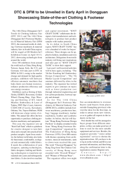


© Copyright 2026