
Appendix F. Guidance for Retrofitting Seattle Streets to Create Dedicated Bicycle Facilities
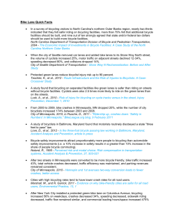
Appendix F.
Guidance for Retrofitting Seattle Streets to Create Dedicated Bicycle
Facilities
The Master Plan recommends a variety of facilities including off-road trails, on-road
facilities for low-volume and low-speed neighborhood streets, and on-road facilities for
higher-volume and higher-speed streets (Seattle’s arterial streets). This guidance
addresses the third category, Seattle’s arterial streets1.
The Master Plan recommends preliminary cross sections for more than 250 miles of arterial
roadway segments in the Bicycle Facility Network through a planning-level analysis of
Seattle roadways. Detailed descriptions of the bicycle facility types used in these cross
sections are in Appendix E. The Master Plan proposes minimum-width configurations that
may be permissible depending on roadway characteristics. It may not be appropriate or
desirable to implement minimum width cross sections in all situations. Engineering
judgment will be required to assess the final design of each roadway cross section.
Implementing some of these facilities will require a change to the existing roadway
configuration.
This guidance is provided as a tool to help the designer accomplish the following tasks:
•
•
•
•
Review the recommended cross section set forth in the Bicycle Master Plan.
Optimize the final proposed cross section dimensions.
Develop an optimum cross section for roadway segments not included within the
Bicycle Master Plan.
Obtain the necessary city, state, and federal approvals for the design (as
appropriate).
Bicycle Facility Decision-Making Process
Table F-1 illustrates the decision-making process that a designer should follow to develop
the most suitable bicycle facility recommendation for any arterial roadway in Seattle. This
table focuses on selecting the most suitable cross section for providing bicycle access,
given specific roadway and traffic characteristics. Intersection considerations are
discussed later in this guidance, but are not included in the table. Below is a description of
the decision-making process shown in Table F-1.
Target Bicycle Facility Type
These guidelines provide key design considerations for a wide variety of Seattle's arterial
street cross sections, in order to identify potential solutions that serve a wide variety of
users (both motorized and non-motorized) in the most efficient way possible. For most
arterial roadways where on-road bicycle facilities are proposed, the target bicycle facility
type is the bicycle lane. A bicycle facility recommendation has been developed for more
than 250 miles of arterial roadways in Seattle through the Master Plan process.
Analysis
There are two main steps in the analysis phase. First, analyze the physical space of the
roadway cross section and assess the generic traffic characteristics (ADT, parking
utilization, sidewalk presence, etc). The designer should consider which elements of the
existing roadway could potentially be modified to provide space for the target bicycle
facility. The following questions should be asked:
1
Non-arterial streets are not included here, but complete streets principles apply to non-arterial streets, as
well. As discussed in other sections of the plan, the city will develop signed bicycle routes and bicycle
boulevards, and is open to other creative ideas for non-arterial streets in the future.
Seattle Bicycle Master Plan - 100 -
Appendix F
•
•
•
•
Can any existing lanes be narrowed?
Can any existing lanes be removed (consider travel lanes, center-turn lanes, and
parking lanes)?
Can the existing pavement be widened, or can the curbs be moved?
Can medians or planting strips (buffers) be narrowed?
Second, the designer should consider the effect changes in the existing cross section will
have on the following operational or environmental factors:
•
•
•
•
•
•
•
•
•
Pedestrian needs (buffers and sidewalk widths).
Roadway capacity.
Traffic volume and speed.
Roadway grade.
On-street parking demand.
On-street parking turnover.
Heavy vehicle traffic (trucks and buses).
Horizontal alignment (curved roadway sections).
Physical space (i.e. constrained by a steep grade, structure, or waterway).
Analysis is critical for selecting the most suitable bicycle facility given the constraints of
each corridor. This phase is discussed in greater detail in the remaining sections of this
appendix.
Alternatives
If analysis finds that the target bicycle facility type is feasible, the project can move
forward to implementation. If there are constraints that would prevent the target facility
from being achieved, alternatives should be developed with the goal of improving bicycle
safety and access to the highest degree possible, given the constraints of the particular
corridor.
The process of developing alternative designs should always be informed by the
recommendations of the Bicycle Master Plan, which identifies a facility type for all
segments of the proposed bicycle network. Other alternatives should be explored as well,
again with the goal of improving bicycle safety and access, and providing the most suitable
bicycle facility given operational and environmental constraints within the corridor. If the
city decides not to proceed with implementing the Bicycle Master Plan recommendation on
a particular roadway, it will document the reason for its decision to choose a different
alternative. The burden is on the city to explain why it is not implementing a
recommendation in the plan.
Selection
Obtain public input on several alternative bicycle facility cross sections. Public input may
make it necessary to conduct additional analysis. Identification of design exceptions
should be made during this phase. If design exceptions are not likely to be approved,
different alternatives should be chosen.
Implementation
Implement the optimal bicycle facility identified through this decision-making process.
Seattle Bicycle Master Plan - 101 -
Appendix F
Table F.1. Summary of Bicycle Facility Decision-Making Process
Seattle Bicycle Master Plan - 102 -
Appendix F
Bicycle Facility Design Guidelines
While the goal of this document is to help engineers and designers develop roadway designs
that meet all of the requirements set forth by city, state, and federal guidance, it is
understood that there is a need to allow flexibility to develop safe and efficient roadway
designs that serve a wide range of users. This need is acknowledged in both the
Washington State Department of Transportation (WSDOT) Design Manual and in the Seattle
Right-of-Way Improvement Manual (ROWIM)2. Both documents provide a detailed
explanation of the required design deviation process3. It is likely that design deviations
will be required to implement some bicycle facilities.
These guidelines are a supplement to local and national bicycle and roadway facility
planning and design standards and guidelines. These guidelines are not a design
standard, and should not be used as such. Application of this guidance requires the use
of engineering judgment when retrofitting Seattle streets to provide bicycle facilities.
When using this guidance, the designer is encouraged to consult the latest versions of the
following documents:
• American Association of State Highway Transportation Officials (AASHTO) Guide for
the Development of Bicycle Facilities, 1999.
• Manual on Uniform Traffic Control Devices, 2003.
• City of Seattle Right-of-way Improvement Manual (ROWIM).
• Washington State, City, and County Design Standards for the Construction of Urban
and Rural Arterials and Collectors.
• A Policy on Geometric Design of Highways and Streets (Green Book), 2004,
AASHTO.
• Standard Plans for Road, Bridge, and Municipal Construction (Standard Plans),
WSDOT, M 21-01.
• Washington State DOT Design Manual, WSDOT, M22-01.
• Washington State DOT Right of Way Manual, WSDOT, M26-01.
Analysis of Roadway and Traffic Characteristics to Determine Bicycle Facilities
The initial part of the analysis process is to identify a theoretical cross section and
determine if that section will fit within the existing roadway width based on operational
and environmental factors. If the existing roadway can not accommodate the desired cross
section, consideration should be given to roadway widening. When considering potential
widening, estimated project costs, and impacts to properties and utilities should be
evaluated.
Careful consideration should also be given to potential impacts to pedestrian facilities.
Reductions in sidewalk width below five feet and reductions or elimination of the buffer
between the road and a sidewalk are not recommended. In locations with higher
pedestrian volumes, sidewalks wider than five feet are needed. In many situations,
roadway widening may be ruled out due to a combination of the above impacts.
Therefore, the remainder of this guideline applies to retrofit projects (i.e., projects that
are constrained by the existing paved, or curb to curb widths).
Analysis is critical for determining the most suitable roadway retrofit design to improve
bicycle accommodation. As shown in Table F-1, the analysis phase in the bicycle facility
decision-making process involves two main steps. First, the designer should consider which
2
3
WSDOT Design Manual, June 2005, Forward; ROWIM, Section 1.1
WSDOT Design Manual, Chapter 330; ROWIM, Section 2.6
Seattle Bicycle Master Plan - 103 -
Appendix F
elements of the existing roadway could potentially be
modified to provide space for bicycle facilities. Second,
the designer should consider operational and
environmental factors that affect the potential to modify
the roadway. The details of these steps are discussed
below.
Roadway Cross Section Elements
While these guidelines focus on strategies that will provide
better bicycle access within the roadway, the needs of
bicyclists must be balanced within the context of the multi-modal needs of Seattle’s
transportation system. Individual roadway cross section elements can either be added,
removed, or the dimensions can change (see Figure F-1, below). These changes must
adhere to roadway engineering guidelines. As previously stated, these guidelines primarily
deal with retrofit projects, therefore cross section elements outside of the existing paved,
or curb to curb width are not addressed.
Figure F-1. Example Roadway Cross Section Elements
Note: roadways without curb and gutter may have swales or ditch drainage.
Travel Lane
Seattle streets are classified as arterials or non-arterials (neighborhood streets). The nonarterials are generally lower volume roadways with pavement widths varying between 20
feet and 40 feet. Centerline striping is not provided on non-arterials and bicycles most
commonly share the travel way with motor vehicles. Bicyclists are allowed to operate
within all travel lanes in Seattle unless expressly prohibited by law (i.e. on I-5).
Seattle Bicycle Master Plan - 104 -
Appendix F
The following discussion relates to roadways classified as arterials.
Design Criteria:
Through traffic lane width - 11 feet
ROWIM4:
Curb lane width - 12 feet
Bus only lane width - 12 feet
Wide outside lane (vehicle/bicycle) width - 14 feet
WSDOT:
AASHTO:
11 feet minimum width; varies based upon speed and road classification
10 feet minimum width; 11-12 feet preferred on higher speed, freeflowing, principal arterials.5
Design Considerations:
AASHTO provides flexibility in the establishment of lane width by discussing the merits of
reduced lane width for interrupted-flow operating conditions and constrained conditions.
In addition, AASHTO states that “local practice and experience regarding lane widths should
also be evaluated.6” The consideration of narrow travel lanes should also take into account
truck and bus volumes.
On constrained roadways where bicycle lanes are not possible, it is preferable to provide as
wide an outside lane as possible to facilitate sharing and to minimize the need for
motorists to cross a centerline or to encroach upon adjacent travel lanes.
Shared Lane Markings within Travel Lanes 7
Shared lane markings (SLM) may be applied within an existing travel lane. They will most
often be utilized in constrained locations where bicycle lanes are not feasible.
Design Criteria:
The shared lane marking shall be as shown in the ROWIM, Figure 4-18. At locations where
parking is allowed adjacent to the travel lane, the center of the marking should be located
a minimum of 11 feet from the curb face or edge of the road.
At locations where parking is not allowed adjacent to the travel lane, the center of the
marking should be located three feet from curb face where there is not a gutter pan, two
feet from the gutter joint where there is a gutter pan, or two feet from the edge of the
pavement where there is not a curb.
Design Considerations:
Shared lane markings may be considered in the following situations:
• On constrained roadways that are too narrow to stripe bicycle lanes.
• To delineate space within a wide outside lane where bicyclists can be expected to
ride.
• On multi-lane roadways where bicyclists can be expected to travel within the
outside lane and motorists should be prepared to change lanes to pass bicyclists.
• On roadways where it is important to increase motorist awareness of bicyclists.
• On roadways where bicyclists frequently ride the wrong way.
• On roadways where bicyclists tend to ride too close to parked cars.
4
ROWIM - 4.6.2 Design Criteria
AASHTO Green Book, 2004, pg. 472
AASHTO Green Book, 2004, pg. 473
7
For further discussion on the shared lane marking treatment, read the Shared Lane Marking Memorandum dated
June 1, 2007. This memorandum is part of the Compendium of Supporting Materials available from the city.
5
6
Seattle Bicycle Master Plan - 105 -
Appendix F
More detailed information about shared lane markings is provided in the Shared Lane
Marking Memorandum, which is part of the Compendium of Supporting Materials available
from the city.
Experimentation:
Because the shared lane marking has not been incorporated into the MUTCD, the city will
consider testing several applications of the marking. These studies should measure before
and after behavior of motorists and bicyclists in conjunction with marking placement and
possible supplemental signs. The intended outcome of these tests is the development of
specific protocols for the use of shared lane markings under the following potential
conditions:
•
•
•
•
•
•
•
•
•
•
Lateral placement of the marking in travel lanes of various widths where there is
no parking.
Lateral placement of the marking in travel lanes of various widths adjacent to
parking.
Placement of shared lane marking beneath parked cars on roadways where the
parking lane becomes a peak hour travel lane designated for shared use with
bicyclists.
Utilize the shared lane marking to indicate the transition between bicycle lanes
and shared lanes.
Appropriate motor vehicle volumes, speeds, lane widths, and number of travel
lanes for using shared lane markings on arterial roadways.
Appropriate motor vehicle volumes, speeds, and lane widths for using shared lane
markings on non-arterial roadways.
Use of shared lane markings on the opposite side of the street as climbing lanes.
Placement of shared lane markings within travel lanes on steep descents or
ascents.
Frequency of shared lane markings in the travel lane (i.e. how often bicyclists and
motorists travel over the markings).
Use of smaller, circular dots with inscribed bicycle symbols in place of shared lane
markings on certain types of roadways.
Bicycle Lane
Bicycle lanes provide exclusive space for bicyclist to
operate within the roadway.
Design Criteria:
Curb or adjacent to parking:
ROWIM: 5 feet, minimum width
WSDOT :
5 feet, minimum width
AASHTO:
5 feet, minimum width
No curb or parking:
ROWIM: 4 feet, minimum width
WSDOT :
4 feet, minimum width
AASHTO:
4 feet, minimum width
Buffered Bicycle Lane
Design Considerations:
The minimum width for a bicycle lane adjacent to a parking lane is five feet. A bicycle lane
adjacent to the edge of the road without a curb may be four-feet wide. A six-inch-wide
solid white line is recommended for designated bicycle lanes. In locations with on-street
parking, two stripes should be used to define a bicycle lane: one six-inch stripe between
the travel lane and the bicycle lane, and one four-inch stripe between the bicycle lane and
Seattle Bicycle Master Plan - 106 -
Appendix F
the parking lane. These stripes should be dashed in areas where motorists can be expected
to merge across the bicycle lane. The design of bicycle lanes wider than six feet should be
used with caution, as they can appear to be vehicular travel lanes to motorists.
A buffered bicycle lane can encourage bicyclists to ride away from the opening doors of
parked vehicles by adding pavement markings to the bicycle lane. This treatment could be
particularly useful to delineate the “dooring area” where:
• Bicycle lanes are adjacent to a seven- or eight-foot-wide on-street parking area.
• Bicycle lanes are adjacent to high-turnover parking.
• There are a high number of dooring complaints or crashes in a particular location.
Buffered bicycle lanes may also be considered on steep roadways where higher bicycle
speeds can be expected and where more severe dooring crashes can be expected. Bicycle
lanes may be accompanied by signs reminding drivers to “look for bikes”8 when opening
their doors.
Center Turn Lane
Center turn lanes remove turning vehicles from through travel lanes. This can improve
roadway capacity and potentially allow for fewer through travel lanes.
Design Criteria:
AASHTO:
10 to 16 feet9
Design Considerations:
The width of the center turn lane should be based upon traffic volume. Careful
consideration should also be given to the determination of whether a continuous center
turn lane is more advantageous than a dedicated left turn lane. For roadways where
turning movements can be restricted to a few locations, it may be more beneficial to
provide medians or crossing islands and dedicated left turn
pockets. AASHTO recommends continuous two-way left turn lanes
be a minimum width of 11-feet.
Dedicated Turn Lane
Similar to center turn lanes, dedicated turn lanes remove turning
vehicles from through travel lanes to improve roadway capacity
and safety, and potentially allow for fewer through travel lanes.
Design Criteria:
ROWIM:
12 feet
WSDOT:
11 feet minimum width; varies based upon speed
and road classification
AASHTO:
9 feet minimum width (arterial design speed less
than 40 mph)10
Design Considerations:
The width of the turn lane should be based upon traffic volume and speed. Careful
consideration should also be given to the determination of the length of the turn lane as it
is often necessary to drop bicycle lanes or narrow travel lanes to install a dedicated turn
lane. Where bicycle lanes are dropped to provide a dedicated turn lane, they should be
dropped prior to the turn lane. Where bicycle lanes are present at a dedicated turn lane,
8
Sign based on transportation alternatives design for warning patrons of taxi cabs to look before
opening their car door - http://www.transalt.org/cabs/
9
AASHTO Green Book, 2004, pg 338
10
AASHTO Green Book, 2004, pg 478
Seattle Bicycle Master Plan - 107 -
Appendix F
they shall be located to the left of right turn lanes and to the right of left turn lanes (i.e. a
one way street with a left-side bike lane).
Parking Area
Design Criteria:
ROWIM:
WSDOT:
AASHTO:
8 feet11 minimum width
10 feet on a bus route
8 feet
7 feet minimum width (non-arterial streets primarily
accommodating passenger vehicles)
8 feet minimum width (arterial street)
10 to 12 feet12 (for use as possible through lane)
Design Considerations:
A seven-foot parking area adjacent to bicycle lanes or wide outside lanes in lieu of the
eight-foot minimum may be used where space is constrained. The addition of a bicycle
lane or a wide outside lane alleviates the primary AASHTO concern of sideswiping.
Research13 has found that parked vehicles can be held closer to the curb or edge of the
roadway with the use of a seven-foot striped parking line.
If bus bulbs are installed for in-lane bus stops, they would be installed in the parking area.
Bus bulbs shall not extend into the bicycle lane. Bicycle lanes can still be provided on
these streets as the bus would stop in the bicycle lane at the bus stop allowing the bicyclist
to pass the bus by using the left part of the right-most travel lane. Alternatively, some
bicyclists may choose to stop and wait for the bus.
Some streets in Seattle have a soft surface shoulder located adjacent to the roadway that
allows parking. Soft surface shoulders where parking is allowed that are narrower than 7’
should be widened or parking should be restricted to improve safety along a roadway. If
parking is allowed, an edgeline should be installed to encourage motorists to park off the
roadway. The roadway edgeline stripe is recommended to be a 4-inch-wide solid white
line. The designer should consider the following options in locations where parked vehicles
continue to encroach on the travel way:
• Increase the edgeline (parking line) width to six-inches.
• Provide parking regulation signs notifying drivers to park off the pavement (i.e. “NO
PARKING ON PAVEMENT”).
• Reconstruct the shoulder with curb and gutter to define the parking area.
Shoulders
Shoulders are located adjacent to a number of roadways in Seattle. Shoulder areas provide
an opportunity for improvements to the roadway cross section but can create sub-optimal
conditions for bicyclists in certain situations.
Design Criteria:
ROWIM:
WSDOT:
AASHTO:
5 feet (non arterial14)
8 feet (parking allowed)
varies
11
This would require a ROWIM policy change to allow for 7-foot parking on all bicycle routes.
AASHTO, pg. 478
How Pavement Markings Influence Bicycle and Motor Vehicle Positioning: A Case Study in Cambridge, MA. Ron
Van Houten and Cara Seiderman. TRB January 2005.
14
ROWIM- Section 4.6.2
12
13
Seattle Bicycle Master Plan - 108 -
Appendix F
Design Considerations:
Shoulders that have a poorly-maintained pavement edge are not desirable for bicyclists
operating close to the edge of the roadway (a common practice for bicyclists riding on
roadways with narrow travel lanes).
Elimination or reduction of the shoulder may be considered under the following
circumstances:
• To provide space for an enhanced bicycle facility (wider travel lane or bicycle
lane).
• In locations where there is excess parking capacity.
• In locations where the shoulder is greater than seven-feet wide.
If a shoulder is designated as a bicycle lane, it must be at least four-feet wide.
Factors that should be Considered when Selecting Bicycle Facilities
Many of the factors previously mentioned (e.g., capacity, traffic volume and speed, onstreet parking turnover, heavy truck volumes, etc.) are taken into consideration when
determining an optimal cross section for a retrofit project. The relationship between these
factors and cross section elements is a key step in the analysis process to determine an
optimal cross section. Capacity, speed, volume, heavy vehicles, grades, and parking
directly relate to the need for, and dimension of cross section elements. These factors are
further discussed below to provide guidance to the designer to achieve increased modal
balance within the constrained cross section, and provide the best possible bicycle facility.
Roadway Capacity
Roadway capacity is considered when examining the number and type of vehicular travel
lanes. If a reduction in the number of travel lanes is desired, a traffic analysis should be
performed to determine if that option is feasible.
Traffic Volume and Speed
Roadways with higher vehicular speed and volumes are less comfortable for cyclists, and
are therefore in more need of dedicated bicycle facilities. Excess capacity can also result
in higher traffic speeds. Some roads may benefit from the fewer travel lanes or conversion
of travel lanes to turning lanes. Reducing traffic volume and/or speed can also allow for
the installation of narrower travel lanes and turn lanes.
Heavy Vehicles
Heavy vehicles (trucks and buses) may require additional operating space on roadways.
Additionally, frequent passing of bicyclists by heavy vehicles in a narrow cross section may
create conflicts. The AASHTO Guide cites “if substantial truck traffic is anticipated,
additional lane width may be desirable.”15 The use of travel lanes below 11-feet wide is not
recommended on streets with a high percentage of heavy vehicles. This guidance
recommends a threshold of 10% of the ADT or greater.
Road Grade
Road grade has the largest affect on bicyclist operating speed. On steep ascents, bicyclists
may be slowed to the speeds of pedestrians. On steep descents, bicyclists may exceed
motor vehicle speeds. On hilly streets, the designer can accommodate bicyclists by
utilizing a climbing bicycle lane in the uphill side of the road. On downhill sections,
15
AASHTO Green Book, 2004, Pg 476
Seattle Bicycle Master Plan - 109 -
Appendix F
bicyclists can be directed to share the lane with motorist. This technique can be used on
constrained rights-of-way to reduce the total width required to accommodate bicyclists in
the roadway cross section. Careful consideration should be given to placing bicycle lanes
adjacent to parking on portions of roadways with steep descents (See Bicycle Lane
discussion).
Generally steep is defined as being a roadway segment that is at least 300 feet in length
with a minimum grade of four percent (4%).
On-Street Parking Demand
Providing ample on-street parking is often considered an important need by the general
public, and efforts to reduce or eliminate it can be met with strong opposition. However,
the reduction or elimination of parking should be considered in areas where bicyclists are
constrained to riding too close to parked vehicles or where enhanced bicycle facilities are
desirable. In locations where there is excess parking capacity, consideration should be
given to the following options:
• consolidate parking to one side of road.
• remove parking completely where there is no demand or sufficient off street
capacity.
• remove parking temporarily where there is a need for additional throughput
capacity (i.e. - peak hour bike lane, bus lane, and/or travel lane).
On-Street Parking Turnover
High parking turnover can affect the safety of all roadway users. Bicyclists are vulnerable
roadway users in part because they often ride adjacent to parked vehicles. When riding
within the area of an opening door, the bicyclists is in danger of being struck and injured.
Existing law16 requires a motorist to not open a door into moving traffic; nonetheless, the
designer should consider this potential hazard in the design process. To reduce the
incidence of “dooring” the designer may consider reducing or eliminating parking,
providing a buffered bicycle lane, or adding dooring warning signs (See Bicycle Lane
discussion).
Bicycle Facility Continuity Considerations at Intersections
Continuity of bicycle facilities at intersections takes into consideration the cross section
elements and design factors mentioned above. Intersection treatments may vary
depending on the approaching cross section. Conversely, bicycle treatments at closely
spaced intersections may determine the cross section between nodes. Under ideal
circumstances a standard bicycle lane would be accommodated at the approach to an
intersection. However, with the frequent need for dedicated turn lanes at intersections,
the roadway cross section can become constrained. The following designs offer options for
accommodating bicycles in these constrained locations.
These designs are considered experimental and it is
recommended that Seattle conduct additional
experimental studies before widespread implementation.
Pocket Lane
Pocket lanes are used when there is not sufficient space
to install a bicycle lane at the approach to an
intersection. Pocket lanes provide for a continuous bicycle
facility through an intersection. They can encourage
Pocket Lane Striping, Berkeley, California
16
Washington Code §46.61.620. Opening and closing vehicle doors – “No person shall open the door of a motor
vehicle on the side adjacent to moving traffic unless and until it is reasonably safe to do so and can be done
without interfering with the movement of other traffic, nor shall any person leave a door open on a side of a
vehicle available to moving traffic for a period of time longer than necessary to load or unload passengers.”
Seattle Bicycle Master Plan - 110 -
Appendix F
motorists to drive more slowly, and maintain a consistent traveling path. The striped
pocket lane encourages through bicyclists to stay to the left of right-turning vehicles, and
the lane enables bicyclists to bypass stopped vehicles. Pocket lanes should be a minimum
of three-feet wide and should not be marked as bicycle lanes (e.g., should not include the
bicycle symbol pavement marking). Pocket lanes are not recommended on roadways with
high speeds or high heavy vehicle volumes (10% of ADT or greater).
Shared Bicycle/Right Turn Lane
Shared bicycle/right turn lanes are used when there
is not sufficient space to install a bicycle lane at the
approach to an intersection. The shared
bicycle/right turn lane encourages bicyclists to
remain to the left of right turning traffic by striping a
dashed bicycle lane on the left side of the right turn
lane. This maintains the visual continuity of the
bicycle lane while still allowing adequate shared space for bicycles and turning vehicles.
As an alternative to a dashed bike lane, a shared lane marking may be placed on the left
side of a right turn lane to indicate that this space is shared between through bicyclists and
right-turning vehicles.
Generic Examples of Roadway Cross Sections
The graphics in this section depict common city of Seattle roadway cross sections. The
basic cross sections are identified by a single letter. Variations of these basic cross
sections are identified with a number following the letter. Each cross section includes
additional considerations that should supplement the considerations that have already been
discussed earlier in the document.
Each of the cross sections is uniquely lettered to correspond to a designation on the
Preliminary Cross Section Map (the map is part of the Compendium of Supporting Materials
available from the city). This map provides an initial concept for the cross section of all
roadways in the recommended Bicycle Facility Network. The cross sections shown on the
Preliminary Cross Section Map are not final recommendations; they are a starting point for
considering alternative bicycle facilities on specific roadways.
As previously stated, the cross sections are based on a planning level analysis, which
generally ruled out a widening option. Therefore, the cross sections are geared toward
minimum widths that may be permissible. As projects move toward implementation, the
designer is encouraged to follow the process outlined in these guidelines and to consult the
reference documents. The designer should also consider the example variations (letter
followed by number) when developing cross section alternatives. For example, the
minimum-width recommendation for roadways with two travel lanes, two bicycle lanes,
and two lanes of parking is cross section L. As additional variables such as modified travel
lane requirements or additional road width become available for that cross section,
alternative striping patterns are detailed as permutations L-1, and L-2.
In addition to the design process outlined above, final design will require field confirmation
of the following elements to assure a complete understanding of the existing conditions:
•
•
•
•
•
•
parking.
roadway width.
curb presence and location.
Drainage.
bus stop locations and lengths.
any other situation that may affect the implementation of a desired cross section,
such as pavement condition, reversible or variable traffic patterns, etc.
Seattle Bicycle Master Plan - 111 -
Appendix F
Constrained Cross Sections One Way Streets
A
Bicycle Lane
One Way One Lane with Soft Shoulders – 22’
Additional Considerations:
•
If parking allowed on shoulder – width of
shoulder should equal or exceed seven feet.
B
Shared Lane
One Way Two Lane with Parking – 34’
Additional Considerations:
•
It may be advisable to place the shared lane
marking in the left lane if the predominant
flow of bicycle traffic is in the left lane;
placement of the marking in the left lane
would follow the practice of locating the
center of the marking from the curb face or
pavement edge.
•
For other placement considerations, read the
Shared Lane Marking Memorandum dated June
1, 2007.
C
Bicycle Lane
One Way Two Lane with Parking – 39’
Additional Considerations:
•
It may be advisable to utilize a buffered
bicycle lane in locations with high parking
turnover.
•
On steep descending grades, it may be more
appropriate to utilize a shared travel lane in
place of a bicycle lane.
C-1
Bicycle Lane
One Way Two Lane with Parking – 42’
Additional Considerations:
•
It may be advisable to utilize a buffered
bicycle lane in locations with high parking
turnover.
•
On steep descending grades, it may be more
appropriate to utilize a shared travel lane in
place of a bicycle lane.
Seattle Bicycle Master Plan - 112 -
Appendix F
Constrained Cross Sections One Way Streets (Continued)
C-2
Shared Lane
Three Lane – 40’
Additional Considerations:
•
If parking is allowed except at rush hour –
utilize design C-3 instead.
•
For other placement considerations, read the
Shared Lane Marking Memorandum dated June
1, 2007.
C-3
Off Peak Bicycle Lane
Two Lane with Peak Hour Restrictions – 40’
Additional Considerations:
•
This should only be utilized on roadways where
parking is restricted in the curb parking lane
during rush hour.
•
The frequency of the tee marking is
experimental. It is suggested that the spacing
be no more than every 30 feet, with 15 feet as
minimum spacing.
D
Bicycle Lane
One Way Three Lane with Parking – 49’
Additional Considerations:
•
It may be advisable to utilize a buffered
bicycle lane in locations with high parking
turnover.
•
On steep descending grades, it may be
appropriate to utilize a shared travel lane
in place of a bicycle lane.
D-1
Bicycle Lane
Three Lane with Parking – 54’
Additional Considerations:
•
It may be advisable to utilize a buffered
bicycle lane in locations with high parking
turnover.
•
On steep descending grades, it may be
more appropriate to utilize a shared travel
lane in place of a bicycle lane.
Seattle Bicycle Master Plan - 113 -
Constrained Cross Sections Two Way Streets
Climbing Lane
Two Lane – 25’
Additional Considerations:
•
If parking is allowed on soft shoulder –
width of the soft shoulder should equal or
exceed 7 feet.
•
The bicycle lane should be placed on the
uphill portion of the roadway.
•
For other placement considerations, read
the Shared Lane Marking Memorandum
dated June 1, 2007.
•
Equal dimensioned shared lanes are
preferred over bicycle lanes on flat
sections of roadway (see example H-1).
E
F
Bicycle Lane
Two Lane – 30’
Additional Considerations:
•
If the roadway has no curb and parking is
allowed on a soft shoulder – width of the
soft shoulder should equal or exceed seven
feet.
G
Two Lane with Parking – 32’
Additional Considerations:
•
It may be advisable to utilize a buffered
bicycle lane in locations with high parking
turnover.
•
The bicycle lane adjacent to parking
should be placed on the uphill portion of
the roadway.
•
For other placement considerations, read
the Shared Lane Marking Memorandum
dated June 1, 2007.
•
Equal dimensioned shared lanes are
preferred over bicycle lanes on flat
sections of roadway (see example H-1).
H
Two Lane with Parking – 34’
Additional Considerations:
•
Use of shared lane marking is optional if it
is desired to provide a bicycle facility.
•
For other placement considerations, read
the Shared Lane Marking Memorandum
dated June 1, 2007.
Seattle Bicycle Master Plan - 114 -
This page intentionally left blank.
- 115 -


© Copyright 2026