ABC
docz
Explore
Log in
Create new account
Download
Report
science
physics
optics
25 Gbit/s silicon microring modulator based on
Data Sheet - Eddystone Broadcast Limited
Over 67 GHz bandwidth hybrid silicon electroabsorption modulator
MO-65
ISOLDE_HVmodulator_Cathi_workshop_Barcelona_V3NEW
Low insertion loss Modulator based on a vertically coupled Photonic
Compact 224-Gbit/s Modulator Modules for Digital Coherent Optical
Chris Roeloffzen - 7 Pennies Consulting
AQUAGAMETE Training School: Optical Microscopy & Image Analysis
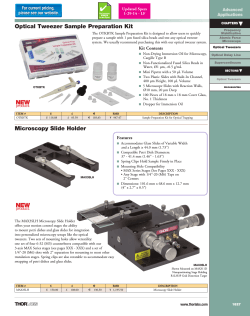
t Optical Tweezer Sample Preparation Kit Advanced Applications
APSACs WESTRIDGE III RAWALPINDI SAMPLE PAPER Subject:
Presentation of Fall 2014 CSE 197 INTERNSHIPS
© Copyright 2026
About abcdocz
DMCA / GDPR
Report