
Digital controlled high power synchronous boost converter
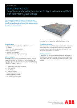
Digital controlled high power synchronous
boost converter based MPPT charge controller
for SPV system
Ch.Venkateswra Rao
PHD scholar, JNTUK, Kakinada
S.S.Tulasiram
Professor, JNTUH, Hyderabad
B.Brahmaiah
Principal, GEC, Guntur
Abstract- Degradation of fossil fuels emphasis to hunt the alternative way of power generation, power electronics
made it possible to extract the power from renewable energy sources effectively and efficiently according to need of
electrical loads. In this research paper, the main focus is, designing of central level (high power) synchronous based
DC-DC converter for the maximum extraction of power from solar PV system at higher DC-DC conversion
efficiency, better performance and stable operation. In this paper proposed system, 1.2kWp.rated synchronous
MPPT charge controller is designed and simulated, with central level configuring in SPV systems at very high
switching frequency, used not only to extract the maximum power from solar array but also for matching the input
solar power characteristics with load characteristics. This closed loop control algorithm, for MPPT based
synchronous converter, designed and implemented in the digital domain, for direct deployment of FPGA controller.
Also presented, small signal analysis of converter, the double lead integral controller design in association with
MPPT algorithm in s-domain, converted to digital domain based on bi-linear transformation, deployed into FPGA.
The Xilinx interfaced MATLAB simulation results demonstrate that, proposed MPPT based synchronous converter
offers maximum power from solar arrays extraction at high efficiency, better dynamic performance in stable region.
Keywords — Synchronous Boost Converter, Digital control, FPGA, MPPT, DC-DC Converter, Constant Voltage
Mode MPPT.
I. INTRODUCTION
With the changing phase, being technologically advanced and economically reputed is a must in the world. It
is a must in order to face the competition and also exists among the top powerful people. On the other hand,
energy crisis is one of the major problems which every country is facing in this era. The developing countries
are least capable of taking a step for the crisis as they are completely dependent on developed countries for their
technological growth. It is fact that the non-renewable resources i.e. fossil fuels have limited reserves, they are
used very roughly by setting the mind for the future and therefore they are depleting at a very fast rate and
existing technology is incapable of controlling its depletion as they are fulfilling our requirements easily. There
are various problems also that occur from the usage of fossil fuels like the cost of fuel in its extraction and
usage, and the harm that they cause to the environment. These are the problems which are forcing the scientific
research scholars to shift their mind set up from nonrenewable energy sources to renewable energy sources.
With the rising energy demands, it is required to utilize the renewable energy resources. It is the right time now,
before time elapses, betters to shifts the world energy scenario from non-conventional to conventional energy
sources. Among the various renewable energy sources, the most useful, efficient, pollution free and very
commonly used is solar energy. It is a leading source of energy which is abundant in nature. But it has not been
properly utilized in a right direction due to technological problems. All professionals in this field have to work
and go beyond the technological advancement so that everyone can utilize the solar energy and full fill the needs
of the world.
A lot of literature has been reported regarding synchronous based dc-dc converters for different types of
applications by researchers. In [1], a new dynamic, non-inverting, synchronous buck-boost converter is designed
for portable applications and validated through experimental results. In [2], authors developed a mixed
synchronous/asynchronous digital control in a FPGA (Field Programmable Gate Array) using VHDL language
to DC-DC boost converter, observed that the controller offers high dynamic performance, frequency modulation
during transients, no quantization effects, and low-complexity. In [3], authors presented a work on the stability
analysis of a non-inverting synchronous buck-boost DC/DC power converter for a solar power management
system under the rapid changes of the atmospheric condition or sunlight incident angle, results of this work
show that the stability margins depend on the inductor and capacitor selected for the converter and depend on
the load conditions also. In [4], a new control method for H-bridge buck-boost converter regulated by single
voltage feedback and dual feed forward controls with synchronous-buck and synchronous-boost operating
modes, to suit the battery powered applications, resulted that the admirable transient performances for the step
load variation without pampering the efficiency for wide range of the supply voltage. In [5], a novel cost
effective and efficient microcontroller based MPPT system for solar photovoltaic system for all fast changing
environmental conditions proposed, offers that high-efficiency, lower-cost, very fast tracking speed and can be
easily modified. In [6], a zero-voltage switching (ZVS) synchronous boost converter is proposed, and states that
to achieve optimum efficiency at a range of load conditions, the magnitude of the resonant current must be
controlled. In [7], robust digital voltage-mode controller design for a synchronous soft-switching boost
converter is presented, the small-signal z-domain transfer functions of several operating modes are formulated
using system identification toolbox of the MATALB, and then used to design controller in digital domain. To
achieve the higher efficiency and reliability with lesser number of components for higher power rating
applications Multiphase interleaved synchronous boost converter became a best choice. In [8], three different
inductor winding designs are presented to optimize the overall efficiency in a multiphase interleaved
bidirectional boost converter. In [9], new control method for Boost converter in discontinuous conduction mode
(DCM) to realize synchronous rectification (SR) of the rectifier and zero voltage switching (ZVS) of the power
switch and proves that optimizing its operating characteristic can improve the ability of whole device. In [10], a
comparative analysis between DMPPT Synchronous Rectification boost converter and Diode Rectification boost
converter is carried out and determined the efficiency performance, thermal behavior and reliability by
numerical and experimental data, based on the analysis demonstrated that the Synchronous Rectification boost
converter is better for the PV system efficiency improvement and thermal requirements. In [11], presented a
FPGA controlled power conditioning system controlled with FPGA for solar PV fed systems. In [12],
implementation of open circuit voltage MPPT controller for solar PV System based on FPGA, mathematical
modeling of solar module and design of DC-DC converter and small signal analysis of charge controller are
presented.
Based on rigorous study of above literature following conclusions can be made:
· FPGA controlled dc-dc converters offers high dynamic performance, frequency modulation during
transients, no quantization effects, and low-complexity [2], [11-12].
· Small signal transfer function of converters is necessary for the proper design of controller for all types
of disturbances and stability analysis [3],[7].
· For all fast changing environmental conditions in solar PV system digital controllers can offer that
high-efficiency, lower-cost, very fast tracking speed and can be easily modified [5].
· Synchronous Rectification boost converter is better for the PV system efficiency improvement and
thermal requirements [8], [9], [10]
None of the aforementioned literature considered FPGA controlled synchronous boost converter based MPPT
charge controller to extract the maximum power from solar PV modules/arrays with better thermal
requirements. Hence, this research study proposes a system to achieve above mentioned properties. Further,
contributions will be extended towards development of transfer function using system identification toolbox of
the MATALB, design controller and converts to digital domain for direct implementation of controller in Xilinx
system generator interfaced MATLAB Simulink environment for the deployment of code into FPGA.
II. PROPOSED PV SYSTEM
The proposed PV system comprises power conditioning unit, not only to extract the maximum power from
solar array but also for matching the input solar power characteristics with load characteristics. The main
elements of PV systems are solar PV array, power conditioning system, energy storing element and the load.
Proposed power conditioning PV system for DC loads is shown in Fig.1.
Fig.1.Block diagram of power conditioning PV system.
A. PV Module:
A solar cell is basically a semiconductor element, which can absorb light energy and converts into electric
energy. Different solar cell combines to form PV module in order to increase the power level. The output in
terms of voltage/ current of a module depends upon the type of combination that is a series or parallel
combination. Combination of several modules in parallel or series, the array can be formed at high power level
[11-13].
The output of solar panel is variable D.C, exhibiting non-linear properties, depends upon its ambience
irradiance and temperature. An increase in the ordinance will increase the open-circuit voltage and short-circuit
current of the solar cell. On the other hand increase of temperature will increases the short-circuit current but
decreases the open-circuit voltage.
Synchronous Boost Converter:
Synchronous boost converter is the modified version of the boost converter, in which the diode used is
replaced by a transistor (MOSFET’S) called second controlled switch. Because of second switch, the cost and
efficiency both are increasing, very high efficiency made compromises with the cost. In standard boost
converter the diode turns on its own after the switch is off, as in addition to this there is a rising voltage across
the diode which results in the power loss. To overcome these losses, a transistor (switch 2) is used in the place
of diode which is synchronized with the switch 1. As PWM deals with the constant frequency and the Ton time is
varied, therefore the power loss is totally dependent on the duty cycle D and thus switching time. In
synchronous boost converter the PWM is applied directly to the switch 1 and with a NOT gate to the switch 2,
called both switches are in synchronized fashion, whenever the switch1 is turned OFF, the switch 2
automatically turns ON, and vice-versa. Hence, fully controlled switches are controlled as per our requirements
to get desired output.
The prime benefit of the synchronous boost converter, is that, it can respond to the fluctuating loads quickly
without any delay, without the switching losses that were previously getting when diodes were used and too
much extent the switching ripples can be minimized. Another advantage of the synchronous boost converter is
that it can be bi-directional, whenever the power in switched from the load end, it can work as synchronous buck
converter and hence this application can be utilized in DC motors. Due to the use of 2 transistors the heating
losses can be also minimized as compared to the diodes and we can also enjoy the different advantages of the
transistors (MOSFET’s) as a comparison to the diodes.
As use of 2 semiconductor transistors offers a wide range of controlling the switching frequency and many
other advantages mentioned above, it has some disadvantages like the cost increases and if both switches are not
synchronized properly it can lead to the failure of the circuit and to reduce the switching time, some extra
circuitry needs to be added which increases the complexity. But beyond all these disadvantages we are
improving the efficiency which is the main motive.
Fig.3.circuit diagram of synchronous based MPPT charge controller
MPPT Techniques: Maximum Power Point Tracking in solar PV, trying to extract the maximum possible power
from the panels at unique operating point. The I-V and P-V characteristics of a PV cell depend upon the solar
radiation intensity and temperature [5]. By varying and controlling the different parameters of the panel like
current, voltage or both, zenith can be reached. The fractional open circuit voltage method is the easiest and
cheapest in implementation point of view and can extract maximum power point with much delay. The
and Voc has a linear relationship which can be given by [8]
= k*Voc
(1)
Where Voc is open circuit voltage,
is the maximum power point voltage. The factor k is usually between
0.71 and 0.78 [7-8], hence the
can be calculated and set as a reference. The output voltage from the DCand the error is used to calculate the
DC synchronous boost converter is measured and compared with
required PWM for switching the MOSFET’s and hence the maximum power can be achieved by equivalent
calculations.
Field Programmable Gate Array
A Field Programmable Gate Array (FPGA) is pre-fabricated device that can be electrically programmed to
become any kind of digital circuit. It is an integrated circuit which is an array of logic cells. It can be made or
designed as requirement of users.
In this paper the proposed system is controlled with the help of FPGA i.e., the CVMPPT method is
programmed in VHDL by using Xilinx space system generator to control the DC-DC boost converter.
SIMULATION RESULTS
To analyze the proposed system, Xilinx interfaced MATLAB Simulink based modeling has been performed
after done proper mathematical design.
In MATLAB solar PV module is modeled with the following specifications as Shown in Table.1.
Table.1 Design specifications of Solar PV Module
Data Sheet Values
Estimated Parameters
Isc (Short circuit current)
7.36A
Iph (Photon current)
Voc (Open circuit voltage)
30.4V
Io(diode current)
7.36
0.104µ
A
Vmpp (Voltage at maximum power)
24.2V
A ( Diode factor)
1.310
Impp (Current at maximum power)
6.83A
Rs (series resistance)
0.251
50
Rsh (Shunt resistance)
1168
Ns (No.of Series connected solar
cells)
Temperature Coefficients
Ki(Temperature Coefficient for 0.057%
Kv (Temperature Coefficient for current)
voltage)
0.346%
By using the above data, PV module is modeled in MATLAB and shown their characteristics; output voltage
and current waveforms are shown in following figure.
Module Voltage
40
35
30
25
0
0.05
0.1
0.15
0.2
0.25
0.3
Time(sec)
Figure9: Solar Module output Voltage
0.35
0.4
Module Current
8
6
4
2
0
0
0.2
0.4
0.6
0.8
1
Time(sec)
Figure10: Solar Module output current
Design specifications of MPPT charge controller:
Input Voltage= 24V, Output Voltage= 60V Output Power = 165W, Switching frequency = 20 KHz
Inductor =700µH, Capacitor C= 470µF and their parasitic elements ESR of inductor = 0.019
capacitor = 0.111 internal on-state resistance of MOSFET= 0.18
-state voltage drop of diode = 0.8V
Step 2. extraction of transfer function from MATLAB Simulink for small signal analysis of charge controller
and to design suitable controller in digital domain
- 5.943e 5 s + 6.021e 8
2
6
Plant transfer function = s + 1264s + 1.247e
Parameterization:
Number of poles: 2 Number of zeros: 1
Number of free coefficients: 4
Use "tfdata", "getpvec", "getcov" for parameters and their uncertainties.
Estimated using TFEST on frequency response data "sysData".
Fit to estimation data: 95.04% (simulation focus)
- 2476s + 2.509e 6
2
6
Plant and modulator transfer function = s + 1264s + 1.247e
- 0.14 s + 174.2
s
Continuous-time controller transfer function =:
P= 0.13996, I= 174.2151, D=0, N=100
Performance and robustness Tr=0.00157, Ts=0.0152, %Mp=17.2, Peak = 1.17. GM = 4.64, PM= 60,
Wpc=1052rad/sec, Wgc=417, Closed loop stable
Bode Diagram
From: e To: u
System: untitled1
Gain Margin (dB): 4.64
A t f requency (rad/s): 1.05e+03
Closed loop stable? Yes
40
20
0
-20
-40
-60
270
225
System: untitled1
Phase Margin (deg): 60
Delay Margin (sec): 0.00251
A t f requency (rad/s): 417
Closed loop stable? Yes
180
135
90
1
10
2
10
3
10
4
10
5
10
Frequency (rad/s)
Step 3. Implementation of designed controller on Xilinx system generator platform and control the power
circuit in Simulink model for the integration of total system.
synchronous charge controller output current
8
6
4
2
0
0
0.02
0.04
0.06
0.08
0.1
0.12
0.14
0.16
0.18
0.2
0.18
0.2
Time(sec)
synchronous charge controller output voltage
250
200
150
100
50
0
0
0.02
0.04
0.06
0.08
0.1
0.12
0.14
0.16
Time(sec)
Input and Output Power of Synchronous charge controller
1500
Input Power(P i)
Output Power(P o)
at illumination level 1
1000
500
at ilumination Level2
0
0
0.02
0.04
0.06
0.08
0.1
0.12
0.14
0.16
0.18
0.2
Time(sec)
III. CONCLUSION
FPGA controlled dc-dc converters offered high dynamic performance, frequency modulation during transients,
no quantization effects, and low-complexity. Small signal transfer function of converters is necessary for the
proper design of controller for all types of disturbances and stability analysis. For all fast changing
environmental conditions in solar PV system digital controllers can offer that high-efficiency, lower-cost, very
fast tracking speed and can be easily modified. Synchronous Rectification boost converter is better for the PV
system efficiency improvement and thermal requirements.
REFERENCES
[1]
[2]
[3]
[4]
[5]
[6]
Sahu, B.; Rincon-Mora, G.A., "A low voltage, dynamic, noninverting, synchronous buck-boost converter for portable applications,"
Power Electronics, IEEE Transactions on , vol.19, no.2, pp.443,452, March 2004
Saggini, S.; Garcea, G.; Ghioni, M.; Mattavelli, P., "Analysis of high-performance synchronous-asynchronous digital control for DCDC boost converters," Applied Power Electronics Conference and Exposition, 2005. APEC 2005. Twentieth Annual IEEE , vol.2, no.,
pp.892,898 Vol. 2, 6-10 March 2005
Jaw-Kuen Shiau; Chun-Jen Cheng; Ching-En Tseng, "Stability analysis of a non-inverting synchronous buck-boost power converter
for a solar power management system," Sustainable Energy Technologies, 2008. ICSET 2008. IEEE International Conference on ,
vol., no., pp.263,268, 24-27 Nov. 2008
Muro, K.; Nabeshima, T.; Sato, T.; Nishijima, K.; Yoshida, S., "H-bridge buck-boost converter with dual feedforward control," Power
Electronics and Drive Systems, 2009. PEDS 2009. International Conference on , vol., no., pp.1002,1007, 2-5 Nov. 2009
Siwakoti, Y.P.; Chhetri, B.B.; Adhikary, B.; Bista, D., "Microcontroller based intelligent DC/DC converter to track Maximum Power
Point for solar photovoltaic module," Innovative Technologies for an Efficient and Reliable Electricity Supply (CITRES), 2010 IEEE
Conference on , vol., no., pp.94,101, 27-29 Sept. 2010
York, B.; Rae-young Kim; Jih-Sheng Lai, "Adaptive frequency control for ZVS synchronous boost converters operated in average
current mode," Applied Power Electronics Conference and Exposition (APEC), 2010 Twenty-Fifth Annual IEEE , vol., no.,
pp.1890,1896, 21-25 Feb. 2010
[7]
Veerachary, M., "Robust digital voltage-mode controller for synchronous soft-switching boost converter," Power Electronics and
Drive Systems (PEDS), 2011 IEEE Ninth International Conference on , vol., no., pp.1131,1136, 5-8 Dec. 2011
[8] Vazquez, A.; Rodriguez, A.; Martin, K.; Arias, M.; Hernando, M.M., "Inductor optimization for multiphase interleaved synchronous
bidirectional Boost converter working in discontinuous conduction mode with zero voltage switching," Energy Conversion Congress
and Exposition (ECCE), 2013 IEEE , vol., no., pp.4977,4984, 15-19 Sept. 2013
[9] Junfei Wang; Feng Zheng; Yu Zhang; Peikang Wang; Xiaoyu Yang; Depeng Bai, "A new control method for boost converter in
discontinuous conduction mode with synchronous rectification and zero voltage switching," ECCE Asia Downunder (ECCE Asia),
2013 IEEE , vol., no., pp.650,654, 3-6 June 2013
[10] Graditi, G.; Adinolfi, G.; Femia, N.; Vitelli, M., "Comparative analysis of Synchronous Rectification Boost and Diode Rectification
Boost converter for DMPPT applications," Industrial Electronics (ISIE), 2011 IEEE International Symposium on , vol., no.,
pp.1000,1005, 27-30 June 2011
[11] Raveendhra, D.; Guruswamy, K.P.; Thakur, P., "FPGA based 2-stage power conditioning system for PV power generation," Power,
Energy and Control (ICPEC), 2013 International Conference on , vol., no., pp.44,50, 6-8 Feb. 2013
[12] Raveendhra, Dogga; Kumar, Babloo; Mishra, Devesh; Mankotia, Meenakshi, "Design of FPGA based open circuit voltage MPPT
charge controller for solar PV system," Circuits, Power and Computing Technologies (ICCPCT), 2013 International Conference on ,
vol., no., pp.523,527, 20-21 March 2013


© Copyright 2026