
Modular Marx Topology for High Boost Ratio DC/DC Boost Converter
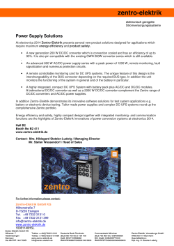
Modular Marx Topology for High Boost Ratio DC/DC Boost Converter Asmarashin Ponniran* Koji Orikawa* Jun-ichi Itoh* *Nagaoka University of Technology 1. Introduction DC/DC converter with high boost ratio is required for some industrial applications, such as for X-ray generation plasma generation and others. In Marx circuits which are usually used for high voltage pulse generator, high conduction losses and copper losses due to large input current are significant problems. In this paper, a new Marx topology DC/DC boost converter with charging choppers is proposed for a high boost ratio. In the proposed circuit, the parallel connection is applied at the input side and the multistage connection is applied at the output side. Therefore, a high efficiency boost converter can be achieved. For the prototype development, only three-stage Marx topology DC/DC boost converter is considered in order to confirm the converter operation and the design method of the input inductors. Fig. 1. Three-stage Marx topology boost converter. Table 1. Stage capacitors operation. 2. Circuit topology In a conventional DC/DC boost converter, the high boost ratio can be achieved by connecting those converters in series or in cascade connection [1]. However, this topology has low efficiency due to the required number of the DC/DC converters. Besides that generally DC/DC converters using high frequency transformers are also can be considered in order to obtain a high boost ratio. However, this kind of converters usually suffers from the bulkiness, large losses and leakage current due to the parasitic capacitance between the transformer windings. On the other hand, switched capacitor DC/DC converters also can achieve a high boost ratio. However, in this topology output voltage stress on the output capacitor is very high due to high output voltage [2,3]. Fig. 1 shows a circuit diagram of a Marx topology boost converter (MTBC) of three-stage. Each stage of the MTBC consists of a conventional boost DC/DC converter, a capacitor and two additional switches. The converter is designed based on a principle of the Marx generator whereby a high-output voltage is generated from a low-voltage DC source [4]. This principle can be realized by charging a number of capacitors in parallel and then suddenly connecting those capacitors in series. Therefore by arranging the combination of capacitors in the proposed converter, a high-output voltage can be generated. By piling stages, the Marx topology boost converter generates high voltage from a low-voltage DC power source. It is noted that 10 to 20 stages might be required in order to reduce input currents stress, switching devices voltage rating and stage capacitor voltages stress in the actual application,. The relationship between the input voltage Vin and the output voltage Vout can be expressed as follows: D Vout = nVin ............................................................... (1) 1− D where D is the duty ratio for the switches S1a, S1b, S2a, S2b, S3a and S3b and n is the number of stage. For the prototype, only three-stage of the Marx topology boost converter is considered. Fig. 2 shows the operation mode of the three-stage Marx topology boost converter. Table 1 and Fig. 2(b) show that the (a) Switching pattern. L3 S3a L3 D3 C3 S3b Lout D3 S3a C3 S3c L2 S2a S2b S2c L1 Vin S1a Cout D2 S2a Vout C2 L1 S1b Vin C1 S3a Mode II Dead-time Td condition S1a, S2a and S3a – ON L3 D3 C3 Lout D3 S3a C3 S3c L2 S2a L2 S2b S2c L1 Vin S1a Cout Lout C2 S2b S2c L1 S1b D2 S2a Vout D1 C1 S3b S3c D2 C2 S1b S1c Mode I S1a, S2a and S3a – ON S1b, S2b and S3b – ON S3b Vout Cout D1 S1a S1c L3 S2b S2c D1 C1 Lout S3c L2 D2 C2 S3b Vin Cout Vout D1 C1 S1a S1c S1b S1c Mode III Additional delay-time Ta condition S1a, S2a and S3a – ON S1c, S2c and S3c – ON Mode IV S1c, S2c and S3c – ON (b) Equivalent circuit. Fig. 2. Operation modes of the three-stage Marx topology boost. stage capacitors C1, C2 and C3 are charged when those capacitors are connected in parallel. Then those stage capacitors are Table 2. Specifications of the experimental prototype circuit. connected in series during discharging condition. Thus from these conditions, the output voltage can be boost-up by advantage of a series connection of the stage capacitors. Therefore a high boost ratio can be achieved. The voltage stresses on the switching devices Sna (S1a, S1b and S1c), Snb (S2a, S2b and S2c) and Snc (S3a, S3b and S3c) are equal to the stage capacitor voltages VC1, VC2 and VC3, respectively. Meanwhile voltages stresses on the D1, D2 and D3 are equal to the VC1, 2VC2, and 3VC3, respectively. In this paper, the inductor current of each stage in the MTBC is designed to be operated in continuous current mode (CCM) in order to minimize the peak input current. Thus the minimum inductor current of each stage should be more than zero to ensure a CCM condition is achieved. The minimum inductance of the input inductor of each stage Lin(m) for CCM operation can be expressed as follows: 2 n (Vin ) D Lin (m ) > ................................................................. (2) 2 Pout f sw where n is the stage, Pout is the output power and fsw is the switching frequency. Meanwhile the inductor current ripple of each stage ∆ILin(m) can be expressed as follows: V D ∆I Lin(m ) = in ................................................................ (3) f swLin(m ) 3. Experimental Results Table 2 shows the specifications of the experimental prototype circuit. The inductance of each stage of the input inductor is designed by using (2). The designed inductance of each stage is 500 µH in this prototype. According to (3), the designed input inductor current ripple on each stage is 2.8 A. Fig. 3 shows the experimental results of the input inductor ripple currents of IL1 and IL2 are 2.8 A, respectively. In Fig. 3, the output power is 500 W and the average input current is 11.1 A. Besides that, the experimental results of the inductor current ripples of the IL1, IL2 and IL3 are according to the designed value though IL3 is not shown in Fig. 3. As a result, both the designed and the experimental results show a good agreement. In addition, in Fig. 3, the experimental results of the inductor currents of IL1 (stage 1) and IL2 (stage 2) are shown. The average inductor currents for the IL1 and IL1 are 3.7 A meanwhile the average inductor current of IL3 (stage 3) is also 3.7 A because the input current is divided by three due to three-stage arrangement in a parallel connection at the input side. Therefore if many stages are considered, the input current will divided by the factor of the stage number and consequently the input current stress, the conduction loss and the copper loss will be reduced. On the other hand, the stage capacitor voltage VC1 is 193 V and the stage capacitor voltages of the VC2 and VC3 show good agreements with the stage capacitor voltage VC1. Besides it is experimentally confirmed that the output voltage of 400 V is achieved. Fig. 4 shows the efficiency of the Marx topology converter. The input and output voltages are fixed at 48 V and 400 V, respectively. The measured maximum efficiency is 92.2 % at the output power of 500 W and 600 W. In addition, the efficiency is increased when the output power is increased. From this characteristic, the conduction loss and copper loss which are increased directly the squared of the current are not dominant in the total power loss when the output power is high. On the other Fig. 3. Experimental waveforms of the output voltage, the capacitor voltage (stage 1), the inductor current (stage 1) and the inductor current (stage 2). 93 92 91 90 89 88 87 86 200 300 400 500 600 Fig. 4. The converter efficiency characteristic. hand, during low output power, the power loss are dominated by the switching loss and the iron loss. As a result, the efficiency is low during low output power. 4. Conclusion This paper presented the high boost ratio of the Marx topology converter whereby the parallel connection at the input side and the multistage connection at the output side are applied. Therefore the high efficiency converter is achieved. The operation of the converter is confirmed by the three-stage Marx topology converter prototype. The achieved maximum efficiency is 92.2 % at the output power of 500 W and 600 W. Reference [1] Denniston, N.; Massoud, A.; Ahmed, S.; Enjeti, P., "Multiple-Module High-Gain High-Voltage DC–DC Transformers for Offshore Wind Energy Systems," Industrial Electronics, IEEE Transactions on , vol.58, no.5, pp.1877,1886, May 2011. (2011). [2] Itoh, J., K. Matsuura and K. Orikawa, "Reduction of a boost inductance using a switched capacitor DC-DC converter". in IEEE 8th International Conference on Power Electronics and ECCE Asia (ICPE & ECCE), 2011. (2011). [3] A. B. Ponniran, K. Matsuura, K. Orikawa, J. Itoh : “Size Reduction of DC-DC Converter using Flying Capacitor Topology with Small Capacitance”, IEEJ Journal of Industry Applications, Vol.3, No.6, pp.446-454 (2014). [4] Veilleux, E.; Ooi, B.-T.; Lehn, P.W., "Marx dc-dc converter for highpower application," Power Electronics, IET, vol.6, no.9, pp.1733,1741, November 2013. (2013).


© Copyright 2026