
Datasheet DALI 0-10V AN - Lunatone Industrielle Elektronik GmbH
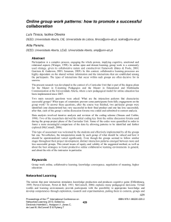
DALI to 0-10V
Interface
Datasheet
DALI to 0-10V Interface
DT5 Converter Module for the
integration of 0-10V dimmer in DALI
lighting systems
Art. Nr. 86458508-AN
© 2015, Lunatone Industrielle Elektronik GmbH
DALI 0-10V AN
DALI 0-10V Interface
Overview
•
•
•
•
•
•
module converting DALI dimming
commands into analogue 0-10V signal
(DALI DT5)
•
the module is especially designed to
operate with drivers with 0-10V
control input
•
transformation of DALI 8-Bit arc
power level into analogue output
signal from 0V to 10V
•
•
selection of linear or logarithmic
dimming curve (DT5)
factory default are the default DT5
settings: output range 1-10V,
logarithmic dimming curve
maximum output current of 1mA
(current sink)
The DALI 0-10V must not be
connected to the mains. It is supplied
directly by the DALI signal line.
The DALI 0-10V has its own address
and can be assigned to DALI groups
and scenes
electrically isolated
Auto Calibration Mode (can be
deactivated or manually triggered via
DALI-Cockpit)
Specification, Characteristics
type
article number
supply
typ. current consumption DALI
input
output
geometry (l/w/h)
weight
permitted ambient temperature
protection class
connecting wire cross section
DALI 0-10V
86458508-AN
via DALI signal line
<4.1 mA
DALI
0.6V-10V analog voltage
100uA-1mA
39.7mm / 28.0mm / 14.2 mm
~10g
0°C-45°C
IP20
connection plan
2
0.5-1.5 mm
geometry
DALI 0-10V AN, Datasheet
© 2015, Lunatone Industrielle Elektronik GmbH
Output Voltage [V]
linear, 1-10V
log, 1-10V
Output range 1-10V:
10
9
8
7
6
5
4
3
2
1
0
control characterisitic:
DALI 0 (=OFF) correlates with a
voltage below and a clear gap
to 1V (<0,8V).
DALI 1-254 is transformed to
1V-10V output voltage
linear
0
50
100
150
200
250
logarithmic
(default setting)
DALI-Value
typical structure
Connection
Function
The interface is supplied directly via the DALI
signal line. It must not be connected to the
mains. The current consumption is typically
below 3mA. For supplying components on a
DALI line the installation of a DALI power
supply (DALI PS) is necessary.
The DALI 0-10V interface converts the desired
DALI dim level in a corresponding output
voltage. Two types of conversion curves are
available (according to DALI DT5). The DALI
direct arc power level [1-254] is linearly or
logarithmic converted to the output signal
[1V-10V]. The relationships are clearly
represented by the control characteristic
diagram. The maximum output current is 1mA
(current sink).
The voltage output supports sinking currents
up to 1mA. The terminals allow cross sections
of the connection wire from 0.5 to 1.5 mm2.
DALI 0-10V AN, Datasheet
© 2015, Lunatone Industrielle Elektronik GmbH
DALI instruction set
The DALI 0-10V module is based on the
standard for DALI control gear (IEC 62386-102)
and device type 5 extension (IEC 62386-206).
With few exceptions the entire instruction set
defined by the DALI standard is supported. For
changing dimming curve DALI commands for
device type 5 are implemented.
Commands and functions referring to the
SYSTEM FAILURE LEVEL are not supported.
This parameter is used as the dim level that
should be applied on the output in case of a
DALI line outage. Since the DALI 0-10V is a bus
powered device there is no possibility to apply
a specific predefined signal on the output
without being under power. In the case of a
DALI-line outage 100% are applied on the
output.
Auto Calibration Mode
http://lunatone.at/en/downloads/Lunatone_
Art24138923_DALI_USB_Datasheet_EN.pdf
DALI PS – power supply for a DALI line
http://lunatone.at/en/downloads/Lunatone_
Art24033444_DALI_PS_Datasheet_EN.pdf
Contact:
Technical Support: [email protected]
Requests: [email protected]
www.lunatone.com
Disclaimer
Subject to change. Information provided without guarantee.
The datasheet refers to the current delivery.
The function in installations with other devices must be tested
for compatibility in advance.
On power up the DALI 0-10V converter is
evaluating if the calibration values for the
output values are still correct or if a
recalibration is required. A calibration will last
up to 2 minutes. The auto calibration routine
can be deactivated and manually triggered via
DALI-Cockpit software tool. During the
calibration the device does not react to any
dimming commands. The DALI Cockpit
provides information if the device is in normal
operation or if the auto calibration is running.
Additional Information and
Equipment
DALI-Cockpit – free configuration tool from
Lunatone for DALI systems
http://lunatone.at/de/dali-systeme/software/
DALI-Manual http://www.daliag.org/c/manual_gb.pdf
DALI USB – PC interface for DALI system. The
DALI-Cockpit can access DALI components
using the DALI USB
DALI 0-10V AN, Datasheet
© 2015, Lunatone Industrielle Elektronik GmbH


© Copyright 2026