
Standards and Guidelines for Municipal Waterworks, Wastewater and Storm Drainage Systems Part 1
Standards and Guidelines for Municipal Waterworks, Wastewater and Storm Drainage Systems Part 1 Standards for Municipal Waterworks of a Total of 5 Parts April 2012 ISBN: 978-0-7785-9633-2 (Printed Edition) ISBN: 978-0-7785-9634-9 (On-Line Edition) Website: http://environment.gov.ab.ca/info/library/8555.pdf © Published by Alberta Queen’s Printer 5th Floor, Park Plaza 10611 - 98 Avenue Edmonton, Alberta T5K 2P7 Tel: 780-427-4952 Fax: 780-452-0668 More information regarding “Part 1 - Standards for Municipal Waterworks" may be obtained by contacting the document owner: Dr. Donald Reid Regional Integration Branch Operations Division Alberta Environment and Sustainable Resource Development 4th floor, Twin Atria 4999-98 Avenue Edmonton, Alberta, T6B 2X3 Additional copies of this and the other Standards and Guidelines for Municipal Waterworks, Wastewater and Storm Drainage Systems publications, the Codes of Practice, and the Environment CDs are available to order on the Alberta Queen’s Printer website at www.qp.alberta.ca or by using the order form as published in this document. Part 1 STANDARDS FOR MUNICIPAL WATERWORKS April 2012 TABLE OF CONTENTS FOREWORD to Part 1 - Standards for Municipal Waterworks (2012)......................................... vi DEFINITIONS / ABBREVIATIONS .............................................................................................. ix 1.0 Waterworks Systems Standards ................................................................................1-1 1.1 Potable Water Quality Standards ...............................................................................1-1 1.2 1.2.1 1.2.1.1 1.2.1.2 1.2.1.3 1.2.1.4 1.2.2 Potable Water Treatment Standards..........................................................................1-1 Surface Water and GWUDI ........................................................................................1-1 Filtration and Disinfection Requirement .....................................................................1-1 Filtration Exemption....................................................................................................1-2 Source Water Monitoring Requirements for Filtered Systems ...................................1-2 Criteria to Determine GWUDI.....................................................................................1-3 Groundwater...............................................................................................................1-3 1.3 1.3.1 1.3.1.1 1.3.1.2 1.3.1.3 1.3.1.4 1.3.2 1.3.2.1 1.3.2.2 1.3.2.3 1.3.2.4 1.3.3 Potable Water Treatment Performance Standards ....................................................1-4 Filtration......................................................................................................................1-4 Rapid Sand Filtration..................................................................................................1-4 Slow Sand Filtration ...................................................................................................1-4 Membrane Filtration ...................................................................................................1-5 Cartridge Filtration......................................................................................................1-5 Disinfection.................................................................................................................1-6 Chlorine (Free and Combined)...................................................................................1-6 Ultraviolet Light...........................................................................................................1-7 Chlorine Dioxide .........................................................................................................1-8 Ozone.........................................................................................................................1-8 Fluoridation.................................................................................................................1-9 1.4 1.4.1 1.4.1.1 1.4.2 1.4.3 Potable Water Treatment Credits...............................................................................1-9 Filtration Credit ...........................................................................................................1-9 System Non-compliance with Respect to Turbidity Reduction.................................1-10 Disinfection Credit ....................................................................................................1-10 Other Options Credit ................................................................................................1-10 1.5 1.5.1 1.5.1.1 1.5.1.2 1.5.1.3 1.5.1.4 1.5.2 1.5.3 1.5.3.1 1.5.3.2 1.5.3.3 Potable Water Treatment Facility Design Standards ...............................................1-11 Surface Water and GWUDI ......................................................................................1-11 Rapid Sand Filtration................................................................................................1-11 Slow Sand Filtration .................................................................................................1-13 Membrane Filtration .................................................................................................1-14 Cartridge Filtration....................................................................................................1-20 Groundwater.............................................................................................................1-21 Disinfection...............................................................................................................1-21 Chlorine / Chloramines.............................................................................................1-21 Ultraviolet Light.........................................................................................................1-29 Chlorine Dioxide .......................................................................................................1-32 - iii - 1.5.3.4 1.5.4 1.5.4.1 1.5.4.2 1.5.4.3 1.5.4.4 1.5.4.5 1.5.4.6 1.5.4.7 1.5.4.8 1.5.4.9 1.5.5 Ozone.......................................................................................................................1-33 Fluoridation...............................................................................................................1-33 General Requirements .............................................................................................1-33 Chemical Feed .........................................................................................................1-34 Metering ...................................................................................................................1-35 Alternate Compounds...............................................................................................1-35 Chemical Storage and Ventilation ............................................................................1-35 Record of Performance Monitoring ..........................................................................1-35 Sampling ..................................................................................................................1-36 Safety .......................................................................................................................1-36 Repair and Maintenance ..........................................................................................1-36 Health and Safety Act...............................................................................................1-37 1.6 1.6.1 1.6.2 1.6.3 Waterworks Systems Operation Standards .............................................................1-37 System Operation Program......................................................................................1-37 Reliability ..................................................................................................................1-37 Operations................................................................................................................1-38 1.7 1.7.1 1.7.2 1.7.2.1 1.7.2.2 Potable Water Treatment Chemical Standards........................................................1-40 Use, Storage and Handling ......................................................................................1-40 Direct and Indirect Additives.....................................................................................1-40 Indirect Additives ......................................................................................................1-40 Direct Additives ........................................................................................................1-40 1.8 1.8.1 1.8.2 1.8.3 1.8.4 1.8.4.1 1.8.4.2 1.8.4.3 Potable Water Treatment Plant Waste–Handling and Disposal Standards .............1-41 Sanitary Wastes .......................................................................................................1-41 Filter Backwash ........................................................................................................1-41 Filter-to-Waste..........................................................................................................1-41 Sludges ....................................................................................................................1-41 Aluminum Sludge .....................................................................................................1-41 Lime Sludge .............................................................................................................1-42 Sludges from Other Coagulants ...............................................................................1-42 1.9 1.9.1 1.9.2 1.9.2.1 1.9.2.2 1.9.3 1.9.3.1 1.9.3.2 1.9.3.3 1.9.3.4 1.9.4 1.9.4.1 1.9.4.2 1.9.4.3 1.9.5 Potable Water Transmission and Distribution Main Standards ................................1-43 Pipe Performance Standards ...................................................................................1-43 Frost Protection for Mains and Reservoirs ...............................................................1-43 Mains........................................................................................................................1-43 Reservoirs ................................................................................................................1-43 Cross-Connection Controls ......................................................................................1-43 Horizontal Separation of Water Mains and Sewers..................................................1-43 Pipe Crossings .........................................................................................................1-44 Valve, Air Relief, Meter and Blow-Off Chambers .....................................................1-44 Backflow Prevention and Control .............................................................................1-44 Disinfection of Mains and Reservoirs .......................................................................1-44 Mains........................................................................................................................1-44 Reservoirs ................................................................................................................1-45 Discharge of Superchlorinated Water ......................................................................1-45 Layout.......................................................................................................................1-45 1.10 1.10.1 1.10.2 1.10.3 Potable Water Quality Performance Monitoring Standards......................................1-45 General.....................................................................................................................1-45 Analytical Requirements...........................................................................................1-46 Compliance Monitoring.............................................................................................1-46 - iv - 1.10.3.1 1.10.3.2 1.10.3.3 1.10.3.4 1.10.3.5 1.10.3.6 1.10.3.7 1.10.4 1.10.4.1 1.10.4.2 1.10.4.3 1.10.4.4 1.10.4.5 1.10.4.6 Bacteriological ..........................................................................................................1-46 Physical Parameters, Organic & Inorganic Chemicals and Pesticides ....................1-47 Turbidity....................................................................................................................1-49 Fluoride ....................................................................................................................1-49 Iron and Manganese ................................................................................................1-50 Trihalomethanes and Bromodichloromethane .........................................................1-50 Disinfection...............................................................................................................1-53 Issue Oriented and Follow-up Monitoring.................................................................1-57 General.....................................................................................................................1-57 Bacteriological ..........................................................................................................1-57 Disinfection...............................................................................................................1-57 Fluoride ....................................................................................................................1-58 Turbidity....................................................................................................................1-58 Organic and Inorganic Chemicals, Pesticides, THM and BDCM .............................1-58 1.11 1.11.1 1.11.1.1 1.11.1.2 1.11.1.3 1.11.2 1.11.2.1 1.11.2.2 1.11.2.3 1.11.2.4 Potable Water Quality Record Keeping and Reporting Standards...........................1-58 Record Keeping........................................................................................................1-58 Five Year Records....................................................................................................1-58 Lifetime Records ......................................................................................................1-59 Sampling and Analysis Records...............................................................................1-60 Reporting Requirements ..........................................................................................1-60 Contravention Reporting ..........................................................................................1-60 Monthly Reporting ....................................................................................................1-61 Annual Reporting......................................................................................................1-62 Electronic Reporting .................................................................................................1-62 1.12 Laboratory Data Quality Assurance Standards ........................................................1-62 1.13 Facility Risk Assessment Standards ........................................................................1-63 1.14 Facility Classification and Operator Certification Standards ....................................1-63 APPENDIX 1-A ...................................................................................................................... 1-A-1 APPENDIX 1-B ...................................................................................................................... 1-B-1 APPENDIX 1-C ......................................................................................................................1-C-1 APPENDIX 1-D ......................................................................................................................1-D-1 APPENDIX 1-E ...................................................................................................................... 1-E-1 Additional Parts published separately are: Part 2 Guidelines for Municipal Waterworks Part 3 Wastewater Systems Standards for Performance and Design Part 4 Wastewater Systems Guidelines for Design, Operating and Monitoring Requirements Part 5 Stormwater Management Guidelines -v- FOREWORD TO PART 1 STANDARDS FOR MUNICIPAL WATERWORKS (2012) Alberta Environment and Sustainable Resource Development (AESRD) is responsible for the Drinking Water and Wastewater Programs for large public systems in Alberta. AESRD considers the establishment of standards and guidelines for municipal waterworks, wastewater and storm drainage facilities an integral part of our regulatory program directed at ensuring public health and environmental protection. AESRD’s objective is to develop comprehensive and scientifically defensible standards and guidelines that are effective, reliable, achievable and economically affordable. Since publication of the last revision of the Standards and Guidelines, Alberta Environment and Sustainable Resource Development has embarked on a process of “decoupling” the various components of the January 2006 document into functionally-associated sections to aid those using the document. This process started with the publication of the January 2006 version of the Standards and Guidelines for Municipal Waterworks, Wastewater and Storm Drainage Systems in the Alberta Gazette. A program of separating the component parts of this document is under way and new parts will eventually replace the corresponding sections in the January 2006 Standards and Guidelines for Municipal Waterworks, Wastewater and Storm Drainage Systems. Until the process of “decoupling” is completed with new “Parts” the existing sections of the 2006 Standards and Guidelines document will remain in operation. This part (Part 1 – Standards for Municipal Waterworks) has all activities and/or system components that directly relate to public health protection; activities. System components that are guidance to best practices are included under “Part 2 – Guidelines for Municipal Waterworks. Alberta Health Services is responsible for the application of the Public Health Act of Alberta. The role of Alberta Health Services, in the spirit of the Public Health Act, applies to all drinking water systems, both large and small, and to all aspects of safe drinking water production and delivery, if there is a concern about health impacts or disease transmission. The system owners / utilities are responsible for meeting AESRD’s regulatory requirements and for the production and delivery of safe drinking water to the consumers. They are also responsible for maintaining water distribution system to the service connection, and will assist the home / building owners to identify any water quality issues within building plumbing. However, home / building owners are still responsible for plumbing repairs, system corrections and water quality within their building. Engineering consultants and / or the system owners / utilities are responsible for the detailed project design and satisfactory construction and operation of the waterworks and wastewater systems. In accordance with the Potable Water Regulation (277/2003) a waterworks system will be designed so that it meets, as a minimum, the performance standards and design requirements set out in the Standards and Guidelines for Municipal Waterworks, Wastewater and Storm Drainage Systems, published by AESRD, as amended or replaced from time to time, or, any other standards and design requirements specified by the Regional Director. AESRD last revised its Standards and Guidelines for Municipal Waterworks, Wastewater and Storm Drainage Systems in January 2006. This present part details all the critical elements of the drinking water program and the associated design and/or performance standards. The key standards are based directly on USEPA’s current surface water treatment rule. They are either narrative criteria or numerical limits for a number of specific parameters, design, construction and operation that ensure a particular environmental quality or public health objective. These are mandatory requirements - vi - with which owners are required to comply. If at any time, the performance standards are compromised, the approval / registration holder shall immediately report to the Regional Director, either: 1. by telephone at 1-800-222-6514; or 2. by a method: a. in compliance with the release reporting provisions in the Act and the regulations, or b. as authorized in writing by the Regional Director. It is recognized that not all existing waterworks systems will meet the standards published in this document. As the new standards will have a direct impact on the safety of drinking water, Alberta Environment and Sustainable Resource Development expects the upgrading to be done in a reasonable period. AESRD will ensure all approved waterworks systems will meet current standards within 5 years of approval renewal, but no later than ten years after the date of this revised Standard. The Director has the ability under Section 4(3) of the Potable Water Regulation to issue a notice to approved or registered waterworks systems identifying specific standards or changes the waterworks system must meet and make and detailing effective dates on which to comply The key changes in this version from the January 2006 Standards are to sections 1.2.2 and 1.13. Alberta Environment and Sustainable Resource Development’s policy on disinfection of groundwater systems set out in Information Letters 1/2011 and 2/2011 [http://environment.alberta.ca/02983.html] is now incorporated into a revised section 1.2.2 in this document. The introduction of the requirement for all municipal waterworks systems to complete and maintain a drinking water safety plan is set out in section 1.13. This is a change of emphasis from the previous risk assessment requirement set out in the January 2006 version. A drinking water safety plan is analogous to a “water safety plan” – a term used by the World Health Organization (WHO). In the 4th edition of the WHO’s Guidelines for Drinking-water Quality 1, WHO state that “the most effective means of securing the safety of a drinking-water supply is through the use of a comprehensive risk assessment and risk management approach that encompasses all steps in the water supply from catchment [watershed] to consumers. The Water Safety Plan approach has been developed to organize and systematize a long history of management practices applied to drinking water and to ensure the applicability of these practices to the management of drinking-water quality. Water safety plans represent an evolution of the concept of sanitary surveys and vulnerability assessments that include and encompass the whole of the water supply system and its operation. The water safety plan approach draw on many of the principles and concepts from other risk management approaches, in particular the multiple-barrier approach and hazard assessment and critical control points (as used in the food and other industries).” AESRD has developed a template and guidance documents to assist in the preparation and maintenance of drinking water safety plans and these can be found at: www.environment.alberta.ca/apps/regulateddwq/dwsp.aspx. A dedicated email address is also 1 http://whqlibdoc.who.int/publications/2011/9789241548151_eng.pdf - vii - available for anyone wishing to enquire further about the drinking water safety plan approach [[email protected]]. All municipal drinking water systems are expected to have completed a drinking water safety plan by December 31, 2013 and to maintain their plan thereafter at a minimum of once per year. - viii - DEFINITIONS / ABBREVIATIONS AO AESRD AWWA BDOC BNR BPJ BPR BPT CBOD CFID DAF DBP DCS DO DWSP DOC EPEA F/M G GCDWQ GWUDI HPC HRT IFID MAC MLSS NH3-N NSF NTU ORP OU PLC QA/QC RBC SAR SBR SRT TBOD TOC TP TSS TTHM UC USEPA UV WHO - Aesthetic Objectives Alberta Environment and Sustainable Resource Development American Water Works Association Biodegradable Dissolved Organic Carbon Biological Nutrient Removal Best Professional Judgement Biological Phosphorus Removal Best Practicable Technology Carbonaceous Biochemical Oxygen Demand at 5 days and 20 oC Continuous feed and intermittent discharge Dissolved Air Flotation Disinfection By-product Distributed Control System Dissolved Oxygen Drinking Water Safety Plan Dissolved Organic Carbon Environmental Protection and Enhancement Act Food to Microorganism ratio Velocity Gradient Guidelines for Canadian Drinking Water Quality Groundwater under the direct influence of surface water Heterotrophic Plate Count Hydraulic Retention Time Intermittent feed and intermittent discharge Maximum Acceptable Concentration Mixed Liquor Suspended Solids Ammonia nitrogen National Sanitation Foundation Nephelometric Turbidity Unit Oxidation Reduction Potential Odour Unit Programmable Logic Controllers Quality Assurance/Quality Control Rotating Biological Contactor Sodium Adsorption Ratio Sequencing Batch Reactor Sludge Retention Time Total Biochemical Oxygen Demand at 5 days and 20 oC Total Organic Carbon Total Phosphorus Total Suspended Solids Total Trihalomethanes Uniformity Coefficient United States Environmental Protection Agency Ultraviolet World Health Organization - ix - Average daily design flow - The product of the following: design population of the facility, and the greatest annual average per capita daily flow which is estimated to occur during the design life of the facility. Co-op - An organization formed by the individual lot owners served by a waterworks system, wastewater system or storm drainage system. Granular filter media: 1. Effective Size (D10) - Size of opening that will just pass 10% of representative sample of the granular filter media. 2. Uniformity Coefficient - A ratio of the size opening that will just pass 60% of the sample divided by the opening that will just pass 10% of the sample. Groundwater - All water under the surface of the ground. Maximum daily design flow (water) - Maximum three consecutive day average of pastrecorded flows, times the design population of the facility. If past records are not available, then 1.8 to 2.0 times the average daily design flow. Maximum hourly design flow (water) - 2.0 to 5.0 times the maximum daily design flow depending on the design population. Owners - Owners of the waterworks systems as defined in the regulations. Peak demand design flow (water) - the maximum daily design flow plus the fire flow. Potable water – As defined in the EPEA. Other domestic purposes in the EPEA definition include water used for personal hygiene, e.g. bathing, showering, washing, etc. Sodium adsorption ratio - A ratio of available sodium, calcium and magnesium in the soil solution which can be used to indicate whether or not the accumulation of sodium in the soil exchange complex will lead to a degradation of soil structure. SAR = Na Ca Mg 1 2 [ + ] / 2 2 Note : All concentrations expressed in milliequivalents per litre Surface water - Water in a watercourse. Watercourse - As defined in the EPEA. -x- 1.0 Waterworks Systems Standards This section outlines all the elements of a drinking water program that shall be adhered to for the safe delivery of drinking water. This includes the standards for the following elements: 1. Water quality; 2. Water treatment and performance; 3. Facility design and operation; 4. Water treatment chemicals; 5. Water treatment plant waste; 6. Water transmission and distribution; 7. Water quality monitoring, record keeping and reporting; 8. Data quality assurance; 9. Facility accreditation; and 10. Facility classification and operator certification. 1.1 Potable Water Quality Standards Potable water in the waterworks system shall meet the health related concentration limits (Maximum Acceptable Concentrations) in the Guidelines for Canadian Drinking Water Quality, published by Health Canada, as amended or replaced from time to time, for the parameters listed in Section 1.10.3 of this document, with the exception noted in Section 1.5.2 (2). The Regional Director at his discretion may establish more stringent limits for the parameters listed, or establish additional parameters not listed in Section 1.10.3. If iron or manganese reduction is practiced, then the treated water concentration for iron and manganese shall be 0.3 mg/L and 0.08 mg/L respectively. 1.2 Potable Water Treatment Standards The level of potable water treatment is dependent on whether the raw water is obtained from a surface supply, groundwater under the direct influence of surface water (GWUDI), or groundwater. Criteria detailed in Section 1.2.1.4, shall be used to determine whether or not a source is under the direct influence of surface water. 1.2.1 Surface Water and GWUDI 1.2.1.1 Filtration and Disinfection Requirement All waterworks systems, with surface water or GWUDI source, shall be provided with filtration and disinfection. Filtration and disinfection together shall achieve a minimum of 3-log reduction of Giardia and Cryptosporidium, and 4-log reduction of viruses. However, based on the raw water cysts and oocysts levels, systems shall achieve higher reduction of Giardia and Cryptosporidium in accordance with the log reduction requirements shown in Table 1.1. New facilities that have not done the source water assessment at the time of application for approval shall achieve a minimum of 3-log reduction of Giardia and Cryptosporidium, and 4-log reduction 1-1 of viruses until the source water assessment is completed. If a system so chooses not to conduct raw water assessment to determine the level of reduction, it shall meet or exceed the maximum 5.5 log reduction of Giardia and Cryptosporidium, and 4-log reduction of viruses. In addition, chlorine residual (free, combined or total chlorine) of not less than 0.1 mg/L shall be maintained in the water distribution system. Table 1.1: Log Reduction Required for Filtered Systems Raw Water Giardia Levels (cysts / 100 L)1 <1 > 1 and < 10 > 10 and < 100 > 100 Raw Water Cryptosporidium Level (oocysts / 100 L)1 < 7.5 > 7.5 and < 100 > 100 and < 300 > 300 Log Reduction 3.0 log 4.0 log 5.0 log 5.5 log 1 For communities with population larger than 10,000, the levels are based on running annual average of monthly samples over a two year period. For communities with population less than 10,000, that are triggered based on E. coli sampling (see Section 1.2.1.3), the levels are based on running annual average of quarterly samples over a two-year period. NOTE: Giardia and Cryptosporidium columns are both used for log reduction determination when granular media depth filtration, or cartridge filtration with >1 micron pore size, is utilized; only the Cryptosporidium column is used for log reduction determination if membrane filtration (<1 micron pore size) is utilized. 1.2.1.2 Filtration Exemption Where a groundwater source is determined to be under the direct influence of surface water (GWUDI) as per Section 1.2.1.4, and where the source water quality conditions are suitable to avoid filtration as determined by the Regional Director, inactivation of Giardia, Cryptosporidium and viruses may be achieved by disinfection only. Disinfection shall achieve a minimum of 3-log reduction of Giardia and Cryptosporidium, and 4-log reduction of viruses. 1.2.1.3 Source Water Monitoring Requirements for Filtered Systems 2 Systems serving a population of at least 10,000 shall sample for cysts and oocysts monthly for a period of two years. Increase the frequency of monitoring to once a week during the spring runoff periods. Systems serving a population of less than 10,000 shall first monitor for E. coli at least every two weeks for a one-year period. For systems that use sources other than lakes or reservoirs, increase the frequency of monitoring to once a week during the spring run-off periods. No cysts and oocysts monitoring will be required under the following conditions: 1. Systems that use lakes or reservoirs as sources and that have an average E. coli concentration of less than 10/100 mL, based on all the samples in a one -year period; or 2. Systems that use sources other than lakes and reservoirs, and that have an average E. coli concentration of less than 50/100 mL, based on all the samples in a one- year period. 2 This applies to surface systems only and not to GWUDI 1-2 Systems meeting the above criteria shall be required to provide filtration and disinfection to achieve a minimum of 3-log reduction of Giardia and Cryptosporidium, and 4-log reduction of viruses. Systems serving a population of less than 10,000, triggered into cysts and oocysts monitoring, will sample at least four times per year for a period of two years, or as determined by the Regional Director based on site specific conditions. Test results below detection limits shall be considered zero in calculating the average value. Cysts and oocysts shall be sampled, analysed and reported in accordance with the USEPA Method 1623, or as amended. 1.2.1.4 Criteria to Determine GWUDI AESRD characterizes groundwaters as one of two types: Groundwater; and Groundwater Under the Direct Influence of Surface Water (GWUDI). A brief description of these two types of groundwater is as follows: 1. Groundwater A raw water supply which is groundwater means water located in aquifer(s) that are either isolated from the surface, or where the subsurface soils act as an effective filter that removes micro-organisms and other particles by straining and antagonistic effect, to a level where the water supply may already be potable but disinfection is required as an additional health risk barrier. 2. GWUDI A raw water supply, which is groundwater under the direct influence of surface water, means ground water having incomplete or undependable subsurface filtration of surface water and infiltrating precipitation. Refer to Appendix 1-E entitled Assessment Guideline for Groundwater Under the Direct Influence of Surface Water (GWUDI) for determining whether a groundwater source is GWUDI. Note that a source determined to be GWUDI would require treatment equivalent to that required by a surface water source. 1.2.2 Groundwater Groundwater systems shall provide disinfection to achieve a minimum of 4-log reduction of viruses 3. A disinfectant residual (total chlorine not less than 0.1 mg/L) shall be maintained in the water distribution system. 3 http://environment.alberta.ca/02983.html 1-3 1.3 Potable Water Treatment Performance Standards 1.3.1 Filtration 1.3.1.1 Rapid Sand Filtration In order to obtain Giardia, Cryptosporidium and virus reduction credits, outlined in Section 1.4.1, conventional and direct filtration systems, as shown in Figure 1.1, shall meet the following turbidity standards. In addition to the turbidity requirement, particle reductions standards may also be used, at the discretion of system owner. Particle counts, however, may be monitored to optimize filtration, either for filter-to-waste times, or for monitoring of spikes, or for low-level optimization down to 0.02 or 0.03 NTU. 1. Turbidity Reduction The treated water turbidity levels from individual filters shall be less than or equal to 0.3 NTU at all times. Exceedance of this limit is allowed up to 1 NTU for a cumulative period of 15 minutes per day per filter for discharge into the clear water tank. The treated water turbidity levels from individual filters shall be based on continuous measurements of the turbidity and recorded at no more than five-minute intervals (with an on-line turbidimeter) at a point upstream of the combined filter effluent line or the clear water tank. 2. Particle Reduction Particle counts (particles greater than 2 µm) from individual filters shall not exceed an absolute value of 50 particles/mL. Exceedance of this limit is allowed up to 200 particles/mL for a cumulative period of 15 minutes per day per filter for discharge into the clear water tank. The particle counts shall be based on continuous measurements of the particles and recorded at no more than five-minute intervals (with an on-line particle counter) at a point upstream of the combined filter effluent line or the clear water tank. 1.3.1.2 Slow Sand Filtration In order to obtain Giardia, Cryptosporidium and virus reduction credits, outlined in Section 1.4.1, slow sand filtration systems shall meet the following turbidity standards: 1. Turbidity Reduction The treated water turbidity levels from individual filters shall be less than or equal to 1 NTU at all times. Exceedance of this limit is allowed up to 3 NTU for a cumulative period of three hours per day per filter for discharge into the clear water tank. The treated water turbidity levels from individual filters shall be based on continuous measurements of the turbidity and recorded at no more than five-minute intervals (with an on-line turbidimeter) at a point upstream of the combined filter effluent line or the clear water tank. 1-4 1.3.1.3 Membrane filtration Cysts / oocysts / virus reduction credit for membrane filtration system shall be based on product specific challenge testing and verified by direct integrity testing of the membrane, as described in the latest edition of the USEPA Membrane Filtration Guidance Manual 4. An independent third party in accordance with the criteria outlined in this guidance manual shall perform the challenge tests. The maximum removal credit shall be the lower of the two values established during the challenge test, or the maximum log removal value verified by the direct integrity test during the course of normal operation. As a minimum standard, the membrane filtration systems shall meet the following turbidity standards, particle reduction standards and direct integrity test standards: 1. Turbidity Reduction The treated water turbidity levels from individual filter train shall be less than or equal to 0.1 NTU at all times. Exceedance of this limit is allowed up to 0.3 NTU for a cumulative period of 15 minutes per day per filter module for discharge into the clear water tank. The treated water turbidity levels from individual filter train shall be based on continuous measurements of the turbidity and recorded at no more than five-minute intervals (with an on-line turbidimeter) at a point upstream of the combined filter effluent line or the clear water tank. 2. Particle Reduction Particle counts (particles greater than 2 µm) from individual filter train shall not exceed an absolute value of 20 particles/mL. Exceedance of this limit is allowed up to 50 particles/mL for a cumulative period of 15 minutes per day per filter train for discharge into the clear water tank. For those membranes that operate under vacuum, where air entrainment may be a problem, exceedance of this limit is allowed up to 200 particles/mL for a cumulative period of 30 minutes per day per filter train. The particle counts shall be based on continuous measurements and recorded at no more than five-minute intervals (with an on-line particle counter) at a point upstream of the combined filter effluent line or the clear water tank. 3. Direct Integrity Test A direct physical test shall be applied daily to each membrane train to identify and isolate integrity breaches. The direct integrity test shall be applied in a manner such that a 2 um hole contributes to the response from the test. The direct integrity test shall be capable of verifying the log reduction value awarded to the membrane process. 1.3.1.4 Cartridge Filtration 5 Cysts / oocysts reduction credit for cartridge filtration system shall be based on product specific challenge testing, as described in the latest edition of the USEPA’s LT2ESWTR Toolbox 4 5 Log reduction credits shall be based on the removal efficiency of the smallest target organism. GWUDI sources only 1-5 Guidance Manual. An independent third party in accordance with the criteria outlined in this guidance manual shall perform the challenge tests. As a minimum standard, the cartridge filtration systems shall meet the following turbidity standards. In addition to the turbidity requirement, particle reductions standards may also be used, at the discretion of system owner. Particle counts, however, may be monitored to optimize filtration, either for filter-to-waste times, or for monitoring of spikes, or for low-level optimization down to 0.02 or 0.03 NTU. 1. Turbidity Reduction The treated water turbidity levels from individual filter module shall be less than or equal to 0.3 NTU at all times. Exceedance of this limit is allowed up to 1 NTU for a cumulative period of 15 minutes per day per filter module for discharge into the clear water tank. The treated water turbidity levels from individual filter module shall be based on continuous measurements of the turbidity and recorded at no more than five-minute intervals (with an on-line turbidimeter) at a point upstream of the combined filter effluent line or the clear water tank. 2. Particle Reduction Particle counts (particles greater than 2 µm) from individual filter module shall not exceed an absolute value of 50 particles/mL. Exceedance of this limit is allowed up to 200 particles/mL for a cumulative period of 15 minutes per day per filter for discharge into the clear water tank. The particle counts shall be based on continuous measurements and recorded at no more than five-minute intervals (with an on-line particle counter) at a point upstream of the combined filter effluent line or the clear water tank. 1.3.2 Disinfection General Performance Requirements All waterworks systems shall provide disinfection to: 1. inactivate the pathogens not removed by clarification and filtration, and achieve the level of cysts / oocysts reduction as stipulated in Table 1.1; 2. inactivate viruses in surface water, GWUDI, and groundwater systems, and achieve the level of virus reduction as stipulated in Sections 1.2.1 and 1.2.2; and 3. maintain total chlorine residual in the water distribution system. 1.3.2.1 Chlorine (Free and Combined) CT Concept Use of the "CT" disinfection concept shall be followed to demonstrate satisfactory treatment since monitoring for very low levels of pathogens in treated water are analytically very difficult. 1-6 The CT concept uses the combination of disinfectant residual concentration (mg/L) and the effective disinfection contact time (in minutes) at maximum hourly flows to measure effective pathogen reduction. The residual is measured at the end of the process, and the contact time used is the T10 of the process unit (time for 10% of the water to pass). Section 1.10.3.7 provides details on how T10 should be determined. CT = Concentration (mg/L) x Time (minutes) Additive CT Values (Disinfection Profiling) Total log reduction by disinfection for a facility can be determined by summing the CTratio achieved in individual process units in series. CTratio is the ratio of CTactual and CTrequired. Different disinfectants can also be used in different process steps. Determine the log reduction for the CT achieved, from the CT Tables in Appendix 1-A and 1-B. Specific Performance Requirements If free chlorine is used as the primary disinfectant, the CT required for the inactivation of cysts shall be in accordance with the CT Tables in Appendix 1-A, and CT required for the inactivation of viruses shall be in accordance with the CT Tables in Appendix 1-B. If combined chlorine is used as the primary disinfectant, the CT required for the inactivation of cysts and viruses shall be in accordance with the CT Tables in Appendix 1-B. If free or combined chlorine is used as the primary disinfectant, the minimum chlorine concentration, at the location where C is measured for the calculation of CT, shall be 0.2 mg/L. If combined chlorine is used as the primary disinfectant, chlorine should be added ahead of ammonia to have sufficient free chlorine to achieve the required removal of viruses. Residual disinfectant concentration in the distribution system, measured as total chlorine, free chlorine, or combined chlorine shall be at least 0.1 mg/L in all of the samples taken. Maximum residual disinfectant concentration, measured as free chlorine shall not exceed 4.0 mg/L, or as combined chlorine shall not exceed 3.0 mg/L, anywhere in the system. 1.3.2.2 Ultraviolet Light UV Dose (based on the IT Concept that is equivalent to the CT Concept of a chemical disinfectant dose) Use of UV Dose (the "IT" disinfection concept) shall be used to demonstrate satisfactory treatment since monitoring for very low levels of pathogens in treated water is analytically very difficult. The degree of inactivation of each target pathogen is based on the UV dose applied to the system. UV dose in ideal reactors is defined as the product of intensity of radiation I 2 (mW/cm ), and the length of time (seconds) the water is exposed to UV radiation. 2 2 UV Dose = IT (mJ/cm ) = Intensity (mW/cm ) x Time (s) For non-ideal field reactors, the delivered dose is validated by empirical methods that involve field reactor performance calibration against an ideal laboratory reactor. 1-7 Specific Performance Requirements If UV light is used as a primary disinfectant, the dose required for the inactivation of cysts, oocysts and viruses shall be in accordance with the IT Tables in Appendix 1-C. If the UV dose is inadequate to achieve the required virus reduction, then UV shall be followed by another disinfectant such as chlorine with the appropriate CT to achieve the desired results with the target virus. UV shall be always followed by a secondary disinfectant such as chlorine to maintain a residual in the water distribution system. 1.3.2.3 Chlorine dioxide CT Concept Same as for chlorine, see Section 1.3.2.1. Specific Performance Requirements If chlorine dioxide is used as the primary disinfectant, the CT required (Concentration C in mg/L x Contact Time T10 in minutes) for the inactivation of cysts and viruses shall be in accordance with the CT Tables in Appendix 1-B. Individual residual oxidants (chlorine dioxide, chlorite and chlorate) shall not exceed the MACs for these substances stipulated in the GCDWQ. Chlorine dioxide shall be followed by a secondary disinfectant such as chlorine to maintain a residual in the water distribution system. 1.3.2.4 Ozone CT Concept As in the case of chlorine and chlorine dioxide, use of the "CT" disinfection concept shall be followed to demonstrate satisfactory treatment since monitoring for very low levels of pathogens in treated water are analytically very difficult. Specific Performance Requirements If ozone is used as the primary disinfectant, the CT required (Concentration C in mg/L x Contact Time T10 in minutes) for the inactivation of cysts and viruses shall be in accordance with the CT Tables in Appendix 1-B. Ozone shall be followed by a secondary disinfectant such as chlorine to maintain a residual in the water distribution system. 1-8 1.3.3 Fluoridation When fluoridation is practised, adequate controls shall be maintained at all times to provide a fluoride ion concentration in treated water to meet the optimum concentration in the latest edition of GCDWQ. A monthly average and daily variation shall be within ± 0.1 mg/L and ± 0.2 mg/L respectively. The Regional Director, under certain circumstances, may allow optimum concentration to be lower than 0.8 mg/L. 1.4 Potable Water Treatment Credits 1.4.1 Filtration Credit If treated water turbidity or particle count meets the prescribed limits in Section 1.3.1, the inactivation credit for Giardia, Cryptosporidium and viruses through filtration shall be determined in accordance with Table 1.2. Table 1.2: Giardia, Cryptosporidium and viruses reduction credit through filtration Technology Conventional filtration Direct filtration Slow sand or diatomaceous earth filtration Microfiltration, ultrafiltration and membrane cartridge filtrationa Nanofiltration and reverse osmosis Microfiltration, ultrafiltration, nanofiltration, reverse osmosis and membrane cartridge filtration, preceded by coagulation, flocculation and sedimentation Cartridge filtrationb a b Cyst/oocyst credit Virus credit 3.0 log 2.5 log 2.0 log 1.0 log 3.0 log 2.0 log Removal efficiency demonstrated through challenge testing and verified by direct integrity testing Removal efficiency demonstrated through challenge testing and verified by direct integrity testing Minimum 3.0 log if removal efficiency demonstrated through challenge testing and verified by direct integrity testing No credit Removal efficiency demonstrated through challenge testing. Maximum 2 log credit given with demonstration of at least 3 log removal efficiency in challenge testing No credit pore size < 1 micron GWUDI only (pore size > 1 micron 1-9 Removal efficiency demonstrated through challenge testing and verified by direct integrity testing Minimum 2.0 log if removal efficiency demonstrated through challenge testing and verified by direct integrity testing 1.4.1.1 System Non-compliance with respect to turbidity reduction For systems not meeting the turbidity or particle requirements outlined in Section 1.3.1, AESRD may grant a limited or no filtration credit for a limited period till the plant can be optimized or upgraded. Plants with no filtration credit shall provide disinfection to achieve at least 3-log reduction of Giardia cysts, 3-log reduction of Cryptosporidium oocysts and 4-log reduction of viruses, or issue boil water advisories to the consumers served by the plants. [Note: Filtration systems that are unable to achieve a finished water turbidity as outlined in Section 1.3.1, will be required to implement a system evaluation program, and develop an optimization or upgrading plan. System evaluation program will include procedures to determine the log reduction requirement of Giardia cysts and Cryptosporidium oocysts]. 1.4.2 Disinfection Credit Depending on the disinfectant used, the inactivation credit for Giardia, Cryptosporidium and viruses through disinfection shall be determined in accordance with the CT Tables in Appendices A or B, or the IT Table in Appendix 1-C. 1.4.3 Other Options Credit Depending on the raw water quality, filtration alone may not be adequate to achieve the inactivation required for cysts and oocysts. Table 1.3 includes the options available to the system owner for further inactivation of cysts and oocysts. The intent of this approach is to provide systems with flexibility in selecting cost effective compliance strategy to achieve the required log reduction. Table 1.3: Giardia, Cryptosporidium and viruses reduction credit through other options (Additional to the credit in Table 1.2) Options Treatment Credit with Design and Implementation Criteria Pre-sedimentation basin with coagulation 0.5 log credit for cysts and oocysts with continuous operation and coagulant addition. Basin shall achieve 0.5 log turbidity reduction based on monthly mean of daily measurements in 11 of the 12 previous months. All flows shall pass through the basins 0.5 log credit for cysts and oocysts for two-stage softening with coagulant addition. Coagulant shall be present in both clarifiers and includes metal salts, polymers, lime, or magnesium precipitation. Both clarifiers shall treat 100% of flow 0.5 log credit for cysts and oocysts if combined filter effluent turbidity is less than 0.15 NTU in 99% of measurements made in a calendar month; or 1.0 log credit for cysts and oocysts if individual filter effluent turbidity is less than 0.1 NTU in 99% of measurements made in a calendar month Log credit for cysts and viruses on demonstration of compliance with CT tables in Appendices 1-A and 1-B Log credit for cysts and viruses on demonstration of compliance with CT tables in Appendix 1-B Two-stage lime softening Combined filter performance; or Individual filter performance Chlorine Chlorine dioxide 1-10 Ozone Log credit for cysts and viruses on demonstration of compliance with CT tables in Appendix 1-B Log credit for cysts, oocysts and viruses on demonstration of compliance with IT tables in Appendix 1-C UV light 1.5 Potable Water Treatment Facility Design Standards 1.5.1 Surface Water and GWUDI This section identifies the design requirements for those technologies acceptable for treatment of surface water and GWUDI. What are included in this section are minimum requirements to ensure reliable and safe drinking water supplies. These design requirements should be considered in conjunction with acceptable design practices and specific design criteria outlined in Part 2 – Guidelines for Municipal Waterworks. 1.5.1.1 Rapid Sand Filtration The rapid sand filtration system shall be designed to produce water that meets the drinking water quality and the minimum performance requirements for rapid sand filtration outlined in section 1.3.1.1. Chemically assisted rapid sand filtration of water is a multi-step treatment process that includes chemical mixing, coagulation, flocculation, solids separation and filtration (conventional treatment); or chemical mixing, coagulation, flocculation and filtration (direct filtration), as illustrated in Figure 1.1. Direct filtration may be used for source water that is consistently low in turbidity, colour and dissolved organic carbon. Water shall be suitable for charge neutralization with low coagulant dosages with the goal of forming a pinpoint sized floc that is filterable, rather than a settleable floc. Direct filtration will be acceptable only if it can be substantiated by undertaking a pilot study using the proposed source water. FIGURE 1.1 TYPICAL WATER TREATMENT PROCESSES FLOCCULATION DIRECT FILTRATION pre-disinfection or oxidation (optional) Figure 1.1 TREATMENT CONVENTIONAL DISINFECTION coagulant or filter-aid chemical addition SOLIDS SEPARATION FLOCCULATION combined flocculationclarification (optional) pre-disinfection or oxidation (optional) FILTRATION coagulant or filter-aid chemical addition 1-11 FILTRATION DISINFECTION The filtration systems shall be designed to produce water that meets the potable water quality standards (section 1.1), potable water treatment standards (Section 1.2), and the potable water treatment performance standards (1.3.1.1). The systems shall meet the following requirements: 1. Chemical Mixing and Coagulation Chemical mixing and coagulation shall be achieved either in a separate process tank or with an in-line mixing device. 2. Flocculation To prevent short-circuiting and to permit defined zones of reduced energy input, the flocculation process shall have two or more stages / compartments unless specifically exempted by AESRD. A minimum of two flocculation trains shall also be provided unless specifically exempted by AESRD. 3. Solids Separation Solids separation shall be achieved either through sedimentation or through flotation. At least two sedimentation basins or two flotation basins shall be provided unless specifically exempted by AESRD. 4. Filtration Filtration represents the final particulate removal step in water treatment. Rapid sand filtration shall be allowed only in conjunction with chemical pre-treatment of water. Any sudden increase or decrease on a dirty filter will cause some detriment to filtered water quality for a brief period, for this reason the filters shall be designed for continuous operation. Filters shall be gravity feed type. Each filter shall be equipped with an on-line turbidimeter with a recorder for continuous monitoring of effluent quality. a. Filtration Rate Filter loading rate shall be considered a key factor in the design of a filtration system from both the filtrate quality and filter-run points of view. The filtration rate is dependent on the quality of raw water, the extent of pre-treatment and the characteristics and depth of the filter media. High-rate filtration (> 9 m/h) will be acceptable only if undertaking a filter column study using the proposed source water can substantiate it. b. Filter to Waste Water treatment plants shall be designed with filter-to-waste provision; piping shall be designed for the capacity of that filter. Precautions should be made to prevent backflow from the filter-to-waste stream to any component of the potable water supply system. The design should provide for switching filter-to-waste flow to filter-on-line (water production) without changing velocity through the filter to reduce turbidity spikes. 1-12 Duration of the filter-to-waste cycle must be tied to the actual turbidity of the wasted water or to a pre-determined time for the turbidity of the wasted water to reach the required limit. c. Number of Filters The number of filter units may vary with the plant capacity. For plants with capacity greater than 150 m3/d, a minimum of two filters shall be provided, each capable of independent operation and backwash. Where possible, three filters or more shall be provided; except during repair/emergency, all filters shall be operational. Where only two filters are provided, each filter should have a hydraulic capacity not less than 150% of design filtration rate. d. Filter Backwash Filter backwash shall be up-flow water wash, or up-flow water wash with surface wash, or up flow water wash with air scour. Declining rate backwash systems are not acceptable. 1.5.1.2 Slow Sand Filtration The slow sand filter system shall be designed to produce water that meets the drinking water quality standards and minimum performance requirements for slow sand filtration outlined in Section 1.3.1.2. 1. Filtration Fluctuating load on the filter upsets the schmutzdecke, resulting in poor quality of filtered water for brief periods. For this reason the filters shall be designed for continuous operation. Each filter shall be equipped with an on-line turbidimeter with a recorder for continuous monitoring of effluent quality. a. Filtration rates Filter loading rate is a key factor in the design of slow sand filtration system from both the filtrate quality and filter run lengths points of view. The percent removal of turbidity generally declines with increasing loading rate. Unless specifically exempt by AESRD, the optimum filtration rates shall be ascertained by pilot testing over the annual cycle. b. Filter to Waste During the filter ripening period, following the start-up of a new filter or a re-built filter bed, filtered water may be of very poor quality. The ripening period typically ranges from about one week to several months. The filters will not meet the minimum performance requirements during the ripening period and the water produced during this period shall be wasted or recycled to the pre-treatment works. Water treatment plants shall be designed with this filter-to-waste provision. Precautions should be made to prevent backflow from the filter-towaste stream to any component of the potable water supply system. 1-13 During the filter-to-waste mode, the filter may be operated at high hydraulic loading rates and wasted water turbidity shall be measured daily until it reaches the acceptable level. c. Number of Filters Slow sand filters shall have a minimum of two or more cells so that when one is out of service for scraping or other reasons, another filter bed can continue producing sufficient amounts of water for the community. Because of the prolonged filter ripening period, systems with two cells shall have each cell capable of producing maximum daily design flow for the community. Systems with more than two cells shall have all cells but one capable of producing maximum daily design flow. 1.5.1.3 Membrane Filtration Membrane filtration shall be a pressure-driven or vacuum-driven process and remove particulate matter larger than 1 micron (µm) using a non-fibrous engineered barrier. The process shall also have a measurable removal efficiency of a target organism that can be verified through the application of a direct integrity test. From municipal drinking water point of view, only Micro Filtration System (MF) and Ultra Filtration System (UF) are of interest. This section outlines the design requirements for MF and UF systems. A Membrane Cartridge Filtration device that utilizes a membrane filtration media capable of removing particulate matter larger than 1 micron, and which can be subjected to direct integrity testing would also satisfy the requirements for membrane filtration. 1. Treatment Objectives It is critical that the treated water quality objectives are defined prior to the membrane process selection. MF and UF membrane systems typically used for surface water treatment or GWUDI can only remove the non-dissolved portion of organic carbon. Dissolved organic removal is typically achieved through pretreatment. Pretreatment chemicals and the organic carbon itself can be contributors to membrane fouling and therefore pretreatment processes should be evaluated carefully. Groundwater containing contaminants such as iron, manganese and arsenic may also be treated with membrane filtration. 2. Design Flow Rate The design flow rate for membrane systems is the net filtered output desired from the membrane system. This shall take into account the loss of feed water used for backwashing and/or rejected from the system (waste stream) and the lost production while a unit or train is out of service for chemical cleaning. 1-14 Recovery Rate is the membrane system’s final product volume over a given time period divided by the feed water flow volume. In order to achieve the lower recovery rate mode, the raw water feed system and waste-handling systems shall be sized to handle the larger flows. The design flow rate per membrane train is a function of the total membrane surface area in the module and the flux rate selected. The membrane surface area per train is a physical characteristic dependant on the membrane manufacturer chosen. The flux rate shall be selected in consultation with the membrane manufacturer and the characteristics of the source water being treated. Optimum flux rates should be selected based on pilot results considering the required design production rates with both cold and warm water. Cold water can significantly reduce the flux rate of a membrane system; hence the seasonal demands should be carefully evaluated. 3. Membrane Selection The style of membrane chosen should best address the feed water conditions, integration with other treatment, hydraulic limitations, residuals, available space and required capacity. Cartridge (pressure) or submerged (vacuum) type systems may be used. Select a membrane manufacturer that adopts and maintains the philosophy of “universal configurations” in order to accommodate future upgrades and products. 4. Piloting The suitability of using a membrane system for a particular raw water source shall be substantiated or verified by conducting a pilot or demonstration study under “worst case” situations. The objective of the pilot or demonstration study is to assess the performance and reliability of the membrane system during the critical raw water conditions. The study shall also determine how the system would operate as an integrated process, react to various levels of pretreatment, and assess the fouling potentials. Sufficient data shall be collected to select the most economical design flux rate, cleaning regime and cleaning frequency for the full-scale system. Prior to conducting a pilot study, a plan shall be developed and submitted to AESRD for review. The plan shall include, but not be limited to the following information: a. Raw water quality data for at least the previous 12-month period highlighting the variations in raw water quality, temperature and seasonal demands. b. Proposed piloting schedule including rationale based on an evaluation of the historical raw water quality and seasonal variations. Critical water quality conditions may include, but not be limited to: high turbidity, cold water, high organics, and the presence of algae. c. A schematic of the proposed pilot set up along with descriptions of the proposed processes and facilities. A comparison should be included of the proposed fullscale facility with any differences noted and discussed. d. A description of the modes of operation to be tested and the parameters to be evaluated. For example: cold and warm temperature flux, percent recovery, trans-membrane pressure, pre-treatment requirements, backwash frequency, backwash duration, backwash method, clean-in-place method and frequency, and post treatment. 1-15 e. Time schedules for each mode of operation. The schedule should address the relationship between the modes of operation and how they relate to the critical water quality conditions. f. Parameters to be monitored, including sampling locations, frequency, and method of monitoring or conducting analytical testing. Feedwater quality parameters are to include, but not be limited to: turbidity, TOC, DOC, UV254 absorbance, algae, calcium, magnesium, iron, manganese, total hardness, total alkalinity, pH and temperature. g. Quality assurance/quality control procedures to be used (including information on the accredited laboratory to be used). h. Description of the analysis to be used for evaluating the data collected. i. A description of proposed challenge tests to substantiate the specific pathogen log removal credit requested by AESRD. j. The proposed plant design capacity ratings as a function of water temperature and other flux rate limitations. k. The pilot study shall be run for a sufficient period to obtain meaningful design data. The selection of the test period(s) shall be based on the historical raw water quality data and critical conditions. The proponent shall prepare the pilot study report documenting the data collected; the analyses performed and summarize the findings and performance recommendations. Recommendations regarding cleaning frequency, integrity testing, maintenance recommendations, anticipated membrane service life and procedures to optimize membrane performance and longevity shall be included. The pilot report shall be submitted to AESRD for review. AESRD, at its discretion, may relax or waive the pilot testing requirements where at least one year of acceptable full scale operational data exists from a water treatment plant which uses membranes similar to what is proposed, treats water of similar quality and under similar operating conditions using the same source. The proponent shall provide an in depth report of this full-scale plant data to AESRD for review. 5. Pretreatment Membrane filtration systems can be successfully integrated into various stages of an existing water treatment facility to replace, enhance or provide additional treatment barriers. The determination of the optimal location for integrating a membrane system within an existing treatment facility depends on site and project specific factors. New or existing pre-treatment systems upstream of the membranes can affect the design of the membrane process. The pre-treatment unit processes that should be evaluated for the integration of membrane filtration systems are as follows: a. Screening Provide pre-screening of any membrane system to protect the membranes from damage by debris. The required screen size is a function of the raw water source and quality and the membrane manufacturer’s requirements. 1-16 b. Oxidation Oxidation can be integrated with membrane processes to assist with organics (TOC & DOC) and taste and odour reduction. It’s recommended that the oxidation process be introduced as far upstream of the membrane process as possible. When using potassium permanganate care should be taken to avoid overdosing. Un-reacted or excess potassium permanganate can affect membrane performance by fouling the membranes or precipitating manganese on the downstream side of the membrane fibres. In addition to AESRD’s overall approval requirements, the proponent shall obtain approval / sign-off for the use of an oxidant from the membrane manufacturer. c. Adsorption Adsorption processes can be integrated with membrane process for removal of organics (TOC and DOC) and taste and odour causing compounds. In addition to AESRD’s overall approval requirements, use of any adsorbent shall be approved by the membrane manufacturer if used upstream of the membrane filters. Where powdered activated carbon (PAC) is proposed, the specific type of PAC should be approved. d. Coagulation Coagulation or enhanced coagulation upstream of the membrane process is typically practiced to precipitate dissolved organic substances (DOC). Pretreatment coagulation is ideally incorporated into a flocculation or clarification process ahead of the membrane process however with some membrane systems the coagulation process can be combined directly into the membrane reactor vessel. In addition to AESRD’s overall approval requirements, the membrane manufacturer shall approve the use of any coagulant. e. Clarification/Sedimentation Clarification or sedimentation upstream of a membrane process is not always necessarily required. However, utilizing one of the two processes to reduce the solids loading on the membranes can improve membrane performance which could in turn lead to less membrane surface area required and extended life of the membranes. AESRD and the membrane manufacturer must approve any upstream processes. 6. Number of Process Trains A minimum of two independent membrane filter trains shall be provided. When determining the number of additional trains, the equipment turndown limitations, instrumentation limits and the range of seasonal flow variations anticipated shall be considered. Ensure that complete trains can be brought on or taken off line as required. When determining the total amount of membrane area and number of membrane trains to meet system demands, the effect of having one train off-line shall be taken into account. When a train is off-line for cleaning the remaining trains will need to be capable 1-17 of operating at a higher flux rate (filtration rate) for the duration of the cleaning cycle in order to meet system demands. For staged plant capacity, the appropriate infrastructure for the projected future demands should be installed. The piping, valves, tankage and pumping units required for the future demands can be either installed initially or, as a minimum, provisions made for the future trains. The purchase of the additional membrane capacity, however, can be deferred until the future demands are approached and be incrementally installed. Installing excess membranes too far in advance is not recommended due to the limited membrane life expectancy of an installed unit, even if this unit is not in service. The contract with the manufacturer shall ensure the availability of compatible membranes at such time as they are required. 7. System Configuration System configuration options will depend on the membrane selected. The general arrangements shall provide safe and convenient access to the membrane modules and ancillary equipment for routine inspection, maintenance and repairs with sufficient clearances and means for membrane removal and replacement. 8. Ancillary Equipment Requirements a. Feed Water or Permeate Pumps & Blowers Where pumps and air blowers are employed, the number of duty pumps and air blowers required will depend on the number of process trains selected and the anticipated range of flows. A standby unit shall be installed and piped accordingly as a common standby unit for any process train in the event one of the duty units is out of service for maintenance or repair. b. Isolation Valves & Unions Isolation valves are required for each individual membrane assembly. The size of the individual modules is such that it is often impractical to isolate individual membrane modules. Instead, isolation valves are to be provided to isolate individual trains [and] membrane assemblies, or subsections of the membrane assemblies c. Piping and Automated Valves Some membrane systems operate over a wide range of pressures and have a significant number of automated valves. Select piping materials, restraints, and actuator speed controls suitable for the intended materials, service and to prevent water hammer. d. Chemical Feed Systems Chemical feed systems shall have standby pumping units. Refer to Section 1.7 “Potable water Treatment Chemicals Standards” for storage and safe handling of the chemicals. 1-18 9. Flow meter Flow meters shall be provided on: 10. a. The main raw water supply line (or individual train raw water supply lines) to measure the feedwater volume entering the membrane system and for flow pacing of any pretreatment chemicals; b. Individual permeate lines from each membrane train to measure the filtration rate and volume of each train and pace post disinfection chemicals; c. Individual reject or concentrate lines from each train to measure the flow rate and volume of waste stream water for calculating the overall recovery rate of the train; d. Individual backwash lines (or use of the permeate flow meters) to measure the backwash flow rate and volume; e. The combined filter effluent line and / or the distribution main header leaving the plant; and f. Dosing of pre-treatment chemicals and determination of system/unit production rate and recovery. On-line meter On-line turbidimeter shall be provided on the common feed water line to the membrane trains. Both on-line turbidimeter and particle counting instruments shall be provided on the permeate discharge from each membrane train. Sample point connections should be provided at each rack or cassette for connection of a portable particle counter to aid in trouble shoot testing in the event of a broken fiber. Provisions shall be made for pH and residual measurement, either online or at convenient sample points, on each membrane CIP tank to monitor the cleaning solution concentrations. Pressure gauges and transmitters are also required on each membrane train to measure transmembrane pressures for monitoring the rate of fouling and backpulse pressures to avoid over pressurization and damage to the membrane fibers. 11. Backwashing and Cleaning Backwashing (back-pulsing) and chemical cleaning frequencies, durations and procedures shall be obtained from the membrane manufacturer, based on pilot study data or similar application data. Provide neutralization of the cleaning solutions either directly in the process tank where the CIP has taken place, or the solutions should be transferred into a holding tank to ensure sufficient time for neutralization and monitoring prior to discharge. 1-19 12. Residuals (Waste) Stream Disposal Alberta Environment and Sustainable Resource Development shall be consulted, as early as possible, when considering the use of membrane technologies, to determine the most suitable options for disposal of waste streams from both pilot scale and full scale membrane plants. 13. Integrity Tests There are five key aspects for achieving an integral membrane system: a. performance requirements (meeting the continuous removal of particles greater than one micron in diameter), b. type of integrity test, c. integrity test criteria and settings (pressures, alarm settings, etc.), d. frequency of integrity testing (daily, weekly, etc.), and e. management of the process and information (data management, shutdown procedures, etc.). There are two basic types of integrity testing: continuous indirect monitoring and periodic direct integrity testing. Indirect integrity monitoring includes online particle counting used as a continuous indication of the membrane integrity. In general, sustained particle counts are expected to remain below 20 cts/mL in the filtrate. If filtrate particle counts jump above 20 cts/mL for an extended period, this may be an indication that a membrane fibre has been breached and shall be isolated and checked for integrity. Direct integrity testing includes such methods as pressure decay, vacuum hold, bubble point, and sonic testing. Direct integrity testing shall be performed at least once daily. In order to receive the requested log removal credits, an integrity-testing program as outlined in the latest edition of the USEPA’s Membrane Filtration Guidance Manual for the proposed plant shall be submitted for approval. 14. Filter-to-Waste Provisions For those systems that have to be tested on-line during production in the event of a membrane integrity breach, filter-to-waste option shall be provided for diversion to waste. 1.5.1.4 Cartridge Filtration Cartridge filters are pressure driven separation processes that remove particles larger than one (1) micron using an engineered porous filtration medium, through either surface or depth filtration. Cartridge filters are allowed under the following conditions: a. As a primary filter System capacity: Source water: Disinfection: < 1.0 L/s GWUDI filtration followed by UV and Chlorine 1-20 b. As a secondary filter Primary filter: Rapid Sand Filtration or Slow Sand Filtration Source water: Surface Disinfection: filtration followed by chlorine The system design and operation of shall be based on the latest edition of the USEPA’s LT2ESWTR Toolbox Guidance Manual. 1.5.2 Groundwater This section provides the design and operational requirements for groundwater systems. 1. Minimum Requirements As a minimum standard, well construction shall conform to the requirements of the Water Well Regulation. All new wells and potentially contaminated wells shall be disinfected in accordance with AWWA standard C654-97, which outlines the procedures for shock chlorination and bacteriological testing for the disinfection of wells supplying potable water. 2. Removal of Fluoride Naturally occurring fluoride up to a concentration of 2.4 mg/L is acceptable in distributed water. Distributed water with concentration greater than 2.4 mg/L shall be treated to reduce the level to 1.5 mg/L or lower, as determined by the Regional Director. 1.5.3 Disinfection 1.5.3.1 Chlorine / Chloramines In the production of chloramines, the ammonia residuals in the finished water, when fed in excess of stoichiometric amount needed, shall be limited to inhibit growth of nitrifying bacteria. 1. On-Site Sodium Hypochlorite Generation Systems As an alternative to chlorine gas or delivered commercial strength sodium hypochlorite, it is permissible to use a weak (0.7 to 0.9%) sodium hypochlorite solution generated onsite. The sodium hypochlorite can either be used for primary or secondary disinfection. The sodium hypochlorite solution is delivered to the treatment process using a system of positive displacement diaphragm metering pumps, peristaltic or centrifugal pumps, eductors or a loop system with metered flow control valves. Redundancy shall be incorporated into the system to ensure that disinfection of the drinking water is not interrupted when any component of the largest unit is out of service. 1-21 a. Generation System Equipment Requirements All generation equipment shall be NSF 61 approved. Sodium hypochlorite generation shall not be permitted outside the sodium hypochlorite room, which is defined as the room where sodium hypochlorite is generated and stored. The water softener and brine tank may or may not be located inside the sodium hypochlorite room. i. Water Softener The number and size of the water softener(s) will depend on the projected range of flows and the hardness of the make-up water. Water hardness used for generating and diluting the brine solution shall be less than 25 mg/L as CaCO3, unless otherwise endorsed by the manufacturer. ii. Water Heater/Chiller A water heater or chiller may be required to adjust the temperature of the water used to make up and dilute the brine solution. The number and size of the water heater(s) or chiller(s) will depend on the anticipated range of flows, and their associated water temperatures. Incoming water shall be maintained between 15C and 27C, or as recommended by the generation system manufacturer. iii. Brine Tanks The brine tank shall be sized to accommodate the maximum day chlorine demand at the maximum flow rate. A standby brine tank shall be provided if the system does not have sufficient sodium hypochlorite storage for a minimum of three days of operation at maximum demand. Brine solution is corrosive, therefore the material used for all associated storage tanks and piping shall be compatible with the solution. The brine solution shall be stored such that the temperature of the solution does not go below 5C. iv. Dosing pumps Where pumps are employed, the number and size of duty pumps required will depend on the chlorine demand and the anticipated range of flows. At least one standby unit shall be installed and piped accordingly as a common standby unit in the event that one of the duty units is out of service. v. Isolation Valves and Unions Sufficient isolation valves and unions shall be provided to allow the removal of any component of the generation equipment for maintenance or repair work without having to take the entire system off line. 1-22 b. Hydrogen Gas Byproduct Safety A minimum of two air blowers shall be provided. When determining the number of additional blowers required, the size and number of generating units and storage tanks shall be considered. At least one standby unit shall be installed and piped accordingly as a common standby unit in the event that one of the duty units is out of service. Blowers shall be required to dilute the hydrogen gas in the generator outlet piping and the headspace of the storage tanks. The blower shall be designed to achieve a hydrogen-in-air concentration of 1% or less, which corresponds to 25% of hydrogen’s lower explosive limit (LEL). The blowers shall vent to outside of the building, and shall be interlocked with the generation process to ensure that sodium hypochlorite is only generated when there is adequate dilution airflow. A minimum of two hydrogen gas detectors shall be placed in each room, for the generation equipment and the storage tanks. The hydrogen gas detectors shall be located at the highest points in each room or immediately over the generating equipment and storage tanks and be set to alarm at 50% of hydrogen’s LEL (2% hydrogen in air) and be interlocked to shut down the generation system. A flow switch and pressure switch shall be located in the dilution air ducting prior to the exterior vent. The flow switch and the pressure indicator shall be intrinsically safe. c. Salt Supply and Storage The salt (sodium chloride) supply shall be NSF 60 approved and also meet any further levels of purity required by the generation equipment manufacturer to ensure no negative impacts on the equipment or the quality of the finished water. Salt shall be stored in a cool dry place where the humidity does not regularly exceed 75%. Salt storage capacity shall be for a minimum 30 days at maximum day chlorine demand, unless exempted by the Regional Director. d. Minimum Generation Capacity The sodium hypochlorite dosing system shall have the capacity to be turned down to meet the minimum day demand, and not exceed the required “free” or “combined” chlorine residual. The entire system shall have the capacity to be able to meet the maximum day chlorine demand at maximum plant flow rate, and maintain the required concentration of “free” or “combined” chlorine residual. The system shall produce a sodium hypochlorite solution that is always below 1% as chlorine. 1-23 e. Sodium Hypochlorite Solution Storage Requirements The sodium hypochlorite solution shall be stored in a location where the ambient temperature is maintained between 5C and 37C. A minimum of one day's chlorine storage is required if there is a 100% redundant generation system, equal to the capacity of the largest generation unit, or else a minimum of two day's storage is required along with the ability to use commercial sodium hypochlorite. The sodium hypochlorite solution shall be stored such that it is not exposed to UV radiation. The material of construction of the storage tank(s) shall be suitable for storing commercial grade NaOCl (10%-16%). All storage tanks shall be fully enclosed and all piping connections and personnel accesses shall be completely sealed from the building interior. Level measurement devices (switches, transmitters etc.) shall be located in all storage tanks and shall be intrinsically safe. f. Sodium Hypochlorite Quality Controls The quality of the sodium hypochlorite shall be such that the required disinfection objectives are met and that it does not negatively impact the quality of the treated water. g. Minimum Generation System Controls and Instrumentation Control of the feed rate shall be: i. automatic / proportional controlled, whereby the sodium hypochlorite feed rate is automatically adjusted in accordance with the flow changes to provide a constant pre-established dosage for all rates of flow; or ii. automatic / residual controlled, whereby a continuous automatic chlorine analyzer determines the residual chlorine level and adjusts the rate of feed accordingly; or iii. compound loop controlled, whereby the feed rate is controlled by a flow proportional signal and residual analyzer signal to maintain a constant residual. All systems shall be designed to have, water and brine flow indicator, cell level sensors, cell temperature sensors, tank level indicator, hydrogen dilution airflow pressure indication and dosing point residual indicator. h. Electrolyzer Cleaning Chemical cleaning frequencies, durations and procedures shall be in accordance with the recommendation made by the on-site generation system manufacturer. Acidic cleaning solutions shall be neutralized prior to discharge. 1-24 i. Containment Secondary containment shall be provided around the generation equipment, storage tanks and metering pumps. The containment shall include structures and valving to enable chemical neutralization prior to discharge. j. Standby Provisions Either a redundant generation system, equal to the capacity of the largest generation unit, or redundant storage to provide a minimum of two days sodium hypochlorite inventory at maximum chlorine demand and maximum plant flow rate, shall be provided. The redundant storage shall allow for bulk commercial sodium hypochlorite storage. A mixing system including flow meters must be installed to enable the commercial sodium hypochlorite to be diluted to a 1% solution for proper dose control. The diluted product will be stored in the same storage tanks as the generated sodium hypochlorite is stored. All the necessary safety and ventilation systems shall be provided if the redundant storage approach is selected. k. Residuals The Regional Director shall determine the method of disposal of water softener regeneration waste, residual acid waste from cell cleaning, and any waste generated from tank cleaning. l. Sodium Hypochlorite Generation Room Design Requirements All rooms in which sodium hypochlorite is being generated shall be designed in accordance with the Alberta Building Code (occupancy, use etc.). If use of commercial sodium hypochlorite is provided in lieu of a redundant generating system, the design shall also comply with commercial sodium hypochlorite storage requirements. i. Equipment Layout Equipment layout will depend on the generation equipment selected and the size of the system. The general arrangements shall provide safe and convenient access to the generator cells, brine tank, softener, storage tank, metering pumps and ancillary equipment for routine inspection, cleaning, maintenance and repairs with sufficient clearances and means for equipment removal and replacement. The brine tanks shall be located such that they facilitate salt delivery and minimize the impacts of salt dust during loading. ii. Ventilation The sodium hypochlorite room ventilation system shall be completely separate from the building ventilation system and be capable of exhausting the air to atmosphere, outside of the building. The air1-25 handling unit shall provide all the make-up air required for the hydrogen gas blowers, and the required ventilation. The quantity of outside air will be directly proportional to the number of dilution blowers operating. Hydrogen dilution air outlets shall be above the roofline. The outlet shall be at least 150 mm above the roof and the point of discharge located to preclude contamination of air inlets to buildings or areas used by people. The vents to the outside shall have insect screens. Air inlets shall be louvered near the ceiling; the air temperature adjusted if required, as not to adversely affecting the sodium hypochlorite generation equipment. iii. Power Supply, Transformer/rectifier, for generation module. The distance between the rectifier and the generation cells must meet the generation system manufacture’s requirements. Conductors and connectors shall be completely enclosed in protective insulation. No opening larger than 6 mm is permitted. iv. Room Access/Egress Room access and egress shall be in accordance with the Alberta Building Code. 2. Chlorination Equipment Requirements For all water treatment facilities, chlorine gas under pressure shall not be permitted outside the chlorine room. Chlorine room is the room where chlorine gas cylinders and/or ton containers are stored. Vacuum regulators shall also be located inside the chlorine room. Chlorine gas flow control and monitoring device may or may not be located inside the chlorine room. For new and upgraded facilities, from the chlorine room, chlorine gas vacuum lines should be run as close to the point of solution application as possible. Injectors should be located to minimize the length of pressurized chlorine solution lines. A gas pressure relief system shall be included in the gas vacuum line between the vacuum regulator(s) and the chlorinator(s) to ensure that pressurized chlorine gas does not enter the gas vacuum lines leaving the chlorine room. The gas pressure relief system shall vent pressurized gas to the atmosphere at a location that is not hazardous to plant personnel; vent line should be run in such a manner that moisture-collecting traps are avoided. The vacuum regulating valve(s) shall have positive shutdown in the event of a break in the downstream vacuum lines. As an alternative to chlorine gas, it is permissible to use sodium or calcium hypochlorite solution with positive displacement pumping. Anti-siphon valves shall be incorporated in the pump heads or in the discharge piping. 1-26 a. Capacity The chlorinator shall have the capacity to dose enough chlorine to overcome the demand and maintain the required concentration of the "free" or "combined" chlorine. b. Methods of Control Chlorine feed system shall be automatic proportional controlled, or automatic residual controlled, or compound loop controlled. Manual chlorine feed system may be installed for groundwater systems with constant flow rate. c. Standby Provision Standby chlorination equipment having the capacity to replace the largest unit shall be provided. For uninterrupted chlorination, gas chlorinators shall be equipped with an automatic changeover system. In addition, spare parts shall be available for all critical equipment. d. Weigh Scales Scales for weighing cylinders shall be provided at all plants using chlorine gas. At large plants, scales of the recording and indicating type are recommended. As a minimum, a platform scale shall be provided. Scales shall be of corrosionresistant material. e. Securing Cylinders All chlorine cylinders shall be securely positioned to safeguard against movement. Tonne containers may not be stacked. f. Chlorine Leak Detection Automatic chlorine leak detection and related alarm equipment shall be installed at all water treatment plants using chlorine gas. Leak detection shall be provided for the chlorine rooms. Chlorine leak detection equipment should be connected to a remote audible and visual alarm system and checked on a regular basis to verify proper operation. Leak detection equipment shall not automatically activate the chlorine room ventilation system in such a manner as to discharge chlorine gas. Chlorine leak detection equipment may not be required for very small chlorine rooms with an exterior door (i.e., floor area less than 3 m2). 1-27 g. Safety Equipment The facility shall be provided with personnel safety equipment to include the following: Respiratory equipment; safety shower, eyewash; gloves; eye protection; protective clothing; cylinder and/or toner repair kits. Respiratory equipment shall be provided which has been approved under the Occupational Health and Safety Act, General Safety Regulation - Selection of Respiratory Protective Equipment. Equipment shall be in close proximity to the access door(s) of the chlorine room. 3. Chlorine Room Design Requirements Where gas chlorination is practiced, the gas cylinders and/or the ton containers up to the vacuum regulators shall be housed in a gas-tight, well illuminated, corrosion resistant and mechanically ventilated enclosure. The chlorinator may or may not be located inside the chlorine room. The chlorine room shall be located at the ground floor level. a. Ventilation Gas chlorine rooms shall have entirely separate exhaust ventilation systems capable of delivering one (1) complete air change per minute during periods of chlorine room occupancy only - there shall be no continuous ventilation. The air outlet from the room shall be 150 mm above the floor and the point of discharge located to preclude contamination of air inlets to buildings or areas used by people. The vents to the outside shall have insect screens. Air inlets should be louvered near the ceiling, the air being of such temperature as to not adversely affect the chlorination equipment. Separate switches for fans and lights shall be outside the room at all entrance or viewing points, and a clear wire-reinforced glass window shall be installed in such a manner as to allow the operator to inspect from the outside of the room. b. Heating Chlorine rooms shall have separate heating systems, if forced air system is used to heat the building. Hot water heating system for the building will negate the need for a separate heating system for the chlorine room. Cylinders or containers shall be protected to ensure that the chlorine maintains its gaseous state when entering the chlorinator. c. Access All access to the chlorine room shall only be from the exterior of the building. Visual inspection of the chlorination equipment from inside may be provided by the installation of glass window(s) in the walls of the chlorine room. Windows should be at least 0.20 m2 in area, and be made of clear wire reinforced glass. There should also be a 'panic bar' on the inside of the chlorine room door for emergency exit. d. Storage of Chlorine Cylinders 1-28 If necessary, a separate storage room may be provided to simply store the chlorine gas cylinders, with no connection to the line. The chlorine cylinder storage room shall have access either to the chlorine room or from the plant exterior, and arranged to prevent the uncontrolled release of spilled gas. Chlorine gas storage room shall have provision for ventilation at thirty air changes per hour. Viewing glass windows and panic button on the inside of door should also be provided. In very large facilities, entry into the chlorine rooms may be through a vestibule from outside. e. Scrubbers For facilities located within residential or densely populated areas, scrubbers shall be provided for the chlorine room. The scrubbers shall be sized to handle leaks at least equal to full release of chlorine from the largest single container in the room. 1.5.3.2 Ultraviolet Light 1. General For UV reactors of nominal diameter 300 mm and smaller, the system design shall follow the standards set out in the most recent of the: - USEPA Ultraviolet Disinfection Guidance Manual; or - German Association on Gas and Water Technical Standard W 294: UV Systems for Disinfection in Drinking Water Supplies – Requirements and Testing; or - NWRI / AWWARF Ultraviolet Disinfection Guidelines for Drinking Water and Water Reuse. For UV reactors greater than nominal diameter 300 mm, the system design shall follow the standards set out in the most recent edition of the USEPA Ultraviolet Disinfection Guidance Manual. For privately owned development consisting of a single building, UV reactors certified under ANSI / NSF 55A may be used to provide the required disinfection. Ultraviolet (UV) light disinfection (using 200-300 nm wavelength) is an acceptable form of treatment for Cryptosporidium, Giardia and bacteria, but it shall be used in conjunction with at least one other disinfectant (free chlorine, chlorine dioxide, or ozone) to provide the specified log reduction of viruses after filtration credits have been considered and a stable distribution system residual (free chlorine, chloramines). A UV dose is applied by passing water through an inline reactor containing low or medium-pressure UV lamps contained within quartz sleeves, and with the lamp, baffle spacing and their configuration designed to meet the required application. The UV dose for a field reactor is a validated calculated dose derived from light intensity (I) readings from online UV sensors that are a function of power level to the lamps and lamp age; 1-29 contact time (T) that is a function of flow rate and flow path through the reactor; the variable germicidal efficiency of different UV wavelengths; the absorption of different wavelengths by the water; and the impact of all of the above on the dose distribution produced by the reactor under the conditions of operation. The resulting dose distribution is the basis of determining the calculated effective UV dose delivered for any particular target organism, and from that dose, the effective logs reduction achieved. This calculated dose must however be validated to be in agreement with the empirically determined UV dose as determined in a bioassay. 2. UV System Location The UV units shall be installed generally following filtration; this will provide some protection against fouling of the UV sleeve, and will utilize the water with the highest transmittance to UV in order to minimize the amount of UV equipment needed to deliver a target dose and also to minimize fluctuations in water quality that would require additional equipment to address the poorest of the water qualities. UV can be installed on a combined filter effluent or following individual filters. Reservoir effluent applications are less desirable because of the inability to monitor and address any "off-specification" water that might occur in the reservoir, and the greater risk of lamp/sleeve breakage at the higher water pressures (or high or low pressures from water hammer). Some UV lamps can run hot, and these units shall not be operated without water in the reactor (for medium pressure lamps, a temperature sensor is required to warn of any increase in temperature within the unit). 3. Validation All UV models shall be validated full-scale (usually by the manufacturer through a third party). Validation is undertaken using acceptable test organisms, and with hydraulics that are defined as standard for such testing. Reactor validation establishes the acceptable operating range of the UV reactor and provides the information for design for specific sites. Daily monitoring confirms that performance continues to be met. UV System Manufacturers shall validate performance using bioassay tests with organisms such as MS-2 bacteriophage or Bacillus subtilis spores for each UV system model. The dose-responses of each test organism should be determined in a collimated beam reactor (an ideal reactor). The bioassay results will be used to define the actual UV dose (Reduction Equivalent Dose or RED for the test organism) that is produced by the reactor being tested under the range of water quality and operating conditions over which the UV system was tested. Systems will need to demonstrate, the actual UV dose (Reduction Equivalent Dose or RED dose for the test organism) that is required to obtain 2 the required RED for a particular target pathogen (e.g. it may require 30-40 mJ/cm RED 2 dose of a resistant test organism for a unit to meet the required 12 mJ/cm RED dose for a less UV-resistant pathogen). The use of test organisms that have a similar or a slightly lesser UV sensitivity compared to the target pathogen will minimize the need for RED correction. Validation of full-scale reactors shall be done on units with essentially the same hydraulic design, baffles and lamp layout as the full-scale installation and similar upstream and downstream piping and valving arrangements. 1-30 To obtain credit for UV disinfection, UV reactors shall be purchased from a supplier with formal third party reactor validation data that covers all the water quality and operating conditions to be encountered, and from which doses and organism inactivation levels can be determined for the relevant target design pathogens (e.g. Giardia & Cryptosporidium, enteric viruses, etc.). The validation certificate and/or report should list the acceptable range of operating conditions for the reactor (Min/Max Flow, UV %T range, lamp power levels, lamp age factor) under which the target design dose and target microbe inactivation levels can be achieved. It should also provide a full explanation of the manufacturers’ dose calculation to obtain the desired inactivation levels. Reactors can use low pressure, low pressure / high out-put, or medium-pressure UV lamps. 4. UV % Transmittance (T) Knowledge of the UV 254 absorbance/transmittance of the water to be treated is critical when designing for good performance of UV systems. Low UVT is usually due to high levels of dissolved organic material (DOC). Waters with UVT above 90% will usually work well with standard UV systems, 80-90% UVT will require more lamps and/or closer spacing, but waters with UVT less than 80% may require more design consideration and require appropriate validation of performance (it is more difficult to design with UVT less than 80%, since the power required to provide the required UV dose rises sharply as the %T decreases). UV Percent Transmittance (UVT) is related to UV Absorbance (A) as per the following equation: UVT = 100 x 10 -A Where the wavelength used is 254 nm, e.g. a UV = 89.1% (1 cm path length). 254 absorption coefficient of 0.050 cm-1 Design of UV systems should ideally be based on the worst-case water transmittance of th at least 12 months of UVT data for each facility (e.g., using the 5 percentile of monthly, bimonthly or weekly samples). If the UVT needs to be improved, then pre-treatment ahead of UV should be considered (enhanced coagulation, PAC or GAC treatment). UVT measurements should be performed on water, as it would enter the reactor (no lab filtration or pH adjustment. 5. Fouling UV installations may also experience problems due to fouling of the lamp sleeves if levels of iron, manganese, hardness, alum, alkalinity or other chemical parameters are above recommended limits. LSI (Langelier Saturation Index) and CCPP (Calcium Carbonate Precipitation Potential) indices should be close to zero. UV units should have on-line mechanical sleeve cleaning devices or provision for physical-chemical cleaning; this will handle most normal levels of possible contaminants. 6. Power Supply UV reactors (medium pressure lamps) are sensitive to fluctuating power supply, and can take 5-10 minutes to restart if power drops off (voltage fluctuations, brown-outs, 1-31 momentary power-outs). Utilities should evaluate the reliability and quality of their power supply (if necessary backup power generators or UPS power supplies can be considered to limit the down – time of the power failure). 7. Chlorine Residual Reduction If chlorine or combined chlorine residuals are present entering the UV reactor, the residual will decrease noticeably in passing the reactor. This effect is magnified if the water is receiving a higher UV dose e.g., due to turndown limits. Any chlorine, chloramines or permanganate residual present will decrease the UVT and such decreases should be incorporated into the design. 8. Broken Lamps/Mercury Spillage Utilities shall develop an emergency response procedure for dealing with broken/cracked lamps/sleeves. The lamps contain a small amount of mercury, typically less than 1 gm per lamp and typically with modern lamp technology around 0.2 mg per watt of electrical power rating of the lamp. Any problems with lamp should be investigated to confirm whether breakage has occurred. The response for dealing with broken / cracked / lamps / sleeves should include notification of AESRD, disposal of reactor water to waste where possible, and ongoing monitoring of water quality for mercury levels. One (1) gm of mercury dispersed in 1 ML of water would result in a 1 μg/L concentration (which is the current Health Canada Guideline MAC), so the risk from one lamp breakage is low. Multiple lamp breakages pose a higher risk. Lamp breakage offline (handling, storage, etc) should be handled with small mercury spill kits. 9. Maintenance Program Utilities should develop a regular maintenance program to calibrate sensors, check lamps, quartz sleeves, lamp cleaning mechanisms, and to carry out UV lamp replacement as per the manufacturer’s recommendation. 10. Contingency Plan Utilities shall have in place a contingency plan for the possibility of total UV system outage. 11. Redundancy The system shall be designed such that with the largest unit out of service, the remaining units shall provide the required disinfection. 1.5.3.3 Chlorine dioxide Chlorine dioxide provides good cysts and virus protection but its use is limited by the restriction on the maximum residual of 0.5 mg/L ClO2/chlorite/chlorate allowed in finished water. This limits usable residuals of chlorine dioxide at the end of a process unit to less than 0.5 mg/L. The effectiveness of chlorine dioxide also decreases with decrease in temperature. 1-32 Where chlorine dioxide is approved for use as an oxidant, the preferred method of generation is to entrain chlorine gas into a packed reaction chamber with a 25% aqueous solution of sodium chlorite (NaClO2). Warning: Dry sodium chlorite is explosive and can cause fires in feed equipment if leaking solutions or spills are allowed to dry out. 1.5.3.4 Ozone Ozone is a very effective disinfectant for cysts, oocysts and viruses. Ozone becomes less effective in cold waters, which limits its application for oocyst inactivation under cold-water conditions. Ozone CT values shall be determined for the ozone basin alone; an accurate T10 value shall be obtained for the contact chamber, residual levels measured through the chamber and average ozone residual calculated. Ozone does not provide a system residual and should be used as a primary disinfectant only in conjunction with free and/or combined chlorine. Ozone does not produce chlorinated by-products (such as trihalomethanes) but it may cause an increase in such by-product formation if it is fed ahead of free chlorine; ozone may also produce its own oxygenated by-products such as aldehydes, ketones or carboxylic acids. Any installed ozonation system shall include adequate ozone leak detection alarm systems, and an ozone offgas destruction system. Ozone may also be used as an oxidant for removal of taste and odour or may be applied as a pre-disinfectant. Ozone production, operation and maintenance of ozonator shall be in accordance with USEPA’s Alternative Disinfectants and Oxidants Guidance Manual – April 1999. 1.5.4 Fluoridation 1.5.4.1 General Requirements In addition to the specific criteria outlined in this Section, all requirements specified under Section 1.7 – Potable Water Treatment Chemicals Standards should also be complied if fluoridation is practiced. Any person proposing to add fluoride to a potable water supply shall apply for and obtain an approval or registration or an amendment to an approval or registration from AESRD. This application shall contain the following information: 1. a copy of the bylaw of the municipal council, which provides the authority to fluoridate; 2. the number of the appropriate approval or registration issued with respect to the existing municipal plant; and 3. an engineering report, including: a. a description of the proposed fluoridation equipment, b. a statement identifying the fluoride compound that is proposed to be added, c. a description of chemical storage and ventilation, d. a description of the water metering used at the water treatment plant, 1-33 e. the generic name of the chemical to be used as the source of fluoride ion, and its fluoride content, f. a current chemical analysis of the fluoride content of the raw water, g. the name and qualifications of the person directly responsible for the operation of the proposed fluoridation process, h. the type of equipment proposed at the water treatment plant to determine the fluoride concentration of the water, and i. the description of the testing procedure to be used to determine the fluoride level of the water. 1.5.4.2 Chemical Feed The equipment used for feeding the fluoride to water shall be accurately calibrated before being placed in operation, and at all times shall be capable of maintaining a dose within 5% of the rate at which the machine is set. The following chemical feed practices apply: 1. Where a dry feeder of the volumetric or gravimetric type is used, a suitable weighing mechanism shall be provided to check the daily amount of chemical feed; 2. Hoppers should be designed to hold a 24-hour supply of the fluoride compound and designed such that the dust hazard to operators is minimized; 3. Vacuum dust filters shall be installed with the hoppers to prevent dust from rising into the room when the hopper is filled; 4. Dissolving chambers are required for use with dry feeders, and the dissolving chambers shall be designed such that at the required rate of feed of the chemical the solution strength will not be greater than 1/4 of that of a saturated solution at the temperature of the dissolving water. The construction material of the dissolving chamber and associated piping shall be compatible with the fluoride solution to be fed; 5. Solution feeders shall be of the positive displacement type and constructed of material compatible with the fluoride solution being fed; 6. The weight of the daily amount of fluoride fed to water shall be accurately determined; 7. Feeders shall be provided with anti-siphon valves on the discharge side. Wherever possible, positive anti-siphon breakers other than valves shall be provided; 8. A "day tank" capable of holding a 24-hour supply of solution shall be provided for systems not equipped with on-line continuous fluoride monitors; 9. All equipment shall be sized such that it will be operated in the 20 to 80 percent range of the scale, and are capable of feeding over the entire pumpage range of the plant; 10. Alarm signals are recommended to detect faulty operation of equipment; and 11. The fluoride solution should be added to the water supply at a point where any treatment processes following the point of addition would not remove the fluoride and where it will be mixed with the water. It is undesirable to inject the fluoride compound or solution directly on-line unless there are provisions for adequate mixing. 1-34 1.5.4.3 Metering Metering of the total water to be fluoridated shall be provided, and the operation of the feeding equipment is to be controlled unless specifically exempted by AESRD. Control of the feed rate shall be: 1. Automatic / proportional controlled, whereby the fluoride feed rate is automatically adjusted in accordance with the flow changes to provide a constant pre-established dosage for all rates of flow; or 2. Automatic / residual controlled, whereby a continuous automatic fluoride analyzer determines the residual fluoride level and adjusts the rate of feed accordingly; or 3. Compound loop controlled, whereby the feed rate is controlled by a flow proportional signal and residual analyzer signal to maintain a constant residual. 1.5.4.4 Alternate Compounds Any one of the following fluoride compounds may be used: 1. Fluorosilicic acid; 2. Sodium fluoride; or, 3. Sodium silicofluoride. Other fluoride compounds may be used if approved by AESRD. 1.5.4.5 Chemical Storage and Ventilation The fluoride chemicals storage area shall be marked "FLUORIDE CHEMICALS ONLY". The storage area should be in close proximity to the feeder, kept relatively dry, and provided with pallets, if using bagged chemical, to allow circulation of air and to keep the containers off the floor. 1.5.4.6 Record of Performance Monitoring Accurate daily records shall be kept. These records shall include: 1. the daily reading of the water meter, which controls the fluoridation equipment or that which determines the amount of water to which the fluoride is added; 2. the daily volume of water fluoridated; 3. the daily weight of fluoride compound in the feeder; 4. the daily weight of fluoride compound in stock; 4. the daily weight of the fluoride compound fed to the water; and 5. the fluoride content of the raw and fluoridated water determined by laboratory analysis, with the frequency of measurement as follows: a. treated water being analyzed continuously or once daily, and b. raw water being analyzed at least once a week. 1-35 1.5.4.7 Sampling In keeping the fluoride records outlined in Section 1.5.4.6, the following sampling procedures are required: 1. A sample of raw water and a sample of treated water shall be forwarded to an approved independent laboratory for fluoride analysis once a month; 2. On new installations or during start-ups of existing installations, weekly samples of raw and treated water for a period of not less than four consecutive weeks (or for a period as required by AESRD) shall be submitted to either AESRD or other designated laboratory to determine the fluoride concentration; and 3. In addition to the reports required, AESRD may require other information that is deemed necessary. 1.5.4.8 Safety The following safety procedures shall be maintained: 1. All equipment shall be maintained at a high standard of efficiency, and all areas and appliances shall be kept clean and free of dust. Wet or damp cleaning methods shall be employed wherever practicable; 2. Personal protective equipment shall be used during the clean-up, and appropriate covers shall be maintained over all fluoride solutions; 3. At all installations, safety features are to be considered and the necessary controls built into the installation to prevent an overdose of fluoride in the water. This shall be done either by use of day tanks or containers, anti-siphon devices, over-riding flow switches, sizing of pump and feeders, determining the length and duration of impulses, or other similar safety devices as approved by AESRD; 4. Safety features shall also be provided to prevent spills and overflows as determined by AESRD; 5. Individual dust respirators, chemical safety face shields, rubber gloves, and protective clothing shall be worn by all personnel when handling or being exposed to the fluoride dust; 6. Chemical respirators, rubber gloves, boots, chemical safety goggles and acid proof aprons shall be worn where acids are handled; 7. After use, all equipment shall be thoroughly cleaned and stored in an area free of fluoride dusts. Rubber articles shall be washed in water, and hands shall be washed after the equipment is stored; and 8. All protective devices, whether for routine or emergency use, shall be inspected periodically and maintained in good operating condition. 1.5.4.9 Repair and Maintenance Upon notifying AESRD and the appropriate Regional Health Authority, a fluoridation program may be discontinued permanently or temporarily when necessary to repair or replace equipment. If discontinued temporarily, fluoridation shall commence immediately after the repair 1-36 or replacement is complete. Records shall be maintained and submitted during the period that the equipment is not in operation. 1.5.5 Health and Safety Act The design and construction of all components of the waterworks system shall conform to the safety provisions of the Alberta Occupational Health and Safety Act and Regulations. 1.6 Waterworks Systems Operation Standards 1.6.1 System Operation Program The proper operation and maintenance of waterworks system is essential to ensure ongoing sustained production and delivery of the best quality drinking water that is both wholesome and protective of public health. Thus, the system owner / operator shall develop an operation program to include routine operational procedures, monitoring and analytical procedures, emergency response planning, corrective action measures, cross-connection controls, etc. to ensure a reliable and well operated waterworks system. The operations program shall contain, at a minimum, all of the information in Table 1.4. 1.6.2 Reliability The waterworks system shall provide an adequate quantity of safe drinking water in a reliable manner at all times. In determining whether a proposed public water system or an expansion or modification of an existing system is capable of providing an adequate quantity of water, the owner shall consider the immediate as well as the reasonably anticipated future needs of the system's consumers. The owner shall prepare a Bacteriological Quality Monitoring Plan to include at a minimum, a system map or diagram showing the locations of: 1. water source; 2. storage, treatment and pressure regulation facilities; 3. distribution system; 4. pressure zones; and 5. sample collection sites. The plan should be revised or expanded at any time the plan no longer ensures representative monitoring of the system. The Bacteriological Monitoring Plan should be made available to AESRD for inspection upon request. The owner shall ensure that the system is operated and maintained properly, and has appropriate backup facilities to protect against failures of the power supply, treatment process, equipment, or structure. Security measures shall address the safety of water source, water treatment processes, water storage facilities and the distribution system. Water pressure at the customer's property line shall be maintained at the approved design pressure under maximum hourly design flow conditions. The minimum distribution pressure during peak demand design flow shall be 150 kPa. 1-37 1.6.3 Operations 1. The waterworks system shall be managed and operated in accordance with the AESRD approval or the appropriate code of practice for the facility. The facility shall meet the minimum treatment performance requirements as outlined in Section 1.3, and the treated water shall meet the water quality as outlined in Section 1.1. 2. The plant shall be operated within its design capacity to supply treated water. 3. The owner shall not establish nor maintain a by-pass to divert water around any feature of a treatment process unless the Regional Director has approved the by-pass. 4. The owner shall not operate the plant when critical treatment equipment is inoperable. 5. The owner shall take preventative or corrective action when results of an inspection conducted by the Regional Director or monitoring reports indicate conditions, which are currently or may become a detriment to system operations. 6. The owner shall endeavour to protect waterworks systems from contamination due to cross-connections. 7. The owner shall develop and implement a cross-connection control program. The scope and complexity of the program should be directly related to the size of the system and the potential public health risk. When an existing cross-connection poses a potential health or system hazard, the owner shall shut off water service until the cross-connection has been eliminated or controlled by the installation of a proper backflow prevention assembly. 1-38 Table 1.4 Operations Program Contents 1. Routine Operational Procedures, which shall, at a minimum, include: a. contact name and telephone numbers for the system owner, system operator, engineering consultants and equipment suppliers, b. operating instructions: 3. 4. general description of treatment process and operating procedures; ii. performance requirements; and iii. location of equipment major controls c. general maintenance schedule; and d. general maintenance instructions for: e. 2. i. i. treatment / process equipment; ii. monitoring equipment; and iii. pumping equipment; and the schedule and procedures for cleaning and flushing of the water distribution system, including potable water storage reservoirs. Routine Operational Procedures for Monitoring and Analysis, which shall, at a minimum, include: a. operational and compliance tests to be performed, b. bacteriological quality monitoring plan, c. methods used for monitoring and analysis, d. locations of monitoring points; and e. laboratory data quality assurance information. Emergency Response Plan, which shall, at a minimum, include steps to be taken in the event of the following: a. bacteriological results exceeding the prescribed limits, b. turbidity / particle counts exceeding the limits, c. chemical overfeed, d. no chemical or coagulant feed, e. low chlorine residual, f. equipment breakdown, g. flood, h. water distribution system pipeline break and repair, and the return of the pipeline to service, i. power failure, j. the waterworks system becoming inoperable, including steps in providing an alternate potable water supply, and k. list of contacts; Alberta Environment and Sustainable Resource Development, Alberta Health Services, Fire Department, Disaster Coordinator, and other agencies. Date of last update. 1-39 1.7 Potable Water Treatment Chemical standards 1.7.1 Use, Storage and Handling The use, storage and handling of any hazardous chemicals at the water treatment plant shall be in accordance with the federal and provincial legislation for Workplace Hazardous Materials Information System (WHMIS). 1.7.2 Direct and Indirect Additives The American National Standards Institute and National Sanitation Foundation Standards (ANSI/NSF) 60 and 61 shall be used to control potential adverse human health effects from products in contact with or added to water directly for treatment or indirectly during treatment, storage or transmission as follows: 1.7.2.1 Indirect Additives All substances, materials or compounds (e.g. pipes, coatings, filter media, solders, valves, gaskets, lubricants, resins, process equipment, etc.) that may come in contact with water in the waterworks being treated to be potable and water that is potable shall conform to ANSI/NSF Standard 61 for health effects and the product certified for potable use by an agency accredited by the Standards Council of Canada, e.g. NSF, CSA, UL, etc. The following exceptions apply: Any materials listed in the current NSF Standard 61 “Annex C”. Existing waterworks (unless otherwise notified by the Regional Director). Portland cement based concrete. However, the Portland cement, any admixtures used in the concrete and concrete coatings shall be certified. If NSF certification does not exist for any substance, material or compound, the Regional Director, at his discretion, may approve formal food grade certification by a recognized agency (Health Canada, FDA, etc.). 1.7.2.2 Direct Additives All substances, materials or compounds (e.g. coagulants, disinfectants, polymers, fluoride, ammonia, phosphates, caustic soda, etc.) that are added to water in the waterworks being treated to be potable and water that is potable shall conform to ANSI/NSF Standard 60 for health effects and the product certified for potable use by an agency accredited by the Standards Council of Canada, e.g. NSF, CSA, UL, etc. The following exception applies: Materials, which are insoluble and non-reactive with the water or with other materials in the water and which are fully removed as part of the process (e.g. ballast sand, etc.). These materials shall be considered as materials that come in contact with the water. Note: AWWA standards are recommended for setting specifications and checking product quality. 1-40 1.8 Potable Water Treatment Plant Waste – Handling and Disposal Standards Provision shall be made for adequate treatment and/or disposal of all water treatment plant wastes. These include sanitary wastes, filter backwash, filter-to-waste and sludges. 1.8.1 Sanitary Wastes All sanitary wastes from water treatment plants shall be handled by direct discharge to a sanitary sewer system or to an approved or registered wastewater treatment facility. No wastewater lines shall pass through potable water reservoirs. 1.8.2 Filter Backwash Backwash wastewater may be discharged directly to a sanitary sewer system, if the sewers and the wastewater treatment plant can withstand the hydraulic surges. Backwash wastewater is not to be discharged directly to an open body of water, unless it can be demonstrated that there are no significant adverse effects on the receiving body of water. Based on the quantity and quality of backwash waste and the sensitivity of the receiving body of water, AESRD may request for an impact assessment study to ascertain the need for backwash waste treatment before discharging to the environment. Recycle of filter backwash water will be permitted for a conventional system if the filter backwash water receives off-line treatment, or is equalized to minimize turbidity spikes and restrict the recycle flow to less than 10% of the raw water flow. Equalized filter backwash water shall be returned to a location upstream of the coagulant dosage point, so that all processes of a conventional plant are employed. Direct recycle of filter backwash water to a location upstream of the coagulant dosage point will be permitted providing that the conventional process is designed to accommodate the variations in raw water feed quality and flow rates that will occur. Recycling of filter backwash water will not be permitted for a direct-filtration system unless it receives off-line treatment. 1.8.3 Filter-to-Waste Filter-to-waste may be discharged directly to a sanitary sewer system, if the sewers and the wastewater treatment plant can withstand the hydraulic surges. Filter-to-waste may also be recycled back into the head works without further treatment, or recycled back immediately upstream of the filters if the flow does not exceed 10% of the total inflow into the filters. 1.8.4 Sludges Sludges generated at water treatment plants shall be treated and handled in a manner approved by AESRD. The following sections deal with the various coagulant and softening sludges, and also outline the alternative methods of treatment and disposal. 1.8.4.1 Aluminum Sludge Approval for the disposal of aluminium sludge shall be obtained on a site-specific basis. The following methods of handling and disposing of aluminum sludge may be used: 1-41 1. Direct discharge to a wastewater treatment plant or sanitary sewer. Consideration should be given to the potential beneficial and adverse effects on the wastewater treatment facility. 2. Lagooning. Lagoons can be used as permanent storage facilities, long-detention settling lagoons to provide freeze/thaw cycle with supernatant disposal, or drying beds using evaporation. 3. Mechanical thickening and dewatering. Once thickened and dewatered to approximately 20% solids, sludge can be placed at an approved disposal site, usually a landfill site used exclusively for sludge. 4. Direct discharge to a stream. This option will be approved only where there is a negligible environmental impact and it has been demonstrated that the aesthetics and downstream water users will not be affected. This option should only be considered if alternate management options are unavailable. 5. Land disposal. Land disposal to a sanitary landfill site or agricultural land of dilute or thickened and dewatered sludge is potentially harmful and shall be thoroughly reviewed with the approving authority prior to implementation. 6. Alum recovery. Alum recovery and re-use at water treatment plants is not considered a viable option; concerns with recovery costs and recycle of organics and heavy metals are the major reasons for rejection of this sludge handling alternative. It may, however, be feasible to recover water treatment plant alum sludge for re-use at a wastewater treatment plant utilizing chemical precipitation of phosphorus. 7. Reduction of sludge quantity. A reduction in the quantity of solids is possible by utilizing a number of management practices including pre-sedimentation by raw water storage, the use of polymer, or the effective design and operation of the coagulation/flocculation facilities. 1.8.4.2 Lime Sludge Handling and disposal methods are similar to those for alum sludge (see Section 1.8.4.1), however under no circumstances may lime sludge be discharged directly to any watercourse in Alberta. Application shall be made to AESRD for disposal of lime sludge on a case specific basis. Because of potential deposition problems, the practice of lime sludge disposal to sewers is not recommended. 1.8.4.3 Sludges from Other Coagulants There are a number of coagulants (such as ferric/ferrous compounds, polymers, polyelectrolytes and sodium aluminate), which are an alternative to aluminium-based coagulants. The handling and disposal of these other chemical sludges shall be approved by AESRD on a site specific basis. 1-42 1.9 Potable Water Transmission and Distribution Main Standards 1.9.1 Pipe Performance Standards Where pipe performance standards exist, all materials that are used in the construction of the plant, transmission and distribution systems shall meet or exceed AWWA and/or CSA standards. 1.9.2 Frost Protection for Mains and Reservoirs 1.9.2.1 Mains To prevent freezing and damage due to frost, pipes shall have a minimum cover above the crown of the pipe of: 1. 2.5 m, or 2. the depth of frost penetration for the location based on the coldest three years during the past 30 years, or, where this period of record is not available, the coldest year during the past 10 years with an appropriate safety factor. Where these minimum frost protective covers cannot be achieved, AESRD may allow an exemption if the owner can demonstrate incorporation of appropriate special precautions in the selection of pipe, bedding and insulation material. 1.9.2.2 Reservoirs All treated water reservoirs, holding tanks, or storage water facilities shall have suitable watertight roofs to prevent reintroduction of contaminants that the treatment plant was designed to remove. A suitable cover shall be provided for access into the reservoir. Covers shall be made be watertight, and constructed so as to provide drainage away from the cover and prevent entrance of contamination into the stored water. Reservoirs and appurtenances (such as overflows and vents) shall be designed to prevent reservoir contamination and damage from freezing. Elevated tanks and standpipes shall be insulated and hot water re-circulated, or heat traced, to prevent problems associated with ice formation. 1.9.3 Cross-Connection Controls There shall be no physical connection between any waterworks systems and a sanitary or storm sewer that may allow the passage of wastewater into the potable water supply. Further, to prevent potential contamination, and avoid re-growths, no cooling water shall be returned into the potable water system. The following cross-connection controls are necessary to preclude the entrance of contaminants into the water distribution system. 1.9.3.1 Horizontal Separation of Water Mains and Sewers A watermain is defined as a pipeline that conveys water and forms an integral part of the water distribution system as defined in EPEA. 1-43 Unless otherwise approved by AESRD, the minimum horizontal separation between a watermain and a storm or a sanitary sewer or manhole shall be 2.5 m, the distance being measured centre to centre. Unusual conditions including excessive rock, dewatering problems, or congestion with other utilities may prevent the normal required horizontal separation of 2.5 m. Under these condition(s), AESRD may approve a lesser separation distance, provided that the crown of the sewer pipe is at least 0.5 m below the watermain invert. Where extreme conditions prevent the 2.5 m separation and vertical separation cannot be obtained, the sewer shall be constructed of pipe and joint materials, which are equivalent to watermain standards. Under no circumstances shall the horizontal separation be less than 1.0 m. 1.9.3.2 Pipe Crossings Under normal conditions, water mains shall cross above sewers with a sufficient vertical separation to allow for proper bedding and structural support of the water and sewer mains. Where it is necessary for the watermain to cross below the sewer, the watermain shall be protected by providing: 1. a vertical separation of at least 0.5 m from watermain crown to sewer invert; 2. structural support of the sewer to prevent excessive joint deflection and settling; and 3. centering of the length of watermain at the point of crossing so that the joints are equidistant from the sewer. 1.9.3.3 Valve, Air Relief, Meter and Blow-Off Chambers Chambers or pits containing valves, blow-offs, meters, or other water distribution appurtenances shall not be directly connected to a storm or sanitary sewer, nor shall blow-offs or air relief valves be directly connected to any sewer. 1.9.3.4 Backflow Prevention and Control Backflow preventers shall be installed at any location where a connection is made to an approved waterworks system for the purpose of serving a hamlet, municipal development, privately owned development or a truck fill station located outside the service boundary of the approved waterworks system. Backflow preventers shall be installed in accordance with the latest edition of the Cross Connection Control Manual, published by AWWA (Western Canada Section). 1.9.4 Disinfection of Mains and Reservoirs 1.9.4.1 Mains All new water mains shall be disinfected and flushed before being put into service in accordance with the latest edition of AWWA Standard C651 for Disinfecting Water Mains. 1-44 For existing water mains that are repaired, the line must be flushed until chlorine residual and turbidity levels are within normal operating ranges (average turbidity < 2.0 NTU and total chlorine residual > 0.1 mg/L), before putting the main back into service. Samples must be collected at the same time to determine the bacteriological quality of the water. The existing main may be returned to service prior to the completion of bacteriological testing in order to minimize the time customers are without water. 1.9.4.2 Reservoirs Treated water storage reservoirs shall also be disinfected and flushed before being put into service, in accordance with the latest edition of AWWA Standard C652 for Disinfecting Reservoir. 1.9.4.3 Discharge of Superchlorinated Water Chlorinated water used for disinfection of mains and reservoirs shall not be directly drained into the storm sewer or into an open body of water; dechlorination is required before being discharged into the environment. Super chlorinated water may be discharged into a wastewater system, if the sewer by-law of the municipality allows this discharge. 1.9.5 Layout Water distribution systems shall be designed to eliminate dead-end sections, whenever possible. In cases where newly constructed dead-end mains are unavoidable, flushing devices shall be installed to prevent stagnation and to facilitate return to service procedures following repairs. These devices may include hydrants, blow-off valves, stand pipes equipped with gate valves or other devices designed to adequately flush dead-end mains. 1.10 Potable Water Quality Performance Monitoring Standards 1.10.1 General Establishing reasonable and appropriate monitoring requirements for waterworks facilities is a key factor in ensuring safe drinking water. Alberta Environment and Sustainable Resource Development considers monitoring to fall into one of the following general categories: 1. Operational monitoring (See section 2.3.8); 2. Treatment Performance and Compliance monitoring; and 3. Follow-up or Issue Oriented monitoring. “Operational monitoring” consists of the sampling regime for proper operation of the waterworks system. The use of these parameters by the system operator to monitor operation is discretionary. “Treatment Performance and Compliance monitoring” and “Follow-up or Issue Oriented monitoring” consists of the sampling regime that is required to ensure ongoing sustained 1-45 production and delivery of high quality of drinking water. requirements, and shall be complied with. These are minimum mandatory 1.10.2 Analytical Requirements 1. With respect to any monitoring required pursuant to this Section, all samples shall be collected, preserved, stored, handled; and analyzed in accordance with: a. the Standard Methods for the Examination of Water and Wastewater, published by the American Public Health Association, the American Waterworks Association and the Water Environment Federation, as amended or replaced from time to time; or b. a method authorized in writing by the Regional Director. 2. With respect to monitoring of cysts and oocysts, all samples shall be collected, preserved, stored, handled; and analyzed in accordance with the USEPA Methodology 1623. 3. Any analysis of a sample required pursuant to this Section, shall be done only in an approved laboratory, unless otherwise specified in writing by the Regional Director. 4. Only the Alberta Provincial Laboratory shall conduct any analysis of a sample for bacteriological quality required pursuant to this Section for Public Health, unless otherwise specified in writing by the Regional Director. 5. Where on-line instruments are specified or allowed, such instruments shall be kept maintained and calibrated in accordance with the manufacturer’s recommendations. 1.10.3 Compliance Monitoring This section outlines the specific parameters that have to be monitored to ensure that water is safe, including the sampling locations and the monitoring frequencies. 1.10.3.1 Bacteriological All systems shall comply with the following with respect to meeting monitoring frequency and bacteriological quality in potable water: 1. Sampling Location Bacteriological samples shall be collected from representative points after treatment and throughout the distribution system after the first service connection. 2. Monitoring Frequency The number of required routine samples shall be in accordance with the GCDWQ, or as directed by AESRD. The sampling shall be evenly distributed through the sampling period. 1-46 3. Invalid Samples When a bacteriological sample is determined invalid by the laboratory, the owner shall: 4. a. not include the sample in the required number of samples; and b. collect and submit for analysis, an additional drinking water sample from the same location as each invalid sample within twenty-four hours of notification by the laboratory or AESRD. Compliance Criteria Compliance criteria for bacteriological quality shall be in accordance with GCDWQ. 1.10.3.2 1. Physical Parameters, Organic & Inorganic Chemicals and Pesticides Parameters to be monitored A complete analysis shall consist of the primary and secondary substances and should include all physical parameters, organic and inorganic chemicals and pesticides. The primary substances are those substances with MACs in the GCDWQ and which are known to cause adverse effects on health. The secondary substances are those substances with AOs in the GCDWQ with limits below those considered to constitute no health hazard and the parameters with Operational Guidance Value, and some of the parameters without guidelines identified in the GCDWQ: a. Physical parameters (Primary and Secondary) colour, pH, total dissolved solids, turbidity and UV absorbance (not in the GCDWQ); b. Inorganic chemicals (Primary) antimony, arsenic, barium, boron, bromate, cadmium, chloramines, chromium, cyanide, fluoride, lead, mercury, nitrate and nitrite, selenium, and uranium; c. Inorganic and Organic Chemicals (Secondary) aluminum, ammonia, calcium, chloride, copper, hardness, iron, magnesium, manganese, silver, sodium, sulphate, sulphide, total organic carbon, xylenes (total) and zinc d. Organic Chemicals and Pesticides (Primary) Atrazine +metabolites, benzene, benzo(a)pyrene, bromoxynil, carbon tetrachloride, chlorpyrifos, cyanazine, cyanobacterial toxins (as microcystin – LR – for surface water systems only), diazinon, dicamba, dichlorobenzene 1, 2-, dichlorobenzene 1.4-, dichlorethane 1, 2-, dichloromethane, 2, 4- dichlorophenol, 2, 4-D, diclofop-methyl, diuron, dimethoate, ethylbenzene, glyphosate, malathion, methoxychlor, metolachlor, metribuzin, monochlorobenzene, nitrilotriacetic acid (NTA), pentachlorophenol, picloram, simazine, terbufos, tetrachloroethylene, tetrachlorophenol 2, 3, 4, 6-, toluene, triallate, trichloroethylene, trichlorophenol 2, 4, 6-, trifluralin, vinyl chloride. 1-47 For specific systems, the Regional Director, at his or her discretion, may revise the list of primary and secondary substances to be monitored. 2. Sampling Location a. The samples shall be collected from a point representative of each source, after treatment, and prior to entry to the distribution system. The point of collection shall be designated as "Sampling Location" and confirmed by AESRD. b. For multiple sources or well fields within a single system, in which water is blended prior to entry into the distribution system, the samples should be collected after treatment, within the water distribution system, at a location where the water from all well fields has been blended. Each sample shall be taken at the same point unless conditions make another sampling point more representative of the water produced by the treatment plant. c. For multiple sources or well fields within a single system, in which water is not blended prior to entry into the distribution system, the samples should be collected after treatment at least in one of the wells, at the point of entry into the water distribution system. d. When treatment is provided for one or more contaminants, AESRD would require sampling before treatment for the affected parameter. The "Source Sampling Location" for raw water supply should be confirmed by AESRD. For groundwater supply requiring treatment, each well should be sampled at the source. Note: Lead and copper sampling shall be done within the distribution system on a flushed cold-water sample. 3. Monitoring Frequency a. The frequency of monitoring conducted to determine compliance with the MACs and AOs for the primary and secondary substances shall be once per year for groundwater supplies and twice per year, once in the summer and once in the winter, for surface water supplies at each designated "Sampling Location". For groundwater requiring treatment, one additional sample shall be required at each "Source Sampling Location." b. For high quality groundwater systems, where the results of sampling indicate that AOs and MACs have not exceeded, the frequency of monitoring may be reduced to once every three years for physical and inorganic chemical parameters, and once every five years for organic chemical and pesticide parameters. c. For waterworks systems consisting solely of a water distribution system, no monitoring is required for organic chemicals and pesticides. Physical and inorganic chemical parameters shall be monitored once every three years. d. Where the results of sampling indicate that MACs have been exceeded, AESRD will require that one additional confirmation sample be collected as soon as possible (but not to exceed two weeks) after the initial sample results are received. Systems that exceed the MACs in confirmation samples shall monitor quarterly beginning in the next quarter after the violation occurred, or as directed by AESRD. The owner may revert back to the frequencies specified in subsection 1.10.3.2(3)(a) above, provided that the system is reliably and consistently 1-48 producing water below the MACs. AESRD will make this determination based on a minimum of two quarterly samples for groundwater systems, and a minimum of four quarterly samples for surface water systems. e. 4. For high quality water well fields within a single system, in which water is not blended prior to entry into the distribution system, at least one well shall be monitored each year, and rotated so that all wells have been monitored within the previous three years. Compliance a. For systems that are monitoring once a year, the system is out of compliance, if the level of a substance at any sampling point is greater than the MAC. If a confirmation sample is required by AESRD, the determination of compliance will be based on the average of the two samples. b. For systems that are monitoring at a frequency greater than once a year, compliance with the MACs is determined by a running annual average at any sampling point. If the average at any sampling point is greater than the MAC, then the system is out of compliance. Any sample below the detection limit shall be calculated at zero for the purpose of determining the annual average. 1.10.3.3 Turbidity All systems requiring turbidity reduction shall comply with the following: 1. Source Water Turbidity Monitoring Source water turbidity shall be monitored at least once per day on a representative sample collected before the addition of any chemicals. 2. Treated Water Turbidity Monitoring For rapid sand filtration, slow sand filtration, membrane filtration and cartridge filtration systems, treated water turbidity shall be monitored at all individual filters / filter modules upstream of the clear water tank, and at the combined filter effluent line. The measurements shall be made continuously at no more than five-minute intervals with an on-line turbidimeter. 3. Compliance System compliance for turbidity shall be in accordance with the Performance Standards detailed in Section 1.3.1. 1.10.3.4 Fluoride All systems practicing fluoridation shall comply with the performance monitoring and performance requirements detailed in Section 1.5.4.6 and Section 1.3.3 respectively. 1-49 1.10.3.5 Iron and Manganese All systems practicing iron and manganese reduction shall comply with the following: 1. Source Water Monitoring Source water iron and manganese shall be monitored at least once per week, at a location prior to any chemical addition or treatment unit. 2. Treated Water Iron and Manganese Monitoring Treated water iron and manganese shall be monitored after treatment, at the point of entry into the water distribution system. If monitored by taking grab samples, the frequency of sampling shall be based on one sample per day, five days per week, except on statutory holiday if it falls on a monitoring day within that week. If monitored continuously, one sample should be taken every five minutes with an on-line meter. 3. Compliance Compliance criteria for iron and manganese, where iron and manganese removal are practiced, shall be 0.3 mg/L and 0.08 mg/L respectively. 1.10.3.6 1. Trihalomethanes and Bromodichloromethane Sampling Location and Monitoring Frequency a. Surface Water Systems serving a population greater than 10,000 people Surface water systems, providing water treated with chlorine shall monitor as follows: i. Collect four samples per treatment plant every month. For systems that exceed the MAC, increased frequency may be required during peak byproduct formation periods. The samples should be taken within a twentyfour hour period. One of the samples should be taken at the water treatment plant, one from the extreme end of the distribution system and the other two samples from representative locations in the distribution system. The samples should be analyzed for total trihalomethanes (TTHM) and bromodichloromethane (BDCM). ii. If the TTHM results from the same location (based on running annual average from the previous 12 months), and the BDCM results (based on any single result) are less than the respective MAC, subsequent monitoring shall be conducted, at a minimum, in the following manner: A. Collect four samples per treatment plant every three months, unless otherwise authorized in writing by the Regional Director. The samples should be taken within a twenty-four hour period. One of the samples should be taken at the water treatment plant, one from the extreme end of the distribution system and the other two samples from representative locations in the distribution system. The samples should be analyzed for TTHM and BDCM. 1-50 b. Surface Water Systems serving a population less than 10,000 people Surface water systems, providing water treated with chlorine shall monitor as follows: i. Collect four samples per treatment plant every three months. The samples should be taken within a twenty-four hour period. One of the samples should be taken at the water treatment plant, one from the extreme end of the distribution system and the other two samples from representative locations in the distribution system. The samples should be analyzed for total TTHM and BDCM. ii. If the TTHM results (based on running annual average from the previous 12 months) and the BDCM results (based on any single result) are less than the respective MAC, subsequent monitoring shall be conducted, at a minimum, in the following manner: A. c. Collect one sample per treatment plant every three months from the extreme end of the distribution system, unless otherwise authorized in writing by the Regional Director. The sample should be analyzed for total TTHM and BDCM. High Quality Groundwater Systems i. New and existing systems with no TTHM or BDCM data, and with total organic carbon (TOC) > 2 mg/L in the raw water: These systems shall monitor every quarter at the furthest point in the distribution system for one year to establish seasonal variations. If no sample exceeds 100 µg/L for TTHMs and 16 µg/L for BDCM, then the frequency of monitoring may be reduced to once every three years or as determined by the Regional Director. ii. New and existing systems with no TTHM or BDCM data, and with TOC < 2 mg/L in the raw water: These systems shall monitor twice a year, once in the summer and once in the winter, at the furthest point in the distribution system to establish seasonal variations. If no sample exceeds 100 µg/L for TTHMs and 16 µg/L for BDCM, then the frequency of monitoring may be reduced to once every three years or as determined by the Regional Director. iii. Existing Systems with historical data and TOC < 2 mg/L in the raw water: If there are samples collected under current disinfection practices: A. covering two or more seasons (summer/winter) and indicate less than 100 µg/L TTHM and less than 16 BDCM, would require sampling once every three years at the furthest point in the distribution system, or as determined by the Regional Director, 1-51 iv. B. covering only one season (summer/winter) and indicate less than 100 µg/L TTHM and less than 16 µg/l BDCM, would require additional sampling to identify seasonal variation (summer/winter). If none of the samples exceed TTHM concentration of 100 µg/L, or BDCM concentration of 16 µg/L, then the frequency of monitoring may be reduced to once every three years or as determined by the Regional Director, and C. that indicate more than 100 µg/L of TTHM or more than 16 µg/L of BDCM, would require standard frequency of testing of four times per year at the furthest point in the distribution system and reassessment after one year. Existing Systems with historical data and TOC > 2 mg/L in raw water: If there are samples collected under current disinfection practices: v. d. A. covering all four seasons and indicate less than 100 µg/L TTHM and less than 16 µg/l BDCM, would require sampling at the furthest point in the distribution system once every three years, or as determined by the Regional Director, B. covering less than four seasons and indicate less than 100 µg/L TTHM and less than 16 µg/l BDCM, would require additional sampling at the furthest point in the distribution system to establish seasonal variations. If none of the samples exceed the TTHM and BDCM limits, then the sampling may be reduced to once every three years or as determined by the Regional Director, and C. that indicate more than 100 µg/L of TTHM or more than 16 µg/L of BDCM in any sample, would require standard frequency of testing of 4 times per year at the furthest point in the distribution system and reassessment after one year. Where the disinfection process is altered resulting in increased application of the disinfectant, monitoring shall commence as outlined in Sections i and ii, as a new system. Systems consisting solely of distribution system i. Where water is obtained from a regional system and no re-chlorination or other disinfectant is added, then the monitoring results available from the regional system and from their distribution system may be used for determining the frequency of monitoring required. Based upon the available information from the regional supplier the TTHM and BDCM monitoring frequency shall be as follows: Where there are samples: A. covering two or more seasons (summer/winter) and indicate less than 100 µg/L TTHM and less than 16 µg/l BDCM, would require sampling once every three years, or as determined by the Regional Director, 1-52 B. covering only one season (summer/winter) and indicate less than 100 µg/L TTHM and less than 16 µg/l BDCM, would require additional sampling to identify seasonal variation. If none of the samples exceed TTHM concentration of 100 µg/L, or BDCM concentration of 16 µg/L, then the frequency of monitoring may be reduced to once every three years or as determined by the Regional Director, and C. that indicate more than 100 µg/L of TTHM or more than 16 µg/L of BDCM require standard frequency of testing of 4 times per year and reassessment after one year. Note: The Regional Director, at his discretion, may exempt or reduce the frequency of monitoring for communities on a regional system, if TTHM and BDCM monitored downstream of these communities are below the respective MAC. ii. 2. Where water is obtained from a regional system, and re-chlorination or other disinfectants are added, the monitoring frequency shall be as follows: A. samples shall be collected to cover every quarter and if no sample exceeds 100 µg/L for TTHMs and 16 µg/L for BDCM after one year, then the frequency of monitoring may be reduced to once every three years or as determined by the Regional Director, and B. if the TTHM concentrations exceed 100 µg/L, or BDCM concentrations exceed 16 µg/L, then the system shall be continued to be monitored every quarter, and reassessed after one year. Compliance Compliance with the MAC for TTHM is determined by a running annual average of all samples taken at the same location during any twelve-month period. If the average exceeds the MAC, then the system is out of compliance. Compliance with the MAC for BDCM is based on any single sample exceeding the limit. If TTHM or BDCM result exceeds the applicable MAC, then the initial monitoring program shall be continued or recommenced. 1.10.3.7 1. Disinfection Establishing the level of reduction for cysts, oocysts and viruses a. The Regional Director will first determine the total level of cysts and oocysts reduction required through filtration and disinfection, based on the source water quality (Section 1.2.1). b. The Regional Director will then determine the allowable filtration credit based on the type and performance of filtration system. For systems not meeting the 1-53 turbidity requirements outlined in Section 1.3.1, The Regional Director may grant reduced filtration credit or no filtration credit, as per Section 1.4.1.1. c. Based on sub-sections i and ii, the Regional Director will establish the level of cysts, oocysts and viruses reduction required through disinfection. The Regional Director will periodically review the data, and would adjust, as necessary, the level of disinfection the owner should provide to protect the public health. 2. The owner shall calculate the total level of reduction of cysts, oocysts and viruses achieved, each day the system is in operation. The total level of reduction achieved will be based on: a. cysts, oocysts and virus reduction credit granted by the Regional Director for filtration, and b. the level of reduction of cysts, oocysts and viruses achieved through disinfection CTactual or ITactual. Chlorine 1. Monitoring disinfectant concentration a. The residual disinfectant concentration “C” used for the calculation of “CT” shall be measured continuously at no more than five-minute intervals with an on-line analyser. “C” shall be measured at the same point where “T” is measured for the “CT” calculation, and b. the residual disinfectant concentration within the distribution system shall be measured: i. continuously after the clear water tank at the point of entry into the water distribution system; or ii. at least once daily, at representative points within the water distribution system; and iii. at the same time and at the same location as the bacteriological quality sample is collected. Note: For waterworks systems using high quality groundwater, and for waterworks systems consisting solely of a water distribution system, frequency of monitoring may be reduced to five days per week excepting statutory holidays. 2. Determination of disinfectant contact time (T10) a. T10 values can be significantly different from calculated detention times, T, (volume/flow) and shall be determined by tracer study or by reference to typical baffling conditions. Use of the T10 ensures that 90% of the water will be better treated than the minimum. b. T10 shall be calculated at maximum hourly flow. 1-54 3. 4. c. For pipelines, T10 is calculated by dividing the internal volume of the pipe by the maximum hourly flow rate through that pipe. d. For all other system components, tracer studies or empirical methods shall be used to determine T10. Tracer studies a. Tracer studies shall be conducted on all system components for which similar contact times are not documented. b. Three tracer studies shall be done for different flow conditions at various depths of clear-water tanks. c. The tracer studies shall be conducted in accordance with good engineering practices using methods acceptable to AESRD. Empirical Methods Empirical methods may be used to calculate T10, if the owner can demonstrate that system components have configuration similar to components on which tracer studies have been conducted. See Appendix 1-D for illustration of typical baffling conditions in reservoirs. 5. Determining the level of reduction for cysts, oocysts and viruses achieved a. b. 6. In order to determine the level of reduction of cysts, oocysts and viruses, the owner shall monitor the following daily: i. temperature of the disinfected water at each residual disinfectant concentration sampling point used for CT calculations; ii. if using chlorine, pH of the disinfected water at each chlorine residual disinfectant concentration sampling point used for CT calculations; iii. the filled capacity/depth of the clear water tank during maximum hourly flow (based on historical information), to determine T10; and iv. the disinfectant concentration “C” of the water at the point for which “T” is calculated, as per sub-section (1) above. The log reduction through disinfection shall be calculated each day the system is in operation. CTactual shall be determined using the lowest recorded value for “C” and “T10” at the maximum hourly flow. CTrequired shall be referenced from the Tables in Appendix 1-A or Appendix 1-B. Compliance The system will be considered in compliance with the requirement to inactivate cysts, oocysts and viruses when CTactual due to disinfection, exceeds the CTrequired for that facility. CTactual for cysts and oocysts may be less than CTrequired for cysts and oocysts for a maximum of one day a month; CTactual for viruses shall exceed the CTrequired at all times. 1-55 Ultraviolet Light If UV light is used as the primary disinfectant, to receive UV disinfection credit, utilities shall install and operate UV installations under the following conditions. 1. Utilities shall demonstrate a UV dose for the reactor, using the results of a UV validation test and ongoing monitoring, for the inactivation of cysts and oocysts and in accordance with the UV dose / inactivation Tables in Appendix 1-C. 2. The UV reactor shall be validated by a full-scale bioassay by an independent third party against acceptable test organisms, with similar hydraulics and lamp/baffle layout as the utility installation. 3. The UV Validation Certificate shall be supplied by the manufacturer and shall list the acceptable valid operating range of the reactor with information on maximum/minimum flows, UV %T, and UV dose. 4. Doses for viruses are significantly higher than for protozoans, so UV is not a recommended technology for virus inactivation. UV light shall be followed by a secondary disinfectant such as chlorine to meet virus reduction requirements and to maintain a residual in the water distribution system. 5. Surface water and GWUDI systems with filtration shall meet the turbidity requirement of 0.3 NTU, for water entering the UV reactor, unless exempted by the Regional Director. For GWUDI systems without filtration, the turbidity of water entering the UV reactor shall not exceed 1 NTU, unless exempted by the Regional Director. 6. Provision should be made to shut down the plant or bypass the water to waste if the UV dose drops below the ITrequired (bypass capabilities are recommended). Under this circumstance, then no more than 1% of the water in a month, and no more than 2% of the water per day shall pass the UV units without the required level of treatment. The utility shall monitor daily the amount of time the reactor is off, or operating outside the validated performance range, while water is passing through it. 7. UV intensity sensor readings, flow through the reactors, and temperature and lamp status, shall be monitored continuously, average and minimum UV dose per reactor and per plant shall be calculated daily, and UV %T of the water entering the reactor shall be monitored at least once daily. 8. UV sensors shall be calibrated monthly against a reference sensor, and the reference sensor checked annually by the supplier or an independent third party. Data demonstrating stable sensor performance may be used, at the discretion of AESRD, to decrease calibration frequencies. 9. Appropriate startup, shutdown, emergency and maintenance procedures shall be in place. 10. The log reduction through UV disinfection shall be calculated each day the system is in operation. ITactual shall be the lowest recorded dosage for that day. ITrequired shall be the Reduction Equivalent Dose for the UV reactor achieved during the validation process. 11. The system will be considered in compliance with the requirement to inactivate cysts, oocysts and viruses when ITactual due to disinfection, exceeds the ITrequired for that facility. ITactual may be outside the validated performance dose as detailed in item 6 above. 1-56 1.10.4 Issue Oriented and Follow-up Monitoring 1.10.4.1 General 1. Follow-up action by the owner is required when the system does not meet the minimum potable water quality stipulated in Section 1.1 or the minimum performance requirements for treatment stipulated in Sections 1.3. 2. When a violation of MAC or minimum performance requirements for treatment occurs, the municipality shall: a. notify the Regional Director in accordance with Section 1.11, b. determine the cause of the contamination or operational problems, and c. take action as directed by the Regional Director. 1.10.4.2 Bacteriological When bacteriological quality of the potable water fails, the follow-up monitoring, notification of the problem, corrective actions and public health intervention shall be in accordance with Alberta Environment and Sustainable Resource Development’s and Health’s policy titled Communication and Action Protocol for Failed Bacteriological Results (including potential failures) in Drinking Water for Waterworks Systems Authorized under the Environmental Protection and Enhancement Act, as amended or replaced from time to time. 1.10.4.3 1. 2. 3. Disinfection When CTactual or ITactual is less than the CTrequired or ITrequired, the owner shall: a. stop water production until the CTactual or ITactual exceeds the CTrequired or ITrequired, b. notify the Regional Director in accordance with section 1.11, and c. undertake corrective actions established in consultation with the Regional Director. If the residual disinfectant concentration at the location where “C” is measured for the calculation of “CT”, measured as free or combined chlorine, is less than 0.2 mg/L, the owner shall: a. take immediate actions (usually increasing disinfectant dosage and/or cleaning clear-water tank), b. increase the monitoring frequency until the residual meets the specified limit, and c. notify the Regional Director in accordance with section 1.11. If chlorine residual entering or within the distribution system is less than 0.1 mg/L, the owner shall: a. take immediate actions (usually flushing and/or increasing disinfectant dosage) to obtain the residual, and 1-57 b. 1.10.4.4 increase the monitoring frequency until the residual is detectable. Fluoride 1. The fluoridation system shall be shut down if the owner is unable to test fluoride concentrations. 2. If the daily fluoride residual varies outside the approved range (typically 0.8 mg/L +/0.2 mg/L), the owner shall: 3. a. resample and check calculated dosage, b. adjust and recalibrate the feed rate, and c. take a sample to verify that proper fluoride residual levels have been obtained. If the fluoride residual levels exceed 1.5 mg/L or if the fluoride residual levels vary outside the approved range (typically 0.8 mg/L +/- 0.2 mg/L) on two consecutive days, the owner shall: a. resample and check calculated dosage, b. notify the Regional Director in accordance with Section 1.11, and c. undertake corrective actions established in consultation with the Regional Director. Note: The optimum concentration +/- 0.2 mg/L applies if the Regional Director approves the optimum concentration to be less than of 0.8 mg/L. 1.10.4.5 1. Turbidity If individual filter treated water turbidity exceeds 0.3 NTU for more than 15 minutes per day, the owner shall: a. notify the Regional Director in accordance with Section 1.11, and b. undertake corrective actions established in consultation with the Regional Director. 1.10.4.6 Organic and Inorganic Chemicals, Pesticides, THM and BDCM For organic and inorganic chemicals, pesticides, THMs and BDCM, follow-up monitoring shall be conducted in accordance with the procedures outlined in section 1.10.3.2 and 1.10.3.6. 1.11 Potable Water Quality Record Keeping and Reporting Standards 1.11.1 Record Keeping All records shall bear the signature of the operator responsible for the waterworks system. Municipalities shall keep these records available for inspection by the Regional Director and send the records to the Regional Director if requested. 1.11.1.1 Five Year Records The municipalities shall record the following information and maintain the following records for at least five years from the date the record was created: 1-58 1. Bacteriological analysis results; 2. Turbidity analysis results; 3. Daily records, including but not limited to: a. flow meter readings, b. chlorine concentrations, c. turbidity analysis results, and d. information on level of inactivation of Giardia cysts, Cryptosporidium oocysts and viruses achieved through disinfection: i. temperature at each residual concentration sampling point; ii. pH if using chlorine; iii. peak flow; iv. filled capacity/depth of clearwater tank; v. disinfectant contact time T, and corresponding concentration C; and vi. inactivation ratio; e. treatment chemical dosages, f. iron and manganese concentrations, g. all fluoridation information required under Section 1.5.4, h. all electronic and monthly reports submitted to AESRD, and i. records of action taken by the municipality to correct contraventions of potable water quality limits (MAC or IMAC), including the following information for each contravention: 1.11.1.2 i. name and address of the person who discovered the contravention; and ii. copies of all notifications to the public. Lifetime Records The municipality shall maintain the following records for the life of the waterworks system: 1. The system operations program; 2. copies of all: a. applications submitted to AESRD for the approval or registration regarding the waterworks system and correspondence related to the approval or registration, b. engineering drawings and specifications, c. project reports, d. construction documents, e. record drawings, f. all reports of inspections conducted by AESRD, 1-59 3. g. all correspondence sent to AESRD regarding a proposed extension of a water distribution system, replacement of a portion of a water distribution system, expansion or modification of potable water storage within the water distribution system, h. all approvals or registrations issued under the Act for the waterworks system, i. all annual reports, and j. all reports prepared pursuant to 1.11.2, and all physical, organic and inorganic chemical and pesticide analytical results required pursuant to any approval or code, excluding daily monitoring. 1.11.1.3 Sampling and Analysis Records The results and records in 1.11.1.1 and 1.11.1.2 (2) shall contain, at a minimum, all of the following information: 1. the date, location and time of monitoring, and the name of the person collecting the sample; 2. identification of the sample type, including, but not limited to whether the sample is a routine water distribution system sample, repeat sample, source or potable water sample, or other special purpose sample; 3. date of analysis; 4. laboratory name and person responsible for performing analysis; 5. the analytical method used; and 6. the results of the analysis. 1.11.2 Reporting Requirements 1.11.2.1 1. Contravention Reporting The owner shall immediately report to the Regional Director any contravention of the Approval or the Code, either: by telephone at 1-800-222-6514 or a. by a method: i. in compliance with the release reporting provisions in the Act and the regulations; or ii. authorized in writing by the Regional Director. 2. The owner shall immediately report to the Regional Director by a method under subsection 1, any structural or equipment malfunction in the waterworks system that may affect the quality or supply of potable water. 3. In addition to the immediate report in sub-section 1, the municipality shall provide a report to the Regional Director: a. in writing, or 1-60 b. 4. by a method: i. in compliance with the release reporting provisions in the Act and the regulations; or ii. authorized in writing by the Regional Director within seven (7) calendar days after the discovery of the contravention, or within another time period specified in writing by the Regional Director, unless the requirement for the report is waived by the Regional Director. The report required under sub-section 3 shall contain, at a minimum, the following information: 1.11.2.2 a. a description of the contravention, b. the date of the contravention, c. the duration of the contravention, d. the legal land description of the location of the contravention, e. an explanation as to why the contravention occurred, f. a summary of all preventive measures and actions that were taken prior to the contravention, g. a summary of all measures and actions that were taken to mitigate any effects of the contravention, h. a summary of all measures that will be taken to address any remaining effects and potential effects related to the contravention, i. the number of the approval or registration issued under the Act for the waterworks system, and the name of the person who held the approval or registration at the time the contravention occurred, j. the name, address, work phone number and responsibilities of all persons operating the waterworks system at the time the contravention occurred, k. the name, address, work phone number and responsibilities of all persons who had charge, management or control of the waterworks system at the time that the contravention occurred, l. a summary of proposed measures that will prevent future contraventions, including a schedule of implementation for these measures, m. any information that was maintained or recorded under an Approval or a Code of Practice, as a result of the incident, and n. any other information required by the Regional Director in writing. Monthly Reporting The owner shall compile monthly reports. 1. The monthly report in shall include, at a minimum: a. the name and telephone number of all operators in direct charge, b. the analytical results for all parameters required to be monitored in accordance with an Approval or a Code of Practice during the month, 1-61 c. the locations of all sampling performed during the month in accordance with an Approval or a Code of Practice, d. the name and manufacturer of all treatment chemicals added during the month, and each manufacturer as listed in the Standard 60, published by the American National Standards Institute and the National Sanitation Foundation (ANSI/NSF), as amended or replaced from time to time, and e. the results of all required measurements conducted during the month in accordance with an Approval or a Code of Practice. 1.11.2.3 Annual Reporting 1. In addition to any other reporting required under the Act, the regulations, an Approval or a Code of Practice, the owner shall submit to the Regional Director an annual report, by February 28 of the year following the calendar year in which the information on which the report is based was collected. 2. The annual report shall contain, at a minimum, all of the following information: a. a summary of the monthly reports, specifying the monthly minimum, average, and maximum results for each parameter monitored, b. the results of any other compliance monitoring done during the year pursuant to an Approval or a Code of Practice, that was not included in any monthly report, and c. a description of any problems experienced and corrective actions taken at the waterworks system during the year with respect to environmental matters. 1.11.2.4 1. Electronic Reporting The Regional Director may, by notice in writing, require the owner to submit periodic reports: a. in an electronic format; and b. more frequently than specified in Sections1.11.2.2 and 1.11.2.3. 2. The registration holder who receives a notice as specified in sub-section 1 shall comply with the notice. 1.12 Laboratory Data Quality Assurance Standards All analytical data submitted to the Department shall be analysed by laboratories accredited to the requirements of ISO/IEC 17025 - General requirements for the competence of testing and calibration laboratories, for the drinking water tests methods specified by the Regional Director. The exception to this requirement is the analysis done by municipalities in accordance with AESRD's Alternate Laboratory Data Quality Assurance Program. Accreditation to the laboratory shall be granted by an agency that meets the requirements of ISO 17011 - Conformity assessment - General requirements for accreditation bodies accrediting conformity assessment bodies, or its predecessor ISO Guide 58, General Criteria for the Operation and Mutual Recognition of Laboratory Accreditation Systems; and is a full member signatory to the International Laboratory Accreditation Cooperation. 1-62 1.13 Facility Risk Assessment Standards Municipalities / system owners/operators shall undertake a risk assessment of the waterworks systems from source to tap using a drinking water safety plan approach as set out by the World Health Organization in their “Guidelines for Drinking-water Quality” (4th edition). The development of a drinking water safety plan may be made utilizing the AESRD Drinking Water Safety Plan Template located at http://www.environment.alberta.ca/apps/regulateddwq/dwsp.aspx (the “DWSP”). The DWSP shall be initially established a) within 12 months of a new approval/registration issued or renewed on or after June 1, 2012 or b) by December 31, 2013 for approvals/registrations in existence on June 1, 2012. The DWSP shall be a) maintained and b) updated by the approval/registration holder in response to any change in the drinking water system or the associated risks. The drinking water safety plan shall be available to AESRD upon request. 1.14 Facility Classification and Operator Certification Standards Alberta Environment and Sustainable Resource Development classifies all waterworks facilities based on staff recommendations and review by the Alberta Operator Certification Advisory Committee. The system owner or authorized representative may also request a review of a facility classification. The classification of a water distribution system is based upon the population served by that facility, while the classification of a water treatment facility is based on the degree of difficulty of operating that facility. The facility classification shall be based on AESRD’s Water and Wastewater Operators’ Certification Guidelines, as amended or replaced from time to time. Specified waterworks systems in Alberta shall have certified operators to supervise and/or carry out day-to-day operation of the system. The level of operator certification is the same as the classification of the facility. The operator certification shall be based on AESRD’s Water and Wastewater Operators’ Certification Guidelines, as amended or replaced from time to time. 1-63 APPENDIX 1-A CT VALUES FOR INACTIVATION OF GIARDIA CYSTS BY FREE CHLORINE Adopted from Optimizing Water Treatment Plant Performance Using the Composite Correction Program (1991), prepared by Process Applications Inc., Fort Collins, Colo., for the US Environmental Protection Agency, Office of Drinking Water, Cincinnati, Ohio TABLE 1-A-1 CT VALUES FOR INACTIVATION OF GIARDIA CYSTS BY FREE CHLORINE AT 0.5OC OR LOWER Chlorine Concentrations (mg/L) < = 0.4 0.6 0.8 1 1.2 1.4 1.6 1.8 2 2.2 2.4 2.6 2.8 3 Chlorine Concentrations (mg/L) < = 0.4 0.6 0.8 1 1.2 1.4 1.6 1.8 2 2.2 2.4 2.6 2.8 3 pH < = 6 Log Inactivations 0.5 1.0 1.5 2.0 2.5 23 46 69 91 114 24 47 71 94 118 24 48 73 97 121 25 49 74 99 123 25 51 76 101 127 26 52 78 103 129 26 52 79 105 131 27 54 81 108 135 28 55 83 110 138 28 56 85 113 141 29 57 86 115 143 29 58 88 117 146 30 59 89 119 148 30 60 91 121 151 pH = 8.0 Log Inactivations 0.5 1.0 1.5 2.0 2.5 46 92 139 185 231 48 95 143 191 238 49 98 148 197 246 51 101 152 203 253 52 104 157 209 261 54 107 161 214 268 55 110 165 219 274 56 113 169 225 282 58 115 173 231 288 59 118 177 235 294 60 120 181 241 301 61 123 184 245 307 63 125 188 250 313 64 127 191 255 318 pH = 6.5 Log Inactivations 3.0 0.5 1.0 1.5 2.0 2.5 137 27 54 82 109 136 141 28 56 84 112 140 145 29 57 86 115 143 148 29 59 88 117 147 152 30 60 90 120 150 155 31 61 92 123 153 157 32 63 95 126 158 162 32 64 97 129 161 165 33 66 99 131 164 169 34 67 101 134 168 172 34 68 103 137 171 175 35 70 105 139 174 178 36 71 107 142 178 181 36 72 109 145 181 pH = 8.5 Log Inactivations 3.0 0.5 1.0 1.5 2.0 2.5 277 55 110 165 219 274 286 57 114 171 228 285 295 59 118 177 236 295 304 61 122 183 243 304 313 63 125 188 251 313 321 65 129 194 258 323 329 66 132 199 265 331 338 68 136 204 271 339 346 70 139 209 278 348 353 71 142 213 284 355 361 73 145 218 290 363 368 74 148 222 296 370 375 75 151 226 301 377 382 77 153 230 307 383 pH = 7.0 Log Inactivations 3.0 0.5 1.0 1.5 2.0 2.5 163 33 65 98 130 163 168 33 67 100 133 167 172 34 68 103 137 171 176 35 70 105 140 175 180 36 72 108 143 179 184 37 74 111 147 184 189 38 75 113 151 188 193 39 77 116 154 193 197 39 79 118 157 197 201 40 81 121 161 202 205 41 82 124 165 206 209 42 84 126 168 210 213 43 86 129 171 214 217 44 87 131 174 218 pH < = 9.0 Log Inactivations 3.0 0.5 1.0 1.5 2.0 2.5 329 65 130 195 260 325 342 68 136 204 271 339 354 70 141 211 281 352 365 73 146 219 291 364 376 75 150 226 301 376 387 77 155 232 309 387 397 80 159 239 318 398 407 82 163 245 326 408 417 83 167 250 333 417 426 85 170 256 341 426 435 87 174 261 348 435 444 89 178 267 355 444 452 91 181 272 362 453 460 92 184 276 368 460 1-A-1 pH = 7.5 Log Inactivations 3.0 0.5 1.0 1.5 2.0 2.5 195 40 79 119 158 198 200 40 80 120 159 199 205 41 82 123 164 205 210 42 84 127 169 211 215 43 86 130 173 216 221 44 89 133 177 222 226 46 91 137 182 228 231 47 93 140 186 233 236 48 95 143 191 238 242 50 99 149 198 248 247 50 99 149 199 248 252 51 101 152 203 253 257 52 103 155 207 258 261 53 105 158 211 263 3.0 390 407 422 437 451 464 477 489 500 511 522 533 543 552 3.0 237 239 246 253 259 266 273 279 286 297 298 304 310 316 TABLE 1-A-2 CT VALUES FOR INACTIVATION OF GIARDIA CYSTS BY FREE CHLORINE AT 5OC Chlorine Concentrations (mg/L) < = 0.4 0.6 0.8 1 1.2 1.4 1.6 1.8 2 2.2 2.4 2.6 2.8 3 Chlorine Concentrations (mg/L) < = 0.4 0.6 0.8 1 1.2 1.4 1.6 1.8 2 2.2 2.4 2.6 2.8 3 pH < = 6 Log Inactivations 0.5 1.0 1.5 2.0 2.5 16 32 49 65 81 17 33 50 67 83 17 34 52 69 86 18 35 53 70 88 18 36 54 71 89 18 36 55 73 91 19 37 56 74 93 19 38 57 76 95 19 39 58 77 97 20 39 59 79 98 20 40 60 80 100 20 41 61 81 102 21 41 62 83 103 21 42 63 84 105 pH < =8.0 Log Inactivations 0.5 1.0 1.5 2.0 2.5 33 66 99 132 165 34 68 102 136 170 35 70 105 140 175 36 72 108 144 180 37 74 111 147 184 38 76 114 151 189 39 77 116 155 193 40 79 119 159 198 41 81 122 162 203 41 83 124 16 5207 42 84 127 169 211 43 86 129 172 215 44 88 432 175 219 45 89 134 179 223 pH = 6.5 Log Inactivations 3.0 0.5 1.0 1.5 2.0 2.5 97 20 39 59 78 98 100 20 40 60 80 100 103 20 41 61 81 102 105 21 42 63 83 104 107 21 42 64 85 106 109 22 43 65 87 108 111 22 44 66 88 110 114 23 45 68 90 113 116 23 46 69 92 115 118 23 47 70 93 117 120 24 48 72 95 119 122 24 49 73 97 122 124 25 49 74 99 123 126 25 50 76 101 126 pH = 8.5 Log Inactivations 3.0 0.5 1.0 1.5 2.0 2.5 198 39 79 118 157 197 204 41 81 122 163 203 210 42 84 126 168 210 216 43 87 130 173 217 221 45 89 134 178 223 227 46 91 137 183 228 232 47 94 141 187 234 238 48 96 144 191 239 243 49 98 147 196 245 248 50 100 150 200 250 253 51 102 153 204 255 258 52 104 156 208 260 263 53 106 159 212 265 268 54 108 162 216 270 pH = 7.0 Log Inactivations 3.0 0.5 1.0 1.5 2.0 2.5 117 23 46 70 93 116 120 24 48 72 95 119 122 24 49 73 97 122 125 25 50 75 99 124 127 25 51 76 101 127 130 26 52 78 103 129 132 26 53 79 105 132 135 27 54 81 108 135 138 28 55 83 110 138 140 28 56 85 113 141 143 29 57 86 115 143 146 29 58 88 117 146 148 30 59 89 119 148 151 30 61 91 121 152 pH < = 9.0 Log Inactivations 3.0 0.5 1.0 1.5 2.0 2.5 236 47 93 140 186 233 244 49 97 146 194 243 252 50 100 151 201 251 260 52 104 156 208 260 267 53 107 160 213 267 274 55 110 165 219 274 281 56 112 169 225 281 287 58 115 173 230 288 294 59 118 177 235 294 300 60 120 181 241 301 306 61 123 184 245 307 312 63 125 188 250 313 318 64 127 191 255 318 324 65 130 195 259 324 1-A-2 pH = 7.5 Log Inactivations 3.0 0.5 1.0 1.5 2.0 2.5 139 28 55 83 111 138 143 29 57 86 114 143 146 29 58 88 117 146 149 30 60 90 119 149 152 31 61 92 122 153 155 31 62 94 125 156 158 32 64 96 128 160 162 33 65 98 131 163 165 33 67 100 133 167 169 34 68 102 136 170 172 35 70 105 139 174 175 36 71 107 142 178 178 36 72 109 145 181 182 37 74 111 147 184 3.0 279 291 301 312 320 329 337 345 353 361 368 375 382 389 3.0 166 171 175 179 183 187 192 196 200 204 209 213 217 221 TABLE 1-A-3 CT VALUES FOR INACTIVATION OF GIARDIA CYSTS BY FREE CHLORINE AT 10OC Chlorine Concentrations (mg/L) < = 0.4 0.6 0.8 1 1.2 1.4 1.6 1.8 2 2.2 2.4 2.6 2.8 3 Chlorine Concentrations (mg/L) < = 0.4 0.6 0.8 1 1.2 1.4 1.6 1.8 2 2.2 2.4 2.6 2.8 3 pH < = 6 Log Inactivations 0.5 1.0 1.5 2.0 2.5 12 24 37 49 61 13 25 38 50 63 13 26 39 52 65 13 26 40 53 66 13 27 40 53 67 14 27 41 55 68 14 28 42 55 69 14 29 43 57 72 15 29 44 58 73 15 30 45 59 74 15 30 45 60 75 15 31 46 61 77 16 31 47 62 78 16 32 48 63 79 pH < =8.0 Log Inactivations 0.5 1.0 1.5 2.0 2.5 25 50 75 99 124 26 51 77 102 128 26 53 79 105 132 27 54 81 108 135 28 55 83 111 138 28 57 85 113 142 29 58 87 116 145 30 60 90 119 149 30 61 91 121 152 31 62 93 124 155 32 63 95 127 158 32 65 97 129 162 33 66 99 131 164 34 67 101 134 168 pH = 6.5 Log Inactivations 3.0 0.5 1.0 1.5 2.0 2.5 73 15 29 44 59 73 75 15 30 45 60 75 78 15 31 46 61 77 79 16 31 47 63 78 80 16 32 48 63 79 82 16 33 49 65 82 83 17 33 50 66 83 86 17 34 51 67 84 87 17 35 52 69 87 89 18 35 53 70 88 90 18 36 54 71 89 92 18 37 55 73 92 93 19 37 56 74 93 95 19 38 57 75 94 pH = 8.5 Log Inactivations 3.0 0.5 1.0 1.5 2.0 2.5 149 30 59 89 118 148 153 31 61 92 122 153 158 32 63 95 126 158 162 33 65 98 130 163 166 33 67 100 133 167 170 34 69 103 137 172 174 35 70 106 141 176 179 36 72 108 143 179 182 37 74 111 147 184 186 38 75 113 150 188 190 38 77 115 153 192 194 39 78 117 156 195 197 40 80 120 159 199 201 41 81 122 162 203 pH = 7.0 Log Inactivations 3.0 0.5 1.0 1.5 2.0 2.5 88 17 35 52 69 87 90 18 36 54 71 89 92 18 37 55 73 92 94 19 37 56 75 93 95 19 38 57 76 95 98 19 39 58 77 97 99 20 40 60 79 99 101 20 41 61 81 102 104 21 41 62 83 103 105 21 42 64 85 106 107 22 43 65 86 108 110 22 44 66 87 109 111 22 45 67 89 112 113 23 46 69 91 114 pH < = 9.0 Log Inactivations 3.0 0.5 1.0 1.5 2.0 2.5 177 35 70 105 139 174 183 36 73 109 145 182 189 38 75 113 151 188 195 39 78 117 156 195 200 40 80 120 160 200 206 41 82 124 165 206 211 42 84 127 169 211 215 43 86 130 173 216 221 44 88 133 177 221 225 45 90 136 181 226 230 46 92 138 184 230 234 47 94 141 187 234 239 48 96 144 191 239 243 49 97 146 195 243 1-A-3 pH = 7.5 Log Inactivations 3.0 0.5 1.0 1.5 2.0 2.5 104 21 42 63 83 104 107 21 43 64 85 107 110 22 44 66 87 109 112 22 45 67 89 112 114 23 46 69 91 114 116 23 47 70 93 117 119 24 48 72 96 120 122 25 49 74 98 123 124 25 50 75 100 125 127 26 51 77 102 128 129 26 52 79 105 131 131 27 53 80 107 133 134 27 54 82 109 136 137 28 55 83 111 138 3.0 209 218 226 234 240 247 253 259 265 271 276 281 287 292 3.0 125 128 131 134 137 140 144 147 150 153 157 160 163 166 TABLE 1-A-4 CT VALUES FOR INACTIVATION OF GIARDIA CYSTS BY FREE CHLORINE AT 15OC Chlorine Concentrations (mg/L) < = 0.4 0.6 0.8 1 1.2 1.4 1.6 1.8 2 2.2 2.4 2.6 2.8 3 Chlorine Concentrations (mg/L) < = 0.4 0.6 0.8 1 1.2 1.4 1.6 1.8 2 2.2 2.4 2.6 2.8 3 pH < = 6 Log Inactivations 0.5 1.0 1.5 2.0 2.5 8 16 25 33 41 8 17 25 33 42 9 17 26 35 43 9 18 27 35 44 9 18 27 36 45 9 18 28 37 46 9 19 28 37 47 10 19 29 38 48 10 19 29 39 48 10 20 30 39 49 10 20 30 40 50 10 20 31 41 51 10 21 31 41 52 11 2 132 42 53 pH < =8.0 Log Inactivations 0.5 1.0 1.5 2.0 2.5 17 33 50 66 83 17 34 51 68 85 18 35 53 70 88 18 36 54 72 90 19 37 56 74 93 19 38 57 76 95 19 39 58 77 97 20 40 60 79 99 20 41 61 81 102 21 41 62 83 103 21 42 64 85 106 22 43 65 86 108 22 44 66 88 110 22 45 67 89 112 pH = 6.5 Log Inactivations 3.0 0.5 1.0 1.5 2.0 2.5 49 10 20 30 39 49 50 10 20 30 40 50 52 10 20 31 41 51 53 11 21 32 42 53 54 11 21 32 43 53 55 11 22 33 43 54 56 11 22 33 44 55 57 11 23 34 45 57 58 12 23 35 46 58 59 12 23 35 47 58 60 12 24 36 48 60 61 12 24 37 49 61 62 1 225 67 49 62 63 13 25 38 51 63 pH = 8.5 Log Inactivations 3.0 0.5 1.0 1.5 2.0 2.5 99 20 39 59 79 98 102 20 41 61 81 102 105 21 42 63 84 105 108 22 43 65 87 108 111 22 45 67 89 112 114 23 46 69 91 114 116 24 47 71 94 118 119 24 48 72 96 120 122 25 49 74 98 123 124 25 50 75 100 125 127 26 51 77 102 128 129 26 52 78 104 130 132 27 53 80 106 133 134 27 54 81 108 135 pH = 7.0 Log Inactivations 3.0 0.5 1.0 1.5 2.0 2.5 59 12 23 35 47 58 60 12 24 36 48 60 61 12 24 37 49 61 63 13 25 38 50 63 64 13 25 38 51 63 65 13 26 39 52 65 66 13 26 40 53 66 68 14 27 41 54 68 69 14 28 42 55 69 70 14 28 43 57 71 72 14 29 43 57 72 73 15 29 44 59 73 74 15 30 45 59 74 76 15 30 46 61 76 pH < = 9.0 Log Inactivations 3.0 0.5 1.0 1.5 2.0 2.5 118 23 47 70 93 117 122 24 49 73 97 122 126 25 50 76 101 126 130 26 52 78 104 130 134 27 53 80 107 133 137 28 55 83 110 138 141 28 56 85 113 141 144 29 58 87 115 144 147 30 59 89 118 148 150 30 60 91 121 151 153 31 61 92 123 153 156 31 63 94 125 157 159 32 64 96 127 159 162 33 65 98 130 163 1-A-4 3.0 70 72 73 75 76 78 79 81 83 85 86 88 89 91 3.0 140 146 151 156 160 165 169 173 177 181 184 188 191 195 pH = 7.5 Log Inactivations 0.5 1.0 1.5 2.0 2.5 14 28 42 55 69 14 29 43 57 72 15 29 44 59 73 15 30 45 60 75 15 31 46 61 77 16 31 47 63 78 16 32 48 64 80 16 33 49 65 82 17 33 50 67 83 17 34 51 68 85 18 35 53 70 88 18 36 54 71 89 18 36 55 73 91 19 37 56 74 93 3.0 83 86 88 90 92 94 96 98 100 102 105 107 109 111 TABLE 1-A-5 CT VALUES FOR INACTIVATION OF GIARDIA CYSTS BY FREE CHLORINE AT 20OC Chlorine Concentrations (mg/L) < = 0.4 0.6 0.8 1 1.2 1.4 1.6 1.8 2 2.2 2.4 2.6 2.8 3 Chlorine Concentrations (mg/L) < = 0.4 0.6 0.8 1 1.2 1.4 1.6 1.8 2 2.2 2.4 2.6 2.8 3 pH < = 6 Log Inactivations 0.5 1.0 1.5 2.0 2.5 6 12 18 24 30 6 13 19 25 32 7 13 20 26 33 7 13 20 26 33 7 13 20 27 33 7 14 21 27 34 7 14 21 28 35 7 14 22 29 36 7 15 22 29 37 7 15 22 29 37 8 15 23 30 38 8 15 23 31 38 8 16 24 31 39 8 16 24 31 39 pH < =8.0 Log Inactivations 0.5 1.0 1.5 2.0 2.5 12 25 37 49 62 13 26 39 51 64 13 26 40 53 66 14 27 41 54 68 14 28 42 55 69 14 28 43 57 71 15 29 44 58 73 15 30 45 59 74 15 30 46 61 76 16 31 47 62 78 16 32 48 63 79 16 32 49 65 81 17 33 50 66 83 17 34 51 67 84 pH = 6.5 Log Inactivations 3.0 0.5 1.0 1.5 2.0 2.5 36 7 15 22 29 37 38 8 15 23 30 38 39 8 15 23 31 38 39 8 16 24 31 39 40 8 16 24 32 40 41 8 16 25 33 41 42 8 17 25 33 42 43 9 17 26 34 43 44 9 17 26 35 43 44 9 18 27 35 44 45 9 18 27 36 45 46 9 18 28 37 46 47 9 19 28 37 47 47 10 19 29 38 48 pH = 8.5 Log Inactivations 3.0 0.5 1.0 1.5 2.0 2.5 74 15 30 45 59 74 77 15 31 46 61 77 79 16 32 48 63 79 81 16 33 49 65 82 83 17 33 50 67 83 85 17 34 52 69 86 87 18 35 53 70 88 89 18 36 54 72 90 91 18 37 55 73 92 93 19 38 57 75 94 95 19 38 58 77 96 97 20 39 59 78 98 99 20 40 60 79 99 101 20 41 61 81 102 pH = 7.0 Log Inactivations 3.0 0.5 1.0 1.5 2.0 2.5 44 9 17 26 35 43 45 9 18 27 36 45 46 9 18 28 37 46 47 9 19 28 37 47 48 10 19 29 38 48 49 10 19 29 39 48 50 10 20 30 39 49 51 10 20 31 41 51 52 10 21 31 41 52 53 11 21 32 42 53 54 11 22 33 43 54 55 11 22 33 44 55 56 11 22 34 45 56 57 11 23 34 45 57 pH < = 9.0 Log Inactivations 3.0 0.5 1.0 1.5 2.0 2.5 89 18 35 53 70 88 92 18 36 55 73 91 95 19 38 57 75 94 98 20 39 59 78 98 100 20 40 60 80 100 103 21 41 62 82 103 105 21 42 63 84 105 108 22 43 65 86 108 110 22 44 66 88 110 113 23 45 68 90 113 115 23 46 69 92 115 117 24 47 71 94 118 119 24 48 72 95 119 122 24 49 73 97 122 1-A-5 3.0 52 54 55 56 57 58 59 61 62 63 65 66 67 68 3.0 105 109 113 117 120 123 126 129 132 135 138 141 143 146 pH = 7.5 Log Inactivations 0.5 1.0 1.5 2.0 2.5 10 21 31 41 52 11 21 32 43 53 11 22 33 44 55 11 22 34 45 56 12 23 35 46 58 12 23 35 47 58 12 24 36 48 60 12 25 37 49 62 13 25 38 50 63 13 26 39 51 64 13 26 39 52 65 13 27 40 53 67 14 27 41 54 68 14 28 42 55 69 3.0 62 64 66 67 69 70 72 74 75 77 78 80 81 83 TABLE 1-A-6 CT VALUES FOR INACTIVATION OF GIARDIA CYSTS BY FREE CHLORINE AT 25OC Chlorine pH < = 6 Concentrations Log Inactivations (mg/L) 0.5 1.0 1.5 2.0 2.5 < = 0.4 4 8 12 16 20 0.6 4 8 13 17 21 0.8 4 9 13 17 22 1 4 9 13 17 22 1.2 5 9 14 18 23 1.4 5 9 14 18 23 1.6 5 9 14 19 23 1.8 5 10 15 19 24 2 5 10 15 19 24 2.2 5 10 15 20 25 2.4 5 10 15 20 25 2.6 5 10 16 21 26 2.8 5 10 16 21 26 3 5 11 16 21 27 Chlorine pH < =8.0 Concentrations Log Inactivations (mg/L) 0.5 1.0 1.5 2.0 2.5 < = 0.4 8 17 25 33 42 0.6 9 17 26 34 43 0.8 9 18 27 35 44 1 9 18 27 36 45 1.2 9 18 28 37 46 1.4 10 19 29 38 48 1.6 10 19 29 39 48 1.8 10 20 30 40 50 2 10 20 31 41 51 2.2 10 21 31 41 52 2.4 11 21 32 42 53 2.6 11 22 33 43 54 2.8 11 22 33 44 55 3 11 22 34 45 56 pH = 6.5 Log Inactivations 3.0 0.5 1.0 1.5 2.0 2.5 24 5 10 15 19 24 25 5 10 15 20 25 26 5 10 16 21 26 26 5 10 16 21 26 27 5 11 16 21 27 27 6 11 17 22 28 28 6 11 17 22 28 29 6 11 17 23 28 29 6 12 18 23 29 30 6 12 18 23 29 30 6 12 18 24 30 31 6 12 19 25 31 31 6 12 19 25 31 32 6 13 19 25 32 pH = 8.5 Log Inactivations 3.0 0.5 1.0 1.5 2.0 2.5 50 10 20 30 39 49 51 10 20 31 41 51 53 11 21 32 42 53 54 11 22 33 43 54 55 11 22 34 45 56 57 12 23 35 46 58 58 12 23 35 47 58 60 12 24 36 48 60 61 12 25 37 49 62 62 13 25 38 50 63 63 13 26 39 51 64 65 13 26 39 52 65 66 13 27 40 53 67 67 14 27 41 54 68 pH = 7.0 Log Inactivations 3.0 0.5 1.0 1.5 2.0 2.5 29 6 12 18 23 29 30 6 12 18 24 30 31 6 12 19 25 31 31 6 12 19 25 31 32 6 13 19 25 32 33 7 13 20 26 33 33 7 13 20 27 33 34 7 14 21 27 34 35 7 14 21 27 34 35 7 14 21 28 35 36 7 14 22 29 36 37 7 15 22 29 37 37 8 15 23 30 38 38 8 15 23 31 38 pH < = 9.0 Log Inactivations 3.0 0.5 1.0 1.5 2.0 2.5 59 12 23 35 47 58 61 12 24 37 49 61 63 13 25 38 50 63 65 13 26 39 52 65 67 13 27 40 53 67 69 14 27 41 55 68 70 14 28 42 56 70 72 14 29 43 57 72 74 15 29 44 59 73 75 15 30 45 60 75 77 15 31 46 61 77 78 16 31 47 63 78 80 16 32 48 64 80 81 16 32 49 65 81 1-A-6 pH = 7.5 Log Inactivations 3.0 0.5 1.0 1.5 2.0 2.5 35 7 14 21 28 35 36 7 14 22 29 36 37 7 15 22 29 37 37 8 15 23 30 38 38 8 15 23 31 38 39 8 16 24 31 39 40 8 16 24 32 40 41 8 16 25 33 41 41 8 17 25 33 42 42 9 17 26 34 43 43 9 17 26 35 43 44 9 18 27 35 44 45 9 18 27 36 45 46 9 18 28 37 46 3.0 70 73 75 78 80 82 84 86 88 90 92 94 96 97 3.0 42 43 44 45 46 47 48 49 50 51 52 53 54 55 APPENDIX 1-B CT VALUES FOR INACTIVATION OF GIARDIA CYSTS AND VIRUSES BY VARIOUS DISINFECTANTS Adopted from Straw Man Regulations for Ground Water Disinfection, US Environmental Protection Agency, Office of Drinking Water, Washington, D.C. (June 1990) TABLE 1-B-1 CT VALUES FOR INACTIVATION OF VIRUSES BY FREE CHLORINE*+ Log Inactivation 3.0 pH 2.0 pH 4.0 pH Temperature 6-9 10 6-9 10 6-9 10 (oC) 0.5 6 45 9 66 12 90 5 4 30 6 44 8 60 10 3 22 4 33 6 45 15 2 15 3 22 4 30 20 1 11 2 16 3 22 25 1 7 1 11 2 15 *Data adapted from Sobsey (1988) for inactivation of Hepatitis A virus (HAV) at pH = 6, 7, 8, 9 and 10 and temperature = 5oC. CT values include a safety factor of 3. +CT values adjusted to other temperatures by doubling CT for each 10oC drop in temperature. TABLE 1-B-2 CT VALUES FOR INACTIVATION OF GIARDIA CYSTS BY CHLORINE DIOXIDE +* Temperature (oC) Inactivation <1 5 10 15 20 25 0.5 log 10 4.3 4 3.2 2.5 2 1 log 21 8.7 7.7 6.3 5 3.7 1.5 log 32 13 12 10 7.5 5.5 2 log 42 17 15 13 10 7.3 2.5 log 52 22 19 16 13 9 3 log 63 26 23 19 15 11 *Data adapted from Sobsey (1988) for inactivation of Hepatitis A virus (HAV) at pH = 6.0 and temperature = 5oC. CT values include a safety factor of 2. +CT values adjusted to other temperatures by doubling CT for each 10oC drop in temperature. 1-B-1 TABLE 1-B-3 CT VALUES FOR INACTIVATION OF VIRUSES BY CHLORINE DIOXIDE PH 6-9*+ Temperature (oC) Inactivation <1 5 10 15 20 25 2 log 8.4 5.6 4.2 2.8 2.1 1.4 3 log 25.6 17.1 12.8 8.6 6.4 4.3 4 log 50.1 33.4 25.1 16.7 12.5 8.4 *Data adapted from Sobsey (1988) for inactivation of Hepatitis A virus (HAV) at pH = 6.0 and temperature = 5oC. CT values include a safety factor of 2. +CT values adjusted to other temperatures by doubling CT for each 10oC drop in temperature. TABLE 1-B-4 CT VALUES FOR INACTIVATION OF GIARDIA CYSTS BY OZONE *+ Temperature (oC) Inactivation <1 5 10 15 20 25 0.5 log 0.48 0.32 0.23 0.16 0.1 0.08 1 log 0.97 0.63 0.48 0.32 0.2 0.16 1.5 log 1.5 0.95 0.72 0.48 0.36 0.24 2 log 1.9 1.3 0.95 0.63 0.48 0.32 2.5 2.4 1.6 1.2 0.79 0.6 0.4 3 log 2.9 1.9 1.43 0.95 0.72 0.48 *Data adapted from Sobsey (1988) for inactivation of Hepatitis A virus (HAV) at pH = 6.0 and temperature = 5oC. CT values include a safety factor of 2. +CT values adjusted to other temperatures by doubling CT for each 10oC drop in temperature. TABLE 1-B-5 CT VALUES FOR INACTIVATION OF VIRUSES BY OZONE*+ Temperature (oC) Inactivation <1 5 10 15 20 25 2 log 0.9 0.6 0.5 0.3 0.25 0.15 3 log 1.4 0.9 0.8 0.5 0.4 0.25 4 log 1.8 1.2 1.0 0.6 0.5 0.3 *Data adapted from Roy (1982) for inactivation of poliovirus for pH = 7.2 and temperature = 5oC. CT values include a safety factor of 3. +CT values adjusted to other temperatures by doubling CT for each 10oC drop in temperature. 1-B-2 TABLE 1-B-6 CT VALUES FOR INACTIVATION OF GIARDIA CYSTS BY CHLORAMINE pH 6-9*+ Temperature (oC) Inactivation <1 5 10 15 20 25 0.5 log 635 365 310 250 185 125 1 log 1270 735 615 500 370 250 1.5 log 1900 1100 930 750 550 375 2 log 2535 1470 1230 1000 735 500 2.5 3170 1830 1540 1250 915 625 3 log 3800 2200 1850 1500 1100 750 *Data adapted from Sobsey (1988) for inactivation of Hepatitis A virus (HAV) at pH = 6.0 and temperature = 5oC. CT values include a safety factor of 2. +CT values adjusted to other temperatures by doubling CT for each 10oC drop in temperature. TABLE 1-B-7 CT VALUES FOR INACTIVATION OF VIRUSES BY CHLORAMINE*+ Temperature (oC) Inactivation <1 5 10 15 20 25 2 log 1243 857 643 428 321 214 3 log 2063 1423 1067 712 534 356 4 log 2883 1988 1491 994 746 497 *Data adapted from Roy (1982) for inactivation of poliovirus for pH = 7.2 and temperature = 5oC. CT values include a safety factor of 3. +CT values adjusted to other temperatures by doubling CT for each 10oC drop in temperature. 1-B-3 APPENDIX 1-C IT VALUES FOR INACTIVATION OF GIARDIA CYSTS, CRYPTOSPORIDIUM OOCYSTS AND VIRUSES BY UV LIGHT Adopted from Ultraviolet Disinfection Guidance Manual, US Environmental Protection Agency, Office of Drinking Water, Washington, D.C. (June 2003, Draft) UV Dose Requirements Used During Validation Testing1 Log Inactivation 0.5 1.0 1.5 2.0 2.5 3.0 3.5 4.0 2.5 3.9 5.8 8.5 12 Cryptosporidium 1.6 1.5 2.1 3.0 5.2 7.7 11 Giardia Virus 39 58 79 100 121 143 163 186 1 40 CFR 141.729(d) Note: The above IT doses are based on collimated beam bench tests. In determining the actual dosage for individual reactors, various factors need to be applied as per the USEPA, DVGW W-294, or AWWARF / NWRI standards. 1-C-1 APPENDIX 1-D TYPICAL BAFFLING CONDITIONS TYPICAL BAFFLING CONDITIONS** Baffling Condition Unbaffled (mixed flow) T10/T Ratio 0.1 Poor 0.3 Average 0.5 Superior 0.7 Perfect (plug flow 1.0 Baffling Description None, agitated basin, very low length to width ratio, high inlet and outlet flow velocities Single or multiple unbaffled inlets and outlets, no intra-basin baffles Baffled inlet or outlet with some intra-basin baffles Perforated inlet baffle, serpentine or perforated intrabasin baffles, outlet weir or perforated launders Very high length to width ratio (pipeline flow), perforated inlet, outlet, and intra-basin baffles **Based on “Guidance Manual for Compliance with the Filtration and Disinfection Requirements for Public Water Systems using Surface Water Sources”, USEPA, October 1990. 1-D-1 1-D-2 1-D-3 1-D-4 1-D-5 1-D-6 1-D-7 APPENDIX 1-E Assessment Guideline for Groundwater Under the Direct Influence of Surface Water (GWUDI) General Groundwater under the direct influence of surface water (GWUDI) refers to groundwater supply sources that are vulnerable to contamination by pathogens from nearby surface water or infiltrating precipitation. Groundwater sources that are determined to be GWUDI require treatment equivalent to that required for surface water sources as specified in Section 1.2.1. Waterworks systems using “high quality groundwater” must not be under the direct influence of surface water according to the Potable Water Regulation (Alberta Regulation 277/2003). This assessment guideline presents the protocol for determining whether a source is GWUDI or non-GWUDI. The assessment is to be carried out by a qualified hydrogeologist or groundwater engineer who is a member of APEGGA. The assessment is divided into three phases, which is outlined in the flow chart in Figure 1. The concept of the guideline is to initially flag potential GWUDI sources, followed by more detailed investigations to determine whether or not a source is GWUDI. 1-E-1 Figure 1: GWUDI Assessment Flowchart 1-E-2 PHASE 1 – GWUDI Screen The purpose of the screening is to rapidly identify obvious non-GWUDI sources that do not require a detailed assessment. The screening criteria are as follows: 1. Sensitive Setting – the source shall not be a: a. spring, infiltration gallery, shallow collector system, artificial recharge system, bored well or dug well b. well with a production zone less than 15m below ground surface c. well in an unconfined aquifer d. well completed in fractured or karst bedrock exposed at or near the land surface. 2. Proximity to surface water – the source shall not be located within 100m of any permanent, intermittent or seasonal surface water body, including ponds, sloughs, lakes, rivers, streams, dugouts, lagoons, reservoirs, irrigation canals or ditches, gravel pits, mining pits or any other open water features. 3. Well Construction – The source shall be a drilled well which meets the requirements under the current version of the Alberta Water (Ministerial) Regulation (Alberta Regulation 205/98). A drilled well shall have a surface seal that prevents surface water from migrating down the annulus of the well. A drilled well shall be constructed in a manner such that only water from the producing interval enters the well. The wellhead shall be well graded and drained and show no signs of poor construction or deterioration. 4. Water Quality – The raw or treated water from the source shall not exhibit evidence of contamination by surface water. This means significant occurrence of insects, insect parts, and other microorganisms such as total coliforms (on a regular basis), E. coli, algae, Giardia, Cryptosporidium, or viruses; or significant and relative rapid shifts in water characteristics such as turbidity, temperature, conductivity, or pH, closely correlating to climatological or surface water conditions. Should a drinking water source not meet any of the above criteria, the source is flagged as potentially GWUDI, and the assessment is to proceed to Phase 2 or the source can be declared as GWUDI. If the criteria under #1 and #2 are met but not the criteria under #3 and #4, instead of proceeding to Phase 2, system owners may modify the well construction to ensure the criteria under #3 and/or #4 are met. 1-E-3 PHASE 2a –Hydrogeological Review The objective the hydrogeological review is to determine if a water source can be designated as GWUDI or non-GWUDI based on existing data and knowledge. It may identify factors not considered in the screening process. The following information is normally required for this evaluation: geological / lithological data, including depth and thickness of production zones, overlying confining beds and other subsurface units depth of surface water bodies, penetration of any confining units by surface water bodies cross-section(s) showing site stratigraphy in relation to surface water bodies any history of flooding pumping test results (recharge boundaries , hydraulic connection to surface water) hydraulic conductivity testing of confining units comparison of any historic groundwater level and surface water level monitoring comparison of any historic groundwater quality and surface water quality data estimate of time-of-travel between surface water and the source where possible. If there is reasonable uncertainty as to whether a source is vulnerable to the direct influence of surface water, further assessment is required. Proceed to Phase 2b or declare the source as GWUDI. PHASE 2b –Hydrogeological Investigation The objective of the hydrogeological investigation is to determine if there is an existing or potential hydraulic connection that could allow rapid recharge of the well by surface water or precipitation. This phase can be combined with Phase 2a under one hydrogeological investigation. The hydrogeological investigation will require determination of the time-of-travel between a surface water body and a source well. Various methods are available to determine time-oftravel, including water quality hydrograph analysis, computer modeling, analytical methods or tracer tests. The choice of method should take into account the proximity of the surface water body and/or anticipated travel times. For instance, hydrograph analysis of water quality parameters such as temperature, conductivity and pH may be the best option for surface water bodies that are very close to a source well in the same aquifer. It is recommended that monitoring of these parameters be collected on a weekly basis for a minimum of one year, unless a hydraulic connection is recognized early in the program. Computer modeling involves using particle-tracking techniques to determine time-of-travel, in a similar manner to capture zone modeling. This option may be best suited to situation where greater travel times are anticipated and sufficient information is available. Note that this option may require further intrusive work (e.g. drilling, pumping test, monitoring, etc.) in order to obtain 1-E-4 suitable information for the modeling work. Model assumptions and sensitivity analysis must be included in the final report. Should the time-of-travel be determined to be less than 90 days, proceed to Phase 3 or declare the source as GWUDI. PHASE 3 – Microscopic Particulate Analysis The results of Phase 2b may determine that there is a hydraulic connection between a source well and a nearby surface water body. However if the subsurface units provide sufficient natural filtration to remove most surface water organisms and debris, the well source may be exempted as GWUDI. Microscopic Particulate Analysis (MPA) is used to determine if there are significant surface water particulates reaching the well source. The test involves filtering approximately 4,500 litres of water to concentrate organisms and debris, which are then identified and quantified under a microscope by an accredited laboratory. The laboratory shall classify the result as low, medium or high risk. A minimum of two MPA samples shall be collected, during periods when there is the greatest possibility for surface water to impact a source well (i.e. worst-case situation). This will usually be after a significant storm or snow melt event. The sampling time can only be determined after the time-of-travel has been determined under Phase 2. If lag time is not used to determine the sampling times, there is a strong possibility that the result will not reflect a worst-case situation. It is recommended that at least one sample be collected in the spring. The MPA analysis and scoring is to be conducted according to the Consensus Method for Determining Groundwaters Under the Direct Influence of Surface Water Using Microscopic Particulate Analysis (USEPA, 1992). Under this method, samples are scored as follows: <10 low risk 10 – 19 medium risk >20 high risk A water well source shall be declared GWUDI upon a medium or high-risk score, unless remedial action and/or further sampling demonstrate otherwise. GWUDI Determination A qualified hydrogeologist or groundwater engineer who is a member of APEGGA shall conduct GWUDI assessments. Professional judgment shall be used to evaluate all the evidence collected in the final determination of whether a water source is GWUDI or non-GWUDI. Generally, all well sources that that do not exhibit any evidence of a current or potential direct connection with surface water or are determined to have a time-of-travel greater than or equal to 90 days to any nearby surface water bodies will be considered non-GWUDI. Evidence for a well source being GWUDI is generally more conclusive than evidence it is not GWUDI. Where uncertainty or doubt exists, it is best to adopt a cautionary approach and consider the source GWUDI. 1-E-5 References AWWARF (American Water Works Association Research Foundation). 2001. Investigation of Criteria for GWUDI Determination. Nova Scotia Department of Environment and Labour. 2002. Protocol for Determining Groundwater Under the Direct Influence of Surface Water. Ontario Ministry of Environment. 2001. Terms of Reference: Hydrogeological Study to Examine Groundwater Sources Potentially Under the Direct Influence of Surface Water. Ontario Ministry of Environment. 2001. Delineation of Wellhead Protection Areas for Municipal Groundwater Supply Wells Under the Direct Influence of Surface Water. Saskatchewan Environment. 2004. Groundwater Under the Direct Influence of Surface Water (GUDI) Assessment Guideline. USEPA. 1991. Guidance Manual for Compliance with the Filtration and Disinfection Requirements for Public Water Systems using Surface Water Sources. USEPA. 1992. Consensus Method for Determining Groundwater Under the Direct Influence of Surface Water Using Microscopic Particulate Analysis (MPA). 1-E-6 1-E-7 1-E-8 1-E-9


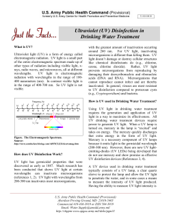


© Copyright 2026