
Chaotic synchronization of a secure system based on
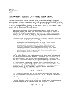
2015, 4th International conference on Modern Circuits and System Technologies
Chaotic synchronization of a secure system
based on one-dimensional iterated maps
John Kalomiros, Costas Hilas
Stavros G. Stavrinides
Department of Informatics Engineering
Technological & Educational Institute of Central Macedonia
Serres, Greece
[email protected], [email protected]
Computer Science Department
University of Thessaly
Greece
[email protected]
Abstract—The design of a secure, digital communication
scheme based on the chaotic iterations of the logistic map is
proposed. A two-stage encryption technique encapsulates
encrypted initial conditions in a synchronization interval and
produces a keystream varying with the plaintext, at sampling
clock rate. A proof of concept is provided by means of
simulation. The overall coincidence probability, demonstrated by
the system depends on the accuracy of the fixed-point
calculations.
Keywords—Digital chaotic circuit, logistic map, chaotic
synchronization, secure communication, chaotic encryption.
I.
INTRODUCTION
During the last decades, applications of complexity and
nonlinear dynamics are increasingly becoming of interest to the
engineering community [1]. Electronics could not be the
exception; next to numerous chaotic circuits implementing
nonlinear systems, a number of applications in the area of
chaotic communications has emerged [2]. The current
technological trend seems to help the design, study and
development of applications based on nonlinear circuits.
The applications based on chaotic electronic circuits, which
have been proposed till now, regard mainly secure
communications or ultra-wideband (UWB) data transmission.
In most cases, analog circuits are employed [3], while a few
mixed-signal circuits have also been proposed [4]. Some digital
chaotic circuits have appeared in the literature [5], [6], but no
real communication system has been presented. In all these
cases, there is a set of nonlinear differential or difference
equations behind the circuit operation [4]-[6]. Recurrent
relations, such as the logistic map, are also another option for
creating chaos. Their fundamental characteristics, like
ergodicity and high sensitivity to the initial conditions, have
been exploited in the quest for cryptographic systems [7].
Synchronization of chaotic circuits is important in secure
communications. In general, accurate transmitter-receiver
synchronization can reproduce the chaotic signal in the
receiver, when the parameters of the transmitting chaotic
circuit are known exactly. Synchronization of chaotic circuits is
an active research field and several applications have been
presented in the literature with regard to secure
communications [2], [5], [6].
In this brief, a synchronization method between digital
chaotic circuits is reported, based on iterated maps. The
proposed concept can be applied to signal encryption and to
wideband communication applications. The algorithm makes
use of a sporadic synchronization bit (sync-bit) encoded in the
transmitted signal as the most significant bit of a
synchronization interval. In this interval the current iteration
value is encrypted, to serve as the initial value for the
forthcoming iterations. In a second procedure, based on the
logistic map, the plaintext is encrypted. The sync-bit is detected
at the receiver and enables the recovery of the proper initial
condition, with the required accuracy. The keystream
encrypting the plaintext is consequently recovered. In this
version of the algorithm, fixed-point calculations are employed
and therefore the algorithm is better suited for dedicated
processors.
The main advantage of the algorithm is that the keystream
is varying with the plaintext, since a new key is produced at
each step. Therefore the system has a level of protection
against attacks with known plaintext. A second advantage is
the speed of the proposed scheme, since the keystream is
produced at sampling clock rate. In principle, any recurrent
relation can be used with the proposed method, in order to
produce the keysteram. In the following sections, details on the
proposed signal encryption and synchronization procedure are
presented. A simulation of the proposed digital communication
system is also given.
II.
COMMUNICATION SYSTEM – PRINCIPLE OF OPERATION
The encryption principle and the operation of the
transmitter-receiver modules appear below.
A. The iterated map
The logistic map is utilized as a recurrent relation able to
produce a chaotic time-series. It is a well-known mathematical
model expressing biological population growth and it is
described by the following equation:
xn+1 = Axn (1 − xn ) ≡ f A ( xn ) ,
(1)
where variable xn stands for the population at the nth time
instant, as a fraction of its maximum value; therefore it lies
within the range 0≤ xn ≤1. The xn time series, resulting from the
above recurrent relation, is strongly dependent on parameter A,
which can obtain values in the range 0≤A<4. Using A as the
control parameter, the logistic map produces a bifurcation
diagram, which for A>3.57 leads to chaos, with divergent
nearby trajectories [8].
The following variation of the logistic map can also be used:
2015, 4th International conference on Modern Circuits and System Technologies
xn +1 = Axn − Bxn2 ≡ f AB ( xn ) ,
(2)
where A and B are both control parameters and define the
resulting time-series. The use of two parameters in eq. (2)
increases the strength of the keystream against adversary
attacks, since one cannot derive both parameters from (2) in an
independent way. A superposition of iterated maps can also be
used [9].
The evolution of the chaotic time series produced by the
above quadratic relation is also dependent on the initial value
of variable xn (the current population). Even a small fractional
difference between two possible starting values, results in two
totally different time-series; this is because the xn trajectories
divert exponentially with regard to their initial conditions. On
the other hand, the fractional accuracy of the calculations also
plays an important role in the reproduction of the chaotic
sequence fA or fAB. Varying the fixed-point accuracy affects
both the time evolution of the iterations and the chaotic content
of the time-series. Better accuracy can ensure that the
trajectories do not follow the same route in the foreseeable
future, presenting a rich chaotic content, suitable for the
production of a cipher-key.
B. The encryption process (Transmitter)
The proposed encryption method is based on the creation of
a keystream in parallel with the plaintext; the cipher keystream
is produced by the logistic map operating in a chaotic mode,
employing fixed-point calculations. A sporadic synchronization
process encapsulates the exact initial value of the chaotic
sequence in encrypted form. The synchronization of the
iterations between the sender and the receiver is an
asynchronous process, repeated at a minimum of L samples. At
each sampling interval a new key is produced by the current
iteration of the map.
The digital samples (or plaintext) of the information signal
are produced with sample rate fs and with N-bit analysis.
Apparently, this could be the output of an A/D converter, in the
case of analog information, or the digital output of a storage
device. The information signal or plaintext is denoted by m.
The encryption circuit produces the logistic sequence fA,
using multipliers with k fractional bits, where k>N. Thus, the
encryption keys related to the computation of the logistic map
keystream is first, the logistic map parameter A, given in (1).
This parameter is defined with k-bit fractional accuracy.
Another N-bit encryption key denoted as b is also produced,
according to a second encryption process, as explained in the
next paragraphs. The main idea of the algorithm is that the
information samples or plaintext are ciphered using as key the
N lower bits of the chaotic sequence values, while sporadically,
the current value of the logistic map sequence f is also
encapsulated in a ciphered form, at the synchronization
interval. This value can then serve as a starting value in the
receiver.
At each sampling step, the encryption algorithm produces a
ciphered output Tn, by the following steps:
(i) At the n-th sampling interval, a new value xn is produced by
the logistic map according to (1), within the range 0< xn <1 and
with a fractional accuracy of k-bits. This value is denoted
as x nk .
(ii) The N least significant fractional bits of x nk are extracted
and form an integer number in the interval [0, 2N-1]. This
integer value is the cipher key and is denoted as c nN . The
x nk fractional value is stored in a register, in order to return as
input for the computation of the next value x nk+1 of the iterated
sequence, in the next sampling interval. Since the N least
significant bits are selected for the key value c nN , the same key
is attributed to many x values.
(iii) The cipher process consists of a bitwise XOR function
between the current sample of the information signal mn and
the current integer key, as this appears in (3):
jn = mn ⊕ cnN .
(3)
This bitwise XOR operation decorrelates signal j from
information signal m, achieving the required signal encryption.
The information signal can be recovered in the receiver
following the reciprocal procedure.
(iv) Prior to transmission, the binary jn value is extended to
N+1 bits. The new bit is the most significant bit and is used for
synchronization purposes. If the current interval is not a
synchronization interval, then the N+1 bit of the jn value is zero
and jn is transmitted using a digital modulation procedure. In
this case the transmitted signal T is defined as follows:
Tn ( N − 1 to 0 ) = j n and Tn ( N ) = 0
(4)
The formation of the synchronization intervals is explained
in the following steps:
(v) In every sporadic instance of a synchronization interval
(sync), the following relation is fulfilled:
Ts ( N ) = 1 ,
(5)
where index s denotes the sync interval. The fractional
accuracy of the x nk value at n=s is rounded down to N bits in the
transmitter and the corresponding integer value in the interval
[0, 2N-1] is denoted as xisN .
(vi) The key value xisN of the iterated sequence is then bitwise
XOR-ed with a new encryption key bs, defined as an integer
with N-bit analysis, which is used in this step in order to cipher
the initial value:
g n = s = xisN ⊕ bs
(6)
where bs is different at each sync interval. The procedure
leading to the encryption key bs is discussed in step (vii) of the
algorithm.
The transmitted signal at the sync interval is now defined as
follows:
Tn = s ( N − 1 downto 0 ) = g n = s and Ts ( N ) = 1 (7)
Signal gs is encoded in the N lower bits of the synchronization
interval. The value of xn=s is computed from the logistic map in
this interval with N-bit analysis in both the transmitter and the
receiver and constitutes the initial value for the next iteration
2015, 4th International conference on Modern Circuits and System Technologies
steps of the logistic map. Since a plaintext character m cannot
be encoded in this interval, as was in stage (iv), its value should
be derived indirectly. It is proposed that the synchronization
interval occurs at the lth appearance of a character, defined by
an exact statistical process. l is natural (l=1,2,3,…). Such
statistical process can be the computation of the character with
the maximum frequency of appearance (the “maximum
likelihood” mml) in an interval of L iterations. The “maximum
likelihood” character mml can be calculated among L
consecutive samples, where a 2N-bin histogram of m values is
computed and the peak m value is extracted. Alternatively, the
easier “running mean” mrm can be computed among L samples.
The running mean is used on the condition that the produced
samples m cover the whole quantum range. After the mml or
mrm is found, the sync interval is transmitted at the lth
occurrence of the mml or mrm character. L and l are predefined
and agreed between the transmitter and the receiver. Then, the
procedure is repeated for the next L samples. The computation
of the mml or mrm character should run in both the transmitter
and the receiver, immediately after the appearance of a sync
interval, when the chaotic sequence has been recovered at the
receiver.
It is noted that the initial value can be recovered in the
receiver with only N-bit accuracy, since this is the defined bit
analysis of each transmitted sample. Therefore, the transmitter
reduces this particular xn value to the required N-bit accuracy
in xi nN , by rounding up the k-bit value at the sync interval. The
logistic sequence that follows is computed with k-bit accuracy,
but is dependent on this N-bit starting value. In all other
intervals, the c nN value is used to form signal j in (3). In this
way, the information signal m and cipher key c share the same
number of bits.
An alternative technique to encapsulate the encrypted initial
value gs is also proposed. Immediately after the occurrence of
one sync interval, a series of N additional sync intervals occur.
In all N+1 intervals, the jn value, as it is defined in (3), is
encoded in the N lower bits of each Tn sample. The Nth bit of
the first sync interval operates as a “start bit” in a serial
Fig. 2. The main stages of the digital chaotic receiver.
sequence, while each MSB bit of the N following samples
encodes one bit of the gs value, in a serial form. Applying this
alternative step, it is also possible to capture the full k-bit
accuracy (instead of the N-bit explained above) of the starting
value in the serial sequence that follows the first sync interval.
A k+1-bit serial to parallel shift register can produce the
starting value after a delay of k+1 clock pulses. The first sync
interval in the serial sequence occurs following the same
statistical considerations presented above.
(vii) In this step the production of the encryption key bs is
discussed. This can be the output of a predefined Look-Up
Table (LUT) shared by the sender and the receiver. The input
of the LUT is the number of steps q-L, where q, is the number
of samples counted in the transmitter and the receiver between
consecutive sync intervals. The depth of the LUT depends on
the range of q-L.
Another option is to produce bs as the output of the (q-L)th
iteration of a second logistic map, with control parameter and
initial value shared by the sender and the receiver as secret
keys. The iterations are reset immediately after a sync interval.
A simplified block diagram of the transmitter according to
the previous steps is shown in Fig. 1.
C. The deciphering process (Receiver)
Signal jn forms the basis of the transmitted ciphered signal.
It cannot be deciphered unless the receiver possesses exactly
the same key cn at each sampling interval. In this case, the
bitwise XOR operation of signal jn with the correct c nN value,
returns the initial information signal:
mn = jn ⊕ cnN
(8)
In order to recover the signal in the receiver, an identical
arithmetic block performing the logistic sequence calculations
according to (2) is required. Both the transmitter and the
receiver blocks need to share the knowledge of the encryption
keys A, B as well as the knowledge for the production of b at
the sync interval. As soon as a synchronization bit is detected,
the receiver sets in the deciphering process. The bs value is
derived following step (vii) and the xinN= s value is recovered
according to:
xisN = bs ⊕ g s
(9)
Then, the logistic block in the receiver reproduces the f
sequence, i.e. the x nk values. At each sampling interval the N
least significant fractional bits of x nk are extracted and form the
Fig. 1. Digital chaotic transmitter block diagram.
integer cipher key value c nN . Then, the information signal is
recovered by (8). A simplified block diagram of the proposed
receiver is shown in Fig. 2.
2015, 4th International conference on Modern Circuits and System Technologies
(a)
Fig. 5. m(n) vs. m’(n) graph as derived in the case of Fig 4(a). All points rest
on the diagonal depicting full synchronization.
(b)
Fig. 3. (a) Information input signal and (b) The logistic map block output
III.
EVALUATION OF SYNCHRONIZED COMMUNICATION
A Matlab/Simulink, bit-accurate implementation of the
above described digital secure communication system is tested,
in order to evaluate its synchronization robustness.
An analog sine signal shown in Fig. 3(a) is driving the
transmitter circuit. The analysis of the samples of the
information signal is N=10 bits. The fractional accuracy in the
calculations of the logistic map is k=20 bits. In this simulation,
eq. (1) was used and therefore, we refer only to parameter A.
The output of the logistic map block is shown in Fig. 3(b).
Parameter A at the logistic map block of the receiver can be
varied, while it is kept constant at the transmitter.
At the beginning, parameter A is considered to be identical
in both the transmitter and the receiver and possesses the value
A=3.900000. The information signal is demodulated accurately
at the receiver, and keeps being synchronized at all
synchronization intervals. The demodulated information signal
appears in Fig. 4(a). At the beginning, the receiver has not
synchronized and the output is chaotic. Then, the receiver is
synchronized. In this example, the running mean is computed
within L=32 samples. After each synchronization interval, the
receiver derived the initial value and the signal was properly
demodulated, according to equation (8).
In Fig. 4(b), parameter A at the receiver was set to
A=3.900001, thus presenting a difference of 1E-6. This time
the receiver failed to demodulate the information signal.
Apparently, the values at the output of the logistic map blocks
in the transmitter and the receiver diverge one from the other
very fast, after each synchronization interval.
In Fig. 5 the synchronization phase portrait m(n) vs. m΄(n) in
the case of Fig. 4(a) appears. All points rest on the diagonal,
clearly depicting full synchronization between transmitter and
receiver (for A=3.900000).
Finally, it is noted that the studied communication system
was also tested in the case of the superposition of three sine
signals differing in frequency. The system exhibited robust and
continuous synchronization in this case, as well.
IV.
A digital communication scheme based on logistic map
iterations was designed and simulated in Matlab/Simulink
environment. The map chaotic iterations were utilized as a
keystream in the transmission of plaintext information. The
same iterations were reproduced in the receiver utilizing
chaotic synchronization between transmitter and receiver. A
synchronization interval is proposed, encapsulating the
starting value of the iteration sequence in encrypted form.
Synchronization and recovery of the initial value results in the
proper recovery of the information signal in the receiver. The
proposed method could also be applied with other iterated
maps or nonlinear difference equations presenting chaotic
behavior.
REFERENCES
[1]
[2]
[3]
[4]
[5]
(a)
[6]
[7]
[8]
(b)
Fig. 4. Output of the receiver in the case of (a) identical values for parameter
A in both the transmitter and the receiver and (b) for a difference of 1E-6.
CONCLUSION
[9]
S. Banerjee, L. Rondoni Eds, Applications of chaos and nonlinear
dynamics in science and engineering, vol. 1, 3, and 3, Springer, 2013.
M.P. Kennedy, R. Rovatti, G. Setti, Chaotic Electronics in
telecommunications, CRC Press, 2000.
A.S.Dmitriev et al, "Amplitude modulation and demodulation of chaotic
carriers," in Proc. NDES'2004, Evora, Portugal, 2004, pp. 138-141.
A. N. Miliou, et al, “Nonlinear electronic circuit–PART II:
Synchronization in a chaotic MODEM scheme,” Nonlin Anal: Theory,
Methods and Applications, vol 71, pp. e21-e31, 2009.
A. J. Michaels, “A maximal entropy digital chaotic circuit,” in Proc.
2011 IEEE International Symposium on Circuits and Systems – ISCAS,
Rio de Janeiro, Brazil, 2011, pp. 717-720.
S.G. Stavrinides et al, “A digital nonautonomous chaotic oscillator
suitable for information transmission,” IEEE TCAS II, vol. 60, no. 12,
2013.
A.N. Pisarchik, M. Zanin “Chaotic map cryptography and security”, in
Encryption: Methods, Software and Security, Nova Science Publishers,
Inc, 2010.
R. Hilborn, Chaos and Nonlinear Dynamics, An introduction for scientists
and engineers, Oxford University Press, 1994.
[9] P. Li, Z. Li, W.A. Halang, G.A. Chen, Chaos, Solitons & Fractals, 32,
2007, pp. 1867-1876.


© Copyright 2026