
Produced and Flowback Water Recycling and Reuse Economics, Limitations, and Technology
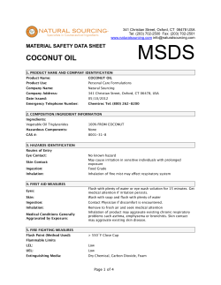
Produced and Flowback
Water Recycling and Reuse
Economics, Limitations, and Technology
Pam Boschee, Oil and Gas Facilities Senior Editor
The demonstration site for the Altela thermal distillation
process was located at BLX's Sleepy wellsite in the
Marcellus shale. Photo courtesy of Altela.
T
he demands for the fresh water used in many
hydraulic fracturing operations are placing pressure
on water sources in some regions of the United
States. Because of the high volumes of water needed
for fracturing (e.g., in the Marcellus, a typical hydraulic
fracturing operation for a horizontal gas well in a tight shale
formation requires from 3 to 5 million gallons of water
over a 2- to 5-day period), the competing demand driven
by industrial, municipal, and agricultural users has in some
cases decreased the availability of fresh water and increased
associated costs.
Along with higher acquisition costs for fresh water,
water disposal costs have also increased. Well stimulation
flowback water and produced water are generally
considered as waste byproducts of oil and gas production
and increasingly present logistical difficulties for operators.
Among the challenges are the transportation of the water
over long distances and compliance with local jurisdictions
and environmental regulations related to the disposal of
water from oil fields.
Operators are using alternative methods of water
management, including recycling and reuse of their flowback
and produced water, to help reduce the total amount of fresh
water that is used in their operations, and at the same time,
reduce the volumes of flowback and produced water that
have to be transported, treated, and disposed.
Life Cycle Water Costs From
Acquisition to Disposal
Walter Dale, the strategic business manager for water
solutions at Halliburton, said that the availability of fresh
water, transportation costs, water treatment, and disposal
costs may come to mind first as the major factors in water
economics. However, the total cost of water needs to be
considered, including acquisition, transfer to the well,
transfer from the well to disposal, and disposal (Table 1).
Once the fracturing procedure itself is completed,
water returns to the surface as produced water, the naturally
occurring water found in shale formations that flows to
the surface throughout the entire production lifespan of
TABLE 1—VARIATIONS IN TOTAL WATER COST
Producing Area
Total Cost/bbl (USD)*
Bakken
6.00 to 15.00
Eagle Ford
2.00 to 6.00
Permian Basin
3.00 to 8.00
Marcellus
4.00 to 20.00
Denver-Julesburg
4.00 to 8.00
*Total cost/bbl does not include the cost of brine
addition.
Source: Halliburton 2014.
the well, and flowback, the fraction of hydraulic fracturing
fluid recovered.
The fraction of hydraulic fracturing fluid recovered
varies from play to play (Table 2). For example, flowback
fluid recovered from wells is reported to range from 9% to
35% of the fracture fluid used in the horizontal Marcellus
wells in the northern tier of Pennsylvania (Wood et al.)
Yoxtheimer (2010) reported an average recovery of flowback
of 10% (over 30 days) per Marcellus well. Ultimately, from
300,000 gal to 800,000 gal/well of wastewater are produced.
Industry data reported to the Pennsylvania Department
of Environmental Protection show that about 235 million
gallons of wastewater were produced in the second half of
2010 (Penn State).
Data compiled by the state of Pennsylvania indicates
that the volume of flowback water generated from Marcellus
wells in 2012 was about three times the volume of produced
water. As more wells go into production, the amount of
produced water will increase, and the ratio will begin to
change. While the volume of flowback water is expected
to remain at approximately 2.5 billion gal/yr until 2019,
TABLE 2—fraction of hydraulic fluid and produced water returned to surface
Producing Area
Fraction of Hydraulic Fracturing Fluid Returned as Flowback, % Produced Water Volumes
Bakken
15 to 40
High
Eagle Ford
<15
Low
Permian Basin
20 to 40
High
Marcellus
10 to 40
Moderate
Denver-Julesburg
15 to 30
Low
Source: Halliburton 2014.
February 2014 • Oil and Gas Facilities
17
TABLE 3—average tds found in flowback
and produced water
Producing Area
TDS, mg/L
Bakken
150,000 to 300,000
Eagle Ford
15,000 to 55,000
Permian Basin
20,000 to 300,000
Marcellus
20,000 to 100,000
Denver-Julesburg
20,000 to 65,000
Source: Halliburton 2014.
the amount of produced water is forecast to rise steadily
until it surpasses the amount of flowback water in 2019 at
2.7 billion gal.
Options for Flowback and Produced
Water Management
Flowback water management options include direct reuse
without treatment (blending with fresh water for reuse in
hydraulic fracturing); on-site treatment and reuse; off-site
treatment and reuse; and off-site treatment and disposal.
Direct reuse incurs minimal cost, but results in the
potential for well plugging. On-site treatment reconditions
the water at a moderate cost and has a decreased potential
for well plugging. Off-site treatment and reuse incurs high
transportation costs, while off-site treatment and disposal
incurs high transportation and disposal costs.
Disposal using injection wells is limited in many areas.
Pennsylvania currently has about seven brine disposal
wells. Only one is a commercial well, and it has limited or
no available capacity and is not permitted for Marcellus
wastewater disposal. New York has six brine disposal wells,
West Virginia has 74, and Ohio has 159. Issues in geological
formations make it difficult to site the disposal wells in
Pennsylvania and West Virginia (Penn State).
Of the approximately 250 injection wells serving the
Marcellus play, approximately three-fourths of the deep
injection wells are located in Ohio. Ohio state records show
that of the 12.2 million bbl of waste and brine disposed
in its deep injection wells in the first half of 2012, 56%
of the disposed materials came from Pennsylvania and
West Virginia.
Shifting the TDS Paradigm
A primary concern in oilfield water treatment is the level of
total dissolved solids (TDS) in flowback and produced water,
which varies by basin and well (Table 3). TDS is a measure
of dissolved matter in water, such as salts, organic matter,
and minerals. Inorganic constituents (sodium, calcium, and
18
Oil and Gas Facilities • February 2014
chloride picked up from the rock formation) contribute
most of the total concentration of TDS.
Under the federal Safe Drinking Water Act, the US
Environmental Protection Agency classifies TDS as a
secondary maximum contaminant level (sMCL), meaning
that there is a recommended maximum level of 500 mg/L,
but no requirement that public water systems meet this
level. However, states may enforce their own secondary
standards. TDS is not expected to harm human health at the
sMCL, but elevated TDS levels may damage water treatment
equipment or reduce the effectiveness of treatment for other
contaminants. TDS becomes toxic to aquatic life at certain
levels by increasing the salinity in freshwater systems and
changing the composition of the water.
Dale said operators are reevaluating their approaches
to treating water for TDS removal when aggregating their
flowback and produced water to be recycled for use in
hydraulic fracturing completions. General approaches to
handling the TDS variability include the following:
•T
reatment of the water to achieve high quality
standards by removing boron, calcium, etc. This
approach may result in increased costs and increased
waste creation, leading to the conclusion that recycling
is too expensive to implement.
•D
ilution of the water with fresh water, which
may result in the misapplication of treatment
technologies that result in well production or fluid
integrity concerns.
Many treatments do not remove dissolved salts from
the water, thus requiring the development of brine-tolerant
fracturing fluid systems and friction reducers or the use of
distillation to maintain high performance.
The cost of purifying flowback and produced water to
near potable quality might not be financially feasible, while
bypassing treatment entirely can pose difficulties in using
the water effectively for fracturing fluids, Dale said.
The compositions of fracturing fluids vary from one
product to another, and the design of the fluid varies,
depending on the characteristics of the target formation and
operational objectives. The predominant fluids currently
being used for fracture treatments in the gas shale plays are
water‐based fracturing fluids mixed with friction‐reducing
additives (slickwater), linear gel, and crosslinked gel.
The fracturing fluid used in slickwater operations
typically comprises about 98% water and sand (as a
proppant), with additives (e.g., friction reducer, biocide,
surfactant, scale inhibitor, breaker, and clay stabilizer)
comprising 2% (Ketter et al. 2006). Polyacrylamide polymers
are used to reduce the tubular friction pressure (friction
reducers). Overall, the concentration of additives in most
slickwater fracturing fluids is 0.5% to 2% with water making
up from 98% to 99.5% of the volume. Because of its low
viscosity (from 2 to 3 cP), a high pump rate is required to
transport proppant in the formation.
Linear gel is water containing a gelling agent, like guar
or xanthan. Other possible additives are biocides, buffers,
surfactant, breaker, and clay control. Its viscosity, ranging
from 10 to 30 cP, results in improved proppant transport
compared to slickwater.
Crosslinked gel is water containing any of the gelling
agents used in linear gel and a crosslinker like boron,
zirconium, titanium, or aluminum. Other possible additives
are buffers, biocide, surfactant, breaker, and clay control.
This fluid has a high viscosity, ranging from 100 to 1,000
cP, which generally results in better proppant transport
compared to slickwater and linear gel fracture fluids.
Development of crosslinked gel-based water systems,
such as Halliburton’s UniStim service, which tolerates salt
concentrations in excess of 300,000 mg/L, has enabled
operators to use 100% flowback, produced water, and
alternate sources, Dale said.
To reuse high-TDS water effectively in crosslinked
gel-based hydraulic fracturing fluids, the water must first be
treated. The goal of the treatment is to remove only minerals
that hinder the development of the crosslinked fluid or that
cause scale buildup in wells, he said. In these cases, treatment
is done to the extent required to ensure production and fluid
integrity, creating less waste for disposal.
The development of high-TDS tolerant friction reducers
has resulted in cost advantages by reducing the amount
of polymer required in slickwater. Case studies of wells in
Canada’s Montney and Horn River shale plays that were
treated with brine-tolerant friction reducers demonstrated
that their performance in brines was similar to that
achieved with conventional friction reducers in fresh water
(Paktinat 2011).
An example of the cost benefits associated with
freshwater conservation were based on a Montney well
located in northeastern British Columbia, where production
water was used after commingling with freshwater sources.
The total amount of water required for the well (20 zones)
was about 340,000 bbl. Using flowback water and assuming
two cases of 30% and 50% fluid recoveries, from 113,000
bbl to 170,000 bbl of fresh water could be saved per well. By
using a brine-tolerant friction reducer and with reuse of all
flowback water, the estimated savings were about USD 1.4
million for the treatment of one well. The estimate assumed
that no water was sent for disposal (Tables 4 and 5).
One Size Does Not Fit All
Dale said that the decision to recycle flowback and produced
water is dependent upon the economic factors for each
operator. The number of wells, amounts of flowback and
produced water, and the proximity of these sources for
aggregation are important factors in determining water
management. “The ability to recycle high volumes of water
is the goal. It’s a function of how much available impaired
water you have in proximity.
“When the Bakken first started, there were insufficient
water volumes to consider recycling. But with the increased
rig count, the flowback volumes are higher, and it makes a
lot of produced water now that it’s a few years old. Operators
TABLE 4—total cost of one well in
montney shale using only fresh water
$/bbl
Volume, bbl
Total Cost, $
Trucking +
3.35
fresh water cost
339,606
1,137,680
Flowback
disposal cost
8.00
169,803
1,358,424
Cost to recycle/
reuse flowback
+ transfers
2.75
0
0
Total cost/well
2,496,104
Source: Paktinat et al 2011.
TABLE 5—total cost of one well in
montney shale using only fresh water
and flowback water (50% Fracturing
fluid recovery)
$/bbl
Volume, bbl
Total Cost, $
Trucking + fresh 3.35
water cost
165,803
568,840
Flowback
disposal cost
8.00
0
0
Cost to recycle/
reuse flowback
+ transfers
2.75
165,803
466,958
Total cost/well
1,035,798
Note: Total volume of water used was 339,606 bbl
(50% fresh, 50% of flowback)
Source: Paktinat et al 2011.
are hauling 12 million bbl of water to disposal wells, while
they are using 9 million bbl of fresh water. It’s not practical
to use the entire volume of 12 million bbl of the disposal
water to replace the 9 million bbl of fresh water. It’s about
proximity,” Dale said.
In locations where the flowback and produced water
volumes are not high, aggregation will eliminate disposal
and acquisition of one barrel of fresh water for every barrel
that is reused. He said, “You’re also going to reduce your
brine purchase and reduce double-trucking costs.”
February 2014 • Oil and Gas Facilities
19
In the Permian Basin, older conventional wells
are producing high volumes of water and are tied by
gathering lines to a central disposal facility. Dale described
a customer’s effort to develop a hub and spoke model to
accommodate an entire field, which was too large for the
model to be economically feasible. “The reality was that the
customer had the most volume of water production, not in
the center of the spoke, but in the top right-hand quadrant
of the spoke. In this case, it makes sense to recycle in that
quadrant, but doesn’t make sense to recycle in the bottom
left-hand quadrant.”
Dale said that operators should look for alternate
sources of water in proximity to their unconventional
completions that require high volumes of water. “Look for
the high volumes of impaired waters, such as flowback,
produced water, and brackish water wells.”
He said an operator with a project located near a
refinery is considering aggregating its flowback, produced
water, and brackish water with water available from the
refinery. In this case, the refinery’s water quality is suitable
for making fracturing fluids.
Increasingly, asset managers are becoming the decision
makers in an organization’s water recycling approaches.
Dale said, “Some organizations are realizing this. The senior
executives want to recycle, but the completions engineers
don’t have the budget for it. These decisions are beginning to
involve the P&L (profit and loss) people in the company.”
Water Treatment Technologies
Two broad classifications of technologies available for
treatment and reuse of flowback and produced water are
conventional treatment and advanced treatment technology,
both of which have environmental, economic, and energy
effects that are related to the quality of flowback and
produced water.
Conventional treatment includes flocculation,
coagulation, sedimentation, filtration, and lime softening
water treatment processes. These methods are generally
effective in removing nondissolved constituents, such
as total suspended solids, oil and grease, and hardness
compounds. Although conventional processes can be
energy-intensive, they are typically less energy-intensive
than the salt separation treatments, which will be discussed
below. Simple filtration methods with minimal chemical
inputs have lower energy, environmental, and economic
effects.
Advanced treatment technologies, such as reverse
osmosis membranes, thermal distillation, evaporation
and/or crystallization processes, are used to treat TDS.
The thermal and membrane processes require more
energy than the conventional methods. Additionally, in
most cases, conventional processes are used upfront to
remove the nondissolved constituents prior to the TDS
treatment processes.
A recently introduced technology for water deslination/
decontamination in the Marcellus shale play implements
20
Oil and Gas Facilities • February 2014
an internal heat transfer process that allows the reuse of the
latent heat of condensation to offset the total latent heat of
evaporation required in conventional thermal distillation.
Incoming dirty water is converted into clean distilled water
and a concentrated solution of dirty water (Fig. 1).
By recapturing the energy used to evaporate water, the
AltelaRain process yields about four times the amount of
distilled water per energy input as tradition distillation/
evaporation techniques without using pressure (Bruff and
Jikich 2011).
The process begins with the produced water that is
collected in an on-site holding tank. Following its transfer
by pump to a containerized system, the produced water
is circulated continuously through 10 towers. The towers
are designed to evaporate pure water from the brackish
produced water. The evaporated water is then condensed
within the same tower, on the opposite side of thin
plastic sheets.
The condensed water, which is of distilled water
quality, is collected and transferred from the towers to a
distilled water holding tank. The concentrated water is
eventually concentrated up to five times higher TDS content
and then pumped out of the system for disposal. The
distilled water is also pumped from the system and made
available for recycling and reuse. The water quality of the
treated distilled water meets or exceeds the Pennsylvania
Department of Environmental Protection’s water quality
discharge requirements.
Two wastewater treatment facilities using the
technology are located in western Pennsylvania. The facility
located in McKean county is owned and operated by
Casella-Altela Regional Environmental Services. Situated
adjacent to the McKean county landfill, the facility uses
landfill gas as its energy source. Owned and operated by
Clarion Altela Environmental Services, the facility located
in Clarion county uses waste heat from the waste-coal-fired
Piney Creek Power Plant.
Each facility is able to process up to 12,000 B/D (about
500,000 gal) of wastewater, which can then be reused for
well operations or discharged into surface waterways.
Bruff and Jikich (2011) reported the total treatment
cost as USD 5.29/bbl at the completion of a National
Energy Technology Laboratory (NETL) demonstration
project in 2011, prior to the technology’s implementation
at the wastewater treatment facilities. The cost included
the trucking and disposal of the concentrated dirty water.
This total cost represented a savings of 16% compared
to trucking and disposal costs without treatment by the
system. The authors noted that real-world savings would
be larger, because of the high labor costs involved with the
NETL demonstration project. OGF
Oil and Gas Facilities has published a series of in-depth
articles about water management for unconventional
resources in the Water Treating Insights column. The
first article was published in June 2013. This month,
Saturated carrier gas
Waste heat or steam input
Heat
Exchange
Brackish produced water stream
Energy reuse
(without a pressure vessel)
Condensation chamber
Evaporation chamber
Microthin noncorrodible thermally
conductive water-impermeable wall
Exit air
Distilled water stream
Ambient air
Heat
Exchange
Concentrated water stream
Fig. 1—Altela's thermal distillation process heats wastewater to produce clean water vapor by using an internal heat transfer process
that reuses the latent heat of condensation to offset the total latent heat of evaporation required in conventional thermal distillation.
Image courtesy of Altela.
methods of controlling biological activity in hydraulic
fracturing operations are discussed.
For Further Reading
SPE 103232 A Field Study Optimizing Completion
Strategies for Fracture Initiation in Barnett Shale
Horizontal Wells by A. Ketter, Devon Energy et al.
SPE 149272 Case Studies: Impact of High Salt Tolerant
Friction Reducers on Fresh Water Conservation in
Canadian Shale Fracturing Treatments by J. Paktinat, et
al., Trican Well Service.
SPE 149466 Field Demonstration of an Integrated Water
Treatment Technology Solution in Marcellus Shale by M.
Bruff, Altela, and S.A. Jikich, US Department of Energy/
National Energy Technology Laboratory.
ALL Consulting, 2009. Horizontally Drilled/High-Volume
Hydraulically Fractured Wells Air Emissions Data.
Bruff, M., Godshall, N., and Evans, K. 2011. An Integrated
Water Treatment Technology Solution for Sustainable
Water Resource Management in the Marcellus Shale.
Final Scientific/Technical Report DE-FE0000833.
Penn State College of Agricultural Sciences Cooperative
Extension. 2011. Marcellus Shale Wastewater Issues in
Pennsylvania—Current and Emerging Treatment and
Disposal Technologies. http://extension.psu.edu.
Susquehanna River Basin Commission, 2012. SRBC'S Role
in Regulating Natural Gas Development, http://www.srbc.
net/programs/docs/NaturalGasFAQ_20120323_140574v1.
pdf.
Wood, Ruth, et al. 2011. Shale Gas: A Provisional
Assessment of Climate Change and Environmental
Impacts. The Tyndall Centre, University of
Manchester, http://www.landbou.com/content/
uploads/ArticleDocument/e117d35e-263d-4e94-9c2702199efbc60c.pdf.
Yoxtheimer, D. 2010. Water Management Options for
Marcellus Natural Gas Development. Penn State College
of Agricultural Sciences Cooperative Extension, Marcellus
Shale Educational Webinar Series. http://extension.psu.
edu/.
February 2014 • Oil and Gas Facilities
21
22
Oil and Gas Facilities • February 2014


© Copyright 2026