
Hydro MPC, ASEAN range
GRUNDFOS DATA BOOKLET Hydro MPC, ASEAN range Booster systems with two to six pumps 50/60 Hz Hydro MPC, ASEAN range Table of contents 1. 2. 3. 4. 5. 6. 7. 8. 9. 2 Product introduction 3 10. Technical data, Hydro MPC-E/-S (50 Hz) 55 Applications Benefits 3 3 Product data 5 Hydro MPC-E/-S with CR, CRI 3 / CR, CRI 5 Hydro MPC-E/-S with CR, CRI 10 Hydro MPC-E/-S with CR, CRI 15 / CR, CRI 20 Hydro MPC-E/-S with CR 32 Hydro MPC-F/-S with CR 45 / CR 64 Hydro MPC-E/-S with CR 90 55 58 62 68 71 76 11. Technical data, Hydro MPC-E/-S (60 Hz) 79 Hydro MPC-E/-S with CR, CRI 3 / CR, CRI 5 Hydro MPC-E/-S with CR, CRI 10 Hydro MPC-E/-S with CR, CRI 15 / CR, CRI 20 Hydro MPC-E/-S with CR 32 Hydro MPC-E/-S with CR 45 / CR 64 Hydro MPC-E/-S with CR 90 79 82 86 91 94 98 Performance range Product range, 50 Hz Performance range Product range, 60 Hz Type key Operating conditions 5 6 7 8 9 10 Construction 11 Pump Shaft seal Motors Manifold Control cabinet CU 352 IO 351 Base frame System components Flange dimensions 11 11 11 12 12 12 12 13 13 13 Functions 14 Overview of control variants CU 352 control panel Overview of functions Description of selected functions 14 15 17 18 Installation 24 Mechanical installation Electrical installation 24 25 Sizing 26 Understanding the curve charts Example: How to select a system 32 33 Curve conditions 34 How to read the curve charts 34 Curve charts, Hydro MPC-E/-S (50 Hz) 35 Hydro MPC-E/-S with CR, CRI 3 Hydro MPC-E/-S with CR, CRI 5 Hydro MPC-E/-S with CR, CRI 10 Hydro MPC-E/-S with CR, CRI 15 Hydro MPC-E/-S with CR, CRI 20 Hydro MPC-E/-S with CR 32 Hydro MPC-E/-S with CR 45 Hydro MPC-E/-S with CR 64 Hydro MPC-E/-S with CR 90 35 36 37 38 39 40 41 42 43 Curve charts, Hydro MPC-E/-S (60 Hz) 44 Hydro MPC-E/-S with CR, CRI 3 Hydro MPC-E/-S with CR, CRI 5 Hydro MPC-E/-S with CR, CRI 10 Hydro MPC-E/-S with CR, CRI 15 Hydro MPC-E/-S with CR, CRI 20 Hydro MPC-E/-S with CR 32 Hydro MPC-E/-S with CR 45 Hydro MPC-E/-S with CR 64 Hydro MPC-E/-S with CR 64 Hydro MPC-E/-S with CR 90 Hydro MPC-E/-S with CR 90 44 45 46 47 48 49 50 51 52 53 54 12. Optional equipment Diaphragm tank Redundant primary sensor Dry-running protection Pilot pump Bypass connection Position of non-return valve Stainless-steel non-return valve Repair switch Isolating switch Main switch for neutral conductor Operating light, system Fault light, system Fault light, pump Panel light and socket IO 351B interface Backup battery Ethernet CIM communication interface modules Transient voltage protection Lightning protection Phase-failure monitoring Beacon Potential-free contacts Audible alarm Voltmeter Ammeter 13. Accessories Dry-running protection Diaphragm tank Foot valve Machine shoe Grundfos GO Extra documentation 101 101 101 101 102 102 102 102 103 103 103 103 103 104 104 104 104 104 104 105 105 105 105 105 105 105 105 106 106 106 107 107 107 108 14. Alternative booster systems 109 15. Grundfos Product Center 110 Hydro MPC, ASEAN range 1 Benefits Grundfos Hydro MPC booster systems are designed for transfer and pressure boosting of clean water in places such as: • waterworks • blocks of flats • hotels • industry • hospitals • schools. As standard, the booster systems consist of two to six identical CR or CRI pumps connected in parallel and mounted on a common base frame provided with a control cabinet and all the necessary fittings. You can remove the pumps of the booster system without interfering with the pipework on either side of the manifolds. The booster systems are available in three control variants. For further information, see Product range, 50 Hz on pages 6, Product range, 60 Hz on page 8 and Overview of control variants on page 14. Perfect constant-pressure control Hydro MPC-E Booster systems with two to six identical electronically speed-controlled pumps. Pipework connection from R 2 to DN 350. From 0.37 to 37 kW, Hydro MPC-E is fitted with CR, CRI pumps connected to Grundfos CUE frequency converters (one per pump). Gr1014555 Applications Product introduction 1. Product introduction Fig. 1 CU 352 The pumps are controlled individually by the CU 352 multipump control unit which contains application-optimised software and pump curve data. The CU 352 thus knows the exact hydraulic and electrical data of the pumps to be controlled. Furthermore, a log function enables monitoring of the system performance over a period of time. User-friendliness Hydro MPC features a built-in startup wizard in a wide range of languages that guides the installer through a series of steps until the system is correctly installed and commissioned. When the installation is complete, the large, user-friendly colour display will ensure that day-to-day operation is equally easy. Reliability Hydro MPC-S TM04 4568 1709 Booster systems with two to six identical mains-operated CR, CRI pumps. Pipework connection from R 2 to DN 350 and motor sizes from 0.37 to 37 kW. Fig. 2 Grundfos CR pumps The booster system is built on the highly renowned Grundfos CR pump range. CR pumps are known for their reliability, efficiency and adaptability. Every vital piece of the booster system is made by Grundfos. You are thus guaranteed long-lasting technology that requires a minimum of maintenance and provides a maximum of efficiency. 3 Hydro MPC, ASEAN range 1 Product introduction Low energy consumption All motors used in the booster systems meet the legislative requirements of the EuP IE3 level. Furthermore, the booster system uses pump curve data to calculate and optimise the cut-in and cut-out of pumps. High-efficient motors, advanced control in combination with optimised hydraulics for both the CR pump and the manifold ensures that the system uses a minimum of energy. Flexibility The elements of the booster system can be combined in a number of ways to make sure that we build the perfect solution for you! Custom-built solutions If this data booklet does not provide you with a solution that meets your specific pumping needs, please contact us. 4 Hydro MPC, ASEAN range 2 Product data 2. Product data Performance range + >P@ +\GUR03&(6 +] ,62$QQH[$ [ [ [ [ &5, &5, &5 &5 [ &5, [ &5, [ &5 [ &5 4>PñK@ TM06 3290 5014 [ &5, 5 Hydro MPC, ASEAN range 2 Control variant Frequency PT Hydro MPC-E Hydro MPC-S 50 Hz 50 Hz Hydraulic data Maximum head [m] 144 144 Flow rate [m3/h] 0-720 0-720 Liquid temperature [°C] 0-60 1) 0-60 16 2) 16 2) Maximum operating pressure [bar] Motor data Number of pumps 2-6 2-6 Motor power [kW] 0.37 - 30 0.37 - 30 ● ● CRI/CRN 3 to CRI/CRN 90: Stainless steel EN/DIN 1.4301/AISI 3046) ❍ ❍ CR 3 to CR 90: Cast iron and stainless steel EN/DIN 1.4301/AISI 304 ● ● Manifold: Stainless steel 5) ● ● Shaft seal HQQE (SiC/SiC/EPDM) Materials Pipework connection Union connection R 2 to R 2 1/2 R 2 to R 2 1/2 DN 80 to DN 350 DN 80 to DN 350 Constant-pressure control ● ● 3) Automatic cascade control ● ● Pump changeover/alternation ● ● Stop function ● - Proportional-pressure control ● - Bus communication (external) ❍ ❍ Integrated frequency converter (in pump) ● - External frequency converter (in cabinet) ● - Ethernet connection ● ● Alternative setpoints ● ● Redundant primary sensor (option) ● ● Standby pump ● ● Emergency run ● ● DIN flange Functions ●4) - Log function ● ● Reduced operation ● ● Service contact information ● ● Help texts ● ● Specific energy calculation ● Available as standard. ❍ Available on request. 1) 2) 3) 4) 5) 6) 6 Higher temperature available on request. Booster systems with a maximum operating pressure higher than 16 bar are available on request. The pressure will be almost constant between Hset and Hstop. For further information, see page 14. Requires that a flowmeter has been installed and connected. In some regions, galvanised manifolds are available as an option. For further information, contact Grundfos. CRN: EN/DIN 1.4401 / AISI 316. TM03 0999 0905 PT TM03 0993 0905 Product data Product range, 50 Hz Hydro MPC, ASEAN range 2 + >P@ Product data Performance range +\GUR03&(6 +] ,62$QQH[$ [ [ [ [ &5 &5 &5 &5 [ [ [ [ [ &5 &5 &5 &5 &5 4>PñK@ TM06 3292 5014 7 Hydro MPC, ASEAN range 2 PT Control variant Frequency TM03 0999 0905 TM03 0993 0905 Product data Product range, 60 Hz PT Hydro MPC-E Hydro MPC-S 60 Hz 60 Hz Hydraulic data Maximum head [m] 144 144 Flow rate [m3/h] 0-876 0-876 Liquid temperature [°C] 0-60 1) 0-60 1) Maximum operating pressure [bar] 16 2) 16 2) Motor data Number of pumps 2-6 2-6 Motor power [kW] 0.37 - 37 0.37 - 37 ● ● CRI/CRN 3 to CRI/CRN 90: Stainless steel EN/DIN 1.4301/AISI 3046) ● ● CR 3 to CR 90: Cast iron and stainless steel EN/DIN 1.4301/AISI 304 ● ● Manifold: Stainless steel 5) ● ● Shaft seal HQQE (SiC/SiC/EPDM) Materials Pipework connection Union connection R 2 to R 2 1/2 R 2 to R 2 1/2 DN 80 to DN 350 DN 80 to DN 350 Constant-pressure control ● ● 3) Automatic cascade control ● ● Pump changeover/alternation ● ● Stop function ● - Proportional-pressure control ● - Bus communication (external) ❍ ❍ Integrated frequency converter (in pump) ● - External frequency converter (in cabinet) ● - Ethernet connection ● ● Alternative setpoints ● ● Redundant primary sensor (option) ● ● Standby pump ● ● Emergency run ● ● DIN flange Functions ● 4) - Log function ● ● Reduced operation ● ● Service contact information ● ● Help texts ● ● Specific energy calculation ● Available as standard. ❍ Available on request. 1) 2) 3) 4) 5) 6) 8 Higher temperature available on request. Booster systems with a maximum operating pressure higher than 16 bar are available on request. The pressure will be almost constant between H set and Hstop. For further information, see page 14. Requires that a flowmeter has been installed and connected. In some regions, galvanised manifolds are available as an option. For further information, contact Grundfos. CRN: EN/DIN 1.4401 / AISI 316. Hydro MPC, ASEAN range Type key Example Hydro MPC -E 6 CRE 150-4-5 U1 Type range System type E: All pumps, E motor or CUE F: Fixed-speed pumps, one CUE S: Fixed-speed pumps X: Customised system pumps A- A- A- ABCD Product data 2 Number of main pumps Pump type Voltage code U1 = 3 x 380-415, N, PE, 50/60 Hz U2 = 3 x 380-415, PE, 50/60 Hz U3 = 3 x 380-415, N, PE, 50 Hz U4 = 3 x 380-415, PE, 50 Hz U5 = 3 x 380-415, N, PE, 60 Hz U6 = 3 x 380-415, PE, 60 Hz U7 = 1 x 200-240, PE, 50/60 Hz U8 = 1 x 200-240, N, PE, 50/60 Hz U9 = 3 x 220-240, PE, 60 Hz UA = 3 x 440-480, PE, 60 Hz UB = 1 x 220-240, N, PE, 50/60 Hz UC = 1 x 220-240, N, PE, 50 Hz Design A: Systems with the control cabinet mounted on the same base frame as the pumps. B: Systems with the control cabinet centred on the base frame. C: Systems with the control cabinet mounted on its own base for floor mounting.* D: Systems with the control cabinet mounted on its own base frame.* E: ASEAN design and systems with the control cabinet mounted on the same base frame as the pumps. F: ASEAN design and systems with the control cabinet centred on the base frame. G: ASEAN design and systems with the control cabinet mounted on its own base for floor mounting.* H: ASEAN design and system with the control cabinet mounted on its own base frame.* I: ASEAN design and systems with the control cabinet prepared for wall mounting.* W: Systems with the control cabinet prepared for wall mounting.* Starting method A: E N: DOL C: SD Material combination A: Stainless-steel manifold, base frame and standard valves B: Stainless-steel manifold, base frames and standard valves C: Galvanised steel manifold and base frame and standard valves D: Stainless-steel manifold and galvanised steel base frame and standard valves H: Galvanised steel manifold and base frame painted black and standard valves I: Stainless-steel manifold and base frame painted black and standard valves X: Customised material combination Options A: Standard hydraulic B: Pilot pump C: Bypass D: Non-return valve E: Elbow manifold F: No suction manifold G: Diaphragm tank H: Dry-running protection I: Repair switch J: Redundant sensor K: One free position L: Two free positions M: Three free positions S: CSU variant V: Standard controls with options W: Special CSU controls X: More than four options Design code: E-I is only available in selected countries. * The control cabinet can be placed up to 2 metres from the pumps. 9 Hydro MPC, ASEAN range 2 Product data Operating conditions Operating pressure As standard, the maximum operating pressure is 16 bar. Booster systems with a higher maximum operating pressure are available on request. Temperature Liquid temperature: 0 to 60 °C. Ambient temperature: 0 to 40 °C. Relative humidity Maximum relative humidity: 95 %. 10 Hydro MPC, ASEAN range 3. Construction Pump Shaft seal All pumps have a maintenance-free mechanical HQQE shaft seal of the cartridge type. Seal faces are silicon carbide/silicon carbide. Rubber parts are of EPDM. Note: Other shaft seal variants are available on request. Motor Coupling Impellers Pump head Gr83395 Shaft seal (cartridge type) Sleeve Fig. 4 Base plate Fig. 3 Gr5357 - Gr3395 Staybolts Base Construction 3 Cartridge shaft seal You can replace the shaft seal without dismantling the pump. You can replace the shaft seal of pumps with motors of 11 kW and up without removing the motor. For further information, see the data booklet on shaft seals, publication number 96519875. The data booklet is available in Grundfos Product Center on www.grundfos.com. See page 110. CR pump CR pumps are non-self-priming, vertical multistage centrifugal pumps. Each pump consists of a base and a pump head. The chamber stack and outer sleeve are secured between the pump head and the base by means of staybolts. The base has suction and discharge ports on the same level (in-line) and of the same port size. CR pumps have pump head and base of cast iron while CRI pumps have pump head and base of stainless steel. All hydraulic parts are made of stainless steel. For further information, see the following data booklets: Title CR, CRI, CRN, CRE, CRIE, CRNE CR, CRI, CRN, CRT, CRE, CRIE, CRNE, CRTE custom-built pumps Publication number Motors CR and CRI pumps CR and CRI pumps are fitted with a totally enclosed, fan-cooled, 2-pole Grundfos standard motor. Principal dimensions are in accordance with the EN standards. Electrical tolerances to EN 60034. Standard motor Mounting designation Up to 4 kW: V18 From 5.5 kW: V1 Insulation class F Efficiency class IE3 Enclosure class IP55 1) Supply voltage, 50 Hz Tolerance: ± 10 % P2: 0.37 to 1.5 kW: 3 x 220-240/380-415 V, 50 Hz P2: 2.2 to 11 kW: 3 x 380-415 V, 50 Hz P2: 15 to 55 kW: 3 x 380-415/660-690 V, 50 Hz Supply voltage, 60 Hz Tolerance: ± 10 % P2: 0.55 to 75 kW: 3 x 220-277/380-480 V, 60 Hz V7023751 96486346 The data booklets are available in Grundfos Product Center on www.grundfos.com. See page 110. For information about the pump's position in the booster system, see fig. 7 on page 13. 1) IP65 available on request. Three-phase Grundfos motors from 3 kW and up have a built-in thermistor (PTC) according to DIN 44082 (IEC 34-11: TP 211). 11 Hydro MPC, ASEAN range 3 A suction manifold of stainless steel (AISI 304/ EN DIN 1.4301) is fitted on the suction side of the pumps. Note: In some regions, galvanised manifolds are available as an option. For further information, contact Grundfos. A discharge manifold of stainless steel (AISI 304/ EN DIN 1.4301) is fitted on the discharge side of the pumps. An isolating valve and a non-return valve are fitted between the discharge manifold and the individual pumps. The non-return valve may be fitted on the suction side on request. For information about the position of the suction and discharge manifolds, see fig. 7 on page 13. The CU 352 multipump control unit of the booster system is located in the door of the control cabinet. Control cabinet The control cabinet is fitted with all the necessary components. If necessary, the booster systems are fitted with a fan to remove surplus heat generated by the frequency converter. Control cabinet variants The control cabinets are divided into four different designs: • Design E: ASEAN design and systems with the control cabinet mounted on the same base frame as the pumps. • Design F: ASEAN design and systems with the control cabinet centred on the base frame. • Design G: ASEAN design and systems with the control cabinet mounted on its own base for floor mounting. You can place the control cabinet up to 2 metres from the pumps. • Design H: ASEAN design and systems with the control cabinet mounted on its own base frame. You can place the control cabinet up to 2 metres from the pumps. • Design I: ASEAN design and systems with the control cabinet prepared for wall mounting. You can place the control cabinet up to 2 metres from the pumps. Operation lights located in the door of the control cabinet are standard on the Hydro MPC - ASEAN range. Emergency operation switch As standard, the emergency operation switches are fitted into the cabinet (one for each pump). They enable emergency operation if a fault occurs in the CU 352. Note: The motor protection and the dry-running protection are not activated during emergency operation. For further information, see fig. 7 on page 13 and technical data on page 55. 12 Gr1014555 CU 352 Fig. 5 CU 352 The CU 352 features a colour display, ten buttons and two indicator lights. The control panel enables manual setting and change of parameters such as setpoint, start/stop of system or individual pumps. The CU 352 has application-optimised software for adapting the system to the application in question. IO 351 The IO 351 is a module for exchange of digital and analog signals between the CU 352 and the remaining electrical system via GENIbus. The IO 351 is available in the variants A and B. TM03 2110 3405 - GrA0815 Construction Manifold Fig. 6 IO 351A and IO 351B IO 351A The IO 351A is used for one to three mains-operated Grundfos pumps. IO 351B The IO 351B is used for one to six mains-operated Grundfos pumps and/or pumps controlled by external Grundfos CUE frequency converters. The module can also be used as an input-output module for communication with monitoring equipment or other external equipment. Hydro MPC, ASEAN range Base frame Flange dimensions The pumps in the booster system are mounted on a common base frame. The base frame is made of black painted steel. PN 16 flanges Standard: EN 1092-2 PN 16 (1.6 MPa) D1 S Nominal diameter (DN) 1 TM02 7720 3803 System components D2 D3 7 DN 80 100 125 150 200 250 D1 80 100 125 150 200 250 D2 160 180 210 240 295 355 D3 200 220 250 285 340 405 Construction 3 S 8 x 19 8 x 19 8 x 19 8 x 23 12 x 23 12 x 28 PN 25 flanges 3 Standard: EN 1092-2 PN 25 (2.5 MPa) D1 S Nominal diameter (DN) 6 D2 D3 8 5 2 Fig. 7 Pos. TM06 2867 4814 12 TM02 7720 3803 9 DN 300 350 D1 300 350 D2 430 490 D3 485 555 S 16 x 30 16 x 33 System components Description Quantity 1 Control cabinet 1 2 Suction manifold 1 3 Discharge manifold 5 Isolating valve two per pump 6 Non-return valve one per pump 7 Pump 8 Base frame 9 Pressure transmitter and pressure gauge 1 12 Screw cap or blanking flange 2 1 2-6 1 13 Hydro MPC, ASEAN range 4 Functions 4. Functions Overview of control variants Booster systems with speed-controlled pumps Booster systems with mains-operated pumps Hydro MPC-E Hydro MPC-S One CR, CRI pump in operation. One mains-operated CR, CRI pump in operation. Q TM00 7995 2296 Hset Three CR, CRIE pumps in operation. Hstop Hset Q TM03 2045 3505 H H Three mains-operated CR, CRI pumps in operation. Q • Hydro MPC-E maintains a constant pressure through continuously variable adjustment of the speed of the CR, CRI pumps connected. • The performance is adjusted to the demand through cutting in/out the required number of CR, CRI pumps and through parallel control of the pumps in operation. • Pump changeover is automatic and depends on load, operating hours and fault. • All pumps in operation will run at equal speed. TM00 7996 2296 Hset Hstop Hset Q • Hydro MPC-S maintains an almost constant pressure through cutting in/out the required number of pumps. • The operating range of the pumps will lie between the lines H set and Hstop (cut-out pressure). The cut-out pressure cannot be set, but is calculated automatically. • Pump changeover is automatic and depends on load, operating hours and fault. TM03 2046 3505 H H 14 PT TM03 0993 0905 PT Hydro MPC booster system with three mains-operated CR, CRI pumps. TM03 0999 0905 Hydro MPC booster system with three CR, CRI pumps with one CUE per pump. Hydro MPC, ASEAN range CU 352 control panel "Operation" menu 2 Functions 4 3 4 5 6 1 10 11 13 Fig. 8 12 TM05 4258 2212 7 8 9 CU 352 control panel Fig. 10 "Operation" menu Description Key 1 Display 2 Arrow to the right 3 Help 4 Down • Setting of basic parameters, for instance setpoint, start/stop of system or individual pumps. • Reading of selected setpoint and current setpoint. • Button for further information. • Active buttons are illuminated. 5 Up "Alarm" menu 6 Plus 7 Minus 8 Esc 9 Home Pos. Description 10 OK 11 Indicator light, operation (green) 12 Indicator light, fault (red) 13 Display brightness "Status" menu Fig. 11 "Alarm" menu Description Fig. 9 "Status" menu Description • Reading of process value (PV) of control parameter and selected setpoint (SP). • Graphical illustration of system (upper display half). • Indication if any incidents occur during operation (middle of display). • Reading of performance of system and individual pumps (lower display half). • Button for further information. • Active buttons are illuminated. • Overview of current warnings and alarms in clear text with detailed information: – What the cause of the fault is. – What the remedy for the fault is. – Where the fault occurred: System, pump no. 1… – When the fault occurred (time and date). – When the fault disappeared (time and date). – Whom to contact for service. • Alarm log with up to 24 warnings and alarms. • Button for further information. • Active buttons are illuminated. 15 Hydro MPC, ASEAN range 4 Functions "Settings" menu Fig. 12 "Settings" menu Description • Various settings: – External setpoint influence – Redundant primary sensor – Standby pumps – Stop function – Proportional pressure – Display language – Ethernet, etc. • Button for further information. • Active buttons are illuminated. 16 Hydro MPC, ASEAN range Overview of functions Hydro MPC -E -S Constant-pressure control ● ● 1) Proportional pressure ● - Automatic cascade control ● ● Alternative setpoints ● ● Redundant primary sensor 4) ● ● Minimum changeover time ● ● Number of starts per hour ● ● Standby pumps ● ● Forced pump changeover ● ● Pump test run ● ● Dry-running protection 4) ● ● Stop function ● -2) Password ● ● Clock program ● ● Pilot pump 4) ● Soft pressure build-up ● ● Emergency run ● ● Pump curve data ● ● Flow estimation ● ● Limit 1 and 2 exceeded ● ● Pumps outside duty range ● ● Log function ● ● Functions 4 Functions via the CU 352 control panel ● 3) - Setpoint ramp ● ● Reduced operation ● ● Ethernet connection ● ● Other bus protocols: PROFIBUS, LonWorks, Modbus, GRM, GSM, BACnet MS/TP, Industrial Ethernet via CIM modules. For further information, see Optional equipment, page 146. ❍ ❍ External GENIbus connection ❍ ❍ Specific energy calculation Communication ● Standard. ❍ On request. - Not available. 1) The pressure will be almost constant between Hset and Hstop. For further information, see page 14. 2) Hydro MPC-S will have on/off control of all pumps. For further information, see page 21. 3) Requires that a flowmeter has been installed and connected. 4) Hardware not supplied as standard, but the functionality is available in the controller. 17 Hydro MPC, ASEAN range 4 Functions Description of selected functions Constant-pressure control of E-systems Constant-pressure control ensures that the system delivers a constant pressure despite a change in consumption. When taps are opened, water will be drawn from the diaphragm tank, if installed. The pressure will drop to a set cut-in pressure, and the first speed-controlled pump will start to operate. The speed of the pump in operation will be continuously increased to meet the demand. As the consumption rises, more pumps will cut in until the performance of the pumps in operation corresponds to the demand. During operation, the CU 352 will control the speed of each pump individually according to known pump curve data downloaded into the CU 352. Furthermore, the CU 352 regularly estimates whether pumps are to be cut in or out to ensure best efficiency. When the water consumption falls, pumps will be cut out one by one to maintain the set discharge pressure. Display language Options: • • • • • • • • • • • • • • • • • • • • English German Danish Spanish Finnish French Greek Italian Dutch Polish Portuguese Russian Swedish Chinese Korean Japanese Czech Turkish Hungarian Bulgarian. Pump curve data Fig. 13 Display language Via the CU 352, you can select the language for the display. Fig. 14 Pump curve data As standard, the booster system will help you minimise energy consumption and cut energy costs. By means of pump curve data stored from factory, the CU 352 will know exactly which and how many pumps to control. These pump curve data enables the CU 352 to optimise performance and minimise energy consumption. Redundant primary sensor You can install a redundant sensor as backup for the primary sensor in order to increase reliability and prevent stop of operation. The redundant primary sensor is at the same reference point as the primary sensor, i.e. in the discharge manifold of the booster system. Note: The redundant primary sensor is available as a factory-fitted option. 18 Hydro MPC, ASEAN range Automatic cascade control Number of starts per hour Cascade control ensures that the performance of the booster system is automatically adapted to consumption by switching pumps on or off. The system thus runs as energy-efficiently as possible with a constant pressure and a limited number of pumps. This function limits the number of pump starts and stops per hour. It reduces noise emission and improves the comfort of systems with mains-operated pumps. Each time a pump starts or stops, the CU 352 will calculate when the next pump is allowed to start or stop in order not to exceed the permissible number of starts per hour. This function always allows pumps to be started to meet the requirement, but pump stops will be delayed, if necessary, in order not to exceed the permissible number of starts/stops per hour. Alternative setpoints This function makes it possible to set up to six setpoints as alternatives to the primary setpoint. The setpoints can be set for closed loop and open loop. The performance of the system can thus be adapted to other consumption patterns. Example A booster system is used for irrigation of a hilly golf course. Constant-pressure irrigation of golf course sections of different sizes and at different altitudes may require more than one setpoint. For golf course sections at a higher altitude a higher discharge pressure is required. Functions 4 Standby pumps Log function Fig. 16 Standby pumps Fig. 15 Log values The log function enables monitoring of selected parameters. The data can be presented in the display or exported as a .csv file via the built-in Ethernet connection. You can let one or more pumps function as standby pumps. A booster system with for instance four pumps, one having the status of standby pump, will run like a booster system with three pumps, as the maximum number of pumps in operation is the total number of pumps minus the number of standby pumps. If a pump is stopped due to a fault, the standby pump will be cut in. This function ensures that the system can maintain the rated performance even if one of the pumps is stopped due to a fault. The status as standby pump alternates between all pumps of the same type, for instance electronically speed-controlled pumps. Specific energy calculation For MPC-E systems with a flowmeter connected, the CU 352 can calculate and show the specific energy used. It is shown as two values, the actual value and the average value. 19 Hydro MPC, ASEAN range 4 Functions Forced pump changeover Dry-running protection This function is one of the most important ones, as dry running may damage bearings and shaft seals. The inlet pressure of the system or the level in a tank, if any, on the inlet side is monitored. If the inlet pressure or the water level is too low, all pumps will be stopped. Level switches, pressure switches or analog sensors signalling water shortage at a set level can be used. Furthermore, you can set the system to be reset and restarted manually or automatically after a situation with water shortage. Stop function Fig. 17 Forced pump changeover This function ensures that the pumps run for the same number of operating hours over time. In certain applications, the required flow remains constant for long periods and does not require all pumps to run. In such situations, pump changeover does not take place naturally, and forced pump changeover may thus be required. Once every 24 hours, the controller checks if any pump in operation has been running continuously for the last 24 hours. If this is the case, the pump with the largest number of operating hours will be stopped and replaced by the pump with the lowest number of operating hours. Pump test run Fig. 18 Pump test run This function is primarily used in connection with pumps that do not run every day. Benefits: • Pumps do not seize up during a long standstill due to deposits from the pumped liquid. • The pumped liquid does not decay in the pump. • Trapped air is removed from the pump. • The pump starts automatically and runs for a short time. 20 Fig. 19 Stop function The stop function makes it possible to stop the last pump in operation if there is no or a very small consumption. Purpose: • to save energy • to prevent heating of shaft seal faces due to increased mechanical friction as a result of reduced cooling by the pumped liquid • to prevent heating of the pumped liquid. This function is only used in Hydro MPC booster systems with variable-speed pumps. Note: Hydro MPC-S will have on/off control of all pumps. When the stop function is enabled, the operation of the system will be continuously monitored to detect a low flow rate. If the CU 352 detects no or a low flow rate (Q < Qmin), it will change from normal constant-pressure operation to on/off control of the last pump in operation. Hydro MPC, ASEAN range Setpoint ramp H Qmin Q Normal operation TM03 1692 2705 On/off band Hset On/off control Functions 4 Fig. 20 On/off band As long as the flow rate is lower than Qmin, the pump will run in on/off operation. If the flow rate is increased to above Qmin, the pumps will return to normal constant-pressure operation. Via the CU 352, you can set the booster system to operate as energy-efficiently as possible or with the highest level of comfort. Fig. 22 Setpoint ramp If this function is enabled, any setpoint change made via the controller, via clock program, when changing between alternative setpoints or via a SCADA system, will be made gradually over time. In this way, smooth setpoint changes can be made, thus causing no discomfort to the consumer. Pilot pump The pilot pump will take over the operation from the main pumps in periods when the consumption is so small that the stop function of the main pumps is activated. Purpose: • to reduce the necessary size of the diaphragm tank • to reduce the number of operating hours of the main pumps. Password Fig. 21 Stop parameters Four stop parameters can be selected: • Energy-saving mode (factory setting) If you want the highest energy-saving mode possible. • Medium flow If you want a compromise between the highest energy-saving mode and highest comfort level. • Highest comfort level If you want the highest comfort level without too many pump starts or stops. • Customised settings If you want to make your own settings. Fig. 23 Password Passwords make it possible to limit the access to the "Operation" and "Settings" menus in the controller. If the access is limited, you cannot view or set any parameter in the menus. 21 Hydro MPC, ASEAN range 4 Functions Clock program In a low-flow situation, the pressure loss in the pipe system may only be 0.2 bar. Here the system pressure would be 5.8 bar if the setpoint was fixed to 6 bar. That is 0.8 bar too high compared with the peak situation above. To compensate for this excessive system pressure, the proportional-pressure function of the CU 352 automatically adapts the setpoint to the actual flow rate. The adaptation can be linear or square. Such an automatic adaptation offers you large energy savings and optimum comfort at the tapping point! Pump curve Setpoint Resultant setpoint, linear Resultant setpoint, square Qpmax Fig. 24 Clock program Proportional pressure Hset Starting point of proportional-pressure control (influence at 0 flow = x % of Hset) TM03 8524 2212 This function makes it possible to set up to ten events with specification of day and time for their activation or deactivation. An example of application is sprinkling of golf courses at fixed times for the individual greens. Fig. 26 Proportional-pressure control Note: Qpmax is the expected maximum flow rate. You can either set it to the maximum flow the system can deliver at a determined setpoint, or you can enter a value manually based on a known or assessed maximum flow rate. Example Influence at 0 flow (Q0) = pressure loss in supply pipe x 100 / setpoint. Influence at 0 flow (Q0) = 1 bar x 100 / 6 bar = 16.67 %. Setpoint at Qmin with proportional-pressure control: 6 bar - (6 bar x 0.1667) = 5 bar. 22 Setpoint: 6 bar Pressure loss Qmax: 1 bar Qmin: 0.2 bar System pressure Qmax: 5 bar Qmin: 5.8 bar TM04 4571 1709 You can use this function in applications with a large pipe system, for instance a village supplied with water from a pumping station or waterworks. Purpose: • to deliver the required water at all times • to compensate for friction loss • to keep energy consumption at a minimum • to ensure the highest comfort level at tapping points, etc. • to minimise water loss from leaks • to reduce wear and tear on pipes. In situations with high flow rates, the pressure loss in the pipe system is relatively high. In order to deliver a system pressure of 5 bar in such a situation, the discharge pressure of the system must be set to 6 bar if the pressure loss in the pipe system is 1 bar. Pumping station Fig. 27 Without proportional-pressure control Pumping station Setpoint: Qmax: 6 bar Qmin: 5.2 bar Pressure loss Qmax: 1 bar Qmin: 0.2 bar System pressure Qmax: 5 bar Qmin: 5 bar Fig. 28 With proportional-pressure control TM04 4571 1709 Fig. 25 Proportional pressure Hydro MPC, ASEAN range Soft pressure build-up Emergency run Fig. 29 Soft pressure build-up Fig. 31 Emergency run This function ensures a soft start of systems with for instance empty pipework. It has two phases: 1. The pipework is slowly filled with water. 2. When the pressure sensor of the system detects that the pipework has been filled with water, the pressure is increased until it reaches the setpoint. See fig. 30. This function is especially suited for important systems where the operation must not be interrupted. The function will keep all pumps running regardless of warnings or alarms. The pumps will run according to a setpoint set specifically for this function. Reduced operation This function makes it possible to reduce the operation of the system via a digital input. The function is used in applications where the mains power is sometimes switched to generator power. To avoid using more power than the generator can deliver, the system can be derated via a digital input. H [m] 2. Pressure build-up phase Time [sec] Filling time Ramp time TM03 9037 3207 1. Filling phase Functions 4 Fig. 30 Filling and pressure build-up phases You can use the function to prevent water hammer in high-rise buildings with unstable power supply or in irrigation systems. 23 Hydro MPC, ASEAN range 5 Installation 5. Installation Mechanical installation The booster system must be installed in a well-ventilated room to ensure sufficient cooling of the control cabinet and pumps. Note: The booster system is not designed for outdoor installation and must not be exposed to direct sunlight. The booster system should be placed with a 1-metre clearance in front and on the two sides for inspection and removal. Pipework Arrows on the pump base show the direction of flow of water through the pump. The pipework connected to the booster system must be of adequate size. The pipes are connected to the manifolds of the booster system. Either end can be used. Apply sealing compound to the unused end of the manifold and fit the screw cap. For manifolds with flanges, a blanking flange with gasket must be fitted. To optimise operation and minimise noise and vibration, it may be necessary to consider vibration dampening of the booster system. Noise and vibration are generated by the rotations in the motor and pump and by the flow in pipework and fittings. The effect on the environment is subjective and depends on correct installation and the state of the remaining system. If booster systems are installed in blocks of flats or the first consumer on the line is close to the booster system, we recommend that you fit expansion joints on the suction and discharge pipes to prevent vibration being transmitted through the pipework. 1 1 2 2 3 3 TM03 2154 3805 Location Fig. 32 Schematic view of hydraulic installation Pos. 1 Description Expansion joint 2 Pipe support 3 Machine shoe Note: Expansion joints, pipe supports and machine shoes shown in the figure above are not supplied with a standard booster system. All nuts must be tightened prior to startup. The pipes must be fastened to parts of the building to ensure that they cannot move or be twisted. Foundation The booster system should be positioned on an even and solid surface, such as a concrete floor or foundation. If the booster system is not fitted with vibration dampers, it must be bolted to the floor or foundation. Note: As a rule of thumb, the weight of a concrete foundation must be 1.5 x the weight of the booster system. Dampening To prevent the transmission of vibrations to buildings, we recommend that you isolate the booster system foundation from building parts by means of vibration dampers. Which is the right damper varies from installation to installation, and a wrong damper may increase the vibration level. Vibration dampers should therefore be sized by the supplier. If the booster system is installed on a base frame with vibration dampers, expansion joints should always be fitted on the manifolds. This is important to prevent the booster system from "hanging" in the pipework. 24 Hydro MPC, ASEAN range Expansion joints TM02 4981 1902 - TM02 4979 1902 Expansion joints provide these advantages: • Absorption of thermal expansion and contraction of pipework caused by variations in liquid temperature. • Reduction of mechanical influences in connection with pressure surges in the pipework. • Isolation of structure-borne noise in the pipework (only rubber bellows expansion joints). Note: Expansion joints must not be installed to compensate for inaccuracies in the pipework such as centre displacement of flanges. Fit expansion joints at a distance of minimum 1 to 1.5 x DN diameter from the manifold on the suction as well as on the discharge side. This prevents the development of turbulence in the expansion joints, resulting in better suction conditions and a minimum pressure loss on the pressure side. At high water velocities (> 5 m/s), we recommend that you install larger expansion joints corresponding to the pipework. Installation 5 Fig. 33 Examples of rubber bellows expansion joints with and without limiting rods Expansion joints with limiting rods can be used to minimise the forces caused by the expansion joints. We always recommend expansion joints with limiting rods for flanges larger than DN 100. The pipes must be anchored so that they do not stress the expansion joints and the pump. Follow the supplier's instructions and pass them on to advisers or pipe installers. Electrical installation The electrical installation must be carried out by authorised staff in accordance with local regulations. • The electrical installation of the booster system must be carried out in accordance with enclosure class IP54. • Check that the supply voltage and frequency correspond to the values stated on the nameplate. • Make sure that the conductor cross-section meets the specifications in the wiring diagram. Note: The mains connection must be carried out as shown in the wiring diagram. 25 Hydro MPC, ASEAN range 6 Sizing 6. Sizing When sizing a booster system, take the following into account: • The performance of the booster system must meet the highest possible demand both in terms of flow rate and pressure. • The booster system must not be oversized. This is important in relation to installation and operating costs. You can size the booster systems via Grundfos Product Center or this data booklet. Sizing in Grundfos Product Center We recommend that you size your booster system in Grundfos Product Center, which are selection programs offered by Grundfos. For further information, see page 110. Grundfos Product Center feature a user-friendly and easy-to-use virtual guide which leads you through the selection of the optimum booster system for the application in question. Sizing via this data booklet There are seven steps and you find more information about each step on the following pages: 1. Maximum flow requirement 2. Required discharge pressure 3. System layout 4. Consumption profile and load profile 5. Inlet pressure 6. Selection of booster system 7. Accessories. 26 Hydro MPC, ASEAN range 6 Sizing Maximum flow requirement Total consumption and maximum flow rate depend on the application in question. The maximum flow requirement can be calculated by means of the table below which is based on statistical data. Consumer Residence building Office building Shopping centre Supermarket Hotel Hospital School Unit Residence (2.5 persons) Employee Employee Employee Bed Bed Pupil Qyear Consumption period d Qday m3/year days/year m3/day 183 25 25 80 180 300 8 365 250 300 300 365 365 200 0.5 0.1 0.08 0.27 0.5 0.8 0.04 fd Q(m)day Max. flow rate ft m3/day 1.3 1.2 1.2 1.5 1.5 1.2 1.3 0.65 0.12 0.1 0.4 0.75 1.0 0.065 m3/h 1.7 3.6 4.3 3.0 4.0 3.0 2.5 0.046 0.018 0.018 0.05 0.125 0.12 0.007 fd: Maximum consumption factor, day ft: Maximum consumption factor, hour Example: Hotel with 540 beds Number of beds: n Total annual consumption: Qyear x n Consumption period: d Average consumption per day: (Qyear x n)/d Day maximum consumption: Q(m)day = fd x Qday Maximum flow requirement per hour: Qmax = Max. flow rate/hour x number of beds Calculation n = 540 beds Qyear x n = 180 x 540 = 97,200 m3/year d = 365 days/year (Qyear x n)/d = 97,200/365 = 266.3 m3/day Q(m)day = fd x Qday = 1.5 x 266.3 = 399.4 m3/day Qmax = Max. flow rate/hour x number of beds = 0.125 x 540 = 67.5 m3/h 27 Hydro MPC, ASEAN range 6 Sizing Required discharge pressure Calculation You can calculate the required discharge pressure, pset, of the booster system with the following equation: ptap(min) pf hmax pin(min) pset pboost pset pboost = ptap(min) + pf + (hmax/10.2) = pset - pin(min) Key pset = Required discharge pressure in bar ptap(min) = Required minimum pressure at the highest tapping point in bar pf = Total pipe friction loss in metres hmax = Height from booster discharge port to highest tapping point in metres pin(min) = Minimum inlet pressure in bar pboost = Required boost in bar = = = = = = 2 bar 1.2 bar 41.5 metres 2 bar 2 + 1.2 + (41.5/10.2) = 7.3 bar 7.3 - 2 = 5.3 bar System layout What is the system layout? a) Direct boosting Example: Booster system connected to water mains designed to distribute water from one place to another. b) Break tank Example: Booster system connected to a break tank installed before the booster system. c) Pressure boosting in zones Example: High-rise building or hilly landscape where the water supply system is divided into zones. d) Roof tank Example: Booster system distributes water to a roof tank on top of a high-rise building. pPtap(min) tap(min) Consumption profile and load profile The consumption pattern of the installation can be illustrated as a 24-hour consumption profile and a load profile. 24-hour consumption profile pf Pf The 24-hour consumption profile is the relation between the time of the day and the flow rate. h hmax max Q [ m3 /h ] 40 20 pPin(min) in(min) pPset set Fig. 34 Calculation of required discharge pressure 28 TM04 4105 0709 10 pP boost boost 3 6 9 12 15 18 21 24 TM00 9188 1303 30 Fig. 35 Example of 24-hour consumption profile Note: If the consumption is variable and optimum comfort is required, pumps with continuously variable speed control should be used. Hydro MPC, ASEAN range 6 TM04 4113 0709 Sizing Load profile You can make the load profile when the 24-hour consumption profile has been determined. The load profile gives an overview of how many per cent per day the booster system operates at a specific flow rate. Fig. 36 Load profile Examples of typical 24-hour consumption profiles and their load profiles: Industry Q h Flow rate: Highly variable with sudden changes Pressure: Constant Flow rate: Highly variable Pressure: Constant Flow rate: Constant and known Pressure: Constant Q Consumption is highly variable. We recommend continuously variable speed control of the pumps. Q h% Consumption is highly variable with sudden changes. We recommend continuously variable speed control of the pumps. Recommended types: -E and -F TM00 9199 1705 h% TM00 9201 1705 Duty-time profile Q h TM00 9198 1705 Q TM00 9200 1705 h TM00 9197 1705 24-hour profile Q Recommended types: -E and -F Irrigation h% TM00 9202 1705 Water supply Variations in consumption are regular, yet known. We recommend simple control. Recommended types: -S 29 Hydro MPC, ASEAN range 6 Sizing Inlet pressure Diaphragm tank Is there a positive inlet pressure? If so, the inlet pressure must be taken into consideration to ensure safe operation. If there is a positive inlet pressure, this has to be added to the discharge pressure supplied by the booster system in order to evaluate the resulting maximum discharge pressure. The need for a diaphragm tank is estimated on the basis of the following guidelines: • Due to the stop function, all booster systems in buildings must be equipped with a diaphragm tank. • Normally, the booster systems in water supply applications require no diaphragm tank, as miles of piping partly hold the necessary capacity, partly have the elasticity to give sufficient capacity. Note: To avoid the risk of water hammer, a diaphragm tank may be necessary. • The need for a diaphragm tank for the booster systems in industrial applications should be estimated from situation to situation on the basis of the individual factors on site. Note: If the booster system includes pilot pumps, the diaphragm tank is to be sized according to the capacity of this pump. For further information about optional equipment and accessories, see pages 146 to 153. Example A Hydro MPC-E booster system with three CRI 20-7 pumps has been selected. Maximum operating pressure: 16 bar. Maximum inlet pressure: 10 bar. Discharge pressure against a closed valve: 10 bar. The selected system is allowed to start at an inlet pressure of maximum 5.8 bar, as the maximum operating pressure is limited to 16 bar. If the maximum inlet pressure exceeds 5.8 bar, a system rated PN 25 must be selected. Selection of booster system Select the booster system on the basis of these factors: maximum flow requirement, required discharge pressure, load profile, number of pumps required, possible standby pumps, etc. Accessories Having selected the optimum booster system, you must consider whether accessories as those mentioned below are required. Dry-running protection Every booster system must be protected against dry running. The inlet conditions determine the type of dry-running protection: • If the system draws water from a tank or a well, select a level switch or an electrode relay for dry-running protection. • If the system has an inlet pressure, select a pressure transmitter or a pressure switch for dry-running protection. Pilot pump If you select a pilot pump, it must be sized according to the size of the main pumps in the system. As a rule of thumb, the pilot pump should not be smaller than 1/5 of the flow of a main pump at the desired setpoint. 30 Recommended diaphragm tank size [litres] Pump type CR, CR, CR, CR, CR, CR, CR, CR, CR, CR, CR, CRI, CRE, CRI, CRE, CRI, CRE, CRI, CRE, CRI, CRE, CRE 32 CRE 45 CRE 64 CRE 90 CRE 120 CRE 150 CRIE CRIE CRIE CRIE CRIE 3 5 10 15 20 -E -S 8 12 18 80 80 80 120 120 180 300 400 80 120 180 300 400 600 800 1000 1500 1500 1500 Hydro MPC, ASEAN range You can calculate the size of the obligatory diaphragm tank in litres from the following equations: The tank values are based on the following data: Hydro MPC-E Symbol Q kQ pset kH kf 3600 k × Q x (pset + 1)2 x ------------- – 10 N V0 = Q 3.6 x (kf x pset + 1) x kH x pset Hydro MPC-S V0 = Hydro MPC -E -S Qnom of one pump 10 % 4 bar 20 % 0.7 Qnom of one pump 4 bar 25 % 0.9 Sizing 6 Example of Hydro MPC-E and -S with CRI 20 1000 x Q x (pset + 1) x (kH x pset + pset + 1) 4 x N x (kf x pset + 1) x kH x pset Symbol Hydro MPC-E Hydro MPC-S Q [m3/h] 10 10 Symbol Description kQ 10 % - V0 Tank volume [litres] kH 20 % 25 % kQ The ratio between rated flow rate of one pump Q nom and the flow rate Q min at which the pump is to change to on/off operation. kQ = Qmin/Qnom N [h-1] Q Mean flow rate, Qnom [m3/h] pset Setpoint [bar] kH The ratio between the on/off band ΔH and the setpoint pset, kH = ΔH/pset pset [bar] kf N Maximum number of starts/stops per hour. 4 100 Result V0 [litres] The ratio between tank pre-charge pressure p0 and the setpoint pset kf = p0/p set 0.9 for Hydro MPC-S 0.7 for Hydro MPC-E and -F 4 200 18.3 163 Selected tank 18 180 ΔH [bar] 0.8 1 p0 [bar] 2.8 3.6 Hydro MPC-E H pset + 1/2 ΔH pset pset - 1/2 ΔH Qmin Qnom Q TM03 3070 0206 ΔH Hydro MPC-S H pset ΔH Qnom Q TM03 3071 0206 pset + ΔH 31 Hydro MPC, ASEAN range 6 Sizing Understanding the curve charts The x-axis showing the flow rate (Q) in m3/h is common to all the curves; the y-axis showing the head (H) in metres has been adapted to the individual pump type. + >P@ S >N3D@ + >P@ &5, The y-axis is adapted to the individual pump type. &5, &5, + >P@ Specification of system performance based on the number of pumps in operation: 1 = one pump in operation 2 = two pumps in operation 3 = three pumps in operation. &5, + >P@ &5, + >P@ &5, The x-axis is common to all pump types. 32 S >N3D@ Specification of booster system, pump type, frequency and of the standard to which the QH-curves correspond. S >N3D@ S >N3D@ + >P@ S >N3D@ &5, +] ,62$QQH[$ + >P@ S >N3D@ +\GUR03&(6 4>PñK@ 4>OV@ TM06 2937 4814 S >N3D@ Hydro MPC, ASEAN range 6 Sizing Example: How to select a system • A flow rate of 67.5 m3/h is required. • A head of 73 metres is required. Draw a vertical line from the required flow rate. Draw a horizontal line from the required head. The intersection of the two lines gives the number of pumps required for the system (3 CRI 20-7). The pump type best meeting this specification is found by means of the y-axis, for instance 3 CRI 20-7. Only booster systems with performance ranges within the hatched area in the example should be selected. + >P@ +\GUR03& &5, +] ,62*UDGH 4>PñK@ 4>OV@ TM06 3297 5014 S >N3D@ 33 Hydro MPC, ASEAN range 7 Curve conditions 7. Curve conditions How to read the curve charts The guidelines below apply to the curves on the following pages: • Tolerances to ISO 9906:1999, Annex A, if indicated. • Measurements have been made with airless water at a temperature of 20 °C. • The curves apply to the following kinematic viscosity: = 1 mm2/s (1 cSt). • The QH curves apply to fixed speeds of 2900 min-1 (50 Hz) and 3480 min-1 (60 Hz). Note: The actual speed will in most cases deviate from the above-mentioned speeds. So for realistic curves, please refer to Grundfos Product Center where the pump curves include the characteristics of the selected motor and therefore show curves at actual speeds. In Grundfos Product Center, it is also possible to adjust the curves depending on the density and viscosity. • The conversion between head H (m) and pressure p (kPa) applies to a water density of ρ = 1000 kg/m3. 34 Curve charts, Hydro MPC-E/-S (50 Hz) 8 8. Curve charts, Hydro MPC-E/-S (50 Hz) Hydro MPC-E/-S with CR, CRI 3 S >N3D@ + >P@ + >P@ S >N3D@ + >P@ &5, &5, S >N3D@ + >P@ S >N3D@ &5, +] ,62$QQH[$ &5, S >N3D@ + >P@ &5, 4>PñK@ 4>OV@ TM06 2936 5014 +\GUR03&(6 35 8 Curve charts, Hydro MPC-E/-S (50 Hz) Hydro MPC-E/-S with CR, CRI 5 + >P@ S >N3D@ S >N3D@ + >P@ &5, &5, &5, + >P@ &5, + >P@ &5, + >P@ &5, 36 S >N3D@ S >N3D@ + >P@ S >N3D@ &5, +] ,62$QQH[$ + >P@ S >N3D@ +\GUR03&(6 4>PñK@ 4>OV@ TM06 2937 5014 S >N3D@ Curve charts, Hydro MPC-E/-S (50 Hz) 8 Hydro MPC-E/-S with CR, CRI 10 + >P@ + >P@ + >P@ S >N3D@ + >P@ &5, + >P@ &5, &5, S >N3D@ S >N3D@ &5, +] ,62$QQH[$ S >N3D@ +\GUR03&(6 &5, S >N3D@ + >P@ &5, 4>PñK@ 4>OV@ TM06 2938 5014 S >N3D@ 37 8 Curve charts, Hydro MPC-E/-S (50 Hz) Hydro MPC-E/-S with CR, CRI 15 + >P@ S >N3D@ + >P@ &5, +] ,62$QQH[$ + >P@ S >N3D@ + >P@ S >N3D@ + >P@ &5, &5, &5, S >N3D@ + >P@ &5, 38 &5, S >N3D@ +\GUR03&(6 4>PñK@ 4>OV@ TM06 2939 5014 S >N3D@ Curve charts, Hydro MPC-E/-S (50 Hz) 8 Hydro MPC-E/-S with CR, CRI 20 + >P@ S >N3D@ &5, +] ,62$QQH[$ + >P@ &5, S >N3D@ + >P@ +\GUR03&(6 &5, S >N3D@ + >P@ &5, 4>PñK@ 4>OV@ TM06 2940 5014 S >N3D@ 39 8 Curve charts, Hydro MPC-E/-S (50 Hz) Hydro MPC-E/-S with CR 32 S >N3D@ + >P@ + >P@ &5 + >P@ &5 + >P@ S >N3D@ + >P@ &5 &5 4>PñK@ 4>OV@ TM06 2941 5014 S >N3D@ 40 S >N3D@ &5 +] ,62$QQH[$ S >N3D@ +\GUR03&(6 Curve charts, Hydro MPC-E/-S (50 Hz) 8 Hydro MPC-E/-S with CR 45 S >N3D@ + >P@ +\GUR03&(6 &5 +] ,62$QQH[$ S >N3D@ + >P@ S >N3D@ &5 + >P@ &5 S >N3D@ + >P@ &5 S >N3D@ + >P@ &5 4>PñK@ 4>OV@ TM06 2942 5014 41 8 Curve charts, Hydro MPC-E/-S (50 Hz) Hydro MPC-E/-S with CR 64 S >N3D@ + >P@ S >N3D@ S >N3D@ + >P@ &5 &5 &5 &5 + >P@ &5 42 + >P@ S >N3D@ &5 + >P@ S >N3D@ S >N3D@ + >P@ S >N3D@ + >P@ &5 +] ,62$QQH[$ 4>PñK@ 4>OV@ TM06 2943 5014 +\GUR03&(6 Curve charts, Hydro MPC-E/-S (50 Hz) 8 Hydro MPC-E/-S with CR 90 + >P@ S >N3D@ + >P@ S >N3D@ + >P@ S >N3D@ S >N3D@ +\GUR03&(6 &5 +] ,62$QQH[$ &5 &5 + >P@ &5 + >P@ &5 S >N3D@ + >P@ S >N3D@ + >P@ &5 &5 4>PñK@ 4>OV@ TM06 2944 5014 S >N3D@ 43 9 Curve charts, Hydro MPC-E/-S (60 Hz) 9. Curve charts, Hydro MPC-E/-S (60 Hz) Hydro MPC-E/-S with CR, CRI 3 S >N3D@ + >P@ S >N3D@ &5, +] ,62$QQH[$ + >P@ &5, S >N3D@ + >P@ S >N3D@ + >P@ &5, &5, 44 4>PñK@ 4>OV@ TM06 3240 5014 +\GUR03&(6 Curve charts, Hydro MPC-E/-S (60 Hz) 9 Hydro MPC-E/-S with CR, CRI 5 S >N3D@ + >P@ &5, +] ,62$QQH[$ + >P@ &5, S >N3D@ + >P@ &5, S >N3D@ + >P@ &5, 4>PñK@ 4>OV@ TM06 3241 5014 S >N3D@ +\GUR03&(6 45 9 Curve charts, Hydro MPC-E/-S (60 Hz) Hydro MPC-E/-S with CR, CRI 10 + >P@ S >N3D@ &5, S >N3D@ + >P@ &5, S >N3D@ + >P@ &5, S >N3D@ + >P@ S >N3D@ + >P@ &5, &5, 46 &5, +] ,62$QQH[$ + >P@ +\GUR03&(6 4>PñK@ 4>OV@ TM06 3242 5014 S >N3D@ Curve charts, Hydro MPC-E/-S (60 Hz) 9 Hydro MPC-E/-S with CR, CRI 15 + >P@ S >N3D@ + >P@ &5, S >N3D@ + >P@ &5, +] ,62$QQH[$ +\GUR03&(6 &5, S >N3D@ + >P@ &5, 4>PñK@ 4>OV@ TM06 3243 5014 S >N3D@ 47 9 Curve charts, Hydro MPC-E/-S (60 Hz) Hydro MPC-E/-S with CR, CRI 20 + >P@ S >N3D@ &5, + >P@ &5, S >N3D@ + >P@ &5, S >N3D@ + >P@ &5, 48 S >N3D@ &5, +] ,62$QQH[$ + >P@ +\GUR03&(6 4>PñK@ 4>OV@ TM06 3244 5014 S >N3D@ Curve charts, Hydro MPC-E/-S (60 Hz) 9 Hydro MPC-E/-S with CR 32 S >N3D@ + >P@ S >N3D@ + >P@ &5 +] ,62$QQH[$ &5 S >N3D@ + >P@ &5 S >N3D@ + >P@ S >N3D@ + >P@ &5 &5 4>PñK@ 4>OV@ TM06 3245 5014 +\GUR03&(6 49 9 Curve charts, Hydro MPC-E/-S (60 Hz) Hydro MPC-E/-S with CR 45 S >N3D@ + >P@ +\GUR03&(6 &5 +] ,62$QQH[$ + >P@ &5 + >P@ &5 S >N3D@ + >P@ &5 50 S >N3D@ S >N3D@ 4>PñK@ 4>OV@ TM06 3246 5014 Curve charts, Hydro MPC-E/-S (60 Hz) 9 Hydro MPC-E/-S with CR 64 S >N3D@ + >P@ S >N3D@ + >P@ &5 &5 S >N3D@ + >P@ + >P@ &5 +] ,62$QQH[$ &5 S >N3D@ + >P@ &5 4>PñK@ 4>OV@ TM06 3247 5014 S >N3D@ +\GUR03&(6 51 9 Curve charts, Hydro MPC-E/-S (60 Hz) Hydro MPC-E/-S with CR 64 S >N3D@ + >P@ &5 +] ,62$QQH[$ + >P@ &5 S >N3D@ + >P@ &5 S >N3D@ + >P@ &5 52 S >N3D@ 4>PñK@ 4>OV@ TM06 3248 5014 +\GUR03&(6 Curve charts, Hydro MPC-E/-S (60 Hz) 9 Hydro MPC-E/-S with CR 90 + >P@ S >N3D@ +\GUR03&(6 &5 +] ,62$QQH[$ + >P@ &5 S >N3D@ + >P@ S >N3D@ + >P@ &5 &5 4>PñK@ 4>OV@ TM06 3256 5014 S >N3D@ 53 9 Curve charts, Hydro MPC-E/-S (60 Hz) Hydro MPC-E/-S with CR 90 S >N3D@ + >P@ &5 +] ,62$QQH[$ + >P@ &5 S >N3D@ + >P@ &5 54 S >N3D@ 4>PñK@ 4>OV@ TM06 3257 5014 +\GUR03&(6 Technical data, Hydro MPC-E/-S (50 Hz) 10 10. Technical data, Hydro MPC-E/-S (50 Hz) Hydro MPC-E/-S with CR, CRI 3 / CR, CRI 5 TM03 1740 2310 CU 352 Fig. 37 Dimensional sketch of a booster system with a control cabinet mounted on the same base frame as the pumps (design E). The booster system is shown as an example. The pumps supplied may differ from the sketch. TM03 1181 2310 CU 352 Fig. 38 Dimensional sketch of a booster system with a control cabinet centred on the base frame (design F). The booster system is shown as an example. The pumps supplied may differ from the sketch. TM03 3042 2410 CU 352 Fig. 39 Dimensional sketch of a booster system with a floor-mounted control cabinet (design G). The booster system is shown as an example. The pumps supplied may differ from the sketch. 55 10 Technical data, Hydro MPC-E/-S (50 Hz) Electrical data, dimensions and weights Hydro MPC-E with CR, CRI 3 No. of pumps Pump type 2 3 4 Supply voltage Motor Max. IN W L1 L2 H1 H2 H3 Weight Connection Design [V] [kW] [mm] [mm] [mm] [mm] [mm] [mm] [kg] [A] CR 3-7 U4 0.55 1.4 R2 714 750 800 621 154 1200 174 G CR 3-10 U4 0.75 1.9 R2 714 750 800 721 154 1200 184 G CR 3-15 U4 1.1 2.5 R2 714 750 800 831 154 1200 193 G CR 3-19 U4 1.5 3.2 R2 714 750 800 949 154 1200 211 G CR 3-7 U4 0.55 1.4 R2 714 1070 800 621 154 1200 216 G CR 3-10 U4 0.75 1.9 R2 714 1070 800 721 154 1200 230 G CR 3-15 U4 1.1 2.5 R2 714 1070 800 831 154 1200 243 G CR 3-19 U4 1.5 3.2 R2 714 1070 800 949 154 1200 271 G CR 3-7 U4 0.55 1.4 R2½ 730 1390 800 621 154 1200 259 G CR 3-10 U4 0.75 1.9 R2½ 730 1390 800 721 154 1200 278 G CR 3-15 U4 1.1 2.5 R2½ 730 1390 800 831 154 1200 295 G CR 3-19 U4 1.5 3.2 R2½ 730 1390 800 949 154 1200 333 G Hydro MPC-S with CR, CRI 3 No. of pumps Pump type 2 3 4 W L1 L2 H1 H2 H3 Weight Supply voltage Motor Max. IN Design Connection [mm] [mm] [mm] [mm] [mm] [mm] [kg] [V] [kW] [A] CR 3-5 U4 0.37 1.0 R2 714 1200 380 585 154 1505 277 CR 3-7 U4 0.55 1.4 R2 714 1200 380 621 154 1505 359 E CR 3-10 U4 0.75 1.9 DN 200 714 1200 380 721 154 1505 473 E CR 3-15 U4 1.1 2.5 DN 100 714 1200 380 831 154 1505 764 E CR 3-19 U4 1.5 3.2 DN 100 714 1200 380 949 154 1505 553 E CR 3-5 U4 0.37 1.0 R2 714 1720 600 585 154 1505 521 E CR 3-7 U4 0.55 1.4 R2 714 1720 600 621 154 1505 160 E CR 3-10 U4 0.75 1.9 R2 714 1720 600 721 154 1505 180 E CR 3-15 U4 1.1 2.5 DN 200 714 1720 600 831 154 1505 178 E CR 3-19 U4 1.5 3.2 DN 100 714 1720 600 949 154 1505 646 E CR 3-5 U4 0.37 1.0 R 2½ 730 2040 600 585 154 1505 226 E CR 3-7 U4 0.55 1.4 R 2½ 730 2040 600 621 154 1505 249 E CR 3-10 U4 0.75 1.9 R 2½ 730 2040 600 721 154 1505 290 E CR 3-15 U4 1.1 2.5 DN 200 730 2040 600 831 154 1505 346 E CR 3-19 U4 1.5 3.2 DN 100 730 2040 600 949 154 1505 670 E U4 = 3 x 380-415, PE, 50 Hz. E: ASEAN design and systems with the control cabinet mounted on the same base frame as the pumps. F: ASEAN design and systems with the control cabinet centred on the base frame. G: ASEAN design and systems with the control cabinet mounted on its own base for floor mounting.* H: ASEAN design and systems with the control cabinet mounted on its own base frame. Maximum current in neutral conductor, Max. I0 [A], applies to booster systems with single-phase motors. Dimensions may vary by ± 10 mm. L1 dimensions indicates the total length according to the design (not manifold length). 56 E Technical data, Hydro MPC-E/-S (50 Hz) 10 Hydro MPC-E with CR, CRI 5 No. of pumps Pump type 2 3 4 W L1 L2 H1 H2 H3 Weight Supply voltage Motor Max. IN Connection Design [mm] [mm] [mm] [mm] [mm] [mm] [kg] [V] [kW] [A] CR 5-4 U4 0.55 1.4 R2 714 750 800 603 154 1200 173 CR 5-5 U4 0.75 1.9 R2 714 750 800 676 154 1200 181 G CR 5-8 U4 1.1 2.5 R2 714 750 800 777 154 1200 189 G CR 5-10 U4 1.5 3.2 R2 714 750 800 877 154 1200 207 G CR 5-16 U4 2.2 4.5 R2 714 750 800 1079 154 1200 231 G CR 5-20 U4 3 6.3 R2 714 750 800 1205 154 1200 235 G CR 5-4 U4 0.55 1.4 R2 714 1070 800 214 G CR 5-5 U4 0.75 1.9 R2 714 1070 800 676 154 1200 226 G CR 5-8U U4 1.1 2.5 R2 714 1070 800 777 154 1200 238 G CR 5-10 U4 1.5 3.2 R2 714 1070 800 877 154 1200 264 G CR 5-16 U4 2.2 4.5 R2 714 1070 800 1079 154 1200 285 G CR 5-20 U4 3 6.3 R2 714 1070 800 1205 154 1200 307 G CR 5-4 U4 0.55 1.4 R2½ 730 1390 800 603 154 1200 257 G CR 5-5 U4 0.75 1.9 R2½ 730 1390 800 676 154 1200 274 G CR 5-8 U4 1.1 2.5 R2½ 730 1390 800 777 154 1200 289 G CR 5-10 U4 1.5 3.2 R2½ 730 1390 800 877 154 1200 324 G CR 5-16 U4 2.2 4.5 R2½ 730 1390 800 1079 154 1200 352 G CR 5-20 U4 3 6.3 R2½ 730 1390 800 1205 154 1200 380 G 603 154 1200 G Hydro MPC-S with CR, CRI 5 No. of pumps Pump type 2 3 4 W L1 L2 H1 H2 H3 Weight Supply voltage Motor Max. IN Connection Design [mm] [mm] [mm] [mm] [mm] [mm] [kg] [V] [kW] [A] CR 5-4 U4 0.55 1.4 DN 200 714 1200 380 603 154 1505 422 CR 5-5 U4 0.75 1.9 R2 714 1200 380 676 154 1505 313 E E CR 5-8 U4 1.1 2.5 R2 714 1200 380 777 154 1505 248 E 714 1200 380 877 CR 5-10 U4 1.5 3.2 DN 200 154 1505 484 E CR 5-16 U4 2.2 4.5 R2 714 1400 600 1079 154 1505 315 E CR 5-20 U4 3 6.3 R2 714 1200 380 1205 154 1505 794 E CR 5-4 U4 0.55 1.4 R2 714 1720 600 603 154 1505 440 E CR 5-5 U4 0.75 1.9 R2 714 1720 600 676 154 1505 131 E CR 5-8 U4 1.1 2.5 DN 200 714 1720 600 777 154 1505 614 E 714 1720 600 877 CR 5-10 U4 1.5 3.2 DN 250 154 1505 243 E CR 5-16 U4 2.2 4.5 R2 714 1720 600 1079 154 1505 106 E CR 5-20 U4 3 6.3 R2 714 1720 600 1205 154 1505 117 E CR 5-4 U4 0.55 1.4 R 2½ 730 2040 600 603 154 1505 150 E CR 5-5 U4 0.75 1.9 R 2½ 730 2040 600 676 154 1505 114 E CR 5-8 U4 1.1 2.5 R 2½ 730 2040 600 777 154 1505 158 E CR 5-10 U4 1.5 3.2 R 2½ 730 2040 600 877 154 1505 416 E CR 5-16 U4 2.2 4.5 R 2½ 730 2040 600 1079 154 1505 751 E CR 5-20 U4 3 6.3 R 2½ 730 2040 600 1205 154 1505 600 E U4 = 3 x 380-415, PE, 50 Hz. E: ASEAN design and systems with the control cabinet mounted on the same base frame as the pumps. F: ASEAN design and systems with the control cabinet centred on the base frame. G: ASEAN design and systems with the control cabinet mounted on its own base for floor mounting.* H: ASEAN design and systems with the control cabinet mounted on its own base frame. Maximum current in neutral conductor, Max. I0 [A], applies to booster systems with single-phase motors. Dimensions may vary by ± 10 mm. L1 dimensions indicates the total length according to the design (not manifold length). 57 10 Technical data, Hydro MPC-E/-S (50 Hz) Hydro MPC-E/-S with CR, CRI 10 TM03 1182 2310 CU 352 Fig. 40 Dimensional sketch of a booster system with a control cabinet mounted on the same base frame as the pumps (design E). The booster system is shown as an example. The pumps supplied may differ from the sketch. TM03 1183 2310 CU 352 Fig. 41 Dimensional sketch of a booster system with a control cabinet centred on the base frame (design F). The booster system is shown as an example. The pumps supplied may differ from the sketch. TM04 7829 2410 CU 352 Fig. 42 Dimensional sketch of a booster system with a floor-mounted control cabinet (design G). The booster system is shown as an example. The pumps supplied may differ from the sketch. 58 Technical data, Hydro MPC-E/-S (50 Hz) 10 TM04 7830 2410 CU 352 Fig. 43 Dimensional sketch of a booster system with a control cabinet mounted on a separate base frame (design H). The booster system is shown as an example. The pumps supplied may differ from the sketch. 59 10 Technical data, Hydro MPC-E/-S (50 Hz) Electrical data, dimensions and weights Hydro MPC-E with CR, CRI 10 No. of pumps Pump type 2 3 4 5 6 W L1 L2 H1 H2 H3 Weight Supply voltage Motor Max. IN Connection Design [mm] [mm] [mm] [mm] [mm] [mm] [kg] [V] [kW] [A] CR 10-3 U4 1.1 2.5 R2½ 880 750 800 732 184 1200 219 G CR 10-4 U4 1.5 3.2 R2½ 880 750 800 808 184 1200 237 G CR 10-6 U4 2.2 4.5 R2½ 880 750 800 908 184 1200 269 G CR 10-9 U4 3 6.3 R2½ 880 750 800 1017 184 1200 262 G CR 10-12 U4 4 7.9 R2½ 880 750 800 1144 184 1200 315 G 750 800 1255 184 1200 CR 10-14 U4 5.5 11.0 R2½ 880 318 G CR 10-3 U4 1.1 2.5 DN 80 1000 1070 800 732 184 1200 282 G CR 10-4 U4 1.5 3.2 DN 80 1000 1070 800 808 184 1200 309 G CR 10-6 U4 2.2 4.5 DN 80 1000 1070 800 908 184 1200 324 G CR 10-9 U4 3 6.3 DN 80 1000 1070 800 1017 184 1200 347 G CR 10-12 U4 4 7.9 R2½ 880 1070 800 1144 184 1200 392 G CR 10-14 U4 5.5 11.0 R2½ 880 1610 800 1255 184 1200 400 G CR 10-3 U4 1.1 2.5 DN 100 1020 1390 800 732 184 1200 361 G CR 10-4 U4 1.5 3.2 DN 100 1020 1390 800 808 184 1200 397 G CR 10-6 U4 2.2 4.5 DN 100 1020 1390 800 908 184 1200 418 G CR 10-9 U4 3 6.3 DN 100 1020 1390 800 1017 184 1200 447 G CR 10-12 U4 4 7.9 DN 100 1020 1390 800 1144 184 1200 510 G CR 10-14 U4 5.5 11.0 DN 100 1020 2110 800 1255 184 1800 557 G CR 10-3 U4 1.1 2.5 DN 80 1000 1710 800 732 184 1200 439 G CR 10-4 U4 1.5 3.2 DN 80 1000 1710 800 808 184 1200 485 G CR 10-6 U4 2.2 4.5 DN 80 1000 1710 800 908 184 1200 510 G CR 10-9 U4 3 6.3 DN 80 1000 1710 800 1017 184 1200 550 G CR 10-12 U4 4 7.9 DN 80 1000 1710 800 1144 184 1200 630 G CR 10-14 U4 5.5 11.0 DN 80 1000 1710 1200 1255 184 1800 744 G CR 10-3 U4 1.1 2.5 DN 100 1020 2030 800 732 184 1200 511 G CR 10-4 U4 1.5 3.2 DN 100 1020 2030 800 808 184 1200 567 G CR 10-6 U4 2.2 4.5 DN 100 1020 2030 800 908 184 1200 595 G CR 10-9 U4 3 6.3 DN 100 1020 2030 800 1017 184 1200 643 G CR 10-12 U4 4 7.9 DN 100 1020 2030 800 1144 184 1200 737 G CR 10-14 U4 5.5 11.0 DN 100 1020 2030 1200 1255 184 1800 854 G U4 = 3 x 380-415, PE, 50 Hz. E: ASEAN design and systems with the control cabinet mounted on the same base frame as the pumps. F: ASEAN design and systems with the control cabinet centred on the base frame. G: ASEAN design and systems with the control cabinet mounted on its own base for floor mounting.* H: ASEAN design and systems with the control cabinet mounted on its own base frame. Maximum current in neutral conductor, Max. I0 [A], applies to booster systems with single-phase motors. Dimensions may vary by ± 10 mm. L1 dimensions indicates the total length according to the design (not manifold length). 60 Technical data, Hydro MPC-E/-S (50 Hz) 10 Hydro MPC-S with CR, CRI 10 No. of pumps Pump type 2 3 4 5 6 Supply voltage Motor Max. IN W L1 L2 H1 H2 H3 Weight Connection Design [V] [kW] [mm] [mm] [mm] [mm] [mm] [mm] [kg] [A] CR 10-3 U4 1.1 2.5 DN 200 880 1720 380 732 184 1505 425 E CR 10-4 U4 1.5 3.2 R 2½ 880 1200 380 808 184 1505 847 E CR 10-6 U4 2.2 4.5 DN 200 880 1720 600 908 184 1505 514 E CR 10-9 U4 3 6.3 R 2½ 880 1200 380 1017 184 1505 919 E CR 10-12 U4 4 7.9 R 2½ 880 1400 600 1144 184 1505 601 E CR 10-14 U4 5.5 11.0 DN 80 880 1400 600 1255 184 1505 189 E CR 10-3 U4 1.1 2.5 DN 250 1000 1720 600 732 184 1505 413 E CR 10-4 U4 1.5 3.2 R 2½ 1000 1720 600 808 184 1505 838 E CR 10-6 U4 2.2 4.5 DN 250 1000 1720 600 908 184 1505 487 E CR 10-9 U4 3 6.3 DN 80 1000 1720 600 1017 184 1505 805 E CR 10-12 U4 4 7.9 DN 80 880 1720 600 1144 184 1505 920 E CR 10-14 U4 5.5 11.0 DN 80 880 2460 760 1255 184 1505 169 E CR 10-3 U4 1.1 2.5 R 2½ 1020 2040 600 732 184 1505 799 E CR 10-4 U4 1.5 3.2 R 2½ 1020 2040 600 808 184 1505 776 E CR 10-6 U4 2.2 4.5 DN 100 1020 2040 600 908 184 1505 872 E CR 10-9 U4 3 6.3 DN 100 1020 2040 600 1017 184 1505 253 E CR 10-12 U4 4 7.9 DN 100 1020 2040 600 1144 184 1505 283 E CR 10-14 U4 5.5 11.0 DN 80 1020 2960 760 1255 184 1505 193 E CR 10-3 U4 1.1 2.5 DN 100 1000 2360 600 732 184 1505 323 H CR 10-4 U4 1.5 3.2 DN 100 1000 2360 600 808 184 1505 405 H CR 10-6 U4 2.2 4.5 DN 100 1000 2360 600 908 184 1505 452 H CR 10-9 U4 3 6.3 DN 80 1000 2360 600 1017 184 1505 347 E CR 10-12 U4 4 7.9 DN 80 1000 2360 600 1144 184 1505 471 E CR 10-14 U4 5.5 11.0 DN 80 1000 1710 760 1255 184 1505 626 E CR 10-3 U4 1.1 2.5 DN 100 1020 2680 600 732 184 1505 265 H CR 10-4 U4 1.5 3.2 DN 150 1020 2680 600 808 184 1505 385 H CR 10-6 U4 2.2 4.5 DN 150 1020 2680 600 908 184 1505 443 H CR 10-9 U4 3 6.3 DN 150 1020 2680 600 1017 184 1505 544 H CR 10-12 U4 4 7.9 DN 200 1020 2680 600 1144 184 1505 120 H CR 10-14 U4 5.5 11.0 DN 200 1020 2880 800 1255 184 1505 195 H U4 = 3 x 380-415, PE, 50 Hz. E: ASEAN design and systems with the control cabinet mounted on the same base frame as the pumps. F: ASEAN design and systems with the control cabinet centred on the base frame. G: ASEAN design and systems with the control cabinet mounted on its own base for floor mounting.* H: ASEAN design and systems with the control cabinet mounted on its own base frame. Maximum current in neutral conductor, Max. I0 [A], applies to booster systems with single-phase motors. Dimensions may vary by ± 10 mm. L1 dimensions indicates the total length according to the design (not manifold length). 61 10 Technical data, Hydro MPC-E/-S (50 Hz) Hydro MPC-E/-S with CR, CRI 15 / CR, CRI 20 TM03 1184 2310 CU 352 Fig. 44 Dimensional sketch of a booster system with a control cabinet mounted on the same base frame as the pumps (design E). The booster system is shown as an example. The pumps supplied may differ from the sketch. TM04 7831 2410 CU 352 Fig. 45 Dimensional sketch of a booster system with a control cabinet centred on the base frame (design F). The booster system is shown as an example. The pumps supplied may differ from the sketch. TM03 3045 0106 CU 352 Fig. 46 Dimensional sketch of a booster system with a floor-mounted control cabinet (design G). The booster system is shown as an example. The pumps supplied may differ from the sketch. 62 Technical data, Hydro MPC-E/-S (50 Hz) 10 TM04 7832 2410 CU 352 Fig. 47 Dimensional sketch of a booster system with a control cabinet mounted on a separate base frame (design H). The booster system is shown as an example. The pumps supplied may differ from the sketch. 63 10 Technical data, Hydro MPC-E/-S (50 Hz) Electrical data, dimensions and weights Hydro MPC-E with CR, CRI 15 No. of pumps Pump type 2 3 4 5 6 Supply voltage Motor Max. IN W L1 L2 H1 H2 H3 Weight Connection Design [V] [kW] [mm] [mm] [mm] [mm] [mm] [mm] [kg] [A] CR 15-2 U4 2.2 4.5 DN 80 1150 750 800 840 194 1200 290 G CR 15-3 U4 3 6.3 DN 80 1150 750 800 904 194 1200 280 G CR 15-5 U4 4 7.9 DN 80 1150 750 800 1031 194 1200 321 G CR 15-7 U4 5.5 11.0 DN 80 1150 750 800 1172 194 1200 355 G CR 15-9 U4 7.5 14.2 DN 80 1150 750 800 1250 194 1200 384 G CR 15-10 U4 11 20.2 DN 80 1150 750 800 1464 194 1200 396 G CR 15-2 U4 2.2 4.5 DN 100 1170 1070 800 840 194 1200 353 G CR 15-3 U4 3 6.3 DN 100 1170 1070 800 904 194 1200 370 G CR 15-5 U4 4 7.9 DN 100 1170 1070 800 1031 194 1200 415 G CR 15-7 U4 5.5 11.0 DN 100 1170 1070 800 1172 194 1200 484 G CR 15-9 U4 7.5 14.2 DN 100 1170 1070 800 1250 194 1200 523 G CR 15-10 U4 11 20.2 DN 100 1170 1070 800 1464 194 1200 541 G CR 15-2 U4 2.2 4.5 DN 100 1170 1390 800 840 194 1200 434 G CR 15-3 U4 3 6.3 DN 100 1170 1390 800 904 194 1200 455 G CR 15-5 U4 4 7.9 DN 100 1170 1390 800 1031 194 1200 518 G CR 15-7 U4 5.5 11.0 DN 100 1170 1390 800 1172 194 1800 651 G CR 15-9 U4 7.5 14.2 DN 100 1170 1390 800 1250 194 1800 705 G CR 15-10 U4 11 20.2 DN 100 1170 1390 800 1464 194 1800 729 G CR 15-2 U4 2.2 4.5 DN 150 1235 1710 800 840 194 1200 554 G CR 15-3 U4 3 6.3 DN 150 1235 1710 800 904 194 1200 583 G CR 15-5 U4 4 7.9 DN 150 1235 1710 800 1031 194 1200 663 G CR 15-7 U4 5.5 11.0 DN 150 1235 1710 1200 1172 194 1800 889 G CR 15-9 U4 7.5 14.2 DN 150 1235 1710 1200 1250 194 1800 930 G CR 15-10 U4 11 20.2 DN 150 1235 1710 1200 1464 194 1800 960 G CR 15-2 U4 2.2 4.5 DN 150 1235 2030 800 840 194 1200 634 G CR 15-3 U4 3 6.3 DN 150 1235 2030 800 904 194 1200 670 G CR 15-5 U4 4 7.9 DN 150 1235 2030 800 1031 194 1200 764 G CR 15-7 U4 5.5 11.0 DN 150 1235 2030 1200 1172 194 1800 1058 G CR 15-9 U4 7.5 14.2 DN 150 1235 2030 1200 1250 194 1800 1073 G CR 15-10 U4 11 20.2 DN 150 1235 2030 1200 1464 194 1800 1110 G U4 = 3 x 380-415, PE, 50 Hz. E: ASEAN design and systems with the control cabinet mounted on the same base frame as the pumps. F: ASEAN design and systems with the control cabinet centred on the base frame. G: ASEAN design and systems with the control cabinet mounted on its own base for floor mounting.* H: ASEAN design and systems with the control cabinet mounted on its own base frame. All pumps are fitted with three-phase motors. Dimensions may vary by ± 10 mm. L1 dimensions indicates the total length according to the design (not manifold length). 64 Technical data, Hydro MPC-E/-S (50 Hz) 10 Hydro MPC-S with CR, CRI 15 No. of pumps Pump type 2 3 4 5 6 Supply voltage Motor Max. IN W L1 L2 H1 H2 H3 Weight Connection Design [V] [kW] [mm] [mm] [mm] [mm] [mm] [mm] [kg] [A] CR 15-2 U4 2.2 4.5 DN 100 1150 1200 600 840 194 1505 1181 CR 15-3 U4 3 6.3 DN 100 1150 1200 380 904 194 1505 782 H H CR 15-5 U4 4 7.9 DN 100 1150 1200 600 1031 194 1505 1107 H CR 15-7 U4 5.5 11.0 DN 100 1150 1200 600 1172 194 1505 997 H CR 15-9 U4 7.5 14.2 DN 100 1150 1200 600 1250 194 1505 1133 H CR 15-10 U4 11 20.2 DN 100 1150 1200 600 1464 194 1505 1130 H CR 15-2 U4 2.2 4.5 DN 100 1170 1720 600 840 194 1505 1118 H CR 15-3 U4 3 6.3 DN 100 1170 1720 600 904 194 1505 1263 H CR 15-5 U4 4 7.9 DN 100 1170 1720 600 1031 194 1505 338 H CR 15-7 U4 5.5 11.0 DN 150 1170 1070 960 1172 194 1505 338 E CR 15-9 U4 7.5 14.2 DN 150 1170 1070 960 1250 194 1505 362 E CR 15-10 U4 11 20.2 DN 150 1170 1070 960 1464 194 1505 415 E CR 15-2 U4 2.2 4.5 DN 150 1170 2040 600 840 194 1505 439 E CR 15-3 U4 3 6.3 DN 150 1170 2040 600 904 194 1505 551 E CR 15-5 U4 4 7.9 DN 150 1170 2040 600 1031 194 1505 596 E CR 15-7 U4 5.5 11.0 DN 150 1170 640 454 H CR 15-9 U4 7.5 14.2 DN 150 1170 640 960 1250 194 1505 562 H CR 15-10 U4 11 20.2 DN 150 1170 640 960 1464 194 1505 611 E CR 15-2 U4 2.2 4.5 DN 150 1235 1710 760 840 194 1505 762 E CR 15-3 U4 3 6.3 DN 150 1235 1710 760 904 194 1505 278 H 960 1172 194 1505 CR 15-5 U4 4 7.9 DN 150 1235 1710 760 1031 194 1505 229 H CR 15-7 U4 5.5 11.0 DN 80 1235 1710 960 1172 194 1505 205 H CR 15-9 U4 7.5 14.2 DN 80 1235 1710 960 1250 194 1505 266 H CR 15-10 U4 11 20.2 DN 100 1235 1710 960 1464 194 1505 191 H CR 15-2 U4 2.2 4.5 DN 100 1235 960 760 840 194 1505 258 H CR 15-3 U4 3 6.3 DN 100 1235 960 760 904 194 1505 231 H CR 15-5 U4 4 7.9 DN 100 1235 960 760 1031 194 1505 154 H CR 15-7 U4 5.5 11.0 DN 100 1235 960 960 1172 194 1505 215 H CR 15-9 U4 7.5 14.2 DN 150 1235 960 960 1250 194 1505 301 H CR 15-10 U4 11 20.2 DN 150 1235 960 960 1464 194 1505 190 H U4 = 3 x 380-415, PE, 50 Hz. E: ASEAN design and systems with the control cabinet mounted on the same base frame as the pumps. F: ASEAN design and systems with the control cabinet centred on the base frame. G: ASEAN design and systems with the control cabinet mounted on its own base for floor mounting.* H: ASEAN design and systems with the control cabinet mounted on its own base frame. All pumps are fitted with three-phase motors. Dimensions may vary by ± 10 mm. L1 dimensions indicates the total length according to the design (not manifold length). 65 10 Technical data, Hydro MPC-E/-S (50 Hz) Hydro MPC-E with CR, CRI 20 No. of pumps Pump type 2 3 4 5 6 W L1 L2 H1 H2 H3 Weight Supply voltage Motor Max. IN Connection Design [mm] [mm] [mm] [mm] [mm] [mm] [kg] [V] [kW] [A] CR 20-2 U4 2.2 4.5 DN 80 1150 750 800 840 194 1200 290 G CR 20-3 U4 4 7.6 DN 80 1150 750 800 941 194 1200 315 G CR 20-5 U4 5.5 11.0 DN 80 1150 750 800 1082 194 1200 349 G CR 20-7 U4 7.5 15.2 DN 80 1150 750 800 1160 194 1200 378 G CR 20-2 U4 2.2 4.5 DN 100 1170 1070 800 840 194 1200 353 G CR 20-3 U4 4 7.6 DN 100 1170 1070 800 941 194 1200 406 G CR 20-5 U4 5.5 11.0 DN 100 1170 1070 800 1082 194 1200 494 G CR 20-7 U4 7.5 15.2 DN 100 1170 1070 800 1160 194 1200 514 G CR 20-2 U4 2.2 4.5 DN 100 1170 1390 800 840 194 1200 434 G CR 20-3 U4 4 7.6 DN 100 1170 1390 800 941 194 1200 506 G CR 20-5 U4 5.5 11.0 DN 100 1170 1390 800 1082 194 1800 638 G CR 20-7 U4 7.5 15.2 DN 100 1170 1390 800 1160 194 1800 693 G CR 20-2 U4 2.2 4.5 DN 150 1235 1710 800 840 194 1200 554 G CR 20-3 U4 4 7.6 DN 150 1235 1710 800 941 194 1200 648 G CR 20-5 U4 5.5 11.0 DN 150 1235 1710 1200 1082 194 1800 850 G CR 20-7 U4 7.5 15.2 DN 150 1235 1710 1200 1160 194 1800 916 G CR 20-2 U4 2.2 4.5 DN 150 1235 2030 800 840 194 1200 635 G CR 20-3 U4 4 7.6 DN 150 1235 2030 800 941 194 1200 746 G CR 20-5 U4 5.5 11.0 DN 150 1235 2030 1200 1082 194 1800 1017 G CR 20-7 U4 7.5 15.2 DN 150 1235 2030 1200 1160 194 1800 1055 G U4 = 3 x 380-415, PE, 50 Hz. E: ASEAN design and systems with the control cabinet mounted on the same base frame as the pumps. F: ASEAN design and systems with the control cabinet centred on the base frame. G: ASEAN design and systems with the control cabinet mounted on its own base for floor mounting.* H: ASEAN design and systems with the control cabinet mounted on its own base frame All pumps are fitted with three-phase motors. Dimensions may vary by ± 10 mm. L1 dimensions indicates the total length according to the design (not manifold length). 66 Technical data, Hydro MPC-E/-S (50 Hz) 10 Hydro MPC-S with CR, CRI 20 No. of pumps Pump type 2 3 4 5 6 W L1 L2 H1 H2 H3 Weight Supply voltage Motor Max. IN Connection Design [mm] [mm] [mm] [mm] [mm] [mm] [kg] [V] [kW] [A] CR 20-2 U4 2.2 4.5 DN 100 1150 1400 600 840 194 1505 801 CR 20-3 U4 4 7.9 DN 80 1150 1400 600 992 194 1505 214 H H CR 20-5 U4 5.5 11.2 DN 200 1150 1400 600 1082 194 1505 465 H CR 20-7 U4 7.5 15.2 DN 80 1150 1400 600 1160 194 1505 159 H CR 20-2 U4 2.2 4.5 DN 200 1170 1720 600 840 194 1505 740 H CR 20-3 U4 4 7.9 DN 80 1170 1720 600 992 194 1505 195 H CR 20-5 U4 5.5 11.2 DN 100 1170 1070 960 1082 194 1505 634 H CR 20-7 U4 7.5 15.2 DN 80 1170 1070 960 1160 194 1505 495 H CR 20-2 U4 2.2 4.5 R2 1170 2040 600 840 194 1505 859 H CR 20-3 U4 4 7.9 DN 80 1170 2040 600 992 194 1505 653 H CR 20-5 U4 5.5 11.2 DN 80 1170 640 960 1082 194 1505 936 H CR 20-7 U4 7.5 15.2 DN 100 1170 640 960 1160 194 1505 CR 20-2 U4 2.2 4.5 DN 250 1235 1710 760 840 194 1505 CR 20-3 U4 4 7.9 DN 200 1235 1710 760 992 194 1505 672 H CR 20-5 U4 5.5 11.2 DN 100 1235 1710 960 1082 194 1505 990 H CR 20-7 U4 7.5 15.2 DN 250 CR 20-2 U4 2.2 4.5 R 2½ CR 20-3 U4 4 7.9 DN 200 CR 20-5 U4 5.5 11.2 DN 100 CR 20-7 U4 7.5 15.2 DN 200 1235 960 729 H 513 H 1235 1710 960 1160 194 1505 707 H 1235 960 633 H 760 840 194 1505 1235 960 760 992 194 1505 780 H 1235 960 960 1082 194 1505 1067 G 960 1160 194 1505 854 H U4 = 3 x 380-415, PE, 50 Hz. E: ASEAN design and systems with the control cabinet mounted on the same base frame as the pumps. F: ASEAN design and systems with the control cabinet centred on the base frame. G: ASEAN design and systems with the control cabinet mounted on its own base for floor mounting.* H: ASEAN design and systems with the control cabinet mounted on its own base frame. Dimensions may vary by ± 10 mm. L1 dimensions indicates the total length according to the design (not manifold length). 67 10 Technical data, Hydro MPC-E/-S (50 Hz) Hydro MPC-E/-S with CR 32 TM03 3043 2310 CU 352 Fig. 48 Dimensional sketch of a booster system with a floor-mounted control cabinet (design G). The booster system is shown as an example. The pumps supplied may differ from the sketch. TM03 1186 2310 CU 352 Fig. 49 Dimensional sketch of a booster system with a control cabinet mounted on a separate base frame (design H). The booster system is shown as an example. The pumps supplied may differ from the sketch. 68 Technical data, Hydro MPC-E/-S (50 Hz) 10 Electrical data, dimensions and weights Hydro MPC-E with CR 32 No. of pumps Pump type 2 3 4 5 6 W L1 L2 H1 H2 H3 Weight Supply voltage Motor Max. IN Connection Design [mm] [mm] [mm] [mm] [mm] [mm] [kg] [V] [kW] [A] CR 32-2 U4 4 7.9 DN 100 1170 1110 800 1051 209 1200 352 G CR 32-3 U4 5.5 11.0 DN 100 1170 1110 800 1140 209 1200 373 G CR 32-4 U4 7.5 14.2 DN 100 1170 1110 800 1198 209 1200 402 G CR 32-6 U4 11 20.2 DN 100 1170 1110 1200 1540 209 1800 676 G CR 32-7 U4 15 26.9 DN 100 1170 1110 1200 1610 209 1800 668 G CR 32-2 U4 4 7.9 DN 150 1235 1610 800 1051 209 1200 520 G CR 32-3 U4 5.5 11.0 DN 150 1235 1610 800 1140 209 1200 554 G CR 32-4 U4 7.5 14.2 DN 150 1235 1610 800 1198 209 1200 593 G CR 32-6 U4 11 20.2 DN 150 1235 1610 1200 1540 209 1800 888 G CR 32-7 U4 15 26.9 DN 150 1235 1610 1200 1610 209 1800 882 G CR 32-2 U4 4 7.9 DN 150 1235 2110 800 1051 209 1200 656 G CR 32-3 U4 5.5 11.0 DN 150 1235 2110 800 1140 209 1800 738 G CR 32-4 U4 7.5 14.2 DN 150 1235 2110 800 1198 209 1800 792 G CR 32-6 U4 11 20.2 DN 150 1235 2110 1200 1540 209 1800 1414 G CR 32-7 U4 15 26.9 DN 150 1235 2110 1200 1610 209 1800 1470 G CR 32-2 U4 4 7.9 DN 150 1235 2610 800 1051 209 1200 803 G CR 32-3 U4 5.5 11.0 DN 150 1235 2610 1200 1140 209 1800 959 G CR 32-4 U4 7.5 14.2 DN 150 1235 2610 1200 1198 209 1800 1027 G CR 32-6 U4 11 20.2 DN 150 1235 2610 1200 1540 209 1800 1648 G CR 32-7 U4 15 26.9 DN 150 1235 2610 1200 1610 209 1800 1720 G CR 32-2 U4 4 7.9 DN 150 1235 3110 800 1051 209 1200 931 G CR 32-3 U4 5.5 11.0 DN 150 1235 3110 1200 1140 209 1800 1101 G CR 32-4 U4 7.5 14.2 DN 150 1235 3110 1200 1198 209 1800 1233 G CR 32-6 U4 11 20.2 DN 150 1235 3110 1200 1540 209 1800 1901 G CR 32-7 U4 15 26.9 DN 150 1235 3110 1200 1610 209 1800 1876 G U4 = 3 x 380-415, PE, 50 Hz. E: ASEAN design and systems with the control cabinet mounted on the same base frame as the pumps. F: ASEAN design and systems with the control cabinet centred on the base frame. G: ASEAN design and systems with the control cabinet mounted on its own base for floor mounting.* H: ASEAN design and systems with the control cabinet mounted on its own base frame. Dimensions may vary by ± 10 mm. L1 dimensions indicates the total length according to the design (not manifold length). 69 10 Technical data, Hydro MPC-E/-S (50 Hz) Hydro MPC-S with CR 32 No. of pumps Pump type 2 3 4 5 6 W L1 L2 H1 H2 H3 Weight Supply voltage Motor Max. IN Connection Design [mm] [mm] [mm] [mm] [mm] [mm] [kg] [V] [kW] [A] CR 32-2 U4 4 7.9 DN 80 1170 1110 760 1051 209 1505 1229 H CR 32-3 U4 5.5 11.0 R2 1170 1110 760 1140 209 1505 1497 H CR 32-4 U4 7.5 14.2 DN 200 1170 1110 760 1198 209 1505 979 G CR 32-6 U4 11 20.2 DN 150 1170 1110 960 1540 209 1505 944 G CR 32-7 U4 15 26.9 DN 150 1170 1110 960 1610 209 1559 2579 H CR 32-2 U4 4 7.9 DN 100 1235 1610 760 1051 209 1505 1465 H CR 32-3 U4 5.5 11.0 R 2½ 1235 1610 960 1140 209 1505 1356 H CR 32-4 U4 7.5 14.2 DN 80 1235 1610 960 1198 209 1505 1352 H CR 32-6 U4 11 20.2 DN 150 1235 1610 960 1540 209 1505 1142 H CR 32-7 U4 15 26.9 DN 150 1235 1610 960 1610 209 1559 1247 H CR 32-2 U4 4 7.9 DN 150 1235 1000 760 1051 209 1505 952 H CR 32-3 U4 5.5 11.0 DN 80 1235 1000 960 1140 209 1505 1662 H CR 32-4 U4 7.5 14.2 DN 250 1235 1000 960 1198 209 1505 1205 H CR 32-6 U4 11 20.2 DN 150 1235 1000 960 1540 209 1505 767 G CR 32-7 U4 15 26.9 DN 100 1235 1000 960 1610 209 1559 1721 H CR 32-2 U4 4 7.9 R2 1235 2610 760 1051 209 1505 1080 H CR 32-3 U4 5.5 11.0 DN 100 1235 2610 960 1140 209 1505 1502 H CR 32-4 U4 7.5 14.2 R2 1235 2610 960 1198 209 1505 637 G CR 32-6 U4 11 20.2 DN 150 1235 2610 960 1540 209 1505 973 G CR 32-7 U4 15 26.9 DN 150 1235 2610 800 1610 209 1200 2186 H CR 32-2 U4 4 7.9 R2 1235 1500 760 1051 209 1505 1281 H CR 32-3 U4 5.5 11.0 DN 100 1235 1500 960 1140 209 1505 1755 G CR 32-4 U4 7.5 14.2 R2 1235 1500 960 1198 209 1505 747 G CR 32-6 U4 11 20.2 DN 150 1235 3110 800 1540 209 1200 1192 G CR 32-7 U4 15 26.9 DN 150 1235 3110 800 1610 209 1200 2626 H U4 = 3 x 380-415, PE, 50 Hz. E: ASEAN design and systems with the control cabinet mounted on the same base frame as the pumps. F: ASEAN design and systems with the control cabinet centred on the base frame. G: ASEAN design and systems with the control cabinet mounted on its own base for floor mounting.* H: ASEAN design and systems with the control cabinet mounted on its own base frame. All pumps are fitted with three-phase motors. Dimensions may vary by ± 10 mm. L1 dimensions indicates the total length according to the design (not manifold length). 70 Technical data, Hydro MPC-E/-S (50 Hz) 10 Hydro MPC-F/-S with CR 45 / CR 64 TM03 1693 2310 CU 352 Fig. 50 Dimensional sketch of a booster system with a floor-mounted control cabinet (design G). The booster system is shown as an example. The pumps supplied may differ from the sketch. TM03 1187 2310 CU 352 Fig. 51 Dimensional sketch of a booster system with a control cabinet mounted on a separate base frame (design H). The booster system is shown as an example. The pumps supplied may differ from the sketch. 71 10 Technical data, Hydro MPC-E/-S (50 Hz) Electrical data, dimensions and weights Hydro MPC-E with CR 45 No. of pumps Pump type 3 4 5 6 W L1 L2 H1 H2 H3 Weight Supply voltage Motor Max. IN Connection Design [mm] [mm] [mm] [mm] [mm] [mm] [kg] [V] [kW] [A] CR 45-2-2 U4 5.5 11.0 DN 200 1390 1610 800 1134 244 1200 615 G CR 45-2 U4 7.5 14.2 DN 200 1390 1610 800 1122 244 1200 644 G CR 45-3 U4 11 20.2 DN 200 1390 1610 1200 1404 244 1800 933 G CR 45-4 U4 15 26.9 DN 200 1390 1610 1200 1484 244 1800 981 G CR 45-5 U4 18.5 33.4 DN 200 1390 1610 1200 1608 244 1800 1033 G CR 45-2-2 U4 5.5 11.0 DN 200 1390 2110 800 1134 244 1800 814 G CR 45-2 U4 7.5 14.2 DN 200 1390 2110 800 1122 244 1800 856 G CR 45-3 U4 11 20.2 DN 200 1390 2110 1200 1404 244 1800 1469 G CR 45-4 U4 15 26.9 DN 200 1390 2110 1200 1484 244 1800 1110 G CR 45-5 U4 18.5 33.4 DN 200 1390 2110 1200 1608 244 1800 1611 G CR 45-2-2 U4 5.5 11.0 DN 200 1390 1610 1200 1134 244 1800 1054 G CR 45-2 U4 7.5 14.2 DN 200 1390 2610 1200 1122 244 1800 1107 G CR 45-3 U4 11 20.2 DN 200 1390 2610 1200 1404 244 1800 1719 G CR 45-4 U4 15 26.9 DN 200 1390 2610 1200 1484 244 1800 1829 G CR 45-5 U4 18.5 33.4 DN 200 1390 2610 1200 1608 244 1800 1916 G CR 45-2-2 U4 5.5 11.0 DN 200 1390 3110 1200 1134 244 1800 1212 G CR 45-2 U4 7.5 14.2 DN 200 1390 3110 1200 1122 244 1800 1326 G CR 45-3 U4 11 20.2 DN 200 1390 3110 1200 1404 244 1800 2035 G CR 45-4 U4 15 26.9 DN 200 1390 3110 1200 1484 244 1800 2075 G CR 45-5 U4 18.5 33.4 DN 200 1390 3110 1200 1608 244 1800 2150 G U4 = 3 x 380-415, PE, 50 Hz. E: ASEAN design and systems with the control cabinet mounted on the same base frame as the pumps. F: ASEAN design and systems with the control cabinet centred on the base frame. G: ASEAN design and systems with the control cabinet mounted on its own base for floor mounting.* H: ASEAN design and systems with the control cabinet mounted on its own base frame. All pumps are fitted with three-phase motors. Dimensions may vary by ± 10 mm. L1 dimensions indicates the total length according to the design (not manifold length). 72 Technical data, Hydro MPC-E/-S (50 Hz) 10 Hydro MPC-S with CR 45 No. of pumps Pump type 3 4 5 6 W L1 L2 H1 H2 H3 Weight Supply voltage Motor Max. IN Connection Design [mm] [mm] [mm] [mm] [mm] [mm] [kg] [V] [kW] [A] CR 45-2-2 U4 5.5 11.0 DN 150 1390 1610 960 1134 244 1505 1476 H CR 45-2 U4 7.5 14.2 DN 150 1390 1610 960 1122 244 1505 1683 H CR 45-3 U4 11 20.2 R2 1390 1610 960 1404 244 1505 826 H CR 45-4 U4 15 26.9 DN 100 1390 1610 960 1484 244 1505 1139 H CR 45-5 U4 18.5 33.4 DN 150 1390 1610 960 1608 244 1559 1842 H CR 45-2-2 U4 5.5 11.0 DN 100 1390 1000 960 1134 244 1505 1310 H CR 45-2 U4 7.5 14.2 DN 150 1390 1000 960 1122 244 1505 963 H CR 45-3 U4 11 20.2 R 2½ 1390 1000 960 1404 244 1505 994 H CR 45-4 U4 15 26.9 DN 150 1390 1000 960 1484 244 1505 1532 H CR 45-5 U4 18.5 33.4 DN 100 1390 1000 960 1608 244 1200 1302 H CR 45-2-2 U4 5.5 11.0 DN 150 1390 1610 960 1134 244 1505 1566 G CR 45-2 U4 7.5 14.2 R2 1390 2610 960 1122 244 1505 880 G CR 45-3 U4 11 20.2 R 2½ 1390 2610 960 1404 244 1505 501 G CR 45-4 U4 15 26.9 DN 150 1390 2610 960 1484 244 1200 1801 H CR 45-5 U4 18.5 33.4 DN 150 1390 2610 800 1608 244 1200 1724 H CR 45-2-2 U4 5.5 11.0 DN 150 1390 1500 960 1134 244 1505 1421 H CR 45-2 U4 7.5 14.2 R2 1390 1500 960 1122 244 1505 1103 G CR 45-3 U4 11 20.2 DN 80 1390 3110 800 1404 244 1200 692 G CR 45-4 U4 15 26.9 DN 150 1390 3110 800 1484 244 1200 1541 G CR 45-5 U4 18.5 33.4 DN 150 1390 3110 1000 1608 244 1800 2213 G U4 = 3 x 380-415, PE, 50 Hz. E: ASEAN design and systems with the control cabinet mounted on the same base frame as the pumps. F: ASEAN design and systems with the control cabinet centred on the base frame. G: ASEAN design and systems with the control cabinet mounted on its own base for floor mounting.* H: ASEAN design and systems with the control cabinet mounted on its own base frame. All pumps are fitted with three-phase motors. Dimensions may vary by ± 10 mm. L1 dimensions indicates the total length according to the design (not manifold length). 73 10 Technical data, Hydro MPC-E/-S (50 Hz) Hydro MPC-E with CR 64 No. of pumps Pump type 3 4 5 6 W L1 L2 H1 H2 H3 Weight Supply voltage Motor Max. IN Connection Design [mm] [mm] [mm] [mm] [mm] [mm] [kg] [V] [kW] [A] CR 64-1 U4 5.5 11.0 DN 200 1390 1610 800 1056 244 1200 612 CR 64-2-2 U4 7.5 14.2 DN 200 1390 1610 800 1127 244 1200 655 G CR 64-2 U4 11 20.2 DN 200 1390 1610 1200 1329 244 1800 932 G CR 64-3-1 U4 15 26.9 DN 200 1390 1610 1200 1411 244 1800 982 G CR 64-4-2 U4 18.5 33.4 DN 200 1390 1610 1200 1538 244 1800 1035 G CR 64-4 U4 22 39.5 DN 200 1390 1610 1200 1564 244 1800 1419 G CR 64-5-1 U4 30 53.5 DN 200 1390 1610 1200 1716 244 1800 1798 G CR 64-1 U4 5.5 11.0 DN 200 1390 2110 800 1056 244 1800 811 G CR 64-2-2 U4 7.5 14.2 DN 200 1390 2110 800 1127 244 1800 870 G CR 64-2 U4 11 20.2 DN 200 1390 2110 1200 1329 244 1800 1468 G CR 64-3-1 U4 15 26.9 DN 200 1390 2110 1200 1411 244 1800 1570 G CR 64-4-2 U4 18.5 33.4 DN 200 1390 2110 1200 1538 244 1800 1616 G CR 64-4 U4 22 39.5 DN 200 1390 2110 1200 1564 244 1800 1711 G CR 64-5-1 U4 30 53.5 DN 200 1390 2110 1200 1716 244 1800 2232 G CR 64-1 U4 5.5 11.0 DN 200 1390 2610 1200 1056 244 1800 1050 G CR 64-2-2 U4 7.5 14.2 DN 200 1390 2610 1200 1127 244 1800 1123 G CR 64-2 U4 11 20.2 DN 200 1390 2610 1200 1329 244 1800 1715 G CR 64-3-1 U4 15 26.9 DN 200 1390 2610 1200 1411 244 1800 1868 G CR 64-4-2 U4 18.5 33.4 DN 200 1390 2610 1200 1538 244 1800 1924 G CR 64-4 U4 22 39.5 DN 200 1390 2610 1200 1564 244 1800 2025 G CR 64-5-1 U4 30 53.5 DN 200 1390 2610 1200 1716 244 1800 2677 G CR 64-1 U4 5.5 11.0 DN 200 1390 3110 1200 1056 244 1800 1207 G CR 64-2-2 U4 7.5 14.2 DN 200 1390 3110 1200 1127 244 1800 1301 G CR 64-2 U4 11 20.2 DN 200 1390 3110 1200 1329 244 1800 1979 G CR 64-3-1 U4 15 26.9 DN 200 1390 3110 1200 1411 244 1800 2115 G CR 64-4-2 U4 18.5 33.4 DN 200 1390 3110 1200 1538 244 1800 2262 G CR 64-4 U4 22 39.5 DN 200 1390 3110 1200 1564 244 1800 2347 G CR 64-5-1 U4 30 53.5 DN 200 1390 3110 1200 1716 244 1800 2671 G U4 = 3 x 380-415, PE, 50 Hz. E: ASEAN design and systems with the control cabinet mounted on the same base frame as the pumps. F: ASEAN design and systems with the control cabinet centred on the base frame. G: ASEAN design and systems with the control cabinet mounted on its own base for floor mounting.* H: ASEAN design and systems with the control cabinet mounted on its own base frame. All pumps are fitted with three-phase motors. Dimensions may vary by ± 10 mm. L1 dimensions indicates the total length according to the design (not manifold length). 74 G Technical data, Hydro MPC-E/-S (50 Hz) 10 Hydro MPC-S with CR 64 No. of pumps Pump type 3 4 5 6 W L1 L2 H1 H2 H3 Weight Supply voltage Motor Max. IN Connection Design [mm] [mm] [mm] [mm] [mm] [mm] [kg] [V] [kW] [A] CR 64-1 U4 5.5 11.0 DN 200 1390 1610 960 1056 244 1505 2376 CR 64-2-2 U4 7.5 14.2 DN 200 1390 1610 960 1127 244 1505 2577 H H CR 64-2 U4 11 20.2 DN 200 1390 1610 960 1329 244 1505 2566 G CR 64-3-1 U4 15 26.9 DN 150 1390 1610 960 1411 244 1505 1427 G CR 64-4-2 U4 18.5 33.4 DN 150 1390 1610 960 1538 244 1505 1810 G CR 64-4 U4 22 39.5 DN 200 1390 1610 960 1564 244 1559 2987 G CR 64-5-1 U4 30 53.5 DN 200 1390 1610 800 1716 244 1505 2987 G CR 64-1 U4 5.5 11.0 DN 200 1390 1000 960 1056 244 1505 2810 H CR 64-2-2 U4 7.5 14.2 DN 200 1390 1000 960 1127 244 1505 3010 H CR 64-2 U4 11 20.2 DN 200 1390 1000 960 1329 244 1505 3013 H CR 64-3-1 U4 15 26.9 DN 200 1390 1000 960 1411 244 1505 2403 H CR 64-4-2 U4 18.5 33.4 DN 200 1390 2110 800 1538 244 1200 2829 H CR 64-4 U4 22 39.5 DN 200 1390 2110 800 1564 244 1200 2959 H CR 64-5-1 U4 30 53.5 DN 200 1390 2110 800 1716 244 1800 2959 H CR 64-1 U4 5.5 11.0 DN 200 1390 2610 960 1056 244 1505 1456 H CR 64-2-2 U4 7.5 14.2 DN 200 1390 2610 960 1127 244 1505 1456 G CR 64-2 U4 11 20.2 DN 200 1390 2610 960 1329 244 1505 2966 G CR 64-3-1 U4 15 26.9 DN 200 1390 2610 800 1411 244 1200 1399 G CR 64-4-2 U4 18.5 33.4 DN 200 1390 2610 800 1538 244 1200 1724 G CR 64-4 U4 22 39.5 DN 200 1390 2610 1000 1564 244 1800 2966 H CR 64-5-1 U4 30 53.5 DN 200 1390 2610 1200 1716 244 1800 2966 G CR 64-1 U4 5.5 11.0 DN 200 1390 1500 960 1056 244 1505 2076 G CR 64-2-2 U4 7.5 14.2 DN 200 1390 1500 960 1127 244 1505 2076 G CR 64-2 U4 11 20.2 DN 200 1390 3110 800 1329 244 1200 2929 G CR 64-3-1 U4 15 26.9 DN 200 1390 3110 800 1411 244 1200 1711 G CR 64-4 U4 18.5 33.4 DN 200 1390 3110 1000 1538 244 1800 1297 G CR 64-4 U4 22 39.5 DN 200 1390 3110 1000 1564 244 1800 2929 G CR 64-5-1 U4 30 53.5 DN 200 1390 3110 1600 1716 244 1800 2929 G U4 = 3 x 380-415, PE, 50 Hz. E: ASEAN design and systems with the control cabinet mounted on the same base frame as the pumps. F: ASEAN design and systems with the control cabinet centred on the base frame. G: ASEAN design and systems with the control cabinet mounted on its own base for floor mounting.* H: ASEAN design and systems with the control cabinet mounted on its own base frame. All pumps are fitted with three-phase motors. Dimensions may vary by ± 10 mm. L1 dimensions indicates the total length according to the design (not manifold length). 75 10 Technical data, Hydro MPC-E/-S (50 Hz) Hydro MPC-E/-S with CR 90 TM03 3046 2310 CU 352 Fig. 52 Dimensional sketch of a booster system with a floor-mounted control cabinet (design G). The booster system is shown as an example. The pumps supplied may differ from the sketch. TM03 1190 2310 CU 352 Fig. 53 Dimensional sketch of a booster system with a control cabinet mounted on a separate base frame (design H). The booster system is shown as an example. The pumps supplied may differ from the sketch. 76 Technical data, Hydro MPC-E/-S (50 Hz) 10 Electrical data, dimensions and weights Hydro MPC-E with CR 90 No. of pumps Pump type 3 4 5 6 W L1 L2 H1 H2 H3 Weight Supply voltage Motor Max. IN Connection Design [mm] [mm] [mm] [mm] [mm] [mm] [kg] [V] [kW] [A] CR 90-2-2 U4 11 22.2 DN 200 1540 1610 1200 1348 244 1800 958 G CR 90-2 U4 15 29.6 DN 200 1540 1610 1200 1348 244 1800 994 G CR 90-3-2 U4 18.5 36.6 DN 200 1540 1610 1200 1484 244 1800 1050 G CR 90-3 U4 22 43.5 DN 200 1540 1610 1200 1510 244 1800 1433 G CR 90-4 U4 30 56.0 DN 200 1540 1610 1200 1672 244 1800 1813 G CR 90-4-2 U4 30 56.0 DN 200 1540 1610 1200 1672 244 1800 1813 G CR 90-2-2 U4 11 22.2 DN 250 1605 2110 1200 1348 244 1800 1599 G CR 90-2 U4 15 29.6 DN 250 1605 2110 1200 1348 244 1800 1652 G CR 90-3-2 U4 18.5 36.6 DN 250 1605 2110 1200 1484 244 1800 1706 G CR 90-3 U4 22 43.5 DN 250 1605 2110 1200 1510 244 1800 1836 G CR 90-4 U4 30 56.0 DN 250 1605 2110 1200 1672 244 1800 2349 G CR 90-4-2 U4 30 56.0 DN 250 1605 2110 1200 1672 244 1800 2349 G CR 90-2-2 U4 11 22.2 DN 250 1605 2610 1200 1348 244 1800 1909 G CR 90-2 U4 15 29.6 DN 250 1605 2610 1200 1348 244 1800 2003 G CR 90-3-2 U4 18.5 36.6 DN 250 1605 2610 1200 1484 244 1800 2096 G CR 90-3 U4 22 43.5 DN 250 1605 2610 1200 1510 244 1800 2280 G CR 90-4 U4 30 56.0 DN 250 1605 2610 1200 1672 244 1800 2934 G CR 90-4-2 U4 30 56.0 DN 250 1605 2610 1200 1672 244 1800 2854 G CR 90-2-2 U4 11 22.2 DN 250 1605 3110 1200 1348 244 1800 2191 G CR 90-2 U4 15 29.6 DN 250 1605 3110 1200 1348 244 1800 2262 G CR 90-3-2 U4 18.5 36.6 DN 250 1605 3110 1200 1484 244 1800 2346 G CR 90-3 U4 22 43.5 DN 250 1605 3110 1200 1510 244 1800 2619 G CR 90-4 U4 30 56.0 DN 250 1605 3110 1200 1672 244 1800 3425 G CR 90-4-2 U4 30 56.0 DN 250 1605 3110 1200 1672 244 1800 2853 G U4 = 3 x 380-415, PE, 50 Hz. E: ASEAN design and systems with the control cabinet mounted on the same base frame as the pumps. F: ASEAN design and systems with the control cabinet centred on the base frame. G: ASEAN design and systems with the control cabinet mounted on its own base for floor mounting.* H: ASEAN design and systems with the control cabinet mounted on its own base frame. All pumps are fitted with three-phase motors. Dimensions may vary by ± 10 mm. L1 dimensions indicates the total length according to the design (not manifold length). 77 10 Technical data, Hydro MPC-E/-S (50 Hz) Hydro MPC-S with CR 90 No. of pumps Pump type 3 4 5 6 W L1 L2 H1 H2 H3 Weight Supply voltage Motor Max. IN Connection Design [mm] [mm] [mm] [mm] [mm] [mm] [kg] [V] [kW] [A] CR 90-2-2 U4 11 20.2 DN 200 1540 1610 960 1348 244 1505 2985 G CR 90-2 U4 15 26.9 DN 200 1540 1610 960 1348 244 1505 2985 G CR 90-3-2 U4 18.5 33.4 DN 200 1540 1610 960 1484 244 1505 2985 G CR 90-3 U4 22 39.5 DN 200 1540 1610 960 1510 244 1505 1560 H CR 90-4 U4 30 53.5 DN 200 1540 1610 800 1672 244 1559 951 H CR 90-4-2 U4 30 53.5 DN 200 1540 1610 800 1672 244 1559 2985 H CR 90-2-2 U4 11 20.2 DN 250 1605 1000 960 1348 244 1505 2991 H CR 90-2 U4 15 26.9 DN 250 1605 1000 960 1348 244 1505 2991 H CR 90-3-2 U4 18.5 33.4 DN 250 1605 2110 800 1484 244 1200 2937 G CR 90-3 U4 22 39.5 DN 200 1605 2110 800 1510 244 1200 1767 G CR 90-4 U4 30 53.5 DN 200 1605 2110 800 1672 244 1800 1260 G CR 90-4-2 U4 30 53.5 DN 250 1605 2110 800 1672 244 1800 2937 G CR 90-2-2 U4 11 20.2 DN 250 1605 2610 960 1348 244 1505 2958 H CR 90-2 U4 15 26.9 DN 250 1605 2610 800 1348 244 1200 2957 G CR 90-3-2 U4 18.5 33.4 DN 250 1605 2610 800 1484 244 1200 2957 G CR 90-3 U4 22 39.5 DN 200 1605 2610 1000 1510 244 1800 1604 G CR 90-4 U4 30 53.5 DN 200 1605 2610 1200 1672 244 1800 1980 G CR 90-4-2 U4 30 53.5 DN 250 1605 2610 1200 1672 244 1800 2957 G CR 90-2-2 U4 11 20.2 DN 250 1605 3110 800 1348 244 1200 2927 G CR 90-2 U4 15 26.9 DN 250 1605 3110 800 1348 244 1200 2927 G CR 90-3-2 U4 18.5 33.4 DN 250 1605 3110 1000 1484 244 1800 2927 G CR 90-3 U4 22 39.5 DN 200 1605 3110 1000 1510 244 1800 1931 G CR 90-4 U4 30 53.5 DN 200 1605 3110 1600 1672 244 1800 1803 G CR 90-4-2 U4 30 53.5 DN 250 1605 3110 1600 1672 244 1800 2927 G U4 = 3 x 380-415, PE, 50 Hz. E: ASEAN design and systems with the control cabinet mounted on the same base frame as the pumps. F: ASEAN design and systems with the control cabinet centred on the base frame. G: ASEAN design and systems with the control cabinet mounted on its own base for floor mounting.* H: ASEAN design and systems with the control cabinet mounted on its own base frame. All pumps are fitted with three-phase motors. Dimensions may vary by ± 10 mm. L1 dimensions indicates the total length according to the design (not manifold length). 78 Technical data, Hydro MPC-E/-S (60 Hz) 11 11. Technical data, Hydro MPC-E/-S (60 Hz) Hydro MPC-E/-S with CR, CRI 3 / CR, CRI 5 TM03 1740 2310 CU 352 Fig. 54 Dimensional sketch of a booster system with a control cabinet mounted on the same base frame as the pumps (design E). The booster system is shown as an example. The pumps supplied may differ from the sketch. TM03 1181 2310 CU 352 Fig. 55 Dimensional sketch of a booster system with a control cabinet centred on the base frame (design F). The booster system is shown as an example. The pumps supplied may differ from the sketch. TM03 3042 2310 CU 352 Fig. 56 Dimensional sketch of a booster system with a floor-mounted control cabinet (design G). The booster system is shown as an example. The pumps supplied may differ from the sketch. 79 11 Technical data, Hydro MPC-E/-S (60 Hz) Electrical data, dimensions and weights Hydro MPC-E with CR, CRI 3 No. of pumps Pump type 2 3 4 W L1 H1 H2 H3 Weight Supply voltage Motor Max. IN Design Connection Design [mm] [mm] [mm] [mm] [mm] [kg] [V] [kW] [A] CR 3-4 U4 0.55 1.2 R2 714 750 800 567 154 1200 713 G CR 3-5 U4 0.75 1.6 R2 714 3110 800 631 154 1200 178 G CR 3-8 U4 1.1 2.3 R2 714 1110 800 705 154 1200 189 G CR 3-11 U4 1.5 2.9 R2 714 2610 800 805 154 1200 202 G CR 3-4 U4 0.55 1.2 R2 714 1070 800 567 154 1200 431 G CR 3-5 U4 0.75 1.6 R2 714 2110 800 631 154 1200 228 G CR 3-8 U4 1.1 2.3 R2 714 2610 800 705 154 1200 245 G CR 3-11 U4 1.5 2.9 R2 714 1610 800 805 154 1200 264 G CR 3-4 U4 0.55 1.2 R 2½ 730 1390 800 567 154 1200 402 G CR 3-5 U4 0.75 1.6 R 2½ 730 1610 800 631 154 1200 265 G CR 3-8 U4 1.1 2.3 R 2½ 730 2110 800 705 154 1200 272 G CR 3-11 U4 1.5 2.9 R 2½ 730 3110 800 805 154 1200 311 G Hydro MPC-S with CR, CRI 3 No. of pumps Pump type 2 3 4 W L1 L2 H1 H2 H3 Weight Supply voltage Motor Max. IN Design Connection [mm] [mm] [mm] [mm] [mm] [mm] [kg] [V] [kW] [A] CR 3-4 U6 0.55 1.2 R2 714 1200 380 567 154 1505 369 CR 3-5 U6 0.75 1.7 R2 714 1200 380 631 154 1505 106 E CR 3-8 U6 1.1 2.4 R2 714 1200 380 705 154 1505 140 E CR 3-11 UA 1.5 3.0 R2 714 1200 380 805 154 1505 95 E CR 3-4 U6 0.55 1.2 R2 714 1720 600 567 154 1505 441 E CR 3-5 U6 0.75 1.7 R2 714 1720 600 631 154 1505 215 E CR 3-8 U6 1.1 2.4 R2 714 1720 600 705 154 1505 161 E CR 3-11 UA 1.5 3.0 R2 714 1720 600 805 154 1505 164 E CR 3-4 U6 0.55 1.2 R 2½ 730 2040 600 567 154 1505 389 E CR 3-5 U6 0.75 1.7 R 2½ 730 2040 600 631 154 1505 199 E CR 3-8 U6 1.1 2.4 R 2½ 730 2040 600 705 154 1505 224 E CR 3-11 UA 1.5 3.0 R 2½ 730 2040 600 805 154 1505 271 E U4 = 3 x 380-415, PE, 50 Hz. U6 = 3 x 380-415, PE, 60 Hz. UA = 3 x 440-480, PE, 60 Hz. E: ASEAN design and systems with the control cabinet mounted on the same base frame as the pumps. F: ASEAN design and systems with the control cabinet centred on the base frame. G: ASEAN design and systems with the control cabinet mounted on its own base for floor mounting.* H: ASEAN design and systems with the control cabinet mounted on its own base frame. Dimensions may vary by ± 10 mm. L1 dimensions indicates the total length according to the design (not manifold length). 80 E Technical data, Hydro MPC-E/-S (60 Hz) 11 Hydro MPC-E with CR, CRI 5 No. of pumps Pump type 2 3 4 W L1 H1 H2 H3 Weight Supply voltage Motor Max. IN Design Connection Design [mm] [mm] [mm] [mm] [mm] [kg] [V] [kW] [A] CR 5-4 U4 1.1 2.3 R2 714 2110 800 669 154 1200 188 G CR 5-5 U4 1.5 2.9 R2 714 2610 800 742 154 1200 342 G CR 5-9 U4 2.2 4.0 R2 714 2610 800 890 154 1200 232 G CR 5-12 U4 3 5.7 R2 714 1610 800 989 154 1200 223 G CR 5-4 U4 1.1 2.3 R2 714 2610 800 669 154 1200 233 G CR 5-5 U4 1.5 2.9 R2 714 1070 800 742 154 1200 369 G CR 5-9 U4 2.2 4.0 R2 714 3110 800 890 154 1200 269 G CR 5-12 U4 3 5.7 R2 714 3110 800 989 154 1200 285 G CR 5-4 U4 1.1 2.3 R 2½ 730 3110 800 669 154 1200 338 G CR 5-5 U4 1.5 2.9 R 2½ 730 1610 800 742 154 1200 432 G CR 5-9 U4 2.2 4.0 R 2½ 730 2110 800 890 154 1200 311 G CR 5-12 U4 3 5.7 R 2½ 730 2610 800 989 154 1200 311 G Hydro MPC-S with CR, CRI 5 No. of pumps Pump type 2 3 4 W L1 L2 H1 H2 H3 Weight Supply voltage Motor Max. IN Connection Design [mm] [mm] [mm] [mm] [mm] [mm] [kg] [V] [kW] [A] CR 5-4 U6 1.1 2.4 R2 714 1200 380 669 154 1505 148 E CR 5-5 U6 1.5 3.0 R2 714 1200 380 742 154 1505 180 E CR 5-9 UA 2.2 4.3 R2 714 1400 600 890 154 1505 407 E CR 5-12 UA 3 6.0 R2 714 1200 380 989 154 1505 104 E CR 5-4 U6 1.1 2.4 R2 714 1720 600 669 154 1505 504 E CR 5-5 U6 1.5 3.0 R2 714 1720 600 742 154 1505 414 E CR 5-9 UA 2.2 4.3 R2 714 1720 600 890 154 1505 663 E CR 5-12 UA 3 6.0 R2 714 1720 600 989 154 1505 196 E CR 5-4 U6 1.1 2.4 R 2½ 730 2040 600 669 154 1505 117 E CR 5-5 U6 1.5 3.0 R 2½ 730 2040 600 742 154 1505 178 E CR 5-9 UA 2.2 4.3 R 2½ 730 2040 600 890 154 1505 276 E CR 5-12 UA 3 6.0 R 2½ 730 2040 600 989 154 1505 246 E U4 = 3 x 380-415, PE, 50 Hz. U6 = 3 x 380-415, PE, 60 Hz. UA = 3 x 440-480, PE, 60 Hz. E: ASEAN design and systems with the control cabinet mounted on the same base frame as the pumps. F: ASEAN design and systems with the control cabinet centred on the base frame. G: ASEAN design and systems with the control cabinet mounted on its own base for floor mounting.* H: ASEAN design and systems with the control cabinet mounted on its own base frame. Dimensions may vary by ± 10 mm. L1 dimensions indicates the total length according to the design (not manifold length). 81 11 Technical data, Hydro MPC-E/-S (60 Hz) Hydro MPC-E/-S with CR, CRI 10 Note: The manifold connection is either R thread or DIN flange. For further details, see the relevant table on page 84 or 85. TM03 1182 2310 CU 352 Fig. 57 Dimensional sketch of a booster system with a control cabinet mounted on the same base frame as the pumps (design E). The booster system is shown as an example. The pumps supplied may differ from the sketch. TM03 1183 2310 CU 352 Fig. 58 Dimensional sketch of a booster system with a control cabinet centred on the base frame (design F). The booster system is shown as an example. The pumps supplied may differ from the sketch. TM04 7829 2410 CU 352 Fig. 59 Dimensional sketch of a booster system with a floor-mounted control cabinet (design G). The booster system is shown as an example. The pumps supplied may differ from the sketch. 82 Technical data, Hydro MPC-E/-S (60 Hz) 11 TM04 7830 2410 CU 352 Fig. 60 Dimensional sketch of a booster system with a control cabinet mounted on a separate base frame (design H). The booster system is shown as an example. The pumps supplied may differ from the sketch. 83 11 Technical data, Hydro MPC-E/-S (60 Hz) Electrical data, dimensions and weights Hydro MPC-E with CR, CRI 10 No. of pumps Pump type 2 3 4 5 6 W L1 L2 H1 H2 H3 Supply voltage Motor Max. IN Design Connection Design [mm] [mm] [mm] [mm] [mm] [mm] [V] [kW] [A] CR 10-2 U4 1.5 2.9 R 2½ 880 2030 800 748 184 1200 231 G CR 10-3 U4 2.2 4.0 R 2½ 880 3110 800 818 184 1200 415 G CR 10-5 U4 3 5.7 R 2½ 880 1710 800 897 184 1200 251 G CR 10-6 U4 4 7.2 R 2½ 880 2030 800 964 184 1200 298 G CR 10-9 U4 5.5 9.8 R 2½ 880 750 800 1105 184 1200 399 G CR 10-2 U4 1.5 2.9 DN 80 1000 1610 800 748 184 1200 327 G CR 10-3 U4 2.2 4.0 DN 80 1000 1070 800 818 184 1200 509 G CR 10-5 U4 3 5.7 DN 80 1000 2110 800 897 184 1200 403 G CR 10-6 U4 4 7.2 DN 80 1000 2610 800 964 184 1200 397 G CR 10-9 U4 5.5 9.8 DN 80 1000 1610 800 1105 184 1200 531 G CR 10-2 U4 1.5 2.9 DN 100 1020 2610 800 748 184 1200 396 G CR 10-3 U4 2.2 4.0 DN 100 1020 3110 800 818 184 1200 527 G CR 10-5 U4 3 5.7 DN 100 1020 2610 800 897 184 1200 527 G CR 10-6 U4 4 7.2 DN 100 1020 3110 800 964 184 1200 579 G CR 10-9 U4 5.5 9.8 DN 100 1020 2110 800 1105 184 1800 628 G CR 10-2 U4 1.5 2.9 DN 80 1000 1710 800 748 184 1200 891 G CR 10-3 U4 2.2 4.0 DN 80 1000 1710 800 818 184 1200 946 G CR 10-5 U4 3 5.7 DN 80 1000 1710 800 897 184 1200 939 G CR 10-6 U4 4 7.2 DN 80 1000 1710 800 964 184 1200 1072 G CR 10-9 U4 5.5 9.8 DN 80 1000 1710 1200 1105 184 1800 733 G CR 10-2 U4 1.5 2.9 DN 100 1020 2030 800 748 184 1200 920 G CR 10-3 U4 2.2 4.0 DN 100 1020 2030 800 818 184 1200 1041 G CR 10-5 U4 3 5.7 DN 100 1020 2030 800 897 184 1200 1029 G CR 10-6 U4 4 7.2 DN 100 1020 2030 800 964 184 1200 1230 G CR 10-9 U4 5.5 9.8 DN 100 1020 2030 1200 1105 184 1800 852 G U4 = 3 x 380-415, PE, 50 Hz. U6 = 3 x 380-415, PE, 60 Hz. UA = 3 x 440-480, PE, 60 Hz. E: ASEAN design and systems with the control cabinet mounted on the same base frame as the pumps. F: ASEAN design and systems with the control cabinet centred on the base frame. G: ASEAN design and systems with the control cabinet mounted on its own base for floor mounting.* H: ASEAN design and systems with the control cabinet mounted on its own base frame. Dimensions may vary by ± 10 mm. L1 dimensions indicates the total length according to the design (not manifold length). 84 Technical data, Hydro MPC-E/-S (60 Hz) 11 Hydro MPC-S with CR, CRI 10 No. of pumps Pump type 2 3 4 5 6 W L1 L2 H1 H2 H3 Weight Supply voltage Motor Max. IN Connection Design [mm] [mm] [mm] [mm] [mm] [mm] [kg] [V] [kW] [A] CR 10-2 U6 1.5 3.0 R 2½ 880 1200 380 748 184 1505 149 E CR 10-3 U6 2.2 4.3 R 2½ 880 1400 600 818 184 1505 256 E CR 10-5 U6 3 6.0 R 2½ 880 1200 380 897 184 1505 169 E CR 10-6 U6 4 7.6 R 2½ 880 1400 600 964 184 1505 216 E CR 10-9 U6 5.5 10.3 R 2½ 880 1400 600 1105 184 1505 617 E CR 10-2 U6 1.5 3.0 DN 80 1000 1720 600 748 184 1505 274 E CR 10-3 U6 2.2 4.3 DN 80 1000 1720 600 818 184 1505 532 E CR 10-5 U6 3 6.0 DN 80 1000 1720 600 897 184 1505 313 E CR 10-6 U6 4 7.6 DN 80 1000 1720 600 964 184 1505 420 E CR 10-9 U6 5.5 10.3 DN 80 1000 2460 760 1105 184 1505 747 E CR 10-2 U6 1.5 3.0 DN 100 1020 2040 600 748 184 1505 341 E CR 10-3 U6 2.2 4.3 DN 100 1020 2040 600 818 184 1505 394 E CR 10-5 U6 3 6.0 DN 100 1020 2040 600 897 184 1505 414 E CR 10-6 U6 4 7.6 DN 100 1020 2040 600 964 184 1505 526 E CR 10-9 U6 5.5 10.3 DN 100 1020 2110 960 1105 184 1505 536 H CR 10-2 U6 1.5 3.0 DN 80 1000 1710 760 748 184 1505 463 H CR 10-3 U6 2.2 4.3 DN 80 1000 1710 760 818 184 1505 502 H CR 10-5 U6 3 6.0 DN 80 1000 1710 760 897 184 1505 583 H CR 10-6 U6 4 7.6 DN 80 1000 1710 760 964 184 1505 410 H CR 10-9 U6 5.5 10.3 DN 80 1000 1710 960 1105 184 1505 629 H CR 10-2 U6 1.5 3.0 DN 100 1020 2030 760 748 184 1505 420 H CR 10-3 U6 2.2 4.3 DN 100 1020 2030 760 818 184 1505 490 H CR 10-5 U6 3 6.0 DN 100 1020 2030 760 897 184 1505 261 H CR 10-6 U6 4 7.6 DN 100 1020 2030 760 964 184 1505 514 H CR 10-9 U6 5.5 10.3 DN 100 1020 2030 960 1105 184 1505 653 H U4 = 3 x 380-415, PE, 50 Hz. U6 = 3 x 380-415, PE, 60 Hz. UA = 3 x 440-480, PE, 60 Hz. E: ASEAN design and systems with the control cabinet mounted on the same base frame as the pumps. F: ASEAN design and systems with the control cabinet centred on the base frame. G: ASEAN design and systems with the control cabinet mounted on its own base for floor mounting.* H: ASEAN design and systems with the control cabinet mounted on its own base frame. Dimensions may vary by ± 10 mm. L1 dimensions indicates the total length according to the design (not manifold length). 85 11 Technical data, Hydro MPC-E/-S (60 Hz) Hydro MPC-E/-S with CR, CRI 15 / CR, CRI 20 TM03 1184 2310 CU 352 Fig. 61 Dimensional sketch of a booster system with a control cabinet mounted on the same base frame as the pumps (design E). The booster system is shown as an example. The pumps supplied may differ from the sketch. TM04 7831 2410 CU 352 Fig. 62 Dimensional sketch of a booster system with a control cabinet centred on the base frame (design F). The booster system is shown as an example. The pumps supplied may differ from the sketch. TM03 3045 0106 CU 352 Fig. 63 Dimensional sketch of a booster system with a floor-mounted control cabinet (design G). The booster system is shown as an example. The pumps supplied may differ from the sketch. 86 Technical data, Hydro MPC-E/-S (60 Hz) 11 TM04 7832 2410 CU 352 Fig. 64 Dimensional sketch of a booster system with a control cabinet mounted on a separate base frame (design H). The booster system is shown as an example. The pumps supplied may differ from the sketch. 87 11 Technical data, Hydro MPC-E/-S (60 Hz) Electrical data, dimensions and weights Hydro MPC-E with CR, CRI 15 No. of pumps Pump type 2 3 4 5 6 W L1 L2 H1 H2 H3 Weight Supply voltage Motor Max. IN Connection Design [mm] [mm] [mm] [mm] [mm] [mm] [kg] [V] [kW] [A] CR 15-3 U4 4 7.2 DN 80 1150 1710 800 194 1200 322 G CR 15-4 U4 5.5 9.8 DN 80 1150 2030 800 1037 194 1200 941 355 G CR 15-5 U4 7.5 12.9 DN 80 1150 2610 800 1070 194 1200 372 G CR 15-3 U4 4 7.2 DN 100 1170 1070 800 194 1200 622 G CR 15-4 U4 5.5 9.8 DN 100 1170 3110 800 1037 194 1200 493 G CR 15-5 U4 7.5 12.9 DN 100 1170 2610 800 1070 194 1200 527 G CR 15-3 U4 4 7.2 DN 100 1170 1610 800 194 1200 511 G CR 15-4 U4 5.5 9.8 DN 100 1170 2110 800 1037 194 1800 620 G CR 15-5 U4 7.5 12.9 DN 100 1170 2610 800 1070 194 1800 665 G CR 15-3 U4 4 7.2 DN 150 1235 1710 800 194 1200 780 G CR 15-4 U4 5.5 9.8 DN 150 1235 1710 1200 1037 194 1800 710 G CR 15-5 U4 7.5 12.9 DN 150 1235 1710 1200 1070 194 1800 790 G CR 15-3 U4 4 7.2 DN 150 1235 2030 800 194 1200 1140 G CR 15-4 U4 5.5 9.8 DN 150 1235 2030 1200 1037 194 1800 1245 G CR 15-5 U4 7.5 12.9 DN 150 1235 2030 1200 1070 194 1800 1031 G 941 941 941 941 U4 = 3 x 380-415, PE, 50 Hz. U6 = 3 x 380-415, PE, 60 Hz. UA = 3 x 440-480, PE, 60 Hz. E: ASEAN design and systems with the control cabinet mounted on the same base frame as the pumps. F: ASEAN design and systems with the control cabinet centred on the base frame. G: ASEAN design and systems with the control cabinet mounted on its own base for floor mounting.* H: ASEAN design and systems with the control cabinet mounted on its own base frame. Dimensions may vary by ± 10 mm. L1 dimensions indicates the total length according to the design (not manifold length). 88 Technical data, Hydro MPC-E/-S (60 Hz) 11 Hydro MPC-S with CR, CRI 15 No. of pumps Pump type 2 3 4 5 6 W L1 L2 H1 H2 H3 Weight Supply voltage Motor Max. IN Connection Design [mm] [mm] [mm] [mm] [mm] [mm] [kg] [V] [kW] [A] CR 15-2 U6 3 6.0 DN 80 1150 1200 380 859 194 1505 239 CR 15-3 U6 4 7.6 DN 80 1150 1400 600 941 194 1505 280 E E CR 15-4 U6 5.5 10.3 DN 80 1150 1400 600 1037 194 1505 302 E CR 15-5 U6 7.5 13.8 DN 80 1150 1400 600 1070 194 1505 237 E CR 15-2 U6 3 6.0 DN 100 1170 1720 600 859 194 1505 453 E CR 15-3 U6 4 7.6 DN 100 1170 1720 600 941 194 1505 87 E CR 15-4 U6 5.5 10.3 DN 100 1170 1920 760 1037 194 1505 326 E CR 15-5 U6 7.5 13.8 DN 100 1170 1920 760 1070 194 1505 450 E CR 15-2 U6 3 6.0 DN 100 1170 2040 600 859 194 1505 571 E CR 15-3 U6 4 7.6 DN 100 1170 2040 600 941 194 1505 410 E CR 15-4 U6 5.5 10.3 DN 100 1170 1390 960 1037 194 1505 518 H CR 15-5 U6 7.5 13.8 DN 100 1170 1390 960 1070 194 1505 567 H CR 15-2 U6 3 6.0 DN 150 1235 1710 760 859 194 1505 780 H CR 15-3 U6 4 7.6 DN 150 1235 1710 760 941 194 1505 848 H CR 15-4 U6 5.5 10.3 DN 150 1235 1710 960 1037 194 1505 623 H CR 15-5 U6 7.5 13.8 DN 150 1235 1710 960 1070 194 1505 768 H CR 15-2 U6 3 6.0 DN 150 1235 2030 760 859 194 1505 709 H CR 15-3 U6 4 7.6 DN 150 1235 2030 760 941 194 1505 531 H CR 15-4 U6 5.5 10.3 DN 150 1235 2030 960 1037 194 1505 643 H CR 15-5 U6 7.5 13.8 DN 150 1235 2030 960 1070 194 1505 703 H Hydro MPC-E with CR, CRI 20 No. of pumps Pump type 2 3 4 5 6 W L1 L2 H1 H2 H3 Weight Supply voltage Motor Max. IN Connection Design [mm] [mm] [mm] [mm] [mm] [mm] [kg] [V] [kW] [A] CR 20-2 U4 4 7.2 DN 80 1150 3110 800 896 194 1200 315 G CR 20-3 U4 5.5 9.8 DN 80 1150 750 992 194 1200 410 G CR 20-4 U4 7.5 12.9 DN 80 1150 2610 800 1025 194 1200 370 G CR 20-6 U4 11 18.6 DN 80 1150 3110 1200 1284 194 1800 500 G CR 20-2 U4 4 7.2 DN 100 1170 3110 800 896 194 1200 413 G CR 20-3 U4 5.5 9.8 DN 100 1170 1070 800 992 194 1200 916 G CR 20-4 U4 7.5 12.9 DN 100 1170 2610 800 1025 194 1200 527 G CR 20-6 U4 11 18.6 DN 100 1170 3110 1200 1284 194 1800 795 G CR 20-2 U4 4 7.2 DN 100 1170 3110 800 896 194 1200 627 G CR 20-3 U4 5.5 9.8 DN 100 1170 1610 800 992 194 1800 696 G CR 20-4 U4 7.5 12.9 DN 100 1170 2110 800 1025 194 1800 744 G CR 20-6 U4 11 18.6 DN 100 1170 2610 1200 1284 194 1800 856 G CR 20-2 U4 4 7.2 DN 150 1235 1710 800 896 194 1200 1052 G CR 20-3 U4 5.5 9.8 DN 150 1235 1710 1200 992 194 1800 859 G CR 20-4 U4 7.5 12.9 DN 150 1235 1710 1200 1025 194 1800 1307 G CR 20-6 U4 11 18.6 DN 150 1235 2610 1200 1284 194 1800 1009 G CR 20-2 U4 4 7.2 DN 150 1235 2030 800 896 194 1200 1183 G CR 20-3 U4 5.5 9.8 DN 150 1235 2030 1200 992 194 1800 1302 G CR 20-4 U4 7.5 12.9 DN 150 1235 2030 1200 1025 194 1800 882 G CR 20-6 U4 11 18.6 DN 150 1235 3110 1200 1284 194 1800 1264 G 800 U4 = 3 x 380-415, PE, 50 Hz. U6 = 3 x 380-415, PE, 60 Hz. UA = 3 x 440-480, PE, 60 Hz. E: ASEAN design and systems with the control cabinet mounted on the same base frame as the pumps. F: ASEAN design and systems with the control cabinet centred on the base frame. G: ASEAN design and systems with the control cabinet mounted on its own base for floor mounting.* H: ASEAN design and system with the control cabinet mounted on its own base frame. Dimensions may vary by ± 10 mm. L1 dimensions indicates the total length according to the design (not manifold length). 89 11 Technical data, Hydro MPC-E/-S (60 Hz) Hydro MPC-S with CR, CRI 20 No. of pumps Pump type 2 3 4 5 6 W L1 L2 H1 H2 H3 Weight Supply voltage Motor Max. IN Connection Design [mm] [mm] [mm] [mm] [mm] [mm] [kg] [V] [kW] [A] CR 20-2 UA 4 7.6 DN 80 1150 1400 600 896 194 1505 300 E CR 20-3 UA 5.5 10.3 DN 80 1150 1400 600 992 194 1505 329 E CR 20-4 U6 7.5 13.8 DN 80 1150 1400 600 1025 194 1505 429 E CR 20-6 U6 11 20.1 DN 80 1150 1110 960 1284 194 1505 120 H CR 20-2 UA 4 7.6 DN 100 1170 1720 600 896 194 1505 605 E CR 20-3 UA 5.5 10.3 DN 100 1170 1920 760 992 194 1505 136 E CR 20-4 U6 7.5 13.8 DN 100 1170 1920 760 1025 194 1505 184 E CR 20-6 U6 11 20.1 DN 100 1170 1610 960 1284 194 1505 148 H CR 20-2 UA 4 7.6 DN 100 1170 2040 600 896 194 1505 751 E CR 20-3 UA 5.5 10.3 DN 100 1170 1390 960 992 194 1505 230 H CR 20-4 U6 7.5 13.8 DN 100 1170 1390 960 1025 194 1505 182 H CR 20-6 U6 11 20.1 DN 100 1170 2110 960 1284 194 1505 203 H CR 20-2 UA 4 7.6 DN 150 1235 1710 760 896 194 1505 842 H CR 20-3 UA 5.5 10.3 DN 150 1235 1710 960 992 194 1505 1203 H CR 20-4 U6 7.5 13.8 DN 150 1235 1710 960 1025 194 1505 736 H CR 20-6 U6 11 20.1 DN 150 1235 2610 960 1284 194 1505 973 H CR 20-2 UA 4 7.6 DN 150 1235 2030 760 896 194 1505 977 H CR 20-3 UA 5.5 10.3 DN 150 1235 2030 960 992 194 1505 626 H CR 20-4 U6 7.5 13.8 DN 150 1235 2030 960 1025 194 1505 816 H CR 20-6 U6 11 20.1 DN 150 1235 3110 800 1284 194 1200 480 G U4 = 3 x 380-415, PE, 50 Hz. U6 = 3 x 380-415, PE, 60 Hz. UA = 3 x 440-480, PE, 60 Hz. E: ASEAN design and systems with the control cabinet mounted on the same base frame as the pumps. F: ASEAN design and systems with the control cabinet centred on the base frame. G: ASEAN design and systems with the control cabinet mounted on its own base for floor mounting.* H: ASEAN design and systems with the control cabinet mounted on its own base frame. Dimensions may vary by ± 10 mm. L1 dimensions indicates the total length according to the design (not manifold length). 90 Technical data, Hydro MPC-E/-S (60 Hz) 11 Hydro MPC-E/-S with CR 32 TM03 3043 2310 CU 352 Fig. 65 Dimensional sketch of a booster system with a floor-mounted control cabinet (design G). The booster system is shown as an example. The pumps supplied may differ from the sketch. TM03 1186 2310 CU 352 Fig. 66 Dimensional sketch of a booster system with a control cabinet mounted on a separate base frame (design H). The booster system is shown as an example. The pumps supplied may differ from the sketch. 91 11 Technical data, Hydro MPC-E/-S (60 Hz) Electrical data, dimensions and weights Hydro MPC-E with CR 32 No. of pumps Pump type 2 3 4 5 6 W L1 L2 H1 H2 H3 Weight Supply voltage Motor Max. IN Connection Design [mm] [mm] [mm] [mm] [mm] [mm] [kg] [V] [kW] [A] CR 32-1 U4 3 5.7 DN 100 1170 1710 800 209 1200 306 G CR 32-2 U4 7.5 12.9 DN 100 1170 2030 800 1058 209 1200 944 389 G CR 32-4-2 U4 11 18.6 DN 100 1170 1110 1200 1400 209 1800 550 G CR 32-5-2 U4 15 24.6 DN 100 1170 1710 1200 1470 209 1800 567 G CR 32-1 U4 3 5.7 DN 150 1235 3110 800 209 1200 496 G CR 32-2 U4 7.5 12.9 DN 150 1235 1610 800 1058 209 1200 1069 G CR 32-4-2 U4 11 18.6 DN 150 1235 1610 1200 1400 209 1800 743 G CR 32-5-2 U4 15 24.6 DN 150 1235 2610 1200 1470 209 1800 809 G CR 32-1 U4 3 5.7 DN 150 1235 1610 800 209 1200 586 G CR 32-2U U4 7.5 12.9 DN 150 1235 2110 800 1058 209 1800 735 G CR 32-4-2 U4 11 18.6 DN 150 1235 2110 1200 1400 209 1800 925 G CR 32-5-2 U4 15 24.6 DN 150 1235 2610 1200 1470 209 1800 1045 G CR 32-1 U4 3 5.7 DN 150 1235 2610 800 209 1200 675 G CR 32-2 U4 7.5 12.9 DN 150 1235 2610 1200 1058 209 1800 855 G CR 32-4-2 U4 11 18.6 DN 150 1235 2610 1200 1400 209 1800 1125 G CR 32-5-2 U4 15 24.6 DN 150 1235 2610 1200 1470 209 1800 1269 G CR 32-1 U4 3 5.7 DN 150 1235 3110 800 209 1200 775 G CR 32-2 U4 7.5 12.9 DN 150 1235 3110 1200 1058 209 1800 1017 G CR 32-4-2 U4 11 18.6 DN 150 1235 3110 1200 1400 209 1800 1370 G CR 32-5-2 U4 15 24.6 DN 150 1235 3110 1200 1470 209 1800 1467 G 944 944 944 944 U4 = 3 x 380-415, PE, 50 Hz. U6 = 3 x 380-415, PE, 60 Hz. UA = 3 x 440-480, PE, 60 Hz. E: ASEAN design and systems with the control cabinet mounted on the same base frame as the pumps. F: ASEAN design and systems with the control cabinet centred on the base frame. G: ASEAN design and systems with the control cabinet mounted on its own base for floor mounting.* H: ASEAN design and systems with the control cabinet mounted on its own base frame. Dimensions may vary by ± 10 mm. L1 dimensions indicates the total length according to the design (not manifold length). 92 Technical data, Hydro MPC-E/-S (60 Hz) 11 Hydro MPC-S with CR 32 No. of pumps Pump type 2 3 4 5 6 W L1 L2 H1 H2 H3 Weight Supply voltage Motor Max. IN Connection Design [mm] [mm] [mm] [mm] [mm] [mm] [kg] [V] [kW] [A] CR 32-1 UA 3 6.0 DN 100 1170 1560 380 209 1505 266 E CR 32-2 U6 7.5 13.8 DN 100 1170 1760 600 1058 209 1505 944 348 E CR 32-4-2 U6 11 20.1 DN 100 1170 1960 760 1400 209 1505 1218 E CR 32-5-2 U6 15 26.9 DN 100 1170 1960 760 1470 209 1505 510 E CR 32-1 UA 3 6.0 DN 150 1235 1610 760 742 H CR 32-2 UA 7.5 13.8 DN 150 1235 1610 960 1058 209 1505 166 H CR 32-4-2 U6 11 20.1 DN 150 1235 1610 960 1400 209 1505 1430 H CR 32-5-2 U6 15 26.9 DN 150 1235 1610 960 1470 209 1505 590 H CR 32-1 UA 3 6.0 DN 150 1235 2110 760 209 1505 946 H CR 32-2 U6 7.5 13.8 DN 150 1235 2110 960 1058 209 1505 737 H CR 32-4-2 U6 11 20.1 DN 150 1235 2110 960 1400 209 1505 908 H CR 32-5-2 U6 15 26.9 DN 150 1235 2110 960 1470 209 1505 998 H CR 32-1 UA 3 6.0 DN 150 1235 2610 760 209 1505 697 H CR 32-2 U6 7.5 13.8 DN 150 1235 2610 960 1058 209 1505 1092 H CR 32-4-2 U6 11 20.1 DN 150 1235 2610 960 1400 209 1505 1081 H CR 32-5-2 U6 15 26.9 DN 150 1235 2610 800 1470 209 1200 1505 G CR 32-1 UA 3 6.0 DN 150 1235 3110 760 209 1505 869 H CR 32-2 U6 7.5 13.8 DN 150 1235 3110 960 1058 209 1505 1341 H CR 32-4-2 U6 11 20.1 DN 150 1235 3110 800 1400 209 1200 1282 G CR 32-5-2 U6 15 26.9 DN 150 1235 3110 800 1470 209 1200 1371 G 944 944 944 944 209 1505 U4 = 3 x 380-415, PE, 50 Hz. U6 = 3 x 380-415, PE, 60 Hz. UA = 3 x 440-480, PE, 60 Hz. E: ASEAN design and systems with the control cabinet mounted on the same base frame as the pumps. F: ASEAN design and systems with the control cabinet centred on the base frame. G: ASEAN design and systems with the control cabinet mounted on its own base for floor mounting.* H: ASEAN design and systems with the control cabinet mounted on its own base frame. Dimensions may vary by ± 10 mm. L1 dimensions indicates the total length according to the design (not manifold length). 93 11 Technical data, Hydro MPC-E/-S (60 Hz) Hydro MPC-E/-S with CR 45 / CR 64 TM03 1693 2310 CU 352 Fig. 67 Dimensional sketch of a booster system with a floor-mounted control cabinet (design G). The booster system is shown as an example. The pumps supplied may differ from the sketch. TM03 1187 2310 CU 352 Fig. 68 Dimensional sketch of a booster system with a control cabinet mounted on a separate base frame (design H). The booster system is shown as an example. The pumps supplied may differ from the sketch. 94 Technical data, Hydro MPC-E/-S (60 Hz) 11 Electrical data, dimensions and weights Hydro MPC-E with CR 45 No. of pumps Pump type 3 4 5 6 W L1 L2 H1 H2 H3 Weight Supply voltage Motor Max. IN Connection Design [mm] [mm] [mm] [mm] [mm] [mm] [kg] [V] [kW] [A] CR 45-1 U4 7.5 12.9 DN 200 1390 3110 800 1042 244 1200 669 G CR 45-2 U4 15 24.6 DN 200 1390 2610 1200 1324 244 1800 853 G CR 45-3 U4 18.5 30.6 DN 200 1390 3110 1200 1448 244 1800 909 G CR 45-4-2 U4 22 35.5 DN 200 1390 2610 1200 1554 244 1800 970 G CR 45-1 U4 7.5 12.9 DN 200 1390 3110 800 1042 244 1800 794 G CR 45-2 U4 15 24.6 DN 200 1390 1610 1200 1324 244 1800 1082 G CR 45-3 U4 18.5 30.6 DN 200 1390 2110 1200 1448 244 1800 1189 G CR 45-4-2 U4 22 35.5 DN 200 1390 2610 1200 1554 244 1800 1280 G CR 45-1 U4 7.5 12.9 DN 200 1390 2610 1200 1042 244 1800 953 G CR 45-2 U4 15 24.6 DN 200 1390 2610 1200 1324 244 1800 1334 G CR 45-3 U4 18.5 30.6 DN 200 1390 2610 1200 1448 244 1800 1453 G CR 45-4-2 U4 22 35.5 DN 200 1390 2610 1200 1554 244 1800 1622 G CR 45-1 U4 7.5 12.9 DN 200 1390 3110 1200 1042 244 1800 1139 G CR 45-2 U4 15 24.6 DN 200 1390 3110 1200 1324 244 1800 1548 G CR 45-3 U4 18.5 30.6 DN 200 1390 3110 1200 1448 244 1800 1742 G CR 45-4-2 U4 22 35.5 DN 200 1390 3110 1200 1554 244 1800 1856 G Hydro MPC-S with CR 45 No. of pumps Pump type 3 4 5 6 W L1 L2 H1 H2 H3 Weight Supply voltage Motor Max. IN Connection Design [mm] [mm] [mm] [mm] [mm] [mm] [kg] [V] [kW] [A] CR 45-1 U6 7.5 13.8 DN 200 1390 1610 960 1042 244 1505 783 H CR 45-2 U6 15 26.9 DN 200 1390 1610 960 1324 244 1505 836 H CR 45-3 U6 18.5 33.2 DN 200 1390 1610 960 1448 244 1505 908 H CR 45-4-2 U6 22 38.5 DN 200 1390 1610 960 1554 244 1505 599 H CR 45-1 U6 7.5 13.8 DN 200 1390 2110 960 1042 244 1505 1074 H CR 45-2 U6 15 26.9 DN 200 1390 2110 960 1324 244 1505 1146 H CR 45-3 U6 18.5 33.2 DN 200 1390 2110 800 1448 244 1200 748 G G CR 45-4-2 U6 22 38.5 DN 200 1390 2110 800 1554 244 1200 1073 CR 45-1 U6 7.5 13.8 DN 200 1390 2610 960 1042 244 1505 1659 H CR 45-2 U6 15 26.9 DN 200 1390 2610 800 1324 244 1200 1769 G CR 45-3 U6 18.5 33.2 DN 200 1390 2610 800 1448 244 1200 1098 G CR 45-4-2 U6 22 38.5 DN 200 1390 2610 1000 1554 244 1800 930 G CR 45-1 U6 7.5 13.8 DN 200 1390 3110 960 1042 244 1505 1509 H CR 45-2 U6 15 26.9 DN 200 1390 3110 800 1324 244 1200 923 G CR 45-3 U6 18.5 33.2 DN 200 1390 3110 1000 1448 244 1800 746 G CR 45-4-2 U6 22 38.5 DN 200 1390 3110 1000 1554 244 1800 1168 G U4 = 3 x 380-415, PE, 50 Hz. U6 = 3 x 380-415, PE, 60 Hz. UA = 3 x 440-480, PE, 60 Hz. E: ASEAN design and systems with the control cabinet mounted on the same base frame as the pumps. F: ASEAN design and systems with the control cabinet centred on the base frame. G: ASEAN design and systems with the control cabinet mounted on its own base for floor mounting.* H: ASEAN design and systems with the control cabinet mounted on its own base frame. Dimensions may vary by ± 10 mm. L1 dimensions indicates the total length according to the design (not manifold length). 95 11 Technical data, Hydro MPC-E/-S (60 Hz) Hydro MPC-E with CR 64 No. of pumps Pump type 3 4 5 6 W L1 L2 H1 H2 H3 Weight Supply voltage Motor Max. IN Connection Design [mm] [mm] [mm] [mm] [mm] [mm] [kg] [V] [kW] [A] CR 64-1-1 U4 7.5 12.9 DN 200 1390 3110 800 1044 244 1200 673 G CR 64-1 U4 11 18.6 DN 200 1390 1610 1200 1246 244 1800 934 G CR 64-2-2 U4 15 24.6 DN 200 1390 3110 1200 1329 244 1800 866 G CR 64-2-1 U4 18.5 30.6 DN 200 1390 2610 1200 1373 244 1800 899 G CR 64-3-2 U4 22 35.5 DN 200 1390 2610 1200 1481 244 1800 976 G CR 64-2 U4 22 35.5 DN 200 1390 1610 1200 1399 244 1800 991 G CR 64-3-1 U4 30 54.0 DN 200 1390 1610 1200 1551 244 1800 1815 G CR 64-3 U4 30 54.0 DN 200 1390 1610 1200 1551 244 1800 1771 G CR 64-4-2 U4 37 67.0 DN 200 1390 1610 1200 1659 244 1800 1541 G CR 64-1-1 U4 7.5 12.9 DN 200 1390 3110 800 1044 244 1800 824 G CR 64-1 U4 11 18.6 DN 200 1390 2110 1200 1246 244 1800 982 G CR 64-2-2 U4 15 24.6 DN 200 1390 2110 1200 1329 244 1800 1140 G CR 64-2-1 U4 18.5 30.6 DN 200 1390 1610 1200 1373 244 1800 1209 G CR 64-3-2 U4 22 35.5 DN 200 1390 2610 1200 1481 244 1800 1308 G CR 64-2 U4 22 35.5 DN 200 1390 2110 1200 1399 244 1800 1348 G CR 64-3-1 U4 30 54.0 DN 200 1390 2110 1200 1551 244 1800 2257 G CR 64-3 U4 30 54.0 DN 200 1390 2110 1200 1551 244 1800 2228 G CR 64-4-2 U4 37 67.0 DN 200 1390 2110 1200 1659 244 1800 2093 G CR 64-1-1 U4 7.5 12.9 DN 200 1390 2610 1200 1044 244 1800 1026 G CR 64-1 U4 11 18.6 DN 200 1390 2610 1200 1246 244 1800 1196 G CR 64-2-2 U4 15 24.6 DN 200 1390 2610 1200 1329 244 1800 1401 G CR 64-2-1 U4 18.5 30.6 DN 200 1390 2610 1200 1373 244 1800 1411 G CR 64-2 U4 22 35.5 DN 200 1390 2610 1200 1399 244 1800 1682 G CR 64-3-2 U4 22 35.5 DN 200 1390 2610 1200 1481 244 1800 1695 G CR 64-3-1 U4 30 54.0 DN 200 1390 2610 1200 1551 244 1800 2325 G CR 64-3 U4 30 54.0 DN 200 1390 2610 1200 1551 244 1800 2692 G CR 64-4-2 U4 37 67.0 DN 200 1390 2610 1200 1659 244 1800 2552 G CR 64-1-1 U4 7.5 12.9 DN 200 1390 3110 1200 1044 244 1800 1265 G CR 64-1 U4 11 18.6 DN 200 1390 3110 1200 1246 244 1800 1500 G CR 64-2-2 U4 15 24.6 DN 200 1390 3110 1200 1329 244 1800 1628 G CR 64-2-1 U4 18.5 30.6 DN 200 1390 3110 1200 1373 244 1800 1687 G CR 64-2 U4 22 35.5 DN 200 1390 3110 1200 1399 244 1800 1901 G CR 64-3-2 U4 22 35.5 DN 200 1390 3110 1200 1481 244 1800 2279 G CR 64-3-1 U4 30 54.0 DN 200 1390 3110 1200 1551 244 1800 2738 G CR 64-3 U4 30 54.0 DN 200 1390 3110 1200 1551 244 1800 2596 G CR 64-4-2 U4 37 67.0 DN 200 1390 3110 1200 1659 244 1800 2802 G U4 = 3 x 380-415, PE, 50 Hz. U6 = 3 x 380-415, PE, 60 Hz. UA = 3 x 440-480, PE, 60 Hz. E: ASEAN design and systems with the control cabinet mounted on the same base frame as the pumps. F: ASEAN design and systems with the control cabinet centred on the base frame. G: ASEAN design and systems with the control cabinet mounted on its own base for floor mounting.* H: ASEAN design and systems with the control cabinet mounted on its own base frame. Dimensions may vary by ± 10 mm. L1 dimensions indicates the total length according to the design (not manifold length). 96 Technical data, Hydro MPC-E/-S (60 Hz) 11 Hydro MPC-S with CR 64 No. of pumps Pump type 3 4 5 6 W L1 L2 H1 H2 H3 Weight Supply voltage Motor Max. IN Connection Design [mm] [mm] [mm] [mm] [mm] [mm] [kg] [V] [kW] [A] CR 64-1-1 U6 7.5 13.8 DN 200 1390 1610 960 1044 244 1505 835 H CR 64-1 U6 11 20.1 DN 200 1390 1610 960 1246 244 1505 1526 H CR 64-2-2 U6 15 26.9 DN 200 1390 1610 960 1329 244 1505 909 H CR 64-2-1 U6 18.5 33.2 DN 200 1390 1610 960 1373 244 1505 794 H CR 64-3-2 U6 22 38.5 DN 200 1390 1610 960 1481 244 1505 806 H CR 64-2 U6 22 38.5 DN 200 1390 1610 960 1399 244 1505 1772 H CR 64-3-1 U6 30 53.0 DN 200 1390 1610 960 1551 244 1505 1691 H CR 64-3 U6 30 53.0 DN 200 1390 1610 960 1551 244 1505 1875 H CR 64-4-2 U6 37 65.5 DN 200 1390 1500 800 1659 244 1800 1641 G CR 64-1-1 U6 7.5 13.8 DN 200 1390 2110 960 1044 244 1505 1012 H CR 64-1 U6 11 20.1 DN 200 1390 2110 960 1246 244 1505 1369 H CR 64-2-2 U6 15 26.9 DN 200 1390 2110 960 1329 244 1505 1145 H CR 64-2-1 U6 18.5 33.2 DN 200 1390 2110 800 1373 244 1200 1148 G CR 64-3-2 U6 22 38.5 DN 200 1390 2110 800 1481 244 1200 1081 G CR 64-2 U6 22 38.5 DN 200 1390 2110 800 1399 244 1200 1272 G CR 64-3-1 U6 30 53.0 DN 200 1390 2110 800 1551 244 1800 2153 G CR 64-3 U6 30 53.0 DN 200 1390 2110 800 1551 244 1800 2359 G CR 64-4-2 U6 37 65.5 DN 200 1390 2110 1200 1659 244 1800 1478 G CR 64-1-1 U6 7.5 13.8 DN 200 1390 2610 960 1044 244 1505 1429 H CR 64-1 U6 11 20.1 DN 200 1390 2610 960 1246 244 1505 1658 H CR 64-2-2 U6 15 26.9 DN 200 1390 2610 800 1329 244 1200 1130 G CR 64-2-1 U6 18.5 33.2 DN 200 1390 2610 800 1373 244 1200 1745 G CR 64-2 U6 22 38.5 DN 200 1390 2610 1000 1399 244 1800 1691 G CR 64-3-2 U6 22 38.5 DN 200 1390 2610 1000 1481 244 1800 2567 G CR 64-3-1 U6 30 53.0 DN 200 1390 2610 1200 1551 244 1800 2567 G CR 64-3 U6 30 53.0 DN 200 1390 2610 1200 1551 244 1800 2773 G CR 64-4-2 U6 37 65.5 DN 200 1390 2610 1600 1659 244 1800 1711 G CR 64-1-1 U6 7.5 13.8 DN 200 1390 3110 960 1044 244 1505 1301 H CR 64-1 U6 11 20.1 DN 200 1390 3110 800 1246 244 1200 896 G CR 64-2-2 U6 15 26.9 DN 200 1390 3110 800 1329 244 1200 1489 G CR 64-2-1 U6 18.5 33.2 DN 200 1390 3110 1000 1373 244 1800 1511 G CR 64-2 U6 22 38.5 DN 200 1390 3110 1000 1399 244 1800 2153 G CR 64-3-2 U6 22 38.5 DN 200 1390 3110 1000 1481 244 1800 1272 G CR 64-3-1 U6 30 53.0 DN 200 1390 3110 1600 1551 244 1800 1416 G CR 64-3 U6 30 53.0 DN 200 1390 3110 1600 1551 244 1800 1368 G CR 64-4-2 U6 37 65.5 DN 200 1390 3110 1600 1659 244 1800 1571 G U4 = 3 x 380-415, PE, 50 Hz. U6 = 3 x 380-415, PE, 60 Hz. UA = 3 x 440-480, PE, 60 Hz. E: ASEAN design and systems with the control cabinet mounted on the same base frame as the pumps. F: ASEAN design and systems with the control cabinet centred on the base frame. G: ASEAN design and systems with the control cabinet mounted on its own base for floor mounting.* H: ASEAN design and systems with the control cabinet mounted on its own base frame. Dimensions may vary by ± 10 mm. L1 dimensions indicates the total length according to the design (not manifold length). 97 11 Technical data, Hydro MPC-E/-S (60 Hz) Hydro MPC-E/-S with CR 90 TM03 3046 2310 CU 352 Fig. 69 Dimensional sketch of a booster system with a floor-mounted control cabinet (design G). The booster system is shown as an example. The pumps supplied may differ from the sketch. TM03 1190 2310 CU 352 Fig. 70 Dimensional sketch of a booster system with a control cabinet mounted on a separate base frame (design H). The booster system is shown as an example. The pumps supplied may differ from the sketch. 98 Technical data, Hydro MPC-E/-S (60 Hz) 11 Electrical data, dimensions and weights Hydro MPC-E with CR 90 No. of pumps Pump type 3 4 5 6 Supply voltage Motor Max. IN W L1 L2 H1 H2 H3 Weight Connection Design [V] [kW] [mm] [mm] [mm] [mm] [mm] [mm] [kg] [A] CR 90-1-1 U4 11 20.5 DN 200 1540 2610 1200 1256 244 1800 838 G CR 90-1 U4 15 27.2 DN 200 1540 3110 1200 1256 244 1800 872 G CR 90-2-2 U4 18.5 33.8 DN 200 1540 3110 1200 1392 244 1800 929 G CR 90-2-1 U4 22 38.9 DN 200 1540 1610 1200 1418 244 1800 1388 G CR 90-2 U4 30 54.0 DN 200 1540 1610 1200 1488 244 1800 1379 G CR 90-3-2 U4 37 67.0 DN 200 1540 1610 1200 1605 244 1800 1552 G CR 90-3-1 U4 37 67.0 DN 200 1540 1610 1200 1605 244 1800 1965 G CR 90-1-1 U4 11 20.5 DN 250 1605 2610 1200 1256 244 1800 1167 G CR 90-1 U4 15 27.2 DN 250 1605 3110 1200 1256 244 1800 1252 G CR 90-2-2 U4 18.5 33.8 DN 250 1605 3110 1200 1392 244 1800 1345 G CR 90-2-1 U4 22 38.9 DN 250 1605 2110 1200 1418 244 1800 1798 G CR 90-2 U4 30 54.0 DN 250 1605 2110 1200 1488 244 1800 2022 G CR 90-3-2 U4 37 67.0 DN 250 1605 2110 1200 1605 244 1800 2203 G CR 90-3-1 U4 37 67.0 DN 250 1605 2110 1200 1605 244 1800 2567 G CR 90-1-1 U4 11 20.5 DN 250 1605 2610 1200 1256 244 1800 1438 G CR 90-1 U4 15 27.2 DN 250 1605 2610 1200 1256 244 1800 1560 G CR 90-2-2 U4 18.5 33.8 DN 250 1605 2610 1200 1392 244 1800 2101 G CR 90-2-1 U4 22 38.9 DN 250 1605 2610 1200 1418 244 1800 2143 G CR 90-2 U4 30 54.0 DN 250 1605 2610 1200 1488 244 1800 2518 G CR 90-3-2 U4 37 67.0 DN 250 1605 2610 1200 1605 244 1800 2724 G CR 90-3-1 U4 37 67.0 DN 250 1605 2610 1200 1605 244 1800 3063 G CR 90-1-1 U4 11 20.5 DN 250 1605 3110 1200 1256 244 1800 1809 G CR 90-1 U4 15 27.2 DN 250 1605 3110 1200 1256 244 1800 2203 G CR 90-2-2 U4 18.5 33.8 DN 250 1605 3110 1200 1392 244 1800 2040 G CR 90-2-1 U4 22 38.9 DN 250 1605 3110 1200 1418 244 1800 1986 G CR 90-2 U4 30 54.0 DN 250 1605 3110 1200 1488 244 1800 2781 G CR 90-3-2 U4 37 67.0 DN 250 1605 3110 1200 1605 244 1800 3121 G CR 90-3-1 U4 37 67.0 DN 250 1605 3110 1200 1605 244 1800 3445 G U4 = 3 x 380-415, PE, 50 Hz. U6 = 3 x 380-415, PE, 60 Hz. UA = 3 x 440-480, PE, 60 Hz. E: ASEAN design and systems with the control cabinet mounted on the same base frame as the pumps. F: ASEAN design and systems with the control cabinet centred on the base frame. G: ASEAN design and systems with the control cabinet mounted on its own base for floor mounting.* H: ASEAN design and systems with the control cabinet mounted on its own base frame. Dimensions may vary by ± 10 mm. L1 dimensions indicates the total length according to the design (not manifold length). 99 11 Technical data, Hydro MPC-E/-S (60 Hz) Hydro MPC-S with CR 90 No. of pumps Pump type 3 4 5 6 W L1 L2 H1 H2 H3 Weight Supply voltage Motor Max. IN Connection Design [mm] [mm] [mm] [mm] [mm] [mm] [kg] [V] [kW] [A] CR 90-1-1 U6 11 20.1 DN 200 1540 1610 960 1256 244 1505 862 H CR 90-1 U6 15 26.9 DN 200 1540 1610 960 1256 244 1505 772 H CR 90-2-2 U6 18.5 33.2 DN 200 1540 1610 960 1392 244 1505 244 H CR 90-2-1 U6 22 38.5 DN 200 1540 1610 960 1418 244 1505 1826 H CR 90-2 U6 30 53.0 DN 200 1540 1610 960 1488 244 1505 2006 H CR 90-3-2 U6 37 65.5 DN 200 1540 1500 800 1605 244 1800 2006 G CR 90-3-1 U6 37 65.5 DN 200 1540 1500 800 1605 244 1800 2954 G CR 90-1-1 U6 11 20.1 DN 250 1605 2110 960 1256 244 1505 301 H CR 90-1 U6 15 26.9 DN 250 1605 2110 960 1256 244 1505 1225 H CR 90-2-2 U6 18.5 33.2 DN 250 1605 2110 800 1392 244 1200 317 G CR 90-2-1 U6 22 38.5 DN 250 1605 2110 800 1418 244 1200 2333 G CR 90-2 U6 30 53.0 DN 250 1605 2110 800 1488 244 1800 2534 G CR 90-3-2 U6 37 65.5 DN 250 1605 2110 1200 1605 244 1800 2534 G CR 90-3-1 U6 37 65.5 DN 250 1605 2110 1200 1605 244 1800 2954 G CR 90-1-1 U6 11 20.1 DN 250 1605 2610 960 1256 244 1505 1872 H CR 90-1 U6 15 26.9 DN 250 1605 2610 800 1256 244 1200 1283 G CR 90-2-2 U6 18.5 33.2 DN 250 1605 2610 800 1392 244 1200 1960 G CR 90-2-1 U6 22 38.5 DN 250 1605 2610 1000 1418 244 1800 2754 G CR 90-2 U6 30 53.0 DN 250 1605 2610 1200 1488 244 1800 2954 G CR 90-3-2 U6 37 65.5 DN 250 1605 2610 1600 1605 244 1800 2954 G CR 90-3-1 U6 37 65.5 DN 250 1605 2610 1600 1605 244 1800 2954 G CR 90-1-1 U6 11 20.1 DN 250 1605 3110 800 1256 244 1200 923 G CR 90-1 U6 15 26.9 DN 250 1605 3110 800 1256 244 1200 1691 G CR 90-2-2 U6 18.5 33.2 DN 250 1605 3110 1000 1392 244 1800 1286 G CR 90-2-1 U6 22 38.5 DN 250 1605 3110 1000 1418 244 1800 1426 G CR 90-2 U6 30 53.0 DN 250 1605 3110 1600 1488 244 1800 1426 G CR 90-3-2 U6 37 65.5 DN 250 1605 3110 1600 1605 244 1800 2954 H CR 90-3-1 U6 37 65.5 DN 250 1605 3110 1600 1605 244 1800 2954 G U4 = 3 x 380-415, PE, 50 Hz. U6 = 3 x 380-415, PE, 60 Hz. UA = 3 x 440-480, PE, 60 Hz. E: ASEAN design and systems with the control cabinet mounted on the same base frame as the pumps. F: ASEAN design and systems with the control cabinet centred on the base frame. G: ASEAN design and systems with the control cabinet mounted on its own base for floor mounting.* H: ASEAN design and systems with the control cabinet mounted on its own base frame. Dimensions may vary by ± 10 mm. L1 dimensions indicates the total length according to the design (not manifold length). 100 Hydro MPC, ASEAN range 12. Optional equipment All optional equipment, if required, must be specified when ordering the booster system, as it must be fitted from factory prior to delivery. Redundant primary sensor TM04 4125 0809 Diaphragm tank Optional equipment 12 Fig. 72 Redundant primary sensor TM02 9027 1904 In order to increase the reliability, a redundant primary sensor can be connected as backup sensor for the primary sensor. Note: The redundant primary sensor must be of the same type as the primary sensor. Description Redundant primary sensor 1) 1) Fig. 71 Diaphragm tanks In buildings, it is usually necessary to install a diaphragm tank on the discharge side of the booster system. As standard, the booster system is designed for a maximum system pressure of 16 bar. A standard the booster system includes pressure transmitters and one pressure gauge with a rated pressure of 16 bar (full scale). Booster systems designed for PN 16 Diaphragm tanks up to 33 litres are mounted on the manifold on the discharge side of the booster system. For information about diaphragm tanks larger than 25 litres, see Diaphragm tank on page 106. Description Diaphragm tank and Hydro MPC booster system for PN 16 1) Max. system pressure [bar] Volume [litres] Connection 16 8 12 25 G 3/4 G 3/4 G 3/4 33 l tank is available as mounted option on PN10 systems. Range [bar] 0-10 0-16 The redundant primary sensor is normally connected to analog input AI3 of the CU 352. If this input is used for another function, such as "External setpoint", the redundant sensor must be connected to analog input AI2. If, however, this input is also occupied, the number of analog inputs must be increased by installing an IO 351B module. See page 104. Dry-running protection The booster system must be protected against dry running. The inlet conditions determine the type of dry-running protection: • If the system draws water from a tank or a well, select a level switch or an electrode relay for dry-running protection. • If the system has an inlet pressure, select a pressure transmitter or a pressure switch for dry-running protection. Description Dry-running protection by means of electrode relay (without electrodes and electrode cable) 1) Pressure switch 1) Inlet pressure sensor 2) Range [bar] 0-2 0-4 0-8 0-16 0-1 0-4 0-6 0-10 0-16 1) Only one type of dry-running protection can be selected, as it must be connected to the same digital input of the CU 352. This also applies to level switches. For further information about the CU 352, see page 12. 2) The inlet pressure sensor is normally connected to analog input AI2 of the CU 352. If this input is used for another function, such as "External setpoint", the sensor must be connected to analog input AI3. If, however, this input is also occupied, the number of analog inputs must be increased by installing an IO 351B module. See page 104. For further information about the IO 351B, see page 12. 101 Hydro MPC, ASEAN range 12 We offer bypass connections for the following booster systems: Optional equipment Pilot pump Description Connection Bypass connection Position of non-return valve TM04 4197 1009 The pilot pump takes over the operation from the main pumps during periods when the consumption is so small that the stop function of the main pumps is activated. A pilot pump is typically used in booster systems as from 5.5 kW. Pilot pumps are available for Hydro MPC-E and -F control variants. CR, CRI, CRE, CRIE 3 (two or three pumps) CR, CRI, CRE, CRIE 5 (two or three pumps) CR, CRI, CRE, CRIE 3 (four to six pumps) CR, CRI, CRE, CRIE 5 (four to six pumps) CR, CRI, CRE, CRIE 10 (two or three pumps) CR, CRI, CRE, CRIE 10 (four or five pumps) CR, CRI, CRE, CRIE 10 (six pumps) CR, CRI, CRE, CRIE 15, 20 (two pumps) CR, CRI, CRE, CRIE 15, 20 (three or four pumps) CR, CRE 32 (two pumps) CR, CRE 15, 20 (five or six pumps) CR, CRE 32 (three to six pumps) CR, CRE 45 (two pumps) CR, CRE 64 (two pumps) CR, CRE 45 (three to six pumps) CR, CRE 64 (three to six pumps) CR, CRE 90 (two pumps) CR, CRE 90 (three or four pumps) CR, CRE 90 (five or six pumps) Fig. 73 Pilot pump Rp 2 Rp 2 1/2 Rp 2 1/2 DN 80 DN 100 DN 80 DN 100 DN 150 DN 150 DN 200 DN 150 DN 200 DN 250 As standard, non-return valves are fitted on the discharge side of the pumps of the booster system. In installations with suction lift, we recommend that you install non-return valves on the suction side of the pumps to prevent dry running. Description TM04 4126 0809 Non-return valve on suction side Fig. 74 Booster system with bypass connection A bypass connection is a pipe diversion consisting of a manifold, two isolating valves and a non-return valve. The bypass connection allows water to bypass the pumps from the suction to the discharge manifold. Stainless-steel non-return valve As standard, the booster system includes non-return valves of polyoxymethylene (POM). Stainless-steel non-return valves are available for pumped liquids containing abrasive particles. When stainless-steel non-return valves are used, the maximum temperature of the pumped liquid can be higher. Note: Order one valve for each pump. Description Connection Non-return valve1) CR, CR, CR, CR, 1) 102 CRI, CRE, CRIE 3 and 5 CRI, CRE, CRIE 10 CRI, CRE, CRIE 15 to 32 CRE 45 to 90 Maximum operating pressure is 25 bar. Hydro MPC, ASEAN range Repair switch Main switch for neutral conductor By means of a repair switch fitted to the individual pumps of the booster system, the supply voltage to the pump can be switched off during repair, etc. Note: Order one switch for each pump. The main switch for switching off the neutral conductor is only used in connection with single-phase motors. This option is to be selected according to the local rules for the installation site. As standard, the main switch does not switch off the neutral conductor. Motor current/starting method Repair switch ≤ 16 A, DOL > 16 A < 25 A, DOL > 25 A < 40 A, DOL > 40 A < 63 A, DOL > 63 A < 80 A, DOL > 80 A < 100 A, DOL > 100 A < 125 A, DOL > 125 A < 175 A, DOL > 175 A < 250 A, DOL ≤ 16 A, Y/Δ > 16 A < 25 A, Y/Δ > 25 A < 40 A, Y/Δ > 40 A < 63 A, Y/Δ > 63 A < 80 A, Y/Δ > 80 A < 100 A, Y/Δ > 100 A < 125 A, Y/Δ > 125 A < 175 A, Y/Δ > 175 A < 250 A, Y/Δ Location Description Nominal current of Hydro MPC [A] Location 40 100 175 250 400 630 800 1250 1750 2000 2500 In control cabinet Main switch for switching off the neutral conductor On the pump Operating light, system TM04 4112 0709 Description Optional equipment 12 Isolating switch By means of an isolating switch fitted inside the control cabinet, the power supply to the pump can be switched off during repair, etc. Note: This option only applies to Hydro MPC-F control variants. Note: Order one switch for each pump. Fig. 75 Operating light, system The operating light is on when the system is in operation. Description Operating light, system Description Motor current/ starting method Location Isolating switch ≤ 16 A, DOL > 16 A < 25 A, DOL > 25 A < 40 A, DOL > 40 A < 63 A, DOL > 63 A < 80 A, DOL > 80 A < 100 A, DOL > 100 A < 125 A, DOL > 125 A < 175 A, DOL ≤ 16 A, Y/Δ > 16 A < 25 A, Y/Δ > 25 A < 40 A, Y/Δ > 40 A < 63 A, Y/Δ > 63 A < 80 A, Y/Δ > 80 A < 100 A, Y/Δ > 100 A < 125 A, Y/Δ > 125 A < 175 A, Y/Δ In control cabinet Location In door of control cabinet TM04 3254 3908 Fault light, system Fig. 76 Fault light, system The fault light is on if a fault occurs in the system. Note: Phase failure causes no fault indication. Description Fault light, system Location In door of control cabinet 103 Hydro MPC, ASEAN range 12 Backup battery TM02 7159 2703 TM04 3254 3908 Optional equipment Fault light, pump Fig. 77 Fault light, pump The fault light is on if a fault occurs in the pump. Note: Order one fault light for each pump. Description Fault indicator light for Fault light, pump Hydro MPC-E Hydro MPC-F Hydro MPC-S The battery is connected to the CU 352 as a backup in case the power supply is interrupted. Location In door of control cabinet Description Location Backup battery for CU 352 (7 Ah) In control cabinet Ethernet Panel light and socket The panel light is on when the door of the control cabinet is open. Panel lights for 50 Hz are in accordance with EN 60529/10.91. Note: The panel light and socket are to be connected to a separate power supply. Description Type Location Panel light 14 W, 240 V, 50 Hz, socket 14 W, 220-230 V, 50 Hz, socket 14 W, 120 V, 60 Hz, socket In control cabinet The Ethernet connection makes it possible to get unlimited access to the setting and monitoring of the Hydro MPC from a remote PC. Description Ethernet CIM communication interface modules GrA6121 IO 351B interface GrA0815 Fig. 79 Grundfos CIM communication interface module Fig. 78 IO 351B interface This option features a factory-fitted and non-programmed IO 351B interface enabling exchange of nine additional digital inputs, seven additional digital outputs and two additional analog inputs. Note: As standard, the CU 352 supports the installation of one IO 351B interface. Description Input/output interface via the IO 351B Location In control cabinet The CIM modules enable communication of operating data, such as measured values and setpoints, between the booster system and a building management system. Note: CIM modules must be fitted by authorised staff. The CIM module enables transfer of data such as: • operating mode • setpoint • control mode • warnings and alarms • power/energy consumption. We offer the following CIM modules: Module Fieldbus protocol CIM CIM CIM CIM CIM CIM CIM CIM GENIbus LonWorks PROFIBUS DP Modbus RTU GSM GRM BACnet MS/TP Industrial Ethernet 050 110 150 200 250 270 300 500 Antennas for CIM 250 Description Antenna for roof Antenna for desk 104 Hydro MPC, ASEAN range Transient voltage protection Audible alarm The transient voltage protection protects the booster system against high-energy transients. The audible alarm sounds in case of a system alarm. Description Transient voltage protection Range 3 x 400 V, N, PE, 50/60 Hz 3 x 400 V, PE, 50/60 Hz Audible alarm Sound pressure level Location 80 dB(A) 100 dB(A) In control cabinet Voltmeter Lightning protection The booster system can be protected against strokes of lightning. The lightning protection is in accordance with IEC 61024-1:1992-10, class B and C. Note: Additional earthing facilities must be arranged by the customer at the installation site. Description Lightning protection Description Range 3 x 400 V, N, PE, 50/60 Hz 3 x 400 V, PE, 50/60 Hz Optional equipment 12 A voltmeter indicates the mains voltage between the mains phases and between the neutral conductor, N, and the mains phases. Note: Order one voltmeter for each pump. Description Location Voltmeter, 500 V (two phases) Voltmeter, 500 V, with changeover switch (all phases) In door of control cabinet Ammeter Phase-failure monitoring The booster system must be protected against phase failure. Note: A potential-free switch is available for external monitoring. Description Phase-failure monitoring In control cabinet Ammeter The beacon is on in case of a system alarm. Note: Phase failure causes no alarm indication. Description 1) Description Location Beacon Beacon An ammeter indicates the current of one phase per pump. Note: Order one ammeter for each pump. Current [A] Location 6 16 25 40 100 160 250 400 In door of control cabinet Location On top of control cabinet External 1) Cable is not included. Potential-free contacts Potential-free contacts to indicate that the pumps in the system are running or that an alarm is present. Description Hydro MPC-E/-EC: < 7.5 kW, max. 250 V, NC 1 A, NO 2 A Hydro MPC-E/-EC: > 11 kW, max. 250 V, NC 1 A, NO 2 A Hydro MPC-F: Max. 250 V, NC 1 A, NO 2 A Hydro MPC-S: Max. 250 V, NC 1 A, NO 2 A Location In control cabinet 105 Hydro MPC, ASEAN range 13 Accessories 13. Accessories All accessories can be fitted to the booster system after delivery. Diaphragm tank, 10 bar Dry-running protection The booster system must be protected against dry running. Dry-running protection by means of level switches is used in installations where the booster system draws water from a tank or well. Description Level switch including 5 metres of cable 1) 1) Product number 96020142 The input for the level switch is not included. See page 101. Only one type of dry-running protection can be selected, as it must be connected to the same digital input of the CU 352. This also applies to level switches. Diaphragm tank Capacity [litres] Connection Product number 8 12 18 24 33 60 80 100 130 170 240 300 450 600 800 1000 1500 2000 3000 G 3/4 G 3/4 G 3/4 G1 G1 G1 G1 G1 G1 G1 G1 G1 G1 G 1 1/2 G 1 1/2 G 1 1/2 DN 65 DN 65 DN 65 96528335 96528336 96528337 96528339 96528340 96528341 96528342 96528343 96528344 96528345 96528346 96528347 96528348 96603451 96603452 96603453 96573283 96573284 96573285 TM02 9097 1904 Diaphragm tank, 16 bar Fig. 80 Diaphragm tanks A diaphragm tank must always be installed on the discharge side of the booster system. Note: The diaphragm tanks are separate tanks without valve, fittings and pipes. 106 Capacity [litres] Connection Product number 8 12 25 80 100 200 300 400 500 600 800 1000 G 3/4 G 3/4 G 3/4 G1 G1 G 1 1/4 G 1 1/2 G 1 1/2 G 1 1/2 G 1 1/2 G 1 1/2 G 1 1/2 96573347 96573348 96573349 96603420 96603421 96603422 96603423 96603424 96603425 96603426 96603427 96603428 Hydro MPC, ASEAN range Foot valve Grundfos GO The Grundfos GO is used for wireless infrared or radio communication with the pumps. Various Grundfos GO variants are available. The variants are described in the following. Accessories 13 MI 201 TM04 4128 0809 The MI 201 is a complete solution, consisting of an Apple iPod touch 4G and a Grundfos cover for infrared and radio communication with Grundfos pumps or systems. TM05 3886 1712 Fig. 81 Foot valves The booster system must be protected against dry running. Dry-running protection by means of level switches is used in installations where the booster system draws water from a tank or well. Foot valves are typically used in minor booster systems with suction lift, for example when the booster system draws water from a break tank placed at a lower geodetic height than the booster system. Foot valves are designed to ensure optimum suction conditions. Supplied with the product: • Apple iPod touch 4G incl. accessories • Grundfos MI 201 cover • battery charger • quick guide. Description MI 202 Connection Product number Rp 2 Rp 3 Rp 4 956120 956130 956449 Foot valve Fig. 83 MI 201 The MI 202 is an add-on module with built-in infrared and radio communication. The MI 202 can be used in conjunction with Apple iPod Touch 4, iPhone 4 or later. Fig. 82 Machine shoes TM05 3887 1712 TM04 3245 3908 Machine shoe Fig. 84 MI 202 Supplied with the product: • Grundfos MI 202 • quick guide. Machine shoes reduce any vibrations from the system to the floor, allowing the system to be height-adjusted by ± 20 mm. Description Hydro MPC with Machine shoe CR, CRI, CRE, CRIE 3 and 5 CR, CRI, CRE, CRIE 10 to 20 CR, CRE 32 to 90 Product number 96412344 96412345 96412347 Note: The product number covers one (1) machine shoe. 107 Hydro MPC, ASEAN range 13 Accessories MI 301 TM05 3890 1712 The MI 301 is a module with built-in infrared and radio communication. The MI 301 must be used in conjunction with an Android or iOS-based Smartphone with a Bluetooth connection. The MI 301 has rechargeable Li-ion battery and must be charged separately. Fig. 85 MI 301 Supplied with the product: • Grundfos MI 301 • battery charger • quick guide. Product numbers Grundfos GO variant Product number Grundfos MI 201 98140638 Grundfos MI 202 98046376 Grundfos MI 301 98046408 Supported units Make Model iPod touch 4G Apple HTC iPhone 4G, 4GS Desire S Sensation Samsung Galaxy S II Operating system iOS 5.0 or later Android 2.3.3 or later Android 2.3.4 or later MI 201 MI 202 MI 301 ● ● ● - ● ● - - ● - - ● - - ● Note: Similar Android and iOS-based devices may work as well, but are not supported by Grundfos. Extra documentation The documents and publication numbers below refer to printed documentation of Hydro MPC (group versions). Document Publication number Installation and operating instructions Hydro MPC 96605907 Quick guide Hydro MPC 96605941 Catalogue Hydro booster systems - custom-built solutions 50/60 Hz 96881732 In addition to printed documentation, Grundfos offers product documentation in Grundfos Product Center. See page 110. 108 Hydro MPC, ASEAN range 14. Alternative booster systems Booster system Data and features Hydro Multi-E Maximum head 10 to 100 m 2 to 85 m3/h Maximum operating pressure 16 bar Number of pumps 2 or 3 Pump types CRE, CRIE, CME TM05 2468 0212 - TM06 3405 025 Flow rate Features Maximum head Hydro Multi-S • • • • • Specially designed for water supply in buildings. 100 % adaptation to consumption. Easy to install and commission. Small foot print. Data communication via Grundfos R100 remote control or Grundfos GO. Alternative booster systems 14 9 to 103 m 0.5 to 69 m3/h Maximum operating pressure 16 bar Number of pumps 2 or 3 Pump types CR, CM, CMV GrA5733 - GrA9833 Flow rate Hydro Solo-E/-S Features • • • • Specially designed for water supply in buildings. 100 % adaptation to consumption. Easy to install and commission. Small foot print. Maximum head 10 to 100 m 2 to 55 m3/h Maximum operating pressure 16 bar Number of pumps 1 Flow rate CRE 2), CR 1) Features • Easy to install and commission. • Constant pressure. 2) • Data communication via Grundfos R100 remote control or Grundfos GO. 2) Gr5164 - Gr5165 Pump types 1) 2) Hydro Solo-E is fitted with a CRE pump; Hydro Solo-S with a CR pump. Applies only to Hydro Solo-E. 109 Hydro MPC, ASEAN range 15 Grundfos Product Center 15. Grundfos Product Center Online search and sizing tool to help you make the right choice. http://product-selection.grundfos.com SIZING enables you to size a pump based on entered data and selection choices. REPLACEMENT enables you to find a replacement product. Search results will include information on • the lowest purchase price • the lowest energy consumption • the lowest total life cycle cost. CATALOGUE gives you access to the Grundfos product catalogue. LIQUIDS enables you to find pumps designed for aggressive, flammable or other special liquids. All the information you need in one place Downloads Performance curves, technical specifications, pictures, dimensional drawings, motor curves, wiring diagrams, spare parts, service kits, 3D drawings, documents, system parts. The Product Center displays any recent and saved items - including complete projects right on the main page. On the product pages, you can download installation and operating instructions, data booklets, service instructions, etc. in PDF format. Subject to alterations. 110 111 ECM: 1146937 GRUNDFOS A/S DK-8850 Bjerringbro . Denmark Telephone: +45 87 50 14 00 www.grundfos.com The name Grundfos, the Grundfos logo, and be think innovate are registered trademarks owned by Grundfos Holding A/S or Grundfos A/S, Denmark. All rights reserved worldwide. 98810512 0215 © Copyright Grundfos Holding A/S


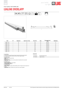


© Copyright 2026