
STEEL FRAME WALL SYSTEMS INSTALLATION GUIDE
STEEL FRAME WALL SYSTEMS
INSTALLATION GUIDE
CONTENTS
Introduction
2
Applications
2
Gyprock™ Plasterboard & Accessories
2–5
Steel Frame Components
6–7
Stud Selection Tables
8–9
Non-Fire Rated Wall Systems
Framing Requirements
10
Plasterboard Installation
11 – 15
Curved Walls
16 – 19
Perimeter Details & Attachments
20 – 25
Fire Rated Wall Systems
Framing Requirements
26
Plasterboard Installation
27 – 34
Staggered Stud Framing
35 – 37
Column Encasement
38 – 39
Perimeter Details
40 – 43
Penetrations
44 – 47
Health & Safety, Warranty
48
Contact Information
48
INTRODUCTION
Gyprock™ Steel Frame Wall Systems comprise a series of
lightweight wall assemblies prepared with zinc coated steel
frame components together with one or more layers of
Gyprock™ plasterboard fixed to one or both sides of the wall.
This guide provides detailed installation information for the
fixing of Gyprock™ plasterboard to single stud, staggered
stud, double stud and curved walls for both non-fire rated
and fire rated applications.
Frame selection and assembly guidance is also provided for
non-loadbearing applications.
For additional assistance with plasterboard fixing, contact
the CSR Gyprock office in your region.
APPLICATIONS
GYPROCK™
PLASTERBOARD
CSR Gyprock manufactures and distributes a diverse range
of plasterboard sheet products for direct fixing to framing
in non-fire rated and fire rated wall systems. All Gyprock™
Plasterboards are Manufactured to AS2588 – ‘Gypsum
Plasterboard’.
Product Manufacture
Gyprock™ plasterboard products are manufactured from
gypsum, paper and a small amount of additives. Gypsum is
a naturally occurring, non-toxic sedimentary rock. The paper
liner board used for plasterboard and cornice is made from
100% recycled newspapers and cartons and the additives
are benign materials such as starch and foam.
The energy used in the manufacture of Gyprock™ is amongst
the lowest of any building product. Emissions are limited to
water vapour and products of natural gas consumption.
Good Environmental
Choice Australia
CSRG-2011
GECA 04-2011
PANEL BOARDS
The original Gyprock EC08 ™ with reCore ™
technology was the first Australian made
plasterboard to have been Certified by Good Environmental
Choice Australia (GECA). Now Superchek™ and three boards
in the EC08™ range carry GECA certification.
This certification as a good ‘environmental choice’ means
that the product complies to the environmental and social
performance characteristics as detailed in the voluntary
environmental labeling standard - Panel Boards.
Green Building
Council of
Australia (GBCA)
The Green Building Council of Australia (GBCA) is
Australia’s leading authority on green building. The GBCA
was established in 2002 to develop a sustainable property
industry in Australia and drive the adoption of green building
practices. The GBCA promotes green building programs,
technologies, design practices and processes, and
operates Australia’s only national voluntary comprehensive
environmental rating system for buildings - Green Star.
Gyprock™ Steel Frame Wall Systems are most commonly
used in non-loadbearing, non-fire rated applications, in
commercial, industrial, institutional, domestic and high-rise
construction, or in the renovation of older buildings.
Gyprock™ Steel Frame Wall Systems are also suitable for
non-loadbearing fire rated wall construction.
Gyprock ™ Steel Frame Wall Systems can be used for
internal loadbearing applications provided the steel framing
is designed to support vertical loadings. When specifying
a loadbearing wall, ensure the system chosen has an
appropriate Fire Resistance Level (FRL).
GYPROCK™ STEEL FRAME SYSTEMS
2
Gyprock™ Plasterboard CD – Recessed Edge
Gyprock Supaceil™
Features
Features
• 1.5mm recess on face side
allows formation of shallow
channel for joint reinforcement.
• 10mm thick recessed edge
plasterboard.
• Specially formulated to span
600mm on ceilings.
• Provides smooth. even and
continuous surface once jointed.
• Manufactured with CD
technology.
• 10mm and 13mm thickness.
• Manufactured to the
requirements specified in
AS2588 : 1998 – Gypsum
Plasterboard.
• Manufactured with CD
technology.
Applications
• Interior ceilings with joists at 600mm maximum centres.
Applications
• Internal walls and ceilings.
Gyprock™ Plasterboard CD – Square Edge
Features
Gyprock Soundchek™
Features
• Manufactured with CD
technology.
• Designed to provide enhanced
acoustic resistance in wall and
ceiling systems.
Square Edge Finishing
• A machine made sheet
composed of a high density
gypsum core encased in a heavy
duty linerboard.
• The square edge allows sheets
to be butted together neatly.
• These joints may be covered
with aluminium, vinyl or timber
mouldings.
Bevelled Edge Finishing
• Long edges are recessed to
assist in producing a smooth,
even and continuous surface
once jointed.
• Edges are slightly bevelled.
• 13mm thickness.
• Edges are butted together to form a neat V-joint.
• Manufactured to the
requirements specified in
AS2588 : 1998 – Gypsum
Plasterboard.
• Joints do not need to be covered with battens or finished with compounds.
• Manufactured to the requirements specified in AS2588 : 1998 – Gypsum
Plasterboard.
Applications
Applications
• Internal walls.
• Internal walls where a higher sound rating is required.
• Usually commercial construction, especially for office partitioning.
Gyprock Aquachek™
Gyprock Impactchek™ 13
Features
Features
• 13mm thickness plasterboard
reinforced with a woven
fibreglass mesh.
• Specially processed
plasterboard.
• Both the core and linerboard
facing are treated in manufacture
to withstand the effects of
moisture and high humidity.
• High strength to resist soft body
impact damage.
• Long edges are recessed on the
face side to assist in producing
a smooth, even and continuous
surface once jointed.
• Manufactured to the
requirements specified in
American Society for Testing and
Materials C630.
• Violet coloured face linerboard
for easy identification.
• For use as a wall and ceiling
lining in ‘wet areas’ and high
moisture areas in residential and
commercial applications.
• Recessed edges allow flush
jointing to Recessed Edge
Plasterboard.
Applications
• High traffic areas such as hallways, stairways, playrooms and garages.
Applications
• Gyprock Aquachek™ is a suitable substrate for ceramic tiles.
• Usage areas include bathrooms, kitchens, laundries. garages and ceiling
applications such as walkways and verandahs.
• The Gyprock Aquachek™ Wet Area Lining System is suitable for walls in
high, medium and low risk level wet areas as defined in AS3740.
GYPROCK™ STEEL FRAME SYSTEMS
3
Gyprock EC08™ Fire
Gyprock Fyrchek™
Features
Features
• A fire rated board developed for
use in Green Star buildings.
• Suitable for wall and ceiling
systems where a fire rating is to
be achieved, or where acoustic
performance is required.
• Certified by GECA as meeting
the requirements of their
environmental standard for
Panel Boards. The basis of the
certification is Gyprock ReCore™
technology, raising the level of
recycled content.
• Composed of a specially
processed glass fibre reinforced
gypsum core encased in a heavy
duty pink liner board.
• Long edges are recessed for
flush jointing.
CSRG-2011
GECA 04-2011
PANEL BOARDS
Applications
Applications
• Fire rated walls and ceilings.
• GECA certified board with fire and acoustic rating and suited to party walls
and meeting rooms.
• High performance acoustic rated walls and ceilings.
Gyprock Fyrchek MR™
Gyprock EC08™ Impact
Features
Features
• A fire rated board with moisture
resistant properties.
• Fire and acoustic rated board
that also offers increased impact
resistance for applications in
Green Star buildings.
• Primarily intended for walls and
ceilings in ‘wet areas’ and for
protected soffits and external
eaves which must also achieve
fire resistance.
• Certified by GECA as meeting
the requirements of their
environmental standard for
Panel Boards. The basis of the
certification is Gyprock ReCore™
technology, raising the level of
recycled content.
• Both the core and the liner board
are treated in manufacture to
withstand the effects of high
humidity and moisture.
• Long edges are recessed for
flush jointing.
Applications
Applications
• Walls and ceilings in ‘wet areas’ and for protected soffits and external eaves
which must also achieve fire resistance.
Gyprock Superchek™ 10
• GECA certified board with fire and acoustic rating and increased impact
resistance for high traffic areas such as hallways and stairs in education
and health facilities.
TABLE 1: GYPROCK™ PRODUCT WEIGHTS
Features
Colour shading behind each product approximates the colour of the
product face liner sheets. For detailed sheet sizes and availability,
contact the CSR Gyprock Sales Centre in your region or refer to
www.gyprock.com.au
• 10mm plasterboard with denser
core and heavy duty facing
material.
• Resists double the force to
impose a discernable surface
indentation compared to
standard plasterboard.
• Denser core for sound
resistance. Walls lined with
Superchek™ provide a clearly
noticeable, 15% reduction in
perceived loudness compared to
standard plasterboard.
Gyprock™ Lining Products
CD RECESSED EDGE
CSRG-2011
GECA 04-2011
PANEL BOARDS
CD SQUARE EDGE
CD RECESSED EDGE/SQUARE
Applications
EDGE
SUPACEIL™
SOUNDCHEK™
• High traffic areas such as hallways, stairways, playrooms and garages.
Gyprock EC08™ Partition
AQUACHEK™
Features
IMPACTCHEK™
SUPERCHEK™
EC08™ PARTITION
EC08™ FIRE
EC08™ IMPACT
FLEXIBLE
• A general purpose non-fre rated
board developed for use in
Green Star buildings.
• Certified by GECA as meeting
the requirements of their
environmental standard for
Panel Boards. The basis of the
certification is Gyprock ReCore™
technology, raising the level of
recycled content.
CSRG-2011
GECA 04-2011
PANEL BOARDS
FYRCHEK™
CSRG-2011
GECA 04-2011
PANEL BOARDS
FYRCHEK™ MR
Applications
• An economical, non-fire rated board for general wall and ceiling use and
office fit-outs where fire and acoustic properties are not required.
Thickness
Mass
mm
kg/m2
10
13
10
13
6.5
8.5
6.5
8.5
10
6.5
10
13
10
13
13
10
13
13
13
6.5
13
16
13
7.2
13.0
8.0
10.4
10.3
10.4
9.3
10.5
12.1
4.25
10.5
12.5
10.7
16
13.5
PERFORATED SHEET
13
10.0
SHAFT LINER PANEL
25
19.8
GYPROCK™ STEEL FRAME SYSTEMS
4
TABLE 2: FIXING TO STEEL 0.5 – 0.8MM BMT
Plasterboard Thickness
1st Layer
2nd Layer
3rd Layer
1 or 2 x 6.5mm Plasterboard
#6-18 x 25mm Bugle, NP
#6-18 x 25mm Bugle, NP
–
1 or 2 x 10mm Plasterboard
#6-18 x 25mm Bugle, NP
#6-18 x 40mm Bugle, NP
–
1, 2 or 3 x 13mm Plasterboard
#6-18 x 25mm Bugle, NP
#6-18 x 40mm Bugle, NP
#10-40 Laminating
1, 2 or 3 x 16mm Plasterboard
#6-18 x 30mm Bugle, NP
#6-18 x 45mm Bugle, NP
#10-40 Laminating
13mm + 16mm Plasterboard
#6-18 x 25mm Bugle, NP
#6-18 x 45mm Bugle, NP
–
TABLE 3: FIXING TO STEEL 0.8 – 2.4MM BMT
Plasterboard Thickness
1st Layer
2nd Layer
3rd Layer
1 or 2 x 6.5mm Plasterboard
#6-18 x 25mm Bugle, DP
#6-18 x 25mm Bugle, DP
–
1 or 2 x 10mm Plasterboard
#6-18 x 25mm Bugle, DP
#6-18 x 40mm Bugle, DP
–
1, 2 or 3 x 13mm Plasterboard
#6-18 x 25mm Bugle, DP
#6-18 x 40mm Bugle, DP
#10-40 Laminating
1, 2 or 3 x 16mm Plasterboard
#6-18 x 30mm Bugle, DP
#6-18 x 45mm Bugle, DP
#10-40 Laminating
13mm + 16mm Plasterboard
#6-18 x 25mm Bugle, DP
#6-18 x 45mm Bugle, DP
–
Stud Adhesive
Jointing Compounds
Gyprock™ Acrylic Stud Adhesive is coloured blue for easy
identification. It can be used on both timber and steel in
temperatures not less than 5ºC.
CSR Gyprock has a wide range compounds, cements and
accessories for finishing plasterboard installations.
Contact surfaces must be free of oil, grease or other foreign
materials before application.
The adhesive is applied with a broad knife to form 25mm
diameter by 15mm high walnuts.
WARNING
• Stud adhesive MUST NOT be used on FIRE RATED or
TILED WALL systems.
• Daubs of adhesive must never coincide with fastener
points.
• Stud adhesive does not constitute a fixing system on its
own and it must be used in conjunction with nail or screw
fasteners.
Gyprock™ Mastics & Sealants
In fire rated systems where caulking is indicated, a fire-rated
sealant such as Gyprock™ Fire Mastic must be used. Where
specified for joints designed for significant movement, a
polyurethane sealant such as Bostik Fireban One (FB1) may
be used. Both products are also recommended for caulking
acoustic systems and are available in 600ml sausages.
Gyprock™ Wet Area Acrylic Sealant is recommended for
sealing non-fire rated wet area systems. It is available in
300ml cartridges.
Gyprock™ Cornice
Gyprock ™ Cove Cornice in 55mm and 90mm sizes is
available in all states. 75mm is available in Western Australia
and Victoria only.
Refer the Gyprock™ Plasterboard Residential Installation
Guide, NºGYP547 for details.
Jointing of Wet Areas
CSR Gyprock recommends that a Gyprock™ Wet Area Base
Coat be used at horizontal and vertical joints within wet areas
such as showers and above basins.
Where sheets are to be a substrate for tiling, set corners with
paper tape and two coats of Wet Area Base Coat. Cover all
fastener heads with Wet Area Base Coat.
Joints in non-tiled areas (that are not designated wet areas)
may be finished with Gyprock™ finishing compounds.
Handling & Storage
All materials must be kept dry, preferably stored inside. Care
should be taken to avoid sagging or damage to ends, edges
and surfaces of sheets.
All GYPROCK plasterboard must be stacked flat, properly
supported on a level platform or on support members which
extend the full width of the sheets and which are spaced at
a maximum of 600mm centres.
If stored outside, sheets must be stored off the ground,
stacked as previously detailed and protected from the
weather.
Buildings should be sealed against water ingress before
plasterboard is installed. It is recommended that plasterboard
damaged by water is rejected or replaced.
Gyprock Classic™, Concerto™ and Tempo™ Cornice are
90mm profiles, Jazz™ and Symphony™ cornice are 75mm
profiles, available in all states.
GYPROCK cornice sections are available in various lengths.
Call your local sales office for lengths stocked in your state.
It is recommended that cornice be attached with Gyprock™
Cornice Cement.
GYPROCK™ STEEL FRAME SYSTEMS
5
STEEL FRAME COMPONENTS
Component Selection
Steel Studs
CSR Gyprock recommends steel components manufactured
by Rondo Building Services Pty Ltd.
Rondo Steel Studs are manufactured with 25mm diameter
holes at regular spacings along the web to allow electrical/
plumbing services to be easily installed through framing.
Service holes in adjacent studs should be aligned at the time
of frame assembly.
Additional information on steel building components can
be obtained from the Rondo Building Services Pty Ltd,
telephone 1300-367-663.
Studs of 0.50, 0.55 and 0.75mm BMT have bell-mouthed
service holes which have no protruding sharp edges, thereby
eliminating the need to fit grommets to protect electrical
installations.
Other steel components of equivalent performance may be
used, however it is the responsibility of the manufacturer of
the steel component to substantiate equivalent performance
with the recommended component.
Studs of 1.15mm BMT have punched service holes at
regular spacings along the web.
TABLE 4: PRODUCTION SIZES FOR RONDO STEEL STUDS (mm)
Depth
BMT
2400
2700
3000
3300
3600
4200
✓
✓
✓
✓
✓
0.50*
51
✓
✓
0.75
✓
✓
✓
✓
✓
✓
0.50*
✓
✓
✓
✓
64
0.75
✓
✓
1.15
✓
✓
✓
✓
✓
✓
0.55*
✓
✓
✓
✓
76
0.75
★
★
✓
★
1.15
✓
✓
✓
✓Q
✓Q
✓Q
0.55*
✓
✓
✓
✓
✓
92
0.75
★
✓
★
1.15
✓
0.75
150
1.15
★ = Production lead time may be required Q = Rondo Quiet Stud *= Rondo Hemmed Stud
33.5
7500
✓
✓
✓
★
✓
✓
★
✓
✓
★
✓
✓
★
✓
★
✓
★
5.0
6mm
5.0
8.0
92mm
BMT
0.50/0.55
Depth
BMT
1.15
6.35
7200
45mm
8.0
Depth
Depth
8.15
BMT
0.75
6000
32.8
35.0
35.5
4800
35.4
35.0
6mm
RONDO HEMMED STUD
RONDO LIPPED STEEL STUD PROFILES
43mm
RONDO QUIET STUD
RONDO STUD CLIP Nº126
GYPROCK™ STEEL FRAME SYSTEMS
6
Track
TABLE 6: PRODUCTION SIZES FOR RONDO
DEFLECTION HEAD TRACK
Rondo Track is used at the top and bottom of wall frames to
locate the wall studs. Studs are held in the track by friction
fit to allow for movement in the structure. Track and studs
must not be fixed together in any way, and the plasterboard
must not be fixed through the track.
BMT
Depth (mm)
1.15
Length (mm)
0.7*
0.75
51
✓
–
–
3000
64
✓
–
✓
3000
76
✓
–
✓
3000
92
✓
–
✓
3000
150
–
✓
✓
3000
*= Rondo Hemmed Stud
BMT
1.15
Depth
Depth
BMT
0.50
0.70
Nogging Track
Rondo Nogging Track is designed to support the wall studs
and prevent twisting of the studs. Factory punched holes in
the web allow quick installation to the studs. Nogging track
is an alternative to conventional cut noggings. When fitted,
nogging track should be screw fixed or crimped to both
flanges of each stud.
32.0
29.0
TABLE 5: STANDARD PRODUCTION SIZES FOR
RONDO WALL STUD TRACK
Depth
(mm)
51
64
76
92
150
0.5
✓
✓
✓
✓
BMT
0.7
–
✓
✓
✓
–
–
1.15
–
✓
✓
✓
✓
Length
(mm)
3000
3000
3000
3000
3000
32.0
BMT
0.75
Depth
Deflection Head Track
Depth
Rondo Deflection Track is used at the top of wall frames
to locate the wall studs and to allow for vertical deflection
of the ceiling/soffit. Studs are held in the track by friction
and must not be fixed to the deflection track in any way.
Plasterboard must not be fixed through the track. Refer to
installation information in the ‘Wall System Detailing’ section
of this guide.
NOTE: Hemmed track leg
length = 46mm
TABLE 7: RONDO STEEL NOGGING TRACK
Stud Spacing
450mm
600mm
Track 0.75 BMT
Depth
(mm)
Length
(mm)
51
✓
✓
3600
64
✓
✓
3600
76
✓
✓
3600
92
✓
✓
3600
150
✓
✓
3600
BMT
0.75/1.15
50.0
GYPROCK™ STEEL FRAME SYSTEMS
7
STUD SELECTION TABLES
Table 8 and 11 provide stud selection information suitable for all CSR Gyprock non-fire rated and fire rated
non-loadbearing internal wall systems that are to be designed for a Uniform Distributed Load (UDL) of 0.25kPa.
Table 9 provides stud selection information suitable for specialised fire rated non-loadbearing wall systems that are required to
be designed for a UDL of 0.35kPa. Refer to Rondo for other design pressures and for loadbearing walls.
TABLE 8: MAXIMUM WALL HEIGHT WITH RONDO LIPPED STEEL STUDS – NON-LOADBEARING WALLS
– WALLS GENERALLY (LOAD = 0.25kPa)
Wall Frame and
Lining Configuration
600mm max. cts
600mm max. cts
300mm 300mm
max. cts max. cts
300mm 300mm
max. cts max. cts
Boxed
Stud Size
BMT
Linings (mm)
10
13
16
CSR 080(-/180/180)
10
13
0.5
51
0.75
0.5
64
0.75
92
0.75
1.15
150
0.75 1.15
3.93
4.22
4.35
3.60
3.13
3.25
76
1.15 0.55 0.75 1.15 0.55
Maximum Wall Height (m)
4.17 3.70 4.43 4.65 4.54
4.43 4.13 5.02 5.22 4.94
4.52 4.30 5.25 5.42 5.18
4.30 3.80 4.10 5.00 4.40
3.53 3.20 3.58 4.05 3.61
3.58 3.24 3.82 4.05 3.61
2.77
3.20
3.38
2.60
2.32
2.32
2.91
3.32
3.52
2.60
2.60
2.60
3.33
3.72
3.91
3.30
2.72
2.72
4.83
5.50
5.71
4.80
4.13
4.18
5.11
5.75
5.92
5.00
4.69
4.69
6.55
6.99
7.19
7.00
5.33
5.37
7.22
7.54
7.65
7.65
6.81
6.81
16
2.32
2.60
2.75
3.28
3.59
4.20
4.69
5.37
6.81
10
2.37
2.83
3.51
10
2.93
3.61
–
3.25
3.87
4.05
3.61
Studs
TABLE 9: MAXIMUM WALL HEIGHT WITH RONDO LIPPED STEEL STUDS – NON-LOADBEARING WALLS
– WALLS OF SHAFTS AND FIRE ISOLATED EXITS (LOAD = 0.35kPa)
Wall Frame and
Lining Configuration
600mm max. cts
600mm max. cts
300mm 300mm
max. cts max. cts
300mm 300mm
max. cts max. cts
Boxed
Stud Size
BMT
Linings (mm)
0.5
51
0.75
0.5
64
0.75
76
1.15 0.55 0.75 1.15 0.55
Maximum Wall Height (m)
92
0.75
1.15
150
0.75 1.15
10
2.42
2.55
2.93
3.49
3.70
3.25
3.81
3.81
3.81
3.81
3.81
3.81
3.81
13
2.81
2.92
3.29
3.75
3.94
3.65
4.43
4.60
4.39
4.84
5.06
5.71
5.71
16
3.00
3.12
3.45
3.84
3.99
3.78
4.62
4.77
4.60
5.01
5.20
6.37
6.89
CSR 080(-/180/180)
2.60
2.60
3.30
3.60
4.30
3.78
4.10
4.77
4.40
4.80
5.00
6.37
6.89
10
2.07
2.34
2.34
2.80
3.15
2.76
3.20
3.62
3.06
3.70
3.81
3.81
3.81
13
2.07
2.34
2.34
2.80
3.17
2.76
3.37
3.62
3.06
3.70
4.20
4.83
5.53
16
2.07
2.34
2.34
2.90
3.18
2.76
3.41
3.62
3.06
3.70
4.20
4.83
5.53
10
2.14
2.59
3.15
10
2.65
3.26
–
Studs
NOTES:
Deflection Limit is span/240 to a maximum of 30mm, in accordance
with BCA Specification C1.8.
Tabulated heights do not include axial loads (except self weight) or
shelf loading.
Loadings: Table 8 Pultimate = 0.375 kPa, Pservice = 0.25 kPa.
Loadings: Table 9 Pultimate = 0.525 kPa, Pservice = 0.35 kPa.
Walls are not for external applications.
All loadings in accordance with AS1170:2002.
Walls analysed in accordance with AS4600:1996.
Noggings in accordance with Table 10.
Staggered stud walls use 64mm lipped studs in 92mm track with
Gyprock™ Staggered Stud Clip.
Tables have been prepared by Rondo Building Services Pty Ltd.
TABLE 10: MINIMUM NUMBER OF NOGGINGS
Lining Configuration
Wall Height (m)
Number of Noggings
Lined Both Sides
0 - 4.4
4.4 - 8.8
0.0 - 3.0
3.0 - 6.0
6.0 - 8.0
All
equally spaced
0
1
1
2
3
0
Lined One Side*
Staggered Studs
NOTES: *Plus noggings at head. Refer to details.
GYPROCK™ STEEL FRAME SYSTEMS
8
TABLE 11: MAXIMUM WALL HEIGHT FOR RONDO QUIET STUD – WALLS GENERALLY ( LOAD 0.25kPa)
Wall frame and lining configuration
Spacing
Minimum Plasterboard
Stud Spacing
Thickness
600
450
10
3.70
4.02
13
4.13
4.41
16
4.30
4.58
GYPROCK™ STEEL FRAME SYSTEMS
9
NON-FIRE RATED
FRAMING
REQUIREMENTS
Nogging
Introduction
Nogging is required in non-loadbearing double stud walls
and single stud walls lined on one side only. An additional
nogging is required near the top of the wall. Refer to Wall
Head Details.
Nogging is not required in non-loadbearing single stud
wall systems less than 4400mm in height which have
plasterboard fixed on both sides.
Non-loadbearing wall framing is constructed using Rondo
lipped steel studs fitted into track sections positioned at the
top and bottom of the wall.
Deflection head track must be used on all walls exceeding
4800mm in height and may be specified in any wall system
to allow for vertical movement of the roof/ceiling.
Studs are held in the tracks by friction fit, and they must not
be fixed together by mechanical fasteners or crimping except
where specifically required around door openings.
Staggered stud wall systems are constructed using the
Gyprock Staggered Stud Clip to locate 64mm depth lipped
studs in 92mm floor and ceiling tracks. Alternatively, Rondo
P140 sections may be used to locate studs to head track/
angles. Refer to detailed assembly information.
CSR Gyprock recommends that internal non-loadbearing,
non-fire rated walls be designed for a minimum UDL of
0.25kPa. Refer to Tables 8 to 11 for suitable stud sizes/
height selection information. Where higher pressures are
specified, contact Rondo Building Services.
Control Joints
Control joints must be provided through the frame and
wall lining at 12m maximum centres and to coincide with
building control joints, at changes to framing material, and
at junctions with other walls. Control joints are formed using
two studs.
Where nogging is required, it should be screw fixed or
crimped to both flanges of each stud.
Noggings must be installed where support is required for
attaching handrails and wall fixtures.
Nogging must not be installed in staggered stud wall
systems, as additional connection between studs reduces
the acoustic performance of these wall systems.
Nogging must be installed in loadbearing wall systems to
stabilise the wall. Refer to your project engineer or Rondo
Building Services for requirements.
Installation Procedure
Single and Double Stud
• Accurately align floor and ceiling tracks according to the wall
layout and fasten in place at 100mm maximum from each end
of the track and at 600mm maximum centres along the track.
Apply a continuous bead of sealant between the track and
support structure where acoustic integrity is required.
• Place studs into the tracks and twist into position. The
track flanges should provide a friction fit. Ensure studs are
bottomed in floor track. Do not fix studs to top and bottom
tracks.
FIG 1: STUD INSTALLATION
Track Fixings
Each track fastener is required to withstand a shear load of
0.75kN for walls with a design load of 0.25kPa.
For walls with a design UDL of 0.35kPa, each track fastener
is required to withstand a sheer load of 1.1kN.
When fixing to concrete or masonry, use power driven
fasteners, expansion anchors (eg. Dynabolts™), or easy drive
masonry anchors.
When fixing to suspended ceiling systems, use
CSR Gyprock™ Type ‘S’ Screws, toggle bolts or expandable
fasteners.
• Position a stud at each end of the wall, and where
appropriate, fix its web to the adjacent wall structure.
• Position studs along the wall at 600mm maximum centres.
The open sides of these studs should be facing the end
of the wall from which sheeting will begin.
• Where nogging track is to be used, fit to studs before
installing into tracks. Otherwise cut-to-length nogging can
be fitted after stud installation.
GYPROCK™ STEEL FRAME SYSTEMS
10
NON-FIRE RATED
Caulking
PLASTERBOARD
INSTALLATION
Caulk all perimeter gaps and penetrations to achieve stated
acoustic performance. Use Gyprock ™ Wet Area Acrylic
Sealant or Gyprock™ Fire Mastic.
Introduction
Gyprock™ plasterboard sheets may be installed horizontally
or vertically.
Vertical installation is generally preferred for commercial
steel frame installations. However to achieve some ‘Levels
of Finish’, or in areas of glancing or critical lighting, horizontal
sheeting may be used.
Fixing Notes
• Walls that are to be tiled must be fastener fixed. Adhesive
is not permitted.
• Adhesive daubs must never coincide with fastening
points.
• Do not fasten plasterboard sheeting to head tracks.
• Do not fix plasterboard to steel framing which is greater
than 2.0mm in thickness.
• Sheet joints are not to coincide with edges of openings.
Refer to FIG 2.
• Sheets are to be held firmly against frame while fasteners
are positioned. Wherever possible commence fastening
from the centre portion of the sheet, proceeding to the
ends and edges. Alternatively, start at one edge and work
across the sheet to the other edge.
• Fasteners are to be driven home with the head slightly
below the surface of the sheet, but not punched through
the face linerboard. Best results are obtained using a
screw gun. Care should be taken to avoid damaging the
face or core of the plasterboard.
Jointing & Finishing
For jointing and finishing information, refer to the Gyprock™
Residential Installation Guide, NºGYP547. In multi-layer
systems, jointing and finishing is required on the outer layer
only, on each side of the wall.
Tiling
Where Gyprock ™ plasterboard is used as a substrate
for tiles, the sheets must be fastened with screws only.
Adhesive/fastener fixing is not acceptable.
Where tiles will be up to 12.5kg/m2, space screws in the field
of the sheet at a maximum 200mm centres. Internal corners,
external corners, around openings and butt joints are to
be fastened at a maximum 150mm centres, with fasteners
opposite each other at all joints. Where wall tiles are up to
32kg/m2, space screws at 100mm maximum centres to the
field of the board, internal corners, external corners, around
openings and butt joints.
Fixing Procedures
Where possible, sheeting should commence from the end
facing the open side of the studs. Refer to illustrations.
FIG 3: SHEETING DIRECTION AND RECESS JOINT
LOCATION FOR VERTICAL SHEETING
First Side – Full Width Sheet
locates on second stud
1
• Ensure that all services and insulation materials are
installed (when required), prior to the fixing of sheets to
the second side of the wall.
2
3
200mm
min.
Sheet
joints
200mm
min.
4
Second Side – Cut Width Sheet
locates on first stud
FIG 2: JOINT LAYOUT FOR VERTICAL OR HORIZONTAL
SHEETING
Direction of sheeting
Control
joint
FIG 4: SHEETING DIRECTION AND BUTT JOINT
LOCATION FOR HORIZONTAL SHEETING.
Butt Joints offset
between layers
5
6
2
1
3
7
4
Butt Joints offset on
opposite sides of the wall
Direction of sheeting
GYPROCK™ STEEL FRAME SYSTEMS
11
8
NON-FIRE RATED
FIG 5: PLASTERBOARD FIXING DETAIL – VERTICAL SHEETING – ADHESIVE/FASTENER FIXING
Fixing Specifications
Screws
Adhesive
Location
Fixing & Spacing
Field
Adhesive Daubs at
300mm max. centres
and 200mm min.
from fastener points
Screw at top and
bottom and 1200mm
max. cts
Recessed
Edges
Screw at top and
bottom and 400mm
max. cts
Corners &
Openings
Screws at
300mm max. centres
300mm
max.
400mm
max.
300mm
max.
Refer to Table 2 & 3
Gyprock Stud
Adhesive
200mm
min.
CSR Bradford Acoustic
Insulation if required
Screw at
1200mm
max.
vertical
centres
SUITABLE FOR:
Daubs of CSR Gyprock®
Acrylic Stud Adhesive
One layer of Gyprock®
plasterboard to each side
of wall
300mm
max.
Refer to perimeter details
200mm
min.
Noggings may not be permitted
in staggered stud systems
Notes On Fixing
• Offset joints on opposite sides of the wall by one stud.
• Cut sheets as necessary to provide up to 10mm gap at
the bottom and appropriate clearance at the top.
• Press the sheet firmly against the studs and screw fix
recessed edges to the studs at 100mm maximum from
top and bottom of sheet (but not through tracks) and at
400mm maximum centres.
• Do not fix sheets to the top and bottom tracks, (fix to
studs only).
• Screw fix to intermediate stud at 100mm maximum from
top and bottom of sheet (but not through tracks) and at
1200mm maximum vertical centres.
• Daubs of adhesive must be 200mm minimum from
fastening points.
• Screw fix at all corners and around openings at 300mm
maximum centres.
• Place edge fasteners at 10 to 16mm from sheet edge.
Second Side
• Where possible, sheeting should commence from the end
facing the open side of the studs.
• Ensure all electrical/plumbing/insulation materials have
been installed before sheeting second side.
Fixing Procedure
• Cut the first sheet so that joints on opposite sides of the
wall are located on different studs.
For fastener specifications refer to Table 2 & 3.
• Screw fix this sheet to both studs at 300mm maximum
centres.
First Side
• Apply stud adhesive to intermediate studs. Using a
broadknife apply daubs 25mm diameter x 15mm high at
200mm minimum from fastening points and at 300mm
maximum centres.
• Adhesive and fastener fix subsequent sheets as per
instructions for the first side.
• Apply sheets vertically (paper bound edges parallel with
studs), leaving a 10mm max. gap between the bottom of
the sheet and the floor, and with recess joints centred on
stud flanges.
GYPROCK™ STEEL FRAME SYSTEMS
12
NON-FIRE RATED
FIG 6: PLASTERBOARD FIXING – HORIZONTAL SHEETING – ADHESIVE/FASTENER FIXING
Fixing Specifications
For Level 4 finish, form butt
joints between framing
Screw
along sheet
centreline
at every
second
stud
300mm
max.
Screws
Adhesive
Refer to Table 2 & 3
Gyprock Stud
Adhesive
Location
Fixing & Spacing
Field
Sheet
Width
900mm
1200mm
1350mm
Adhesive Daubs at
300mm max. centres
and 200mm min.
from fastener points
3 daubs
4 daubs
5 daubs
Screw at every
second stud along
sheet centreline
Recessed
Edges
Screw at each stud
Butt joints
Screws at 200mm
centres
Corners &
Openings
Screws at 300mm
max. centres
200mm
min.
One layer of Gyprock®
plasterboard to each side
of wall
SUITABLE FOR:
Daubs of CSR Gyprock®
Acrylic Stud Adhesive
200mm
max.
300mm
max.
300mm
max.
CSR Bradford Acoustic
Insulation if required
200mm
min.
Refer to perimeter details
Noggings may not be permitted
in staggered stud systems
Notes On Fixing
• Butt joints in adjacent sheets and on opposite sides of the
wall must be staggered by a minimum of one stud spacing
• For a level 4 finish, butt joints must be formed between
studs
• Do not fix sheets to the top and bottom tracks, (fix to
studs only).
• Daubs of adhesive must be 200mm minimum from
fastening points.
• Place edge fasteners at 10 to 16mm from sheet edge.
• Where possible, sheeting should commence from the end
facing the open side of the studs.
Fixing Procedure
• Screw fix to each stud along one recessed edge,
beginning at the centre of the sheet and working towards
the ends.
• Press the sheet firmly against the studs and screw fix to
each stud along the second recessed edge. Do not fix
through top and bottom tracks.
• Hold the sheet firmly against the studs, and screw fix
along the centreline of the sheet at every second stud.
• Screw fix butt joints at 200mm maximum centres.
• Screw fix at all corners and around openings at 300mm
maximum centres.
• Apply the next row of sheets, cutting the first sheet so
that butt joints will be offset from adjacent sheets by a
minimum of one stud.
For fastener specifications refer to Table 2 & 3.
• Cut sheets as necessary to ensure appropriate clearance
is provided at the head.
First Side
Second Side
• Apply stud adhesive to intermediate studs. Using a
broadknife apply daubs 25mm diameter x 15mm high at
200mm minimum from fastening points and at 300mm
maximum centres.
• Ensure all electrical/plumbing/insulation materials have
been installed before sheeting second side.
• Apply sheets horizontally (paper bound edges at right
angles to studs), leaving a 10mm max. gap between the
bottom of the sheet and the floor, and with butt joints
centred on stud flanges.
• Cut sheets as necessary so that butt joints in adjacent
sheets and on opposite sides of the wall are staggered
on different studs.
• Apply and fix sheets as detailed for the first side.
GYPROCK™ STEEL FRAME SYSTEMS
13
NON-FIRE RATED
FIG 7: FASTENER FIXING – SINGLE LAYER HORIZONTAL SHEETING – NON-TILED AREAS
Fixing Specifications
For Level 4 finish, form butt
joints between framing
400mm
max.
300mm
max.
®
One layer of Gyprock
plasterboard to each side
of wall
Screws
Refer to Table 2 & 3
Location
Fixing & Spacing
Field
Screws at 400mm
max. centres
Sheet
Width
900mm
1200mm
1350mm
4 Screws
4 Screws
5 Screws
Recessed
Edges
Screw at each stud
Butt joints
Screws at 200mm
max. centres
Corners &
Openings
Screws at 300mm
max. centres
SUITABLE FOR:
200mm
max.
CSR Bradford Acoustic
Insulation if required
Refer to perimeter
details
Noggings may not be permitted
in staggered stud systems
Notes On Fixing
• Butt joints in adjacent sheets and on opposite sides of the
wall must be staggered by a minimum of one stud spacing
• Screw fix at all corners and around openings at 300mm
maximum centres.
• For a level 4 finish, butt joints must be formed between
studs
• Apply the next row of sheets, cutting the first sheet so
that butt joints will be offset from adjacent sheets by a
minimum of one stud spacing.
• Do not fix sheets to the top and bottom tracks, (fix to
studs only).
• Cut sheets as necessary to ensure appropriate clearance
is provided at the head.
• Place edge fasteners at 10 to 16mm from sheet edge.
Second Side
• To avoid stud distortion, sheeting should commence from
the end facing the open side of the studs.
• Ensure all electrical/plumbing/insulation materials have
been installed before sheeting second side.
Fixing Procedure
• Cut sheets as necessary so that butt joints in adjacent
sheets and on opposite sides of the wall are staggered
on different studs.
For fastener specifications refer to Table 2 & 3.
• Apply and fix sheets as detailed for the first side.
First Side
• Apply sheets horizontally (paper bound edges at right
angles to studs), leaving a 10mm max. gap between the
bottom of the sheet and the floor where an acoustic seal
is required
• Screw fix to each stud, beginning at the centre of the sheet
and working towards the ends and edges. Alternatively,
start at one edge and work across the sheet to the other
edge.
• Screws are to be spaced at 400mm maximum centres
along studs. Do not fix through top and bottom tracks.
• Where butt joints on framing are permitted, screw fix butt
joints at 200mm maximum centres.
GYPROCK™ STEEL FRAME SYSTEMS
14
NON-FIRE RATED
FIG 8: PLASTERBOARD FIXING – TWO LAYER – VERTICAL SHEETING – ADHESIVE/FASTENER FIXING
Fixing Specifications
200mm
max.
300mm
max.
Two layers of Gyprock®
plasterboard to each side
of wall
400mm
max.
200mm
min.
CSR Bradford Acoustic
Insulation if required
Screw at
1200mm
max.
vertical
centres
400mm
max.
Daubs of CSR Gyprock®
Acrylic Stud Adhesive
Screws
Adhesive
Refer to Table 2 & 3
Gyprock Stud
Adhesive
1st Layer
Fixing & Spacing
Recessed
Edges &
Field
Screws at top and
bottom and at
400mm max. centres
2nd Layer
Fixing & Spacing
Field
Adhesive Daubs at
300mm max. centres
and 200mm min.
from fastener points.
Screw at top and
bottom and 1200mm
max.cts
Recessed
Edges
Screw at top and
bottom and 400mm
max. cts
Corners &
Openings
Screws at 300mm
max. centres
SUITABLE FOR:
300mm
max.
400mm
max.
Refer to perimeter details
Noggings may not be permitted
in staggered stud systems
Notes On Fixing
Second Side – First Layer
• First layer is installed vertically and fully screw fixed (no
adhesive). Second layer is fixed with adhesive and screws,
and sheets may be installed vertically or horizontally. Refer
to FIG 7 for horizontal fixing.
• Ensure all electrical/plumbing/insulation materials have
been installed before sheeting second side.
• Cut sheets as necessary to provide up to 10mm gap at
the bottom of outer sheets, and an appropriate clearance
at the top.
• Screw fix this and subsequent full width sheets as detailed
for the first side.
• Daubs of adhesive must be 200mm minimum from
fastening points.
• Place edge fasteners at 10 to 16mm from sheet edge.
• Where possible, sheeting should commence from the end
facing the open side of the studs.
Fixing Procedure
For fastener specifications refer to Table 2 & 3.
First Side – First Layer
• Apply sheets vertically (paper bound edges parallel with
studs), with the bottom edge of the sheet on the floor, and
with recess joints centred on stud flanges.
• Press the sheet firmly against the studs and screw fix to
at top and bottom (but not through tracks) and at 400mm
maximum centres along all studs.
• Screw fix at all corners and around openings at 300mm
maximum centres.
• Cut the first sheet so that joints on opposite sides of the
wall are located on different studs.
First Side – Second Layer
• Cut the first sheet so that joints in the second layer do not
align with joints in the first layer.
• Apply sheet vertically, leaving a 10mm max. gap between
the bottom of the sheet and the floor, and screw fix at top
and bottom (but not through tracks) and at 400mm max.
centres to both studs.
• Apply stud adhesive over intermediate studs. Using a
broadknife apply daubs 25mm diameter x 15mm high at
200mm minimum from fastening points and at 300mm
maximum centres.
• Continue applying full sheets vertically with recess joints
centred over stud flanges.
• Press sheets firmly against the studs and screw fix
recessed edges at top and bottom (but not through
tracks) and at 400mm max. centres.
• Press sheets firmly against the studs and screw fix to
intermediate stud at top and bottom (but not through
tracks) and at 1200mm maximum vertical centres.
• Screw fix at all corners and around openings at 300mm
maximum centres.
GYPROCK™ STEEL FRAME SYSTEMS
15
NON-FIRE RATED
CURVED WALLS
Applications
Framing Preparation
GYPROCK plasterboards of 10mm or greater thickness may
be used on curved walls where the radius of the curve is
900mm or greater, as detailed in Table 12.
Prepare the curved framing in accordance with Table 12 or
13 and FIG 9 appropriate for the chosen plasterboard and
curving radius. For small radius curves, install double studs
at each end of the curve to prevent frame deflection.
Fire rated walls MUST NOT be curved to a radius of less
than 3000mm.
Where a radius tighter than 900mm is to be used, the wall
should be sheeted with GYPROCK Flexible Plasterboard.
Rondo Flexi-Track™ makes the job of preparing curved walls
considerably easier, and is available in 0.55 BMT for general
use, and in 0.75 BMT for deflection head applications.
Flexi-Track™ should be fixed at each stud, through the prepunched holes provided.
Gyprock™ Flexible Plasterboard
CSR Gyprock™ Flexible Plasterboard has been specifically
designed for curved wall applications. It is particularly
effective for small radius situations (less than 900mm) which
can not be accomplished with 10 or 13mm GYPROCK
plasterboards.
Refer to Table 13 for the minimum curving radius and
maximum stud spacing for Gyprock™ Flexible Plasterboard
applications.
Ensure that all framing members to receive sheeting are
correctly spaced and aligned for the application.
Plasterboard Fixing
GYPROCK 10, 13 and 16mm plasterboards may be attached
vertically or horizontally, depending upon the framing support
and application, however, wherever possible sheets should
be installed with horizontal recess joints as this considerably
improves the ease of jointing.
Sheets should begin and end a minimum of one stud from
the curved section, and more if possible.
FIG 9: FRAMING PREPARATION FOR CURVED WALL
USING RONDO FLEXI-TRACK
See Table 12 and
13 for maximum
stud spacing
Curved walls must be screw fixed to all studs at 100mm
maximum from the top and bottom of the wall (but not
through tracks) and at (400mm maximum centres for non-fire
rated walls) or (300mm maximum centres for fire rated walls).
All vertical butt joints must fall on framing members, be screw
fixed at 200mm maximum centres, and be staggered by a
minimum of 600mm between adjacent sheets.
Minimum curving radius for
Rondo Flexi-Track™
Track Depth
Minimum
Radius
51mm
180mm
64mm
200mm
76mm
230mm
92mm
285mm
150mm
475mm
Rondo Flexi-Track®
TABLE 12: CURVING RADII AND MAXIMUM STUD SPACING FOR 6.5, 10, 13 AND 16MM GYPROCK PLASTERBOARDS
Gyprock™
Plasterboard
Flexible
Thickness
Plasterboard
(mm)
6.5
10
13
16
<900
–
–
–
All Gyprock™ Plasterboards
Gyprock™ Plasterboard CD and Flexible Plasterboard ONLY
900 – 1000
refer table 14
150
–
–
1000 – 1500
200
200
150
–
Curve Radius (mm)
1500 – 2000
2000 – 2500
Maximum Stud Spacing (mm)
250
300
250
300
200
250
–
–
GYPROCK™ STEEL FRAME SYSTEMS
16
(excluding Perforated)
2500 – 3000
3000 – 4000
4000 – Plus
350
350
300
–
450
400
400
250
450
500
500
350
NON-FIRE RATED
Flexible Plasterboard Fixing
Surface Decoration
GYPROCK Flexible Plasterboard sheets can be curved with
the recess edges bent around the curve (horizontal sheeting),
however for very small radius applications GYPROCK Flexible
Plasterboard curves significantly better where the recess
edges are not bent around the curve (vertical sheeting).
GYPROCK Flexible Plasterboard can be painted with the full
range of finishes.
The use of a preparatory sealer over the entire surface is
recommended prior to application of finish coats.
In most instances, two layers of GYPROCK Flexible
Plasterboard are recommended, and they can easily be
flush jointed to one layer of 13mm GYPROCK for adjacent
straight sections where appropriate.
All butt joints must fall on framing members.
When planning the sheet layout, ensure that the sheet edges
of the first and second layers are staggered at least 200mm
to avoid aligned joints.
Fasten GYPROCK Flexible Plasterboard as per FIG: 10, 11,
12 or 13, appropriate to the installation. Carefully follow the
screw spacing details for each application.
Wetting Flexible Plasterboard
Wetting plasterboard is usually not a recommended practice,
however when conditions of low humidity and temperatures
occur, or an extremely tight radius is to be attempted, it may
be necessary to roll on a small amount of water with a clean
paint roller.
Only wet the surface of the plasterboard that will be in
compression.
Allow 15 minutes for water to soak into the core before
attempting to bend the board.
Plasterboard Jointing & Finishing
Jointing and finishing of curved walls is in accordance with
normal practice.
In multi-layer systems, jointing and finishing is required on
the outer layer only, on each side of the wall.
Note: Under some lighting conditions, glancing light may
highlight the plasterboard joints. This is more apparent with
vertical sheeting. A skim coat to the entire plasterboard
surface is recommended to reduce this effect.
Refer to the Gyprock ™ Residential Installation Guide,
NºGYP547 for detailed jointing and finishing information.
TABLE 13: MINIMUM CURVING RADII AND MAXIMUM FRAME SPACING FOR GYPROCK FLEXIBLE PLASTERBOARD
Applications
Sheets Installed Vertically
Sheets Installed Horizontally
Minimum Radius
Max. Stud Spacing
Minimum Radius
Max stud Spacing
Concave
450mm
150mm
650mm
200mm
Convex
250mm
125mm
450mm
200mm
Notes – Low temperature and humidity will reduce board flexibility.
GYPROCK™ STEEL FRAME SYSTEMS
17
NON-FIRE RATED
Flexible Plasterboard
Fixing For Concave
Curves
FIG 10: CONCAVE – VERTICAL SHEETING
For small radius curves, install double studs to
prevent frame deflection
No curve in
this area
No curve in
this area
Apply pressure to the unrestrained
end/edge of the sheet until it comes
into contact with framing members or
substrate.
Concave Curved Area
450mm
minimum
radius
Recessed
edge of
first layer
When the sheet makes contact with
the substrate it should be fixed with the
appropriate fasteners, beginning at the
stopped end and proceeding towards the
unrestrained end/edge.
Fasten both layers at
max. 100mm centres
at first frames outside
curved area
The second layer joints should be
staggered at least 200mm from the first
layer to prevent aligned joints.
Recessed edge of
second layer
Fasten both layers at top
and bottom of sheets on
all frame members
10
0m
m
m
m
00
1
First layer and second layer
staggered a minimum 200mm
to prevent aligned joints
Sheet bottom
edge 6mm above
finished floor level
Use stopping
at edge of
sheet where
possible
FIG 11: CONCAVE – HORIZONTAL SHEETING
For small radius curves, install double studs
to prevent frame deflection
No curve in
this area
No curve in
this area
Concave Curved Area
650mm minimum radius
Use stopping at
edge of sheet
where possible
Fasten both layers at
max. 100mm centres at
first frame outside
curved area
Fasten both layers at
max. 100mm centres at
first frame outside
curved area
First layer and second layer
staggered a minimum 200mm
to prevent aligned joints
Use stopping at
edge of sheet
where possible
Recessed edge
of first layer
Recessed edge
of second layer
10
0m
mm
m
0
10
Fasten both layers at top
and bottom of each sheet
but not through tracks
Sheet bottom
edge 6mm above
finished floor level
GYPROCK™ STEEL FRAME SYSTEMS
18
NON-FIRE RATED
Flexible
Plasterboard Fixing
for Convex Curves
FIG 12: CONVEX – VERTICAL SHEETING
Fasten both layers at max.
100mm centres at start and
finish of curve and at min.
200mm from edge of curve
Attach one end/edge of the sheet to
the framing members or substrate
by fastening at the appropriate
centres.
Fasten both layers at max.
100mm centres at start and
finish of curve and at min.
200mm from edge of curve
Recessed
edge of
first layer
Convex Curved Area
250mm minimum radius
Beginning from the attached end/
edge, progressively work the sheet
against the framing.
As the sheet makes contact with
the framing, fix the sheet with the
appropriate fasteners.
The second layer joints should be
staggered at least 200mm from the
first layer to prevent aligned joints.
First layer and second layer
staggered a minimum 200mm
to prevent aligned joints
Recessed
edge of
second
layer
Avoid placing more screws than
recommended into the plasterboard
face within the curved area.
m
0m
10
10
0m
m
Sheet
bottom
edge 6mm
above
finished
floor level
Fasten both layers at top
and bottom of sheets but
not through tracks
N
in o cu
thi rve
sa
rea
rve
cu rea
No this a
in
For small radius curves, install
double studs to prevent frame
deflection
FIG 13: CONVEX – HORIZONTAL SHEETING
Fasten both layers at max.
100mm centres at start and
finish of curve and at min.
200mm from edge of curve
Fasten both layers at max.
100mm centres at start and
finish of curve and at min.
200mm from edge of curve
Convex Curved Area
450mm minimum radius
For small radius curves, install
double studs to prevent frame
deflection
Fasten both layers at top
and bottom of each sheet
m
0m
10
m
0m
Recessed edge of second layer
10
10
0m
m
Recessed edge
of first layer
No
First layer and second layer
staggered a minimum 200mm
to prevent aligned joints
cu
rve
in
thi
a
his
sa
rea
No
Sheet bottom
edge 6mm above
finished floor level
rve
t
in
are
cu
Recessed edge
of second layer
GYPROCK™ STEEL FRAME SYSTEMS
19
NON-FIRE RATED
WALL PERIMETER DETAILS
Note: Wall/ceiling junction details require engineer’s approval where seismic loads apply.
Wall Head Details
FIG 14: FRICTION FIT HEAD
FIG 17: HEAD FOR SUSPENDED TEE-LOCK CEILING
Fix track at each
main runner
Main Runner
6 – 10mm
clearance to
GYPROCK
plasterboard
100mm max.
to first fastener
(Do not fix
through track)
NOTE: Junction may be
finished square, with
stopping bead or with
cornice. Do not rigidly
fix cornice to walls
where friction joints are
used
Stud
6mm
clear
of
soffit
RONDO P50 or P60
Shadowline Stopping
Bead (finish as
required)
Fill gap with CSR
Gyprock® Wet Area
Acrylic Sealant for
acoustic integrity
Track section with
32mm flange fastened
to soffit at 600mm
centres max.
FIG 15: DEFLECTION HEAD
Fix wall sheets at 10
to15mm below head
track flanges
Stud
FIG 18: HEAD FOR SUSPENDED CEILING
Additional Furring Channel
where wall runs parallel to
setout
Fill gap with CSR
Gyprock® Wet Area
Acrylic Sealant for
acoustic integrity
Stud
Deflection Head Track
fastened at 600mm
centres max.
Furring Channel in
normal setout position
Finish as required
Fix Head Track to Furring
Channel at 600mm max.
centres
Fix wall sheets at 10
to15mm below head
track flanges
Stud
FIG 16: HEAD USING ALUMINIUM HEAD TRACK
Furring
Channel
Suspended Ceiling
Top Cross Rail
20mm clearance
to stud and
GYPROCK
plasterboard
100mm max.
to first fastener
(Do not fix through
track)
NOTE: Stopping bead
or cornice finish as
required. Do not rigidly
fix cornice to walls
where friction joints are
used
NOTE: This method of
construction is not
recommended for studs
adjacent to windows or
doors or studs carrying
loads greater than
0.25kPa.
Fix extruded track at
each furring channel
GYPROCK plasterboard
ceiling fixed to furring
channel at appropriate
centres
RONDO extruded
aluminium track for
64, 76 or 92mm
studs
Stud
GYPROCK™ STEEL FRAME SYSTEMS
20
Where wall runs
perpendicular to furring
channel fix track to furring
at each intersection
NON-FIRE RATED
FIG 19: WALL/CEILING JUNCTION – PLASTERBOARD
LINING
System insulation
Tape and
set or
cornice
finish
FIG 20: WALL/CEILING JUNCTION – PLASTERBOARD
LINING
100mm
min
System insulation
Fix wall track to ceiling
frame with Rondo 704
Partition Clip
System
insulation
Ceiling framing
GYPROCK
plasterboard
ceiling system
continuous
over wall
FIG 22: WALL/CEILING JUNCTION –
PANEL LINING
System insulation
GYPROCK
plasterboard
ceiling
Tape and set or
cornice finish
FIG 21: WALL/CEILING JUNCTION – PLASTERBOARD
LINING
GYPROCK
plasterboard ceiling
system
Rondo DUO Two-way
Steel Grid Ceiling
System
Steel angle to
support ceiling grid
100mm
min
System insulation
GYPROCK Panel
Ceiling System
FIG 24: WALL/CEILING JUNCTION –
PANEL LINING
Floor or roof structure
System insulation
Continuous bead of
CSR Gyprock
Sealant or a closed
cell foam tape
above wall track
FIG 23: WALL/CEILING JUNCTION –
PANEL LINING
System insulation
Ceiling Framing
Finish Bead as
required
GYPROCK Panel
Ceiling System
continuous over
wall in Rondo
DUO Two-way
Steel Grid
Floor or roof structure
System insulation
Tape and set or
cornice finish or
shadowline bead
System insulation
GYPROCK panel
ceiling system
GYPROCK™ STEEL FRAME SYSTEMS
21
System insulation
NON-FIRE RATED
Wall Base Details
Wall Junctions
Note: Wall/ceiling junction details require engineer’s approval
where seismic loads apply.
FIG 28: CONTROL JOINT AT JUNCTION OF MASONRY
AND STEEL STUD WALL
For additional junction details refer to the fire rated section.
Fill gap with CSR
Gyprock® Flexible
sealant for acoustic
integrity
FIG 25: WALL BASE DETAIL
RONDO Stopping
Bead and set over
Fix track at 600mm max.
centres. With 150mm width
track, use 2 fixings
approximately 20mm in
from each side of track
Stud
Do not fix
plasterboard
to end stud
Track
GYPROCK
plasterboard
Studs bottomed
in track
Fill gap with CSR Gyprock®
Sealant for acoustic
integrity
10mm
10mm max. gap
at bottom of sheet
100 to 150mm
FIG 29: CORNER DETAIL –
PLASTERBOARD TO PLASTERBOARD WALLS
FIG 26: TRACK FIXING DETAIL
Set corner
with external
angle bead
and cement
Track
Screw fix studs
at 600mm max.
vertical centres
100mm max.
to first track
fixing
mm
600
tres
cen
res
ent
x. c
a
mm
x.
ma
GYPROCK
plasterboard
Fix at 600mm
max. centres
along track
m
600
Set corner with
paper tape and
cement
Track
100mm max. from
fastener to end of track
Steel track
fixings
FIG 30: JUNCTION DETAIL –
PLASTERBOARD/PLASTERBOARD WALLS
Control Joints
Stud at wall
intersection
FIG 27: CONTROL JOINT
Fix studs at 600mm
max. vertical centres
(Maintains acoustic integrity of the wall system in which it is installed).
For Rw up to 40, use backing rod only detail.
For Rw greater than 40, use backing rod and sealant detail.
Track fixing 100mm
max. from wall
intersection
Track
Finish surface
as per external angles
RONDO P35
Control Joint
15-20mm
gap
Additional stud to
form control joint
Stud in
normal
position
Set corners with
paper tape and
cement
100mm max.
to first track
fixing
GYPROCK
Plasterboard
RONDO P35
Control Joint
Finish surface
as per external angles
CSR Gyprock® Flexible
Sealant (depth equal to
wall lining thickness) for
acoustic integrity
15-20mm
gap
Backing Rod
– non fire rated
22mm dia. for
acoustic integrity
GYPROCK
plasterboard
Fix at 600mm
max. centres
along track
GYPROCK™ STEEL FRAME SYSTEMS
Track
Metal track
fixings
22
NON-FIRE RATED
Wet Area Details
IMPORTANT: Refer to the Components section for requirements on Wet Area Jointing.
FIG 31: INSITU-FORMED SHOWER RECESS
CERAMIC TILED
FIG 33: BATH INSTALLATION
Steel
Stud
GYPROCK
AQUACHEK
GYPROCK AQUACHEK
Vertical Corner
Angle Flashing
Steel
Stud
Ceramic Tiles
Ceramic Tiles
RONDO
Nº255 Top
Hat Section
to support
bath
Waterproof Membrane
to face of plasterboard
to 150mm above vessel
(recommended)
Flashing Tape
(25mm min.)
Waterproof Membrane
applied to face of
wall lining and floor
Additional nogging
for plasterboard
fixing when angle
flashing is used
Approved Flashing
when required by
building regulations
Masking Tape
Foam plastic rod
used as essential
bond breaker
Flexible Sealant
Fixings
100mm
max.
6mm
Notch Stud
20mm max.
Stiffen stud
to
engineer’s
detail
Bath
Mortar Bed
Mortar Bed
FIG 32: PREFORMED SHOWER BASE INSTALLATION
FIG 34: PLUMBING PENETRATIONS
GYPROCK plasterboard
GYPROCK
AQUACHEK
Steel
Stud
Waterproofing Membrane
applied to face of
GYPROCK AQUACHEK
behind tiled area
Vertical Corner
Angle Flashing
Ceramic Tiles
Ceramic Tiles
Preformed
Shower Base
Approved
Flashing
when
required by
building
regulations
Steel
Wall Plate
6mm Gyprock®
Wet Area Acrylic Sealant
or fluid apron
Steel Track
Nogging
GYPROCK AQUACHEK
plasterboard
Flashing Tape
(25mm min.)
Stud
Flexible Sealant
6mm
Mortar Bed
Structural
Sheet Flooring
Support Batten
or Steel Bracket
GYPROCK
plasterboard
GYPROCK™ STEEL FRAME SYSTEMS
23
6mm Gyprock®
Wet Area Acrylic Sealant
or fluid apron
Ceramic Tiles
NON-FIRE RATED
Door Jamb/Head Details
FIG 35: TIMBER DOOR FRAME DETAIL
DOOR HEAD SECTION
GYPROCK
plasterboard
Boxed Studs or
Heavier Gauge Studs
at sides of opening
Fastener
2 x Nº8 Tek
Screws or
3mm rivets
Architrave
Door Frame
Cut track,
fold and fix
to stile stud
Door Head (with
rebated or planted
stop)
DOOR JAMB SECTION
Architrave
Timber
Door Jamb
nailed or
screw fixed
to frame
Fix studs to tracks
with tek screw or
3mm dia rivet
Door Jamb (with
rebated or planted
stop)
GYPROCK
plasterboard
Stud
Timber
Door Frame
Boxed or heavier
gauge Stud
Door Frame
Alternative Door Jamb Details
NOTE: Either boxed studs or heavier gauge studs should be used to support door jambs.
FIG 36: SHADOWLINE PROFILE
GYPROCK
plasterboard
Door Jamb (with
rebated or planted
stop)
Boxed
Steel Stud
Gyprock Trim Reveal or
Rondo Shadowline
Stopping Bead (set over)
FIG 37: STOPPING ANGLE
GYPROCK
plasterboard
FIG 38: TYPICAL ALUMINIUM
EXTRUDED JAMB PROFILE
Door Jamb
GYPROCK
plasterboard
Boxed
Steel Stud
Boxed
Steel Stud
External Corner
Bead (set over)
Rondo P27 Stopping
Angle (set over)
GYPROCK™ STEEL FRAME SYSTEMS
24
Door Jamb
NON-FIRE RATED
Attachments
FIG 39: LIGHTWEIGHT FIXTURES (EG. PICTURES AND WALL MIRRORS)
Self tapping
screw into stud
Wall Plug
and Screw
Expanding
Fastener
Hook
Hook
Mirror
GYPROCK
plasterboard
GYPROCK
plasterboard
GYPROCK
plasterboard
Stud
FIG 40: MEDIUM WEIGHT FIXTURES (EG. CUPBOARDS AND SHELVES)
Timber Nogging
(do not use CCA
treated timber)
2 x 45mm x Nº6
Screws each end
65mm Screw
to hold fixture
GYPROCK
plasterboard
Expanding
Fastener ot
Toggle Bolt
GYPROCK
plasterboard
Self Tapping
Screw into
stud
FIG 41: HEAVYWEIGHT FIXTURES (EG. WALL BASINS AND CISTERNS – EXCLUDING WALL HUNG WC PANS)
300mm
minimum
Steel Angle fixed to
studs with 3 screws
each side
Timber Nogging (not CCA
treated) 200 x 38mm min.
fixed to angle with 3 screws
each side
Boxed Studs
each side of
fixture
GYPROCK™ STEEL FRAME SYSTEMS
3 x Nº10 Self
Tapping Screws
each side
25
4mm Steel Plate
FIRE RATED
FRAMING
REQUIREMENTS
Nogging
Introduction
Nogging is required in non-loadbearing double stud walls
and single stud walls lined on one side only.
Nogging is not required in non-loadbearing single stud
wall systems less than 4400mm in height which have
plasterboard fixed on both sides.
The installation of steel stud and track wall framing for fire
rated construction generally follows the same procedure as
for non-fire rated walls.
Non-loadbearing wall framing is constructed using Rondo
lipped steel studs fitted into track sections positioned at the
top and bottom of the wall.
Deflection head track must be used on all walls exceeding
4800mm in height and may be specified in any wall system
to allow for vertical movement of the roof/ceiling.
Studs are held in the tracks by friction fit, and they must not
be fixed together by mechanical fasteners or crimping.
Staggered stud wall systems are constructed using the
Gyprock Staggered Stud Clip to locate 64mm depth lipped
studs in 92mm floor and ceiling tracks. Alternatively, Rondo
P140 sections may be used to locate studs to head track/
angles. Refer to detailed assembly information.
The Building Code of Australia requires that internal nonloadbearing, fire rated walls be designed for a minimum
UDL of 0.25kPa or in some cases 0.35kPa. Refer to Tables
8 to 11 for suitable stud sizes/height selection information.
Where higher pressures are specified refer to Rondo Building
Services.
Control Joints
Control joints must be provided through the frame and wall
lining at 12m maximum centres to coincide with building
control joints, at changes to framing material and at junctions
with other walls. Control joints are formed using two studs.
Where nogging is required, it should be screw fixed or
crimped to both flanges of each stud.
Noggings must be installed where support is required for
attaching handrails and wall fixtures.
Nogging must not be installed in staggered stud wall
systems as additional connection between studs reduces
the acoustic performance of these wall systems.
Nogging must be installed in loadbearing wall systems to
stabilise the wall. Refer to your project engineer or Rondo
Building Services for requirements.
Installation Procedure
• Accurately align floor and ceiling tracks according to the wall
layout and fasten in place at 100mm maximum from each end
of the track and at 600mm maximum centres along the track.
Apply a continuous bead of sealant between the track and
support structure where acoustic integrity is required.
• Cut studs 15mm shorter than the floor to ceiling height to
allow for heat expansion during a fire (20mm shorter where
deflection head track is used). Studs should be prepared so
that service holes in the webs will be aligned after installation.
• Place studs into the tracks and twist into position. The
track flanges should provide a friction fit. Ensure studs are
bottomed in floor track. Do not fix studs to top and bottom
tracks.
FIG 42: STUD INSTALLATION
Track Fixings
Each track fastener is required to withstand a shear load of
0.75kN for walls with a design load of 0.25kPa.
For walls with a design UDL of 0.35kPa, each track fastener
is required to withstand a sheer load of 1.1kN.
• Position a stud at each end of the wall, and where
appropriate, fix its web to the adjacent wall structure.
When fixing to concrete or masonry, use power driven
fasteners, expansion anchors (eg. Dynabolts™), or easy drive
masonry anchors.
• Position studs along the wall at 600mm maximum centres.
The open sides of these studs should be facing the end
of the wall from which sheeting will begin.
• Where nogging track is to be used, fit to studs before
installing into tracks. Otherwise cut-to-length nogging can
be fitted after stud installation.
GYPROCK™ STEEL FRAME SYSTEMS
26
FIRE RATED
Jointing & Finishing
PLASTERBOARD
INSTALLATION
For jointing and finishing information, refer to the Gyprock™
Residential Installation Guide, NºGYP547. In multi-layer
systems, jointing and finishing is required on the outer layer
only, on each side of the wall. As a minimum, paper tape and
one base coat is required.
Introduction
All fire rated wall systems must be fastener fixed.
Gyprock™ plasterboard sheets may be installed horizontally
or vertically.
Vertical installation is generally preferred for commercial
steel frame installations. However to achieve some ‘Levels
of Finish’, or in areas of glancing or critical lighting, horizontal
sheeting may be used.
Fixing Notes
• Sheets must be fastener fixed, adhesive is not permitted.
• Do not fasten plasterboard sheeting to the head and base
tracks.
• Do not fix plasterboard to steel framing which is greater
than 2.4mm in thickness.
• Sheet joints are not to coincide with edges of openings.
Refer to FIG 2
• For single layer systems and the first layer of multiple layer
systems, all butt joints must be backed by either a stud
or nogging.
Tiling
Where Gyprock ™ plasterboard is used as a substrate
for tiles, the sheets must be fastened with screws only.
Adhesive/fastener fixing is not acceptable.
Where tiles will be up to 12.5kg/m2, space screws in the field
of the sheet at a maximum 200mm centres. Internal corners,
external corners, around openings and butt joints are to be
fastened with nails or screws at a maximum 150mm centres,
with fasteners opposite each other at all joints. Where wall
tiles are up to 32kg/m2, space nails or screws at 100mm
maximum centres to the field of the board, internal corners,
external corners, around openings and butt joints.
Fixing Procedures
Where possible, sheeting should commence from the end
facing the open side of the studs. Refer to illustrations.
FIG 43: SHEETING DIRECTION AND RECESS JOINT
LOCATION FOR VERTICAL SHEETING
• For double layer systems, butt joints in the second layer
should be either backed by nogging or stud and fixed at
200mm max. centres, or located between framing and
fixed using laminating screws at 200mm max. centres.
First Side – Full Width Sheet
locates on second stud
1
• Sheets are to be held firmly against frame while fasteners
are positioned. Wherever possible commence fastening
from the centre portion of the sheet, proceeding to the
ends and edges. Alternatively, start at one edge and work
across the sheet to the other edge.
• Fasteners are to be driven home with the head slightly
below the surface of the sheet, but not punched through
the face linerboard. Care should be taken to avoid
damaging the face or core of the plasterboard.
• Ensure that all services and insulation materials are
installed (when required), prior to the fixing of sheets to
the second side of the wall.
2
3
4
Second Side – Cut Width Sheet
locates on first stud
Direction of sheeting
FIG 44: SHEETING DIRECTION AND BUTT JOINT
LOCATION FOR HORIZONTAL SHEETING
• Wall plates must be fixed to the support structure with
steel fasteners.
Butt Joints offset
between layers
5
2
1
3
• In wet areas, use FyrchekMR™ in lieu of Fyrchek™
7
GYPROCK™ STEEL FRAME SYSTEMS
4
Butt Joints offset on
opposite sides of the wall
Caulking
To achieve the specified fire and/or sound performance,
all perimeter gaps and penetrations must be carefully
and completely filled with Gyprock™ Fire Mastic or other
tested fire/acoustic rated material of equivalent or better
performance.
6
Direction of sheeting
27
8
FIRE RATED
FIG 45: INSTALLATION DETAIL – SINGLE LAYER FIRE RATED – VERTICAL SHEETING
Fixing Specifications
Screws
200mm max.
Noggings behind but joints
staggered 600mm min.
CSR Bradford Acoustic
Insulation if required
600mm
min.
300mm
max.
Refer to Table 2 & 3
Location
Fixing & Spacing
Field
Screws at 300mm
max. centres
Recessed
Edges
Screws at
300mm max. centres
Butt
Joints
Screws at
200mm max. centres
Corners &
Openings
Screws at
300mm max. centres
SUITABLE FOR:
300mm
max.
One layer of GYPROCK
FYRCHEK plasterboard
to each side of wall in
accordance with system
specifications
300mm
max.
Noggings may not be permitted
in staggered stud systems
Refer to perimeter
details
Notes On Fixing
Fixing Procedure
• Offset joints on opposite sides of the wall by one stud.
• Cut sheets as necessary to provide up to 10mm gap at
the bottom and appropriate clearance at the top.
• Do not fix sheets to the top and bottom tracks, fix to studs
only.
• If butt joints are required, they must be staggered by
600mm minimum in adjacent sheets, backed by nogging
and fixed at 200mm maximum centres.
• Place edge fasteners at 10 to 16mm from sheet edge.
• Where possible, sheeting should commence from the end
facing the open side of the studs.
For fastener specifications refer to Table 2 & 3.
First Side
• Apply sheets vertically (paper bound edges parallel with
studs), leaving a 10mm max. gap between the bottom of
the sheet and the floor, and with recess joints centred on
stud flanges.
• Press the sheet firmly against the studs and screw fix
recessed joints at 100mm maximum from top and bottom
of sheet (but not through tracks) and at 300mm maximum
centres. Do not fix to intermediate studs at this time.
• Screw fix at all corners and around openings at 300mm
maximum centres.
Second Side
• Ensure all electrical/plumbing/insulation materials have
been installed before sheeting second side.
• Cut the first sheet to half width so that joints on opposite
sides of the wall are located on different studs.
• Screw fix to all studs at 100mm maximum from top and
bottom of sheet (but not through tracks) and at 300mm
maximum centres.
• Return to the first side and screw fix plasterboard to
intermediate studs at 300mm maximum centres.
GYPROCK™ STEEL FRAME SYSTEMS
28
FIRE RATED
FIG 46: INSTALLATION DETAIL – SINGLE LAYER FIRE RATED – HORIZONTAL SHEETING
Fixing Specifications
Screws
300mm
max.
Refer to Table 2 & 3
Location
Fixing & Spacing
Field
Screws at 300mm
max. centres
Recessed
Edges
Screw at
each stud
Butt
Joints
Screws at
200mm max. centres
Corners &
Openings
Screws at
300mm max. centres
300mm
max.
Recessed joints to be
offset a minimum 300mm
in opposing sides when not
backed by nogging
SUITABLE FOR:
One layer of GYPROCK
FYRCHEK plasterboard to
each side of wall
200mm
max.
200mm
max.
CSR Bradford Acoustic
Insulation if required
Noggings may not be permitted
in staggered stud systems
Refer to perimeter
details
Notes On Fixing
• Butt joints in adjacent sheets and on opposite sides of the
wall must be staggered by a minimum of one stud.
• All butt joints must be centred on a stud.
• Do not fix sheets to the top and bottom tracks, (fix to
studs only).
• Place edge fasteners at 10 to 16mm from sheet edge.
• Where possible, sheeting should commence from the end
facing the open side of the studs.
• Screw fix at all corners and around openings at 300mm
maximum centres.
• Apply the next row of sheets, cutting the first sheet so
that butt joints will be offset from adjacent sheets by a
minimum of one stud.
• Cut sheets as necessary to ensure appropriate clearance
is provided at the head.
Second Side
• Ensure all electrical/plumbing/insulation materials have
been installed before sheeting second side.
For fastener specifications refer to Table 2 & 3.
• Cut sheets as necessary so that butt joints in adjacent
sheets and on opposite sides of the wall are staggered
on different studs.
First Side
• Apply and fix sheets as detailed for the first side.
Fixing Procedure
• Apply sheets horizontally (paper bound edges at right
angles to studs), leaving a 10mm max. gap between the
bottom of the sheet and the floor, and with butt joints
centred on stud flanges.
• Screw fix to each stud along recessed edges, beginning
at the centre of the sheet and working towards the ends.
Fix at 100mm maximum from top and bottom of the wall,
but do not fix through top and bottom tracks.
• Screw fix butt joints at 200mm maximum centres.
• Screw fix field of sheet to all studs at 300mm maximum
centres.
GYPROCK™ STEEL FRAME SYSTEMS
29
FIRE RATED
FIG 47: INSTALLATION DETAIL – TWO LAYER FIRE RATED – VERTICAL SHEETING
Fixing Specifications
300mm
max.
CSR Bradford Acoustic
Insulation if required
600mm
max.
200mm max.
laminating screws
Screws
Refer to Table 2 & 3
1st Layer
Fixing & Spacing
Recessed
Edges
& Field
Screws at 600mm
max. centres
2nd Layer
Fixing & Spacing
Field
Screws at 300mm
max. centres
Recessed
Edges
Screws at
300mm max. centres
Butt
Joints
Screws at
200mm max. centres
Corners &
Openings
Screws at
300mm max. centres
Two layers of GYPROCK
FYRCHEK plasterboard
to each side of wall in
accordance with system
specifications
SUITABLE FOR:
200mm
max.
300mm
max.
Noggings behind but joints
staggered 600mm min.
300mm
max.
Noggings may not be permitted
in staggered stud systems
Refer to perimeter
details
Notes On Fixing
• Offset joints on opposite sides of the wall by one stud.
• Cut sheets as necessary to provide up to 10mm gap at
the bottom and appropriate clearance at the top.
• Do not fix sheets to the top and bottom tracks.
recessed edges, at all corners and around openings. Do
not fix to intermediate studs at this time.
Second Side – First Layer
• Ensure all electrical/plumbing/insulation materials have
been installed before sheeting second side.
• If butt joints are required, they must be staggered by
600mm min. between adjacent sheets and offset 300mm
between layers. Joints in the first layer must be backed by
nogging and screw fixed at 200mm max. centres. Joints
in subsequent layers may be backed and fixed to framiing
or fixed to the previous layer using laminating screws at
200mm max. centres. (Tip: Locate butt joints in first layer
at the bottom of the wall, and in the second layer at the
top of the wall.)
• Cut the first sheet to half width so that joints on opposite
sides of the wall are located on different studs.
• Place edge fasteners at 10 to 16mm from sheet edge.
First Side – Second Layer
• Where possible, sheeting should commence from the end
facing the open side of the studs.
• Cut the first sheet to half width so that joints in the second
layer do not align with joints in the first layer.
Fixing Procedure
For fastener specifications refer to Table 2 & 3.
First Side – First Layer
• Apply sheets vertically (paper bound edges parallel with
studs), with the bottom edge of the sheet on the floor, and
with recess joints centred on stud flanges.
• Press the sheet firmly against the studs and screw fix at
100mm maximum from top and bottom of sheet (but not
through tracks) and at 600mm maximum centres along
• Screw fix this and subsequent full width sheets to all studs
at 100mm maximum from top and bottom of sheet (but
not through tracks) and at 600mm maximum centres.
• Return to the first side and screw fix plasterboard to
intermediate studs at 100mm maximum from top and
bottom of sheet (but not through tracks) and at 600mm
maximum centres.
• Apply sheets vertically, leaving a 10mm max. gap between
the bottom of the sheet and the floor, and screw fix at
100mm maximum from top and bottom of sheet (but not
through tracks) and at 300mm maximum centres to all
studs.
• Screw fix at all corners and around openings at 300mm
maximum centres.
Second Side – Second Layer
• Begin with a full width sheet and install as detailed for the
first side – second layer.
GYPROCK™ STEEL FRAME SYSTEMS
30
FIRE RATED
FIG 48: INSTALLATION DETAIL – TWO LAYER FIRE RATED – VERTICAL + HORIZONTAL SHEETING
Fixing Specifications
200mm
max.
CSR Bradford Acoustic
Insulation if required
300mm
max.
300mm
max.
Screws
Refer to Table 2 & 3
1st Layer
Fixing & Spacing
Recessed
Edges
& Field
Screws at 600mm
max. centres
2nd Layer
Fixing & Spacing
Field
Screws at 300mm
max. centres
Recessed
Edges
Screw at
each stud
Butt
Joints
Screws at
200mm max. centres
Corners &
Openings
Screws at
300mm max. centres
600mm
max.
SUITABLE FOR:
Two layers of GYPROCK
FYRCHEK plasterboard
to each side of wall in
accordance with system
specifications
Where butt
joints are
formed off
studs, laminate
to first layer
with laminating
screws at
200mm max.
600mm
max.
Noggings may not be permitted
in staggered stud systems
Refer to perimeter
details
Notes On Fixing
• Butt joints in adjacent sheets of a layer and between layers
must be staggered by a minimum of one stud.
• Do not fix sheets to the top and bottom tracks.
• Place edge fasteners at 10 to 16mm from sheet edge.
• Where possible, sheeting should commence from the end
facing the open side of the studs.
bottom of sheet (but not through tracks) and at 600mm
maximum centres.
First Side – Second Layer.
• Apply sheets horizontally (paper bound edges at right
angles to studs), leaving a 10mm max. gap between the
bottom of the sheet and the floor, and with butt joints
centred on stud flanges.
For fastener specifications refer to Table 2 & 3.
• Screw fix to each stud along recessed edges, beginning
at the centre of the sheet and working towards the ends.
Fix at 100mm maximum from top and bottom of wall, but
not through tracks.
First Side – First Layer
• Screw fix butt joints at 200mm maximum centres.
• Apply sheets vertically (paper bound edges parallel with
studs), with the bottom edge of the sheet on the floor, and
with recess joints centred on stud flanges.
• Screw fix field of sheet to all studs at 300mm maximum
centres.
Fixing Procedure
• Press the sheet firmly against the studs and screw fix
at 100mm max. from top and bottom of sheet (but
not through tracks) and at 600mm max. centres along
recessed edges, at all corners and around openings. Do
not fix to intermediate studs at this time.
• Screw fix at all corners and around openings at 300mm
maximum centres.
• Apply the next row of sheets, cutting the first sheet so
that butt joints will be offset from adjacent sheets by a
minimum of one stud.
Second Side – First Layer
• Cut sheets as necessary to ensure appropriate clearance
is provided at the head.
• Cut the first sheet to half width so that joints on opposite
sides of the wall are located on different studs.
Second Side – Second Layer
• Screw fix this and subsequent full width sheets to all studs
at 100mm maximum from top and bottom of sheet (but
not through tracks) and at 600mm maximum centres.
• Cut sheets as necessary so that butt joints in adjacent
sheets are staggered.
• Fix sheets as detailed for first side – second layer.
• Return to the first side and screw fix plasterboard to
intermediate studs at 100mm maximum from top and
GYPROCK™ STEEL FRAME SYSTEMS
31
FIRE RATED
FIG 49: INSTALLATION DETAIL – TWO LAYER FIRE RATED – HORIZONTAL SHEETING
Stagger fasteners
at butt joints
Fixing Specifications
Stagger horizontal joints
300mm minimum between
1st and 2nd layer
200mm
max.
300mm
max.
300mm min.
CSR Bradford Acoustic
Insulation if required
Studs at 600mm maximum
centres
300mm
max.
600mm
max.
Two layers of GYPROCK
FYRCHEK plasterboard
to each side of wall in
accordance with system
specifications
Refer to Table 2 & 3
1st Layer
Fixing & Spacing
Recessed
Edges,
Field & Butt
Joints
Screws at 600mm
max. centres
2nd Layer
Fixing & Spacing
Field
Screws at 300mm
max. centres
Recessed
Edges
Screw at
each stud
Butt
Joints
Screws at
200mm max. centres
Corners &
Openings
Screws at
300mm max. centres
SUITABLE FOR:
Where butt
joints are
formed off
studs,
laminate to
first layer
with
laminating
screws at
200mm
max.
Stagger butt joints in
adjacent sheets and
between 1st and 2nd
layers by one stud
minimum
Screws
Noggings may not be permitted
in staggered stud systems
Refer to perimeter
details
Notes On Fixing
First and Second Side – Second Layer
• Butt joints in adjacent sheets of a layer and between layers
must be staggered by a minimum of one stud.
• Apply sheets horizontally (paper bound edges at right
angles to studs), leaving a 10mm max. gap between the
bottom of the sheet and the floor.
• Recess joints between layers must be staggered a
minimum 300mm.
• Place edge fasteners at 10 to 16mm from sheet edge.
• Screw fix to each stud along recessed edges, beginning
at the centre of the sheet and working towards the ends.
Fix at 100mm maximum from top and bottom of wall, but
not through tracks.
• Where possible, sheeting should commence from the end
facing the open side of the studs.
• Centre butt joints on stud flanges and screw fix at 200mm
maximum centres and staggered.
Fixing Procedure
• Alternatively, form butt joints within 50mm of the centre
between studs. Fix with laminating screws at 200mm
maximum centres and staggered.
• Do not fix sheets to the top and bottom tracks.
For fastener specifications refer to Table 2 & 3
First and Second Side – First Layer
• Cut the top and bottom sheets to a suitable width so that
second layer recessed joints will be offset a minimum
300mm from those in the first layer.
• Screw fix field of sheet to all studs at 300mm maximum
centres.
• Screw fix at all corners and around openings at 300mm
maximum centres.
• Apply sheets horizontally (paper bound edges at right
angles to studs) and with butt joints centred on stud
flanges.
• Apply the next row of sheets, cutting the first sheet so
that butt joints will be offset from adjacent sheets by a
minimum of one stud.
• Screw fix to each stud along recessed edges, beginning
at the centre of the sheet and working towards the ends.
Fix at 100mm maximum from top and bottom of the wall,
but do not fix through top and bottom tracks.
• Cut sheets as necessary to ensure appropriate clearance
is provided at the head.
• Screw fix field of sheet to all studs at 600mm maximum
centres.
• Screw fix butt joints at 600mm max. centres and stagger
fasteners.
GYPROCK™ STEEL FRAME SYSTEMS
32
FIRE RATED
FIG 50: INSTALLATION DETAIL FOR INTERNAL WALL SYSTEMS – THREE LAYER –
VERTICAL OR HORIZONTAL SHEETING.
Fixing Specifications for
Vertical Sheeting (shown)
600mm
600mm
Offset all joints 300mm
min. from previous
layer
300mm
300mm
Screws
Refer to Table 2 & 3
1st Layer
Fixing & Spacing
Recessed
Edges,
Field,
Corners &
Openings
Screws at 600mm
max. centres on
studs
2nd Layer
Fixing & Spacing
Recessed
Edges
Field
Screws at 300mm
max. centres on
studs
Butt Joints
Laminating Screws at
200mm max. centres
Corners &
Openings
Screws at 300mm
max. centres
3rd Layer
Fixing & Spacing
Recessed
Edges,
Field, Butt
Joints
Corners &
Openings
Laminating screws
at 400x400mm max.
grid
400mm
Fixing Specifications for
Horizontal Sheeting
400mm
Refer to perimeter
details
400mm
Screws
Refer to Table 2 & 3
1st Layer
Fixing & Spacing
Recessed
Edges,
Field,
Butt Joints,
Corners &
Openings
Screws at 600mm
max. centres on
studs
2nd Layer
Fixing & Spacing
Recessed
Edges
Screws at 600mm
max. centres on
studs
Field
Screws at 300mm
max. centres on
studs
Corners &
Openings
Screws at 300mm
max. centres
Butt Joints
Screws at 200mm
max. centres on
studs
3rd Layer
Fixing & Spacing
Recessed
Edges,
Field, Butt
Joints
Corners &
Openings
Laminating screws
at 400x400mm max.
grid
SUITABLE FOR:
GYPROCK™ STEEL FRAME SYSTEMS
33
FIRE RATED
FIG 51: INSTALLATION DETAIL FOR INTERNAL WALL SYSTEMS – THREE LAYER –
VERTICAL OR HORIZONTAL SHEETING.
Set Joints in at
least one layer
‘Lost’
studs
Fixing Specifications for
Vertical Sheeting (shown)
35 x 35 x 0.8mm
angle screw fixed at
400mm centres to
each stud
First layer
600mm
600mm
Nogging as required
Fix first side as for
second side
300mm
Screws
Refer to Table 2 & 3
1st Layer
Fixing & Spacing
Recessed
Edges,
Field,
Corners &
Openings
Screws at 600mm
max. centres on
studs
2nd Layer
Fixing & Spacing
Recessed
Edges
Field
Screws at 300mm
max. centres on
studs
Butt Joints
Laminating Screws at
200mm max. centres
Corners &
Openings
Screws at 300mm
max. centres
3rd Layer
Fixing & Spacing
Recessed
Edges,
Field, Butt
Joints
Corners &
Openings
Laminating screws
at 400x400mm max.
grid
300mm
Fixing Specifications for
Horizontal Sheeting
400mm
400mm
400mm
Refer to
perimeter
details
Set outer
layer joints
from
accessible
side
Offset all joints
300mm min. from
previous layer
SUITABLE FOR:
Alternative stud
type for in-line
stud framing
GYPROCK™ STEEL FRAME SYSTEMS
34
Screws
Refer to Table 2 & 3
1st Layer
Fixing & Spacing
Recessed
Edges,
Field,
Butt Joints,
Corners &
Openings
Screws at 600mm
max. centres on
studs
2nd Layer
Fixing & Spacing
Recessed
Edges
Screws at 600mm
max. centres on
studs
Field
Screws at 300mm
max. centres on
studs
Corners &
Openings
Screws at 300mm
max. centres
Butt Joints
Screws at 200mm
max. centres on
studs
3rd Layer
Fixing & Spacing
Recessed
Edges,
Field, Butt
Joints
Corners &
Openings
Laminating screws
at 400x400mm max.
grid
FIRE RATED
STAGGERED STUD FRAMING
Introduction
Staggered stud steel frame wall systems provide effective
resistance to sound transmission and acoustic impact. They
are suitable for non-fire rated and fire rated applications, and
are constructed using various steel sections as studs.
FIG 52: STAGGERED STUD BASE WITH GYPROCK
STAGGERED STUD CLIP (HEAD SIMILAR)
Alternate studs are laterally offset so that the plasterboard is
attached to one side only of each stud. The studs are held
in place by either Gyprock™ Staggered Stud Clips or Rondo
P140 sections.
Rondo Lipped Stud System Components
• Rondo 64mm lipped steel studs.
• Gyprock™ Staggered Stud Clip.
• Rondo 92mm track.
• Rondo P140 track
Installation
Set out, align and install floor and ceiling tracks in the normal
manner. Position the stud clips on to the floor tracks to suit
the stud layout. Cut the studs to appropriate length to suit
the installation. Slide the upper stud clips onto the studs,
leaving them about 150mm from the top. Place the bottom
of the stud into the floor clip and swing the top of the stud
into the head track, angling the stud as required. Slide the
top clip into the head track.
CSR Gyprock
Staggered Stud Clip
The base clips may be riveted or screw fixed to the track
to permanently locate studs if required. Refer to additional
framing requirements detailed earlier in this guide.
FIG 53: STAGGERED STUD BASE WITH RONDO P140
SPACER (HEAD SIMILAR)
Plasterboard Fixing
For detailed plasterboard installation instructions, refer to the
relevant fire rated and non-fire rated sections.
Screw fix
J-track to
stud
Rondo P140 J-track
(100mm length
nominal)
GYPROCK™ STEEL FRAME SYSTEMS
35
FIRE RATED
FIG 54: STAGGERED STEEL STUD LAYOUT
FIG 56: HEAD/BASE DETAIL – STAGGERED STUD WITH
P140 SPACER
64 mm x 0.75mm
BMT Steel stud
75mm max.
GYPROCK
Plasterboard
92 mm Stud
15mm
Continuously fill gap
with Gyprock Fire
Mastic/FB1 to depth
of first layer
Attach with
plasterboard
laminating screws at
600 mm centres
Staggered
studs
GYPROCK
plasterboard
NOTE: Wall/ceiling
junction may be
finished square, with
stopping bead or with
cornice.
GYPROCK
plasterboard
FIG 55: WALL JUNCTION AND DOOR JAMB
Staggered stud and
staggered stud clip
Rondo P140 track
100mm nominal
length fixed to stud
GYPROCK FYRCHECK
plasterboard
Fire rated door
jamb
75mm max. to
first fastener.
92 x 0.75mm BMT
Steel Stud
CSR Gyprock Fire
Mastic
Rondo P25
stopping angle
Fix stud at 100mm max.
from top and bottom and at
500mm max centres
GYPROCK™ STEEL FRAME SYSTEMS
36
Caulk 10mm max.
gap under outer
plasterboard layer
with Gyprock Fire
Mastic/FB1
FIRE RATED
FIG 57: WALL/WALL JUNCTION – STAGGERED STUD
WALL SYSTEM
75mm Bradford Gold
FIG 59: STAGGERED STUD INSULATION WEAVING
batts
Steel Angle (75 x 75 x
0.7mm BMT) fixed to
stud with panhead screw
at 600mm max. cts
GYPROCK
plasterboard
GYPROCK
Plasterboard
Stagged Steel Studs
Bradford insulation woven
between studs (50mm max.
thickness glasswool or 70mm
max. thickness polyester batts)
Wall with required
sound rating
Tape and
set corners
CSR Gyprock
Staggered Studs
and Clips
FIG 60: STAGGERED STUD INSULATION CUT AND FIT
FIG 58: WALL/WALL JUNCTION – STAGGERED STUD
WALL SYSTEM
Intersecting wall with
required sound rating
GYPROCK
Plasterboard
Finish corners
as required
Stagged Steel Studs
Bradford insulation cut
to fit between studs
CSR Gyprock Fire Mastic to
depth of first layer minimum
CSR Gyprock
Staggered Studs
and Clips
Wall track fixed to
masonry at 600mm
max. centres
GYPROCK™ STEEL FRAME SYSTEMS
37
FIRE RATED
Gyprock™ Universal Encasement Clips are friction fitted to
the remaining column flanges at 800mm maximum centres
and 150mm maximum from each end of the steel column.
COLUMN
ENCASEMENT
Introduction
Wall Furring Track (Rondo Nº140) is held in the back tongue
of the clip to form a steel framework for plasterboard
attachment.
CSR Gyprock™ has developed a series of plasterboard
encasement systems which provide up to 180 minutes fire
resistance for structural columns.
Nogging track must be installed at each end of the column
(and behind plasterboard butt joints in single layer systems)
to enable plasterboard fixing..
Gyprock™ systems are available for encasement of columns
made from steel or timber.
FIG 62: NOGGING TRACK INSTALLATION DETAIL
Caulking
To attain the specified FRL, all perimeter gaps and
penetrations must be carefully and completely filled with
Gyprock™ Fire Mastic.
Universal Encasement Clip
The Gyprock™ Universal Encasement Clip is manufactured
from 1mm galvanised steel, and has been designed to suit
common steel flange thicknesses between 6 and 28mm.
The clip slides onto the steel column flange and holds in
place via integral punched grips. Rondo Nº140 wall Furring
Track is held in the back tongue to form framework for
plasterboard fixing.
Cut flanges of (Nº140)
track to fit between
longitudinal framing
Track screw fixed to
longitudinal framing at
ends of beam
GYPROCK
FYRCHEK
plasterboard screw
fixed to nogging at
300mm maximum
centres
FIG 61: GYPROCK™ UNIVERSAL ENCASEMENT CLIP
Rondo Wall
Furring Track
Nº140 held in
back tongue of
Universal Clip
Steel Beam
Plasterboard Fixing
Where the width of plasterboard sheet is greater than
600mm, additional nogging support must be installed at
600mm maximum centres along the column.
Cut flanges of (Nº140) track appropriately to form nogging
and screw fix each end to the adjacent longitudinal tracks.
GYPROCK FYRCHEK plasterboard must be screw fixed to
all furring and nogging track at 200mm maximum horizontal
and vertical centres.
Fix subsequent layer(s) of plasterboard to the same
specifications. Ensure plasterboard layers provide a zig-zag
corner joint at all corners.
Framing
Provide a 6mm gap between sheet ends and abutting walls/
ceilings/floors and caulk with Gyprock™ Fire Mastic.
Metal angle must be fixed to the soffit or ceiling framing
at 600mm maximum centres and at 100mm maximum
from each end, and aligned to provide a framework for
plasterboard fixing.
Butt joints in consecutive layers of plasterboard must be
staggered a minimum of 300mm. Fix each layer to the
adjacent layer along all butt joint edges using Gyprock™
Laminating Screws at 200mm maximum centres.
GYPROCK™ STEEL FRAME SYSTEMS
38
FIRE RATED
FIG 63: COLUMN TO WALL JUNCTION
FIG 65: FIXING TO STEEL HOLLOW SECTION
Metal Angle fixed to soffit at
600mm maximum centres and
100mm maximum from each end
Apply External
Corner Bead and
set all corners
Rondo Track
fixed to column
at ends and
800mm max.
centres
6-20mm gap
Caulk all gaps
with Gyprock Fire
Mastic/FB1
18mm
Each layer of
GYPROCK FYRCHEK
plasterboard fixed at
200mm maximum
centres to all tracks
CSR Gyprock ®
Universal
Encasement Clips
Rondo Wall Furring
Track clipped along
flanges of beam
Each layer of
GYPROCK
FYRCHEK
plasterboard fixed at
200mm maximum
centres to all
framing
FIG 64: FIXING TO STEEL COLUMN
CSR Gyprock ® Universal
Encasement Clips at
800mm maximum centres
along column flanges and
150mm maximum from
each end of column
Rondo Wall Furring
Track held in back
tongue of CSR
Gyprock ® Universal
Encasement Clips
Screw fix each
layer at 200mm
maximum centres
to all steel framing
Offset Butt Joints in
consecutive layers by
300mm minimum
Fasten at butt joints
with laminating screws
at 200mm max centres
RHS/SHS
Steel Column
200mm max.
Apply External Angle
Bead to all corners and
set
GYPROCK™ STEEL FRAME SYSTEMS
39
FIRE RATED
WALL PERIMETER DETAILS
Note: Wall/ceiling junction details require engineer’s approval where seismic loads apply.
FIG 66: FRICTION FIT HEAD
FIG 69: WALL/CEILING JUNCTION
(Maintains the FRL of the wall system in which it is installed).
(Maintains the FRL of the wall system in which it is installed).
6 – 10mm
clearance to
plasterboard
100mm max. to
first fastener. Do
not fix through
head track
NOTE: Junction may
be finished square,
with stopping bead or
with cornice. Do not
rigidly fix cornice to
walls where friction
joints are used
Stud
15mm
clear
of
soffit
Continuously fill gap
with Gyprock Fire
Mastic/FB1 to 13mm
minimum depth
Track section with
32mm flange fastened
to ceiling at 600mm
maximum centres
10mm Gap
6mm Gap
Gyprock Fire
Mastic
Tape and set if
required
Rondo P50
2 or 3 layers
GYPROCK
FYRCHEK
plasterboard
1, 2 or 3 layers
GYPROCK
FYRCHEK
plasterboard
Stud
GYPROCK
FYRCHEK
plasterboard
1, 2 or 3 layers
FIG 67: DEFLECTION HEAD
FIG 70: WALL BASE DETAIL
(Maintains the FRL of the wall system in which it is installed).
(Maintains the FRL of the wall system in which it is installed).
20mm clearance
to stud and
GYPROCK
plasterboard
100mm max. to
first fastener. Do
not fix through
head track
NOTE: Stopping bead
or cornice finish as
required. Do not rigidly
fix cornice to walls
where friction joints are
used
Continuously fill gap
with Gyprock Fire
Mastic/FB1 to 13mm
minimum depth
Stud
Deflection Head Track
fastened to ceiling at
600mm maximum
centres
Metal track fixings at
600mm max. centres.
With 150mm width track,
use 2 fixings
approximately 20mm in
from each side of track
Stud
GYPROCK
FYRCHEK
plasterboard
Studs bottomed
in track
Continuously fill gap
with Gyprock® Fire
Mastic/FB1 to 13mm
minimum depth
10mm max.
gap at bottom
of outer sheet
GYPROCK
FYRCHEK
plasterboard
FIG 68: WALL/CEILING JUNCTION
FIG 71: TRACK FIXING DETAIL
(Maintains the FRL of the wall system in which it is installed).
10mm Gap
10mm Gap
Continuously fill gap
with CSR Gyprock
Fire Mastic to 13mm
minimum depth
Backing Rod
2 or 3 layers
GYPROCK
FYRCHEK
plasterboard
Continuously fill gap
with CSR Gyprock
Fire Mastic to 13mm
minimum depth
Stud
m
600
a
mm
res
ent
x. c
m
600
100mm max. from
fastener to end of track
GYPROCK™ STEEL FRAME SYSTEMS
a
mm
40
res
ent
x. c
1, 2 or 3 layers
GYPROCK
FYRCHEK
plasterboard
FIRE RATED
Control Joints
FIG 72: STUDS LINED ONE SIDE ONLY
Track section with
32mm flange fastened
to ceiling at 600mm
maximum centres
FIG 75: CONTROL JOINT
FOR SINGLE LAYER WALL SYSTEMS
(Maintains the FRL of the wall system in which it is installed).
Gyprock Fire
Mastic/FB1 (depth
15mm min.)
16mm GYPROCK
FYRCHEK
plasterboard
100mm
max. to
Nogging
track
60mm
max.
Stud 15mm
clear of soffit
Nº8 Tek
screw one
side only
GYPROCK
FYRCHEK
plasterboard
1, 2 or 3 layers
15mm min.
RONDO P35
Control Joint
or alternative
Stud in
normal
position
Tracks discontinuous
at control joint
Additional stud to
form control joint
NOTE: Junction may
be finished square,
with stopping bead or
with cornice. Do not
rigidly fix cornice to
walls where friction
joints are used
15mm min.
Nº8 Tek
screw both
sides
Finish surface
as per external angles
Stud
13mm
GYPROCK
FYRCHEK
plasterboard
15-20mm
gap
FIG 76: CONTROL JOINT
FOR DOUBLE LAYER WALL SYSTEMS
FIG 73: RECESSED SKIRTING DETAIL –
FRL 120/120/120
16mm GYPROCK
FYRCHEK
plasterboard
Backing Rod
non fire rated
22mm dia.
(Maintains the FRL of the wall system in which it is installed)
16mm GYPROCK
FYRCHEK
plasterboard
2 x 16mm
GYPROCK
FYRCHEK
plasterboard
Gyprock Fire
Mastic/FB1 (depth
20mm min.)
Stopping bead
and set finish
1.0mm steel strip
with 50mm min.
overlap
Neat butt joint
9mm Cemintel™
Wallboard
400mm
max.
Rebate 10mm
wide max. x 6mm
deep max.
12mm MDF skirting
with 1.0mm steel strip
behind. Separately fix
skirting and steel with
two screws per stud
Continuously fill gap
with Gyprock Fire
Mastic/FB1
20mm min.
RONDO P35
Control Joint
or alternative
Stud in
normal
position
Backing Rod
non fire rated
22mm dia.
Tracks
discontinuous
at control joint
Additional stud to
form control joint
20mm min.
FIG 74: RECESSED SKIRTING DETAIL – FRL 90/90/90
16mm GYPROCK
FYRCHEK plasterboard
16mm GYPROCK
FYRCHEK
plasterboard
13mm GYPROCK
FYRCHEK
plasterboard
Finish surface
as per external angles
13mm GYPROCK
FYRCHEK plasterboard
Stud
Stopping bead
and set finish
1.0mm steel strip
with 50mm min.
overlap
Neat butt joint
6mm Cemintel™
Wallboard
Continuously fill gap
with CSR Gyprock
Fire Mastic/FB1
400mm
max.
Rebate 12mm
wide max. x 5mm
deep max.
12mm MDF skirting
with 1.0mm steel strip
behind. Separately fix
skirting and steel with
two screws per stud
GYPROCK™ STEEL FRAME SYSTEMS
41
15-20mm
gap
2 x 13mm
GYPROCK
FYRCHEK
plasterboard
FIRE RATED
Wall/Wall Junction Details
Note: Wall/ceiling junction details require engineer’s approval where seismic loads apply.
These details are also suitable for non-fire rated applications and where acoustic integrity is required.
FIG 77: CORNER DETAIL – PLASTERBOARD WALL
FIG 79: WALL END DETAIL – PLASTERBOARD WALL
Set corner with external angle
bead and cement
Extent of FRL
600mm max.
Screw fix studs
at 600mm max.
vertical centres
100mm max.
Track
Set corner with
paper tape and
cement
100mm max.
to first track
fixing
GYPROCK
FYRCHEK
plasterboard
Fix at 600mm
max. centres
along track
Steel track
fixings
Set corners
Bottom track
fastened to floor
with metal fasteners
Stud
GYPROCK
FYRCHEK
plasterboard
FIG 80: JUNCTION DETAIL – PLASTERBOARD TO
MASONRY WALL
(Maintains the FRL of the wall system in which it is installed).
Caulk gap with CSR
Gyprock Fire Mastic equal
to thickness of 1st layer of
plasterboard minimum
Track
GYPROCK
FYRCHEK
plasterboard
Fix end stud to masonry at 6-20mm
500mm maximum vertical
centres
FIG 78: JUNCTION DETAIL –
PLASTERBOARD/ PLASTERBOARD WALL
Stud at wall
intersection
Track
Fix studs at 600mm
max. vertical centres
Track
100mm max.
Metal track
fixings
Track fixing 100mm
max. from wall
intersection
FIG 81: JUNCTION DETAIL – ANGLED WALL
Track
10
0m
m
m
ax
.
Set corners with
paper tape and
cement
100mm max.
to first track
fixing
GYPROCK
FYRCHEK
plasterboard
Fix at 600mm
max. centres
along track
Set corner with
external angle
bead and cement
Steel track
fixings
Track
Metal track
fixings
Provide full height
sheet support when
wall angle changes
by more than 25
Set corner with
internal angle
bead and cement
Track
GYPROCK
FYRCHEK
plasterboard
GYPROCK™ STEEL FRAME SYSTEMS
42
FIRE RATED
Wet Area Details
IMPORTANT: Refer to the Components section for requirements on Wet Area Jointing.
FIG 82: INSITU-FORMED SHOWER RECESS
CERAMIC TILED – FRL – /60/60
1 x 13mm GYPROCK
FYRCHEK MR each
side of wall
Vertical Corner
Angle Flashing
Ceramic Tiles
Steel
Stud
Class 1 Membrane
applied to face of
wall lining and floor
Approved Flashing
when required by
building regulations
Plasterboard lining not shown
(minimum 1 x 13mm
GYPROCK FYRCHEK required)
Plasterboard lining not shown
(minimum 1 x 13mm
GYPROCK FYRCHEK required)
Single
or
double
stud
wall
system
FIG 84: PREFORMED SHOWER BASE – FRL – /60/60
Single
or
double
steel
stud
wall
system
13mm GYPROCK
AQUACHEK or
FYRCHEK MR
Waterproofing
Membrane applied to
face of plasterboard
behind tiled area
Vertical Corner
Angle Flashing
Ceramic Tiles
Steel Track Nogging for
plasterboard fixing
Flashing Tape
(25mm min.)
Flexible Sealant
Flexible Sealant
Bond breaker
6mm
Foam plastic rod
Preformed
Shower Base
Mortar Bed
Continuously fill gap
(10mm max.) with
Gyprock Fire Mastic/FB1
to 13mm min. depth
FIG 83: INSITU-FORMED SHOWER RECESS
CERAMIC TILED – FRL – /120/120
Steel
Stud
Mortar Bed
Continuously fill gap
(10mm max.) with
Gyprock Fire Mastic/FB1
to 13mm min. depth
Approved
StructuralFlashing
when
required
by
Sheet
Flooring
building regulations
FIG 85: BATH INSTALLATION – FRL – /60/60
13mm GYPROCK
FYRCHEK MR
2 x 13mm GYPROCK
FYRCHEK MR each
side of wall
Single
or
double
steel
stud
wall
system
Vertical Corner
Angle Flashing
Ceramic Tiles
Class 1 Membrane
applied to face of
wall lining and floor
13mm GYPROCK
AQUACHEK or
FYRCHEK MR
Waterproof Membrane
to face of plasterboard
to 150mm above vessel
(recommended)
Ceramic Tiles
Flashing Tape
(25mm min.)
Flexible Sealant
Approved Flashing
when required by
building regulations
Flexible Sealant
Bond breaker
Foam plastic rod
Mortar Bed
Plasterboard lining not shown
(minimum 1 x 13mm
GYPROCK FYRCHEK required)
Single
or
double
stud
wall
system
Plasterboard lining not shown
(minimum 2 x 13mm
GYPROCK FYRCHEK required)
13mm GYPROCK
FYRCHEK MR
6mm
Bath
Support Batten
fixed to framing
Continuously fill gap
(10mm max.) with
Gyprock Fire Mastic/FB1
to 13mm min. depth
Mortar Bed
Continuously fill gap
(10mm max.) with
Gyprock Fire Mastic/FB1
to 13mm min. depth
GYPROCK™ STEEL FRAME SYSTEMS
43
FIRE RATED
WALL PENETRATIONS
FIG 86: PIPE PENETRATION THROUGH WALL
FIG 89: ACCESS PANEL IN WALL
(Up to FRL –/120/–. Appraisal: WRFA C91409)
CSR Gyprock
Fire Mastic
thickness 15mm
min.
Where wall
system has only
one layer of
GYPROCK
FYRCHEK,
provide extra
200mm wide
border and fix
with laminating
screws
Wall studs and noggings
around cutout
20mm
One layer 16mm
GYPROCK FYRCHEK
fixed to studs and
noggings around cutout
150mm max.
25mm
CSR Gyprock
Fire Mastic
Fire rated access
panel installed to
manufacturer’s
details
Steel or copper
metal pipe
system, 1.5mm
min. wall
thickness
2 layer
GYPROCK
FYRCHEK
wall system
GYPROCK FYRCHEK
fixed to studs and
noggings around cutout
at 150mm maximum
centres
Set over stopping bead
around opening
FIG 90: HANDRAIL ATTACHMENT
Wall Studs
FIG 87: TYPICAL PVC PIPE PENETRATION
Timber
support
plate
Refer to manufacturer for assessment number and installation details.
GYPROCK
Plasterboard
wall with
required fire
rating
GYPROCK Fyrchek lining
to system requirements
Wafer head
screw
Fix with max. 10g
screws to timber
support plate
Hand rail or similar light
weight attachment
PVC pipe
Proprietary
Fire Collar
FIG 91: HANDRAIL ATTACHMENT
– ALTERNATIVE METHOD
FIG 88: TYPICAL PVC PIPE PENETRATION
RETROFIT FIRE COLLAR
Wall Studs
Refer to manufacturer for assessment number and installation details.
Fire rated wall
to system
specification
Fire rated
sealant as per
system
specification
Timber
support
plate
PVC Pipe
Wafer head
screw
Fix with max. 10g
screws to timber
support plate
PROMAT™
Fyre Collar
fixed to
support
framing
Rondo Nogging
Bracket No.501
PROMAT™
Fyre Collar
fixed to
support
framing
GYPROCK™ STEEL FRAME SYSTEMS
44
GYPROCK Fyrchek lining
to system requirements
Hand rail or similar light
weight attachment
FIRE RATED
FIG 92: CABLE TRAY AND CABLES
FRL – /120/120. Appraisal: FSP 0087 (PROMAT)
GYPROCK
FYRCHEK
Electrical
Cables
Cable
Tray
CSR Gyprock Fire
Mastic 3mm
minimum thickness
and 30mm overlap
on board face
16mm
IBS™ strips
50 x 19mm
16mm
16mm
CSR Gyprock Fire Mastic
overlapping face of board
minimum 30mm around
penetration
GYPROCK
FYRCHEK
wall lining
16mm
Fill all gaps with CSR
Gyprock Fire Mastic
IBS™ strips
50 x 19mm
Cable Tray
FIG 93: CABLING (UP TO 3 CORE + EARTH)
FRL – /120/60. Appraisal: WFRA C91409
Where wall system has only
one layer of FYCHEK, provide
extra 200mm wide border and
fix with laminating screws
25mm
25mm
GYPROCK
FYRCHEK
1 or 2
layers
10-30mm
CSR Gyprock
Fire Mastic
GYPROCK™ STEEL FRAME SYSTEMS
45
FIRE RATED
Fire Dampers
Detail FIG 94 is suitable for dampers rated up to FRL –/120/–. Duct weight must not be supported by the wall. For full
specifications and installation details, refer to the appropriate damper manufacturer.
FIG 94: INSTALLATION DETAIL FOR FIRE DAMPER IN STUD WALL SYSTEM –
Appraisal: CSIRO FCO 2106.
Boxed studs
Deflection Head
Track fixed to studs
Promaseal IBS™ backing
rod 20% larger diameter
than gap (gap 15-30mm).
Promaseal Acrylic Mastic
over (5mm min. depth)
Caulk between
plasterboard and
damper body sides
with Promaseal
Acrylic Mastic 5mm
min. depth
Mechanical fire
damper tested and
approved for
AS1530.4
1 or 2 layers
GYPROCK
FYRCHEK
Plasterboard as
per FRL
Damper seal angles
75 x 50 x 1.2mm MS
Boxed studs
Deflection Head
Track fixed to studs
GYPROCK™ STEEL FRAME SYSTEMS
46
FIG 95: INSTALLATION DETAIL FOR TYPICAL INTUMESCENT FIRE DAMPER
Refer to manufacturer for assessment number and installation details.
Steel studs
at 600mm
centres
Rondo angles
mechanically
fixed to studs
GYPROCK
FYRCHEK
plasterboard
Steel studs at
600mm centres
Proprietary
intumescent
damper
Spigot to terminate
with break joint
Perimeter gaps sealed
Steel studs
at 600mm
centres
GYPROCK™ STEEL FRAME SYSTEMS
47
Health & Safety
Contact Details
Information on any known health risks of our products and
how to handle them safely is on their package and/or the
documentation accompanying them.
CSR Gyprock™ Web Site
Additional information is listed in the Material Safety
Data sheet. To obtain a copy, telephone 1800 807 668.
www.gyprock.com.au
CSR Gyprock Sales Support
Telephone: 13 17 44
Facsimile: 1800 646 364
CSR designLINK™ Technical Support Service
Warranty
Gyprock™ products are manufactured for life, with all CSR
products designed to achieve optimal performance when
part of a CSR integrated system.
Gyprock™
continues to lead the market with premium
quality products which are the preferred choice of plastering
professionals.
Gyprock™
plasterboard products are manufactured to
the Australian Standard AS2588 providing confidence in
quality of product and support. For details on our product
warranty, please log onto www.gyprock.com.au, or contact
us on 1300 306 556.
Telephone: 1800 621 117
Facsimile: 1800 069 904
Email: [email protected]
New South Wales and ACT
376 Victoria Street,
Wetherill Park NSW 2164
Queensland
768 Boundary Road,
Coopers Plains QLD 4108
Victoria
277 Whitehall Street,
Yarraville VIC 3013
South Australia
ACTU
UF
FO
D
RE
MAN
Lot 100 Sharp Court,
Mawson Lakes SA 5095
R LIFE
Western Australia
21 Sheffield Road,
Welshpool WA 6106
Tasmania
PO Box 61,
Glenorchy TAS 7010
Northern Territory
Cnr Stuart Hwy & Angliss St,
Berrimah NT 0828
GYP544 January 2012
CSR Gyprock, CSR Building Products A.B.N. 55 008 631 356.
The following are trade marks of CSR Limited and are under license. CSR™, Gyprock™, Supaceil™, Superchek™, Soundchek™, Aquachek™,
Impactchek™, Fyrchek™, Fyrchek MR™, EC08™, Bradford™, designLINK™.
GYP544.BMS9846.0112


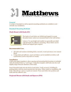


© Copyright 2026