
The use of slow waves to design simple sound absorbing materials
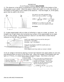
JOURNAL OF APPLIED PHYSICS 117, 124903 (2015)
The use of slow waves to design simple sound absorbing materials
!gan
J.-P. Groby,a) W. Huang, A. Lardeau, and Y. Aure
Laboratoire d’Acoustique de l’Universit!
e du Maine (LAUM), UMR-6613 CNRS, Av. O. Messiaen,
72085 Le Mans, France
(Received 16 September 2014; accepted 5 March 2015; published online 25 March 2015)
We demonstrate that the phenomenon of slow sound propagation associated with its inherent
dissipation (dispersion þ attenuation) can be efficiently used to design sound absorbing
metamaterials. The dispersion relation of the wave propagating in narrow waveguides on one side of
which quarter-wavelength resonators are plugged with a square lattice, whose periodicity is smaller
than the wavelength, is analyzed. The thermal and viscous losses are accounted for in the modeling.
We show that this structure slows down the sound below the bandgap associated with the resonance
of quarter-wavelength resonators and dissipates energy. After deriving the effective parameters of
both such a narrow waveguide and a periodic arrangement of them, we show that the combination
of slow sound together with the dissipation can be efficiently used to design a sound absorbing metamaterial which totally absorbs sound for wavelength much larger than four times the thickness strucC 2015 AIP Publishing LLC.
ture. This last claim is supported by experimental results. V
[http://dx.doi.org/10.1063/1.4915115]
I. INTRODUCTION
Slow sound propagation is currently a growing topic in
acoustics because of the direct analogy with electromagnetic
induced transparency. This phenomenon appears when an
opaque medium exhibits enhanced transmission in a narrow
frequency windows along with strong dispersions. This
rapid change in transmission leads to strong dispersion giving rise to slow phase or group velocity waves whose frequency is centered on the narrow transmission band.1 In
acoustics, most of theoretical and experimental evidences of
slow sound have been achieved by considering sound propagation in pipes with a series of detuned resonators (mostly
Helmholtz resonators) separated by a subwavelength distance,2 tuned or detuned resonators separated by half of the
wavelength giving rise to a coupling between the resonators
and the Bragg bandgap,3 in a waveguided sonic crystals,4 in
lined ducts.5 So far, only a few studies have been focusing
on the dissipation (dispersion and attenuation) of slow sound
propagation, even if it has been sometimes noticed or discussed.2,3,6,7 Dissipation was considered as a side effect of
an unexpected adverse reaction. The key point of this article
is to make use of slow sound propagation, which appears for
a broadband frequency below the bandgap associated with
resonator’s resonance, together with the associated dissipation to design a sound absorbing metamaterial. By sound
absorbing metamaterials, we mean a structured material that
exhibits strong or total absorption for wavelength in the air
much larger than four times the thickness of the structure L
when rigidly backed. Effectively, usual sound absorbing
materials, mainly foams, suffer from a lack of absorption at
low frequencies when compared to their efficiency at higher
frequencies. This results in bulky and heavy multilayered
structures, which are mainly efficient for frequencies higher
a)
Electronic mail: [email protected].
0021-8979/2015/117(12)/124903/9/$30.00
than the so-called quarter wavelength resonance of the
backed layer in the inertial regime, i.e., f ¼ c/4 L. The speed
of sound in current porous material is usually of the same
order of the sound speed in the air in this regime, because it
pffiffiffiffiffiffi
tends asymptotically to cair = a1 , where the tortuosity a1
is usually around unity for usual sound absorbing porous
materials. The interest of slow sound obviously appears
because decreasing the speed of sound in the structure at
fixed thickness results in a decrease of the first maximum
absorption frequency or decreasing the speed of sound in
the structure at fixed frequency results in a decrease of the
structure thickness. Over the last decades, several solutions
have been proposed to design sound absorbing metamaterials: membrane-type metamaterials that exhibit nearly total
reflection at an anti-resonance frequency8 or nearly total
absorption due to the flapping motion of asymmetric rigid
platelets added to the membrane9 have been proposed, but
their absorption properties are limited in the metamaterial
resonance frequency range; metaporous materials that exhibit quite large total absorption frequency band due to the
coupling of several resonance phenomena arising from the
embedment of resonant inclusions in a porous matrix,10 possibly coupled with surface irregularities; double porosity
materials11 or, more recently, dead-end porosity materials.12
This last solution consists in plugging dead-end pores, i.e.,
quarter-wavelength resonators, on open pores to create
dead-end porosity materials. The derived model consists in
adding the admittance of the porous material without the socalled dead-end pores with the one of the so-called dead-end
pores, resulting in a low frequency domain of validity of the
model and difficulties to understand absorption mechanism.
Moreover, the manufacturing process (cooling process)
involving salt grains and liquid metal does not yet offer the
possibility of the full control over the densities and the
lengths of the dead-end pores.
117, 124903-1
C 2015 AIP Publishing LLC
V
[This article is copyrighted as indicated in the article. Reuse of AIP content is subject to the terms at: http://scitation.aip.org/termsconditions. Downloaded to ] IP:
213.245.132.172 On: Wed, 25 Mar 2015 20:20:41
124903-2
Groby et al.
J. Appl. Phys. 117, 124903 (2015)
In this article, we analyze a periodic structure composed
of a periodic arrangement of narrow slits, on one side of
which quarter-wavelength resonators are plugged with a
square lattice, whose periodicity is very small compared to
the wavelength. After a description of the configuration in
Sec. II and solution of the problem in Sec. III, Sec. IV
presents the dispersion analysis of the modes traveling in
one of this narrow irregularity and Sec. V presents the derivation of the effective parameters together with their
domains of validity. Below the band gap associated with the
resonance quarter-wavelength resonators, the sound speed
inside the narrow irregularities presents the characteristic of
slow sound with an associated dissipation. This enable to
design a sound absorbing metamaterial possessing absorption peaks for wavelength in the air much larger than the
structure thickness as shown in Sec. V and experimentally
validated in Sec. VI.
II. DESCRIPTION OF THE CONFIGURATION
A unit cell of the 2D (in reality 3D) scattering problem
together with a sketch of one internal face of the narrow
irregularity (subsequently named slit) is shown in Fig. 1.
Before the addition of the quarter-wavelength resonators, the
unit cell is composed of N identical irregularities of width w
and height L occupied by a material Ms modeled as a slit,
i.e., the viscous and thermal losses at each lateral boundaries
are accounted for. When only plane waves propagate in a
slit, the equivalent complex and frequency depend densities
and bulk modulus are13
cP
" pffiffiffiffiffiffiffiffiffiffiffiffiffiffiffiffi0ffiffiffiffiffiffiffi#$" pffiffiffiffiffiffiffiffiffiffiffiffiffiffiffiffiffiffiffiffiffiffiffi# ;
w
w
1 þ ðc # 1Þtanh
#iqa Prx=g
#iqa Prx=g
2
2
qa
" pffiffiffiffiffiffiffiffiffiffiffiffiffiffiffiffiffiffi# " pffiffiffiffiffiffiffiffiffiffiffiffiffiffiffiffiffiffi# ;
qs ¼
w
w
1 # tanh
#iqa x=g =
#iqa x=g
2
2
Ks ¼
wherein c is the specific heat ratio, P0 the atmospheric pressure, Pr the Prandtl number, g the dynamic viscosity, and qa
the density of the saturating fluid. The upper and lower flat
and mutually parallel boundaries of the structure, whose x2
coordinates are L and 0, are designated by CL and C0,
respectively.
The upper semi-infinite material Ma, i.e., the ambient fluid
that occupies Xa, and Ms are in a firm contact at the boundaries
CðnÞ
as ; 8n 2 N , meaning that the pressure and normal velocity
are continuous across CðnÞ
as . The thermal losses are neglected
on C0 and CL and a Neumann type boundary condition is
applied on these boundaries, i.e., the normal velocity vanishes
Kt ¼
qt ¼
on C0 and CL. The n-th slit is located at x1 ¼ d(n), which refers
to the slit boundary on which a Neumann type boundary condition is applied, i.e., the interface CN.
A periodic set of r in radii quarter-wavelength resonators of length l are plugged on one lateral face of the slit with
a square lattice of size a in the x2–x3 plane, see Fig. 1. The
material Mt that occupies each tube Xt is modeled as a circular tube and is in firm contact with Ms through Cst, i.e.,
the pressure and normal velocity are continuous across
Cst. When only plane waves propagate in a tube, the equivalent complex and frequency depend densities and bulk
modulus are13
cP0
% pffiffiffiffiffiffiffiffiffiffiffiffiffiffiffiffiffiffiffiffiffiffiffi& ;
pffiffiffiffiffiffiffiffiffiffiffiffiffiffiffiffiffiffiffiffiffiffiffi % pffiffiffiffiffiffiffiffiffiffiffiffiffiffiffiffiffiffiffiffiffiffiffi&
a
1 þ 2ðc # 1Þ= #iq Prx=gJ1 r #iqa Prx=g =rJ0 r #iqa Prx=g
qa
% pffiffiffiffiffiffiffiffiffiffiffiffiffiffiffiffiffiffi& ;
pffiffiffiffiffiffiffiffiffiffiffiffiffiffiffiffiffiffi % pffiffiffiffiffiffiffiffiffiffiffiffiffiffiffiffiffiffi&
1 # 2= #iqa x=gJ1 r #iqa x=g =rJ0 r #iqa x=g
wherein Jn is the Bessel function of n-th order. The thermal
losses are neglected on Cl and a Neumann type boundary condition is applied on these boundaries, i.e., the normal velocity
vanishes on Cl. The first conditions on Cst will be reduced to
an impedance condition applied on the whole interface CZ in
the following, because the considered wavelength is much
larger than the dimensions of Cst and the periodicity of this
arrangement a inside the slit. This impedance, which already
(1)
(2)
accounts for the material propagation and losses in the tubes,
and for the conditions on Cst and Cl reads as
(3)
Z 6 ¼ 6iZ t cotanðkt lÞ=/t ;
ffi
ffi
ffi
ffi
ffi
ffi
ffi
ffi
p
t
t
wherein Z t ¼ qt K t is the impedance of M , k is the wavenumber inside the tube, and /t is the ratio between the area of
Cst over the one of the unit cell, i.e., a surface porosity
/t ¼ pr2 =a2 . The sign 6 depends on whether the tubes are
[This article is copyrighted as indicated in the article. Reuse of AIP content is subject to the terms at: http://scitation.aip.org/termsconditions. Downloaded to ] IP:
213.245.132.172 On: Wed, 25 Mar 2015 20:20:41
124903-3
Groby et al.
J. Appl. Phys. 117, 124903 (2015)
The reflection coefficient of the Bloch wave denoted by the
subscripts q is Rq.
According to Ref. 15, the pressure field ps(n), admits the
pseudo-modal representation, that already accounts for the
boundary conditions on C0, CN and CZ:
X
s
s
An cos ðk1m
ðx1 # d ðnÞ ÞÞ cos ðk2m
x2 Þ8x 2 XsðnÞ ;
psðnÞ ¼
m2N
(7)
wherein An are the coefficients of the pseudo modal repreqffiffiffiffiffiffiffiffiffiffiffiffiffiffiffiffiffiffiffiffiffiffiffiffiffiffiffi
s
s
s 2
sentation, k2m
¼ ðks Þ2 # ðk1m
Þ , with Reðk2m
Þ ) 0 and
s
s
Imðk2m
Þ ) 0, and k1m
is the m-th solution of the dispersion
relation and satisfies
FIG. 1. Example of a d-periodic structure, whose unit cell is composed of 2
slits with quarter-wavelength resonators plugged on one side of them.
plugged on the right (þ sign) or left (– sign) side of the slit. In
what follows, only the positive sign will be used and Z ¼ Zþ.
The problem therefore reduces to a 2D one. The impedance
condition does not account for losses on the rigid portion of
CZ, i.e., CZ\Cst, while use of Eq. (1) accounts for losses on a
fully rigid boundary. The combination of Eq. (1) and the
application of this impedance condition are also valid under
the hypothesis of small /t . This hypothesis is usually accepted
when dealing with dissipation in ducts with resonators.7,14
The incident wave propagates in Xa and is expressed by
i
ai
i
p ðxÞ ¼ Ai eiðk1 x1 #k2 ðx2 #LÞÞ , wherein k1i ¼ #ka sin hi ; k2ai ¼
i
i
a
k cos h and A ¼ Ai(x) is the signal spectrum.
In each domain Xa (a ¼ a, s, t), the pressure field fulfills
the Helmholtz equation
"
#
ðk a Þ2 a
1
a
r&
rp
p ¼ 0;
þ
qa
qa
(4)
with the density qa and the wavenumber ka ¼ x/ca, defined
as the ratio p
between
ffiffiffiffiffiffiffiffiffiffiffiffi the angular frequency x and the sound
speed ca ¼ K a =qa .
As the problem is periodic and the excitation is due to a
plane wave, each field (X) satisfies the Floquet-Bloch relation
i
Xðx þ dÞ ¼ XðxÞeik1 d :
(5)
Consequently, it suffices to examine the field in the elementary cell of the material to get the fields, via the Floquet relation, in the other cells.
III. SOLUTION OF THE PROBLEM
' s ( #ixqs
s
:
tan k1m
w ¼
k1m
Z
This last equation is solved by use of a Muller’s algorithm16
initiated with the low frequency approximations
pffiffiffiffiffiffiffiffiffiffiffiffiffiffiffiffiffiffiffiffiffi
s
k~10 ¼ #ixqs w=Z=w; and
qffiffiffiffiffiffiffiffiffiffiffiffiffiffiffiffiffiffiffiffiffiffiffiffiffiffiffiffiffiffiffiffiffiffiffiffiffiffiffiffi
s
(9)
k~1m ¼ mpð1 þ 1 # 4ixqs w=ZðmpÞ2 Þ=2w:
These modes are said bi-orthogonal and the bi-orthogonality
relation reads as
ðw
s
s
s
cos ðk1m
x1 Þ cos ðk1M
x1 Þdx1 ¼ dMm wð1 þ sincð2k1m
wÞÞ=2
0
¼ dMm wNm :
Separation of variables, radiation conditions, and
Floquet theorem leads to the representations
X
a
a
a
½Ai e#ik2q ðx2 #LÞ d0q þ Rq eik2q ðx2 #LÞ (eik1q x1 ; 8x 2 Xa ;
pa ðxÞ ¼
q2Z
(6)
a
wherein d0q is the Kronecker symbol, k1q
¼ k1i þ 2qp
d , and
qffiffiffiffiffiffiffiffiffiffiffiffiffiffiffiffiffiffiffiffiffiffiffiffiffiffiffi
2
2
a
a
a
a
a
k2q ¼ ðk Þ # ðk1q Þ , with Reðk2q Þ ) 0 and Imðk2q Þ ) 0.
(10)
B. The linear system for the solution of Rq
The application of the boundary conditions on each
interface CðnÞ
as leads to two set of coupled equations in terms
of AðnÞ
m and Rq: the continuity of the pressure field is projected on each Bloch mode (making use of the orthogonality
of these modes), while the continuity of the normal component of the velocity is projected on the mode of the slit (making use of the bi-orthogonality relation (10)). The
combination of these two set of equations leads to the solution either in terms of Rq or in term of Am, these two solutions being linked one with each other. In particular, the
linear system of equations for the solution for Rq, 8q 2 Z, is
X X ks /sðnÞ
' s ( l=rðnÞ# l=rðnÞþ
iqa X
2m
RQ
tan k2m
L Imq
ImQ
Rq # a
s
k2q Q2Z
q Nm
n2N m2Z
¼ Ai dq þ Ai
A. Field representations
(8)
X X iqa ks /sðnÞ
' s ( ðnÞ# ðnÞþ
2m
tan k2m
L Imq ImQ ;
a
s
k2q q Nm
n2N m2Z
(11)
sðnÞ
where / ¼ w=d is the surface porosity of one slit, such
that [n2N /sðnÞ ¼ /s is the global surface porosity of the
structure, and
e6ik1q ðd
2
a
ðnÞ #w
2
Þ*
"
'
s
a (w
k1m
6k1q
2
"
#+
'
(
w
s w
s
a
;
7k1q
þe#ik1m 2 sinc k1m
2
ðnÞ6
¼
Imq
s w
eik1m 2 sinc
#
(12)
[This article is copyrighted as indicated in the article. Reuse of AIP content is subject to the terms at: http://scitation.aip.org/termsconditions. Downloaded to ] IP:
213.245.132.172 On: Wed, 25 Mar 2015 20:20:41
124903-4
Groby et al.
J. Appl. Phys. 117, 124903 (2015)
when the impedance condition is applied on the right side of
the n-th slit and
e6ik1q ðd
2
a
ðnÞ þw
2
Þ*
"
s
a (w
k1m
6k1q
2
"
#+
' s
s w
a (w
;
7k1q
þeik1m 2 sinc k1m
2
ðnÞ6
¼
Imq
s w
e#ik1m 2 sinc
'
#
(13)
when the impedance condition is applied on the left side of
the n-th slit.
The system Eq. (14) is solved for each q and each m.
The absorption coefficient A is then calculated through
' a(
X Re k2q
A¼1#
k Rq k2 :
(14)
a
k
2
q2Z
IV. ANALYSIS OF THE DISPERSION RELATION IN THE
SLITS
The width of the slit, tube dimensions, and the square lattice dimension is fixed at w ¼ 2 mm, r ¼ 2.5 mm, l ¼ 40 mm,
and a ¼ 7 mm. The surface porosity /t is 0.4. Figure 2 depicts
the real part of solution of the dispersion relation Eq. (8) with
and without losses. In this last case, qs ¼ qt ¼ qa and
Ks ¼ Kt ¼ Ka. The 0-th order mode possesses a cut-off
frequency with an infinite branch when cotan(ktl)
¼ cotan(kal) ¼ 0. This make the higher modes continuously
shift down of a value of p/w, which means that these modes
change symmetry, from a symmetric to an antisymmetric one,
and the opposite. The impedance condition continuously
passes from a condition close to a Neumann one at low frequency to a Neumann one at higher frequency through a
Dirichlet one at the resonance of the tubes. When losses are
introduced, and for small values of w, these modes do not
intersect anymore and do not change symmetry. This implicitly
means that a Dirac cone is theoretically possible with mode
repulsion for particular couple (w, l). These modes are cors
rectly approximated by their low frequency approximation k~1m
s
given Eq. (9). The real part of k is also plotted in Figure 2.
s
Only the fundamental mode k~10 leads to propagative waves.
s
s
FIG. 2. Real part of k1m
w, without and with losses, as well as k~10 w. The real
s
part of k w is also plotted, as well as the position of both bounds of the
bandgap fl and fh.
This fundamental mode is close to a plane mode when propas
gative, because k~10 w * p. This fact together with the small
t
value of / ensure the validity of the combination of Eq. (1)
with the application of this impedance condition. The structure
possesses a bandgap associated with the resonance of the
quarter-wavelength resonators. Because of the losses, the
bandgap definition and bounds are not clear. Nevertheless, it
s
corresponds to k~10 ¼ ks , i.e., tan kt l ¼ #ks wZ t =Z s /t .
Assuming all properties of the materials to be frequency independent and real, the low frequency bound corresponds to the
first sign change of tanðkt lÞ, i.e., fl + ct/4l, while the high frequency bound corresponds to tanðkt lÞ + kt l # p, i.e.,
fh ¼ 1=ð2ðl=ct þ wZt =cs Zs /t ÞÞ. When the material properties
are frequency dependant, these two frequencies can be determined by the intersection of the real part of the previous
expression with f. This leads to fl + 2080 Hz and fh + 3890 Hz,
whose value highlight the difficult determination of the
bandgap bounds in case of losses and dispersion. While fl corresponds to the quarter wavelength frequency of the tubes, fh
also depends on various parameters among which the dimensions and mechanical parameters of the slit. This explain why
fh is that affected when compared to fl by the flow in duct
experiments, for example.5
Among the bandgap, a particular feature of the sound
wave propagating in the slit is its velocity. Figure 3(a) depicts
the sound speed of the wave traveling in the slit, i.e.,
s
s
Þ, its approximation, i.e., Reðx=k~20 Þ, the sound
Reðx=k20
speed of air and
speed in the slit in absence of tubes
pffithe
ffiffiffiffiffiffiffisound
ffiffiffi
Reðcs Þ ¼ Reð js =qs Þ. Four zones are exhibited: At very low
frequency, sound speed vanishes because of the viscous regime; below fl, the sound speed is smaller than the speed of
sound in the air and in the slit in absence of tubes, i.e., subsonic regime; inside the bandgap [fl, fh], the sound speed vanishes; above fh, the sound speed is higher than the air speed of
sound, i.e., supersonic regime. Notice that again the bandgap
does not seem to have the same bounds as before, because of
the losses and dispersion. The supersonic regime was already
noticed in Ref. 17 over a small frequency range just after
Helmholtz resonance, while the infrasonic regime is to some
extend (in the sense that an acoustic wave always propagate
in a porous medium with a velocity a little bit smaller than in
the air) common in the porous community. Nevertheless, we
clearly demonstrate hereafter that this infrasonic regime is not
due to a common tortuosity effect. Below fl, the sound speed
possesses a plateau at low frequency and slowly decreases to
a value close to zero at fl. The value of this plateau can be
t
approximated
pffiffiffiffiffiffiffiffiffiffiffiffit(k
ffiffiffiffiffilffiffiffiffiffi*
ffiffiffiffiffiffiffiffiffi1)
ffiffiffiffi by the low frequency limit
s
Reðc = 1 þ / lZs cs =wZt ct Þ, Figure 3(a). This value is
s
t
always much smaller thanpRe(c
ffiffiffiffiffiffiffiffiffi)ffiffiffitif
ffiffiffiffiffi/ffiffiffi l > w. Without losses,
a
this limit reduces to c = 1 þ / l=w, which clearly shows
that the speed of sound in the slit is always smaller than ca
and decreases when the ratio /t l=w increases. Focusing on the
frequency band below fl, the group velocity, defined as vsg
s
¼ Reð@x=@k20
Þ is also much lower than the speed of sound
in the air and tends to zeros at fl.
s
Þ. Figure 3(b)
The absorption is related to Imðk20
s
s
depicts Imðk20 Þ in the slit and its approximation Imðk~20 Þ.
s
The imaginary part of k20 is very large inside the bandgap.
[This article is copyrighted as indicated in the article. Reuse of AIP content is subject to the terms at: http://scitation.aip.org/termsconditions. Downloaded to ] IP:
213.245.132.172 On: Wed, 25 Mar 2015 20:20:41
124903-5
Groby et al.
J. Appl. Phys. 117, 124903 (2015)
FIG. 3. (a) Real part of cs2 (—) and of c~s2 (– –), as well as cair ( - ) and Re(cs) (& & &). The asymptotic low frequency limit of cs2 is also plotted (!). (b) Imaginary
s
part of k2s (—) and of k~2 (– –). The asymptotic low frequency limit of Imðk2s Þ is also plotted (!).
s
The low frequency limit (ktl * 1) of Imðk~20 Þ is
pffiffiffiffiffiffiffiffiffiffiffiffitffiffiffiffiffiffiffiffiffiffiffiffiffiffiffiffiffiffiffiffiffiffiffi
Imðks 1 þ / lZ s cs =wZt ct Þ, which clearly show that the
absorption increases with the ratio /t l=w. So, to ensure low
sound speed and large attenuation, the ratio /t l=w should
be large.
function windowing and could make I0qðnÞ6 large for q 6¼ 0.
The contribution of these evanescent waves, which are localized close to the interface of the material can nevertheless be
accounted for through Drude transition layers.19,20
s
a
When ðk10
6k1q
Þw=2 , 1; 8q 6¼ 0, the system Eq. (11)
reduces to the unique calculation of R0, which reads as
V. DERIVATION OF THE EFFECTIVE PARAMETERS
Assuming the unique propagation of the mode m ¼ 0 in
s
w * 1; N0 + 1. The assumption that the frethe slits and k10
quency is much lower than the Wood anomaly frequency,
a
which corresponds to k1q
¼ ka when q ¼ 61, i.e., when only
the specularly reflected wave propagates, is not sufficient to
ðnÞ6
derive effective parameters because of the terms I0q in
s
a
Eq. (11). To do so, the condition ðk10 6k1q Þw=2 , 1; 8q 6¼ 0
should be imposed. This condition ensures that only the term
q ¼ 0 does not vanish and that I00ðnÞ6 ¼ 1. It implicitly means
that the position of slits d(n) as well as the side of the slit on
which the impedance condition is applied, either on the right
or the left of the slit, does not affect the effective parameters.
In other words, it means that different structure of different
periodicity can have identical effective parameters. This last
condition is more restrictive than the first one, because it
also ensures that the higher order Bloch modes, which are
only related to the arrangement of the slits, do not contribute
to the field, while qp/d is always very large. This condition
is often forgotten by the porous material community, which
mainly focuses on the propagation inside the pores, a few on
their arrangement, but never on the possible contribution
of evanescent waves. Effectively, the macroscopic description of the propagation inside the slit is subjected to
s
a * 1. The macroscopic descripk1s w * 1; kt r * 1, and k20
tion of the propagation inside the material is also subjected
a
to ðk1s 6k1q
Þw=2 , 1; 8q 6¼ 0. In the frequency range, where
a
< ka when q ¼ 61 is satisfied, but the conthe condition k1q
s
a
dition ðk10 6k1q Þw=2 , 1; 8q 6¼ 0 is not satisfied, the higher
order Bloch modes do not propagate but can contribute significantly to the field and so to the properties of the material.
s
close to the resoThis is due to the large dispersion of k10
nance frequency of the resonators, which shifts the sinc
R0 ¼ Ai
s
s
ixqs cotð k20
LÞ=k20
/s # Z0 = sin hi
:
s
s
ixqs cotð k20 LÞ=k20 /s þ Z0 = sin hi
(15)
A simple identification with the classical formula of the
reflection coefficient of a rigidly backed homogeneous slab
leads to a surface impedance
s
s
LÞ=k20
/s :
Z ¼ ixqs cotðk20
(16)
This impedance does not depend on the angle of incidence.
Sound propagation in each slit depends only on the pressure
of air above the slit, and the material is a locally reacting material.21 Another simple identification leads to Ze f f ¼
s
s
xqs =k~2 /s and ke f f ¼ k~2 , where we make use of Eqs. (3) and
(9), the validity of these expressions being ensured. The effective density (qe f f ¼ Ze f f ke f f =x) and bulk modulus
(Ke f f ¼ xZe f f =ke f f ) of this locally reacting material would
read as qef f ¼ qs =/s ; Kef f ¼ K s =/s ð1þZ s /t tanðkt lÞ=Z t ks wÞ.
Nevertheless, these formula are derived accounting for the
unique porosity of the slit and not for the porosity of the
whole structure. Doing so, the effective density and bulk modulus of this locally reacting material read as
'
(
qs 1 þ /t l=w
;
qe f f ¼
/tot
'
(
K s 1 þ /t l=w
(;
Ke f f ¼ tot '
(17)
/ 1 þ Z s /t tanðkt lÞ=Z t ks w
where /tot is the porosity of the whole structure and a1 ¼
ð1 þ /t l=wÞ ¼ /tot =/s is a tortuosity-like parameter. In this
last case, limx!0 Ke f f ¼ P0 , which is the usual value limit of
the bulk modulus in the classical porous material representation. These effective parameters are independent on wave
[This article is copyrighted as indicated in the article. Reuse of AIP content is subject to the terms at: http://scitation.aip.org/termsconditions. Downloaded to ] IP:
213.245.132.172 On: Wed, 25 Mar 2015 20:20:41
124903-6
Groby et al.
J. Appl. Phys. 117, 124903 (2015)
propagation direction and structure thickness. The effective
density and bulk modulus in the slits are qse f f ¼ qe f f /tot
¼ qs ð1 þ /t l=wÞ and Kes f f ¼ Ke f f /tot , i.e., a unusual tortuosity is introduced and the effective bulk modulus is modified.
The addition of the periodic set of resonators acts on the thermal
losses and introduces an unusual tortuosity, which acts on the
density of the slit and not on a mixture of the densities of the slit
and of tubes. To be convinced of the influence of the thermal
losses, the assumption ktl * 1 leads to Kes f f ¼ K s ð1 þ /t l=wÞ
=ð1 þ /t K s l=wK t Þ, which only depends on the effective bulk
modulus in the tube and the slit and so on the thermal losses.
Let us consider N ¼ 1, and the dimension used in
Sec. IV with d ¼ 42 mm. This corresponds to a very thin
plate ending the quarter wavelength resonator. Figure 4
depicts the normalized real and imaginary part of the effective bulk modulus and density as well as their approximation: normalized by P0 =/tot and by qa =/tot for the material
and normalized by P0 for the material and by qa for the slit.
The effective parameters for the materials are only valid till
fl, while the effective parameters for the slit are valid on the
whole range of frequency considered. A particular feature of
the real part of the effective modulus in the slit is that it
becomes negative on the whole frequency of the bandgap
associated with the resonance of the resonators. This is in accordance with previous results obtained in case of Helmholtz
resonators17 since the seminal article.18 A particular feature
of the real part of the density is its particularly large value,
which is due to a particularly large tortuosity-like effect only
acting on the density of the slit. Imaginary part of both effective parameters is in accordance with the passivity condition,20 with Im(Keff) < 0 and Im(qeff) > 0.
Let us remark that the extension to a 3D problem with
quarter-wavelength resonators plug on a straight pore is straightforward, by defining the proper porosity and using the proper
formulas for the effective parameters for the straight pore.
VI. RESULTS AND DISCUSSION
The infinite sums in Eq. (11) are truncated at M and
Q 6 . The goal is to design a material that achieves large
FIG. 4. Normalized real and imaginary part of the effective bulk modulus
(a) and density (b) as well as their approximation. Solid curves depict the
direct calculation of the effective parameters through k1s , while the dashed
curves depict their approximated values Eq. (17).
absorption at low frequency. Low frequency means for a
wavelength in the air larger than four times the thickness of
the structure, where only one reflected Bloch wave is propagating. The high frequency bound can be approximated by
the frequency at which the Wood anomaly happens.22
In our case, the large absorption is only associated with
the quarter wavelength resonance of the slits. Contrary to the
one usually encountered for regular porous material and
associated with interference phenomena, this quarter wavelength resonance is a real resonance of the slits. For fixed ratio /l=w, Figure 3 shows that the sound speed decreases
from a plateau, while the attenuation Imðk2s Þ increases with
frequency below the bandgap. This means that the structure
possesses an optimum in terms of attenuation-thickness of
the structure at the quarter wavelength resonance of the slit
when the frequency of the end of the plateau fopt equals
cs2 =4L. For the dimensions considered in Sec. IV, fopt
+ 550 Hz, which leads to L + 45 mm. In practice, this length
can be smaller. Figure 5(a) depicts the absorption coefficient
for d ¼ 84 mm, L ¼ 42 mm, N ¼ 2, with d(1) ¼ d(2) ¼ 42 mm
(the other dimensions are those of Sec. IV), with the quarter
wavelength resonators plugged on the left for the first slit
and on the right for the second slit, when M ¼ 2 and
Q 6 ¼ 0, Q 6 ¼ 22 as well as the calculation ran with the
equivalent parameters derived in Sec. V at normal incidence.
It should be noticed that in this case, the equivalent parameters being independent of the slit position and side of the slit
on which the impedance condition is applied, the effective
parameters reduce to those of N ¼ 1 and d 0 ¼ 42 mm. Their
validity is ensured till the quarter-wavelength resonance.
The calculation performed with the help of the effective parameters is identical (as expected) with the calculation performed when only the terms Q ¼ 0 is dominant. While the
calculation derived with the effective parameters constitutes
a good approximation, the effect of the Drude transition
layers19 is clearly visible around this bound, fl. Effectively,
the required number of Bloch mode is very large at the lower
bound of the bandgap. This is explained by the large dispersion of the waves inside the slits around this frequency. The
absorption coefficient vanishes inside the bandgap because
all the energy is reflected. The structure response possesses
absorption peaks which all correspond to resonances of the
slits.
The large absorption obtained at 590 Hz is of particular
interest. It should be noticed that this peak is not associated
with the resonance of the resonators but to a resonance of the
slit with a sound velocity reduced because of the presence of
the side resonators. In first approximation, the sound speed is
pffiffiffiffiffiffiffiffiffiffiffiffiffiffiffiffiffiffiffiffi pffiffiffiffiffiffi
reduced by a factor 1 þ /t l=w ¼ a1 + 3. Thus, this material will be efficient at a frequency 3 times smaller than a
classical one. This frequency corresponds in practice to a
wavelength in the air ka ¼ 579.6 mm, which is 14 times bigger than the thickness of the structure. The higher order quarter wavelength resonances lead to large absorption peak,
which concentrates around fl because the speed of sound is
rapidly decreasing around this value. The measurement of
this resonance could be used to analyze back the speed of
sound inside the slits.
[This article is copyrighted as indicated in the article. Reuse of AIP content is subject to the terms at: http://scitation.aip.org/termsconditions. Downloaded to ] IP:
213.245.132.172 On: Wed, 25 Mar 2015 20:20:41
124903-7
Groby et al.
J. Appl. Phys. 117, 124903 (2015)
FIG. 5. Absorption coefficient for L ¼ 42 mm, N ¼ 2, with d(1) ¼ d(2) ¼ 42 mm, with the quarter wavelength resonators plugged on the left for the first slit and
on the right for the second slit, when M ¼ 2 and Q 6 ¼ 0, Q6 ¼ 22 as well as the calculation ran with the equivalent parameters, (a) normal incidence, and (b)
hi ¼ p/4.
Figure 5(b) depicts the absorption of the same configuration at hi ¼ p/4, when 3 modes are accounted for in the slits
and Q6 ¼ 22 as well as the calculation ran with equivalent
parameters derived in Sec. V. The bandgap frequency range
and the position of the absorption peaks are identical,
because the bandgap is due to quarter wavelength resonance
of the tubes and because the large absorption peaks correspond to resonances of the slits. In practice, the calculation
performed with the use of the effective parameters is in good
agreement below the bandgap till grazing incidence despite
the first Wood anomaly (which appears around 2100 Hz,
Figure 5(b)).
The amplitude and frequency of the first absorption
peak can further be improved with the help of the ratio
w=/t l, as explained in Sec. IV. This validates the previously
effective parameters below the bandgap and proves the efficiency of the structure as sound absorbing metamaterial.
VII. EXPERIMENTAL VALIDATION
The samples were composed of an aluminum block of
40 - 42 - 42 mm3. The block was drilled from side to side
along the 40 mm thick direction with circular holes of
r ¼ 2.5 mm equally spaced of 7 mm as shown Figure 5(a).
This constitutes Sample 1. A 1 mm thick aluminum plate
was then glued on one side of Sample 1 to close the holes.
This constitutes Sample 2.
The absorption coefficient of the sample is measured in
an impedance tube with a square cross section
4.2 cm - 4.2 cm. The tube cut-off frequency is 4200 Hz. By
assuming that plane waves propagate below the cut-off frequency, the infinitely rigid boundary conditions of the tube
act like perfect mirrors and create a periodicity pattern in the
x1 and x3 directions. Samples 1 and 2 are placed at the end of
the tube against a copper plug that closes the tube and acts as
a rigid boundary, therefore creating a periodicity along the x1
direction of 8.4 cm with slit width w ¼ 2 mm and w ¼ 1 mm,
respectively, see Figure 5(a). This technique was previously
used in various articles10,23 and allows to determine experimentally the absorption coefficient at normal incidence of a
quasi-infinite 2D periodic structure just with half or a quarter
of the unit cell.
Figure 6(b) depicts the experimental absorption coefficient of Sample 1, the calculated one in the corresponding
case, i.e., the one studied in Sec. VI and its approximation
with the effective parameters. All the three curves match well
below the bandgap. As explained in Sec. V, only the fully calculated absorption coefficient is valid inside the bandgap.
Inside the latter, the experimental absorption coefficient is
very low and is also difficult to measure, explaining the oscillations of the experimental curve. Figure 6(c) depicts the
same curves for Sample 2, i.e., in the case w ¼ 1 mm. Once
again the curves match well. A small disagreement is noticed
around fl. This can be explained by several things related to
the manufacturing and the misplacement of the sample, but
more surely by the use of the impedance model. Effectively,
the wavelength (Reðcs2 =f Þ) is very small (while on the other
hand the imaginary part Imðcs2 =f Þ is very large) and can be
comparable to a around fl, making improper the impedance
model around this frequency. In both cases, the absorption for
frequency higher than fh is not well measured because the
absorption is very low, but also because this frequency is very
close from the cut-off frequency of the tube. These experiments were performed at two different levels of excitation,
with identical results, ensuring the linearity of the response.
These two experiments validate the previous method of calculation, as well as the derived effective parameters.
Of particular interest is the absorption coefficient of
Sample 2, which exhibits a total absorption peak at 480 Hz,
which corresponds to a wavelength in the air medium 17
times larger than the structure thickness.
VIII. CONCLUSION
The acoustic properties of a periodic arrangement of
narrow irregularities (slits) with quarter-wavelength resonators plugged on it with a square lattice, whose periodicity is
smaller than the wavelength is analyzed. It is shown that the
wave propagating in the slit possesses the specific features of
slow sound propagation over a quite large frequency band
[This article is copyrighted as indicated in the article. Reuse of AIP content is subject to the terms at: http://scitation.aip.org/termsconditions. Downloaded to ] IP:
213.245.132.172 On: Wed, 25 Mar 2015 20:20:41
124903-8
Groby et al.
J. Appl. Phys. 117, 124903 (2015)
clearly show that the slow down of the sound speed in the
slit is due to a modified bulk modulus together with an unusual tortuosity effect acting on the density of the slit. Both
sound speed and dissipation are then used to design sound
absorbing metamaterials, which exhibit a lowest frequency
total absorption peak for wavelength much larger than four
times the thickness of the structure. These results are validated experimentally, showing a lowest frequency total
absorption peak for wavelength 17 times larger the thickness
of the structure. This paves the way to the design of more
complex sound absorbing structures, involving resonators of
different nature, detuned resonators, and more complex
arrangement.
ACKNOWLEDGMENTS
This work was partly supported by the ANR Project
METAUDIBLE No. ANR-13-BS09-0003 co-founded by
ANR and FRAE.
The authors would like to thank C. Boutin, B. Nennig,
O. Umnova, and A. Merkel, for useful discussions on this
work.
1
FIG. 6. Picture of Sample 1 (a), absorption coefficient of Sample 1 measured
and simulated with the full model and with the effective parameters (b), and
absorption coefficient of Sample 2 measured and simulated with the full
model and with the effective parameters (c).
with a phase (and group) velocity much smaller than the one
of air and the one of the wave propagating in the slit in absence of the quarter-wavelength resonators, for all frequencies below the resonance of the resonators. The associated
dissipation is analyzed showing strong dependence with
regards to the surface porosity, length of resonators, and
width of the slit. The effective parameters are then derived,
both for the modeling of the sound propagation in one slit,
exhibiting negative bulk modulus inside the bandgap, and
for the modeling of the whole structure, exhibiting in addition a unusual tortuosity effect. Of particular interest is the
frequency limit of these effective parameters which are
clearly identified, also pointing the interest of the use the
Drude transition layers. These effective parameters also
L. Hau, S. Harris, Z. Dutton, and C. Behroozi, “Light speed reduction to
17 metres per second in an ultracold atomic gas,” Nature 397, 594–598
(1999).
2
A. Santillan and S. Bozhevolnyi, “Demonstration of slow sound propagation and acoustic transparency with a serie of detuned resonators,” Phys.
Rev. B 89, 184301 (2014).
3
G. Yu and X. Wang, “Acoustical “transparency” induced by local resonance in bragg bandgaps,” J. Appl. Phys. 115, 044913 (2014).
4
A. Cicek, O. Kaya, M. Yilmaz, and B. Ulug, “Slow sound propagation in a
sonic crystal linear waveguide,” J. Appl. Phys. 111, 013522 (2012).
5
Y. Aur!egan, L. Xiong, and W. Bi, “Acoustical behavior of purely reacting
liners,” in Proc. of 19th AIAA/CEAS Aeroacoustics Conference (American
Institute of Aeronautics and Astronautics, Inc., Berlin, 2013) pp. 1–8.
6
W. Robertson, C. Baker, and C. Brad Bennet, “Slow group velocity propagation of sound via defect coupling in a one-dimensional acoustic band
gap array,” Am. J. Phys. 72, 255–257 (2003).
7
G. Theocharis, O. Richoux, V. Romero Garca, A. Merkel, and V. Tournat,
“Limits of slow sound propagation and transparency in lossy, locally resonant periodic structures,” New J. Phys. 16, 093017 (2014).
8
Z. Yang, J. Mei, M. Yang, N. Chan, and P. Sheng, “Membrane-type acoustic metamaterial with negative dynamic mass,” Phys. Rev. Lett. 101,
204301 (2008).
9
J. Mei, G. Ma, M. Yang, Z. Yang, W. Wen, and P. Sheng, “Dark acoustic
metamaterials as super absorbers for low-frequency sound,” Nature
Commun. 3, 756 (2012).
10
C. Lagarrigue, J.-P. Groby, V. Tournat, O. Dazel, and O. Umnova,
“Absorption of sound by porous layers with embedded periodic array of
resonant inclusions,” J. Acoust. Soc. Am. 134, 4670–4680 (2013).
11
X. Olny and C. Boutin, “Acoustic wave propagation in double porosity
media,” J. Acoust. Soc. Am. 114, 73–84 (2003).
12
T. Dupont, P. Leclaire, O. Sicot, X. Gong, and R. Panneton, “Acoustic
properties of air-saturated porous materials containing dead-end porosity,”
J. Appl. Phys. 110, 094903 (2011).
13
M. Stinson, “The propagation of plane sound waves in narrow and wide
circular tubes, and generalization to uniform tubes of arbitrary crosssectional shape,” J. Acoust. Soc. Am. 89, 550–558 (1991).
14
C. Bradley, “Time harmonic acoustic bloch wave propagation in periodic waveguides. Part I. Theory,” J. Acoust. Soc. Am. 96, 1844–1853
(1994).
15
E. Redon, A.-S. Bonnet-Ben Dhia, J.-F. Mercier, and S. Poernomo Sari,
“Non-reflecting boundary conditions for acoustic propagation in ducts
with acoustic treatment and mean flow,” Int. J. Numer. Meth. Engng. 86,
1360–1378 (2011).
16
D. Muller, “A method for solving algebraic equations using an automatic
computer,” Math. Tables Aids Comput. 10, 208–215 (1956).
[This article is copyrighted as indicated in the article. Reuse of AIP content is subject to the terms at: http://scitation.aip.org/termsconditions. Downloaded to ] IP:
213.245.132.172 On: Wed, 25 Mar 2015 20:20:41
124903-9
17
Groby et al.
J. Appl. Phys. 117, 124903 (2015)
C. Boutin, “Acoustics of porous media with inner resonators,” J. Acoust.
Soc. Am. 134, 4717–4729 (2013).
18
N. Fang, D. Xi, J. Xu, M. Ambati, W. Srituravanich, C. Sun, and X.
Zhang, “Ultrasonic metamaterials with negative modulus,” Nature Mater.
5, 452–456 (2006).
19
P. Drude, “Transparent isotropic media,” Wied. Ann 43, 146 (1891).
20
C. Simovski, “On electromagnetic characterization and homogenization of
nanostructured metamaterials,” J. Opt. 13, 013001 (2011).
21
J.-F. Allard and N. Atalla, Propagation of Sound in Porous Media (John
Wiley & Sons, Ltd, Chichester, United-Kingdom, 2009), Chap. 4.
22
J. Groby, A. Wirgin, L. De Ryck, W. Lauriks, R. Gilbert, and Y. Xu,
“Acoustic response of a rigid-frame porous medium plate with a periodic
set of inclusions,” J. Acoust. Soc. Am. 126, 685–693 (2009).
23
J. Groby, W. Lauriks, and T. Vigran, “Total absorption peak by use of a
rigid frame porous layer backed with a rigid multi-irregularities grating,”
J. Acoust. Soc. Am. 127, 2865–2874 (2010).
[This article is copyrighted as indicated in the article. Reuse of AIP content is subject to the terms at: http://scitation.aip.org/termsconditions. Downloaded to ] IP:
213.245.132.172 On: Wed, 25 Mar 2015 20:20:41


© Copyright 2026