
The Architectural Advantages of HP P4000 SANs
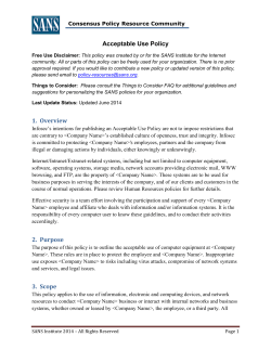
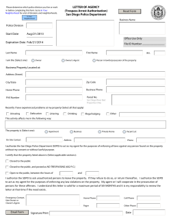
The Architectural Advantages of HP P4000
SANs
Achieve linear scalability, high availability, multiple layers
of reliability, efficient use of IT resources, scalable and
manageable performance, and integrate with applications to
provide an advantage over traditional storage architectures
Technical white paper
Table of contents
Executive summary............................................................................................................................... 2
Keeping up with new demands on storage systems .................................................................................. 2
Meeting the challenges with a superior architecture ............................................................................. 3
Key features of HP P4000 SANs ........................................................................................................ 4
Scalable capacity and performance ....................................................................................................... 8
Online, linear performance scaling with Network RAID ...................................................................... 10
Scalable management .................................................................................................................... 13
High availability ................................................................................................................................ 13
High availability with the Multi-Site SAN ........................................................................................... 14
Increasing availability with iSCSI load-balancing and MPIO ............................................................... 15
Multiple layers of reliability ................................................................................................................. 17
Efficient use of IT resources ................................................................................................................. 19
Application integration ....................................................................................................................... 23
Integration with Microsoft applications ............................................................................................. 23
Integration with VMware vSphere software ....................................................................................... 24
API and CLI integration ................................................................................................................... 25
Scalable and manageable performance ............................................................................................... 26
Conclusion ........................................................................................................................................ 29
Executive summary
HP P4000 Storage Area Networks (SANs) are clustered iSCSI SANs that support virtualized and nonvirtualized environments alike. The product line has a comprehensive feature set that includes all of its
sophisticated storage management. This white paper illustrates how the key features and architecture of
P4000 SANs contribute to the product’s superior scalability, high availability, reliability, efficiency,
application integration, and its high performance.
Keeping up with new demands on storage systems
The rapid evolution of server technology has left many administrators unprepared. Powerful systems
based on multi-core processors such as HP ProLiant servers speed even the most intensive workloads,
placing greater demands on storage performance and throughput. Today, the traditional rules of
thumb that suggest how much storage capacity and performance to allocate per server are no longer
sufficient. In virtualized environments, the challenge is further compounded: virtualization increases
server utilization levels, which further increase the demand for storage performance. Virtualized
environments are also more dynamic, and the ease with which server administrators can create new
virtual machines (VMs) poses further challenges. Failure to keep up with new server technology and
virtual environments can make the investment in these technologies painful. Subsequently, the
demands placed on your storage systems include:
• Higher efficiency: The need to trim operating expenses, while increasing availability is driving
the move toward virtualization. Deploy more applications, with better performance,
while using less of the data centers’ limited space, power, and cooling resources.
Storage administrators are facing the same pressures, yet some storage architectures are inefficient
and force IT organizations to purchase space for future needs at the time their systems are
deployed—a costly proposition in the face of limited budgets. Server virtualization may help
dramatically reduce costs, but those savings are lost on overspending for underutilized storage.
• High availability: As virtualization vendors offer high availability options that eliminate the host
server as a single point of failure (SPOF), it is important to understand the storage implications this
introduces. Those VMs that are now highly available must reside on shared storage. The question
now becomes, “Is the shared storage at least as resilient, and can it provide continuous availability
across the same scope of failures?” If not, the VM’s single point of failure is the storage on which it
is stored. Highly available storage is critical for comprehensive real-time VM protection.
• Flexibility: Virtualized environments remove server purchases from the application deployment
process, making it easy to roll out new applications, test and development environments, and scale
existing applications. The ease of creating VMs challenges the old way of doing business in
storage. In the past, storage systems and SAN interconnects were configured only as physical
servers were commissioned and decommissioned. Now the proliferation of VMs demands storage
systems that can manage storage volumes as easily as VMs can be created, cloned, moved, and
deleted.
• Performance: Workload consolidation through virtualization helps to increase system utilization.
Server workloads can now reach up to 85 percent—placing a correspondingly higher demand on
storage performance. Additionally, since spinning up new VMs is so simple, the impact on storage
is often overlooked. Careful consideration needs to be paid to storage performance that can scale
and meet the unique requirements of server virtualization.
To watch the demo of StorageWorks P4000 G2 SAN Solution click here:
http://h71016.www7.hp.com/html/interactive/p4000g2/model.html?buyNowLink=noshow&quickspecs=defau
lt&jumpid=re_r2515_3d/STO/p4000g2/ProdPage/flash/COMM/NonIDP
2
Meeting the challenges with a superior architecture
HP P4000 SANs respond to the demands of next-generation data center workloads. Based on scaleout architecture, P4000 SANs complement advances in server and virtualization technology with highly
efficient, fault-tolerant, flexible, and high-performance storage solutions:
• Efficiency is improved by enhancing storage utilization levels and using a scale-on-demand model
that allows organizations to better align storage costs with limited budgets. P4000 SANs increase
storage utilization through thin provisioning and deduplication technology that is built into every
SAN. The pay-as-you-grow model reduces the need to over-purchase storage for future needs by
allowing storage to be purchased only as it is needed.
• High availability, fault tolerance, and disaster-recovery features enable companies to take full
advantage of the corresponding features that server virtualization solutions offer. P4000 SANs
provide high data availability with automatic failover and failback that is transparent to
applications. This allows the VM that resides on P4000 SAN to be as resilient as the servers that
host them. The solutions incorporate support for disaster recovery that helps automate geographic
failover while reducing failback time. And nearly every operation you can perform on a volume or
a cluster—from changing a volume’s RAID settings to replacing an entire storage node—can be
done without taking storage volumes or the applications that use them offline.
• Flexibility to keep up with rapidly changing server configurations is provided
through features that complement the capabilities of virtualized environments—
including the ability to instantly create, copy, move, clone, and modify storage volumes through a
single, centralized management console. P4000 SANs go wherever your Ethernet network reaches.
The use of iSCSI technology—SCSI over standard Internet Protocol (IP)—reduces costs and helps IT
organizations to realize the vision of connecting every server to high-performance storage.
• Performance and capacity scale simultaneously, without disruption, making P4000 SANs a solution
that can meet the dramatically increased performance demands of multi-core servers and virtualized
environments unlike many other storage solutions. Managing performance is streamlined, and
troubleshooting complex virtualized environments is simplified, through a Performance Management
System that provides relevant performance statistics for the context being examined, from VM to
individual storage node performance.
P4000 SANs meet today’s storage challenges with a scale-out architecture based on storage
clustering—a set of storage nodes in which every node participates equally in sharing both the
workload and the storage capacity of the cluster. Storage nodes are based on proven HP
ProLiant technology, and they work together to make logical volumes available to
application servers (See Figure 1). The cluster operates as a single system aggregating the
storage, processing, and connectivity resources of each of its storage nodes. P4000 SANs provide
virtualized, block-level storage that interoperates with other products in the HP storage family
including deduplication, virtualized tape, and virtualized file storage products.
3
Figure 1: HP P4000 SANs are built from enterprise-class HP servers where the physical blocks corresponding to virtual volumes
are distributed evenly across the cluster.
Each storage node runs its fully featured storage software on proven HP ProLiant systems equipped
with either SAS or Midline SAS (MDL-SAS) disk drives, CPUs, cache, and RAID controllers. The
storage software manages each storage node and it allows them to work in concert with the other
nodes in the cluster. The resulting storage product offers greater efficiency, higher availability and
fault tolerance, more flexibility, and improved performance compared to many purpose-built storage
devices.
Key features of HP P4000 SANs
Five key features of P4000 SANs form the foundation that enables them to provide highly
scalable, available, reliable, and efficient high-performance that is easy to integrate with applications
and to manage.
For the podcast: Listen to Chris McCall who talks with HP Storage Guy Calvin Zito about what’s
new with the HP StorageWorks P4000 SAN solution:
http://h30431.www3.hp.com/index.jsp?rf=sitemap&fr_story=ba210cd42d101ca53222cea9d613aebc78092
8d1&jumpid=reg_R1002_USEN
Storage clustering
P4000 SANs are based on n-way storage clustering, not a traditional two-way active/active or
active/standby configuration than has inherent performance limitations. Storage clustering aggregates
the resources of a set of storage nodes into a single, dynamically scalable pool of resources where
every element in the cluster contributes to both capacity and performance. Storage clustering
provides a grow-on-demand model where nodes can be added to the cluster as
needed, without disrupting application availability. P4000 SANs are designed to have no single
point of failure, with the ability to recover from errors gracefully and without human intervention.
4
Network RAID
Network RAID provides built-in synchronous data protection with automated failover and failback,
across an entire storage cluster. Network RAID is configured on a per-volume basis, and dictates how
a logical volume’s blocks are laid out across the cluster, providing reliability that can be configured to
best meet application and data requirements. P4000 SANs provide two distinct types of Network
RAID. Using a minimum of two storage nodes, Network RAID 10 synchronously replicates copies of
each of the volume’s data blocks so they exist on two nodes in a cluster. The volume is guaranteed to
have two copies of every block available. Network RAID 10 provides two copies by default, but for
data that provides even higher levels of availability, 10+1 (3 copies) and 10+2 (4 copies) are also
available. Network RAID 5 is the stripe + parity option, and provides better capacity utilization than
Network RAID 10. For volumes that don’t require the performance that Network RAID 10 provides,
Network RAID 5 is an excellent option. Additionally, Network RAID 6 provides dual parity protection.
Network RAID is a per-volume attribute, so changing a volume’s RAID level is a simple operation that
does not cause any interruption in service.
Thin provisioning
Thin provisioning efficiencies underlie every SAN function, including snapshots, remote copy, volume
migration, and asynchronous replication, providing excellent capacity utilization. With the P4000
SAN you can set a per-volume attribute that determines whether a volume’s blocks are preallocated
(full provisioning), or are only allocated as data is written (thin provisioning). What makes our thin
provisioning feature unique is that it is enabled with one click, and allows volumes to grow only as
data is written to the volume in small 265 KB increments. By only allocating capacity only as it is
needed, P4000 thin provisioning reduces the need for the wasteful 100 percent reserve required by
many traditional storage architectures, thus helping to raise utilization levels, efficiency, and return on
investment (ROI)—all while reducing energy consumption and carbon footprint. Thin provisioning,
combined with the ability to scale storage clusters dynamically, allows companies to purchase only
the storage they need today, and add more storage to the cluster as application data grows. This
enables IT expenses to track actual storage use closely, and it does away with the traditional model of
purchasing storage for both today and future use when a storage system is initially purchased. This
also allows organizations to take advantage of continually falling storage costs.
5
Snapshots and clones
Snapshots provide instant, point-in-time volume copies that are readable, writeable, and mountable
for use by applications and backup software. What makes P4000 Snapshots unique is that they are
thin-provisioned volume copies that require no space reservation, allowing more efficient use of
storage. They can help to prevent the almost 80 percent of data loss due to human error by allowing
multiple, point-in-time copies of a volume with the ability of instantly rolling back to a known point in
time via volume rollback. Because P4000 Snapshots are thin provisioned, companies can make
numerous snapshots of a volume over time and only the changes are committed. Snapshots can be
created manually, scheduled, scripted, and created through programmable application programming
interfaces (APIs) (See Figure 2). Built-in application integration provides automated quiescing for
Microsoft® Volume Shadow Copy Services (VSS) applications, such as Exchange, SQL, File Systems,
SharePoint, and Hyper-V.
The SmartClone feature uses the snapshot mechanism to clone volumes instantly for use by virtual or
physical servers. The feature turns any volume or snapshot into one or many full, permanent, readwrite volumes. Volume clones use copy-on-write semantics to avoid copying or duplicating data,
making SmartClone an instant, space-efficient mechanism that also helps increase storage utilization
and improve storage ROI. SmartClone makes it as easy to create a new volume copy as it is to create
a new VM to use it, making the feature an ideal companion to VM cloning features. The
SmartClone feature helps companies respond quickly to changing business
conditions, create new VMs for development, test, or deployment purposes, and make virtual
desktop environments efficient, secure, and cost-effective.
Figure 2: Snapshots are instant, point-in-time volume copies that can be mounted and used to support temporary servers and
VMs, and for backup purposes.
6
Disaster recovery
HP P4000 Remote Copy provides time and space-efficient asynchronous replication for disaster
recovery and backups. It supports one-to-one, one-to-many, many-to-one, and round robin
configurations, which allow it to meet today’s disaster recovery (DR) needs. Remote Copy is based on
thin-provisioned Snapshots that allow for precise, instant, point-in-time volume copies (Figure 4). It
creates a remote, space-efficient replica of a snapshot, on the local cluster, and utilizes only the space
allocated for changes on the remote cluster (See Figure 3, Steps 1 and 2). The asynchronous
replication is simply a series of scheduled remote copies that support the same application integration
as standard snapshots. A P4000 SAN understands the relationship of any remote copy to the sync
point on the primary copy, so only the blocks that have changed since the last remote copy are
asynchronously replicated (See Figure 3, Step 3). This simplifies failover for DR, because there is no
issue regarding incomplete or inconsistent writes. It makes failback an efficient process because only
the incremental, changed data blocks must be copied back to the primary location once service has
been restored. Remote copies are space-efficient, and custom bandwidth management helps to share
wide-area network (WAN) resources and maintain network quality-of-service levels. Additionally, if for
any reason the replication was interrupted, it would continue from the last tenth percentile completed
as soon as possible.
Figure 3: Remote Copy uses space-efficient, thin-provisioned snapshots to create consistent, point-in-time copies for centralized
backup and disaster recovery.
7
Centralized management
The Centralized Management Console (CMC) makes the everyday operation of P4000 SANs simple
and worry free. Provided with every P4000 SAN, it provides a single point of management for all
SAN features. No matter how many P4000 SANs an organization installs, local or remote, they can
all managed through a single, intuitive, graphical user interface (GUI). It takes the complexity out of
SAN management by making it as easy to manage one cluster as it is to manage many, regardless of
the size. It simplifies management operations, for example provisioning a volume, changing its
attributes, copying volumes, or taking snapshots, by making them easy-to-execute tasks. Figure 4
illustrates how key volume attributes including cluster location, Network RAID level, replication
priority, volume type, and full or thin provisioning can be set in one central location.
For complex operations such as geographic failover and failback, the CMC provides wizards to take
the risk out of performing critical functions in time of stress. It provides access to all the information
needed to manage a SAN, including capacity planning and storage utilization information that can
be viewed on screen or exported for use in presentation or trend analysis spreadsheets.
Best practice configuration
The Best Practice Analyzer continually monitors the SAN to make sure that P4000 best practices, such
as cluster size, disk raid consistency, and Network Interface Card (NIC) bonding configurations are
adhered to. The data is always displayed on a dashboard in the CMC, and that will inform you as to
what changes need to be made. This is a proactive approach to increasing the overall SAN
experience.
Scalable capacity and performance
Scalability means that adding more resources to a system results in a commensurate increase in the
system’s ability to perform work. The P4000 is a scale-out architecture, which delivers storage that
scales in both capacity and performance linearly, all without disrupting data access. Consider the
P4000 SAN to be a single pool of storage resources comprised of building blocks, which are the
storage nodes. Each storage node contributes its own disk drives, RAID controller, cache, memory,
CPU, and networking resources to the cluster. Every volume is striped across each node in the cluster,
thus leveraging all of their critical resources. The storage software manages each storage node in
parallel, so the cluster’s performance increases in lock step with its storage capacity. This means that
when you add nodes to a cluster, you get both the performance and capacity to meet your needs.
This contrasts to the traditional methods used by most other SANs and some network attached storage
(NAS) appliances that consist of purpose-built controllers and disk trays (See Figure 6). These systems
scale by adding disk trays, increasing performance only to the point at which the controller or the
Fibre Channel interconnects becomes a bottleneck. At that point, organizations must either upgrade to
higher-power controllers or add new storage systems. Either choice can result in significant amounts of
application downtime.
8
Figure 4: P4000 SANs use storage clustering to scale capacity and performance simultaneously and non-disruptively.
9
Figure 5: P4000 SANs maintain a constant ratio of processing resources (RAID controllers, cache, memory, and CPU) to disks,
helping them to deliver linear scalability. This contrasts to controller-based architectures that scale until the controllers become a
bottleneck and performance levels off or declines.
Online, linear performance scaling with Network RAID
Online, linear performance scaling is made possible through a highly parallelized architecture, and
the combination of storage clustering and Network RAID makes this possible. Network RAID spreads
the SAN’s data across the cluster’s storage nodes so that they can work in parallel to satisfy
application server data requests. Specifically, it stripes and replicates data blocks across the cluster as
dictated by the cluster’s size and each volume’s availability requirements. For example, a volume with
a Network RAID level of 0 is a simple stripe of data blocks and has no data replication. The volume’s
blocks are laid out sequentially across all of the cluster’s nodes (See Figure 7) in a predictable order.
A volume with Network RAID 10 stripes and replicates the data blocks so that a copy of every block
is stored on two separate nodes in the cluster.
10
Figure 6: Network RAID 10 can mirror up to four copies of each data block across a storage cluster. A volume’s block layout
for Network RAID 0 (no replication) is shown on top, with the block layout for Network RAID 10 (two copies of every block)
illustrated on bottom.
11
By leveraging storage clustering and Network RAID, P4000 SANs can scale capacity and
performance while remaining online. When one or more new storage nodes are added to a cluster,
Network RAID rearranges the striping and replication scheme for the volumes to include the new
nodes. Unlike traditional storage products, P4000 SANs can do this while remaining online, with
scaling completely transparent to application servers. From the application server point-of-view, a
volume is connected via a single iSCSI session, or multiple iSCSI sessions if multi-path I/O (MPIO) is
being used. When new storage nodes are added to the cluster, there is no interruption in the iSCSI
session(s), thus no interruption in volume availability. Likewise, the new storage capacity is added to
the storage pool (cluster) and is available instantaneously to the application servers. Data for the
volumes stored on the cluster is migrated in the background as it rebalances the workload for high
performance and availability. This is possible because the cluster knows where every data block
resides, even during a data restriping operation.
A storage cluster of a particular size has a finite amount of performance that it can deliver to the
application servers that are connected to the cluster. In order to increase performance, simply add
more storage nodes to the cluster. For example, a storage cluster of four storage nodes (See Table 1)
has a certain number of disks, CPUs, memory, cache, and network adapters that ultimately determine
the performance that a cluster can deliver. Add two storage nodes to the cluster and the available
performance scales linearly because available performance resources have increased by 50 percent.
Add four more nodes and the cluster performance increases nearly 100 percent. The storage
clustering technology dynamically restripes data for all the cluster’s volumes across the existing and
new storage nodes, thus increasing the available performance of those volumes on the storage cluster.
Table 1: Resources available in 4-, 8-, and 16-node P4500 SAS clusters
Performance attribute
4-node cluster
8-node cluster
16-node cluster
Disks (12 disks per node)
48
96
192
CPUs (1 CPU per node) and
Cores (4 cores per node)
4 CPUs, 16 cores
8 CPUs, 32 cores
16 CPUs, 64 cores
RAM/Cache (4.5 GB per
node)
18 GB
36 GB
72 GB
Network bandwidth with
dual 1 or 10 Gigabit
Ethernet interfaces per node
8 Gbps/40 Gbps
16 Gbps/80 Gbps
32 Gbps/160 Gbps
I/O to the iSCSI target is load-balanced across all storage nodes in order to scale application server
performance. The combination of scaling the available resources in the storage cluster and load
balancing all iSCSI connections across all storage nodes allows the application servers connected to
volumes on the storage cluster to have access a larger pool of resources that can deliver greater
performance.
12
Scalable management
An often-forgotten aspect of scalability is the need for a system to scale without increasing in
complexity, especially management complexity. The CMC manages all storage clusters from a “single
pane of glass” no matter the size or location of the storage clusters. The storage cluster serves as a
layer of abstraction so that the administrator does not need to manage each storage node
individually, but rather as a single entity. Once the storage node is added to a cluster, all other
operations are performed against the storage cluster as a whole. Managing a P4000 SAN of 50
storage nodes is as easy as managing a SAN of two storage nodes. For example, adding a new
storage node to a cluster is as simple as discovering the storage node in the CMC, and assigning it to
a cluster. The management console and the cluster itself coordinate the integration of the storage
node into the cluster with no additional intervention from administrators. This allows P4000 SANs to
increase in size without increasing in management complexity.
High availability
High availability is about keeping data online and available at all times. This capability is enabled in
the P4000 SAN architecture through a combination of storage clustering and Network RAID. Storage
clustering turns a set of storage nodes into a storage pool from which volumes are allocated to
application servers. Network RAID provides high availability by synchronously protecting data across
a cluster. If any storage node is offline for maintenance, a power failure occurs, a network cable is
accidentally pulled, or other human error is the issue, a copy of the volume’s data is available from
another storage node in the cluster. By definition, the synchronous data protection performed by
Network RAID means that as application servers write data to a volume, the data is written to multiple
storage nodes based on the volume’s Network RAID Level. Network RAID 10 creates two, three, or
four copies before a write acknowledgment is sent back to the application server. This enables all
copies of the data to be identical across the storage cluster. Parity-based options, Network RAID 5
and 6 are also available. In this scheme, data is stripe plus single or dual parity. All of this is
managed internally in the cluster, and is not visible to applications.
The beauty of the high-availability architecture of the P4000 SAN is that a single storage cluster
can host volumes with different Network RAID levels, with each volume’s availability
and/or performance level matched to the needs of the application. Network RAID level is an attribute
of each volume, so it can be changed as needed without having to move a volume between RAID
groups or take it offline, as is the case with many traditional storage architectures. The result is greater
storage capacity efficiency because only the amount of storage required to support the desired
availability level is used for individual volumes. Volumes that reside on the same storage cluster can
have different Network RAID levels. For example, large files shares can be assigned a Network RAID
level of 5, for less emphasis on performance and more on capacity utilization. Alternatively, a
database volume is configured for Network RAID 10 and an enterprise resource planning (ERP)
volume might be configured for Network RAID 10+1 (three copies). Reducing the need for a number
of fixed RAID groups allows volume data to reside within the same cluster regardless of availability
level, and change on-the-fly to meet application requirements.
Storage clusters manage data layout and replication so that failover and failback is
automatic and transparent to the application servers. If a storage node goes offline,
Network RAID tracks all data that is changed on the volume since the storage node went offline.
When the offline node comes back online, the changed data blocks are restored from other copies on
the cluster or parity in the case of Network RAID 5 or 6, bringing the repaired node’s data to the
current level.
13
Likewise, from an application server’s perspective, the failover and failback of the actual iSCSI
sessions is also completely automatic and transparent. In the basic case where a single iSCSI session
for a volume is terminated on a single storage node, if that storage node goes offline, the iSCSI
session is automatically redirected to one of the remaining storage nodes in the cluster. This failover of
the iSCSI session occurs quickly enough as to not reset the session on the application server, and thus,
does not affect application server connectivity to the volume. In cases where MPIO is used for a
volume, multiple iSCSI sessions are established to multiple storage nodes in the cluster. In the event
that a node goes offline, the remaining established MPIO connections continue to support I/O for the
volume. In either case, when the failed node is brought back online, new sessions begin to be
established to that node automatically.
Figure 7: The Edit Volume dialog box provides one simple interface where Network RAID can be changed
High availability with the Multi-Site SAN
The synchronous replication capability of Network RAID 10 that protects a cluster from a node failure
also provides real-time site protection for data centers with the Multi-Site SAN feature.
The Multi-Site SAN feature includes the ability to assign storage nodes in the cluster
to different sites (racks, rooms, buildings, and cities). Based on this assignment, the
software intelligently makes the appropriate configuration and operational decisions to always protect
data from a complete site failure—all automatically. Using the CMC, an administrator can map the
data center configuration into the SAN to completely automate all site-dependant data availability
and fault tolerance decisions within the software. The CMC enables fault tolerance programmatically,
and does not allow the administrator to create a non-fault tolerant configuration.
As Figure 8 illustrates, blocks are replicated so that servers 1 and 3 can go offline without affecting
availability of any volume at Location 2. This is particularly useful in virtualized environments, where
the VMs running on Servers A and B could failover in Location 2 following such a failure. Because the
volumes are exactly the same whether accessed from Location 1 or 2, no reconfiguring of logical unit
numbers (LUNs) needs to take place in order for restarted servers or VMs to continue operations at the
alternate site.
When the failed site comes back online, its storage nodes automatically obtain any changed data
blocks so that failback is automatic and transparent to the application servers. With traditional
storage architectures, this failback process can be time-consuming, error-prone, and it can require
application downtime.
The Multi-Site SAN feature supports other more advanced networking architectures in a multi-datacenter environment. Storage clusters can span multiple IP subnets so that the storage pool can span
more complex multi-site network topologies. For each subnet and site pair, the storage cluster is
accessed using a dedicated virtual IP addresses (VIP) for iSCSI high availably in each site.
14
Application servers in Location 1 access volumes through the VIP for Location 1, while application
servers in Location 2 access volumes through the VIP in Location 2. This per-site, automatic I/O path
preferencing enables the application servers to be connected to the storage nodes that are located in
their same site.
Figure 8: Multi-site SAN configurations support continuous availability in the event of a site failure. When the downed site
returns to an online state, the data rebuild is automatic. This feature is particularly useful in virtualized environments where
server virtualization software implements server failover and requires automatic failover of underlying shared storage.
Increasing availability with iSCSI load-balancing and MPIO
Every P4000 SAN is enabled for high availability iSCSI data path operations by simply including at
least two storage nodes in a cluster. There are two connection methods for volumes on the SAN. By
default, all volumes are enabled for iSCSI load-balancing connection for the application servers.
Alternatively, for even higher levels of connection availability, organizations can implement MPIO,
with specific optimizations for Microsoft Windows® and VMware vSphere environments.
15
By default, a P4000 SAN load balances all iSCSI sessions (via iSCSI login redirect) from client iSCSI
initiators across all the storage nodes in the cluster, and then processes all subsequent data I/O
requests from that client through that same node. The storage node then redirects each client request
to the storage node owning the desired data block, and then redirects the response back to the client.
In the event that a storage node hosting the iSCSI session for the volume goes offline, the iSCSI
session is automatically redirected to one of the remaining storage nodes in the cluster. This failover of
the iSCSI session occurs quickly enough so that the session on the application server does not reset.
This avoids having an impact on the application server’s connectivity to the volume.
The P4000 device-specific module (DSM) for the Microsoft Windows MPIO iSCSI plug-in contributes
to availability in two ways. First, it establishes independent iSCSI sessions from the application server
to each storage node in the cluster for the volume, thus establishing multiple I/O paths for the volume
that can all be used concurrently. In the event a node goes offline, the remaining established MPIO
connections continue to support I/O for the volume. Second, when the failed node is brought back
online, the DSM for MPIO will automatically reestablish MPIO sessions to the restored node.
Also, the DSM for MPIO knows the layout algorithms for the storage cluster. It can thus calculate the
location of any block in any virtual volume. Knowing which server contains the desired block allows
the iSCSI driver to contact the storage node that owns the block directly, without the redirection used
by the standard iSCSI load-balancing approach. Figure 10 illustrates a redirected login sequence, the
SCSI Mode Sense command that loads the cluster-specific information into the driver, and the
separate I/O path that the driver establishes to each server in the cluster.
16
Figure 9: The P4000 SAN’s device-specific module for the Microsoft MPIO driver (MPIO DSM) increases performance and
availability by establishing parallel I/O paths—one to each storage node in the cluster.
Multiple layers of reliability
While high availability makes data available anywhere, reliability is about protecting against data
loss. This is a challenging proposition given the forward march of disk technology that continually
increases disk density. Today, disk reliability is expressed in terms of bit error rate (BER), reflecting the
fact that disks fail as a function of the amount of data read or written, not time. As disks increase in
capacity, they are more likely to fail when read from beginning to end; this is exactly what happens
during a RAID array rebuild after a single-disk failure in a traditional storage architecture. RAID alone
is no longer sufficient to protect against the loss of online data.
P4000 SANs provide multiple layers of protection against data loss built into the architecture. Multifault protection protects against data loss due to the failure of any single component in a storage
node, and it protects against the failure of multiple components across storage nodes.
• Reliability begins with the use of enterprise-class server technology from HP in storage nodes. Each
storage node is built with dual power supplies, dual 1 Gigabit Ethernet NICs and/or one dual-port
SFP+ 10 Gigabit Ethernet NIC, built-in disk RAID, and battery-backed write cache, all of which
contribute to data protection. Depending on the system and the organization’s requirements, disk
RAID levels 5, 6, and 10 can be configured on each storage node and then combined with
Network RAID across the storage nodes to protect against multiple concurrent component failures.
17
• Network RAID adds dual-fault protection to P4000 SANs by protecting against multiple component
faults that can take one or more storage nodes offline. By storing multiple copies or parity protected
copies of a volume’s data across the storage cluster, volumes can be configured for very high
reliability levels where multiple failures in the SAN can be tolerated while still having access to the
data. Given the multiple layers of data protection, multiple concurrent component failures including
disks, network interfaces, power supplies, and cabling do not affect the ability to access a volume’s
data. For example, a single disk can fail in every node in a cluster and the storage node’s internal
hardware RAID will continue to make the data available. Network connectivity can fail and the
redundant links to other storage nodes can continue to provide access to the data. Entire storage
nodes can fail and the data is still available for volumes protected with Network RAID 5, 6, or 10.
Combinations of disk and Network RAID levels can be configured to best meet the organization’s
performance and reliability goals. Disk RAID levels 5, 6, and 10 can be configured on each storage
node and then combined with Network RAID levels to achieve extremely high reliability levels along
with the ability to operate continuously even across two or more failures. Table 2 illustrates these
trade-offs and the number of simultaneous disk failures the SAN can withstand without any data loss.
The default is a combination of hardware RAID level 5 on each storage node with Network RAID 10,
which can withstand more than two faults.
Table 2: Organizations can combine hardware and Network RAID levels to achieve the balance of performance and reliability
characteristics most appropriate for their applications.
18
• For added data protection, space-efficient snapshots can be used to create point-in-time copies of
data for backup purposes. Snapshots can be created as needed, on a schedule, or synchronized
with application state to create a stable, consistent point-in-time copy for use as an instant backup
or as a source for tape backup or remote copy. Snapshots help to recover from issues including
software-caused data corruption, logical file system problems, and accidental or malicious
destruction of data. Snapshots can be used to restore entire volumes through a simple rollback
process. They can be used to restore individual files because, unlike many other SAN products,
snapshots can be mounted and individual files retrieved from them.
• Remote Copy provides space and bandwidth-efficient asynchronous replication, further increasing
the protection that P4000 SANs give to business-critical data. Remote copies are consistent, pointin-time copies of data stored at a remote location that can be used to continue business operations
at an alternate site in the event of a geographic failure. Remote copies also can be used to
replicate data for centralized backup.
Efficient use of IT resources
Improving storage efficiency begins with an architecture that integrates efficiency strategies
throughout the entire product. The P4000 SAN architecture increases storage utilization by allowing
storage to be purchased only as it is needed, helping to track storage expenses with storage use.
Once purchased, storage is more fully utilized because P4000 SANs use thin provisioning
throughout, reducing the need to hold large amounts of storage in reserve. Efficiency in P4000 SANs
goes beyond just the storage system: it also helps to make more efficient use of IT resources such as
local-area and wide-area network bandwidth.
• Pay as you grow: The storage clustering architecture combined with Network RAID allows the
capacity of the SAN to grow over time, without disrupting application availability. This allows
companies to purchase only the storage they need today, and then purchase more storage only as
it is needed. This “pay-as-you-grow” architecture stands in sharp contrast to traditional storage
architectures where all of a SAN’s storage must be purchased upfront. Instead, organizations can
purchase storage in affordable increments rather than having to justify the purchase of future
storage today. This model makes even more economic sense as drive prices tend to decrease over
time. Storage nodes purchased months from now could cost even less than today.
• Storage efficiency through thin provisioning: In P4000 SANs, thin provisioning is a
feature that is integrated throughout the architecture, allowing all storage for volumes, snapshots,
remote copies, and volume clones to use only the storage they need. This helps to increase storage
utilization and reduce total cost of ownership. The thin provisioning engine only allocates storage
from the storage cluster as data is written to the volume (snapshot, remote copy, or clone) to be
perpetually optimal for storage capacity utilization. By default, all snapshots, remote copies, and
clones are always thin provisioned, doing away with the need for the administrator to manage the
storage reservations for those items. Thin provisioning allows volumes to be sized large from the
beginning with no impact on cost because no storage is actually allocated when the volume is
created. This approach, commonly known as “over-provisioning” allows the administrator to present
more capacity to the application servers than is actually in the storage cluster. As storage volumes
have blocks allocated to them and the storage cluster begins to fill to capacity, additional storage
nodes are purchased and added to the storage cluster. The storage pool capacity grows
underneath those volumes with no impact to application availability.
19
• Deduplication with SmartClone volumes: When volume copies are created to support new
virtual machines, test and development environments, and virtual desktop environments, there is no
better efficiency than sharing existing data and eliminating the need to store multiple copies of
every volume. SmartClone volumes are a deduplication strategy for volume copies where
duplication is avoided from the beginning. Instead, SmartClone volume copies are created as thinprovisioned volumes with copy-on-write semantics where the cloned volume simply points back to
the original volume. This allows each volume clone to share blocks from the original volume up until
the point where a block is modified by an application server and made unique. Then, and only
then, is an actual storage block allocated to the SmartClone volume and then data updated on
the volume.
• NAS Gateway for file and print services: HP StorageWorks P4000 Unified NAS Gateway
boosts the value of P4000 SAN environment by adding Windows-powered IP-based gateway
services with Windows Storage Server 2008 R2. The operating system is preinstalled, providing
a fast, safe, and easy way to add gateway services to a P4000 SAN. Since the P4000 Unified
NAS Gateway can be clustered for high availability, both host and storage are protected.
Single Instance Storage (SIS) recovers up to 35% of disk capacity by reducing the number of
redundant files.
• Deduplication with HP storage products: Two products from HP contribute to even greater
efficiency through additional layers of deduplication technology that allows organizations to get
more capacity out of their P4000 SAN:
– HP P4000 Unified NAS Gateways provide network file storage for Microsoft Windows operating
systems and can use P4000 SANs as their back-end storage technology. This storage appliance
increases storage efficiency by reducing data duplication at the file level. This Microsoft
Windows Single Instance Storage (SIS) stores only one instance of each file.
– HP D2D Backup Systems with HP StoreOnce deduplication technology provide secondary storage
for disk-to-disk backups, offloading the data from the primary P4000 SAN. The D2D Backup
Systems feature HP Dynamic deduplication that can retain up to 50 times more data on the same
disk providing efficient storage and fast restore, enabling low bandwidth replication over a
WAN for cost-effective off-site backup and recovery.
• Efficient use of storage in remote copies: The integration of thin provisioning with Remote
Copy results in highly efficient use of storage for disaster recovery. In a P4000 SAN, the primary
volume is always thin provisioned. The snapshot that initiates the remote copy is created without
reserve, and the remote copy is also thin provisioned (See Figure 10). The remote copy requires the
same exact number of blocks be allocated on the local and the remote site: the number of blocks
that are actually in use. For example, if a volume is 40 percent utilized on the primary site, the
remote copy of the volume in the remote site requires only 40 percent capacity utilization in order
to establish the remote copy between sites. Contrast this to a traditional storage architecture where
a 100 percent reserve is typically required for a local snapshot, a 100 percent reserve is required
for the remote copy, and the remote copy itself must be copied before it can be mounted and used
at the remote site (See Figure 11).
• Efficient use of network bandwidth: Remote Copy manages the remote bandwidth that it
uses for copying data between sites so that precious WAN resources can be shared efficiently with
other network services. The P4000 manages remote copies so that the bandwidth they use does not
exceed preset limits. If network conditions deteriorate for any reason, Remote Copy automatically
adapts its packet flow to accommodate, without requiring complex network quality-of-service
management.
Remote Copy further conserves bandwidth by check-pointing in-flight remote copies at every 10th
percentile of the journey. If a network interruption occurs during a remote copy operation, it can
resume from the checkpoint rather than having to restart at the beginning. This strategy also helps to
reduce the disruption in the event of an interruption in network connectivity.
20
Within a cluster, local network bandwidth can be prioritized for peak storage response times for
applications by setting a lower priority for activities such as data rebuilding or restriping.
Figure 10: P4000 SANs require only two copies of volume data for remote copies—a savings that is amplified because remote
copies and snapshots are thin provisioned.
21
Figure 11: Traditional storage architectures require three copies of data when remote copies are created. The wasteful use of
storage is compounded by the lack of thin provisioning.
22
Application integration
Storage is ultimately about supporting applications, and applications are supported best when
storage functions are integrated with application software. Risk is reduced when application data is
backed up at a point in time when it is in an application-consistent state. Performance and reliability
is increased when knowledge of the iSCSI SAN is extended into the operating system. Business agility
can be increased when storage features match those of virtualization software—and creating new
storage volumes, or clones of existing ones, is as easy as creating new virtual machines. Costs can be
reduced when a virtual SAN recruits orphaned storage for use. Business continuity can be achieved
when storage failover and failback is coordinated with the virtual machine failover and failback. And
automating IT best practices through custom software and scripts is made easy with Command-line
interfaces (CLIs) and APIs that allow storage functions to be programmed along with other IT functions
such as server provisioning.
Integration with Microsoft applications
P4000 SANs are certified for interoperability with Microsoft applications including Microsoft
Exchange, Microsoft SQL Server, Microsoft SharePoint, and Microsoft Hyper-V.
Storage management for Microsoft Windows applications
Integrated into the architecture of every P4000 SAN is the ability to manage all the cluster’s storage
features from the standpoint of a Windows application. The storage management functions are tightly
integrated with the storage management functions of Microsoft Windows applications. For example,
Thin Provisioning, Snapshot, Remote Copy, and SmartClone features are integrated with Windows
applications such as Exchange, SQL, SharePoint, Hyper-V, and file sharing. As an administrator
manages a P4000 SAN through the CMC and performs tasks that require integration with the
application, the storage software automatically initiates the appropriate application server API calls
as part of the SAN management function. For example, if the administrator creates a remote copy of
a Microsoft Exchange database volume, the storage cluster communicates with the VSS API
framework to request a consistent snapshot to be created of the both the database and log volumes
(as a consistency group), create the snapshots, and then remote copy the snapshots to the other site.
The linkage between the Windows application servers and the storage cluster is made through the
Windows Solution Pack, so the SAN is now application-aware for Microsoft Windows applications.
There is no additional management server or user interface required to drive this Windows
application integration with P4000 SANs.
Volume Shadow Copy Services (VSS) Integration
The VSS Provider for Windows coordinates the creation of snapshots for backups with the
Microsoft applications, creating consistent, point-in-time copies of volumes (See Figure 12). The instant
nature of P4000 Snapshots means that backups coordinated through VSS have low impact on
application response time. Consistency groups guarantee that multiple volumes are all captured at the
same time so that application data spread across volumes is always backed up consistently.
Requestor functions are included that extend the capabilities of the VSS Provider to create applicationmanaged snapshots. Application-managed snapshots use VSS to quiesce VSS-aware applications
before creating the snapshot. VSS integration also supports Microsoft Windows Cluster Shared
Volumes (CSV), and can automatically quiesce CVS volumes when taking snapshots for improved
application integration.
23
DSM for MPIO
The DSM for MPIO integrates with the Microsoft Windows iSCSI MPIO framework for increased
performance and availability. The DSM establishes an independent iSCSI session between the
application server and each storage node in a storage cluster, helping to increase parallelism for
performance and availability.
Figure 12: The HP P4000 VSS provider for Windows helps coordinate snapshots of consistent application data for backups.
Integration with VMware vSphere software
P4000 SANs are certified to integrate with VMware vSphere software, and they are the ideal storage
solution for virtualized environments. Basic features, such as SmartClone volumes, make it as easy to
create new logical volume copies as it is to create new virtual machines. Advanced virtualization
capabilities such as VMware VMotion, VMware High Availability (HA), and VMware Fault-Tolerance
(FT) require the use of highly available shared storage, and P4000 SANs provide solutions for data
center and even remote and branch offices. P4000 SANs work with VMware Site Recovery Manager
to respond fast and accurately to disasters that are geographic in scope. HP participates and
demonstrates leadership in VMware’s vStorage initiative.
24
HP P4000 Virtual SAN Appliance
Virtualization provides a way for branch offices and remote offices to consolidate
their workloads onto a smaller number of servers while enjoying features—such as high
availability—that are often implemented only in enterprise data centers. To take advantage of these
features, however, requires shared storage, and the P4000 Virtual Storage Appliance (VSA) rescues
the orphaned storage devices on the virtualized servers themselves to provide a low-cost SAN using
existing hardware. Once a VSA is implemented in a remote or branch office, features such as Remote
Copy can be used to store consistent copies of remote data in a central data center. This data can be
used both for backup to HP Virtual Tape Libraries and for business continuance purposes.
HP P4000 Site Recovery Adapter
Implementing geographic failover and failback is a key component of business-continuance
strategies. Implementing them correctly can make the difference between a successful
disaster recovery and one that forces the company out of business. VMware Site
Recovery Manager (SRM) stages and executes the process of failing over to a remote site, and it can
execute a carefully choreographed sequence of which applications to bring up on which remote
servers and which order. P4000 SANs provide a Site Recovery Adapter (SRA) that works in
conjunction with SRM to be sure that remote copies are properly integrated into the failover and
failback process. This helps to make one of the most business-critical functions to execute
automatically and error free at a time that a business is most at risk.
Participation and leadership in VMware’s vStorage initiative
P4000 SANs are part of VMware’s vStorage initiative, and HP provides leadership in a number
of areas:
• Functions such as creating new virtual machines or cloning existing ones can be accomplished
through the VMware Virtual Center graphical user interface. P4000 SANs provide an API for
integrating these functions with the corresponding activities in storage. Now a virtual machine and
its storage volume can be created in one operation. Likewise, cloning an existing virtual machine
can automatically use the SmartClone feature to save time creating the volume and reducing the
space it uses.
• P4000 SANs work natively with VMware’s Pluggable Storage Architecture (PSA) for optimized
MPIO performance and availability when vSphere servers are connected to volumes on the SAN.
• VMware VAAI vStorage offloads provide the ability to offload specific VMware 4.1 and higher
tasks to the storage to improve efficiency and speed of specific workloads. For example, deploying
templates, cloning, and storage VMotion are all offloaded to the array. Also, the creation of large
virtual disks for use with Fault Tolerance (block zeroing) is offloaded to the array.
• The Virtual SAN Appliance is the first, and to date the only, certified virtual appliance for storage
on the VMware SAN Hardware Certification List (HCL). Based on this original certification, the VSA
is listed as part of the vStorage SAN Virtual Appliance (SVA) certification.
API and CLI integration
Recognizing that not all application integration needs can be met with pre-packaged solutions;
P4000 SANs provide a programmable API and a command-line interface (CLI) that allows
organizations and partners to create scripts and software to integrate storage and application
functions as needed. For example, the process of provisioning an application server might be
automated through enterprise management tools. To support the storage provisioning aspect of such
an activity, a module can be created so that all provisioning activities can be supported through a
single interface of the company’s choosing.
25
Although this section has focused on application integration for Microsoft Windows and VMware
environments, P4000 SANs integrate with any application that can access storage through an
iSCSI driver—and this includes applications running on the major operating systems running in
data centers today.
Scalable and manageable performance
P4000 SANs deliver an architecture that enables online, scalable, manageable performance that
derives from the clustered storage architecture. In contrast to traditional storage architectures, in which
performance scales only to the point where a central controller becomes a bottleneck, storage
clustering distributes the storage system’s processing so that every node in a cluster contributes to
performance. This delivers near linear scalability.
• Storage clustering: Storage clustering allows all resources in a cluster to contribute to
performance: CPUs, RAID controllers, NICs, caches, and disk spindles. As disk storage is added to
a cluster, the capacity to deliver that storage to application servers is increased as well.
• Data striping: Storage volumes are striped across all disks in a cluster, spreading out the
workload and making sure that every node in a cluster is called upon to deliver its storage with
high performance. The work of connecting to application servers is also spread across storage
clusters in the form of iSCSI load balancing.
• Multipath I/O: Microsoft Windows DSM for MPIO and VMware Pluggable Storage Architecture
MPIO increases performance by allowing independent logical connections between application
servers and storage nodes. This increase in performance significantly increases both overall
performance and the degree to which performance increases linearly with the addition of storage
nodes to a cluster. Figure 13 illustrates the degree to which the MPIO DSM for Microsoft Windows
makes performance linear with the size of the cluster.
Figure 13: MPIO DSM allows performance to scale more linearly with capacity, improving sequential I/O performance over
standard load balancing.
26
High-speed networking: Optional 10-Gigabit Ethernet connectivity to the storage nodes removes
the network as the source of bottlenecks.
Tiered storage: Tiered storage allows IT organizations to best meet application requirements while
reducing cost. P4000 SANs offer two options for storage node disk drives. High-performance 15K
RPM serial-attached SCSI (SAS) drives push performance to the limit for better price/performance
while at lower capacity. High-capacity 72K RPM MDL-SAS drives push capacity to the limit for better
price/capacity, while at lower performance than SAS drives. These two options allow storage clusters
to be optimized for performance or for capacity. Storage tiers can be established with, for example,
a cluster containing SAS drives used to support workloads with high transactional rates, and a cluster
with MDL-SAS drives used to support content-delivery systems where capacity is the most important
requirement. Once different storage clusters are created with different types of storage characteristics,
volumes can be migrated online between those clusters in order to optimize the data to the type of
underlying storage. The CMC makes migrating a volume from one storage tier to another as easy as
editing the volume and choosing the new cluster that the volume should reside on. This initiates the
live volume migration where Network RAID begins moving the data for the volume in the background.
Application servers that are connected to the volume in question, have any iSCSI sessions migrated
online from storage nodes in the original cluster to storage nodes in the new cluster. This ensures that
application server connectivity to the volume is not impacted by the migration of the volume from one
storage tier to another.
Performance Monitor: Integrated performance management capabilities are provided with
Performance Management, a feature included with every P4000 SAN and available through a single
click from the CMC. The system is designed from the ground up to make it easy to obtain the
performance metrics needed to monitor, manage, and troubleshoot storage performance, all through
a simple user interface. The Performance Monitor provides performance information at the level
appropriate for the issue at hand, helping to cut through the multiple levels of abstraction that can
make performance management in virtualized environments quite complex. For automation purposes
and data extraction into other performance management tools/suites, all the performance information
for the SAN is available via Simple Network Management Protocol (SNMP) management information
bases (MIBs) and CLI calls.
The Performance Monitor provides storage metrics based on application servers, VMs, logical
volumes, snapshots, storage clusters, and storage nodes, eliminating the wading through irrelevant
statistics in search of the ones that provide real insight (See Figure 14). The Performance Monitor’s
graphical user interface is simple and elegant, not cluttered with irrelevant and difficult-to understand
counters and statistics. Each metric is presented along with a detailed explanation of what it means
for SAN performance integrated directly into the management interface.
27
Figure 14: The Performance Management System provides performance metrics rolled up to the logical level that best helps
address this issue at hand.
Because capacity and performance scale together in P4000 SANs, the Performance Monitor can give
insight into when the time is appropriate to add storage nodes in order to increase performance. The
monitor supports trend analysis software by providing raw data and graphics for export into analysis
tools, spreadsheets, and presentations used to justify storage purchases.
28
Conclusion
Today’s more powerful multi-core servers combined with virtualization technology place
unprecedented demands on storage—demands that have not been met by traditional storage systems
that are based on controller-and-disk-tray model that has limited scalability, availability, reliability,
efficiency, performance, and ability to integrate with key business applications.
HP P4000 SANs answers these needs with an architecture that incorporates five key features
throughout the product and makes them available to every customer through an all-inclusive model.
Features including storage clustering, Network RAID, Thin Provisioning, Snapshots, and Remote Copy
form the basis for the many advantages of P4000 SANs. In addition to providing the answer to the
needs of today’s data centers, P4000 SANs are also straightforward to use and maintain through the
Centralized Management System and its integrated Performance Monitor.
Without storage systems that support them adequately, the investments that IT organizations make in
new server technology and virtualized environments can fail to live up to their promise. P4000 SANs
help these environments to realize their full potential with a storage architecture that is
better by design that provides storage features that complement the features of virtualized
environments, and that delivers linear scalability, high availability, reliability, efficiency, and
performance, and integration with business-critical applications.
Share with colleagues
© Copyright 2009, 2011 Hewlett-Packard Development Company, L.P. The information contained herein is
subject to change without notice. The only warranties for HP products and services are set forth in the express
warranty statements accompanying such products and services. Nothing herein should be construed as
constituting an additional warranty. HP shall not be liable for technical or editorial errors or omissions contained
herein.
Microsoft and Windows are U.S. registered trademarks of Microsoft Corporation.
4AA3-0365ENW, Created December 2009; Updated February 2011, Rev. 1


© Copyright 2026