
Teaching Optics with the centennial universal lantern
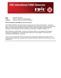
Teaching Optics with the centennial universal lantern
M. João Carvalhala, Marisa Monteiroa, Manuel B. Marques* *b
a
Museu de Ciência da Universidade do Porto, Reitoria da Universidade, Pr. Gomes Teixeira 4099002 Porto; Portugal; bFaculdade de Ciências da Universidade do Porto – DFA and INESC Porto,
Rua do Campo Alegre 687, 4169-007 Porto, Portugal
ABSTRACT
A projection apparatus was bought in 1909 by the Physics Cabinet of the Polytechnic Academy (predecessor to the
University of Porto’s Faculty of Science) in order to present various physics experiments, mostly in the realm of Optics,
to a large student audience. A stout and impressive mahogany and brass piece, with a voltaic arc lighting system, it was
manufactured by the firm E. Leybold’s Nachfölger, based in Chemnitz (Germany), already with a worldwide reputation
as a supplier of teaching instruments and equipment to superior schools and universities. It was sold along with an extensive
set of accessories, allowing for demonstrations in geometrical optics, spectrum analysis, interferometry, diffraction,
polarization and double refraction. Two extra attachments, one for projecting microscopic objects, and the other for the
projection of gypsum preparations in polarized light, added to the versatility of this lantern, appropriately dubbed of
universal use. Both apparatus and accessories are presently to be found in the collection of the Museum of Science of our
University. On studying them, we have come to the conclusion that many classical experiments in Optics may be displayed,
without great effort and in an attractive manner. The adaptation to present day usage takes no more than the replacement
of the lantern’s voltaic arc by a suitable and safer light source. It so happens that a hundred-year old projection apparatus,
fitted with a set of purposely designed add-ons, becomes so effective as its modern counterparts.
Keywords: Museum, Teaching Optics, Projection
1. INTRODUCTION
The magic lantern, whose origin is unclear (Christiaan Huyghens is credited with having built the first magic lantern around
1660) was an important piece of apparatus in the showmen’s gear by the end of the eighteenth century. With low intensity
lighting sources, the images projected were dim, which, to a certain point, explains why these shows were called
“phantasmagoria”1.
The emergence of brighter sources during the nineteenth century, such as limelight, the voltaic arc and later, the
incandescent filament lamp, enabled the use of the magic lantern in large theatre rooms, for educational purposes. The
Royal Institution and the Royal Polytechnic Institution of London resorted to them for their science lectures. Trade
catalogues of scientific instrument makers routinely show a few models, soon referred to as projection apparatus or optical
lanterns, specifically dedicated to teaching. They associate the projection of glass slides, many of them with mechanic
motion, to the ability of performing experiments of Physical and Geometrical Optics; some models comprise a microscope,
thereby replacing the solar microscope that had been used since the eighteenth century2.
By 1890, projection apparatus were already being adopted systematically as teaching aids in the natural sciences and
medicine courses. Dedicated at first to slide projection, they came to be sold with a wide array of accessories for various
purposes. Real-time experiments in Physics, Chemistry and Biology can thus be projected before large audiences, where
quantitative analysis also becomes possible through the observation of transparent scale instruments, such as thermometers
or galvanometers3.
2. HISTORY
In late 1909, the Physics Cabinet of the Polytechnic Academy of Porto - predecessor to the Faculty of Science of the
University of Porto - bought from the German company E. Leybold’s Nachfölger, based in Köln, the so-called universal
projection apparatus, with an extensive set of accessories. It was the first purchase from this company, and the choice for
*
[email protected]; phone +351 220402301; fax +351 220402437
12th Education and Training in Optics and Photonics Conference, edited by
Manuel F. P. C. Martins Costa, Mourad Zghal, Proc. of SPIE Vol. 9289, 92891I
© 2014 SPIE, OSA, IEEE, ICO · doi: 10.1117/12.2070785
Proc. of SPIE Vol. 9289 92891I-1
Downloaded From: http://proceedings.spiedigitallibrary.org/ on 05/26/2015 Terms of Use: http://spiedl.org/terms
this particular projector was made over the various projection apparatus supplied by its most direct rival Max Kohl
(Chemnitz, Germany), from whom the Cabinet had been ordering scientific instruments since 1903.
We believe that this choice may have followed a visit of a Senior Lecturer at the Physics Cabinet, Professor Francisco de
Paula de Azeredo, to Lisbon’s Polytechnic School (the ancestor of the Faculty of Science of the University of Lisbon). It
is likely that he saw the Leybold’s universal projection apparatus bought in 1907 by this School.
It is a very versatile instrument, easy to operate. Besides its normal projection function, it can be used in the demonstration
of a variety of Physics experiments, by fitting a number of accessories to the projector’s main body, rapidly and with
precision, thereby allowing for presentations in front of large audiences.
This apparatus was probably intended to be used with experiments of Physical Optics: the accessories also bought at the
time are associated with the observation of phenomena of interference, diffraction, double refraction and polarization of
light. However, experiments related to spectrum analysis, and the projection of microscopic preparations, photographs on
glass and transparent instruments, either vertically or horizontally oriented, are also possible.
The projection apparatus was then placed in the main lecture room of the Physics Cabinet, on an adjustable height stand
also supplied by Leybold (fig.1). It seems to have been used for decades: photographs taken during the 1930’s and 1940’s
let us see it in this room, always at the same place.
ai'
Figure 1. The large Physics theatre room, Faculty of Science, photo by Domingos Alvão, Porto, circa 1925 [courtesy of
Centro Português de Fotografia]. The projection apparatus is on the right, by the foremost window.
We have reasons to believe that the projector itself was not manufactured by E. Leybold’s Nachfölger. Zoller 4, on
comparing the somewhat small number of workers at the Leybold’s factory with the huge number of items listed in their
trade catalogues, states that until World War II, this company may have resorted extensively to other scientific instrument
makers, so that a significant part of their sales were actually retail sales.
It so happens that this projector is similar, in every way except for the source of light, to the one that had been advertised
by the London-based firm Newton & Co.5 since 1894. In fact, a patent with nº170596 (fig.2a), regarding a Science Lantern,
was applied for in 1893 by Herbert Charles Newton (1859-?), son of Frederick Newton (1824-1909), then owner of Newton
& Co. (H. C. himself would be running the company by 18977,8). The features described in the patent match those that can
be found in this projector: the two lenses that make up the condenser fit in separate frames, the outer one turning on
Proc. of SPIE Vol. 9289 92891I-2
Downloaded From: http://proceedings.spiedigitallibrary.org/ on 05/26/2015 Terms of Use: http://spiedl.org/terms
horizontal hinges; a rod to be fitted to this outer frame, with a rack-work on which the objective moves; and the use of a
total reflection prism that can be used also as an erecting prism. Already in 1894 a commercial ad of a new patent
“Demonstrator’s Lantern”, is published in the Optical Magic Lantern Journal, claiming to be “the most simple and efficient
Single Lantern yet constructed for general scientific work”. A similar ad can be found in manuals for lantern operators
(fig.2b).
NEWTON & CO.'S
NEW PATENT
"DEMONSTRATOR'S" LANTERN,
FOR LIMELIGHT OR ELECTRIC.
1
The most simple
and efficient
With Prism for Erecting.
and for Vertical Projection.
Pairs £10 10s.
Single Lantern
yet constructed
for general
scientific work.
3 FLEET ST.,
LONDON.
NEW CATALOGUE
ofLanterns,Projeetion Apparatus and Slides,
Post Free,
6 Stamps.
ml
é
(b)
(a)
Figure 2. (a) Drawing contained in the Patent nº17059, applied for in 1893 6. (b) Advertisement by Newton & Co., 1895 9.
The radiant perceived is limelight, also object of a patent applied for in 1894 by H. C. Newton (Patent nº12572) 10.
A few other findings contribute to this assertion: the printing stamps of some of the accessories shown in pages 109 and
113 of the “Catalogue of Physical Apparatus, constructed by E. Leybold’s Nachfölger” 11, are perfect matches of those
employed in contemporary Optics textbooks, the only difference being the absence of Newton & Co.’s signature in the
first3,9. On the other hand, it should be noted that, in the same catalogue, a few items are clearly referred to as Leybold’s
own inventions. That is the case of item number 2187, the universal arc lamp for automatic and hand feed; of the stand
with catalogue entry number 2582, and of “Leybold’s Glass Vessels for projection and other experiments”.
It is therefore possible that only the authorship of the accessories designed to perform the diverse experiments of Physical
Optics can be attributed to Leybold, as such accessories were nowhere to be found in the trade catalogues, manuals and
textbooks consulted: the same experiments were performed with the aid of different setups, or attachments, as shown, for
instance, in the contemporary Max Kohl’s catalogue12, and in both books Lewis Wright (1838-1905) wrote on the
subject3,13 (Evidence was found that Wright actually maintained collaboration with Newton & Co., while his son, Russell
Stuart Wright (1876-1961), was a business associate of Newton & Co. between 1915 and 1920 14).
3. THE UNIVERSAL PROJECTION APPARATUS
The universal projection apparatus is aesthetically a very handsome object, a stout polished mahogany body with some
varnished brass elements (fig.3). The attachments are also fine objects, made partially or completely in varnished brass,
which can be fastened to the projector with ease and accuracy.
The projector’s body is internally lined with a black metal casing, built slightly away from the outer wooden casing, in
order to keep it cool through air. This way, it will not get overheated or burnt, offering no danger to the lanternist. Access
to the lantern’s interior is provided by two side doors, with blue glass circular windows, for observation of the radiant, or
source of light (particularly in the case of limelight). Brass discs cover the circular openings during operation, while
muscovite discs fill in the corresponding openings in the metal casing. The lantern is open at the rear side, to allow in the
source of light, which used to be screened by a black velvet curtain. The space inside is adequate for the use of either
limelight or of a voltaic arc.
Holes drilled at the base of the side walls and a metallic chimney at the top ensure cooling by air circulation, allowing the
projector to work for hours at a time. The flat heated top is convenient for keeping fluids and objects warm, while projection
and experimental work takes place3.
Proc. of SPIE Vol. 9289 92891I-3
Downloaded From: http://proceedings.spiedigitallibrary.org/ on 05/26/2015 Terms of Use: http://spiedl.org/terms
Figure 3. The projection apparatus.
The condenser consists of two plano-convex lenses with the convex sides turned inwards; their diameter is 110 mm, which
enabled the projection of all glass transparencies ordinarily obtainable at the time (8,5 × 8,5 cm or 8,5 × 10 cm). The
distance they are kept apart is such that the condenser can be considered achromatic for all practical purposes (only the
boundary of the circular illuminated area is coloured). This type of condenser was the most commonly found in fine quality
lanterns in those days3.
One of the lenses is mounted on a brass garniture, at the front wall of the projector; the other one fits a wooden frame,
bound with brass, hinged to the upper part of the front so as to be turned upwards. In this way, the frame – and the
condenser’s second lens – can be placed horizontally, by sliding in, between guiding folds, a metallic plate or mirror, tilted
at 45°. Projection of experiments performed horizontally becomes possible when adopting such configuration (fig.4a),
provided that a partially or completely transparent instrument is used, for instance, for the observation of magnetic field
lines (fig.4b), of chemical reactions, etc. The addition of the total reflection prism, as coupled to the objective, enables the
projection on to a screen in front of the lantern.
Figure 4. (a) The projection apparatus prepared for experiments performed horizontally. (b) Ewing’s apparatus, where tiny
magnetic needles (now missing) on an array of pins materialize magnetic field lines.
With this configuration, it is also possible, with the help of a stylus, to make drawings, write formulae or short texts, on
small smoked glass plates, laid on the condenser’s second lens. Information that would otherwise be written on a
Proc. of SPIE Vol. 9289 92891I-4
Downloaded From: http://proceedings.spiedigitallibrary.org/ on 05/26/2015 Terms of Use: http://spiedl.org/terms
Teaching Optics with the centennial universal lantern
M. João Carvalhala, Marisa Monteiroa, Manuel B. Marques* *b
a
Museu de Ciência da Universidade do Porto, Reitoria da Universidade, Pr. Gomes Teixeira 4099002 Porto; Portugal; bFaculdade de Ciências da Universidade do Porto – DFA and INESC Porto,
Rua do Campo Alegre 687, 4169-007 Porto, Portugal
ABSTRACT
A projection apparatus was bought in 1909 by the Physics Cabinet of the Polytechnic Academy (predecessor to the
University of Porto’s Faculty of Science) in order to present various physics experiments, mostly in the realm of Optics,
to a large student audience. A stout and impressive mahogany and brass piece, with a voltaic arc lighting system, it was
manufactured by the firm E. Leybold’s Nachfölger, based in Chemnitz (Germany), already with a worldwide reputation
as a supplier of teaching instruments and equipment to superior schools and universities. It was sold along with an extensive
set of accessories, allowing for demonstrations in geometrical optics, spectrum analysis, interferometry, diffraction,
polarization and double refraction. Two extra attachments, one for projecting microscopic objects, and the other for the
projection of gypsum preparations in polarized light, added to the versatility of this lantern, appropriately dubbed of
universal use. Both apparatus and accessories are presently to be found in the collection of the Museum of Science of our
University. On studying them, we have come to the conclusion that many classical experiments in Optics may be displayed,
without great effort and in an attractive manner. The adaptation to present day usage takes no more than the replacement
of the lantern’s voltaic arc by a suitable and safer light source. It so happens that a hundred-year old projection apparatus,
fitted with a set of purposely designed add-ons, becomes so effective as its modern counterparts.
Keywords: Museum, Teaching Optics, Projection
1. INTRODUCTION
The magic lantern, whose origin is unclear (Christiaan Huyghens is credited with having built the first magic lantern around
1660) was an important piece of apparatus in the showmen’s gear by the end of the eighteenth century. With low intensity
lighting sources, the images projected were dim, which, to a certain point, explains why these shows were called
“phantasmagoria”1.
The emergence of brighter sources during the nineteenth century, such as limelight, the voltaic arc and later, the
incandescent filament lamp, enabled the use of the magic lantern in large theatre rooms, for educational purposes. The
Royal Institution and the Royal Polytechnic Institution of London resorted to them for their science lectures. Trade
catalogues of scientific instrument makers routinely show a few models, soon referred to as projection apparatus or optical
lanterns, specifically dedicated to teaching. They associate the projection of glass slides, many of them with mechanic
motion, to the ability of performing experiments of Physical and Geometrical Optics; some models comprise a microscope,
thereby replacing the solar microscope that had been used since the eighteenth century2.
By 1890, projection apparatus were already being adopted systematically as teaching aids in the natural sciences and
medicine courses. Dedicated at first to slide projection, they came to be sold with a wide array of accessories for various
purposes. Real-time experiments in Physics, Chemistry and Biology can thus be projected before large audiences, where
quantitative analysis also becomes possible through the observation of transparent scale instruments, such as thermometers
or galvanometers3.
2. HISTORY
In late 1909, the Physics Cabinet of the Polytechnic Academy of Porto - predecessor to the Faculty of Science of the
University of Porto - bought from the German company E. Leybold’s Nachfölger, based in Köln, the so-called universal
projection apparatus, with an extensive set of accessories. It was the first purchase from this company, and the choice for
*
[email protected]; phone +351 220402301; fax +351 220402437
12th Education and Training in Optics and Photonics Conference, edited by
Manuel F. P. C. Martins Costa, Mourad Zghal, Proc. of SPIE Vol. 9289, 92891I
© 2014 SPIE, OSA, IEEE, ICO · doi: 10.1117/12.2070785
Proc. of SPIE Vol. 9289 92891I-1
Downloaded From: http://proceedings.spiedigitallibrary.org/ on 05/26/2015 Terms of Use: http://spiedl.org/terms
A hand feed electric arc lamp was bought for this lantern in 1909, whose regulating mechanism is considerably simple: a
combination of three screws allows the movement of the carbons toward each other, as well as the arc to be displaced
vertically and from side to side; the catalogue itself gives some assistance on how to operate these screws suitably (fig.7),
to have the light source adequately centred. The voltaic arc lamp also has the advantage of being able to work with the
carbons either upright or tilted.
n1l@I@llallll'...
Figure 7. Different positions of the light source as shown in the maker’s catalogue 15: in “a” and “b”, it is too near the
condenser, and in “c”, it is too far from it; in “d” and “e”, the light source is respectively displaced to the right or to the left;
in “f” and “g”, it is too low and too high, respectively; “h” turns out to be the optimum position, with the circle on screen
equally illuminated. These directions are quite important when it comes to slide projection.
In connecting to a supply lead, an additional resistance was needed, as the building’s supply voltage, then 110 V, had to
be lowered down to 40 V, the voltage required by the voltaic arc. For that purpose, a set of additional resistances was also
ordered from Leybold, mounted on a marble slab switch board, equipped with a switch, lead fuses and wall plug. It also
included an adjustable resistance, with ammeter and voltmeter, to control the output current. The switchboard was lost;
only the ammeter and voltmeter remain and have been identified.
4. EXPERIMENTS IN PHYSICAL OPTICS
These experiments seem to be the main utility of this equipment. A wide range of accessories allows us to perform a variety
of experiences: interference, diffraction, polarization and double refraction of light. The elements required for each
experiment are rigidly mounted on attachments which are fastened, by means of a simple arrangement avoiding screws, to
the frame that holds the condenser’s outer lens, thereby ensuring the correct alignment of all parts.
4.1 Interference
Amplitude-splitting interferometer – this experiment, which is carried out with difficulty when mirror and slit are
separate, is performed with the greatest ease by means of this attachment, Fresnel´s mirror (fig.8), where these elements
are brought together in the same stand in front of the objective. The outcome of the experiment depends only on the
operator’s ability to achieve the adequate slit aperture, angle by which the second mirror is revolved, and position of the
lamp. When a piece of red glass is placed in front of the mirror, the wavelength of the radiation thus obtained can be
determined with reasonable accuracy.
Figure 8. Attachment known as Fresnel’s mirror: it combines a slit whose width is adjustable by a screw, a rigid stand for a
pair of mirrors, and a sliding screen in the middle. A smaller screw on the back of the second mirror controls the angle
between the two mirrors.
Proc. of SPIE Vol. 9289 92891I-6
Downloaded From: http://proceedings.spiedigitallibrary.org/ on 05/26/2015 Terms of Use: http://spiedl.org/terms
Newton’s rings – they can be observed, either in transmission (fig.9a) or in reflection; a proposed experiment consists of
limiting the observation of those rings to the central area, with a rectangular slit, and analyse their spectrum through an
Amici prism (fig.9b) or a diffraction grating.
Figure 9. (a) Attachment for the projection of Newton’s rings, with slit and Amici prism. (b) The spectra of Newton’s rings,
as obtained with the Amici prism (from Lewis Wright’s “Light: a course of Experimental Optics”, 2nd ed., 1892, plate 3 13).
4.2 Diffraction
The observation of diffraction patterns can be attained through an attachment with a slit whose aperture is adjustable by a
micrometre-screw (fig.10). Once again, a quantitative analysis is possible by resorting to coloured glass to restrain the
width of the band under analysis: the radiation wavelength can be computed out of the width of the slit and distance
between two consecutive coloured bands. A set of diffraction gratings with different constants (fig.11) further extends the
possibilities of this equipment, as far as the demonstration of diffraction phenomena is concerned.
Figure 10. Attachment for experiments on diffraction, with adjustable-width screw, and corresponding spectrum analysis
(from Lewis Wright’s “Light: a course of Experimental Optics”, 2nd ed., 1892, plate 2 13).
Figure 11. Diffraction gratings with different constants in case.
Proc. of SPIE Vol. 9289 92891I-7
Downloaded From: http://proceedings.spiedigitallibrary.org/ on 05/26/2015 Terms of Use: http://spiedl.org/terms
4.3 Polarization and birefringence
The experimental demonstration of the polarization of light is made possible with the choice of a few attachments (figures
12a, 12b and 12c). Different elements exchanging positions show that polarization can be obtained through either
absorption, reflection or birefringence. Their association and/or replacement is prompt and accurate. The same elements,
when combined with a Laurent’s quartz plate or left and right handed quartz plates, clarify how a saccharimeter works.
[1-,)
Figure 12. (a) Attachment for projection of transmitted light through two tourmaline crystals whose optical axes can be
rotated. (b) Setup for experiments on polarization, the polarizing angle (56°) being guaranteed by an auxiliary rigid arm, and
the mirror (a piece of black glass) being mounted on the attachment so as to act either as the polarizer – as in this example –
or as the analyser; (c) Attachment with two fitting rings for the polarizer and the analyser. These can be tourmaline and
calcite crystals, or nicols. Mica, gypsum and aragonite plates, etc., can also be interposed between the polarizer and the
analyser.
A polariscope ordinarily dubbed as “elbow polariscope”, because of its shape, adds to the understanding of polarized light,
having a glass pack as the polarizer and a nicol as the analyser (fig.13). This attachment is fastened to the projector and
enables the projection of images engraved in gypsum (selenite) which are, basically, preparations of gypsum with unequal
thickness. On turning the nicol, the colours pass over to their complementary (fig.14).
Figure 13. Elbow polariscope attachment and fitting procedure.
Proc. of SPIE Vol. 9289 92891I-8
Downloaded From: http://proceedings.spiedigitallibrary.org/ on 05/26/2015 Terms of Use: http://spiedl.org/terms
Figure 14. Gypsum preparation for projection in polarized light. Complementary colours as shown by the 90° rotation of the
nicol.
4.4 Projection of microscopic preparations
There is still an accessory for the projection of microscopic projections, to be attached to the projector right in front of the
condenser (fig.15a). It is designed as a composed optical microscope: a triple-lens assembly places the focus in coincidence
with the preparation, and a revolving nosepiece bears three objectives with different magnifications. As the preparations
may be damaged by the excessive heat radiating from the voltaic arc, a cylindrical trough filled with distilled water or an
alum solution is inserted between the condenser and the microscope, acting as an infrared absorption medium (fig.15b).
Figure 15. (a) Attachment for projecting microscopic objects. (b) Fitting of the heat absorption trough.
4.5 Experiments in Geometrical Optics
Using the lantern as a lighting source, it is possible to set up experiments to demonstrate the principles of Geometrical
Optics. Driving the voltaic arc lamp farther from or closer to the condenser, a parallel, convergent or divergent beam is
obtained. Accessories such as Tyndall optical apparatus (fig.16), which E. Leybold’s Nachfölger also supplied, then allow
for the demonstration of Snell’s laws of refraction and reflection, as well as of total reflection.
Proc. of SPIE Vol. 9289 92891I-9
Downloaded From: http://proceedings.spiedigitallibrary.org/ on 05/26/2015 Terms of Use: http://spiedl.org/terms
21ï-'n.
F Figure 16. (a) Arrangement of lantern and Tyndall apparatus on stand, to show reflection and refraction 15.
The Physics Cabinet did not buy any accessories for this purpose in 1909, which only confirms our conjecture that the
projection apparatus was meant for performing mainly demonstrations in Physical Optics. An attachment with arrow for
experiments in Geometrical Optics would be bought, however, later in 1912, proving that there may have been some
intention of further exploring the utility of this projector.
5. CONCLUSION
A hundred years later, this projection apparatus is still surprisingly effective and still functional: its operation depends only
on the replacement of the primitive light source by a projection lamp which is appropriate for the experiments on Physical
Optics, an approximate point source.
It is possible that an attempt of re-using it has been made in the Physics Laboratory of the Faculty of Science: in last
century’s fifties or sixties, the radiant was modified (probably at the same time the lead supply voltage was altered from
110 to 220 V); the voltaic arc’s electrodes have been replaced by two brass rods, to hold a tungsten-halogen projection
lamp, a PHILIPS 6366R, 800 W (fig.6b). However, up to this moment, no record has been found of this upgrade, nor any
memory of its working.
Self-contained and versatile, the significant number of Physics experiments that can be demonstrated through projection
would surely make it more appealing and cause a greater impact in the minds of young students than the currently used
video-projector and computer-drawn diagrams.
REFERENCES
[1] Hankins, T. L., “How the Magic Lantern Lost Its Magic”, Optics & Photonics News, January, 34-49 (2003).
[2] Hackmann, W., “Annual Invitation Lecture – Spectacular Science through the Magic Lantern”, Bulletin of the
Scientific Instrument Society, No. 116, 30-41 (2013).
[3] Wright, L., [Optical Projection, a treatise on the use of the lantern in exhibition and scientific demonstration], 4th
ed., Longmans, Green, and Co., London, New York & Bombay (1906).
[4] Zoller, P., “Physics Experiments for Everyone: German Makers”, Bulletin of the Scientific Instrument Society,
No. 102, 21-29 (2009).
[5] Holland, J., “Frederick Newton, Citizen”, Bulletin of the Scientific Instrument Society, No. 86, 24-26 (2005).
[6] European Patent Office, Espacenet Patent Search, Patent nº GB189317059, http://worldwide.espacenet.com
[7] Gee, B., “The Newtons of Chancery Lane and Fleet Street Revisited. Part I: A Question of Establishment”,
Bulletin of the Scientific Instrument Society, No. 35, 3-6 (1992).
[8] Gee, B., “The Newtons of Chancery Lane and Fleet Street Revisited. Part II: The Fleet Street Business and Other
Genealogy”, Bulletin of the Scientific Instrument Society, No. 36, 12-14 (1993).
[9] Bayley, R. C., [Modern magic Lanterns, A guide to the management of the optical lantern, for the use of
entertainers, lecturers, photographers, teachers, and others], L. Upcott Gill, London, 83-99 (1895).
Proc. of SPIE Vol. 9289 92891I-10
Downloaded From: http://proceedings.spiedigitallibrary.org/ on 05/26/2015 Terms of Use: http://spiedl.org/terms
[10] European Patent Office, Espacenet Patent Search, Patent nº GB189412572, http://worldwide.espacenet.com
[11] E. Leybold’s Nachfölger, [Catalogue of Physical Apparatus, constructed by E. Leybold’s Nachfölger, Cologne],
A. B. C. Code 5th Ed., 93-120 (190- ). This is the English version of the German catalogue prepared by R.
Bernoulli, from the distinct Bernoulli family, then the company’s resident scientist, which was published in 1904
and is commonly identified as Jubiläums-Katalog.
[12] Max Kohl, [Appareils de Physique], Catalogue nº22, Impr. Hugo Wilisch, Chemnitz (1905).
[13] Wright, L., [Light, a course of experimental optics chiefly with the lantern], 2nd ed., Macmillan and Co.,
London & New York, (1892).
[14] Lucerna – The Magic Lantern Web Resource, www.slides.uni-trier.de
[15] E. Leybold’s Nachfölger, [Einrichtungen und Apparate für den Physikalischen Unterricht sowie für Übungen
im Praktikum nebst Literaturangaben und Gebrauchsanweisungen Von E. Leybold’s Nachfolger, Cöln A. Rh.],
A. B. C. Code 5th Edition, 302-332 (1904), (Jubiläums-Katalog).
Proc. of SPIE Vol. 9289 92891I-11
Downloaded From: http://proceedings.spiedigitallibrary.org/ on 05/26/2015 Terms of Use: http://spiedl.org/terms


© Copyright 2026