
Control design for a class of nonholonomic systems via reference
Control design for a class of nonholonomic systems via reference vector fields and output regulation Dimitra Panagou∗ † Herbert G. Tanner Assistant Professor Associate Professor Department of Aerospace Engineering Mechanical Engineering Department University of Michigan University of Delaware Ann Arbor, MI, 48105 Newark, DE, 19716 Email: [email protected] Email: [email protected] Kostas J. Kyriakopoulos Professor School of Mechanical Engineering National Technical University of Athens Zografou, Athens, 15780 Greece Email: [email protected] This paper presents procedural guidelines for the construction of discontinuous state feedback controllers for driftless, kinematic nonholonomic systems, with extensions to a class of dynamic nonholonomic systems with drift. Given an ndimensional kinematic nonholonomic system subject to κ Pfaffian constraints, system states are partitioned into “leafwise” and “transverse,” based on the structure of the Pfaffian constraint matrix. A reference vector field F, is defined as a function of the leafwise states only, in a way that it is nonsingular everywhere except for a submanifold containing the origin. The induced decomposition of the configuration space, together with requiring the system vector field to be aligned with F, suggests choices for Lyapunov-like functions. The proposed approach recasts the original nonholonomic control problem as an output regulation problem, which although nontrivial, may admit solutions based on standard tools. 1 Introduction Arguably, the control design for nonhonolomic systems is by now a mature area of research, with enough insight gained within the last few decades to generate a plethora of methods specialized to different classes of systems. This research has been constantly motivated by applications in a variety of fields, from robotics, to aerospace, to mechatronics ∗ Corresponding author † The first two authors have been supported in part by ARL MAST CTA #W911NF-08-2-0004 and automated highway systems. Within this range of available techniques for control design, which this paper cannot cite in their entity for reasons of space, there is rarely a common underlying thread since each approach aims at exploiting some specific structural properties of a subclass of the systems in question. This paper aims at covering a small part of this void, by setting some uniform control design guidelines for n-dimensional nonholonomic systems, which may bring some of the existing solutions under new light. Solutions for nonholonomic systems can be broadly classified into two groups, those that employ time-varying feedback, either smooth [1–7] or non-smooth with respect to (w.r.t.) the state [8–13], and those that use time-invariant, non-smooth state feedback. The latter approach includes piecewise continuous [14, 15], discontinuous [16–24], and hybrid/switching control solutions [25–30]. In existing methods yielding discontinuous control solutions, the control design often employs nonlinear state transformations, see for instance [4, 16, 19, 22, 24], and the control laws are extracted in the new coordinate system using either linear [16], nonlinear [18], or invariant manifold based techniques [19]. However, the choice of these coordinate transformations is not always straightforward. The aim of the paper is to provide a uniform logic into the control design for controllable nonholonomic systems, a realization of which appears in Section 2.2. More specifically, the control strategy relies on forcing the system to align with and flow along a reference vector field, which by construction has a unique critical point of rose type.1 Through the generalization of earlier control designs for the unicycle, we cast the nonholonomic control problem as an output regulation problem [32]. The regulated output expresses the misalignment of the system vector field w.r.t. the reference vector field. The regulation of this output to zero, along with a suitably selected Lyapunovlike function, is used to establish convergence of the system trajectories to the origin. The proposed formulation offers justification for the choice of control law, which carries over to a variety of nonholonomic systems subject to kinematic (first-order), or dynamic (second-order) nonholonomic constraints. Furthermore, it takes place in the initial system coordinates, without the need to apply coordinate transformations (such as the σ-process in [16]). Organization and Notation The paper is organized as follows: In Section 2.1 we present the construction of the vector field F(·) and the control design idea for the unicycle. This case serves as the motivation for considering the control of kinematic, controllable nonholonomic systems with κ Pfaffian constraints, which fall into the class of n-dimensional, drift-free systems: A preliminary version of this work concerning the control design for kinematic nonholonomic systems has appeared in [33]. This paper includes further analysis and theoretical justification for the proposed control strategy, along with an extension of the methodology to dynamic nonholonomic systems. Finally, the control design in Section 3 is not the same as the one in [34]. 2 Overview of the Approach 2.1 A special case: Dipolar vector field for unicycles Let us consider a unicycle, described kinematically as > > q˙ = cos θ sin θ 0 u1 + 0 0 1 u2 , (4) 1.1 m q˙ = ∑ g i (qq)ui , (1) > where q = r > θ ∈ C is the configuration vector, r = > x y is the vector of position coordinates w.r.t. to some inertial frame in R2 , θ ∈ S1 is the orientation w.r.t. relative to that frame, C is the configuration space, and u1 , u2 are the control inputs. Inspired by the expression of the vector field of the electric point dipole [35] in a workspace W ⊂ R2 , we introduce the dipolar vector field F : R2 → R2 in the form: i=1 where q ∈ C is the configuration vector, or the vector of generalized coordinates, C ⊆ Rn is the configuration space, and for i ∈ {1, . . . , m} we have control inputs ui , and control vector fields g i (qq), respectively. The considered nonholonomic constraints are of the form: A (qq)q˙ = 0 , F(rr ) = λ(pp> r )rr − p (rr > r ), (5) where p ∈ R2 stands for the dipole moment vector, and λ ∈ > R. For p = 1 0 , the vector field components of F are expressed as: (2) Fx = (λ − 1)x2 − y2 , Fy = λxy. (6) κ×n with A (qq) ∈ R . In Section 2.2 we present a general procedure for control design on (1). In Section 3 we show how the proposed guidelines apply to the control design of control affine underactuated mechanical systems with drift: m x˙ = f(x) + ∑ gi (x)ui , (3) i=1 > where x = q > v > ∈ R2n is the state vector including the generalized coordinates q ∈ Rn and speeds v ∈ Rn , f(x) is the drift vector field and ui , gi (·) are the i-th control input and control vector field, respectively. This class of systems is subject to second-order nonholonomic constraints, which essentially refer to non-integrable acceleration constraints of the form a (vv)˙v = b(vv). As a case study we treat the control design for the motion of an underactuated marine vehicle on the horizontal plane. Our conclusions and our plans for future extensions are summarized in Section 4. 1 An isolated critical point is called a rose if it has elliptic type of sectors only, i.e. if in a neighborhood around it, all integral curves begin and end at the critical point; an example is the dipole [31]. For λ 6= 1 the vector field F is non-vanishing everywhere but the origin r = 0 , which is the unique, isolated critical point. For λ > 1 the critical point r = 0 is a dipole; this implies that all integral curves of F begin and end at the critical point [31] (Fig. 1(a)). In that sense, any of the integral curves of F offers a path to r = 0 . Furthermore, the integral curves are symmetric with respect to the axis of the vector p (Fig. 1(b)). Having the class of vector fields (5) at hand, the basic idea for the control design of the unicycle [36] is to force the system to align with, while flowing along, the dipolar vector field F, since: 1. each integral curve of F offers by construction a path to the critical point r = 0 , while > 2. picking a (unit) dipole moment vector p = px py such that φ p = atan2(py , px ) , θd defines integral curves that can serve to regulate the orientation θ → θd , in the sense that they all converge to r = 0 , along directions parallel to the axis of the dipole moment vector p . Then, for steering the system to the origin q = 0, it is suffi > cient to take a vector field for λ = 2 and p = 1 0 so that we have: 1.0 Fx h(qq) , − sin θ cos θ 0 Fy , | {z } F θ 0.5 (8) A (qq) 0.0 where A (qq) = − sin θ cos θ 0 ∈ R1×3 is the constraint matrix expressing the κ = 1 nonholonomic constraint of the unicycle in Pfaffian form, the vector field components Fx , Fy are ∂ } of given by (6). The Fθ component along the unit vector { ∂θ T C is added for the matrix multiplication to be well-defined. It follows that forcing the system vector field q˙ ∈ Tq C to align with F is equivalent to having h(qq) → 0, at each q ∈ C . -0.5 -1.0 -1.0 0.0 -0.5 0.5 1.0 Remark 1. Note that, in this case, the vector field component Fθ does not affect the analytical expression of the output h(qq), since the multiplication A (qq)F always maps the component Fθ to zero. For this reason, Fθ can be defined to be identically zero; a vector field with Fθ 6= 0 does not provide any more information regarding the misalignment of the system vector field w.r.t. the reference vector field F than one in which Fθ = 0. This observation is utilized in extending the control design idea to higher dimensional systems, as described in Section 2.2. 1.0 0.5 0.0 -0.5 When the system vector field is aligned with F at a point q ∈ C , then one has -1.0 -1.0 Fig. 1. 0.0 -0.5 The dipolar vector field p = [1 0] (above) and (b) p = 0.5 1.0 F, given by (5), for λ = 2 and (a) √1 [1 1] (below). 2 φ p , atan2(0, 1) = 0. With this substitution, the components of that vector field are: Fx = x2 − y2 , Fy = 2xy . (7) h(qq) = 0 ⇒ − sin θ Fx + cos θ Fy = 0 Fy , tan φ ⇒ θ = φ + µπ, µ ∈ Z, ⇒ tan θ = Fx where φ , atan2(Fy , Fx ) is the orientation of the vector Fq w.r.t. the inertial frame. Consequently, to force the alignment of the system vector field with Fq , one can define the error s , θ − φ, and seek a control law that makes this error converge to zero. The latter condition offers a way of choosing one of the control inputs, since the unicycle has relative degree 1 w.r.t. the error s; to see how, take the time derivative (4) This vector field can be treated as a feedback motion plan [37] to the origin q = 0 . ˙ s˙ = θ˙ − φ˙ = u2 − φ, In the sequel, we denote by F : C → T C a vector field defined on the tangent space T C of the configuration space C , and by Fq the value of F at a point q ∈ C . to verify that at least one of the control inputs appears in the analytical expression of s. ˙ Then, aligning the system vector field with F offers a way of controlling the orientation θ of the unicycle to the reference φ (i.e. to the orientation of the vector Fq ), which by construction vanishes at r = 0 . Thus, the regulation of the output h(qq) to zero via s → 0, along with the requirement to flow along F until reaching the origin r = 0 , directly suggests the choice of the Lyapunov-like function V = 12 (x2 + y2 ) + 21 s2 , for establishing the convergence of both position and orientation trajectories to zero. The analysis employs the standard non-smooth version of the LaSalle’s invariance principle, and is omitted here in the interest of space, see [33]. Furthermore, we say that the system vector field q˙ ∈ Tq C is aligned with the vector Fq at a point q ∈ C as long as there exists a scalar c ∈ R \ {0}, so that q˙ = cFq . This directly (2) A(qq)Fq = 0 . Since c 6= 0, it follows that implies A (qq)q˙ = cA the system vector field is aligned with a vector field F at a point q ∈ C if and only if A (qq)Fq = 0 . Therefore, the misalignment between the system vector field q˙ ∈ Tq C and a vector field F can be quantified by the (vector) output h (qq) , A (qq)F. In the case of the unicycle, 2.2 Dipolar vector fields for higher dimensional systems Let us now try to extend the idea of using a reference vector field F and regulating the output h (qq) , A (qq)F to zero, to a wider class of systems. In principle, given an n-dimensional kinematic system subject to κ Pfaffian constraints (2), we are initially looking for a vector field F : C → T C , to serve as a velocity reference for (1), in the sense that, at some q ∈ C , the system vector field q˙ ∈ Tq C should be steered into the tangent space of the integral curve of F. 2.2.1 Constructing a reference vector field For a system subject to κ ≥ 1 Pfaffian constraints, the misalignment of the system vector field q˙ ∈ Tq C to a reference vector field F can be quantified by the (vector) output h (·) : Rn → Rκ , defined as h (·) , A (qq)F. Forcing the system vector field to align with F is codified in making all κ elements of the output vector h (·) vanish as t → ∞. This condition in turn implies that, for the closed-loop system, the constraint equations (2) at some q ∈ C , take the form A (qq)Fq = 0 ; we say in this case that F satisfies, or is consistent with, the constraints at q ∈ C . Definition 1. A vector field F : C → T C is said to be consistent with the nonholonomic constraints (2) at a point q ∈ C , (or that it satisfies the consistency condition at q ) if A (qq)Fq = 0 . (9) In fact, the explicit form of the condition (9) may suggest an analytic expression of a reference vector field F, in the following sense: Let us consider a vector field F = ∑nj=1 F j ∂q∂ j , n o where ∂q∂ , . . . , ∂q∂n are the unit basis vectors of the tangent 1 space Tq C , and the resulting linear (in terms of F j ) system: a11 F1 +a12 F2 + . . . + a1n Fn = 0, a21 F1 +a22 F2 + . . . + a2n Fn = 0, .. . aκ1 F1 +aκ2 F2 + . . . + aκn Fn = 0; then, if A (qq) contains one zero column, for example, > a1 j (qq) . . . aκ j (qq) = 0 for some j ∈ {1, . . . , n}, the corresponding component F j of the vector field does not play a role in whether the consistency condition (9) is satisfied or not, because the linear map always sends F j to zero. One could therefore define a vector field F in which F j = 0. Since reference vector field F has no component along q j , may just as well be independent of this variable. In this sense, if A (qq) has 0 ≤ n0 < n zero columns, then the vector field components of F which are multiplied with the zero columns of A (qq) can be set to zero: F j , 0. In the sequel, we refer to the n−n0 coordinates qi for i ∈ {1, . . . , n}, whose generalized speeds q˙i are associated with the non-zero columns of A (qq), as leafwise states denoted x ; the remaining n0 coordinates q j , whose generalized speeds are associated with the zero columns of A (qq), are referred to as transverse states and are denoted t . Accordingly, the n0 vector field components F j , 0 are transverse components, while the remaining N = n − n0 components Fi are leafwise. With this observation, the configuration space C can be trivially decomposed into C = L × T , where L is the subspace of the leafwise states x , T is the subspace of the transverse states t , with dimensions dim L = n − n0 , and dim T = n0 respectively.2 It immediately follows that setting the transverse components F j = 0 has essentially the effect of defining the vector field F tangent to the leaf space L . The decomposition of the system states into leafwise and transverse states is indeed coordinate-dependent, and does not express any intrinsic property for the system at hand from a differential geometric point-of-view. For instance, the nonholonomic double integrator (NDI) and the unicycle admit different decompositions, yet they are globally diffeomorphic. Nevertheless, this non-intrinsic characterization does not pose limitations to the application proposed methodology, as presented in detail in Section 2.4. 2.2.2 Constructing of a reference vector field F Given a kinematic system (1) subject to nonholonomic constraints (2), and based on the characterization of leafwise and transverse states and spaces as described above, we are seek a family of vector fields (5) to be used as reference vector fields. To this end, we first define the “generalized” form of the considered vector fields as: (10) F? (xx) = λ p > x x − p x > x , where x ∈ RN is the vector containing the leafwise states of the system, p ∈ RN is the dipole moment vector, N , n − n0 , for n0 ∈ N0 is the number of the zero columns of A (qq), and λ ≥ 2. The vector field F? given by (10) is by construction tangent to the leaf space L ⊆ C , and nonsingular everywhere on L except for the origin x = 0 , which is the unique, isolated critical point of the vector field F? of “rose” type. Thus, any of the integral curves of (10) offers a path to x = 0 . The vector field F? can represent the leafwise components of a reference vector field F : C → T C , while the transverse components of F can be set equal to zero, for the reasons given in the previous section. Dropping some of the system states (i.e. the transverse states t ) from the definition of the reference vector field F : C → T C has, however, some implications. It permits the reference vector field to vanish on a whole submanifold A = {qq ∈ C | x = 0 } that contains the origin q = 0 , and require a switching control strategy to deal with the cases where the system is initiated on this submanifold. On the other hand, if all system states are characterized as leafwise (i.e. if the 2 Note that our characterization of the system states into “leafwise” and “transverse” applies when n0 = 0 as well, i.e. when A (qq) has no zero columns. In this case, one trivially takes x , q , i.e. all system coordinates qi are thought as leafwise, while the leaf space L coincides with the configuration space C . constraint matrix A (qq) has no zero columns), then the vector field F? in (10) is dependent on the whole state vector x = q . The vector field is tangent to the leaf space L , C , and vanishes only at the origin q = 0 ; in this case, F? alone can serve as a reference vector field for the system. Vector p ∈ RN in the expression of the vector field F? should also satisfy the constraints (2) at the origin x = 0 . This condition reads A ? (00)pp = 0 , where A ? (qq) ∈ Rκ×N is the matrix obtained after dropping the n0 zero columns of the constraint matrix A (qq). 2.3 Control Strategy Since the vector field F is meant to serve as a reference velocity q˙ ref for the system vector field, the main idea behind the control design can be rephrased as: instead of trying to stabilize (1) to the origin, use the available control authority to align the system vector field with F. This condition, along with the proposed decomposition of the configuration space into L × T —which is based on our characterization of system coordinates into leafwise and transverse—suggests the choice of particular Lyapunov-like functions and the transverse states t ∈ Rn−N , and enable one to establish convergence to the origin q = 0 based on standard techniques. This control strategy involves two steps: (A) Consider the decomposition C = L × T , based on the n0 ∈ {0, 1, . . . } zero columns of the constraint matrix A (qq), where L is the leaf space, T is the transverse space. Then find an N-dimensional vector field F? : L → T L , where N , n − n0 , such that the origin x = 0 of the local coordinate system on L is the unique, critical point of F? , and define the reference vector field F : C → T C , by keeping the components of F? along T L and assigning zeros along T T . (B) Design a feedback control scheme to align the system’s vector field q˙ ∈ Tq C with F, and flow along F ensuring that q˙ is non-vanishing everywhere but the origin q = 0. Proof of correctness. To verify the correctness of this control strategy, note first that the steps in (A) have been justified in the previous sections.3 For step (B), let us consider the class of controllable, drift-free kinematic systems (1), and the distribution of the control vector fields ∆ = span{gg1 , g 2 , . . . , g m }, where dim ∆ = m. The system is able to follow (or flow along) a vector field F as long as F belongs into the vector space spanned by the control vector fields, i.e. if F ∈ ∆. This requires the existence of functions ci (·) such g i (·) = F. In other words, for the system that ∑m i=1 ci (·)g to flow along F, the dimension of the distribution ∆F = span{gg 1 , g 2 , . . . , g m , F} should be dim ∆F= m, which equiv alently reads: rank(H) = m, where H , g 1 g 2 . . . g m F ∈ Rn×(m+1) . The class of reference vector fields F : C → T C described in step (A) does not necessarily satisfy this condition 3 Note, furthermore, that any vector field which has a single critical point x = 0 of either elliptic or parabolic sectors [31] may serve as a valid choice for F? , since in both cases all integral curves converge to the critical point. everywhere on C , i.e., in general rank(H) = m + 1. Nevertheless, the rank of H drops to m at points where A (qq)Fq = 0 , since then cq˙ = Fq , for some c 6= 0, or there exist functions gi (qq) = Fq . Consequently, ensuring ci (·) such that ∑m i=1 ci (·)g that h (qq) , A (qq)F → 0 has as a consequence that the system vector field q˙ ∈ Tq C becomes tangent to an integral curve of F asymptotically. The latter leads the system all the way to x = 0. To see how each one of the κ elements of the output vector h (qq) , A (qq)F can be regulated to zero, let us first consider the case of κ = 1 Pfaffian constraint (2), where A (qq) = a1 (qq) . . . an (qq) , and F = ∑nj=1 F j ∂q∂ j . The output h(·) then reads: h = ∑nj=1 (a j (qq) F j ). To regulate this output to zero, it suffices to check the condition A (qq)F = 0 and select a number of M ≤ m consistency errors sµ (·), µ ∈ {1, . . . , M}, such that ∀µ, sµ (·) = 0 =⇒ A (qq)F = 0 . (11) Then rank(H) drops to m, i.e. that the vector field q˙ ∈ Tq C belongs to the tangent space of an integral curve of F.4 Therefore, h(qq) → 0 is implied by sµ (·) → 0. For a given selection of sµ (·), a sufficient condition for ensuring that they can be regulated to zero involves the relative degree of the system w.r.t. the outputs sµ (·). For a system with 1 ≤ M ≤ m outputs sµ , consider the (vector) relative degree {r1 , . . . , rM } [32]. If the system has a (vector) relative degree with at least of the elements equal to 1, then at least one of the control inputs appears in the expression of the corresponding s˙µ , and one can design a control law that imposes s˙µ = −ksµ as the particular consistency error dynamics. Similarly one can treat the case of κ > 1 Pfaffian constraints: after picking a reference vector field F as described in step (A), one requires that all κ elements of the output vector h (qq) = A (qq)F to converge to zero. This can be achieved by having a number of consistency errors sµ (·) converge to zero, with these sµ selected such that sµ (·) = 0 ⇒ A (qq)F = 0 , i.e. so that sµ (·) = 0 ⇒ rank(H) = m. Conditions for the existence of control laws to ensure sµ → 0 can be found by reducing the current problem into an instance of an output regulation problem. Definition 1. [32, Theorem 8.3.2] Consider a system x˙ = f (x, w, u), (12a) e = h(x, w), (12b) w˙ = g(w), (12c) where: f (x, w, u), h(x, w) and g(w) are smooth functions, the state x is defined in a neighborhood U of the origin in Rn , u ∈ Rm is the control input, w ∈ Rr is a set of exogenous variables 4 Note that the selection of the consistency errors (or outputs) s (·) deµ pends on the analytical form of F, and it is not necessarily unique. This implies that for different choices of sµ (·), one may end up with different control laws. (references) to be tracked, and f (0, 0, 0) = 0, h(0, 0) = 0, g(0) = 0. Assume that: 1. The exosystem (12c) is neutrally stable. 2. There exists a mapping α(x, w) such that the equilibrium x = 0 of the system x˙ = f (x, 0, α(x, 0)) is stable in the first approximation. 3. There exists a neighborhood V ⊂ U × W such that, for each initial condition(x(0), w(0)) ∈ V , the solution of x˙ = f (x, w, α(x, w)) satisfies: lim h(x(t), w(t)) = 0. w˙ = g(w) t→∞ Then the system has the output regulation property. In our case, the exosystem can be thought of as the one defined by setting the right hand side of (12c) equal to the vector field F at state x. The following theorem provides necessary and sufficient conditions for the existence of the feedback α(x, w). Theorem 1. ( [32, Theorem 8.3.2]): The problem of output regulation is solvable h ifi and only if hthe ipair (A, B) is sta, B = ∂∂uf and there bilizable, where A = ∂∂xf (0,0,0) (0,0,0) exist mappings x = ϖ(w) and u = c(w), with ϖ(0) = 0 and c(0) = 0, both defined in a neighborhood W o ⊂ W of the origin, satisfying: ∂ϖ g(w) = f (ϖ(w), w, c(w)), ∂w 0 = h(ϖ(w), w). where e ∈ RM is the error map to be regulated to zero. Then, the considered output regulation is solvable if and only if the system (14a) is stabilizable in the first approximation, and there exist mappings q s = ϖ s (ss) and ν = c s (ss) satisfying: ϖs ∂ϖ ϖs (ss), s , c s (ss)), g (ss) = f s (ϖ ∂ss s ϖs (ss)). 0 = s (ϖ (15a) (15b) Then, the graph of the mapping q s = ϖ s (ss) is a output zeroing submanifold of the system, and by construction coincides with an integral curve of the vector field F. On this output zeroing submanifold, the vector field F belongs into the vector space spanned by the m control vector fields g i (·), i ∈ {1, . . . , m}. The output regulation control design involves M ≤ m control inputs; the system is forced tangent to the zeroing output submanifold, i.e., to an integral curve of the vector field F. To be able to force the system flow along the output zeroing submanifold, the vector field F should belong into the vector space spanned by the remaining m − M control vector fields gi . If we denote g j , j ∈ {1, . . . , m − M} the remaining control vector fields, and consider the matrix H0 = g1 . . . gm−M F ∈ Rn×(m−M+1) evaluated on the output zeroing submanifold, then as long as (13a) rank(H0 ) = m − M, (13b) (16) Remark 2. The first one of the two conditions (13) expresses the fact that there is a submanifold in the state space of the composite system (12), namely the graph of the mapping x = ϖ(w), which is rendered locally invariant by means of a suitable feedback control law, namely u = c(w). The second condition expresses the fact that the error map, i.e., the output of the composite system (12), is zero at each point of this manifold. Together, conditions (13) express the property that the graph of the mapping x = ϖ(w) is an output zeroing submanifold of the system (12) [32]. the vector field F always belongs to the vector space spanned by the remaining m − M control vector fields. This theorem is not to be applied directly to (1), but to the error dynamics of sµ . More specifically, consider the vector T s = s1 s2 . . . sM of the 1 ≤ M ≤ m outputs. By construction system (1) has a (vector) relative degree {r1 , . . . , rM } with at least one element equal to 1 w.r.t. to the selected outputs. This implies that at least one of the control inputs ui , i ∈ {1, . . . , m} appears in the expression of the first derivative of s . Denote ν ∈ RM the vector of associated control inputs. Assume also that the selected M outputs involve no more than M states. Denote now q s ∈ RM the vector consisting of the associated states. The system governing the evolution of the variables s is now of the following form: Example 1. Consider the unicycle and the distribution ∆F = {gg 1 , g 2 , F}, spanned by the columns of the matrix q˙ s = f s (qqs , s , ν ), e = s (qqs ), s˙ = p s (ss) (14a) (14b) (14c) Remark 3. In the case that, after selecting a candidate reference vector field F according to step (A), one is not able to define appropriate outputs sµ (·) satisfying all conditions (11), (15) and (16), then a viable option is to go back to (A) and pick a different F. To illustrate the proposed control strategy, let us consider the following examples: H= cos θ 0 Fx sin θ 0 Fy 0 1 0 = cos θ 0 kFk cos φ sin θ 0 kFk sin φ 0 1 0 , where φ is the orientation of the vector [Fx , Fy , 0]T and dim ∆F = rank(H) = 3. Choose a reference vector field F as described in step (A); then, F is non-vanishing everywhere on the leafwise space R2 : kFk 6= 0, except for x = 0 . For x 6= 0 , one has dim ∆F = 2 if and only if θ = φ. Define the output h(qq) , A (qq)F = − sin θ Fx + cos θ Fy = kFk sin(φ − θ), and note that, for x 6= 0 , one has h(qq) = 0 ⇔ sin(φ−θ) = 0. Thus, one may define the consistency error s , θ − φ, for which the system has relative degree r = 1. Enforcing asymptotically the condition h , A (qq)F → 0 via s˙ = −ks, k > 0, makes the system’s vector field tangent to an integral curve of F, and keeps the trajectories along a path to the origin x = 0 . Furthermore, the reference signal φ(x, y) vanishes by construction at (x, y) = (0, 0). Consequently, a straightforward choice of a Lyapunov-like function is V = 12 (x2 + y2 + s2 ). Example 2. Let us now consider the NDI, and the case where the constraint matrix has no zero columns in the given coordinates: A (qq) = −x2 x1 1 . In this case, all system states are characterized as leafwise. Following step (A), choose an N = n − n0 = 3-dimensional vector field F out of > (10), dependent on the state vector q = x1 x2 x3 , such that > A (qq)pp = 0 ; it is sufficient to set λ = 3, p = 1 0 0 . The distribution ∆F = {gg1 , g 2 , F} is spanned by the columns of the matrix 6. Establish the convergence of (1) to the origin using an invariance argument based on a Lyapunov-like function 2 xk2 ), or by emV of the form V = 21 (∑m µ=1 sµ + . . . + kx ploying a singular perturbation analysis considering the dynamics of t as part of the boundary layer subsystem. This methodology has been applied to the control design for n-dimensional chained systems in [33]. When time-invariant control laws are constructed based on this process, input discontinuities are expected; the closed loop vector field in (1) will be piecewise continuous, and solutions can be understood in the Filippov sense, i.e. q(t) is an absolutely continuous function of time on an interval I ⊂ R for which the inclusion q˙ ∈ F(qq) holds almost everywhere. In the inclusion, the set F(·) is a set valued map given by ( m / Sq F(qq) , co lim ∑ g i (qq j )ui : q j → q , q j ∈ H= 1 0 2x1 2 −x2 2 −x3 2 0 1 3x1 x2 −x2 x1 3x1 x3 , i=1 , where rank(H) = 3. Define the output h(qq) , A (qq)F = 3x1 x3 − x2 (x1 2 + x2 2 + x3 2 ). It is easy to verify that one has h(qq) = 0 if s1 , x3 = 0 and s2 , x2 = 0, and also that in this case: rank(H) = 2. For the selected outputs, the system has vector relative degree {1, 1}. Thus, one can require s˙1 = −k1 s1 , s˙2 = −k2 s2 , and complete the analysis using the Lyapunov-like function V = 21 (s1 2 + s2 2 + x1 2 ). 2.4 ) Control Design Guidelines For kinematic nonholonomic systems in particular, the steps of Section 2.3 can be further refined as follows: Given (1) subject to (2), 1. Construct A (qq) ∈ Rκ×n , which has 0 ≤ n0 < n zero columns, where n is the number of generalized speeds q˙ . Refer to the n − n0 states (coordinates) qi , i ∈ {1, . . . , n}, with each q˙i associated with a non-zero column of A (qq) classified as a leafwise, and all remaining n0 states classified as transverse states. The stack vector of leafwise states is denoted s , and the stack vector of transverse states, t . 2. Decompose the configuration space C into L × T , where L is the subspace of the leafwise states x , T is the subspace of the transverse states t , dim L = n − n0 , dim T = n0 . 3. Pick a vector field F? from the family (10), dependent only on the leafwise states x , so that A ? (00)pp = 0 . 4. Construct the reference vector F : C → T C , having as components along the leafwise directions the elements of F? , and zeros along the directions of the transverse space T . 5. Define a κ-dimensional system output as h (·) , A (qq)F and force the right hand side of (1) to align with F by designing control inputs that make all elements of h (·) converge to zero. To do this, you may want to define a number of consistency error variables, sµ (·), such that (11) is satisfied. where co denotes the convex closure, and Sq is any set of measure zero [38]. 3 Application to Nonholonomic systems with drift The proposed guidelines apply also to the control design of a class of dynamic nonholonomic systems with drift, in the following sense: the system is composed of the kinematic subsystem, describing the evolution of the generalized coordinates q (t), and the dynamic subsystem, describing the evolution of the system velocities ν (t). One can then apply the guidelines to the kinematic subsystem, to design virtual control laws that specify reference velocity signals to be tracked by the dynamic subsystem. To illustrate the application, we consider the horizontalplane motion control problem for an underactuated marine vehicle, which has two back thrusters. The two thrusters actuate the vehicle along the surge and the yaw degrees of freedom, but there is no actuation along the sway degree of freedom. Following [39], the kinematic and dynamic equations of motion are analytically written as: x˙ = u cos ψ − v sin ψ (17a) y˙ = u sin ψ + v cos ψ ˙ =r ψ (17b) m11 u˙ = m22 vr + Xu u + Xu|u| |u| u + τu (17c) (17d) m22 v˙ = −m11 ur +Yv v +Yv|v| |v| v (17e) m33 r˙ = (m11 − m22 )uv + Nr r + Nr|r| |r| r + τr , (17f) > where q = x y ψ is the pose vector of the vehicle with > respect to a global frame G , ν = u v r is the vector of linear and angular velocities in the body-fixed coordinate frame B , m11 , m22 , m33 are the inertia matrix terms (including the “added mass” effect) along the axes of the body-fixed frame, Xu , Yv , Nr are the linear drag terms, Xu|u| , Yv|v| , Nr|r| are the nonlinear drag terms, and τu , τr are the control inputs along the surge and yaw degree of freedom. The system (17) falls into the class (3) of control affine underactuated mechanical systems with drift, where here > x = x y ψ u v r is the state vector, including the generalized coordinates q and the body-fixed velocities ν . The dynamics (17e), along the sway degree of freedom, serves as a second-order (dynamic) nonholonomic constraint, which involves the velocities ν of the vehicle, but not the generalized coordinates q . Since the constraint equation is not of the form a > (qq)q˙ = 0, the approach presented so far can not be directly applied. However, if we momentarily consider the kinematic subsystem in isolation, we see that (17a)–(17b) are combined into x˙ − sin ψ cos ψ 0 y˙ = v ⇒ a> (qq)q˙ = v, {z } ψ | ˙ > spect to [x y s]> and radially unbounded. The time derivative of V is: cos ψ − sin ψ (20) V˙ = x y u+ x y v − k2 s2 . sin ψ cos ψ The behavior of V˙ depends on the velocity v. If v is seen as a bounded perturbation that vanishes at [x y s]> = 0 , then 0 is an equilibrium of the kinematic subsystem (in the sense that, at x = y = 0, one has s = 0 ⇒ ψ = φ|x=y=0 = 0). With this in mind, consider in isolation the subsystem (17e) with ur in the role of input, and apply the following input-to-state stable (ISS) argument: take Vv = 12 v2 as an ISSLyapunov function, and expand its time derivative as m11 |Yv | 2 |Yv|v| | 2 ˙ |v| v Vv = − v(ur) − v + m22 m22 m22 (18) a (qq) where by definition Yv ,Yv|v| < 0, and w(v) = which for v 6= 0 is a non-catastatic Pfaffian constraint. Equation (18) implies that q = 0 is an equilibrium point if and only v q =00 = 0 , i.e., when (18) turns into catastatic constraint at q = 0 . Equivalently, one can see that q = 0 is an equilibrium > if and only the drift vector field −v sin ψ v cos ψ 0 of the kinematic subsystem is vanishing at the origin; occurs only if v = 0. With this insight, one can steer the kinematic subsystem augmented with the constraint (17e) to q = 0 using the velocities u, r as virtual control inputs, while ensuring that the velocity v along the sway degree of freedom vanishes at q = 0 . The constraint equation (18) can now be used to apply the steps of the methodology presented in Section 2.4: the structure of the vector a > (qq) implies that x, y are the leafwise states and ψ is the transverse state. Thus, a candidate reference vector field F can be defined according to step (A), where the vector field components Fx , Fy , Fψ read |Yv|v| | m22 (19) |Yv | 2 m22 v + |v| v2 is a continuous, positive definite function. Take m11 0 < θ < 1, then V˙v = − m v(ur) − (1 − θ)w(v) − θw(v) ⇒ 22 m11 ˙ Vv ≤ −(1 − θ)w(v), ∀v : − m22 v(ur) − θw(v) < 0. If the control input ζ = ur is bounded, |ζ| ≤ ζb , then V˙v ≤ −(1 − θ)w(v), ∀|v| : |Yv ||v| + |Yv|v| ||v|2 ≥ mθ11 ζb . Then, the subsystem (17e) is ISS [40, Thm 4.19]. Thus, for any bounded input ζ = ur, the linear velocity v(t) will be ultimately bounded by a class K function of supt>0 |ζ(t)|. If furthermore ζ(t) = u(t)r(t) converges to zero as t → ∞, then v(t) converges to zero as well [40]. Consequently, if the control inputs u = γ1 (·), r = γ2 (·) are bounded functions which converge to zero as t → ∞, then one has that v(t) is bounded and furthermore, v(t) → 0 as t → ∞. For analyzing the behavior of the trajectories of the kinematic subsystem let us define the metric Vµ = Fx = x2 − y2 , Fy = 2xy, Fψ = 0 . (21) 1 x2 + y2 1 + s2 , 2 cos2 (arctan( xy )) 2 (see [41]). Its time derivative is: To enable the alignment of the system’s vector field with (19), we define an output h(qq) = haa> (qq), Fi = − sin ψ Fx + cos ψ Fy , and require that it is regulated at zero. For a non-vanishing vector field F, having h(qq) = 0 implies F ψ = arctan Fxy , φ, where φ is the orientation of the vector field F with respect to the global frame G . To design a feedback control law r = γ2 (·) for eliminating the consistency error s = ψ − φ, one can require that s˙ = −k2 s, where k2 > 0, (17c) ˙ − φ˙ = −k2 (ψ − φ) ⇒ r = −k2 (ψ − φ) + φ˙ . ψ (20) Then, one can consider a function V = 21 (x2 + y2 + s2 ) = 1 2 2 2 2 x + y + (ψ − φ) , which is positive definite with re- x2 + y2 V˙µ = (x3 − xy2 )x˙ + 2x2 yy˙ + ss˙ ⇒ 4 x 2 + y2 h cos ψ i x x3 − xy2 2x2 y sin ψ u+ V˙µ = 4 x h − sin ψ i x2 + y2 3 2 2 2x2 y x − xy + cos ψ v − k2 s . x4 (22) Then, one can pick the control law u = γ1 (·) as u = −k1 sgn(x) (x2 − y2 ) cos ψ + 2xy sin ψ , (23) which basically projects the vector field F(·) on the vehicle’s direction, and assigns the sign based on which side (on the plane) of the x axis the vehicle is located at: if the vehicle is on the right, it goes to zero in reverse; otherwise it goes forward. Then, the time derivative of Vµ reads: h cos ψ i2 x2 + y2 2 2 2xy x − y V˙µ = − k1 − k2 s2 + sin ψ |x|3 h − sin ψ i x2 + y2 3 2 2x2 y x − xy (24) + cos ψ v. x4 If θ ∈ (0, 1), then one has: V˙µ ≤ − k2 (1 − θ)s2 − k2 θ sin2 s− h cos ψ i2 x2 + y2 2 2 2xy x − y − k1 + sin ψ |x|3 h − sin ψ i x 2 + y2 3 2 2x2 y x − xy + cos ψ v, x4 which further reads: V˙µ ≤ − k2 (1 − θ)s2 − k2 θ− h cos ψ i2 x2 + y2 2 2 2xy x − y − k1 + sin ψ |x|3 h − sin ψ i x 2 + y2 3 2 2x2 y x − xy + cos ψ v. x4 we may further write: V˙µ ≤ − k2 (1 − θ)s2 − ∂Vµ ∂Vµ 2 x2 + y2 x6 k2 θ + , k1 − min , (x2 + y2 )2 |x|3 (x2 + y2 )2 ∂x ∂y h − sin ψ i x 2 + y2 3 2 2x2 y x − xy + cos ψ v x4 = − k2 (1 − θ)s2 − ∂Vµ ∂Vµ 2 k2 θx6 |x|3 + − min , k1 2 , (x2 + y2 )4 (x + y2 ) ∂x ∂y h − sin ψ i x2 + y2 3 2 2x2 y x − xy + cos ψ v x4 ≤ − k2 (1 − θ)s2 − k2 θx6 |x|3 x2 + y2 − min , k1 2 + (x2 + y2 )4 (x + y2 ) cos2 (arctan( xy )) h − sin ψ i x 2 + y2 3 2 2x2 y x − xy + cos ψ v x4 k2 θx6 k1 |x|3 ≤ − 2 min , , k2 (1 − θ) Vµ + (x2 + y2 )4 (x2 + y2 ) h − sin ψ i x2 + y2 3 2 2x2 y x − xy (25) + cos ψ v, 4 | x {z } Ω 2 2 2 2 2 x +y where Ω ≤ x x+y |x||vb |, with vb being 4 |x|kFk|vb | = x2 the upper bound of the sway velocity trajectories v(t), i.e., |v(t)| ≤ vb . Then, the trajectories of the kinematic subsystem are ISS with respect to the metric Vµ and the input v(t) [41]. Consequently, the system (17a)–(17c), together with Since kFk = x2 + y2 , one has: (17e) can be seen as an interconnection of a kinematic subsystem (17a)–(17c) with a dynamic subsystem (17e), where each one of the subsystems is ISS. This suggests that the cou h i2 k θ cos ψ 2 pled system is ISS. Then, applying [42, Thm IV.1] one can 2 x2 − y2 2xy sin ψ V˙µ ≤ − k2 (1 − θ)s − 2 (x + y2 )2 conclude that for suitable gain selection (see Appendix), the h i 2 2 interconnected system is globally asymptotically stable with 2 cos ψ x +y 2 2 2xy x − y − k1 + sin ψ respect to the metric Vµ , i.e. the trajectories x(t), y(t), ψ(t), |x|3 v(t) globally asymptotically converge to zero. Note that the h − sin ψ i x 2 + y2 3 2 2 choice of the metric Vµ is critical, since a metric equivalent to x − xy 2x y cos ψ v + x4 the Euclidean one would not work. For the design of the con≤ − k2 (1 − θ)s2 − trol inputs τu , τr , one can use a feedback linearization trans h i 2 2 formation for the dynamic subsystems (17d), (17f) given as 2 k2 θ x +y cos ψ x2 − y2 2xy sin ψ − min , k1 + 2 2 2 3 (x + y ) |x| 2 2 h − sin ψ i x +y 3 2 2x2 y x − xy + cos ψ v x4 τu = m11 α − m22 vr − Xu u − Xu|u| |u|u, (26a) k2 θ x2 + y2 2 2 τr = m33 β − (m11 − m22 )uv − Nr r − Nr|r| |r|r, (26b) ≤ − k2 (1 − θ)s − min , k1 kFk + (x2 + y2 )2 |x|3 h sin ψ i x 2 + y2 3 x − xy2 2x2 y −cos + that yields u˙ = α, r˙ = β, where α, β are the new control inψ v. 4 x puts. Thus, the system should be controlled so that the velocities u, r track the virtual control inputs γ1 (·), γ2 (·). To design 2 the control laws α(·), β(·), consider the candidate Lyapunov 2 2 4 ∂V ∂V ) One may easily verify that: ∂xµ , ∂yµ = (x +y . Then, function Vτ = 1 (u − γ1 (·))2 + 1 (r − γ2 (·))2 and take its time x6 2 2 4 derivative as ∂γ1 ∂γ2 V˙τ = (u − γ1 (·)) u˙ − x˙ + (r − γ2 (·)) r˙ − x˙ ∂x ∂x ∂γ1 ∂γ2 = (u − γ1 (·)) α − x˙ + (r − γ2 (·)) β − x˙ , ∂x ∂x > where x = q > ν > is the state vector, comprising the pose q of the vehicle and its body-fixed velocities ν , the gradient ∂γ1 1 vector ∂γ ∂x coincides with the gradient vector ∂qq , since γ1 (·) is independent of the velocity vector ν , and the gradient vec∂γ2 > 2 tor ∂γ ∂x can be written as ∂zz , where z , [x y ψ u v] . Then, under the control inputs ∂γ1 q˙ , ∂qq ∂γ2 z˙ , β = −kr (r − γ2 (·)) + ∂zz α = −ku (u − γ1 (·)) + where ku , kr > 0, the vector q˙ comprising the right-hand expressions of (17a)-(17c) and the vector z˙ comprising the right-hand expressions of (17a)-(17e), respectively, one gets: V˙τ = −ku (u − γ1 (·))2 − kr (r − γ2 (·))2 , which verifies that the velocities u, r are globally asymptotically stable to γ1 (·), γ2 (·), respectively. The system trajectories q (t), ν (t) under the control laws (23), (20), (26) are shown in Fig. 2. Values for the inertia and hydrodynamic parameters of the system’s dynamic model are borrowed from [43]. 1 y(t) [m] x(t) [m] 0 −1 −2 0 5 10 15 0.5 0 20 0 5 2 0 −2 0 5 10 15 20 10 15 20 15 20 0 −0.5 15 20 t [sec] Fig. 2. The system trajectories (20), (26). r(t) [rad/sec] u(t) [m/sec] 0.5 5 20 0 5 10 t [sec] 1 0 15 0.5 t [sec] 0 10 t [sec] v(t) [m/sec] ψ(t) [rad] t [sec] 2 0 −2 0 5 10 t [sec] x(t) under the control laws (23), Conclusions Control design for a class of n-dimensional nonholonomic systems, subject to κ ≥ 1 constraints in Pfaffian form, can be performed within a unified framework. In this framework, one picks a suitably defined candidate reference vector field F, and then seeks control laws that align the system vector field with F, while flowing towards the origin. The problem of steering the states to the origin is thus reduced into an output regulation problem, in which outputs quantify the “misalignment” between F and the system’s vector field. The definition of these outputs suggests Lyapunov-like functions V for the subsequent control design and analysis. Due to the nonholonomic nature of the systems, the time-invariant control laws derived have singularities. To overcome these singularities the control law may have to switch whenever the system is initialized on the singularity manifolds, but away from the latter there is no need for switching. The proposed methodology offers a uniform logic into the control design of n-dimensional nonholonomic systems, by providing guidelines for the construction of state feedback controllers, and leads to initial control designs which form a good basis for further refinement. An underactuated marine vehicle has been considered as an illustrative example of how this idea can be extended to nonholonomic systems with drift, and feedback control laws have been constructed following the proposed guidelines. Future work can be towards the consideration of uncontrollable drift terms, which often model external (additive) disturbances and uncertainties that apply to robotic systems. References [1] Pomet, J.-B., 1992. “Explicit design of time-varying stabilizing control laws for a class of controllable systems without drift”. Systems and Control Letters, 18, pp. 147–158. [2] Teel, A. R., Murray, R. M., and Walsh, G. C., 1992. “Non-holonomic control systems: from steering to stabilization with sinusoids”. In Proc. of the 31st IEEE Conference on Decision and Control, pp. 1603–1609. [3] Samson, C., 1995. “Control of chained systems: Application to path following and time-varying pointstabilization of mobile robots”. IEEE Transactions on Automatic Control, 40(1), Jan., pp. 64–77. [4] Jiang, Z.-P., 1999. “A unified Lyapunov framework for stabilization and tracking of nonholonomic systems”. In Proc. of the 38th IEEE Conference on Decision and Control, pp. 2088–2093. [5] Tian, Y.-P., and Li, S., 2002. “Exponential stabilization of nonholonomic dynamic systems by smooth timevarying control”. Automatica, 38, pp. 1138–1143. [6] Morin, P., and Samson, C., 2003. “Practical stabilization of driftless systems on Lie groups: The transverse function approach”. IEEE Transactions on Automatic Control, 48(9), Sept., pp. 1496–1508. [7] Morin, P., and Samson, C., 2009. “Control of nonholonomic mobile robots based on the transverse func- [8] [9] [10] [11] [12] [13] [14] [15] [16] [17] [18] [19] [20] [21] tion approach”. IEEE Transactions on Robotics, 25(5), Oct., pp. 1058–1073. Sørdalen, O. J., and Egeland, O., 1995. “Exponential stabilization of nonholonomic chained systems”. IEEE Transactions on Automatic Control, 40(1), Jan., pp. 35– 48. Morin, P., and Samson, C., 1996. “Time-varying exponential stabilization of chained form systems based on a backstepping technique”. In Proc. of the 35th IEEE Conference on Decision and Control, pp. 1449–1454. Godhavn, J.-M., and Egeland, O., 1997. “A Lyapunov approach to exponential stabilization of nonholonomic systems in power form”. IEEE Transactions on Automatic Control, 42(7), July, pp. 1028–1032. M’Closkey, R. T., and Murray, R. M., 1997. “Exponential stabilization of driftless nonlinear control systems using homogeneous feedback”. IEEE Transactions on Automatic Control, 42(5), pp. 614–628. Morin, P., and Samson, C., 2000. “Control of nonlinear chained systems: From the Routh-Hurwitz stability criterion to time-varying exponential stabilizers”. IEEE Transactions on Automatic Control, 45(1), Jan., pp. 141–146. Oriolo, G., and Vendittelli, M., 2005. “A framework for the stabilization of general nonholonomic systems with an application to the plate-ball mechanism”. IEEE Transactions on Robotics, 21(2), Apr., pp. 162–175. Bloch, A. M., Reyhanoglu, M., and McClamroch, N. H., 1992. “Control and stabilization of nonholonomic dynamic systems”. IEEE Transactions on Automatic Control, 37(11), Nov., pp. 1746–1757. Canudas de Wit, C., and Sørdalen, O. J., 1992. “Exponential stabilization of mobile robots with nonholonomic constraints”. IEEE Transactions on Automatic Control, 37(11), Nov., pp. 1791–1797. Astolfi, A., 1996. “Discontinuous control of nonholonomic systems”. Systems and Control Letters, 27(1), Jan., pp. 37–45. Bloch, A., and Dragunov, S., 1996. “Stabilization and tracking in the nonholonomic integrator via sliding modes”. Systems and Control Letters, 29(1), pp. 91–99. Tayebi, A., Tadjine, M., and Rachid, A., 1997. “Invariant manifold approach for the stabilization of nonholonomic systems in chained form: Application to a car-like mobile robot”. In Proc. of the 36th IEEE Conference on Decision and Control, pp. 4038–4043. Tayebi, A., Tadjine, M., and Rachid, A., 1997. “Discontinuous control design for the stabilization of nonholonomic systems in chained form using the backstepping approach”. In Proc. of the 36th IEEE Conference on Decision and Control, pp. 3089–3090. Bloch, A., Dragunov, S., and Kinyon, M., 1998. “Nonholonomic stabilization and isospectral flows”. In Proc. of the 37th IEEE Conference on Decision and Control, pp. 3581–3586. Luo, J., and Tsiotras, P., 1998. “Exponentially convergent control laws for nonholonomic systems in power form”. Systems and Control Letters, 35, pp. 87–95. [22] Wang, S. Y., Huo, W., and Xu, W. L., 1999. “Orderreduced stabilization design of nonholonomic chained systems based on new canonical forms”. In Proc. of the 38th IEEE Conference on Decision and Control, pp. 3464–3469. [23] Xu, W. L., and Ma, B. L., 2001. “Stabilization of second-order nonholonomic systems in canonical chained form”. Robotics and Autonomous Systems, 34, pp. 223–233. [24] Marchand, N., and Alamir, M., 2003. “Discontinuous exponential stabilization of chained form systems”. Automatica, 39, pp. 343–348. [25] Lucibello, P., and Oriolo, G., 1996. “Stabilization via iterative state steering with application to chained-form systems”. In Proc. of the 35th IEEE Conference on Decision and Control, pp. 2614–2619. [26] Kolmanovsky, I., Reyhanoglu, M., and McClamroch, N. H., 1996. “Switched mode feedback control laws for nonholonomic systems in extended power form”. Systems and Control Letters, 27(1), Jan., pp. 29–36. [27] Kolmanovsky, I., and McClamroch, N. H., 1996. “Hybrid feedback laws for a class of cascade nonlinear control systems”. IEEE Transactions on Automatic Control, 41(9), Sept., pp. 1271–1282. [28] Hespanha, J. P., and Morse, A. S., 1999. “Stabilization of non-holonomic integrators via logic-based switching”. Automatica, 35(3), pp. 385–393. [29] Sun, Z., Ge, S., Huo, W., and Lee, T., 2001. “Stabilization of nonholonomic chained systems via nonregular feedback linearization”. Systems and Control Letters, 44(4), Nov., pp. 279–289. [30] Casagrande, D., Astolfi, A., and Parisini, T., 2005. “Control of nonholonomic systems: A simple stabilizing time-switching strategy”. In 16th IFAC World Congress. [31] Henle, M., 1994. A Combinatorial Introduction to Topology. Dover Publications. [32] Isidori, A., 1995. Nonlinear Control Systems. Third Edition. Springer. [33] Panagou, D., Tanner, H. G., and Kyriakopoulos, K. J., 2011. “Control of nonholonomic systems using reference vector fields”. In Proc. of the 50th IEEE Conference on Decision and Control and European Control Conference, pp. 2831–2836. [34] Panagou, D., and Kyriakopoulos, K. J., 2011. “Control of underactuated systems with viability constraints”. In Proc. of the 50th IEEE Conference on Decision and Control and European Control Conference, pp. 5497– 5502. [35] Griffiths, D. J., 1999. Introduction to Electrodynamics. Third Edition. Prentice Hall, Upper Saddle River, New Jersey. [36] Panagou, D., Tanner, H. G., and Kyriakopoulos, K. J., 2010. “Dipole-like fields for stabilization of systems with Pfaffian constraints”. In Proc. of the 2010 IEEE International Conference on Robotics and Automation, pp. 4499–4504. [37] LaValle, S. M., 2006. Planning Algorithms. Cambridge University Press. [38] Shevitz, D., and Paden, B., 1993. “Lyapunov stability theory of nonsmooth systems”. In Proc. of the 32nd IEEE Conference on Decision and Control, pp. 416– 421. [39] Fossen, T. I., 2002. Marine Control Systems: Guidance, Navigation and Control of Ships, Rigs and Underwater Vehicles. Marine Cybernetics. [40] Khalil, H. K., 2002. Nonlinear Systems. 3rd Edition. Prentice-Hall Inc. [41] Tanner, H. G., 2004. “ISS properties of nonholonomic vehicles”. Systems and Control Letters, 53(3-4), Nov., pp. 229–235. [42] Heemels, W., and Weiland, S., 2007. “On interconnections of discontinuous dynamical systems: an input-tostate stability approach”. In Proc. of the 46th Conference on Decision and Control, pp. 109–114. [43] Wang, W., and Clark, C. M., 2006. “Modeling and simulation of the VideoRay Pro III underwater vehicle”. In Proc. of the OCEANS’06 IEEE - Asia Pacific. 5 Appendix The subsystem (17e) describing the dynamics of v is ISS from input ζ = u(x, y, ψ) r(x, y, ψ) to state v with ultimate bound γ1 (|ζ|) = mθ11 |ζ|. For the subsystem describing the evolution of the kinematic states x, y, ψ, consider (25): given a θ1 ∈ (0, 1) and that k1 << k2 , one has that V˙µ ≤ −2(1 − 3 |x| θ1 ) xk21+y 2 Vµ as long as 2 2 2θ1 k1 |x|3 x + y2 − 2 Vµ ≤ − |x||v| ⇒ x + y2 x2 Vµ ≥ 1 1 (x2 + y2 )3 |v| = |v|. 2θ1 k1 x6 2k1 θ1 cos6 (atan( xy )) Note that as (x, y) → (0, 0) one has cos(arctan( xy )) → 1. Thus the kinematic subsystem is ISS from input v to the metric Vµ 1 with ultimate bound γ2 (|v|) = 2k11θ1 cos6 (atan( y |v|. x )) Consequently, the interconnected system is asymptotically stable with respect to the metric Vµ for γ2 (γ1 (r)) < m11 1 < k1 . r, ∀r > 0, which yields 2θ11 cos6 (atan( y )) θ x
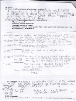


© Copyright 2026