
Roundell Evaporators
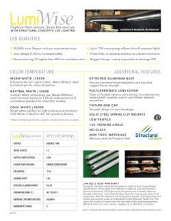
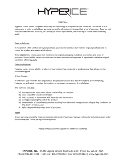
Roundell
Evaporators
PRODUCT DATA &
INSTALLATION
High Temperature Applications
(35 °F and Higher)
K30-R-PDI-16
Air Defrost
1064042
?
Questions about this product?
Email: [email protected]
Call: 1-844-893-3222 x520
?
Electrical Power: 115/1/60
• Compatable with Low GWP Refrigerants
• Direct backwall location and minimum height provides
maximum usable storage space.
• Textured heavy gauge aluminum cabinet - lightweight,
doesn’t show scratches.
• Rigid, slotted channel hangers simplify installation.
• Hinged drain pan for ease of cleaning and service.
• Full collar aluminum plate fins on expanded seamless
copper tubes ensure optimum heat transfer efficiency.
• Fan motors are inherently protected
• Optional PSC motors or EC motors (115V only)
INCLUDES RATINGS FOR
NOMENCLATURE
R
KEEPRITE
HALF ROUND EVAPORATOR
BTUH CAPACITY @
1 °F TD (60Hz)
e.g. 450 = 4500 @ 10 °F TD
ELECTRICAL DESIGNATION
A = 115/1/60
W = 208-230/1/60
375
A
CONTENTS PAGE
Nomenclature.......................................... Cover
Capacity Data...........................................
2
Electrical Data..........................................
2
Typical Field Wiring.................................
2
Dimensional & Physical Data.................
3
Thermostatic Expansion Valve..............
4
Installation Instructions..........................
5
Service Parts ..........................................
6
Service Log..............................................
6
Warranty...................................................
7
Project Information.................................
7
“As Built” Service Parts......................... Back
04/06/15
R
60Hz
CAPACITY DATA - ALL MODELS
Model
R375
R485
R595
R775
R905
R1025
R1305
R2050
Number of Fans
1
3540
(1038)
3360
(984)
3730
(1093)
3540
(1038)
3357
(984)
770
(363)
1
4640
(1359)
4392
(1287)
4880
(1430)
4640
(1359)
4392
(1287)
770
(363)
1
5750
(1684)
5445
(1596)
6050
(1773)
5750
(1684)
5445
(1596)
1280
(604)
1
7510
(2199)
7110
(2084)
7900
(2315)
7510
(2199)
7110
(2084)
1300
(614)
1
8460
(2478)
8010
(2347)
8900
(2608)
8500
(2478)
8010
(2347)
1380
(614)
1
9700
(2840)
9180
(2690)
10200
(2989)
9700
(2840)
9180
(2690)
2025
(956)
1
12200
(3563)
11600
(3376)
12800
(3751)
12200
(3563)
11520
(3376)
2000
(944)
2
19400
(5680)
18400
(5381)
20400
(5979)
19400
(5680)
18360
(5381)
4050
(1911)
1.4
(0.6)
1.9
(0.9)
2.3
(1.0)
3.3
(1.5)
3.6
(1.6)
4.1
(1.9)
5.3
(2.4)
8.3
(3.7)
R407A
R407C
Evap
Temp.
25°F
(-4°C)
Capacity
BTUH
(WATTS)
R404A
R507
R22
R134a
Air Flow
CFM (L/s)
Refrigerant **
Charge R407A
Lbs
(Kg)
Capacities rated using 10°F (5.6°C) TD & 100°F (38°C) liquid temperature.
Capacities at other TD within a range of 8 to 15 °F (4.4 to 8.3°C) are directly proportional to TD, or use formula: Capacity = Rated capacity ÷ 10 x TD.
For capacities at TD outside of range 8 to 15 °F (4.4 to 8.3°C), or liquid temperature lower than 75°F (24°), consult factory.
Capacities for R407A and R407C are based on mean temperature. Mean temperature is the average temperature between the saturated suction
temperature and the temperature feeding the evaporator. For dew point ratings, consult factory.
** REFRIGERANT CHARGE CONVERSION FACTORS
R407C
R404A
R507
R22
R134a
0.99
0.92
0.93
1.02
1.03
ELECTRICAL DATA
SHADED POLE MOTORS
MODEL QTY.
OPTIONAL P.S.C. MOTORS
POWER
TOTAL
H.P. RPM WATTS
MCA
SUPPLY
F.L.A.
MOP
MODEL QTY.
POWER
SUPPLY
H.P. RPM WATTS
TOTAL
MCA MOP
F.L.A.
R375
1
115/1/60 1/20 1550
120
1.6
2
15
R775
1
115/1/60
1/15 1060
128
1.32
1.65
15
R485
1
115/1/60 1/20 1550
120
1.6
2
15
R905
1
115/1/60
1/15 1060
128
1.32
1.65
15
R595
1
115/1/60 1/20 1550
120
1.6
2
15
R1025
1
115/1/60
1/15 1060
128
1.32
1.65
15
R775
1
115/1/60 1/15 1050
155
2.1
2.63
15
R1305
1
115/1/60
1/15 1060
128
1.32
1.65
15
R905
1
115/1/60 1/15 1050
155
2.1
2.63
15
R2050
2
115/1/60
1/15 1060
256
2.64
2.97
15
R1025
1
115/1/60 1/15 1050
155
2.1
2.63
15
R375
1
208-230/1/60 1/20 1600
90
0.29
0.36
15
R1305
1
115/1/60 1/15 1050
155
2.1
2.63
15
R485
1
208-230/1/60 1/20 1600
90
0.29
0.36
15
R2050
2
115/1/60 1/15 1050
310
4.2
4.73
15
R595
1
208-230/1/60 1/20 1600
90
0.29
0.36
15
R775
1
208-230/1/60 1/15 1060
84
0.54
0.68
15
OPTIONAL EC MOTORS
MODEL QTY.
R375
1
POWER
TOTAL
H.P. RPM WATTS
MCA
SUPPLY
F.L.A.
115/1/60 1/20 1550
26
0.5
0.63
R905
1
208-230/1/60 1/15 1060
84
0.54
0.68
15
MOP
R1025
1
208-230/1/60 1/15 1060
84
0.54
0.68
15
15
R1305
1
208-230/1/60 1/15 1060
84
0.54
0.68
15
R2050
2
208-230/1/60 1/15 1060
240
1.08
1.22
15
R485
1
115/1/60 1/20 1550
26
0.5
0.63
15
R595
1
115/1/60 1/20 1550
26
0.5
0.63
15
R775
1
115/1/60 1/12 1070
84
1.5
1.88
15
R905
1
115/1/60 1/12 1070
84
1.5
1.88
15
R1025
1
115/1/60 1/12 1070
84
1.5
1.88
15
R1305
1
115/1/60 1/12 1070
84
1.5
1.88
15
R2050
2
115/1/60 1/12 1070
168
3.0
3.38
15
K30-R-PDI-16
MCA = Minimum Circuit Ampacity
MOP = Maximum Overcurrent Protection
-2-
04/06/15
R
60Hz
TYPICAL FIELD WIRING
2nd FAN MOTOR
ON T2050 MODEL
DIMENSIONAL AND PHYSICAL DATA
MODELS R375 to T1305 (Single Fan)
MODEL R2050 (Double Fan)
AIR
FLOW
SUCTION
1” (25mm)
AIR
FLOW
EXTERNAL EQUALIZER
CONNECTION
EXTERNAL EQUALIZER CONNECTION
1/4” (5mm) O.D. (INSIDE CASING)
3 3/4”
(96mm)
1/4” (5MM) O.D. (INSIDE CASING)
1” (25mm)
SUCTION
3 3/4” A
(96mm)
D
5/8” (16mm) O.D. DRAIN
WITH PLASTIC SLEEVE
5/8” (16mm) O.D. DRAIN
WITH PLASTIC SLEEVE
AIR
FLOW
7/16” (11mm) DIA. HOLE
24 7/8”
(632mm)
AIR
FLOW
(APPROX.
15 FEET
THROW)
25 3/4
(654mm)
7/16” (11mm) DIA. HOLE
E
E
C
C
G
B
B
4” (102mm)
MAX
F
MODEL
R375
R485
R595
R775
R905
R1025
R1305
R2050
in
mm
in
mm
in
mm
in
mm
in
mm
4” (102mm) MAX.
F
A
B
C
D
E
F
G
8 1/8
(206.4)
11 1/8
(282.6)
11 1/8
(282.6)
12 5/8
(320.7)
12 5/8
(320.7)
33 1/4
(844.6)
39 1/4
(997.0)
42 1/4
(1073.1)
42 1/4
(1073.1)
74
(1879.6)
20 3/4
(527.0)
23 3/4
(603.3)
25 1/4
(641.4)
25 1/4
(641.4)
25 1/4
(641.4)
2
(50.8)
2 1/4
(57.2)
2 1/2
(63.5)
2 1/2
(63.5)
2 1/2
(63.5)
16 3/4
(425.5)
19 3/8
(492.1)
20 3/8
(417.5)
20 3/8
(417.5)
20 3/8
(417.5)
34 3/4
(882.7)
40 3/4
(1035.0)
43 3/4
(1111.3)
43 3/4
(1111.3)
75 1/2
(1917.5)
4 3/4
(120.7)
5 1/8
(130.2)
5 5/8
(142.9)
5 5/8
(142.9)
5 5/8
(142.9)
Suct. Conn. O.D.
in
mm
5/8
15.9
5/8
15.9
5/8
15.9
7/8
22.2
Shipping Weight
Lbs.
Kg.
72
32.7
76
34.5
98
44.5
104
47.2
7/8
22.2
108
49
7/8
7/8
22.2
22.2
114
124
51.2
56.2
1 1/8
28.6
187
84.8
NOTE: 5/8” (15.9 mm) O.D. Drain connection on all models.
1/2” (12.7 mm) Sweat TX Valve connection on all models.
K30-R-PDI-16
-3-
04/06/15
R
THERMOSTATIC EXPANSION VALVE
SELECTION CHART
60Hz
FOR +35°F ROOMS AND UP
AIR
DEFROST
MODEL
R375
R485
R595
R775
R905
R1025
R1305
R2050
SPORLAN VALVE MODEL
TD
°F
R407A R407C R22
R404A R507
R134a
10
SBFVE-AAA-C
SBFSE-AA-C
SBFJE-AA-C
12
SBFVE-AAA-C
SBFSE-AA-C
SBFJE-AA-C
15
SBFVE-AA-C
SBFSE-AA-C
SBFJE-AA-C
10
SBFVE-AA-C
SBFSE-AA-C
SBFJE-AA-C
12
SBFVE-AA-C
SBFSE-AA-C
SBFJE-AA-C
15
SBFVE-AA-C
SBFSE-A-C
SBFJE-A-C
10
SBFVE-AA-C
SBFSE-AA-C
SBFJE-AA-C
12
SBFVE-AA-C
SBFSE-A-C
SBFJE-A-C
15
SBFVE-AA-C
SBFSE-A-C
SBFJE-A-C
10
SBFVE-AA-C
SBFSE-A-C
SBFJE-A-C
12
SBFVE-AA-C
SBFSE-A-C
SBFJE-A-C
15
SBFVE-A-C
SBFSE-A-C
SBFJE-A-C
10
SBFVE-AA-C
SBFSE-A-C
SBFJE-A-C
12
SBFVE-A-C
SBFSE-A-C
SBFJE-A-C
15
SBFVE-A-C
SBFSE-A-C
SBFJE-A-C
10
SBFVE-AA-C
SBFSE-A-C
SBFJE-A-C
12
SBFVE-A-C
SBFSE-A-C
SBFJE-A-C
15
SBFVE-A-C
SBFSE-B-C
SBFJE-B-C
10
SBFVE-A-C
SBFSE-A-C
SBFJE-A-C
12
SBFVE-A-C
SBFSE-B-C
SBFJE-B-C
15
SBFVE-A-C
SBFSE-B-C
SBFJE-B-C
10
SBFVE-A-C
SBFSE-B-C
SBFJE-B-C
12
SBFVE-B-C
SBFSE-B-C
SBFJE-B-C
15
SBFVE-B-C
SBFSE-C-C
SBFJE-C-C
Selections based on 100° Liquid
K30-R-PDI-16
-4-
04/06/15
R
INSTALLATION INSTRUCTIONS
60Hz
APPLICATION
MOUNTING
High Temp Evaporators are designed for use with a wide
variety of popular refrigerants. At room temperatures above
34°F and evaporating temps no lower than 27°F the air flowing
through the coil will accomplish the defrost. Temperatures of
34°F and below (to -40°F) require positive defrosting. (either
Electric or Hot Gas). The coil must not be exposed to any
abnormal atmospheric or acidic environments. This may result
in corrosion to the cabinet and possible coil failure (leaks).
(Consult manufacturer for optional baked on phenolic protective coatings).
Mounting brackets with 7/16” dia holes are provided for flush
mounting to the ceiling. For details refer to dimensional data on
page 3.
Ensure that the ceiling is level since the drain pan has
been sloped for drainage during the defrost cycle.
DRAIN LINE
The drain line should be run from the drain connection, sloping
at least 4” per foot. A trap outside the room will prevent warm
air from entering through the tubing.
Connection should be made to proper drainage facilities that
comply with local regulations.
INSTALLATION
The installation and start-up of evaporators should only be
performed by qualified refrigeration mechanics.
This equipment should be installed in accordance with all applicable codes, ordinances and local by-laws.
Ensure that the drain pan has sufficient slope for proper
drainage (prevention of ice build up/blockage in pan).
PIPING
Inspect all equipment before unpacking for visible signs of
damage or loss. Check shipping list against material received
to ensure shipment is complete.
Refrigerant line sizes are important and may not be the same
size as the coil connections. (depends on the length of run) If
in doubt, consult “Recommended refrigerant line sizes” charts.
(Engineering Manuals or other recognized sources of
information).
IMPORTANT: Remember, you, the consignee, must make any
claim necessary against the transportation company.
Shipping damage or missing parts, when discovered at the
outset, will prevent later unnecessary and costly delays.
If damage or loss during transport is evident, make claim
to carrier, as this will be their responsibility, not the
manufacturer’s.
Wire system in accordance with governing standards and local
codes. See data and wiring diagram on page 2, for wiring arrangement. Electrical wiring is to be sized in accordance with
minimum ampacity rating.
INSPECTION
WIRING
SYSTEM CHECK
Before Start-Up:
1. All wiring should be in accordance with local codes.
2. Refrigerant lines should be properly sized.
3. Off-cycle defrost systems should include a liquid line
solenoid valve.
4. Thorough evacuation and, dehydration has been
performed.
5. The suction, discharge, and receiver service valves must
be open.
6. The system should include a liquid line drier moisture
indicator and suction filter.
7. Pour enough water into the drain pan to allow a good check
on drainage and seal the trap.
Should carton be damaged, but damage to equipment is not
obvious, a claim should be filed for “concealed damage” with
the carrier.
IMPORTANT: The electrical characteristics of the unit should
be checked at this time to make sure they correspond to those
ordered and to electrical power available at the job site.
Save all shipping papers, tags and instruction sheets for reference by installer and owner.
LOCATION
The unit location in the room should be selected to ensure
uniform air distribution throughout the entire space to be refrigerated. Make sure that the air is not blown directly out through
the opened door and that the product does not obstruct the
free circulation of air.
After Start-Up:
1. Check the compressor oil level to ensure the correct oil
charge.
2. Be sure that the expansion valve is properly set to provide
the correct amount of superheat.
3. Heavy moisture loads are usually encountered when
starting the system for the first time.
4. Check for proper evaporator fan blade rotation.
NOTE: These units drawn air through the fan and discharge air from the coil side.
When installing the unit adjacent to a wall sufficient
clearance (2” (50mm) minimum) must be provided to allow the
hinged drain pan to be lowered for servicing the unit. Channel
type hangers are provided. Rear hangers are slotted to facilitate installation. See dimensional data.
K30-R-PDI-16
MAINTENANCE
The unit should be periodically inspected for any dirt or
build-up on the fin surface and cleaned if necessary with a soft
whisk or brush.
-5-
04/06/15
SERVICE PARTS
FOR SERVICE PARTS LOOK-UP:
visit: http://www.k-rp.com/serv_parts.htm
email: [email protected]
call: 1-844-893-3222 x501
SERVICE LOG
DATE
K30-R-PDI-16
COM M ENTS
-6-
04/06/15
FINISHED GOODS WARRANTY
The terms and conditions as described below in the General Warranty Policy cover all products
manufactured by National Refrigeration.
GENERAL WARRANTY POLICY
Subject to the terms and conditions hereof, the Company warrants all Products, including Service
Parts, manufactured by the Company to be free of defects in material or workmanship, under normal use and application for a period of one (1) year from the original date of installation, or eighteen
(18) months from the date of shipment from the Company, whichever occurs first. Any replacement
part(s) so supplied will be warranted for the balance of the product’s original warranty. The part(s) to
be replaced must be made available in exchange for the replacement part(s) and reasonable proof
of the original installation date of the product must be presented in order to establish the effective
date of the warranty, failing which, the effective date will be based upon the date of manufacture plus
thirty (30) days. Any labour, material, refrigerant, transportation, freight or other charges incurred in
connection with the performance of this warranty will be the responsibility of the owner at the current rates and prices then in effect. This warranty may be transferred to a subsequent owner of the
product.
THIS WARRANTY DOES NOT COVER
(a) Damages caused by accident, abuse, negligence, misuse, riot, fire, flood, or Acts of God (b) damages
caused by operating the product in a corrosive atmosphere (c) damages caused by any unauthorized
alteration or repair of the system affecting the product’s reliability or performance (d) damages caused
by improper matching or application of the product or the product’s components (e) damages caused by
failing to provide routine and proper maintenance or service to the product (f) expenses incurred for the
erecting, disconnecting, or dismantling the product (g) parts used in connection with normal maintenance,
such as filters or belts (h) products no longer at the site of the original installation (i) products installed
or operated other than in accordance with the printed instructions, with the local installation or building
codes and with good trade practices (j) products lost or stolen.
No one is authorized to change this WARRANTY or to create for or on behalf of the Company any
other obligation or liability in connection with the Product(s). There is no other representation, warranty
or condition in any respect, expressed or implied, made by or binding upon the Company other than
the above or as provided by provincial or state law and which cannot be limited or excluded by such
law, nor will we be liable in any way for incidental, consequential, or special damages however caused.
The provisions of this additional written warranty are in addition to and not a modification of or subtraction
from the statutory warranties and other rights and remedies provided by Federal, Provincial or State laws.
PROJECT INFORMATION
System
Model Number
Date of Start-Up
Serial Number
Service Contractor
Refrigerant
Phone
Electrical Supply
Fax
K30-R-PDI-16
-7-
04/06/15
“AS BUILT” SERVICE PARTS LIST
Service Parts List
Label
To Be Attached
HERE
NATIONAL REFRIGERATION &
AIR CONDITIONING CANADA CORP.
1-800-463-9517 (519) 751-0444 www.k-rp.com [email protected] fax: (519) 753-1140
CANADA: 159 ROY BLVD., BRANTFORD, ON, N3R 7K1
USA: 985 WHEELER WAY, LANGHORNE, PA 19047
Due to National Refrigeration’s policy of continuous product improvement, we reserve the right to make changes without notice.
04/06/15


© Copyright 2026