
• W A R... • H A N...
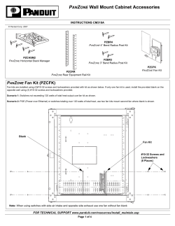
•
AGRICULTURAL
&
INDUSTRIAL
CEILING FANS
• I N S TA L L AT I O N I N S T R U C T I O N S •
WARNING
•
1. Be sure to shut off electrical supply at circuit breaker before
installation. This installation is to be in accordance with local and
national electrical codes.
2. To reduce the risk of personal injury, DO NOT bend the blade
brackets when installing or cleaning the fan. Also, DO NOT insert
foreign objects in between rotating blades.
3. Any field alteration or changed downrods “WARRANTY VOIDS” any
hanging mechanism warranty or liability.
•
CAUTION
•
1. Installation work and electrical wiring must be done in accordance
with NEC (NFPA 70) and all applicable local codes and standards
including fire rated constructions and must be done by a
qualified electrician.
2. Remove fan from the carton carefully and check for shipping
damage. Check blades for bends and dents. In case assistance
is required please contact our service centre.
READ AND SAVE THESE INSTRUCTIONS
Note to Installer: You are obligated to pass these instructions on to
building maintenance or location Supervisor.
•
1. Using Machine Threaded Hooks for Steel Frame Ceiling (Fig. 1)
- Put the threaded J-Hook through junction box, winding nut to
bottom of thread.
- Insert the hook with the box through slit in bottom of open web
steel joists.
- Put large washer, lock washer and nut on the hook loosely.
- Secure spark plate onto junction box. Feed power wires through
spark plate for ease of wiring. (Spark plate is not needed for fan
with a cord and plug.)
- Hang the fan on the J-hook.
- Tighten the top lock washer and nut until secure.
- Install the Eye Bolt onto the steel frame ceiling beside the junction
box.
2. Insert the safety cable into the Eye Bolt through the slit and then
close the Eye Bolt loop. NOTE: Knot in safety cable is there for
extra strength. DO NOT UNDO KNOT.
3. Connect the lead wires to the power supply, (shown in Fig. 3).
FOR CORD & PLUG FANS:
Simply insert the plug into the receptacle at the ceiling.
FOR FORWARD/REVERSE MODELS:
4. Do not install the fan close to the door entrance. Ensure at least
3 feet distance from end of the blades.
Downdraft Direction:
Connect blue and black wires of fan to “hot” wire, red and white wires
to neutral wire and green wire to ground wire.
6. Fan blades must be at a minimum of 10 feet from the floor when
the fan is installed.
CP48HPWP, CP56HPWP,
CP60HPWP, CP36, CP48, CP56BR, CP56F&R,
CP56S, CP56C&P
HANGING & ASSEMBLY
3. Check that the supply voltage corresponds to the rated voltage
on motor of fan you have selected.
5. Ensure that you have a water proof model if installing in a
wet/damp location.
MODELS
•
7. Make sure hanger hook is mounted securely to the structural
ceiling.
8. Fan is suitable for operation on Solid State controls.
9. The fan shall not directly be supported by the outlet box.
10. All set screws must be checked and re-tightened where necessary
after installation. No lubricants should be used on screws or
hooks.
11. To reduce the risk of personal injury install the safety cable
(per Fig. 1).
12. DO NOT attach blades before hanging the fan.
Updraft Direction:
Connect red and black wires of fan to “hot” wire, blue and white wires
to neutral wire and green wire to ground wire.
NOTE: Wiring connections should be turned upward and
pushed carefully up into the outlet box.
4. Slide up the upper canopy and affix it with the set screws. Leave a
minimum of 1/8” between ceiling and canopy.
5. Mount the fan blades onto the motor head with screws and spring
washers (see Fig. 2 for details).
NOTE: If wiring for updraft only: blades can be reversed for
increased fan performance.
6. Tighten set screws on upper and lower canopies.
M0090 - 03/16/11
Page 1 of 3
Both Updraft & Downdraft
Using Canarm CNFRMC5 Control
RED
BLUE
BLACK
WHITE
GREEN
MOTOR
•
TROUBLESHOOTING
•
CNFRMC5
RED
BLUE
YELLOW
WHITE
CONTROL
CNFRMC5
Trouble:
BLACK
120 VOLTS SUPPLY
WHITE
MODELS: CP36, CP48, CP56S, CP56BR, CP56F/R
HIGH PERFORMANCE MODELS: CP48, 56, 60 HPWP
Suggestion:
1. Fan will not start.
- Check fuses and circuit breakers
- Check wiring connections to fan.
- Check wiring connections in lower canopy.
Caution: Turn power off for last two items.
Downdraft
Figure 1
MC SERIES
CONTROL
(if applicable)
Reference Numbers:
1.
2.
3.
4.
5.
6.
7.
8.
9.
10.
Upper Canopy
Set Screw
Blade Mounting Screw
Blade Bracket
Fan Blade
Vibration Absorber
Spark Plate (NA for Cord & Plug)
Lower Canopy
Blade Mounting Spring Washer
Motor Head
11.
12.
13.
14.
15.
16.
17.
18.
19.
20.
Steel Frame Ceiling
J-Hook Nut
Spring Washer
Washer
Threaded J-Hook
Safety Cable
Lead Wires (or Cord & Plug)
Downrod
Eye Bolt
Junction Box (Not provided)
BLACK
BLUE
RED
WHITE
GREEN
MOTOR
BLACK
2. Fan sounds noisy.
- Check to make sure all screws in
motor are snug.
- Check to make sure that all blade
bracket screws are tight.
- Some motors are sensitive to signals
from solid state variable controls. If this
type of control is used some electrical
noise from the motor is normal and will
not affect performance.
For quiet operation use Canarm’s
models CQ004 “Church Quiet” controls.
- Allow a 24 hour break in period to
eliminate most noises.
3. Fan wobbles.
- Check that all blades are screwed firmly
to motor.
- Check distance from tip of blades to
ceiling, gently bend up or down until all
distances are the same.
- Make sure upper canopy is 1/8” from
ceiling.
- Make sure that hanging hooks are
secured tightly to ceiling.
120 VOLTS SUPPLY
WHITE
MODELS: CP36, CP48, CP56S, CP56BR, CP56F/R
HIGH PERFORMANCE MODELS: CP48, 56, 60 HPWP
Updraft
MC SERIES
CONTROL
(if applicable)
MOTOR
BLACK
RED
BLUE
WHITE
GREEN
BLACK
120 VOLTS SUPPLY
WHITE
MODELS: CP36, CP48, CP56S, CP56BR, CP56F/R
HIGH PERFORMANCE MODELS: CP48, 56, 60 HPWP
Both Updraft & Downdraft
Using Canarm MC Series Control and DPDT Switch
(Supplied by others)
Note: On the Double Pole, Double Throw Switch,
Jumper Pin 1 to 4, 3 to 6
BLACK
POTENTIOMETER
MOTOR
BLACK
BLUE
RED
WHITE
GREEN
120 VOLTS SUPPLY
11
66
2
2
5
5
3
4
3
4
DPDT SWITCH
WHITE
MODELS: CP36, CP48, CP56S, CP56BR, CP56F/R
HIGH PERFORMANCE MODELS: CP48, 56, 60 HPWP
Figure 2
Figure 3
Page 2 of 3
•
OPTIONAL FAN GUARD
•
•
MAINTENANCE
•
•
5 YEAR WARRANTY
•
Models: CP36, CP48, CP56BR, CP56F&R, CP56S, CP56C&P
- When properly maintained, fans can be expected to give years of trouble
free operation.
- Properly maintained fans must be inspected every 3000 hours for
vibration and wear on the support mechanism and that all screws, nuts,
etc. are tight.
- Refer to (Fig. 4) for maintenance schedule.
NOTE: If vibration and/or wear is noticeable the fan should be
removed from service and repaired or replaced by a
qualified person.
B
These models are guaranteed to be free from defects in workmanship
and material for a period of five (5) years from date of purchase. Within
the first (1) year from date of purchase any defective product should be
returned to your RETAIL OUTLET along with proof of purchase. For the
balance of the warranty, the MOTOR WINDINGS ONLY, shall be free of
defects. We will correct such defects or replace the motor at our option
if the product is returned FREIGHT PREPAID to Canarm.
•
•
Models: CP48HPWP, CP56HPWP, CP60HPWP
DATE INSTALLED:
Visible Vibration
Check Every
4 Months
3 YEAR WARRANTY
Support Mechanism
Refer to Installation
Instructions
(Every 4 Months)
Screws
Refer to Installation
Instructions
(Every 4 Months)
These models are guaranteed to be free from defects in workmanship
and material for a period of three (3) years from date of purchase. Within
the first (1) year from date of purchase any defective product should be
returned to your RETAIL OUTLET along with proof of purchase. For the
balance of the warranty, the MOTOR WINDINGS and BEARINGS
ONLY, shall be free of defects. We will correct such defects or replace
the motor at our option if the product is returned FREIGHT PREPAID to
Canarm.
•
A
5 YEAR & 3 YEAR WARRANTY
•
All costs of removing and re-installing the product are YOUR
RESPONSIBILITY. Damage to any part such as by accident, misuse,
improper installation or by affixing any accessories IS NOT covered by
this warranty. As a result of varying climatic conditions in your area this
warranty does not cover any changes in finishes, including rusting,
pitting, corroding, tarnishing or peeling.
Guard
Size
CP93-56KD
WARRANTY VOID:
In cases of alteration, abuse, installation not in accordance with
instructions or REMOVAL of the C.S.A. Sticker.
Dimension
A
61”
B
NOTE: Canarm does not recommend the changing of downrods on
industrial ceiling fans. THIS WARRANTY IS VOID IF THE DOWNROD
HAS BEEN CHANGED. We offer 16” and 36” downrod models.
CP56S is 36”, and all other sizes are 16”.
26”
CANARM LTD.
2157 Parkedale Ave.,
Brockville, Ontario
K6V 5V6
PH: (613) 342-5424
FX: 1-800-263-4598
Note: In applications where fan may be damaged (i.e. Gymnasium,
or in applications where maintenance cannot or will not be
done), the above illustrated fan guard should be used.
Figure 4
CANARM LTEE.
2555 Rue Bernard
Lefebvre
Laval, Quebec
H7C 0A5
PH: (450) 665-2535
FX: (450) 665-0910
CANARM LTD.
808 Commerce Park Drive,
Ogdensburg, NY
13669
PH: 1-800-267-4427
FX: 1-800-263-4598
Page 3 of 3


© Copyright 2026