
52317 VM-405PBBD2 MM.book
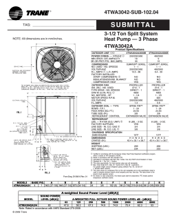
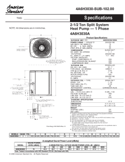
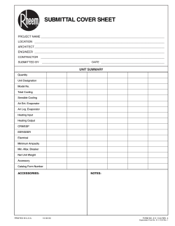
VM-405 PBBD2
TK 52317-E-1-MM (Rev. 1, 2/09)
Copyright© 2004 Thermo King Corp., Minneapolis, MN, U.S.A.
Printed in U.S.A.
The contents of this manual covers information related to the VM-405 PBBD2 unit.
For further information, refer to…
VM-405 PBBD2 Operating Manual
TK 52318-E-1-OP
The information in this manual is provided to assist owners, operators and service people in the proper upkeep
and maintenance of Thermo King units.
This manual is published for informational purposes only and the information so provided should not be considered
as all-inclusive or covering all contingencies. If further information is required, Thermo King Corporation should be
consulted.
Sale of product shown in this manual is subject to Thermo King’s terms and conditions including, but not limited to,
the Thermo King Limited Express Warranty. Such terms and conditions are available upon request.
Thermo King’s warranty will not apply to any equipment which has been “so repaired or altered outside the manufacturer’s plants as, in the manufacturer’s judgment, to effect its stability.”
No warranties, express or implied, including warranties of fitness for a particular purpose or merchantability, or warranties arising from course of dealing or usage of trade, are made regarding the information, recommendations, and descriptions contained herein. Manufacturer is not responsible and will not be held
liable in contract or in tort (including negligence) for any special, indirect or consequential damages,
including injury or damage caused to vehicles, contents or persons, by reason of the installation of any
Thermo King product or its mechanical failure.
Recover Refrigerant
At Thermo King, we recognize the need to preserve the environment and limit the potential harm to the ozone layer that can
result from allowing refrigerant to escape into the atmosphere.
We strictly adhere to a policy that promotes the recovery and
limits the loss of refrigerant into the atmosphere.
In addition, service personnel must be aware of Federal regulations concerning the use of refrigerants and the certification of
technicians. For additional information on regulations and technician certification programs, contact your local THERMO KING
dealer.
R-404A
WARNING: Use ONLY Polyol Ester based refrigeration compressor oil (TK P/N 203-513).
DO NOT use Polyol Ester based oil in standard Thermo King units.
DO NOT mix Polyol Ester and standard synthetic compressor oils.
Keep Polyol Ester compressor oil in tightly sealed containers. If Polyol Ester oil becomes
contaminated with moisture or standard oils, dispose of properly—DO NOT USE!
WARNING: When servicing Thermo King R-404A units, use only those service tools
certified for and dedicated to R-404A refrigerant and Polyol Ester compressor oils.
Residual non-HFC refrigerants or oils will contaminate R-404A systems.
Table of Contents
Safety Precautions . . . . . . . . . . . . . . . . . . . . . . . . . . . . . . . . . . . . . . . . . . . . . . . . . . . . . . . . . . . . . . . . . . . . . . . . . i
Specifications . . . . . . . . . . . . . . . . . . . . . . . . . . . . . . . . . . . . . . . . . . . . . . . . . . . . . . . . . . . . . . . . . . . . . . . . . . . . .1
Maintenance Inspection Schedule . . . . . . . . . . . . . . . . . . . . . . . . . . . . . . . . . . . . . . . . . . . . . . . . . . . . . . . . . . . . .3
Unit Description . . . . . . . . . . . . . . . . . . . . . . . . . . . . . . . . . . . . . . . . . . . . . . . . . . . . . . . . . . . . . . . . . . . . . . . . . . . .5
Defrost Timer. . . . . . . . . . . . . . . . . . . . . . . . . . . . . . . . . . . . . . . . . . . . . . . . . . . . . . . . . . . . . . . . . . . . . . . . . . . . .5
Protection Features . . . . . . . . . . . . . . . . . . . . . . . . . . . . . . . . . . . . . . . . . . . . . . . . . . . . . . . . . . . . . . . . . . . . . . . .5
Operation. . . . . . . . . . . . . . . . . . . . . . . . . . . . . . . . . . . . . . . . . . . . . . . . . . . . . . . . . . . . . . . . . . . . . . . . . . . . . . . .5
Operating Instructions . . . . . . . . . . . . . . . . . . . . . . . . . . . . . . . . . . . . . . . . . . . . . . . . . . . . . . . . . . . . . . . . . . . . . .7
Starting the Unit. . . . . . . . . . . . . . . . . . . . . . . . . . . . . . . . . . . . . . . . . . . . . . . . . . . . . . . . . . . . . . . . . . . . . . . . . . .7
Electronic Controls . . . . . . . . . . . . . . . . . . . . . . . . . . . . . . . . . . . . . . . . . . . . . . . . . . . . . . . . . . . . . . . . . . . . . . . .8
Electrical Maintenance . . . . . . . . . . . . . . . . . . . . . . . . . . . . . . . . . . . . . . . . . . . . . . . . . . . . . . . . . . . . . . . . . . . . .13
Electric Box . . . . . . . . . . . . . . . . . . . . . . . . . . . . . . . . . . . . . . . . . . . . . . . . . . . . . . . . . . . . . . . . . . . . . . . . . . . . .13
P.C. Board. . . . . . . . . . . . . . . . . . . . . . . . . . . . . . . . . . . . . . . . . . . . . . . . . . . . . . . . . . . . . . . . . . . . . . . . . . . . . .14
Connectors . . . . . . . . . . . . . . . . . . . . . . . . . . . . . . . . . . . . . . . . . . . . . . . . . . . . . . . . . . . . . . . . . . . . . . . . . . . . .14
Fuses. . . . . . . . . . . . . . . . . . . . . . . . . . . . . . . . . . . . . . . . . . . . . . . . . . . . . . . . . . . . . . . . . . . . . . . . . . . . . . . . . .14
Relays . . . . . . . . . . . . . . . . . . . . . . . . . . . . . . . . . . . . . . . . . . . . . . . . . . . . . . . . . . . . . . . . . . . . . . . . . . . . . . . . .15
Troubleshooting Cab Control Box M13 . . . . . . . . . . . . . . . . . . . . . . . . . . . . . . . . . . . . . . . . . . . . . . . . . . . . . . . .16
Defrost Maintenance . . . . . . . . . . . . . . . . . . . . . . . . . . . . . . . . . . . . . . . . . . . . . . . . . . . . . . . . . . . . . . . . . . . . . . .19
Defrost Description . . . . . . . . . . . . . . . . . . . . . . . . . . . . . . . . . . . . . . . . . . . . . . . . . . . . . . . . . . . . . . . . . . . . . . 19
Defrost Components . . . . . . . . . . . . . . . . . . . . . . . . . . . . . . . . . . . . . . . . . . . . . . . . . . . . . . . . . . . . . . . . . . . . . .19
Testing the Defrost System . . . . . . . . . . . . . . . . . . . . . . . . . . . . . . . . . . . . . . . . . . . . . . . . . . . . . . . . . . . . . . . . .20
Refrigeration Maintenance . . . . . . . . . . . . . . . . . . . . . . . . . . . . . . . . . . . . . . . . . . . . . . . . . . . . . . . . . . . . . . . . . .21
Charging an Evacuated Unit by Weight . . . . . . . . . . . . . . . . . . . . . . . . . . . . . . . . . . . . . . . . . . . . . . . . . . . . . . .21
High Pressure Cutout Switch . . . . . . . . . . . . . . . . . . . . . . . . . . . . . . . . . . . . . . . . . . . . . . . . . . . . . . . . . . . . . . .22
Refrigeration Service Operations. . . . . . . . . . . . . . . . . . . . . . . . . . . . . . . . . . . . . . . . . . . . . . . . . . . . . . . . . . . . .23
Compressor. . . . . . . . . . . . . . . . . . . . . . . . . . . . . . . . . . . . . . . . . . . . . . . . . . . . . . . . . . . . . . . . . . . . . . . . . . . . .23
Condenser Coil . . . . . . . . . . . . . . . . . . . . . . . . . . . . . . . . . . . . . . . . . . . . . . . . . . . . . . . . . . . . . . . . . . . . . . . . . .23
Filter Drier . . . . . . . . . . . . . . . . . . . . . . . . . . . . . . . . . . . . . . . . . . . . . . . . . . . . . . . . . . . . . . . . . . . . . . . . . . . . . .23
Evaporator Assy . . . . . . . . . . . . . . . . . . . . . . . . . . . . . . . . . . . . . . . . . . . . . . . . . . . . . . . . . . . . . . . . . . . . . . . . .24
High Pressure Cutout (HPCS). . . . . . . . . . . . . . . . . . . . . . . . . . . . . . . . . . . . . . . . . . . . . . . . . . . . . . . . . . . . . . .24
Low Pressure Cutout Switch . . . . . . . . . . . . . . . . . . . . . . . . . . . . . . . . . . . . . . . . . . . . . . . . . . . . . . . . . . . . . . . .24
Hot Gas Solenoid Valve . . . . . . . . . . . . . . . . . . . . . . . . . . . . . . . . . . . . . . . . . . . . . . . . . . . . . . . . . . . . . . . . . . .25
Low Side Pumpdown Procedure . . . . . . . . . . . . . . . . . . . . . . . . . . . . . . . . . . . . . . . . . . . . . . . . . . . . . . . . . . . . .25
Compressor Pumpdown Procedures . . . . . . . . . . . . . . . . . . . . . . . . . . . . . . . . . . . . . . . . . . . . . . . . . . . . . . . . .25
Installing and Purging a Gauge Manifold Equipped with Low Loss Fittings . . . . . . . . . . . . . . . . . . . . . . . . . . . .26
Removing the Gauge Manifold . . . . . . . . . . . . . . . . . . . . . . . . . . . . . . . . . . . . . . . . . . . . . . . . . . . . . . . . . . . . . .26
Setting The CPR Valve . . . . . . . . . . . . . . . . . . . . . . . . . . . . . . . . . . . . . . . . . . . . . . . . . . . . . . . . . . . . . . . . . . .26
Table of Contents (continued)
Structural Maintenance . . . . . . . . . . . . . . . . . . . . . . . . . . . . . . . . . . . . . . . . . . . . . . . . . . . . . . . . . . . . . . . . . . . . 29
Unit Inspection . . . . . . . . . . . . . . . . . . . . . . . . . . . . . . . . . . . . . . . . . . . . . . . . . . . . . . . . . . . . . . . . . . . . . . . . . 29
Evaporator Coil . . . . . . . . . . . . . . . . . . . . . . . . . . . . . . . . . . . . . . . . . . . . . . . . . . . . . . . . . . . . . . . . . . . . . . . . . 29
Condenser Coil . . . . . . . . . . . . . . . . . . . . . . . . . . . . . . . . . . . . . . . . . . . . . . . . . . . . . . . . . . . . . . . . . . . . . . . . . 29
Unit Mounting Bolts . . . . . . . . . . . . . . . . . . . . . . . . . . . . . . . . . . . . . . . . . . . . . . . . . . . . . . . . . . . . . . . . . . . . . . 29
Mechanical Diagnosis . . . . . . . . . . . . . . . . . . . . . . . . . . . . . . . . . . . . . . . . . . . . . . . . . . . . . . . . . . . . . . . . . . . . . 31
Electrical Mechanical Diagnosis . . . . . . . . . . . . . . . . . . . . . . . . . . . . . . . . . . . . . . . . . . . . . . . . . . . . . . . . . . . . 33
Refrigeration Diagnosis . . . . . . . . . . . . . . . . . . . . . . . . . . . . . . . . . . . . . . . . . . . . . . . . . . . . . . . . . . . . . . . . . . . 37
Wiring Diagrams and Schematic Index . . . . . . . . . . . . . . . . . . . . . . . . . . . . . . . . . . . . . . . . . . . . . . . . . . . . . . . 39
Safety Precautions
GENERAL PRACTICES
REFRIGERANT
1.
ALWAYS WEAR GOGGLES OR SAFETY
GLASSES. Refrigerant liquid, refrigeration oil, and
battery acid can permanently damage the eyes (see First
Aid under Refrigeration Oil).
2.
Never operate the unit with the compressor discharge
valve closed.
Although fluorocarbon refrigerants are classified as safe
refrigerants, certain precautions must be observed when
handling them or servicing a unit in which they are used.
When exposed to the atmosphere from the liquid state, fluorocarbon refrigerants evaporator rapidly, freezing anything
they contact.
3.
Keep your hands, clothing and tools clear of the fans
and belts when the unit is running. This should also be
considered when opening and closing the compressor
service valves.
First Aid
4.
Make sure gauge manifold hoses are in good condition.
Never let them come in contact with a belt, fan motor
pulley, or any hot surface.
•
EYES: For contact with liquid, immediately flush eyes
with large amounts of water and get prompt medical
attention.
5.
Never apply heat to a sealed refrigeration system or
container.
•
6.
Fluorocarbon refrigerants, in the presence of an open
flame or electrical short, produce toxic gases that are
severe respiratory irritants capable of causing death.
SKIN: Flush area with large amounts of lukewarm
water. Do not apply heat. Remove contaminated clothing and shoes. Wrap burns with dry, sterile, bulky
dressing to protect from infection/injury. Get medical
attention. Wash contaminated clothing before reuse.
7.
Make sure all mounting bolts are tight and are of correct length for their particular application.
•
8.
Use extreme caution when drilling holes in the unit.
The holes may weaken structural components, and
holes drilled into electrical wiring can cause fire or
explosion.
INHALATION: Move victim to fresh air and use CPR
if necessary. Stay with victim until arrival of emergency medical personnel.
9.
In the event of frost bite, the objectives of First Aid are to
protect the frozen area from further injury, to warm the
affected area rapidly and to maintain respiration.
REFRIGERATION OIL
Avoid refrigeration oil contact with the eyes. Avoid prolonged or repeated contact of refrigeration oil with skin or
clothing. Wash thoroughly after handling refrigeration oil to
prevent irritation.
Use caution when working around exposed coil fins.
The fins can cause painful lacerations.
10. Use caution when working with a refrigerant or refrigeration system in any closed or confined area with a
limited air supply (for example, a truck box or garage).
Refrigerant tends to displace air and can cause oxygen
depletion resulting in suffocation and possible death.
First Aid
In case of eye contact, immediately flush with plenty of
water for at least 15 minutes. Wash skin with soap and
water. CALL A PHYSICIAN.
11. EPA Section 608 Certification is needed to work on
refrigeration systems.
i
Safety Precautions (Rev. 1, 2/09)
ELECTRICAL HAZARDS
First Aid
High Voltage
IMMEDIATE action must be initiated after a person has
received an electrical shock. Obtain immediate medical
assistance if available.
When servicing or repairing a refrigeration unit, the possibility of serious or even fatal injury from electrical shock
exists. Extreme care must be used when working with an
operating refrigeration unit. Lethal voltage potentials can
exist on connections in the high voltage tray of the control
box.
The source of shock must be immediately removed by
either shutting down the power or removing the victim from
the source. If it is not possible to shut off the power, the wire
should be cut with either an insulated instrument (e.g., a
wooden handled axe or cable cutters with heavy insulated
handles) or by a rescuer wearing electrically insulated
gloves and safety glasses. Whichever method is used do not
look at the wire while it is being cut. The ensuing flash can
cause burns and blindness.
Precautions
1.
When working on high voltage circuits on the refrigeration unit, do not make any rapid moves. If a tool drops,
do not grab for it. People do not contact high voltage
wires on purpose. It occurs from an unplanned movement.
2.
Use tools with insulated handles that are in good condition. Never hold metal tools in your hand if exposed,
energized conductors are within reach.
3.
Treat all wires and connections as high voltage until a
meter and wiring diagram show otherwise.
4.
Never work alone on high voltage circuits on the refrigeration unit, another person should always be standing
by in the event of an accident to shut off the refrigeration unit and to aid a victim.
5.
Have electrically insulated gloves, cable cutters and
safety glasses available in the immediate vicinity in the
event of an accident.
If the victim has to be removed from a live circuit, pull the
victim off with a non-conductive material. Use the victim’s
coat, a rope, wood, or loop your belt around the victim’s leg
or arm and pull the victim off. DO NOT TOUCH the victim.
You can receive a shock from current flowing through the
victim’s body. After separating the victim from power
source, check immediately for the presence of a pulse and
respiration. If a pulse is not present, start CPR (Cardio Pulmonary Resuscitation) and call for emergency medical
assistance. If a pulse is present, respiration may be restored
by using mouth-to-mouth resuscitation, but call for emergency medical assistance.
Low Voltage
Control circuits used in the refrigeration unit are low voltage (24 volts dc). This voltage potential is not considered
dangerous, but the large amount of current available (over
30 amperes) can cause severe burns if shorted or ground.
Do not wear jewelry, watch or rings. These items can short
out electrical circuits and cause severe burns to the wearer.
ii
Specifications
Design Features
•
Manual Defrost Switch
•
M13 Controller
•
Receiver Tank with Outlet Service Valve
•
Digital Thermometer
•
2HP Semihermetic Compressor 50/60 Hz
•
Electronic Thermostat, adjustable
from -26 F to 86 F
•
Compressor Thermal Protection
•
Hourmeter
•
Defrost Timer
•
100W Lamp Plug
•
Hot Gas Defrost
•
Draining Heater Wire Resistances
•
Defrost Termination Switch
•
Electric Resistant Heaters (750 W)
Standby AC Motor
Voltage
230/400
Phase Frequency
3
50/60 Hz
Horsepower
Full Load
Current
2
14.1/8.1A
Refrigeration Specifications
Total System Oil Charge
1250 cc (42.2 oz.)
Compressor Oil Type
Polyol Ester P/N 203513
Refrigerant Charge and Type
2.2 kg (4.8 lb) R-404A
Defrost Method
Hot Gas
Defrost Termination Switch:
Opens
Closes
8.9 ± 3C (48 ± 5.4 F)
2.2 ± 3C (36 ± 5.4 F)
High Pressure Cutout Switch
Opens
Closes
450 ± 10 psi
375 ± 10 psi
Low Pressure Cutout Switch
Opens
Closes
5 to 11 inch. Vacuum
27.6 to 48.3 kPa (4 to 7 psi)
Defrost Timer:
Initiation Interval
From 1 minute to 10 hours
Termination Interval
When Defrost Termination Switch opens
CAUTION: When the oil is removed from the compressor, oil level should be noted so that the same
level can be maintained in the replacement compressor.
CAUTION: Polyol Ester compressor oil should be used in standard Thermo King units, and PAG-type
or mineral oils should not be added to systems using R404A.
1
Specifications (Rev. 1, 2/09)
Condenser & Evaporator Fan Motors
Voltage
Power Rating
in W.
Number
Full Load RPM
Full Load Current
Evaporator
26 V
2
100
2800
5.2 A
Condensor
26 V
1
180
2800
8.9 A
Fuses
Voltage
Evaporator
fan
Fuse 1
Evaporator
fan
Fuse 2
24 V
10 A
10 A
Voltage
External
lamp
Fuse 6
External
lamp
Fuse 7
24 V
1A
Condenser
fan
Fuse 3
M-13
Fuse 4
15 A
3A
M-13
Fuse 4/1
3A
1A
Hot Gas Solenoid Coils
Voltage
Current
Resistance
24 V
1.3 A
20 Ohms
Voltage AC
Number
Power in W.
Full Load Current
220 V
2
750
3.5 A
Heaters
2
Transformer
Fuse 5
5A
Maintenance Inspection Schedule
First Week Inspection and Maintenance
AFTER FIRST WEEK OF OPERATION:
• Tighten the unit and mount bracket mounting bolts
Bi-monthly
Annually
Inspect/Service These Items
ELECTRICAL
•
•
•
•
•
•
•
•
Check defrost initiation and termination.
Check thermostat cycle sequence.
Check operation of protection shutdown circuits.
Check thermostat and thermometer calibration in 32 F (0 C) ice-water bath.
Inspect wire harness for damaged wires or connections.
REFRIGERATION
•
•
•
Check refrigerant level.
Replace dehydrator.
STRUCTURAL
•
•
•
•
•
•
•
•
•
•
Visually inspect unit and refrigerant hoses for fluid leaks.
Visually inspect unit for damaged, loose or broken parts.
Clean defrost drains.
Clean entire unit including evaporator coil and condenser coil.
Check all unit mounting bolts, brackets, lines, etc.
3
4
Unit Description
PROTECTION FEATURES
The Thermo King VM 405 PBBD2 refrigeration system is a
one-piece nose mounted unit. It uses a semihermetic compressor in the condenser section for cooling operation.
•
High Pressure Cutout Switch
The High Pressure Cutout Switch is a pressure-sensitive switch located in the discharge line. If the discharge pressure rises above 450 psi (3100 kPa), the
switch opens the circuit to the PR Relay to stop the
unit. When the discharge pressure falls below 375 psi
(2600 kPa), the switch closes.
The unit is designed for low and medium temperature
small-sized compartments. It can cool and defrost on electric compressor operation to refrigerate one compartment
with R404A. Heating is accomplished by connecting the
heating resistances.
The control circuits operate on 24 Vdc rectified from an AC
transformer. Each refrigeration system is protected by high
and low pressure cutout switches.
•
Low Pressure Cutout Switch
The Low Pressure Cutout Switch is a pressure-sensitive
switch located in the suction line. If the pressure falls
below 5 to 11 inch vacuum, the switch opens the circuit
to the PR Relay to stop unit operation. The switch
closes at 4 to 7 psi.
Unit operation is performed from a remote control box. It
includes an On/Off switch, manual defrost switch, thermometer, thermostat, thermostat adjustment, and indicator
lights.
Compressor operation is controlled by the thermostat, energizing the compressor contact during cooling operation.
•
Overload Relay Protection for Electric Motor
•
Overload Relay Protection for heater resistance
Defrost: A hot gas solenoid valve provides local heat to the
evaporator by means of hot gas from the discharge line. An
electronic defrost timer can initiate defrost automatically.
Defrost is normally terminated by the defrost termination
switch mounted on the evaporator coil. The defrost cycle
can be terminated by pressing the On/Off switch.
•
Fuses
•
Power Cord LED
•
Overload Relay LED
•
Thermistor: Disconnects AC motor if its temperature
reaches a threshold value.
DEFROST TIMER
OPERATION
The defrost timer automatically initiates the defrost cycle at
preset intervals.
General
The Defrost Timer is powered directly by the standby power
supply. This means that the Defrost Timer is counting whenever the unit is connected to the main supply (while Klixon
is closed), even when the unit is switched off.
These units cycle among Heat, Cool and Null to maintain
the box temperature at the thermostat setpoint. The operating modes are: Cool, Null, Heat and Defrost.
The thermostat controls the operation of the unit by energizing and de-energizing the Power Relay PR.
When the Power Relay is energized, the condenser fans are
powered up (as well as the compressor motor).
5
Unit Description (Rev. 1, 2/09)
The Defrost cycle will continue until the evaporator coil
temperature rises to 48 F, causing the defrost termination
switch to open. Defrost cycle can also be terminated by
pressing the On/Off switch twice.
When the unit is connected to the main supply, the external
lamp is powered up by 110 V.
Operating Modes
Cool
1
The thermostat energizes the Power Relay at box temperatures higher than setpoint. The thermostat keeps the Power
Relay energized while the box temperature is higher than
4 F (2.2 C) above setpoint. The Power Relay energizes the
evaporator and condenser fan relays, the drain heaters and
the compressor contactor. The fans and the compressor run
and the unit cools.
4
6
5
2
3
Null
The thermostat shifts from Cool to Null at box temperatures
lower than setpoint. The thermostat shifts the unit from
Cool to Heat at 4 F (2.2 C) below the setpoint. The thermostat shifts the unit from Heat to Null at setpoint.
1.
2.
3.
4.
5.
6.
7.
8.
Heat
The thermostat shifts the unit to Heat at temperatures more
than 4 F (2.2 C) below the thermostat setpoint. The thermostat keeps the unit running in Heat until the temperature
reaches the thermostat setpoint.
7
8
Temperature Drop
Setpoint
4F
Temperature Rise
4F
Cool
Null
Heat
Operating Modes
When the unit is in Heat mode, the thermostat drives the
heater contactor, the evaporator fans and the electric resistant heaters, and the unit heats.
Defrost
The Defrost cycle can be initiated any time the evaporator
coil temperature is below 36 F. Defrost is initiated automatically by the defrost timer, or manually by pressing the manual defrost switch.
When the Power Relay is energized, the drain heaters are
activated and the defrost relay energizes the Solenoid Valve
PS to route hot refrigerant gas to the evaporator. The defrost
relay also interrupts power to the fan relays to stop the evaporator and condenser fans during defrost.
6
ANA144
Operating Instructions
Leaks
After Start Inspection
Inspect for refrigerant leaks and worn refrigerant lines.
Thermostat
Electrical
Dial the thermostat setting above and below the box
temperature to check thermostat operation.
Electrical connections should be securely fastened. Wires
and terminals should be free of corrosion, cracks or moisture.
Pre-Cooling
With the thermostat set at the desired temperature, allow the
unit to run for one-half to one hour before loading the container. Pre-cooling will remove residual body heat and
moisture from the box interior and provide a good test of the
refrigeration system.
Defrost Drain
Check the defrost drain hose and fittings to be sure that they
are open so condensation can run out during defrosting.
Check the bottom end of the drain hose to be sure that it is
not plugged or crushed.
Defrost
When the unit has finished pre-cooling, the container
interior (evaporator temperature dropped below 2.2 C/36 F),
initiate a defrost cycle with the manual defrost switch. The
defrost cycle should end automatically.
Structural
Visually check for physical damage.
Sightglass
Loading Procedure
Check for proper refrigerant charge level.
1.
Be sure the unit is OFF before opening the door to minimize frost accumulation on the evaporator coil and
heat gain inside the box.
2.
Spot check and record load temperature while loading.
Especially note any off-temperature product.
3.
Load product so that there is adequate space for air circulation completely around the load. DO NOT block
the evaporator inlet or outlet.
4.
Products should be pre-cooled before loading. Thermo
King units are designed to maintain loads at a consistent temperature, NOT to cool down hot loads.
STARTING THE UNIT
Electric Operation
1.
2.
3.
Connect the external power supply to the power receptacle. Make sure that the power supply voltage is correct for the unit. The Power Cord LED must be ON.
Press the On/Off Switch in the Control Box. The On/
Off LED must be ON.
Adjust the thermostat setting.
7
Operating Instructions (Rev. 1, 2/09)
Post Load Procedure
To remove excess moisture before storage:
1.
Be sure all doors are closed and locked.
2.
Adjust the thermostat to the desired temperature setpoint.
3.
Start the unit.
4.
Half an hour after loading, defrost the unit by momentarily pressing the Manual Defrost switch. If the coil
temperature drops below 36 F, the unit will defrost. The
defrost cycle should stop automatically.
ELECTRONIC CONTROLS
Units are equipped with an M13 controller. The controller
regulates unit functions and displays operating information
quickly and accurately.
WARNING: Do not operate the unit until you are
completely familiar with the display screen and
function of each control key.
The M13 controller automatically displays the return air
temperature; provides temperature control from -26 to 86 F
(-32 to 30 C) in 2 F (1 C) increments; and automatically
defrosts every three hours.
NOTE: The defrost interval is set at the factory. The interval may be reset, if needed, by a certified Thermo King
technician.
8
Operating Instructions (Rev. 1, 2/09)
4
7
13
8
9
3
11
1
2
12
AKB72
5
6
14
10
Figure 1: M13 Controller
Table 1: M13 Components
1.
ON Indicator Light
5.
Defrost Indicator Light
9.
AC Overload Led
13
Thermostat Dial
2.
ON-OFF Key
6.
Manual Defrost Key
10.
Setpoint Led
14.
Digital Display
3.
Power Cord Indicator Light
7.
Celsius Led Indicator
11.
Setpoint Key Indicator
4.
Unit Operation Indicator Light
8.
Fahrenheit Led Indicator
12.
Setpoint Key
9
Operating Instructions (Rev. 1, 2/09)
M13 Unit Controls
AC Overload Indicator When this light is on, it indicates
that the overload relay has opened and the unit has been
stopped. This indicator must be reset by pressing the On-Off
Key after allowing time for the overload relay to cool.
On-Off Key Press this key to turn the unit ON and OFF.
When the unit has been stopped by the HEAT or COOL
Overload Relay, press this key to restart the unit.
Setpoint Key Press this key to make the thermostat setpoint
appear on the digital display. The thermostat setpoint will
remain on the display for 10 to 15 seconds after the key is
released. This gives the operator time to adjust the thermostat setpoint.
ON Indicator When this light is on, it indicates that the unit
is turned ON. When this light is off, it indicates that the unit
is turned OFF.
Power Cord Indicator When this light is on, it indicates
that the unit is connected to an AC voltage power supply.
Thermostat Dial Turn this dial to adjust the thermostat setpoint.
Unit Operation Indicator Light When this light is on, it
indicates that the unit is operating. This light indicates both
cooling and heating modes. If the light is green, the unit is
cooling. If the light is red, the unit is heating. When the unit
is stopped by the thermostat, HPCO, or LPCO, the Unit
Operation Indicator Light must be OFF and the ON Indicator must remain ON.
NOTE: The Thermostat Dial will change the thermostat
setpoint without pressing the Setpoint Key.
M13 Display Information
With the unit or the controller OFF, the display screen will
be dark—nothing will appear on the display screen. When
the unit ON/OFF key is pressed ON, the Unit Operation
Indicator Light will be lit.
Manual Defrost Key Press this key to start a defrost cycle.
The unit will not defrost unless the defrost termination
switch is closed and the evaporator coil temperature is
below 36 F (2 C).
The unit will display the return air temperature or the setpoint temperature on the display screen, depending on the
current operating mode.
Defrost Indicator When this light is on, it indicates that the
unit is in defrost.
When the unit is switched OFF, the screen is blank and the
Unit Operation Indicator Light goes OFF.
Digital Display This display is active only when the unit is
turned on. The thermometer reading (return air sensor temperature) normally appears on the display.
M13 Display Operating Data
Celsius Indicator When this light is on, it indicates that the
temperature is being displayed in degrees Celsius.
During normal operation, the return air temperature remains
on the display screen. To display the setpoint, press the setpoint key.
Fahrenheit Indicator When this light is on, it indicates that
the temperature is being displayed in degrees Fahrenheit.
NOTE: The setpoint will remain on the display screen for
10 seconds after the setpoint key has been pressed.
10
Operating Instructions (Rev. 1, 2/09)
M13 Initiate Manual Defrost
You may initiate a manual defrost anytime the evaporator
coil temperature is below 36 F (2 C).
1.
Press the manual defrost key. The defrost will light,
indicating that the unit is defrosting. The unit will automatically return to the proper operating mode when the
defrost cycle is finished. The unit will return to cooling
mode automatically when the coil temperature reaches
48 F (8.9 C).
2.
To end the defrost cycle before automatic termination,
press the ON/OFF key to OFF.
M13 Enter The Setpoint
The setpoint can be easily changed once you are familiar
with the controls.
1.
Press the setpoint key and the setpoint temperature is
displayed on the screen.
2.
Observe the controller display and turn the thermostat
dial to the desired setpoint temperature.
3.
Release the setpoint key. The return air temperature
should appear on the display screen after 10 seconds.
CAUTION: Do not accidentally move the thermostat dial. The setpoint temperature can be changed
by moving the dial without pressing the setpoint
key.
11
12
Electrical Maintenance
ELECTRIC BOX
ANA145
P.C. Board P.E.-9
13
Electrical Maintenance (Rev. 1, 2/09)
Electric Box (with P.C. Board P.E.-9)
P.C. BOARD
FUSES
All Printed Circuit Boards manufactured by Thermo King
can be easily identified by the P/N stamped on them.
The fuses 1, 2, 3, and 4 are located on the P.C. Board.
CONNECTORS
Fuse 2: Protects evaporator fan (EF2) from overload.
All connector codes (C-1, C-2, C-3, and C-4) are stamped
on the P.C. Board. Pins on connectors are numbered
counter-clockwise. (C-1 and C-2: 6 pin; C-3 and C-4: 8 pin).
Fuse 3: Protects condenser fan motor and defrost solenoid
coil (when defrost is energized) from overload.
Fuse 1: Protects evaporator fan (EF1) from overload.
Fuse 4: Protects Cab Control Box. It is located on the P.C.
Board.
Fuse 4/1: Protects Cab Control box from overload. It is
located inside the Cab Control box. Remove the rear cover
to access the fuse.
14
Electrical Maintenance (Rev. 1, 2/09)
Fuse 5: Protects transformer from overload. It is located on
the Electric Box.
remain energized until the defrost process is terminated by
the Defrost Termination Switch (DK).
Fuses 6 and 7: Protect the external lamp from overload.
They are located on the Electric Box.
CR1, CR2, and ER
These relays are used, but never commutate.
The relays and contactors below are located in the Electrical
Box:
CMC COOL: Compressor Contactor
1
When energized, this relay turns on the AC motor of the
semihermetic compressor.
OL COOL: AC Motor Overload Relay
ASA175
1.
This relay switches off the unit when the current draw
through the AC motor is excessive.
Fuse 4/1 in controller
Fuse 4/1 Location
CMC HEAT: Electric Resistance Heaters
Contactor
RELAYS
When energized, this relay turns the electric resistant heaters.
The relays below are located on the P.C. Board.
PR: Power Relay
OL HEAT: Resistance Line Overload Relay
The Power Relay is energized when the Cab Control Box
On/Off switch is pressed (Unit Start) and the box temperature is higher than the setpoint temperature.
This relay switches off the unit when the current draw
through the resistances is excessive.
EFR: Fan Relay
K4: Auxiliary Fan Relay to control S/S
Mode
When energized power cord voltage turns on the evaporator
fans (EF1 and EF2).
The K4 Relay is energized when the unit is in COOL or in
HEAT mode. When energized turns on the evaporator fans.
D: Defrost Relay
The Defrost Relay controls the operation of the defrost
cycle. It is energized when the Cab Control Box Defrost
Switch or the defrost timer completes the cycle. It will
15
Electrical Maintenance (Rev. 1, 2/09)
TROUBLESHOOTING THE M13 CONTROLLER
Before starting troubleshooting, verify that the 12/24V selector is placed in the 24V position and check the ground circuit
through Pin 9 Connector C-9.
ANA147
Block Diagram M13
IMPORTANT: This troubleshooting only covers M13 functions, and should not be considered as all-inclusive or meant to
cover all other electric contingencies.
Symptoms
Remedy
Blank display when the On/Off switch is pressed.
Check voltage on Pin 2 C-9.
Check Fuse 4 located inside the Cab Control Box.
Replace Cab Control Box.
Unit is not cooling when the Box Temperature is higher than Check voltage on Pin 6 C-9.
the Setpoint Temperature.
Replace Cab Control Box.
Unit operation LED if OFF when the unit is cooling.
Check voltage on Pin 7 C-9.
Replace Cab Control Box.
Defrost cycle is not initiated when the Manual Defrost switch Box temp. must be higher than Setpoint temp.
is pressed.
Evap. Coil temp. must be lower than 36 F (Klixon closed).
Press the Manual Defrost switch and check voltage on Pin 8
C-9.
Replace Cab Control Box.
16
Electrical Maintenance (Rev. 1, 2/09)
Symptoms
Remedy
Defrost LED is OFF when the unit is in Defrost Mode.
Check for open circuit on yellow wire, between Pin 4 C-9 and
Pin 2 C-2.
Check voltage on Pin 8 C-9.
Replace Cab Control Box.
Temperature displayed is out of range.
Check that the Cab Control Box 12/24V selector is in the 24V
position.
Check the thermostat sensor.
Unit is not working in Electric Mode.
Check the AC Overload Relay (AC Overload LED must be
OFF).
Check the fuses on PCB.
Check voltage on Pin 2 C-9.
Check voltage on Pin 1 C-9.
Replace Cab Control Box.
Unit is stopped by the AC OL Relay, but the AC Overload Check voltage on Pin 5 C-9.
LED is OFF.
Replace Cab Control Box.
Compressor does not run
Check for power at source
Check for power at plug
Check for power at compressor contactor
Check for power at overload terminals (contactor closed)
Check for power at motor terminals
Power at compressor terminals but does not run
Replace compressor
Compressor hums but does not run
Power source for single phasing
Check capacitors
Check transformer
Check for power output
Check rectifier
Check for rectifier output
17
18
Defrost Maintenance
DEFROST DESCRIPTION
The following table can be found on the printed circuit
board:
A defrost cycle can be started by pressing the manual
defrost switch or automatically by the defrost timer, when
the defrost termination switch is closed and the unit is in
cool mode.
The defrost cycle operates energizing the Defrost Solenoid
Coil (PS) and de-energizing the fan relay, which stops the
evaporator and condenser fans.
Timing Table
A B
Scale
0.25 - 2.5
↓
↑
0.25 to 2.5 minutes
1 - 10
↑
↓
1 to 10 minutes
8 - 80
↑
↑
8 to 80 minutes
64 - 640
↓
↓
1 to 10 hours
Choose a range from the timing table and set the A and B
selectors to the desired position.
Energizing the Defrost Solenoid Valve diverts hot gas into
the evaporator coil, melting ice. A defrost termination
switch de-energizes the defrost relay when evaporator coil
temperature rises above 48 F.
Example: Setting the A and B selectors to the positions A:↓
and B:↓ selects a range of time between 64 and 640 minutes
(1 to 10 hours).
To initiate the defrost cycle, the evaporator coil temperature
must be below 36 F.
The red selector multiplies the minimum value of the chosen range by the value at which it is pointing.
DEFROST COMPONENTS
If the selector points to position 2: 2 * 64 = 128 minutes
(approximately 2 hours).
Defrost Timer Settings
If the selector points to position 4: 4 * 64 = 256 minutes
(approximately 4 hours).
The Defrost timer has two switches and a red, round selector. The timer is set from factory at 4 hours. To change the
setting of the Defrost timer, proceed as follows:
Manual Defrost Switches
A Manual Defrost switch is located in the Cab Control Box.
Pressing this switch initiates the defrost cycle if the defrost
termination switch is closed and the unit is in Cool mode.
Defrost Termination Switch (Klixon)
The Defrost Termination switch is mounted in the evaporator coil and controls the defrost cycle in response to the
evaporator coil temperature. The switch is closed when the
evaporator coil temperature is below 36 F, completing the
defrost circuit to ground and preparing the electrical system
for the defrost cycle.
AUA0051
Defrost Timer
When the unit does shift into a defrost cycle, the evaporator
and condensor fan stop, and heat from the hot refrigerant
gas melts the frost from the evaporator coil. The switch
opens and terminates the defrost cycle when the evaporator
coil temperature rises above 36 F.
19
Defrost Maintenance (Rev. 1, 2/09)
Defrost Relay
If the unit does not switch to Defrost, check for an open
circuit in the 12 wire. If the 12 wire is not opened, proceed to step 3.
The Defrost relay controls operation of the defrost cycle.
When the Defrost Timer or the Manual Defrost switch completes the circuit through the defrost termination switch to
ground, the defrost relay is energized. This energizes the
Solenoid Valve and de-energizes the condenser fan.
3.
If voltage is present, proceed to step 4.
4.
The defrost relay stays energized until the defrost cycle is
terminated by the defrost termination switch or the On/Off
switch is pressed.
5.
The hot gas valve is an electrical valve that controls the
flow of refrigerant through the refrigeration system.
Keeping the Manual Defrost switch pressed, check
voltage on Pin 8 C-9.
If voltage is present on Pin 8 C-9, and the rest of the
above mentioned points are correct, replace the Printed
Circuit Board.
When Solenoid Valve PS is energized, the hot gas valve is
opened and it routes hot refrigerant gas to the evaporator.
If voltage is not present on Pin 8 C-9, follow Cab Control Box troubleshooting directions.
TESTING THE DEFROST SYSTEM
Defrost Timer Test
To test the defrost system, run the unit on Cool until the
evaporator coil temperature is below 36 ± 5.4 F and press
the manual defrost switch.
The defrost timer initiates the defrost cycle.
If the unit doesn’t switch to defrost cycle, proceed to step 1
(below).
Check the Evaporator Temperature.
Be sure that the evaporator coil temperature is actually
below 36 ± 5.4 F, or the unit will not defrost. Use a test
thermometer to check the evaporator temperature.
2.
Check for open circuit on wire GR that goes to Cab
Control Box (Pin 8 C-9).
If the wire GR is not open, proceed to step 5.
Defrost Solenoid Valve
1.
Check voltage on PCB terminal of GR (grey) wire.
Check the defrost termination switch.
If the unit fails to defrost, place a jumper wire between
both switch terminals. Press the Manual Defrost switch.
If the unit shifts to Defrost, the defrost termination
switch is defective.
20
1.
Verify that the evaporator coil temperature is lower
than 36 ± 5.4 F, otherwise jump up the Klixon terminals.
2.
Set the Defrost Timer to approximately 1 minute: A: ↓,
B: ↓, red round selector position 4.
3.
After approximately 1 minute, the defrost must be initiated: Defrost LED, Defrost Relay, and Solenoid Valve
must be activated.
Refrigeration Maintenance
NOTE: The following procedures involve servicing the refrigeration system. Some of these service procedures are regulated by Federal, and in some cases, by State and Local laws.
All regulated refrigeration service procedures must be performed by an EPA certified technician, using approved equipment and complying with all Federal, State and Local laws.
Adding Liquid in the Low Side to
Complete Charging
The liquid line sight glass helps the operator to determine
the amount of charge under established operating conditions. These units can be damaged by an over-charge of
refrigerant.
The VM-405 PBBD2 compressor for R-404A is filled with
Polyol Ester Oil P/N 203513. Refer to Refrigeration Specifications for more information.
CHARGING AN EVACUATED UNIT BY
WEIGHT
1.
Backseat the discharge service valve. Midseat the suction service valve.
2.
Set the bottle to withdraw liquid. Close the manifold’s
high pressure hand valve.
3.
Run the unit in cool and read suction pressure.
4.
Open the manifold low pressure hand valve to allow
liquid to enter and suction pressure to increase approximately 25 psi.
1.
Install a gauge manifold. Keep the unit off.
2.
Recover the refrigerant and evacuate the system.
5.
3.
Place the refrigerant bottle on a scale and attach the
manifold’s service line.
When the correct weight has been added, close the
hand valve at the refrigerant bottle.
6.
Purge air from the service line as required. Open the
bottle to withdraw liquid.
Remove the gauge manifold using the correct procedure.
7.
Use good caps and seals and secure service port caps
and valve stem covers before returning the unit to service.
4.
5.
Record total refrigerant and container weight.
6.
Check the unit data plate or unit Maintenance Manual
for refrigerant weight required.
7.
Midseat the compressor discharge service valve.
8.
Open the discharge valve all the way on the gauge manifold and begin charging the unit. Refrigerant flow can
be felt as small pulsations on the manifold service line.
9.
Watch the scale and close the hand valve at the refrigerant bottle when the correct charge has been added. If
refrigerant flow stops before charging is complete, add
liquid to complete charging.
21
Refrigeration Maintenance (Rev. 1, 2/09)
Checking the Refrigerant Charge
3.
If the unit has an insufficient charge of refrigerant, the evaporator will be “starved” and the box temperature will rise
even though the unit is operating. Also, an insufficient
charge does not circulate enough oil to properly lubricate
the compressor. The charge may be determined by inspection of the refrigerant through the sight glass with the following conditions established:
1.
Install gauge manifold set.
2.
Run unit on Cool until the thermometer reads 0 F.
3.
The discharge or head pressure gauge should read 270
psi on the gauge manifold.
Raise the discharge pressure of the compressor by
blocking the condenser coil air flow. When the discharge pressure gets up to 450 psi on R-404A units, the
High Pressure Cutout will switch off the unit.
NOTE: The discharge pressure should never be
allowed to exceed a pressure of 450 psi.
4.
Failure of the high pressure cutout system to stop compressor operation should be investigated first by checking the control circuit operation and second by High
Pressure Cutout switch replacement.
2
NOTE: The condenser coil may have to be partially
covered in order to reach 270 psi in cool ambients. In
extreme ambient temperatures a head pressure as
high as 350 psi is acceptable.
4.
1
3
Under these conditions, the sight glass must indicate a
full charge.
HIGH PRESSURE CUTOUT SWITCH
ANA149
The high pressure cutout switch is located on the check
valve assembly inside the condenser unit. If the discharge
pressure rises above 450 psi on R-404A units, the switch
opens the 7A (see unit diagram) circuit, de-energizing the
Power Relay.
1.
2.
3.
To test the switch, rework a gauge manifold:
1.
High Pressure Cutout Manifold
Connect the gauge manifold to the compressor discharge service valve.
NOTE: Service manifold hoses must have Schrader
valve (tube valve) depressors.
2.
Relief valve (66-2202)
O-Ring (33-1015)
Adapter Tee Weather Head No. 552x3
Set the thermostat well below the box temperature so
that the unit will be on Cool mode.
22
Refrigeration Service Operations
NOTE: It is generally good practice to replace the filter drier whenever the high side is opened or when the low side is
opened for an extended period of time.
COMPRESSOR
Installation
Removal
1.
Pump down the compressor. Front seat suction and discharge service valves.
1.
Clean the tubes for soldering.
2.
Place the coil in the unit and install the screws and nuts.
3.
Solder the inlet and liquid line connections.
2.
Disconnect the discharge and suction hoses.
4.
Pressurize the system and test for leaks.
3.
Keep the compressor ports and the suction and discharge lines for the compressor covered to prevent contamination of system components.
5.
Mount condenser fan.
6.
Evacuate the system.
7.
Recharge the unit.
8.
Reinstall the cover.s
4.
Remove the compressor mounting screws. Remove the
compressor.
Installation
FILTER DRIER
NOTE: Any compressor installed in this system must
contain the proper amount of compressor oil (see the
Specifications section). Always check to make sure that
the compressor contains the proper amount of oil. Follow
the system cleanup procedures to remove old oil from the
system.
1.
Place the compressor in position and install the mounting screws and the belt.
2.
Connect suction line and discharge line.
3.
Pressurize the system and test for leaks.
4.
Evacuate the system and recharge.
Removal
1.
Pump down the low side of the system and equalize the
pressure to slightly positive.
2.
Disconnect the nuts at the ends of the drier.
3.
Loosen the mounting hardware and remove the drier.
Installation
1.
Place new O-rings in the fittings on the ends of the
drier.
2.
Install the new drier and tighten the mounting screws
and nuts.
3.
Install and tighten the inlet nut. Hold the drier with a
back-up wrench on the hex behind the fitting.
4.
Release a small amount of refrigerant to purge the air
through the drier, and then tighten the outlet nut.
5.
Pressurize the system and inspect for leaks. If no leaks
are found, open the refrigeration valves and place the
unit in operation.
CONDENSER COIL
Removal
1.
Recover the refrigerant charge.
2.
Remove the condenser cover.
3.
Remove the condenser fan.
4.
Remove the inlet and liquid lines.
5.
Remove mounting screws and nuts.
6.
Remove the condenser oil.
23
Refrigeration Service Operations (Rev. 1, 2/09)
EVAPORATOR ASSY
HIGH PRESSURE CUTOUT (HPCS)
Removal
Removal
1.
1.
Recover the refrigerant charge.
2.
Disconnect the wires and remove the switch.
Pump down the low side and equalize the pressure to
slightly positive.
2.
Remove evaporator fan motor assy.
3.
Disconnect the expansion valve from the distributor
and remove the expansion valve.
4.
Remove the defrost termination switch.
Installation
Installation
1.
Apply a refrigerant locktite to the threads of the switch.
2.
Install and tighten the switch and reconnect the connector.
3.
Pressurize the refrigeration system and test for leaks.
4.
If no leaks are found, charge the system.
1.
Install the evaporator fan motor assembly.
2.
Install the expansion valve (see drawing below).
3.
Install the Low Pressure Cutout.
LOW PRESSURE CUTOUT SWITCH
4.
Install the defrost termination switch.
Removal
5.
Connect refrigeration lines.
1.
Pump down the low side and stop the unit.
6.
Pressurize the system and test for leaks. If no leaks are
found, evacuate the system.
2.
Unplug the switch connector and remove the switch.
7.
Connect the evaporator fan motor lead(s). Install the
evaporator panel(s).
8.
Open the refrigeration valves and place the unit in operation. Check the refrigeration charge and compressor
oil and add as required.
Installation
ANA150
Bulb Location
24
1.
Apply a refrigerant oil to the threads of the switch.
2.
Install and tighten the switch and reconnect the connector.
3.
Pressurize the refrigeration system and test for leaks.
4.
If no leaks are found, evacuate the low side.
5.
Open the receiver tank outlet valve, start the unit and
check the refrigerant charge.
6.
If no leaks are found, evacuate the system.
7.
Recharge the unit with refrigerant and check compressor oil.
Refrigeration Service Operations (Rev. 1, 2/09)
HOT GAS SOLENOID VALVE
Removal
•
Change expansion valve
•
Replace drier.
1.
Recover the refrigerant charge.
Removing the Compressor or Compressor Head
2.
Disconnect the coil wires.
1.
Pump down the low side to a 15 inch vacuum or more.
3.
Unsolder the refrigeration lines from the solenoid.
2.
Stop the unit.
4.
Unbolt the solenoid and remove the mounting bracket.
3.
Immediately front seat the discharge service valve.
4.
Balance pressures through the manifold. Add additional
pressure from the discharge service valve if necessary
to establish 1 to 2 psig.
5.
Front seat the suction service valve.
Installation
1.
Bolt the solenoid to the mounting bracket.
2.
Solder the refrigeration lines and electrical wires to the
solenoid.
3.
Pressurize the system and test for leaks.
4.
Evacuate and recharge the system.
WARNING: Do NOT start the unit with the discharge service valve front seated. Severe personal
injury may result.
COMPRESSOR PUMPDOWN
PROCEDURES
LOW SIDE PUMPDOWN PROCEDURE
1.
Install a calibrated gauge manifold.
2.
Run the unit in cool for 10 minutes or more.
3.
Front seat the receiver tank outlet valve (RTOV).
4.
Pump down the low side to a 25 inch vacuum. Stop the
unit. Low side pressure should remain below a 15 inch
vacuum for 2 minutes or more.
1.
Install a calibrated gauge manifold.
2.
Run the unit in cool for 5 minutes or more.
3.
Front seat the suction service valve and pump down the
compressor to a 25 inch vacuum.
4.
Stop the unit. Crankcase pressure should remain below
zero psig for 15 seconds or more. If pressure rises,
repeat pumpdown several more times.
If Pressure Rises...
•
To zero and stops: Low side leak to the atmosphere.
If Pressure Still Rises...
•
Above zero: Refrigerant boiling out of the oil or internal high pressure to low pressure area leaks.
•
To zero and stops: Low pressure leak to the atmosphere.
•
Above zero: Refrigerant boiling out of the oil or internal high to low pressure area leak through the reed
plate.
Perform With the Low Side Pumped Down and a
Slight Positive Pressure Established
•
Add or remove refrigerant oil
•
Clean expansion valve screen
25
Refrigeration Service Operations (Rev. 1, 2/09)
Adding or Removing Compressor Oil
7.
Slowly screw a 1/4 inch flare fitting into the service
line low loss fitting to purge the service line. Remove
the flare fitting after purging.
8.
Slowly screw a 1/4 inch flare fitting into the manifold
low pressure line low loss fitting to purge the line.
Remove the flare fitting after purging.
9.
Install the manifold low pressure line on the suction
service valve service port.
Pump down the compressor and adjust pressures slightly
positive (1 to 2 psig).
Removing the Compressor or Compressor Head
1.
Pump down the compressor to a 15 inch vacuum.
2.
Stop the unit.
3.
Immediately front seat the discharge service valve.
4.
Balance pressures through the gauge manifold to 1 or 2
psig.
5.
If 1 to 2 psig cannot be established, the refrigerant must
be recovered or a low side pumpdown must be performed.
10. Turn the suction service valve stem 1/4 turn open to the
service port.
11. Close both manifold hand valves.
REMOVING THE GAUGE MANIFOLD
WARNING: Do NOT start the unit with the discharge service valve front seated. Severe personal
injury may result.
INSTALLING AND PURGING A GAUGE
MANIFOLD EQUIPPED WITH LOW LOSS
FITTINGS
1.
Remove both the discharge and suction service valve
stem caps. Save and reuse the caps and sealing washers
or gaskets.
1.
Operate the unit in cool mode.
2.
Back seat the discharge service valve stem.
3.
Open both manifold hand valves.
4.
Front seat the suction service valve and pump down the
compressor. Turn off the unit.
5.
Establish compressor crankcase pressure between 1 and
3 psig.
6.
Remove the gauge lines and cap the service ports.
7.
Back seat the suction service valve.
2.
Make sure both service valves are back seated.
8.
Install and tighten both stem caps.
3.
Remove the service port caps for both the suction and
discharge service valve. Save and reuse the caps and
sealing washers or gaskets.
9.
Secure all manifold lines to the hose anchors when the
manifold is not in use.
4.
Attach the high pressure gauge line to the discharge
service port finger tight.
SETTING THE CPR VALVE
5.
Turn the discharge service valve stem 1/4 turn open to
the service port.
The CPR (Compressor Pressure Regulator) valve is also
called the suction pressure regulator valve. Use the following procedure to set the CPR valve set point.
6.
Open both manifold hand valves.
1.
26
Install a calibrated gauge manifold.
Refrigeration Service Operations (Rev. 1, 2/09)
2.
Set the thermostat to 30 F.
3.
Run the unit in cool until the box temperature is at 30 F.
4.
Press the manual defrost key to place the unit in
defrost.
5.
Monitor the suction pressure and compare it to the suction pressure for the current ambient temperature as
shown in the following chart.
6.
If the suction pressure differs from what is shown in the
chart, remove the protective cap from the CPR valve
and turn the adjuster as necessary to obtain the suction
pressure shown in the chart.
7.
Take the unit out of defrost and repeat steps 3 through 5
to recheck the suction pressure and readjust the CPR
valve if necessary. Reinstall the protective cap when
finished.
8.
Remove the gauge manifold set.
VM405 PBBD2 CPR Valve Set Point Chart
Box Temperature = 30 Degrees F
CPR Valve Set Point, PSIG (Suction Pressure w/ unit in Defrost)
35.0
34.0
33.0
32.0
31.0
30.0
29.0
28.0
27.0
26.0
25.0
24.0
23.0
35
40
45
50
55
60
65
70
75
80
85
90
Ambient Temperature, Degrees F
27
95
100
105
110
115
120
125
ARA1486
28
Structural Maintenance
UNIT INSPECTION
CONDENSER COIL
Inspect the unit during the pre-trip inspection and during
scheduled maintenance inspections for loose or broken
wires or hardware, compressor oil leaks, or other physical
damage which might affect the unit performance and
require the repair or replacement of parts.
Clean the condenser coil during scheduled maintenance
inspections by blowing compressed air from the back side
of the coil out toward the front of the unit (the direction
opposite normal air flow). Inspect the coil and fins for damage and repair if necessary.
EVAPORATOR COIL
UNIT MOUNTING BOLTS
Clean the evaporator coil during scheduled maintenance
inspection by blowing compressed air through the coil in
the direction opposite the normal air flow. Inspect the coil
and fins for damage and repair if necessary.
Periodically check and torque the unit mounting bolts.
CAUTION: Air pressure should not be high enough
to damage the coil fins.
29
30
Mechanical Diagnosis
TEMPERATURE OF THE LIQUID LINE. During normal operation, the liquid line will be slightly warmer than
the surrounding air. An extremely hot line indicates either a
shortage of refrigerant or a lack of a liquid seal at the
receiver outlet. A cold line indicates a restriction, and some
flashing takes place in the liquid line sight glass.
If the desired box temperature cannot be obtained, any of
the following may be indicated:
EXCESSIVE HEAT LOAD. An excessive heat load on
the system will be caused by too many, or excessively long,
door openings. Excessive heat loads will also be caused by
loose doors, loose body panels, warm loads and poor insulation.
DIRTY OR WET DRIER. If the outlet line of the drier is
colder than the inlet line, the drier is either saturated with
moisture or is dirty and must be replaced.
DIRT ON COILS. Dirt on the condenser or evaporator
coils acts as an insulator reducing the capacity of the unit.
SHORTAGE OF REFRIGERANT. Shortage of refrigerant reduces the capacity of the unit. Find and remedy the
cause of the shortage and recharge the system. DO NOT
operate the unit if there is an indication of low charge. DO
NOT operate below 30 F (-1 C) box temperature if the
refrigerant is foaming in the sight glass on the liquid line.
DIRT IN THE EXPANSION VALVE SCREEN. Recover
the refrigerant charge, remove the screen and clean. If the
moisture is in the refrigeration system, it will collect at the
expansion valve and freeze. This is indicated by abnormally
low suction pressure. Clean the system, replace the drier,
evacuate the system pressurize and check for leaks. If no
leaks are found, charge the system.
EXCESSIVE OIL. Too much compressor oil in the system
may result in lower than normal suction pressure as well as
lowered capacity.
ICE ON THE EVAPORATOR COIL. Run the unit
through a defrost cycle to remove the ice.
COMPRESSOR LIFE. Operating without sufficient oil in
the system, or at low temperatures over the road at high
compressor speeds, can cause short compressor life.
MOISTURE IN THE SYSTEM. Symptom: Expansion
valve freeze-up—will not refrigerate. Usually this can be
checked by warming the expansion valve with either a hand
or hot towels to see if the valve opens. Evacuate the system
in the same manner used during installation. Install a new
drier.
AIR FLOW. Do not load product directly in front of the air
return or discharge. Ensure that the fan is correctly positioned in the orifice to achieve maximum air flow.
EXPANSION VALVE LOSES ITS CHARGE. If the
expansion valve loses its charge, the valve will close causing the system to go into vacuum. Replace the valve.
AIR IN THE SYSTEM. Air is not condensable. Its presence in the system increases head pressure. When the compressor is stopped, air will gather at the high point of the
high side. Recover and evacuate the system.
31
32
Electrical Mechanical Diagnosis
CONDITION
POSSIBLE CAUSE
REMEDY
Compressor does not run
Improperly wired
Check wiring against diagram
Low line voltage
Check line voltage—determine
location of voltage drop
Relay contacts not closing
Check and replace relay if defective
Open circuit in motor winding
Check motor leads. If leads OK,
replace motor
Power relay open
Check relay, replace if defective
Compressor wiring defective
Close power supply start or
disconnect switch
Fuses blown
Replace fuses
Thermostat stuck open
Refer to M13 troubleshooting
High pressure cutout switch open
Eliminate cause of excessive
pressure
Compressor piston stuck
Replace compressor
Low pressure cutout open
Recharge, leak test
Shortage of refrigerant
Check for leaks, repair as required,
and recharge
Overload relay open
Turn On-Off switch OFF and back
ON
Unit short cycles
Shortage of refrigerant (low pressure Repair leak and recharge
cutout)
Evaporator fan rotating in wrong
direction
Check DC motor polarity
Restricted expansion valve (low
pressure cutout)
Replace expansion valve
Refrigerant overcharge (high
pressure cutout)
Remove excess charge
Cycling on high pressure cutout
Check air flow and fan
Clogged condenser coil
Clean coil
33
Electrical Mechanical Diagnosis (Rev. 1, 2/09)
CONDITION
POSSIBLE CAUSE
REMEDY
Unit operates long or
continuously
Shortage of refrigerant
Repair leak and recharge
Discharge valve leaking
Replace compressor
Dirty condenser
Clean condenser
Air in system
Evacuate the system
Compressor inefficient
Replace compressor
Plugged expansion valve
Clean or replace
Iced or plugged coil
Defrost or clean
Defective truck body insulation
Correct or replace
Too many door openings
Keep doors closed
Load too warm
Precool hot product
Excessive superheat at expansion
valve
Replace expansion valve
Door seals worn
Repair/replace
Refrigerant shortage
Repair leak and recharge
Thermostat set too high
Reset control
Box temperature too high
Expansion valve or strainer plugged Clean or replace
Restricted lines
Clean restriction. Tubing pinched
shut
Hot load
Precool hot product
Expansion valve superheat too high Replace expansion valve
or too low
Head pressure too high
Refrigerant overcharge
Remove excess
Air in system
Evacuate system
Dirty condenser
Clean
Restricted condenser
Clean condenser
Condenser fan not running
Check fan motor
Condenser fan rotating backwards
Check fan motor polarity
34
Electrical Mechanical Diagnosis (Rev. 1, 2/09)
CONDITION
POSSIBLE CAUSE
REMEDY
Head pressure too low
Refrigerant shortage
Repair leak and recharge
Compressor suction or discharge
valve inefficient
Replace compressor
Insufficient compressor oil
Add oil to proper level
Mounting bolts loose
Tighten
Refrigerant flooding back
Adjust oil level or refrigerant charge.
Check expansion valve for proper
superheat
Shortage of refrigerant
Repair leak and recharge
Noisy unit
Compressor loses oil
Plugged expansion valve or strainer Clean or replace
Wrong oil viscosity
Use proper oil
Short cycling
Refer to Unit Short Cycles
Superheat too high
Replace expansion valve
Expansion valve set too low,
admitting excess refrigerant
Replace expansion valve
Frosted evaporator coil
Defrost coil
Dirty evaporator coil
Clean or remove debris
Evaporator fans fail
Repair fans
Hot liquid line
Shortage of refrigerant
Repair leak and recharge
Frosted liquid line
Restricted dehydrator or strainer
Replace restricted part
Condenser coils cool when unit
is in cool
Refrigerant undercharge
Repair leak and recharge
Compressor inefficient
Replace compressor
Unit in vacuum. Frost on
expansion valve only
Ice plugging expansion valve orifice
Apply hot wet cloth to expansion
valve. Moisture indicated by
increase in suction pressure.
Replace drier
Plugged expansion valve strainer
Clean strainer
Sensor bulb lost charge
Replace expansion valve
Frosted or sweating suction line
35
36
•
•
•
•
•
• •
• •
• •
• •
• •
•
•
SYMPTOM
Rapid cycling
Unit cools in defrost cycle
High head pressure
Low head pressure
No head pressure
High suction pressure
Low suction pressure
No suction pressure
Unit operating in a vacuum
Sight glass empty
Suction line frosting back
Noisy compressor
Unit not refrigerating
Unit not defrosting
Refrigeration Diagnosis
POSSIBLE CAUSES
Overcharge of refrigerant
Shortage of refrigerant
No refrigerant
Air through condenser too hot (ambient)
Air flow through condenser restricted
•
•
•
Air through condenser too cold (ambient)
•
•
• •
Air in refrigerant system
Condenser fan blades bent or broken
•
Air short cycling around evaporator coil
•
•
•
•
• •
Air through evaporator restricted
Evaporator needs defrosting
•
Compressor discharge valves leaking
•
Compressor suction valves leaking
•
•
•
•
•
•
•
Compressor bearing loose or burned out
Broken valve plate in compressor
•
•
•
Too much compressor oil in system
Expansion valve power element lost its charge
Expansion valve feeler bulb improperly mounted
•
Expansion valve feeler bulb making poor contact
37
•
•
•
•
•
•
•
•
•
•
•
•
•
•
•
Expansion valve closed too much
Expansion valve needle eroded or leaking
•
•
POSSIBLE CAUSES
Expansion valve open too much
•
•
SYMPTOM
Rapid cycling
Unit cools in defrost cycle
High head pressure
Low head pressure
No head pressure
High suction pressure
Low suction pressure
No suction pressure
Unit operating in a vacuum
Sight glass empty
Suction line frosting back
Noisy compressor
Unit not refrigerating
Unit not defrosting
Refrigeration Diagnosis (Rev. 1, 2/09)
Expansion valve partially closed by ice, dirt or wax
Liquid refrigerant entering compressor
Restricted line on the low side
•
•
•
Restricted line on the high side
Restricted dehydrator
Reverse fan rotation
•
•
• •
•
•
Faulty pilot solenoid
Loose or broken electrical connections
Condenser fan motor not operating
•
•
• • •
Evaporator fan motor not operating
38
Wiring Diagrams and Schematic Index
Dwg No.
Drawing Title
Rev.
Page
1E21449
Schematic Diagram
C
41
1E21448
Wiring Diagram
C
42
1E21507
Refrigeration Diagram
A
43
39
40
Schematic Diagram
41
Wiring Diagram
42
Refrigeration Diagram
43


© Copyright 2026