
Ocean Inversion Project How-to-Document Version 1.0 May 27, 2003
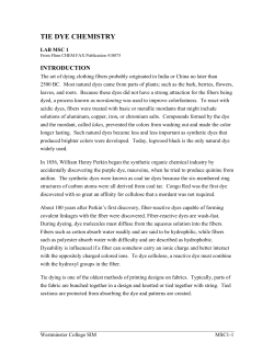
Ocean Inversion Project
How-to-Document Version 1.0
May 27, 2003
Fletcher, Sara E., Nicolas Gruber, and Andrew R. Jacobson
Table of Contents
1. Introduction
2. Input Files
2.1
2.2
2.3
2.5
Region mask
Spatial Pattern
Atmospheric CO2 Mixing Ratio
Downloading Input Files
3. Model Runs and Generation of Green's Functions
3.1 Initial Concentrations
3.2 Quasi-stationary state
3.3 Time-dependent
4. Output
4.1 Output Routines
4.2 Compiling Output Routines
4.3 Using Output Routines
5. Transferring Output
6 . Helpful Links
7. Contacts
8. How to Cite this Document
9. Bibliography
1
1. Introduction
High quality, quantitative estimates of air-sea CO2 flux are critical to interpreting
atmospheric CO2 concentration gradients, understanding the global carbon cycle, and
predicting climate change. However, significant uncertainties about ocean carbon uptake
and the mechanisms that control it persist. Recently, and ocean inverse technique has
been explored to estimate preindustrial and anthropogenic ocean CO2 exchange using
observations of DIC and other trace species in the oceans (Gloor et al., 2003, Gloor et al.,
2001) following an inverse technique originally designed to estimate CO2 fluxes from
atmospheric data (Enting and Mansbridge, 1989, Keeling et al., 1989; Fan et al., 1998.)
In this technique, ocean transport is described by a series of model-generated basis
functions that represent the impact of a unit flux of a dye tracer into a discrete region of
the ocean on the concentration of that tracer throughout the ocean.
Comparisons between inverse estimates using three different versions of an ocean
general circulation model (OGCM) suggest that uncertainty associated with model
transport error is the largest source of error in the ocean inversion (Gloor et al, 2003).
The goal of this project is to quantify the robustness and uncertainties of this method by
employing Green's functions from a variety of different OGCM's. This how-to
document contains all of the information needed to generate dye patterns for this OGCM
basis function comparison.
The ocean surface area will be divided into thirty ocean regions, with an option to use
sixteen ocean regions instead if the thirty region scenario requires a prohibitive amount of
computation time for some modelers. Then, a constant unit flux will be emitted from
each dye region distributed spatially within the region according to the climatology of
Takahashi et al. (2002). Two different dye simulations will be conducted. First, for a
time-independent inversion, the dye tracers will be integrated forward until quasi-steady
state is reached, when the dye concentration is increasing at the same rate throughout the
ocean. Then, for a time-dependent inversion, the dye will be integrated forward from
1765-2005. In the time-dependent case, the dye flux will be weighted by the atmospheric
mixing ratio of CO2 to account for changing oceanic CO2 uptake associated with
anthropogenic perturbations of atmospheric CO2.
Once the Green's function integrations are complete, the inversions will be completed
centrally at UCLA, according to the method described previously (Gloor et al. 2001,
Gloor et al., 2003). Since the majority of the modelers participating in this project also
contributed to the Ocean Carbon-Cycle Model intercomparison Project (OCMIP), this
document and the data files and programs that accompany it generally follow those
designed for the OCMIP project.
2. Input Files
2
2.1 Region mask
Figure 1. Proposed model region masks. Top: the preferred thirty region mask,
labeled with region codes from Table 1. Bottom: the alternative sixteen region option
with region labels describing how the thirty regions have been combined to form 16
regions. Boundaries of the ocean regions used in the TransCom model
intercomparison experiment are shown in black, with the additional boundaries
included for the ocean inversion project shown in red.
The netCDF file 30reg_regionmask.cdf defines the thirty ocean model regions that
3
should be used for the thirty tracer dyes, shown in Figure 1 (top). This file consists of
thirty spatial maps where grid boxes inside the model region are set to 1 and those outside
the region are set to 0. While the thirty ocean region scheme is strongly preferred, we
recognize that integrating this number of dye tracers may not be feasible for some groups.
Modelers who find this prohibitively computationally expensive may instead use the 16
region mask shown in Figure 1 (bottom), 16reg_regionmask.cdf. Both region masks
were designed to be compatible with the 11 ocean regions employed in the TransCom
model intercomparison project (Gurney et al., 2000) in order to allow for comparisons
between the two studies. The Fortran program read_mask.f is provided as an example of
how to read these files. The exact region boundaries for the thirty and 16 region
scenarios are shown in Tables 1 and 2 respectively.
When interpolating region masks to differing model grids, some model grid cells may
straddle two regions. We prefer a 'hard boundary' approach to this problem in which
straddling model grid cells should be assigned to the region that contains the majority of
the volume of the grid cell. The region mask, M, should be set to 0 for grid cells outside
the model region and 1 for grid cells inside the model region:
M i,j
Mask 1,0
Eq.1
Due to differences between model grids, some differences between region areas are
expected; however, the area of the interpolated model regions should not deviate from the
original region areas by more than 10%.
Table 1. Description of thirty model regions
Region Region
Location
Number Code
Region Boundaries
1
NOCN
Arctic Ocean
North of 75.595 N
2
NAH
North Atlantic
48.901 N - 75.595 N
3
NAM
North Atlantic
35.563 N - 48.901 N
4
NAL
North Atlantic
17.781 N - 35.563 N
5
NAT
North Atlantic
0.000 - 17.781 N
6
SAT
South Atlantic
17.781 S - 0.000
7
SAL
South Atlantic
31.117 S - 17.781 S
8
SAM
South Atlantic
44.455 S – 31.117 S
9
SAH
South Atlantic
57.794 S – 44.455 S
10
SOCN
Southern Ocean
South of 57.794 S
4
Region Region
Number Code
Location
11
NPHW
North Pacific
12
NPHE
North Pacific
13
NPK
North Pacific
14
NPLW
North Pacific
15
NPLE
North Pacific
16
NPTW
North Pacific
17
NPTE
North Pacific
18
SPTW
South Pacific
19
SPTE
South Pacific
20
SPLW
South Pacific
21
SPLE
South Pacific
22
SPMW
South Pacific
23
SPMC
South Pacific
24
SPME
South Pacific
25
SPH
South Pacific
Region Boundaries
North of 48.901 N
West of 195.000 E
North of 35.563 N
East of 195.000 E
Kuroshio Extension
17.781 N – Kuroshio Extension
West of 195.000 E
17.781 N - 35.563 N
East of 195.000 E
0.000 - 17.781 N
West of 198.75 E
0.000 - 17.781 N
East of 198.75 E
17.781 S - 0.000
West of 198.75 E
17.781 S - 0.000
East of 198.75 E
31.117 S - 17.781 S
West of 232.5 E
31.117 S - 17.781 S
East of 232.5 E
44.455 S – 31.117 S
West of 247.5 E
44.455 S – 31.117 S
East of 247.5 E and West of 277.5 E
44.455 S – 31.117 S
East of 277.5 E
57.794 S – 44.455 S
5
Region Region
Number Code
Location
Region Boundaries
26
NI
North Indian
North of 0.000
27
SIT
South Indian
17.781 S - 0.000
28
SIL
South Indian
31.117 S - 17.781 S
29
SIM
South Indian
44.455 S – 31.117 S
30
SIH
South Indian
57.794 S – 44.455 S
Table 2. Description of alternative 16 region scenario
Combination
Region
of thirty
Location
Number Region Model
Regions
Region Boundaries
1
NOCN + NAH
Arctic Ocean
+North Atlantic
Arctic Ocean + North of 48.901 N in the
Atlantic
2
NAM
North Atlantic
48.901 N - 75.595 N
3
NAL
North Atlantic
35.563 N - 48.901 N
4
NAT+SAT
North Atlantic+
South Atlantic
17.781 S -17.781 N
5
SAL+SAM
South Atlantic
44.455 S- 17.781 S
6
SOCN+SAH+
SPH+SIH
Southern Ocean
South of 44.455 S
7
NPHW+NPK
North Pacific
(Kuroshio
Extension)
North of 48.901 N, West of 195.000 E
8
NPHE
North Pacific
9
NPLW
North Pacific
10
NPLE
North Pacific
and the Kuroshio Extension
North of 35.563 N
' East of 195.000 E
17.781 N – Kuroshio Extension
West of 195.000 E
17.781 N - 35.563 N
East of 195.000 E
6
Combination
Region
of thirty
Number Region Model
Regions
Location
Region Boundaries
17.781 S - 17.781 N
11
NPTW+SPTW
North Pacific +
South Pacific
12
NPTE+SPTE
North Pacific +
South Pacific
13
SPLW+SPMW
South Pacific
14
SPLE+SPME+
SPMC
South Pacific
15
NI + SIT
Indian Ocean
North of 17.781 S
16
SIL + SIM
Indian Ocean
44.455 S - 17.781 S
West of 198.75 E
17.781 S - 17.781 N
East of 198.75 E
31.117 S - 17.781 S, West of 232.5 E and
44.455 S – 31.117 S, West of 247.50 E
31.117 S - 17.781 S, East of 232.5 E and
44.455 S – 31.117 S, East of 247.50 E
2.2 Spatial Pattern
The flux for each dye should be distributed spatially according to the CO2 flux
climatology of Takahashi et al. (2002) based on the Wanninkhof parameterization of airsea gas exchange. The monthly mean exchange can be found in the netCDF file
taka02_monthly.cdf. This ocean CO2 flux field has been extrapolated to cover land
regions in order to prevent errors in the interpolation of coastal grid boxes resulting from
differing land-sea masks. The program read_taka.f is provided to read this file.
Once the CO2 flux field has been interpolated to the appropriate model grid, one
creates a spatial pattern, P. P is defined as the magnitude of the monthly CO2 flux, F, for
each grid cell of area, A, within the model region, divided by the total annual flux from
that model region.
M i , j F i , j ,t A i , j
P i , j ,t 1 year
i
j t
M i,j
F i , j ,t
A i,j
0
Eq. 2
Please insure that for all model regions, the annual sum of the spatial pattern the model
grid is equal to one.
7
i
1 year
j
t
P i , j ,t
1
0
Eq. 3
Figure 2. Annual mean CO2 ocean fluxmap in units of mol m-2 yr-1 based on the
climatology of Takahashi et al. (2002). The thirty dye boundaries are superimposed over
the spatial pattern.
2.3Atmospheric CO2 Mixing Ratio
The atmospheric CO2 values are divided into two files. First, splco2_mod.dat
contains a spline fit to ice core and Mauna Loa observations of atmospheric CO2 from
1765 to 2001. This file has been updated from the original OCMIP file splco2.dat file to
include more recent Mauna Loa observations for 1990-2001. The second file,
cis92a_mod.dat, contains projected values for atmospheric CO2 from 2001-2010 from the
IPCC scenarioIS92a representing a 'business as usual' projection of anthropogenic CO2
emission. This scenario over-estimated the increase of atmospheric CO2 in the 1990's, so
the offset between the original OCMIP file cis92a.dat and the NOAA-CMDL Mauna Loa
observations at the year 2001 has been subtracted to reflect recent trends in atmospheric
CO2.
8
The atmospheric CO2 files are text files, and the OCMIP routine read_co2.f is
provided to read them. In addition, c_interp.f can be used to interpolate these data to the
appropriate model time steps and try_c_interp.f illustrates how c_interp.f can be used.
Figure 3. Comparison of the adjusted spline fit of Mauna Loa and ice core data (black
line) and the adjusted IS92a projection (red line) with the NOAA-CMDL Mauna Loa
monthly mean observations for the 1990's (green points).
2.4 Downloading Input Files
These files can be downloaded from the ocean inversion project website
(http://quercus.igpp.ucla.edu/OceanInversion) or by anonymous ftp using the following
commands:
1.
2.
3.
4.
5.
6.
ftp quercus.igpp.ucla.edu
user: anonymous
password: <your full e-mail address>
cd fletcher/ocean_inversion_input
binary
mget takahashi/*
9
7. mget region_mask/*
8. mget atm_co2/*
9. mget write_netCDF/*
10.mget sample_code/*
3. Model Runs and Generation of Green's Functions
Two basis function integrations will be performed. First, in order to estimate the preindustrial carbon sources, the basis functions will be integrated until they reach quasistationary state. Then, to estimate the present-day carbon sources, annually averaged
time dependent basis functions will be calculated. Sample code to demonstrate the
calculations discussed here has been provided.
Modelers are invited to use their currently preferred ocean circulation model;
however, an important component of this study will be the comparison of the ocean
inversion results with the corresponding OCMIP-2 forward model simulation results.
Therefore, modelers who choose to use a model version with different transport from that
used for the OCMIP-2 simulations are strongly encouraged to submit results from the
anthropogenic (hist) and natural (biotic) simulation for their new model version
following the OCMIP-2 How-to documents (Najjar et al., 1999, Orr et al., 1999).
3.1Initial Concentration
Within some model regions, the provided spatial distribution includes both uptake and
emission of CO2, which lead to negative concentrations of the tracer dye early in the
model simulation. If you model is not able to deal with negative concentrations, the dye
concentration should be initialized to a uniform concentration of 1.0 mol/cm3. Before
writing the dye concentrations, this initial dye concentration should be subtracted.
3.2 Quasi-stationary State (Pre-industrial)
For the time-independent inversion to estimate preindustrial fluxes, a constant dye
flux, Ftot, of 1.0 x 10¹⁸ mol/yr is released from each model region. This dye flux should
be distributed spatially within each model region for each month according to the
climatology of Takahashi et al. (2002) discussed in section 2.2. The model is integrated
forward in time until it achieves quasi-stationary state, which is when the dye
concentration increases at the same rate throughout the entire ocean. The model run
should be terminated either after 3000 years or when a the dye concentration in the
10
deepest vertical grid box increases at the same rate as the surface concentration to within
1.0% for am arbitrarily selected point in the Pacific Ocean, 180 º E, 40 º N.
The dye flux for each model grid box in mol cm-2 yr-1, Fdye, is equal to the total dye
flux, Ftot, multiplied by the spatial pattern of the flux, P, divided by the pattern-weighted
area of the model region, A.
F tot P i , j , t
F i , j , t dye 1 year
i
j
t
P i , j ,t
A i,j
0
Eq. 4
3.3 Time-dependent
For the time-dependent case, the model should be integrated from 1765 to 2005. As
for the quasi-stationary case, the Takahashi pattern is used to describe the sub-regional
distribution of the dye flux, but it should be scaled according to the temporal evolution of
the atmospheric CO2 provided in the input files splco2_mod.dat and cis92a_mod.dat,
following the OCMIP 2 experiment. This scaling is based on model results showing that
ocean uptake history is proportional to the atmospheric CO2 perturbation. From 17652001, the spline fit of ice core and Mauna Loa observations is provided in
splco2_mod.dat should be used to represent atmospheric CO2. After that, the future
projection in cis92a_mod.dat should be applied. Thus, the time dependent dye flux can
be written as:
F tot P i , j , t t
F dye i , j , t 1 year
i
j t
P i , j ,t
A i,j
0
Eq. 5
Where ф is the anthropogenic perturbation of atmospheric CO2, equal to the atmospheric
mixing ratio of CO2 at time, t, minus the preindustrial mixing ratio.
t
CO 2
atm
CO 2
preindust
Eq. 6
4. Output
All model output must be provided following standard GDT netCDF format in order
11
to be included in this project. The GDT netCDF standard defines a set of conventions to
facilitate the exchange of climate data. More information about the GDT netCDF
conventions are available on the web at: http://www-pcmdi.llnl.gov/drach/netCDF.html.
Routines are provided to write the required output in a standardized fashion. The output
routines can be obtained by anonymous ftp as described in section 2.4 from the directory
/fletcher/ocean_inversion_output.
All model output should follow the OCMIP output conventions:
Conventions
1. Longitudes must be expressed in degrees as eastward positive (e.g., 120W is to be
expressed as -120; 120E is to be expressed as +120).
2. Latitudes must be expressed in degrees as northward positive. (e.g., 90S is to be
expressed as -90; 90N is to be expressed as +90).
3. Depth must be expressed in meters as positive downward (e.g., the depth of 1000 m is
to be expressed as 1000).
4. For irregular model grids which must be stored as a 1-D vector instead of a 2-D array
(e.g., model AWI), you must set jmt=1, and not imt=1.
5. You must provide model output on a grid without overlapping boxes. For example, if
for longitudes of your model i = 1 is the same as i = imt-1 and i = 2 is the same as i =
imt, then you must only provide model output for values from i=2 to i=imt-1. Future
reference to i during analysis will thus be shifted by one, relative to that used in your
model.
4.1 Output Routines
Physics of the Model: write_nc_MaskAreaBathy.f
write_nc_phys.f
These routines, originally written for OCMIP, write the characteristics of the OCGM
and several key physical quantities in standard OCMIP-2 format. The original OCMIP
version of write_nc_MaskAreaBathy.f wrote the land sea mask, surface area, and model
grid. In addition to these quantities, this version also writes the interpolated region mask
and the surface area of each model region in order to examine differences in the model
region boundaries on the various model grids, and ensure that these differences are
minimal. Write_nc_MaskAreaBathy.f should be called only once and the beginning of
the model run.
Write_nc_phys.f writes the monthly mean potential temperature, salinity, Eulerian
zonal and meridional velocities, and Eddy-induced zonal and meridional transport
12
velocities. For the quasi-stationary state case, this routine should be called monthly for
the first year of the model simulation, prior to model spin-up, and for the final year of the
model simulation. For the time-dependent simulation, ten-year monthly mean values
should be written at the end of the simulation. In some cases, modelers may not be able
to directly produce 10-year means due to limitations in the maximum allowed job time on
their local systems. If this is the case, simply provide the average of ten one-year
averages.
Basis Functions: write_nc_basisfnctns.f
This routine writes the annual mean basis functions in units of mol m-3. For the timedependent basis functions, it must be called at the end of the year for one out of every 10
years from 1775-1965 and every year from 1970-2005. For the quasi-stationary state
basis functions it must be called once the model has achieved quasi-steady state as
defined in section 3.2. When writing the dye concentrations, please subtract the
initialization concentration.
Diagnostics: write_nc_diag_0D.f
write_nc_diag_2D.f
These routines write several quantities useful for diagnosing problems with the dye
flux calculation, and should be called at the end of the model simulation.
Write_nc_diag_0D.f writes the global mean total dye flux, cumulative dye flux, and
global mean dye concentration calculated at the end each year throughout the model
integration for both the time dependent and quasi-stationary state simulations.
Write_nc_diag_2D.f writes the dye flux and cumulative dye flux, which should be
calculated at every time write_nc_basisfnctns.nc is called.
Error Handling: handle_errors.f
You will also need this OCMIP subroutine to handle errors in the other programs.
4.2 Compiling Output Routines
The output routines are f77 compatible, and can be compiled by:
f77 -C -O -L /usr/local/lib -lnetcdf -I /usr/local/include write_nc_basisfnctns.f
These routines may also be compiled using f90, but you will need the function len_trim.f.
This function returns a character string after neglecting trailing blanks.
13
4.3 Using Output Routines
These output routines should be called, for example, as follows:
call write_nc_basisfnctns.f(“IGPP”, “MOM3”,
.
imt, jmt, kmt, ndyetrac, year, nb_seconds_per_year,
.
array)
Line by line, these are:
1. Your assigned group code and your model name and version number.
2. The model dimensions and number of dye tracers and the year and number of seconds
per month.
3. The model array containing the dye concentrations
Input quantities for each individual output routine are listed in Table 2.
Table 2. Summary of output routines
Output Routine
Input variables
write_nc_MaskAreaBathy.f Tracer Mask
write_nc_phys.f
Units
Land=0; Ocean=1
Surface Area
m2
Bathymetry
m
Region mask, interpolated to model
grid
Within region=1;
outside region=0
Model Region Areas
m2
Potential Temperature
C
Salinity
Net surface heat flux
W/m2
Net surface freshwater flux
m/yr
Eulerian zonal velocity
m/s
Zonal wind stress
N/m2
Eulerian meridional velocity
m/s
Meridional wind stress
N/m2
14
Output Routine
Input variables
Units
Eddy-induced zonal transport velocity m/s
Eddy-induced meridional transport
velocity
m/s
write_nc_basisfnctsn.f
Tracer dye concentration
mol m-3
write_nc_diag_0D.f
Global total dye flux
mol s-1
Global total cumulative tracer flux
mol
Global mean dye concentration
mol m-3
Dye flux
mol m-2 s-1
Cumulative dye flux
mol m-2
write_nc_diag_2D.f
The following files should be generated:
“Group_name_MaskAreaBathy.nc”
“Group_name_Stationary_phys.nc”
“Group_name_Timedep_phys.nc”
“Group_name_Stationary_BasisFCTNS.nc”
“Group_name_Timedep_BasisFCTNS_year_.nc”
“Group_name_Stationary_Diag_0D.nc”
“Group_name_Timedep_Diag_0D.nc”
“Group_name_Stationary_Diag_2D.nc”
“Group_name_Timedep_Diag_2D.nc”
5. Transferring Output
All files should be compressed using either gzip or compress, and then transferred to
UCLA. To transfer your output by anonymous ftp, use the following commands:
1.
2.
3.
4.
5.
6.
ftp quercus.igpp.ucla.edu
user: anonymous
password: <your full e-mail address>
cd incoming/ocean_inversion
binary
mput *.nc
Please note that for the 'incoming' directories no directory listing is possible and files may
be uploaded but not downloaded for security reasons.
15
If the ftp transfer rate is too slow to reasonably transfer your files this way, please write
your files to a tape and mail them to:
Sara Fletcher
Institute for Geophysics and Planetary Physics
University of California, Los Angeles
5839 Slichter Hall
Los Angeles, CA 90025
6. Helpful Links
Model intercomparison Projects:
Ocean Inversion Project
http://quercus.igpp.ucla.edu/OceanInversion
OCMIP
http://www.ipsl.jussieu.fr/OCMIP
TransCom
http://transcom.colostate.edu
Data Format and Visualization:
netCDF homepage
http://www.unidata.ucar.edu/packages/netcdf
netCDF user's manual for Fortran
http://www.unidata.ucar.edu/packages/netcdf/guidef
COARDS Conventions
http://ferret.wrc.noaa.gov/noaa_coop/coop_cdf_profile.html
GDT netCDF Conventions:
http://www-pcmdi.llnl.gov/drach/netCDF.html
16
Ferret
http://ferret.wrc.noaa.gov/Ferret
Tecplot
http://www.amtec.com/
Atmospheric CO2 Data:
NOAA-CMDL Carbon Cycle Group
http://www.cmdl.noaa.gov/ccgg/index.html
7. Contacts
For more information about the ocean inversion project or clarification of
this how-to document, please contact:
Sara Fletcher
Institute for Geophysics and Planetary Physics
University of California, Los Angeles
5839 Slichter Hall
Los Angeles, CA 90025
[email protected]
(310) 206-5445
Nicolas Gruber
Institute for Geophysics and Planetary Physics
University of California, Los Angeles
5853 Slichter Hall
Los Angeles, CA 90025
[email protected]
(310) 825-4772
8. How to Cite This Document
Fletcher, S. E., N. P. Gruber, and A. Jacobson, Ocean Inversion Project How-To
17
Document Version 1.0, Internal Report, Institute of Geophysics and Planetary Physics,
University of California, Los Angeles, CA, 18 pp., 2003.
9. Bibliography
Aumont, O. and J. C. Orr, Injection-HOWTO, Internal OCMIP Report, LSCE/CEA
Saclay, Gif-sur-Yvette, France, 17 pp., 1999.
Enting, I. G., and J. V. Mansbridge, Latitudinal distribution of sources and sinks of
atmospheric CO2: Direct inversion of filtered data, Tellus B, 41, 111-126, 1989.
Fan, S., M. Gloor, J. Mahlman, S. Pacala, J. Sarmiento, T. Takahashi, and P. Tans, A
large terrestrial carbon sink in North America implied by atmospheric and oceanic carbon
dioxide data and models, Science, 202, 442-446, 1998.
Gloor, M., N. Gruber, T.M.C. Hughes, and J.L. Sarmiento, Estimating net air-sea fluxes
from ocean bulk data: Methodology and application to the heat cycle, Global
Biogeochem. Cycles, 15, 767-782, 2001.
Gloor, M., N. Gruber, J.L. Sarmiento, C.S. Sabine, R.A. Feely, and C. Rödenbeck, A first
estimate of present and pre-industrial air-sea CO2 flux patterns based on ocean interior
carbon measurements and models, Geophys. Res. Lett., 30, art. no. 1010, 2003.
Gurney, K., R. Law, P. Rayner, and A.S. Denning, "TransCom 3 Experimental Protocol,"
Department of Atmospheric Science, Colorado State University,USA, Paper No. 707,
2000.
Keeling, C. D., S. C. Piper, and M. Heimann, A three dimensional model of atmospheric
CO2 transport based on observed winds: 4. Mean annual gradients and interannual
variations, in Aspects of Climate Variability in the Pacific and Western Americas,
Geophys. Monogr. Ser. 55, D. H. Peterson (ed.), AGU, Washington D.C., pp. 305-363,
1989.
Najjar, R. G. and J. C. Orr, Biotic-HOWTO, Internal OCMIP Report, LSCE/CEA Saclay,
Gif-sur-Yvette, France, 15 pp., 1999.
Orr, J. C., R. Najjar, C. L. Sabine, and F. Joos, Abiotic-HOWTO, Internal OCMIP
Report, LSCE/CEA Saclay, Gif-sur-Yvette, France, 25 pp., 1999.
Orr, J. C., J.-C. Dutay, R.G. Najjar, J. Bullister, and P. Brockmann, CFC-HOWTO,
18
Internal OCMIP Report,LSCE/CEA Saclay, Gif-sur-Yvette, France, 12 pp., 1999.
Takahashi, T., S.C. Sutherland, C. Sweeney, A. Poisson, N. Metzl, B. Tilbrook, N. Bates,
R. Wanninkhof, R. A. Feely, C. Sabine, J. Olafsson, Y. Nojiri, Global sea-air CO2 flux
based on climatological surface ocean pCO2, and seasonal biological and temperature
effects, Deep-sea Reas. II- Topical Studies in Oceanography, 49, 1601-1622, 2002.
19


© Copyright 2026