
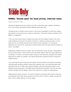
How to Build an Optimist
How to Build an Optimist
How hard can it be, there’s only five bits of
wood; famous last words… The answer is, quite
hard, if you want to build a boat that measures up
to the very comprehensive regulations.
I started by ordering the plans of a “wood/epoxy”
boat from IODA who are in Ireland but need to be
paid in US Dollars! ($56 which is about £30) They
come with a book called “A Guide to building a
wood epoxy Optimist” some of which is useful, but
much of which is at best misleading, at worst plain
wrong. Not that you can tell when you are setting
out on the project.
The book suggests that you build the boat with a
12mm ply bottom and attach the sides to edge of
the bottom, but as the plans have the bottom as
6mm the dimensions for the parts are different.
How good an idea is it to have the instruction
book building a different way to the plans?
Anyway, having done a lot of correction to
dimensions I redrew the plans using my trusty old
2D cad system that is so old no one has ever heard
of it. This resulted in a number of drawings of all
the parts which I took on disc to Cirrus laser
cutters in Burgess Hill, together with the wood,
which I had ordered from Robbins Timber in
Bristol. I used their Robbins Elite which is Gaboon
plywood at 6mm for most parts and 12mm for the
bulkheads and the daggerboard, some parts
needed to be 18mm so I planned to laminate some
12mm and some 6mm to get to 18mm. Of course
wood is never the size it says it is and the 6mm
turned out to be 7mm and the 12mm, 13mm, so
the 18mm laminate is about 20mm !
I had used the services of laser cutting companies
on many occasions before to cut metal
components, but never wood, and I had never
seen it being done. So I asked Cirrus nicely if I
could watch the process, and they agreed. I
actually ended up doing quite a bit more than just
watching, and very interesting it was too. We got
my dxf drawing files onto his computer, re-jigged
the nesting (how the components are placed on
the wood sheet for minimum wastage) and
defined all the start and stop points and the leadins for the laser. If the laser starts on a finished
edge you get a notch, so you start it cutting in a
waste area and lead it in to the component edge.
Once it is underway the process is impressively
fast, and fantastically accurate, to within 0.1mm.
The only problem with it is that it leaves the wood
with a burned edge which then gets on your hands
and onto the face of the wood, needing cleaning
up later.
So now I have a kit of parts. The only problem is
that the edges are all square and some parts need
to be chamfered to a variety of angles. If I was to
do another one I would build this feature into the
cutting and use a five axis cutter which could tilt
the cut as it went.
In addition to all the actual boat parts, the other
important bits you need to cut out are the “mould”
parts. Not strictly a mould, but a pair of formers
that hold the flat bottom of the boat, and the front
and rear transoms in the correct place while the
sides and bulkheads are fitted, together with two
temporary bulkheads which are not glued in, and
are later discarded. I made the mistake of cutting
these temporary parts from 18mm chipboard
which is very heavy and doesn’t stay flat. Next
time I would use cheap plywood, and fit more
braces. To the formers is screwed a mould bottom
which is held at the correct curve by the formers.
The real boat bottom is then held down to that
with some temporary nails or screws, the holes for
which will need filling up later. The front and rear
transoms I had already assembled from some
layers of plywood so that the frames were already
part of the panels. These are then tacked onto the
mould and glued to the boat bottom.
Before all that it is imperative that you make sure
that the former assembly is going to give you a
hull that is the right size and shape. To do that
many hours of studying the measurement form
and the drawings are required. I drew the bottom
datum line onto the formers and marked off all
the measuring points on the line, then checked
that the drop to the underside of the curved hull
bottom former was correct. It was. Then I made
© David Wedge, Burcot Boats | www.burcotboats.co.uk
Page 1 of 4
up a long straight edge to draw the top datum line
on to check the sheerline heights and widths from
later.
Next, in go the mast thwart bulkhead, the midship
bulkhead and the front and rear temporary
frames. All of these need to be dead upright and
held with some bracing until the sides go on.
Fitting the sides is the most tricky bit. I trial fitted
the sides several times, and then finally put the
glue on. The sides were tacked in place with a few
screws, more holes to fill, and some luggage straps
lightly tensioned.
Now is the time to check that the top of the sides
is within tolerance as it is quite easy to move it
about a bit as it is only 6mm ply. If it is left until
the gunwales or the rubbing strips are on it will be
hard to move it. As they were ok, next thing to go
on was the inner gunwale, made up from three
strips of hardwood each side, the inner ones were
from an Ash we felled in Burcot about 12 years
ago, and the others were from some Beech from
Kruzco in Dorchester. These need to be bent into
place and clamped with as many clamps as I could
find and small pads of scrap wood to stop the
clamps denting the wood. So this is where it starts
to take a lot of time, as each of these, and the
outers, eight strips in all, need to be glued on one
at a time and left to go off for 24 hours (eight
days!)
The other time consuming part is to fill all the
holes, imperfections in the wood, gaps in joints,
and put in epoxy fillets. I built the daggerboard
case on the bench, cut the bottom of it to the right
angle, then cut the slot in the bottom of the boat
and glued the case over it, so that the plywood of
the bottom has the smallest possible hole in it.
The booklet says that you should cut out the
bottom so that the case goes right through it, but
this seemed a weaker way to do it to me. The case
is glued to the midship bulkhead, and it has some
framing braces between it and the inside of the
bottom, and seems quite solid. I used some thin
pieces of Beech around the top of the case but I
am not quite happy with that bit yet. The other
thing not to forget at this stage is to seal and
varnish the inside of the daggerboard case before
assembly. I forgot, and it is very tricky to do it
afterwards.
Another slightly tricky bit was made trickier by me
forgetting to cut in the corner braces to the inner
gunwale tops before putting on the outer rubbing
strips, so I had to rout the shape of the braces
down into the gunwale tops avoiding the rubbing
strips, which would have been easy if the strips
had been put on after the braces. The only wooden
part left to fit was now the mast thwart which
needed to be cut to fit as there are no dimensions
for it, apart from the fore to aft length, on the
plans. I was going to leave cutting the mast hole
until later as it is measured from the back of the
boat. It was about now that I removed the
temporary frames and took the hull out of the
form mould for the first time.
It seemed to me that it might be a good idea to see
if the hull was going to be the correct shape before
starting to put the paint finishes onto it, so I
contacted Don O’Donnell who is an official RYA
Measurer, and arranged to take the boat over to
his place in Wootton Bassett for him to measure.
After a very pleasant afternoon with a tape
measure, some jigs and several cups of tea, Don
declared that it was all inside the tolerances.
After any corrections and holes are filled, the next
bit is to start the painting processes. There is a lot
of this! I had glued the boat together with West
System epoxy, which you can use as a clear two
part liquid for close joints and then add filler
powder to it to make up a paste of any consistency
© David Wedge, Burcot Boats | www.burcotboats.co.uk
Page 2 of 4
you need to create fillets or put in joints that are
not so tight. The results had been very good and
strong. The instructions in the West System box
say that you can use it without filler to coat bare
wood and get a good finish, which is what I was
going to do. Luckily I was advised against this, and
I used SP Eposeal which is again a two part epoxy,
but most importantly, it is very thin and the first
couple of coats soak right into the wood. When it
is set, in about 24 hours, the ‘furry’ grain of the
wood is raised and can be sanded off to give a
really nice dull finish. I gave it a further two coats
to fill the grain, each ‘coat’ consisting of three
coats each applied just after the previous one had
gone tacky, then left to go completely hard and
sanded before the next three layer coat. This
leaves a very good base for the paint finish which I
left in the capable hands of my good friend Marvin
who runs TopGun, a paint shop specialising in
Porsche and Ferrari body work. Here it was
painted in some metallic blue left over from a local
Formula One team’s trucks, followed by a gloss
clear coat.
The inside of the hull has had the same Eposeal
primer/filler and then two coats of SP Ultravar
epoxy varnish sanding between.
Both foils are from 12mm ply, the daggerboard is a
simple rectangle, but the rudder is a more
complex shape. The ‘new’ rudder shape having
been only just published by IODA at the time, I
was lucky not to build one to the old shape, as this
will become unusable after March 2005. This was
again redrawn on 2D CAD and this time it was cut
on a CNC router by a woodworking friend. Both
foils were shaped and chamfered to the drawing
specs using a very old, and heavy! belt sander, and
then sealed with Eposeal and varnished with
Ultravar.
All the fittings came from Pinnel and Bax, where
Scott Allen sorted out everything that was needed;
buoyancy bags and straps, toe straps, mainsheet
and blocks, painter (the regulation length is 8
metres, but this is too long for practical purposes
on inland water, but you better have one anyway)
mast step and thwart bearing, rudder pintles and
pins, and some elastic to keep the daggerboard in
place. P&B also supplied the sail and spars.
The difficult part of starting out on the paperwork
trail is actually finding the beginning of the trail.
For a while all the people I contacted said that I
should start with someone else further back, and
even now I don’t think I did it quite correctly. The
problem is that nobody builds their own Optimists
any more. I would now say that that the place to
start is with IOCA. (Area of confusion number 1;
the overall world governing body for the class is
IODA, International Optimist Dinghy Association,
and the National body for the UK is IOCA
International Optimist Class Association. The
confusing part is that the word International is
part of the boat name, “International Optimist”,
and not part of the designation of the
organisation.) Steve Witty, Technical officer IOCA
UK was able to supply the required ISAF sticker
and a blank IODA Registration & Measurement
Book. In this book is a builders fee receipt from
IODA to say that you have paid (via IOCA) the
International Class Fee, and gives you the number
on the ISAF sticker which is to be stuck
permanently on your boat. These cost £18. There
is also a space for the RYA to validate the form
once the boat has been measured. The rest of the
book is the numerous pages of dimensions for the
hull, sail, foils, and spars, all of which will have to
be measured and comply. (Tip; make copies of
these and use them to complete the measurement
process, as each mistake made on the real ones
has to signed off, then get the measurer to fill in
the good originals at the end after any anomalies
have been sorted out.) So the next step is to get
the actual measuring done by a RYA approved
measurer. I found Don O’Donnell who was happy
to do it, and was very helpful with advice. Take as
many bits of the boat with you as possible on the
first trip, as everything will have to be measured in
the end, and make sure you know where all the
serial numbers for the manufactured parts are on
the parts as these will need to be recorded. When
the sail is stamped be careful to roll it back up
with a rag or something over the stamp or the red
ink will get all over the nice new sail! Make sure
that the measurer has filled in every box and
signed every box on every page before you leave.
© David Wedge, Burcot Boats | www.burcotboats.co.uk
Page 3 of 4
The Measurers fee will be in the region of £20,
although they are able to charge £18 per hour
(plus travel if you don’t go to them) for this, but
Don was more than generous with his time, and
tea. The next things you need are from the RYA; a
sail number and a Measurement Certificate. As I
understand it the RYA Measurement Certificate
certifies that the IODA Registration &
Measurement Book is authentic and properly
filled in, and that the measurements it contains
are the correct ones. The sail number allocation
costs £15 and the certificate is another £15. The
completed IODA Registration & Measurement
Book has to go to the RYA together with the fees
(recorded delivery!) and they will send it back all
stamped and filled in and signed. In order to take
part in Optimist races you will have to join IOCA
UK for £25 per year, and make sure the boat is
insured, about £27 per year, and don’t forget to
keep the annual buoyancy test up to date. The
total for paperwork then is £98.
So we now have a tidy new boat, called Skylark,
that is measured and on the weight limit, all that
Hannah and I have to do now is learn how to use
it! It was not the cheapest or easiest way to get
there, but it was a lot of fun, we met some very
friendly and helpful people along the way, and I
have the satisfaction of knowing that I actually
could build a boat to the regs.
David Wedge
August 2004
© David Wedge, Burcot Boats | www.burcotboats.co.uk
Page 4 of 4


© Copyright 2026