
J O T
JOURNAL OF OBJECT TECHNOLOGY
Online at http://www.jot.fm. Published by ETH Zurich, Chair of Software Engineering ©JOT, 2006
Vol. 5, No. 2, March-April 2006
How to align IT with the changes using
UML and according to BMM1?
Applying the “Goal Driven Development” Process on a case study using
UML 2 and the BMM
Birol Berkem, GOObiz / CNAM, Paris - France
Abstract
In the previous articles that I wrote for JOT in 2005 and 2003, I presented the ‘GoalDriven Development Process’ and its patterns that aim at increasing the business
reactivity of the companies in face of changes. In this article, this methodology is
presented using a case study and according to BMM ( The Business Motivation Model voted by the OMG in September 2005).
As you know, use case driven and object-oriented development processes are widely
used in organisations for building their IT systems. This practice allows stakeholders to
concentrate their requirements management efforts as well as analysis and design
efforts on the usage choices of the systems.
However, IT systems developed only with use-case driven and object-oriented
development methodologies do not provide their organisations with good levels of
reactivity in face of changes. This is because these systems are not structured on the
basis of business goals and underlying rules & policies that support the
achievement of these goals, so they are unable to capture changes on the
business needs and propagate them coherently toward IT applications [Align-IT].
In order to show in practice how to develop IT applications on the basis of
company’s goals then align these applications with the changing business rules and
policies, we present below steps of the Goal-Driven Development Process on a case
study using the Enterprise Architect (EA), a UML 2 compliant case tool.
1
The Business Motivation Model [BMM] - Business Governance on a Volatile World voted by the OMG
in September 2005
Cite this article as follows:Birol Berkem: “How to align IT with the Changes using UML and according to
BMM”, in Journal of Object Technology, vol. 5, no. 2, March-April 2006, pp. 85-102
http://www.jot.fm/issues/issue_2006_03/column9
HOW TO ALIGN IT WITH THE CHANGES USING UML AND ACCORDING TO BMM
1 INTRODUCTION
For the last few years, organisations have tried to develop their software systems with use
case driven and object-oriented development processes. This practice does not allow
them to react to changes swiftly and coherently for two main reasons : in use case driven
development
•
business rules are not rendered identifiable as they are often tightly coupled
(mixed) with actor/system interactions in use cases that invoke their behaviours,
• business rules, processes and their IT implementations are not aligned with
company’s goals in order to allow IT applications to be adapted with good levels
of reactivity in face of changes
In order to allow organisations to increase their business reactivity, a Goal-Driven
Development Process becomes necessary for modelling company’s goals, use cases
(usage goals of their “end-users”) that have to invoke courses of action that support these
goals as well as business rules and policies that guide the business in getting there.
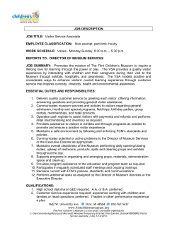
The Business Motivation Model Diagram [BMM] referenced in the figure 1 below
shows such relationships for the Business Governance in a Volatile World. Its basic
elements that are considered as primary by the Goal-Driven Development Process
[Goobiz] are indicated using dashed circles. As shown in the figure, goals as part of the
ends drive courses of actions, directives (rules and policies) and processes.
Steps of the Goal-Driven Development below explain how to instantiate such a chain
till IT components in order to align IT applications with the changes.
86
JOURNAL OF OBJECT TECHNOLOGY
VOL. 5. NO. 2
Figure 1: The Business Motivation Model for a Business Governance in a Volatile World [BMM] of the Business
Rules Group voted by the OMG in September 2005
According to these elements of the Business Motivation Model and their relationships
(indicated using dashed circles from left to right), the Goal-Driven Development Process
(GDDP) allows stakeholders to:
•
discover use cases that are tailored on the requirements according to business
goals (indicated as parts of the desired results on the left)
• establish a bridge between goals and IT architectures that carry out
implementations of their courses of actions and directives using object
components
• trace impacts of the changes captured on requirements till their software
implementation level in order to improve agility of their organisations to react to
changes
The next section shows steps of the Goal-Driven Development Process that accompany
software implementation of the business requirements captured on the basis of goals
throughout courses of actions and business rules & policies that govern them. These steps
VOL. 5. NO. 2
JOURNAL OF OBJECT TECHNOLOGY
87
HOW TO ALIGN IT WITH THE CHANGES USING UML AND ACCORDING TO BMM
are explained on examples of solutions for a case study where one of the high-level goals
of the company is fixed to be “turning its internet visitors into buyers”.
2 STEPS OF THE PROCESS
The Goal-Driven Development Process (GDDP) using UML is constituted of six main
steps. An insight of these generic steps is presented below.
Goal-Driven Development with UML
1. LIST REQUIREMENTS
REQUIREMENTS BY GOALS
1. GROUP
Step 4 - Specify responsibilities of participants for achieving
interactions between and within business processes
Responsibility :
GROUPED BY GOALS
V0 -G8 : Turn Visitors to Buyers by Promoting Products via the WebSite : Present Informations on
Products, Register Visitors, Turn them to potential buyers
WebSite [Turn to buyer]
{ Present company, Promote product, Turn visitor to buyer}
8.1.1
Means :
G8.1 : Present Information on the Company and Products :
8.3
G8.1.1 :Present commercial descriptions on the company using informations from Mktg and Sales
G8.1.2 :Present commercial and technical descriptions of its products using informations from..
_Sales_Mgr
[turn to buyer]
[Visitor
Notified]
:Visitor [Registration] {..}
Fill
Notify
G8.2.1
Questionnaire Visitor
Enter
G8.2.3
G8.2.2
Visitor
G8.2.2.1
G8.1.2.a : If Abandon-Rate on visualizing products > y % then review presentation of the product..
8.2
G8.1.3 : Motivate visitors to register
G8.1.4
Keep ss
informations
Bu:sine
G o al Cup-to-date
as es for th e C om pa ny
...
B U S I NE S S S Y S T E M
3.
MONITOR
ADVANCEMENT
G8.2.1 : Enter Visitor
IN THE REALIZATION
G
G
G8.2.2 : Fill Questionnaire
G8.2.2.a : If Abandon-Rate
P re sen>t x%, review questionnaire of the product ..
OF THE GOALS
S a le s
Tu rn V isito r
C om p a ny o n th e W e b
na g er
to B u manager
ye r
G8.2.3 : Send Notification to the visitor by e-mail and notify sales
in order Mtoaturn
the Visitor to
(OPTIONAL)
Buyer)
W e b Site S yste m
:Visitor [Turn to Buyer]
:Company_Info[Presentation]
G8.2 : Register Visitor {Goal-Value = 50Lregistrants
a week}
A Y ER
8.1.2
[bonus
critical rate
reached ]
:Product_Info[Presentation]
:Bonus
[to review]
8 .1 .1
8.3
8 .1 .2
8.2
[a ba n d on
r ate> y% ]
G
_Mktg_Emp
[questionnaire review]
INSIDE:Prod_Presentation
GOAL-CASES
[Review]
4. ASSIGN RESPONSIBILITIES
PTAL : Plug-in components and prototype their execution
BUSINESS SYSTEM
TO PARTICIPANTS
2. FORMALIZE
WebSite_Mngt [Turn to Buyer] {Motivate Visit ors to Register with a Bonus System}
<<invokes>>
[register]
BEHAVIORS
INSIDE
S tep 4- For m alize in teractio n s be tw een process es
PROCESSES
W ebSite [Turn to buyer]
Visitor [Registration] {with a Bonus System
Company
[Presentation]
Visitor
<<Business Use Case>>
Visit Company
Presentation
R evie w
Q u e stion na ire
R evie w
P ro du ct Pre se nt at io n
{with a Bonus System}
Visitor
[Entry]
Visitor
<<Business Use Case>>
Register Visitor
8.3
[end register]
Visitor
[Registration]
I_Register_Visitor
8 .1 .1 .a
Product_Info
[Presentation]
Goal-value = 100 regist rant a week..}
{Promote
Registration
with a Bonus System..}
<<invokes>>
{ Present co mpa ny, Pro mote prod uct, Turn visitor to buye r}
[notified]
[not winner]
[visitor
entered]
[question. Questionnaire
[Filling]
filled]
I_Mng_Visitor
Visitor
[Notification]
: V i si t o r [T u r n to B u y er ]
_Sales
[turn to buyer]
[bonus critical
rate reached ]
Mktg_[Lottery Realization]
8.1 .1 .b
8.2
Fill
Q u e st i o n n ai r e
Enter
G 8. 2. 2
V i s it o r
N o t if y
V i s it o r
G 8. 2. 3
6. INTEGRATE APPLICATION
: P r od u c t _ In f o [ P re s e n t at i o n ]
CONSTRAINTS OF THE
ACTORS
G 8 .2 .2.1
8 .1 .1 .b .1
8 .2.2.1
[a ba nd o n
r at e> x% ]
:Q u esti o n na ire
[to re vi ew ]
: P r od _ Q u e st i o n n ai r e
[ R e vi e w ]
:P res enta ti on
[to re vi ew ]
to be plugged
into
<<BUC_Comp>>
Visitor[Entry]
V isito r [P r o d R e g ist ra tio n] {..}
G 8. 2. 1
{Goal-value <1 winner
/100 registered visitor}
to be plugged
into
[a ba n d o n
r at e> y% ]
: P r od _ P r e se n t a t io n
[ R e vi e w ]
C
O
D
E
+enter_visitor ()
-fill_form()
-complete_fields()
-thanks_for_entry()
-cancel_entry()
-...
UC1
Visitor[Entry]
+enter_visitor ()
-process_entry() {PRE=..}
-check_form() {PRE=..}
-ask_to_complete() {PRE=..}
-register_form() {PRE=..}
-cancel_entry() {PRE=..}
UC2
:GOO:GOO
I_ Present
Product
Sales [Turn to
Buyer]
I_Make_Buyer
Bonus
[As signment]
{Goal-value = 1 winner /100}
Lottery [Realize]
:V is i tor
[N o tifi ed ]
C o m pa n y _ I nf o [ P r es e n t a ti o n ]
8.1.2.a
[abandon
rate> y%]
4. FORMALIZE BEHAVIORS
V isit or
G
_Sales_Emp
[bonus review]
:Questionnaire
[Review]
8.2.2.a
[a ba n d on
r ate> x% ]
:Presentation
[to review]
:Questionnaire
[to review]
e nd
re gistrati o n
visitors toGpotential buyers …
MG8.3
a rket:inTurn
g
G
information to registered visitors about evolutions on the products..
Send
M
a na gregularly
er
P re sen t Pro d uct s
R eg iste r V isito r
o n th e W eb
8.1.2.a
8.2.2.a
[abandon
rate> x%]
Sales [Bonus
Review]
Visitor
[Turn to
Buyer]
[Min. s tocks
reached]
_Sales
[bonus review]
[winner_rate > 1/
100]
Lottery_Rules
[Review]
_Mktg
[lottery review]
Purchase
[Material
Order]
Material
I-Purchase [Purchase]
_Purchase
[material order]
5. PLUG BEHAVIORS IN THE
ARCHITECTURE & PLAY
GOObiz.com
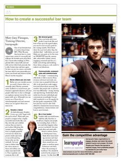
Figure 2: Steps of the «Goal-Driven Development» Process with UML
Roles of these steps are as follows:
Step 1 focuses on grouping requirements by goals, setting objectives that quantify
them as well as modelling goals and use cases that invoke them.
Step 2 is interested on showing courses of action that support the previous desired
results as well as business rules and policies that govern these courses of action
88
JOURNAL OF OBJECT TECHNOLOGY
®
Goal-Oriented Objects
VOL. 5. NO. 2
Step 3 (optional step) set up rules for giving feed-backs to managers for allowing
them to monitor advancement in achieving these goals
Step 4 focuses on business processes that describe possible realisations of these
courses of action by assigning responsibilities to their participants and system
components
Step 5 transforms these goals and rules based specifications in executable software
components and plug-in them into the backbone of the goal-driven business process
architecture
Step 6 integrate application choices of the IT actors in realising their responsibility
according to previous business processes (this step is not covered by the case study)
The examples given below show an application of these steps using the Enterprise
Architect (EA) UML tool.
Step 1 Grouping requirements by goals and showing goal cases of the
system
In this first step, we enter requirements in the system by grouping them according to
company’s goals (Step 1.1) then model them inside high-level goals of the company
(Step 1.2).
Step 1.1 Grouping requirements by goals
For assisting non-technical business experts in capturing changes that arise in the
business system and propagating them within the business layer of the organization in
order to align its underlying structures, requirements have to be grouped using
identifiable goal structures (goal cases).
A goal case is a set of requirements (behaviours for the system) that belong to (or
support) a given goal. Goal cases are described by grouping courses of actions
(behaviours of the system) that support a given goal. They also constitute the essence of
use cases as they make sense to actor / system interactions that permit to realise a
business goal.
The figure 3 below illustrates high-level goals and their underlying parts as well as
requirements (business rules and policies) that have to support their achievement for
making the company website system beneficial by turning its visitors into buyers.
VOL. 5. NO. 2
JOURNAL OF OBJECT TECHNOLOGY
89
HOW TO ALIGN IT WITH THE CHANGES USING UML AND ACCORDING TO BMM
Figure 3: Business rules and policies are first grouped using goals in order to determine business goal cases
In the next step, we model these goal cases and discover eventually their possible
participants (actors) and use cases that have to participate to their realisation. Notice that
potential participants and use cases that have to participate to the realisation of goal cases
may also be found in the step 4 of the GDDP that focuses on the potential realisation
scenarios for achieving business goals.
Step 1.2 Model Goal Cases then discover potential actors and use cases
In order to confer coherent and swift evolution to the desired results till their IT
implementation, previous requirements captured by goals must be rendered visible. Such
a visibility of the goals requires from them to be identified separately (without being
mixed with usage choices of their actors). In this perspective, we model them using
business goal cases.
The figure 4 shows high-level goals of the business system (represented via
boundaries) with their underlying goal cases based on the previous requirements. Such
goal boundaries allow business goal cases with their supporting business rules and
90
JOURNAL OF OBJECT TECHNOLOGY
VOL. 5. NO. 2
policies (included inside them) to evolve coherently in respect to these higher-level goals
in face of changes.
Figure 4: A draft of the architecture of the high-level business goals and goal cases for the “Beneficial website system”
On the basis of these specifications, components of use cases (indicated in yellow in the
figure 5 below) are determined to represent corresponding goals of the participants
(actors) in using these business goal cases. These actor’ goals have, in turn, to be
supported by courses of actions related to actor / system interactions that are necessary
for realising business goal cases (see step 4.2).
VOL. 5. NO. 2
JOURNAL OF OBJECT TECHNOLOGY
91
HOW TO ALIGN IT WITH THE CHANGES USING UML AND ACCORDING TO BMM
Figure 5: A draft of the desired results (goal cases) and corresponding actor’s usage intentions (use cases) for the
“Website system”
Step 2 Formalise behaviours (courses of actions with appropriate business
rules and policies) then draft the «architectural backbone» of the system
This step allows us to formalise courses of actions that channel efforts toward supporting
the previous business goal cases. Along these courses of action, business rules and
policies are formalised between and within actions.
We describe in figure 6 courses of actions that realise business goal cases defined in
the previous step. In order to keep traceability with high-level goals of the system,
courses of actions that support business goal cases are described within the same goals.
These courses of actions are illustrated below using UML activity stereotypes,
control flows, conditions, etc…
92
JOURNAL OF OBJECT TECHNOLOGY
VOL. 5. NO. 2
Figure 6: Cartography of courses of actions and business rules / policies that support desired results for the ‘Website
System’
At this stage, the cartography of courses of actions enriched by the rules and policies may
be used as a basis to generate components of the architectural backbone of the system in
order to early test its high-level behaviours. The resulting architecture would provide us
with the components and rules illustrated in figure 9, except behaviours of the system
related to the communication with its participants discovered next in step 4.
Step 3 (Optional step) Set up rules to monitor advancement in achieving
goals
This optional step allows stakeholders to set up rules for providing them with feed-backs
in order to monitor advancement in achieving previously defined business goals. In order
to help stakeholders for setting up these rules, an initial structure of the high-level
architectural backbone of the system may be used here in order to early prototype the
above specifications.
VOL. 5. NO. 2
JOURNAL OF OBJECT TECHNOLOGY
93
HOW TO ALIGN IT WITH THE CHANGES USING UML AND ACCORDING TO BMM
Step 4 Describe business processes that have to realise courses of actions
by assigning responsibilities to their participants and system components
In this step, we focus on the business processes that have to describe possible
realisations (scenarios) of the previous courses of actions, being governed by the
business rules and policies.
In order to describe precisely realisation scenarios for these courses of action,
responsibilities must be assigned to the participants of the business goal cases as well as
to related system components (from user interfaces till business objects-entities). Thus,
we describe such realisation scenarios using two refinement levels. The step 4.1 presents
high-level descriptions of these realisation scenarios that aim at ensuring communication
between courses of actions described in figure 6 whereas the step 4.2 presents underlying
behaviours of the use case and goal case components that have to collaborate for realising
these scenarios.
Step 4.1 Model responsibilities that have to be assigned to the participants
and the system for ensuring communication between courses of action
The figure 7 below illustrates a realisation scenario that describes responsibilities
assigned to the participants and to the system for ensuring communication between
courses of action specified in figure 6. Communications between courses of action are
modeled using control flows or object flows (when objects have to be produced by an
action and consumed by another action).
For example, according to the business rule R1.2.1.a , if the abandon rate of visitors
is over than 50% while consulting products, the system produces an object flow toward
the Marketing_Mgr in order to incite him/her to review presentation of the products.
The assignment of the responsibility about reviewing products to the Marketing_Mgr
is illustrated by setting his state to Marketing_Mgr [Prod_Review] when the previous
condition becomes true.
Thus, the Marketing_Mgr switches to the state Prod_Review (review of the product)
at the end of the process Consult Products then this new state causes starting of the target
process Review Product Presentation.
94
JOURNAL OF OBJECT TECHNOLOGY
VOL. 5. NO. 2
Figure 7: Description of the responsibilities assigned to the participants and the system for realising courses of action
Step 4.2 Model underlying behaviours of the use case and goal case
components for realising the previous scenarios
In this step, we describe underlying scenarios for the actions of the previous processes
that require actor / system interactions for their realisation. The resulting actions are
distributed as actions for underlying use case and goal case components depending on
their nature (controls for the user interface objects or for the business entity objects, etc).
The below activity diagram illustrates a realisation scenario for the action Enter
Visitor of the process Register Visitor (by clicking on its icon illustrated in figure 7).
Actions of the underlying use case and goal case components - that respectively handle
user interface objects (on the left) and entity objects (on the right) are described within
corresponding partitions. The final photos that are desired in term of state changes such
as [created], [validated], [linked to visitor], [sent], etc.. are illustrated under these
objects in order to guide developers about states that must be reached by these objects in
VOL. 5. NO. 2
JOURNAL OF OBJECT TECHNOLOGY
95
HOW TO ALIGN IT WITH THE CHANGES USING UML AND ACCORDING TO BMM
the related actions. These states are indicated as comments in the generated source code
(see figure 11) for helping developers in implementing corresponding methods.
Figure 8: Behavioral description of the components of use cases and goal cases that realise the action Enter Visitor of
the business process Register Visitor
Step 4.3 Draft the architectural backbone of the system using use case and
goal case components
In this stage, a second draft of the goal-driven architectural backbone of the system may
be generated for early testing system behaviours. Use case (UC) and goal case (GC)
components of the system are specified with their interfaces. These components have to
host software level behaviours related to business rules, actor/system interactions, etc that
will be transformed into object-oriented specifications in the following step based on the
above. The figure 9 below shows such an initial structure of the architectural backbone
with its use case and goal case components and responsibilities assigned to participants.
96
JOURNAL OF OBJECT TECHNOLOGY
VOL. 5. NO. 2
Figure 9: The Goal-Driven Architectural Backbone of the WebSite System with its basic components
Step 5 Plug-in the business behaviours into the architectural backbone and
play
This step requires transformation of the use cases and goal cases behaviours -described in
figure 8- using object-oriented specifications such as classes, attributes, methods,
constraints of pre/post conditions, etc… in order to plug-in them finally into their parent
components in the architectural backbone.
Step 5.1 Transform functional representations of the specifications into
their object-oriented representations
In order to be plugged into the architectural backbone of the system, the above
specifications that are related to user interfaces, use cases, goal cases and entity objects
are transformed into their corresponding object oriented specifications. In this
perspective, conditions and actions described for use case and goal case components (of
VOL. 5. NO. 2
JOURNAL OF OBJECT TECHNOLOGY
97
HOW TO ALIGN IT WITH THE CHANGES USING UML AND ACCORDING TO BMM
the figure 8) are respectively transformed for giving corresponding attributes and
methods as well as for specifying pre-conditions of these methods (figure 10 below).
The below class diagram shows description of the business use case (BUC) and goal
case (BGC) classes for Visitor_Entry on the basis of the previous specifications (figure 8)
with the user interfaces (UI) and entity objects (Data Model) they have to handle.
Figure 10: Internal structure of the components of Use Cases and Goal Cases to be plugged into the architectural
backbone of the system
The underlying behaviours of these actions (user interface and entity object handling, etc)
that are expressed using specifications (such as conditions, final states for objects) are
also transformed into O.O specifications. Such an early transformation permits to
prototype specifications of the business experts and to guide designers to complete them
by technical aspects for their unit and integration tests. The print screen of the figure 11
below shows correspondence between actions specified for the component of goal case
Visitor_Entry and their corresponding method body in the Java code on the right. This is
just an initial ‘mono user’ version of the code that is elaborated for early testing these
98
JOURNAL OF OBJECT TECHNOLOGY
VOL. 5. NO. 2
actions. For a final multi-user version, method declarations have to be setting up as nonstatic and components of use case and goal case of the figure 10 have to be instantiated.
Figure 11: Transformation in Java of the courses of actions for Enter_Visitor
5.2 Plug-in the use case and goal case behaviours into the architectural
backbone
After their unit testing, use case and goal case components are plugged into appropriate
structures of the architectural backbone of the system for their integration test with the
other components of the system.The figure below illustrates the plug-in of the previous
components into the system architecture using a simple “plug and play” mechanism.
VOL. 5. NO. 2
JOURNAL OF OBJECT TECHNOLOGY
99
HOW TO ALIGN IT WITH THE CHANGES USING UML AND ACCORDING TO BMM
Figure 12: Components of use cases and goal cases are plugged into their appropriate parent components within the
goal-driven architectural backbone of the system
Thanks to its goal-driven and component based architecture backbone that allows
traceability of the requirements (business rules, policies) captured on the goal basis till
their implementation level, the Goal-Driven Development Process makes easier
adaptation of these components to the changes. Indeed, changes captured on the business
rules and policies using the goal-driven development framework are propagated till their
lower-level courses of actions that in turn are implemented by underlying use case and
goal case components.
3 CONCLUSION
Solutions presented for implementing business rules given at the figure 3 illustrate how
to specify these rules step by step on the basis of company’s goals using the GoalDriven Development Process [Align-IT] and according to the Business Motivation
100
JOURNAL OF OBJECT TECHNOLOGY
VOL. 5. NO. 2
Model [BMM] in order to align IT applications with changes captured on these
business rules.
Thanks to the separation [Visibility of the Rules] of the business goals from their
usage scenarios (use cases) and to its architecture based on goal-oriented object
components, the «Goal-Driven Development» process provides its users with means that
allow them to adapt their IT applications to the changes swiftly and coherently
[GDDP4MDA].
By carrying these principles at the organisational level, the infrastructure of the
GDDP [Goobiz] helps organisations to enhance continuously their business processes
in order to increase their business reactivity without worrying about alignment of their
IT applications.
Copyright © 2005 - 2006 Goobiz.com - Birol Berkem
REFERENCES
[BMM]: Business Motivation Model - Business governance in a volatile world of the
Business Rules Group voted by the OMG in September 2005
http://www.businessrulesgroup.org/second_paper/BRG-BMM.pdf ,
[Visibility of the Rules]: Stan Hendryx - Business Rules - BPTrends / BPT
http://www.businessprocesstrends.com/publicationfiles/Hendryx%2Epdf,
October 2004
[Semantic Web]: John Hall , How will the Semantic Web support business? - W3C
Workshop
on
Rule
Languages
for
Interoperability
http://www.w3.org/2004/12/rules-ws/paper/127, April 2005
[GDDP4MDA]: Birol Berkem, Goal Driven Development for MDA – OMG’s Technical
Meeting in Athens http://www.omg.org/cgi-bin/doc?omg/2005-04-05, April
2005
[Align-IT]: Birol Berkem, Aligning IT with the Changes using the Goal-Driven
Development for UML and MDA - Journal of Object Technology, vol. 4, no. 5,
July-August 2005 http://www.jot.fm/issues/issue_2005_07/column5
[Goobiz]: How to increase your business reactivity with UML and MDA? (White paper
on
the
Goal-Driven
Development
Patterns
and
Processes)
http://www.goobiz.com/GOObizWP/GOObizWP.htm
VOL. 5. NO. 2
JOURNAL OF OBJECT TECHNOLOGY
101
HOW TO ALIGN IT WITH THE CHANGES USING UML AND ACCORDING TO BMM
About the author
Birol Berkem is a consultant and trainer in the areas of business and application system
analysis and design with the object technology. He is the author of the “Goal-Driven
Development” patterns and frameworks for aligning IT with the changes using UML and
MDA. His e-mail address is [email protected]
102
JOURNAL OF OBJECT TECHNOLOGY
VOL. 5. NO. 2


© Copyright 2026