
HOW TO USE THIS MANUAL GENERAL INFORMATION
IN--1 INTRODUCTION -- HOW TO USE THIS MANUAL HOW TO USE THIS MANUAL IN02D--01 GENERAL INFORMATION 1. INDEX An INDEX is provided on the first page of each section to guide you to the item to be repaired. To assist you in finding your way through the manual, the Section Title and major heading are given at the top of every page. 2. GENERAL DESCRIPTION At the beginning of each section, a General Description is given that pertains to all repair operations contained in that section. Read these precautions before starting any repair task. 3. TROUBLESHOOTING TROUBLESHOOTING tables are included for each system to help you diagnose the problem and find the cause. The fundamentals of how to proceed with troubleshooting are described on page IN--8. Be sure to read this before performing troubleshooting. 4. PREPARATION Preparation lists the SST (Special Service Tools), recommended tools, equipment, lubricant and SSM (Special Service Materials) which should be prepared before beginning the operation and explains the purpose of each one. 5. REPAIR PROCEDURES Most repair operations begin with an overview illustration. It identifies the components and shows how the parts fit together. Example: Oil Pump Body Drive Rotor ×10 Driven Rotor Oil Pump Body Cover z Crankshaft Front Oil Seal Relief Valve Compression Spring N·m (kgf·cm, ft·lbf) : Specified torque z Non--reusable part Plug 49 (500,36) M17080 IN--2 INTRODUCTION -- HOW TO USE THIS MANUAL The procedures are presented in a step--by--step format: S The illustration shows what to do and where to do it. S The task heading tells what to do. S The detailed text tells how to perform the task and gives other information such as specifications and warnings. Example: Task heading : what to do 21. CHECK PISTON STROKE OF OVERDRIVE BRAKE (a) Place SST and a dial indicator onto the overdrive brake piston as shown in the illustration. SST 09350--30020 (09350--06120) Illustration: what to do and where Set part No. Detailed text : Component part No. how to do task (b) Measure the stroke applying and releasing the compressed air (392 -- 785 kPa, 4 -- 8 kgf.cm2 or 57 -- 114 psi) as shown in the illustration. Piston stroke: 1.40 — 1.70 mm (0.0551 — 0.0669 in.) Specification This format provides the experienced technician with a FAST TRACK to the information needed. The upper case task heading can be read at a glance when necessary, and the text below it provides detailed information. Important specifications and warnings always stand out in bold type. 6. REFERENCES References have been kept to a minimum. However, when they are required you are given the page to refer to. 7. SPECIFICATIONS Specifications are presented in bold type throughout the text where needed. You never have to leave the procedure to look up your specifications. They are also found in Service Specifications section, for quick reference. 8. CAUTIONS, NOTICES, HINTS: S CAUTIONS are presented in bold type, and indicate there is a possibility of injury to you or other people. S NOTICES are also presented in bold type, and indicate the possibility of damage to the components being repaired. S HINTS are separated from the text but do not appear in bold. They provide additional information to help you perform the repair efficiently. 9. SI UNIT The UNITS given in this manual are primarily expressed according to the SI UNIT (International System of Unit), and alternately expressed in the metric system and in the English System. Example: Torque: 30 N·m (310 kgf·cm, 22 ft·lbf) IN--3 INTRODUCTION -- IDENTIFICATION INFORMATION IDENTIFICATION INFORMATION ENGINE SERIAL NUMBER IN05L--01 1. ENGINE SERIAL NUMBER The engine serial number is stamped on the engine block, as shown in the illustration. M1UZ Engine M01548 IN--4 INTRODUCTION -- REPAIR INSTRUCTIONS REPAIR INSTRUCTIONS GENERAL INFORMATION 1. (a) (b) FI1066 (c) (d) (e) (f) (g) IN05M--01 BASIC REPAIR HINT Use the protection covers to keep the boat clean and prevent damage. During disassembly, keep parts in the appropriate order to facilitate reassembly. Observe the following: (1) Before performing electrical work, disconnect the negative (--) terminal cable from the battery. (2) If it is necessary to disconnect the battery for inspection or repair, always disconnect the negative (--) terminal cable which is grounded to the engine block. (3) To prevent damage to the battery terminal, loosen the cable nut and raise the cable straight up without twisting or prying it. (4) Clean the battery terminals and cable ends with a clean shop rag. Do not scrape them with a file or other abrasive objects. (5) Install the cable ends to the battery terminals with the nut loose, and tighten the nut after installation. Do not use a hammer to tap the cable ends onto the terminals. (6) Be sure the cover for the positive (+) terminal is properly in place. Check hose and wiring connectors to make sure that they are secure and correct. Non--reusable parts (1) Always replace cotter pins, gaskets, O--rings and oil seals etc. with new ones. (2) Non--reusable parts are indicated in the component illustrations by the ”z” symbol. Precoated parts Precoated parts are bolts and nuts, etc. that are coated with a seal lock adhesive at the factory. (1) If a precoated part is retightened, loosened or caused to move in any way, it must be recoated with the specified adhesive. (2) When reusing precoated parts, clean off the old adhesive and dry with compressed air. Then apply the specified seal lock adhesive to the bolt, nut or threads. (3) Precoated parts are indicated in the component illustrations by the ”L” symbol. When necessary, use a sealer on gaskets to prevent leaks. IN--5 INTRODUCTION (h) (i) Medium Current Fuse and High Current Fuse Equal Amperage Rating (j) -- REPAIR INSTRUCTIONS Carefully observe all specifications for bolt tightening torques. Always use a torque wrench. Use of special service tools (SST) and special service materials (SSM) may be required, depending on the nature of the repair. Be sure to use SST and SSM where specified and follow the proper work procedure. A list of SST and SSM can be found in preparation section in this manual. When replacing fuses, be sure the new fuse has the correct amperage rating. DO NOT exceed the rating or use one with a lower rating. M01367 Illustration Symbol Part Name Abbreviation FUSE FUSE CIRCUIT BREAKER CB BE5594 M05598 (k) (l) Care must be taken when sling up and supporting the engine. Be sure to support the engine at the proper positions (See page IN--7). (1) After the engine is slung up, be sure to support it on stands. It is extremely dangerous to do any work on engine suspended at the sling hook, even for a small job that can be finished quickly. Observe the following precautions to avoid damage to the following parts: (1) Do not open the cover or case of the ECU, ECM unless absolutely necessary. (If the IC terminals are touched, the IC may be destroyed by static electricity.) IN--6 INTRODUCTION WRONG (2) CORRECT (3) (4) (5) IN0253 WRONG (6) CORRECT (7) (8) IN0252 Example IN0002 -- REPAIR INSTRUCTIONS To disconnect vacuum hoses, pull on the end, not the middle of the hose. To pull apart electrical connectors, pull on the connector itself, not the wires. Be careful not to drop electrical components, such as sensors or relays. If they are dropped on a hard floor, they should be replaced and not reused. When steam cleaning an engine, protect the electronic components, air filter and emissions--related components from water. Never use an impact wrench to remove or install temperature switches or temperature sensors. When checking continuity at the wire connector, insert the tester probe carefully to prevent terminals from bending. When using a vacuum gauge, never force the hose onto a connector that is too large. Use a step--down adapter for adjustment. Once the hose has been stretched, it may leak. (m) Tag hoses before disconnecting them: (1) When disconnecting vacuum hoses, use tags to identify how they should be reconnected. (2) After completing a job, double check that the vacuum hoses are properly connected. A label under the hood shows the proper layout. (n) Unless otherwise stated, all resistance is measured at an ambient temperature of 20˚C (68˚F). Because the resistance may be outside specification if measured at high temperatures immediately after the engine has been running measurements should be made when the engine has cooled down. IN--7 INTRODUCTION -- REPAIR INSTRUCTIONS IN05N--01 ENGINE SLING AND SUPPORT POSITIONS Front 59 mm ( 2.3 in.) HINT: To level the engine, move up the rear stands 59 mm (2.3 in.) as shown above figure. SLING POSITION Front Rear SUPPORT POSITION Front Rear Front Engine Hanger Rear Engine Hanger Front Engine mounting Insulator Rear Engine mounting Insulator M01930 IN--8 INTRODUCTION -- HOW TO TROUBLESHOOT ECU CONTROLLED SYSTEMS HOW TO TROUBLESHOOT ECU CONTROLLED SYSTEMS GENERAL INFORMATION IN05Q--01 A large number of ECU controlled systems are used in the M1UZ Engine. In general, the ECU controlled system is considered to be a very intricate system requiring a high level of technical knowledge and expert skill to troubleshoot. However, the fact is that if you proceed to inspect the circuits one by one, troubleshooting of these systems is not complex. If you have adequate understanding of the system and a basic knowledge of electricity, accurate diagnosis and necessary repair can be performed to locate and fix the problem. FOR USING OBDII SCAN TOOL OR TOYOTA HAND--HELD TESTER S Before using the OBDII scan tool or TOYOTA hand--held tester, the OBDII scan tool’s instruction book or TOYOTA hand--held tester’s operator manual should be read thoroughly. S If the OBDII scan tool or TOYOTA hand--held tester cannot communicate with ECU controlled systems when you have connected the cable of the OBDII scan tool or TOYOTA hand--held tester to DLC3, Turned the ignition switch ON and operated the scan tool, there is a problem on the engine side or tool side. (1) If communication is normal when the tool is connected to another engine, inspect the diagnosis data link line (Busline) or ECU power circuit of the engine. (2) If communication is still not possible when the tool is connected to another engine, the problem is probably in the tool itself, so perform the Self Test procedures outlined in the Tester Operator’s Manual. INTRODUCTION -- IN--9 HOW TO TROUBLESHOOT ECU CONTROLLED SYSTEMS HOW TO PROCEED WITH TROUBLESHOOTING IN05P--01 Carry out troubleshooting in accordance with the procedure on the following page. Here, only the basic procedure is shown. Details are provided in the DI section, showing the most effective methods for each circuit. Confirm the troubleshooting procedures first for the relevant circuit before beginning troubleshooting of that circuit. Engine/Boat Brought to Workshop 1 2 1 Ask the customer about the conditions and the environment when the problem occurred. Customer Problem Analysis Symptom Confirmation and Diagnostic Trouble Code Check 3 Symptom Simulation 2, 3 Confirm the symptoms and the problem conditions, and check the diagnostic trouble codes. (When the problem symptoms do not appear during confirmation, use the symptom simulation method described later on.) 4 Diagnostic Trouble Code Chart 5 6 Problem Symptoms Table Circuit Inspection or Parts Inspection 7 Repair 8 Confirmation Test End 4, 5, 6 Check the results obtained in Step 2, then confirm the inspection procedure for the system or the part which should be checked using the diagnostic trouble code chart or the problem symptoms table. 7 Check and repair the affected system or part in accordance with the instructions in Step 6. 8 After completing repairs, confirm that the problem has been eliminated. (If the problem is not reproduced, perform the confirmation test under the same conditions and in the same environment as when it occurred for the first time.) IN--10 INTRODUCTION -- HOW TO TROUBLESHOOT ECU CONTROLLED SYSTEMS 1. CUSTOMER PROBLEM ANALYSIS In troubleshooting, the problem symptoms must be confirmed accurately and all preconceptions must be cleared away in order to give an accurate judgment. To ascertain just what the problem symptoms are, it is extremely important to ask the customer about the problem and the conditions at the time it occurred. Important Point in the Problem Analysis: The following 5 items are important points in the problem analysis. Past problems which are thought to be unrelated and the repair history, etc. may also help in some cases, so as much information as possible should be gathered and its relationship with the problem symptoms should be correctly ascertained for reference in troubleshooting. A customer problem analysis table is provided in the troubleshooting section for each system for your use. Important Points in the Customer Problem Analysis D What ---------- Engine model, system name D When ---------- Date, time, occurrence frequency D Where ----------Conditions D Under what conditions? ---------- Running conditions, driving conditions, weather conditions D How did it happen? ---------- Problem symptoms (Sample) Engine control system check sheet. CUSTOMER PROBLEM ANALYSIS CHECK ENGINE CONTROL SYSTEM Check Sheet Inspector’s Name Model and Model Year Driver’s Name Hull No. Data Boat Brought in Engine Model License No. Hourmeter Reading Problem Symptoms Customer’s Name Engine does not Start Engine does not crank Difficult to Start Engine cranks slowly Other Poor Idling Incorrect first idle Idling rpm is abnormal Rough idling Other Poor Drive ability Hesitation Knocking Engine Stall Soon after starting After accelerator pedal depressed After accelerator pedal released Shifting from N to F or N to R Other No initial combustion Back fire Other High ( Muffler explosion (after-- fire) Others Datas Problem Constant Sometimes ( times per day/month) hour No complete combustion rpm) Low ( Surging rpm) INTRODUCTION -- HOW TO TROUBLESHOOT ECU CONTROLLED SYSTEMS IN--11 2. SYMPTOM CONFIRMATION AND DIAGNOSTIC TROUBLE CODE CHECK The diagnostic system in the M1UZ engine fulfills various functions. The first function is the Diagnostic Trouble Code Check in which a malfunction in the signal circuits to the ECU is stored in code in the ECU memory at the time of occurrence, to be output by the technician during troubleshooting. Another function is the Input Signal Check which checks if the signals from various switches are sent to the ECU correctly. By using these check functions, the problem areas can be narrowed down quickly and troubleshooting can be performed effectively. In diagnostic trouble code check, it is very important to determine whether the problem indicated by the diagnostic trouble code is still occurring or occurred in the past but returned to normal at present. In addition, it must be checked in the problem symptom check whether the malfunction indicated by the diagnostic trouble code is directly related to the problem symptom or not. For this reason, the diagnostic trouble codes should be checked before and after the symptom confirmation to determine the current conditions, as shown in the table below. If this is not done, it may, depending on the case, result in unnecessary troubleshooting for normally operating systems, thus making it more difficult to locate the problem, or in repairs not pertinent to the problem. Therefore, always follow the procedure in correct order and perform the diagnostic trouble code check. DIAGNOSTIC TROUBLE CODE CHECK PROCEDURE Diagnostic Trouble Code Check (Make a note of and then clear) Diagnostic Trouble Code Display Confirmation of Symptoms Diagnostic Trouble Code Check Problem symptoms Same diagnostic exist trouble code is displayed Normal code is displayed Normal Code Display Problem Condition Problem is still occurring in the diagnostic circuit. The problem is still occurring in a place other than in the diagnostic circuit. (The diagnostic trouble code displayed first is either for a past problem or it is a secondary problem.) No problem symptoms exist The problem occurred in the diagnostic circuit in the past. Problem symptoms Normal code is exist displayed The problem is still occurring in a place other than in the diagnostic circuit. No problem symptoms exist The problem occurred in a place other than in the diagnostic circuit in the past. Normal code is displayed IN--12 INTRODUCTION -- HOW TO TROUBLESHOOT ECU CONTROLLED SYSTEMS Taking into account the above points, a flow chart showing how to proceed with troubleshooting using the diagnostic trouble code check is shown below. This flow chart shows how to utilize the diagnostic trouble code check effectively, then by carefully checking the results, indicates how to proceed either to diagnostic trouble code troubleshooting or to troubleshooting of problem symptoms. Diagnostic trouble code check Making a note of and clearing of the diagnostic trouble codes displayed Symptom confirmation Problem symptoms exist No problem symptoms exist Simulation test using the symptom simulation methods Diagnostic trouble code check D Diagnostic trouble code displayed D Problem symptoms exist D Normal code displayed D Problem symptoms exist Troubleshooting of problem indicated by diagnostic trouble code Troubleshooting of each problem symptom D Normal code displayed D No problem symptoms exist System Normal If a diagnostic trouble code was displayed in the initial diagnostic trouble code check, it indicates that the trouble may have occurred in a wire harness or connector in that circuit in the past. Therefore, check the wire harness and connectors (See page IN--19). INTRODUCTION -- HOW TO TROUBLESHOOT ECU CONTROLLED SYSTEMS IN--13 3. SYMPTOM SIMULATION The most difficult case in troubleshooting is when there are no problem symptoms occurring. In such cases, a thorough customer problem analysis must be carried out, then simulate the same or similar conditions and environment in which the problem occurred in the customer’s engine. No matter how much experience a technician has, or how skilled he may be, if he proceeds to troubleshoot without confirming the problem symptoms he will tend to overlook something important in the repair operation and make a wrong guess somewhere, which will only lead to a standstill. For example, for a problem which only occurs when the engine is cold, or for a problem which occurs due to vibration caused by the certain rpm, etc., the problem can never be determined so long as the symptoms are confirmed with the engine hot condition or the engine at a standstill. Since vibration, heat or water penetration (moisture) are likely causes for problems which are difficult to reproduce, the symptom simulation tests introduced here are effective measures in that the external causes are applied to the engine in a stopped condition. Important Points in the Symptom Simulation Test: In the symptom simulation test, the problem symptoms should of course be confirmed, but the problem area or parts must also be found out. To do this, narrow down the possible problem circuits according to the symptoms before starting this test and connect a tester beforehand. After that, carry out the symptom simulation test, judging whether the circuit being tested is defective or normal and also confirming the problem symptoms at the same time. Refer to the problem symptoms table for each system to narrow down the possible causes of the symptom. 1 VIBRATION METHOD: When vibration seems to be the major cause. CONNECTORS Slightly shake the connector vertically and horizontally. Shake Slightly WIRE HARNESS Slightly shake the wire harness vertically and horizontally. The connector joint, fulcrum of the vibration, and opening through portion are the major areas to be checked thoroughly. Swing Slightly PARTS AND SENSOR Apply slight vibration with a finger to the part of the sensor considered to be the problem cause and check if the malfunction occurs. HINT: Applying strong vibration to relays may result in open relays. Vibrate Slightly V07268 IN--14 2 INTRODUCTION -- HOW TO TROUBLESHOOT ECU CONTROLLED SYSTEMS HEAT METHOD: When the problem seems to occur when the suspect area is heated. Heat the component that is the likely cause of the malfunction with a hair dryer or similar object. Check to see if the malfunction occurs. NOTICE: (1) Do not heat to more than 60 ˚C (140 ˚F). (Temperature is limited not to damage the components.) (2) Do not apply heat directly to parts in the ECU. M a l f u n ction INTRODUCTION -- HOW TO TROUBLESHOOT ECU CONTROLLED SYSTEMS IN--15 4. DIAGNOSTIC TROUBLE CODE CHART The inspection procedure is shown in the table below. This table permits efficient and accurate troubleshooting using the diagnostic trouble codes displayed in the diagnostic trouble code check. Proceed with troubleshooting in accordance with the inspection procedure given in the diagnostic chart corresponding to the diagnostic trouble codes displayed. The engine diagnostic trouble code chart is shown below as an example. D DTC No. Indicates the diagnostic trouble code. D Page or Instructions Indicates the page where the inspection procedure for each circuit is to be found, or gives instructions for checking and repairs. D Trouble Area Indicates the suspect area of the problem. D Detection Item Indicates the system of the problem or contents of the problem. DTC CHART (SAE Controlled) HINT: Parameters listed in the chart may not be exactly the same as your reading due to the type of instrument or other factors. If a malfunction code is displayed during the DTC check mode, check the circuit for that code listed in the table below. For details of each code, turn to the page referred to under the ”See page” for the respective ”DTC No.” in the DTC chart. DTC No. (See page) Trouble Area Detection Item P0100 (DI--24) Mass Air Flow Circuit Malfunction D Open or short in mass air flow meter circuit D Mass air flow meter D ECM P0101 (DI--28) Mass Air Flow Circuit Range/Performance Problem D Mass air flow meter P0110 (DI--29) Intake Air Temp. Circuit Malfunction P0115 (DI--34) Engine Coolant Temp. Circuit Malfunction P0116 (DI--38) Engine Coolant Temp. Circuit Range/Performance Problem D Engine coolant temp. sensor D Cooling system P0120 (DI--39) Throttle/Pedal Position Sensor/Switch ”A” Circuit Malfunction D Open or short in throttle position sensor circuit D Throttle position sensor D ECM Throttle/ Pedal Position Sensor/Switch ”A” Circuit Range/Performance D Open or short in intake air temp. sensor circuit D Intake air temp. sensor D ECM D Open or short in engine coolant temp. sensor circuit D Engine coolant temp. sensor D ECM D Throttle position sensor MIL* Memory IN--16 INTRODUCTION -- HOW TO TROUBLESHOOT ECU CONTROLLED SYSTEMS 5. PROBLEM SYMPTOMS TABLE The suspect circuits or parts for each problem symptom are shown in the table below. Use this table to troubleshooting the problem when a ”Normal” code is displayed in the diagnostic trouble code check but the problem is still occurring. Numbers in the table indicate the inspection order in which the circuits or parts should be checked. HINT: When the problem is not detected by the diagnostic system even though the problem symptom is present, it is considered that the problem is occurring outside the detection range of the diagnostic system, or that the problem is occurring in a system other than the diagnostic system. D Page Indicates the page where the flow chart for each circuit is located. D Circuit Inspection, Inspection Order Indicates the circuit which needs to be checked for each problem symptom. Check in the order indicated by the numbers. D Problem Symptom D Circuit or Part Name Indicates the circuit or part which needs to be checked. PROBLEM SYMPTOMS TABLE Symptom Suspect Area See page Engine does not crank (Does not start) 1. Starter and starter relay No initial combustion (Does not start) 1. ECM power source circuit 2. Fuel pump control circuit 3. Engine control module (ECM) DI--147 DI--151 No complete combustion (Does not start) 1. Fuel pump control circuit DI--151 1. Starter signal circuit 2. Fuel pump control circuit 3. Compression DI--144 Engine cranks normally (Difficult to start) Cold engine (Difficult to start) 1. Starter signal circuit 2. Fuel pump control circuit DI--144 Hot engine 1. Starter signal circuit 2. Fuel pump control circuit DI--144 High engine idle speed (Poor idling) 1. ECM power source circuit DI--834 idling) 1. Fuel pump control circuit 1. Compression 2. Fuel pump control circuit ST--14 ST--15 DI--147 DI--151 EM--3 DI--151 DI--151 INTRODUCTION -- HOW TO TROUBLESHOOT ECU CONTROLLED SYSTEMS IN--17 6. CIRCUIT INSPECTION How to read and use each page is shown below. D Diagnostic Trouble Code No. and Detection Item D Circuit Description The major role and operation, etc. of the circuit and its component parts are explained. DTC P0325 Knock Sensor 1 Circuit Malfunction CIRCUIT DESCRIPTION Knock sensor is fitted to the cylinder block to detect engine knocking. This sensor contains a piezoelectric element which generates a voltage when it becomes deformed, which occurs when the cylinder block vibrates due to knocking. If engine knocking occurs, ignition timing is retarded to suppress it. DTC No. P0325 DTC Detecting Condition Trouble Area No knock sensor 1 signal to ECM with engine speed, 1,200 rpm or more. D Open or short in knock sensor1 circuit D Knock sensor 1 (looseness) D ECM If the ECM detects the above diagnosis conditions, it operates the fall safe function in which the corrective retard angle value is set to the maximum value. D Indicates the diagnostic trouble code, diagnostic trouble code set parameter and suspect area of the problem. WIRING DIAGRAM ECM Knock Sensor 1 GR 12 KNK E6 E1 D Wiring Diagram This shows a wring diagram of the circuit. Use the diagram together with ELECTRICAL WIRING DIAGRAM to thoroughly understand the cicuit. Wiring colors are indicated by an alphabetical code. B = Black, L = Blue, R = Red, BR = Brown, LG = Light Green, V = Violet, G = Green, O = Orange, W = White, GR = Gray, P = Pink, Y = Yellow The first letter indicates the basic wire color and the second letter indicates the color of the stripe. V08423 IN--18 INTRODUCTION -- HOW TO TROUBLESHOOT ECU CONTROLLED SYSTEMS D Indicates the position of the ignition switch during the check. ON LOCK Ignition Switch ON Ignition Switch LOCK (OFF) START Ignition Switch START D Inspection Procedure Use the inspection procedure to determine if the circuit is normal or abnormal, and, if it is abnormal, use it to determine whether the problem is located in the sensors, actuators, wire harness or ECU. INSPECTION PROCEDURE 1 Check continuity between terminal KNK of ECM connector and body ground. LOCK KNK E6 Connector AB0117 A00265 PREPARATION: (a) Remove the glove compartment (See page SF--67). (b) Disconnect the E6 connector of ECM. CHECK: Measure resistance between terminal KNK of ECM connector and body ground. OK: Resistance: 1 MΩ or higher A00255 OK Go to step 3. NG 2 Check knock sensor (See page SF-- 59). OK Replace knock sensor. D Indicates the place to check the voltage or resistance. D Indicates the connector position to checked, from the front or back side. Wire Harness Check from the connector back side. (with harness) Check from the connector front side. (without harness) In this case, care must be taken not to bend the terminals. D Indicates the condition of the connector of ECU during the check. KNK E6 Connector Connector being checked is connected. KNK E6 Connector Connector being checked is disconnected. V08425 INTRODUCTION -- HOW TO TROUBLESHOOT ECU CONTROLLED SYSTEMS HOW TO USE THE DIAGNOSTIC CHART AND INSPECTION PROCEDURE 1. M10046 M10047 M10048 IN--19 IN02K--02 CONNECTOR CONNECTION AND TERMINAL INSPECTION S For troubleshooting, diagnostic trouble code charts or problem symptom charts are provided for each circuit with detailed inspection procedures on the following pages. S When all the component parts, wire harnesses and connectors of each circuit except the ECU are found to be normal in troubleshooting, then it is determined that the problem is in the ECU. Accordingly, if diagnosis is performed without the problem symptoms occurring,refer to step 8 to replace the ECU, even if the problem is not in the ECU. So always confirm that the problem symptoms are occurring, or proceed with inspection while using the symptom simulation method. S The instructions ”Check wire harness and connector” and ”Check and replace ECU” which appear in the inspection procedure, are common and applicable to all diagnostic trouble codes. Follow the procedure outlined below whenever these instructions appear. OPEN CIRCUIT: This could be due to and a disconnected wire harness, faulty contact in the connector, a connector terminal pulled out, etc. HINT: S It is rarely the case that a wire is broken in the middle of it. Most cases occur at the connector. In particular, carefully check the connectors of sensors and actuators. S Faulty contact could be due to rusting of the connector terminals, to foreign materials entering terminals or a deformation of connector terminals between the male and female terminals of the connector. Simply disconnecting and reconnecting the connectors once changes the condition of the connection and may result in a return to normal operation. Therefore, in troubleshooting, if no abnormality is found in the wire harness and connector check, but the problem disappears after the check, then the cause is considered to be in the wire harness or connectors. SHORT CIRCUIT: This could be due to a connect between the wire harness and the body ground or to a short occurred inside the switch etc. HINT: When there is a short between the wire harness and body ground, check thoroughly whether the wire harness is caught in the body or is clamped properly. IN--20 INTRODUCTION Sensor Side 2. (a) ECU Side (b) -- HOW TO TROUBLESHOOT ECU CONTROLLED SYSTEMS CONTINUITY CHECK (OPEN CIRCUIT CHECK) Disconnect the connectors at both ECU and sensor sides. Measure the resistance between the applicable terminals of the connectors. HINT: S IN0379 S ECU Side Sensor Side Measure the resistance while lightly shaking the wire harness vertically and horizontally. When tester probes are inserted into a connector, insert the probes from the back. For waterproof connectors in which the probes cannot be inserted from the back, be careful not to bend the terminals when inserting the tester probes. IN0378 3. (a) (b) ECU Side Sensor Side IN0380 HINT: Measure the resistance while lightly shaking the wire harness vertically and horizontally. 4. (a) (b) Pull Lightly Looseness of Crimping IN0381 RESISTANCE CHECK (SHORT CIRCUIT CHECK) Disconnect the connectors on both ends. Measure the resistance between the applicable terminals of the connectors and body ground. Be sure to carry out this check on the connectors on both ends. Resistance: 1 MΩ or higher (c) VISUAL CHECK AND CONTACT PRESSURE CHECK Disconnect the connectors at both ends. Check for rust or foreign material, etc. in the terminals of the connectors. Check crimped portions for looseness or damage and check if the terminals are secured in lock portion. HINT: The terminals should not come out when pulled lightly. (d) Prepare a test male terminal and insert it in the female terminal, then pull it out. NOTICE: When testing a gold--plated female terminal, always use a gold--plated male terminal. HINT: When the test terminal is pulled out more easily than others, there may be poor contact in that section. INTRODUCTION -- HOW TO TROUBLESHOOT ECU CONTROLLED SYSTEMS IN--21 5. CONNECTOR HANDLING When inserting tester probes into a connector, insert them from the rear of the connector. When necessary, use mini test leads. For water resistant connectors which cannot be accessed from behind, take good care not to deform the connector terminals. FI7187 Fig. 1 Sensor ECU C OPEN B 1 1 1 2 2 2 A 1 2 6. CHECK OPEN CIRCUIT For the open circuit in the wire harness in Fig.1, perform ”(a) Continuity Check” or ”(b) Voltage Check” to locate the section. Z17004 (a) Fig. 2 ECU Sensor C 1 2 B1 2 A 1 2 Z17005 Fig. 3 Sensor C 1 2 B2 1 2 B1 1 2 A 1 2 ECU Z17807 Check the continuity. (1) Disconnect connectors ”A” and ”C” and measure the resistance between them. In the case of Fig.2, Between terminal 1 of connector ”A” and terminal 1 of connector ”C” → No continuity (open) Between terminal 2 of connector ”A” and terminal 2 of connector ”C” → Continuity Therefore, it is found out that there is an open circuit between terminal 1 of connector ”A” and terminal 1 of connector ”C”. (2) Disconnect connector ”B” and measure the resistance between them. In the case of Fig.3, Between terminal 1 of connector ”A” and terminal 1 of connector ”B1” → Continuity Between terminal 1 of connector ”B2” and terminal 1 of connector ”C” → No continuity (open) Therefore, it is found out that there is an open circuit between terminal 1 of connector ”B2” and terminal 1 of connector ”C”. IN--22 INTRODUCTION -- HOW TO TROUBLESHOOT ECU CONTROLLED SYSTEMS (b) Fig. 4 0V Sensor C 2 1 5V B 2 1 1 5V ECU A 5V 2 Z17007 7. CHECK SHORT CIRCUIT If the wire harness is ground shorted as in Fig.5, locate the section by conducting a ”continuity check with ground”. Fig. 5 C B SHORT 1 1 2 2 Check the voltage. In a circuit in which voltage is applied (to the ECU connector terminal), an open circuit can be checked for by conducting a voltage check. As shown in Fig.4, with each connector still connected, measure the voltage between body ground and terminal 1 of connector ”A” at the ECU 5V output terminal, terminal 1 of connector ”B”, and terminal 1 of connector ”C”, in that order. If the results are: 5V: Between Terminal 1 of connector ”A” and Body Ground 5V: Between Terminal 1 of connector ”B” and Body Ground 0V: Between Terminal 1 of connector ”C” and Body Ground Then it is found out that there is an open circuit in the wire harness between terminal 1 of ”B” and terminal 1 of ”C”. A 1 2 Z17008 Fig. 6 ECU Sensor C 1 2 B 1 2 A 1 2 Z17009 Check the continuity with ground. (1) Disconnect connectors ”A” and ”C” and measure the resistance between terminal 1 and 2 of connector ”A” and body ground. In the case of Fig.6 Between terminal 1 of connector ”A” and body ground → Continuity (short) Between terminal 2 of connector ”A” and body ground → No continuity Therefore, it is found out that there is a short circuit between terminal 1 of connector ”A” and terminal 1 of connector ”C”. INTRODUCTION -- HOW TO TROUBLESHOOT ECU CONTROLLED SYSTEMS IN--23 (2) Fig. 7 Sensor C 1 2 B2 1 2 B1 1 2 A 1 2 ECU Z17808 Disconnect connector ”B” and measure the resistance between terminal 1 of connector ”A” and body ground, and terminal 1 of connector ”B2” and body ground. Between terminal 1 of connector ”A” and body ground → No continuity Between terminal 1 of connector ”B2” and body ground → Continuity (short) Therefore, it is found out that there is a short circuit between terminal 1 of connector ”B2” and terminal 1 of connector ”C”. 8. CHECK AND REPLACE ECU First check the ECU ground circuit. If it is faulty, repair it. If it is normal, the ECU could be faulty, so replace the ECU with a normal functioning one and check that the symptoms appear. (1) Measure the resistance between the ECU ground terminal and the body ground. Resistance: 1 Ω or less Example Ground IN0383 (2) ECU Side Ground W/H Side Ground IN0384 Disconnect the ECU connector, check the ground terminals on the ECU side and the wire harness side for bend and check the contact pressure. IN--24 INTRODUCTION -- TERMS TERMS IN03P--02 ABBREVIATIONS USED IN THIS MANUAL Abbreviations Meaning ATF Automatic Transmission Fluid BTDC Before Top Dead Center CB Circuit Breaker DOHC Double Over Head Cam DP Dash Pot ECU Electronic Control Unit ELR Emergency Locking Retractor ESA Electronic Spark Advance EX Exhaust (Manifold, Valve) FIPG Formed in Place Gasket FL Fusible Link FPU Fuel Pressure Up Fr Front HAC High Altitude Compensation IG Ignition IIA Integrated Ignition Assembly IN Intake (Manifold, Valve) J/B Junction Block LED Light Emitting Diode LH Left--Hand LSPV Load Sensing Proportioning valve Max. Maximum Min. Minimum MP Multipurpose O/S Oversize P&BV Proportioning and Bypass Valve PCV Positive Crankcase Ventilation RH Right--Hand Rr Rear SSM Special Service Materials SST Special Service Tools STD Standard SW Switch TDC Top Dead center TEMP. Temperature T/M Transmission U/S Undersize VCV Vacuum Control Valve VSV Vacuum Switching Valve VTV Vacuum Transmitting Valve w/ With w/o Without IN--25 INTRODUCTION -- TERMS IN03Q--01 GLOSSARY OF SAE AND TOYOTA TERMS This glossary lists all SAE--J1930 terms and abbreviations used in this manual in compliance with SAE recommendations, as well as their TOYOTA equivalents. SAE TOYOTA TERMS SAE TERMS ABBREVIATIONS ( )----ABBREVIATIONS AIR Secondary Air Injection Air Injection (AI) B+ Battery Positive Voltage +B, Battery Voltage BARO Barometric Pressure -- CFI Continuous Fuel Injection -- CKP Crankshaft Position Crank Angle CL Closed Loop Closed Loop CMP Camshaft Position Cam Angle CTOX Continuous Trap Oxidizer -- CTP Closed Throttle Position -- DFI Direct Fuel Injection (Diesel) Direct Injection (DI) DI Distributor Ignition -- DLC1 Data Link Connector 1 1: Check Connector DLC2 Data Link Connector 2 2: Total Diagnosis Comunication Link (TDCL) DLC3 Data Link Connector 3 3: OBD II Diagnostic Connector DTC Diagnostic Trouble Code Diagnostic Code DTM Diagnostic Test Mode -- ECL Engine Control Level -- ECM Engine Control Module Engine ECU (Electronic Control Unit) ECT Engine Coolant Temperature Coolant Temperature, Water Temperature (THW) EEPROM Electrically Erasable Programmable Read Only Memory Electrically Erasable Programmable Read Only Memory (EEPROM), Erasable Programmable Read Only Memory (EPROM) EFE Early Fuel Evaporation Cold Mixture Heater (CMH), Heat Control Valve (HCV) EI Electronic Ignition Distributorless Ignition (DI) EM Engine Modification Engine Modification (EM) EPROM Erasable Programmable Read Only Memory Programmable Read Only Memory (PROM) FEEPROM Flash Electrically Erasable Programmable Read Only Memory -- FEPROM Flash Erasable Programmable Read Only Memory -- FF Flexible Fuel -- FP Fuel Pump Fuel Pump GEN Generator Alternator GND Ground Ground (GND) IAC Idle Air Control Idle Speed Control (ISC) IAT Intake Air Temperature Intake or Inlet Air Temperature ICM Ignition Control Module -- IFI Indirect Fuel Injection Indirect Injection IFS Inertia Fuel--Shutoff -- ISC Idle Speed Control -- KS Knock Sensor Knock Sensor MAF Mass Air Flow Air Flow Meter IN--26 INTRODUCTION MAP Manifold Absolute Pressure MC Mixture Control -- TERMS Manifold Pressure Intake Vacuum Electric Bleed Air Control Valve (EBCV) Mixture Control Valve (MCV) Electric Air Control Valve (EACV) MDP Manifold Differential Pressure -- MFI Multiport Fuel Injection Electronic Fuel Injection (EFI) MIL Malfunction Indicator Lamp Check Engine Light MST Manifold Surface Temperature -- MVZ Manifold Vacuum Zone -- NVRAM Non--Volatile Random Access Memory -- OBD On--Board Diagnostic On--Board Diagnostic (OBD) OP Open Loop Open Loop PAIR Pulsed Secondary Air Injection Air Suction (AS) PCM Powertrain Control Module -- PROM Programmable Read Only Memory -- RAM Random Access Memory Random Access Memory (RAM) RM Relay Module -- ROM Read Only Memory Read Only Memory (ROM) RPM Engine Speed Engine Speed SFI Sequential Multiport Fuel Injection Electronic Fuel Injection (EFI), Sequential Injection SRI Service Reminder Indicator -- SRT System Readiness Test -- ST Scan Tool -- TB Throttle Body Throttle Body TBI Throttle Body Fuel Injection TCM Transmission Control Module Transmission ECU (Electronic Control Unit) TP Throttle Position Throttle Position TR Transmission Range -- TVV Thermal Vacuum Valve VAF Volume Air Flow Air Flow Meter VR Voltage Regulator Voltage Regulator WOT Wide Open Throttle Full Throttle Single Point Injection Central Fuel Injection (Ci) Bimetallic Vacuum Switching Valve (BVSV) Thermostatic Vacuum Switching Valve (TVSV) INTRODUCTION HOW TO USE THIS MANUAL . . . . . . . . . . . . . IN--1 GENERAL INFORMATION . . . . . . . . . . . . . . . . . . IN--1 IDENTIFICATION INFORMATION . . . . . . . . . . IN--3 ENGINE SERIAL NUMBER . . . . . . . . . . . . . . . . . IN--3 REPAIR INSTRUCTIONS . . . . . . . . . . . . . . . . . IN--4 GENERAL INFORMATION . . . . . . . . . . . . . . . . . . IN--4 ENGINE SLING AND SUPPORT POSITIONS . . IN--7 HOW TO TROUBLESHOOT ECU CONTROLLED SYSTEMS . . . . . . . . . IN--8 GENERAL INFORMATION . . . . . . . . . . . . . . . . . . IN--8 HOW TO PROCEED WITH TROUBLESHOOTING . . . . . . . . . . . . . . IN--9 HOW TO USE THE DIAGNOSTIC CHART AND INSPECTION PROCEDURE . . . . . . . . . . . . . . . IN--19 TERMS . . . . . . . . . . . . . . . . . . . . . . . . . . . . . . . . . IN--24 ABBREVIATIONS USED IN THIS MANUAL . . . . IN--24 GLOSSARY OF SAE AND TOYOTA TERMS . . IN--25 PP--1 PREPARATION -- ENGINE MECHANICAL ENGINE MECHANICAL PP0YR--01 SST (Special Service Tools) 09201--01055 Valve Guide Bushing Remover & Re placer 5.5 09201--41020 Valve Stem Oil Seal Replacer 09202--70020 Valve Spring Compressor (09202--00010) 09213--70010 (90105--08076) Attachment Crankshaft Pulley Holding Tool Bolt 09222--30010 Connecting Rod Bushing Remover & Replacer 09223--46011 Crankshaft Front Oil Seal Replacer 09223--56010 Crankshaft Rear Oil Seal Replacer Camshaft oil seal Crankshaft pulley Crankshaft timing pulley Replacer Pipe Crankshaft front oil seal 09330--00021 Companion Flange Holding Tool Crankshaft pulley 09843--18040 Diagnosis Check Wire No.2 (09316--00011) PP--2 PREPARATION -- ENGINE MECHANICAL 09950--50010 Puller C Set (09951--05010) Hanger 150 Crankshaft pulley Crankshaft timing pulley (09952--05010) Slide Arm Crankshaft pulley Crankshaft timing pulley (09953--05010) Center Bolt 100 Crankshaft pulley Crankshaft timing pulley (09953--05020) Center Bolt 150 Crankshaft pulley Crankshaft timing pulley (09954--05010) Claw No.1 Crankshaft timing pulley (09954--05020) Claw No.2 Crankshaft pulley 09950--60010 Replacer Set (09951--00240) Replacer 24 Spark plug tube (09951--00440) Replacer 44 Spark plug tube (09952--06010) Adapter Spark plug tube 09950--70010 Handle Set (09951--07100) Handle 100 Spark plug tube Valve guide bushing PP--3 PREPARATION 09960--10010 -- ENGINE MECHANICAL Variable Pin Wrench Set (09962--01000) Variable Pin Wrench Arm Assy Camshaft timing pulley Camshaft sub--gear (09963--00350) Pin 3.5 Camshaft timing pulley (09963--00500) Pin 5 Camshaft sub--gear PP--4 PREPARATION -- ENGINE MECHANICAL PP0YS--01 RECOMMENDED TOOLS 09040--00010 Hexagon Wrench Set . 09090--04010 Engine Sling Device . 09200--00010 Engine Adjust Kit . 09258--00030 Hose Plug Set . 09904--00010 Expander Set . For suspension engine Plug for vacuum hose, fuel hose etc. PP--5 PREPARATION -- ENGINE MECHANICAL PP0YT--01 EQUIPMENT Caliper gauge Compression gauge Connecting rod aligner Cylinder gauge Dial indicator Dye penetrant Engine tune--up tester Heater Magnetic finger Micrometer OBD II scan tool Piston ring compressor Piston ring expander Plastigage Precision straight edge Soft brush Spring tester Valve spring Steel square Valve spring Thermometer Torque wrench Valve seat cutter Vernier calipers PP--6 PREPARATION -- ENGINE MECHANICAL PP0YU--01 SSM (Service Special Materials) 08826--00080 Seal Packing Black or equivalent (FIPG) Camshaft bearing cap Cylinder head semi--circular plug Cylinder head cover Rear oil sear retainer 08826--00100 Seal Packing 1282B, THREE BOND 1282B or equivalent (FIPG) Coolant drain union 08833--00070 Adhesive 1324, THREE BOND 1324 or equivalent Drive plate bolt Spark plug tube 08833--00080 Adhesive 1344 THREE BOND 1344 LOCTITE 242 or equivalent No.1 idler pulley bolt PP--7 PREPARATION -- SFI SFI PP0YV--01 SST (Special Service Tools) 09268--41047 Injection Measuring Tool Set 09268--45014 EFI Fuel Pressure Gauge (09268--41190) Adaptor (90405--06167) I Union 09612--24014 Steering Gear Housing Overhaul Tool Set Steering Rack Wrench Fuel pressure pulsation damper 09816--30010 Oil Pressure Switch Socket Knock sensor 09842--30070 Wiring ”F” EFI Inspection 09843--18020 Diagnosis Check Wire (09617--24011) PP--8 PREPARATION -- SFI PP0YW--01 RECOMMENDED TOOLS 09082--00040 TOYOTA Electrical Tester. 09200--00010 Engine Adjust Kit . 09258--00030 Hose Plug Set . Plug for vacuum hose, fuel hose etc. PP--9 PREPARATION -- COOLING COOLING PP0Y9--01 EQUIPMENT Gasket scraper Heater Thermostat Thermometer Thermostat Torque wrench PP--10 PREPARATION -- COOLING PP0YB--01 SSM (Service Special Materials) 08826--00100 Seal Packing 1282B, THREE BOND 1282B or equivalent (FIPG) Water pump Water inlet housing PP--11 PREPARATION -- LUBRICATION LUBRICATION PP0Y2--01 SST (Special Service Tools) 09032--00100 Oil Pan Seal Cutter 09228--07501 Oil Filter Wrench PP--12 PREPARATION -- LUBRICATION PP0Y3--01 RECOMMENDED TOOLS 09200--00010 Engine Adjust Kit . 09040--00010 Hexagon Wrench Set . PP--13 PREPARATION EQUIPMENT Oil pressure gauge Precision straight edge Torque wrench -- LUBRICATION PP0Y4--01 PP--14 PREPARATION -- LUBRICATION PP0Y6--01 LUBRICANT Item Capacity Engine oil Dry fill 7.0 liters (7.4 US qts, 6.2 lmp. qts) Drain and refill w/ Oil filter change w/o Oil filter change Classification API grade SH, Energy--Conserving II or SJ, Energy--Conserving or ILSAC multigrade engine oil. SAE 5W--30 is the best choice for your ve- 5.3 liters (5.6 US qts, 4.9 lmp. qts) 5.0 liters (5.3 US qts, 4.4 lmp. qts) hicle, for good fuel economy, and good starting in cold weather. PP--15 PREPARATION -- LUBRICATION PP0Y5--01 SSM (Service Special Materials) 08826--00080 Seal Packing Black or equivalent (FIPG) Oil pump No.1 oil pan No.2 oil pan 08833--00080 Adhesive 1344 THREE BOND 1344 LOCTITE 242 or equivalent Oil pressure switch No.1 idler pulley bolt PP--16 PREPARATION -- IGNITION IGNITION PP0YK--01 RECOMMENDED TOOLS 09082--00050 TOYOTA Electrical Tester Set. 09200--00010 Engine Adjust Kit . PP--17 PREPARATION -- IGNITION PP0YL--01 EQUIPMENT Megger (Insulation resistance meter) Spark plug cleaner Torque wrench Ohmmeter Spark plug PP--18 PREPARATION -- STARTING STARTING PP0YH--01 SST (Special Service Tools) 09286--46011 Injection Pump Spline Shaft Puller 09810--38140 Starter Magnet Switch Nut Wrench 14 09820--00030 Alternator Rear Bearing Replacer Armature front bearing Armature bearing PP--19 PREPARATION -- STARTING PP0YI--01 RECOMMENDED TOOLS 09082--00040 TOYOTA Electrical Tester. PP--20 PREPARATION -- STARTING PP0YJ--01 EQUIPMENT Dial indicator Commutator Magnetic finger Steel ball Pull scale Brush spring Sandpaper Commutator Torque wrench V--block Commutator Vernier calipers Commutator, Brush PP--21 PREPARATION -- CHARGING CHARGING PP0YE--01 SST (Special Service Tools) 09285--76010 Injection Pump Camshaft Bearing Cone Replacer Rotor rear bearing cover 09286--46011 Injection Pump Spline Shaft Puller Rectifier end frame 09820--00021 Alternator Rear Bearing Puller 09820--00030 Alternator Rear Bearing Replacer 09820--63010 Alternator Pulley Set Nut Wrench Set 09950--60010 Replacer Set (09951--00260) Replacer 26 (09951--00500) Replacer 50 (09952--06010) Adapter Rotor front bearing PP--22 PREPARATION -- CHARGING PP0YF--01 RECOMMENDED TOOLS 09082--00040 TOYOTA Electrical Tester. PP--23 PREPARATION -- CHARGING PP0YG--01 EQUIPMENT Ammeter(A) Torque wrench Vernier calipers Rotor (Slip ring) PREPARATION ENGINE MECHANICAL . . . . . . . . . . . . . . . . . . . SFI . . . . . . . . . . . . . . . . . . . . . . . . . . . . . . . . . . . . . COOLING . . . . . . . . . . . . . . . . . . . . . . . . . . . . . . . LUBRICATION . . . . . . . . . . . . . . . . . . . . . . . . . . . IGNITION . . . . . . . . . . . . . . . . . . . . . . . . . . . . . . . STARTING . . . . . . . . . . . . . . . . . . . . . . . . . . . . . . CHARGING . . . . . . . . . . . . . . . . . . . . . . . . . . . . . PP--1 PP--7 PP--9 PP--11 PP--16 PP--18 PP--21 SS--1 SERVICE SPECIFICATIONS -- STANDARD BOLT STANDARD BOLT SS00F--01 HOW TO DETERMINE BOLT STRENGTH Mark Hexagon head bolt Class 4-- 4T 5-- 5T 6-- 6T 7-8-- 7T 8T 9-10-- 9T 10T 11T Bolt head No. 11-- No mark Hexagon head bolt Hexagon flange bolt w/ washer hexagon bolt Hexagon head bolt Hexagon head bolt Hexagon flange bolt w/ washer hexagon bolt Hexagon flange bolt w/ washer hexagon bolt Hexagon flange bolt 4T Hexagon flange bolt w/ washer hexagon bolt Mark w/ washer hexagon bolt Stud bolt No mark Class 4 Protruding lines 9T 5 Protruding lines 10T 6 Protruding lines 11T No mark 4T 4T 2 Protruding lines 5T 2 Protruding lines 6T 3 Protruding lines 7T 4 Protruding lines Grooved 6T Welded bolt 4T 8T V06821 SS--2 SERVICE SPECIFICATIONS -- STANDARD BOLT SS00G--01 SPECIFIED TORQUE FOR STANDARD BOLTS Class Diameter mm Pitch mm Specified torque Hexagon head bolt Hexagon flange bolt N·m kgf·cm kgf·cm ft·lbf N·m ft·lbf in.·lbf in.·lbf in.·lbf in.·lbf in.·lbf in.·lbf V00079 SS--3 SERVICE SPECIFICATIONS -- ENGINE MECHANICAL ENGINE MECHANICAL SS0HU--01 SERVICE DATA Compression at 250 rpm STD pressure Minimum clearance Valve clearance adjusting shim Ignition timing 981 kPa (10.0 kgf/cm2, 142 psi) 98 kPa (1.0 kgf/cm2, 14 psi) or less Difference of pressure between each cylinder Valve 1,226 kPa (12.5 kgf/cm2, 178 psi) or more at cold Intake 0.15 -- 0.25 mm (0.006 -- 0.010 in.) Exhaust 0.25 -- 0.35 mm (0.010 -- 0.014 in.) No.00 2.000 mm (0.0787 in.) No.02 No.04 2.020 mm (0.0795 in.) 2.040 mm (0.0803 in.) No.06 2.060 mm (0.0811 in.) No.08 2.080 mm (0.0819 in.) No.10 2.100 mm (0.0827 in.) No.12 No.14 2.120 mm (0.0835 in.) 2.140 mm (0.0843 in.) No.16 2.160 mm (0.0850 in.) No.18 2.180 mm (0.0858 in.) No.20 2.200 mm (0.0866 in.) No.22 2.220 mm (0.0874 in.) No.24 No.26 2.240 mm (0.0882 in.) 2.260 mm (0.0890 in.) No.28 2.280 mm (0.0898 in.) No.30 2.300 mm (0.0906 in.) No.32 2.320 mm (0.0913 in.) No.34 No.36 2.340 mm (0.0921 in.) 2.360 mm (0.0929 in.) No.38 2.380 mm (0.0937 in.) No.40 2.400 mm (0.0945 in.) No.42 2.420 mm (0.0953 in.) No.44 No.46 2.440 mm (0.0961 in.) 2.460 mm (0.0969 in.) No.48 2.480 mm (0.0976 in.) No.50 2.500 mm (0.0984 in.) No.52 2.520 mm (0.0992 in.) No.54 2.540 mm (0.1000 in) No.56 No.58 2.560 mm (0.1008 in.) 2.580 mm (0.1016 in.) No.60 2.600 mm (0.1024 in.) No.62 2.620 mm (0.1031 in.) No.64 2.640 mm (0.1039 in.) No.66 No.68 2.660 mm (0.1047 in.) 2.680 mm (0.1055 in.) No.70 2.700 mm (0.1063 in.) No.72 2.720 mm (0.1071 in.) No.74 2.740 mm (0.1079 in.) No.76 2.760 mm (0.1087 in.) No.78 No.80 2.780 mm (0.1094 in.) 2.800 mm (0.1102 in.) w/ Terminals TC and E1 connected of DLC1 8 --12˚ BTDC @ idle Idle speed -- 700 ± 50 rpm Timing belt Protrusion from housing end 10.5 -- 11.5 mm (0.413 -- 0.453 in.) tensioner SS--4 SERVICE SPECIFICATIONS Cylinder head Warpage -- ENGINE MECHANICAL Maximum 0.10 mm (0.039 in.) Valve seat Refacing angle 30˚, 45˚, 60˚ Contacting angle Contacting width 45˚ 1.0 -- 1.4 mm (0.039 -- 0.055 in.) Valve guide bushing bore diameter Cylinder head bolt thread inside diameter STD 10.285 -- 10.306 mm (0.4049 -- 0.4057 in.) O/S 0.05 10.335 -- 10.356 mm (0.4069 -- 0.4077 in.) STD Minimum Valve guide Inside diameter bushing Outside diameter (for repair part) Valve 5.510 -- 5.530 mm (0.2169 -- 0.2177 in.) Valve overall length Stem diameter Stem oil clearance 10.333 -- 10.344 mm (0.4068 -- 0.4072 in.) O/S 0.05 10.383 -- 10.394 mm (0.4088 -- 0.4092 in.) STD Intake 94.80 -- 95.30 mm (3.7323 -- 3.7520 in.) Exhaust 94.85 -- 95.35 mm (3.7342 -- 3.7539 in.) Minimum Intake 94.55 mm (3.7224 in.) Exhaust 94.60 mm (3.7244 in.) 44.5˚ Intake 5.470 -- 5.485 mm (0.2154 -- 0.2159 in.) Exhaust 5.465 -- 5.480 mm (0.2152 -- 0.2157 in.) STD Intake 0.025 -- 0.060 mm (0.0010 -- 0.0024 in.) Exhaust Maximum Intake 0.030 -- 0.065 mm (0.0012 -- 0.0026 in.) 0.08 mm (0.0031 in.) Exhaust Margin thickness Deviation Valve lifter 1.0 mm (0.039 in.) Minimum 0.5 mm (0.020 in.) Maximum 2.0 mm (0.079 in.) 54.05 -- 54.15 mm (2.1279 -- 2.1319 in.) at 35.0 mm (1.378 in.) Lifter diameter 31.000 -- 31.016 mm (1.2205 -- 1.2211 in.) Oil clearance STD Maximum Thrust clearance Journal diameter Circle runout Cam lobe height Camshaft gear backlash 0.060 -- 0.100 mm (0.0024 -- 0.0039 in.) 0.040 -- 0.090 mm (0.0016 -- 0.0035 in.) Journal oil clearance Manifold Warpage 0.12 mm (0.0047 in.) 0.030 -- 0.067 mm (0.0012 -- 0.0026 in.) Maximum 0.10 mm (0.0039 in.) 30.984 -- 31.000 mm (1.2198 -- 1.2205 in.) Others 26.954 -- 26.970 mm (1.0612 -- 1.0618 in.) STD Intake 0.08 mm (0.0031 in.) 42.610 -- 42.710 mm (1.6776 -- 1.6815 in.) Exhaust 42.630 -- 42.730 mm (1.6783 -- 1.6823 in.) Minimum Intake 42.46 mm (1.6717 in.) Exhaust 42.48 mm (1.6724 in.) STD Camshaft gear spring end free distance Journal diameter 0.13 mm (0.0051 in.) Intake (A) Maximum tube 0.07 mm (0.0028 in.) Exhaust Exhaust STD Journal oil clearance 0.024 -- 0.050 mm (0.0009 -- 0.0020 in.) STD Intake Maximum Intake Camshaft timing 204 -- 226 N (20.8 -- 23.0 kgf·cm, 45.9 -- 50.7 lbf) 30.966 -- 30.976 mm (1.2191 -- 2.2195 in.) Lifter bore diameter Camshaft 0.10 mm (0.0039 in.) STD Free length Installed tension 9.60 mm (0.3780 in.) STD Valve face angle Valve spring 9.770 -- 9.960 mm (0.3846 -- 0.3921 in.) 0.020 -- 0.200 mm (0.0008 -- 0.0079 in.) 0.30 mm (0.0188 in.) 18.2 -- 18.8 mm (0.712 -- 0.740 in.) Green peinted mark 39.958 -- 39.964 mm (1.5731 -- 1.5734 in.) Red peinted mark 39.964 -- 39.970 mm (1.5734 -- 1.5736 in.) Sylinder head mark A 0.036 -- 0.050 mm (0.0014 -- 0.0020 in.) Sylinder head mark B Maximum 0.038 -- 0.052 mm (0.0015 -- 0.0021 in) 0.085 mm (0.0033 in.) Maximum Intake 0.15 mm (0.0059 in.) Exhaust 0.50 mm (0.0197 in.) SS--5 SERVICE SPECIFICATIONS Cylinder block Cylinder head surface warpage -- ENGINE MECHANICAL Maximum Cylinder bore diameter 0.07 mm (0.0028 in.) STD Mark 1 87.500 -- 87.510 mm (3.4449 -- 3.4453 in.) Mark 2 87.510 -- 87.520 mm (3.4453 -- 3.4457 in.) Mark 3 Maximum 87.520 -- 87.530 mm (3.4457 -- 3.4461 in.) 87.73 mm (3.4539 in.) Main bearing cap bolt tension portion diameter STD Minimum Piston and Piston diameter piston ring Piston oil clearance Piston ring groove clearance Piston ring end gap Connecting rod 7.500 -- 7.600 mm (0.2953 -- 0.2992 in.) 7.20 mm (0.2835 in.) STD Mark 1 87.406 -- 87.416 mm (3.4411 -- 3.4416 in.) Mark 2 87.416 -- 87.426 mm (3.4416 -- 3.4420 in.) Mark 3 87.426 -- 87.436 mm (3.4420 -- 3.4424 in.) STD Maximum 0.084 -- 0.104 mm (0.0033 -- 0.0041 in.) 0.124 mm (0.0049 in.) No.1 0.020 -- 0.070 mm (0.0008 -- 0.0028 in.) No.2 0.010 -- 0.050 mm (0.0004 -- 0.0020 in.) STD No.1 0.250 -- 0.450 mm (0.0098 -- 0.0177 in.) No.2 Oil 0.500 -- 0.700 mm (0.0197 -- 0.0276 in.) 0.150 -- 0.500 mm (0.0059 -- 0.0197 in.) Maximum No.1 1.05 mm (0.0413 in.) No.2 1.30 mm (0.0512 in.) Oil 1.10 mm (0.0433 in.) Thrust clearance STD Maximum Connecting rod thickness 0.160 -- 0.290 mm (0.0063 -- 0.0138 in.) 0.35 mm (0.0138 in.) 22.880 -- 22.920 mm (0.9008 -- 0.9024 in.) Connecting rod oil clearance STD Maximum 0.027 -- 0.053 mm (0.0011 -- 0.0021 in.) 0.065 mm (0.0026 in.) Mark 2 1.484 -- 1.487 mm (0.0584 -- 0.0585 in.) Mark 3 1.487 -- 1.490 mm (0.0585 -- 0.0587 in.) Mark 4 Mark 5 1.490 -- 1.493 mm (0.0587 -- 0.0588 in.) 1.493 -- 1.496 mm (0.0588 -- 0.0589 in.) Mark 6 1.496 -- 1.499 mm (0.0589 -- 0.0590 in.) Mark 7 1.499 -- 1.502 mm (0.0590 -- 0.0591 in.) Connecting rod bearing center wall thickness (Reference) Rod bend Maximum per 100 mm (3.94 in.) 0.05 mm (0.0020 in.) Rod twist Maximum per 100 mm (3.94 in.) 0.15 mm (0.0059 in.) 22.005 -- 22.014 mm (0.8663 -- 0.8667 in.) 21.997 -- 22.006 mm (0.8660 -- 0.8664 in.) Bushing inside diameter Piston pin diameter Bushing oil clearance STD Maximum Connecting rod bolt tension portion diameter STD Minimum Crankshaft Thrust clearance STD Maximum 0.005 -- 0.011 mm (0.0002 -- 0.0004 in) 0.05 mm (0.0020 in.) 7.200 -- 7.300 mm (0.2835 -- 0.2874 in.) 7.00 mm (0.2756 in.) 0.020 -- 0.220 mm (0.0008 -- 0.0087 in.) 0.30 mm (0.0118 in.) Thrust washer thickness 2.440 -- 2.490 mm (0.0961 -- 0.0980 in.) Main journal bore diameter on cylinder block (with main bearing) 66.986 -- 67.000 mm (2.6372 -- 2.6378 in.) Main journal oil clearance STD No.1 and No.5 0.017 -- 0.033 mm (0.0007 -- 0.0013 in.) Others 0.029 -- 0.045 mm (0.0011 -- 0.0018 in.) Maximum No.1 and No.5 Others Main journal diameter 0.043 mm (0.0017 in.) 0.055 mm (0.0022 in.) 66.988 -- 67.000 mm (2.6373 -- 2.6378 in.) SS--6 SERVICE SPECIFICATIONS Crankshaft -- ENGINE MECHANICAL Main bearing center wall thickness (Reference) (cont’d) No.1 and No.5 Mark 3 2.492 -- 2.495 mm (0.0981 -- 0.0982 in.) Mark 4 2.495 -- 2.498 mm (0.0982 -- 0.0983 in.) Mark 5 Mark 6 2.498 -- 2.501 mm (0.0983 -- 0.0985 in.) 2.501 -- 2.504 mm (0.0985 -- 0.0986 in.) Mark 7 2.504 -- 2.507 mm (0.0986 -- 0.0987 in.) Others Mark 1 2.486 -- 2.489 mm (0.0979 -- 0.0980 in.) Mark 2 2.489 -- 2.492 mm (0.0980 -- 0.0981 in.) Mark 3 Mark 4 2.492 -- 2.495 mm (0.0981 -- 0.0982 in.) 2.495 -- 2.498 mm (0.0982 -- 0.0983 in.) Mark 5 2.498 -- 2.501 mm (0.0983 -- 0.0985 in.) Crank pin diameter 51.982 -- 52.000 mm (2.0465 -- 2.0472 in.) Circle runout Maximum 0.08 mm (0.0031 in.) Main journal taper and out--of--round Maximum 0.02 mm (0.0008 in.) Crank pin taper and out--of--round Maximum 0.02 mm (0.0008 in.) SS--7 SERVICE SPECIFICATIONS -- ENGINE MECHANICAL SS0HV--01 TORQUE SPECIFICATION Part tightened N·m kgf·cm ft·lbf 34.5 350 25 Drive belt tensioner x Cylinder block 16 160 12 Camshaft timing pulley x Camshaft timing tube 7.5 80 66 Timing belt tensioner x Oil pump 26 270 19 Crankshaft pulley x Crankshaft 245 2,500 181 12 mm head 16 160 12 14 mm head 32 330 24 No.2 timing belt cover x Cylinder block 16 160 12 No.3 timing belt cover x Cylinder block, cylinder head 7.5 80 66 in.·lbf Oil cooler pipe x No.3 timing belt cover, Fan bracket 7.5 80 66 in.·lbf Drive belt idler pulley x Fan bracket 39 400 29 Exhaust manifold x Cylinder head 44 450 32 No.1 idler pulley, No.2 idler pulley x Cylinder Block Fan bracket x Cylinder block Cylinder head x Cylinder block 1st 39 400 29 2nd Turn 90˚ Turn 90˚ Turn 90˚ Camshaft drive gear x Camshaft timing tube 7.5 80 66 in.·lbf Camshaft timing tube x Camshaft 78 790 58 Straight screw plug x Camshaft timing tube 15 150 11 Camshaft bearing cap x Cylinder head Bolt C 7.5 80 66 in.·lbf Others 16 160 12 Cylinder head cover x Cylinder head 6.0 60 53 in.·lbf Engine hanger x Cylinder head 37 380 27 Front water bypass joint, Rear water bypass joint x Cylinder head 18 185 13 Intake manifold x Cylinder head 18 185 13 V--bank cover bracket x Engine hanger, Intake manifold 7.5 80 66 in.·lbf Throttle control cable bracket x Intake manifold 18 185 13 Timing belt rear plate x Cylinder head 7.5 80 66 in.·lbf Main bearing cap x Cylinder block 2 progressive type 1st 2nd Others Connecting rod cap x Connecting rod 27 275 20 Turn 90˚ Turn 90˚ Turn 90˚ 49 500 36 1st 25 250 18 2nd Turn 90˚ Turn 90˚ Turn 90˚ Rear oil seal retainer x Cylinder block 8.0 80 71 in.·lbf Engine coolant drain union x Cylinder block 49 500 36 Water seal plate x Cylinder block 14 145 10 Water bypass pipe x Cylinder Block 18 185 13 Front engine mounting bracket x Cylinder block 39 400 29 Rear engine mounting bracket x Transmission 61 620 45 Engine mounting pin x Engine mounting bracket 68 690 50 Engine mounting insulator x Engine mounting pin 110 1,100 80 Engine mounting insulator x Boat 47 480 35 Flywheel x Crankshaft 1st 29.5 300 22 2nd Turn 90˚ Turn 90˚ Turn 90˚ 30 300 22 14mm head 39 400 29 17mm head 57 580 42 Engine drive coupling x Flywheel Flywheel housing x Cylinder block SS--8 SERVICE SPECIFICATIONS -- ENGINE MECHANICAL Flywheel housing x Transmission 44 450 32 Transmission oil cooler bracket x Exhaust manifold 8.0 80 71in.⋅lbf Transmission oil cooler hose x Transmission, Oil cooler 44 450 32 Idler pully bracket x Cylinder head 39 400 29 Idler pully x Idler pully bracket 39 400 29 Engine control computer bracket x Flywheel housing 18 185 13 Engine control computer x Engine control computer case 3.0 30 27in.⋅lbf Engine control computer bracket x Engine control computer case 8.0 80 71in.⋅lbf SS--9 SERVICE SPECIFICATIONS -- SFI SFI SS0HW--01 SERVICE DATA Fuel pressure Fuel pressure 304 -- 343 kPa (3.1 -- 3.5 kgf/cm2, 44 -- 50 psi) regulator Fuel pump Resistance at 20˚C (68˚F) 0.5 -- 30 Ω Injector Resistance at 20˚C (68˚F) 13.4 -- 14.2 Ω MAF meter Injection volume 60 -- 73 cm3 (3.7 -- 4.5 cu in.) per 15 sec. Difference between each cylinder 13 cm3 (0.6 cu in.) or less Fuel leakage One drop or less per 12 minutes Resistance (THA -- E2) at --20˚C (--4˚F) 13.6 -- 18.4 kΩ at 20˚C (68˚F) 2.21 -- 2.69 kΩ at 60˚C (140˚F) 0.493 -- 0.667 kΩ 4˚ Throttle body Throttle body fully closed angle Throttle position Resistance (VC -- E2) at 20 ˚C (68 ˚F) 1.25 -- 2.35 kΩ Accelerator pedal Resistance (VC -- E2) at 20 ˚C (68 ˚F) 1.64 -- 3.28 kΩ position sensor Standard throttle valve opening percentage Throttle control Motor resistance at 20 ˚C (68 ˚F) 0.3 -- 100 Ω motor w/ clutch Clutch resistance at 20 ˚C (68 ˚F) 4.2 -- 5.2 Ω Camshaft Resistance at 20˚C (68˚F) 6.9 -- 7.9 Ω Resistance at 20˚C (68˚F) 33 -- 39 Ω Resistance at --20˚C (--4˚F) 10 -- 20 kΩ sensor Sensor lever full--open position 60 % or more timing oil control valve VSV for acoustic control induction system (ACIS) ECT sensor VVT sensor 0˚C (32˚F) 4 -- 7 kΩ 20˚C (68˚F) 2 -- 3 kΩ 40˚C (104˚F) 60˚C (140˚F) 0.9 -- 1.3 kΩ 0.4 -- 0.7 kΩ 80˚C (176˚F) 0.2 -- 0.4 kΩ Resistance Cold Hot Fuel cut rpm Water temperature Fuel return rpm Resistance sender Oil pressure sender Resistance 835 -- 1,400 Ω 1,060 -- 1,645 Ω 1,400 rpm at 55˚C (130˚F) 158 -- 202 Ω at 82˚C (180˚F) 63 -- 79 Ω at 0 kgf/cm2 (0 psi) 240 Ω at 1.8 kgf/cm2 (25 psi) 153 Ω at 7.0kgf/cm2 (100 psi) 33.5 Ω SS--10 SERVICE SPECIFICATIONS -- SFI SS0HX--01 TORQUE SPECIFICATION N·m kgf·cm ft·lbf Fuel pump bracket x Clinder block Part tightened 29 300 21 Fuel pump assembly x Fuel pump bracket 7.0 70 60 in.·lbf Fuel inlet pipe x Fuel pump 27.5 280 20 No.2 Fuel hose x Fuel pump 1.5 15 13 in.·lbf Delivery pipe x Intake manifold 18 185 13 Thottle control cable bracket x Intake manifold 18 185 13 V--bank cover bracket x Engine hanger, Intake Manifold 7.5 80 69 in.·lbf 39 400 29 33 340 24 29 300 21 FR Fuel pipe x delivery pipe 39 400 29 Throttle control motor x Throttle control motor cover 3.4 35 30 in.·lbf Throttle control motor cover x Throttle body 3.4 35 30 in.·lbf Accelerator pedal position sensor x Thrattle body 5.5 55 47 in.·lbf Water bypass hose and pipe x Throttlebody 5.4 55 47 in.·lbf Throttle body x Intake manifold 18 185 13 Camshaft oil control valve x Front bearing cap 7.5 80 66 in.·lbf Intake air control valve x Upper intake manifold 8.5 85 75 in.·lbf Actuator x Upper intake manifold 8.5 85 75 in.·lbf Upper intake manifold x Lower intake manifold 18 185 13 ECT sensor x Front water bypass joint 20 200 14 Knock sensor x Cylinder block 44 450 33 Fuel pressure pulsation damper x delivery pipe for SST Fuel pressure regulator x delivery pipe SS--11 SERVICE SPECIFICATIONS -- COOLING COOLING SS0HJ--01 SERVICE DATA Thermostat Valve opening temperature Valve lift 69 -- 73˚C (156 -- 163˚F) at 85˚C (185˚F) 10 mm (0.39 in.) or more SS--12 SERVICE SPECIFICATIONS -- COOLING SS0HK--01 TORQUE SPECIFICATION Part tightened N·m kgf·cm ft·lbf 24.5 250 18 Stud Bolt and Nut 18 185 13 Bolt 21 215 15 Water inlet housing x Water pump 18 185 13 Water outlet x Water inlet housing 19 195 14 Sea water hose x Water inlet housing 2.5 25 22 in.·lbf Sea water pump bracket x Fan bracket,Cylinder block 38 390 28 Sea water pump x Sea water pump bracket 18 185 13 Sea water pump pully x Sea water pump 98 1,000 72 Sea water pump x No.1 Sea water hose 2.5 25 22 in.·lbf Engine drain plug x Cylinder block Water pump x Cylinder block SS--13 SERVICE SPECIFICATIONS -- LUBRICATION LUBRICATION SS0HH--01 SERVICE DATA Oil pressure Oil pump Tip clearance at idle speed 29 kPa (0.3 kgf/cm2, 4.2 psi) or more at 3,000 rpm 294 -- 588 kPa (3.0 -- 6.0 kgf/cm2, 43 -- 85 psi) STD Maximum Side clearance Body clearance 0.110 -- 0.240 mm (0.0043 -- 0.0094 in.) 0.35 mm (0.0138 in.) STD 0.030 -- 0.090 mm (0.0012 -- 0.0035 in.) Maximum STD 0.15 mm (0.0059 in.) 0.100 -- 0.175 mm (0.0039 -- 0.0069 in.) Maximum 0.30 mm (0.0118 in.) SS--14 SERVICE SPECIFICATIONS -- LUBRICATION SS0HI--01 TORQUE SPECIFICATION N·m kgf·cm ft·lbf No.2 oil pan x Oil drain hose Part tightened 39 400 29 Oil pump body cover x Oil pump body 10 105 7 Oil pump body x Plug 49 500 36 12 mm and 6 mm hexagon socket head 15.5 160 11 14 mm head 30.5 310 22 Crankshaft position sensor x Oil pump 6.5 65 58 in.·lbf Oil cooler w/ bracket x Oil pump 18 185 13 Oil strainer x Cylinder block 7.5 80 66 in.·lbf Oil pump x Cylinder block No.1 oil pan x Cylinder block 10 mm head 7.5 80 66 in.·lbf 12 mm head 28 290 21 Nut 28 290 21 7.5 80 66 in.·lbf Oil pan baffle plate x No.1 oil pan No.2 oil pan x No.1 oil pan Bolt 7.5 80 66 in.·lbf Nut 28 290 21 SS--15 SERVICE SPECIFICATIONS -- IGNITION IGNITION SS0HQ--01 SERVICE DATA Firing order Spark plug -Recommended spark plug 1 -- 8 -- 4 -- 3 -- 6 -- 5 -- 7 -- 2 DENSO NGK Camshaft SK20R11 IFR6A11 Correct insulation resistance 10 MΩ or more Correct electrode gap for new spark plug Maximum electrode gap for used spark plug 1.1 mm (0.043 in.) 1.2 mm (0.047 in.) Resistance position Cold 835 -- 1,400 Ω Hot 1,060 -- 1,645 Ω Cold 1,630 -- 2,740 Ω Hot 2,065 -- 3,225 Ω sensor Crankshaft position sensor Resistance SS--16 SERVICE SPECIFICATIONS -- IGNITION SS0HR--01 TORQUE SPECIFICATION N·m kgf·cm ft·lbf Spark plug x Cylinder head Part tightened 17.5 180 13 Ignition coil x Cylinder head cover 7.5 80 66 in.·lbf Camshaft position sensor x LH cylinder head 7.5 80 66 in.·lbf Crankshaft position sensor x Oil pump 6.5 65 58 in.·lbf SS--17 SERVICE SPECIFICATIONS -- STARTING STARTING SS0HO--01 SERVICE DATA Starter Rated voltage and output power No--load characteristics 12 V 2.0 kW Current rpm Brush length Spring installed load STD Minimum STD 100 A or less at 11.5 V 2,500 rpm or more 15.0 mm (0.591 in.) 9.0 mm (0.354 in.) 21.5 -- 27.5 N (2.2 -- 2.8 kgf, 4.8 -- 6.2 lbf) Minimum 12.7 N (1.3 kgf, 2.9 lbf) STD Minimum 35.0 mm (1.378 in.) 34.0 mm (1.339 in.) Commutator Diameter Undercut depth Circle runout STD 0.7 mm (0.028 in.) Minimum 0.2 mm (0.008 in.) Maximum 0.05 mm (0.0020 in.) Field frame Shunt coil resistance Magnetic switch Contact plate for wear at 20˚C (68˚F) Maximum 1.5 -- 1.9 Ω 0.9 mm (0.035 in.) SS--18 SERVICE SPECIFICATIONS -- STARTING SS0HP--01 TORQUE SPECIFICATION N·m kgf·cm ft·lbf Terminal 30 nut, Terminal C nut x Terminal bolt Part tightened 17 170 13 End cover x Magnetic switch housing 3.6 37 32 in.·lbf End cover x Brush holder 3.8 39 34 in.·lbf Starter housing x Magnetic switch 9.3 95 82 in.·lbf End cover with field frame x Magnetic switch 9.3 95 82 in.·lbf Lead wire of field coil x Terminal C 5.9 60 52 in.·lbf Wire clamp, Starter wire x Starter 9.81 98 87 in.·lbf Starter x Cylinder block 39 400 29 Water bypass pipe x Cylinder block 18 185 13 SS--19 SERVICE SPECIFICATIONS -- CHARGING CHARGING SS0HM--01 SERVICE DATA Battery Voltage Generator Rated output Rotor coil resistance Slip ring diameter Brush exposed length Voltage regulator Regulating voltage at 20˚C (68˚F) 12.5 -- 12.9 V 12 V -- 80 A at 20˚C (68˚F) STD 2.1 -- 2.5 Ω 14.2 mm -- 14.4 mm (0.559 -- 0.567 in.) Minimum STD 12.8 mm (0.504 in.) 10.5 mm (0.413 in.) Minimum 1.5 mm (0.059 in.) at 25˚C (77˚F) 13.7 -- 14.8 V at 115˚C (239˚F) 13.2 -- 14.0 V SS--20 SERVICE SPECIFICATIONS -- CHARGING SS0HN--01 TORQUE SPECIFICATION N·m kgf·cm ft·lbf Bearing cover x Drive end frame Part tightened 3.0 31 27 in.·lbf Rectifier end frame without wire clip x Drive end frame 4.5 46 40 in.·lbf Rectifier end frame with cord clip x Drive end frame 5.4 55 48 in.·lbf Generator pulley x Rotor 110.5 1,128 81 Rectifier holder x Lead wire on rectifier end frame 2.94 30 26 in.·lbf Voltage regulator x Rectifier end frame 2.0 20 18 in.·lbf Voltage regulator x Rectifier holder 2.0 20 18 in.·lbf Brush holder x Rectifier holder 2.0 20 18 in.·lbf Brush holder x Voltage regulator 2.0 20 18 in.·lbf Rear end cover x Rectifier holder 4.4 45 39 in.·lbf Plate terminal x Rectifier holder 3.8 39 34 in.·lbf Terminal insulator x Rectifier holder 6.5 66 58 in.·lbf Generator x Cylinder block 39 400 29 SERVICE SPECIFICATIONS STANDARD BOLT . . . . . . . . . . . . . . . . . . . . . . . . ENGINE MECHANICAL . . . . . . . . . . . . . . . . . . . SFI . . . . . . . . . . . . . . . . . . . . . . . . . . . . . . . . . . . . . COOLING . . . . . . . . . . . . . . . . . . . . . . . . . . . . . . . LUBRICATION . . . . . . . . . . . . . . . . . . . . . . . . . . . IGNITION . . . . . . . . . . . . . . . . . . . . . . . . . . . . . . . STARTING . . . . . . . . . . . . . . . . . . . . . . . . . . . . . . CHARGING . . . . . . . . . . . . . . . . . . . . . . . . . . . . . SS--1 SS--3 SS--9 SS--11 SS--13 SS--15 SS--17 SS--19 DI--1 DIAGNOSTICS -- ENGINE ENGINE HOW TO PROCEED WITH TROUBLESHOOTING DI2OC--01 Troubleshoot in accordance with the procedure on the following page. Titles inside are titles of pages in this manual with the page number indicated in the bottom portion. See the indicated pages for detailed explanations. Boat Brought to Workshop 1 Customer Problem Analysis P. DI--2 2 Connect the OBD II scan tool or TOYOTA hand--held tester to DLC3 P. DI--3 If the display indicates a communication fault in the tool, inspect DLC3 P. DI--3 3 Check DTC and Freezed Frame Data (Precheck) Record or Print DTC and Freezed Frame Data P. DI--3 4 Clear DTC and Freezed Frame Data P. DI--3 5 Visual Inspection 6 Setting the Check Mode Diagnosis P. DI--3 7 Problem Symptom Confirmation If the engine does not start, perform steps 10 and 12 first Malfunction occurs. 9 10 Malfunction does not occur. Symptom Simulation P. IN--9 DTC Check P. DI--3 Normal Malfunction code. 11 Basic Inspection P. DI--3 12 14 8 Problem Symptoms Table P. DI--19 Parts Inspection 15 13 Circuit Inspection P. DI--20 Check for Intermittent Problems P. DI--3 Identification of Problem 16 Adjustment, Repair 17 Confirmation Test End DTC Chart P. DI--13 DI--2 -- DIAGNOSTICS ENGINE DI2OD--01 CUSTOMER PROBLEM ANALYSIS CHECK Inspector’s Name ENGINE CONTROL SYSTEM Check Sheet Model and Model Year Driver’s Name Hull No. Date Boat Brought in Engine Model License No. Hourmeter Reading Problem Symptoms Customer’s Name hour Engine does not Start Engine does not crank Difficult to Start Engine cranks slowly Other Poor Idling Incorrect first idle Idling rpm is abnormal Rough idling Other Poor Driveability Hesitation Knocking Engine Stall Soon after starting After throttle lever depressed Shifting from N to F or N to R After throttle lever released Other No initial combustion Back fire Other No complete combustion High ( rpm) Low ( Muffler explosion (after-- fire) Surging Others Dates Problem Occurred Condition When Problem Occurs Problem Frequency Constant Other Sometimes ( times per day/month) Weather Fine Cloudy Rainy Snowy Outdoor Temperature Hot Warm Cool Cold (approx. Engine Temp. Cold Warming up Engine Operation Starting Driving Other Battery Switch On Condition of MIL Normal Mode (Precheck) Just after starting ( Constant speed Various/Other ˚F/ Any temp. min.) Idling Acceleration ˚C) Other Racing Deceleration Off Remains on Sometimes light up Normal Malfunction code(s) (code Freezed frame data ( ) Malfunction code(s) (code Freezed frame data ( ) DTC Inspection Check Mode After warming up Once only Normal Does not light up ) ) rpm) DI--3 DIAGNOSTICS -- ENGINE PRE--CHECK 1. (a) MI0534 DIAGNOSIS SYSTEM Description When troubleshooting M1UZ engine, the only difference from the usual troubleshooting procedure is that you connect to the engine the OBD II scan tool complying with SAE J1978 or TOYOTA hand--held tester, and read off various data output from the engine’s ECM. The Malfunction Indicator Lamp (MIL) lighting up when a malfunction is detected, the applicable Diagnostic Trouble Codes (DTC) prescribed by SAE J2012 are recorded in the ECM memory (See page DI--13). If the malfunction dose not reoccur in 3 trips, the MIL goes off automatically but the DTCs remain recorded in the ECM memory. To check the DTCs, connect the OBD II scan tool or TOYOTA hand--held tester to Data Link Connector 3 (DLC3) on the engine. The OBD II scan tool or TOYOTA hand-held tester also enables you to erase the DTCs and check freezed frame data and various forms of engine data. (For operating instructions, see the OBD II scan tool’s instruction book.) DTCs include SAE controlled codes and manufacturer controlled codes. SAE controlled codes must be set as prescribed by the SAE, while manufacturer controlled codes can be set freely by the manufacturer within the prescribed limits. (See DTC chart on page DI--13) The diagnosis system operates in normal mode during normal boat use. It also has a check mode for technicians to simulate malfunction symptoms and troubleshoot. Most DTCs use 2 trip detection logic* to prevent erroneous detection, and ensure thorough malfunction detection. By switching the ECM to check mode when troubleshooting, the technician can cause the MIL to light up for a malfunction that is only detected once or momentarily. (TOYOTA hand--held tester only) (See step 2) *2 trip detection logic: When a logic malfunction is first detected, the malfunction is temporarily stored in the ECM memory. If the same malfunction is detected again during the second drive test, this second detection causes the MIL to light up. The 2 trip repeats the same mode a 2nd time. (However, the IG switch must be turned OFF between the 1st trip and 2nd trip.) DI2OE--01 TOYOTA Hand--Held Tester DLC3 M24637 DI--4 DIAGNOSTICS -- ENGINE Freeze frame data: Freeze frame data records the engine conditions (fuel system, calculator load, engine coolant temperature, fuel trim etc.) when the malfunction is detected, when troubleshooting it is useful for determining whether the engine was running or stopped, the engine warmed up or not, the air--fuel ratio lean or rich, etc. at the time of the malfunction. (b) Check the DLC3. The engine’s ECM uses the ISO 9141--2 communication protocol. The terminal arrangement of DLC3 complies with SAE J1962 and matches the ISO 9141--2 format. DLC3 M09214 Terminal No. Connection / Voltage or Resistance Condition 7 Bus Line / Pulse generation During transmission 4 Chassis Ground ↔ Body Ground / 1 Ω or less Always 16 Battery Positive ↔ Body Ground / 9 ∼ 14 V Always HINT: If your display shows ”UNABLE TO CONNECT TO ENGINE” when you have connected the cable of the OBD II scan tool or TOYOTA hand--held tester to DLC3, turned the ignition switch ON and operated the scan tool, there is a problem on the engine side or tool side. S If communication is normal when the tool is connected to another engine, inspect DLC3 on the original engine. S If communication is still not possible when the tool is connected to another engine, the problem is probably in the tool itself, so consult the Service Department listed in the tool’s instruction manual. DI--5 DIAGNOSTICS 2. (a) M16433 -- ENGINE INSPECT DIAGNOSIS (Normal Mode) Check the MIL. (1) The MIL comes on when the ignition switch is turned ON and the engine is not running. HINT: If the MIL does not light up, troubleshoot the combination meter. (2) When the engine started, the MIL should go off. If the lamp remains on, the diagnosis system has detected a malfunction or abnormality in the system. (b) Check the DTC. NOTICE: TOYOTA hand--held tester only: When the diagnosis system is switched from normal mode to check mode, it erases all DTCs and freezed frame data recorded in normal mode. So before switching modes, always check the DTCs and freezed frame data, and note them down. (1) Prepare the OBD II scan tool (complying with SAE J1978) or TOYOTA hand--held tester. (2) Connect the OBD II scan tool or TOYOTA hand-held tester to DLC3 at the lower left of the instrument panel. (3) Turn the ignition switch ON and push the OBD II scan tool or TOYOTA hand--held tester switch ON. (4) Use the OBD II scan tool or TOYOTA hand--held tester to check the DTCs and freezed frame data, note them down. (For operating instructions, see the OBD II scan tool’s instruction book.) (5) See DI--13 to confirm the details of the DTCs. NOTICE: When simulating symptoms with an OBD II scan tool (excluding TOYOTA hand--held tester) to check the DTCs, use normal mode. For code on the DTC chart subject to ”2 trip detection logic”, turn the ignition switch OFF after the symptom is simulated the first time. Then repeat the simulation process again. When the problem has been simulated twice, the MIL lights up and the DTCs are recorded in the ECM. (c) Clear the DTC. The DTCs and freezed frame data will be erased by either action. (1) Operating the OBD II scan tool (complying with SAE J1978) or TOYOTA hand--held tester to erase the codes. (See the OBD II scan tool’s instruction book for operating instructions.) (2) Disconnecting the battery terminals or EFI fuse. DI--6 DIAGNOSTICS Flashing ON OFF 0.13 Seconds FI3605 -- ENGINE NOTICE: If the TOYOTA hand--held tester switches the ECM from normal mode to check mode or vice--versa, or if the ignition switch is turned from ON to ACC or OFF during check mode, the DTCs and freezed frame data will be erased. 3. INSPECT DIAGNOSIS (Check Mode) TOYOTA hand--held tester only: Compared to the normal mode, the check mode has an increased sensitivity to detect malfunctions. Furthermore, the same diagnostic items which are detected in the normal mode can also be detected in the check mode. (a) Check the DTC. (1) Initial conditions S Battery positive voltage 11V or more. S Throttle valve fully closed. S Transmission in ”N” position. (2) Turn the ignition switch OFF. (3) Prepare the TOYOTA hand--held tester. (4) Connect the TOYOTA hand--held tester to the DLC3 in the fuse box at the lower left of the instrument panel. (5) Turn the ignition switch ON and push the TOYOTA hand--held tester switch ON. (6) Switch the TOYOTA hand--held tester normal mode to check mode. (Check that the MIL flashes.) NOTICE: If the TOYOTA hand--held tester switches the ECM from normal mode to check mode or vice--versa, or if the ignition switch is turned from ON to ACC or OFF during check mode, the DTCs and freezed frame data will be erased. (7) Start the engine. (The MIL goes out after the engine start.) (8) Simulate the conditions of the malfunction described by the customer. NOTICE: Leave the ignition switch ON until you have checked the DTCs, etc. (9) After simulating the malfunction conditions, use the TOYOTA hand--held tester diagnosis selector to check the DTCs and freezed frame data, etc. HINT: Take care not to turn the ignition switch OFF. Turning the ignition switch OFF switches the diagnosis system from check mode to normal mode. so all DTCs, etc. are erased. (10) After checking the DTC, inspect the applicable circuit. DI--7 DIAGNOSTICS -- ENGINE 4. FAIL--SAFE CHART If any of the following codes is recorded, the ECM enters fail--safe mode. DTC No. Fail--Safe Operation Fail--Safe Deactivation Conditions P0100 Ignition timing fixed at 5˚ BTDC Returned to normal condition P0110 Intake air temperature is fixed at 20˚C (68˚F) Returned to normal condition P0115 Engine coolant temperature is fixed at 80˚C (176˚F) Returned to normal condition Max. timing retardation Ignition switch OFF Fuel cut Returned to normal condition P0325 P0330 P1300 P1305 P1310 P1315 P1320 P1325 P1330 P1340 5. CHECK FOR INTERMITTENT PROBLEMS TOYOTA HAND--HELD TESTER only: By putting the engine’s ECM in check mode, 1 trip detection logic is possible instead of 2 trip detection logic and sensitivity to detect open circuits is increased. This makes it easier to detect intermittent problems. (1) Clear the DTCs. (2) Set the check mode. (3) Perform a simulation test (See page IN--9). (4) Check the connector and terminal (See page IN--19). (5) Handle the connector (See page IN--19). 6. BASIC INSPECTION When the malfunction code is not confirmed in the DTC check, troubleshooting should be performed in the order for all possible circuits to be considered as the causes of the problems. In many cases, by carrying out the basic engine check shown in the following flow chart, the location causing the problem can be found quickly and efficiently. Therefore, use of this check is essential in engine troubleshooting. 1 Is battery positive voltage 11 V or more when engine is stopped? NO YES Charge or replace battery. DI--8 DIAGNOSTICS 2 -- ENGINE Is engine cranked? NO Proceed to page ST--16, ST--18 and continue to troubleshoot. NO Go to step 7. YES 3 Does engine start? YES 4 Check air filter. PREPARATION: Remove the air filter. CHECK: Visual check that the air filter is not dirty or excessive oily. HINT: If necessary, clean the filter using water or kerosene. After cleaning the filter, blow it dry using compressed air. Yellow Painted Mark Outside Inside M00689 NG Repair or replace NOTICE: Install the air filter into the intake air connector while facing the yellow painted mark upward. OK DI--9 DIAGNOSTICS 5 -- ENGINE Check idle speed. PREPARATION: (a) Warm up the engine to normal operating temperature. (b) Switch off all accessories. (c) Switch off air conditioning. (d) Shift transmission into ”N” position. (e) Connect the OBD II scan tool or TOYOTA hand--held tester to the DLC3 on the vehicle. CHECK: Use CURRENT DATA to check the idle speed. OK: Idle speed: 650 ∼ 750 rpm NG Proceed to problem symptoms table on page DI--19. OK 6 Check ignition timing. PREPARATION: (a) Warm up the engine to normal operating temperature. (b) Shift transmission into ”N” position. (c) Keep the engine speed at idle. (d) Using SST, connect terminals TC and CG of the DLC3. SST 09843 -- 18040 (e) Using a timing light, connect the tester to the ignition coil connector wire (See page EM--7). CHECK: Check ignition timing. OK: Ignition timing: 10˚ BTDC at idle DLC3 TC CG SST NG M03243 M03244 OK Proceed to problem symptoms table on page DI--19. Proceed to page IG--1 and continue to troubleshoot. DI--10 DIAGNOSTICS 7 ENGINE Check fuel pressure. M02886 PREPARATION: (a) Be sure that enough fuel is in the tank. (b) Connect the TOYOTA hand--held tester to the DLC3. (c) Turn the ignition switch ON and push TOYOTA hand--held tester main switch ON. (d) Use ACTIVE TEST mode to operate the fuel pump. (e) Please refer to the TOYOTA hand--held tester operator’s manual for further details. (f) If you have no TOYOTA hand--held tester, connect the positive (+) and negative (--) leads from the battery to the fuel pump connector (See page SF--1). CHECK: Check that there is pressure in the fuel inlet hose from the fuel filter. HINT: When checking the fuel pressure pulsation damper, remove the cover on it. When pressure is applied, the button on the fuel pressure pulsation damper rises. NG OK -- Proceed to page SF--5 and continue to troubleshoot. DI--11 DIAGNOSTICS 8 -- ENGINE Check for spark. M02753 PREPARATION: (a) Remove the ignition coil from the spark plug. (b) Remove the spark plug. (c) Install the spark plug to the ignition coil. (d) Disconnect the injector connector. (e) Ground the spark plug. CHECK: Check if spark occurs while engine is being cranked. NOTICE: To prevent excess fuel being injected from the injectors during this test, don’t crank the engine for more than 5 ∼ 10 seconds at a time. NG Proceed to page IG--1 and continue to troubleshoot. OK Proceed to problem symptoms table on page DI--19. 7. ENGINE OPERATING CONDITION NOTICE: The values given below for ”Normal Condition” are representative values, so a boat may still be normal even if its value varies from those listed here. So do not decide whether a part is faulty or not solely according to the ”Normal Condition” here. (a) CARB mandated signals. TOYOTA hand--held tester display Measurement Item Calculator Load: CALC LOAD Current intake air volume as a proportion of max. intake air volume COOLANT TEMP ENGINE SPD IGN ADVANCE INTAKE AIR Normal Condition* Idling: 13.9 ∼ 19.7% Racing without load (2,500rpm): 13.9 ∼ 19.7% Engine Coolant Temp. Sensor Value After warming up: 65 ∼ 80˚C(149∼176˚F) Engine Speed Idling: 650 ∼ 750 rpm Ignition Advance: Ignition Timing of Cylinder No. 1 Intake Air Temp. Sensor Value Idling: BTDC 5 ∼ 15˚ Equivalent to ambient temp. Idling: 4.0 ∼ 5.6 gm/sec. MAF Air Flow Rate Through Mass Air Flow Meter Racing without load (2,500 rpm): 13.2 ∼ 18.7 gm/sec. Voltage Output of Throttle Position Sensor THROTTLE POS Calculated as a percentage: 0 V → 0 %, 5 V → 100 % Throttle fully closed: 8 ∼ 20 % Throttle fully open: 64 ∼ 96 % ∗: If no conditions are specifically stated for ”ldling”, it means the shift lever is at N position and all accessory switches are OFF. DI--12 DIAGNOSTICS (b) -- ENGINE TOYOTA Enhanced Signals. TOYOTA hand--held tester display Measurement Item Normal Condition* MISFIRE RPM Engine RPM for first misfire range Misfire 0: 0 rpm MISFIRE LOAD Engine load for first misfire range Misfire 0: 0 g/r Fuel injection time for cylinder No.1 Idling: 1.8 ∼ 3.2 ms Starter Signal Cranking: ON Closed Throttle Position Throttle fully closed: ON INJECTOR STARTER SIG CTP FC IDL FC TAU CYL#1 ∼ CYL#8 IGNITION FUEL PUMP THROTTLE POS #2 Fuel Cut Idle: Fuel cut when throttle valve fully closed, during deceleration Fuel Cut TAU: Fuel cut during very light load Fuel cut operating: ON Fuel cut operating: ON Abnormal revolution variation for each cylinder 0% Total number of ignition for every 1,000 revolu- 0 ∼ 4,000 tions Fuel Pump Signal Throttle position sensor No.2 output voltage Idling: ON Throttle fully closed: 2.0 ∼ 2.9 V Throttle fully open: 4.6 ∼ 5.0 V Accelerator pedal position sensor No.1 output Accelerator released: 0.25 ∼ 0.9 V voltage Accelerator depressed: 3.2 ∼ 4.8 V Accelerator pedal position sensor No.2 output Accelerator released: 1.8 ∼ 2.7 V voltage Accelerator depressed: 4.7 ∼ 5.0 V THROTTLE TARGET POS Target position of throttle valve Idling: 0.4 ∼ 1.1 V THROTTLE OPEN DUTY Throttle motor opening duty ratio ACCEL POS ACCEL POS #2 Throttle fully closed: 0 % When accelerator pedal is depressed, duty ratio is increased Throttle fully closed: 0 % THROTTLE CLOSE DUTY Throttle motor closed duty ratio When accelerator pedal is quick released, duty ratio is increased THROTTLE MOTOR CTL THROTTLE CLUTCH CTL +BM ACCEL IDL THROTTLE IDL Whether or not magnetic clutch control is permitted Whether or not electric throttle control system power is inputted Whether or not accelerator pedal position sensor is detecting idle Whether or not throttle position sensor is detecting idle Idling: ON Idling: ON Idling: ON Idling: ON Idling: ON FAIL #1 Whether or not fail safe function is executed ETCS is failed: ON FAIL #2 Whether or not fail safe function is executed ETCS is failed: ON Throttle fully closed learning value 0.4 ∼ 0.8 V ACCEL LEAN VALUE Accelerator fully closed learning value 0.4 ∼ 0.8 V THROTTLE MOTOR Throttle motor control current Idling: 0 ∼ 3.0 A ETCS MAG CLUTCH Magnetic clutch control current 0.8 ∼ 1.0 A THROTTLE LEAN VALUE ∗ Whether or not throttle motor control is permitted : If no conditions are specifically stated for ”ldling”, it means the shift lever is at N position and all accessory switches are OFF. DI--13 DIAGNOSTICS -- ENGINE DI2PO--01 DIAGNOSTIC TROUBLE CODE CHART 1. SAE Controlled HINT: Parameters listed in the chart may not be exactly the same as your reading due to the type of instrument or other factors. If a malfunction code is displayed during the DTC check in check mode, check the circuit for that code listed in the table below. For details of each code, turn to the page referred to under the ’’See Page’’ for the respective ’’DTC No.’’ in the DTC chart. DTC No. (See Page) Detection Item P0100 Mass Air Flow Circuit (DI--20) Malfunction P0110 Intake Air Temp. Circuit (DI--24) Malfunction P0115 Engine Coolant Temp. Circuit (DI--29) Malfunction P0120 (DI--33) P0121 (DI--39) Trouble Area S Open or short in mass air flow meter circuit S Mass air flow meter S ECM S Open or short in intake air temp. sensor circuit S Intake air temp. sensor (inside mass air flow meter) S ECM S Open or short in engine coolant temp. sensor circuit S Engine coolant temp. sensor S ECM Throttle/Pedal Position S Open or short in throttle position sensor circuit Sensor/Switch ”A” Circuit S Throttle position sensor Malfunction S ECM Throttle/Pedal Position Sensor/Switch ”A” Circuit Range/Performance Problem S Throttle position sensor S ECM S Open or short in knock sensor 1 circuit P0325 Knock Sensor 1 Circuit (DI--40) Malfunction P0330 Knock Sensor 2 Circuit (DI--40) Malfunction P0335 Crankshaft Position Sensor S Crankshaft position sensor (DI--44) ”A” Circuit Malfunction S Starter S Knock sensor 1 (looseness) S ECM S Open or short in knock sensor 2 circuit S Knock sensor 2 (looseness) S ECM MIL*1 (flashing*2) f (31) f *3 f (24) f (41) f (41) f (52) f (55) Memory f f f f f f f S Open or short in crankshaft position sensor circuit f (12.13) f S ECM S Open or short in camshaft position sensor circuit P0340 Camshaft Position Sensor S Camshaft position sensor (DI--47) Circuit Malfunction S Starter S ECM *1: MIL lights up while engine running, *2: MIL flashing by switching the ECM to check mode *3: MIL lights up only (check engine lamp lights up) f (12) f DI--14 DIAGNOSTICS 2. -- ENGINE Manufacturer Controlled DTC No. Detection Item (See Page) P1120 Accelerator Pedal Position (DI--49) Sensor Circuit Malfunction P1121 (DI--54) Accelerator Pedal Position Sensor Range/Performance Problem P1125 Throttle Control Motor Circuit (DI--55) Malfunction P1126 Magnetic Clutch Circuit (DI--58) Malfunction P1127 ETCS Actuator Power Source (DI--61) Circuit Malfunction P1128 Throttle Control Motor Lock (DI--63) Malfunction Trouble Area S Open or short in accelerator pedal position sensor circuit S Accelerator pedal position sensor S ECM S Accelerator pedal position sensor S ECM S Open or short in throttle control motor circuit S Throttle control motor S ECM S Open or short in magnetic clutch circuit S Magnetic clutch S ECM S Open in ETCS (electric throttle control system) power source circuit S ECM S Throttle control motor S Throttle body S ECM P1129 Electric Throttle Control S Electric throttle control system (DI--65) System Malfunction S ECM P1300 Igniter Circuit Malfunction (DI--66) (No.1) MIL*1 (flashing*2) f (19) f (19) f (89) f (89) f (89) f (89) f (89) Memory f f f f f f f S Open or short in IGF1 or IGT1 circuit from No.1 ignition coil with igniter to ECM S No.1 ignition coil with igniter f (14) f S ECM S Open or short in IGF2 or IGT2 circuit from No.2 ignition coil P1305 Igniter Circuit Malfunction (DI--66) (No.2) with igniter to ECM S No.2 ignition coil with igniter f (15) f S ECM S Open or short in IGF2 or IGT3 circuit from No.3 ignition coil P1310 Igniter Circuit Malfunction (DI--66) (No.3) with igniter to ECM S No.3 ignition coil with igniter f (14) f S ECM S Open or short in IGF1 or IGT4 circuit from No.4 ignition coil P1315 Igniter Circuit Malfunction (DI--66) (No.4) with igniter to ECM S No.4 ignition coil with igniter f (14) f S ECM S Open or short in IGF2 or IGT5 circuit from No.5 ignition coil P1320 Igniter Circuit Malfunction (DI--66) (No.5) with igniter to ECM S No.5 ignition coil with igniter f (14) f S ECM S Open or short in IGF1 or IGT6 circuit from No.6 ignition coil P1325 Igniter Circuit Malfunction (DI--66) (No.6) with igniter to ECM S No.6 ignition coil with igniter S ECM *1: MIL lights up while engine running, *2: MIL flashing by switching the ECM to check mode f (14) f DI--15 DIAGNOSTICS DTC No. -- Detection Item (See Page) ENGINE Trouble Area MIL*1 (flashing*2) Memory S Open or short in IGF1 or IGT7 circuit from No.7 ignition coil P1330 Igniter Circuit Malfunction (DI--66) (No.7) with igniter to ECM S No.7 ignition coil with igniter f (14) f S ECM P1335 (DI--73) Crankshaft Position Sensor Circuit Malfunction (during engine running) S Open or short in crankshaft position sensor circuit S Crankshaft position sensor S Starter -(13) f S ECM S Open or short in IGF2 or IGT8 circuit from No.8 ignition coil P1340 Igniter Circuit Malfunction (DI--66) (No.8) with igniter to ECM S No.8 ignition coil with igniter f (14) f S ECM P1345 VVT Sensor Circuit Malfunction (DI--74) (Bank 1) P1346 (DI--76) VVT Sensor Circuit Range/Performance Problem (Bank 1) S Open or short in VVT sensor circuit S VVT sensor S ECM S Mechanical system malfunction (Skipping teeth of timing belt, belt stretched) S ECM f (18) f (18) f f S Valve timing P1349 VVT System Malfunction S Oil control valve (DI--77) (Bank 1) S VVT controller assembly f (59) f S ECM P1350 VVT Sensor Circuit Malfunction (DI--74) (Bank 2) P1351 (DI--76) VVT Sensor Circuit Range/Performance P1354 VVT System Malfunction (Bank 2) P1633 P1656 (DI--85) P1663 (DI--85) S Same as DTC No. P1346 Problem (Bank 2) (DI--77) (DI--84) S Same as DTC No. P1345 ECM Malfunction (ETCS Circuit) S Same as DTC No. P1349 S ECM S Open or short in oil control valve circuit (bank 1) OCV Circuit Malfunction (Bank1) S Oil control valve (bank 1) S ECM S Open or short in oil control valve cirucit (bank 2) OCV Circuit Malfunction (Bank2) S Oil control valve (bank 2) S ECM *1: -- S S S MIL does not light up, f S S S MIL lights up while engine renning. *2: MIL flashing by switching the ECM to check mode f (18) f (18) f (59) f (89) f (39) f (39) f f f f f f DI--16 DIAGNOSTICS -- ENGINE DI2OF--01 PARTS LOCATION Engine Coolant Temp. Sensor Accelerator Pedal Position Sensor Ignition Coil with Igniter Knock Sensor (Bank2) VSV for ACIS Injector VVT Sensor (Bank2) DLC 3 ECM Mass Air Flow Meter with Intake Air Temp. Sencor Oil Control Valve (Bank 2) Throttle Control Motor with Magnetic Clutch Oil Control Valve (Bank 1) Camshaft Position Sensor Neutral Position Switch EFI Main Relay Knock Sensor VVT Sensor (Bank 1) (Bank 1) Crankshaft Position Sensor Throttle Position Sensor M03841 DI--17 -- DIAGNOSTICS ENGINE DI1L7--01 TERMINALS OF ECM ECM Terminals E14 E13 E14 9 8 7 6 5 4 3 E11 E12 E15 E13 2 1 7 6 21 20 19 18 17 16 15 14 13 12 11 10 31 30 29 28 27 26 25 24 23 22 E12 5 4 3 2 1 6 16 15 14 13 12 11 10 9 8 24 23 22 21 20 19 18 17 5 4 3 2 1 12 11 10 9 8 7 17 16 15 14 13 E11 E15 9 8 7 6 5 4 3 2 1 19 18 17 16 15 14 13 12 11 10 7 6 5 4 3 2 1 15 14 13 12 11 10 9 8 28 27 26 25 24 23 22 21 20 19 18 22 21 20 E16 E16 17 16 13 12 11 10 9 8 7 6 5 4 3 2 1 26 25 24 23 22 21 20 19 18 17 16 15 14 A01888 Symbols (Terminals No.) Wiring Color BATT (E15--1) -- E1 (E13--17) B ↔ W--B +BM (E15--7) -- E1 (E13--17) L ↔ W--B IGSW (E15--9) -- E1 (E13--17) B ↔ W--B +B (E15--16) -- E1 (E13--17) W ↔ W--B +B1 (E15--8) -- E1 (E13--17) W ↔ W--B VC (E13--2) -- E2 (E13--18) L ↔ BR Condition Al Always 9 ∼ 14 IG switch ON 9 ∼ 14 IG switch ON 4.5 ∼ 5.5 IG switch ON VTA (E13 (E13--13) 13) -- E2 (E13(E13 -18) 18) Y ↔ BR Throttle lever fully closed IG switch ON Throttle lever fully closed IG switch ON VTA2 (E13 (E13--20) 20) -- E2 (E13(E13 -18) 18) Y -B YB ↔ BR Throttle lever fully closed IG switch ON Throttle lever fully closed IG switch ON VPA (E13 (E13--21) 21) -- E2 (E13(E13 -18) 18) R ↔ BR Throttle lever fully closed IG switch ON Throttle lever fully closed IG switch ON VPA2 (E13(E13 -9) 9) -- E2 (E13(E13 -18) 18) R -B RB ↔ BR Throttle lever fully closed IG switch ON Throttle lever fully closed VG (E13--10) -- EVG (E13--19) L--Y ↔ G--W THA (E13--22) -- E2 (E13--18) STD Voltage (V) 0.4 ∼ 1.0 3.2 ∼ 4.8 2.0 ∼ 2.9 4.6 ∼ 5.1 0.3 ∼ 0.9 3.2 ∼ 4.8 1.8 ∼ 2.7 4.7 ∼ 5.1 Idling, N position 0.5 ∼ 3.0 Y--B ↔ BR Idling, Intake air temp. 20˚C (68˚F) 0.5 ∼ 3.4 THW (E13--14) -- E2 (E13--18) R--L ↔ BR Idling, Engine coolant temp. 80˚C (176˚F) 0.2 ∼ 1.0 STA (E11--17) -- E1 (E13--17) Y--R ↔ W--B Shift lever position N position, ignition switch START 6.0 or more DI--18 DIAGNOSTICS Symbols (Terminals No.) -- Wiring Color #1 (E13--5) -- E01 (E14--21) Y ↔ W--B #2 (E13--6) -- E01 (E14--21) B ↔ W--B #3 (E14--1) -- E01 (E14--21) L ↔ W--B #4 (E14--2) -- E01 (E14--21) #5 (E14--3) -- E01 (E14--21) R ↔ W--B G ↔ W--B #6 (E14--4) -- E01 (E14--21) R--L ↔ W--B #7 (E14--5) -- E01 (E14--21) W ↔ W--B #8 (E14--6) -- E01 (E14--21) B--W ↔ W--B IGT1 (E14--11) -- E1 (E13--17) Y ↔ W--B IGT2 (E14--12) -- E1 (E13--17) B ↔ W--B IGT3 (E14--13) -- E1 (E13--17) L ↔ W--B IGT4 (E14--14) -- E1 (E13--17) IGT5 (E14--15) -- E1 (E13--17) R ↔ W--B G ↔ W--B IGT6 (E14--16) -- E1 (E13--17) R--L ↔ W--B ENGINE Condition IG switch ON Idling Idling STD Voltage (V) 9 ∼ 14 Pulse generation Pulse generation (See page DI--66) IGT7 (E14--25) -- E1 (E13--17) W ↔ W--B IGT8 (E14--26) -- E1 (E13--17) B--W ↔ W--B IGF1 (E1 (E14--27) 2 ) -- E1 (E13(E13 -17) 1 ) Y ↔ WW -B B IGF2 (E14--28) -- E1 (E13--17) Y ↔ W--B G2 (E14--10) -- NE-- (E14--22) B↔W NE+ (E14--23) -- NE-- (E14--22) B↔W MREL (E15--10) -- E1 (E13--17) B ↔ W--B IG switch ON 9 ∼ 14 FC (E15--5) -- E1 (E13--17) G ↔ W--B IG switch ON 9 ∼ 14 KNKL (E14--18) -- E1 (E13--17) B ↔ W--B KNKR (E14--17) -- E1 (E13--17) GR ↔ W--B TC (E11--5) -- E1 (E13--17) LG ↔ W--B W (E15 (E15--6) 6) -- E1 (E13(E13 -17) 17) P ↔ WW -B B VVL+ (E13--16) -- VVL-- (E13--24) VVR+ (E13--15) -- VVR-- (E13--23) OCV+ (E14--20) -- OCV-- (E14--19) OCR+ (E11--19) -- OCR-- (E11--28) ACIS (E14 (E14--29) 29) -- E01 (E14(E14 -21) 21) CL+ (E12--12) -- CL-- (E13--8) IG switch ON Idling Idli Idling M i t i engine Maintain i speed d att 4,000 4 000 rpm after ft warming i up 9 ∼ 14 IG switch ON L--W ↔ L--B IG switch it h ON G--W ↔ G--B G ↔ W--B M-- (E14--7) -- E1 (E13--17) R ↔ W--B SIL (E15--11) -- E1 (E13--17) L ↔ W--B Pulse generation (See page DI--40) Idling Y↔L M+ (E14--8) -- E1 (E13--17) Pulse generation (See page DI--44) 9 ∼ 14 Idli Idling G--W ↔ B--R Pulse generation (See page DI--66) IG switch ON P↔V L -W LW ↔ WW -B B 4.5 ∼ 5.5 IG switch ON Engine speed between 2,500 rpm and 4,000 rpm Idling Idling During transmission Below 3.0 Pulse generation (See page DI--74) Pulse generation (See page DI--77) 9 ∼ 14 Below 3.0 Pulse generation (See page DI--58) Pulse generation (See page DI--55) Pulse generation DI--19 DIAGNOSTICS -- ENGINE DI2OH--01 PROBLEM SYMPTOMS TABLE Symptom Engine does not crank (Does not start) No initial combustion (Does not start) No complete combustion (Does not start) Under normal condition (Difficult to start) Cold engine (Difficult to start) Hot engine (Difficult to start) High engine idle speed (Poor idling) Low engine idle speed (Poor idling) Rough idling (Poor idling) Hunting (Poor idling) Hesitation/Poor acceleration (Poor driveability) Surging (Poor driveability) Soon after starting (Engine stall) Suspect Area See page 1. Starter ST--16 2. Starter relay ST--18 1. ECM power source circuit DI--91 2. Circuit opning relay SF--59 3. Fuel pump SF--5 1. Circuit opning relay SF--59 2. Fuel pump SF--5 1. Starter signal circuit DI--88 2. Circuit opning relay SF--59 3. Fuel pump SF--5 4. Compression EM--1 1. Starter signal circuit DI--88 2. Circuit opning relay SF--59 3. Fuel pump SF--5 1. Starter signal circuit DI--88 2. Circuit opning relay SF--59 3. Fuel pump SF--5 1. ECM power source circuit DI--91 1. Circuit opning relay SF--59 2. Fuel pump SF--5 1. Compression EM--1 2. Circuit opning relay SF--59 3. Fuel pump SF--5 1. ECM power source circuit DI--91 2. Circuit opning relay SF--59 3. Fuel pump SF--5 1. Circuit opning relay SF--59 2. Fuel pump SF--5 1. Circuit opning relay SF--59 2. Fuel pump SF--5 1. Circuit opning relay SF--59 2. Fuel pump SF--5 DI--20 DIAGNOSTICS -- ENGINE DI2OI--01 CIRCUIT INSPECTION DTC P0100 Mass Air Flow Circuit Malfunction CIRCUIT DESCRIPTION The mass air flow meter uses a platinum hot wire. The hot wire air flow meter consists of a platinum hot wire, thermistor and a control circuit installed in a plastic housing. The hot wire air flow meter works on the principle that the hot wire and thermistor located in the intake air bypass of the housing detect any changes in the intake air temperature. The hot wire is maintained at the set temperature by controlling the current flow through the hot wire. This current flow is ten measured as the output voltage of the mass air flow meter. The circuit is constructed so that the platinum hot wire and thermistor provide a bridge circuit, with the power transistor controlled so that the potential of A and B remains equal to maintain the set temperature. B+ Thermistor Power Transistor Platinum Hot Wire B A Output Voltage Platinum Hot Wire FI6929 S05741 Thermistor A00435 DTC No. DTC Detecting Condition Trouble Area Open or short in mass air flow meter circuit with more P0100 than 3 sec. engine speed 4,000 rpm or less S Open or short in mass air flow meter circuit Open or short in mass air flow meter circuit with more than S Mass air flow meter 3 sec. engine speed 4,000 rpm or more S ECM (2 trip detection logic) HINT: After confirming DTC P0100 use the OBD II scan tool or TOYOTA hand--held tester to confirm the mass air flow ratio from CURRENT DATA. Mass Air Flow Value (gm/sec.) Approx. 0.0 271.0 or more Malfunction S Mass air flow meter power source circuit open S VG circuit open or short S EVG circuit open DI--21 DIAGNOSTICS -- ENGINE WIRING DIAGRAM EFI MAIN Relay EFI No.2 1 3 2 4 B--R ECM EFI No.3 B+ Circuit Breaker 120A ALT W 10 B E15 MREL 4 B--R VG 5 L--Y W--B Battery E2G 3 G--W 10 E13 19 E13 VG EVG EB Mass Air Flow Meter M02401 INSPECTION PROCEDURE HINT: Read freeze frame data using TOYOTA hand--held tester or OBD II scan tool. Because freeze frame records the engine conditions when the malfunction is detected, when troubleshooting it is useful for determining whether the engine was running or stopped, the engine warmed up or not, the air--fuel ratio lean or rich, etc. at the time of the malfunction. 1 Connect OBD II scan tool or TOYOTA hand-- held tester, and read value of mass air flow rate. PREPARATION: (a) Connect the OBD II scan tool or TOYOTA hand--held tester to the DLC3. (b) Turn the ignition switch ON and push the OBD II scan tool or TOYOTA hand--held tester main switch ON. (c) Start the engine. CHECK: Read mass air flow rate on the OBD II scan tool or TOYOTA hand--held tester. RESULT: Mass air flow rata (gm/sec.) Type I Type II 0.0 271.0 or more Type I Go to step 2. Type II Go to step 5. DI--22 DIAGNOSTICS 2 -- ENGINE Check voltage of mass air flow meter power source. PREPARATION: (a) Disconnect the mass air flow meter connector. (b) Turn the ignition switch ON. CHECK: Measure voltage between terminal 4 of the mass air flow meter connector and body ground. OK: Voltage: 9 ∼ 14 V ON BE6653 S05337 4(+) A00436 NG Check for open in harness and connector between EFI main relay (Marking: EFI) and mass air flow meter (See page IN--19). OK 3 Check voltage between terminals VG of ECM connector and body ground. VG (+) M01945 PREPARATION: (a) Remove the wire harness boot. (b) Start the engine. CHECK: Measure voltage between terminal VG of the ECM connector and body ground while engine is idling. OK: Voltage: 0.5 ∼ 3.0 V (N position) OK NG Check and replace ECM (See page IN--19). DI--23 DIAGNOSTICS 4 -- ENGINE Check for open and short in harness and connector between mass air flow meter and ECM (See page IN-- 19). NG Repair or replace harness or connector. OK Replace mass air flow meter. 5 Check continuity between terminal EVG of ECM connector and body ground. PREPARATION: Remove the wire harness boot. CHECK: Check continuity between terminal EVG of the ECM connector and body ground. OK: Continuity (1 Ω or less) EVG M01946 NG Check and replace ECM (See page IN--19). OK 6 Check for open in harness and connector between mass air flow meter and ECM (See page IN--19). NG OK Replace mass air flow meter. Repair or replace harness or connector. DI--24 DIAGNOSTICS -- ENGINE DI2OK--01 DTC P0110 Intake Air Temp. Circuit Malfunction CIRCUIT DESCRIPTION (fig. 1) 30 20 10 Acceptable Resistance kΩ 5 3 2 1 0.5 0.3 0.2 0.1 -- 20 (-- 4) 0 32 20 68 40 104 60 140 80 176 100 212 The intake air temp. sensor is built into the mass air flow meter and senses the intake air temperature. A thermistor built in the sensor changes the resistance value according to the intake air temperature. The lower the intake air temperature, the greater the thermistor resistance value, and the higher the intake air temperature, the lower the thermistor resistance value (See fig. 1). The intake air temp. sensor is connected to the ECM (See below ). The 5 V power source voltage in the ECM is applied to the intake air temp. sensor from the terminal THA via resistor R. That is, the resistor R and the intake air temp. sensor are connected in series. When the resistance value of the intake air temp. sensor changes in accordance with changes in the intake air temperature, the potential at terminal THA also changes. Based on this signal, the ECM increases the fuel injection volume to improve driveability during cold engine operation. Temperature ˚C (˚F) FI4741 DTC No. DTC Detecting Condition Trouble Area S Open or short in intake air temp. sensor circuit P0110 Open or short in intake air temp. sensor circuit S Intake air temp. sensor (inside mass air flow meter) S ECM HINT: After confirming DTC P0110 use the OBD II scan tool or TOYOTA hand--held tester to confirm the intake air temperature from CURRENT DATA. Temperature Displayed Malfunction --40˚C (--40˚F) Open circuit 140˚C ( 284˚F ) or more Short circuit DI--25 DIAGNOSTICS -- ENGINE WIRING DIAGRAM ECM Intake Air Temp. Sensor (Inside mass air flow meter) 5V 1 Y--B 2 BR 22 THA E13 18 E2 E13 R E1 A00328 INSPECTION PROCEDURE HINT: S S If DTC P0110 (Intake Air Temp. Circuit Malfunction), P0115 (Engine Coolant Temp. Circuit Malfunction), P0120 (Throttle Position Sensor Circuit Malfunction) and P1120 (Accelerator Pedal Position Sensor Circuit Malfunction) are output simultaneously, E2 (Sensor Ground) may be open. Read freeze frame data using TOYOTA hand--held tester or OBD II scan tool. Because freeze frame records the engine conditions when the malfunction is detected, when troubleshooting it is useful for determining whether the engine was running or stopped, the engine warmed up or not, the air--fuel ratio lean or rich, etc. at the time of the malfunction. DI--26 DIAGNOSTICS 1 -- ENGINE Connect OBD II scan tool or TOYOTA hand-- held tester, and read value of intake air temperature. PREPARATION: (a) Connect the OBD II scan tool or TOYOTA hand--held tester to the DLC3. (b) Turn the ignition switch ON and push the OBD II scan tool or TOYOTA hand--held tester main switch ON. CHECK: Read temperature value on the OBD II scan tool or TOYOTA hand--held tester. OK: Same as actual intake air temperature HINT: S If there is open circuit, OBD II scan tool or TOYOTA hand--held tester indicates --40˚C (--40˚F). S If there is short circuit, OBD II scan tool or TOYOTA hand--held tester indicates 140˚C (284˚F) or more. NG --40˚C (--40˚F)...Go to step 2. 140˚C (284˚F) or more...Go to step 4. OK Check for intermittent problems (See page DI--3). 2 Check for open in harness or ECM. ON Intake Air Temp. Sensor ECM 1 22 E13 18 E13 2 BE6653 A00347 5V THA E2 E1 A00348 PREPARATION: (a) Disconnect the mass air flow meter connector. (b) Connect the sensor wire harness terminals together. (c) Turn the ignition switch ON. CHECK: Read temperature value on the OBD II scan tool or TOYOTA hand--held tester. OK: Temperature value: 140°C (284°F) or more OK NG Confirm good connection at sensor. If OK, replace mass air flow meter. DI--27 DIAGNOSTICS 3 -- ENGINE Check for open in harness or ECM. ON Intake Air Temp. Sensor 1 ECM 5V 22 E13 THA 18 E2 E13 E1 2 THA E2 PREPARATION: (a) Remove the wire harness boot. (b) Connect between terminals THA and E2 of the ECM connector. HINT: Mass air flow meter connector is disconnected. Before checking, do a visual and contact pressure check for the ECM connector (See page IN--19). CHECK: Read temperature value on the OBD II scan tool or TOYOTA hand--held tester. OK: Temperature value: 140°C (284°F) or more M02202 OK Open in harness between terminals E2 or THA, repair or replace harness. NG Confirm good connection at ECM. If OK, check and replace ECM. (See page IN--19) 4 Check for short in harness and ECM. ON Intake Air Temp. Sensor 1 ECM 5V 22 THA E13 18 E13 E2 E1 2 BE6653 A00362 PREPARATION: (a) Disconnect the mass air flow meter connector. (b) Turn the ignition switch ON. CHECK: Read temperature value on the OBD II scan tool or TOYOTA hand--held tester. OK: Temperature value: --40°C (--40°F) A00363 OK NG Replace mass air flow meter. DI--28 DIAGNOSTICS 5 -- ENGINE Check for short in harness or ECM. ON ECM Intake Air Temp. Sensor THA E2 E1 PREPARATION: (a) Remove the wire harness boot. (b) Disconnect the E13 connector of the ECM. HINT: Mass air flow meter connector is disconnected. (c) Turn the ignition switch ON. CHECK: Read temperature value on the OBD II scan tool or TOYOTA hand--held tester. OK: Temperature value: --40°C (--40°F) E13 Connector M02203 OK NG Check and replace ECM (See page IN--19). Repair or replace harness or connector. DI--29 DIAGNOSTICS -- ENGINE DI2OL--01 DTC P0115 Engine Coolant Temp. Circuit Malfunction CIRCUIT DESCRIPTION A thermistor built into the engine coolant temp. sensor changes the resistance value according to the engine coolant temperature. The structure of the sensor and connection to the ECM is the same as in the DTC P0110 (Intake Air Temp. Circuit Malfunction) shown on page DI--24. DTC No. DTC Detecting Condition Trouble Area S Open or short in engine coolant temp. sensor circuit P0115 Open or short in engine coolant temp. sensor circuit S Engine coolant temp. sensor S ECM HINT: After confirming DTC P0115 use the OBD II scan tool or TOYOTA hand--held tester to confirm the engine coolant temperature from CURRENT DATA. Temperature Displayed Malfunction --40˚C (--40˚F) Open circuit 140C˚ (284˚F) or more Short circuit WIRING DIAGRAM ECM 5V Engine Coolant Temp. Sensor 2 R--L 1 BR 14 E13 18 E13 THW E2 E2 FI6448 DI--30 DIAGNOSTICS -- ENGINE INSPECTION PROCEDURE HINT: If DTC P0110 (Intake Air Temp. Circuit Malfunction), P0115 (Engine Coolant Temp. Circuit Malfunction), P0120 (Throttle Position Sensor Circuit Malfunction) and P1120 (Accelerator Position Sensor Circuit Malfunction) are output simultaneously, E2 (sensor ground) may be open. Read freeze frame data using TOYOTA hand--held tester or OBD II scan tool. Because freeze frame records the engine conditions when the malfunction is detected, when troubleshooting it is useful for determining whether the vehicle was running or stopped, the engine warmed up or not, the air--fuel ratio lean or rich, etc. at the time of the malfunction. S S 1 Connect OBD II scan tool or TOYOTA hand-- held tester, and read value of engine coolant temperature. PREPARATION: (a) Connect the OBD II scan tool or TOYOTA hand--held tester to the DLC3. (b) Turn the ignition switch ON and switch the OBD II scan tool or TOYOTA hand--held tester main switch ON. CHECK: Read temperature value on the OBD II scan tool or TOYOTA hand--held tester. OK: Same as actual engine coolant temperature HINT: S If there is open circuit, OBD II scan tool or TOYOTA hand--held tester indicates --40˚C (--40˚F). S If there is short circuit, OBD II scan tool or TOYOTA hand--held tester indicates 140˚C (284˚F) or more. NG OK Check for intermittent problems (See page DI--3). --40˚C (--40˚F)...Go to step 2. 140˚C (284˚F) or more...Go to step 4. DI--31 DIAGNOSTICS 2 -- ENGINE Check for open in harness or ECM. ON Engine Coolant Temp. Sensor ECM 2 14 E13 18 E13 5V THW E2 E1 1 BE6653 A00365 A00366 PREPARATION: (a) Disconnect the engine coolant temp. sensor connector. (b) Connect sensor wire harness terminals together. (c) Turn the ignition switch ON. CHECK: Read temperature value on the OBD II scan tool or TOYOTA hand--held tester. OK: Temperature value: 140°C (284°F) or more OK Confirm good connection at sensor. If OK, replace engine coolant temp. sensor. NG 3 Check for open in harness or ECM. ON Engine Coolant Temp. Sensor 2 ECM 5V 14 E13 18 E13 1 THW THW E2 E1 E2 M02204 PREPARATION: (a) Remove the wire harness boot. (b) Connect between terminals THW and E2 of the ECM connector. HINT: Engine coolant temp. sensor connector is disconnected. Before checking, do a visual and contact pressure check for the ECM connector (See page IN--19). (c) Turn the ignition switch ON. CHECK: Read temperature value on the OBD II scan tool or TOYOTA hand--held tester. OK: Temperature value: 140°C (284°F) or more OK NG Confirm good connection at ECM. If OK, check and replace ECM. (See page IN--19) Open in harness between terminals E2 or THW, repair or replace harness. DI--32 DIAGNOSTICS 4 -- ENGINE Check for short in harness and ECM. ON ECM Engine Coolant Temp. Sensor 2 5V 14 E13 18 E13 THW E2 E1 1 BE6653 A00372 PREPARATION: (a) Disconnect the engine coolant temp. sensor connector. (b) Turn the ignition switch ON. CHECK: Read temperature value on the OBD II scan tool or TOYOTA hand--held tester. OK: Temperature value: --40°C (--40°F) A00373 OK Replace engine coolant temp. sensor. NG 5 Check for short in harness or ECM. ON ECM Engine Coolant Temp. Sensor THW E2 E1 PREPARATION: (a) Remove the wire harness boot. (b) Disconnect the E16 connector of the ECM. HINT: Engine coolant temp. sensor connector is disconnected. (c) Turn the ignition switch ON. CHECK: Read temperature value on the OBD II scan tool or TOYOTA hand--held tester. OK: Temperature value: --40°C (--40°F) E13 Connector M02203 OK NG Check and replace ECM (See page IN--19). Repair or replace harness or connector. DI--33 DIAGNOSTICS -- ENGINE DI2OM--01 DTC P0120 Throttle Position Sensor Circuit Malfunction CIRCUIT DESCRIPTION Movable Range Movable Range *1 Usable Range Usable Range *2 *1 A02395 A02396 *2 E2 VTA2 VTA DTC No. Throttle Position Sensor Output Voltage (V) Throttle position sensor is mounted on the throttle body and it have the 2 sensors to detect the throttle opening angle and the malfunction of the throttle position sensor’s own. The voltage applied to the terminals VTA and VTA2 of the ECM changes between 0 V and 5 V in proportion to the opening angle of the throttle valve. The ECM judges the current opening angle of the throttle valve from these signals input from terminals VTA and VTA2, and the ECM controls the throttle motor to make the throttle valve angle properly in response to driving condition. If this DTC is stored, the ECM shuts down the power for the throttle motor and the electromagnetic clutch, and the throttle valve is fully closed by the return spring. However, the opening angle of the throttle valve can be controlled by the throttle lever through the throttle cable. VTA2 5 *1: Accelerator pedal released (15˚) 1.5 *2: Accelerator pedal depressed (about 100˚) VTA 0 *1 70 125 *2 Usable Range Throttle Valve Opening Angle (deg) VC DTC Detecting Condition A02624 Trouble Area Condition (a), (b), (c), (d) or (e) continues for 2.0 seconds: (a) VTA ≦ 0.2 V (b) VTA2 ≦ 0.5 V (c) VTA ≧ 4.8 V (d) When VTA ≧ 0.2 V and ≦ 2.0 V, and VTA2 ≧ 4.97 V P0120 (b) VTA--VTA2 ≦ 0.02 V S Open or short in throttle position sensor circuit S Throttle position sensor S ECM Condition (a) continues for 0.4 seconds: (a) VTA ≦ 0.2 V and VTA2 ≦ 0.5 V HINT: After confirming DTC P0120 use the OBD II scan tool or TOYOTA hand--held tester to confirm the throttle valve opening percentage. Throttle valve opening position expressed as percentage and voltage Accelerator pedal released Accelerator pedal depressed THROTTLE POS Trouble area THROTTLE POS THROTTLE POS #2 THROTTLE POS #2 0% 0V 0% 0V VC line open 0% 2.0 ∼ 2.9 V 0% 4.6 ∼ 5.1 V VTA line open or grand short 8 ∼ 20 % 0V 64 ∼ 96 % 0V VTA2 line open or grand short 100 % 5V 100 % 5V E2 line open DI--34 DIAGNOSTICS -- ENGINE WIRING DIAGRAM Throttle Position Sensor ECM 2 Y 1 L 3 Y--B 4 BR 13 E13 2 E13 VTA VC 20 E13 18 E13 VTA2 E2 M01969 INSPECTION PROCEDURE HINT: S S If DTC P0110 (Intake Air Temp. Circuit Malfunction), P0115 (Engine Coolant Temp. Circuit Malfunction), P0120 (Throttle Position Sensor Circuit Malfunction) and P1120 (Accelerator Pedal Position Sensor Circuit Malfunction) are output simultaneously, E2 (Sensor Ground) may be open. Read freeze frame data using TOYOTA hand--held tester or OBD II scan tool. Because freeze frame records the engine conditions when the malfunction is detected, when troubleshooting it is useful for determining whether the vehicle was running or stopped, the engine warmed up or not, the air--fuel ratio lean or rich, etc. at the time of the malfunction. DI--35 DIAGNOSTICS -- ENGINE TOYOTA hand--held tester 1 Connect TOYOTA hand--held tester, read throttle valve opening percentage. PREPARATION: (a) Connect the TOYOTA hand--held tester to DLC3. (b) Turn the ignition switch ON and switch the TOYOTA hand--held tester main switch ON. CHECK: Read the throttle valve opening percentage for VTA circuit and read the voltage for VTA2 circuit. OK: M17052 Throttle valve opening Throttle lever position expressed as percentage (VTA) OK Voltage (VTA2) Released 64 ∼ 96 % 4.6 ∼ 5.1 V Depressed 8 ∼ 20 % 2.0 ∼ 2.9 V Check and replace ECM (See page IN--19). NG 2 Check voltage between terminals VC and E2 of ECM connector. PREPARATION: (a) Remove the wire harness boot. (b) Turn the ignition switch ON. CHECK: Measure voltage between terminals VC and E2 of the ECM connector. OK: Voltage: 4.5 ∼ 5.5 V ON VC (+) E2 (--) M02286 NG OK Check and replace ECM (See page IN--19). DI--36 DIAGNOSTICS 3 -- ENGINE Check voltage between terminals VTA, VTA2 and E2 of ECM connector. ON VTA2 (+) VTA (+) PREPARATION: (a) Remove the wire harness boot. (b) Turn the ignition switch ON. CHECK: Measure voltage between terminals VTA, VTA2 and E2 of the ECM connector. OK: E2 (--) M02285 A Accelerator l t pedal d l OK Voltage VTA VTA2 Released 0.4 ∼ 1.0 V 2.0 ∼ 2.9 V Depressed 3.2 ∼ 4.8 V 4.6 ∼ 5.1 V Check and replace ECM (See page IN--19). NG 4 Check throttle position sensor (See page SF-- 31). NG Replace throttle position sensor (See page SF--37). OK Check for open and short in harness and connector between ECM and throttle position sensor (VC, VTA, VTA2, E2 line) (See page IN--19). DI--37 DIAGNOSTICS -- ENGINE OBD II scan tool (excluding TOYOTA hand--held tester) 1 Check voltage between terminals VC and E2 of ECM connector. PREPARATION: (a) Remove the wire harness boot. (b) Turn the ignition switch ON. CHECK: Measure voltage between terminals VC and E2 of the ECM connector. OK: Voltage: 4.5 ∼ 5.5 V ON VC (+) E2 (--) M02286 NG Check and replace ECM (See page IN--19). OK 2 Check voltage between terminals VTA, VTA2 and E2 of ECM connector. ON VTA (+) VTA2 (+) PREPARATION: (a) Remove the wire harness boot. (b) Turn the ignition switch ON. CHECK: Measure voltage between terminals VTA, VTA2 and E2 of the ECM connector. OK: E2 (--) M02285 A Accelerator l t pedal d l OK NG Voltage VTA VTA2 Released 0.4 ∼ 1.0 V 2.0 ∼ 2.9 V Depressed 3.2 ∼ 4.8 V 4.6 ∼ 5.1 V Check and replace ECM (See page IN--19). DI--38 DIAGNOSTICS 3 -- ENGINE Check throttle position sensor (See page SF-- 31). NG Replace throttle position sensor (See page SF--37). OK Check for open and short in harness and connector between ECM and throttle position sensor (VC, VTA, VTA2, E2 line) (See page IN--19). DI--39 DIAGNOSTICS -- ENGINE DI2ON--01 DTC P0121 Throttle Position Sensor Circuit Range/Performance Problem CIRCUIT DESCRIPTION Refer to DTC P0120 (Throttle Position Sensor CIrcuit Malfunction) on page DI---33. DTC No. P0121 DTC Detecting Condition Trouble Area Condition (a) continue for 2.0 seconds: S Throttle position sensor (a) Difference between VTA and VTA2 is out of threshold S ECM INSPECTION PROCEDURE HINT: Read freeze frame data using TOYOTA hand--held tester or OBD II scan tool. Because freeze frame records the engine conditions when the malfunction is detected, when troubleshooting it is useful for determining whether the engine was running or stopped, the engine warmed up or not, the air--fuel ratio lean or rich, etc. at the time of the malfunction. Replace throttle position sensor (See page SF--37). DI--40 DIAGNOSTICS -- ENGINE DI2OU--01 DTC P0325 Knock Sensor 1 Circuit Malfunction DTC P0330 Knock Sensor 2 Circuit Malfunction CIRCUIT DESCRIPTION Knock sensors are fitted one to the right bank and left bank of the cylinder block to detect engine knocking. This sensor contains a piezoelectric element which generates a voltage when it becomes deformed, which occurs when the cylinder block vibrates due to knocking. If engine knocking occurs, ignition timing is retarded to suppress it. DTC No. P0325 P0330 DTC Detecting Condition Trouble Area No knock sensor 1 signal to ECM with engine speed between 1,700 rpm and 5,400 rpm S Open or short in knock sensor 1 circuit S Knock sensor 1 (looseness) S ECM No knock sensor 2 signal to ECM with engine speed between 1,700 rpm and 5,400 rpm S Open or short in knock sensor 2 circuit S Knock sensor 2 (looseness) S ECM WIRING DIAGRAM ECM Knock Sensor 1 (on Left Bank) 1 2 B ED1 18 B E14 KNKL E1 Knock Sensor 2 (on Right Bank) 1 3 GR ED1 17 GR E14 KNKR E1 P21894 DI--41 DIAGNOSTICS -- ENGINE INSPECTION PROCEDURE HINT: DTC P0325 is for the left bank knock sensor circuit. DTC P0330 is for the right bank knock sensor circuit. Read freeze frame data using TOYOTA hand--held tester or OBD II scan tool. Because freeze frame records the engine conditions when the malfunction is detected, when troubleshooting it is useful for determining whether the vehicle was running or stopped, the engine warmed up or not, the air--fuel ratio lean or rich, etc. at the time of the malfunction. S S S 1 Connect OBD II scan tool or TOYOTA hand-- held tester and check knock sensor circuit. ECM Knock Sensor 1 ED1 3 2 E14 17 KNKR 1 Male Connector 18 KNKL 2 3 E14 Male connector ↔ Female connector Female Connector Terminal 1 ↔ Terminal 2 Terminal 2 ↔ Terminal 1 (d) Turn ignition switch ON and switch the OBDII scan tool or TOYOTA hand--held tester main switch ON. (e) After the engine is warmed up, perform quick racing to 4,000 rpm three times. CHECK: Check the DTC. RESULT: ED1 1 2 3 F17050 A01996 A01997 PREPARATION: (a) Connect the OBD II scan tool or TOYOTA hand--held tester to the DLC3. (b) Disconnect the wire to wire connector ED1. (c) Connect the terminals of the disconnected ED1 male connector and ED1 female as follows. 1 3 2 Type I M02439 Type II DTC same as when vehicle brought in. P0325 → P0325 or P0330 → P0330 DTC different to when vehicle brought in. P0325 → P0330 or P0330 → P0325 DI--42 DIAGNOSTICS -- ENGINE Reference: INSPECTION USING OSCILLOSCOPE S With the engine racing (4,000 rpm) measure between terminal KNK1, KNK2 of the ECM connector and body ground. HINT: The correct waveforms are as shown. KNK signal waveform 0.5V Division 0V 5 m sec./Division 0V FI6510 FI6511 Spread the time on the horizontal axis, and confirm that period of the wave is 0.13 m sec. (Normal mode vibration frequency of knock sensor: 7.7 kHz) S 0.5V/ Division HINT: If normal mode vibration frequency is not 7.7 kHz, the sensor is malfunctioning. 0.2 m sec./Division A00068 Type II Go to step 3. Type I 2 Check for open and short in harness and connector between ED1 connector and ECM (See page IN-- 19). NG OK Check and replace ECM (See page IN--19). Repair or replace harness or connector. DI--43 DIAGNOSTICS 3 -- ENGINE Check for open and short in harness and connector between ED1 connector and knock sensor (See page IN-- 19). HINT: S S If DTC P0325 has changed to P0330, check the knock sensor circuit on the left bank side. If DTC P0330 has changed to P0325, check the knock sensor circuit on the right bank side. NG OK Replace knock sensor. Repair or replace harness or connector. DI--44 DIAGNOSTICS -- ENGINE DI2OV--01 DTC P0335 Crankshaft Position Sensor Circuit Malfunction CIRCUIT DESCRIPTION The crankshaft position sensor, which detects the engine speed and crankshaft angle signal (NE signal), has been installed on the oil pump body. The NE signal plate has 34 teeth. The NE signal sensor generates 34 signals of every engine revolution. The ECM detects the standard crankshaft angle based on the G2 signals, and the actual crankshaft angle and the engine speed by the NE signals. DTC No. DTC Detecting Condition Trouble Area No crankshaft position sensor signal to ECM during P0335 S Open or short in crankshaft position sensor circuit cranking (2 trip detection logic) S Crankshaft position sensor No crankshaft position sensor signal to ECM with engine S Starter speed 450 rpm or more (2 trip detection logic) S ECM WIRING DIAGRAM ECM Camshaft Position Sensor 1 B 2 W 1 B 2 W Crankshaft Position Sensor 10 E14 23 E14 G2 NE+ 22 E14 NE-E2 P25474 DI--45 DIAGNOSTICS -- ENGINE INSPECTION PROCEDURE HINT: Perform troubleshooting of DTC P0335 first. If no trouble is found, troubleshoot the following mechanical systems. Read freeze frame data using TOYOTA hand--held tester or OBD II scan tool. Because freeze frame records the engine conditions when the malfunction is detected, when troubleshooting it is useful for determining whether the vehicle was running or stopped, the engine warmed up or not, the air--fuel ratio lean or rich, etc. at the time of the malfunction. S S 1 Check resistance of crankshaft position sensor (See page IG--1). G2, NE signal waveform 5V /Division G2 Reference: INSPECTION USING OSCILLOSCOPE During cranking or idling, check between terminals G2 and NE--, NE and NE-- of the ECM connector. HINT: The correct waveforms are as shown. NE 20 m sec./Division (Idling) 5V /Division G2 NE FI7059 FI7060 10 m sec./Division (Idling) A00069 NG Replace crankshaft position sensor. OK 2 Check for open and short in harness and connector between ECM and crankshaft position sensor (See page IN-- 19). NG OK Repair or replace harness or connector. DI--46 DIAGNOSTICS 3 -- ENGINE Inspect sensor installation and teeth of signal plate. NG OK Check and replace ECM (See page IN--19). Tighten sensor. Replace signal plate. DI--47 DIAGNOSTICS -- ENGINE DI2OW--01 DTC P0340 Camshaft Position Sensor Circuit Malfunction CIRCUIT DESCRIPTION Camshaft position sensor (G2 signal) consist of a signal plate and pickup coil. The G2 signal plate has 1 tooth, on its outer circumference and is mounted on the left bank camshafts. When the camshafts rotate, the protrusion on the signal plate and the air gap on the pickup coil change, causing fluctuations in the magnetic field and generating an electromotive force in the pickup coil. The NE signal plate has 34 teeth and is mounted on the crankshaft. The NE signal sensor generates 34 signals for every engine revolution. The ECM detects the standard crankshaft angle based on the G2 signal and the actual crankshaft angle and the engine speed by the NE signals. DTC No. DTC Detecting Condition Trouble Area No camshaft position sensor signal to ECM during cranking P0340 (2 trip detection logic) S Open or short in camshaft position sensor circuit S Camshaft position sensor No camshaft position sensor signal to ECM with engine S Starter speed 600 rpm or more S ECM WIRING DIAGRAM Refer to DTC P0335 (Crankshaft Positio Sensor Circuit Malfunction) on page DI--44 for the WIRING DIAGRAM. INSPECTION PROCEDURE HINT: Read freeze frame data using TOYOTA hand--held tester or OBD II scan tool. Because freeze frame records the engine conditions when the malfunction is detected, when troubleshooting it is useful for determining whether the engine was running or stopped, the engine warmed up or not, the air--fuel ratio lean or rich, etc. at the time of the malfunction. 1 Check resistance of camshaft position sensor (See page IG--1). Reference: INSPECTION USING OSCILLOSCOPE Refer to DTC P0335 (Crankshaft Position Sensor ”A” Circuit Malfunction) on page DI--44 for the Reference: INSPECTION USING OSCILLOSCOPE. NG OK Replace camshaft position sensor. DI--48 DIAGNOSTICS 2 -- ENGINE Check for open and short in harness and connector between ECM and camshaft position sensor (See page IN-- 19). NG Repair or replace harness or connector. NG Tighten sensor. OK 3 Inspect sensor installation. OK Check and replace ECM (See page IN--19). DI--49 DIAGNOSTICS -- ENGINE DI2P3--01 DTC P1120 Accelerator Position Sensor Circuit Malfunction CIRCUIT DESCRIPTION Accelerator pedal position sensor is mounted on the throttle body and it have the 2 sensors to detects the accelerator position and a malfunction of the accelerator position’s own. The accelerator pedal position sensor is connected with the throttle lever by the throttle wire and the voltage applied to the terminals VPA and VPA2 of the ECM changes between 0 V and 5 V in proportion to the opening angle of the throttle lever. The ECM judges the current opening angle of the throttle lever from these signals input from terminals VPA and VPA2 and the ECM controls the throttle motor based on these signals. If this DTC is stored, the ECM shuts down the power for the throttle motor and the magnetic clutch, and the throttle valve is fully closed by the return spring. However, the opening angle of the throttle valve can be controlled by the throttle lever through the throttle cable. Movable Range *1 Usable Range Usable Range *2 *1 A02395 A02396 Accelerator Pedal Position Sensor Output Voltage (V) Movable Range 5 1.5 0 *1 *2 E2 VPA2 VPA DTC No. VPA2 *1: Throttle lever released (15˚) *2: Throttle lever depressed (about 100˚) VPA 70 125 *2 Usable Range Throttle lever Opening Angle (deg) VC DTC Detecting Condition A02624 Trouble Area Condition (a), (b), (c) or (d) continues for 2.0 seconds: (a) VPA ≦ 0.2 V (b) VPA2 ≦ 0.5 V (c) VPA ≧ 4.8 V (d) When VPA ≧ 0.2 V and ≦ 1.8 V, and VPA2 ≧ 4.97 V P1120 Condition (a) or (b) continues for 0.4 seconds: S Open or short in accelerator pedal position sensor circuit S Accelerator pedal position sensor S ECM (a) VPA ≦ 0.2 V and VPA2 ≦ 1.5 V (b) VPA--VPA2 ≦ 0.02 V HINT: After confirming DTC P1120 use the OBD II scan tool or TOYOTA hand--held tester to confirm the accelerator pedal opening percentage. Accelerator pedal opening position expressed as voltage Throttle lever released Throttle lever depressed Trouble area ACCEL POS #1 ACCEL POS #2 ACCEL POS #1 ACCEL POS #2 0V 0V 0V 0V VC line open 0V 1.8 ∼ 2.7 V 0V 4.7 ∼ 5.1 V VPA line open or grand short 0.3 ∼ 0.9 V 0V 3.2 ∼ 4.8 V 0V VPA2 line open or grand short 5V 5V 5V 5V E2 line open DI--50 DIAGNOSTICS -- ENGINE WIRING DIAGRAM Accelerator Pedal Position Sensor ECM 2 R 4 L 1 R--B 3 BR 21 E13 2 E13 VPA VC 9 E13 VPA2 18 E13 E2 M01969 INSPECTION PROCEDURE HINT: If DTC P0110 (Intake Air Temp. Circuit Malfunction), P0115 (Engine Coolant Temp. Circuit Malfunction), P0120 (Throttle Position Sensor Circuit Malfunction) and P1120 (Accelerator Pedal Position Sensor Circuit Malfunction) are output simultaneously, E2 (Sensor Ground) may be open. Read freeze frame data using TOYOTA hand--held tester or OBD II scan tool. Because freeze frame records the engine conditions when the malfunction is detected, when troubleshooting it is useful for determining whether the engine was running or stopped, the engine warmed up or not, the air--fuel ratio lean or rich, etc. at the time of the malfunction. S S TOYOTA hand--held tester 1 Connect TOYOTA hand--held tester, read the voltage for accelerator pedal position sensor data. PREPARATION: (a) Connect the TOYOTA hand--held tester to DLC3. (b) Turn the ignition switch ON and switch the TOYOTA hand--held tester main switch ON. CHECK: Read the voltage for the throttle lever position sensor data. OK: Throttle lever VPA VPA2 Releaded 0.3 ∼ 0.9 V 1.8 ∼ 2.7 V Depressed 3.2 ∼ 4.8 V 4.7 ∼ 5.1 V M17052 OK NG Check and replace ECM (See page IN--19). DI--51 DIAGNOSTICS 2 -- ENGINE Check voltage between terminals VC and E2 of ECM connector. PREPARATION: (a) Remove the wire harness boot. (b) Turn the ignition switch ON. CHECK: Measure voltage between terminals VC and E2 of the ECM connector. OK: Voltage: 4.5 ∼ 5.5 V ON VC (+) E2 (--) M02286 NG Check and replace ECM (See page IN--19). OK 3 Check voltage between terminals VPA, VPA2 and E2 of ECM connector. PREPARATION: (a) Remove the wire harness boot. (b) Turn the ignition switch ON. CHECK: Measure voltage between terminals VPA, VPA2 and E2 of the ECM connector. OK: ON VPA (+) VPA2 (+) E2 (--) M02440 Th ttl lever Throttle l OK NG Voltage VPA VPA2 Released 0.3 ∼ 0.9 V 1.8 ∼ 2.7 V Depressed 3.2 ∼ 4.8 V 4.7 ∼ 5.1 V Check and replace ECM (See page IN--19). DI--52 DIAGNOSTICS 4 -- ENGINE Check accelerator pedal position sensor (See page SF-- 31). NG Replace accelerator pedal position sensor (See page SF--42). OK Check for open and short in harness and connector between ECM and accelerator pedal position sensor (VC, VPA,VPA2, E2 line) (See page IN--19). OBD II scan tool (excluding TOYOTA hand--held tester) 1 Check voltage between terminals VC and E2 of ECM connector. PREPARATION: (a) Remove the wire harness boot. (b) Turn the ignition switch ON. CHECK: Measure voltage between terminals VC and E2 of the ECM connector. OK: Voltage: 4.5 ∼ 5.5 V ON VC (+) E2 (--) M02286 NG OK Check and replace ECM (See page IN--19). DI--53 DIAGNOSTICS 2 -- ENGINE Check voltage between terminals VPA, VPA2 and E2 of ECM connector. PREPARATION: (a) Remove the wire harness boot. (b) Turn the ignition switch ON. CHECK: Measure voltage between terminals VPA, VPA2 and E2 of the ECM connector. OK: Th ttl lever Throttle l OK Voltage VPA VPA2 Relesed 0.3 ∼ 0.9 V 1.8 ∼ 2.7 V Depressed 3.2 ∼ 4.8 V 4.7 ∼ 5.1 V Check and replace ECM (See page IN--19). NG 3 Check accelerator pedal position sensor (See page SF-- 31). NG Replace accelerator pedal position sensor (See page SF--37). OK Check for open and short in harness and connector between ECM and accelerator pedal position sensor (VC, VPA,VPA2, E2 line) (See page IN--19). DI--54 DIAGNOSTICS -- ENGINE DI2P4--01 DTC P1121 Accelerator Pedal Position Sensor Range/ Performance Problem CIRCUIT DESCRIPTION Refer to DTC P1120 (Accelerator Pedal Position Sensor Circuit Malfunction) on page DI--49. DTC No. P1121 DTC Detecting Condition Trouble Area Condition (a) continue for 2.0 seconds: S Accelerator Pedal position sensor (a) Difference between VPA and VPA2 is out of threshold S ECM WIRING DIAGRAM Refer to DTC P1120 (Accelerator Pedal Position Sensor Circuit Malfunction) on page DI--49. INSPECTION PROCEDURE HINT: Read freeze frame data using TOYOTA hand--held tester or OBD II scan tool. Because freeze frame records the engine conditions when the malfunction is detected, when troubleshooting it is useful for determining whether the engine was running or stopped, the engine warmed up or not, the air--fuel ratio lean or rich, etc. at the time of the malfunction. Replace accelerator pedal position sensor (See page SF--37). DI--55 DIAGNOSTICS -- ENGINE DI2P5--01 DTC P1125 Throttle Control Motor Circuit Malfunction CIRCUIT DESCRIPTION Throttle motor is operated by the ECM and it opens and closes the throttle valve. The opening angle of the throttle valve is detected by the throttle position sensor which is mounted on the throttle body and it provides feedback to the ECM to control the throttle motor in order to the throttle valve opening angle properly in response to driving condition. If this DTC is stored, the ECM shuts down the power for the throttle motor and the magnetic clutch, and the throttle valve is fully closed by the return spring. However, the opening angle of the throttle valve can be controlled by the throttle lever through the throttle cable. DTC No. DTC Detecting Condition Trouble Area Condition (a) and (b) continues for 0.8 seconds: (a) Throttle control motor output duty ≧ 80 % S Open or short in throttle control motor circuit (b) Throttle control motor current < 0.3 A P1125 S Throttle control motor Throttle control motor current ≧ 16 A S ECM Under condition continue for 0.6 seconds: Throttle control motor current ≧ 7 A WIRING DIAGRAM ECM Throttle Control Motor 2 G 1 R 3 G--W 4 B--R 8 E14 M+ 7 E14 M-- 12 E12 CL+ 8 E13 CL-- A02990 DI--56 DIAGNOSTICS -- ENGINE INSPECTION PROCEDURE HINT: Read freeze frame data using TOYOTA hand--held tester or OBD II scan tool. Because freeze frame records the engine conditions when the malfunction is detected, when troubleshooting it is useful for determining whether the engine was running or stopped, the engine warmed up or not, the air--fuel ratio lean or rich, etc. at the time of the malfunction. 1 Check throttle control motor circuit. M+ Signal Waveform 5V/ Division GND 1 m sec./Division M-- Signal Waveform 5V/ Division When using TOYOTA hand--held tester: PREPARATION: (a) Connect the TOYOTA hand--held tester to the DLC3. (b) Turn the ignition switch ON and TOYOTA hand--held tester main switch ON. CHECK: Read the throttle motor current value on the TOYOTA hand-held tester. OK: Blow 7 A at idle When not using TOYOTA hand--held tester: PREPARATION: (a) Connect the oscilloscope between terminals M+ or M-and E1 of the ECM. (b) Start the engine. CHECK: Check the waveform between terminals M+ or M-- and E1 of the ECM when engine is idling. OK: The correct waveforms are as shown. HINT: The waveform frequency varies depending on the throttle opening. GND A03403 A03404 1 m sec./Division A03675 OK NG Check and replace ECM (See page IN--19). DI--57 DIAGNOSTICS 2 -- ENGINE Check throttle control motor. PREPARATION: Disconnect the throttle control motor and magnetic clutch connector. CHECK: Measure resistance between terminals 1 and 2 of the throttle control motor and magnetic clutch. OK: Resistance: 0.3 ∼ 100 Ω at 20˚C (68˚F) 1 2 A02004 A02394 A02625 NG Replace throttle control motor (See page SF--37). OK 3 Check for open and short in harness and connector between throttle control motor and ECM (See page IN--19). NG OK Check and replace ECM (See page IN--19). Repair or replace. DI--58 DIAGNOSTICS -- ENGINE DI2P6--01 DTC P1126 Magnetic Clutch Circuit Malfunction CIRCUIT DESCRIPTION Magnetic clutch is mounted between the throttle motor and the valve, and it connects the throttle motor with the throttle valve. Therefore, the throttle motor opens and closes the throttle valve through the magnetic clutch. If the electric throttle control system has a malfunction, the magnetic clutch separates the throttle motor from the throttle valve in order not to operate the throttle valve by the throttle motor. If this DTC is stored, the ECM shuts down the power for the throttle motor and the magnetic clutch, and the throttle valve is fully closed by the return spring. However, the opening angle of the throttle valve can be controlled by the throttle lever through the throttle cable. DTC No. DTC Detecting Condition Condition (a) continue for 0.8 seconds: P1126 (a) Magnetic clutch current ≧ 1.4 A or ≦ 0.4 A Condition (a) continues for 1.5 seconds: (a) Magnetic clutch current ≧ 1.0 A or ≦ 0.8 A Trouble Area S Open or short in magnetic clutch cirucit SM Magnetic ti clutch l t h S ECM WIRING DIAGRAM Refer to DTC P1125 (Throttle Control Motor Circuit Malfunction) on page DI--55 for the WIRING DIAGRAM. INSPECTION PROCEDURE HINT: Read freeze frame data using TOYOTA hand--held tester or OBD II scan tool. Because freeze frame records the engine conditions when the malfunction is detected, when troubleshooting it is useful for determining whether the engine was running or stopped, the engine warmed up or not, the air--fuel ratio lean or rich, etc. at the time of the malfunction. 1 Check magnetic clutch circuit. When using TOYOTA hand--held tester: PREPARATION: (a) Connect the TOYOTA hand--held tester to the DLC3. (b) Turn the ignition switch ON and TOYOTA hand--held tester main switch ON. CHECK: Resd the magnetic clutch current value on the TOYOTA hand-held tester. OK: Current: 0.8 ∼ 1.0 A DI--59 DIAGNOSTICS CL Signal Waveform 5V/ Division GND 5 m sec./Division A03405 -- ENGINE When not using TOYOTA hand--held tester: PREPARATION: (a) Connect the oscilloscope between terminals CL+ and CL-- of the ECM. (b) Start the engine. CHECK: Check the waveform between terminals CL+ and CL-- of the ECM when engine is idling. OK: The correct waveform is as shown. NG Go to step 4. OK 2 Check magnetic clutch. PREPARATION: Disconnect the throttle control motor and magnetic clutch connector. CHECK: Measure resistance between terminals 3 and 4 of the throttle control motor and magnetic clutch. OK: Resistance: 4.2 ∼ 5.2 Ω at 20˚C (68˚F) 3 4 A02003 A02394 A02627 NG Replace throttle control motor (with magnetic clutch) (See page SF--37). OK 3 Check for open and short in harness and connector between magnetic clutch and ECM (See page IN-- 19). NG OK Repair or replace. DI--60 DIAGNOSTICS 4 -- ENGINE Check operation of magnetic clutch. CHECK: (a) Clear the DTC. (b) Perform the following steps and check the DTC. (1) Turn the ignition switch ON. (2) Start the engine. (3) Turn the ignition switch OFF and wait 3 seconds. (4) Turn the ignition switch ON. OK: DTC P1126 is not stored NG OK Check and replace ECM (See page IN--19). Replace throttle control motor (with magnetic clutch) (See page SF--37). DI--61 DIAGNOSTICS -- ENGINE DI2P7--01 DTC P1127 EFI Actuator Power Source Circuit Malfunction CIRCUIT DESCRIPTION Battery positive voltage is supplied to terminal +BM of the ECM even once when the ignition switch is OFF for the electric throttle control system. If this DTC is stored, the ECM shuts down the power for the throttle motor and the magnetic clutch, and the throttle valve is fully closed by the return spring. However, the opening angle of the throttle valve can be controlled by the throttle lever through the throttle cable. DTC No. DTC Detecting Condition P1127 Trouble Area S Open in EFI power source circuit Open in EFI power source circuit S ECM WIRING DIAGRAM ECM ALT B--R EFI L 7 E15 +BM Circuit Breaker 120A B--R Battery M00923 DI--62 DIAGNOSTICS -- ENGINE INSPECTION PROCEDURE HINT: Read freeze frame data using TOYOTA hand--held tester or OBD II scan tool. Because freeze frame records the engine conditions when the malfunction is detected, when troubleshooting it is useful for determining whether the engine was running or stopped, the engine warmed up or not, the air--fuel ratio lean or rich, etc. at the time of the malfunction. 1 Check EFI fuse. PREPARATION: Remove the EFI fuse from fuse block. CHECK: Check countinuity of the EFI fuse. OK: Continuity Fuse Block NG EFI Fuse M03975 Check for short in all harness and components connected to EFI fuse. OK 2 Check voltage between terminal +BM of ECM connector and body ground. PREPARATION: Remove the wire harness boot. CHECK: Measure voltage between terminal +BM of the ECM connector and body ground. OK: Voltage: 9 ∼ 14 V +BM (+) M01999 NG Check and repair harness or connector between battery and EFI fuse and ECM (See page IN--19). OK Check and replace ECM (See page IN--19). DI--63 DIAGNOSTICS -- ENGINE DI2P8--01 DTC P1128 Throttle Control Motor Lock Malfunction CIRCUIT DESCRIPTION Throttle motor is operated by the ECM and it opens and closes the throttle valve. The opening angle of the throttle valve is detected by the throttle position sensor which is mounted on the throttle body and it provides feedback to the ECM to control the throttle motor in order the throttle valve opening angle properly in response to driving condition. If this DTC is stored, the ECM shuts down the power for the throttle motor and the magnetic clutch, and the throttle valve is fully closed by the return spring. However, the opening angle of the throttle valve can be controlled by the throttle lever through the throttle cable. DTC No. P1128 DTC Detecting Condition Trouble Area Lock throttle control motor during control throttle control motor S Throttle control motor S Throttle body assembly S ECM WIRING DIAGRAM Refer to DTC P1125 (Throttle Control Motor Circuit Malfunction) on page DI--55 for the WIRING DIAGRAM. INSPECTION PROCEDURE HINT: Read freeze frame data using TOYOTA hand--held tester or OBD II scan tool. Because freeze frame records the engine conditions when the malfunction is detected, when troubleshooting it is useful for determining whether the engine was running or stopped, the engine warmed up or not, the air--fuel ratio lean or rich, etc. at the time of the malfunction. 1 Check throttle control motor (See page DI-- 55, step 2). NG OK Replace throttle control motor (See page SF--37). DI--64 DIAGNOSTICS 2 -- ENGINE Visualy check throttle valve. PREPARATION: Remove the intake air connector. CHECK: Check whether or not a foreign body is caught between the throttle valve and the housing. A02955 NG OK Replace throttle body. Remove a foreign body and clean throttle body. DI--65 DIAGNOSTICS -- ENGINE DI2P9--01 DTC P1129 Electric Throttle Control System Malfunction CIRCUIT DESCRIPTION Electric Throttle Control System (ETCS) is composed of the throttle motor to operate the throttle valve, the electromagnetic clutch to connect the throttle motor with the throttle valve, the throttle position sensor to detect the opening angle of the throttle valve, the accelerator position sensor to detect the throttle lever position, the ECM to control the ETCS and the one valve type throttle body. The ECM controls the throttle motor to make the throttle valve opening angle properly in response driving condition. The throttle position sensor which is mounted on the throttle body detects the opening angle of the throttle valve, and it provides feedback to the ECM to control the throttle motor. If the ETCS has a malfunction, the ECM shuts down the power for the throttle motor and the magnetic clutch, and the throttle valve is fully closed by the return spring. However, the opening angle of the throttle valve can be controlled by the throttle lever through the throttle cable. DTC No. P1129 DTC Detecting Condition Trouble Area Throttle opening angle continues to vary great from target S Electric throttle control system throttle opening angle S ECM WIRING DIAGRAM Refer to DTC P1125 (Throttle Control Motor Circuit Malfunction) on page DI--55 for the WIRING DIAGRAM. INSPECTION PROCEDURE HINT: Read freeze frame data using TOYOTA hand--held tester or OBD II scan tool. Because freeze frame records the engine conditions when the malfunction is detected, when troubleshooting it is useful for determining whether the engine was running or stopped, the engine warmed up or not, the air--fuel ratio lean or rich, etc. at the time of the malfunction. 1 Are there any other codes (beside DTC P1129) being output? YES Go to relevant DTC chart (See page DI--13). NO Replace ECM, and clear DTC. If DTC P1129 is memorized again, and then replace throttle body. DI--66 DIAGNOSTICS -- ENGINE DI2PB--01 DTC P1300 Igniter Circuit Malfunction (No.1) DTC P1305 Igniter Circuit Malfunction (No.2) DTC P1310 Igniter Circuit Malfunction (No.3) DTC P1315 Igniter Circuit Malfunction (No.4) DTC P1320 Igniter Circuit Malfunction (No.5) DTC P1325 Igniter Circuit Malfunction (No.6) DTC P1330 Igniter Circuit Malfunction (No.7) DTC P1340 Igniter Circuit Malfunction (No.8) CIRCUIT DESCRIPTION A DIS (Direct Ignition System) has been adopted. The DIS improves the ignition timing accuracy, reduces high--voltage loss, and enhances the the overall reliability of the ignition system by eliminating the distributor. The DIS is a 1--cylinder ignition system which ignites one cylinder with one ignition coil. In the 1--cylinder ignition system, the one spark plug is connected to the end of the secondary winding. High voltage generated in the secondary winding is applied directly to the spark plug. The spark of the spark plug pass from the center elecrtode to the ground electrode. The ECM determines ignition timing and outputs the ignition signals (IGT) for each cylinder. Based on IGT signals, the power transistors in the igniter cuts off the current to the primary coil in the ignition coil is supplied to the spark plug that are connected to the end of the secondary coil. At the same time, the igniter also sends an ignition confirmation signal (IGF) as a fail--safe measure to the ECM. DI--67 DIAGNOSTICS ECM -- ENGINE Igniter From Battery No.1 Ignition Coil with Igniter Spark Plug IGT1 No.1 Cylinder IGF1 Ignition Coil Crankshaft Position Sensor IGT2 No.2 Ignition Coil with Igniter No.2 Cylinder IGT3 No.3 Ignition Coil with Igniter No.3 Cylinder IGT4 No.4 Ignition Coil with Igniter No.4 Cylinder IGT5 No.5 Ignition Coil with Igniter No.5 Cylinder IGT6 No.6 Ignition Coil with Igniter No.6 Cylinder IGT7 No.7 Ignition Coil with Igniter No.7 Cylinder IGT8 No.8 Ignition Coil with Igniter No.8 Cylinder IGF2 Camshaft Position Sensor Various Sensor TAC To Tachometer DTC No. A01970 DTC Detecting Condition Trouble Area P1300 P1305 S Open or short in IGF1 or IGF2 and IGT1 ∼ 8 circuit from P1310 P1315 P1320 P1325 P1330 P1340 No IGF signal to ECM while engine is running ignition coil with igniter S No.1 ∼ No.8 ignition coil with igniter S ECM DI--68 -- DIAGNOSTICS ENGINE WIRING DIAGRAM R Connector No.1 4 Circuit Breaker 40A AM2 R B--R IG Switch V Connector No.1 3 ECM V 5V V No.1 Spark Plug V No.2 Battery V No.3 V No.4 V No.5 V No.6 V No.7 V No.8 1 Ignition Coil with Igniter Y 2 Y 3 4 W--B 1 B 2 Y 3 4 W--B Y 1 2 4 W--B 3 3 1 W--B L R--L 3 W B--W 2 W--B 28 13 E14 IGT3 14 E14 IGT4 15 E14 IGT5 16 E14 IGT6 25 E14 IGT7 Y 3 1 4 IGF2 Y 2 W--B E14 3 1 4 5V Y 2 4 27 12 IGT2 E14 G 2 W--B IGF1 Y 1 4 Y R 2 W--B E14 Y 1 4 11 IGT1 E14 26 E14 IGT8 Y 3 EC A03976 DI--69 DIAGNOSTICS -- ENGINE INSPECTION PROCEDURE HINT: If DTC P1300 is displayed, check No.1 ignition coil with igniter circuit. If DTC P1305 is displayed, check No.2 ignition coil with igniter circuit. If DTC P1310 is displayed, check No.3 ignition coil with igniter circuit. If DTC P1315 is displayed, check No.4 ignition coil with igniter circuit. If DTC P1320 is displayed, check No.5 ignition coil with igniter circuit. If DTC P1325 is displayed, check No.6 ignition coil with igniter circuit. If DTC P1330 is displayed, check No.7 ignition coil with igniter circuit. If DTC P1340 is displayed, check No.8 ignition coil with igniter circuit. If DTC P1300, P1315, P1325, P1330 are output simultaneously, IGF1 circuit may be open or short. If DTC P1305, P1310, P1320, P1340 are output simultaneously, IGF2 circuit may be open or short. Read freeze frame data using TOYOTA hand--held tester or OBD II scan tool. Because freeze frame records the engine conditions when the malfunction is detected, when troubleshooting it is useful for determining whether the engine was running or stopped, the engine warmed up or not, the air--fuel ratio lean or rich, etc. at the time of the malfunction. S S S S S S S S S S S 1 Check spark plug and spark. NG Go to step 4. OK 2 Check for open and short in harness and connector in IGF and IGT signal circuit between ECM and ignition coil with igniter (See page IN-- 19). NG OK Repair or replace harness or connector. DI--70 DIAGNOSTICS 3 -- ENGINE Disconnect ignition coil with igniter connector and check voltage between terminals IGF1, 2 of ECM connector and body ground. ON IGF2 (+) IGF1 (+) M02297 PREPARATION: (a) Remove the wire harness boot. (b) Disconnect the ignition coil with igniter connector. (c) Turn the ignition switch ON. CHECK: Measure voltage between terminals IGF1, 2 of the ECM connector and body ground. OK: Voltage: 4.5 ∼ 5.5 V OK Replace ignition coil with igniter. NG Check and replace ECM (See page IN--19). 4 Check for open and short in harness and connector in IGT signal circuit between ECM and ignition coil with igniter (See page IN-- 19). NG OK Repair or replace harness or connector. DI--71 DIAGNOSTICS 5 -- ENGINE Check voltage between terminals IGT1 ∼ 8 of ECM connector and body ground. PREPARATION: Remove the wire harness boot. CHECK: Measure voltage between terminals IGT1 ∼ 8 of the ECM connector and body ground when engine is cranked. OK: Voltage: More than 0.1 V and less than 4.5 V ON IGT4 IGT3 IGT2 IGT1 (+) (+) IGT5 (+) (+) (+) IGT6 (+) IGT8 IGT7 (+) (+) M02298 Reference: INSPECTION USING OSCILLOSCOPE During cranking or idling, check waveform between terminals IGT1 ∼ 8 and E1 of the ECM connector. HINT: Correct waveform appears as sohwn, with rectangle waves. IGT signal waveform 2 V/ Division IGT GND IGF GND 20 m sec./ Division A03401 NG Check and replace ECM (See page IN--19). OK 6 Disconnect ignition coil with igniter connector and check voltage between terminals IGT1 ∼ 8 of ECM connector and body ground. PREPARATION: (a) Remove the wire harness boot. (b) Disconnect the ignition coil with igniter connector. CHECK: Measure voltage between terminals IGT1 ∼ 8 of the ECM connector and body ground when engine is cranked. OK: Voltage: More than 0.1 V and less than 4.5 V ON IGT4 IGT3 IGT2 IGT1 (+) (+) IGT5 (+) (+) (+) IGT6 (+) IGT8 IGT7 (+) (+) M02298 NG OK Check and replace ECM (See page IN--19). DI--72 DIAGNOSTICS 7 ENGINE Check ignition coil with igniter power source circuit. PREPARATION: Disconnect the ignition coil with igniter connector. CHECK: Measure voltage between terminal 1 of ignition coil with igniter connector and body ground, when ignition switch is turned to ”ON” and ”START” position. OK: Voltage: 9 ∼ 14 V ON 1 (+) START BE6653 A01761 -- A01861 NG Repair ignition coil with igniter power source circuit. OK 8 Check for open and short in harness and connector between ignition switch and ignition coil with igniter (See page IN-- 19). NG Repair or replace harness or connector. OK 9 Check EFI main relay (Marking: EFI) (See page SF-- 58). NG OK Replace ignition coil with igniter. Replace EFI main relay (marking: EFI). DI--73 DIAGNOSTICS -- ENGINE DI2PC--01 DTC P1335 Crankshaft Position Sensor Circuit Malfunction (during engine running) CIRCUIT DESCRIPTION Refer to DTC P0335 (Crankshaft Position Sensor Circuit Malfunction) on page DI--44. DTC No. DTC Detecting Condition Trouble Area S Open or short in crankshaft position sensor circuit P1335 No crankshaft position sensor signal to ECM with engine S Crankshaft position sensor speed 1,000 rpm or more S Starter S ECM WIRING DIAGRAM Refer to DTC P0335 (Crankshaft Position Sensor Circuit Malfunction) on page DI--44 for the WIRING DIAGRAM. INSPECTION PROCEDURE HINT: Read freeze frame data using TOYOTA hand--held tester or OBD II scan tool. Because freeze frame records the engine conditions when the malfunction is detected, when troubleshooting it is useful for determining whether the engine was running or stopped, the engine warmed up or not, the air--fuel ratio lean or rich, etc. at the time of the malfunction. Refer to DTC P0335 (Crankshaft Position Sensor Circuit Malfunction) on page DI--44. DI--74 DIAGNOSTICS -- ENGINE DI2PD--01 DTC P1345 VVT Sensor Circuit Malfunction (Bank 1) DTC P1350 VVT Sensor Circuit Malfunction (Bank 2) CIRCUIT DESCRIPTION VVT sensor (VVL or VVR signal) consist of a signal plate and pickup coil. The VVL or VVR signal plate has 1 tooth on its outer circumference and is mounted on the intake camshafts. When the camshafts rotate, the protrusion on the signal plate and the air gap on the pickup coil change, causing fluctuations in the magnetic field and generating an electromotive force in the pickup coil. The actual camshaft angle is detected by the VVT sensor and it provides feedback to the ECM to control the intake valve timing in response to during condition. DTC No. DTC Detecting Condition Trouble Area No VVT sensor signal to ECM during cranking at 4 sec. or more P1345 No VVT sensor signal to ECM with 5 sec. or more engine P1350 speed 600 rpm or more While the crankshaft rotates twice, VVT sensor signal will be S Open or short in VVT sensor circuit S VVT sensor S ECM input to ECM 5 times or more WIRING DIAGRAM ECM VVT Sensor (Bank 1) 1 P 16 VVL+ E13 2 V 24 E13 VVL-- VVT Sensor (Bank 2) 1 Y 15 E13 VVR+ 2 L 23 E13 VVR-- A02961 DI--75 DIAGNOSTICS -- ENGINE INSPECTION PROCEDURE HINT: If DTC P1345 is dysplayed, check left bank VVT sensor. If DTC P1350 is dysplayed, check right bank VVT sensor. Read freeze frame data using TOYOTA hand--held tester or OBD II scan tool. Because freeze frame records the engine conditions when the malfunction is detected, when troubleshooting it is useful for determining whether the engine was running or stopped, the engine warmed up or not, the air--fuel ratio lean or rich, etc. at the time of the malfunction. S S S 1 Check resistance of VVT sensor (See page SF-- 73). VVL Signal Waveform 1V/ Division GND 50 m sec./Division Reference: INSPECTION USING OSCILLOSCOPE During idling, check between terminals VVL+ and VVL--, VVR+ and VVR-- of the ECM connector. HINT: S The correct waveform is as shown. S The waveform frequency is shortened as the engine speed becomes higher. A03402 NG Replace VVT sensor. OK 2 Check for open and short in harness and connector between ECM and VVT sensor (See page IN-- 19). NG Repair or replace harness or connector. NG Tighten sensor. OK 3 Inspect sensor installation. OK Check and replace ECM (See page IN--19). DI--76 DIAGNOSTICS -- ENGINE DI2PE--01 DTC P1346 VVT Sensor Circuit Range/Performance Problem (Bank 1) DTC P1351 VVT Sensor Circuit Range/Performance Problem (Bank 2) CIRCUIT DESCRIPTION Refer to DTC P1345, P1350 (VVT Sensor Circuit Malfunction (Bank 1, 2)) on page DI--74. DTC No. P1346 P1351 Detection Item Trouble Area Deviation in crankshaft position sensor signal and VVT sensor (bank 1) signal (2 trip detection logic) Deviation in crankshaft position sensor signal and VVT sensor (bank 2) signal (2 trip detection logic) S Mechanical system malfunction (Skipping teeth of timing belt, b lt stretched) belt t t h d) S ECM WIRING DIAGRAM Refer to DTC P1345, P1350 (VVT Sensor Circuit Malfunction (Bank 1, 2)) on page DI--74 for the WIRING DIAGRAM. INSPECTION PROCEDURE HINT: Read freeze frame data using TOYOTA hand--held tester or OBD II scan tool. Because freeze frame records the engine conditions when the malfunction is detected, when troubleshooting it is useful for determining whether the engine was running or stopped, the engine warmed up or not, the air--fuel ratio lean or rich, etc. at the time of the malfunction. 1 Check valve timing (Check for loose and jumping teeth of timing belt) (See page EM--12). NG OK Check and replace ECM (See page IN--19). Adjust valve timing (Repair or replace timing belt). DI--77 DIAGNOSTICS -- ENGINE DI2PF--01 DTC P1349 VVT System Malfunction (Bank 1) DTC P1354 VVT System Malfunction (Bank 2) CIRCUIT DESCRIPTION VVT system controls the intake valve timing to proper timing in response to driving condition. ECM controls OCV (Oil Control Valve) to make the intake valve timing properly, and, oil pressure controlled with OCV is supplied to the VVT controller, and then, VVT controller changes relative position between the camshaft and the crankshaft. DTC No. DTC Detecting Condition Trouble Area Condition (a) or (b) continues for after the engine is P1349 P1354 warmed up and engine speed at 400 ∼ 4,000 rpm : (a) Valve timing does not change from of current valve timing (b) Current valve timing is fixed S Valve timing S Oil control valve S VVT controller assembly S ECM WIRING DIAGRAM ECM Oil Control Valve (Bank 1) 1 L--W 2 L--B Oil Control Valve (Bank 2) 1 G--W 2 G--B 20 E14 OCV+ 19 E14 OCV-- 19 E11 OCR+ 28 E11 OCR-- A03980 DI--78 DIAGNOSTICS -- ENGINE INSPECTION PROCEDURE HINT: If DTC P1349 is displayed, check left bank VVT system circuit. If DTC P1354 is displayed, check right bank VVT system circuit. Read freeze frame data using TOYOTA hand--held tester or OBD II scan tool. Because freeze frame records the engine conditions when the malfunction is detected, when troubleshooting it is useful for determining whether the engine was running or stopped, the engine warmed up or not, the air--fuel ratio lean or rich, etc. at the time of the malfunction. S S S TOYOTA hand--held tester 1 Check valve timing (See page EM-- 12). NG Repair valve timing. OK 2 Check operation of OCV. PREPARATION: (a) Start the engine and warmed it up. (b) Connect the TOYOTA hand--held tester and select VVT from ACTIVE TEST menu. CHECK: Check the engine speed when operate the OCV by the TOYOTA hand--held tester. OK: OCV is OFF: Normal engine speed OCV is ON: Rough idle or engine stall OK VVT system is OK.* *: DTC P1349 and P1354 are also output after the foreign object is caught in some part of the system in the engine oil and the system returns to normal in a short time. As ECM controls so that foreign objects are ejected, there is no problem about VVT. There is also no problem since the oil filter should get the foreign object in the engine oil. NG DI--79 DIAGNOSTICS 3 -- ENGINE Check voltage between terminals OCV+ and OCV-- of ECM connector. OCV Signal Waveform 5 V/ Division (A) (A) (A) GND 1 m sec./Division Reference: INSPECTION USING OSCILLOSCOPE Turn the ignition switch ON, check waveform between terminals OCV+ and OCV-- of the ECM connector. HINT: S The correct waveform is as shown. S The waveform frequency (A) is lengthened as the engine speed becomes higher. A02397 NG Check and replace ECM (See page IN--19). OK 4 Check VVT controller assembly. A02852 PREPARATION: (a) Remove the timing belt (See page EM--12). (b) Remove the cylinder head cover. (c) Remove the oil control valve (See page EM--29). (d) Drain oil into the VVT controller assembly (See page EM--29). CHECK: Check whether the oil into VVT controller assembly is drained or not. OK: The oil into VVT controller assembly is drained. NG Replace VVT controller assembly, and then go to step 5. OK 5 Check oil control valve (See page SF-- 46). NG OK Replace oil control valve, and then go to step 6. DI--80 DIAGNOSTICS 6 -- ENGINE Check blockage of oil control valve, oil check valve and oil pipe No.1. NG Repair or replace. OK 7 Check whether or not DTC P1349/P1354 is stored. PREPARATION: (a) Clear the DTC (See page DI--3). (b) Perform simulation test. CHECK: Check whether or not DTC P1349/P1354 is stored (See page DI--3). OK: DTC P1349/P1354 is not stored OK VVT system is OK.* *: DTC P1349 and P1354 are also output after the foreign object is caught in some part of the system in the engine oil and the system returns to normal in a short time. As ECM controls so that foreign objects are ejected, there is no problem about VVT. There is also no problem since the oil filter should get the foreign object in the engine oil. NG Replace ECM. OBD II scan tool (excluding TOYOTA hand--held tester) 1 Check valve timing (See page EM-- 12). NG OK Repair valve timing. DI--81 DIAGNOSTICS 2 (a) ENGINE Check operation of OCV. PREPARATION: Start the engine. CHECK: (a) Check the engine speed when disconnect the OCV connector. (b) Check the engine speed when apply battery positive voltage between terminals of OCV. RESULT: OCV Connector M02386 (b) Result Check (a) Check (b) 1 Normal engine speed Rough idle or engine stall 2 (--) (+) M02628 1 -- 2 Go to step 4. Except 1 DI--82 DIAGNOSTICS 3 -- ENGINE Check voltage between terminals OCV+ and OCV-- of ECM connector. OCV Signal Waveform 5 V/ Division (A) (A) (A) GND 1 m sec./Division A02397 Reference: INSPECTION USING OSCILLOSCOPE Turn the ignition switch ON, check waveform between terminals OCV+ and OCV-- of the ECM connector. HINT: S The correct waveform is as shown. S The waveform frequency (A) is lengthened as the engine speed becomes higher. OK VVT system is OK.* *: DTC P1349 and P1354 are also output after the foreign object is caught in some part of the system in the engine oil and the system returns to normal in a short time. As ECM controls so that foreign objects are ejected, there is no problem about VVT. There is also no problem since the oil filter should get the foreign object in the engine oil. NG Check and replace ECM (See page IN--19). 4 Check VVT controller assembly. A02852 PREPARATION: (a) Remove the timing belt (See page EM--12). (b) Remove the cylinder head cover. (c) Remove the oil control valve (See page EM--29). (d) Drain oil into the VVT controller assembly (See page EM--29). CHECK: Check whether the oil into VVT controller assembly is drained or not. OK: The oil into VVT controller assembly is drained. NG OK Replace VVT controller assembly, and then go to step 5. DI--83 DIAGNOSTICS 5 -- ENGINE Check oil control valve (See page SF-- 46). NG Replace oil control valve, and then go to step 6. OK 6 Check blockage of oil control valve, oil check valve and oil pipe No.1. NG Repair or replace. OK 7 Check whether or not DTC P1349/P1354 is stored. PREPARATION: (a) Clear the DTC (See page DI--3). (b) Perform simulation test. CHECK: Check whether or not DTC P1349/P1354 is stored (See page DI--3). OK: DTC P1349/P1354 is not stored OK VVT system is OK.* *: DTC P1349 and P1354 are also output after the foreign object is caught in some part of the system in the engine oil and the system returns to normal in a short time. As ECM controls so that foreign objects are ejected, there is no problem about VVT. There is also no problem since the oil filter should get the foreign object in the engine oil. NG Replace ECM. DI--84 DIAGNOSTICS -- ENGINE DI2PI--01 DTC P1633 ECM Malfunction (ETCS Circuit) CIRCUIT DESCRIPTION Refer to DTC P1129 (Electric Throttle Control System Malfunction) on page DI--65. DTC No. P1633 DTC Detecting Condition ECM malfunction Trouble Area S ECM INSPECTION PROCEDURE HINT: Read freeze frame data using TOYOTA hand--held tester or OBD II scan tool. Because freeze frame records the engine conditions when the malfunction is detected, when troubleshooting it is useful for determining whether the engine was running or stopped, the engine warmed up or not, the air--fuel ratio lean or rich, etc. at the time of the malfunction. Replace ECM. DI--85 DIAGNOSTICS -- ENGINE DI2PJ--01 DTC P1656 OCV Circuit Malfunction (bank 1) DTC P1663 OCV Circuit Malfunction (bank 2) CIRCUIT DESCRIPTION Refer to DTC P1349, P1354 (VVT System Malfunction (Bank 1, 2)) on page DI--77. DTC No. P1656 P1663 DTC Detecting Condition Trouble Area S Open or short in oil control valve circuit S Oil control valve Open or short in oil control valve circuit S ECM WIRING DIAGRAM Refer to DTC P1349, P1354 (VVT System Malfunction (Bank 1, 2)) on page DI--77 for the WIRING DIAGRAM. INSPECTION PROCEDURE HINT: If DTC P1656 dysplayed, check left bank OCV circuit. If DTC P1663 dysplayed, check right bank OCV circuit. Read freeze frame data using TOYOTA hand--held tester or OBD II scan tool. Because freeze frame records the engine conditions when the malfunction is detected, when troubleshooting it is useful for determining whether the engine was running or stopped, the engine warmed up or not, the air--fuel ratio lean or rich, etc. at the time of the malfunction. S S S TOYOTA hand--held tester 1 Check OCV circuit. PREPARATION: (a) Start the engine and warmed it up. (b) Connect the TOYOTA hand--held tester and select VVT from ACTIVE TEST menu. CHECK: Check the engine speed when operate the OCV by the TOYOTA hand--held tester. OK: VVT system is OFF (OCV is OFF): Normal engine speed VVT system is ON (OCV is ON): Rough idle or engine stalled OK NG Check for intermittent problems (See page DI--3). DI--86 DIAGNOSTICS 2 -- ENGINE Check operation of OCV. START M02629 PREPARATION: (a) Start the engine and warmed it up. (b) Disconnect the OCV connector. (c) Apply battery positive voltage between terminals of the OCV. CHECK: Check the engine speed. OK: Rough idle or engine stalled. NG Replace OCV. OK 3 Check voltage between terminals OCV+ and OCV-- of ECM connector (See page DI-- 77, step 3). NG Check and replace ECM (See page IN--19). OK 4 Check for open and short in harness and connector between OCV and ECM (See page IN--19). NG OK Check for intermitent problems (See page DI--3). Repair or replace. DI--87 DIAGNOSTICS -- ENGINE OBD II scan tool (excluding TOYOTA hand--held tester) 1 Check operation of OCV. START M02629 PREPARATION: (a) Start the engine and warmed it up. (b) Disconnect the OCV connector. (c) Apply battery positive voltage between terminals of the OCV. CHECK: Check the engine speed. OK: Rough idle or engine stalled NG Replace OCV. OK 2 Check voltage between terminals OCV+ and OCV-- of ECM connector (See page DI-- 77, step 3). NG Check and replace ECM (See page IN--19). OK 3 Check for open and short in harness and connector between OCV and ECM (See page IN--19). NG OK Check for intermitent problems (See page DI--3). Repair or replace. DI--88 DIAGNOSTICS -- ENGINE DI2PL--01 Starter Signal Circuit CIRCUIT DESCRIPTION When the engine is cranked, the intake air flow is slow, so fuel vaporization is poor. A rich mixture is therefore necessary in order to achieve good startability. While the engine is being cranked, the battery positive voltage is applied to terminal STA of the ECM. The starter signal id mainly used to increase the fuel injection volume for the starting injection control and after--start injection control. WIRING DIAGRAM R Connector No.1 4 W Circuit Breaker 40A AM2 IG Switch Y--R R 1 3 2 4 Connector No.1 1 ECM ST Y--R Neutral Position Switch Starter Relay Circuit Breaker 50A MAIN W--B B Battery Y--R Y--R Y--R 17 STA E11 Starter M02959 DI--89 DIAGNOSTICS -- ENGINE INSPECTION PROCEDURE HINT: This diagnostic chart is based on the premise that the engine is cranked normally. If the engine is not cranked, proceed to the problem symptoms table on page DI--3. TOYOTA hand--held tester 1 Connect TOYOTA hand--held tester and check STA signal. PREPARATION: (a) Connect the TOYOTA hand--held tester to the DLC3. (b) Turn the ignition switch ON and push the TOYOTA hand--held tester main switch ON. CHECK: Read STA signal on the TOYOTA hand--held tester while starter operates. OK: Ignition Switch Position ON START STA signal OFF ON OK Proceed to next circuit inspection shown on problem symptoms table (See page DI--3). NG 2 Check for open in harness and connector between ECM and starter relay (Marking: ST) (See page IN--19). NG OK Check and replace ECM (See page IN--19). Repair or replace harness or connector. DI--90 DIAGNOSTICS -- ENGINE OBD II scan tool (excluding TOYOTA hand--held tester) 1 Check voltage between terminal STA of ECM connector and body ground. PREPARATION: (a) Remove the wire harness boot. (b) Turn the ignition switch ON. CHECK: Measure voltage between terminal STA of the ECM connector and body ground, during engine cranking. OK: Voltage: 6 V or more START STA (+) M02301 OK Proceed to next circuit inspection shown on problem symptoms table (See page DI--3). NG 2 Check for open in harness and connector between ECM and starter relay (Marking: ST) (See page IN--19). NG OK Check and replace ECM (See page IN--19). Repair or replace harness or connector. DI--91 -- DIAGNOSTICS ENGINE DI2PM--01 ECM Power Source Circuit CIRCUIT DESCRIPTION When the ignition switch is turned ON, battery positive voltage is applied to the terminal IGSW of the ECM and the EFI main relay (Making: EFI) control circuit in the ECM sends a signal to the terminal MREL of the ECM switching on the EFI main relay. This signal causes current to flow to the coil, closing the contacts of the EFI main relay and supplying power to the terminals +B of the ECM. If the ignition switch is turned off, the ECM continues to switch on the EFI main relay for a maximum of 2 seconds for the initial setting of the IAC valve. WIRING DIAGRAM B+ IG Switch R Connector No.1 V V IGN B 9 E15 IGSW 3 Connector No.1 4 B--R EFI No.2 R Circuit Breaker 40A AM2 Circuit Breaker 120A ALT B 1 3 W 16 +B E15 W--B 2 4 B 10 E15 MREL 17 E13 E1 EFI MAIN Relay W--B B--R E1 Battery EB ED M02960 DI--92 DIAGNOSTICS -- ENGINE INSPECTION PROCEDURE 1 Check voltage between terminals + B and E1 of ECM connector. PREPARATION: (a) Remove the wire harness boot. (b) Turn the ignition switch ON. CHECK: Measure voltage between terminals +B and E1 of the ECM connector. OK: Voltage: 9 ∼ 14 V ON E1 (--) +B (+) M02302 OK Proceed to next circuit inspection shown on Problem symptoms table (See page DI--3). NG 2 Check for open in harness and connector between terminal E1 of ECM and body ground (See page IN-- 19). NG Repair or replace harness or connector. OK 3 Check voltage between terminal IGSW of ECM connector and body ground. PREPARATION: Turn the ignition switch ON. CHECK: Measure voltage between terminal IGSW of the ECM and body ground. OK: Voltage: 9 ∼ 14 V ON IGSW (+) M02303 NG OK Go to step 6. DI--93 DIAGNOSTICS 4 -- ENGINE Check IGN fuse. PREPARATION: Remove the IGN fuse from the fuse block. CHECK: Check continuity of the IGN fuse. OK: Continuity Fuse Block IGN Fuse M03851 NG Check for short in all harness and components connected to IGN fuse. NG Replace ignition switch. OK 5 Check ignition switch. OK Check and repair harness and connector between battery and ignition switch, ignition switch and ECM (See page IN--19). DI--94 DIAGNOSTICS 6 -- ENGINE Check voltage between terminal MREL of ECM connector and body ground. ON MREL (+) PREPARATION: Turn the ignition switch ON. CHECK: Measure voltage between terminal MREL of the ECM connector and body ground. OK: Voltage: 9 ∼ 14 V M02304 NG Check and replace ECM (See page IN--19). NG Check for short in all harness and components connected to EFI fuse. OK 7 Check EFI fuse of fuse block. OK 8 Check EFI main relay (Marking: EFI) (See page SF-- 58). NG Replace EFI main relay (Marking: EFI). OK 9 Check for open and short in harness and connector between terminal MREL of ECM and body ground (See page IN--19). NG OK Check and repair harness or connector between EFI fuse and battery. Repair and replace harness or connector. DI--95 DIAGNOSTICS -- ENGINE DI2PN--01 ACIS Control VSV Circuit CIRCUIT DESCRIPTION This circuit opens and closes the ACIS (Acoustic Control Induction System) Valve in response to the engine load in order to increase the intake efficiency. When the engine speed is 2,500 rpm or less or 4,900 rpm or more and the throttle valve opening angle is 60˚ or more, the VSV is OFF, so the ACIS valve is open. All the other times, the ECM turns the VSV ON and closes the ACIS valve. IACV ACIS Valve closed (VSV: ON) Throttle valve opening angle Intake Manifold 60˚ 4,900 2,500 Engine speed (rpm) A01995 A02995 A02441 WIRING DIAGRAM From ECM From CB ALT ECM EFI No.2 4 1 2 3 W EFI MAIN Relay W--B EFI No.3 W VSV for ACIS 29 L--W E14 ACIS M02964 DI--96 DIAGNOSTICS -- ENGINE INSPECTION PROCEDURE TOYOTA hand--held tester 1 Connect TOYOTA hand-- held tester and check operation of VSV for ACIS. ON VSV is ON VSV is OFF Air Air E E F F BE6653 FI7073 FI7074 Air Filter A00307 PREPARATION: (a) Connect the TOYOTA hand--held tester to the DLC3. (b) Turn the ignition switch ON and TOYOTA hand--held tester main switch ON. (c) Select ACTIVE TEST mode on the TOYOTA hand--held tester. CHECK: Check operation of the VSV when VSV is operated by the TOYOTA hand--held tester. OK: VSV is ON: Air from pipe E is flowing out through pipe F. VSV is OFF: Air from pipe E is flowing out through the air filter. OK Check for vacuum tank (See page SF--55). NG 2 Check VSV for ACIS (See page SF--63). NG OK Replace VSV for ACIS. DI--97 DIAGNOSTICS 3 -- ENGINE Check for open and short in harness and connector between EFI main relay (Marking: EFI) and ECM (See page IN-- 19). NG Repair or replace harness or connector. OK Check and replace ECM (See page IN--19). OBD II scan tool (excluding TOYOTA hand--held tester) 1 Check VSV for ACIS (See page SF--63). NG Replace VSV for ACIS. OK 2 Check voltage between terminal ACIS of ECM connector and body ground. PREPARATION: (a) Remove the wire harness boot. (b) Turn the ignition switch ON. CHECK: Measure voltage between terminal ACIS of the ECM connector and body ground. OK: Voltage: 9 ∼ 14 V ON ACIS (+) M02306 NG OK Check for open and short in harness and connector between EFI main relay (Marking: EFI) and ECM (See page IN--19). DI--98 DIAGNOSTICS 3 -- ENGINE Check for vacuum tank (See page SF-- 55). NG OK Check and replace ECM (See page IN--19). Repair or replace. DIAGNOSTICS HOW TO PROCEED WITH TROUBLESHOOTING . . . . . . . . . . . . . . . . . . . . DI--1 CUSTOMER PROBLEM ANALYSIS CHECK . . . DI--2 PRE--CHECK . . . . . . . . . . . . . . . . . . . . . . . . . . . . . DI--3 DIAGNOSTIC TROUBLE CODE CHART . . . . . . DI--13 PARTS LOCATION . . . . . . . . . . . . . . . . . . . . . . . . . DI--16 TERMINALS OF ECM . . . . . . . . . . . . . . . . . . . . . . DI--17 PROBLEM SYMPTOMS TABLE . . . . . . . . . . . . . DI--19 CIRCUIT INSPECTION . . . . . . . . . . . . . . . . . . . . . DI--20 EM--1 ENGINE MECHANICAL -- COMPRESSION COMPRESSION INSPECTION Compression Gauge M03242 EM0FR--01 HINT: If there is lack of power, excessive oil consumption or poor fuel economy, measure the compression pressure. 1. WARM UP AND STOP ENGINE Allow the engine to warm up to normal operating temperature. 2. REMOVE SPARK PLUGS (See page IG--1) 3. CHECK CYLINDER COMPRESSION PRESSURE (a) Insert a compression gauge into the spark plug hole. (b) Fully open the throttle. (c) While cranking the engine, measure the compression pressure. HINT: Always use a fully charged battery to obtain engine speed of 250 rpm or more. (d) Repeat steps (a) through (c) for each cylinder. NOTICE: This measurement must be done in as short a time as possible. Compression pressure: 1,226 kPa (12.5 kgf/cm2, 178 psi) or more Minimum pressure: 981 kPa (10.0 kgf/cm2, 142 psi) Difference between each cylinder: 98 kPa (1.0 kgf/cm2, 14 psi) or less (e) If the cylinder compression in one or more cylinders is low, pour a small amount of engine oil into the cylinder through the spark plug hole and repeat steps (a) through (c) for cylinders with low compression. S If adding oil helps the compression, chances are that the piston rings and/or cylinder bore are worn or damage. S If pressure stays low, a valve may be sticking or seating is improper, or there may be leakage past the gasket. 4. REINSTALL SPARK PLUGS (See page IG--1) EM--2 ENGINE MECHANICAL -- VALVE CLEARANCE VALVE CLEARANCE INSPECTION EM0FS--01 HINT: Inspect and adjust the valve clearance when the engine is cold. 1. REMOVE V--BANK COVER 2. REMOVE INTAKE AIR CONNECTOR ASSEMBLY 3. REMOVE NO.3 TIMING BELT COVERS (See page EM--12) 4. REMOVE IGNITION COILS (See page IG--6) 5. REMOVE RH CYLINDER HEAD COVER (a) Disconnect the engine wire clamp from the wire bracket on the cylinder head cover. (b) Remove the 9 bolts, 9 seal washers and cylinder head cover. 6. REMOVE LH CYLINDER HEAD COVER (a) Disconnect the PCV hose. (b) Disconnect the engine wire clamp from the wire bracket on the cylinder head cover. (c) Remove the 9 bolts, 9 seal washers and cylinder head cover. 7. (a) SET NO.1 CYLINDER TO TDC/COMPRESSION Turn the crankshaft pulley, and align its groove with timing mark ”0” of the No.1 timing belt cover. M02205 (b) Check that the timing marks of the camshaft timing pulleys and timing belt rear plates are aligned. If not, turn the crankshaft 1 revolution (360˚) and align the mark as above. M03271 EM--3 ENGINE MECHANICAL RH Cylinder Head LH Cylinder Head -- VALVE CLEARANCE 8. (a) INSPECT VALVE CLEARANCE Check only the valves indicated. S Using a feeler gauge, measure the clearance between the valve lifter and camshaft. S Record the out--of--specification valve clearance measurements. They will be used later to determine the required replacement adjusting shim. Valve clearance (Cold): Intake 0.15 -- 0.25 mm (0.006 -- 0.010 in.) Exhaust 0.25 -- 0.35 mm (0.010 -- 0.014 in.) (b) Turn the crankshaft 1 revolution (360˚) and align the mark as above. (See procedure in step 10) Check only the valves indicated as shown. Measure the valve clearance. (See procedure in step (a)) ADJUST VALVE CLEARANCE Remove the timing belt. (See page EM--12) Remove the camshafts. (See page EM--29) Remove the valve lifter and adjusting shim. Front A02207 A02208 A02209 RH Cylinder Head (c) 9. (a) (b) LH Cylinder Head A02210 A02211 (c) Front A02212 (d) A02213 Determine the replacement adjusting shim size according to these Formula or Charts: S Using a micrometer, measure the thickness of the removed shim. S Calculate the thickness of a new shim so that the valve clearance comes within the specified value. T ........... Thickness of removed shim A ........... Measured valve clearance N ........... Thickness of new shim EM--4 ENGINE MECHANICAL -- VALVE CLEARANCE Intake: N = T + (A -- 0.20 mm (0.008 in.)) Exhaust: N = T + (A -- 0.30 mm (0.012 in.)) S Select a new shim with a thickness as close as possible to the calculated value. HINT: Shims are available in 41 increments of 0.020 mm (0.0008 in.), from 2.00 mm (0.0787 in.) to 2.80 mm (0.1102 in.). (e) Place a new adjusting shim on the valve. (f) Place the valve lifter. (g) Reinstall the camshafts. (See page EM--52) (h) Reinstall the timing belt. (See page EM--19) (i) Recheck the valve clearance. 10. REINSTALL CYLINDER HEAD COVERS 11. REINSTALL IGNITION COILS 12. REINSTALL NO.3 TIMING BELT COVERS (See page EM--19) 13. REINSTALL INTAKE AIR CONNECTOR ASSEMBLY 14. REINSTALL V--BANK COVER Measured clearance mm (in.) Installed shim thickness mm (in.) Thickness Thickness New shim thickness Shim No. Shim No. mm (in.) Thickness -- EXAMPLE: The 2.300 mm (0.0906 in.) shim is installed, and the measured clearance is 0.440 mm (0.0173 in.). Replace the 2.300 mm (0.0906 in.) shim with a No. 54 shim. Intake valve clearance (Cold): 0.15 -- 0.25 mm (0.006 -- 0.010 in.) Shim No. Adjusting Shim Selection Chart (Intake) ENGINE MECHANICAL VALVE CLEARANCE EM--5 A03111 Measured clearance mm (in.) Installed shim thickness mm (in.) Thickness Thickness New shim thickness Shim No. mm (in.) Thickness -- Shim No. ENGINE MECHANICAL EXAMPLE: The 2.300 mm (0.0906 in.) shim is installed, and the measured clearance is 0.440 mm (0.0173 in.). Replace the 2.300 mm (0.0906 in.) shim with a No. 44 shim. Exhaust valve clearance (Cold): 0.25 -- 0.35 mm (0.010 -- 0.014 in.) Shim No. Adjusting Shim Selection Chart (Exhaust) EM--6 VALVE CLEARANCE A03112 EM--7 ENGINE MECHANICAL -- IGNITION TIMING IGNITION TIMING INSPECTION EM0FT--01 1. WARM UP ENGINE Allow the engine to warm up to normal operating temperature. 2. REMOVE V--BANK COVER Remove the 4 bolts and V--bank cover. M3270 3. TOYOTA Hand--Held Tester (a) (b) CONNECT TOYOTA HAND--HELD TESTER OR OBD II SCAN TOOL Connect the hand--held tester or OBD II scan tool to the DLC3. Please refer to the hand--held tester or OBD II scan tool operator’s manual for further details. DLC3 M24637 Yellow Wire A03245 DLC3 TC CG 4. CONNECT TIMING LIGHT TO ENGINE Connect the tester probe of a timing light to the yellow lead wire of the ignition coil connector for No.1 cylinder. 5. CHECK IDLE SPEED (a) Race the engine speed at 2,500 rpm for approx. 90 seconds. (b) Check the idle speed. Idle speed: 700 ± 50 rpm 6. DISCONNECT TOYOTA HAND--HELD TESTER OR OBD II SCAN TOOL 7. (a) INSPECT IGNITION TIMING Using SST, connect terminals TC and CG of the DLC3. SST 09843--18040 (b) Using a timing light, check the ignition timing. Ignition timing: 8 -- 12˚ BTDC @ idle (Transmission in neutral position) Remove the SST from the DLC3. SST 09843--18040 DISCONNECT TIMING LIGHT FROM ENGINE REINSTALL V--BANK COVER SST M03243 (c) 8. 9. M03244 EM--8 ENGINE MECHANICAL -- IDLE SPEED IDLE SPEED INSPECTION 1. INITIAL CONDITIONS (a) Engine at normal operating temperature (b) Air cleaner installed (c) All pipes and hoses of air induction system connected (d) All accessories switched OFF (e) All vacuum lines properly connected HINT: All vacuum hoses should be properly connected. (f) SFI system wiring connectors fully plugged (g) Ignition timing set correctly (h) Transmission in neutral position 2. CONNECT TOYOTA HAND--HELD TESTER OR OBD II SCAN TOOL (See page EM--7) 3. INSPECT IDLE SPEED (a) Race the engine speed at 2,500 rpm for approx. 90 seconds. (b) Check the idle speed. Idle speed: 700 ± 50 rpm If the idle speed is not as specified, check the air intake system. 4. DISCONNECT TOYOTA HAND--HELD TESTER OR OBD II SCAN TOOL EM0FU--01 EM--9 ENGINE MECHANICAL -- TIMING BELT TIMING BELT EM0FV--01 COMPONENTS V--Bank Cover Intake Air Connector M03269 EM--10 ENGINE MECHANICAL -- TIMING BELT 18 (185,13) Water Inlet Housing Assembly RH No.3 Timing Belt Cover Sea Water Hose 7.5 (80, 66 in.·lbf) Gasket 16 (160, 12) Drive Belt Idler Pulley No.2 Timing Belt Cover 39 (400, 29) Camshaft Position Sensor Connector Gasket Cover Plate Water Bypass Hose Oil Cooler Pipe 7.5 (80, 66 in.·lbf) N·m (kgf·cm, ft·lbf) : Specified Torque 7.5 (80, 66 in.·lbf) LH No.3 Timing Belt Cover Engine Wire M04284 Camshaft Timing Pulley Timing Belt Camshaft Timing Pulley Fan Bracket 16 (160, 12) 245 (2,500, 181) Timing Belt Tensioner 32 (330, 24) Sea Water Pump N·m (kgf·cm, ft·lbf) : Specified torque 38 (390, 28) M03268 EM--11 ENGINE MECHANICAL -- TIMING BELT Generator Wire Drive Belt Tensioner Generator Connector No.1 Timing Belt Cover Crankshaft Pulley Wire Clamp Generator 39 (400, 29) No.1 Idler Pulley L 34.5 (350, 25) Timing Belt Plate Washer Crankshaft Timing Pulley No.2 Idler Pulley 34.5 (350, 25) Timing Belt Guide (Crankshaft Angle Sensor Plate) N·m (kgf·cm, ft·lbf) : Specified torque L Precoated part Gasket Timing Belt Cover Spacer M03266 EM--12 ENGINE MECHANICAL -- TIMING BELT REMOVAL M03270 EM0FW--01 1. REMOVE V--BANK COVER Remove the 4 bolts and V--bank cover. 2. REMOVE INTAKE AIR CONNECTOR 3. REMOVE DRIVE BELT (See page CH--7) 4. REMOVE WATER INLET, INLET HOUSING, No.2 SEA WATER HOSE, No.3 SEA WATER HOSE AND No.4 SEA WATER HOSE ASSEMBLIES (See page CO--5) 5. REMOVE DRIVE BELT IDLER PULLEY Remove the pulley bolt, cover plate and idler pulley. 6. REMOVE RH NO.3 TIMING BELT COVER Remove the 3 bolts, cap nut, timing belt cover and gasket. M03265 7. (a) (b) REMOVE LH NO.3 TIMING BELT COVER Remove the bolt and nut, and disconnect the oil cooler pipe from the timing belt cover and fan bracket. Disconnect the 2 water bypass hoses from the oil cooler pipe. M04286 (c) (d) (e) (f) M01867 (g) (h) (i) Disconnect the engine wire from the 2 wire clamps. Remove the 4 bolts. Disconnect the camshaft position sensor wire from the wire clamp on the timing belt cover. Disconnect the sensor connector from the connector bracket. Disconnect the sensor connector. Remove the wire grommet from the timing belt cover. Remove the timing belt cover and gasket. 8. REMOVE NO.2 TIMING BELT COVER Remove the 2 bolts and No.2 timing belt cover. EM--13 ENGINE MECHANICAL -- TIMING BELT 9. (a) (b) REMOVE SEA WATER PUMP Loosen the hose clamps on sea water hose No. 1 Remove the 3 bolts, and remove the sea water pump with the sea water pump bracket. 10. REMOVE FAN BRACKET Remove the 2 bolts, 2 nuts and fan bracket. M00001 11. IF RE--USING TIMING BELT, CHECK INSTALLATION MARKS ON TIMING BELT Check that there are 3 installation marks on the timing belt by turning the crankshaft pulley as shown in the illustration. HINT: If the installation marks have disappeared, place a new installation mark on the timing belt before removing each part. A04187 12. LOOSEN CRANKSHAFT PULLEY BOLT Using SST, loosen the pulley bolt. SST 09213--70010 (90105--08076), 09330--00021 SST M00684 13. (a) SET NO.1 CYLINDER TO APPROX. 50° ATDC/COMPRESSION Turn the crankshaft pulley and align its groove with timing mark ”0” of the No.1 timing belt cover. M00087 (b) Check that the timing marks of the camshaft timing pulleys and timing belt rear plates aligned. If not, turn the crankshaft 1 revolution (360˚). A04303 EM--14 ENGINE MECHANICAL (c) Approx. 50˚ No.2 Idler Pulley Bolt -- TIMING BELT Turn the crankshaft pulley approx. 50˚ clockwise, and put the timing mark of the crankshaft pulley in line with the centers of the crankshaft pulley bolt and the idler pulley bolt. Timing Mark Crankshaft Pulley Bolt Turn A04114 NOTICE: If the timing belt is disengaged, having the crankshaft pulley at the wrong angle can cause the piston head and valve head to come into contact with each other when you remove the camshaft timing pulley (step 19), causing damage. So always set the crankshaft pulley at the correct angle. (d) Remove the crankshaft pulley bolt. NOTICE: Do not turn the crankshaft pulley. 14. REMOVE TIMING BELT TENSIONER HINT: S When re--using timing belt: If the installation marks have disappeared, before remove the timing belt, place 2 new installation marks on the timing belt to match the timing marks of the camshaft timing pulleys. A04188 S When replacing timing belt tensioner only: To avoid meshing of the timing pulley and timing belt, secure one of them with string. And place matchmarks on the timing belt and RH camshaft timing pulley. M01876 Alternately loosen the 2 bolts, and remove them, the belt tensioner and dust boot. A03263 EM--15 ENGINE MECHANICAL 15. Slightly Turn (a) SST (b) -- TIMING BELT DISCONNECT TIMING BELT FROM CAMSHAFT TIMING PULLEYS Using SST, loosen the tension spring between the LH and RH camshaft timing pulleys by slightly turning the RH camshaft timing pulley clockwise. SST 09960--10010 (09962--01000, 09963--00350) Disconnect the timing belt from the camshaft timing pulleys. M04195 SST Hold 16. REMOVE CAMSHAFT TIMING PULLEYS Using SST, remove the 4 bolts and timing pulley. Remove the 2 timing pulleys. SST 09960--10010 (09962--01000, 09963--00350) 17. REMOVE GENERATOR (See page CH--7) 18. REMOVE DRIVE BELT TENSIONER Remove the bolt, 2 nuts and belt tensioner. M03351 SST A03259 19. REMOVE CRANKSHAFT PULLEY Using SST, remove the crankshaft pulley. SST 09950--50010 (09951--05010, 09952--05010, 09953--05010, 09953--05020, 09954--05020) NOTICE: Do not turn the crankshaft pulley. 20. REMOVE NO.1 TIMING BELT COVER Remove the 4 bolts, timing belt cover. 21. REMOVE TIMING BELT GUIDE 22. REMOVE TIMING BELT COVER SPACER 23. REMOVE TIMING BELT HINT: If re--using the belt and the installation mark has disappeared from it, place a new installation mark on the timing belt to the match the dot mark of the crankshaft timing pulley. 24. REMOVE NO.2 IDLER PULLEY Remove the bolt and idler pulley. A03251 10 mm Hexagon Wrench Plate Washer A03257 25. REMOVE NO.1 IDLER PULLEY Using a 10 mm hexagon wrench, remove the bolt, idler pulley and plate washer. EM--16 ENGINE MECHANICAL -- TIMING BELT 26. REMOVE CRANKSHAFT TIMING PULLEY Using SST, remove the timing pulley. SST 09950--50010 (09951--05010, 09952--05010, 09953--05010, 09953--05020, 09954--05010) NOTICE: Do not turn the timing pulley. SST A03258 EM--17 ENGINE MECHANICAL -- TIMING BELT INSPECTION NO ! EM3336 EM0FX--01 1. INSPECT TIMING BELT NOTICE: S Do not bend, twist or turn the timing belt inside out. S Do not allow the timing belt to come into contact with oil, water or steam. S Do not utilize timing belt tension when installing or removing the mount bolt of the camshaft timing pulley. If there are any defects, as shown in the illustrations, check these points: (a) Premature parting S Check for proper installation. S Check the timing cover gasket for damage and proper installation. (b) If the belt teeth are cracked or damaged, check to see if either camshaft is locked. (c) If there is noticeable wear or cracks on the belt face, check to see if there are nicks on the side of the idler pulley lock and water pump. (d) If there is wear or damage on only one side of the belt, check the belt guide and the alignment of each pulley. (e) If there is noticeable wear on the belt teeth, check timing cover for damage and check gasket has been installed correctly and for foreign material on the pulley teeth. If necessary, replace the timing belt. 2. (a) INSPECT IDLER PULLEYS Visually check the seal portion of the idler pulley for oil leakage. If leakage is found, replace the idler pulley. (b) Check that the idler pulley turns smoothly. If necessary, replace the idler pulley. P20079 3. (a) INSPECT TIMING BELT TENSIONER Visually check the seal portion of the tensioner for oil leakage. HINT: If there is only the faintest trace of oil on the seal on the push rod side, the tensioner is all right. If leakage is found, replace the tensioner. P20633 EM--18 ENGINE MECHANICAL -- TIMING BELT (b) Hold the tensioner with both hands and push the push rod strongly as shown to check that it doesn’t move. If the push rod moves, replace the tensioner. NOTICE: Never hold the tensioner push rod facing downward. P20634 (c) Protrusion P20635 Measure the protrusion of the push rod from the housing end. Protrusion: 10.5 -- 11.5 mm (0.413 -- 0.453 in.) If the protrusion is not as specified, replace the tensioner. 4. INSPECT WATER PUMP (See page CO--6) EM--19 ENGINE MECHANICAL -- TIMING BELT INSTALLATION Inward SST 1. (a) (b) EM0FY--01 INSTALL CRANKSHAFT TIMING PULLEY Align the timing pulley set key with the key groove of the pulley. Using SST and a hammer, tap in the timing pulley, facing the flange side inward. SST 09223--46011 A04116 10 mm Hexagon Wrench 2. (a) Plate Washer Adhesive A04260 A03251 INSTALL NO.1 IDLER PULLEY Apply adhesive 2 or 3 threads of the pivot bolt. Adhesive: Part No. 08833--00080, THREE BOND 1344, LOCTITE 242 or equivalent (b) Using a 10 mm hexagon wrench, install the plate washer and idler pulley with the pivot bolt. Torque: 34.5 N·m (350 kgf·cm, 25 ft·lbf) (c) Check that the pulley bracket moves smoothly. 3. INSTALL NO.2 IDLER PULLEY (a) Install the idler pulley with the bolt. Torque: 34.5 N·m (350 kgf·cm, 25 ft·lbf) (b) Check that the idler pulley moves smoothly. 4. TEMPORARILY INSTALL TIMING BELT NOTICE: The engine should be cold. (a) Remove any oil or water on the crankshaft pulley, oil pump pulley, water pump pulley, No.1 idler pulley and No.2 idler pulley, and keep them clean. NOTICE: Only wipe the pulleys; do not use any cleansing agent. (b) Align the installation mark on the timing belt with the timing mark of the crankshaft timing pulley. (c) Install the timing belt on the crankshaft timing pulley, No.1 idler pulley and No.2 idler pulley. 5. INSTALL TIMING BELT COVER SPACER (a) Install the gasket to the cover spacer. (b) Install the cover spacer. A03234 6. INSTALL TIMING BELT GUIDE Install the belt guide, facing the cup side outward. 7. INSTALL NO.1 TIMING BELT COVER Install the timing belt cover with the 4 bolts. A04117 EM--20 ENGINE MECHANICAL -- TIMING BELT 8. (a) SST S01047 No.2 Idler Pulley Bolt Timing Mark Crankshaft Pulley INSTALL CRANKSHAFT PULLEY Align the pulley set key with the key groove of the crankshaft pulley. (b) Using SST and a hammer, tap in the crankshaft pulley. SST 09223--46011 9. INSTALL DRIVE BELT TENSIONER Install the belt tensioner with the bolt and 2 nuts. Torque: 16 N·m (160 kgf·cm, 12 ft·lbf) HINT: Use a bolt 106 mm (4.18 in.) in length. 10. INSTALL GENERATOR (See page CH--17) 11. CHECK CRANKSHAFT PULLEY POSITION Check that the timing mark of the crankshaft pulley is aligned with the centers of the crankshaft pulley and the idler pulley bolt. A03256 12. (a) Hold (b) (c) SST INSTALL LH CAMSHAFT TIMING PULLEY Align the camshaft timing tube knock pin with the knock pin groove of the timing pulley. Attach the timing pulley to the camshaft timing tube, facing the ”L” mark forward. Using SST, install the 4 pulley bolts. SST 09960--10010 (09962--01000, 09963--00350) Torque: 7.5 N·m (80 kgf·cm, 66 ft·lbf) A03350 13. (a) Hold (b) SST (c) INSTALL RH CAMSHAFT TIMING PULLEY Align the camshaft timing tube knock pin with the knock pin groove of the timing pulley. Attach the timing pulley to the camshaft timing tube, facing the ”R” mark forward. Using SST, install the 4 pulley bolts. SST 09960--10010 (09962--01000, 09963--00350) Torque: 7.5 N·m (80 kgf·cm, 66 ft·lbf) M03352 14. Turn SST A03354 CONNECT TIMING BELT TO LH CAMSHAFT TIMING PULLEY (a) Remove any oil or water on the LH camshaft timing pulley, and keep it clean. NOTICE: Only wipe the pulleys; do not use any cleansing agent. (b) Using SST, turn the timing pulley. Align the installation mark on the timing belt with the timing mark of the timing pulley, and hang the timing belt on the timing pulley. SST 09960--10010 (09962--01000, 09963--00350) EM--21 ENGINE MECHANICAL (c) Turn SST -- TIMING BELT Using SST, turn the LH camshaft timing pulley counterclockwise until there is tension between the crankshaft timing pulley and LH camshaft timing pulley. SST 09960--10010 (09962--01000, 09963--00350) Tension A03353 15. Turn SST M03355 1.27 mm Hexagon Wrench CONNECT TIMING BELT TO RH CAMSHAFT TIMING PULLEY (a) Remove any oil or water on the RH camshaft timing pulley and water pump pulley, and keep them clean. NOTICE: Only wipe the pulleys; do not use any cleansing agent. (b) Using SST, turn the timing pulley. Align the installation mark on the timing belt with the timing mark of the timing pulley, and hang the timing belt on the timing pulley. SST 09960--10010 (09962--01000, 09963--00350) 16. SET TIMING BELT TENSIONER (a) Using a press, slowly press in the push rod using 981 -9,807 N (100 -- 1,000 kgf, 220 -- 2,205 lbf) of pressure. (b) Align the holes of the push rod and housing, pass a 1.27 mm hexagon wrench through the holes to keep the setting position of the push rod. (c) Release the press. (d) Install the dust boot to the belt tensioner. P20636 17. (a) (b) 1.27 mm Hex ago n Wrench (c) INSTALL TIMING BELT TENSIONER Temporarily install the belt tensioner with the 2 bolts. Alternately tighten the 2 bolts. Torque: 26 N·m (270 kgf·cm, 19 ft·lbf) Using pliers, remove the 1.27 mm hexagon wrench from the belt tensioner. A03262 18. (a) (b) CHECK VALVE TIMING Temporarily install the crankshaft pulley bolt. Slowly turn the crankshaft pulley 2 revolutions from TDC to TDC. NOTICE: Always turn the crankshaft pulley clockwise. M00087 EM--22 ENGINE MECHANICAL -- TIMING BELT (c) Check that each pulley aligns with the timing marks as shown in the illustration. If the timing marks do not align, remove the timing belt and reinstall it. A04303 19. TIGHTEN CRANKSHAFT PULLEY BOLT Using SST, install the pulley bolt. SST 09213--70010 (90105--08076), 09330--00021 Torque: 245 N·m (2,500 kgf·cm, 181 ft·lbf) SST M00684 20. (a) B A M01891 HINT: Each bolt length is indicated in the illustration. Bolt Length: 106 mm (4.17 in.) for 12 mm head (A) 114 mm (4.49 in.) for 14 mm head (B) 21. (a) (b) M00001 INSTALL FAN BRACKET Install the fan bracket with the 2 bolts and 2 nuts. Torque: 12 mm head 16 N·m (160 kgf·cm, 12 ft·lbf) 14 mm head 32 N·m (330 kgf·cm, 24 ft·lbf) INSTALL SEA WATER PUMP Install the sea water pump bracket and sea water pump with the 3 bolts. Torque: 38 N.m (390 kgf.cm, 28 ft.lbf) Secure sea water hose No. 1 with the hose clamp. Torque: 2.5 N.m (25 kgf.cm, 22 ft.lbf) EM--23 ENGINE MECHANICAL -- TIMING BELT 22. INSTALL NO.2 TIMING BELT COVER Install the No.2 timing belt cover with the 2 bolts. Torque: 16 N·m (160 kgf·cm, 12 ft·lbf) 23. INSTALL RH NO.3 TIMING BELT COVER (a) Install the gasket to the timing belt cover. (b) Fit the timing belt cover, matching it with the fan bracket. (c) Install the timing belt cover with the 3 bolts and cap nut. Torque: 7.5 N·m (80 kgf·cm, 66 in.·lbf) M03265 24. (a) (b) (c) (d) M01867 (e) (f) (g) (h) (i) (j) (k) M04286 INSTALL LH NO.3 TIMING BELT COVER Install the gasket to the timing belt cover. Run the camshaft position sensor wire through the timing belt cover hole. Fit the timing belt cover, matching it with the fan bracket. Install the 4 bolts. Torque: 7.5 N·m (80 kgf·cm, 66 in.·lbf) Install the wire grommet to the timing belt cover. Install the sensor connector to the connector bracket. Connect the sensor connector. Install the sensor wire to the wire clamp on the timing belt cover. Install the engine wire to the 2 wire clamps on the timing belt cover. Connect the 2 water bypass hoses to the oil cooler pipe. Install the oil cooler pipe with the bolt and nut to the timing belt cover and fan bracket. Torque: 7.5 N·m (80 kgf·cm, 66 in.·lbf) 25. INSTALL DRIVE BELT IDLER PULLEY Install the idler pulley and cover plate with the bolt. Torque: 37 N·m (380 kgf·cm, 27 ft·lbf) 26. INSTALL WATER INLET, INLET HOSING, No.2 SEA WATER HOSE, No.3 SEA WATER HOSE, AND No.4 SEA WATER HOSE ASSEMBLIES (See page CO--7) 27. INSTALL DRIVE BELT (See page CH--17) 28. INSTALL INTAKE AIR CONNECTOR 29. INSTALL V--BANK COVER EM--24 ENGINE MECHANICAL -- CYLINDER HEAD CYLINDER HEAD EM0FZ--01 COMPONENTS V--Bank Cover Intake Air Connector M03269 EM--25 ENGINE MECHANICAL -- CYLINDER HEAD 18 (185,13) Water Inlet Housing Assembly RH No.3 Timing Belt Cover Sea Water Hose 7.5 (80, 66 in.·lbf) Gasket 16 (160, 12) Drive Belt Idler Pulley No.2 Timing Belt Cover 39 (400, 29) Camshaft Position Sensor Connector Gasket Cover Plate Water Bypass Hose Oil Cooler Pipe 7.5 (80, 66 in.·lbf) N·m (kgf·cm, ft·lbf) : Specified Torque 7.5 (80, 66 in.·lbf) LH No.3 Timing Belt Cover Engine Wire M04284 Camshaft Timing Pulley Timing Belt Camshaft Timing Pulley Fan Bracket 16 (160, 12) 245 (2,500, 181) Timing Belt Tensioner 32 (330, 24) Sea Water Pump N·m (kgf·cm, ft·lbf) : Specified torque 38 (390, 28) M03268 EM--26 ENGINE MECHANICAL Fuel Pressure Pulsation Damper Throttle Control Cable Bracket V--Bank Cover Bracket with Noise Filter Accelerator Pedal Position Sensor Connector -- CYLINDER HEAD Fuel Inlet Pipe Wiring Harness Clamp Bracket z Gasket Rear Water Bypass Joint z Gasket z Gasket VSV Connector for ACIS Noise Filter Connector Fuel Hose Injector Connector Water Bypass Hose ECT Sensor Connector ECT Sender Gauge Connector Throttle Control Motor Connector Intake Manifold Assembly Throttle Position Sensor Connector z Gasket VVT Sensor 1 Connector Camshaft Timing Oil Control Valve Connector z O--Ring Front Water Bypass Joint V--Bank Cover Bracket V--Bank Cover Bracket VVT Sensor 1 z Gasket VVT Sensor 2 Connector VVT Sensor 2 Ignition Coil Connector RH No.2 Timing Belt Rear Plate Ignition Coil LH No.2 Timing Belt Rear Plate RH No.1 Timing Belt Rear Plate z Non--reusable part LH No.1 Timing Belt Rear Plate M04820 EM--27 ENGINE MECHANICAL -- CYLINDER HEAD RH Cylinder Head Cover RH Camshaft Timing Oil Control Valve LH Cylinder Head Cover LH Camshaft Timing Oil Control Valve z O--Ring z O--Ring 16 (160, 12) Spark Plug zSpark Plug Tube Gasket Gasket Bearing Cap Bearing Cap 7.5 (80, 66 in.·lbf) Gasket Camshaft Drive Gear 16 (160, 12) Camshaft z Camshaft Drive Gear Oil Seal z Camshaft Oil Seal Camshaft Timing Tube Camshaft Timing Tube 78 (790, 58) RH Intake Camshaft Oil Feed Pipe Bearing Cap LH Intake Camshaft Camshaft Gear Spring Camshaft Sub Gear Snap Ring Wave Washer Camshaft Timing Oil Control Valve Filter RH Exhaust Camshaft Semi--Circular Plug Camshaft Sub Gear Wave Washer Snap Ring Engine Hanger Camshaft Timing Oil Control Valve Filter Camshaft Housing Plug LH Exhaust Camshaft Camshaft Gear Spring Camshaft Housing Plug Ground Cable RH Cylinder Head Semi--Circular Plug 1st 39 (400, 29) 2nd Turn 90˚ LH Cylinder Head zGasket z RH Cylinder Head Gasket zGasket z×8 LH Exhaust Manifold z×8 44 (450, 32) RH Exhaust Manifold N·m (kgf·cm, ft·lbf) : Specified torque z Non--reusable part z LH Cylinder Head Gasket Oil Dipstick and Guide for Engine M04263 EM--28 ENGINE MECHANICAL -- CYLINDER HEAD Valve Lifter RH Cylinder Head Adjusting Shim Keeper Spring Retainer Spring Seat Valve Spring z Oil Seal z Valve Guide Bushing Valve LH Cylinder Head N·m (kgf·cm, ft·lbf) : Specified Torque z Non--reusable part M04264 EM--29 ENGINE MECHANICAL -- CYLINDER HEAD REMOVAL 1. A02844 M00002 EM0G0--01 DISCONNECT TIMING BELT FROM CAMSHAFT TIMING PULLEYS (See page EM--12) 2. REMOVE CAMSHAFT TIMING PULLEYS (See page EM--12) 3. REMOVE CAMSHAFT POSITION SENSOR (See page IG--9) 4. REMOVE IGNITION COILS (See page IG--6) 5. REMOVE TIMING BELT REAR PLATES (a) Remove the 3 bolts, stud bolt, and RH No.1 and No.2 timing belt rear plates. (b) Disconnect the wire clamp from the LH timing belt rear plate. (c) Remove the 3 bolts, LH No.1 and No.2 timing belt rear plates. NOTICE: S Be careful not to drop anything inside the timing belt cover. S Do not allow the belt to come into contact with oil, water or dust. 6. DISCONNECT FUEL INLET PIPE AND HOSE (a) Remove the fuel pressure pulsation damper, then remove the fuel inlet pipe. (b) Disconnect the No. 4 fuel hose. 7. DISCONNECT THROTTLE CABLE 8. REMOVE V--BANK COVER BRACKETS (a) Remove the nut and LH front V--bank cover bracket from the engine hanger. (b) Remove the bolt, nut and throttle control cable bracket from the intake manifold. (c) Remove the bolt and LH rear V--bank cover bracket from the intake manifold. (d) Remove the nut and RH rear V--bank cover bracket from the engine hanger. EM--30 ENGINE MECHANICAL 9. (a) (b) (1) -- CYLINDER HEAD REMOVE INTAKE MANIFOLD ASSEMBLY Disconnect these connectors: S Throttle position sensor connector S Accelerator pedal position sensor connector S Throttle control motor connector S VSV connector for ACIS S 8 injector connectors S Noise filter connector S Camshaft timing oil control valve connector Disconnect these hoses: (1) PCV hose from PCV valve on LH cylinder head (2) Oil drain hose (from intake manifold) (2) M04265 (3) (c) No.1 water bypass hose (from front water bypass joint) from throttle body (4) No.7 water bypass hose (from water inlet housing) from throttle body Disconnect the 2 wire clamp from the throttle body. (4) (3) M02847 (d) Disconnect the engine wire. (1) Remove the bolt and wire clamp bracket from the LH cylinder head cover. M00033 (2) M00034 Remove the bolt and wire clamp bracket from the RH cylinder head cover. EM--31 ENGINE MECHANICAL -- CYLINDER HEAD (e) Remove the 6 bolts, 4 nuts, intake manifold assembly and 2 gaskets. 10. (a) REMOVE FRONT WATER BYPASS JOINT Disconnect these connectors: S ECT sensor connector S ECT sender gauge connector Remove the 4 nuts, water bypass joint and 2 gaskets. M04269 (b) M04270 11. REMOVE REAR WATER BYPASS JOINT Remove the 4 nuts, water bypass joint and 2 gaskets. 12. REMOVE VVT SENSORS 13. REMOVE ENGINE HANGERS 14. REMOVE OIL DIPSTICK AND GUIDE FOR ENGINE (See page LU--8) M04271 15. REMOVE CYLINDER HEAD COVERS Remove the 9 bolts, 9 seal washers, cylinder head cover and gasket. Remove the 2 cylinder head covers. 16. IF NECESSARY, REMOVE SEMI--CIRCULAR PLUGS 17. REMOVE CAMSHAFT TIMING OIL CONTROL VALVE (See page SF--45) M04475 EM--32 ENGINE MECHANICAL No.2 Idler Pulley Bolt Timing Mark Crankshaft Pulley Bolt A04272 -- CYLINDER HEAD 18. REMOVE CAMSHAFTS NOTICE: Since the thrust clearance of the camshaft is small, the camshaft must be kept level while it is being removed. If the camshaft is not kept level, the portion of the cylinder head receiving the shaft thrust may crack or be damaged, causing the camshaft to seize or break. To avoid this, the following steps should be carried out. (a) Check the crankshaft pulley position. Check that the timing mark of the crankshaft pulley is in aligned with the centers of the crankshaft pulley bolt and idler pulley bolt. NOTICE: Having the crankshaft pulley at the wrong angle can cause the piston head and valve head to come into contact with each other when you remove the camshaft, causing damage. So always set the crankshaft pulley at the correct angle. (b) Rotate the VVT--i pulley from left to right 2 to 3 times within its range of movement (25˚ <50˚ CA> ) and use a waste cloth to collect the oil from the camshaft timing oil control valve installation hole. NOTICE: Approximately 20 cc (1.2 cu in.) of oil will be ejected, so take care not to spill it. Rotate (25˚) A02852 (c) Service Bolt A02853 10˚ A02854 Remove the RH camshafts. (1) Boring the service bolt hole of the sub--gear upward by turning the hexagon wrench head portion of the exhaust camshaft with a wrench. (2) Secure the sub--gear to the main gear with a service bolt. Recommended service bolt: Thread diameter 6 mm Thread pitch 1.0 mm Bolt length 16 -- 20 mm HINT: When removing the camshafts, make sure that the torsional spring force of the sub--gear has been eliminated by the above operation. (3) Set the timing mark (1 dot mark) of the camshaft main gear at approx. 10˚ angle by turning the hexagon wrench head portion of the exhaust camshaft with a wrench. EM--33 ENGINE MECHANICAL 13 14 8 7 16 10 15 18 12 9 17 11 6 4 5 2 -- (4) 21 22 (5) CYLINDER HEAD Uniformly loosen and remove the 22 bearing cap bolts in several passes, in the sequence shown. Remove the oil feed pipe, 9 bearing caps, cam shaft timing oil control valve filter and camshafts. 20 19 1 3 A02855 (d) Remove the LH camshafts. (1) Boring the service bolt hole of the sub--gear upward by turning the hexagon wrench head portion of the exhaust camshaft with a wrench. (2) Secure the sub--gear to the main gear with a service bolt. Recommended service bolt: A02856 Thread diameter 6 mm Thread pitch 1.0 mm Bolt length 16 -- 20 mm HINT: When removing the camshaft, make sure that the torsional spring force of the sub--gear has been eliminated by the above operation. (3) Align the timing mark (2 dot marks) of the camshaft drive gear by turning the hexagon wrench head portion of the exhaust camshaft with a wrench. Align A02857 2 5 22 17 6 21 20 19 1 3 4 15 18 11 12 16 9 (4) 13 10 14 7 8 (5) Uniformly loosen and remove the 22 bearing cap bolts in several passes, in the sequence shown. Remove the oil feed pipe, 9 bearing caps, cam shaft timing oil control valve filter and camshafts. HINT: Arrange the bearing caps in correct order. 19. IF NECESSARY REMOVE CAMSHAFT HOUSING PLUGS A02858 20. (a) DISASSEMBLE EXHAUST CAMSHAFTS Mount the hexagon wrench head portion of the camshaft in a vise. NOTICE: Be careful not to damage the camshaft. A02859 EM--34 ENGINE MECHANICAL Service Bolt -- CYLINDER HEAD (b) Using SST, turn the sub--gear clockwise, and remove the service bolt. SST 09960--10010 (09962--01000, 09963--00500) (c) (d) Using snap ring pliers, remove the snap ring. Remove these parts: S Wave washer S Camshaft sub--gear S Camshaft gear spring Turn SST A02850 HINT: Arrange the camshaft sub--gears and gear spring (RH and LH sides). A02861 21. (a) Do not Remove A02862 REMOVE CAM SHAFT TIMING TUBES Mount the hexagon wrench head portion of the intake camshaft in a vise. NOTICE: S Be careful not to damage the camshaft. S The 4 bolts shown in the illust ration determine the backlash of the gear in the timing tube, so do not remove them. If any of the 4 bolts are removed, install a new camshaft timing tube assembly. (b) (c) Remove the straight screw plug and seal washer. Using a 10 mm hexagon wrench, and remove the set bolt and camshaft timing tube. A02863 (d) Using a 5 mm hexagon wrench, and remove the 4 bolts, camshaft drive gear and oil seal. NOTICE: Be careful not to damage the camshaft timing tube. A02865 EM--35 ENGINE MECHANICAL -- CYLINDER HEAD 22. REMOVE RH EXHAUST MANIFOLD FROM CYLINDER HEAD Remove the 8 nuts, exhaust manifold and gasket. M04275 23. REMOVE LH EXHAUST MANIFOLD FROM CYLINDER HEAD Remove the 8 nuts, exhaust manifold and gasket. 24. REMOVE OIL COOLER FOR TRANSMISSION (See page EM--69) 25. REMOVE SPARK PLUGS M04276 26. (a) REMOVE CYLINDER HEAD Remove the bolt, and disconnect the ground cable from the LH cylinder head. M02868 (b) RH Cylinder Head Uniformly loosen the 10 cylinder head bolts on one side of each cylinder head in several passes, in the sequence shown, then do the other side as shown. Remove the 20 cylinder head bolts and plate washers. NOTICE: S Cylinder head warpage or cracking could result from removing bolts in incorrect order. 1 7 9 6 4 3 5 10 8 2 LH Cylinder Head Front 2 8 10 5 3 4 6 9 7 1 A02869 EM--36 ENGINE MECHANICAL RH Cylinder Head A -- CYLINDER HEAD S Do not drop the plate washer for cylinder head bolt into portion A of the cylinder head. If dropped into portion A, the plate washer will pass through the cylinder head and cylinder block into the oil pan. (c) Lift the cylinder head from the dowels on the cylinder block, and place the 2 cylinder heads on wooden blocks on a bench. LH Cylinder Head A A02872 M04274 HINT: If the cylinder head is lift off, pry between the cylinder head and cylinder block with a screwdriver. NOTICE: S Be careful not to damage the contact surfaces of the cylinder head and cylinder block. S The cylinder head should not be tilted so as to secure the valve lifter. If the cylinder head is tilted, remove the valve lifter and check that the adjusting shim is set correctly. EM--37 ENGINE MECHANICAL -- CYLINDER HEAD DISASSEMBLY SST A03191 A03192 EM0G1--01 1. REMOVE VALVE LIFTERS AND SHIMS HINT: Arrange the valve lifters and shims in correct order. 2. REMOVE VALVES (a) Using SST, compress the valve spring and remove the 2 keepers. SST 09202--70020 (b) Remove these parts: S Spring retainer S Valve spring S Valve S Spring seat HINT: Arrange the valves, valve springs, spring seats and spring retainers incorrect order. (c) Using needle--nose pliers, remove the oil seal. EM--38 ENGINE MECHANICAL -- CYLINDER HEAD INSPECTION 1. (a) EM0G2--01 CLEAN TOP SURFACES OF PISTONS AND CYLINDER BLOCK Turn the crankshaft, and bring each piston to top dead center (TDC). Using a gasket scraper, remove all the carbon from the piston top surface. A03194 (b) Using a gasket scraper, remove all the gasket material from the cylinder block surface. (c) Using compressed air, blow carbon and oil from the bolt holes. CAUTION: Protect your eyes when using high pressure compressed air. A03193 2. REMOVE GASKET MATERIAL Using a gasket scraper, remove all the gasket material from the cylinder block contact surface. NOTICE: Be careful not to scratch the cylinder block contact surface. EM6323 3. CLEAN COMBUSTION CHAMBERS Using a wire brush, remove all the carbon from the combustion chambers. NOTICE: Be careful not to scratch the cylinder block contact surface. EM6324 4. CLEAN VALVE GUIDE BUSHINGS Using a valve guide bushing brush and solvent, clean all the guide bushings. P21861 EM--39 ENGINE MECHANICAL -- CYLINDER HEAD 5. CLEAN CYLINDER HEAD Using a soft brush and solvent, thoroughly clean the cylinder head. EM6325 6. INSPECT FOR FLATNESS Using a precision straight edge and feeler gauge, measure the surfaces contacting the cylinder block and the manifolds for warpage. Maximum warpage: 0.10 mm (0.0039 in.) If warpage is greater than maximum, replace the cylinder head. A02876 A02877 A02878 A02879 7. INSPECT FOR CRACKS Using a dye penetrant, check the combustion chamber, intake ports, exhaust ports and cylinder block surface for cracks. If cracked, replace the cylinder head. EM6327 8. (a) (b) EM0580 CLEAN VALVES Using a gasket scraper, chip off any carbon from the valve head. Using a wire brush, thoroughly clean the valve. EM--40 ENGINE MECHANICAL 9. (a) -- CYLINDER HEAD INSPECT VALVE STEMS AND GUIDE BUSHINGS Using a caliper gauge, measure the inside diameter of the guide bushing. Bushing inside diameter: 5.510 -- 5.530 mm (0.2169 -- 0.2177 in.) P21862 (b) Z00052 44.5˚ Using a micrometer, measure the diameter of the valve stem. Valve stem diameter: Intake 5.470 -- 5.485 mm (0.2154 -- 0.2159 in.) Exhaust 5.465 -- 5.480 mm (0.2152 -- 0.2157 in.) (c) Subtract the valve stem diameter measurement from the guide bushing inside diameter measurement. Standard oil clearance: Intake 0.025 -- 0.060 mm (0.0010 -- 0.0024 in.) Exhaust 0.030 -- 0.065 mm (0.0012 -- 0.0026 in.) Maximum oil clearance: Intake 0.08 mm (0.0031 in.) Exhaust 0.10 mm (0.0039 in.) If the clearance is greater than maximum, replace the valve and guide bushing. (See Page EM--50) 10. INSPECT AND GRIND VALVES (a) Grind the valve enough to remove pits and carbon. (b) Check that the valve is ground to the correct valve face angle. Valve face angle: 44.5˚ Z00054 (c) Check the valve head margin thickness. Standard margin thickness: 1.0 mm (0.039 in.) Minimum margin thickness: 0.5 mm (0.020 in.) If the margin thickness is less than minimum, replace the valve. Margin Thickness EM0181 EM--41 ENGINE MECHANICAL -- CYLINDER HEAD (d) Overall Length Check the valve overall length. Standard overall length: Intake: 94.80 -- 95.30 mm (3.7323 -- 3.7520 in.) Exhaust: 94.85 -- 95.35 mm (3.7342 -- 3.7539 in.) Minimum overall length: Intake: 94.55 mm (3.7224 in.) Exhaust: 94.60 mm (3.7244 in.) If the overall length is less than minimum, replace the valve. EM2534 (e) Check the surface of the valve stem tip for wear. If the valve stem tip is worn, resurface the tip with a grinder or replace the valve. NOTICE: Do not grind off more than minimum. EM0255 45˚ Carbide Cutter 11. (a) INSPECT AND CLEAN VALVE SEATS Using a 45˚ carbide cutter, resurface the valve seats. Remove only enough metal to clean the seats. EM6330 (b) Width Z00055 45˚ 30˚ 1.0 -- 1.4 mm Z03988 Check the valve seating position. Apply a light coat of prussian blue (or white lead) to the valve face. Lightly press the valve against the seat. Do not rotate valve. (c) Check the valve face and seat for the following: S If blue appears 360˚ around the face, the valve is concentric. If not, replace the valve. S If blue appears 360˚ around the valve seat, the guide and face are concentric. If not, resurface the seat. S Check that the seat contact is in the middle of the valve face with the following width: 1.0 -- 1.4 mm (0.039 -- 0.055 in.) If not, correct the valve seats as follows: S If the seating is too high on the valve face, use 30˚ and 45˚ cutters to correct the seat. EM--42 ENGINE MECHANICAL 60˚ S 45˚ -- CYLINDER HEAD If the seating is too low on the valve face, use 60˚ and 45˚ cutters to correct the seat. 1.0 -- 1.4 mm Z03989 (d) (e) Hand--lap the valve and valve seat with an abrasive compound. After hand--lapping, clean the valve and valve seat. EM6331 12. (a) INSPECT VALVE SPRINGS Using a steel square, measure the deviation of the valve spring. Maximum deviation: 2.0 mm (0.079 in.) If the deviation is greater than maximum, replace the valve spring. Deviation EM0988 (b) Using vernier calipers, measure the free length of the valve spring. Free length: 54.05 -- 54.15 mm (2.1279 -- 2.1319 in.) If the free length is not as specified, replace the valve spring. EM0801 (c) Using a spring tester, measure the tension of the valve spring at the specified installed length. Installed tension: 204 -- 226 N (20.8 -- 23.0 kgf, 45.9 -- 50.7 lbf) at 35.04 mm (1.3795 in.) If the installed tension is not as specified, replace the valve spring. EM0281 EM--43 ENGINE MECHANICAL -- CYLINDER HEAD 13. (a) (b) INSPECT CAMSHAFT FOR RUNOUT Place the camshaft on V--blocks. Using a dial indicator, measure the circle runout at the center journal. Maximum circle runout: 0.08 mm (0.0031 in.) If the circle runout is greater than maximum, replace the camshaft. A03202 EM2011 14. INSPECT CAM LOBES Using a micrometer, measure the cam lobe height. Standard cam lobe height: Intake: 42.610 -- 42.710 mm (1.6776 -- 1.6815 in.) Exhaust: 42.630 -- 42.730 mm (1.6783 -- 1.6823 in.) Minimum cam lobe height: Intake: 42.46 mm (1.6717 in.) Exhaust: 42.48 mm (1.6724 in.) If the cam lobe height is less than minimum, replace the camshaft. 15. INSPECT CAMSHAFT JOURNALS Using a micrometer, measure the journal diameter. Journal diameter: Intake camshaft (A) 30.984 -- 31.000 mm (1.2198 -- 1.2205 in.) Others 26.954 -- 26.970 mm (1.0612 -- 1.0618 in.) If the journal diameter is not as specified, check the oil clearance. A A EM2538 A02880 A03222 EM--44 ENGINE MECHANICAL Knock Pin Red Painted Mark Green Painted Mark -- CYLINDER HEAD 16. INSPECT CAMSHAFT TIMING TUBE JOURNALS HINT: There are 2 size of the camshaft timing tube journal diameter, green and red painted mark accordingly. The mark is painted on the face of the camshaft timing tube. A03217 Using a micrometer, measure the journal diameter. Journal diameter: Green painted mark 39.958 -- 39.964 mm (1.5731 -- 1.5734 in.) Red painted mark 39.964 -- 39.970 mm (1.5734 -- 1.5736 in.) If the journal diameter is not as specified, check the oil clearance. A03203 EM3322 LH Cylinder Head RH Cylinder Head Front Mark A or B A03216 Plastigage A03204 17. INSPECT CAMSHAFT GEAR SPRING Using vernier calipers, measure the free distance between the spring ends. Free distance: 18.2 -- 18.8 mm (0.712 -- 0.740 in.) If the free distance is not as specified, replace the gear spring. 18. INSPECT CAMSHAFT BEARINGS Check that bearings for flaking and scoring. If the bearings are damaged, replace the bearing caps and cylinder head as a set. 19. INSPECT CAMSHAFT TIMING TUBE AND CAMSHAFT JOURNAL OIL CLEARANCE HINT: There are 2 size of the camshaft timing tube journal oil clearance, Marked ”A” and ”B” accordingly. The mark is stamped on the top of the cylinder heads. (a) Install the camshaft timing tube. (See page EM--52) (b) Clean the bearing caps and camshaft journals. (c) Place the camshafts on the cylinder head. (d) Lay a strip of Plastigage across each of the camshaft journals. EM--45 ENGINE MECHANICAL -- CYLINDER HEAD (e) Install the bearing caps. (See page EM--52) Torque: 16 N·m (160 kgf·cm, 12 ft·lbf) NOTICE: Do not turn the camshaft. (f) Remove the bearing caps. A03205 (g) A03206 Measure the Plastigage at its widest point. Standard oil clearance: Camshaft timing tube journal Mark ”A” 0.036 -- 0.050 mm (0.0014 -- 0.0020 in.) Mark ”B” 0.038 -- 0.052 mm (0.0015 -- 0.0021 in.) Others 0.030 -- 0.067 mm (0.0012 -- 0.0026 in.) Maximum oil clearance: Camshaft timing tube journal 0.085 mm (0.0033 in.) Others 0.10 mm (0.0039 in.) If the oil clearance is greater than maximum, replace the camshaft. If necessary, replace the bearing caps and cylinder head as a set. (h) Completely remove the Plastigage. (i) Remove the camshafts. (j) Remove the camshaft timing tube. 20. IF NECESSARY REPLACE CAMSHAFT TIMING TUBE Select a camshaft timing tube according to mark on the cylinder head. 21. (a) (b) (c) A03207 Cylinder Head Camshaft timing tube Mark ”A” Green painted mark Mark ”B” Red painted mark INSPECT CAMSHAFT THRUST CLEARANCE Install the camshaft timing tube. (See page EM--52) Install the camshaft. (See page EM--52) Using a dial indicator, measure the thrust clearance while moving the camshaft back and forth. Standard thrust clearance: Intake 0.060 -- 0.100 mm (0.0024 -- 0.0039 in.) Exhaust 0.040 -- 0.090 mm (0.0016 -- 0.0035 in.) EM--46 ENGINE MECHANICAL -- CYLINDER HEAD Maximum thrust clearance: Intake: 0.13 mm (0.0051 in.) Exhaust: 0.12 mm (0.0047 in.) If the thrust clearance is greater than maximum, replace the camshaft. If necessary, replace the bearing caps and cylinder head as a set. (d) Remove the camshafts. (e) Remove the camshaft timing tube. 22. (a) A03208 A03209 12.3 -- 12.7 mm A03201 A02881 INSPECT CAMSHAFT GEAR BACKLASH Install the camshaft timing tube. (See page EM--52) (b) Install the camshafts without installing the exhaust cam sub--gear and front bearing cap. (See page EM--52) (c) Using a dial indicator, measure the backlash. Standard backlash: 0.020 -- 0.200 mm (0.0008 -- 0.0079 in.) Maximum backlash: 0.30 mm (0.0188 in.) If the backlash is greater then maximum, replace the camshafts. (d) Remove the camshafts. 23. INSPECT VALVE LIFTERS AND LIFTER BORES (a) Using a caliper gauge, measure the lifter bore diameter of the cylinder head. Lifter bore diameter: 31.000 -- 31.016 mm (1.2205 -- 1.2211 in.) (b) Using a micrometer, measure the lifter diameter at the valve lifter center line, 12.3 -- 12.7 mm (0.484 -- 0.500 in.) from the valve lifter head. Lifter diameter: 30.966 -- 30.976 mm (1.2191 -- 1.2195 in.) (c) Subtract the lifter diameter measurement from the lifter bore diameter measurement. Standard oil clearance: 0.024 -- 0.050 mm (0.0009 -- 0.0020 in.) Maximum oil clearance: 0.07 mm (0.0028 in.) If the oil clearance is greater than maximum, replace the lifter. If necessary, replace the cylinder head. 24. INSPECT INTAKE MANIFOLD (a) Upper intake manifold: Using a precision straight edge and feeler gauge, measure the surface contacting the lower intake manifold for warpage. Maximum warpage: 0.15 mm (0.0059 in.) If warpage is greater than maximum, replace the upper intake manifold. EM--47 ENGINE MECHANICAL -- CYLINDER HEAD (b) Lower intake manifold: Using a precision straight edge and feeler gauge, measure the surface contacting the cylinder head and upper intake manifold for warpage. Maximum warpage: 0.15 mm (0.0059 in.) If warpage is greater than maximum, replace the lower intake manifold. Upper Intake Manifold Side Cylinder Head Side A02882 25. INSPECT EXHAUST MANIFOLD Using a precision straight edge and feeler gauge, measure the surface contacting the cylinder head for warpage. Maximum warpage: 0.50 mm (0.0197 in.) If warpage is greater than maximum, replace the manifold. M04312 26. INSPECT CYLINDER HEAD BOLTS Using vernier calipers, measure the thread outside diameter of the bolt. Standard outside diameter: 9.770 -- 9.960 mm (0.3846 -- 0.3921 in.) Minimum outside diameter: 9.60 mm (0.3780 in.) If the diameter is less than minimum, replace the bolt. Measuring Point 2.5 mm (0.98 in.) A02825 EM--48 ENGINE MECHANICAL 80--100˚C -- CYLINDER HEAD REPLACEMENT EM0G3--01 1. (a) REPLACE VALVE GUIDE BUSHINGS Gradually heat the cylinder head to 80 -- 100˚C (176 -212˚F). (b) Using SST and a hammer, tap out the guide bushing. SST 09201--01055, 09950--70010 (09951--07100) (c) Using a caliper gauge, measure the bushing bore diameter of the cylinder head. A03195 SST A03196 A03197 Both intake and exhaust Bushing bore diameter mm (in.) 10.285 -- 10.306 (0.4049 -- 0.4057) 10.335 -- 10.356 (0.4069 -- 0.4077) Intake Bushing size Use STD Use O/S STD HINT: Different the bushings are used for the intake and exhaust. Exhaust 34.5 mm (1.358 in.) (d) Select a new guide bushing (STD or O/S 0.05). If the bushing bore diameter of the cylinder head is greater than 10.306 mm (0.4057 in.), machine the bushing bore to the following dimension: 10.335 -- 10.356 mm (0.4069 -- 0.4077 in.) If the bushing bore diameter of the cylinder head is greater than 10.356 mm (0.4077 in.), replace the cylinder head. 40.5 mm (1.594 in.) P21844 EM--49 ENGINE MECHANICAL (e) SST (f) A03198 (g) Sharp 5.5 mm Reamer A03199 -- CYLINDER HEAD Gradually heat the cylinder head to 80 -- 100˚C (176 -212˚F). Using SST and a hammer, tap in a new guide bushing to the specified protrusion height. Protrusion height: Intake 9.2 -- 9.8 mm (0.362 -- 0.386 in.) Exhaust 8.2 -- 8.8 mm (0.323 -- 0.346 in.) SST 09201--01055, 09950--70010 (09951--07100) Using a sharp 5.5 mm reamer, ream the guide bushing to obtain the standard specified clearance (See page EM--40) between the guide bushing and valve stem. A03200 2. (a) Bend REPLACE SPARK PLUG TUBE GASKETS Bend the 4 ventilation case claws installed on the cylinder head cover to an angle of 90˚ or more. (b) Using a screwdriver, pry out the gasket. NOTICE: Be careful not to damage the cylinder head cover. Tape the screwdriver tip. Pry Claw A04107 (c) SST Return Claw SST Downward A04108 Using SST and a hammer, tap in a new gasket until its surface is flush with the upper edge of the cylinder head cover. SST 09950--60010 (09551--00240, 09951--00440, 09952--06010), 09950--70010 (09951--07100) NOTICE: Be careful of the installation direction. (d) Apply a light coat of MP grease to the gasket lip. (e) Return the 4 ventilation case claws to its original position. EM--50 ENGINE MECHANICAL -- CYLINDER HEAD REASSEMBLY EM0G4--01 HINT: S S S 1. INSTALL SPARK PLUG TUBES HINT: When using a new cylinder head, spark plug tubes must be installed. (a) Apply adhesive to the end of the spark plug tube. Adhesive: Part No. 08833--00070, THREE BOND 1324 or equivalent Adhesive 15 mm (0.59 in.) Thoroughly clean all parts to be assembled. Before installing the parts, apply new engine oil to all sliding and rotating surfaces. Replace all gaskets and oil seals with new ones. P08885 (b) Protrusion Using a wooden block and hammer, tap in a new spark tube until there is 48.4 -- 49.6 mm (1.906 -- 1.953 in.) protruding from the camshaft bearing cap installation surface of the cylinder head. NOTICE: Avoid tapping a new spark plug tube in too far by measuring the amount of the protrusion while tapping. A03212 SST 2. (a) INSTALL VALVES Using SST, push in a new oil seal. SST 09201--41020 (b) Install these parts: (1) Valve (2) Spring seat (3) Valve spring (4) Spring retainer A03213 (4) (3) (2) (1) A03214 EM--51 ENGINE MECHANICAL (c) SST -- CYLINDER HEAD Using SST, compress the valve spring and place the 2 keepers around the valve stem. SST 09202--70020 A03191 (d) Using a plastic--faced hammer and the valve stem (not in use) tip wound with vinyl tape, lightly tap the valve stem tip to assure proper fit. NOTICE: Be careful not to damage the valve stem tip. 3. INSTALL SHIMS AND VALVE LIFTERS (a) Install the shim and valve lifter. (b) Check that the valve lifter rotates smoothly by hand. A04277 EM--52 ENGINE MECHANICAL -- CYLINDER HEAD INSTALLATION RH Cylinder Block 1. (a) EM0G5--01 PLACE CYLINDER HEAD ON CYLINDER BLOCK Place 2 new cylinder head gaskets in position on the cylinder block. HINT: On the rear side of the cylinder head gasket are marks to distinguish the LH and RH banks, a ”R” mark for the RH bank and a ”L” mark for the LH bank. NOTICE: Be careful of the installation direction. (b) Place the 2 cylinder heads in position on the cylinder head gaskets. LH Cylinder Block M04278 RH Cylinder Head 10 4 8 6 LH Cylinder Head 3 9 7 5 5 2 1 2. INSTALL CYLINDER HEAD BOLTS HINT: S The cylinder head bolts are tightened in 2 progressive steps (steps (c) and (e)). S If any cylinder head bolt is broken or deformed, replace it. (a) Apply a light coat of engine oil on the threads and under the heads of the cylinder head bolts. (b) Install the plate washer to the cylinder head bolt. (c) Install and uniformly tighten the 10 cylinder head bolts on one side of the cylinder head in several passes in the sequence shown, then do the other side as shown. Torque: 39 N·m (400 kgf·cm, 29 ft·lbf) If any one of the cylinder head bolts does not meet the torque specification, replace the cylinder head bolt. 7 9 3 Front 1 6 2 4 8 1 10 A02870 EM--53 ENGINE MECHANICAL -- CYLINDER HEAD NOTICE: Do not drop the plate washer for cylinder head bolt into portion A of the cylinder head. If dropped into portion A, the plate washer will pass through the cylinder head and cylinder block into the oil pan. RH Cylinder Head A LH Cylinder Head A A02872 (d) (e) 90˚ 90˚ (f) Mark the front of the cylinder head bolt head with paint. Retighten the cylinder head bolts by 90˚ in the numerical order shown. Check that the painted mark is now at a 90˚ angle to front. Painted Mark Z15621 3. INSTALL ENGINE WIRE Install the ground cable to the LH cylinder head with the bolt. 4. INSTALL SPARK PLUGS M02868 5. INSTALL RH EXHAUST MANIFOLD TO CYLINDER HEAD (a) Place a new gasket on the cylinder head with the white painted marks facing the manifold side. NOTICE: Be careful of the installation direction. White Painted Mark A02885 EM--54 ENGINE MECHANICAL (b) -- CYLINDER HEAD Install the exhaust manifold with 8 new nuts. Uniformly tighten the nuts in several passes. Torque: 44 N·m (450 kgf·cm, 32 ft·lbf) M04275 6. INSTALL LH EXHAUST MANIFOLD TO CYLINDER HEAD (a) Place a new gasket on the cylinder head with the white painted marks facing the manifold side. NOTICE: Be careful of the installation direction. White Painted Mark A02886 (b) 7. Install the exhaust manifold with 8 new nuts. Uniformly tighten the nuts in several passes. Torque: 44 N·m (450 kgf·cm, 32 ft·lbf) INSTALL OIL COOLER FOR TRANSMISSION (See page EM--72) M04276 8. (a) ASSEMBLE EXHAUST CAMSHAFT Install these parts: (1) Camshaft gear spring (2) Camshaft sub--gear HINT: Attach the pins on the gears to the gear spring ends. (3) Wave washer A02888 (b) A02861 Using snap ring plier, install the snap ring. EM--55 ENGINE MECHANICAL -- CYLINDER HEAD (c) Mount the hexagon wrench head portion of the camshaft in a vise. NOTICE: Be careful not to damage the camshaft. A02859 Sub Gear Service Bolt SST Main Gear (d) (e) Using SST, align the holes of the camshaft main gear and sub--gear by turning camshaft sub--gear counterclockwise, and temporarily install a service bolt. SST 09960--10010 (09962--01000, 09963--00500) Align the gear teeth of the main gear and sub--gear, and tighten the service bolt. Turn A02889 9. INSTALL CAMSHAFT TIMING TUBES (a) Place a new oil seal to the timing tube. NOTICE: Be careful installation direction. A03172 (b) 3 2 Align the timing tube knock pin with the knock pin groove of the camshaft drive gear, and temporarily install the camshaft drive gear with the 4 bolts. (c) Using a 5 mm hexagon wrench, uniformly tighten the 4 bolts. Torque: 7.5 N·m (80 kgf·cm, 66 in.·lbf) NOTICE: Be careful not to damage the camshaft timing tube. Align 1 4 A03223 (d) Mount the hexagon wrench head portion of the intake camshaft in a vise. NOTICE: Be careful not to damage the camshaft. A03173 EM--56 ENGINE MECHANICAL -- CYLINDER HEAD (e) Align the camshaft knock pin with the camshaft timing tube, and push the camshaft timing tube by hand until you feel it touch the bottom. (f) Using a 10 mm hexagon wrench, install the set bolt. Torque: 78 N·m (790 kgf·cm, 58 ft·lbf) Install the seal washer and straight screw plug. Torque: 15 N·m (150 kgf·cm, 11 ft·lbf) Align A03174 (g) A02863 Seal Packing 10. (a) (b) INSTALL CAMSHAFT HOUSING PLUGS Remove any old packing (FIPG) material. Apply seal packing to the camshaft housing plug grooves. Seal packing: Part No. 08826--00080 or equivalent (c) Install the 2 camshaft housing plugs to the cylinder heads. A02890 RH Cylinder Head LH Cylinder Head Front A03185 EM--57 ENGINE MECHANICAL -- CYLINDER HEAD 11. INSTALL CAMSHAFTS NOTICE: Since the thrust clearance of the camshaft is small, the camshaft must be kept level while it is being installed. If the camshaft is not kept level, the portion of the cylinder head receiving the shaft thrust may crack or be damaged, causing the camshaft to seize or break. To avoid this, the following steps should be carried out. (a) Timing Mark No.2 Idler Pulley Bolt A03256 Set the crankshaft pulley position. Turn the crankshaft pulley clockwise or counterclockwise, and put the timing mark of the crankshaft pulley in line with the centers of the crankshaft pulley bolt and idler pulley bolt. NOTICE: Having the crankshaft pulley at the wrong angle can cause the piston head and valve head to come into contact with each other when you install the camshaft, causing damage. So always set the crankshaft pulley at the correct angle. (b) Install the RH camshafts. (1) Apply MP grease to the thrust portion of the intake and exhaust camshafts. (2) Place the intake and exhaust camshafts. (3) Set the timing mark (1 dot mark) of the camshaft main gear at approx. 10˚ angle. Approx. 10˚ A03178 (4) Upward Place the camshaft oil control valve filter to the cylinder head. NOTICE: Be careful installation direction. A03182 EM--58 ENGINE MECHANICAL -- CYLINDER HEAD (5) Seal Packing Seal Width 1.5 mm Groove A03176 Front A03179 Remove any old packing (FIPG) material from front bearing cap. (6) Apply seal packing to the front bearing cap as shown in the illustration. Seal packing: Part No. 08826--00080 or equivalent S Install a nozzle that has been cut to a 1.5 mm (0.06 in.) opening. S Parts must be assembled within 5 minutes of application. Otherwise the material must be removed and reapplied. S Immediately remove nozzle from the tube and reinstall cap. NOTICE: Do not apply seal packing to the front bearing cap grooves. (7) Install the front bearing cap. HINT: Installing the front bearing cap will determine the thrust portion of the camshaft. (8) Install the other bearing cap in the sequence shown with the arrow mark facing forward. HINT: Align the arrow marks at the front and rear of the cylinder head with the mark on the bearing cap. (9) Push Push in the camshaft oil seal. A03186 E D E C A B E D E C A02855 (10) Apply a light coat of engine oil on the threads and under the heads (D and E) of the bearing cap bolts. HINT: Do not apply engine oil under the heads of the bearing cap bolt (A), (B) and (C). EM--59 ENGINE MECHANICAL E D E C A B E D C E A02855 21 10 7 9 8 18 2 5 6 17 1 3 4 15 16 13 14 11 12 19 20 Front 22 -- CYLINDER HEAD (11) Install the oil feed pipe and the 22 bearing cap bolts as shown. HINT: Each bolt length is indicated in the illustration. Bolt length: 94 mm (3.70 in.) for A 72 mm (2.83 in.) for B 25 mm (0.98 in.) for C 52 mm (2.05 in.) for D 38 mm (1.50 in.) for E (12) Uniformly tighten the 22 bearing cap bolts in several passes, in the sequence shown. Torque: Bolt C: 7.5 N·m (80 kgf·cm, 69 in.·lbf) Others 16 N·m (160 kgf·cm, 12 ft·lbf) A03180 (13) Boring the service bolt installed in the driven sub-gear upward by turning the hexagon wrench head portion of the camshaft with a wrench. (14) Remove the service bolt. A02853 (c) Install the LH camshafts. (1) Apply MP grease to the thrust portion of the intake and exhaust camshafts. (2) Place the intake and exhaust camshafts. (3) Engage the intake to the exhaust gear by meeting the timing marks (2 dot marks) on each gear. A03181 (4) Upward Place the camshaft oil control valve filter to the cylinder head. NOTICE: Be careful installation direction. A03175 EM--60 ENGINE MECHANICAL Seal Packing Seal Width 1.5 mm Groove A03177 Front A03183 A03187 CYLINDER HEAD (5) Remove any old packing (FIPG) material. (6) Apply seal packing to the front bearing cap. Seal packing: Part No. 08826--00080 or equivalent S Install a nozzle that has been cut to a 1.5 mm (0.06 in.) opening. S Parts must be assembled within 5 minutes of application. Otherwise the material must be removed and reapplied. S Immediately remove nozzle from the tube and reinstall cap. NOTICE: Do not apply seal packing to the front bearing cap grooves. (7) Install the front bearing cap. HINT: Installing the front bearing cap will determine the thrust portion of the camshaft. (8) Install the other bearing cap in the sequence shown with the arrow mark facing forward. HINT: Align the arrow marks at the front and rear of the cylinder head with the mark on the bearing cap. (9) Push -- Push in the camshaft oil seal. EM--61 ENGINE MECHANICAL E C A D 21 D E 18 A02858 HINT: Do not apply engine oil under the heads of the bearing cap bolt (A), (B) and (C). (11) Install the oil feed pipe and the 22 bearing cap bolts as shown. HINT: Each bolt length is indicated in the illustration. Bolt length: 94 mm (3.70 in.) for A 72 mm (2.83 in.) for B 25 mm (0.98 in.) for C 52 mm (2.05 in.) for D 38 mm (1.50 in.) for E (12) Uniformly tighten the 22 bearing cap bolts in several passes, in the sequence shown. Torque: Bolt C: 7.5 N·m (80 kgf·cm, 69 in.·lbf) Others 16 N·m (160 kgf·cm, 12 ft·lbf) 8 10 17 2 E 6 5 9 7 1 3 4 22 20 19 12 Front 11 14 CYLINDER HEAD (10) Apply a light coat of engine oil on the threads and under the heads (D and E) of the bearing cap bolts. E B C -- 13 16 15 A03184 (13) Boring the service bolt installed in the driven sub-gear upward by turning the hexagon wrench head portion of the camshaft with a wrench. (14) Remove the service bolt. 12. CHECK AND ADJUST VALVE CLEARANCE (See page EM--2) Turn the camshaft and position the cam lobe upward, and check and adjust the valve clearance. Service Bolt A02856 13. (a) (b) Seal Packing EM7143 INSTALL SEMI--CIRCULAR PLUGS Remove any old packing (FIPG) material. Apply seal packing to the semi--circular plug grooves. Seal packing: Part No. 08826--00080 or equivalent EM--62 ENGINE MECHANICAL RH Cylinder Head -- CYLINDER HEAD (c) Install the 4 semi--circular plugs to the cylinder heads. 14. (a) (b) INSTALL CYLINDER HEAD COVER Remove any old packing (FIPG) material. Apply seal packing to the cylinder heads as shown in the illustration. Seal packing: Part No. 08826--00080 or equivalent Install the gasket to the cylinder head cover. Install the seal washer to the bolt. Install the cylinder head cover with the 9 bolts. Uniformly tighten the bolts in several passes. Install the 2 cylinder head covers. Torque: 6.0 N·m (60 kgf·cm, 53 in.·lbf) INSTALL ENGINE HANGERS Torque: 37 N·m (380 kgf·cm, 27 ft·lbf) INSTALL VVT SENSORS INSTALL CAMSHAFT TIMING OIL CONTROL VALVE (See page SF--47) INSTALL OIL DIPSTICK AND GUIDE FOR ENGINE (See page LU--15) LH Cylinder Head A03188 RH Cylinder Head (c) (d) (e) LH Cylinder Head 15. 16. 17. 18. A03189 19. (a) (b) M04271 INSTALL REAR WATER BYPASS JOINT Install 2 new gaskets to the cylinder head. Install the 4 nuts holding the water bypass joint to the cylinder heads. Alternately tighten the nuts. Torque: 18 N·m (185 kgf·cm, 13 ft·lbf) EM--63 ENGINE MECHANICAL 20. (a) (b) -- CYLINDER HEAD INSTALL FRONT WATER BYPASS JOINT Install 2 new gaskets and the water bypass joint with the 4 nuts. Alternately tighten the nuts. Torque: 18 N·m (185 kgf·cm, 13 ft·lbf) Connect these connectors: S ECT sensor connector S ECT sender gauge connector M04270 White Painted Mark 21. (a) INSTALL INTAKE MANIFOLD ASSEMBLY Place 2 new gaskets on the cylinder heads with white painted mark facing upward. NOTICE: S Align the port holes of the gasket and cylinder head. S Be careful of the installation direction. M04279 (b) (c) Place the intake manifold assembly on the cylinder heads. Install and uniformly tighten the 6 bolts and 4 nuts in several passes. Torque: 18 N·m (185 kgf·cm, 13 ft·lbf) M04269 (d) Connect the engine wire. (1) Connect the wire clamp bracket to the LH cylinder head cover with the bolt. M00033 (2) M00034 Connect the wire clamp bracket to the RH cylinder head cover with the bolt. EM--64 ENGINE MECHANICAL (e) (1) -- CYLINDER HEAD Connect these hoses: (1) PCV hose from PCV valve on LH cylinder head (2) Oil drain hose (from intake manifold) (2) M04265 (3) (f) (g) (4) (3) M02847 No.1 water bypass hose ( from front water bypass joint) from throttle body (4) No.7 water bypass hose (from water inlet housing) from throttle body Connect the 2 wire clamp to the throttle body. Connect these connectors: S Throttle position sensor connector S Accelerator pedal position sensor connector S Throttle control motor connector S VSV connector for ACIS S 8 injector connectors S Noise filter connector S Camshaft timing oil control valve connector 22. (a) INSTALL V--BANK COVER BRACKETS Install the LH front V--bank cover bracket to the engine hanger with the nut. Torque: 7.5 N·m (80 kgf·cm, 66 in.·lbf) (b) Install the throttle cable bracket to the intake manifold with the bolt and nut. Torque: 18 N·m (185 kgf·cm, 13ft·lbf) B01675 M01673 EM--65 ENGINE MECHANICAL -- CYLINDER HEAD (c) Install the LH rear V--bank cover bracket with noise filter to the intake manifold with the bolt. Torque: 7.5 N·m (80 kgf·cm, 66 in.·lbf) (d) Install the RH rear V--bank cover bracket to the engine hanger with the nut. Torque: 7.5 N·m (80 kgf·cm, 66 in.·lbf) CONNECT THROTTLE CABLE A04483 23. B01674 24. (a) (b) CONNECT FUEL INLET HOSE AND HOSE Install the fuel inlet pipe and fuel pressure pulsation damper to the RH delivery pipe. Torque: 39 N·m (400 kgf·cm, 29 in.·lbf) Connect the No. 4 fuel hose. Torque: 1.5 N·m (15 kgf·cm, 13 in.·lbf) M00002 25. (a) (b) INSTALL TIMING BELT REAR PLATES Install the RH timing belt rear plates. (1) Install the No.1 timing belt rear plate to the cylinder head with the bolt and stud bolt. Torque: 7.5 N·m (80 kgf·cm, 66 in.·lbf) (2) install the No.2 timing belt rear plate to the No.1 timing belt rear plate with the 2 bolts. Torque: 7.5 N·m (80 kgf·cm, 66 in.·lbf) Install the LH timing belt rear plates. (1) Connect the wire clamp to the No.1 timing belt rear plate. (2) Install the No.1 timing belt rear plate to the cylinder head with the bolt. Torque: 7.5 N·m (80 kgf·cm, 66 in.·lbf) (3) install the No.2 timing belt rear plate to the No.1 timing belt rear plate with the 2 bolts. Torque: 7.5 N·m (80 kgf·cm, 66 in.·lbf) EM--66 ENGINE MECHANICAL 26. 27. 28. 29. 30. -- CYLINDER HEAD INSTALL IGNITION COILS (See page IG--6) INSTALL CAMSHAFT POSITION SENSOR (See page IG--10) INSTALL CAMSHAFT TIMING PULLEYS (See page EM--19) CONNECT TIMING BELT TO CAMSHAFT TIMING PULLEYS (See page EM--19) CHECK ENGINE OIL LEVEL EM--67 ENGINE MECHANICAL -- ENGINE UNIT ENGINE UNIT EM0G6--01 COMPONENTS V--Bank Cover Throttle cable Intake Air Connector M04118 EM--68 ENGINE MECHANICAL -- ENGINE UNIT Engine Control Computer Case ×4 8 (80, 71 in.⋅lbf) ×2 18 (185, 13) Circuit Breaker Bracket Engine Control Computer Bracket ×4 8 (80, 71 in,⋅lbf) ×6 18 (185, 13) 44 (450, 32) No.2 Fuel Pipe Transmission ×6 57 (580, 42) Engine Drive Coupling Radial Ball Bearing Flywheel ×4 39 (400, 29) Engine L×8 ×6 1st 29.5 (300, 21) 2nd Turn 90° 30 (300, 22) Flywheel Housing 44 (450, 32) 44 (450, 32) N·m (kgf·cm, ft·lbf) : Specified torque L Pre coted part Transmission Oil Cooler Hose M04120 EM--69 ENGINE MECHANICAL -- ENGINE UNIT REMOVAL EM0G7--01 1. REMOVE V--BANK COVER 2. DISCONNECT THROTTLE CABLE 3. DISCONNECT SHIFT CABLE 4. DISCONNECT ENGINE WIRE CONNECTORS Disconnect the 2 engine wire connectors. 5. DISCONNECT GROUND CABLE FROM BODY 6. DISCONNECT NO.2 ENGINE WIRE FROM BATTERY 7. DISCONNECT HOSES S Sea water hose from sea water filter S Exhaust hoses S Fuel inlet hose S Fuel return hose 8. DISCONNECT DRIVESHAFT FROM TRANSMISSION Remove the 4 bolts and 4 nuts, then disconnect drive shaft and transmission. 9. DISCONNECT ENGINE MOUNTING FROM BOAT BODY Remove the 8 bolts and 8 nuts, then disconnect engine mounting from boat body. M00003 10. REMOVE ENGINE AND TRANSMISSION ASSEMBLY FROM BOAT Attach the engine chain hoist to the engine hangers. Lift the engine out of the boat slowly and carefully. (a) (b) HINT: Make sure the engine is clear of all wires, hoses and cables. (c) Place the engine and transmission assembly onto the stand. M00004 11. REMOVE OIL COOLER HOSES FOR TRANSMISSION Loosen the 4 union nuts, and remove the 2 oil cooler hoses. M00005 EM--70 ENGINE MECHANICAL 12. (a) (b) -- ENGINE UNIT REMOVE OIL COOLER FOR TRANSMISSION Loosen the hose clamp on No. 1 sea water hose. Remove the 2 bolts, transmission oil cooler and transmission oil cooler bracket. M00006 13. (a) (b) REMOVE TRANSMISSION Remove the neutral switch wiring. Remove the 6 nuts, then remove the transmission from the flywheel housing. NOTICE: Before you remove the transmission, put supports under the engine to prevent the engine falling from the stand. M00007 14. (a) (b) (c) Wire Harness Boot REMOVE ENGINE CONTROL COMPUTER CASE Remove the wire harness boot from the engine control computer case. Disconnect the 5 connectors from the engine control computer. Remove the 4 bolts, then remove the engine control computer case. M00008 15. (a) REMOVE ENGINE CONTROL COMPUTER BRACKET Loosen the hose clamp, then disconnect the No. 4 fuel hose from the No. 4 fuel pipe. (b) Disconnect the engine wire harness from the No. 2 fuel pipe. Loosen the hose clamp, then disconnect the fuel hose from the No. 2 fuel pipe. Remove the 2 bolts and the No. 2 fuel pipe. M00009 (c) (d) M00010 EM--71 ENGINE MECHANICAL (e) (f) -- ENGINE UNIT Remove the 2 bolts, then remove the circuit breaker bracket from the engine control computer bracket. Remove the 4 bolts, then remove the engine control computer bracket from the flywheel housing. M00011 16. REMOVE FLYWHEEL HOUSING Remove the 10 bolts and flywheel housing. M00012 17. (a) (b) M04140 REMOVE FLYWHEEL Remove the 6 bolts, engine drive coupling and radial ball bearing. Remove the 8 bolts, and flywheel. EM--72 ENGINE MECHANICAL -- ENGINE UNIT INSTALLATION EM0G8--01 1. INSTALL FLYWHEEL HINT: S The mounting bolts are tightened in 2 progressive steps (steps (c) and (e)). S If any one of the mounting bolts is broken or deformed, replace it. (a) Apply adhesive to 2 or 3 threads of the mounting bolt end. Adhesive: Part No. 08833--00070, THREE BOND 1324 or equivalent Adhesive P08755 (b) (c) 1 Install the flywheel on the crankshaft. Install and uniformly tighten the 8 mounting bolts in several passes, in the sequence shown. Torque: 29.5 N·m (300 kgf·cm, 21 ft·lbf) If any one of the mounting bolts does not meet the torque specification, replace the mounting bolt. 5 8 3 4 7 6 2 M04857 (d) (e) Painted Mark 90° (f) (g) 90° Mark the mounting bolts with paint. Retighten the mounting bolts by 90° in the numerical order shown. Check that the painted mark is now at a 90° angle to (e). Install the radial ball bearing and engine drive coupling with the 6 bolts. Torque: 30 N·m (300 kgf·cm, 22 ft·lbf) M05137 2. (a) M00012 INSTALL FLYWHEEL HOUSING Install the flywheel housing with the 10 bolts. Torque: 14 mm bolt: 39 N·m (400 kgf·cm, 29 ft·lbf) 17 mm bolt: 57 N·m (580 kgf·cm, 42 ft·lbf) EM--73 ENGINE MECHANICAL (b) (c) -- ENGINE UNIT Install the engine control computer bracket to the flywheel housing with the 4 bolts. Torque: 18 N·m (185 kgf·cm, 13 ft·lbf) Install the circuit breaker bracket to the engine control computer with the 2 bolts. Torque: 18 N·m (185 kgf·cm, 13 ft·lbf) M00011 (d) (e) (f) Install the No. 2 fuel pipe to the flywheel housing with the 2 bolts. Torque: 8 N·m (80 kgf·cm, 71 in.·lbf) Install the fuel hose to the No. 2 fuel pipe. Torque: 1.5 N·m (15 kgf·cm, 13 in.·lbf) Secure the engine wire harness with clamps. M00010 (g) Install the No.4 fuel pipe to the No.4 fuel hose. Torque: 1.5 N·m (15 kgf·cm, 13 in.·lbf) 3. (a) INSTALL ENGINE CONTROL COMPUTER CASE Install the engine control computer case to the engine control computer bracket with the 4 bolts. Connect the 5 connectors to the engine computer. Torque: 8 N·m (80 kgf·cm, 71 in.·lbf) Install the wire harness boot to the engine control computer case. M00009 (b) (c) Wire Harness Boot M00008 4. (a) (b) M00007 INSTALL TRANSMISSION Install the transmission with the 6 nuts. Torque: 44 N·m (450 kgf·cm, 32 ft·lbf) Connect the neutral switch wiring. EM--74 ENGINE MECHANICAL 5. (a) (b) -- ENGINE UNIT INSTALL OIL COOLER FOR TRANSMISSION Install the transmission oil cooler and transmission oil cooler bracket with the 2 bolts. Torque: 8 N·m (80 kgf·cm, 71 in.·lbf) Secure the hose clamp on the No. 1 sea water hose. Torque: 2.5 N·m (25 kgf·cm, 22 in.·lbf) M00006 6. INSTALL OIL COOLER HOSES FOR TRANSMISSION Connect the 2 oil cooler hoses with the 4 union nuts. Torque: 44 N·m (500 kgf·cm, 32 in.·lbf) M00005 7. INSTALL ENGINE AND TRANSMISSION ASSEMBLY IN BOAT (a) Attach the engine chain hoist to the engine hangers. (b) Slowly lower the engine and transmission assembly into the engine compartment. 8. CONNECT DRIVE SHAFT AND TRANSMISSION Connect the drive shaft and the transmission with the 4 bolts and nuts. M00004 M00003 9. INSTALL ENGINE MOUNTINGS TO BOAT Install the engine mountings at 4 locations with the 8 bolts and nuts. Torque: 47 N·m (480 kgf·cm, 35 ft·lbf) 10. CONNECT HOSES S Fuel inlet hose S Sea water hose to sea water filter S Exhaust hoses S Fuel return hose 11. INSTALL NO.2 ENGINE WIRE TO BATTERY 12. INSTALL GROUND CABLE TO BODY 13. CONNECT ENGINE WIRE CONNECTORS Connect the 2 engine wire connectors. 14. CONNECT SHIFT CABLE 15. CONNECT THROTTLE CABLE 16. INSTALL V--BANK COVER 17. START ENGINE AND CHECK FOR LEAKS 18. CHECK TRANSMISSION FLUID LEVEL EM--75 ENGINE MECHANICAL -- ENGINE UNIT 19. DO ENGINE ADJUSTMENT 20. DO ROAD TEST Check for abnormal noises, shock, slippage, correct shift points and smooth operation. 21. RECHECK AND OIL LEVELS EM--76 -- ENGINE MECHANICAL CYLINDER BLOCK CYLINDER BLOCK EM0G9--01 COMPONENTS Water Bypass Pipe Starter z O--Ring Water Pump Engine Wire L RH Engine Coolant Drain Union 18 (185, 13) RH Engine Mounting Bracket (with Insulator) Water Seal Plate z O--Ring Knock Sensor 2 15.5 (160, 11) Knock Sensor 1 The bolt for grounding Oil Pump 30.5 (310, 22) z Crankshaft Front Oil Seal Oil Pressure Gauge wire 15.5 (160, 11) L LH Engine Coolant Drain Union z Gasket Crankshaft Position Sensor Connector Oil Strainer LH Engine Mounting Bracket (with Insulator) No.1 Oil Pan z Gasket Oil Pan Baffle Plate z Gasket No.2 Oil Pan Fuel Pump Assembly N·m (kgf·cm, ft·lbf) : Specified torque z Non--reusable part L Precoated part Oil Drain Hose M04147 EM--77 -- ENGINE MECHANICAL CYLINDER BLOCK No.1 Piston Ring No.2 Piston Ring Oil Ring Side Rail Expander Side Rail z Snap Ring Piston Pin z Snap Ring Piston Connecting Rod Connecting Rod Bearing Connecting Rod Cap z O--Ring 1st 25 (250, 18) 2nd Turn 90˚ zCrankshaft Rear Oil Seal Cylinder Block Rear Oil seal Retainer Upper Crankshaft Thrust Washer Upper Main Bearing Lower Crankshaft Thrust Washer Lower Main Bearing z Seal Washer Main Bearing Cap z Seal Washer 1st 27 (275, 20) 2nd Turn 90˚ 49 (500, 36) N·m (kgf·cm, ft·lbf) : Specified Torque z Non--reusable part A04148 EM--78 ENGINE MECHANICAL -- CYLINDER BLOCK DISASSEMBLY EM0GA--01 1. INSTALL ENGINE TO ENGINE STAND FOR DISASSEMBLY 2. REMOVE TIMING BELT AND PULLEYS (See page EM--12) 3. REMOVE CYLINDER HEAD (See page EM--29) 4. REMOVE FUEL PUMP (See page SF--8) 5. REMOVE RH ENGINE MOUNTING BRACKET Remove the 4 bolts and mounting bracket. M04149 6. REMOVE LH ENGINE MOUNTING BRACKET Remove the 4 bolts and mounting bracket. M04150 Pull 7. (a) O--Ring (b) (c) (d) 8. M04151 9. 10. (a) (b) RH Side (c) 11. 12. M00013 REMOVE WATER BYPASS PIPE Disconnect the engine wire clamp from the bracket on the water bypass pipe. Remove the 2 bolts. Pull out the water bypass pipe from the water pump. Remove the O--ring from the water bypass pipe. REMOVE STARTER (See page ST--5) REMOVE KNOCK SENSORS (See page SF--70) REMOVE ENGINE WIRE Disconnect the crankshaft position sensor. Remove the rubber cap and nut, and disconnect the oil pressure gauge wire. Remove the bolt and engine wire. REMOVE WATER PUMP (See page CO--5) REMOVE NO.2 OIL PAN (See page LU--8) EM--79 ENGINE MECHANICAL 13. 14. 15. 16. CYLINDER BLOCK REMOVE OIL PAN BAFFLE PLATE (See page LU--8) REMOVE NO.1 OIL PAN (See page LU--8) REMOVE OIL STRAINER (See page LU--8) REMOVE OIL PUMP (See page LU--8) 17. REMOVE WATER SEAL PLATE Remove the 2 bolts and seal plate. 18. REMOVE ENGINE COOLANT DRAIN UNIONS Remove the RH and LH drain unions. Coolant Drain Union Water Seal Plate -- P20616 19. (a) (b) Pry (c) REMOVE REAR OIL SEAL RETAINER Remove the 7 bolts. Using a screwdriver, remove the oil seal retainer by prying the portions between the oil seal retainer and main bearing cap. Remove the O--ring. A01899 A02220 A01900 20. CHECK CONNECTING ROD THRUST CLEARANCE Using a dial indicator, measure the thrust clearance while moving the connecting rod back an forth. Standard thrust clearance: 0.160 -- 0.290 mm (0.0063 -- 0.0138 in.) Maximum thrust clearance: 0.35 mm (0.0138 in.) If the thrust clearance is greater than maximum, replace the connecting rod assembly(s). If necessary, replace the crankshaft. Connecting rod thickness: 22.880 -- 22.920 mm (0.9008 -- 0.9024 in.) 21. REMOVE CONNECTING ROD CAPS AND CHECK OIL CLEARANCE (a) Check the matchmarks on the connecting rod and cap to ensure correct reassembly. (b) Remove the 2 connecting rod cap bolts. EM--80 ENGINE MECHANICAL (c) A02221 CYLINDER BLOCK Using the 2 removed connecting rod cap bolts, remove the connecting rod cap and lower bearing by wiggling the connecting rod cap right and left. HINT: Keep the lower bearing inserted with the connecting rod cap. (d) Clean the crank pin and bearing. (e) Check the crank pin and bearing for pitting and scratches. If the crank pin or bearing is damaged, replace the bearings. If necessary, replace the crankshaft. (f) Plastigage -- Lay a strip of Plastigage across the crank pin. A02222 (g) Install the connecting rod cap with the 2 bolts. (See page EM--96) NOTICE: Do not turn the crankshaft. (h) Remove the 2 bolts, connecting rod cap and lower bearing. (See procedure (b) and (c) above) A02114 (i) Measure the Plastigage at its widest point. Standard oil clearance: 0.027 -- 0.053 mm (0.0011 -- 0.0021 in.) Maximum oil clearance: 0.065 mm (0.0026 in.) If the oil clearance is greater than maximum, replace the bearings. If necessary, replace the crankshaft. A02223 EM--81 ENGINE MECHANICAL CYLINDER BLOCK HINT: If using a standard bearing, replace it with one having the same number. If the number of the bearing cannot be determined, select the correct bearing by adding together the numbers imprinted on the connecting rod cap and crankshaft, then selecting the bearing with the same number as the total. There are 6 sizes of standard bearings, marked ”2”, ”3”, ”4”, ”5”, ”6” and ”7”. Number Mark No.4 No.3 No.1 -- No.2 Connecting rod cap 1 1 Crankshaft 2 Use bearing Number Mark 1 2 2 1 3 1 3 Number mark 2 3 2 3 4 2 1 3 2 1 4 5 3 4 3 2 6 4 3 7 EXAMPLE: Connecting rod cap ”3” + Crankshaft ”1” = Total number 4 (Use bearing ”4”) Number Mark Reference Connecting rod big end inside diameter: Z14349 Mark ”1” 55.000 -- 55.006 mm (2.1654 -- 2.1656 in.) Mark ”2” 55.006 -- 55.012 mm (2.1656 -- 2.1658 in.) Mark ”3” 55.012 -- 55.018 mm (2.1658 -- 2.1661 in.) Mark ”4” 55.018 -- 55.024 mm (2.1661 -- 2.1663 in.) Crankshaft crank pin diameter: Mark ”1” 51.994 -- 52.000 mm (2.0470 -- 2.0472 in.) Mark ”2” 51.988 -- 51.994 mm (2.0468 -- 2.0470 in.) Mark ”3” 51.982 -- 51.988 mm (2.0465 -- 2.0468 in.) Standard sized bearing center wall thickness: Mark ”2” 1.484 -- 1.487 mm (0.0584 -- 0.0585 in.) Mark ”3” 1.487 -- 1.490 mm (0.0585 -- 0.0587 in.) Mark ”4” 1.490 -- 1.493 mm (0.0587 -- 0.0588 in.) Mark ”5” 1.493 -- 1.496 mm (0.0588 -- 0.0589 in.) Mark ”6” 1.496 -- 1.499 mm (0.0589 -- 0.0590 in.) Mark ”7” 1.499 -- 1.502 mm (0.0590 -- 0.0591 in.) (a) Completely remove the Plastigage. 22. REMOVE PISTON AND CONNECTING ROD ASSEMBLIES Using a ridge reamer, remove all the carbon from the top of the cylinder. Push the piston, connecting rod assembly and upper bearing through the top of the cylinder block. (a) (b) HINT: Ridge Mark EM6412 S S Keep the bearings, connecting rod and cap together. Arrange the piston and connecting rod assemblies in correct order. EM--82 ENGINE MECHANICAL P20722 -- CYLINDER BLOCK 23. CHECK CRANKSHAFT THRUST CLEARANCE Using a dial indicator, measure the thrust clearance while prying the crankshaft back and forth with a screwdriver. Standard thrust clearance: 0.020 -- 0.220 mm (0.0008 -- 0.0087 in.) Maximum thrust clearance: 0.30 mm (0.0118 in.) If the thrust clearance is greater than maximum, replace the thrust washers as a set. Thrust washer thickness: 2.440 -- 2.490 mm (0.0961 -- 0.0980 in.) 24. REMOVE MAIN BEARING CAPS AND CHECK OIL CLEARANCE (a) Remove the 10 main bearing cap bolts. P20674 3 9 5 1 15 7 19 17 16 12 14 18 20 11 6 (b) 13 Uniformly loosen and remove the 20 main bearing cap bolts in several passes, in the sequence shown. 4 8 10 2 A01901 (c) A01902 Using 2 screwdrivers, pry out the main bearing cap, and remove the 5 main bearing caps, 5 lower bearings and 2 lower thrust washers (No.3 main bearing cap only). NOTICE: Be careful not to damage the cylinder block. HINT: S Keep the lower bearing and main bearing cap together. S Arrange the main bearing caps and lower thrust washers in correct order. (d) Lift out the crankshaft. (e) Remove the 2 upper thrust washers. HINT: S Arrange the upper thrust washers in correct order. S Keep the upper bearings together with the cylinder block. (f) Clean each main journal and bearing. (g) Check each main journal and bearing for pitting and scratches. If the journal or bearing is damaged, replace the bearings. If necessary, replace the crankshaft. EM--83 ENGINE MECHANICAL -- CYLINDER BLOCK (h) Install the 10 main bearings and 5 main bearing caps with the 30 bolts. Do not install the crankshaft. (See page EM--96) (i) Using a cylinder gauge, measure the inside diameter of the main bearing. Bearing inside diameter: 66.986 -- 67.000 mm (2.6372 -- 2.6378 in.) Measure the diameter of the main journal. (See page EM--87) Subtract the main journal diameter measurement from the main bearing inside diameter measurement. Standard clearance: No.1 and No.5 0.017 -- 0.033 mm (0.0007 -- 0.0013 in.) Others 0.029 -- 0.045 mm (0.0011 -- 0.0018 in.) Maximum clearance: No.1 and No.5 0.043 mm (0.0017 in.) Others 0.055 mm (0.0022 in.) A01903 (j) (k) A01904 No.3 No.4 No.5 Number Mark No.2 No.1 Number Mark No.5 No.2 No.1 No.3 No.4 Number Mark Z14350 If the oil clearance is greater than maximum, replace the bearings. If necessary, replace the crankshaft. HINT: If using a standard bearing, replace it with one having the same number. If the number of the bearing cannot be determined, select the correct bearing by adding together the numbers imprinted on the cylinder block and crankshaft, then refer to the table below for the appropriate bearing number. There are 5 sizes of the standard bearings. For No.1 and No.5 position bearings, use bearings marked ”3”, ”4”, ”5”, ”6” and ”7”. For others position bearings, use bearings marked ”1”, ”2”, ”3”, ”4” and ”5”. EM--84 ENGINE MECHANICAL -- CYLINDER BLOCK No.1, No.5: Cylinder block (A) + Crankshaft (B) 0 -- 5 6 -- 8 9 -- 11 12 -- 14 15 -- 17 18 -- 20 21 -- 23 24 -- 26 27 -- 28 Use bearing Upper Lower 3 3 3 4 4 4 4 5 5 5 5 6 6 6 6 7 7 7 EXAMPLE: Cylinder block ”08” + Crankshaft ”06” = Total number 14 (Use bearing ”4” (Upper), ”5” (Lower)) Others: Use bearing Upper Lower 0 -- 5 1 1 6 -- 8 1 2 2 2 9 -- 11 Cylinder block (A) 12 -- 14 2 3 + 15 -- 17 3 3 Crankshaft (B) 18 -- 20 4 3 21 -- 23 4 4 24 -- 26 4 5 27 -- 28 5 5 EXAMPLE: Cylinder block ”08” + Crankshaft ”06” = Total number 14 (Use bearing ”2” (Upper), ”3” (Lower)) Reference Cylinder block main journal bore diameter (A): Mark ”00” 72.000 mm (2.8346 in.) Mark ”01” 72.001 mm (2.8347 in.) Mark ”02” 72.002 mm (2.8347 in.) Mark ”03” 72.003 mm (2.8348 in.) Mark ”04” 72.004 mm (2.8348 in.) Mark ”05” 72.005 mm (2.8348 in.) Mark ”06” 72.006 mm (2.8349 in.) Mark ”07” 72.007 mm (2.8349 in.) Mark ”08” 72.008 mm (2.8350 in.) Mark ”09” 72.009 mm (2.8350 in.) Mark ”10” 72.010 mm (2.8350 in.) Mark ”11” 72.011 mm (2.8351 in.) Mark ”12” 72.012 mm (2.8351 in.) Mark ”13” 72.013 mm (2.8352 in.) Mark ”14” 72.014 mm (2.8352 in.) Mark ”15” 72.015 mm (2.8352 in.) Mark ”16” 72.016 mm (2.8353 in.) EM--85 ENGINE MECHANICAL -- CYLINDER BLOCK Crankshaft main journal diameter (B): Mark ”00” 67.000 mm (2.6378 in.) Mark ”01” 66.999 mm (2.6378 in.) Mark ”02” 66.998 mm (2.6377 in.) Mark ”03” 66.997 mm (2.6377 in.) Mark ”04” 66.996 mm (2.6376 in.) Mark ”05” 66.995 mm (2.6376 in.) Mark ”06” 66.994 mm (2.6376 in.) Mark ”07” 66.993 mm (2.6375 in.) Mark ”08” 66.992 mm (2.6375 in.) Mark ”09” 66.991 mm (2.6374 in.) Mark ”10” 66.990 mm (2.6374 in.) Mark ”11” 66.989 mm (2.6374 in.) Mark ”12” 66.988 mm (2.6373 in.) Standard bearing center wall thickness: No.1 and No.5 Mark ”3” 2.492 -- 2.495 mm (0.0981 -- 0.0982 in.) Mark ”4” 2.495 -- 2.498 mm (0.0982 -- 0.0983 in.) Mark ”5” 2.498 -- 2.501 mm (0.0983 -- 0.0985 in.) Mark ”6” 2.501 -- 2.504 mm (0.0985 -- 0.0986 in.) Mark ”7” 2.504 -- 2.507 mm (0.0986 -- 0.0987 in.) Others (l) (m) Mark ”1” 2.486 -- 2.489 mm (0.0979 -- 0.0980 in.) Mark ”2” 2.489 -- 2.492 mm (0.0980 -- 0.0981 in.) Mark ”3” 2.492 -- 2.495 mm (0.0981 -- 0.0982 in.) Mark ”4” 2.495 -- 2.498 mm (0.0982 -- 0.0983 in.) Mark ”5” 2.498 -- 2.501 mm (0.0983 -- 0.0985 in.) Remove the 10 bolts, 20 nuts, 5 main bearing caps and 5 lower main bearing. (See procedure (a) to (c) above) Remove the 5 upper main bearings from the cylinder block. HINT: Arrange the main bearing caps, bearings and thrust washers in correct order. A01905 25. CHECK FIT BETWEEN PISTON AND PISTON PIN Try to move the piston back and forth on the piston pin. If any movement is felt, replace the piston and pin as a set. A01906 EM--86 ENGINE MECHANICAL 26. (a) -- CYLINDER BLOCK REMOVE PISTON RINGS Using a piston ring expander, remove the 2 compression rings. Remove the 2 side rails and oil ring by hand. (b) HINT: Arrange the piston rings in correct order only. A02090 27. (a) DISCONNECT CONNECTING ROD FROM PISTON Using a small screwdriver, pry out the 2 snap rings. (b) Gradually heat the piston to approx. 60˚C (140˚F). (c) Using a plastic--faced hammer and brass bar, lightly tap out the piston pin and pin and remove the connecting rod. A01908 60˚C A01909 HINT: S S A02068 The piston and pin are a matched set. Arrange the pistons, pins, rings, connecting rods and bearings in correct order. EM--87 ENGINE MECHANICAL -- CYLINDER BLOCK INSPECTION EM6413 EM0GB--01 1. REMOVE GASKET MATERIAL Using a gasket scraper, remove all the gasket material from the top surface of the cylinder block. 2. CLEAN CYLINDER BLOCK Using a soft brush and solvent, thoroughly clean the cylinder block. NOTICE: If the cylinder is washed at high temperatures, the cylinder liner sticks out beyond the cylinder block, so always wash the cylinder block at a temperature of 45˚ or less. 3. INSPECT TOP SURFACE OF CYLINDER BLOCK FOR FLATNESS Using a precision straight edge and feeler gauge, measure the surface contacting the cylinder head gasket for warpage. Maximum warpage: 0.07 mm (0.0028 in.) If warpage is greater than maximum, replace the cylinder block. Z04007 4. INSPECT CYLINDER FOR VERTICAL SCRATCHES Visually check the cylinder for vertical scratches. If deep scratches are present, replace the cylinder block. EM6414 Front 5. INSPECT CYLINDER BORE DIAMETER HINT: There are 3 sizes of the standard cylinder bore diameter, marked ”1”, ”2” and ”3” accordingly. The mark is stamped on the top of the cylinder block. No.2 No.4 No.6 No.8 : Mark 1, 2,or 3 No.1 No.3 No.5 No.7 A02069 EM--88 ENGINE MECHANICAL Front 1 1 2 2 A Thrust Direction Axial Direction 10 mm (0.39 in.) B C 10 mm (0.39 in.) -- CYLINDER BLOCK Using a cylinder gauge, measure the cylinder bore diameter at positions A, B and C in the thrust and axial directions. Standard diameter: Mark ”1” 87.500 -- 87.510 mm (3.4449 -- 3.4453 in.) Mark ”2” 87.510 -- 87.520 mm (3.4453 -- 3.4457 in.) Mark ”3” 87.520 -- 87.530 mm (3.4457 -- 3.4461 in.) Maximum diameter: 87.73 mm (3.4539 in.) If the diameter is greater than maximum, replace the cylinder block. Z04009 6. REMOVE CYLINDER RIDGE If the wear is less than 0.2 mm (0.008 in.), using a ridge reamer, grind the top of the cylinder. Ridge Reamer EM6412 7. INSPECT MAIN BEARING CAP BOLTS Using vernier calipers, measure the tension portion diameter of the bolt. Standard diameter: 7.500 -- 7.600 mm (0.2953 -- 0.2992 in.) Minimum diameter: 7.20 mm (0.2835 in.) If the diameter is less than minimum, replace the stud bolt. EM6347 8. (a) A02071 CLEAN PISTON Using a gasket scraper, remove the carbon from the piston top. EM--89 ENGINE MECHANICAL (b) -- CYLINDER BLOCK Using a groove cleaning tool or broken ring, clean the piston ring grooves. A02072 (c) Using solvent and a brush, thoroughly clean the piston. NOTICE: Do not use a wire brush. A02073 RH Piston 26.5 mm Mark 1, 2, or 3 LH Piston Mark 1, 2, or 3 A02074 A02075 A02076 9. INSPECT PISTON OIL CLEARANCE HINT: There are 3 sizes of the standard piston diameter, marked ”1”, ”2” and ”3” accordingly. The mark is stamped on the piston top. (a) Using a micrometer, measure the piston diameter at right angles to the piston pin center line, 26.5 mm (1.04 in.) from the piston head. Piston diameter: Mark ”1” 87.406 -- 87.416 mm (3.4411 -- 3.4416 in.) Mark ”2” 87.416 -- 87.426 mm (3.4416 -- 3.4420 in.) Mark ”3” 87.426 -- 87.436mm (3.4420 -- 3.4424 in.) (b) Measure the cylinder bore diameter in the thrust directions. (See step 5 above) (c) Subtract the piston diameter measurement from the cylinder bore diameter measurement. Standard oil clearance: 0.084 -- 0.104 mm (0.0033 -- 0.0041 in.) Maximum oil clearance: 0.124 mm (0.0049 in.) If the oil clearance is greater than maximum, replace all the 8 pistons. If necessary, replace the cylinder block. EM--90 ENGINE MECHANICAL CYLINDER BLOCK HINT Use new cylinder block: S Use a piston with the same number mark as the cylinder diameter marked on the cylinder block. S The shape of the piston varies for the RH and LH banks. The RH piston is marked with ”R”, the LH piston with ”L”. Cylinder Block Front -- No.2 No.4 No.6 No.8 : Mark 1, 2,or 3 No.1 No.3 No.5 No.7 RH Piston A02069 A02077 Mark LH Piston 1, 2, or 3 Mark 1, 2, or 3 A02075 A02078 A02079 10. INSPECT PISTON RING GROOVE CLEARANCE Using a feeler gauge, measure the clearance between new piston ring and the wall of the ring groove. Ring groove clearance: No.1 0.020 -- 0.070 mm (0.0008 -- 0.0028 in.) No.2 0.010 -- 0.050 mm (0.0004 -- 0.0020 in.) If the clearance is not as specified, replace the piston. 11. (a) (b) (c) 105 mm A02081 EM7639 INSPECT PISTON RING END GAP Insert the piston ring into the cylinder bore. Using a piston, push the piston ring a little beyond the bottom of the ring travel, 105 mm (4.13 in.) from the top of the cylinder block. Using a feeler gauge, measure the end gap. Standard end gap: No.1 0.250 -- 0.450 mm (0.0098 -- 0.0177 in.) No.2 0.500 -- 0.700 mm (0.0197 -- 0.0276 in.) Oil (Side rail) 0.150 -- 0.500 mm (0.0059 -- 0.0197 in.) Maximum end gap: No.1 1.05 mm (0.0413 in.) No.2 1.30 mm (0.0512 in.) Oil (Side rail) 1.10 mm (0.0433 in.) EM--91 ENGINE MECHANICAL -- CYLINDER BLOCK If the end gap is greater than maximum, replace the piston ring. If the end gap is greater than maximum, even with a new piston ring, replace the cylinder block. 12. INSPECT PISTON PIN FIT At 60˚C (140˚F), you should be able to push the piston pin into the piston pin hole with your thumb. 60˚C A02080 13. INSPECT CONNECTING ROD ALIGNMENT Using a rod aligner and feeler gauge, check the connecting rod alignment. S Check for bend. Maximum bend: 0.05 mm (0.0020 in.) per 100 mm (3.94 in.) If bend is greater than maximum, replace the connecting rod assembly. Z14454 S Check for twist Maximum twist: 0.15 mm (0.0059 in.) per 100 mm (3.94 in.) If twist is greater than maximum, replace the connecting rod assembly. Z14455 14. (a) INSPECT PISTON PIN OIL CLEARANCE Using a caliper gauge, measure the inside diameter of the connecting rod bushing. Bushing inside diameter: 22.005 -- 22.014 mm (0.8663 -- 0.8667 in.) (b) Using a micrometer, measure the piston pin diameter. Piston pin diameter: 21.997 -- 22.006 mm (0.8660 -- 0.8664 in.) Subtract the piston pin diameter measurement from the bushing inside diameter measurement. Standard oil clearance: 0.005 -- 0.011 mm (0.0002 -- 0.0004 in.) Maximum oil clearance: 0.05 mm (0.0020 in.) EM6525 (c) EM0227 EM--92 ENGINE MECHANICAL EM6347 -- CYLINDER BLOCK If the oil clearance is greater than maximum, replace the bushing. If necessary, replace the piston and piston pin as a set. 15. INSPECT CONNECTING ROD BOLTS Using vernier calipers, measure the tension portion of the connecting rod bolt. Standard diameter: 7.200 -- 7.300 mm (0.2835 -- 0.2874 in.) Minimum diameter: 7.00 mm (0.2756 in.) If the diameter is less than minimum, replace the bolt. 16. INSPECT CRANKSHAFT FOR CIRCLE RUNOUT (a) Place the crankshaft on V--blocks. (b) Using a dial indicator, measure the circle runout at the center journal. Maximum circle runout: 0.08 mm (0.0031 in.) If the circle runout is greater than maximum, replace the crankshaft. P20662 17. (a) INSPECT MAIN JOURNALS AND CRANK PINS Using a micrometer, measure the diameter of each main journal and crank pin. Main journal diameter: 66.988 -- 67.000 mm (2.6373 -- 2.6378 in.) Crank pin diameter: 51.982 -- 52.000 mm (2.0465 -- 2.0472 in.) If the diameter is not as specified, check the oil clearance (See disassembly). If necessary, replace the crankshaft. (b) Check each main journal and crank pin for taper and out-of--round as shown. Maximum taper and out--of--round: 0.02 mm (0.0008 in.) If the taper and out--of--round is greater than maximum, replace the crankshaft. Z14536 EM--93 ENGINE MECHANICAL -- CYLINDER BLOCK REPLACEMENT SST EM0GC--01 1. (a) REPLACE CONNECTING ROD BUSHINGS Using SST and a press, press out the bushing. SST 09222--30010 (b) Align the oil holes of a new bushing and the connecting rod. Using SST and a press, press in the bushing. SST 09222--30010 P20665 (c) Oil Hole P20666 (d) Using a pin hole grinder, hone the bushing to obtain the standard specified clearance (See page EM--87) between the bushing and piston pin. (e) Check the piston pin fit at normal room temperature. Coat the piston pin with engine oil, and push it into the connecting rod with your thumb. P20667 P20668 2. REPLACE CRANKSHAFT FRONT OIL SEAL HINT: There are 2 methods ((a) and (b)) to replace the oil seal. (a) If oil pump is removed from cylinder block: (1) Using a screwdriver, pry out the oil seal. A04153 EM--94 ENGINE MECHANICAL -- CYLINDER BLOCK (2) Using SST and a hammer, tap in a new oil seal until its surface is flush with the oil pump body edge. SST 09316--60011 (09316--00011) (3) Apply MP grease to the oil seal lip. SST A04154 (b) If oil pump is installed to the cylinder block: (1) Using a knife, cut off the oil seal lip. (2) Using a screwdriver, pry out the oil seal. NOTICE: Be careful not to damage the crankshaft. Tape the screwdriver tip. Cut Position Z06216 (3) (4) Apply MP grease to a new oil seal lip. Using SST and a hammer, tap in the oil seal until its surface is flush with the oil pump body edge. SST 09316--60011 (09316--00011) SST EG0059 3. REPLACE CRANKSHAFT REAR OIL SEAL HINT: There are 2 methods ((a) and (b)) to replace the oil seal which. (a) If rear oil seal retainer is removed from cylinder block: (1) Using a screwdriver and hammer, tap out the oil seal. A02083 (2) Using SST and a hammer, tap in a new oil seal until its surface is flush with the rear oil seal retainer edge. SST 09223--56010 (3) Apply MP grease to the oil seal lip. A02084 EM--95 ENGINE MECHANICAL -- CYLINDER BLOCK (b) If rear oil seal retainer is installed to cylinder block: (1) Using a knife, cut off the oil seal lip. (2) Using a screwdriver, pry out the oil seal. NOTICE: Be careful not to damage the crankshaft. Tape the screwdriver tip. Cut Position M03107 (3) (4) Apply MP grease to a new oil seal lip. Using SST and a hammer, tap in the oil seal until its surface is flush with the rear oil seal retainer edge. SST 09223--56010 SST M03108 EM--96 ENGINE MECHANICAL -- CYLINDER BLOCK REASSEMBLY EM0GD--01 HINT: S S S 1. (a) A02085 (b) Thoroughly clean all parts to be assembled. Before installing the parts, apply new engine oil to all sliding and rotating surfaces. Replace all gaskets, O--rings and oil seals with new parts. ASSEMBLE PISTON AND CONNECTING ROD Using a small screwdriver, install a new snap ring on one side of the piston pin hole. Gradually heat the piston to about 60˚C (140˚F). 60˚C A02086 (c) (d) RH Piston Front Mark (2 Cavities) Outside Mark Coat the piston pin with engine oil. Position the piston front mark with respect to the outside mark on the connecting rod as shown in the diagram. NOTICE: The installation directions of the piston and connecting rod are different for the RH and LH banks. The RH piston is marked with ”R”, the LH piston with ”L”. (e) Align the piston pin holes of the piston and connecting rod, and push in the piston pin with your thumb. LH Piston Front Mark (1 Cavity) A02087 A02088 Outside Mark A02089 (f) A01908 Using a small screwdriver, install a new snap ring on the other side of the piston pin hole. EM--97 ENGINE MECHANICAL No.1 2. (a) (b) Code Mark Code Mark No.2 -- CYLINDER BLOCK INSTALL PISTON RINGS Install the oil ring expander and 2 side rails by hand. Using a piston ring expander, install the 2 compression rings with the code mark facing upward. Code mark: No.1 1R No.2 2R A02230 RH Piston No.2 Compression Lower Side Rail Expander Front Mark (2 Cavities) (c) Position the piston rings so that the ring ends are as shown. NOTICE: Do not align the ring ends. No.1 Compression Upper Side Rail A02091 LH Piston Lower Side Rail No.2 Compression Expander Front Mark (1 Cavity) No.1 Compression Upper Side Rail A02092 3. (a) (b) INSTALL BEARINGS Align the bearing claw with the groove of the connecting rod or connecting cap. Install the bearings in the connecting rod and connecting rod cap. EM6484 No.1 and No.5 Others Upper Lower 22.5 mm 19.5 mm Z04019 4. INSTALL MAIN BEARINGS HINT: S Main bearings come in widths of 19.5 mm (0.768 in.) and 22.5 mm (0.886 in.). Install the 22.5 mm (0.886 in.) bearings in the No.1 and No.5 cylinder block journal positions with the main bearing cap. Install the 19.5 mm (0.768 in.) bearings in the other positions. S Upper bearings have an oil groove and oil holes; lower bearings do not. EM--98 ENGINE MECHANICAL -- CYLINDER BLOCK (a) Align the bearing claw with the claw groove of the cylinder block, and push in the 5 upper bearings. (b) Align the bearing claw with the claw groove of the main bearing cap, and push in the 5 lower bearings. A02093 HINT: A number is marked on each main bearing cap to indicate the installation position. Mark 1, 2, 3, 4, or 5 A02094 5. INSTALL UPPER THRUST WASHERS Install the 2 thrust washers under the No.3 journal position of the cylinder block with the oil grooves facing outward. 6. PLACE CRANKSHAFT ON CYLINDER BLOCK A02095 7. (a) PLACE MAIN BEARING CAPS AND LOWER THRUST WASHERS ON CYLINDER BLOCK Install the 2 thrust washers on the No.3 bearing cap with the grooves facing outward. A02107 (b) A02096 Install the 5 main bearing caps in their proper locations. EM--99 ENGINE MECHANICAL -- CYLINDER BLOCK HINT: Place the bearing caps level and let them return to their original position by their own weight. NOTICE: Do not install the main bearing cap by tapping it. A02097 14 16 6 12 20 10 2 18 4 9 15 7 3 1 5 8 17 13 11 19 A02108 90˚ 90˚ Front Painted Mark 8. INSTALL MAIN BEARING CAP BOLTS HINT: S The main bearing cap bolts are tightened in 2 progressive steps (steps (b) and (d)). S If any one of the main bearing cap bolts is broken or deformed, replace it. (a) Apply a light coat of engine oil on the threads and under the main bearing cap bolts. (b) Install and uniformly tighten the 20 main bearing cap bolts in several passes, in the sequence shown. Torque: 27 N·m (275 kgf·cm, 20 ft·lbf) If any one of the main bearing cap bolts does not meet the torque specification, replace the main bearing cap bolt. (c) Mark the front of the main bearing cap bolt with paint. (d) Retighten the main bearing cap bolts by 90˚ in the numerical order shown. (e) Check that the painted mark is now at a 90˚ angle to the front. A02109 (f) (g) (h) 9. P20674 Install a new seal washer to the main bearing cap bolt. Install and uniformly tighten the 10 main bearing cap bolts. Torque: 49 N·m (500 kgf·cm, 36 ft·lbf) Check that the crankshaft turns smoothly. CHECK CRANKSHAFT THRUST CLEARANCE (See page EM--78) EM--100 ENGINE MECHANICAL -- CYLINDER BLOCK 10. Front Front Mark (2 Cavities) Front Mark (1 Cavity) INSTALL PISTON AND CONNECTING ROD ASSEMBLES Using a piston ring compressor, push the correctly numbered piston and connecting rod assemblies into each cylinder with the front mark of the piston facing forward. NOTICE: The shape of the piston varies for the RH and LH banks. The RH piston is marked with ”R”, the LH piston with ”L”. PH Piston Front LH Piston EM6422 A02098 A02099 A02100 11. (a) (b) PLACE CONNECTING ROD CAP ON CONNECTING ROD Match the numbered connecting rod cap with the connecting rod. Align the pin groove of the connecting rod cap with the pins of the connecting rod, and install the connecting rod cap. A02110 (c) RH Bank Front LH Bank Outside Mark (Protrusion) Front A02111 A02112 Outside Mark (Protrusion) A02113 Check that the outside mark of the connecting rod cap is facing in correct direction. EM--101 ENGINE MECHANICAL A02114 90˚ 90˚ Front A02115 A Seal Width 2 -- 3 mm A B B A02101 New O--Ring A02102 -- CYLINDER BLOCK 12. INSTALL CONNECTING ROD CAP BOLTS HINT: S The connecting rod cap bolts are tightened in 2 progressive steps (steps (b) and (d)). S If any one of the connecting rod cap bolts is broken or deformed, replace it. (a) Apply a light coat of engine oil on the threads and under the heads of the connecting rod cap bolts. (b) Install and alternately tighten the 2 connecting rod cap bolts in several passes. Torque: 25 N·m (250 kgf·cm, 18 ft·lbf) If any one of the connecting rod cap bolts does not meet the torque specification, replace the connecting rod cap bolts. (c) Mark the front of the connecting cap bolt with paint. (d) Retighten the cap bolts 90˚ as shown. (e) Check that the painted mark is now at a 90˚ angle to the front. (f) Check that the crankshaft turns smoothly. 13. CHECK CONNECTING ROD THRUST CLEARANCE (See page EM--78) 14. INSTALL REAR OIL SEAL RETAINER (a) Remove any old packing (FIPG) material and be careful not to drop any oil on the contact surfaces of the oil seal retainer and cylinder block. S Using a razor blade and gasket scraper, remove all the oil packing (FIPG) material from the gasket surfaces and sealing grooves. S Thoroughly clean all components to remove all the loose material. S Using a non--residue solvent, clean both sealing surfaces. (b) Apply seal packing to the oil seal retainer as shown in the illustration. Seal packing: Part No. 08826--00080 or equivalent S Install a nozzle that has been cut to a 2 -- 3 mm (0.08 -- 0.12 in.) opening. S Parts must be assembled within 5 minutes of application. Otherwise the material must be removed and reapplied. S Immediately remove nozzle from the tube and reinstall cap. (c) Install a new O--ring to the cylinder block. (d) Install the oil seal retainer with the 7 bolts. Torque: 8.0 N·m (80 kgf·cm, 71 in.·lbf) EM--102 ENGINE MECHANICAL Seal Packing -- CYLINDER BLOCK 15. (a) INSTALL ENGINE COOLANT DRAIN UNIONS Apply seal packing to 2 or 3 threads. Seal packing: Part No. 08826--00100 or equivalent (b) Install the RH and LH drain unions. Torque: 49 N·m (500 kgf·cm, 36 ft·lbf) P12477 Front HINT: After applying the specified torque, rotate the drain union clockwise until its drain port is facing forward. Port P20642 16. (a) (b) A A B B Seal Width 2 -- 3 mm EM6687 (c) 17. 18. INSTALL WATER SEAL PLATE Remove any old packing (FIPG) material and be careful not to drop any oil on the contact surfaces of the seal plate and cylinder block. S Using a razor blade and gasket scraper, remove all the old packing (FIPG) material from the gasket surfaces and sealing groove. S Thoroughly clean all components to remove all the loose material. S Using a non--residue solvent, clean both sealing surfaces. Apply seal packing to the seal plate as shown in the illustration. Seal packing: Part No. 08826--00080 or equivalent S Install a nozzle that has been cut to a 2 -- 3 mm (0.08 -- 0.12 in.) opening. S Parts must be assembled within 5 minutes of application. Otherwise the material must be removed and reapplied. S Immediately remove nozzle from the tube and reinstall cap. Install the seal plate with the 2 nuts. Alternately tighten the nuts in several passes. Torque: 14 N·m (145 kgf·cm, 10 ft·lbf) INSTALL OIL PUMP (See page LU--15) INSTALL OIL STRAINER (See page LU--15) EM--103 ENGINE MECHANICAL 19. 20. 21. 22. 23. (a) RH Side (b) (c) 24. M00013 Push 25. 26. (a) (b) (c) New O--ring (d) (e) M04152 -- CYLINDER BLOCK INSTALL NO.1 OIL PAN (See page LU--15) INSTALL OIL PAN BAFFLE PLATE (See page LU--15) INSTALL NO.2 OIL PAN (See page LU--15) INSTALL WATER PUMP (See page CO--7) INSTALL ENGINE WIRE Install the engine wire to the RH side of the cylinder block with the bolt. Connect the crankshaft position sensor connector. Connect the oil pressure gauge wire with the nut and rubber cap. INSTALL KNOCK SENSORS (See page SF--70) INSTALL STARTER (See page ST--17) INSTALL WATER BYPASS PIPE Install a new O--ring to the water bypass pipe. Apply soapy water to the O--ring. Push the water bypass pipe end into the pipe hole of the water pump. Install the water bypass pipe with the 2 bolts. Torque: 18 N·m (185 kgf·cm, 13 ft·lbf) Install the engine wire clamp to the bracket on the water bypass pipe. 27. INSTALL RH ENGINE MOUNTING BRACKET Install the mounting bracket with the 4 bolts. Torque: 39N·m (400 kgf·cm, 29 ft·lbf) M04149 28. (a) (b) M04150 INSTALL LH ENGINE MOUNTING BRACKET Install the mounting bracket with the 4 bolts. Torque: 39 N·m (400 kgf·cm, 29 ft·lbf) Install the engine wire to the mounting bracket with the bolt. EM--104 ENGINE MECHANICAL 29. 30. 31. 32. -- CYLINDER BLOCK INSTALL FUEL PUMP (See page SF--9) INSTALL CYLINDER HEADS (See page EM--52) INSTALL TIMING BELT AND PULLEYS (See page EM--19) DISCONNECT ENGINE FROM ENGINE STAND ENGINE MECHANICAL COMPRESSION . . . . . . . . . . . . . . . . . . . . . . . . . VALVE CLEARANCE . . . . . . . . . . . . . . . . . . . . . IGNITION TIMING . . . . . . . . . . . . . . . . . . . . . . . IDLE SPEED . . . . . . . . . . . . . . . . . . . . . . . . . . . . TIMING BELT . . . . . . . . . . . . . . . . . . . . . . . . . . . . CYLINDER HEAD . . . . . . . . . . . . . . . . . . . . . . . . ENGINE UNIT . . . . . . . . . . . . . . . . . . . . . . . . . . . CYLINDER BLOCK . . . . . . . . . . . . . . . . . . . . . . . EM--1 EM--2 EM--7 EM--8 EM--9 EM--24 EM--67 EM--76 EC--1 EMISSION CONTROL -- EMISSION CONTROL SYSTEM EMISSION CONTROL SYSTEM EC05X--01 PURPOSE The emission control systems are installed to reduce the amount of HC exhausted from the engine (2), to prevent the atmospheric release of blow--by gas--containing HC (1). The function of each system is shown in the following table: System Abbreviation Function (1) Positive Crankcase Ventilation PCV Reduces HC (2) Sequential Multiport Fuel Injection* SFI Injects a precisely timed, optimum amount of fuel for reduced exhaust emissions Remark: * For inspection and repair of the SFI system, refer to the SF section in this manual. EC--2 EMISSION CONTROL -- POSITIVE CRANKCASE VENTILATION (PCV) SYSTEM POSITIVE CRANKCASE VENTILATION (PCV) SYSTEM Cylinder Head Side INSPECTION Clean Hose EC060--01 1. 2. 3. (a) B01745 Intake Manifold Side Clean Hose REMOVE PCV VALVE INSTALL CLEAN HOSE TO PCV VALVE INSPECT PCV VALVE OPERATION Blow air into the cylinder head side, and check that air passes through easily. CAUTION: Do not suck air through the valve. Petroleum substances inside the valve are harmful. (b) Blow air into the air intake chamber side, and check that air passes through with difficulty. If operation is not as specified, replace the PCV valve. 4. REMOVE CLEAN HOSE FROM PCV VALVE 5. REINSTALL PCV VALVE B01746 6. VISUALLY INSPECT HOSE, CONNECTIONS AND GASKETS Check for cracks, leaks or damage. B01747 EMISSION CONTROL EMISSION CONTROL SYSTEM . . . . . . . . . . . POSITIVE CRANKCASE VENTILATION (PCV) SYSTEM . . . . . . . . . . . . . . . . . . . . . . . . . . . . . . EC--1 EC--2 SF--1 SFI -- SFI SYSTEM SFI SYSTEM PRECAUTION 1. SF0RO--01 BEFORE WORKING ON THE FUEL SYSTEM, DISCONNECT THE NEGATIVE (--) TERMINAL CABLE FROM THE BATTERY NOTICE: Any diagnostic trouble code retained by the computer will be erased when the negative (--) terminal cable is removed from the battery. Therefore, if necessary, read the diagnosis before disconnecting the negative (--) terminal cable from the battery. 2. DO NOT SMOKE OR WORK NEAR AN OPEN FLAME WHEN WORKING ON THE FUEL SYSTEM 3. KEEP GASOLINE AWAY FROM RUBBER OR LEATHER PARTS 4. MAINTENANCE PRECAUTIONS (a) In event of the engine misfire, following the precautions should be taken. (1) Check proper connection of battery terminals, etc. (2) After repair work, check that the ignition coil terminals and all other ignition system lines are reconnected securely. (3) When cleaning the engine compartment, be especially careful to protect the electrical system from water. 5. IF BOAT IS EQUIPPED WITH MOBILE RADIO SYSTEM (HAM, CB, ETC.) If the boat is equipped with a mobile communication system, refer to the precaution in the IN section. 6. AIR INDUCTION SYSTEM (a) Separation of the engine oil dipstick, oil filler cap, PCV hose, etc. may cause the engine to run out of tune. (b) Disconnection, looseness or cracks in the parts of the air induction system between the throttle body and cylinder head will allow air suction and cause the engine to run out of tune. 7. ELECTRONIC CONTROL SYSTEM (a) Before removing SFI wiring connectors, terminals, etc., first disconnect the power by either turning the ignition switch OFF or disconnecting the negative (--) terminal cable from the battery. HINT: Always check the diagnostic trouble code before disconnecting the negative (--) terminal cable from the battery. (b) When installing the battery, be especially careful not to incorrectly connect the positive (+) and negative (--) cables. (c) Do not permit parts to receive a severe impact during removal or installation. Handle all SFI parts carefully, especially the ECM. SF--2 SFI (d) (e) (f) (g) (h) Lock (i) Press Down P03244 (j) (k) (l) Insert (m) (n) (o) Lock P03245 -- SFI SYSTEM Do not be careless during troubleshooting as there are numerous transistor circuits and even slight terminal contact can further troubles. Do not open the ECM cover. When inspecting during rainy weather, take care to prevent entry of water. Also, when washing the engine compartment, prevent water from getting on the SFI parts and wiring connectors. Parts should be replaced as an assembly. Care is required when pulling out and inserting wiring connectors. Release the lock and pull out the connector, pulling on the connectors. Fully insert the connector and check that it is locked. When inspecting a connector with a volt/ohmmeter Carefully take out the water--proofing rubber if it is a water--proof type connector. Insert the test probe into the connector from the wiring side when checking the continuity, amperage or voltage. Do not apply unnecessary force to the terminal. After checking, install the water--proofing rubber on the connector securely. (p) Use SST for inspection or test of the injector or its wiring connector. SST 09842--30070 8. (a) FUEL SYSTEM When disconnecting the high fuel pressure line, a large amount of gasoline will spill out, so observe the following procedures: (1) Disconnect the fuel pump connector. (2) Start the engine. After the engine has stopped on its own, turn the ignition switch OFF. SST FI2553 SF--3 SFI (b) Delivery Pipe SFI SYSTEM (3) Put a container under the connection. (4) Disconnect the connection. (5) Plug the connection with a rubber plug. (6) Reconnect the fuel pump connector. Connect the high pressure line. (c) Observe these precautions when removing and installing the injectors. (1) Never reuse the O--ring. (2) When placing a new O--ring on the injector, take care not to damage it in any way. (3) Coat a new O--ring with spindle oil or gasoline before installing--never use engine, gear or brake oil. (d) Install the injector to the delivery pipe and intake manifold as shown in the illustration. Before installing the injector must apply spindle oil or gasoline on the place where a delivery pipe or an intake manifold touches an O--ring of the injector. O--Ring Grommet Injector CORRECT -- WRONG B01205 Delivery Pipe O--Ring Grommet Spacer Injector Insulator O--Ring Intake Manifold B01206 (e) TOYOTA Hand--Held Tester DLC 3 M24637 Check that there are no fuel leaks after doing maintenance anywhere on the fuel system. (1) Connect a TOYOTA hand--held tester to the DLC3. (2) Turn the ignition switch ON, and push the TOYOTA hand--held tester main switch ON. NOTICE: Do not start the engine. (3) Select the active test mode on the TOYOTA hand-held tester. (4) Please refer to the TOYOTA hand--held tester operator’s manual for further details. (5) If you have no TOYOTA hand--held tester, connect the positive (+) and negative (--) leads from the battery to the fuel pump connector. (See page SF--5) SF--4 SFI (6) M02886 -- SFI SYSTEM Check the button on the fuel pressure pulsation damper rises. The pressure in the high pressure line will rise to approx. 392 kPa (4 kgf/cm2, 57 psi). In this state, check to see that there are no leaks from any part of the fuel system. HINT: When checking the fuel pressure pulsation damper, remove the cover on it. (7) Turn the ignition switch OFF. (8) Disconnect the TOYOTA hand--held tester from the DLC3. SF--5 SFI -- FUEL PUMP FUEL PUMP ON--BOAT INSPECTION +B FP M00014 1. (a) (b) CHECK FUEL PUMP OPERATION Remove the circuit opening relay. Using the SST, connect terminal +B and terminal FP of the relay box. SST 09843--18020 (c) Turn the ignition switch ON. NOTICE: S Do not start the engine. S These tests must be done quickly (within 10 seconds) to prevent the coil from burning out. (d) M02886 SF0RP--01 Check that there is pressure in the fuel pressure pulsation damper. HINT: When checking the fuel pressure pulsation damper, remove the cover on it. If there is fuel pressure, you will hear the sound of fuel flowing. If there is no pressure, check these parts: S Fusible link S Fuses S EFI main relay S Fuel pump S Circuit opening relay S Fuel pump resistor S ECM S Wiring connections (e) Turn the ignition switch OFF. (f) Remove the SST from the relay box. (g) Install the circuit opening relay. 2. INSPECT FUEL PUMP RESISTANCE Using an ohmmeter, measure the resistance between the terminals. Resistance: 0.5 -- 30 Ω at 20˚C (68˚F) If the resistance is not as specified, replace the fuel pump and/ or set plate. Ohmmeter M02887 SF--6 SFI SST SST Gasket Fuel Pipe M02889 TOYOTA Hand--Held Tester DLC 3 M24637 3. (a) (b) -- FUEL PUMP CHECK FUEL PRESSURE Check the battery positive voltage is above 12 V. Disconnect the negative (--) terminal cable from the battery. (c) Remove the RH fuel pressure pulsation damper (See page SF--25). (d) Install the fuel inlet hose and SST (pressure gauge) to the delivery pipe with 3 lower gaskets and the SST (union bolt). SST 09268--45014 (09268--41190, 90405--06167) Torque: 39 N·m (400 kgf·cm, 29 ft·lbf) (e) Wipe off any splattered gasoline. (f) Using the SST, connect terminal +B and terminal FP of the relay box. (See step 1. (a) to (b) above) (g) Reconnect the negative (--) terminal cable to the battery. (h) Turn the ignition switch ON. (i) Measure the fuel pressure. Fuel pressure: 304 -- 343 kPa (3.1 -- 3.5 kgf/cm2, 44 -- 50 psi) If pressure is high, replace the fuel pressure regulator. If pressure is low, check these parts: S Fuel hoses and connections S Fuel pump S Fuel filter S Fuel pressure regulator (j) Remove the SST from the relay box. (See Step 1. (f) to (g) above.) (k) Start the engine. (l) Measure the fuel pressure at idle. Fuel pressure: 304 -- 343 kPa (3.1 -- 3.5 kgf/cm2, 44 -- 50 psi) If pressure is not as specified, check the fuel pressure regulator. (m) Stop the engine. (n) Check that the fuel pressure remains as specified for 5 minutes after the engine has stopped. Fuel pressure: 147 kPa (1.5 kgf/cm2, 21 psi) or more If pressure is not as specified, check the fuel pump, pressure regulator and/or injectors. (o) After checking fuel pressure, disconnect the negative (--) terminal cable from the battery and carefully remove the SST to prevent gasoline from splashing. SST 09268--45014 (p) Reinstall the fuel pressure pulsation damper (See page SF--26). (q) Reconnect the negative (--) terminal cable to the battery. (r) Check for fuel leaks. (See page SF--1) SF--7 SFI -- FUEL PUMP SF0RQ--01 COMPONENTS Fuel Pump Connector 7.0 (70, 60 in.·lbf) z Gasket Fuel Inlet Pipe z Gasket 27.5 (280, 20) No.2 Fuel Inlet Hose Fuel Inlet Hose Fuel Pump Assembly Fuel Pump Connector N·m (kgf·cm, ft·lbf) : Specified torque z Non--reusable part M02546 SF--8 SFI -- FUEL PUMP REMOVAL SF0RR--01 CAUTION: Do not smoke or work near an open flame when working on the fuel pump. 1. DISCONNECT FUEL PUMP CONNECTORS M00015 2. (a) (b) (c) DISCONNECT FUEL PIPE AND FUEL HOSE Loosen the hose clamp and disconnect the fuel inlet hose. Remove the bolt and disconnect the fuel inlet pipe. Loosen the hose clamp and disconnect the No. 2 fuel hose. M00016 3. REMOVE FUEL PUMP ASSY Rmove the 6 bolts and remove the fuel pump assembly. M00017 SF--9 SFI -- FUEL PUMP INSTALLATION SF0RS--01 1. INSTALL FUEL PUMP ASSY Install the fuel pump assembly to the fuel pump bracket with the 6 bolts. Torque: 7.0 N·m (70 kgf·cm, 60 in.·lbf) M00017 2. (a) (b) (c) CONNECT FUEL PIPE AND FUEL HOSE Install the No. 2 fuel hose to the fuel pump and tighten the hose clamp. Torque: 1.5 N.m (15 kgf.cm, 13 in.·lbf) Install the fuel inlet pipe to the fuel pump. Torque: 27.5 N.m (280 kgf.cm, 20 ft.lbf) Install the fuel inlet hose to the fuel pump and tighten the hose clamp. M00016 3. M00015 CONNECT FUEL PUMP CONNECTOR SF--10 SFI -- FUEL PRESSURE REGULATOR FUEL PRESSURE REGULATOR ON--BOAT INSPECTION INSPECT FUEL PRESSURE (See page SF--5) SF0RT--01 SF--11 SFI -- FUEL PRESSURE REGULATOR SF0RV--01 COMPONENTS Fuel Pressure Regulator 29 (300, 21) ♦Gasket 35 (360, 26) N·m (kgf·cm, ft·lbf) : Specified torque z Non--reusable part M02547 SF--12 SFI -- FUEL PRESSURE REGULATOR REMOVAL SF0RW--01 1. REMOVE V--BANK COVER 2. REMOVE NO.4 FUEL HOSE Loosen the hose clamp and disconnect the No. 4 fuel hose from the fuel pipe. M00018 3. (a) REMOVE PRESSURE REGULATOR Remove the union bolt, sub--pipe and 2 gaskets from the pressure regulator. (b) Remove the LH delivery pipe from the pressure regulator. CAUTION: S Put a shop towel under the delivery pipe. S Slowly loosen the pressure regulator. M00019 SF--13 SFI -- FUEL PRESSURE REGULATOR INSTALLATION LH Delivery Pipe SF0RX--01 1. (a) INSTALL PRESSURE REGULATOR Install the pressure regulator to the LH delivery pipe in the direction shown in the illustration at the left. Torque: 29 N·m (300 kgf·cm, 21 ft·lbf) (b) Install the sub--pipe, 2 gaskets and the union bolt to the pressure regulator. Torque: 35 N·m (360 kgf·cm, 26 ft·lbf) M00020 M00021 2. INSTALL NO. 4 FUEL HOSE Install the No. 4 fuel hose to the fuel pipe and tighten the hose clamp. Torque: 1.5 N·m (15 kgf·cm, 13 in.·lbf) 3. INSTALL V--BANK COVER M00018 SF--14 SFI INJECTOR INJECTOR Ohmmeter -- -- ON--BOAT INSPECTION 1. 2. (a) (b) + M03267 SF0RY--01 REMOVE V--BANK COVER INSPECT INJECTOR RESISTANCE Disconnect the 8 injector connectors. Using a ohmmeter, measure the resistance between the terminals. Resistance: 13.4 -- 14.2 Ω at 20˚C (68˚F) If the resistance is not as specified, replace the injector. (c) Reconnect the 8 injector connectors. 3. REINSTALL V--BANK COVER SF--15 SFI -- INJECTOR SF0RZ--01 COMPONENTS V--Bank Cover Throttle Cable Intake Air Connector M04118 SF--16 SFI Fuel Pressure Pulsation Damper Fuel Inlet Pipe -- INJECTOR Fuel Pressure Regulator z Gasket z Gasket Camshaft Timing Oil Control Valve Connector V--Bank Cover Bracket z Gasket V--Bank Cover Bracket Noise Filter Connector Accelerator Pedal Position Sensor Connector VVT Sensor 2 Connector Ignition Coil Connector Engine Wire Crankshaft Position Sensor Connector Throttle Control Motor Connector Throttle Position Sensor Connector z Non--reusable part M02894 SF--17 SFI -- INJECTOR Delivery Pipe zGasket Spacer Spacer Delivery Pipe zGasket z O--Ring z Grommet Spacer Spacer Front Fuel Pipe z O--Ring z Grommet Injector (for 1, 2, 3 and 4 Cylinders) Injector Connector Injector (for 5, 6, 7, and 8 Cylinders) z Insulator z O--Ring z Insulator z O--Ring VVT Sensor 1 Connector V--Bank Cover Bracket Throttle Control Cable Bracket z Non--reusable part M02895 SF--18 SFI -- INJECTOR REMOVAL SF0S0--01 1. 2. 3. 4. M00002 REMOVE V--BANK COVER REMOVE INTAKE AIR CONNECTOR DISCONNECT THROTTLE CABLE REMOVE THROTTLE BODY (See page SF--31) 5. DISCONNECT ENGINE WIRE CONECTORS Disconnect these connectors: S 8 injector connectors S 2 VVT sensor connectors S 2 camshaft position sensor connectors S LH side noise filter connector S LH side DLC--3 connector S RH side ECT sensor connector S RH side ECT sender gause connector 6. REMOVE DELIVERY PIPES AND INJECTORS NOTICE: S Be careful not to drop the injectors when removing the delivery pipes. S Pay attention to put any hung load on the injector to and from the side direction. (a) Remove these parts: S Throttle control cable bracket S Oil drain hose clamp and spacer S Wiring harness clamp bracket S V--bank cover bracket w/noise filter S RH rear V--bank cover bracket S LH front V--bank cover bracket S Fuel pressure pulsation damper and fuel inlet pipe S No.4 fuel hose (b) Remove the 2 union bolts, 4 gaskets, bolt and FR fuel pipe. M00022 (c) (d) (e) (f) B02896 Remove the 4 nuts holding the delivery pipe to the intake manifold. Remove the 2 delivery pipes and 8 injectors assembly and 4 spacers. Pull out the 8 injectors from the delivery pipes. Remove the 2 O--rings, grommet and insulator from each injector. SF--19 SFI -- INJECTOR INSPECTION SST (Hose) SF0S1--01 1. INSPECT INJECTOR INJECTION CAUTION: Keep injector clear of sparks during the test. (a) Disconnect the fuel inlet hose from the fuel tube. (b) Connect SST (hose) to the fuel inlet tube. SST 09268--41047 SST (Clamp) Injector M01578 (c) (d) SST (Hose) SST (Union) SST (Clamp) Injector Vinyl Hose Install the grommet and O--ring to the injector. Connect SST (hose) to the injector with SST (union), and hold the injector and union with SST (clamp). SST 09268--41047 Put the injector into the graduated cylinder. (e) HINT: Install a suitable vinyl hose onto the injector to prevent gasoline from splashing out. B01576 (f) (g) +B FP Remove the circuit opening relay. Using the SST, connect terminal +B and terminal FP of the relay box. SST 09843--18020 (h) Turn the ignition switch ON. NOTICE: DO not start the engine. M00014 (i) SST (Wire) Connect B01577 Connect SST (wire) to the injector and battery for 15 seconds, and measure the injection volume with a graduated cylinder. Test each injector 2 or 3 times. SST 09842--30070 Injection volume: 60 -- 73 cm3 (3.7 -- 4.5 cu in.) per 15 sec. Difference between each injector: 13 cm3 (0.6 cu in.) or less If the injection volume is not as specified, replace the injector. 2. (a) (b) B01671 INSPECT LEAKAGE In the condition above, disconnect the test probes of SST (wire) from the battery and check the fuel leakage from the injector. SST 09842--30070 Fuel drop: One drop or less per 12 minutes Turn the ignition switch OFF. SF--20 SFI (c) (d) (e) (f) (g) -- INJECTOR Disconnect the negative (--) terminal cable from the battery. Remove SST SST 09268--41047 Reconnect the fuel inlet hose to the fuel tube. Remove the SST from the relay box. SST 09843--18020 Install the circuit opening relay. SF--21 SFI INJECTOR INSTALLATION New O--Ring New O--Ring New Insulator New Grommet -- B01220 Push SF0S2--01 1. INSTALL INJECTORS AND DELIVERY PIPES NOTICE: S Be careful not to drop the injectors when installing the delivery pipes. S Pay attention to put any hung load on the injector to and from the side direction. (a) Install a new grommet and new insulator to each injector. (b) Apply a light coat of gasoline to 2 new O--rings and install them to each injector. (c) While turning the injector clockwise and counterclockwise, push it to the delivery pipes. Install the 8 injectors. (d) Position injector connector outward. Connector Turn Outward B01221 (e) Place the 4 spacers on the intake manifold. (f) Place the 8 injectors and 2 delivery pipes assembly in position on the intake manifold. Temporarily install the 4 nuts. B02899 (g) B02896 (h) Check that the injectors rotate smoothly. HINT: If injectors do not rotate smoothly, the probable cause is incorrect installation of O--rings. Replace the O--rings. (i) Position injector connector outward. (j) Tighten the 4 nuts holding the delivery pipes to the intake manifold. Torque: 18 N·m (185 kgf·cm, 13 ft·lbf) Rotate Connector Outward B03461 SF--22 SFI -- INJECTOR (k) Install the FR fuel pipe to the delivery pipe with the 2 union bolts and 4 gaskets. Torque: 39 N·m (400 kgf·cm, 29 ft·lbf) (l) Install the fuel pipe and hose S Fuel pressure pulsation damper and fuel inlet hose Torque: 39 N·m (400 kgf·cm, 29 ft.·lbf) S No.4 fuel hose Torque: 1.5 N·m (15 kgf·cm, 13 in.·lbf) (m) Install these parts: S Throttle control cable bracket Torque: 18 N·m (185 kgf·cm, 13 ft.·lbf) M00023 M00002 M01673 S Oil drain hose clamp and spacer Torque: 12 N·m (120 kgf·cm, 9 ft.·lbf) M00024 S V--bank cover bracket w/noise filter Torque: 7.5 N·m (80 kgf·cm, 66 in.·lbf) A04483 SF--23 SFI -- INJECTOR RH rear V--bank cover bracket Torque: 7.5 N·m (80 kgf·cm, 66 in.·lbf) S LH front V--bank cover bracket Torque: 7.5 N·m (80 kgf·cm, 66 in.·lbf) S B01674 2. CONNECT ENGINE WIRE CONNECTORS Connect these connectors: S 8 injector connectors S 2 VVT sensor connectors S 2 camshaft position sensor connectors S LH side noise filter connector S LH side DLC3 connector S RH side ECT sensor connector S RH side ECT sender gause connector Torque: 2.5 N·m (25 kgf·cm, 22 in.·lbf) 3. INSTALL THROTTLE BODY (See page SF--41) 4. CONNECT THROTTLE CABLE 5. INSTALL INTAKE AIR CONNECTOR 6. INSTALL V--BANK COVER SF--24 SFI -- FUEL PRESSURE PULSATION DAMPER FUEL PRESSURE PULSATION DAMPER SF0S3--01 COMPONENTS V--Bank Cover Fuel Pressure Pulsation Damper ♦Gasket Fuel Inlet Pipe ♦Gasket z Non--reusable part M02893 SF--25 SFI -- FUEL PRESSURE PULSATION DAMPER REMOVAL SF0S4--01 1. REMOVE V--BANK COVER 2. REMOVE FUEL PRESSURE PULSATION DAMPER (a) Remove pulsation damper and upper gasket. (b) Remove the fuel inlet pipe and lower gasket. CAUTION: S Put a shop towel under the delivery pipe. S Slowly loosen the pulsation damper. M02900 SF--26 SFI -- FUEL PRESSURE PULSATION DAMPER INSTALLATION Fulcrum Length M02902 SF0S5--01 1. INSTALL FUEL PRESSURE PULSATION DAMPERS Using SST, install 2 new gaskets, the fuel inlet pipe and pulsation damper. Install the 2 pulsation dampers. SST 09612--24014 (09617--24011) Torque: 39 N·m (400 kgf·cm, 29 ft·lbf) 33 N·m (340 kgf·cm, 24 ft·lbf) for SST HINT: Use a torque wrench with a fulcrum length of 30 cm (11.81 in.). 2. CHECK FOR FUEL LEAKS (See page SF--1) 3. INSTALL V--BANK COVER SF--27 SFI -- MASS AIR FLOW (MAF) METER MASS AIR FLOW (MAF) METER SF0SB--01 COMPONENTS MAF Meter MAF Meter Connector Gasket M2905 SF--28 SFI -- MASS AIR FLOW (MAF) METER REMOVAL REMOVE MAF METER (a) Disconnect the MAF meter connector. (b) Remove the 2 bolts, MAF meter and gasket. M02906 SF0SD--01 SF--29 SFI Ohmmeter MASS AIR FLOW (MAF) METER SF0SE--01 INSPECTION 1. INSPECT MAF METER RESISTANCE Using an ohmmeter, measure the resistance between terminals THA and E2. THA E2 S04526 E2G VG Air -- Voltmeter S04756 Terminals Resistance Temperature THA -- E2 13.6 -- 18.4 kΩ --20˚C (--4˚F) THA -- E2 2.21 -- 2.69 kΩ 20˚C (68˚F) THA -- E2 0.493 -- 0.667 kΩ 60˚C (140˚F) If the resistance is not as specified, replace the MAF meter. 2. INSPECT MAF METER OPERATION (a) Connect the MAF meter connector. (b) Turn the ignition switch ON. (c) Using a voltmeter, connect the positive (+) tester probe to terminal VG, and negative (--) tester probe to terminal E2G. (d) Blow air into the MAF meter, and check that the voltage fluctuates. If operation is not as specified, replace the MAF meter. (e) Turn the ignition switch LOCK. (f) Disconnect the MAF meter connector. SF--30 SFI INSTALLATION Installation is in the reverse order of removal. (See page SF--28) -- MASS AIR FLOW (MAF) METER SF0SF--01 SF--31 SFI -- THROTTLE BODY THROTTLE BODY ON--BOAT INSPECTION 1. 2. (a) SF0SG--01 REMOVE V--BANK COVER INSPECT SYSTEM OPERATION Check that the throttle linkage moves smoothly. M03462 (b) Inspect the throttle control motor for operating sound. (1) Turn the ignition switch ON. (2) When turning the accelerator pedal position sensor lever, check the running sound of the motor. Also, check that there is no friction sound. If operation is not as specified, check the throttle control motor (See step 4), wiring and ECM. B01725 (c) TOYOTA Hand--Held Tester DLC3 M24637 VPA E2 ECM Ohmmeter B01739 Inspect the accelerator pedal position sensor. (1) Connect the TOYOTA hand--held tester to the DLC3. (2) Check that the MIL does not light up. (3) When turning the accelerator pedal position sensor lever to the full--open position, check that the throttle valve opening percentage (THROTTLE POS) of the CURRENT DATA showns the standard value. Standard throttle valve opening percentage: 60 % or more If operation is not as specified, check that the accelerator pedal position sensor (See step 5), wiring and ECM. If you have no TOYOTA hand--held tester, measure voltage between terminals VPA and E2 of the ECM connector. (d) Inspect the air assist system. (1) Start the engine and check that the MIL does not light up. (2) Allow the engine to warm up to normal operating temperature. (3) Turn the A/C conditioning ON to OFF, and check the idle speed. Idle speed (Transmission in neutral): 700 ± 50 rpm NOTICE: Perform inspection under condition without electrical load. (e) After checking the above (b) to (d), perform the driving test and check that there is no sense of incongruity. SF--32 SFI 2 1 3 Ohmmeter 4 B01726 E2 B01727 3. (a) (b) INSPECT THROTTLE CONTROL MOTOR w/ CLUTCH Disconnect the throttle control motor w/ clutch connector. Using an ohmmeter, measure the motor resistance between terminal 1 (M+) and 2 (M--). Motor resistance: 0.3 -- 100 Ω at 20˚C (68˚F) If the resistance is not as specified, replace the throttle control motor w/ clutch. (See page SF--37) (c) Using an ohmmeter, measure the clutch resistance between terminal 3 (CL--) and 4 (CL+). Clutch resistance: 4.2 -- 5.2 Ω at 20˚C (68˚F) If the resistance is not as specified, replace the throttle control motor w/ clutch. (See page SF--37) (d) Reconnect the throttle control motor connector. INSPECT THROTTLE POSITION SENSOR Disconnect the throttle position sensor connector. Using an ohmmeter, measure the resistance between terminals VC and E2. Resistance: 1.25 -- 2.35 kΩ at 20˚C (68˚F) If the resistance is not as specified, replace the throttle position sensor. (See page SF--37) (c) Reconnect the throttle position sensor connector. 5. Ohmmeter VC THROTTLE BODY 4. (a) (b) VC Ohmmeter -- E2 B01728 INSPECT ACCELERATOR PEDAL POSITION SENSOR (a) Disconnect the accelerator position sensor connector. (b) Using an ohmmeter, measure the resistance between terminals VC and E2. Resistance: 1.64 -- 3.28 kΩ at 20˚C (68˚F) If the resistance is not as specified, replace the accelerator pedal position sensor. (See page SF--37) (c) Reconnect the accelerator pedal position sensor connector. 6. REINSTALL V--BANK COVER SF--33 SFI COMPONENTS -- THROTTLE BODY SF0SH--01 V--Bank Cover Throttle Cable Intake Air Connector M04118 SF--34 SFI -- THROTTLE BODY Water Inlet Housing Assembly Sea Water Hose Sea Water Hose Accelerator Pedal Position Sensor Connector z Gasket Throttle Body Water Bypass Hose Throttle Control Motor Connector Throttle Position Sensor Connector Water Bypass Hose z Non--reusable part M02907 SF--35 SFI -- THROTTLE BODY Accelerator Pedal Position Sensor Drain Bolt z Gasket Water Bypass Pipe w/ Hose Throttle Body Washer Throttle Control Motor w/ Clutch Throttle Position Sensor Wave Washer Throttle Position Sensor Connector Throttle Control Motor Cover B01729 SF--36 SFI -- THROTTLE BODY REMOVAL 1. 2. 3. 4. 5. (a) (1) (2) (3) (5) (4) B01214 (b) (c) SF0SI--01 REMOVE V--BANK COVER REMOVE INTAKE AIR CONNECTOR DISCONNECT THROTTLE CABLE FROM THROTTLE BODY REMOVE WATER INLET HOUSING ASSEMBLY (See page CO--5) REMOVE THROTTLE BODY Disconnect these hoses and connectors from the throttle body: (1) Accelerator pedal position sensor connector (2) Throttle position sensor connector (3) Throttle control motor connector (4) No.1 water bypass hose (5) No.7 water bypass hose Disconnect the 2 wire clamps from the throttle body. Remove the 2 bolts, 2 nuts, throttle body and gasket. Torque: 18 N·m (185 kgf·cm, 13 ft·lbf) HINT: At the time of installation, please refer to the following items. Use a new gasket. SF--37 SFI -- THROTTLE BODY REPLACEMENT SF0SJ--01 NOTICE: S To prevent deterioration, do not shock the throttle position sensor and accelerator pedal position sensor. S Mixing of the foreign objects may cause the gear locking, so thoroughly check that there is no stuck of any foreign objects and clean up if any. 1. REPLACE THROTTLE POSITION SENSOR (a) Remove the 2 screws and water bypass hose and pipe. (b) Disconnect the connector from the throttle position sensor and bracket, and remove the screw and connector. (c) Remove the 2 set screws and throttle position sensor. (d) Reinstall the throttle position sensor. (1) Check that the throttle valve is under the condition of the opener opening angle (about 4˚). B01731 (2) 15˚ B01732 B01733 Install the sensor to the place where is at 15˚ rotated to the right from the specified installation position. (3) Gradually turn sensor counterclockwise until it touches the throttle valve shaft and temporarily torque the 2 set screws. (e) Install the connector with the screw, and connect the connector to throttle position sensor and bracket. (f) Adjust the throttle position sensor. (1) Connect the throttle position sensor connector. NOTICE: Do not connect the accelerator pedal position sensor connector. (2) Connect the TOYOTA hand--held tester or OBDII scan tool to the DLC3. (3) Turn the ignition switch ON. (4) While reading the valve of the throttle valve opening percentage (THROTTLE POS) of the CURRENT DATA, turn the throttle position sensor slowly to left and right and set the sensor at the center value of the standard value, and then torque the screws. Standard throttle valve opening percentage: 14.4 -- 16 % Torque: 2 N·m (20 kgf·cm, 17in.·lbf) NOTICE: After turning the ignition switch ON, do not depress the throttle lever. (5) Recheck throttle valve opening percentage. If the throttle valve opening percentage is not as specified, repeat step (4). SF--38 SFI -- THROTTLE BODY (6) Perform fully closed throttle valve by hand and check that the valve of the throttle valve opening percentage (THROTTLE POS) of the CURRENT DATA stays with the standard value. Standard throttle valve opening percentage: 10 -- 14 % If the throttle valve opening percentage is not as specified, repeat steps (4) to (6). (7) Paint the sensor set screw. (8) Turn the ignition switch OFF. (9) Disconnect the TOYOTA hand--held tester or OBDII scan tool from the DLC3. (10) Disconnect the throttle position sensor connector. (g) Reinstall the water bypass hose and pipe with the 2 screws. Torque: 5.4 N·m (55 kgf·cm, 47in.·lbf) 2. (a) (b) (c) REPLACE THROTTLE CONTROL MOTOR w/ CLUTCH Remove the water bypass hose and pipe. Remove the throttle position sensor. Remove the throttle control motor w/ clutch. (1) Disconnect the connector from the bracket. (2) Remove the 6 screws cover and motor assembly, and washer. B01735 (3) Remove the 3 screws, throttle control motor w/ clutch and wave washer from the cover. B01736 (d) B01737 Reinstall the throttle control motor w/ clutch. (1) Place the wave washer to the cover. (2) Match the holes of the positioning pin of the cover and the motor, and then install the throttle control motor w/ clutch with the 3 set screws. Torque: 3.4 N·m (35 kgf·cm, 30 in.·lbf) (3) Apply the grease thinly on the whole surface of the gear teeth. SF--39 SFI -- THROTTLE BODY NOTICE: Do not apply the grease other than specified because grease has been already applied to the component to be replaced. (4) (5) (e) B01738 3. (a) Place the washer as shown in the illustration. Match the holes of the positioning pin of the throttle body and the motor cover, and then install the throttle control motor and cover assembly with the 6 set screws. Torque: 3.4 N·m (35 kgf·cm, 30 in.·lbf) (6) Connect the connector to the bracket. Reinstall and adjust the throttle position sensor. (See step 1) REPLACE ACCELERATOR PEDAL POSITION SENSOR Remove the 3 set screws and accelerator position sensor. M01740 (b) 20˚ M01734 (c) Reinstall the accelerator pedal position sensor. (1) Check that the throttle valve is under the condition of the opener opening angle (about 4˚). (2) Install the sensor to the place where is at 20˚ rotated to the left from the specified installation position. (3) Gradually turn sensor clockwise until it touches the throttle valve shaft and temporarily torque the 3 set screws. Torque: 5.4 N·m (55 kgf·cm, 47in.·lbf) Inspect the accelerator pedal position sensor. (1) Connect the accelerator pedal position sensor connector. (2) Connect the TOYOTA hand--held tester or OBDII scan tool to the DLC3. (3) Turn the ignition switch ON. (4) Check that the ACCEL POS #1 (VPA) voltage of the CURRENT DATA shows the standard value. Standard accelerator pedal position voltage: 0.35 -- 0.85 V SF--40 SFI -- THROTTLE BODY NOTICE: After turning the ignition switch ON, do not depress the accelerator pedal. 4. CHECK SYSTEM OPERATION (See page SF--31) SF--41 SFI INSTALLATION Installation is in the reverse order of removal. (See page SF--36) -- THROTTLE BODY SF0SK--01 SF--42 SFI -- CAMSHAFT TIMING OIL CONTROL VALVE CAMSHAFT TIMING OIL CONTROL VALVE Ohmmeter ON--BOAT INSPECTION B02908 SF0SL--01 INSPECT OIL CONTROL VALVE RESISTANCE (a) Remove the V--bank cover. (b) Remove the intake air connector. (c) Disconnect the oil control valve connector. (d) Using an Ohmmeter, measure the resistance between the terminals. Resistance: 6.9 -- 7.9 Ω at 20˚C (68˚F) If the resistance is not as specified, replace the valve. (e) Reconnect the oil control valve connector. (f) Reinstall the intake air connector. (g) Reinstall the V--bank cover. SF--43 SFI -- CAMSHAFT TIMING OIL CONTROL VALVE SF0SM--01 COMPONENTS V--Bank Cover Throttle Cable Intake Air Connector M04118 SF--44 SFI -- CAMSHAFT TIMING OIL CONTROL VALVE Water Inlet Housing Assembly LH Camshaft Timing Oil Control Valve RH Camshaft Timing Oil Control Valve z O--Ring z O--Ring Sea Water Hose Sea Water Hose Accelerator Pedal Position Sensor Connector z Gasket Throttle Body Water Bypass Hose Throttle Control Motor Connector Throttle Position Sensor Connector Water Bypass Hose z Non--reusable part B02909 SF--45 SFI -- CAMSHAFT TIMING OIL CONTROL VALVE REMOVAL 1. 2. 3. REMOVE V--BANK COVER REMOVE INTAKE AIR CONNECTOR DISCONNECT THROTTLE BODY FROM INTAKE MANIFOLD (See page SF--53) 4. (a) REMOVE CAMSHAFT TIMING OIL CONTROL VALVE Disconnect the engine wire from the wire clamp on the LH timing belt rear plate. Disconnect the 2 camshaft oil control valve connectors. Remove the bolt, camshaft oil control valve and O--ring. Remove the 2 camshaft oil control valves. Torque: 7.5 N·m (80 kgf·cm, 66 in.·lbf) Remove the O--ring from the each camshaft oil control valve. (b) (c) (d) B01688 SF0SN--01 HINT: At the time of installation, please refer to the following items. Use a new O--rings. SF--46 SFI -- CAMSHAFT TIMING OIL CONTROL VALVE SF0SO--01 INSPECTION 1 INSPECT OIL CONTROL VALVE OPERATION Connect positive lead to terminal 1 of connector and negative ⊖ lead to terminal 2, then check the movement of the valve. 2 When battery positive voltage is applied. Valve moves in direction. When battery positive voltage is cut off. Valve moves in direction. B01689 If operation is not as specified, replace the oil control valve. SF--47 SFI INSTALLATION Installation is in the reverse order of removal. (See page SF--45) -- CAMSHAFT TIMING OIL CONTROL VALVE SF0SP--01 SF--48 SFI -- ACOUSTIC CONTROL INDUCTION SYSTEM (ACIS) ACOUSTIC CONTROL INDUCTION SYSTEM (ACIS) ON--BOAT INSPECTION SF0SQ--01 INSPECT INTAKE AIR CONTROL VALVE (a) Remove V--bank cover. (b) Remove the intake air connector. (c) Disconnect the throttle body from the intake manifold. (See page SF--53) (d) Remove the intake manifold. (See page EM--29) (e) Using a 3--way connector, connect vacuum gauge to the actuator hose. (f) Reinstall the intake manifold. (g) Reconnect the throttle body. (h) Start the engine. Vacuum Gauge M02910 Approx. 39.9 kPa (i) (j) Pull M02911 (k) (l) (m) (n) (o) (p) (q) While the engine is idling, check that the vacuum gauge needle momentarily fluctuates up to approx. 39.9 kPa (300 mmHg, 11.8 in.Hg). (The actuator rod is pulled out.) Rapidly depress the accelerator pedal to fully open position and check that the vacuum gauge needle points to 0 kPa (0 mmHg, 0 in.Hg). (The actuator rod is returned.) Disconnect the throttle body. Remove the intake manifold. Remove the vacuum gauge, and connect the vacuum hose to the actuator. Reinstall the intake manifold. Reconnect the throttle body. Reinstall the intake air connector. Reinstall the V--bank cover. SF--49 SFI -- ACOUSTIC CONTROL INDUCTION SYSTEM (ACIS) SF0SR--01 COMPONENTS V--Bank Cover Throttle Cable Intake Air Connector M04118 SF--50 SFI -- ACOUSTIC CONTROL INDUCTION SYSTEM (ACIS) Fuel Pressure Pulsation Damper z Gasket Throttle Control Cable Bracket Wiring Harness Clamp Bracket Fuel Inlet Pipe z Gasket Accelerator Pedal Position Sensor Connector V--Bank Cover Bracket VSV Connector for ACIS Noise Filter Connector z Gasket Fuel Hose Throttle Position Sensor Connector Throttle Control Motor Connector Intake Manifold Assembly Injector Connector z Gasket V--Bank Cover Bracket Camshaft Timing Oil Control Valve Connector V--Bank Cover Bracket VVT Sensor 2 Connector Ignition Coil Connector Engine Wire Camshaft Position Sensor Connector z Non--reusable part M02912 SF--51 SFI -- ACOUSTIC CONTROL INDUCTION SYSTEM (ACIS) Actuator VSV Connector for ACIS x 13 Upper Intake Manifold z Gasket Vacuum Hose Intake Air Control Valve x6 z Gasket Lower Intake Manifold z Non--reusable part M02913 SF--52 SFI -- ACOUSTIC CONTROL INDUCTION SYSTEM (ACIS) Intake Manifold Assembly Vacuum Hose Vacuum Hose Vacuum Tank VSV for ACIS VSV Connector for ACIS Vacuum Hose B02914 SF--53 SFI -- ACOUSTIC CONTROL INDUCTION SYSTEM (ACIS) REMOVAL 1. 2. 3. 4. (a) (4) (2) (1) (3) M01763 SF0SS--01 REMOVE V--BANK COVER REMOVE INTAKE AIR CONNECTOR REMOVE WATER INLET HOUSING ASSEMBLY (See page CO--5) DISCONNECT THROTTLE BODY FROM INTAKE MANIFOLD Disconnect the throttle cable. (b) Disconnect these connectors and wire clamps: (1) Accelerator pedal position sensor connector (2) Throttle position sensor connector (3) Throttle control motor connector (4) Wire clamps (c) Remove the 2 bolts and 2 nuts, and disconnect the throttle body. (d) Remove the gasket. 5. REMOVE V--BANK COVER BRACKETS 6. REMOVE INTAKE MANIFOLD ASSEMBLY (See page EM--29) 7. REMOVE ACTUATOR Remove the 3 nuts, actuator and gasket. 8. (a) REMOVE UPPER INTAKE MANIFOLD Disconnect the vacuum hose from the actuator. (b) Remove the bolt, and disconnect the VSV connector for ACIS from the upper intake manifold. (c) Remove the 3 nuts,15 bolts, upper intake manifold and gasket. M03135 B01691 M03137 SF--54 SFI -- ACOUSTIC CONTROL INDUCTION SYSTEM (ACIS) 9. REMOVE INTAKE AIR CONTROL VALVE Remove the 6 bolts and intake air control valve. B03136 SF--55 SFI -- ACOUSTIC CONTROL INDUCTION SYSTEM (ACIS) INSPECTION Vacuum SF0ST--01 1. (a) B01680 Air Air INSPECT INTAKE AIR CONTROL VALVE Install the air control valve and actuator to the upper intake manifold. (See page SF--56) (b) With 39.9 kPa (300 mmHg, 11.8 in.Hg) of vacuum applied to the actuator, check that the actuator rod moves. (c) One minute after applying the vacuum in (a), check that the actuator rod does not return. If the operation is not as specified, replace the intake air control valve actuator. 2. INSPECT VACUUM TANK (a) Remove the vacuum tank. (b) Check that air does not flow from port B to port A. (c) Check that air flows from port A to port B. B03914 (d) Plug port B with your finger, and apply 39.9 kPa (300 mmHg, 11.8 in.Hg) of vacuum to port A, and check that there is no change is vacuum after one minute. If the operation is not as specified, replace the vacuum tank. (e) Reinstall the vacuum tank. 3. INSPECT VSV (See page SF--63) Vacuum B03915 SF--56 SFI -- ACOUSTIC CONTROL INDUCTION SYSTEM (ACIS) INSTALLATION SF0SU--01 1. INSTALL INTAKE AIR CONTROL VALVE Install the intake air control valve to the upper intake manifold with the 6 bolts. Torque: 8.5 N·m (85 kgf·cm, 75 in.·lbf) B03136 A A M03137 2. (a) (b) INSTALL UPPER INTAKE MANIFOLD Place a new gasket on the lower intake manifold. Install the upper intake manifold with the 3 nuts and 15 bolts. Torque: 18 N·m (185 kgf·cm, 13 ft·lbf) HINT: Each bolt length is indicated in the illustration. Bolt length: 30 mm (1.18 in.) for A 20 mm (0.79 in.) for others (c) Connect the vacuum hose to the actuator. HINT: Pass the vacuum hose under the fuel pipe. (d) Connect the VSV connector for ACIS to the intake manifold with the bolt. B01691 3. (a) (b) 4. 5. M03135 6. (a) (b) INSTALL ACTUATOR Place a new gasket to the upper intake manifold. Install the actuator to the upper intake manifold with the 3 nuts. INSTALL INTAKE MANIFOLD ASSEMBLY (See page EM--52) INSTALL V--BANK COVER BRACKETS (See page EM--52) CONNECT THROTTLE BODY Place the gasket to the intake manifold. Connect the throttle body with the 2 bolts and 2 nuts. Torque: 18 N·m (185 kgf·cm, 13 ft·lbf) SF--57 SFI (4) (2) (1) (c) (d) 7. (3) M01763 8. 9. 10. -- ACOUSTIC CONTROL INDUCTION SYSTEM (ACIS) Connect these connectors and wire clamps: (1) Accelerator pedal position sensor connector (2) Throttle position sensor connector (3) Throttle control motor connector (4) Wire clamps Connect the accelerator cable. INSTALL WATER INLET HOUSING ASSEMBLY (See page CO--7) CHECK FOR FUEL LEAKS (See page SF--1) INSTALL INTAKE AIR CONNECTOR INSTALL V--BANK COVER SF--58 SFI -- EFI MAIN RELAY EFI MAIN RELAY INSPECTION SF0SV--01 1. REMOVE EFI MAIN RELAY (Marking: EFI MAIN) LOCATION: Inside relay block at rear of engine. M03138 Ohmmeter Ohmmeter No Continuity Continuity 2 1 3 4 3. (a) (b) INSPECT EFI MAIN RELAY OPERATION Apply battery voltage across terminals 1 and 3. Using an ohmmeter, check that there is continuity between terminals 2 and 4. If there is no continuity, replace the relay. 4. REINSTALL EFI MAIN RELAY Continuity 4 INSPECT EFI MAIN RELAY CONTINUITY Using an ohmmeter, check that there is continuity between terminals 1 and 3. If there is no continuity, replace the relay. (b) Check that there is no continuity between terminals 2 and 4. If there is continuity, replace the relay. P05668 Ohmmeter 2 2. (a) 1 3 Battery P05667 SF--59 SFI Circuit Opening Relay -- CIRCUIT OPENING RELAY CIRCUIT OPENING RELAY INSPECTION SF0SV--01 1. REMOVE CIRCUIT OPENING RELAY (Marking: C/OPN) LOCATION: Inside relay block at rear of engine. M01203 2. (a) 2 No Continuity 1 Ohmmeter Ohmmeter 6 Continuity 4 INSPECT CIRCUIT OPENING RELAY CONTINUITY Using an ohmmeter, check that there is continuity between terminals 2 and 6. If there is no continuity, replace the relay. (b) Check that there is no continuity between terminals 1 and 4. If there is continuity, replace the relay. M07170 Ohmmeter 3. (a) (b) INSPECT CIRCUIT OPENING RELAY OPERATION Apply battery voltage across terminals 2 and 6. Using an ohmmeter, check that there is continuity between terminals 1 and 4. If there is no continuity, replace the relay. 4. REINSTALL CIRCUIT OPENING RELAY 2 1 4 6 Continuity Battery P05667 SF--60 SFI -- VSV FOR ACOUSTIC CONTROL INDUCTION SYSTEM (ACIS) VSV FOR ACOUSTIC CONTROL INDUCTION SYSTEM (ACIS) SF0T1--01 COMPONENTS V--Bank Cover Throttle Cable Intake Air Connector M04118 SFI -- SF--61 VSV FOR ACOUSTIC CONTROL INDUCTION SYSTEM (ACIS) Fuel Pressure Pulsation Damper z Gasket Throttle Control Cable Bracket Wiring Harness Clamp Bracket Fuel Inlet Pipe z Gasket Accelerator Pedal Position Sensor Connector V--Bank Cover Bracket VSV Connector for ACIS Noise Filter Connector z Gasket Fuel Hose Throttle Position Sensor Connector Throttle Control Motor Connector Intake Manifold Assembly Injector Connector z Gasket V--Bank Cover Bracket Camshaft Timing Oil Control Valve Connector V--Bank Cover Bracket VVT Sensor 2 Connector Ignition Coil Connector Engine Wire Camshaft Position Sensor Connector z Non--reusable part M02912 SF--62 SFI -- VSV FOR ACOUSTIC CONTROL INDUCTION SYSTEM (ACIS) Intake Manifold Assembly Vacuum Hose Vacuum Hose Vacuum Tank VSV for ACIS VSV Connector for ACIS Vacuum Hose B02914 SFI -- VSV FOR ACOUSTIC CONTROL INDUCTION SYSTEM (ACIS) INSPECTION 1. 2. 3. 4. 5. 6. 7. (a) (b) SF--63 SF0T2--01 REMOVE V--BANK COVER REMOVE INTAKE AIR CONNECTOR REMOVE WATER INLET HOUSING ASSEMBLY (See page CO--5) DISCONNECT THROTTLE BODY (See page SF--53) REMOVE INTAKE MANIFOLD ASSEMBLY (See page EM--29) REMOVE VACUUM TANK REMOVE VSV Disconnect the 2 vacuum hoses and connector from the VSV. Remove the screw and VSV. 8. INSPECT VSV FOR OPEN CIRCUIT Using an ohmmeter, check that there is continuity between each terminals. Resistance: 33 -- 39 Ω at 20˚C (68˚F) If there is no continuity, replace the VSV. Ohmmeter Continuity S04525 9. INSPECT VSV FOR GROUND Using an ohmmeter, check that there is no continuity between each terminal and the body. If there is continuity, replace the VSV. Ohmmeter No Continuity S04524 10. (a) Air E Filter FI6393 INSPECT VSV OPERATION Check that air flows from port E to the filter SF--64 SFI Air E F Battery S04523 -- VSV FOR ACOUSTIC CONTROL INDUCTION SYSTEM (ACIS) (b) Apply battery voltage across the terminals. (c) Check that air flows from port E to port F. If operation is not as specified, replace the VSV. 11. REINSTALL VSV (a) Install the VSV with the screw. (b) Connect the 2 vacuum to the VSV. 12. REINSTALL VACUUM TANK 13. REINSTALL INTAKE MANIFOLD ASSEMBLY (See page EM--54) 14. RECONNECT THROTTLE BODY (See page SF--60) 15. REINSTALL WATER INLET HOUSING ASSEMBLY (See page CO--7) 16. CHECK FOR FUEL LEAKS (See page SF--1) 17. REINSTALL INTAKE AIR CONNECTOR 18. REINSTALL V--BANK COVER SF--65 SFI -- ENGINE COOLANT TEMPERATURE (ECT) SENSOR ENGINE COOLANT TEMPERATURE (ECT) SENSOR SF0T6--01 COMPONENTS V--Bank Cover Throttle Cable Intake Air Connector M04118 SF--66 SFI -- ENGINE COOLANT TEMPERATURE (ECT) SENSOR Water Inlet Housing Assembly Sea Water Hose ECT Sensor Connector ECT Sensor z Gasket Sea Water Hose Accelerator Pedal position Sensor Connector Throttle Body Water Bypass Hose Throttle Control Motor Connector Throttle Position Sensor Connector Water Bypass Hose z Non--reusable part M03140 SF--67 SFI -- ENGINE COOLANT TEMPERATURE (ECT) SENSOR INSPECTION 1. 2. 3. M03141 RESISTANCE kΩ Ohmmeter Acceptable TEMPERATURE ˚C (˚F) Z02917 SF0T9--01 REMOVE V--BANK COVER REMOVE INTAKE AIR CONNECTOR REMOVE WATER INLET HOUSING ASSEMBLY (See page CO--5) 4. DISCONNECT THROTTLE BODY (See page SF--53) 5. REMOVE ECT SENSOR (a) Disconnect the ECT sensor connector. (b) Remove the ECT sensor and gasket. 6. INSPECT ECT SENSOR Using an ohmmeter, measure the resistance between the terminals. Resistance: Refer to the chart graph If the resistance is not as specified, replace the sensor. 7. REINSTALL ECT SENSOR (a) Install a new gasket and the ECT sensor. Torque: 20 N·m (200 kgf·cm, 14 ft·lbf) (b) Connect the ECT sensor connector. 8. RECONNECT THROTTLE BODY (See page SF--56) 9. REINSTALL WATER INLET HOUSING ASSEMBLY (See page CO--7) 10. REINSTALL INTAKE AIR CONNECTOR 11. REINSTALL V--BANK COVER SF--68 SFI -- KNOCK SENSOR KNOCK SENSOR SF0TF--01 COMPONENTS V--Bank Cover Throttle Cable Intake Air Connector M04118 SF--69 SFI -- KNOCK SENSOR Fuel Pressure Pulsation Damper Wiring Harness Clamp Bracket Throttle Control Cable Bracket Fuel Inlet Pipe z Gasket Accelerator Pedal Position Sensor Connector VSV Connector for ACIS V--Bank Cover Bracket Noise Filter Connector z Gasket Fuel Hose Throttle Position Sensor Connector Injector Connector Intake Manifold Assembly Throttle Control Motor Connector Knock Sensor 2 z Gasket V--Bank Cover Bracket Knock Sensor 1 Connector Knock Sensor 2 Connector V--Bank Cover Bracket VVT Sensor 2 Connector Knock Sensor 1 Camshaft Timing Oil Control Valve Connector Ignition Coil Connector Engine Wire Camshaft Position Sensor Connector z Non--reusable part M03146 SF--70 SFI -- KNOCK SENSOR INSPECTION 1. 2. 3. 4. 5. 6. (a) (b) SST SF0TG--01 REMOVE V--BANK COVER REMOVE INTAKE AIR CONNECTOR REMOVE WATER INLET HOUSING ASSEMBLY (See page CO--5) DISCONNECT THROTTLE BODY (See page SF--53) REMOVE INTAKE MANIFOLD ASSEMBLY (See page EM--29) REMOVE KNOCK SENSOR Disconnect the knock sensor connectors. Using SST, remove the 2 knock sensors. SST 09816--30010 M03142 7. INSPECT KNOCK SENSOR Using an ohmmeter, check that there is no continuity between the terminal and body. If there is continuity, replace the sensor. Ohmmeter P01630 8. (a) (b) 9. 10. SST M03143 11. 12. 13. 14. REINSTALL KNOCK SENSOR Using SST, install the 2 knock sensors. SST 09816--30010 Torque:44 N·m (450 kgf·cm, 33 ft·lbf) Connect the knock sensor connectors. REINSTALL INTAKE MANIFOLD ASSEMBLY (See page EM--52) REINSTALL WATER INLET HOUSING ASSEMBLY (See page CO--7) RECONNECT THROTTLE BODY (See page SF--56) CHECK FOR FUEL LEAKS (See page SF--1) REINSTALL INTAKE AIR CONNECTOR REINSTALL V--BANK COVER SF--71 SFI -- VVT SENSOR VVT SENSOR COMPONENTS SF0TL--01 V--Bank Cover Throttle Cable Intake Air Connector M04118 SF--72 SFI -- VVT SENSOR Fuel Pressure Pulsation Damper Throttle Control Cable Bracket Wiring Harness Clamp Bracket Fuel Inlet Pipe z Gasket z Gasket V--Bank Cover Bracket Accelerator Pedal Position Sensor Connector Noise Filter Connector VSV Connector for ACIS Fuel Hose z Gasket Throttle Position Sensor Connector Throttle Control Motor Connector Injector Connector Intake Manifold Assembly z Gasket V--Bank Cover Bracket VVT Sensor 1 Connector VVT Sensor 1 V--Bank Cover Bracket Ignition Coil Connector Camshaft Timing Oil Control Valve Connector VVT Sensor 2 Connector Engine Wire VVT Sensor 2 Camshaft Position Sensor Connector z Non--reusable part M03147 SF--73 SFI -- VVT SENSOR INSPECTION SF0TM--01 NOTICE: ”Cold” and ”Hot in these sentences express the temperature of the sensors themselves. ”Cold” is from -- 10 ˚C (14˚F) to 50˚C (122˚F) and ”Hot” is from 50 ˚C (122˚F) to 100˚C (212˚F). 1. REMOVE V--BANK COVER 2. (a) (b) Ohmmeter B01765 INSPECT VVT SENSOR RESISTANCE Disconnect the VVT sensor connector. Using a ohmmeter, measure the resistance between terminals. Resistance: 835 -- 1,400 Ω at cold 1,060 -- 1,645 Ω at hot If the resistance is not as specified, replace the sensor. (c) Reconnect the VVT sensor connector. (d) Connect the VVT sensor connector. 3. REINSTALL V--BANK COVER SF--74 SFI -- ENGINE CONTROL MODULE(ECM) ENGINE CONTROL MODULE (ECM) SF0TR--01 COMPONENTS V--Bank Cover Engine Control Computer Case Engine Control Computer Wiring Harness Clamp Bracket Engine Control Computer Connector Wire Harness Boot M02459 SF--75 SFI -- ENGINE CONTROL MODULE(ECM) INSPECTION 1. 2. (a) Wire Harness Boot M00008 SF0TM--01 REMOVE V--BANK COVER REMOVE ENGINE CONTROL COMPUTER CASE Remove the wire harness boot from the engine control computer case. (b) Disconnect the 5 connectors from the engine control computer. (c) Remove the 4 bolts, then remove the engine control computer case. 3. REMOVE ECM Rremove the 4 bolts and ECM. 4. INSPECT ECM (See page DI--18) 5. REINSTALL ECM Install the ECM with the 4 bolts. Torque: 3 N·m (30 kgf·cm, 27 in.·lbf) 6. INSTALL ENGINE CONTROL COMPUTER CASE (a) Install the engine control computer case to the engine control computer bracket with the 4 bolts. Torque: 8 N·m (80 kgf·cm, 71 in.·lbf) (b) Connect the 5 connectors to the engine computer. (c) Install the wire harness boot to the engine control computer case. 7. REINSTALL V--BANK COVER SF--76 SFI -- FUEL CUT RPM FUEL CUT RPM INSPECTION SF0TT--01 1. REMOVE V--BANK COVER 2. WARM UP ENGINE Allow the engine to warm up to normal operating temperature. 3. TOYOTA Hand--Held Tester (a) (b) CONNECT TOYOTA HAND--HELD TESTER OR OBD II SCAN TOOL Connect the TOYOTA hand--held tester or OBD II scan tool to the DLC3. Please refer to the TOYOTA hand--held tester or OBD II scan tool operator’s manual for further details. DLC3 M24637 Sound Scope 4. (a) (b) (c) INSPECT FUEL CUT OPERATION Increase the engine speed to at least 2,500 rpm. Use a sound scope to check for injector operating noise. Check that when the throttle lever is released, injector operation noise stops momentarily and then resumes. HINT: S B03145 5. 6. The boat should be stopped. Fuel return rpm: 1,400 rpm DISCONNECT TOYOTA HAND--HELD TESTER OR OBD II SCAN TOOL REINSTALL V--BANK COVER SFI SFI SYSTEM . . . . . . . . . . . . . . . . . . . . . . . . . . . . FUEL PUMP . . . . . . . . . . . . . . . . . . . . . . . . . . . . . FUEL PRESSURE REGULATOR . . . . . . . . . . . INJECTOR . . . . . . . . . . . . . . . . . . . . . . . . . . . . . . FUEL PRESSURE PULSATION DAMPER . . . MASS AIR FLOW (MAF) METER . . . . . . . . . . THROTTLE BODY . . . . . . . . . . . . . . . . . . . . . . . CAMSHAFT TIMING OIL CONTROL VALVE . . . . . . . . . . . . . . . . . . . . . . . . . . . . . . . . ACOUSTIC CONTROL INDUCTION SYSTEM (ACIS) . . . . . . . . . . . . . . . . . . . . . . . SF--1 SF--5 SF--10 SF--14 SF--24 SF--27 SF--31 EFI MAIN RELAY . . . . . . . . . . . . . . . . . . . . . . . . CIRCUIT OPENING RELAY . . . . . . . . . . . . . . . VSV FOR ACOUSTIC CONTROL INDUCTION SYSTEM (ACIS) . . . . . . . . . . . . . . . . . . . . . . . ENGINE COOLANT TEMPERATURE (ECT) SENSOR . . . . . . . . . . . . . . . . . . . . . . . . . . . . . . KNOCK SENSOR . . . . . . . . . . . . . . . . . . . . . . . . VVT SENSOR . . . . . . . . . . . . . . . . . . . . . . . . . . . ENGINE CONTROL MODULE (ECM) . . . . . . . FUEL CUT RPM . . . . . . . . . . . . . . . . . . . . . . . . . SF--58 SF--59 SF--42 SF--48 SF--60 SF--65 SF--68 SF--71 SF--74 SF--76 CO--1 COOLING -- WATER PUMP WATER PUMP CO0CM--01 COMPONENTS V--Bank Cover Intake Air Connector M03269 CO--2 COOLING -- WATER PUMP 18 (185,13) Water Inlet Housing Assembly RH No.3 Timing Belt Cover Sea Water Hose 7.5 (80, 66 in.·lbf) Gasket 16 (160, 12) Drive Belt Idler Pulley No.2 Timing Belt Cover 39 (400, 29) Camshaft Position Sensor Connector Gasket Cover Plate Water Bypass Hose Oil Cooler Pipe 7.5 (80, 66 in.·lbf) N·m (kgf·cm, ft·lbf) : Specified Torque 7.5 (80, 66 in.·lbf) LH No.3 Timing Belt Cover Engine Wire M04284 Camshaft Timing Pulley Timing Belt Camshaft Timing Pulley Fan Bracket 16 (160, 12) 245 (2,500, 181) Timing Belt Tensioner 32 (330, 24) Sea Water Pump 38 (390, 28) N·m (kgf·cm, ft·lbf) : Specified torque M03268 CO--3 -- COOLING WATER PUMP Generator Wire Drive Belt Tensioner Generator Connector No.1 Timing Belt Cover Crankshaft Pulley Wire Clamp Generator 39 (400, 29) No.1 Idler Pulley L 34.5 (350, 25) Timing Belt Plate Washer Crankshaft Timing Pulley No.2 Idler Pulley 34.5 (350, 25) Timing Belt Guide (Crankshaft Angle Sensor Plate) N·m (kgf·cm, ft·lbf) : Specified torque LPrecoated part Gasket Timing Belt Cover Spacer M03266 CO--4 COOLING -- WATER PUMP Throttle Body Accelerator Pedal Position Sensor Connector z Gasket Throttle Position Sensor Connector 18 (185, 13) Water Bypass Hose Throttle Control Motor Connector z O--Ring 18 (185, 13) 21 (215, 15) 18 (185, 13) Water Pump N·m (kgf·cm, ft·lbf) : Specified torque z Non--reusable part M03031 CO--5 COOLING -- WATER PUMP REMOVAL 1. 2. 3. 4. M00025 (a) (b) (c) CO0CN--01 REMOVE V--BANK COVER REMOVE INTAKE AIR CONNECTOR REMOVE DRIVE BELT (See page CH--7) REMOVE WATER INLET, INLET HOUSING, NO.2 SEA WATER HOSE, NO.3 SEA WATER HOSE AND NO.4 SEA WATER HOSE ASSEMBLYS Remove the bolt and RH No. 4 sea water hose clamp from the idler pulley bracket. Loosen the hose clamp, then remove the No. 3 sea water hose and No. 4 sea water hose from the exhaust manifold. Loosen the hose clamp, then remove the No. 2 sea water hose from the sea water pump. M00026 (d) (e) (f) Remove the water bypass hose from the oil cooler pipe. Remove the 2 bolts, water inlet, inlet housing, and the No.2 sea water hose and No. 4 sea water hose assemblies. Remove the O--ring from the water inlet housing. M00027 5. 6. 7. 8. (a) REMOVE TIMING BELT (See page EM--12) REMOVE NO.2 IDLER PULLY (See page EM--12) REMOVE THROTTLE BODY (See page SF--36) REMOVE WATER PUMP Remove the 5 bolts, 2 stud bolts and nut. B01041 (b) (c) P21375 Using a screwdriver, remove the water pump by prying the portions between the water pump and cylinder block. Remove the O--ring from the water bypass pipe. CO--6 COOLING -- WATER PUMP INSPECTION Water Hole Air Hole P21420 1. (a) CO0CO--01 INSPECT WATER PUMP Visually check the air hole and water hole for coolant leakage. If leakage is found, replace the water pump and timing belt. (b) Turn the pulley, and check that the water pump bearing moves smoothly and quietly. If necessary, replace the water pump. 2. INSPECT TIMING BELT COMPONENTS (See page EM--17) CO--7 COOLING -- WATER PUMP INSTALLATION 1. (a) Seal Width 2--3 mm (b) P21421 New O--Ring Connect (c) (d) (e) (f) P21399 CO0CP--01 INSTALL WATER PUMP Remove any old packing (FIPG) material and be careful not to drop any oil on the contact surfaces of the water pump and cylinder block. S Using a razor blade and gasket scraper, remove all the old packing (FIPG) material from the gasket surfaces and sealing groove. S Thoroughly clean all components to remove all the loose material. S Using a non--residue solvent, clean both sealing surfaces. Apply seal packing to the water pump as shown in the illustration. Seal packing: Part No. 08826--00100 or equivalent S Install a nozzle that has been cut to a 2 -- 3 mm (0.08 -- 0.12 in.) opening. S Parts must be assembled within 5 minutes of application. Otherwise the material must be removed and reapplied. S Immediately remove nozzle from the tube and reinstall cap. Install a new O--ring to the water bypass pipe end. Apply soapy water to the O--ring. Connect the water pump to the water bypass pipe end. Install the water pump with the 5 bolts, 2 stud bolts and nut. Uniformly tighten the bolts, stud bolts and nut in several passes. Torque: Stud Bolt and Nut: 18 N·m (185 kgf·cm, 13 ft·lbf) Bolt: 21 N·m (215 kgf·cm, 15 ft·lbf) HINT: Use bolts 30 mm (1.18 in.) in length. 2. INSTALL THROTTLE BODY (See page SF--41) 3. INSTALL NO.2 IDLER PULLEY (See page EM--19) 4. INSTALL TIMING BELT (See page EM--19) 5. INSTALL WATER INLET, INLET HOUSING, NO.2 SEA WATER HOSE, NO.3 SEA WATER HOSE AND NO.4 SEA WATER HOSE ASSEMBLIES (a) Remove any old packing (FIPG) material and be careful not to drop any oil on the contact surfaces of the water inlet housing and water pump. CO--8 COOLING S S S Seal Packing New O--Ring (b) Seal Width 2 -- 3 mm B03030 (c) (d) (e) (f) (g) M00027 (h) (i) -- WATER PUMP Using a razor blade and gasket scraper, remove all the old packing (FIPG) material from the gasket surfaces and sealing groove. Thoroughly clean all components to remove all the loose material. Using a non--residue solvent, clean both sealing surfaces. Apply seal packing to the sealing groove of water inlet housing as shown in the illustration. Seal packing: Part No. 08826--00100 or equivalent S Install a nozzle that has been cut to a 2 -- 3 mm (0.08 -- 0.12 in.) opening. S Parts must be assembled within 5 minutes of application. Otherwise the material must be removed and reapplied. S Immediately remove nozzle from the tube and reinstall cap. Install a new O--ring to the water inlet housing. Apply soapy water on the O--ring. Push the water inlet housing end into the water pump hole. Connect the water bypass hose (from the oil cooler pipe) to the water inlet housing. Install the water inlet and housing assembly with the 2 bolts. Alternately tighten the bolts. Torque: Stud Bolt and Nut 18 N·m (185 kgf·cm, 13 ft·lbf) Install the No.2 sea water hose to the sea water pump. Torque: Stud Bolt and Nut 2.5 N·m (25 kgf·cm, 22 in.·lbf) Install the No.3 sea water hose and No. 4 sea water hose to the exhaust manifold. Torque: Stud Bolt and Nut 2.5 N·m (25 kgf·cm, 22 in.·lbf) M00026 (j) 6. 7. 8. M00025 Install the RH No. 4 sea water clamp to the idler pulley bracket. Torque: Stud Bolt and Nut 18 N·m (185 kgf·cm, 13 ft·lbf) INSTALL DRIVE BELT (See page CH--17) INSTALL INTAKE AIR CONNECTOR INSTALL V--BANK COVER CO--9 COOLING -- THERMOSTAT THERMOSTAT CO0CQ--01 COMPONENTS V--Bank Cover Thermostat ♦Gasket 19 (195, 14) Water Inlet N·m (kgf·cm, ft·lbf) : Specified torque z Non--reusable part M02781 CO--10 COOLING -- THERMOSTAT REMOVAL CO0CR--01 HINT: Removal of the thermostat would have an adverse effect, causing a lowering of cooling efficiency. Do not remove the thermostat, even if the engine tends to overheat. 1. REMOVE V--BANK COVER 2. M03025 DISCONNECT WATER INLET FROM WATER INLET HOUSING Remove the 3 nuts holding the water inlet to the inlet housing, and disconnect the water inlet together with the sea water hose from the water inlet housing. 3. REMOVE THERMOSTAT FROM WATER INLET HOUSING (a) Remove the thermostat. (b) Remove the gasket from the thermostat. CO--11 COOLING -- THERMOSTAT INSPECTION CO0CS--01 INSPECT THERMOSTAT HINT: The thermostat is numbered with the valve opening temperature. M02744 (a) Immerse the thermostat in water and gradually heat the water. (b) Check the valve opening temperature. Valve opening temperature: 69 -- 73˚C (156 -- 163˚F) If the valve opening temperature is not as specified, replace the thermostat. CO0929 (c) Check the valve lift. Valve lift: 10 mm (0.39 in.) or more at 85˚C (185˚F) If the valve lift is not as specified, replace the thermostat. (d) Check that the valve is fully closed when the thermostat is at low temperatures (below 40˚C (104˚F)). If not closed, replace the thermostat. 10 mm CO0949 CO--12 COOLING -- THERMOSTAT INSTALLATION 1. (a) (b) M02553 CO0CT--01 PLACE THERMOSTAT IN WATER INLET HOUSING Install a new gasket to the thermostat. Insert the thermostat into the water inlet housing with the bypass hole facing straight upward. HINT: Install the thermostat so that the bypass hole faces upward as shown in the illustration. 2. INSTALL WATER INLET Torque: 19 N·m (195 kgf·cm, 14 ft·lbf) 3. START ENGINE AND CHECK FOR COOLANT LEAKS 4. INSTALL V--BANK COVER CO--13 COOLING -- SEA WATER PUMP SEA WATER PUMP CO0CM--01 COMPONENTS 18 (185, 13) No.2 Sea Water Hose ×4 98 (1,000, 72) ♦O--ring Sea Water Pump Drive Belt 18 (185, 13) No.1 Sea Water Hose Sea Water Pump Pully N·m (kgf·cm, ft·lbf) : Specified torque ♦Non--reusale part M02782 CO--14 COOLING -- SEA WATER PUMP REMOVAL 1. M00028 CO0CN--01 REMOVE DRIVE BELT (See page CH--7) 2. REMOVE NO.2 SEA WATER HOSE Loosen the hose clamp, then remove the No. 2 sea water hose. 3. REMOVE SEA WATER PUMP (a) Loosen the clamp of No. 1 sea water hose. (b) Remove the nut and sea water pump pulley. HINT: Before removing the nut, secure the shaft of the sea water pump with a spanner so that it does not rotate. (c) Remove the 3 bolts and the sea water pump. CO--15 COOLING -- SEA WATER PUMP INSPECTION M00029 1. REMOVE IMPELLER (a) Remove the 4 screws and the cover. (b) Remove the O--ring. (c) Remove the impeller. 2. INSPECT IMPELLER Visually inspect the impeller for damage and wear. If you find any problem, replace the impeller. 3. INSTALL IMPELLER (a) Install the impeller to the sea water pump. (b) Install a new O--ring on the sea water pump. (c) Install the cover with the 4 screws. CO0CO--01 CO--16 COOLING -- SEA WATER PUMP INSTALLATION 1. (a) (b) (c) M00028 CO0CP--01 INSTALL SEA WATER PUMP Install the sea water pump with the 3 bolts. Torque: 18 N·m (185 kgf·cm, 13 ft·lbf) Tighten the hose clamp of No. 1 sea water hose. Torque: 2.5 N·m (25 kgf·cm, 22 in.·lbf) Install the nut and sea water pump pulley to the sea water pump. HINT: Before tightening the nut, secure the shaft of the sea water pump with a spanner so that it does not rotate. 2. INSTALL NO.2 SEA WATER HOSE Install the No. 2 sea water hose to the sea water pump. Torque: 2.5 N·m (25 kgf·cm, 22 in.·lbf) 3. INSTALL DRIVE BELT (See page CH--17) COOLING WATER PUMP . . . . . . . . . . . . . . . . . . . . . . . . . . . THERMOSTAT . . . . . . . . . . . . . . . . . . . . . . . . . . SEA WATER PUMP . . . . . . . . . . . . . . . . . . . . . . CO--1 CO--9 CO--13 LU--1 LUBRICATION -- OIL AND FILTER OIL AND FILTER INSPECTION Recommended Viscosity (SAE): 10W--30 5w--30 PREFERRED ˚F --20 ˚C --29 0 --18 20 --7 40 4 60 16 80 27 100 38 TEMPERATURE RANGE ANTICIPATED BEFORE NEXT OIL CHANGE B00319 LU06O--01 1. CHECK ENGINE OIL QUALITY Check the oil for deterioration, entry of water, discoloring or thinning. If oil quality is poor, replace the oil. Oil grade: API grade SH, Energy--Conserving II or SJ, Energy--Conserving or ILSAC multigrade engine oil. SAE 5W--30 is the best choice for your vehicle, for good fuel economy, and good starting in cold weather. 2. CHECK ENGINE OIL LEVEL The oil level should be between the ”L” and ”F” marks on the dipstick. If low, check for leakage and add oil up to the ”F” mark. NOTICE: S Do not fill with engine oil above the ”F” mark. S Install the oil dipstick and oil filler cap facing the direction shown in the illustration. 3. M03029 Oil Pressure Gauge M00030 REMOVE OIL PRESSURE SENDER GAUGE, AND INSTALL OIL PRESSURE GAUGE 4. WARM UP ENGINE Allow the engine to warm up to normal operating temperature. 5. CHECK OIL PRESSURE Oil pressure: At idle 29 kPa (0.3 kgf/cm2, 4.2 psi) or more At 3,000 rpm 294 -- 588 kPa (3.0 -- 6.0 kgf/cm2, 43 -- 85 psi) 6. REMOVE OIL PRESSURE GAUGE, AND REINSTALL OIL PRESSURE SENDER GAUGE (a) Remove the oil pressure gauge. (b) Adhesive (c) 7. M01398 Apply adhesive to 2 or 3 threads of the oil pressure sender gauge. Adhesive: Part No. 08833--00080, THREE BOND 1344, LOCTITE 242 or equivalent Reinstall the oil pressure sender gauge. START ENGINE, AND CHECK FOR OIL LEAKS LU--2 LUBRICATION -- OIL AND FILTER REPLACEMENT LU06P--01 CAUTION: S Prolonged and repeated contact with mineral oil will result in the removal of natural fats from the skin, leading to dryness, irritation and dermatitis. In addition, used engine oil contains potentially harmful contaminants which may cause skin cancer. S Care should be taken, therefore, when changing engine oil to minimize the frequency and length of time your skin is exposed to used engine oil. Protective clothing and gloves that cannot be penetrated by oil should be worn. The skin should be thoroughly washed with soap and water, or use water--less hand cleaner, to remove any used engine oil. Do not use gasoline, thinners, or solvents. S In order to preserve the environment, used oil and used oil filters must be disposed of only at designated disposal sites. 1. (a) (b) (c) Drain Plug DRAIN ENGINE OIL Remove the oil filler cap. Remove the oil drain plug, and drain the oil into a container. Use the vacuum pump to drain the engine oil. M00031 SST 2. (a) REPLACE OIL FILTER Using SST, remove the oil filter. SST 09228--07501 (b) Clean the oil filter contact surface on the oil filter mounting. Lubricate the filter rubber gasket with clean engine oil. Tighten the oil filter by hand until the rubber gasket contacts the seat of the filter mounting. M00551 (c) (d) Z06832 LU--3 LUBRICATION (e) SST 3. (a) (b) 3/4 Turn LU0490 (c) 4. 5. -- OIL AND FILTER Using SST, give it an additional 3/4 turn to seat the filter. SST 09228--07501 REFILL WITH ENGINE OIL Clean the drain plug, and install a new gasket and it. Torque: 34 N·m (340 kgf·cm, 24 ft·lbf) Fill with new engine oil. Oil grade: See step 1 in oil pressure check Capacity: Drain and refill w/ Oil filter change 5.3 liters (5.6 US qts, 4.9 lmp. qts) w/o Oil filter change 5.0 liters (5.3 US qts, 4.4 lmp. qts) Dry fill 7.0 liters (7.4 US qts, 6.2 lmp. qts) Reinstall the oil filler cap. START ENGINE AND CHECK FOR OIL LEAKS RECHECK ENGINE OIL LEVEL LU--4 LUBRICATION -- OIL PUMP OIL PUMP LU06Q--01 COMPONENTS 18 (185,13) Water Inlet Housing Assembly RH No.3 Timing Belt Cover Sea Water Hose 7.5 (80, 66 in.·lbf) Gasket 16 (160, 12) Drive Belt Idler Pulley No.2 Timing Belt Cover 39 (400, 29) Camshaft Position Sensor Connector Gasket Cover Plate Water Bypass Hose Oil Cooler Pipe 7.5 (80, 66 in.·lbf) N·m (kgf·cm, ft·lbf) : Specified Torque LH No.3 Timing Belt Cover Engine Wire M04284 LH Camshaft Timing Pulley RH Camshaft Timing Pulley Timing Belt 7.5 (80, 66 in.·lbf) Fan Bracket 16 (160, 12) 245 (2,500, 181) 32 (330, 24) Sea Water Pump N·m (kgf·cm, ft·lbf) : Specified torque 38 (390, 28) Timing Belt Tensioner M03072 LU--5 -- LUBRICATION OIL PUMP Generator Wire Drive Belt Tensioner Generator Connector No.1 Timing Belt Cover Crankshaft Pulley Wire Clamp Generator 39 (400, 29) No.1 Idler Pulley L 34.5 (350, 25) Timing Belt Plate Washer Crankshaft Timing Pulley No.2 Idler Pulley 34.5 (350, 25) Timing Belt Guide (Crankshaft Angle Sensor Plate) N·m (kgf·cm, ft·lbf) : Specified torque L Precoated part Gasket Timing Belt Cover Spacer M03266 LU--6 LUBRICATION -- OIL PUMP Oil Pump 15.5 (160, 11) z O--Ring 15.5 (160, 11) Crankshaft Position Sensor Connector 30.5 (310, 22) z Gasket z Gasket z O--Ring Crankshaft Position Sensor Oil Strainer Oil Pressure Sender Gauge Connector Oil Filter and Filter Bracket Assembly Oil Dipstick Guide and Dipstick 18 (185, 13) No.1 Oil Pan x 16 z Gasket Oil Pan Baffle Plate x6 z Gasket No.2 Oil Pan N·m (kgf·cm, ft·lbf) : Specified torque z Non--reusable part Oil Drain Hose x 12 M02780 LU--7 LUBRICATION -- OIL PUMP Oil Pump Body Drive Rotor Driven Rotor x 10 Oil Pump Body Cover z Crankshaft Front Oil Seal Relief Valve Compression Spring Plug 49 (500, 36) N·m (kgf·cm, ft·lbf) : Specified torque z Non--reusable part B02772 LU--8 LUBRICATION -- OIL PUMP REMOVAL LU06R--01 HINT: When repairing the oil pump, the oil pan and strainer should be removed and cleaned. 1. REMOVE ENGINE FROM BOAT (See page EM--69) 2. SEPARATE ENGINE AND TRANSMISSION (See page EM--69) 3. INSTALL ENGINE TO ENGINE STAND FOR DISASSEMBLY 4. REMOVE TIMING BELT (See page EM--12) 5. REMOVE NO.2 AND NO.1 IDLER PULLEYS (See page EM--12) 6. REMOVE CRANKSHAFT TIMING PULLEY (See page EM--12) 7. (a) (c) REMOVE OIL DIPSTICK AND GUIDE Remove the bolt holding the oil dipstick to the LH cylinder head. Pull out the dipstick guide together with the dipstick from the No.1 oil pan. Remove the O--ring from the dipstick guide. 8. (a) REMOVE NO.2 OIL PAN Remove the 12 bolts and 2 nuts. (b) M03035 B02756 SST (b) Insert the blade of SST between the No.1 and No.2 oil pans, cut off applied sealer and remove the No.2 oil pan. SST 09032--00100 NOTICE: S Be careful not to damage the No.2 oil pan contact surface of the No.1 oil pan. S Be careful not to damage the No.2 oil pan flange. SST P01132 LU--9 LUBRICATION -- OIL PUMP 9. REMOVE OIL PAN BAFFLE PLATE Remove the 6 bolts, 2 nuts and baffle plate. B02757 10. (a) REMOVE NO.1 OIL PAN Remove the 16 bolts and 2 nuts. B02758 (b) Pry (A) Using a screwdriver, remove the No.1 oil pan by prying the portions (A) between the cylinder block and No.1 oil pan. NOTICE: Be careful not to damage the contact surfaces of the cylinder block and No.1 oil pan. 11. REMOVE OIL STRAINER Remove the 2 bolts, 2 nuts, oil strainer and gasket. (A) (A) B02759 12. (a) (b) (c) (d) M00558 REMOVE OIL FILTER AND FILTER BRACKET ASSEMBLY Disconnect the oil pressure sender gauge connector. Disconnect the oil cooler hose (from the cooler drain union) from the oil cooler. Remove the stud bolt and bolt, nut the oil filter and filter bracket assembly. Remove the gasket from the filter bracket. LU--10 LUBRICATION -- OIL PUMP 13. (a) (b) REMOVE CRANKSHAFT POSITION SENSOR Disconnect the crankshaft position sensor connector. Remove the bolt and crankshaft position sensor. 14. (a) REMOVE OIL PUMP Remove the 7 bolts and hexagon socket head bolt. LU1178 B02760 (b) Using a screwdriver, remove the oil pump by prying the portions between the oil pump and cylinder block. NOTICE: Be careful not to damage the contact surfaces of the cylinder block and oil pump. (c) Remove the O--ring from the cylinder block. P00073 LU--11 LUBRICATION -- OIL PUMP DISASSEMBLY LU06S--01 1. REMOVE RELIEF VALVE Remove the plug,compression spring and relief valve. B02774 2. REMOVE DRIVE AND DRIVEN ROTORS Remove the 10 screws, pump body cover, the drive and driven rotors. B02773 LU--12 LUBRICATION -- OIL PUMP INSPECTION LU06T--01 1. INSPECT RELIEF VALVE Coat the valve with engine oil and check that it falls smoothly into the valve hole by its own weight. If it doesn’t, replace the relief valve. If necessary, replace the oil pump assembly. B00955 2. PLACE DRIVE AND DRIVEN ROTORS INTO OIL PUMP BODY Place the drive and driven rotors into the oil pump body with the mark facing upward. Mark B02775 B02776 B00958 B02777 3. INSPECT ROTOR TIP CLEARANCE Using a feeler gauge, measure the clearance between the drive and driven rotor tips. Standard tip clearance: 0.110 -- 0.240 mm (0.0043 -- 0.0094 in.) Maximum tip clearance: 0.35 mm (0.0138 in.) If the tip clearance is greater than maximum, replace the rotors as a set. 4. INSPECT ROTOR SIDE CLEARANCE Using a feeler gauge and precision straight edge, measure the clearance between the rotors and precision straight edge. Standard body clearance: 0.030 -- 0.090 mm (0.0012 -- 0.0035 in.) Maximum body clearance: 0.15 mm (0.0059 in.) If the side clearance is greater than maximum, replace the rotors as a set. If necessary, replace the oil pump assembly. 5. INSPECT ROTOR BODY CLEARANCE Using a feeler gauge, measure the clearance between the driven rotor and body. Standard body clearance: 0.100 -- 0.175 mm (0.0039 -- 0.0069 in.) Maximum body clearance: 0.30 mm (0.0118 in.) If the body clearance is greater than maximum, replace the rotors as a set. If necessary, replace the oil pump assembly. 6. REMOVE DRIVE AND DRIVEN ROTORS LU--13 LUBRICATION REPLACEMENT REPLACE CRANKSHAFT FRONT OIL SEAL (See page EM--96) -- OIL PUMP LU06U--01 LU--14 LUBRICATION -- OIL PUMP REASSEMBLY Mark 1. (a) (b) INSTALL DRIVE AND DRIVEN ROTORS Place the drive and driven rotors into pump body with the marks facing the pump body cover side. Install the oil pump body cover with the 10 screws. Torque: 10 N·m (105 kgf·cm, 7 ft·lbf) B02775 2. (a) (b) B02774 LU06V--01 INSTALL RELIEF VALVE Insert these parts into the oil pump body hole: S Relief valve S Compression spring Install the plug. Torque: 49 N·m (500 kgf·cm, 36 ft·lbf) LU--15 -- LUBRICATION OIL PUMP INSTALLATION 1. (a) A B A Seal Width 2 -- 3 mm B B02778 INSTALL OIL PUMP Remove any old packing (FIPG) material and be careful not to drop any oil on the contact surfaces of the oil pump and cylinder block. S Using a razor blade and gasket scraper, remove all the old packing (FIPG) material from the gasket surfaces and sealing groove. S Thoroughly clean all components to remove all the loose material. S Using a non--residue solvent, clean both sealing surfaces. (b) Apply seal packing to the oil pump as shown in the illustration. Seal packing: Part No. 08826--00080 or equivalent NOTICE: Avoid applying an excessive amount to the surface. Be particularly careful near oil passage. Install a nozzle that has been cut to a 2 -- 3 mm (0.08 -- 0.12 in.) opening. S Parts must be assembled within 5 minutes of application. Otherwise the material must be removed and reapplied. S Immediately remove nozzle from the tube and reinstall cap. Install a new O--ring to the cylinder block. Engage the spline teeth of the oil pump drive gear with the large teeth of the crankshaft, and slide the oil pump on the crankshaft. Install the oil pump with the 8 bolts. Uniformly tighten the bolts in several passes. Torque: 12 mm head and 6 mm hexagon socket head 15.5 N·m (160 kgf·cm, 11 ft·lbf) 14 mm head 30.5 N·m (310 kgf·cm, 22 ft·lbf) S New O--Ring Engage P21388 C LU06W--01 C C (c) (d) (e) E B D C A B02761 HINT: Use a 6 mm hexagon wrench for the hexagon socket head bolt. S Each bolt length is indicated in the illustration. Bolt length: 50 mm (1.97 in.) for A of 12 mm head 106 mm (4.17 in.) for B of 12 mm head 30 mm (1.18 in.) for C of 12 mm head 44 mm (1.57 in.) for D of 14 mm head 28 mm (1.18 in.) for E of 6 mm hexagon socket head S LU--16 LUBRICATION 2. (a) (b) -- OIL PUMP INSTALL CRANKSHAFT POSITION SENSOR Install the crankshaft position sensor with the bolt. Torque: 6.5 N·m (65 kgf·cm, 58 in.·lbf) Connect the crankshaft position sensor connector. LU1178 3. (a) INSTALL OIL FILTER AND FILTER BRACKET ASSEMBLY Install a new gasket to the oil filter bracket. New O--Ring P00213 (b) (c) (d) Install the oil filter and filter bracket assembly with the stud bolt, bolt and nut. Torque: 18 N·m (185 kgf·cm, 13 ft·lbf) Connect the oil cooler hose (from the coolant drain union) to the oil cooler. Connect the oil pressure sender gauge connector. M00558 B02762 4. INSTALL OIL STRAINER Install a new gasket and the oil strainer with the 2 bolts and 2 nuts. Torque: 7.5 N·m (80 kgf·cm, 66 in.·lbf) HINT: Use bolts 12 mm (0.47 in.) in length. 5. INSTALL NO.1 OIL PAN (a) Remove any old packing (FIPG) material and be careful not to drop any oil on the contact surfaces of the No.1 oil pan, cylinder block, oil pump and rear oil seal retainer. S Using a razor blade and gasket scraper, remove all the old packing (FIPG) material from the gasket surfaces and sealing groove. S Thoroughly clean all components to remove all the loose material. S Using a non--residue solvent, clean both sealing surfaces. LU--17 LUBRICATION -- OIL PUMP (b) Apply seal packing to the No.1 oil pan as shown in the illustration. Seal packing: Part No. 08826--00080 or equivalent S Install a nozzle that has been cut to a 2 -- 3 mm (0.08 -- 0.12 in.) opening. S Parts must be assembled within 5 minutes of application. Otherwise the material must be removed and reapplied. S Immediately remove nozzle from the tube and reinstall cap. (c) Temporarily install the No.1 oil pan with the 16 bolts and 2 nuts. A B A Seal Width 2 -- 3 mm B N00708 0.2 mm or less B B B C C A A D A D A B02763 B02758 B B B C C B03043 B02757 HINT: Each bolt length is indicated in the illustration. Bolt length: 20 mm (0.78 in.) for A of 10 mm head 25 mm (0.98 in.) for B of 12 mm head 55 mm (2.17 in.) for C of 12 mm head 35 mm (1.38 in.) for D of 10 mm head (d) Set the No.1 oil pan as shown in the illustration. NOTICE: Make sure the clearance between the rear ends of the No.1 oil pan and cylinder block is 0.2 mm (0.008 in.) or less. If the clearance is more than 0.2 mm (0.008 in.), the No.1 oil pan will be stretched. (e) Uniformly tighten the bolts and nuts in several passes. Torque: Bolt: 7.5 N·m (80 kgf·cm, 66 in.·lbf) for 10 mm head 28 N·m (290 kgf·cm, 21 ft·lbf) for 12 mm head Nut: 28 N·m (290 kgf·cm, 21 ft·lbf) 6. INSTALL OIL PAN BAFFLE PLATE Install the baffle plate with the 6 bolts and 2 nuts. Torque: 7.5 N·m (80 kgf·cm, 66 in.·lbf) HINT: Use bolts 14 mm (0.55 in.) in length. LU--18 LUBRICATION -- OIL PUMP 7. (a) A A INSTALL NO.2 OIL PAN Remove any old packing (FIPG) material and be careful not to drop any oil on the contact surfaces of the No.1 and No.2 oil pans. S Using a razor blade and gasket scraper, remove all the old packing (FIPG) material from the gasket surfaces and sealing groove. S Thoroughly clean all components to remove all the loose material. S Using a non--residue solvent, clean both sealing surfaces. NOTICE: Do not use a solvent which will affect the painted surfaces. (b) Apply seal packing to the No.2 oil pan as shown in the illustration. Seal packing: Part No. 08826--00080 or equivalent S Install a nozzle that has been cut to a 3 -- 4 mm (0.12 -- 0.16 in.) opening. S Parts must be assembled within 5 minutes of application. Otherwise the material must be removed and reapplied. S Immediately remove nozzle from the tube and reinstall cap. B Seal Width 3 -- 4 mm B B02764 (c) Install the No.2 oil pan with the 12 bolts and 2 nuts. Uniformly tighten the bolts and nuts in several passes. Torque: Bolt: 7.5 N·m (80 kgf·cm, 66 in.·lbf) Nut: 28 N·m (290 kgf·cm, 21 ft·lbf) HINT: Use bolts 14 mm (0.55 in.) in length. B02756 8. (a) (b) (c) (d) (e) INSTALL OIL DIPSTICK GUIDE AND DIPSTICK Install a new O--ring to the dipstick guide. Apply soapy water to the O--ring. Push in the dipstick guide end into the guide hole of the No.1 oil pan. Install the dipstick guide with the bolt. Install the dipstick. LU--19 LUBRICATION 9. 10. 11. 12. 13. 14. -- OIL PUMP INSTALL CRANKSHAFT TIMING PULLEY (See page EM--19) INSTALL NO.1 AND NO.2 IDLER PULLEYS (See page EM--19) INSTALL TIMING BELT (See page EM--19) DISCONNECT ENGINE FROM ENGINE STAND REASSEMBLE ENGINE AND TRANSMISSION (See page EM--72) INSTALL ENGINE TO BOAT (See page EM--72) LUBRICATION OIL AND FILTER . . . . . . . . . . . . . . . . . . . . . . . . . OIL PUMP . . . . . . . . . . . . . . . . . . . . . . . . . . . . . . LU--1 LU--4 IG--1 IGNITION -- IGNITION SYSTEM IGNITION SYSTEM ON--BOAT INSPECTION IG06Z--01 NOTICE: ”Cold” and ”Hot” in these sentences express the temperature of the coils themselves. ”Cold” is from --10˚C (14˚F) to 50˚C (122˚F) and ”Hot” is from 50˚C (122˚F) to 100˚C (212˚F). 1. M02753 INSPECT IGNITION COIL WITH IGNITER AND SPARK TEST Check that the spark occurs. (1) Remove the ignition coil with igniters. (See page IG--6) (2) Using a 16 mm plug wrench, remove the spark plugs. (3) Install the spark plugs to each ignition coil with igniter, and connect the ignition coil with igniter connector. (4) Disconnect the injector connector. (5) Ground the spark plug. (6) Check if spark occurs while engine is being cranked. IG--2 IGNITION -- IGNITION SYSTEM NOTICE: To prevent gasoline from being injected from injectors during this test, crank the engine for no more than 5 -- 10 seconds at time. If the spark done not occur, do the test as follows: SPARK TEST NO CHECK CONNECTION OF IGNITION COIL WITH IGNITER CONNECTOR BAD Connect securely. OK CHANGE IT TO NORMAL IGNITION COIL WITH IGNITER AND PERFORM SPARK TEST AGAIN OK Replace the ignition coil with igniter. NO CHECK POWER SUPPLY TO IGNITION COIL WITH IGNITER 1. Turn ignition switch to ON. 2. Check that there is battery voltage at ignition coil positive (+) terminal. Check wiring between ignition switch to ignition coil with igniter. BAD OK CHECK RESISTANCE OF CAMSHAFT POSITION SENSOR Cold Hot (See step 4) 835 -- 1,400 Ω 1,060 -- 1,645 Ω Resistance: Replace the camshaft position sensor. BAD OK CHECK RESISTANCE OF CRANKSHAFT POSITION SENSOR Cold Hot (See step 4) Resistance: 1,630 -- 2,740 Ω 2,065 -- 3,225 Ω Replace the crankshaft position sensor. BAD OK CHECK IGT SIGNAL FROM ECM (See page DI--66) BAD Check wiring between ECM and ignition coil with igniter, and then try another ECM. OK TRY ANOTHER IGNITION COIL WITH IGNITER (7) Using a 16 mm plug wrench, install the spark plugs. Torque: 17.5 N·m (180 kgf·cm, 13 ft·lbf) (8) Reinstall the ignition coil with igniters. (See page IG--7) 2. INSPECT SPARK PLUGS NOTICE: S Never use a wire brush for cleaning. S Never attempt to adjust the electrode gap on used spark plug. S Spark plug should be replaced every 1,000 Hr. (a) Remove the ignition coil with igniters. (See page IG--6) IG--3 IGNITION IGNITION SYSTEM (b) Megger Ground -- IG0147 Check the electrode. S Using a megger (insulation resistance meter), measure the insulation resistance. Correct insulation resistance: 10 MΩ or more If the resistance is less than specified, proceed to step (d). HINT: If a megger is not available, the following simple method of inspection provides fairly accurate results. S Simple Method: S Quickly race the engine to 4,000 rpm 5 times. S Remove the spark plug. (See step (c)) S Visually check the spark plug. If the electrode is dry ... Okay. If the electrode is wet ... Proceed to step (d). S Reinstall the spark plug. (See step (g)) B01301 (c) Using a 16 mm plug wrench, remove the spark plugs. 16 mm Plug Wrench M02754 (d) Check the spark plug for thread damage and insulator damage. If abnormal, replace the spark plug. Recommended spark plug: DENSO SK20R11 NGK IFR6A11 IG0316 (e) 1.1 mm B02101 Check the spark plug electrode gap. Maximum electrode gap for used spark plug: 1.2 mm (0.047 in.) If the gap is greater than maximum, replace the spark plug. Correct electrode gap for new spark plug: 1.1 mm (0.043 in.) NOTICE: If adjusting the gap of a new spark plug, bend only the base of the ground electrode. Do not touch the tip. Never attempt to adjust the gap on a used plug. IG--4 IGNITION IG0152 B03068 Ohmmeter B02785 IGNITION SYSTEM (f) Clean the spark plugs. If the electrode has traces of wet carbon, allow it to dry and then clean with a spark plug cleaner. Air pressure: Below 588 kPa (6 kgf/cm2, 85 psi) Duration: 20 seconds or less HINT: If there are traces of oil, remove it with gasoline before using the spark plug cleaner. (g) Using a 16 mm plug wrench, install the spark plugs. Torque: 17.5 N·m (180 kgf·cm, 13 ft·lbf) (h) Reinstall the ignition coil with igniters. (See page IG--7) 3. INSPECT CAMSHAFT POSITION SENSOR (a) Remove the V--bank cover. (b) Disconnect the camshaft position sensor connector. (c) Ohmmeter -- Using an ohmmeter, measure the resistance between terminals. Resistance: Cold 835 -- 1,400 Ω Hot 1,060 -- 1,645 Ω If the resistance is not as specified, replace the camshaft position sensor. (d) Reconnect the camshaft position sensor connector. (e) Reinstall the V--bank cover. 4. INSPECT CRANKSHAFT POSITION SENSOR (a) Remove the engine under cover and engine under cover No.2. (b) Disconnect the crankshaft position sensor connector. (c) Using an ohmmeter, measure the resistance between terminals. Resistance: Cold 1,630 -- 2,740 Ω Hot 2,065 -- 3,225 Ω If the resistance is not as specified, replace the crankshaft position sensor. (d) Reconnect the crankshaft position sensor connector. (e) Reinstall the engine under cover and engine under cover No.2. IG--5 IGNITION -- IGNITION COIL IGNITION COIL IG070--01 COMPONENTS V--Bank Cover M02785 Ignition Coil with Igniter Connector Ignition Coil with Igniter N·m (kgf·cm, ft·lbf) : Specified torque 7.5 (80, 66 in.·lbf) M02783 IG--6 IGNITION -- IGNITION COIL REMOVAL 1. 2. IG071--01 REMOVE V--BANK COVER DISCONNECT IGNITION COIL WITH IGNITER CONNECTORS 3. REMOVE IGNITION COIL WITH IGNITERS FROM SPARK PLUGS Remove the bolt. Torque: 7.5 N·m (80 kgf·cm, 66 in.·lbf) M03069 IG--7 IGNITION INSTALLATION Installation is in the reverse order of removal. (See page IG--6) -- IGNITION COIL IG072--01 IG--8 IGNITION -- CAMSHAFT POSITION SENSOR CAMSHAFT POSITION SENSOR IG073--01 COMPONENTS V--Bank Cover M02785 Camshaft Position Sensor 7.5 (80, 66 in.·lbf) Camshaft Position Sensor Connector Gasket Oil Cooler Pipe Engine Wire N·m (kgf·cm, ft·lbf) : Specified torque 7.5 (80, 66 in.·lbf) LH No.3 Timing Belt Cover M03026 IG--9 IGNITION -- CAMSHAFT POSITION SENSOR REMOVAL 1. 2. 3. 4. 5. M00032 IG074--01 REMOVE V--BANK COVER REMOVE NO.3 SEA WATER HOSE AND NO.4 SEA WATER HOSE REMOVE NO.2 SEA WATER HOSE REMOVE NO.3 TIMING BELT COVER (See page EM--12) DISCONNECT CAMSHAFT POSITION SENSOR CONNECTOR 6. REMOVE CAMSHAFT POSITION SENSOR Remove the bolt, stud bolt and camshaft position sensor. B01293 IG--10 IGNITION -- CAMSHAFT POSITION SENSOR INSTALLATION 1. 2. 3. B01293 4. 5. 6. 7. 8. M00032 IG075--01 INSTALL CAMSHAFT POSITION SENSOR Torque: Bolt: 7.5 N·m (80 kgf·cm, 66 in.·lbf) Stud bolt: 7.5 N·m (80 kgf·cm, 66 in.·lbf) CONNECT CAMSHAFT POSITION SENSOR CONNECTOR INSTALL NO.3 TIMING BELT COVER (See page EM--19) INSTALL NO.2 SEA WATER HOSE INSTALL NO.3 SEA WATER HOSE AND NO.4 SEA WATER HOSE INSTALL V--BANK COVER CHECK ENGINE COOLANT FOR LEAKS CHECK IGNITION TIMING (See page EM--7) IG--11 IGNITION -- CRANKSHAFT POSITION SENSOR CRANKSHAFT POSITION SENSOR IG076--01 COMPONENTS Crankshaft Position Sensor 6.5 (65, 58 in.·lbf) N·m (kgf·cm, ft·lbf) : Specified torque Crankshaft Position Sensor Connector M03063 IG--12 IGNITION -- CRANKSHAFT POSITION SENSOR REMOVAL 1. 2. M21883 IG077--01 DISCONNECT CRANKSHAFT POSITION SENSOR CONNECTOR REMOVE CRANKSHAFT POSITION SENSOR Torque: 6.5 N·m (65 kgf·cm, 58 in.·lbf) IG--13 IGNITION INSTALLATION Installation is in the reverse order of removal. (See page IG--12) -- CRANKSHAFT POSITION SENSOR IG078--01 IGNITION IGNITION SYSTEM . . . . . . . . . . . . . . . . . . . . . . IGNITION COIL . . . . . . . . . . . . . . . . . . . . . . . . . . CAMSHAFT POSITION SENSOR . . . . . . . . . . CRANKSHAFT POSITION SENSOR . . . . . . . IG--1 IG--5 IG--8 IG--11 ST--1 STARTING -- STARTING SYSTEM STARTING SYSTEM ON--BOAT INSPECTION NOTICE: Before changing the starter, check these items again: S Connector connection S Accessory installation, e.g.: theft deterrent system ST063--01 ST--2 STARTING -- STARTER STARTER ST064--01 COMPONENTS V--Bank Cover Throttle Cable Intake Air Connector M04118 ST--3 STARTING -- STARTER Rear Water Bypass Joint Wiring Harness Clamp Bracket Fuel Pressure Pulsation Damper z Gasket Accelerator Position Sensor Connector Throttle Control Cable Bracket Fuel Inlet z Gasket Hose VSV Connector for ACIS z Gasket Noise Filter Connector z Gasket V--Bank Cover Bracket Sub Assebly Throttle Body Fuel Hose Throttle Control Motor Connector Injector Connector Throttle Position Sensor Connector z Gasket Intake Manifold Assembly Starter Water Bypass Pipe Water Bypass Pipe Bracket z O--Ring V--Bank Cover Bracket Camshaft Position Sensor Connector Engine Wire z Non--reusable part M03039 ST--4 STARTING -- STARTER Idler Gear Starter Housing Assembly Bearing Starter Clutch Assembly Magnetic Switch Assembly Steel Ball z Front Bearing Armature O--Ring z Rear Bearing Return Spring z O--Ring z O--Ring Field Frame (Field Coil) Brush Holder End Cover z Dust Protector Magnetic Switch Assembly Terminal Insulator Contact Plate Terminal Nut Wave Washer Terminal Insulator O--Ring Lead Clamp z Gasket z Terminal C Kit Part Terminal Bolt Lead Terminal Plunger O--Ring Packing Terminal Insulator Terminal Bolt End Cover Wave Washer Terminal Nut Contact Plate Terminal Insulator z Terminal 30 Kit Part z Non--reusable part B00968 ST--5 STARTING -- STARTER REMOVAL 1. 2. 3. 4. 5. 6. (a) REMOVE V--BANK COVER DISCONNECT THROTTLE CABLE REMOVE INTAKE AIR CONNECTOR DISCONNECT THROTTLE BODY (See page SF--56) REMOVE INTAKE MANIFOLD ASSEMBLY (See page EM--29) (b) REMOVE STARTER Remove the 2 bolts holding the starter to the cylinder block. Disconnect the starter from the cylinder block. (c) (d) Disconnect the starter connector. Remove the nut, and disconnect the starter wire. B00966 Starter Connector Starter Cable M00967 ST065--01 ST--6 STARTING -- STARTER DISASSEMBLY 1. 2. (a) (b) Dust Protector ST066--01 REMOVE DUST PROTECTOR REMOVE FIELD FRAME AND ARMATURE Remove the nut, and disconnect the lead wire from the magnetic switch terminal. Torque: 5.9 N·m (60 kgf·cm, 52 in.·lbf) Remove the 2 through bolts. Torque: 9.3 N·m (95 kgf·cm, 82 in.·lbf) P25331 P21084 (c) Pull out the field frame together with the armature. NOTICE: At the time of notice, please refer to the following items. Align the protrusion of the field frame with the groove of the magnetic switch. (d) Remove the O--ring from the field frame. HINT: At the time of assembly, please refer to the following items. Use a new O--ring. 3. (a) REMOVE STARTER HOUSING, CLUTCH ASSEMBLY AND GEAR Remove the 2 screws. Torque: 9.3 N·m (95 kgf·cm, 82 in.·lbf) B00969 (b) (3) (4) (5) (2) (1) B01027 Magnetic Finger ST0948 Remove these parts from the magnetic switch: (1) Starter housing (2) Return spring (3) Idler gear (4) Bearing (5) Starter clutch assembly HINT: At the time of assembly, please refer to the following items. Apply grease to the return spring and insert the return spring into the clutch shaft hole. 4. REMOVE STEEL BALL Using a magnetic finger, remove the steel ball from the clutch shaft hole. HINT: At the time of assembly, please refer to the following items. Apply grease to the steel ball and insert the steel ball into the clutch shaft hole. ST--7 STARTING 5. (a) -- STARTER REMOVE BRUSH HOLDER Remove the 2 screws, and end cover from the field frame. Torque: 3.8 N·m (39 kgf·cm, 34 in.·lbf) Remove the O--ring from the field frame. (b) HINT: At the time of assembly, please refer to the following items. Use a new O--ring. P25332 (c) Using a screwdriver, hold the spring back and disconnect the brush from the brush holder. Disconnect the 4 brushes, and remove the brush holder. NOTICE: Check that the positive (+) lead wires are not grounded. 6. REMOVE ARMATURE FROM FIELD FRAME P10568 ST--8 STARTING -- STARTER INSPECTION Ohmmeter Continuity ST067--01 1. INSPECT COMMUTATOR FOR OPEN CIRCUIT Using an ohmmeter, check that there is continuity between the segments of the commutator. If there is no continuity between any segment, replace the armature. S00054 Ohmmeter 2. INSPECT COMMUTATOR FOR GROUND Using an ohmmeter, check that there is no continuity between the commutator and armature coil core. If there is continuity, replace the armature. 3. INSPECT COMMUTATOR FOR DIRTY AND BURNT SURFACE If the surface is dirty or burnt, correct it with sandpaper (No.400) or on a lathe. No Continuity S00055 4. (a) (b) INSPECT COMMUTATOR CIRCLE RUNOUT Place the commutator on V--blocks. Using a dial indicator the circle runout. Maximum circle runout: 0.05 mm (0.0020 in.) If the circle runout is greater than maximum, correct it on a lathe. S00056 5. INSPECT COMMUTATOR DIAMETER Using vernier calipers, measure the commutator diameter. Standard diameter: 35.0 mm (1.378 in.) Minimum diameter: 34.0 mm (1.339 in.) If the diameter is less than minimum, replace the armature. S00057 ST0040 6. INSPECT UNDERCUT DEPTH Check that the undercut depth is clean and free of foreign materials. Smooth out the edge. Standard undercut depth: 0.7 mm (0.028 in.) Minimum undercut depth: 0.2 mm (0.008 in.) If the undercut depth is less than minimum, correct it with a hacksaw blade. ST--9 STARTING -- STARTER 7. INSPECT FIELD COIL FOR OPEN CIRCUIT Using an ohmmeter, check that there is continuity between the lead wire and field coil brush lead. If there is no continuity, replace the field frame. Ohmmeter Continuity P10588 Ohmmeter (B) (A) 8. INSPECT SHUNT COIL FOR OPEN CIRCUIT Using an ohmmeter, measure the resistance between shunt coil terminals (A) and (B). Resistance: 1.5 -- 1.9 Ω at 20 ˚C (68 ˚F) If the resistance is not as specified, replace the field frame. S02267 9. INSPECT BRUSH LENGTH Using vernier calipers, measure the brush length. Standard length: 15.0 mm (0.591 in.) Minimum length: 9.0 mm (0.354 in.) If the length is less than minimum, replace the brush holder and field frame. Z00037 ST0019 10. INSPECT BRUSH SPRING LOAD Take the pull scale reading the instant the brush spring separates from the brush. Standard spring installed load: 21.5 -- 27.5 N (2.2 -- 2.8 kgf, 4.8 -- 6.2 lbf) Minimum spring installed load: 12.7 N (1.3 kgf, 2.9 lbf) If the installed load is less than minimum, replace the brush springs. 11. INSPECT BRUSH HOLDER INSULATION Using an ohmmeter, check that there is no continuity between the positive (+) and negative (--) brush holders. If there is continuity, repair or replace the brush holder. Ohmmeter No Continuity P21088 ST--10 STARTING -- STARTER 12. INSPECT GEAR TEETH Check the gear teeth on the pinion gear, idle gear and the clutch assembly for wear or damage. If damaged, replace the gear or clutch assembly. If damaged, also check the drive plate ring gear for wear or damage. Free Lock P10821 Continuity Ohmmeter 13. INSPECT CLUTCH PINION GEAR Rotate the pinion gear clockwise, and check that it turns freely. Try to rotate the pinion gear counterclockwise and check that it locks. If necessary, replace the clutch assembly. 14. INSPECT REAR BEARING Turn the bearing by hand while applying inward force. If resistance is felt or the bearing sticks, replace the bearing. 15. INSPECT FRONT BEARING Turn the bearing by hand while applying inward force. If resistance is felt or the bearing sticks, replace the bearing. 16. DO PULL--IN COIL OPEN CIRCUIT TEST Using an ohmmeter, check that there is continuity between terminals 50 and C. If there is no continuity, check and replace the magnetic switch. Terminal 50 Terminal C B01028 Continuity Ohmmeter Terminal 50 B01029 17. DO HOLD--IN COIL OPEN CIRCUIT TEST Using an ohmmeter, check that there is continuity between terminal 50 and the switch body. If there is no continuity, replace the magnetic switch. ST--11 STARTING -- STARTER REPLACEMENT SST 1. (a) REPLACE REAR BEARING Using SST, remove the bearing. SST 09286--46011 (b) Using a press, press in a new bearing. 2. (a) REPLACE FRONT BEARING Using SST, remove the bearing. SST 09286--46011 ST068--01 S00058 S00059 SST S00060 Upward SST (b) Using SST and a press, press in a new bearing. NOTICE: Be careful of the bearing installation direction. SST 09820--00030 Downward S00061 3. Clamp (a) B01030 REPLACE MAGNETIC SWITCH TERMINAL KIT PARTS Remove magnetic switch end cover. Remove the 3 bolts, lead clamp, end cover, gasket and plunger. ST--12 STARTING -- STARTER (b) Inspect contact plate for wear. Using vernier calipers, measure the contact plate for depth of wear. Maximum wear: 0.9 mm (0.035 in.) If the depth of wear is greater than the maximum, replace the contact plate. Wear B01031 (c) Remove terminal kit parts. (1) Using SST, loosen the terminal nuts. SST 09810--38140 (2) Terminal C: Remove the terminal nut, wave washer, terminal insulator (outside), O--ring, terminal bolt, contact plate and terminal insulator (inside). (3) Terminal 30: Remove the terminal nut, wave washer, terminal insulator (outside), O--ring, terminal bolt, contact plate and terminal insulator (inside). (d) Temporarily install these new terminal 30 kit parts: (1) Terminal insulator (inside) (2) Contact plate (3) Terminal bolt (4) O--ring (5) Packing and terminal insulator (outside) Install the packing to the terminal insulator, and install them. SST B01032 Long Short (3) (2) Inside (1) (4) (5) (6) (7) B01033 HINT: Match the protrusion of the insulator with the indentation of the housing. (6) Wave washer (7) Terminal nut NOTICE: Be careful to install the terminal insulator (inside) and wave washer in the correct direction. ST--13 STARTING (7) (5) (4) (1) STARTER (e) Long (6) -- Short (2) (3) Inside Lead Terminal B01034 Temporarily install these new terminal C kit parts: (1) Terminal insulator (inside) (2) Contact plate (3) Terminal bolt (4) O--ring (5) Terminal insulator (outside) (6) Wave washer (7) Terminal nut NOTICE: Be careful to install the terminal insulator (inside) and wave washer in the correct direction. (f) Temporarily tighten the terminal nuts. (g) 40 mm 37 mm 20 mm Contact Plate B01035 Tighten terminal nut. (1) Put a wooden block on the contact plate and press it down with a hand press. Dimensions of wooden block: 20 x 37 x 40 mm (0.79 x 1.46 x 1.57 in.) Press force: 981 N (100 kgf, 221 lbf) NOTICE: S Check the diameter of the hand press ram. Then calculate the gauge pressure of the press when 981 N (100 kgf, 221 lbf) of force is applied. Gauge pressure: (kgf/cm2) = (psi) = 100 kgf Ram diameter (cm) 2 2 x 3.14 (π) 221lbf Ram diameter (in.) 2 2 x 3.14 (π) (kPa) = (kgf/cm2) x 98.1 (kPa) = (psi) x 6.9 S If the contact plate is not pressed down with the specified pressure, the contact plate may tilt due to coil deformation or the tightening of the nut. ST--14 STARTING -- STARTER (2) Using SST, tighten the nuts to the specified torque. SST 09810--38140 Torque: 17 N·m (170 kgf·cm, 13 ft·lbf) NOTICE: If the nut is over tightened, it may cause cracks on the inside of the insulator. SST B01036 (h) (i) B01037 Clean contact surfaces of contact plate and plunger. Clean the contact surfaces of the remaining contact plate and plunger with a dry shop rag. Reinstall magnetic switch end cover. Install the plunger, new gasket, end cover and lead clamp with the 3 bolts. Torque: 3.6 N·m (37 kgf·cm, 32 in.·lbf) ST--15 STARTING -- STARTER REASSEMBLY Reassembly is in the reverse order of disassembly. (See page ST--6) HINT: At the time of assembly, please refer to the following items. Use high--temperature grease to lubricate the bearing and gears when assembling the starter. ST069--01 ST--16 STARTING TEST Terminal 50 Terminal C Battery -- STARTER ST06A--01 NOTICE: These tests must be done within 3 to 5 seconds to avoid burning out the coil. 1. DO PULL--IN TEST (a) Disconnect the field coil lead wire from terminal C. (b) Connect the battery to the magnetic switch as shown. Check that the pinion gear moves outward. P21069 2. DO HOLD--IN TEST While connected as above with the pinion gear out, disconnect the negative (--) lead from terminal C. Check that the pinion gear remains out. Disconnect Terminal C Battery P21070 3. INSPECT CLUTCH PINION GEAR RETURN Disconnect the negative (--) lead from the starter body. Check that the pinion gear returns inward. Disconnect Battery P21071 4. (a) (b) Terminal 30 Terminal 50 Battery Ammeter P21072 DO NO--LOAD PERFORMANCE TEST Connect the battery and ammeter to the starter as shown. Check that the starter rotates smoothly and steadily with the pinion gear moving out. Check that the ammeter shows the specified current. Specified current: At 11.5 V: 100 A or less ST--17 STARTING -- STARTER INSTALLATION 1. (a) (b) Starter Connector Starter Cable INSTALL STARTER Connect the starter wire with the nut. Torque: 9.81 N·m (98 kgf·cm, 87 in.·lbf) Connect the starter connector. M00967 (c) 2. 3. B00966 4. 5. 6. Install the starter with the 2 bolts. Torque: 39 N·m (400 kgf·cm, 29 ft·lbf) INSTALL INTAKE MANIFOLD ASSEMBLY (See page EM--52) CONNECT THROTTLE BODY (See page SF--56) INSTALL INTAKE AIR CONNECTOR CONNECT THROTTLE CABLE INSTALL V--BANK COVER ST06B--01 ST--18 STARTING Starter Relay -- STARTER RELAY STARTER RELAY INSPECTION ST06C--01 1. REMOVE STARTER RELAY (Marking: ”ST”) Remove the relay block cover and starter relay. M03070 Ohmmeter Ohmmeter No Continuity Continuity 2 1 3 4 3. (a) (b) INSPECT RELAY OPERATION Apply battery voltage across terminals 1 and 3. Using an ohmmeter, check that there is continuity between terminals 2 and 4. If there is no continuity, replace the relay. 4. REINSTALL STARTER RELAY Continuity 4 INSPECT RELAY CONTINUITY Using an ohmmeter, check that there is continuity between terminals 1 and 3. If there is no continuity, replace the relay. (b) Check that there is no continuity between terminals 2 and 4. If there is continuity, replace the relay. P05668 Ohmmeter 2 2. (a) 1 3 Battery P05667 STARTING STARTING SYSTEM . . . . . . . . . . . . . . . . . . . . . STARTER . . . . . . . . . . . . . . . . . . . . . . . . . . . . . . . STARTER RELAY . . . . . . . . . . . . . . . . . . . . . . . . ST--1 ST--2 ST--18 CH--1 CHARGING -- CHARGING SYSTEM CHARGING SYSTEM PRECAUTION 1. 2. 3. 4. Check that the battery cables are connected to the correct terminals. Disconnect the battery cables when the battery is given a quick charge. Do not perform tests with a high voltage insulation resistance tester. Never disconnect the battery while the engine is running. CH054--01 CH--2 CHARGING -- CHARGING SYSTEM ON--BOAT INSPECTION CH055--01 1. CHECK BATTERY ELECTROLYTE LEVEL Check the electrolyte quantity of each cell. Maintenance--Free Battery: If under the lower level, replace the battery (or add distilled water if possible). Check the charging system. Except Maintenance--Free Battery: If under the lower level, add distilled water. P11586 2. Except Maintenance--Free Battery: CHECK BATTERY SPECIFIC GRAVITY Check the specific gravity of each cell. Standard specific gravity: 1.25 -- 1.29 at 20˚C (68˚F) If the specific gravity is less than specification, charge the battery. Except Maintenance--Free Battery S05617 Maintenance--Free Battery 3. Voltmeter S05618 Maintenance--Free Battery Blue OK White Red Charging Insufficient Necessary Water Z11580 Z00030 Maintenance--Free Battery: CHECK BATTERY VOLTAGE Measure the battery voltage between the negative (--) and positive (+) terminals of the battery. Standard voltage: 12.5 -- 12.9 V at 20˚C (68˚F) HINT: S Before measuring the voltage, turn the ignition switch OFF and turn off the electrical systems (headlight, blower motor, rear defogger etc.) to remove the surface charge. S If the vehicle has been running, wait 20 minutes or more after the vehicle stops before measuring the battery voltage. If the voltage is less than specification, charge the battery. HINT: Check the indicator as shown in the illustration. 4. CHECK BATTERY TERMINALS AND FUSES (a) Check that the battery terminals are not loose or corroded. (b) Check the fuses for continuity. 5. INSPECT DRIVE BELT HINT: A belt tensioner is used, so checking the belt tension is not necessary. (a) Visually check the drive belt for excessive wear, frayed cords etc. If necessary, replace the drive belt. CH--3 -- CHARGING CHARGING SYSTEM HINT: S S Cracks on the rib side of a drive belt are considered acceptable. If the drive belt has chunks missing from the ribs, it should be replaced. The drive belt tension can be released by turning the belt tensioner counterclockwise. The pulley bolt for the belt tensioner has a left--hand thread. (b) M00554 Check the belt tensioner operation. S Check that the belt tensioner moves downward when the drive belt is pressed down at the points indicated in the illustration with approx. 98 N (10 kgf, 22.0 lbf) of force. S Check the alignment of the belt tensioner pulley to make sure the drive belt has not slipped off the pulley. If necessary, replace the belt tensioner. Check that the arrow mark on the belt tensioner falls within area A of the scale. If it is outside area A, replace the drive belt. HINT: S When a new belt is installed, it should lie within area B. If not, the drive belt is not correct. S A B M00808 After installing a belt, check that it fits properly in the ribbed grooves. S Check by hand to confirm that the belt has not slipped out of the groove on the bottom of the pulley. 6. VISUALLY CHECK GENERATOR WIRING AND LISTEN FOR ABNORMAL NOISES (a) Check that the wiring is in good condition. (b) Check that there is no abnormal noise from the generator while the engine is running. 7. CHECK CHARGE WARNING LIGHT CIRCUIT (a) Warm up the engine and then turn it off. (b) Switch off all accessories. (c) Turn the ignition switch ON, and check that the charge warning light is lit. (d) Start the engine, and check that the light goes off. If the light does not go off as specified, troubleshoot the charge light circuit. S CORRECT WRONG AC2024 CH--4 CHARGING Ammeter Disconnect Wire from Terminal B Battery B Voltmeter Generator Z03473 Terminal F P09394 -- CHARGING SYSTEM 8. INSPECT CHARGING CIRCUIT WITHOUT LOAD HINT: If a battery/generator tester is available, connect the tester to the charging circuit as per manufacturer’s instructions. (a) If a tester is not available, connect a voltmeter and ammeter to the charging circuit as follows: S Disconnect the wire from terminal B of the generator, and connect it to the negative (--) tester probe of the ammeter. S Connect the positive (+) tester probe of the ammeter to terminal B of the generator. S Connect the positive (+) tester probe of the voltmeter to terminal B of the generator. S Ground the negative (--) tester probe of the voltmeter. (b) Check the charging circuit as follows: With the engine running from idling to 2,000 rpm, check the reading on the ammeter and voltmeter. Standard amperage: 10 A or less Standard voltage: 13.7 -- 14.8 V at 25˚C (77˚F) 13.2 -- 14.0 V at 115˚C (239˚F) If the voltmeter reading is more than standard voltage, replace the voltage regulator. If the voltmeter reading is less than standard voltage, check the voltage regulator and generator as follows: S With terminal F grounded, start the engine and check the voltmeter reading of terminal B. S If the voltmeter reading is more than standard voltage, replace the voltage regulator. S If the voltmeter reading is less than standard voltage, check the generator. CH--5 CHARGING -- GENERATOR GENERATOR CH056--01 COMPONENTS Generator Connector Generator Wire Generator 39 (400, 29) Drive Belt N·m (kgf·cm, ft·lbf) : Specified torque M03034 CH--6 CHARGING -- GENERATOR Bearing Cover Bearing Cover Rotor Bearing Retainer z Front Bearing Alternator Washer Drive End Frame (Stator) z Rear Bearing Pulley Terminal Insulator Brush Holder Rectifier Holder (Rectifier) (Net) Seal Plate Plate Terminal Rear End Cover Brush Holder Cover Voltage Regulator Cord Clip Rubber Insulator x 4 Rectifier End Frame z Non--reusable part M03033 CH--7 CHARGING -- GENERATOR REMOVAL CH057--01 1. REMOVE GENERATOR DRIVE BELT Loosen the belt tension by turning the belt tensioner counterclockwise, and remove the drive belt. HINT: The pulley bolt for the belt tensioner has a left -- hand thread. M00554 2. (a) (b) (c) (d) M00559 REMOVE GENERATOR Disconnect the generator connector. Remove the rubber cap and nut, and disconnect the generator wire. Disconnect the generator wire clamp from the cord clip on the generator. Remove the bolt, nut and generator. CH--8 CHARGING -- GENERATOR DISASSEMBLY CH058--01 1. (a) REMOVE REAR END COVER Remove the nut and terminal insulator. (b) Remove the 3 nuts, bolt, plate terminal and rear end cover. B00811 B00812 2. REMOVE BRUSH HOLDER AND VOLTAGE REGULATOR (a) Remove the brush holder cover from the brush holder. (b) Remove the 5 screws, brush holder and voltage regulator. (c) Remove the seal plate from the rectifier end frame. NOTICE: Do not lose the flame arrester net in the brush holder cover. P21018 3. (a) (b) (c) REMOVE RECTIFIER HOLDER Remove the nut and cord clip. Remove the 4 screws and rectifier holder. Remove the 4 rubber insulators. 4. (a) REMOVE PULLEY Hold SST (A) with a torque wrench, and tighten SST (B) clockwise to the specified torque. SST 09820--63010 Torque: 39 N·m (400 kgf·cm, 29 ft·lbf) Check that SST (A) is secured to the rotor shaft. B03076 SST (A) SST (B) (b) CH1022 CH--9 CHARGING -- GENERATOR (c) SST (C) Z00040 As shown in the illustration, mount SST (C) in a vise, and install the generator to SST (C). (d) To loosen the pulley nut, turn SST (A) in the direction shown in the illustration. NOTICE: To prevent damage to the rotor shaft, do not loosen the pulley nut more than one--half of a turn. (e) Remove the generator from SST (C). (f) Turn SST (B), and remove SST (A and B). (g) Remove the pulley nut and pulley. 5. REMOVE RECTIFIER END FRAME (a) Remove the 3 nuts and cord clip. B00814 (b) (c) 6. SST P21008 Using SST, remove the rectifier end frame. SST 09286--46011 Remove the generator washer. REMOVE ROTOR FROM DRIVE END FRAME CH--10 CHARGING -- GENERATOR INSPECTION CH059--01 1. INSPECT ROTOR FOR OPEN CIRCUIT Using an ohmmeter, check that there is continuity between the slip rings. Standard resistance: 2.1 -- 2.5 Ω at 20˚C (68˚F) If there is no continuity, replace the rotor. Ohmmeter Continuity CH0784 2. INSPECT ROTOR FOR GROUND Using an ohmmeter, check that there is no continuity between the slip ring and rotor. If there is continuity, replace the rotor. Ohmmeter No Continuity B02105 CH1023 3. INSPECT SLIP RINGS (a) Check that the slip rings are not rough or scored. If rough or scored, replace the rotor. (b) Using vernier calipers, measure the slip ring diameter. Standard diameter: 14.2 -- 14.4 mm (0.559 -- 0.567 in.) Minimum diameter: 12.8 mm (0.504 in.) If the diameter is less than minimum, replace the rotor. 4. INSPECT STATOR FOR OPEN CIRCUIT Using an ohmmeter, check that there is continuity between the coil leads. If there is no continuity, replace the drive end frame assembly. Continuity Ohmmeter CH0806 5. INSPECT STATOR FOR GROUND Using an ohmmeter, check that there is no continuity between the coil lead and drive end frame. If there is continuity, replace the drive end frame assembly. No Continuity Ohmmeter CH0803 CH--11 CHARGING -- GENERATOR 6. INSPECT EXPOSED BRUSH LENGTH Using vernier calipers, measure the exposed brush length. Standard exposed length: 10.5 mm (0.413 in.) Minimum exposed length: 1.5 mm (0.059 in.) If the exposed length is less than minimum, replace the brush holder. Length P13535 7. (a) Positive (+) Ohmmeter Terminal Rectifier Terminal INSPECT POSITIVE RECTIFIER Using an ohmmeter, connect one tester probe to the positive (+) terminal and the other to each rectifier terminal. (b) Reverse the polarity of the tester probes and repeat step (a). (c) Check that one shows continuity and the other shows no continuity. If continuity is not as specified, replace the rectifier holder. P08486 8. (a) Negative (--) Terminal Ohmmeter P08487 INSPECT NEGATIVE RECTIFIER Using an ohmmeter, connect one tester probe to each negative (--) terminal and the other to each rectifier terminal. (b) Reverse the polarity of the tester probes and repeat step (a). (c) Check that one shows continuity and the other shows no continuity. If continuity is not as specified, replace the rectifier holder. 9. INSPECT FRONT AND REAR BEARING Check that the bearing is not rough or worn. If necessary, replace the bearing. CH--12 CHARGING -- GENERATOR REPLACEMENT CH05A--01 1. (a) REPLACE FRONT BEARING Remove the 4 screws and bearing retainer. (b) Using SST and a press, press out the bearing. SST 09950--60010 (09951--00260, 09952--06010) (c) Using SST and a press, press in a new bearing. SST 09950--60010 (09951--00500) Install the bearing retainer with the 4 screws. Torque: 3.0 N·m (31 kgf·cm, 27 in.·lbf) CH1024 SST P21009 SST (d) P21010 2. (a) REPLACE REAR BEARING Using SST, remove the bearing cover (outside) and bearing. SST 09820--00021 NOTICE: Be careful not to damage the fan. (b) Remove the bearing cover (inside). SST N00581 (c) P13567 Place the bearing cover (inside) on the rotor. CH--13 CHARGING -- GENERATOR (d) Using SST and a press, press in a new bearing. SST 09820--00030 (e) Using SST, push in the bearing cover (outside). SST 09285--76010 SST N00578 SST P00074 CH--14 CHARGING -- GENERATOR REASSEMBLY CH05B--01 1. 2. PLACE DRIVE END FRAME ON PULLEY INSTALL ROTOR TO DRIVE END FRAME 3. (a) INSTALL RECTIFIER END FRAME Place the generator washer on the rotor. (b) Using a 29 mm socket wrench and press, slowly press in the rectifier end frame. (c) Temporarily install the cord clip and 3 nuts. 4. (a) INSTALL PULLEY Install the pulley to the rotor shaft by tightening the pulley nut by hand. Hold SST (A) with a torque wrench, and tighten SST (B) clockwise to the specified torque. SST 09820--63010 Torque: 39 N·m (400 kgf·cm, 29 ft·lbf) Check that SST (A) is secured to the pulley shaft. Pulley N00556 CH1030 29 mm Socket Wrench P21011 B00814 SST (A) SST (B) (b) (c) CH1022 CH--15 CHARGING (d) GENERATOR (f) (g) As shown in the illustration, mount SST (C) in a vise, and install the generator to SST (C). To torque the pulley nut, turn SST (A) in the direction shown in the illustration. Torque: 110.5 N·m (1,128 kgf·cm, 81 ft·lbf) Remove the generator from SST (C). Turn SST (B), and remove SST (A and B). 5. (a) INSTALL RECTIFIER HOLDER Install the 4 rubber insulators on the lead wires. (b) Install the rectifier holder while pushing it with the 4 screws. Torque: 2.94 N·m (30 kgf·cm, 26 in.·lbf) (c) Install the cord clip and nut. Tighten the 4 nuts. Torque: A: 4.5 N·m (46 kgf·cm, 40 in.·lbf) B: 5.4 N·m (55 kgf·cm, 48 in.·lbf) 6. INSTALL VOLTAGE REGULATOR AND BRUSH HOLDER Place the seal plate on the rectifier end frame. (e) SST (C) -- Z00045 B00815 Push B00816 B A A B B00817 (a) P21019 CH--16 CHARGING -- GENERATOR (b) Place the voltage regulator and brush holder on the rectifier end frame. NOTICE: Be careful of the holder installation direction. (c) Install the 5 screws. Torque: 2.0 N·m (20 kgf·cm, 18 in.·lbf) Upward P21280 (d) Place the brush holder cover on the brush holder. (e) Check the flame arrester net for whether losing or no. NOTICE: Do not lose the flame arrester net. M21017 7. (a) INSTALL REAR END COVER Install the end cover and plate terminal with the 3 nuts and bolt. Torque: Bolt: 3.8 N·m (39 kgf·cm, 34 in.·lbf) Nut: 4.4 N·m (45 kgf·cm, 39 in.·lbf) (b) Install the terminal insulator with the nut. Torque: 6.5 N·m (66 kgf·cm, 58 in.·lbf) CHECK THAT ROTOR ROTATES SMOOTHLY B00812 8. B00811 CH--17 CHARGING -- GENERATOR INSTALLATION 1. (a) (b) (c) (d) CH05C--01 INSTALL GENERATOR Install the generator with the bolt and nut. Torque: 39 N·m (400 kgf·cm, 29 ft·lbf) Connect the generator connector. Connect the generator wire with the nut and rubber cap. Install the generator wire clamp to the cord clip on the generator. M00559 2. INSTALL GENERATOR DRIVE BELT Install the drive belt by turning the drive belt tensioner counterclockwise. HINT: The pulley bolt for the belt tensioner has a left -- hand thread. 3. PERFORM ON--BOAT INSPECTION (See page CH--2) M00554 CHARGING CHARGING SYSTEM . . . . . . . . . . . . . . . . . . . . GENERATOR . . . . . . . . . . . . . . . . . . . . . . . . . . . . CH--1 CH--5 ID--1 ALPHABETICAL INDEX ID--2 ALPHABETICAL INDEX (A - C) A Page Vol. A/C PRESSURE SWITCH (1UZ--FE) . . . . . . . . . . . . . . . CO--63 (2) ABBREVIATIONS USED IN THIS MANUAL (TERMS) . . . . . . . . . . . . . . . . . . . . . . . . . . . . . . . . . . . . . IN--34 (1) ABS & TRAC ACTUATOR . . . . . . . . . . . . . . . . . . . . . . . . BR--50 (2) ABS & TRACTION CONTROL SYSTEM (DIAGNOSTICS) . . . . . . . . . . . . . . . . . . . . . . . . . . . . . . DI--504 (1) ABS ACTUATOR . . . . . . . . . . . . . . . . . . . . . . . . . . . . . . . . BR--44 (2) ACOUSTIC CONTROL INDUCTION SYSTEM (ACIS) (1UZ--FE) . . . . . . . . . . . . . . . . . . . . . . . . . . . . . . . . . . . . SF--54 (2) ACOUSTIC CONTROL INDUCTION SYSTEM (ACIS) (2JZ--GE) . . . . . . . . . . . . . . . . . . . . . . . . . . . . . . . . . . . . SF--43 (2) AIR CONDITIONING (PREPARATION) . . . . . . . . . . . . . PP--103 (1) AIR CONDITIONING (SERVICE SPECIFICATIONS) . . . . . . . . . . . . . . . . . . SS--62 (1) AIR CONDITIONING CONTROL ASSEMBLY . . . . . . . . AC--78 (2) AIR CONDITIONING SYSTEM . . . . . . . . . . . . . . . . . . . . AC--1 (2) AIR CONDITIONING SYSTEM (DIAGNOSTICS) . . . . . DI--827 (1) AIR CONDITIONING UNIT . . . . . . . . . . . . . . . . . . . . . . . . AC--23 (2) AIR CONTROL VALVE . . . . . . . . . . . . . . . . . . . . . . . . . . . SR--8 (2) AIRBAG SENSOR ASSEMBLY . . . . . . . . . . . . . . . . . . . . RS--33 (2) ANTI--LOCK BRAKE SYSTEM (DIAGNOSTICS) . . . . . DI--456 (1) ATF TEMPERATURE SENSOR (A650E) . . . . . . . . . . . . AT--6 (2) AUDIO SYSTEM . . . . . . . . . . . . . . . . . . . . . . . . . . . . . . . . BE--143 (2) AUTOMATIC TRANSMISSION (A340E) (DIAGNOSTICS) . . . . . . . . . . . . . . . . . . . . . . . . . . . . . . DI--326 (1) AUTOMATIC TRANSMISSION (A340E) (PREPARATION) . . . . . . . . . . . . . . . . . . . . . . . . . . . . . . PP--59 (1) AUTOMATIC TRANSMISSION (A340E) (SERVICE SPECIFICATIONS) . . . . . . . . . . . . . . . . . . SS--41 (1) AUTOMATIC TRANSMISSION (A650E) (DIAGNOSTICS) . . . . . . . . . . . . . . . . . . . . . . . . . . . . . . DI--391 (1) AUTOMATIC TRANSMISSION (A650E) (PREPARATION) . . . . . . . . . . . . . . . . . . . . . . . . . . . . . . PP--64 (1) AUTOMATIC TRANSMISSION (A650E) (SERVICE SPECIFICATIONS) . . . . . . . . . . . . . . . . . . SS--43 (1) AUTOMATIC TRANSMISSION SYSTEM (A340E) . . . . AT--1 (2) AUTOMATIC TRANSMISSION SYSTEM (A650E) . . . . AT--1 (2) AUTOMATIC TRANSMISSION UNIT (A340E) . . . . . . . . AT--20 (2) AUTOMATIC TRANSMISSION UNIT (A650E) . . . . . . . . AT--19 (2) B BACK WINDOW GLASS . . . . . . . . . . . . . . . . . . . . . . . . . . BO--69 (2) BLOWER MOTOR . . . . . . . . . . . . . . . . . . . . . . . . . . . . . . . AC--60 (2) BLOWER MOTOR CONTROL RELAY . . . . . . . . . . . . . . AC--63 (2) BODY . . . . . . . . . . . . . . . . . . . . . . . . . . . . . . . . . . . . . . . . . . MA--8 (1) BODY (PREPARATION) . . . . . . . . . . . . . . . . . . . . . . . . . . PP--100 (1) BODY (SERVICE SPECIFICATIONS) . . . . . . . . . . . . . . . SS--61 (1) BODY ELECTRICAL (PREPARATION) . . . . . . . . . . . . . . PP--96 (1) BODY ELECTRICAL (SERVICE SPECIFICATIONS) . . . . . . . . . . . . . . . . . . SS--58 (1) BODY ELECTRICAL SYSTEM . . . . . . . . . . . . . . . . . . . . . BE--1 (2) BODY OUTSIDE MOULDING . . . . . . . . . . . . . . . . . . . . . BO--49 (2) BRAKE . . . . . . . . . . . . . . . . . . . . . . . . . . . . . . . . . . . . . . . . MA--6 (1) BRAKE (PREPARATION) . . . . . . . . . . . . . . . . . . . . . . . . . PP--81 (1) BRAKE (SERVICE SPECIFICATIONS) . . . . . . . . . . . . . . SS--52 (1) BRAKE BOOSTER ASSEMBLY . . . . . . . . . . . . . . . . . . . . BR--16 (2) BRAKE FLUID . . . . . . . . . . . . . . . . . . . . . . . . . . . . . . . . . . BR--4 (2) BRAKE MASTER CYLINDER . . . . . . . . . . . . . . . . . . . . . . BR--9 (2) BRAKE PEDAL . . . . . . . . . . . . . . . . . . . . . . . . . . . . . . . . . . BR--6 (2) BRAKE SYSTEM . . . . . . . . . . . . . . . . . . . . . . . . . . . . . . . . BR--1 (2) C CAMSHAFT POSITION SENSOR (1UZ--FE) . . . . . . . . . CAMSHAFT POSITION SENSOR (2JZ--GE) . . . . . . . . . IG--8 (2) IG--10 (2) Page Vol. CAMSHAFT TIMING OIL CONTROL VALVE (1UZ--FE) . . . . . . . . . . . . . . . . . . . . . . . . . . . . . . . . . . . . SF--48 (2) CAMSHAFT TIMING OIL CONTROL VALVE (2JZ--GE) . . . . . . . . . . . . . . . . . . . . . . . . . . . . . . . . . . . . SF--40 (2) CHARGING (1UZ--FE) (PREPARATION) . . . . . . . . . . . . . . . . . . . . . . . . . . . . . . PP--56 (1) CHARGING (1UZ--FE) (SERVICE SPECIFICATIONS) . . . . . . . . . . . . . . . . . . SS--39 (1) CHARGING (2JZ--GE) (PREPARATION) . . . . . . . . . . . . . . . . . . . . . . . . . . . . . . PP--53 (1) CHARGING (2JZ--GE) (SERVICE SPECIFICATIONS) . . . . . . . . . . . . . . . . . . SS--37 (1) CHARGING SYSTEM (1UZ--FE) . . . . . . . . . . . . . . . . . . . CH--1 (2) CHARGING SYSTEM (2JZ--GE) . . . . . . . . . . . . . . . . . . . CH--1 (2) CHASSIS . . . . . . . . . . . . . . . . . . . . . . . . . . . . . . . . . . . . . . . MA--7 (1) CIRCUIT INSPECTION (ABS & TRACTION CONTROL SYSTEM) (DIAGNOSTICS) . . . . . . . . . . . . . . . . . . . . . . . . . . . . . . DI--512 (1) CIRCUIT INSPECTION (AIR CONDITIONING SYSTEM) (DIAGNOSTICS) . . . . . . . . . . . . . . . . . . . . . . . . . . . . . . DI--838 (1) CIRCUIT INSPECTION (ANTI--LOCK BRAKE SYSTEM) (DIAGNOSTICS) . . . . . . . . . . . . . . . . . . . . . . . . . . . . . . DI--470 (1) CIRCUIT INSPECTION (AUTOMATIC TRANSMISSION (A340E)) (DIAGNOSTICS) . . . . . . . . . . . . . . . . . . . . . . . . . . . . . . DI--351 (1) CIRCUIT INSPECTION (AUTOMATIC TRANSMISSION (A650E)) (DIAGNOSTICS) . . . . . . . . . . . . . . . . . . . . . . . . . . . . . . DI--415 (1) CIRCUIT INSPECTION (CRUISE CONTROL SYSTEM) (DIAGNOSTICS) . . . . . . . . . . . . . . . . . . . . . . . . . . . . . . DI--797 (1) CIRCUIT INSPECTION (ENGINE (1UZ--FE)) (DIAGNOSTICS) . . . . . . . . . . . . . . . . . . . . . . . . . . . . . . DI--183 (1) CIRCUIT INSPECTION (ENGINE (2JZ--GE)) (DIAGNOSTICS) . . . . . . . . . . . . . . . . . . . . . . . . . . . . . . DI--24 (1) CIRCUIT INSPECTION (ENGINE IMMOBILISER SYSTEM) (DIAGNOSTICS) . . . . . . . . . . . . . . . . . . . . . . . . . . . . . . DI--814 (1) CIRCUIT INSPECTION (POWER DOOR LOCK CONTROL SYSTEM) (DIAGNOSTICS) . . . . . . . . . . . . . . . . . . . . . . . . . . . . . . DI--689 (1) CIRCUIT INSPECTION (POWER SEAT CONTROL SYSTEM (Driver)) (DIAGNOSTICS) . . . . . . . . . . . . . . . . . . . . . . . . . . . . . . DI--623 (1) CIRCUIT INSPECTION (POWER SEAT CONTROL SYSTEM (Passenger)) (DIAGNOSTICS) . . . . . . . . . . . . . . . . . . . . . . . . . . . . . . DI--658 (1) CIRCUIT INSPECTION (POWER TILT AND POWER TELESCOPIC STEERING COLUMN) (DIAGNOSTICS) . . . . . . . . . . . . . . . . . . . . . . . . . . . . . . DI--532 (1) CIRCUIT INSPECTION (SUPPLEMENTAL RESTRAINT SYSTEM) (DIAGNOSTICS) . . . . . . . . . . . . . . . . . . . . . . . . . . . . . . DI--573 (1) CIRCUIT INSPECTION (THEFT DETERRENT SYSTEM) (DIAGNOSTICS) . . . . . . . . . . . . . . . . . . . . . . . . . . . . . . DI--721 (1) CIRCUIT INSPECTION (WIRELESS DOOR LOCK CONTROL SYSTEM) (DIAGNOSTICS) . . . . . . . . . . . . . . . . . . . . . . . . . . . . . . DI--766 (1) CLIP . . . . . . . . . . . . . . . . . . . . . . . . . . . . . . . . . . . . . . . . . . . BO--1 (2) CLOCK . . . . . . . . . . . . . . . . . . . . . . . . . . . . . . . . . . . . . . . . BE--196 (2) CO/HC (1UZ--FE) . . . . . . . . . . . . . . . . . . . . . . . . . . . . . . . . EM--1 (2) CO/HC (2JZ--GE) . . . . . . . . . . . . . . . . . . . . . . . . . . . . . . . . EM--1 (2) COMBINATION METER . . . . . . . . . . . . . . . . . . . . . . . . . . BE--59 (2) COMPRESSION (1UZ--FE) . . . . . . . . . . . . . . . . . . . . . . . EM--3 (2) COMPRESSION (2JZ--GE) . . . . . . . . . . . . . . . . . . . . . . . . EM--3 (2) COMPRESSOR AND MAGNETIC CLUTCH . . . . . . . . . AC--32 (2) ID--3 ALPHABETICAL INDEX (C - E) CONDENSER . . . . . . . . . . . . . . . . . . . . . . . . . . . . . . . . . . . COOLANT (1UZ--FE) . . . . . . . . . . . . . . . . . . . . . . . . . . . . . COOLANT (2JZ--GE) . . . . . . . . . . . . . . . . . . . . . . . . . . . . . COOLING (1UZ--FE) (PREPARATION) . . . . . . . . . . . . . . . . . . . . . . . . . . . . . . COOLING (1UZ--FE) (SERVICE SPECIFICATIONS) . . . . . . . . . . . . . . . . . . COOLING (2JZ--GE) (PREPARATION) . . . . . . . . . . . . . . . . . . . . . . . . . . . . . . COOLING (2JZ--GE) (SERVICE SPECIFICATIONS) . . . . . . . . . . . . . . . . . . COOLING FAN ECU (1UZ--FE) . . . . . . . . . . . . . . . . . . . . CRANKSHAFT POSITION SENSOR (1UZ--FE) . . . . . . CRANKSHAFT POSITION SENSOR (2JZ--GE) . . . . . . CRUISE CONTROL SYSTEM (DIAGNOSTICS) . . . . . . CUSTOMER PROBLEM ANALYSIS CHECK (ABS & TRACTION CONTROL SYSTEM) (DIAGNOSTICS) . . . . . . . . . . . . . . . . . . . . . . . . . . . . . . CUSTOMER PROBLEM ANALYSIS CHECK (AIR CONDITIONING SYSTEM) (DIAGNOSTICS) . . . . . . . . . . . . . . . . . . . . . . . . . . . . . . CUSTOMER PROBLEM ANALYSIS CHECK (ANTI--LOCK BRAKE SYSTEM) (DIAGNOSTICS) . . . . . . . . . . . . . . . . . . . . . . . . . . . . . . CUSTOMER PROBLEM ANALYSIS CHECK (AUTOMATIC TRANSMISSION (A340E)) (DIAGNOSTICS) . . . . . . . . . . . . . . . . . . . . . . . . . . . . . . CUSTOMER PROBLEM ANALYSIS CHECK (AUTOMATIC TRANSMISSION (A650E)) (DIAGNOSTICS) . . . . . . . . . . . . . . . . . . . . . . . . . . . . . . CUSTOMER PROBLEM ANALYSIS CHECK (CRUISE CONTROL SYSTEM) (DIAGNOSTICS) . . . . . . . . . . . . . . . . . . . . . . . . . . . . . . CUSTOMER PROBLEM ANALYSIS CHECK (ENGINE (1UZ--FE)) (DIAGNOSTICS) . . . . . . . . . . . . . . . . . . . . . . . . . . . . . . CUSTOMER PROBLEM ANALYSIS CHECK (ENGINE (2JZ--GE)) (DIAGNOSTICS) . . . . . . . . . . . . . . . . . . . . . . . . . . . . . . CUSTOMER PROBLEM ANALYSIS CHECK (ENGINE IMMOBILISER SYSTEM) (DIAGNOSTICS) . . . . . . . . . . . . . . . . . . . . . . . . . . . . . . CUSTOMER PROBLEM ANALYSIS CHECK (POWER DOOR LOCK CONTROL SYSTEM) (DIAGNOSTICS) . . . . . . . . . . . . . . . . . . . . . . . . . . . . . . CUSTOMER PROBLEM ANALYSIS CHECK (POWER SEAT CONTROL SYSTEM (Driver)) (DIAGNOSTICS) . . . . . . . . . . . . . . . . . . . . . . . . . . . . . . CUSTOMER PROBLEM ANALYSIS CHECK (POWER SEAT CONTROL SYSTEM (Passenger)) (DIAGNOSTICS) . . . . . . . . . . . . . . . . . . . . . . . . . . . . . . CUSTOMER PROBLEM ANALYSIS CHECK (POWER TILT AND POWER TELESCOPIC STEERING COLUMN) (DIAGNOSTICS) . . . . . . . . . . . . . . . . . . . . . . . . . . . . . . CUSTOMER PROBLEM ANALYSIS CHECK (SUPPLEMENTAL RESTRAINT SYSTEM) (DIAGNOSTICS) . . . . . . . . . . . . . . . . . . . . . . . . . . . . . . CUSTOMER PROBLEM ANALYSIS CHECK (THEFT DETERRENT SYSTEM) (DIAGNOSTICS) . . . . . . . . . . . . . . . . . . . . . . . . . . . . . . CUSTOMER PROBLEM ANALYSIS CHECK (WIRELESS DOOR LOCK CONTROL SYSTEM) (DIAGNOSTICS) . . . . . . . . . . . . . . . . . . . . . . . . . . . . . . CYLINDER BLOCK (1UZ--FE) . . . . . . . . . . . . . . . . . . . . . CYLINDER BLOCK (2JZ--GE) . . . . . . . . . . . . . . . . . . . . . CYLINDER HEAD (1UZ--FE) . . . . . . . . . . . . . . . . . . . . . . CYLINDER HEAD (2JZ--GE) . . . . . . . . . . . . . . . . . . . . . . Page Vol. AC--44 (2) CO--1 (2) CO--1 (2) PP--27 (1) SS--23 (1) PP--23 (1) SS--21 (1) CO--59 (2) IG--11 (2) IG--13 (2) DI--785 (1) DI--505 (1) DI--828 (1) DI--457 (1) DI--327 (1) DI--392 (1) DI--786 (1) DI--160 (1) DI--2 (1) DI--805 (1) DI--684 (1) DI--618 (1) DI--653 (1) DI--527 (1) DI--565 (1) DI--714 (1) DI--749 (1) EM--84 (2) EM--67 (2) EM--25 (2) EM--27 (2) D Page Vol. DEFOGGER SYSTEM . . . . . . . . . . . . . . . . . . . . . . . . . . . BE--104 (2) DIAGNOSTIC TROUBLE CODE CHART (ABS & TRACTION CONTROL SYSTEM) (DIAGNOSTICS) . . . . . . . . . . . . . . . . . . . . . . . . . . . . . . DI--508 (1) DIAGNOSTIC TROUBLE CODE CHART (AIR CONDITIONING SYSTEM) (DIAGNOSTICS) . . . . . . . . . . . . . . . . . . . . . . . . . . . . . . DI--832 (1) DIAGNOSTIC TROUBLE CODE CHART (ANTI--LOCK BRAKE SYSTEM) (DIAGNOSTICS) . . . . . . . . . . . . . . . . . . . . . . . . . . . . . . DI--463 (1) DIAGNOSTIC TROUBLE CODE CHART (AUTOMATIC TRANSMISSION (A340E)) (DIAGNOSTICS) . . . . . . . . . . . . . . . . . . . . . . . . . . . . . . DI--342 (1) DIAGNOSTIC TROUBLE CODE CHART (AUTOMATIC TRANSMISSION (A650E)) (DIAGNOSTICS) . . . . . . . . . . . . . . . . . . . . . . . . . . . . . . DI--405 (1) DIAGNOSTIC TROUBLE CODE CHART (CRUISE CONTROL SYSTEM) (DIAGNOSTICS) . . . . . . . . . . . . . . . . . . . . . . . . . . . . . . DI--792 (1) DIAGNOSTIC TROUBLE CODE CHART (ENGINE (1UZ--FE)) (DIAGNOSTICS) . . . . . . . . . . . . . . . . . . . . . . . . . . . . . . DI--172 (1) DIAGNOSTIC TROUBLE CODE CHART (ENGINE (2JZ--GE)) (DIAGNOSTICS) . . . . . . . . . . . . . . . . . . . . . . . . . . . . . . DI--14 (1) DIAGNOSTIC TROUBLE CODE CHART (ENGINE IMMOBILISER SYSTEM) (DIAGNOSTICS) . . . . . . . . . . . . . . . . . . . . . . . . . . . . . . DI--809 (1) DIAGNOSTIC TROUBLE CODE CHART (SUPPLEMENTAL RESTRAINT SYSTEM) (DIAGNOSTICS) . . . . . . . . . . . . . . . . . . . . . . . . . . . . . . DI--569 (1) DIFFERENTIAL MOUNTING CUSHION . . . . . . . . . . . . . SA--82 (2) DRIVE BELT . . . . . . . . . . . . . . . . . . . . . . . . . . . . . . . . . . . . AC--15 (2) DRIVE BELT . . . . . . . . . . . . . . . . . . . . . . . . . . . . . . . . . . . . SR--3 (2) E EFI MAIN RELAY (1UZ--FE) . . . . . . . . . . . . . . . . . . . . . . . SF--63 (2) EFI MAIN RELAY (2JZ--GE) . . . . . . . . . . . . . . . . . . . . . . . SF--48 (2) ELECTRIC TENSION REDUCER SYSTEM . . . . . . . . . . BE--101 (2) ELECTRO CHROMIC MIRROR SYSTEM . . . . . . . . . . . BE--134 (2) ELECTRONICALLY CONTROLLED HYDRAULIC COOLING FAN SYSTEM (1UZ--FE) . . . . . . . . . . . . . . CO--28 (2) EMISSION CONTROL (1UZ--FE) (PREPARATION) . . . . . . . . . . . . . . . . . . . . . . . . . . . . . . PP--15 (1) EMISSION CONTROL (1UZ--FE) (SERVICE SPECIFICATIONS) . . . . . . . . . . . . . . . . . . SS--16 (1) EMISSION CONTROL (2JZ--GE) (PREPARATION) . . . . . . . . . . . . . . . . . . . . . . . . . . . . . . PP--14 (1) EMISSION CONTROL (2JZ--GE) (SERVICE SPECIFICATIONS) . . . . . . . . . . . . . . . . . . SS--15 (1) EMISSION CONTROL SYSTEM (1UZ--FE) . . . . . . . . . . EC--1 (2) EMISSION CONTROL SYSTEM (2JZ--GE) . . . . . . . . . . EC--1 (2) ENGINE . . . . . . . . . . . . . . . . . . . . . . . . . . . . . . . . . . . . . . . . MA--5 (1) ENGINE (1UZ--FE) (DIAGNOSTICS) . . . . . . . . . . . . . . . . . . . . . . . . . . . . . . DI--159 (1) ENGINE (2JZ--GE) (DIAGNOSTICS) . . . . . . . . . . . . . . . . . . . . . . . . . . . . . . DI--1 (1) ENGINE CONTROL MODULE (ECM) (1UZ--FE) . . . . . . . . . . . . . . . . . . . . . . . . . . . . . . . . . . . . SF--87 (2) ENGINE CONTROL MODULE (ECM) (2JZ--GE) . . . . . . . . . . . . . . . . . . . . . . . . . . . . . . . . . . . . SF--66 (2) ENGINE COOLANT TEMPERATURE (ECT) SENSOR (1UZ--FE) . . . . . . . . . . . . . . . . . . . . . . . . . . . . . . . . . . . . CO--61 (2) ENGINE COOLANT TEMPERATURE (ECT) SENSOR (1UZ--FE) . . . . . . . . . . . . . . . . . . . . . . . . . . . . . . . . . . . . SF--72 (2) ID--4 ALPHABETICAL INDEX (E - H) Page Vol. ENGINE COOLANT TEMPERATURE (ECT) SENSOR (2JZ--GE) . . . . . . . . . . . . . . . . . . . . . . . . . . . . . . . . . . . . SF--55 (2) ENGINE IMMOBILISER SYSTEM . . . . . . . . . . . . . . . . . . BE--206 (2) ENGINE IMMOBILISER SYSTEM (DIAGNOSTICS) . . . . . . . . . . . . . . . . . . . . . . . . . . . . . . DI--804 (1) ENGINE MECHANICAL (1UZ--FE) (PREPARATION) . . . . . . . . . . . . . . . . . . . . . . . . . . . . . . PP--8 (1) ENGINE MECHANICAL (1UZ--FE) (SERVICE SPECIFICATIONS) . . . . . . . . . . . . . . . . . . SS--9 (1) ENGINE MECHANICAL (2JZ--GE) (PREPARATION) . . . . . . . . . . . . . . . . . . . . . . . . . . . . . . PP--2 (1) ENGINE MECHANICAL (2JZ--GE) (SERVICE SPECIFICATIONS) . . . . . . . . . . . . . . . . . . SS--4 (1) ENGINE UNIT (1UZ--FE) . . . . . . . . . . . . . . . . . . . . . . . . . . EM--69 (2) ENGINE UNIT (2JZ--GE) . . . . . . . . . . . . . . . . . . . . . . . . . . EM--55 (2) EVAPORATIVE EMISSION (EVAP) CONTROL SYSTEM (1UZ--FE) . . . . . . . . . . . . . . . . . . . . . . . . . . . . . . . . . . . . EC--5 (2) EVAPORATIVE EMISSION (EVAP) CONTROL SYSTEM (2JZ--GE) . . . . . . . . . . . . . . . . . . . . . . . . . . . . . . . . . . . . EC--5 (2) EVAPORATOR . . . . . . . . . . . . . . . . . . . . . . . . . . . . . . . . . . AC--47 (2) EXHAUST SYSTEM (1UZ--FE) . . . . . . . . . . . . . . . . . . . . EM--113 (2) EXHAUST SYSTEM (2JZ--GE) . . . . . . . . . . . . . . . . . . . . EM--90 (2) EXPANSION VALVE . . . . . . . . . . . . . . . . . . . . . . . . . . . . . AC--54 (2) EXTENSION HOUSING OIL SEAL (A340E) . . . . . . . . . AT--3 (2) EXTENSION HOUSING OIL SEAL (A650E) . . . . . . . . . AT--3 (2) F FLOOR CARPET . . . . . . . . . . . . . . . . . . . . . . . . . . . . . . . . BO--95 (2) FOG LIGHT SYSTEM . . . . . . . . . . . . . . . . . . . . . . . . . . . . BE--37 (2) FOR ALL OF VEHICLES . . . . . . . . . . . . . . . . . . . . . . . . . . IN--10 (1) FRONT AXLE HUB . . . . . . . . . . . . . . . . . . . . . . . . . . . . . . SA--11 (2) FRONT BRAKE CALIPER . . . . . . . . . . . . . . . . . . . . . . . . BR--23 (2) FRONT BRAKE PAD . . . . . . . . . . . . . . . . . . . . . . . . . . . . . BR--20 (2) FRONT BUMPER . . . . . . . . . . . . . . . . . . . . . . . . . . . . . . . . BO--4 (2) FRONT DOOR . . . . . . . . . . . . . . . . . . . . . . . . . . . . . . . . . . BO--23 (2) FRONT LOWER SUSPENSION ARM . . . . . . . . . . . . . . . SA--32 (2) FRONT PASSENGER AIRBAG ASSEMBLY . . . . . . . . . RS--21 (2) FRONT SEAT . . . . . . . . . . . . . . . . . . . . . . . . . . . . . . . . . . . BO--102 (2) FRONT SHOCK ABSORBER . . . . . . . . . . . . . . . . . . . . . . SA--19 (2) FRONT SPEED SENSOR . . . . . . . . . . . . . . . . . . . . . . . . BR--56 (2) FRONT STABILIZER BAR . . . . . . . . . . . . . . . . . . . . . . . . SA--37 (2) FRONT UPPER SUSPENSION ARM . . . . . . . . . . . . . . . SA--27 (2) FRONT WHEEL ALIGNMENT . . . . . . . . . . . . . . . . . . . . . SA--4 (2) FRONT WHEEL HUB BOLT . . . . . . . . . . . . . . . . . . . . . . . SA--18 (2) FUEL CUT RPM (1UZ--FE) . . . . . . . . . . . . . . . . . . . . . . . . SF--89 (2) FUEL CUT RPM (2JZ--GE) . . . . . . . . . . . . . . . . . . . . . . . . SF--68 (2) FUEL LID . . . . . . . . . . . . . . . . . . . . . . . . . . . . . . . . . . . . . . . BO--45 (2) FUEL LID OPENER SYSTEM . . . . . . . . . . . . . . . . . . . . . BE--141 (2) FUEL PRESSURE PULSATION DAMPER (1UZ--FE) . . . . . . . . . . . . . . . . . . . . . . . . . . . . . . . . . . . . SF--28 (2) FUEL PRESSURE PULSATION DAMPER (2JZ--GE) . . . . . . . . . . . . . . . . . . . . . . . . . . . . . . . . . . . . SF--25 (2) FUEL PRESSURE REGULATOR (1UZ--FE) . . . . . . . . . SF--13 (2) FUEL PRESSURE REGULATOR (2JZ--GE) . . . . . . . . . SF--14 (2) FUEL PUMP (1UZ--FE) . . . . . . . . . . . . . . . . . . . . . . . . . . . SF--5 (2) FUEL PUMP (2JZ--GE) . . . . . . . . . . . . . . . . . . . . . . . . . . . SF--5 (2) FUEL PUMP ECU (1UZ--FE) . . . . . . . . . . . . . . . . . . . . . . SF--85 (2) FUEL PUMP ECU (2JZ--GE) . . . . . . . . . . . . . . . . . . . . . . SF--64 (2) FUEL TANK AND LINE (1UZ--FE) . . . . . . . . . . . . . . . . . . SF--31 (2) FUEL TANK AND LINE (2JZ--GE) . . . . . . . . . . . . . . . . . . SF--28 (2) G GARAGE DOOR OPENER SYSTEM . . . . . . . . . . . . . . . BE--198 (2) GENERAL INFORMATION (FOR ALL OF VEHICLES) . . . . . . . . . . . . . . . . . . . . . . IN--10 (1) Page Vol. GENERAL INFORMATION (HOW TO TROUBLESHOOT ECU CONTROLLED SYSTEMS) . . . . . . . . . . . . . . . . . . . . . GENERAL INFORMATION (HOW TO USE THIS MANUAL) . . . . . . . . . . . . . . . . . GENERAL INFORMATION (REPAIR INSTRUCTIONS) . . . . . . . . . . . . . . . . . . . . . GENERATOR (1UZ--FE) . . . . . . . . . . . . . . . . . . . . . . . . . . GENERATOR (2JZ--GE) . . . . . . . . . . . . . . . . . . . . . . . . . . GLOSSARY OF SAE AND LEXUS TERMS (TERMS) . . . . . . . . . . . . . . . . . . . . . . . . . . . . . . . . . . . . . IN--18 (1) IN--1 (1) IN--4 (1) CH--5 (2) CH--6 (2) IN--36 (1) H HEADLIGHT AND TAILLIGHT SYSTEM . . . . . . . . . . . . . BE--24 (2) HEATED OXYGEN SENSOR (1UZ--FE) . . . . . . . . . . . . . SF--79 (2) HEATED OXYGEN SENSOR (2JZ--GE) . . . . . . . . . . . . . SF--60 (2) HEATER RADIATOR . . . . . . . . . . . . . . . . . . . . . . . . . . . . . AC--51 (2) HOOD . . . . . . . . . . . . . . . . . . . . . . . . . . . . . . . . . . . . . . . . . BO--15 (2) HOOD LOCK CONTROL . . . . . . . . . . . . . . . . . . . . . . . . . BO--19 (2) HOOD SUPPORT . . . . . . . . . . . . . . . . . . . . . . . . . . . . . . . BO--18 (2) HORN SYSTEM . . . . . . . . . . . . . . . . . . . . . . . . . . . . . . . . . BE--216 (2) HOW TO PROCEED WITH TROUBLESHOOTING (ABS & TRACTION CONTROL SYSTEM) (DIAGNOSTICS) . . . . . . . . . . . . . . . . . . . . . . . . . . . . . . DI--504 (1) HOW TO PROCEED WITH TROUBLESHOOTING (AIR CONDITIONING SYSTEM) (DIAGNOSTICS) . . . . . . . . . . . . . . . . . . . . . . . . . . . . . . DI--827 (1) HOW TO PROCEED WITH TROUBLESHOOTING (ANTI--LOCK BRAKE SYSTEM) (DIAGNOSTICS) . . . . . . . . . . . . . . . . . . . . . . . . . . . . . . DI--456 (1) HOW TO PROCEED WITH TROUBLESHOOTING (AUTOMATIC TRANSMISSION (A340E)) (DIAGNOSTICS) . . . . . . . . . . . . . . . . . . . . . . . . . . . . . . DI--326 (1) HOW TO PROCEED WITH TROUBLESHOOTING (AUTOMATIC TRANSMISSION (A650E)) (DIAGNOSTICS) . . . . . . . . . . . . . . . . . . . . . . . . . . . . . . DI--391 (1) HOW TO PROCEED WITH TROUBLESHOOTING (CRUISE CONTROL SYSTEM) (DIAGNOSTICS) . . . . . . . . . . . . . . . . . . . . . . . . . . . . . . DI--785 (1) HOW TO PROCEED WITH TROUBLESHOOTING (ENGINE (1UZ--FE)) (DIAGNOSTICS) . . . . . . . . . . . . . . . . . . . . . . . . . . . . . . DI--159 (1) HOW TO PROCEED WITH TROUBLESHOOTING (ENGINE (2JZ--GE)) (DIAGNOSTICS) . . . . . . . . . . . . . . . . . . . . . . . . . . . . . . DI--1 (1) HOW TO PROCEED WITH TROUBLESHOOTING (ENGINE IMMOBILISER SYSTEM) (DIAGNOSTICS) . . . . . . . . . . . . . . . . . . . . . . . . . . . . . . DI--804 (1) HOW TO PROCEED WITH TROUBLESHOOTING (HOW TO TROUBLESHOOT ECU CONTROLLED SYSTEMS) . . . . . . . . . . . . . . . . . . . . . IN--19 (1) HOW TO PROCEED WITH TROUBLESHOOTING (POWER DOOR LOCK CONTROL SYSTEM) (DIAGNOSTICS) . . . . . . . . . . . . . . . . . . . . . . . . . . . . . . DI--683 (1) HOW TO PROCEED WITH TROUBLESHOOTING (POWER SEAT CONTROL SYSTEM (Driver)) (DIAGNOSTICS) . . . . . . . . . . . . . . . . . . . . . . . . . . . . . . DI--617 (1) HOW TO PROCEED WITH TROUBLESHOOTING (POWER SEAT CONTROL SYSTEM (Passenger)) (DIAGNOSTICS) . . . . . . . . . . . . . . . . . . . . . . . . . . . . . . DI--652 (1) HOW TO PROCEED WITH TROUBLESHOOTING (POWER TILT AND POWER TELESCOPIC STEERING COLUMN) (DIAGNOSTICS) . . . . . . . . . . . . . . . . . . . . . . . . . . . . . . DI--526 (1) HOW TO PROCEED WITH TROUBLESHOOTING (SUPPLEMENTAL RESTRAINT SYSTEM) (DIAGNOSTICS) . . . . . . . . . . . . . . . . . . . . . . . . . . . . . . DI--564 (1) ID--5 ALPHABETICAL INDEX (H - P) Page Vol. HOW TO PROCEED WITH TROUBLESHOOTING (THEFT DETERRENT SYSTEM) (DIAGNOSTICS) . . . . . . . . . . . . . . . . . . . . . . . . . . . . . . HOW TO PROCEED WITH TROUBLESHOOTING (WIRELESS DOOR LOCK CONTROL SYSTEM) (DIAGNOSTICS) . . . . . . . . . . . . . . . . . . . . . . . . . . . . . . HOW TO TROUBLESHOOT ECU CONTROLLED SYSTEMS . . . . . . . . . . . . . . . . . . . . . . . . . . . . . . . . . . . HOW TO USE THE DIAGNOSTIC CHART AND INSPECTION PROCEDURE (HOW TO TROUBLESHOOT ECU CONTROLLED SYSTEMS) . . . . . . . . . . . . . . . . . . . . . HOW TO USE THIS MANUAL . . . . . . . . . . . . . . . . . . . . . HYDRAULIC MOTOR (1UZ--FE) . . . . . . . . . . . . . . . . . . . HYDRAULIC PUMP (1UZ--FE) . . . . . . . . . . . . . . . . . . . . . DI--713 (1) DI--748 (1) IN--18 (1) IN--29 (1) IN--1 (1) CO--44 (2) CO--31 (2) I IDENTIFICATION INFORMATION . . . . . . . . . . . . . . . . . . IDLE SPEED (1UZ--FE) . . . . . . . . . . . . . . . . . . . . . . . . . . . IDLE SPEED (2JZ--GE) . . . . . . . . . . . . . . . . . . . . . . . . . . . IGNITION (1UZ--FE) (PREPARATION) . . . . . . . . . . . . . . . . . . . . . . . . . . . . . . IGNITION (1UZ--FE) (SERVICE SPECIFICATIONS) . . . . . . . . . . . . . . . . . . IGNITION (2JZ--GE) (PREPARATION) . . . . . . . . . . . . . . . . . . . . . . . . . . . . . . IGNITION (2JZ--GE) (SERVICE SPECIFICATIONS) . . . . . . . . . . . . . . . . . . IGNITION COIL (1UZ--FE) . . . . . . . . . . . . . . . . . . . . . . . . IGNITION COIL (2JZ--GE) . . . . . . . . . . . . . . . . . . . . . . . . IGNITION SWITCH AND KEY UNLOCK WARNING SWITCH . . . . . . . . . . . . . . . . . . . . . . . . . . . . . . . . . . . . . IGNITION SYSTEM (1UZ--FE) . . . . . . . . . . . . . . . . . . . . . IGNITION SYSTEM (2JZ--GE) . . . . . . . . . . . . . . . . . . . . . IGNITION TIMING (1UZ--FE) . . . . . . . . . . . . . . . . . . . . . . IGNITION TIMING (2JZ--GE) . . . . . . . . . . . . . . . . . . . . . . ILLUMINATION LIGHT SYSTEM . . . . . . . . . . . . . . . . . . . INJECTOR (1UZ--FE) . . . . . . . . . . . . . . . . . . . . . . . . . . . . INJECTOR (2JZ--GE) . . . . . . . . . . . . . . . . . . . . . . . . . . . . INSIDE VEHICLE . . . . . . . . . . . . . . . . . . . . . . . . . . . . . . . . INSTRUMENT PANEL . . . . . . . . . . . . . . . . . . . . . . . . . . . . INTERIOR LIGHT SYSTEM . . . . . . . . . . . . . . . . . . . . . . . IN--3 (1) EM--10 (2) EM--12 (2) PP--45 (1) SS--31 (1) PP--43 (1) SS--29 (1) IG--5 (2) IG--6 (2) BE--21 (2) IG--1 (2) IG--1 (2) EM--9 (2) EM--11 (2) BE--43 (2) SF--19 (2) SF--19 (2) MA--2 (1) BO--85 (2) BE--46 (2) J JOINT ANGLE . . . . . . . . . . . . . . . . . . . . . . . . . . . . . . . . . . PR--17 (2) K KNOCK SENSOR (1UZ--FE) . . . . . . . . . . . . . . . . . . . . . . KNOCK SENSOR (2JZ--GE) . . . . . . . . . . . . . . . . . . . . . . SF--76 (2) SF--58 (2) L LUBRICATION (1UZ--FE) (PREPARATION) . . . . . . . . . . . . . . . . . . . . . . . . . . . . . . LUBRICATION (1UZ--FE) (SERVICE SPECIFICATIONS) . . . . . . . . . . . . . . . . . . LUBRICATION (2JZ--GE) (PREPARATION) . . . . . . . . . . . . . . . . . . . . . . . . . . . . . . LUBRICATION (2JZ--GE) (SERVICE SPECIFICATIONS) . . . . . . . . . . . . . . . . . . LUGGAGE COMPARTMENT DOOR AND HINGE . . . . PP--38 (1) SS--27 (1) PP--33 (1) SS--25 (1) BO--36 (2) M MAINTENANCE (PREPARATION) . . . . . . . . . . . . . . . . . PP--1 (1) MAINTENANCE (SERVICE SPECIFICATIONS) . . . . . . MANIFOLD GAUGE SET . . . . . . . . . . . . . . . . . . . . . . . . . MANUAL TILT AND MANUAL TELESCOPIC STEERING COLUMN . . . . . . . . . . . . . . . . . . . . . . . . . . MASS AIR FLOW (MAF) METER (1UZ--FE) . . . . . . . . . . MASS AIR FLOW (MAF) METER (2JZ--GE) . . . . . . . . . . Page Vol. SS--3 (1) AC--18 (2) SR--10 (2) SF--33 (2) SF--30 (2) O O/D DIRECT CLUTCH SPEED SENSOR (A340E) . . . . OIL AND FILTER (1UZ--FE) . . . . . . . . . . . . . . . . . . . . . . . OIL AND FILTER (2JZ--GE) . . . . . . . . . . . . . . . . . . . . . . . OIL COOLER (1UZ--FE) . . . . . . . . . . . . . . . . . . . . . . . . . . OIL PUMP (1UZ--FE) . . . . . . . . . . . . . . . . . . . . . . . . . . . . . OIL PUMP (2JZ--GE) . . . . . . . . . . . . . . . . . . . . . . . . . . . . . OUTSIDE REAR VIEW MIRROR . . . . . . . . . . . . . . . . . . . OUTSIDE VEHICLE . . . . . . . . . . . . . . . . . . . . . . . . . . . . . . AT--8 (2) LU--1 (2) LU--1 (2) CO--55 (2) LU--4 (2) LU--4 (2) BO--34 (2) MA--1 (1) P PARK/NEUTRAL POSITION (PNP) SWITCH (A340E) . . . . . . . . . . . . . . . . . . . . . . . . . . . . . . . . . . . . . . PARK/NEUTRAL POSITION (PNP) SWITCH (A650E) . . . . . . . . . . . . . . . . . . . . . . . . . . . . . . . . . . . . . . PARKING BRAKE . . . . . . . . . . . . . . . . . . . . . . . . . . . . . . . PARKING BRAKE LEVER . . . . . . . . . . . . . . . . . . . . . . . . PARKING LOCK PAWL (A340E) . . . . . . . . . . . . . . . . . . . PARTS LAYOUT AND SCHEMATIC DRAWING (1UZ--FE) . . . . . . . . . . . . . . . . . . . . . . . . . . . . . . . . . . . . PARTS LAYOUT AND SCHEMATIC DRAWING (2JZ--GE) . . . . . . . . . . . . . . . . . . . . . . . . . . . . . . . . . . . . PARTS LOCATION (ABS & TRACTION CONTROL SYSTEM) (DIAGNOSTICS) . . . . . . . . . . . . . . . . . . . . . . . . . . . . . . PARTS LOCATION (ANTI--LOCK BRAKE SYSTEM) (DIAGNOSTICS) . . . . . . . . . . . . . . . . . . . . . . . . . . . . . . PARTS LOCATION (AUTOMATIC TRANSMISSION (A340E)) (DIAGNOSTICS) . . . . . . . . . . . . . . . . . . . . . . . . . . . . . . PARTS LOCATION (AUTOMATIC TRANSMISSION (A650E)) (DIAGNOSTICS) . . . . . . . . . . . . . . . . . . . . . . . . . . . . . . PARTS LOCATION (CRUISE CONTROL SYSTEM) (DIAGNOSTICS) . . . . . . . . . . . . . . . . . . . . . . . . . . . . . . PARTS LOCATION (ENGINE (1UZ--FE)) (DIAGNOSTICS) . . . . . . . . . . . . . . . . . . . . . . . . . . . . . . PARTS LOCATION (ENGINE (2JZ--GE)) (DIAGNOSTICS) . . . . . . . . . . . . . . . . . . . . . . . . . . . . . . PARTS LOCATION (ENGINE IMMOBILISER SYSTEM) (DIAGNOSTICS) . . . . . . . . . . . . . . . . . . . . . . . . . . . . . . PARTS LOCATION (POWER DOOR LOCK CONTROL SYSTEM) (DIAGNOSTICS) . . . . . . . . . . . . . . . . . . . . . . . . . . . . . . PARTS LOCATION (POWER SEAT CONTROL SYSTEM (Driver)) (DIAGNOSTICS) . . . . . . . . . . . . . . . . . . . . . . . . . . . . . . PARTS LOCATION (POWER SEAT CONTROL SYSTEM (Passenger)) (DIAGNOSTICS) . . . . . . . . . . . . . . . . . . . . . . . . . . . . . . PARTS LOCATION (POWER TILT AND POWER TELESCOPIC STEERING COLUMN) (DIAGNOSTICS) . . . . . . . . . . . . . . . . . . . . . . . . . . . . . . PARTS LOCATION (SUPPLEMENTAL RESTRAINT SYSTEM) (DIAGNOSTICS) . . . . . . . . . . . . . . . . . . . . . . . . . . . . . . PARTS LOCATION (THEFT DETERRENT SYSTEM) (DIAGNOSTICS) . . . . . . . . . . . . . . . . . . . . . . . . . . . . . . AT--9 (2) AT--9 (2) BR--39 (2) BR--8 (2) AT--16 (2) EC--2 (2) EC--2 (2) DI--509 (1) DI--465 (1) DI--343 (1) DI--407 (1) DI--793 (1) DI--178 (1) DI--19 (1) DI--810 (1) DI--685 (1) DI--619 (1) DI--654 (1) DI--528 (1) DI--570 (1) DI--717 (1) ID--6 ALPHABETICAL INDEX (P - R) Page Vol. PARTS LOCATION (WIRELESS DOOR LOCK CONTROL SYSTEM) (DIAGNOSTICS) . . . . . . . . . . . . . . . . . . . . . . . . . . . . . . DI--763 (1) POSITIVE CRANKCASE VENTILATION (PCV) SYSTEM (1UZ--FE) . . . . . . . . . . . . . . . . . . . . . . . . . . . . . . . . . . . . EC--4 (2) POSITIVE CRANKCASE VENTILATION (PCV) SYSTEM (2JZ--GE) . . . . . . . . . . . . . . . . . . . . . . . . . . . . . . . . . . . . EC--4 (2) POWER DOOR LOCK CONTROL SYSTEM (DIAGNOSTICS) . . . . . . . . . . . . . . . . . . . . . . . . . . . . . . DI--683 (1) POWER MIRROR CONTROL SYSTEM . . . . . . . . . . . . . BE--128 (2) POWER SEAT CONTROL SYSTEM (Driver) (DIAGNOSTICS) . . . . . . . . . . . . . . . . . . . . . . . . . . . . . . DI--617 (1) POWER SEAT CONTROL SYSTEM (Passenger) (DIAGNOSTICS) . . . . . . . . . . . . . . . . . . . . . . . . . . . . . . DI--652 (1) POWER SEAT CONTROL SYSTEM (w/o Driving Position Memory) . . . . . . . . . . . . . . . . . . . BE--120 (2) POWER SOURCE . . . . . . . . . . . . . . . . . . . . . . . . . . . . . . . BE--13 (2) POWER STEERING FLUID . . . . . . . . . . . . . . . . . . . . . . . SR--4 (2) POWER STEERING GEAR . . . . . . . . . . . . . . . . . . . . . . . SR--59 (2) POWER STEERING VANE PUMP (1UZ--FE) . . . . . . . . SR--46 (2) POWER STEERING VANE PUMP (2JZ--GE) . . . . . . . . SR--35 (2) POWER TILT AND POWER TELESCOPIC STEERING COLUMN . . . . . . . . . . . . . . . . . . . . . . . . . . SR--25 (2) POWER TILT AND POWER TELESCOPIC STEERING COLUMN (DIAGNOSTICS) . . . . . . . . . . DI--526 (1) POWER WINDOW CONTROL SYSTEM . . . . . . . . . . . . BE--108 (2) PRE--CHECK (ABS & TRACTION CONTROL SYSTEM) (DIAGNOSTICS) . . . . . . . . . . . . . . . . . . . . . . . . . . . . . . DI--506 (1) PRE--CHECK (AIR CONDITIONING SYSTEM) (DIAGNOSTICS) . . . . . . . . . . . . . . . . . . . . . . . . . . . . . . DI--829 (1) PRE--CHECK (ANTI--LOCK BRAKE SYSTEM) (DIAGNOSTICS) . . . . . . . . . . . . . . . . . . . . . . . . . . . . . . DI--458 (1) PRE--CHECK (AUTOMATIC TRANSMISSION (A340E)) (DIAGNOSTICS) . . . . . . . . . . . . . . . . . . . . . . . . . . . . . . DI--328 (1) PRE--CHECK (AUTOMATIC TRANSMISSION (A650E)) (DIAGNOSTICS) . . . . . . . . . . . . . . . . . . . . . . . . . . . . . . DI--393 (1) PRE--CHECK (CRUISE CONTROL SYSTEM) (DIAGNOSTICS) . . . . . . . . . . . . . . . . . . . . . . . . . . . . . . DI--787 (1) PRE--CHECK (ENGINE (1UZ--FE)) (DIAGNOSTICS) . . . . . . . . . . . . . . . . . . . . . . . . . . . . . . DI--161 (1) PRE--CHECK (ENGINE (2JZ--GE)) (DIAGNOSTICS) . . . . . . . . . . . . . . . . . . . . . . . . . . . . . . DI--3 (1) PRE--CHECK (ENGINE IMMOBILISER SYSTEM) (DIAGNOSTICS) . . . . . . . . . . . . . . . . . . . . . . . . . . . . . . DI--806 (1) PRE--CHECK (SUPPLEMENTAL RESTRAINT SYSTEM) (DIAGNOSTICS) . . . . . . . . . . . . . . . . . . . . . . . . . . . . . . DI--566 (1) PRE--CHECK (THEFT DETERRENT SYSTEM) (DIAGNOSTICS) . . . . . . . . . . . . . . . . . . . . . . . . . . . . . . DI--715 (1) PRE--CHECK (WIRELESS DOOR LOCK CONTROL SYSTEM) (DIAGNOSTICS) . . . . . . . . . . . . . . . . . . . . . . . . . . . . . . DI--750 (1) PRESSURE SWITCH . . . . . . . . . . . . . . . . . . . . . . . . . . . . AC--74 (2) PROBLEM SYMPTOMS TABLE (ABS & TRACTION CONTROL SYSTEM) (DIAGNOSTICS) . . . . . . . . . . . . . . . . . . . . . . . . . . . . . . DI--511 (1) PROBLEM SYMPTOMS TABLE (AIR CONDITIONING SYSTEM) (DIAGNOSTICS) . . . . . . . . . . . . . . . . . . . . . . . . . . . . . . DI--836 (1) PROBLEM SYMPTOMS TABLE (ANTI--LOCK BRAKE SYSTEM) (DIAGNOSTICS) . . . . . . . . . . . . . . . . . . . . . . . . . . . . . . DI--469 (1) PROBLEM SYMPTOMS TABLE (AUTOMATIC TRANSMISSION (A340E)) (DIAGNOSTICS) . . . . . . . . . . . . . . . . . . . . . . . . . . . . . . DI--346 (1) Page Vol. PROBLEM SYMPTOMS TABLE (AUTOMATIC TRANSMISSION (A650E)) (DIAGNOSTICS) . . . . . . . . . . . . . . . . . . . . . . . . . . . . . . PROBLEM SYMPTOMS TABLE (CRUISE CONTROL SYSTEM) (DIAGNOSTICS) . . . . . . . . . . . . . . . . . . . . . . . . . . . . . . PROBLEM SYMPTOMS TABLE (ENGINE (1UZ--FE)) (DIAGNOSTICS) . . . . . . . . . . . . . . . . . . . . . . . . . . . . . . PROBLEM SYMPTOMS TABLE (ENGINE (2JZ--GE)) (DIAGNOSTICS) . . . . . . . . . . . . . . . . . . . . . . . . . . . . . . PROBLEM SYMPTOMS TABLE (ENGINE IMMOBILISER SYSTEM) (DIAGNOSTICS) . . . . . . . . . . . . . . . . . . . . . . . . . . . . . . PROBLEM SYMPTOMS TABLE (POWER DOOR LOCK CONTROL SYSTEM) (DIAGNOSTICS) . . . . . . . . . . . . . . . . . . . . . . . . . . . . . . PROBLEM SYMPTOMS TABLE (POWER SEAT CONTROL SYSTEM (Driver)) (DIAGNOSTICS) . . . . . . . . . . . . . . . . . . . . . . . . . . . . . . PROBLEM SYMPTOMS TABLE (POWER SEAT CONTROL SYSTEM (Passenger)) (DIAGNOSTICS) . . . . . . . . . . . . . . . . . . . . . . . . . . . . . . PROBLEM SYMPTOMS TABLE (POWER TILT AND POWER TELESCOPIC STEERING COLUMN) (DIAGNOSTICS) . . . . . . . . . . . . . . . . . . . . . . . . . . . . . . PROBLEM SYMPTOMS TABLE (SUPPLEMENTAL RESTRAINT SYSTEM) (DIAGNOSTICS) . . . . . . . . . . . . . . . . . . . . . . . . . . . . . . PROBLEM SYMPTOMS TABLE (THEFT DETERRENT SYSTEM) (DIAGNOSTICS) . . . . . . . . . . . . . . . . . . . . . . . . . . . . . . PROBLEM SYMPTOMS TABLE (WIRELESS DOOR LOCK CONTROL SYSTEM) (DIAGNOSTICS) . . . . . . . . . . . . . . . . . . . . . . . . . . . . . . PROGRESSIVE POWER STEERING (PPS) . . . . . . . . . PROPELLER SHAFT (PREPARATION) . . . . . . . . . . . . . PROPELLER SHAFT (SERVICE SPECIFICATIONS) . . . . . . . . . . . . . . . . . . PROPELLER SHAFT ASSEMBLY (SC300) . . . . . . . . . . PROPELLER SHAFT ASSEMBLY (SC400) . . . . . . . . . . PROPORTIONING AND BY--PASS VALVE (P & B VALVE) . . . . . . . . . . . . . . . . . . . . . . . . . . . . . . . . DI--410 (1) DI--796 (1) DI--182 (1) DI--23 (1) DI--813 (1) DI--688 (1) DI--622 (1) DI--657 (1) DI--531 (1) DI--572 (1) DI--720 (1) DI--765 (1) SR--75 (2) PP--69 (1) SS--45 (1) PR--2 (2) PR--9 (2) BR--43 (2) Q QUARTER WINDOW GLASS . . . . . . . . . . . . . . . . . . . . . . BO--66 (2) R RADIATOR (1UZ--FE) . . . . . . . . . . . . . . . . . . . . . . . . . . . . CO--15 (2) RADIATOR (2JZ--GE) . . . . . . . . . . . . . . . . . . . . . . . . . . . . CO--14 (2) REAR AXLE CARRIER . . . . . . . . . . . . . . . . . . . . . . . . . . . SA--41 (2) REAR BRAKE CALIPER . . . . . . . . . . . . . . . . . . . . . . . . . . BR--33 (2) REAR BRAKE PAD . . . . . . . . . . . . . . . . . . . . . . . . . . . . . . BR--30 (2) REAR BUMPER . . . . . . . . . . . . . . . . . . . . . . . . . . . . . . . . . BO--11 (2) REAR DIFFERENTIAL CARRIER . . . . . . . . . . . . . . . . . . SA--61 (2) REAR DIFFERENTIAL SIDE GEAR SHAFT OIL SEAL . . . . . . . . . . . . . . . . . . . . . . . . . . . . . . . . . . . . SA--58 (2) REAR DRIVE SHAFT . . . . . . . . . . . . . . . . . . . . . . . . . . . . SA--49 (2) REAR LOWER SUSPENSION ARM AND STRUT ROD . . . . . . . . . . . . . . . . . . . . . . . . . . . . . . . . . SA--94 (2) REAR SEAT . . . . . . . . . . . . . . . . . . . . . . . . . . . . . . . . . . . . BO--111 (2) REAR SHOCK ABSORBER . . . . . . . . . . . . . . . . . . . . . . . SA--83 (2) REAR SPEED SENSOR . . . . . . . . . . . . . . . . . . . . . . . . . . BR--59 (2) REAR STABILIZER BAR . . . . . . . . . . . . . . . . . . . . . . . . . . SA--100 (2) REAR UPPER SUSPENSION ARM . . . . . . . . . . . . . . . . SA--90 (2) REAR WHEEL ALIGNMENT . . . . . . . . . . . . . . . . . . . . . . SA--8 (2) REAR WHEEL HUB BOLT . . . . . . . . . . . . . . . . . . . . . . . . SA--48 (2) ALPHABETICAL INDEX (R - T) RECEIVER . . . . . . . . . . . . . . . . . . . . . . . . . . . . . . . . . . . . . REFRIGERANT LINE . . . . . . . . . . . . . . . . . . . . . . . . . . . . RELAY . . . . . . . . . . . . . . . . . . . . . . . . . . . . . . . . . . . . . . . . . REPAIR INSTRUCTIONS . . . . . . . . . . . . . . . . . . . . . . . . . ROCKER PANEL MOULDING . . . . . . . . . . . . . . . . . . . . . ROOF HEADLINING . . . . . . . . . . . . . . . . . . . . . . . . . . . . . Page Vol. AC--41 (2) AC--20 (2) AC--77 (2) IN--4 (1) BO--55 (2) BO--98 (2) S SEAT BELT . . . . . . . . . . . . . . . . . . . . . . . . . . . . . . . . . . . . . SEAT BELT PRETENSIONER . . . . . . . . . . . . . . . . . . . . . SEAT HEATER SYSTEM . . . . . . . . . . . . . . . . . . . . . . . . . SENSOR . . . . . . . . . . . . . . . . . . . . . . . . . . . . . . . . . . . . . . . SENSOR ROTOR (A340E) . . . . . . . . . . . . . . . . . . . . . . . . SERVOMOTOR . . . . . . . . . . . . . . . . . . . . . . . . . . . . . . . . . SFI (1UZ--FE) (PREPARATION) . . . . . . . . . . . . . . . . . . . . . . . . . . . . . . SFI (1UZ--FE) (SERVICE SPECIFICATIONS) . . . . . . . . . . . . . . . . . . SFI (2JZ--GE) (PREPARATION) . . . . . . . . . . . . . . . . . . . . . . . . . . . . . . SFI (2JZ--GE) (SERVICE SPECIFICATIONS) . . . . . . . . . . . . . . . . . . SFI SYSTEM (1UZ--FE) . . . . . . . . . . . . . . . . . . . . . . . . . . . SFI SYSTEM (2JZ--GE) . . . . . . . . . . . . . . . . . . . . . . . . . . . SHIFT LOCK SYSTEM (A340E) . . . . . . . . . . . . . . . . . . . . SHIFT LOCK SYSTEM (A650E) . . . . . . . . . . . . . . . . . . . . SLIDING ROOF . . . . . . . . . . . . . . . . . . . . . . . . . . . . . . . . . SLIDING ROOF SYSTEM . . . . . . . . . . . . . . . . . . . . . . . . . SPOILER . . . . . . . . . . . . . . . . . . . . . . . . . . . . . . . . . . . . . . . SRS AIRBAG . . . . . . . . . . . . . . . . . . . . . . . . . . . . . . . . . . . SRS AIRBAG . . . . . . . . . . . . . . . . . . . . . . . . . . . . . . . . . . . STANDARD BOLT (SERVICE SPECIFICATIONS) . . . . STARTER (1UZ--FE) . . . . . . . . . . . . . . . . . . . . . . . . . . . . . STARTER (2JZ--GE) . . . . . . . . . . . . . . . . . . . . . . . . . . . . . STARTER RELAY (1UZ--FE) . . . . . . . . . . . . . . . . . . . . . . STARTER RELAY (2JZ--GE) . . . . . . . . . . . . . . . . . . . . . . STARTING (1UZ--FE) (PREPARATION) . . . . . . . . . . . . . . . . . . . . . . . . . . . . . . STARTING (1UZ--FE) (SERVICE SPECIFICATIONS) . . . . . . . . . . . . . . . . . . STARTING (2JZ--GE) (PREPARATION) . . . . . . . . . . . . . . . . . . . . . . . . . . . . . . STARTING (2JZ--GE) (SERVICE SPECIFICATIONS) . . . . . . . . . . . . . . . . . . STARTING SYSTEM (1UZ--FE) . . . . . . . . . . . . . . . . . . . . STARTING SYSTEM (2JZ--GE) . . . . . . . . . . . . . . . . . . . . STEERING (PREPARATION) . . . . . . . . . . . . . . . . . . . . . . STEERING (SERVICE SPECIFICATIONS) . . . . . . . . . . STEERING SYSTEM . . . . . . . . . . . . . . . . . . . . . . . . . . . . . STEERING WHEEL . . . . . . . . . . . . . . . . . . . . . . . . . . . . . . STEERING WHEEL PAD AND SPIRAL CABLE . . . . . . STOP LIGHT SYSTEM . . . . . . . . . . . . . . . . . . . . . . . . . . . SUPPLEMENTAL RESTRAINT SYSTEM (DIAGNOSTICS) . . . . . . . . . . . . . . . . . . . . . . . . . . . . . . SUPPLEMENTAL RESTRAINT SYSTEM (PREPARATION) . . . . . . . . . . . . . . . . . . . . . . . . . . . . . . SUPPLEMENTAL RESTRAINT SYSTEM (SERVICE SPECIFICATIONS) . . . . . . . . . . . . . . . . . . SUSPENSION AND AXLE (PREPARATION) . . . . . . . . . SUSPENSION AND AXLE (SERVICE SPECIFICATIONS) . . . . . . . . . . . . . . . . . . BO--116 (2) BO--119 (2) BE--137 (2) AC--70 (2) AT--4 (2) AC--66 (2) PP--20 (1) SS--19 (1) PP--16 (1) SS--17 (1) SF--1 (2) SF--1 (2) AT--17 (2) AT--16 (2) BO--75 (2) BE--116 (2) BO--125 (2) BO--3 (2) RS--1 (2) SS--1 (1) ST--2 (2) ST--2 (2) ST--18 (2) ST--16 (2) PP--50 (1) SS--35 (1) PP--47 (1) SS--33 (1) ST--1 (2) ST--1 (2) PP--85 (1) SS--54 (1) SR--1 (2) SR--9 (2) RS--7 (2) BE--51 (2) DI--564 (1) PP--93 (1) SS--57 (1) PP--72 (1) SS--47 (1) T TERMINALS OF ECM (AUTOMATIC TRANSMISSION (A340E)) (DIAGNOSTICS) . . . . . . . . . . . . . . . . . . . . . . . . . . . . . . DI--344 (1) ID--7 Page Vol. TERMINALS OF ECM (AUTOMATIC TRANSMISSION (A650E)) (DIAGNOSTICS) . . . . . . . . . . . . . . . . . . . . . . . . . . . . . . TERMINALS OF ECM (CRUISE CONTROL SYSTEM) (DIAGNOSTICS) . . . . . . . . . . . . . . . . . . . . . . . . . . . . . . TERMINALS OF ECM (ENGINE (1UZ--FE)) (DIAGNOSTICS) . . . . . . . . . . . . . . . . . . . . . . . . . . . . . . TERMINALS OF ECM (ENGINE (2JZ--GE)) (DIAGNOSTICS) . . . . . . . . . . . . . . . . . . . . . . . . . . . . . . TERMINALS OF ECM (ENGINE IMMOBILISER SYSTEM) (DIAGNOSTICS) . . . . . . . . . . . . . . . . . . . . . . . . . . . . . . TERMINALS OF ECM (SUPPLEMENTAL RESTRAINT SYSTEM) (DIAGNOSTICS) . . . . . . . . . . . . . . . . . . . . . . . . . . . . . . TERMINALS OF ECU (ABS & TRACTION CONTROL SYSTEM) (DIAGNOSTICS) . . . . . . . . . . . . . . . . . . . . . . . . . . . . . . TERMINALS OF ECU (AIR CONDITIONING SYSTEM) (DIAGNOSTICS) . . . . . . . . . . . . . . . . . . . . . . . . . . . . . . TERMINALS OF ECU (ANTI--LOCK BRAKE SYSTEM) (DIAGNOSTICS) . . . . . . . . . . . . . . . . . . . . . . . . . . . . . . TERMINALS OF ECU (POWER DOOR LOCK CONTROL SYSTEM) (DIAGNOSTICS) . . . . . . . . . . . . . . . . . . . . . . . . . . . . . . TERMINALS OF ECU (POWER SEAT CONTROL SYSTEM (Driver)) (DIAGNOSTICS) . . . . . . . . . . . . . . . . . . . . . . . . . . . . . . TERMINALS OF ECU (POWER SEAT CONTROL SYSTEM (Passenger)) (DIAGNOSTICS) . . . . . . . . . . . . . . . . . . . . . . . . . . . . . . TERMINALS OF ECU (POWER TILT AND POWER TELESCOPIC STEERING COLUMN) (DIAGNOSTICS) . . . . . . . . . . . . . . . . . . . . . . . . . . . . . . TERMINALS OF ECU (THEFT DETERRENT SYSTEM) (DIAGNOSTICS) . . . . . . . . . . . . . . . . . . . . . . . . . . . . . . TERMINALS OF ECU (WIRELESS DOOR LOCK CONTROL SYSTEM) (DIAGNOSTICS) . . . . . . . . . . . . . . . . . . . . . . . . . . . . . . TERMS . . . . . . . . . . . . . . . . . . . . . . . . . . . . . . . . . . . . . . . . THEFT DETERRENT SYSTEM (DIAGNOSTICS) . . . . . THERMOSTAT (1UZ--FE) . . . . . . . . . . . . . . . . . . . . . . . . . THERMOSTAT (2JZ--GE) . . . . . . . . . . . . . . . . . . . . . . . . . THREE--WAY CATALYTIC CONVERTER (TWC) SYSTEM (1UZ--FE) . . . . . . . . . . . . . . . . . . . . . . . . . . . . THREE--WAY CATALYTIC CONVERTER (TWC) SYSTEM (2JZ--GE) . . . . . . . . . . . . . . . . . . . . . . . . . . . . THROTTLE BODY (1UZ--FE) . . . . . . . . . . . . . . . . . . . . . . THROTTLE BODY (2JZ--GE) . . . . . . . . . . . . . . . . . . . . . . TIMING BELT (1UZ--FE) . . . . . . . . . . . . . . . . . . . . . . . . . . TIMING BELT (2JZ--GE) . . . . . . . . . . . . . . . . . . . . . . . . . . TIRE AND WHEEL . . . . . . . . . . . . . . . . . . . . . . . . . . . . . . . TORQUE CONVERTER CLUTCH AND DRIVE PLATE (A340E) . . . . . . . . . . . . . . . . . . . . . . . . . . . . . . . . . . . . . . TORQUE CONVERTER CLUTCH AND DRIVE PLATE (A650E) . . . . . . . . . . . . . . . . . . . . . . . . . . . . . . . . . . . . . . TROUBLESHOOTING . . . . . . . . . . . . . . . . . . . . . . . . . . . TROUBLESHOOTING . . . . . . . . . . . . . . . . . . . . . . . . . . . TROUBLESHOOTING . . . . . . . . . . . . . . . . . . . . . . . . . . . TROUBLESHOOTING . . . . . . . . . . . . . . . . . . . . . . . . . . . TURN SIGNAL AND HAZARD WARNING SYSTEM . . . . . . . . . . . . . . . . . . . . . . . . . . . . . . . . . . . . . DI--408 (1) DI--794 (1) DI--179 (1) DI--20 (1) DI--811 (1) DI--571 (1) DI--510 (1) DI--834 (1) DI--466 (1) DI--686 (1) DI--620 (1) DI--655 (1) DI--529 (1) DI--718 (1) DI--764 (1) IN--34 (1) DI--713 (1) CO--11 (2) CO--10 (2) EC--7 (2) EC--7 (2) SF--37 (2) SF--32 (2) EM--11 (2) EM--13 (2) SA--2 (2) AT--25 (2) AT--26 (2) BR--2 (2) PR--1 (2) SA--1 (2) SR--2 (2) BE--39 (2) ID--8 ALPHABETICAL INDEX (U - W) U UNDER HOOD . . . . . . . . . . . . . . . . . . . . . . . . . . . . . . . . . . Page Vol. MA--4 (1) V VALVE BODY ASSEMBLY (A340E) . . . . . . . . . . . . . . . . . VALVE BODY ASSEMBLY (A650E) . . . . . . . . . . . . . . . . . VALVE CLEARANCE (1UZ--FE) . . . . . . . . . . . . . . . . . . . . VALVE CLEARANCE (2JZ--GE) . . . . . . . . . . . . . . . . . . . . VAPOR PRESSURE SENSOR (1UZ--FE) . . . . . . . . . . . VAPOR PRESSURE SENSOR (2JZ--GE) . . . . . . . . . . . VEHICLE IDENTIFICATION AND ENGINE SERIAL NUMBER (IDENTIFICATION INFORMATION) . . . . . VEHICLE LIFT AND SUPPORT LOCATIONS (REPAIR INSTRUCTIONS) . . . . . . . . . . . . . . . . . . . . . VEHICLE SPEED SENSOR (A340E) . . . . . . . . . . . . . . . VEHICLE SPEED SENSOR (A650E) . . . . . . . . . . . . . . . VSV FOR ACOUSTIC CONTROL INDUCTION SYSTEM (ACIS) (1UZ--FE) . . . . . . . . . . . . . . . . . . . . . . . . . . . . . . . . . . . . VSV FOR ACOUSTIC CONTROL INDUCTION SYSTEM (ACIS) (2JZ--GE) . . . . . . . . . . . . . . . . . . . . . . . . . . . . . . . . . . . . VSV FOR EVAPORATIVE EMISSION (EVAP) (1UZ--FE) . . . . . . . . . . . . . . . . . . . . . . . . . . . . . . . . . . . . VSV FOR EVAPORATIVE EMISSION (EVAP) (2JZ--GE) . . . . . . . . . . . . . . . . . . . . . . . . . . . . . . . . . . . . VSV FOR VAPOR PRESSURE SENSOR (1UZ--FE) . . . . . . . . . . . . . . . . . . . . . . . . . . . . . . . . . . . . VSV FOR VAPOR PRESSURE SENSOR (2JZ--GE) . . . . . . . . . . . . . . . . . . . . . . . . . . . . . . . . . . . . VVT SENSOR (1UZ--FE) . . . . . . . . . . . . . . . . . . . . . . . . . . AT--10 (2) AT--11 (2) EM--4 (2) EM--4 (2) SF--75 (2) SF--57 (2) IN--3 (1) IN--8 (1) AT--7 (2) AT--5 (2) SF--66 (2) SF--51 (2) SF--64 (2) SF--49 (2) SF--71 (2) SF--54 (2) SF--82 (2) W WATER PUMP (1UZ--FE) . . . . . . . . . . . . . . . . . . . . . . . . . WATER PUMP (2JZ--GE) . . . . . . . . . . . . . . . . . . . . . . . . . WATER VALVE . . . . . . . . . . . . . . . . . . . . . . . . . . . . . . . . . . WHEEL ARCH MOULDING . . . . . . . . . . . . . . . . . . . . . . . WINDSHIELD . . . . . . . . . . . . . . . . . . . . . . . . . . . . . . . . . . . WIPER AND WASHER SYSTEM . . . . . . . . . . . . . . . . . . . WIRE HARNESS AND CONNECTOR . . . . . . . . . . . . . . WIRELESS DOOR LOCK CONTROL SYSTEM (DIAGNOSTICS) . . . . . . . . . . . . . . . . . . . . . . . . . . . . . . CO--3 (2) CO--3 (2) AC--57 (2) BO--52 (2) BO--58 (2) BE--54 (2) RS--38 (2) DI--748 (1) ID--1 ALPHABETICAL INDEX ID--2 ALPHABETICAL INDEX (A - T) A Page ABBREVIATIONS USED IN THIS MANUAL . . . . . . . . . . . . . . . IN--24 ACOUSTIC CONTROL INDUCTION SYSTEM (ACIS) . . . . . . SF--48 C CAMSHAFT POSITION SENSOR . . . . . . . . . . . . . . . . . . . . . . . . IG--8 CAMSHAFT TIMING OIL CONTROL VALVE . . . . . . . . . . . . . . SF--42 CHARGING (PREPARATION) . . . . . . . . . . . . . . . . . . . . . . . . . . PP--21 CHARGING (SERVICE SPECIFICATIONS) . . . . . . . . . . . . . . . SS--19 CHARGING SYSTEM . . . . . . . . . . . . . . . . . . . . . . . . . . . . . . . . . CH--1 CIRCUIT INSPECTION . . . . . . . . . . . . . . . . . . . . . . . . . . . . . . . . DI--20 CIRCUIT OPENING RELAY . . . . . . . . . . . . . . . . . . . . . . . . . . . . SF--59 COMPRESSION . . . . . . . . . . . . . . . . . . . . . . . . . . . . . . . . . . . . . EM--1 COOLING (PREPARATION) . . . . . . . . . . . . . . . . . . . . . . . . . . . . . PP--9 COOLING (SERVICE SPECIFICATIONS) . . . . . . . . . . . . . . . . SS--11 CRANKSHAFT POSITION SENSOR . . . . . . . . . . . . . . . . . . . . IG--11 CUSTOMER PROBLEM ANALYSIS CHECK . . . . . . . . . . . . . . . DI--2 CYLINDER BLOCK . . . . . . . . . . . . . . . . . . . . . . . . . . . . . . . . . . EM--76 CYLINDER HEAD . . . . . . . . . . . . . . . . . . . . . . . . . . . . . . . . . . . EM--24 D DIAGNOSTIC TROUBLE CODE CHART . . . . . . . . . . . . . . . . . DI--13 E EFI MAIN RELAY . . . . . . . . . . . . . . . . . . . . . . . . . . . . . . . . . . . . . SF--58 EMISSION CONTROL SYSTEM . . . . . . . . . . . . . . . . . . . . . . . . EC--1 ENGINE CONTROL MODULE (ECM) . . . . . . . . . . . . . . . . . . . . SF--74 ENGINE COOLANT TEMPERATURE (ECT) SENSOR . . . . . SF--65 ENGINE MECHANICAL (PREPARATION) . . . . . . . . . . . . . . . . . PP--1 ENGINE MECHANICAL (SERVICE SPECIFICATIONS) . . . . . SS--3 ENGINE SERIAL NUMBER . . . . . . . . . . . . . . . . . . . . . . . . . . . . . IN--3 ENGINE SLING AND SUPPORT POSITIONS . . . . . . . . . . . . . . IN--7 ENGINE UNIT . . . . . . . . . . . . . . . . . . . . . . . . . . . . . . . . . . . . . . . EM--67 F FUEL CUT RPM . . . . . . . . . . . . . . . . . . . . . . . . . . . . . . . . . . . . . . SF--76 FUEL PRESSURE PULSATION DAMPER . . . . . . . . . . . . . . . . SF--24 FUEL PRESSURE REGULATOR . . . . . . . . . . . . . . . . . . . . . . . SF--10 FUEL PUMP . . . . . . . . . . . . . . . . . . . . . . . . . . . . . . . . . . . . . . . . . . SF--5 G GENERAL INFORMATION (HOW TO USE THIS MANUAL) . . IN--1 GENERAL INFORMATION (REPAIR INSTRUCTIONS) . . . . . . IN--4 GENERAL INFORMATION (HOW TO TROUBLESHOOT ECU CONTROLLED SYSTEMS) . . . . . . . . . . . . . . . . . . . . . . IN--8 GENERATOR . . . . . . . . . . . . . . . . . . . . . . . . . . . . . . . . . . . . . . . . CH--5 GLOSSARY OF SAE AND TOYOTA TERMS . . . . . . . . . . . . . IN--25 H HOW TO PROCEED WITH TROUBLESHOOTING (ENGINE) (DIAGNOSTICS) . . . . . . . . . . . . . . . . . . . . . . . . . . . . . . . . . . . . DI--1 HOW TO PROCEED WITH TROUBLESHOOTING (HOW TO TROUBLESHOOT ECU CONTROLLED SYSTEMS) . . . . . . . . . . . . . . . . . . . . . . . . . . . . . . . . . . . . . . . . IN--9 HOW TO TROUBLESHOOT ECU CONTROLLED SYSTEMS . . . . . . . . . . . . . . . . . . . . . . . . . . . . . . . . . . . . . . . . . IN--8 HOW TO USE THE DIAGNOSTIC CHART AND INSPECTION PROCEDURE . . . . . . . . . . . . . . . . . . . . . . . . . . . . . . . . . . . . . IN--19 Page HOW TO USE THIS MANUAL . . . . . . . . . . . . . . . . . . . . . . . . . . . IN--1 I IDENTIFICATION INFORMATION . . . . . . . . . . . . . . . . . . . . . . . . IN--3 IDLE SPEED . . . . . . . . . . . . . . . . . . . . . . . . . . . . . . . . . . . . . . . . . EM--8 IGNITION (PREPARATION) . . . . . . . . . . . . . . . . . . . . . . . . . . . . PP--16 IGNITION (SERVICE SPECIFICATIONS) . . . . . . . . . . . . . . . . . SS--15 IGNITION COIL . . . . . . . . . . . . . . . . . . . . . . . . . . . . . . . . . . . . . . . IG--5 IGNITION SYSTEM . . . . . . . . . . . . . . . . . . . . . . . . . . . . . . . . . . . . IG--1 IGNITION TIMING . . . . . . . . . . . . . . . . . . . . . . . . . . . . . . . . . . . . EM--7 INJECTOR . . . . . . . . . . . . . . . . . . . . . . . . . . . . . . . . . . . . . . . . . . SF--14 K KNOCK SENSOR . . . . . . . . . . . . . . . . . . . . . . . . . . . . . . . . . . . . SF--68 L LUBRICATION (PREPARATION) . . . . . . . . . . . . . . . . . . . . . . . . PP--11 LUBRICATION (SERVICE SPECIFICATIONS) . . . . . . . . . . . . SS--13 M MASS AIR FLOW (MAF) METER . . . . . . . . . . . . . . . . . . . . . . . . SF--27 O OIL AND FILTER . . . . . . . . . . . . . . . . . . . . . . . . . . . . . . . . . . . . . . LU--1 OIL PUMP . . . . . . . . . . . . . . . . . . . . . . . . . . . . . . . . . . . . . . . . . . . . LU--4 P PARTS LOCATION . . . . . . . . . . . . . . . . . . . . . . . . . . . . . . . . . . . DI--16 POSITIVE CRANKCASE VENTILATION (PCV) SYSTEM . . . EC--2 PRE--CHECK . . . . . . . . . . . . . . . . . . . . . . . . . . . . . . . . . . . . . . . . . DI--3 PROBLEM SYMPTOMS TABLE . . . . . . . . . . . . . . . . . . . . . . . . . DI--19 R REPAIR INSTRUCTIONS . . . . . . . . . . . . . . . . . . . . . . . . . . . . . . . IN--4 S SEA WATER PUMP . . . . . . . . . . . . . . . . . . . . . . . . . . . . . . . . . . CO--13 SFI (PREPARATION) . . . . . . . . . . . . . . . . . . . . . . . . . . . . . . . . . . . PP--7 SFI (SERVICE SPECIFICATIONS) . . . . . . . . . . . . . . . . . . . . . . . SS--9 SFI SYSTEM . . . . . . . . . . . . . . . . . . . . . . . . . . . . . . . . . . . . . . . . . . SF--1 STANDARD BOLT . . . . . . . . . . . . . . . . . . . . . . . . . . . . . . . . . . . . . SS--1 STARTER . . . . . . . . . . . . . . . . . . . . . . . . . . . . . . . . . . . . . . . . . . . . ST--2 STARTER RELAY . . . . . . . . . . . . . . . . . . . . . . . . . . . . . . . . . . . . ST--18 STARTING (PREPARATION) . . . . . . . . . . . . . . . . . . . . . . . . . . . PP--18 STARTING (SERVICE SPECIFICATIONS) . . . . . . . . . . . . . . . . SS--17 STARTING SYSTEM . . . . . . . . . . . . . . . . . . . . . . . . . . . . . . . . . . . ST--1 T TERMINALS OF ECM . . . . . . . . . . . . . . . . . . . . . . . . . . . . . . . . . DI--17 TERMS . . . . . . . . . . . . . . . . . . . . . . . . . . . . . . . . . . . . . . . . . . . . . IN--24 THERMOSTAT . . . . . . . . . . . . . . . . . . . . . . . . . . . . . . . . . . . . . . . CO--9 THROTTLE BODY . . . . . . . . . . . . . . . . . . . . . . . . . . . . . . . . . . . . SF--31 TIMING BELT . . . . . . . . . . . . . . . . . . . . . . . . . . . . . . . . . . . . . . . . EM--9 ALPHABETICAL INDEX (V - W) V Page VALVE CLEARANCE . . . . . . . . . . . . . . . . . . . . . . . . . . . . . . . . . . EM--2 VSV FOR ACOUSTIC CONTROL INDUCTION SYSTEM (ACIS) . . . . . . . . . . . . . . . . . . . . . . . . . . . . . . . . . . . SF--60 VVT SENSOR . . . . . . . . . . . . . . . . . . . . . . . . . . . . . . . . . . . . . . . . SF--71 W WATER PUMP . . . . . . . . . . . . . . . . . . . . . . . . . . . . . . . . . . . . . . . CO--1 ID--3 FOREWORD This manual contains preparation, specifications, diagnostics and repair procedures for the M1UZ engine. The manual is divided into 13 sections with a thumb index for each section at the edge of the pages. All information in this manual is based on the latest product information at the time of publication. However, specifications and procedures are subject to change without notice. TOYOTA MOTOR CORPORATION 1998 TOYOTA MOTOR CORPORATION All rights reserved. This book may not be reproduced or copied, in whole or in part, without the written permission of Toyota Motor Corporation. First Printing: CAUTION This manual does not include all the necessary items about repair and service. This manual is made for the purpose of the use for the persons who have special techniques and certifications. In the cases that non--specialized or uncertified technicians perform repair or service only using this manual or without proper equipment or tool, that may cause severe injury to you or other people around and also cause damage to your customer’s engine. In order to prevent dangerous operation and damages to your customer’s engine, be sure to follow the instruction shown below. S Must read this manual thoroughly. It is especially important to have good understanding all the contents written in the PRECAUTION of ”IN” section. S The service method written in this manual is very effective to perform repair and service. When performing the operations following the procedures using this manual, be sure to use tools specified and recommended. If using non--specified or recommended tools and service method, be sure to confirm safety of the technicians and any possibility of causing personal injury or damage to the customer’s engine before starting the operation. S If part replacement is necessary, must replace the part with the same part number or equivalent part. Do not replace it with inferior quality. S It is important to note that this manual contains various ”Cautions” and ”Notices” that must be carefully observed in order to reduce the risk of personal injury during service or repair, or the possibility that improper service or repair may damage the engine or render it unsafe. It is also important to understand that these ”Cautions” and ”Notices” are not exhaustive, because it is important to warn of all the possible hazardous consequences that might result from failure to follow these instructions. INTRODUCTION PREPARATION SERVICE SPECIFICATIONS DIAGNOSTICS ENGINE MECHANICAL EMISSION CONTROL SFI COOLING LUBRICATION IGNITION STARTING CHARGING ALPHABETICAL INDEX 1 SERVICE SPECIFICATIONS -- ENGINE MECHANICAL ENGINE MECHANICAL SS0HU--01 SERVICE DATA Compression at 250 rpm STD pressure Minimum clearance Valve clearance adjusting shim Ignition timing 981 kPa (10.0 kgf/cm2, 142 psi) 98 kPa (1.0 kgf/cm2, 14 psi) or less Difference of pressure between each cylinder Valve 1,226 kPa (12.5 kgf/cm2, 178 psi) or more at cold Intake 0.15 -- 0.25 mm (0.006 -- 0.010 in.) Exhaust 0.25 -- 0.35 mm (0.010 -- 0.014 in.) No.00 2.000 mm (0.0787 in.) No.02 No.04 2.020 mm (0.0795 in.) 2.040 mm (0.0803 in.) No.06 2.060 mm (0.0811 in.) No.08 2.080 mm (0.0819 in.) No.10 2.100 mm (0.0827 in.) No.12 No.14 2.120 mm (0.0835 in.) 2.140 mm (0.0843 in.) No.16 2.160 mm (0.0850 in.) No.18 2.180 mm (0.0858 in.) No.20 2.200 mm (0.0866 in.) No.22 2.220 mm (0.0874 in.) No.24 No.26 2.240 mm (0.0882 in.) 2.260 mm (0.0890 in.) No.28 2.280 mm (0.0898 in.) No.30 2.300 mm (0.0906 in.) No.32 2.320 mm (0.0913 in.) No.34 No.36 2.340 mm (0.0921 in.) 2.360 mm (0.0929 in.) No.38 2.380 mm (0.0937 in.) No.40 2.400 mm (0.0945 in.) No.42 2.420 mm (0.0953 in.) No.44 No.46 2.440 mm (0.0961 in.) 2.460 mm (0.0969 in.) No.48 2.480 mm (0.0976 in.) No.50 2.500 mm (0.0984 in.) No.52 2.520 mm (0.0992 in.) No.54 2.540 mm (0.1000 in) No.56 No.58 2.560 mm (0.1008 in.) 2.580 mm (0.1016 in.) No.60 2.600 mm (0.1024 in.) No.62 2.620 mm (0.1031 in.) No.64 2.640 mm (0.1039 in.) No.66 No.68 2.660 mm (0.1047 in.) 2.680 mm (0.1055 in.) No.70 2.700 mm (0.1063 in.) No.72 2.720 mm (0.1071 in.) No.74 2.740 mm (0.1079 in.) No.76 2.760 mm (0.1087 in.) No.78 No.80 2.780 mm (0.1094 in.) 2.800 mm (0.1102 in.) w/ Terminals TC and E1 connected of DLC1 8 --12˚ BTDC @ idle Idle speed -- 780 ± 50 rpm Timing belt Protrusion from housing end 10.5 -- 11.5 mm (0.413 -- 0.453 in.) tensioner 2 SERVICE SPECIFICATIONS Cylinder head Warpage -- ENGINE MECHANICAL Maximum 0.10 mm (0.039 in.) Valve seat Refacing angle 30˚, 45˚, 60˚ Contacting angle Contacting width 45˚ 1.0 -- 1.4 mm (0.039 -- 0.055 in.) Valve guide bushing bore diameter Cylinder head bolt thread inside diameter STD 10.285 -- 10.306 mm (0.4049 -- 0.4057 in.) O/S 0.05 10.335 -- 10.356 mm (0.4069 -- 0.4077 in.) STD Minimum Valve guide Inside diameter bushing Outside diameter (for repair part) Valve 5.510 -- 5.530 mm (0.2169 -- 0.2177 in.) Valve overall length Stem diameter Stem oil clearance 10.333 -- 10.344 mm (0.4068 -- 0.4072 in.) O/S 0.05 10.383 -- 10.394 mm (0.4088 -- 0.4092 in.) STD Intake 94.80 -- 95.30 mm (3.7323 -- 3.7520 in.) Exhaust 94.85 -- 95.35 mm (3.7342 -- 3.7539 in.) Minimum Intake 94.55 mm (3.7224 in.) Exhaust 94.60 mm (3.7244 in.) 44.5˚ Intake 5.470 -- 5.485 mm (0.2154 -- 0.2159 in.) Exhaust 5.465 -- 5.480 mm (0.2152 -- 0.2157 in.) STD Intake 0.025 -- 0.060 mm (0.0010 -- 0.0024 in.) Exhaust Maximum Intake 0.030 -- 0.065 mm (0.0012 -- 0.0026 in.) 0.08 mm (0.0031 in.) Exhaust Margin thickness Deviation Valve lifter 1.0 mm (0.039 in.) Minimum 0.5 mm (0.020 in.) Maximum 2.0 mm (0.079 in.) 54.05 -- 54.15 mm (2.1279 -- 2.1319 in.) at 35.0 mm (1.378 in.) Lifter diameter 31.000 -- 31.016 mm (1.2205 -- 1.2211 in.) Oil clearance STD Maximum Thrust clearance Journal diameter Circle runout Cam lobe height Camshaft gear backlash 0.060 -- 0.100 mm (0.0024 -- 0.0039 in.) 0.040 -- 0.090 mm (0.0016 -- 0.0035 in.) Journal oil clearance Manifold Warpage 0.12 mm (0.0047 in.) 0.030 -- 0.067 mm (0.0012 -- 0.0026 in.) Maximum 0.10 mm (0.0039 in.) 30.984 -- 31.000 mm (1.2198 -- 1.2205 in.) Others 26.954 -- 26.970 mm (1.0612 -- 1.0618 in.) STD Intake 0.08 mm (0.0031 in.) 42.610 -- 42.710 mm (1.6776 -- 1.6815 in.) Exhaust 42.630 -- 42.730 mm (1.6783 -- 1.6823 in.) Minimum Intake 42.46 mm (1.6717 in.) Exhaust 42.48 mm (1.6724 in.) STD Camshaft gear spring end free distance Journal diameter 0.13 mm (0.0051 in.) Intake (A) Maximum tube 0.07 mm (0.0028 in.) Exhaust Exhaust STD Journal oil clearance 0.024 -- 0.050 mm (0.0009 -- 0.0020 in.) STD Intake Maximum Intake Camshaft timing 204 -- 226 N (20.8 -- 23.0 kgf·cm, 45.9 -- 50.7 lbf) 30.966 -- 30.976 mm (1.2191 -- 2.2195 in.) Lifter bore diameter Camshaft 0.10 mm (0.0039 in.) STD Free length Installed tension 9.60 mm (0.3780 in.) STD Valve face angle Valve spring 9.770 -- 9.960 mm (0.3846 -- 0.3921 in.) 0.020 -- 0.200 mm (0.0008 -- 0.0079 in.) 0.30 mm (0.0188 in.) 18.2 -- 18.8 mm (0.712 -- 0.740 in.) Green peinted mark 39.958 -- 39.964 mm (1.5731 -- 1.5734 in.) Red peinted mark 39.964 -- 39.970 mm (1.5734 -- 1.5736 in.) Sylinder head mark A 0.036 -- 0.050 mm (0.0014 -- 0.0020 in.) Sylinder head mark B Maximum 0.038 -- 0.052 mm (0.0015 -- 0.0021 in) 0.085 mm (0.0033 in.) Maximum Intake 0.15 mm (0.0059 in.) Exhaust 0.50 mm (0.0197 in.) 3 SERVICE SPECIFICATIONS Cylinder block Cylinder head surface warpage -- ENGINE MECHANICAL Maximum Cylinder bore diameter 0.07 mm (0.0028 in.) STD Mark 1 87.500 -- 87.510 mm (3.4449 -- 3.4453 in.) Mark 2 87.510 -- 87.520 mm (3.4453 -- 3.4457 in.) Mark 3 Maximum 87.520 -- 87.530 mm (3.4457 -- 3.4461 in.) 87.73 mm (3.4539 in.) Main bearing cap bolt tension portion diameter STD Minimum Piston and Piston diameter piston ring Piston oil clearance Piston ring groove clearance Piston ring end gap Connecting rod 7.500 -- 7.600 mm (0.2953 -- 0.2992 in.) 7.20 mm (0.2835 in.) STD Mark 1 87.406 -- 87.416 mm (3.4411 -- 3.4416 in.) Mark 2 87.416 -- 87.426 mm (3.4416 -- 3.4420 in.) Mark 3 87.426 -- 87.436 mm (3.4420 -- 3.4424 in.) STD Maximum 0.084 -- 0.104 mm (0.0033 -- 0.0041 in.) 0.124 mm (0.0049 in.) No.1 0.020 -- 0.070 mm (0.0008 -- 0.0028 in.) No.2 0.010 -- 0.050 mm (0.0004 -- 0.0020 in.) STD No.1 0.250 -- 0.450 mm (0.0098 -- 0.0177 in.) No.2 Oil 0.500 -- 0.700 mm (0.0197 -- 0.0276 in.) 0.150 -- 0.500 mm (0.0059 -- 0.0197 in.) Maximum No.1 1.05 mm (0.0413 in.) No.2 1.30 mm (0.0512 in.) Oil 1.10 mm (0.0433 in.) Thrust clearance STD Maximum Connecting rod thickness 0.160 -- 0.290 mm (0.0063 -- 0.0138 in.) 0.35 mm (0.0138 in.) 22.880 -- 22.920 mm (0.9008 -- 0.9024 in.) Connecting rod oil clearance STD Maximum 0.027 -- 0.053 mm (0.0011 -- 0.0021 in.) 0.065 mm (0.0026 in.) Mark 2 1.484 -- 1.487 mm (0.0584 -- 0.0585 in.) Mark 3 1.487 -- 1.490 mm (0.0585 -- 0.0587 in.) Mark 4 Mark 5 1.490 -- 1.493 mm (0.0587 -- 0.0588 in.) 1.493 -- 1.496 mm (0.0588 -- 0.0589 in.) Mark 6 1.496 -- 1.499 mm (0.0589 -- 0.0590 in.) Mark 7 1.499 -- 1.502 mm (0.0590 -- 0.0591 in.) Connecting rod bearing center wall thickness (Reference) Rod bend Maximum per 100 mm (3.94 in.) 0.05 mm (0.0020 in.) Rod twist Maximum per 100 mm (3.94 in.) 0.15 mm (0.0059 in.) 22.005 -- 22.014 mm (0.8663 -- 0.8667 in.) 21.997 -- 22.006 mm (0.8660 -- 0.8664 in.) Bushing inside diameter Piston pin diameter Bushing oil clearance STD Maximum Connecting rod bolt tension portion diameter STD Minimum Crankshaft Thrust clearance STD Maximum 0.005 -- 0.011 mm (0.0002 -- 0.0004 in) 0.05 mm (0.0020 in.) 7.200 -- 7.300 mm (0.2835 -- 0.2874 in.) 7.00 mm (0.2756 in.) 0.020 -- 0.220 mm (0.0008 -- 0.0087 in.) 0.30 mm (0.0118 in.) Thrust washer thickness 2.440 -- 2.490 mm (0.0961 -- 0.0980 in.) Main journal bore diameter on cylinder block (with main bearing) 66.986 -- 67.000 mm (2.6372 -- 2.6378 in.) Main journal oil clearance STD No.1 and No.5 0.017 -- 0.033 mm (0.0007 -- 0.0013 in.) Others 0.029 -- 0.045 mm (0.0011 -- 0.0018 in.) Maximum No.1 and No.5 Others Main journal diameter 0.043 mm (0.0017 in.) 0.055 mm (0.0022 in.) 66.988 -- 67.000 mm (2.6373 -- 2.6378 in.) 4 SERVICE SPECIFICATIONS Crankshaft -- ENGINE MECHANICAL Main bearing center wall thickness (Reference) (cont’d) No.1 and No.5 Mark 3 2.492 -- 2.495 mm (0.0981 -- 0.0982 in.) Mark 4 2.495 -- 2.498 mm (0.0982 -- 0.0983 in.) Mark 5 Mark 6 2.498 -- 2.501 mm (0.0983 -- 0.0985 in.) 2.501 -- 2.504 mm (0.0985 -- 0.0986 in.) Mark 7 2.504 -- 2.507 mm (0.0986 -- 0.0987 in.) Others Mark 1 2.486 -- 2.489 mm (0.0979 -- 0.0980 in.) Mark 2 2.489 -- 2.492 mm (0.0980 -- 0.0981 in.) Mark 3 Mark 4 2.492 -- 2.495 mm (0.0981 -- 0.0982 in.) 2.495 -- 2.498 mm (0.0982 -- 0.0983 in.) Mark 5 2.498 -- 2.501 mm (0.0983 -- 0.0985 in.) Crank pin diameter 51.982 -- 52.000 mm (2.0465 -- 2.0472 in.) Circle runout Maximum 0.08 mm (0.0031 in.) Main journal taper and out--of--round Maximum 0.02 mm (0.0008 in.) Crank pin taper and out--of--round Maximum 0.02 mm (0.0008 in.) 5 SERVICE SPECIFICATIONS -- ENGINE MECHANICAL SS0HV--01 TORQUE SPECIFICATION Part tightened N·m kgf·cm ft·lbf 34.5 350 25 Drive belt tensioner x Cylinder block 16 160 12 Camshaft timing pulley x Camshaft timing tube 7.5 80 66 Timing belt tensioner x Oil pump 26 270 19 Crankshaft pulley x Crankshaft 245 2,500 181 12 mm head 16 160 12 14 mm head 32 330 24 No.2 timing belt cover x Cylinder block 16 160 12 No.3 timing belt cover x Cylinder block, cylinder head 7.5 80 66 in.·lbf Oil cooler pipe x No.3 timing belt cover, Fan bracket 7.5 80 66 in.·lbf Drive belt idler pulley x Fan bracket 39 400 29 Exhaust manifold x Cylinder head 44 450 32 No.1 idler pulley, No.2 idler pulley x Cylinder Block Fan bracket x Cylinder block Cylinder head x Cylinder block 1st 39 400 29 2nd Turn 90˚ Turn 90˚ Turn 90˚ Camshaft drive gear x Camshaft timing tube 7.5 80 66 in.·lbf Camshaft timing tube x Camshaft 78 790 58 Straight screw plug x Camshaft timing tube 15 150 11 Camshaft bearing cap x Cylinder head Bolt C 7.5 80 66 in.·lbf Others 16 160 12 Cylinder head cover x Cylinder head 6.0 60 53 in.·lbf Engine hanger x Cylinder head 37 380 27 Front water bypass joint, Rear water bypass joint x Cylinder head 18 185 13 Intake manifold x Cylinder head 18 185 13 V--bank cover bracket x Engine hanger, Intake manifold 7.5 80 66 in.·lbf Throttle control cable bracket x Intake manifold 18 185 13 Timing belt rear plate x Cylinder head 7.5 80 66 in.·lbf Main bearing cap x Cylinder block 2 progressive type 1st 2nd Others Connecting rod cap x Connecting rod 27 275 20 Turn 90˚ Turn 90˚ Turn 90˚ 49 500 36 1st 25 250 18 2nd Turn 90˚ Turn 90˚ Turn 90˚ Rear oil seal retainer x Cylinder block 8.0 80 71 in.·lbf Engine coolant drain union x Cylinder block 49 500 36 Water seal plate x Cylinder block 14 145 10 Water bypass pipe x Cylinder Block 18 185 13 Front engine mounting bracket x Cylinder block 39 400 29 Rear engine mounting bracket x Transmission 36 370 27 Engine mounting pin x Engine mounting bracket 68 690 50 Engine mounting insulator x Engine mounting pin 110 1,100 80 Engine mounting insulator x Boat 47 480 35 Flywheel x Crankshaft 1st 29.5 300 22 2nd Turn 90˚ Turn 90˚ Turn 90˚ 30 300 22 14mm head 39 400 29 17mm head 57 580 42 Engine drive coupling x Flywheel Flywheel housing x Cylinder block 6 SERVICE SPECIFICATIONS -- ENGINE MECHANICAL Flywheel housing x Transmission 44 450 32 Transmission oil cooler bracket x Exhaust manifold 8.0 80 71in.⋅lbf Transmission oil cooler hose x Transmission, Oil cooler 44 450 32 Idler pully bracket x Cylinder head 39 400 29 Idler pully x Idler pully bracket 39 400 29 Engine control computer bracket No.2 x Flywheel housing 8.0 80 71in.⋅lbf Engine control computer x Engine control computer case 3.0 30 27in.⋅lbf Engine control computer bracket x Engine control computer case 8.0 80 71in.⋅lbf V--drive x Engine mounting bracket 36 370 27 Transmission case hanger x V--drive 30 300 22 Transmission x V--drive 44 450 33 7 DIAGNOSTICS -- ENGINE DIAGNOSTICS DI2OE--01 PRE--CHECK 1. (a) MI0534 TOYOTA Hand--Held Tester M24637 DIAGNOSIS SYSTEM Description When troubleshooting M1UZ engine, the only difference from the usual troubleshooting procedure is that you connect to the engine the OBD II scan tool complying with SAE J1978 or TOYOTA hand--held tester, and read off various data output from the engine’s ECM. The Malfunction Indicator Lamp (MIL) lighting up when a malfunction is detected, the applicable Diagnostic Trouble Codes (DTC) prescribed by SAE J2012 are recorded in the ECM memory (See page DI--13). If the malfunction dose not reoccur in 3 trips, the MIL goes off automatically but the DTCs remain recorded in the ECM memory. To check the DTCs, connect the OBD II scan tool or TOYOTA hand--held tester to Data Link Connector 3 (DLC3) on the engine. The OBD II scan tool or TOYOTA hand-held tester also enables you to erase the DTCs and check freezed frame data and various forms of engine data. (For operating instructions, see the OBD II scan tool’s instruction book.) DTCs include SAE controlled codes and manufacturer controlled codes. SAE controlled codes must be set as prescribed by the SAE, while manufacturer controlled codes can be set freely by the manufacturer within the prescribed limits. (See DTC chart on page DI--13) The diagnosis system operates in normal mode during normal boat use. It also has a check mode for technicians to simulate malfunction symptoms and troubleshoot. Most DTCs use 2 trip detection logic* to prevent erroneous detection, and ensure thorough malfunction detection. By switching the ECM to check mode when troubleshooting, the technician can cause the MIL to light up for a malfunction that is only detected once or momentarily. (TOYOTA hand--held tester only) (See step 2) *2 trip detection logic: When a logic malfunction is first detected, the malfunction is temporarily stored in the ECM memory. If the same malfunction is detected again during the second drive test, this second detection causes the MIL to light up. The 2 trip repeats the same mode a 2nd time. (However, the IG switch must be turned OFF between the 1st trip and 2nd trip.) 8 DIAGNOSTICS -- ENGINE Freeze frame data: Freeze frame data records the engine conditions (fuel system, calculator load, engine coolant temperature, fuel trim etc.) when the malfunction is detected, when troubleshooting it is useful for determining whether the engine was running or stopped, the engine warmed up or not, the air--fuel ratio lean or rich, etc. at the time of the malfunction. (b) Check the DLC3. The engine’s ECM uses the ISO 9141--2 communication protocol. The terminal arrangement of DLC3 complies with SAE J1962 and matches the ISO 9141--2 format. DLC3 M09214 Terminal No. Connection / Voltage or Resistance Condition 7 Bus Line / Pulse generation During transmission 4 Chassis Ground ↔ Body Ground / 1 Ω or less Always 16 Battery Positive ↔ Body Ground / 9 ∼ 14 V Always HINT: If your display shows ”UNABLE TO CONNECT TO ENGINE” when you have connected the cable of the OBD II scan tool or TOYOTA hand--held tester to DLC3, turned the ignition switch ON and operated the scan tool, there is a problem on the engine side or tool side. S If communication is normal when the tool is connected to another engine, inspect DLC3 on the original engine. S If communication is still not possible when the tool is connected to another engine, the problem is probably in the tool itself, so consult the Service Department listed in the tool’s instruction manual. 9 DIAGNOSTICS 2. (a) M16433 -- ENGINE INSPECT DIAGNOSIS (Normal Mode) Check the MIL. (1) The MIL comes on when the ignition switch is turned ON and the engine is not running. HINT: If the MIL does not light up, troubleshoot the combination meter. (2) When the engine started, the MIL should go off. If the lamp remains on, the diagnosis system has detected a malfunction or abnormality in the system. (b) Check the DTC. NOTICE: TOYOTA hand--held tester only: When the diagnosis system is switched from normal mode to check mode, it erases all DTCs and freezed frame data recorded in normal mode. So before switching modes, always check the DTCs and freezed frame data, and note them down. (1) Prepare the OBD II scan tool (complying with SAE J1978) or TOYOTA hand--held tester. (2) Connect the OBD II scan tool or TOYOTA hand-held tester to DLC3 at the lower left of the instrument panel. (3) Turn the ignition switch ON and push the OBD II scan tool or TOYOTA hand--held tester switch ON. (4) Use the OBD II scan tool or TOYOTA hand--held tester to check the DTCs and freezed frame data, note them down. (For operating instructions, see the OBD II scan tool’s instruction book.) (5) See DI--13 to confirm the details of the DTCs. NOTICE: When simulating symptoms with an OBD II scan tool (excluding TOYOTA hand--held tester) to check the DTCs, use normal mode. For code on the DTC chart subject to ”2 trip detection logic”, turn the ignition switch OFF after the symptom is simulated the first time. Then repeat the simulation process again. When the problem has been simulated twice, the MIL lights up and the DTCs are recorded in the ECM. (c) Clear the DTC. The DTCs and freezed frame data will be erased by either action. (1) Operating the OBD II scan tool (complying with SAE J1978) or TOYOTA hand--held tester to erase the codes. (See the OBD II scan tool’s instruction book for operating instructions.) (2) Disconnecting the battery terminals or EFI fuse. 10 ENGINE MECHANICAL -- ENGINE UNIT ENGINE UNIT EM0G6--01 COMPONENTS V--Bank Cover Throttle cable Intake Air Connector M04118 11 ENGINE MECHANICAL -- ENGINE UNIT ×4 8 (80, 71 in.⋅lbf) Hanger Transmission Engine Control Computer Case Spacer ×2 Circuit Breaker Bracket Engine Control Computer Bracket V-Drive 18 (185, 13) ×4 18 (185, 13) ×4 8 (80, 71 in.⋅lbf) 8 (80, 71 in,⋅lbf) Adapter Transmission Case No.2 Fuel Pipe ×6 Transmission 44 (450, 3 ) Engine Drive Coupling Radial Ball Bearing ×4 Flywheel 39 (400, 29) ×6 44 (450, 32) Flywheel Housing ×6 L×8 Engine 30 (300, 22) 1st 29.5 (300, 21) 2nd Turn 90° 44 (450, 32) Transmission Oil Cooler Hose 44 (450, 32) N·m (kgf·cm, ft·lbf) : Specified torque L Pre coted part M04120 12 ENGINE MECHANICAL -- ENGINE UNIT REMOVAL EM0G7--01 1. REMOVE V--BANK COVER 2. DISCONNECT THROTTLE CABLE 3. DISCONNECT SHIFT CABLE 4. DISCONNECT ENGINE WIRE CONNECTORS Disconnect the 2 engine wire connectors. 5. DISCONNECT GROUND CABLE FROM BODY 6. DISCONNECT NO.2 ENGINE WIRE FROM BATTERY 7. DISCONNECT HOSES S Sea water hose from sea water filter S Exhaust hoses S Fuel inlet hose S Fuel return hose 8. DISCONNECT DRIVESHAFT FROM V-DRIVE Remove the 4 bolts and 4 nuts, then disconnect drive shaft and V-drive. 9. DISCONNECT ENGINE MOUNTING FROM BOAT BODY Remove the 12 bolts and 12 nuts, then disconnect engine mounting from boat body. M00003 10. REMOVE ENGINE AND TRANSMISSION ASSEMBLY FROM BOAT Attach the engine chain hoist to the engine hangers. Lift the engine out of the boat slowly and carefully. (a) (b) HINT: Make sure the engine is clear of all wires, hoses and cables. (c) Place the engine and transmission assembly onto the stand. M00004 11. (a) REMOVE OIL COOLER HOSES FOR TRANSMISSION Loosen the 4 union nuts, and remove the 2 oil cooler hoses. (b) Remove the clamp, hose. NOTICE: Disconnect the hose, transmission carefully because it is easy to break. M00005 13 ENGINE MECHANICAL -- ENGINE UNIT 12. (a) (b) REMOVE OIL COOLER FOR TRANSMISSION Loosen the hose clamp on No. 1 sea water hose. Remove the 2 bolts, transmission oil cooler and transmission oil cooler bracket. 13. (a) REMOVE ENGINE CONTROL COMPUTER CASE Remove the wire harness boot from the engine control computer case. Disconnect the 5 connectors from the engine control computer. Remove the 4 bolts, then remove the engine control computer case. M00006 (b) (c) Wire Harness Boot M00008 14. (a) REMOVE ENGINE CONTROL COMPUTER BRACKET Loosen the hose clamp, then disconnect the No. 4 fuel hose from the No. 4 fuel pipe. M00009 15. (a) M00007 REMOVE V-DRIVE Remove the 6 nuts, then remove the V-DRIVE and gasket, transfer case from transmission. 16. REMOVE TRANSMISSION (a) Remove the neutral switch wiring. (b) Remove the 6 nuts, then remove the transmission and adapter from the flywheel housing. NOTICE: Before you remove the transmission, put supports under the engine to prevent the engine falling from the stand. 14 ENGINE MECHANICAL (c) (d) (e) -- ENGINE UNIT Disconnect the engine wire harness from the No. 2 fuel pipe. Loosen the hose clamp, then disconnect the fuel hose from the No. 2 fuel pipe. Remove the 2 bolts and the No. 2 fuel pipe. M00010 (f) (g) Wire Hamess Boot Remove the 2 bolts, then remove the circuit breaker bracket from the engine control computer bracket. Remove the 4 bolts, then remove the engine control computer bracket from the flywheel housing. M00011 17. REMOVE FLYWHEEL HOUSING Remove the 10 bolts and flywheel housing. M00012 SST 18. REMOVE RADIAL BALL BEARING Remove the bearing with the special service tool. SST 09303-35011 NOTICE: Do not remove the radial ball bearing except when any problem has occurred to it. M00042 19. (a) (b) M04140 REMOVE FLYWHEEL Remove the 6 bolts, engine drive coupling and radial ball bearing. Remove the 8 bolts, and flywheel. 15 ENGINE MECHANICAL -- ENGINE UNIT INSTALLATION EM0G8--01 1. INSTALL FLYWHEEL HINT: S The mounting bolts are tightened in 2 progressive steps (steps (c) and (e)). S If any one of the mounting bolts is broken or deformed, replace it. (a) Apply adhesive to 2 or 3 threads of the mounting bolt end. Adhesive: Part No. 08833--00070, THREE BOND 1324 or equivalent Adhesive P08755 (b) (c) 1 Install the flywheel on the crankshaft. Install and uniformly tighten the 8 mounting bolts in several passes, in the sequence shown. Torque: 29.5 N·m (300 kgf·cm, 21 ft·lbf) If any one of the mounting bolts does not meet the torque specification, replace the mounting bolt. 5 8 3 4 7 6 2 M04857 (d) (e) Painted Mark (f) (g) 90° 90° Mark the mounting bolts with paint. Retighten the mounting bolts by 90° in the numerical order shown. Check that the painted mark is now at a 90° angle to (e). Install the radial ball bearing and engine drive coupling with the 6 bolts. Torque: 30 N·m (300 kgf·cm, 22 ft·lbf) M05137 SST M00043 2. (a) INSTALL RADIAL BALL BEARING Install the new bearing with the special service tool. SST 09950-60010 (09951-00310) 09950-70010 (09951-07100) 16 ENGINE MECHANICAL -- ENGINE UNIT 3. (a) INSTALL FLYWHEEL HOUSING Install the flywheel housing with the 10 bolts. Torque: 14 mm bolt: 39 N·m (400 kgf·cm, 29 ft·lbf) 17 mm bolt: 57 N·m (580 kgf·cm, 42 ft·lbf) (b) Install the engine control computer bracket to the flywheel housing with the 4 bolts. Torque: 8 N·m (80 kgf·cm, 71 in.·lbf) Install the engine control computer bracket No.2 to the engine control computer bracket with the 4 bolts. Torque: 8 N·m (80 kgf·cm, 71 in.·lbf) M00012 (c) M00011 (d) (e) (f) Install the No. 2 fuel pipe to the flywheel housing with the 2 bolts. Torque: 8 N·m (80 kgf·cm, 71 in.·lbf) Install the fuel hose to the No. 2 fuel pipe. Torque: 1.5 N·m (15 kgf·cm, 13 in.·lbf) Secure the engine wire harness with clamps. M00010 (g) Install the No.4 fuel pipe to the No.4 fuel hose. Torque: 1.5 N·m (15 kgf·cm, 13 in.·lbf) 4. (a) INSTALL TRANSMISSION Install the transmission with the 6 nuts. Torque: 44 N·m (450 kgf·cm, 32 ft·lbf) Connect the neutral switch wiring. INSTALL V-DRIVE Install the V-DRIVE with the 6 nuts, and gasket, transfer case. Torque: 44 N·m (450 kgf·cm, 32 ft·lbf) M00009 (b) 5. (a) M00007 17 ENGINE MECHANICAL 6. (a) (b) (c) Wire Harness Boot M00008-V (d) 7. (a) (b) -- ENGINE UNIT INSTALL ENGINE CONTROL COMPUTER CASE Install the engine control computer case to the engine control computer bracket with the 4 bolts. Install the circuit breaker bracket to the engine control computer with the 2 bolts. Torque: 18 N·m (185 kgf·cm, 13 ft·lbf) Connect the 5 connectors to the engine computer. Torque: 8 N·m (80 kgf·cm, 71 in.·lbf) Install the wire harness boot to the engine control computer case. INSTALL OIL COOLER FOR TRANSMISSION Install the transmission oil cooler and transmission oil cooler bracket with the 2 bolts. Torque: 8 N·m (80 kgf·cm, 71 in.·lbf) Secure the hose clamp on the No. 1 sea water hose. Torque: 2.5 N·m (25 kgf·cm, 22 in.·lbf) M00006 INSTALL OIL COOLER HOSES FOR TRANSMISSION Connect the 2 oil cooler hoses with the 4 union nuts. Torque: 44 N·m (500 kgf·cm, 32 in.·lbf) NOTICE: Connect the hose, transmission carefully because it is easy to break. (b) Install the clamp, hose 8. (a) M00005 INSTALL ENGINE AND TRANSMISSION ASSEMBLY IN BOAT (a) Attach the engine chain hoist to the engine hangers. (b) Slowly lower the engine and transmission assembly into the engine compartment. 10. CONNECT DRIVE SHAFT AND TRANSMISSION Connect the drive shaft and the transmission with the 4 bolts and nuts. 9. M00004 11. INSTALL ENGINE MOUNTINGS TO BOAT Install the engine mountings at 6 locations with the 12 bolts and nuts. Torque: 47 N·m (480 kgf·cm, 35 ft·lbf) M00003 18 ENGINE MECHANICAL -- ENGINE UNIT CONNECT HOSES S Fuel inlet hose S Sea water hose to sea water filter S Exhaust hoses S Fuel return hose 13. INSTALL NO.2 ENGINE WIRE TO BATTERY 14. INSTALL GROUND CABLE TO BODY 15. CONNECT ENGINE WIRE CONNECTORS Connect the 2 engine wire connectors. 16. CONNECT SHIFT CABLE 17. CONNECT THROTTLE CABLE 18. INSTALL V--BANK COVER 19. START ENGINE AND CHECK FOR LEAKS 20. CHECK TRANSMISSION FLUID LEVEL 21. DO ENGINE ADJUSTMENT 22. DO ROAD TEST Check for abnormal noises, shock, slippage, correct shift points and smooth operation. 23. RECHECK AND OIL LEVELS 12.

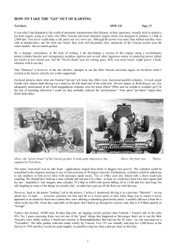


© Copyright 2026