
Business Process Integration: An Evaluation of How to Connect
Examensarbete
LITH-ITN-ED-EX--07/003--SE
Business Process Integration:
An Evaluation of How to Connect
Business Processes to the
Integration Layer
Fredrik Ekelund
2007-02-19
Department of Science and Technology
Linköpings Universitet
SE-601 74 Norrköping, Sweden
Institutionen för teknik och naturvetenskap
Linköpings Universitet
601 74 Norrköping
LITH-ITN-ED-EX--07/003--SE
Business Process Integration:
An Evaluation of How to Connect
Business Processes to the
Integration Layer
Examensarbete utfört i datavetenskap
vid Linköpings Tekniska Högskola, Campus
Norrköping
Fredrik Ekelund
Handledare Charles Halaas
Examinator Bengt Lennartsson
Norrköping 2007-02-19
Datum
Date
Avdelning, Institution
Division, Department
Institutionen för teknik och naturvetenskap
2007-02-19
Department of Science and Technology
Språk
Language
Rapporttyp
Report category
Svenska/Swedish
x Engelska/English
Examensarbete
B-uppsats
C-uppsats
x D-uppsats
ISBN
_____________________________________________________
ISRN LITH-ITN-ED-EX--07/003--SE
_________________________________________________________________
Serietitel och serienummer
ISSN
Title of series, numbering
___________________________________
_ ________________
_ ________________
URL för elektronisk version
Titel
Title
Författare
Author
Business Process Integration: An Evaluation of How to Connect Business Processes to the Integration
Layer
Fredrik Ekelund
Sammanfattning
Abstract
The purpose
of this master thesis work is to evaluate how Vetco Aibel shall enable business
process integration in their IT organisation as well as recommend how to continue their
integration work. The outcome of this work is a discussion of how Microsoft BizTalk Server
2006 can be used for business process integration in Vetco Aibel and a set of
recommendations for how Vecto Aibel shall continue their future integration work.
Nyckelord
Keyword
Business, process, integration
Upphovsrätt
Detta dokument hålls tillgängligt på Internet – eller dess framtida ersättare –
under en längre tid från publiceringsdatum under förutsättning att inga extraordinära omständigheter uppstår.
Tillgång till dokumentet innebär tillstånd för var och en att läsa, ladda ner,
skriva ut enstaka kopior för enskilt bruk och att använda det oförändrat för
ickekommersiell forskning och för undervisning. Överföring av upphovsrätten
vid en senare tidpunkt kan inte upphäva detta tillstånd. All annan användning av
dokumentet kräver upphovsmannens medgivande. För att garantera äktheten,
säkerheten och tillgängligheten finns det lösningar av teknisk och administrativ
art.
Upphovsmannens ideella rätt innefattar rätt att bli nämnd som upphovsman i
den omfattning som god sed kräver vid användning av dokumentet på ovan
beskrivna sätt samt skydd mot att dokumentet ändras eller presenteras i sådan
form eller i sådant sammanhang som är kränkande för upphovsmannens litterära
eller konstnärliga anseende eller egenart.
För ytterligare information om Linköping University Electronic Press se
förlagets hemsida http://www.ep.liu.se/
Copyright
The publishers will keep this document online on the Internet - or its possible
replacement - for a considerable time from the date of publication barring
exceptional circumstances.
The online availability of the document implies a permanent permission for
anyone to read, to download, to print out single copies for your own use and to
use it unchanged for any non-commercial research and educational purpose.
Subsequent transfers of copyright cannot revoke this permission. All other uses
of the document are conditional on the consent of the copyright owner. The
publisher has taken technical and administrative measures to assure authenticity,
security and accessibility.
According to intellectual property law the author has the right to be
mentioned when his/her work is accessed as described above and to be protected
against infringement.
For additional information about the Linköping University Electronic Press
and its procedures for publication and for assurance of document integrity,
please refer to its WWW home page: http://www.ep.liu.se/
© Fredrik Ekelund
Preface
This master thesis report is the outcome of 20 weeks work, carried out from July 2006 to
November 2006. This thesis was performed at Vetco Aibel in Oslo and will function as a
guide for future integration decisions.
I would like to thank Lars Line Vaaland in Vetco Aibel for giving me the opportunity to do
this master thesis work. I would also like to thank the staff in the IT department for their
valuable contribution when I needed information about the very complex organisation Vetco
Aibel. Even though they already have a heavy workload they have always answered my
questions.
I would also like to point a special thanks to my supervisor, Charles Halaas. Even though he
has been busy with his own work, he has always been there for me, guiding me along the way
and discussing ideas.
At last I would like to thank Bengt Lennartsson at Linköpings University for being my
examinator.
Oslo, January 2007
Fredrik Ekelund
II
Abstract
The fact that information becomes more and more vital in organisations today is well known.
Companies exchange large amount of data each day and therefore their administrating
functions must be dynamic and flexible. As the applications tend to be more complex and
increase in number as the company grows the requirements for integration of the different
applications becomes even more important.
The purpose of this master thesis work is to evaluate how Vetco Aibel shall enable business
process integration in their IT organisation as well as recommend how to continue their
integration work. The outcome of this work is a discussion of how Microsoft BizTalk Server
2006 can be used for business process integration in Vetco Aibel and a set of
recommendations for how Vecto Aibel shall continue their future integration work.
The work was initiated with a background study of integration concepts and technologies.
Then, interviews with different Vetco Aibel employees were done to get an overview of their
current IT solution. The proof of concept work was then initiated and finally a brief analysis
of Vetco Aibel’s SPF-project was done.
The master thesis work was carried out from July 2006 to November 2006.
III
IV
Table of Contents
1 INTRODUCTION.............................................................................................................................................. 1
1.1 BACKGROUND ............................................................................................................................................... 1
1.2 TASK ............................................................................................................................................................. 1
1.3 PURPOSE ....................................................................................................................................................... 1
1.4 METHOD........................................................................................................................................................ 2
1.5 DELIMITATIONS ............................................................................................................................................. 2
1.6 THESIS OUTLINE............................................................................................................................................ 2
2. COMPANY PRESENTATION ....................................................................................................................... 4
2.1 HISTORY........................................................................................................................................................ 4
2.2 LINE OF BUSINESS ......................................................................................................................................... 4
3 FRAME OF REFERENCE............................................................................................................................... 5
3.1 EAI – ENTERPRISE APPLICATION INTEGRATION............................................................................................ 5
3.1.1 Data Integration Process...................................................................................................................... 6
3.1.2 Architecture .......................................................................................................................................... 8
3.1.3 Orchestration...................................................................................................................................... 12
3.2 BPM – BUSINESS PROCESS MANAGEMENT ................................................................................................. 14
3.2.1 BPM Life Cycle................................................................................................................................... 14
3.3 SERVICE ORIENTED ARCHITECTURE (SOA) ................................................................................................ 18
3.5.1 What is SOA?...................................................................................................................................... 18
3.5.2 Why SOA?........................................................................................................................................... 19
3.5.3 Important standards ........................................................................................................................... 21
3.5.4 Reusable Services ............................................................................................................................... 23
3.5.5 SOA Middleware ................................................................................................................................ 24
3.5.6 Enterprise Service Bus (ESB) ............................................................................................................. 25
4. BUSINESS PROCESS INTEGRATION – A PROOF OF CONCEPT...................................................... 27
4.1 PURPOSE AND METHOD ............................................................................................................................... 27
4.2 THE MEASURE PROGRESS PROCESS ............................................................................................................ 28
4.3 MICROSOFT BIZTALK SERVER 2006 ........................................................................................................... 29
4.3.1 The BizTalk Server 2006 Engine ........................................................................................................ 29
4.3.2 Development Tools in BTS2006.......................................................................................................... 31
4.4 TEST PLATFORM .......................................................................................................................................... 36
4.4.1 Data Flows ......................................................................................................................................... 37
4.5 DISCUSSION................................................................................................................................................. 37
4.6 RESULTS...................................................................................................................................................... 40
5. RECOMMENDATIONS FOR FUTURE INTEGRATION WORK AT VETCO AIBEL....................... 41
5.1 SPF PROJECT ............................................................................................................................................... 41
5.1.1 SPF Project Scope .............................................................................................................................. 41
5.1.2 Architecture and Interfaces ................................................................................................................ 41
5.2 IMMEDIATE ACTIONS .................................................................................................................................. 42
5.2.1 Introduce a Solution Architect............................................................................................................ 43
5.2.2 Middleware Application Integration .................................................................................................. 44
5.2.3 Integration Center of Competency...................................................................................................... 44
5.3 INTRODUCE A SOA INITIATIVE ................................................................................................................... 47
5.4.1 Five steps of How to Initiate a SOA Pilot Project .............................................................................. 47
6. CONCLUSIONS & LESSONS LEARNED.................................................................................................. 49
REFERENCES.................................................................................................................................................... 50
V
Table of Figures
FIGURE 1: A DESCRIPTION OF THE DATA INTEGRATION PROCESS. ........................................................................... 6
FIGURE 2: NO DATA COMMUNICATION BETWEEN THE DEPARTMENTAL BOUNDARIES............................................. 8
FIGURE 3: PEER-TO-PEER ARCHITECTURE............................................................................................................... 9
FIGURE 4: ARCHITECTURE WITH A MIDDLEWARE APPLICATION WORKING AS A HUB. ........................................... 10
FIGURE 5: CONCEPTUAL DESCRIPTION OF A MESSAGE BROKER............................................................................ 11
FIGURE 6: CONCEPTUAL DESCRIPTION OF A PROCESS BROKER ............................................................................. 12
FIGURE 7: THE BPM LIFE CYCLE ......................................................................................................................... 15
FIGURE 8: FLEXIBILITY IS THE DRIVER .................................................................................................................. 20
FIGURE 9: A WEB SERVICES MODEL ..................................................................................................................... 22
FIGURE 10: A MODEL OF COMPONENTS INCLUDED IN A SOA. (SOURCE: GARTNER)............................................. 25
FIGURE 11: A GENERAL DESCRIPTION OF AN ESB ................................................................................................ 26
FIGURE 12: A BUSINESS PROCESS MAP DESCRIBING THE MEASURE PROGRESS PROCESS........................................ 29
FIGURE 13: THE BIZTALK SERVER 2006 ENGINE. (SOURCE: MICROSOFT.COM).................................................... 30
FIGURE 14: AN OVERVIEW OF THE FOUR MOST IMPORTANT DEVELOPMENT TOOLS IN BTS2006. ......................... 31
FIGURE 15: A SCREEN DUMP ILLUSTRATING THE BIZTALK EDITOR. ..................................................................... 32
FIGURE 16: A SCREEN DUMP ILLUSTRATING THE BIZTALK PIPELINE DESIGNER................................................... 33
FIGURE 17: A SCREEN DUMP ILLUSTRATING THE BIZTALK MAPPER..................................................................... 34
FIGURE 18: A SCREEN DUMP ILLUSTRATING THE BIZTALK ORCHESTRATION DESIGNER. ..................................... 35
FIGURE 19: THE TEST PLATFORM USED IN THE PROOF OF CONCEPT....................................................................... 36
FIGURE 20: AN OVERVIEW OF THE SPF-PROJECT’S APPLICATION ARCHITECTURE. ............................................... 42
FIGURE 21: ALL ROLES IN AN ICC. (SOURCE: GARTNER) ..................................................................................... 45
VI
1 Introduction
This chapter serves as an introduction to this master thesis work. Initially, a background to
the thesis will be presented followed by a discussion of the problem. Then, the purpose,
method and delimitations will be stated and finally the outline of the report will be presented.
1.1 Background
Companies exchange large amount of data each day and therefore their administrating
functions must be dynamic and flexible. As the applications tend to be more complex and
increase in number as the company grows the requirements for integration of the different
applications becomes even more important.
Vetco Aibel is a company that uses advanced engineering software tools, which are
strategically important for being successful in projects. Vetco Aibel’s IT department has been
looking for a way to connect these applications in a more flexible way and also make them
support Vetco Aibel’s business processes. By integrating these business processes into the
application integration solution, Vetco Aibel will be able to respond to market fluctuations
quicker and also reduce maintenance costs involved in the today’s IT solution. Therefore,
Vetco Aibel has invested in a new application integration tool, Microsoft BizTalk Server
2006, which will be a part of their new IT system.
1.2 Task
This master thesis project includes two tasks. The first task was to evaluate if Microsoft
BizTalk Server 2006 (BTS2006) can be used for business process integration in Vetco Aibel.
A proof of concept that involved business process selection, programming of BTS2006, and
deployment of the server was carried out in this part. The second task was to give Vetco Aibel
recommendations on how to continue the future integration work. This work involved a brief
analysis of Vetco Aibel’s SPF-project to address problems in the today’s integration work as
well as an evaluation of how Vetco Aibel shall drive their long-term integration work.
1.3 Purpose
This thesis aims to evaluate how Vetco Aibel shall enable business process integration in their
IT organisation as well as recommend how to continue their integration work. The business
process integration evaluation shall indicate if BTS2006 can be used to integrate business
processes in Vetco Aibel. The recommendations for how Vetco Aibel shall continue their
integration work shall be related to Vetco Aibel’s current situation.
1
1.4 Method
The theoretical foundation of the required knowledge was obtained by reading academic
articles, white papers, relevant chapters in books and useful interviews with managers,
consultants and specialists working at Vetco Aibel. Courses and seminars were also important
sources of information.
The analysis of how to enable business process integration in Vetco Aibel was based upon
theoretical studies in application integration and a brief analysis of Vetco Aibel’s current ITsolution. The performed analysis of Microsoft BizTalk Server 2006 was initiated after the
author of this report took part in a one week introduction course. The test platform was
installed on a local PC and the work was done on a trial and error basis.
One of the main sources of information was Gartner, an IT-analyst organisation, which main
line of business is IT research. Gartner is serving over 10,000 customers with research reports,
seminars and personal IT advisory to help organisations develop their IT organisation to be
more flexible and effective. The main reason for using Gartner as the main source of
information in this report was that Vetco Aibel was interested in recommendations based on
the latest integration trends.
1.5 Delimitations
This thesis treats both a proof-of-concept of BTS2006, and an analysis of how Vetco Aibel
shall continue their future integration work. Therefore, the detail level of the results must be
conceptual and cannot describe technological issues, such as system performance, and
financial issues. The proof-of-concept cannot be performed on a full-scale test platform and
simulated data will therefore be used.
Vetco Aibel has a large number of strategic applications and since this is the result of a thesis
performed in 20 weeks it is not enough for taking every application in consideration for best
integration practice. Only the applications involved in the process chosen for the proof of
concept will be described in this report.
1.6 Thesis Outline
The two first chapters of this thesis, Introduction and Company Presentation, give the reader a
brief introduction of Vetco Aibel, the problem background and the purpose of this thesis.
2
These two chapters are recommended if the reader does not already know Vetco Aibel as an
organisation.
The third chapter, Frame of Reference, is describing the main concepts in business process
and application integration. The Enterprise Architecture Integration section is recommended
for readers who have no previous knowledge in application integration, while the sections
Business Process Management and Service Oriented Architectures are recommended for
readers who are interested in concepts for how to connect business processes to the
application layer.
The fourth chapter, Business Process Integration – A Proof of Concept, is the outcome of the
first task in this master thesis work, namely if BTS2006 can be used for business process
integration in Vetco Aibel.
The fifth chapter, Recommendations for Future Recommendation Work at Vetco Aibel, is the
outcome of the second task in this master thesis work. This chapter contains a brief
description of Vetco Aibel’s ongoing SPF-project to give the reader the necessary information
needed for understanding the future recommendations.
The following chapter, Results and Conclusions, will give the reader a collection of results
and conclusions from both tasks in this master thesis work. Finally, the references for this
master thesis work are presented in the last chapter, References.
3
2. Company Presentation
This chapter will give a brief presentation of Vetco Aibel and its main line of business. The
presentation is based on information from Vetco Aibel’s intranet and interviews with the
manager of engineering applications, Charles Halaas.
2.1 History
Vetco Aibel traces its roots to Elektrisk Bureau (EB) and Norsk Elektrisk Brown Boveri
(NEBB); two companies that were founded in Norway a century ago. A separate offshore
business, EB Offshore, was founded in 1989. Through acquisitions of Seatec, Maritime
Seanor and Umoe Oil and Gas as well as organic growth, ABB Offshore Systems evolved. In
connection with the divestment of the Upstream Oil and Gas division from ABB in July 2004,
the company changed its name to Vetco Aibel.
2.2 Line of Business
Vetco Aibel is a leading provider of upstream oil and gas production facilities, process
systems, technology and products. From new build to decommission, they also maintain,
modify and operate on- and offshore facilities. With over 100 years of industry experience
and over 6,000 professionals on all continents Vetco Aibel are dedicated to meeting the
customers’ needs.
Vetco Aibel has several decades of experience in serving the oil and gas industry. Their
portfolio of products and services includes engineering, procurement, project management,
construction, and installation services in addition to the supply of process products.
4
3 Frame of Reference
The theoretical foundation of the thesis is presented in this chapter. Initially, an introduction
to Enterprise Application Integration (EAI) will be given. Some background information,
fundamental integration techniques as well as an update of what EAI is about today will be
presented in the EAI section. Then, a brief description of the concept, Business Process
Management will be given. This section is recommended for readers who have no background
knowledge about business processes. Finally, the basics of Service Oriented Architecture will
be introduced. It is assumed that the reader has a basic knowledge in Information Technology
and an understanding of basic business terms.
3.1 EAI – Enterprise Application Integration
Today, organisations must operate efficiently and be flexible to be able to respond to
changing market conditions. To meet this first challenge, IT departments must continually
seek ways to support new improved business processes that will increase the effectiveness of
the organisation. The second challenge is to make IT systems extendable so that the
organisation easily can apply changes in the IT system as the demand changes. Enterprise
Application Integration is one of the key technologies to meet this mandate.
The demand for EAI is driven by enabling technologies such as Internet and enterprise
software packages. Internet provides an environment that makes it possible for companies to
connect their business with customers, suppliers or partners, which has today become an
important factor for being competitive. Enterprise software packages are offering enterprises
an integrated platform for supporting business processes across the functional departments in
an organisation. Traditionally, there are mainly two categories of enterprise software
packages, front-office and back-office supporting systems. ERP (Enterprise Resource
Planning) systems are typically managing back-office requirements, while other packages
support front-office capabilities such as sales and marketing. One of many advantages with
application integration is to connect front-office systems with back-office systems to achieve
an organisation where the information flows not only within the different departments but also
across the departmental boundaries. This means that an organisation’s different applications
that historically have been operating independently of each other, can be connected and
exchange information to enable a more dynamic and flexible IT-solution. (Johannesson et al.,
2000)
Today, the scope of application integration has been extended as new technologies and tools
have entered the market. This technologically development has made it possible for
organisations to develop highly flexible IT-solutions that fully support today’s businesses.
5
The following sections will describe the basics of EAI and the enabling technologies available
today.
3.1.1 Data Integration Process
Many processes for integrating data and connect disparate systems have been developed since
integration became an important business driver in the beginning of the 90s. However, when
looking closer at the different conceptual theories and approaches, there are basically four
steps that are common and that describe the process of data integration well. These four steps
are:
1.
2.
3.
4.
Extraction
Transportation
Transformation
Insertion
Figure 1: A description of the data integration process.
First, the extraction process aims to produce data in a proper format, usually a text file or an
xml document, so that it can be packaged for transportation and finally received by the correct
recipient. This step is often the easiest problem to tackle, as most applications have a way of
producing data for export, either manually or automatically. For applications that cannot
extract data because they are old propriety systems (legacy systems), techniques such as
screen scraping are available. (Gleghorn, 2005)
The next step is transportation, which is about how to transfer the extracted data to the correct
recipient. Data can of course be transported in many ways and according to Gleghorn (2005)
the four requirements below should be considered in the transportation step.
•
Security. A sufficient amount of security must be applied when transmitting data. This
is important for making the information unusable if it gets stolen or in other ways
misused.
6
•
•
•
Reliable communications. The system must be able to identify the correct receiver and
also confirm that the sent information has reached its recipient and the transmission’s
success.
Completeness. The transportation process must ensure that all packets were received
and reassembled correctly.
Logging and Archiving. The system should archive and log documents and results to
prevent data loss. This information can also be used for discovering bottlenecks in the
system.
Like extraction, transportation is normally easier to implement than the transformation and
insertion operations. There are a number of reasons for this. First, most applications can
handle base communication techniques. Development frameworks, such as J2EE and
Microsoft .NET provide access to communications functionality without needing low-level
programming. In addition, industry standards have made it easier for developers to use, for
example, standard security protocols and other packages ready for implementation.
After transportation, the data needs to be transformed. The transformation step is about
formatting the source data so that it fits the target data structure. Most of the systems today
use the open standard, Extensible Style Sheet Language Transformation (XSLT), which will
be further described in section 3.5.3, to transform data. Normally the process of
transformation consists of 2 steps:
•
•
Mapping. In the design phase, the developer makes maps that describe the relationship
between incoming data fields and the data fields in the target application. The map
usually contains instructions for data-type conversions and identifies mandatory fields.
Transformation. At run time, the transformation process uses a map to convert the
incoming data to the outgoing data structure.
Once the data has the correct format, it can be imported into the target application. The
insertion process normally has three components:
•
•
Validation. A process validates the new data against the target application’s business
rules. This step is often performed by a middleware component, such as a rules engine.
Workflow. This component handles the routing of messages so that each message will
reach all of its recipients. It is also in this step that mandatory fields are checked, for
example, if a mandatory data field is missing at the target application the message can
be sent back to the source application and request for the missing data.
7
•
Insertion. If data are valid, the integration system must understand enough about the
target application to be able to insert the data. This often requires customized adapters
but in commercial brokers etc. adapter for the most common formats are available. It
is common to wrap legacy applications so that information can be exposed in a
convenient format.
The four steps of data integration describe the logical operations in an integration solution. It
is important to understand that these steps can be packaged different depending on the choice
of architecture, which will be discussed in the next section.
3.1.2 Architecture
Historically, organisations have been divided into different departments such as, sales,
procurement, marketing et cetera. The main weakness of this kind of organisational structure
is that it requires a large administration apparatus to handle problems that occur when
crossing between the departmental boundaries.
Traditionally, applications have been built to support one specific department. In other words,
each department has a good support from its application but the communication between the
different applications is poor or non-existing. (Johannesson et al., 2000)
Figure 2: No data communication between the departmental boundaries.
8
When connecting applications many different kinds of architectures can be supported.
Historically, the peer-to-peer solution has been the most common one. This architecture
requires each application to be connected to every other application. This approach is working
for a small number of applications, but when the number of applications increases, the
number of connections increases rapidly and the solution will soon be far to complex. The
peer-to-peer solution is also called “spaghetti architecture”. (Gleghorn, 2005)
App. 1
App. 8
App. 2
App. 7
App. 3
App. 4
App. 6
App. 5
Figure 3: Peer-to-peer architecture.
For instance, if a company has three applications that will be connected using a peer-to-peer
architecture, the number of connections will be n(n-1) where n is the number of applications.
In this case the company will need twelve connections. If a company instead has ten
applications, the number of connections will be 90. This proves the fact that the usage of a
peer-to-peer architecture is limited and dependent of the number of applications in the
organisation.
9
Another disadvantage with the peer-to-peer architecture is that each application needs one
interface per connection that transforms data to the right format. As each interface is uniquely
designed to transform data between two specific applications no programming code can be
reused, which will lead to excessive development and maintenance costs.
By introducing an inter-application middleware, the number of connections is reduced
remarkably as each application is only connected to the middleware application. As figure 4
shows, the inter-application middleware functions as a hub in the integration network. The
main advantage with this kind of architecture is that if one of the applications changes
document format or is to be replaced; only the interface to the middleware must be
reconfigured. This makes it possible for organisations to extend and reconfigure their ITsolutions with higher flexibility and lower costs; the system can be referred to as scalable.
(Hasselbring, 2000; Lee et al., 2003)
App. 1
App. 8
App. 2
Middleware
App. 7
App. 3
App. 4
App. 6
App. 5
Figure 4: Architecture with a middleware application working as a hub.
10
Traditionally, most of the middleware applications are of either a message broker type or a
process broker type. The message broker works as a message router, to which all applications
are connected, and it is simply routing messages from a transmitting application to a receiving
application. Mapping and transformation of data is also handled within the frames of the
message broker. Today’s message brokers are handling all four steps explained in section
3.1.1. The extraction process is often performed with different kinds of adapters that support
various data types. Normally, a set of adapters follows with the broker and then 3rd party
products can be installed to support other data types. The transportation methods are different
depending on which broker product that is used. However, most of the products support
different types of security protocols, they support data and delivery validation, and they all
use XML (eXtensible Markup Language) as the internal information language. (Hasselbring,
2000; Lee et al., 2003)
App. 1
App. 2
App. 3
Message Broker
App. 4
App. 5
App. 6
Figure 5: Conceptual description of a Message broker.
11
The process broker is an extension of the message broker that in addition to the message
broker also encapsulates the process logic for connecting applications. When all process logic
resides in one place, it becomes possible to study, analyse, and change the processes using a
graphical interface.
Figure 6: Conceptual description of a Process broker
3.1.3 Orchestration
Orchestrations are an important part of EAI solutions today as these contain the business
logic. A graphical programming interface is most common in today’s process brokers when
adding business logic in the EAI product. One of the main reasons why it is important to have
a graphical interface for programming orchestrations is because it is easier for people who are
not developers to understand how the data flows in the orchestrations. Another reason is that
the developers shall be able to implement processes directly from a business process map
designed in, for instance, Microsoft Visio.
The process logic can be implemented in mainly two different ways. First, the most common
way of implementing process logic in an organisations integration system is to use the
broker’s internal orchestration developer. These often have an extended number of functions
but that are only working in that specific broker product. The other way of implementing
12
process logic is to use the standardised process language BPEL (Business Process Execution
Language) which was authored by IBM, Microsoft along with BEA Systems, SAP and Siebel
Systems. The main advantage with BPEL is that it does not matter which broker product that
is used. This gives the organisation a more flexible environment as it can change broker or
share processes with customers and suppliers. The main disadvantage with BPEL is the lack a
graphical programming interface and its limited functionality. (McCoy & Smith, 2003)
13
3.2 BPM – Business Process Management
This section gives an introduction of Business Process Management as this is one of the
important concepts used in integration work today. However, discovery, design, development,
and deployment of business processes in Vetco Aibel is out of scope for this master thesis
work.
The last decade many organisations have realised the importance of describing, automating,
and managing their business processes. This interest mainly grows out of the wish to
streamline operations, save costs, and add business flexibility to faster respond to market
fluctuations.
The design, development and automation of business processes have its own field of study,
called BPM (business process management). IBM sums up what BPM is really about:
“BPM technology provides not only the tools and infrastructure to define, simulate,
and analyze business process models, but also the tools to implement business
processes in such a way that the execution of the resulting software artifacts can be
managed from a business process perspective.”
3.2.1 BPM Life Cycle
Today BPM technology is promising and many vendors are delivering large-scale solutions
with tools that fully support the complete BPM life cycle. Although IT analysts and
professionals agree on the fact that BPM has the potential to deliver significant value to
businesses, they do not believe that the BPM technology is mature enough.
Innovations in technology such as XML, Web services, component-based development, and
message-oriented middleware have gained interest in BPM. Today’s Business Process
Management Systems provide the fine-grained integration of systems and data needed to
automate the organisations’ business processes. The BPMS encapsulates everything that was
previously a set of many different products from different vendors in one integrated system.
This system links people and systems, manages information access and transformation,
handles exceptions, and orchestrates the flow of the process. (Sinur, 2006)
According to Laury Verner the main focus is on four challenges facing BPMS, which are
related to the four phases of the application development life cycle:
14
1. Discovery is about having an understanding of the current business environment and
business processes. This phase includes the mapping of current business processes and
to create a knowledge foundation for how the business’ end-to-end processes are
executed.
2. The design phase aims to analyse the current processes and to define the future state
processes.
3. The main focus in the development phase is to implement the new processes in
technology, which often includes process automation using BPMS (business process
management system).
4. The deployment phase is simply the phase where all processes will be put in
production.
The Process Life Cycle
Discovery
Design
Deployment
Development
Figure 7: The BPM Life Cycle
To be able to improve business processes it is important to know the existing ones. Most large
organizations have a fairly good understanding of their business processes. However, they
simply do not know their end-to-end processes accurately or detailed enough. Their process
knowledge is often decentralized and tacit instead of centralized and explicit. This means that
the knowledge about the processes must be discovered and mapped. According to Verner
(2004) there are mainly two different methodologies for mapping processes in a business, the
top-down or the bottom-up approach.
15
The top-down approach often starts with the organisation chart, where all responsibilities of
each department are listed and where all top-level processes that support these responsibilities
are identified. These processes will then be divided into sub-processes that describe the lower
levels of the processes. The advantage of this approach is that it gives a broad, organisational
perspective. However, the level of detail and the degree of accuracy can be questioned.
The bottom-up approach often begins with interviewing employees about their common day
work. These low-level processes are then integrated to trying to find the end-to-end processes.
This approach can be very accurate and precise but there is also a major risk to get lost in the
details. Many businesses try to use a hybrid of the two approaches to get the advantages from
both approaches.
The second challenge is the design phase, which comprises to identify the business processes
in a way that makes it possible for both business people and developers to understand how to
continue the design and execution phase. It is often business analysts who visually try to
represent the business processes in the organisation while the developers later on will try to
automate the new processes in a BPMS. It is therefore important to always have both a
business and a development perspective when analysing and improving the processes.
One major problem that BPMS vendors are working with is the lack of a universal process
description language that business analysts can use to design and model processes in a way so
that developers would understand how to develop centralized reusable processes that could be
invoked by processes in different operating units. Such a language would help to build a
bridge between business people and technology-oriented developers. BPEL is the only
programming language today that can reside business logic in a standardised way. However,
BPEL, in its current form, cannot be used by business people and it has no graphical
rendering which makes it less appropriate as a business process modelling language.
The third challenge is how to handle the development. A successful development project is
the result of many different conditions, where one of the most important being close
collaboration between business analysts, who knows what the business needs, and developers,
who implement technological solutions that meet these needs. Business analysts and technical
developers, however, speak different languages and are driven by different goals, and are
normally working at different levels of precision. In the domain of BPM this gap is specified
by a mismatch between the automated business processes and the original business
requirements.
16
The fourth and last challenge is the execution phase, which is simply the same as rolling out
for production. In this phase the most important task is to monitor data to see if the designed
processes are meeting the intended goals. This can be done with specific monitoring tools,
which are often called BAM (Business Activity Monitoring) in the BPM products. This is a
term coined by Gartner and is today a standard feature in most BPMSs. A BAM tool can be
used to monitor and aggregate data in real-time and present it at a business-process level. It is
in the interest for every manager to determine if the processes they are responsible for are
meeting their objectives.
17
3.3 Service Oriented Architecture (SOA)
SOA (Service Oriented Architecture) is probably the last step in an evolution that has moved
towards a world where applications share the same resources and information.
First, terms like Distributed Computing Environment (DCE) and Remote Procedure Call
(RPC) entered the IT-world. These made it possible for an application on a client to
communicate with another application on a server. This trend continued and in the middle of
1990s programming was done in an object-oriented way instead of the conventional
sequential way. This was path-breaking because of the fact that object-oriented programming
made it possible to reuse code in several applications. To make it possible for these objectoriented applications to communicate with each other, DCom and Corba were launched.
Unfortunately, none of the two concepts were successful. In the end of 1990 and the
beginning of 2000 web services were introduced as the new path-breaking technology, which
would make it possible for applications to communicate with each other without implicit
reprogramming of the applications. Incredibly, Microsoft, Sun, Oracle, and IBM agreed on
that common standards were necessary to continue the work towards web services.
This standardisation laid the foundation for making it possible to implement a service oriented
architecture. (Seks steg till serviceorientert arkitektur, 2006)
SOA is one of the most discussed trends in the IT world today. Almost every IT manager
considers implementing SOA or at least investigating it closer. According to IDG Research
Services, more than half of all American organisations mean that SOA is one of the areas with
highest priority this year. Over 80 percent says that SOA will have the highest priority during
the next five years. (Gartner Research)
3.5.1 What is SOA?
“A service-oriented architecture is a collection of services that communicate with
each other. The services are self-contained and do not depend on the context or state
of the other service. They work within a distributed systems architecture.”
DMreview.com
It is a common misunderstanding that SOA is a tool or product that will help organisations to
handle their integration problems. SOA is in its broadest interpretation used as a synonym for
distributed computing, which in practice will mean that a system with two modules, which
run on different computers and send data to each other, is SOA. Some people would call all of
the modules in a system, even the clients, “services”. (Bieberstein et al., 2005)
18
Others mean that SOA is when any application uses one or more of the web services
standards, for instance, SOAP, XML, WSDL etc.
The third, and probably most accurate, interpretation of SOA is to define SOA in a way that
reflects good practices in distributed application design. This SOA definition is “the
relationship between clients and services”, where “service” is referred to as a software module
with certain properties. There are of course a variety of properties, which lead to a variety of
definitions for SOA. An example of a service definition can be a module that:
(Bieberstein et al., 2005)
•
•
•
Can be reused in different applications because it can be invoked by different clients
Performs exactly one task and has one defined set of inputs and outputs.
Has implementation metadata so that the service module can be dynamically identified
and located at run-time. Modules can be swapped with a new module at any time
without affecting any client as long as the interface is not changed.
3.5.2 Why SOA?
“Service-oriented architecture will be used in more than 67% of new, mission-critical
operational applications and business processes designed in 2007, and in more than
90% by 2010 (0.8 probability).” Gartner Research
Many organisations are today considering SOA as the next large-scale IT-project. Even if
SOA is the trend today and every expert and analyst says it is a promising approach, every IT
manager asks themselves why SOA, and is it the proper solution for their organisation.
The driver for SOA can be different from organisation to organisation. For some, the need for
a more modern and dynamic IT-infrastructure can be the driver. Others apply SOA because
their partners require a standardised access to information. The common denominator for the
different approaches to SOA is that a renewal of the organisations’ processes is necessary to
cope with the extremely dynamic markets of today. (Seks steg till serviceorientert arkitektur,
2006)
19
Flexibility is the driver
90 %
80 %
70 %
60 %
50 %
40 %
30 %
20 %
10 %
0%
77 %
61 %
Increased
Flexibility
Lower total
costs
49 %
47 %
Lower
software
costs
Shorter
development
time
Figure 8: Flexibility is the driver (Source: Gartner Research)
It is also a fact that many of the large software vendors are SOA-enabling their products, for
example Oracle’s Fusion Applications and SAP’s Enterprise SOA. This makes it even more
important for enterprises to adopt a Service Oriented Architecture.
Some IT-analysts believe that SOA definitely is the future while some believe that it will
break. Whatever it will be, Gartner means there are a lot of advantages with SOA and some of
them will be described below:
•
•
•
•
Standardised communication. Once an application is prepared for SOA, it can easily
be connected with other SOA applications or services almost without customization.
Scalability. The IT systems can easily be extended without reprogramming of
applications or interfaces.
Loose coupled applications. Applications will connect via internet or the
organisation’s intranet. The IP-address to and a description of the application’s
services will be described in a service catalogue, for instance, UDDI (Universal
Description, Discovery and Integration). This means that if an application or a service
is moved or removed only the service catalogue must be updated.
Service oriented. Instead of applications that support each organisational department,
services that support the business processes can be accessed and aggregated to
perform exactly the task that is needed for the moment. This makes it easier to update
and maintain the IT-systems so that they always support the business’ actual processes
instead of letting the processes adapt to the IT-systems.
20
•
•
B2B integration. While standards are used to apply SOA it becomes convenient to
connect processes to partners, customers or/and suppliers that also have applied SOA.
Platform independent. As soon as an application has been wrapped for SOA it
becomes platform independent because the use of open standards.
As mentioned before, many of the leading software vendors are SOA enabling their products.
Gartner means that this will lead to that many organisations will have to take the necessary
steps towards SOA to adapt to these leading vendor’s products. SOA will therefore be
considered mainstream in 2010. (Gartner Briefing)
3.5.3 Important standards
Even though standards like XML, WSDL and SOAP alone do not define SOA, they play a
significant role when developing program modules that can be localised and executed from
any location, both inside the organisation or via the internet. Leading software vendors has
worked together to develop these standards that together is the foundation for the term web
services that will be discussed below. The standardisation work is carried out by mainly four
large independent organisations, OASIS (Organization for the Advancement of Structured
Information Standards), W3C (World Wide Web Consortium), WS-I (Web Services
Interoperability Organization) and Liberty Alliance. The most important standards for SOA
on the market today are: (www.w3.org)
•
•
•
•
•
Web Services
SOAP
XML
WSDL
BPEL
Web Services are today the most promising standard for applying a Service Oriented
Architecture to an organisation’s IT solution. The W3C definition of a web service is:
“A Web service is a software system designed to support interoperable machine-tomachine interaction over a network. It has an interface described in a machineprocessable format (specifically WSDL). Other systems interact with the Web service
in a manner prescribed by its description using SOAP-messages, typically conveyed
using HTTP with an XML serialization in conjunction with other Web-related
standards.”
21
A web service uses XML, WSDL, SOAP and UDDI to establish location and platform
independent data transactions using both the organisation’s intranet and the internet. Web
services should be used for system-to-system inter- or intra-connectivity where loosecoupling and standardised interchange formats are needed. Web services are not well suited
for internal application communication or function calls. The different open standards that
enable web services will be described below. (Gudivada & Nandigam, 2005)
Figure 9: A Web services model
SOAP (Simple Object Access Protocol) is an information exchange protocol suited for
distributed environments. SOAP describes how an xml-document is packaged and how the
document is formatted. This makes it possible to send xml-data over internet using standard
protocols as, for instance, TCP/IP. SOAP was originally developed by Microsoft and IBM but
was handed over to W3C to make it an open standard.
XML (eXtensible Markup Language) is a meta-language for storage and exchange of
structured data. The structure looks similar to html that is used for describing web pages.
XML is mainly used for exchanging information and is extensible in contradiction to html.
UDDI (Universal Description, Discovery and Integration) is a catalogue service where
information about every service is stored. This information contains location and description
of the requested service so when a client wishes to use a service, it contacts the UDDI
catalogue to receive the necessary attributes.
WSDL (Web Services Description Language) is used for writing xml-based web services and
to describe them. If a client or a web services try to contact another web service, a WSDLmessage, which describes the web service, will be the first response.
22
BPEL is a language, originally authored by IBM, Microsoft (along with BEA Systems, SAP
& Siebel Systems), used for automating business processes by orchestrating messages. BPEL
is XML-based and supports functions like error handling, transaction handling, mapping et
cetera. BPEL gathers business processes so that they together form a loosely coupled
application. The strength of BPEL is that it has become a standard orchestration language
because of its support from leading software vendors and that it is royalty free. However, even
though BPEL’s system-to-system functionality is good, the human-to-system and human-tohuman functionality is poor or non-existing.
3.5.4 Reusable Services
When implementing SOA it is important to identify services that can be reused. This is crucial
for a successful SOA because the reusable services are the cornerstone of adding value to the
business. If a business can identify and implement their reusable services in a way that they
can be used as small “applications” across the departmental boundaries, the SOA
implementation will be successful. (Bieberstein, 2005)
Businesses can save a huge amount of time and money in terms of maintenance costs on
identifying reusable services. However, it is common that organisations end up with
thousands of services where most of them are duplicates with small modifications. It is
therefore important to have a methodology and strategy when identifying the services.
According to Massimo Pezzini, there are three major approaches to identify which services
that are needed:
•
•
•
Process-Centric (Top-Down). Starting from a formal definition of the application
domains at the enterprise architecture level, business analysts model key business
processes. Expensive but accurate. Similar to the top-down approach described in
section 3.2.1
Data-Centric (Bottom-Up). Services are created through the aggregation of basic
create, read, update and delete components manipulating the entities of a given data
model. Similar to the bottom-up approach described in section 3.2.1.
Application-Centric (Meet-in-the-middle). A combination of the Process-Centric and
the Data-Centric approaches. Most appropriate for most mainstream organisations.
Sharable (or reusable) services yield faster integration of applications, lower development
costs and easier maintenance of applications. However, sharing services is not simple; it
requires governance, incentives, discipline, and tools. The formal process for defining
23
services (described above) should involve business analysts, architects, developers and
integration specialists. The goal of this process is to make sure that each service is as broad as
possible in its set of requirement. This process is very costly and lengthy, so only services that
are ought to be reused across multiple domains should be submitted. Also, to avoid that
developers, which are normally under time pressure, are being rewarded for implementing a
large number of services in short time, Massimo Pezzini means that they should be rewarded
for delivering long-term reusable services. He also means that even in well-managed SOA
initiatives; only 30 percent to 40 percent of the implemented services are used by more than
one application, which proves the fact that most of the organisations that try to implement
SOA have problems with defining services that are reusable.
3.5.5 SOA Middleware
Gartner describes SOA Middleware as the “SOA backplane” in a Service Oriented
Architecture. Even though SOA is said to be enabled through open standards alone, the
solution will soon be far to complex if only SOAP and BPEL are to be used. The performance
will not be satisfying if these standards alone are the “backplane” of an enterprise’s
architecture. Therefore, products that make it easier to implement web services and connect
different applications to each other have entered the market. These products consist of many
different components like application servers, portals, integration suites, BPM tools,
integration servers and communication middleware. According to Gartner, to make the proper
product choices, users must understand the complex world of middleware and although the
growing interest of this technology, the risk of making the wrong choices is large for SOA
newcomers. [Gartner Briefing]
The SOA backplane is, as mentioned before, the most crucial SOA infrastructure component.
Support for web services protocols are supported of almost every “out of the box” software
platform and packaged application, but this is in most cases not enough to get a seamless,
open interoperability between consumers and service implementations. Very often, the SOA
backplane must support more than the SOAP protocol to meet the requirements of scalability
and performance. Proper integration products must be used to connect into legacy, non-Webservices-enabled applications. Dynamic discovery of services and mediation or transformation
of service invocations are often needed for flexible deployments in a distributed environment.
Service registry, tools to design and implement service interfaces and associated client proxies
are also examples of required features in the implementation of a SOA backplane. Most of the
needed features can be found in integration suites or ESBs (Enterprise Service Bus).
24
Figure 10: A model of components included in a SOA. (Source: Gartner)
3.5.6 Enterprise Service Bus (ESB)
This section will only give a very brief introduction to the ESB concept. The term is
mentioned in this report only to make the reader aware of an important component used for
realising SOA. However, ESBs will not be further discussed in this report as Vetco Aibel has
chosen a different technology for their integration solution, namely BTS2006.
An enterprise service bus is often used as another term for the conventional EAI brokers.
However, the concept and idea behind an ESB is different compared to the EAI-brokers. IBM
sums up the ESB concept nicely:
“The ESB is actually an architectural construct that can be designed and deployed in
a manner that will parallel the business processes environment. The bus can be
implemented in various ways, such as with classical messaging, EAI, and brokering
technologies or by using platform-specific components such as the service integration
buses in J2EE systems…” SOA Compass IBM p. 44
25
The ESB is implemented as an intelligent, distributed, transactional, messaging layer that is
used for connecting applications and services in an enterprise computing infrastructure.
Inbound
Access
points
A
B
C
Mediation, SDO
Routing, QoS
Mediation, SDO
Routing, QoS
Mediation, SDO
Routing, QoS
Transport, Routing, Security
ESB
Metadata
Outbound
Access
points
Mediation, SDO
Events
Mediation, SDO
Events
Mediation, SDO
Events
D
E
F
Figure 11: A general description of an ESB
26
4. Business Process Integration – A Proof of Concept
In this chapter I, the author, present the results of the practical work, regarding business
process integration, done at Vetco Aibel. First, the purpose of the work and how it was
carried out will be presented. Next, the chosen business process will be described, to then be
followed by information about the different applications involved in the proof of concept. At
last, a discussion of the results together with recommendations for further work will be
presented.
4.1 Purpose and Method
Most large organisations are today trying to find more dynamic and flexible IT-solutions. The
driver is often high maintenance costs and these can be decreased by introducing flexibility in
the IT-solution. This often implies large investments, complex data structures, and advanced
application integration tools. When trying to implement complex technology with advanced
tools it is important to knowing not only the advantages but also the limitations of the tools.
This part of the master thesis work was initiated to analyse and determine the possibilities of
connecting business processes to the application layer using Microsoft’s business process
management server, Microsoft BizTalk Server 2006. Three main aspects shall be evaluated
during this proof of concept. These are:
•
•
•
The possibility to automate an existing Vetco Aibel business process by using
BTS2006.
The possibility to transfer implicit interface logic from an external application into
BTS2006, making the interface logic visible.
Evaluate if BTS2006 is simple enough to be configured by someone without
developer skills to enable business users to change the automated processes.
Before the practical work was initiated a requirement specification was determined by the
author of this report and Charles Halaas, Manager Engineering Applications in Vetco Aibel.
The outcome of the requirement specification discussion was as follows:
•
•
•
•
•
Microsoft BizTalk shall be used as the middleware application.
An existing Vetco Aibel business process that involves at least two of Vetco Aibel’s
strategic applications shall be chosen as the process to be integrated.
The business process shall not be complex.
System performance is out of scope.
Data from applications connected to BizTalk will be simulated to prevent a time
consuming development of a test platform.
27
4.2 The Measure Progress Process
The process that was chosen for the proof of concept is considered non-complex, which was
one of the requirements for this practical part of the thesis. A non-complex process makes it
easier to measure the actual performance and flexibility in BTS2006. The risk with choosing a
complex process is that main focus can be transferred from BTS2006 onto the process itself.
Measure Progress is, as the name suggests, a process that describes how the business
measures the progress throughout a project. This is done according to a method, called
ProVision, which was developed by ABB. The method provides a framework for
management, organisation, and execution of complex projects as well as a methodology for
design development, interface management, and design coordination. ProVision will not be
further explained in this master thesis work as the details of this method are not relevant for
the further discussions and conclusions.
There was no official process map for the chosen process at the time when this work was
carried out. Therefore, the process had to be mapped by me, the author, to have a documented
process description as an initial starting point for this proof-of-concept. The outcome of the
business process mapping is shown in figure 12. The mapping method used for discovering
this process was based on instructions from business consultants working in Vetco Aibel.
However, the process map is only to be used as a reference for this proof-of-concept. A brief
explanation of the data flow in the process will be given in section 4.4.1.
Level 3 – Plan Project
Level 4 – Follow-up and Report Project Status
No
Plan
Project
Project
Baseline
COs from
PDMS
COs in EIS
Area Status
(PDMS)
Project Planning Team
Daily
Project
Baseline
Received
Import Plan
Activities
Manual
SafranManual
-> EIS
Safran -> EIS
Verify CO
Status Levels
Manual
EIS
Manual
EIS
Generate
Project
Activities
Automatic
EIS
Automatic
EIS
Connect COs
to Project
Activities
Manual
EIS
Manual
EIS
Monthly
Project Status
Report
System &
Purchase
Status (EIS)
Daily
Update &
Aggregate
Status
End of week?
Automatic
EIS
Automatic
EIS
Compare Weekly
Progress with
Project Baseline
Manual
EIS -> Safran
No
Import
Project
Activities
Manual
EIS ->Manual
Safran
EIS -> Safran
End of
month?
Yes
Compare Monthly
Progress with
Project Baseline
Manual
EIS -> Safran
Weekly
Project Status
Report
28
Plan
Project
Measure
Progress
Completed
Figure 12: A business process map describing the measure progress process.
There are three strategic applications used for keeping track of project progress.
These are:
•
•
•
EIS. Engineering Register that contains all engineering data in Vetco Aibel
Safran. Plan management tool that is used for planning and progress measuring of
projects
PDMS. 3D-Cad tool that is used for modelling every part in a construction project.
4.3 Microsoft BizTalk Server 2006
In present time, Vetco Aibel is working with the introduction of a new application
architecture to enable their strategic applications to communicate in a more flexible way. The
idea is to move from today’s peer-to-peer architecture, with all business process logic
embedded implicitly in each application, to a more flexible solution where all business
process logic resides in a process broker. This will decrease the response time when making
changes in the business processes and it will also enable the business greater control,
maintenance and monitoring of its IT system. Vetco Aibel has chosen Microsoft’s BizTalk
Server 2006 as the process broker to be used in their new IT solution.
On Microsoft’s webpage a brief explanation of MS BizTalk Server 2006 is given:
“BizTalk is a business process management (BPM) server that enables companies to
automate and optimize business processes.”
4.3.1 The BizTalk Server 2006 Engine
BTS2006 is an integration suite that contains tools for designing, developing, deploying, and
monitoring business processes. This application package is using standard technologies for
processing information and it is also delivered with a number of data adapters that is used for
connecting applications to BTS2006. SOAP-, FTP-, HTTP-, FILE- and database adapters are
examples of what is included in the adapter portfolio. BTS2006 is internally using XML for
carrying information. Figure 13 shows the information flow in BizTalk and it will be further
discussed below.
29
Orchestrations
Business Rules
Engine
Inbound
Receive
Adapter
Outbound
<XML Message>
Receive
Pipeline
<XML Message>
Send
Pipeline
Send
Adapter
<XML Message>
<XML Message>
Incoming
Message
Subscriptions
Outgoing
Message
MessageBox
Message Path
Figure 13: The BizTalk Server 2006 Engine. (Source: microsoft.com)
As shown in fig., the receive adapter receives a message. There are a number of receive
adapters and they all provide different communication mechanisms. After the message has
been received it will be processed through a receive pipeline. The pipeline can process the
message in different ways. It can, for instance, convert the message from its native format into
an XML document and validate a message’s digital signature. Then, the message is delivered
into a SQL database called the MessageBox.
As a message is in the MessageBox it awaits an orchestration to receive it. This is done by
letting each orchestration create subscriptions that indicates which messages it can receive.
When a message arrives in the MessageBox, that message will be sent to its target
orchestration where the message will be processed. A typical outcome from an orchestration
can be a new message that will be sent back to the MessageBox. Then, the message will be
processed by a send pipeline. Here, message assemblies and digital signatures are some of the
things that can be created. Finally, the message reaches the target application via a send
adapter.
30
4.3.2 Development Tools in BTS2006
Internally, BTS2006 consists of four main components that are used for developing and
integrating business processes; the BizTalk Editor, the Pipeline Designer, the BizTalk
Mapper, and the Orchestration Designer.
The development tools in BTS2006 are all plug-ins in Microsoft Visual Studio 2005. This is
very convenient as it becomes simple to program customised features in C#, C++, VB, and
directly implement them in the BTS2006 solution.
Business Process Design
Define Schemas
Orchestration
Orchestration Designer
Designer
Items
Records
PO
Status
SO
No
Type
Tag
ID
Items
No
Type
Tag
BizTalk
BizTalk Editor
Editor
Transform Data
ID
Process Messages
BizTalk
BizTalk Mapper
Mapper
Records
ID
Order
PO
No
No
Type
SO
Tag
ID
ID
Pipeline
Pipeline Designer
Designer
Figure 14: An overview of the four most important development tools in BTS2006.
31
The BizTalk Editor is used for creating XSD-schemas that will be used for identifying
information in XML-documents. The editor makes it simple to manually create XSD-schemas
or automatically generate the schemas from database tables or by running the built-in flat file
wizard.
The flat file wizard is very useful when an external application uses flat files for exchanging
data. A flat file is normally a text file containing information in, for instance, a tab or a
comma separated format. A step-by-step wizard is guiding the developer through the process
of creating an XSD-schema which will be used for converting the flat file into a XMLmessage.
Figure 15: A screen dump illustrating the BizTalk Editor.
32
The Pipeline Designer makes it possible to pre- and post-process XML-messages before they
enter maps and orchestrations. The main operations executed in the pipeline is assembling and
disassembling of messages, encryption and decryption to create secure transmissions, and it is
also possible to make customised pre-processing applications if necessary.
The assemble/disassemble stage in the pipeline can be used for splitting XML-messages into
smaller parts. For instance, if the incoming message contains all articles in a warehouse, the
message can be split into several XML-messages containing only one article each. This
function is necessary for treating large data files especially from databases. This function was
used during the proof of concept.
The validation step is also an important part of the pipeline designer. It is here possible to
design schemas that will validate the incoming data to be sure that the data is consistent.
Figure 16: A screen dump illustrating the BizTalk Pipeline Designer.
33
The BizTalk Mapper is a tool that is used for transforming one XML-document to another.
This is useful when the target application does not have the same data structure as the source
application. As shown in figure 17 the source XSD-schema is in the left frame and the target
XSD-schema is in the right frame. To connect one source field to a target field it is simply to
drag-and-drop.
It is also possible to perform different operations in the mapper such as concatenation, logical
operations and more. These operations are shown as small icons in the gray area between the
source and the target XSD-schemas.
Figure 17: A screen dump illustrating the BizTalk Mapper.
34
The Orchestration Designer is the most important component when it comes to automating
business processes. The graphical interface shown in figure 18 is a typical example of how an
orchestration may look.
An orchestration can contain many different components, such as transformation shapes and
expressions. As figure 18 shows, these different components are blocks that are dragged from
a toolbox menu into the workflow schema. This way of programming BTS2006 is intuitive
but can be considered as a limitation for developers who might want more direct control.
Figure 18: A screen dump illustrating the BizTalk Orchestration Designer.
For more information regarding the functionality of BizTalk 2006 Server, see
www.microsoft.com/biztalk.
35
4.4 Test Platform
Simulated Application
Simulated Application
BTS2006
Safran
Safran
55
66
11
22
33
EIS
EIS
Simulated Application
44
PDMS
PDMS
Database Tables
1.
1.
2.
2.
3.
3.
4.
4.
5.
5.
6.
6.
CO_PLANACT_IMP
CO_PLANACT_IMP
CO_PLANACT_EXP
CO_PLANACT_EXP
CO_RECEIPTS_TABLE
CO_RECEIPTS_TABLE
CO_3D_IMP
CO_3D_IMP
Safran_Table
Safran_Table
PDMS_Table
PDMS_Table
Figure 19: The test platform used in the proof of concept.
Figure 19 is a graphical representation of the dataflow in the test platform. The three strategic
applications, EIS, PDMS, and Safran were simulated by populating the database tables
numbered 1-6 in the figure with relevant data. These tables were connected to BTS2006
through integrated database adapters. The different database tables were running on a
Microsoft SQL Server. A short description of each database is explained below:
1. CO_PLANACT_IMP. The table receives data originally generated by Safran.
2. CO_PLANACT_EXP. Data generated from EIS populates this table and the data will
then be processed and sent to Safran.
3. CO_RECEIPT_TABLE. Not used.
4. CO_3D_IMP. The table receives data originally generated by PDMS.
5. Safran_Table. This table receives data originally generated by EIS and sends
simulated Safran data to BTS2006.
6. PDMS_Table. This table sends simulated PDMS data to BTS2006.
The red arrows in the figure describe the direction of the data flow between the different
applications. EIS and Safran have both two way communication with BTS2006 while PDMS
only is sending data.
36
4.4.1 Data Flows
The dataflow description is simplified to give an overall understanding of the dataflow. As the
proof of concept did not yield any tables, maps, orchestrations, et cetera, that can be used in
Vetco Aibel’s further work, the details of the data flow is of no interest for the conclusions of
this master thesis work. The actual measure progress dataflow will be briefly described in
three steps to make the user aware of how data is shared between the applications.
These steps are:
1. PDMS, which is used for carrying out 3D-models in Vetco Aibel, is populating the
PDMS_Table with relevant data. This data contains information about individual
object’s current status. This information is received by BTS2006 automatically. The
messages are identified and processed to fit the data format in EIS. The data is then
sent from BTS2006 to the table CO_3D_IMP.
2. The EIS table CO_PLANACT_IMP receives plan activities from Safran in the same
way as in step one. This information is then used for creating project activities. The
information from PDMS received in step one is then connected to the project activities
in EIS. All PDMS status objects that belong to the same project activity are then
aggregated to give an overall progress for that specific activity. The
CO_PLANACT_EXP is then populated with the activities containing progress
information.
3. The progress information is sent to BTS2006. Here the data is processes and validated.
The data is then sent to the Safran_Table and the process has reached its end.
4.5 Discussion
The practical work carried out in the proof-of-concept was done in four steps.
These are:
•
•
•
•
Analysis of data exchanged by the different applications
Setting up the test platform
Programming and configuration of BTS2006
Verification and evaluation
First, interviews with the people responsible for each application were done. This gave the
necessary information about each application’s data used in the chosen business process. The
information was then used to establish a database structure with the correct mandatory data
fields. This work was carried out without any major problems.
37
The next step was to program and configure BTS2006, which was the major challenge during
this proof-of-concept. The initial work included basic programming operations such as
creating XSD-schemas that are used for recognising XML-messages. These schemas were
generated using a wizard in BTS2006. When the schemas had been created a pipeline was
configured to disassemble XML-messages containing database table records. The disassemble
stage splits XML-documents into several new XML-documents containing only one row of
the database table each. After all necessary XSD-schemas and disassemble stages were fully
programmed and configured, the orchestration work was initiated.
The orchestration designer is the most powerful but also most complex tool in BTS2006. To
program and develop the needed orchestrations was the most time consuming work during the
proof-of-concept. A number of orchestrations were created to meet the requirements of the
chosen business process. For example, one of the orchestrations was handling the mapping
and aggregation of progress data sent to Safran. This orchestration had components such as
maps with arithmetic functions, transform operations and also decision shapes, similar to ifstatement commonly used in conventional programming. The orchestrations developed will
not be discussed in detail in this work as it is not relevant for the conclusions of this work.
The verification and evaluation part of the proof of concept was to use the established test
platform and the experience achieved during the work to evaluate the three aspects that were
stated in the beginning of this chapter. These will be discussed below.
The first aspect to consider was the possibility to automate an existing Vetco Aibel business
process by using BTS2006. This was done according to the dataflow described earlier. There
were no major problems when sending and receiving data to and from the external
applications. However, it is extremely important that data is well-formed and consistent for
BTS2006 to handle it. This means that the data structure for the data created by, for instance,
PDMS, must be fixed. If one data element is removed or changed, BTS2006 will not
recognise it. Therefore, it is extremely important to determine the structure of the external
data that will be exchanged before starting the development of the orchestrations and maps in
BTS2006. If external data structures are changing while developing in BTS2006
modifications can very quick be a big part of the development work, which will lead to
increased costs. However, if the data exchanged is consistent and well-formed the
orchestrations are working satisfying in terms of business process automation.
The second aspect to consider was the possibility to transfer implicit interface logic from an
external application into BTS2006, making the interface logic visible. As this proof of
concept was carried out with simulated data in database tables, it was not possible to
38
determine if the interface logic can be transferred into BTS2006. However, BTS2006 can be
programmed and configured to validate data types. This means that a database table does not
need predefined data types in each cell. As an example, a database table contains three fields
where one of the fields is a date field, one is an integer field and the last one is a character
field. Data that is not of a valid data type cannot be inserted in the table. However, by letting
the database table accept all kinds of data types BTS2006 can validate if the data is of the
correct type. This is convenient as all data validation rules will then reside in BTS2006
instead of having rules in different external databases and applications.
To visualise interface logic embedded in the applications connected to BTS2006, an
externalisation of the logic is necessary. Often, embedded interface logic is found in
proprietary applications that require reprogramming to change the data exchange formats.
BTS2006 does not have the ability to externalise this interface logic as BTS2006 is using
adapters to connect to standardised data formats. However, BTS2006 can handle flat files,
which enables the possibility to use file adapters to connect to proprietary applications. If an
externalisation of the interface logic is required, the application must be wrapped as a web
service that can be configured to visualise data in a standardised format, such as XML.
The third aspect to consider was to evaluate if BTS2006 is simple enough to be configured by
someone without developer skills to enable business users to change the automated processes.
To be able to configure BTS2006 so that it meets the requirement of stability and
performance, both conceptual- and application-specific experience is needed. I, the author,
have some previous experience in programming and also a one week official course in how to
program and develop solutions in BTS2006. This was enough to get started in programming
simple operations in BTS2006, such as receiving information from an application, perform a
simple transformation (mapping), and send the information to another application. However,
to perform more complex operations, such as implementing business rules or applying
dynamic interpretation of data, far more application related experience is required.
To be able to configure and develop integration solutions in BTS2006, experts are required.
BTS2006 has in many ways intuitively tools for managing the development process but
experience of integration projects as well as BTS2006 specific expertise is necessary.
Microsoft has designed the orchestration developer in BTS2006 in a way that it is similar to a
business process designed in the business process modelling tool, MS Visio. The main reason
for this is to let business analysts export their business process models from Visio directly
into BTS2006. I, the author, tried this without success during the proof of concept. It is very
difficult for a business analyst to design a business process map that contains enough
information for a developer to understand how to integrate the process in BTS2006.
39
4.6 Results
This proof of concept resulted in a working test platform running on a local computer. The
purpose with the proof of concept was to evaluate if Microsoft BizTalk Server 2006 can be
used for business process integration in Vetco Aibel. This purpose evolved into three different
aspects to consider explained in section 4.1. The evaluation of the three aspects resulted in the
following:
•
•
•
•
It is possible to integrate non-complex business processes in BTS2006 as long as
external data is consistent and well-formed.
The proof of concept did not give any results regarding how to transfer interface logic
from an application into BTS2006 as only simulated data in database tables was used.
Data type validation can be transferred from databases into BTS2006.
BTS2006 cannot be configured by anyone not having specific knowledge in how to
develop solutions in BTS2006.
This proof of concept did not take system performance in consideration. This is an extremely
important factor that needs to be considered when rolling out BTS2006 solutions in
production. Because of the limited time frame of this thesis it was not possible to set up a test
platform with all applications involved.
40
5. Recommendations for Future Integration Work at Vetco
Aibel
In this chapter, I, the author, will present the recommendations for Vetco Aibel’s continuous
integration work. First, a brief introduction of the SPF-project will be presented to give the
reader the necessary information required for understanding the recommendations presented
in this chapter. Then, some immediate actions will be stated. These are based on the problems
in the SPF-project. Finally, an introduction to a SOA initiative will be presented.
5.1 SPF project
Vetco Aibel is today running a project which will introduce two new strategic applications as
well as a new application architecture. This project has been studied to address what Vetco
Aibel should put focus on from both a short-term and a long-term point-of-view.
5.1.1 SPF Project Scope
Vetco Aibel is currently running an internal project, where EIS, the engineering register, is to
be replaced by a new application called Smart Plant Foundation, which has been developed by
Intergraph. This involves a total reconstruction of the application architecture and a number of
new applications will be developed and implemented. The first phase of the project is to
introduce two new applications, Smart Plant Foundation and Marian. Smart Plant Foundation
will be configured to serve Vetco Aibel’s needs and the main requirement specification is that
SPF should be equal to or better than EIS regarding functionality. Marian will be introduced
as material master database and it will enable Vetco Aibel to have a more automated and
efficient Material Take Off process. Marian and the MTO-process will not be discussed in this
thesis report as it is out of scope.
5.1.2 Architecture and Interfaces
The new application architecture that will support Vetco Aibel’s strategic applications is
based on brokering technologies. A process broker, Microsoft BizTalk Server 2006, is
introduced to add flexibility and scalability to the solution. See section 4.3 for more
information about BTS2006. The data exchanged by the different applications will be made in
mainly two ways, either via intermediate database tables or in real-time.
Proprietary applications in Vetco Aibel that do not support XML will be integrated using
intermediate database tables. When data is needed from one of the proprietary applications a
semi-automatic function is triggered either manually by a user or as a scheduled task. Data
41
will then be populating a database table to which BTS2006 is connected. A BTS2006 adapter
will read the data and convert it to xml. All data exchange performed via these intermediate
tables will be batched, which means that tables will simply be spooled and re-populated when
new data is needed.
All applications provided by Intergraph, such as SPF, SPIN, SPEL and CabSys will be
exchanging data in real-time. This is done by introducing a web service application, PIM
Engine, developed by Intergraph. PIM Engine is loading xml data from an application into an
MSMQ, which is connected to BTS2006. After BTS2006 has manipulated the data it will be
sent back to the MSMQ to be received by the receiving application.
1
Safran
2
ProArc
3
Plan activity reg.
PDMS
Doc.index
3D
Compare
Tag-MC x-ref
ProcoSys
PDS2D
4
Manual
Load via
Item List
9
-Bulk MTO (BOM for
Piping, Steel, Raceway)
- CoG / xyz
(Data for Marian + Awis)
7
BT?
2
SPF
10
SPEL
Create and/or Update tag data
Requisitions/
Reservations
7
Receive updated tag data
Cable Tag
Cable Library / Types
Cable weights/xyz
Cable MTO (Routed/Released)
7
6b
Marian
Status
SAP
8
SPIN
SPEL
6a
9
Mat.Master
7
8
7
8
Procosys (MC&C)
7
8
PACS (Work orders)
8
4D
Cabsys
BT
SPIN
Aggregated
Status info.
8
Extract
SPF
Cabsys
Safran
SPF/Div Out
/ NewWare
BT
Doc. Data
Tags header/status
Proc.pkgs/Tag – CO in B2 status
Initiates coordinated tag
updates in Design tools
Auto.
Calc /
transfer
9
PreFab BOM for:
-Structural assy
-Piping
3D
Compare
SPF
1
3
-CO status
-xyz coord.
(daily)
Intermediate
SPF In
5
SP-PID
WinFab
8
9
WinFab
Updated Tag
registers, incl.
cable tag
Awis (Weight)
Coordinated updates of tag / doc information
within design tools (avoid continuous loop)
Manual
PDMS
ISO no’s
Proarc
Doc status
2
Custom
Re-Use db views / formats to extent possible
BizTalk based
x
Each app will use
existing db views where
previously available.
Ref. to detail spec.
Figure 20: An overview of the SPF-project’s application architecture.
Figure 20 shows the overall application architecture in the SPF-project with its involved
strategic applications. The applications will not be further explained as this section only
serves as a brief description of the SPF-project to give the reader an idea of the solution.
5.2 Immediate Actions
This section will describe the actions necessary for Vetco Aibel to successfully complete the
SPF-project as well as be prepared for future integration challenges. The immediate actions
are based on observations made in the SPF-project as well as the overall IT department in
Vetco Aibel.
42
5.2.1 Introduce a Solution Architect
Vetco Aibel lacks a solution architect that is responsible for the overall application
architecture in the SPF-project. The solution architect’s main task is to make sure that Vetco
Aibel’s integration work is in line with the conceptual integration strategy. It is therefore
important that the SA has both a good conceptual and an overall technological understanding
of the integration work shall be carried out. In Vetco Aibel’s case, there are mainly three
immediate tasks that have to be initiated by the solution architect:
•
Develop an overall overview of the application architecture in the SPF-project.
•
Identify and document the status of the overall interfaces in the application
architecture.
•
Make sure that the architectural choices in the SPF-project are corresponding to Vetco
Aibel’s integration strategy.
Today, Vetco Aibel does not have one complete overview of the current application
architecture in the SPF-project. The architecture has been divided into two “subarchitectures”, one SPF-oriented and one Marian-oriented application architecture. These two
sub-architectures must be merged into one consistent description to give an entire overview of
the applications involved, how they are connected and how data is exchanged. The outcome
of this task is should be an architecture map that shows the different applications and how
they are connected. The existing SPF-centric map shown in figure 20 can be used as a
template.
The next task is to map the current status of the integration work. This will be carried out by
having meetings together with the people involved in the interface work. The progress for
each interface shown in the architecture map should be documented. The outcome of this task
should be a full description of all interfaces in the SPF-project, the data formats used in each
interface and the actual data exchanged between the interfaces. Existing interface documents
can be included in the work but the must be revised and discussed before they become a part
of the final results of this task.
When the architecture map and the interface document are developed they must be analysed
to identify possible mismatches between choices made in the SPF-project and Vetco Aibel’s
integration strategy. If any mismatches are identified these should be discussed by the IT
management group to decide if any actions must be raised to correct the problems.
43
The finished document will also help the IT management group to govern the implementation
work and it also supports the SA in making sure the integration strategy is followed. The SA
is responsible for updating this document as the project progresses.
5.2.2 Middleware Application Integration
Vetco Aibel’s strategic applications are in the current solution connected in a point-to-point
architecture; however, as explained in section 6.1, a new solution is to be implemented where
Microsoft BizTalk 2006 is chosen as the middleware application.
The new solution, however, has still a number of peer-to-peer connections. This may cause
problems when trying to integrate business processes as all rules should reside at the same
place. Rules that are implicitly implemented in external application interfaces are difficult to
monitor and maintain. Therefore, Vetco Aibel needs to work towards an application
architecture where all applications are connected to the broker. Even if Vetco Aibel’s
application architecture is not ready for process integration at present time it is important to
take the necessary steps to reach a required level of integration maturity.
Other benefits obtained by having all applications communicating through BTS2006 is that it
is easier to analyse, study and optimise data and integrated business rules. One important tool
that can be used for visualising critical data at the business layer is business activity
monitoring (BAM). Gartner means that BTS2006 BAM feature is not mature enough for live
implementation but there are a number of other products on the market that can enable this
feature in Vetco Aibel’s IT solution. However, Microsoft means that their BAM tool will
offer full functionality together with the new Microsoft Office 2007.
5.2.3 Integration Center of Competency
Today, integration projects are extremely complex and the technology available on the market
is continuously evolving. To be able to respond to the market needs and keep the IT
organisation in Vetco Aibel updated with the latest trends and technologies it is important to
establish the necessary expertise to be able to succeed in integration projects. As today’s
integration projects tend to involve more then just technology matters it is important to
establish an Integration Center of Competency that represents the whole organisation to make
the right decisions regarding application integration.
Why Does Vetco Aibel Need an ICC?
As explained in chapter 3.1, EAI is today becoming more and more important for
organisations to create a flexible IT-solution. It is therefore important that a strategy for how
44
Vetco Aibel’s IT-department shall run ongoing and future integration projects. During this
thesis work, I, the author, has been studied Vetco Aibel in their integration work and it has
shown that Vetco Aibel is in strong need of an integration strategy. To be able to develop
such a strategy it is important to have the necessary resources to create a knowledge
foundation around integration in the organisation. One way of establishing the required
knowledge is to introduce an Integration Center of Competency (ICC).
How to Build an ICC in Vetco Aibel
Gartner means that an ICC should consist of a wide set of skills. As fig 21 shows, architects,
developers, database administrators, vendors, operations and system administration staff and
business analysts and more are necessary roles to be included to establish a wide competency
for carrying out successful integration projects. (Malinverno, 2004; Malinverno, 2005)
Figure 21: All roles in an ICC. (Source: Gartner)
I, the author, mean that it would be preferable to have all these roles represented but, initially,
it is not realistic in Vetco Aibel’s current organisation. Some of these roles do not exist and
has to be established, while others exist but are already overloaded with work in other
projects. Therefore, the most realistic way of establishing an integration competency center is
to concentrate on the roles that will significantly add contribution to integration projects.
These roles will be described below:
45
•
Enterprise Architect. Vetco Aibel lacks an enterprise architect that is responsible for
the ICC and the overall enterprise architecture. The architect should have wide
conceptual integration knowledge as well as a wide knowledge of the company’s IT
infrastructure. The architect should have a permanent connection to the business and at
the same time stay involved in implementation issues to make sure the overall
integration strategy is followed. The solution architect also plays a key role together
with developers when selecting integration technology for future projects.
•
ICC Administration. The ICC Administration is responsible for maintaining the
documentation for integration interfaces and the repository for best practices used for
integration projects.
•
Developers. Vetco Aibel does not have any in-house developers as one of the corner
stones in the current IT strategy is to only invest in off-the-shelf applications.
However, there are a number of application specialists who have a deep knowledge in
how to program existing application interfaces. These application specialists are
important resources in an ICC.
•
Business analysts. Vetco Aibel’s IT department has a number of business consultants
that understands the business processes in the organisation. As the next step in Vetco
Aibel’s integration strategy is to automate business processes and enable business
activity monitoring, the importance of having business analysts involved in the
integration work is crucial.
Gartner emphasises on that an ICC is not a temporary entity. As soon as it starts to deliver
business value, it will be a permanent fixture of the organisation. Expectations of the ICC
must be set appropriately for those who are budget responsible. The ICC is no often made up
of new assets but of reorganised assets. This means that the ones involved in the ICC perform
tasks that they would have to do anyway. However, it is more likely that a formally defined
ICC in Vetco Aibel will deliver integration best practice and making integration occur more
efficiently and effectively.
46
5.3 Introduce a SOA Initiative
As described in chapter 3.3, SOA is the next step for large organisations to create more
dynamic and flexible IT-solutions. Implementing a service oriented architecture often takes
several years and it requires huge amount of resources. However, one of the main objectives
in this report was to evaluate how to integrate business processes in the application layer,
which is one of SOA’s promises. It is therefore important to start investigate what SOA is
really about and if it is a suitable approach for Vetco Aibel. Because of the limited time frame
of this master thesis work, no details of how to implement SOA can be given.
5.4.1 Five steps of How to Initiate a SOA Pilot Project
This step-by-step-guide is the result of an analysis presented in the report, “SOA: Where Do I
Start” made by the two Gartner analysts, Paolo Malinverno and Michael Barnes. It describes a
best practice of how an organisation should start its journey towards SOA.
Step 1: Identify business pain
This step is about identifying Vetco Aibel’s ”business pain”. To make the right pilot project
choice it is important to choose a process that either offers business opportunity improvement
or a process that poses a treat to the business.
Step 2: Measure business pain
To make sure that the chosen process is a good candidate for the pilot, it must be possible to
measure the business pain associated with it in a numerical way. An example in Vetco Aibel
can be the number of days it takes from the user creates a request for hardware to actual
delivery, averaged on the last 10 requests. This type of data is normally available in
organisations and it is also often precisely measured. The important thing is to have a
quantifiable metric that business people with no IT background can understand.
Step 3: Select the Pilot Project
This is the most difficult step as it is extremely important to select a project that has a narrowenough scope to prevent project failure and in the same time it must be significant enough to
illustrate the potential full value of an SOA approach. The most common pitfall is that the
chosen project becomes far too ambitious and the work has to be taken back to step one.
Therefore, it is important to partition the problem in smaller parts, but with the business pain
still valid.
Gartner means that it is also important that pilot project candidates should not be missioncritical. This means that the chosen project should have high visibility and as-low-as-possible
47
risk. High visibility means that the project should be important enough for the business to
grant initial funding. Low risk means the project should not involve major modification or
extension of the existing business-critical business processes. Furthermore, the amount of new
technology should be kept minimal.
Step 4: Run the Pilot Project
When running the first project, simple architectures should be used and technology
investments should be minimised. Straight SOAP Web services, test products from small
SOA suppliers and open-source products, typically application servers and ESBs can be used.
Products already implemented in Vetco Aibel’s solution, such as BTS2006, can also be used.
Step 5: Measure the Business Pain Again, and Get Credibility
This step is about demonstrating how the business pain has been reduced by the small pilot
project. It is important to remember the business pain before the project was executed and
state the success of the project. This will yield credibility and start the attention of what SOA
can do for Vetco Aibel’s future IT-solutions.
48
6. Conclusions & Lessons Learned
When I started this master thesis project at Vetco Aibel there was a project definition. This
project definition was, however, the scope was too extensive. As I, the author, did not have
any previous knowledge in enterprise IT-solutions it was very difficult to understand the too
extensive scope. First after one month I realised it would be impossible to meet the
requirements of the project. Therefore, there has been an ongoing discussion between me and
my supervisor Charles Halaas of how to continue the work.
The reason why the project has two parts is because there was a wish from Vetco Aibel that a
practical proof of concept should be carried out as well as recommendation for their further
integration work. This was of course too much for one person to carry out in 20 weeks but
that was realised too late in the project work. If the project was to be restarted one lesson
learned is that delimitations are important.
The information presented in this thesis is mainly collected from internet sites and interviews
with Vetco Aibel employees. The different concepts discussed in the report, such as EAI,
BPM, and SOA are concepts that have evolved the last few years. This made it difficult to
find information that was relevant and trustable.
49
References
Literature
Bieberstein et al., (2005). Service-Oriented Architecture Compass. IBM Press. ISBN: 0-13187002-5.
Developing Business Process and Integration Solutions Using Microsoft BizTalk Server 2006,
(2006), Microsoft. (Course Material)
Articles
McCoy D, Smith D, “BPEL Is the Best Shot for a Business Process Standard.”, 14 August
2003. Gartner Research.
Verner L, “BPM The Promise and the Challenges”, March 2004, Vol. 2, No. 1. ACM Queue.
Gleghorn R, “Enterprise Application Intergration: A Manager’s Perspective”, December
2005, Vol. 7, No. 6. IT Professional.
Hasselbring W, “Information System Integration”, June 2000, Vol. 43, No. 6.
Communications of the ACM.
Lee J, Siau K, Hong S, “Enterprise Integration with ERP and EAI”, February 2003, Vol. 46,
No. 2. Communications of the ACM.
Malinverno P, Barnes M, “SOA: Where do I Start?”, 16 August 2006. Gartner Research.
Malinverdo P, “Integration Competency Centers Demand a Wide Set of Skills”, 22 August
2005. Gartner Research.
Malinverno P, “The Four Steps to Building an Integration Competency Center”, 19 October
2004. Gartner Research.
Malinverno P, “Organizing for SOA: Governance, the ICC and Best Practices”, November
2006. Gartner Research.
50
Pezzini M, “SOA Down to Earth: What You Should and Shouldn't Do to Make It Happen”,
November 2006. Gartner Research.
Sinur J, “Business Process Management: A Change From Business-As-Usual”, September
2006. Gartner Research.
Sinur J, “Business Process Management Technology: From Best-of-Breed Tools to Suites to
Process Platforms”, September 2006. Gartner Research.
Seks Steg till serviceorientert arkitektur (2006). Published in Computer World Norway, June
2006.
Websites
www.w3.org/TR/2003/WD-ws-arch-20030808 accessed 14 January 2007
www.microsoft.com/biztalk accessed 11 September 2006
www.gartner.com accessed 22 June 2006
51

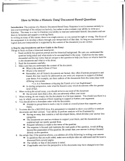


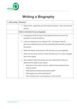

© Copyright 2026